Power Generation May, 02 Slide 1 SIEMENS POWER GENERATION – Phil Scotson.
1
NUCLEAR POWER GENERATION DESIGN PROPOSAL FOR USE IN SPACE STATIONS
UCLA MAE 133A, Spring 2011
Justin Nekota ______________________
Kaustubh Banerjee ______________________
Hang Kit “Roy” Suen ______________________
Melody Vo ______________________
Daniel Nguyen ______________________
Table of Contents
Abstract(...................................................................................................................................................(1!Introduction(...........................................................................................................................................(2!Background(.......................................................................................................................................................(2!Statement(of(Problem(....................................................................................................................................(2!Schematic(Drawings(.......................................................................................................................................(3!List(of(Assumptions(and(Constraints(........................................................................................................(4!
Design(Approach,(Methodology,(and(Calculations(....................................................................(5!Basic(Approach(and(Method(of(Solution(.................................................................................................(5!TURBINE!..............................................................................................................................................................................!6!CONDENSER!.......................................................................................................................................................................!6!PUMP!.....................................................................................................................................................................................!6!BOILER!.................................................................................................................................................................................!6!THERMAL1EFFICIENCY!..................................................................................................................................................!6!BACK1WORK1RATIO!.........................................................................................................................................................!7!IRREVERSIBILITIES1IN1PUMP1AND1TURBINE!......................................................................................................!7!
Calculations(......................................................................................................................................................(7!Economic(Considerations(..........................................................................................................................(10!
Mechanical(Design(.............................................................................................................................(11!Basic(Considerations(...................................................................................................................................(11!Engineering(Drawings(.................................................................................................................................(13!
Design(Results(and(Discussion(......................................................................................................(16!Presentation(and(Discussion(of(Major(Design(Elements(.................................................................(16!Summary(of(Major(Conclusions(...............................................................................................................(16!Recommendations(for(Further(Work(....................................................................................................(17!
References(............................................................................................................................................(18! Appendices.......................................................................................................................................( 19(
1
Abstract(
This design proposal discusses a possible alternative source of energy to provide power on a space station. The system of interest is a potassium-based Rankine cycle powered by nuclear energy. Although a typical Rankine cycle power plant can be quite large, its reuse of the working fluid makes it advantageous for ample and continuous power production over more compact power cycles like the Otto and Diesel cycles that require continuous fueling and discarding of exhausts, which is non-ideal in outer space. The use of liquid metal as the working fluid allows low pressure with high temperature heat rejection. This allows the condenser to be smaller in size (recall Q = hAΔTlm ). For that reason, the use of liquid metal in a Rankine cycle nuclear power plant will lead to a more compact size to better suit the proportions of a space station compared to using saturated water.
(
(
(
(
(
(
(
(
2
Introduction(
Background(
While solar energy is currently the primary source of power in space, nuclear power has clear advantages that make it the most viable option for future space applications: it is resistant to environmental impacts, has a lower weight-to-capacity ratio, and operates within a more compact system than solar power plants. Additionally, the power output of a nuclear plant would be independent of distance from the sun, allowing the range of the station to be extended without losing cycle efficiency. Lastly, while solar power requires the use of energy storage devices, such as fuel cells, batteries, etc., nuclear power does not. This means less equipment to launch into orbit, and less parts that could potentially fail.
The Rankine cycle in particular is of interest for space applications because of its high power-to-weight ratio at power levels of 1 MW or higher. Because of the relatively small change in temperature during heat addition and rejection, the radiator can operate at higher temperatures. This means that the radiator can be smaller, and therefore weigh less, because heat dissipation is not a large concern. Additionally, the reactor can operate at a lower temperature than in other potential cycles, such as Brayton, Stirling, etc. [1].
Statement(of(Problem(
This report addresses design considerations for a nuclear power plant in order to generate 1 MW of electricity on a space station. The proposed design utilizes a Rankine cycle with potassium as the working fluid and lithium as the primary coolant and includes specifications for the boiler, turbine, condenser, and pump. In addition, a potential condenser design has been drafted using SolidWorks and is included in the Mechanical Design section.
3
Schematic(Drawings(
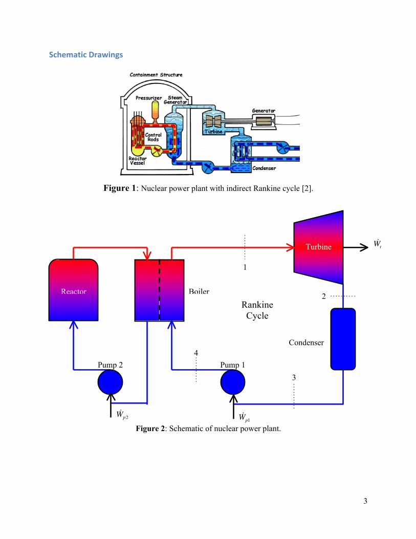
Figure 1: Nuclear power plant with indirect Rankine cycle [2].
Figure 2: Schematic of nuclear power plant.
1
2
3
4
Boiler
Turbine
Reactor
Pump 1 Pump 2
Condenser
Wt
Wp1 Wp2
Rankine Cycle
4
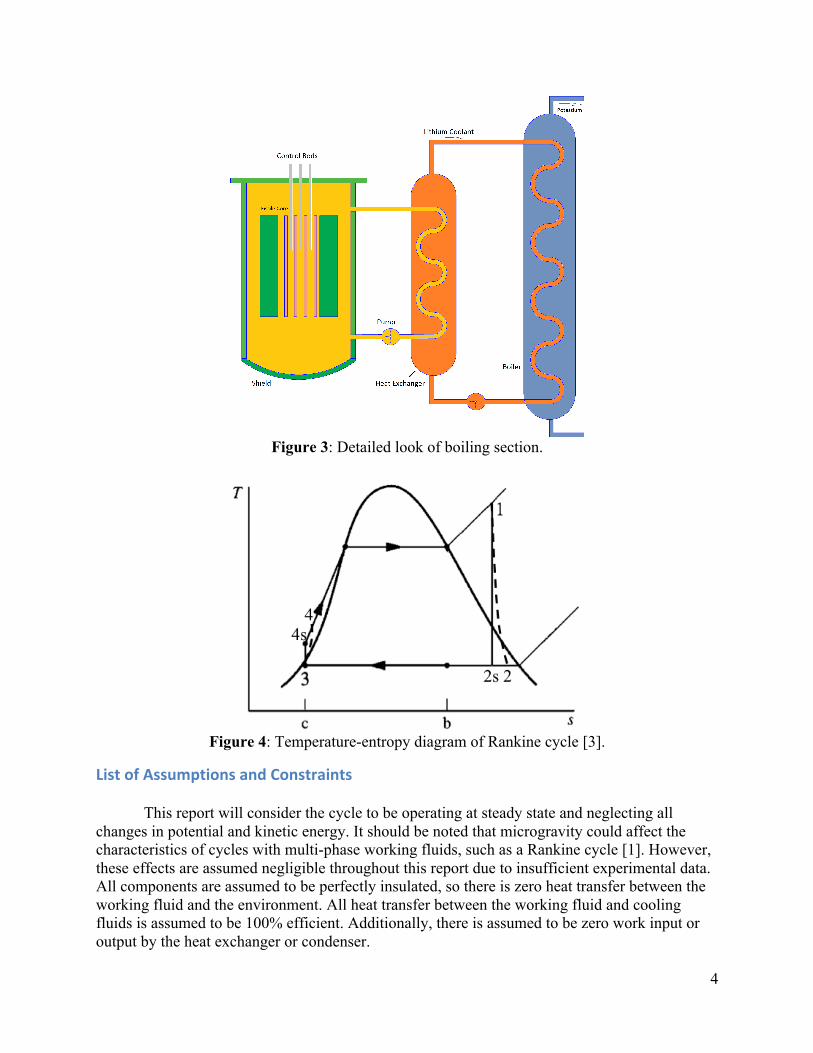
Figure 3: Detailed look of boiling section.
Figure 4: Temperature-entropy diagram of Rankine cycle [3].
List(of(Assumptions(and(Constraints(
This report will consider the cycle to be operating at steady state and neglecting all changes in potential and kinetic energy. It should be noted that microgravity could affect the characteristics of cycles with multi-phase working fluids, such as a Rankine cycle [1]. However, these effects are assumed negligible throughout this report due to insufficient experimental data. All components are assumed to be perfectly insulated, so there is zero heat transfer between the working fluid and the environment. All heat transfer between the working fluid and cooling fluids is assumed to be 100% efficient. Additionally, there is assumed to be zero work input or output by the heat exchanger or condenser.
5
Design(Approach,(Methodology,(and(Calculations(
Basic(Approach(and(Method(of(Solution(
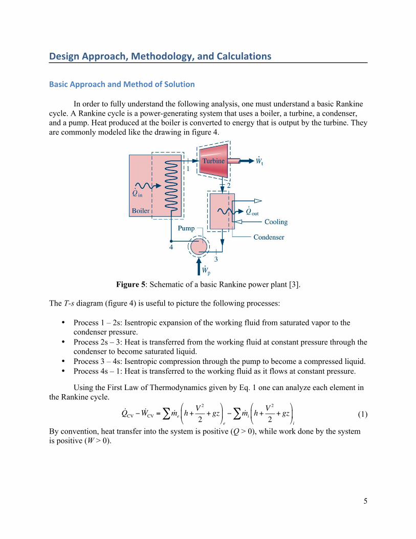
In order to fully understand the following analysis, one must understand a basic Rankine cycle. A Rankine cycle is a power-generating system that uses a boiler, a turbine, a condenser, and a pump. Heat produced at the boiler is converted to energy that is output by the turbine. They are commonly modeled like the drawing in figure 4.
Figure 5: Schematic of a basic Rankine power plant [3].
The T-s diagram (figure 4) is useful to picture the following processes:
• Process 1 – 2s: Isentropic expansion of the working fluid from saturated vapor to the condenser pressure.
• Process 2s – 3: Heat is transferred from the working fluid at constant pressure through the condenser to become saturated liquid.
• Process 3 – 4s: Isentropic compression through the pump to become a compressed liquid. • Process 4s – 1: Heat is transferred to the working fluid as it flows at constant pressure.
Using the First Law of Thermodynamics given by Eq. 1 one can analyze each element in the Rankine cycle.
(1)
By convention, heat transfer into the system is positive (Q > 0), while work done by the system is positive (W > 0).
QCV − WCV = me h+V 2
2+ gz
"
#$
%
&'e
− mi h+V 2
2+ gz
"
#$
%
&'i
∑∑
6
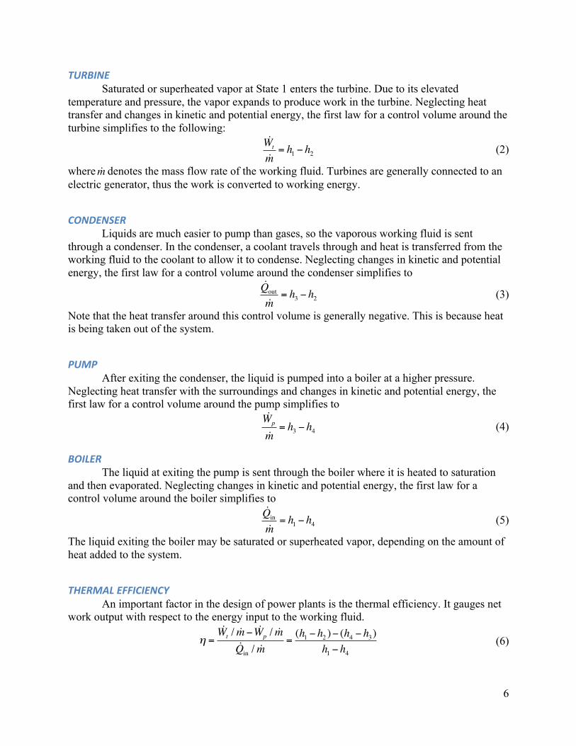
TURBINE(Saturated or superheated vapor at State 1 enters the turbine. Due to its elevated
temperature and pressure, the vapor expands to produce work in the turbine. Neglecting heat transfer and changes in kinetic and potential energy, the first law for a control volume around the turbine simplifies to the following:
where denotes the mass flow rate of the working fluid. Turbines are generally connected to an electric generator, thus the work is converted to working energy.
CONDENSER(Liquids are much easier to pump than gases, so the vaporous working fluid is sent
through a condenser. In the condenser, a coolant travels through and heat is transferred from the working fluid to the coolant to allow it to condense. Neglecting changes in kinetic and potential energy, the first law for a control volume around the condenser simplifies to
Note that the heat transfer around this control volume is generally negative. This is because heat is being taken out of the system.
PUMP(After exiting the condenser, the liquid is pumped into a boiler at a higher pressure.
Neglecting heat transfer with the surroundings and changes in kinetic and potential energy, the first law for a control volume around the pump simplifies to
BOILER(The liquid at exiting the pump is sent through the boiler where it is heated to saturation
and then evaporated. Neglecting changes in kinetic and potential energy, the first law for a control volume around the boiler simplifies to
The liquid exiting the boiler may be saturated or superheated vapor, depending on the amount of heat added to the system.
THERMAL(EFFICIENCY(An important factor in the design of power plants is the thermal efficiency. It gauges net
work output with respect to the energy input to the working fluid.
m
(2)
(3)
(4)
(5)
(6)
Wt
m= h1 − h2
Qout
m= h3 − h2
Wp
m= h3 − h4
Qin
m= h1 − h4
η =Wt / m− Wp / mQin / m
=(h1 − h2 )− (h4 − h3)
h1 − h4
7
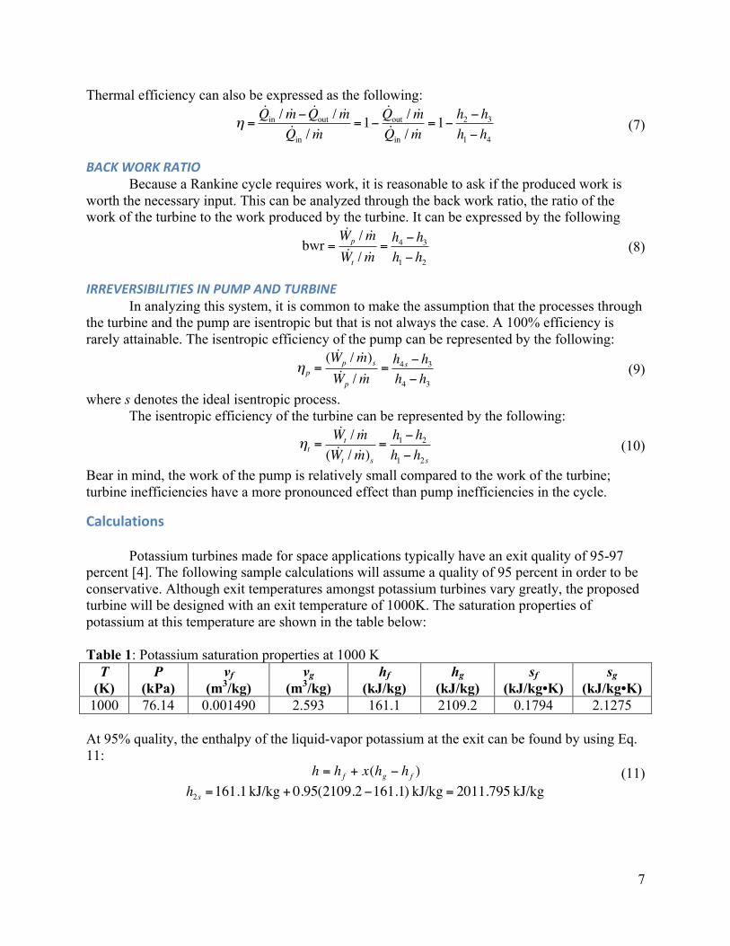
Thermal efficiency can also be expressed as the following:
BACK(WORK(RATIO(Because a Rankine cycle requires work, it is reasonable to ask if the produced work is
worth the necessary input. This can be analyzed through the back work ratio, the ratio of the work of the turbine to the work produced by the turbine. It can be expressed by the following
IRREVERSIBILITIES(IN(PUMP(AND(TURBINE(In analyzing this system, it is common to make the assumption that the processes through
the turbine and the pump are isentropic but that is not always the case. A 100% efficiency is rarely attainable. The isentropic efficiency of the pump can be represented by the following:
where s denotes the ideal isentropic process. The isentropic efficiency of the turbine can be represented by the following:
Bear in mind, the work of the pump is relatively small compared to the work of the turbine; turbine inefficiencies have a more pronounced effect than pump inefficiencies in the cycle.
Calculations(
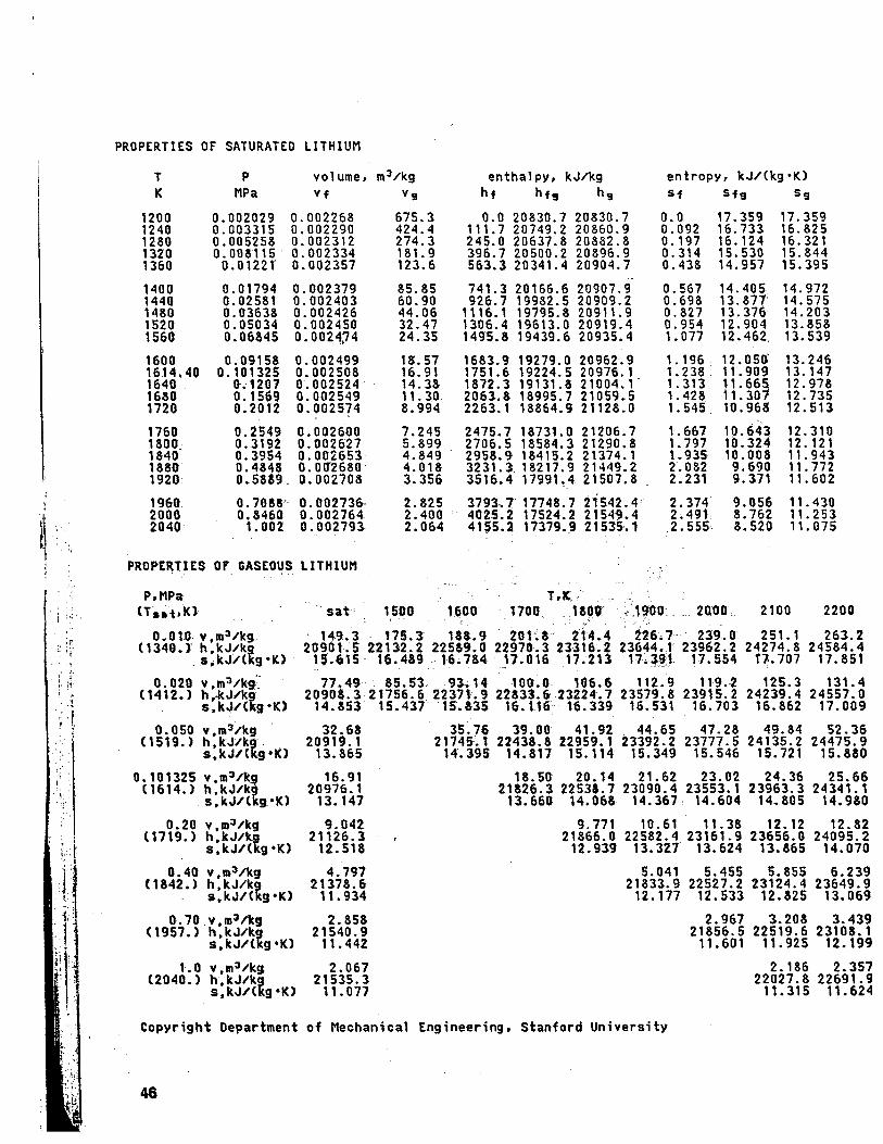
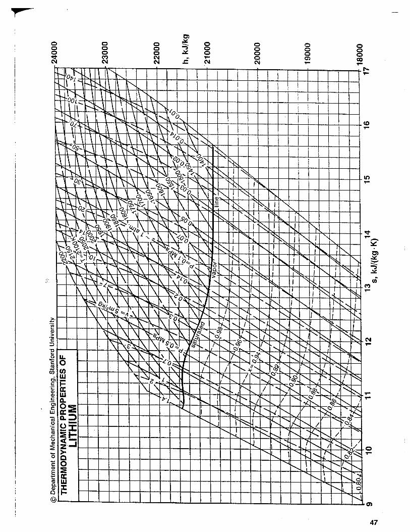
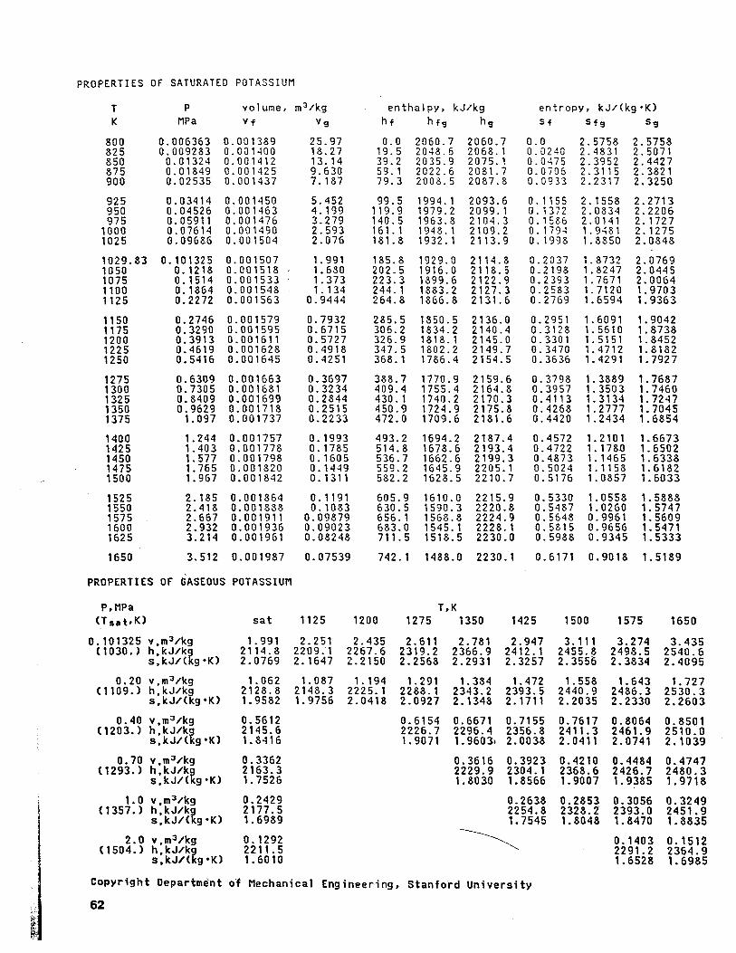
Potassium turbines made for space applications typically have an exit quality of 95-97 percent [4]. The following sample calculations will assume a quality of 95 percent in order to be conservative. Although exit temperatures amongst potassium turbines vary greatly, the proposed turbine will be designed with an exit temperature of 1000K. The saturation properties of potassium at this temperature are shown in the table below: Table 1: Potassium saturation properties at 1000 K
T (K)
P (kPa)
vf (m3/kg)
vg (m3/kg)
hf (kJ/kg)
hg (kJ/kg)
sf (kJ/kg•K)
sg (kJ/kg•K)
1000 76.14 0.001490 2.593 161.1 2109.2 0.1794 2.1275 At 95% quality, the enthalpy of the liquid-vapor potassium at the exit can be found by using Eq. 11: (11)
€
h = hf + x(hg − h f )h2s =161.1 kJ/kg + 0.95(2109.2−161.1) kJ/kg = 2011.795 kJ/kg
(7)
(8)
(9)
(10)
η =Qin / m− Qout / mQin / m
=1−Qout / mQin / m
=1− h2 − h3h1 − h4
bwr =Wp / mWt / m
=h4 − h3h1 − h2
ηp =( Wp / m)sWp / m
=h4s − h3h4 − h3
ηt =Wt / m
( Wt / m)s=h1 − h2h1 − h2s
8
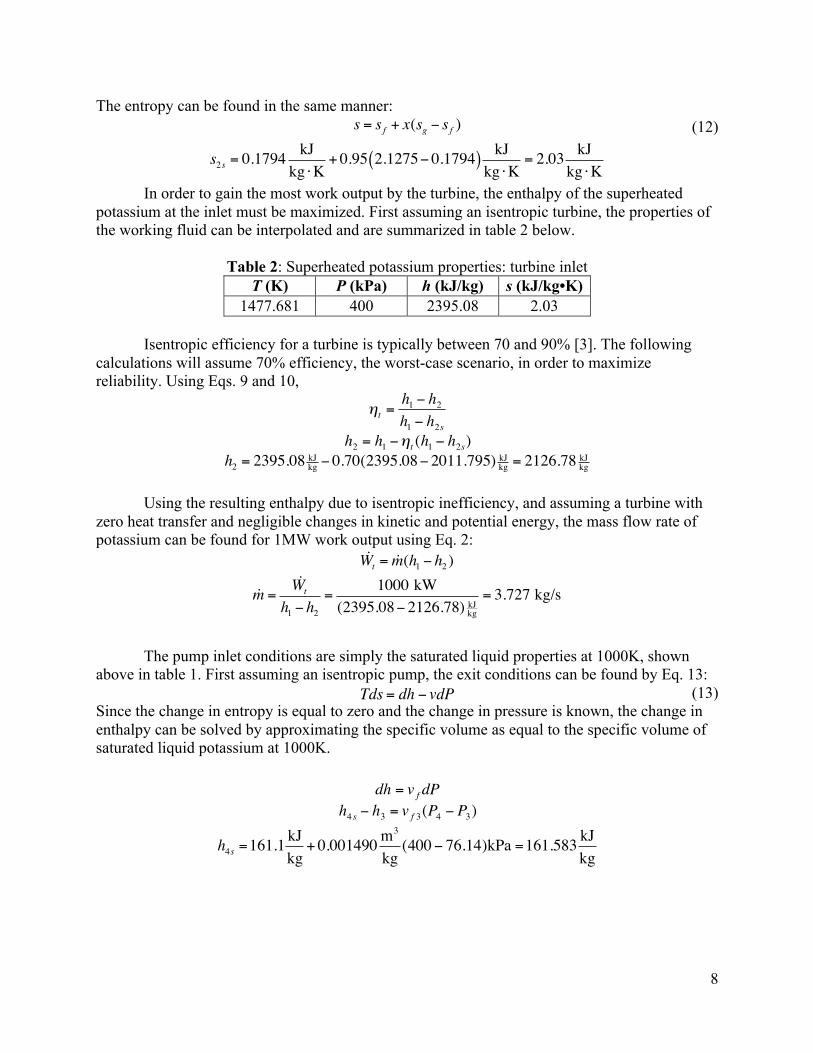
The entropy can be found in the same manner: (12)
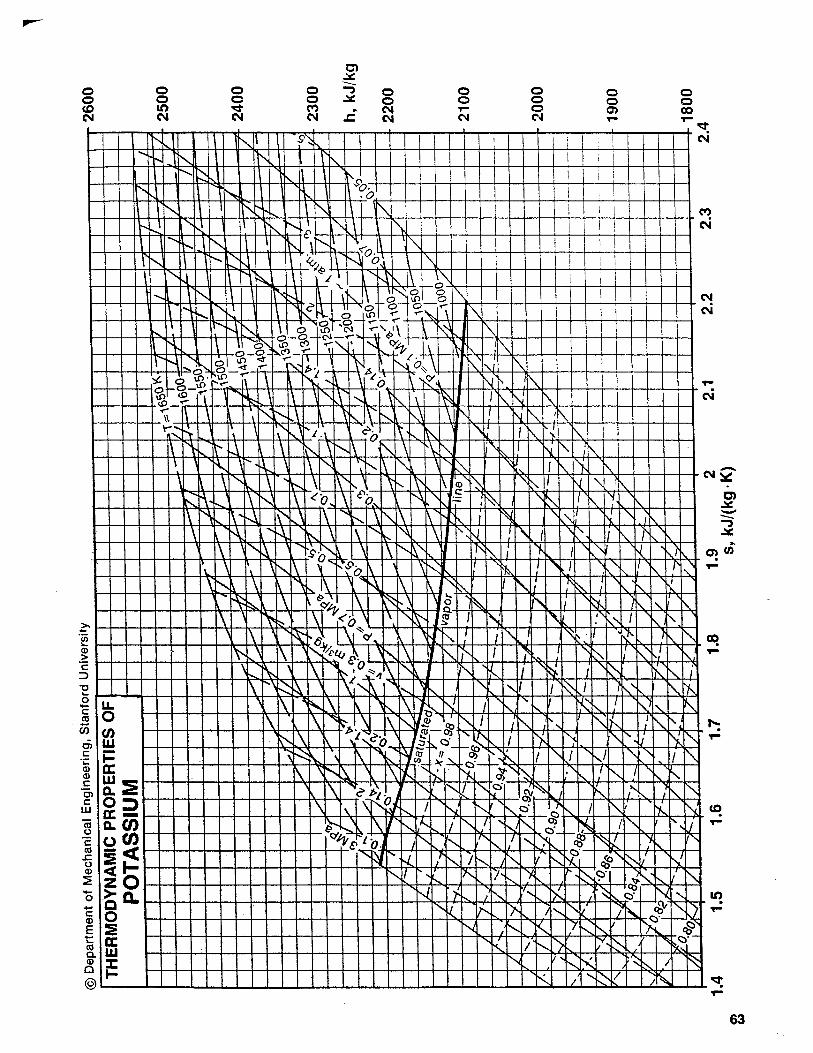
In order to gain the most work output by the turbine, the enthalpy of the superheated potassium at the inlet must be maximized. First assuming an isentropic turbine, the properties of the working fluid can be interpolated and are summarized in table 2 below.
Table 2: Superheated potassium properties: turbine inlet T (K) P (kPa) h (kJ/kg) s (kJ/kg•K)
1477.681 400 2395.08 2.03
Isentropic efficiency for a turbine is typically between 70 and 90% [3]. The following calculations will assume 70% efficiency, the worst-case scenario, in order to maximize reliability. Using Eqs. 9 and 10,
Using the resulting enthalpy due to isentropic inefficiency, and assuming a turbine with zero heat transfer and negligible changes in kinetic and potential energy, the mass flow rate of potassium can be found for 1MW work output using Eq. 2:
The pump inlet conditions are simply the saturated liquid properties at 1000K, shown above in table 1. First assuming an isentropic pump, the exit conditions can be found by Eq. 13: (13) Since the change in entropy is equal to zero and the change in pressure is known, the change in enthalpy can be solved by approximating the specific volume as equal to the specific volume of saturated liquid potassium at 1000K.
s = s f + x(sg − s f )
s2s = 0.1794kJkg ⋅K
+ 0.95 2.1275− 0.1794( ) kJkg ⋅K
= 2.03 kJkg ⋅K
€
ηt =h1 − h2h1 − h2s
€
h2 = h1 −ηt (h1 − h2s)h2 = 2395.08 kJkg − 0.70(2395.08− 2011.795) kJkg = 2126.78 kJkg
Wt = m(h1 − h2 )
m =Wt
h1 − h2
=1000 kW
(2395.08− 2126.78) kJkg
= 3.727 kg/s
€
Tds = dh − vdP
€
dh = v f dP
€
h4 s − h3 = v f 3(P4 − P3)
h4s =161.1kJkg
+ 0.001490 m3
kg(400− 76.14)kPa =161.583 kJ
kg
9
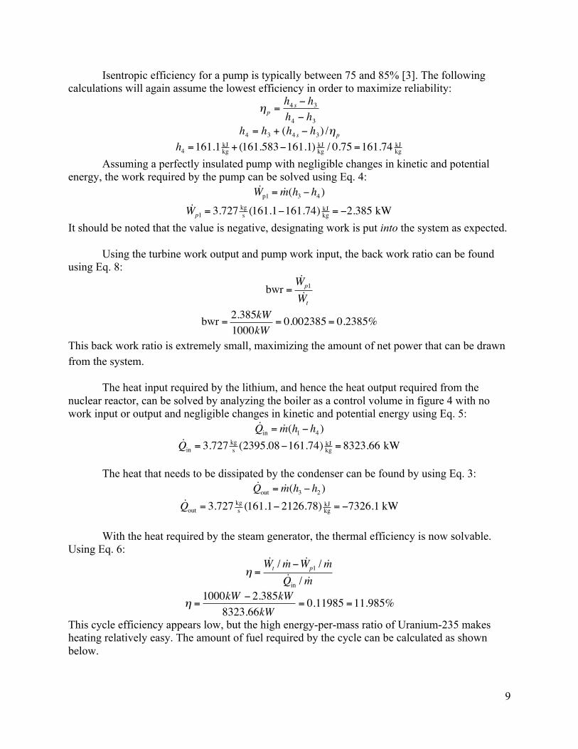
Isentropic efficiency for a pump is typically between 75 and 85% [3]. The following calculations will again assume the lowest efficiency in order to maximize reliability:
Assuming a perfectly insulated pump with negligible changes in kinetic and potential
energy, the work required by the pump can be solved using Eq. 4:
It should be noted that the value is negative, designating work is put into the system as expected.
Using the turbine work output and pump work input, the back work ratio can be found using Eq. 8:
This back work ratio is extremely small, maximizing the amount of net power that can be drawn from the system.
The heat input required by the lithium, and hence the heat output required from the nuclear reactor, can be solved by analyzing the boiler as a control volume in figure 4 with no work input or output and negligible changes in kinetic and potential energy using Eq. 5:
The heat that needs to be dissipated by the condenser can be found by using Eq. 3:
With the heat required by the steam generator, the thermal efficiency is now solvable. Using Eq. 6:
This cycle efficiency appears low, but the high energy-per-mass ratio of Uranium-235 makes heating relatively easy. The amount of fuel required by the cycle can be calculated as shown below.
€
ηp =h4 s − h3h4 − h3
€
h4 = h3 + (h4 s − h3) /ηp
h4 =161.1 kJkg + (161.583−161.1) kJkg / 0.75=161.74 kJkg
Wp1 = m(h3 − h4 )Wp1 = 3.727 kg
s (161.1−161.74) kJkg = −2.385 kW
bwr =Wp1
Wt
bwr = 2.385kW1000kW
= 0.002385= 0.2385%
Qin = m(h1 − h4 )Qin = 3.727 kg
s (2395.08−161.74) kJkg = 8323.66 kW
Qout = m(h3 − h2 )Qout = 3.727 kg
s (161.1− 2126.78) kJkg = −7326.1 kW
η =Wt / m− Wp1 / mQin / m
€
η =1000kW − 2.385kW
8323.66kW= 0.11985 =11.985%
10
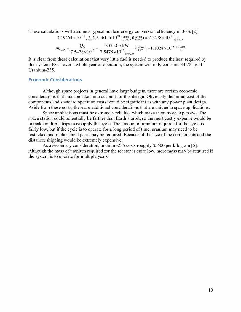
These calculations will assume a typical nuclear energy conversion efficiency of 30% [2]:
It is clear from these calculations that very little fuel is needed to produce the heat required by this system. Even over a whole year of operation, the system will only consume 34.78 kg of Uranium-235.
Economic(Considerations(
Although space projects in general have large budgets, there are certain economic considerations that must be taken into account for this design. Obviously the initial cost of the components and standard operation costs would be significant as with any power plant design. Aside from these costs, there are additional considerations that are unique to space applications.
Space applications must be extremely reliable, which make them more expensive. The space station could potentially be farther than Earth’s orbit, so the most costly expense would be to make multiple trips to resupply the cycle. The amount of uranium required for the cycle is fairly low, but if the cycle is to operate for a long period of time, uranium may need to be restocked and replacement parts may be required. Because of the size of the components and the distance, shipping would be extremely expensive.
As a secondary consideration, uranium-235 costs roughly $5600 per kilogram [5]. Although the mass of uranium required for the reactor is quite low, more mass may be required if the system is to operate for multiple years.
(2.9464×10⁻¹¹ Jevent )(2.5617×1024 atoms
kg U235)(1event1atom ) = 7.5478×10¹² J
kgU235
mU 235 =Qin
7.5478×1012 =8323.66 kW
7.5478×10¹² JkgU 235
(1000J1 kW ) =1.1028×10⁻⁶ kg U235
s
11
Mechanical(Design
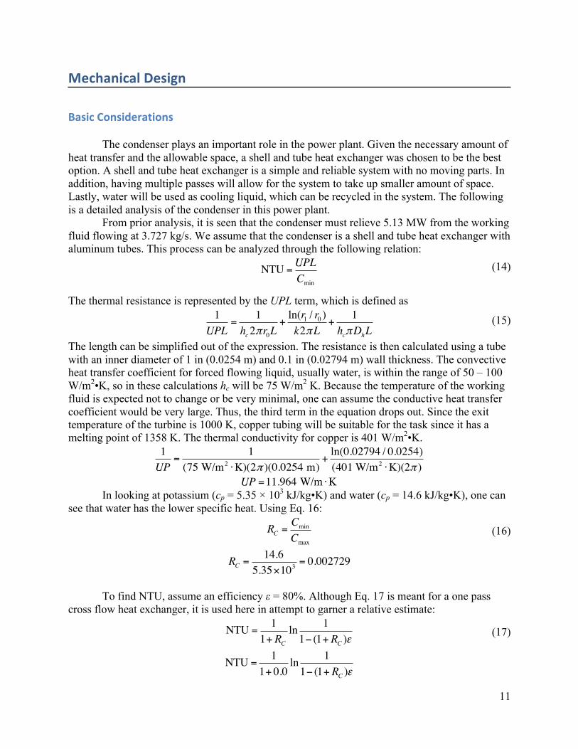
Basic(Considerations( The condenser plays an important role in the power plant. Given the necessary amount of heat transfer and the allowable space, a shell and tube heat exchanger was chosen to be the best option. A shell and tube heat exchanger is a simple and reliable system with no moving parts. In addition, having multiple passes will allow for the system to take up smaller amount of space. Lastly, water will be used as cooling liquid, which can be recycled in the system. The following is a detailed analysis of the condenser in this power plant. From prior analysis, it is seen that the condenser must relieve 5.13 MW from the working fluid flowing at 3.727 kg/s. We assume that the condenser is a shell and tube heat exchanger with aluminum tubes. This process can be analyzed through the following relation: NTU =
UPLCmin
(14)
The thermal resistance is represented by the UPL term, which is defined as 1
UPL=
1hc2πr0L
+ln(r1 / r0 )k2πL
+1
hcπDhL (15)
The length can be simplified out of the expression. The resistance is then calculated using a tube with an inner diameter of 1 in (0.0254 m) and 0.1 in (0.02794 m) wall thickness. The convective heat transfer coefficient for forced flowing liquid, usually water, is within the range of 50 – 100 W/m2•K, so in these calculations hc will be 75 W/m2 K. Because the temperature of the working fluid is expected not to change or be very minimal, one can assume the conductive heat transfer coefficient would be very large. Thus, the third term in the equation drops out. Since the exit temperature of the turbine is 1000 K, copper tubing will be suitable for the task since it has a melting point of 1358 K. The thermal conductivity for copper is 401 W/m2•K.
1UP
=1
(75 W/m2 ⋅K)(2π )(0.0254 m)+
ln(0.02794 / 0.0254)(401 W/m2 ⋅K)(2π )
UP =11.964 W/m ⋅K In looking at potassium (cp = 5.35 × 10³ kJ/kg•K) and water (cp = 14.6 kJ/kg•K), one can see that water has the lower specific heat. Using Eq. 16:
RC =CminCmax
(16)
RC =14.6
5.35×103= 0.002729
To find NTU, assume an efficiency ε = 80%. Although Eq. 17 is meant for a one pass cross flow heat exchanger, it is used here in attempt to garner a relative estimate:
NTU =1
1+ RCln 11− (1+ RC )ε
(17)
NTU =1
1+ 0.0ln 11− (1+ RC )ε
12
Returning to Eq. 14,
1.616 = (11.96 W/m ⋅K)L14.6 kJ/kg ⋅K
! L = 1.97 m
This is not as much of a literal design result as it is a key to understanding the size necessary for the condenser. With the assumptions made, one can estimate the amount of cooling fluid necessary using Eq. 18: Q = mhΔT (18) where Q=5.13 MW and h = 75 W/m2•K. To get a reasonable temperature change (around 100 K in the water), the mass flow rate would be over 600 kg/s. This is a rather large mass flow rate for cooling water. In order to create the effect of having that much water, there will be a need for multiple passes at longer lengths to properly condense the working fluid.
Efficiency in repair and maintenance is of utmost importance in our setting of a space station not only for operational reasons, but more significantly for safety. The power plant will built in a modular fashion, so that every component including the reactor may be replaced without requiring much disassembly. Such a design would require more space but would enable for quick repair and replacement. As discussed earlier, our Rankine cycle design functions at high temperatures. This factor reduces the materials we can use for the power plant. We considered using stainless steel for the various components, however the weight of our system would be very large and for safety reasons we would need to run the power cycle at lower temperatures, reducing the output and efficiency. Thus, to run our system at higher temperatures we will use Ta-111 alloy, which has a higher density and can be used at higher operational temperatures [4]. From strength limitations the maximum material temperature limit for the alloy is 1500 K. Since tantalum is economically unreasonable to use for structural supports and the like, secondary systems would use stainless steel with a temperature limit of 1000 K. To improve the heat exchanger efficiency in the condenser, we utilized copper for its high thermal conductivity. Copper is a more expensive alternative, but by using copper we would require a smaller condenser and consequently less material. Since payload weight in space is a major consideration for our application, the cost of copper will be offset by the overall design being more cost effective. With limited space and confined environment of a space station, nuclear waste and spent fuel is an important consideration in our design. The fast breeder type nuclear reactor not only boasts high fuel efficiencies and high burn up to optimize energy output, but also minimal wastes. This waste would need to be stored and periodically transported back to Earth for disposal. However, the waste produced would be significantly lower in comparison to normal reactor designs. Radiation shielding for the nuclear reactor is also an important factor. With long term habitation of the space station radiation exposure needs to be minimal. Use of materials such as lead and concrete will be very expensive for use in a space station. Thus we will use lithium hydride, a lighter alternative. This is a proven material and has been used as shielding for reactors in space due to its high hydrogen content for scattering radiation, high melting temperature, and low density [6]. The pump was another part taken into consideration for design. It was decided to model the pump as a centrifugal pump. It was chosen for its reliability. There is no metal to metal contact under high pressure which reduces the wear of the pump. The only major forces are at
13
the mechanical seal and bearing. In addition to being durable, the pump’s parts can be easily replaced with time. A centrifugal pump can be compact and still operate at high pressures. They also have good controllability at any flow rate, and can consistently control a constant flow rate.
Engineering(Drawings(
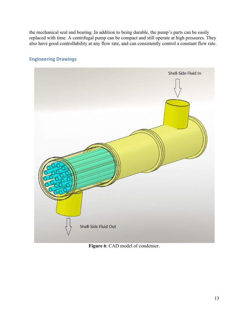
Figure 6: CAD model of condenser.
14
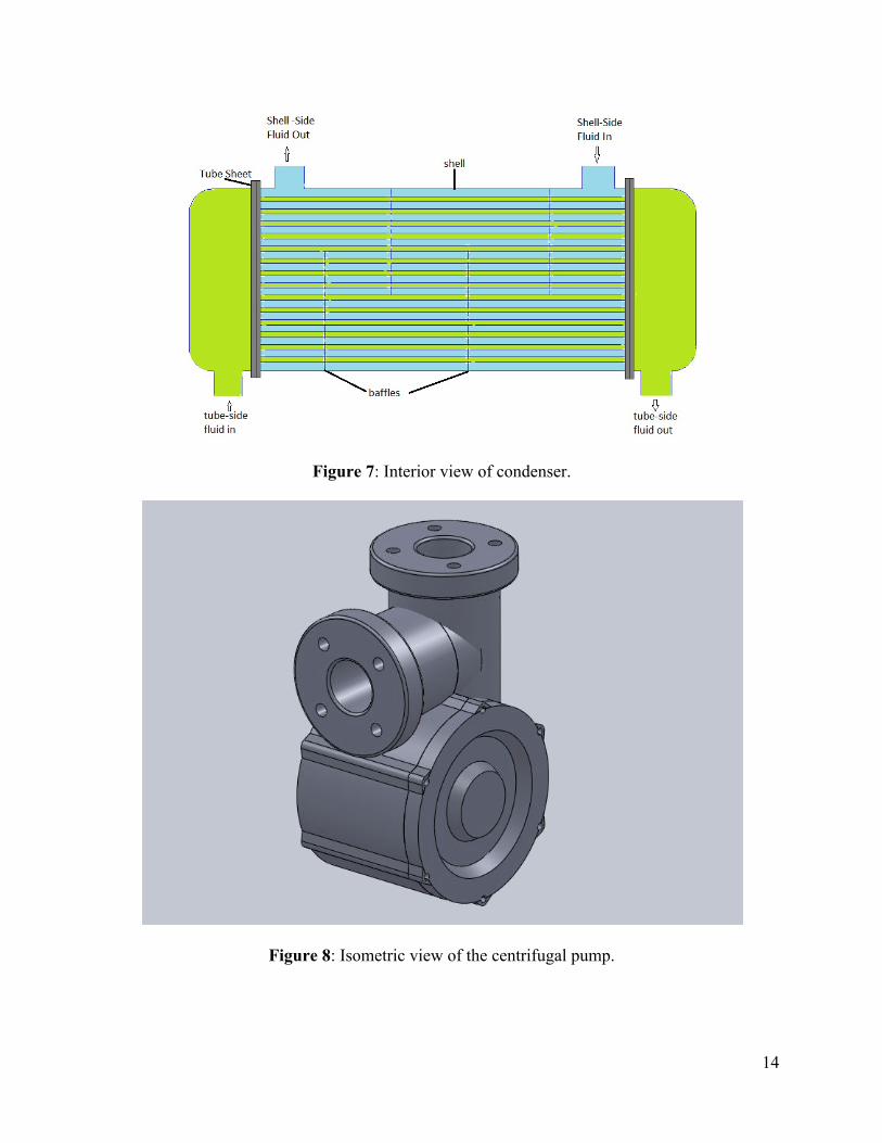
Figure 7: Interior view of condenser.
Figure 8: Isometric view of the centrifugal pump.
15
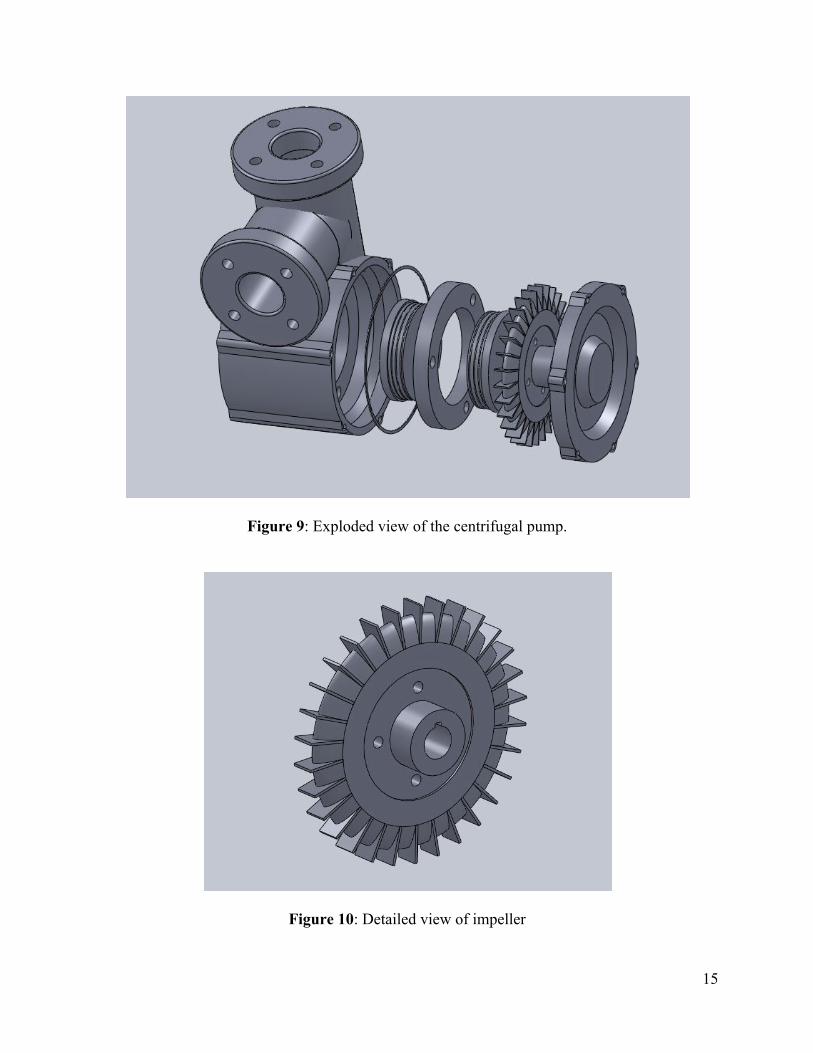
Figure 9: Exploded view of the centrifugal pump.
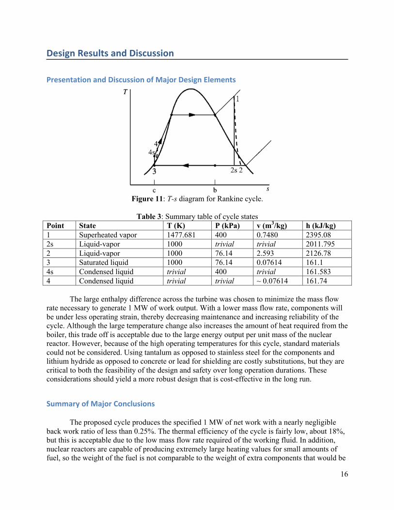
Figure 10: Detailed view of impeller
16
Design(Results(and(Discussion(
Presentation(and(Discussion(of(Major(Design(Elements(
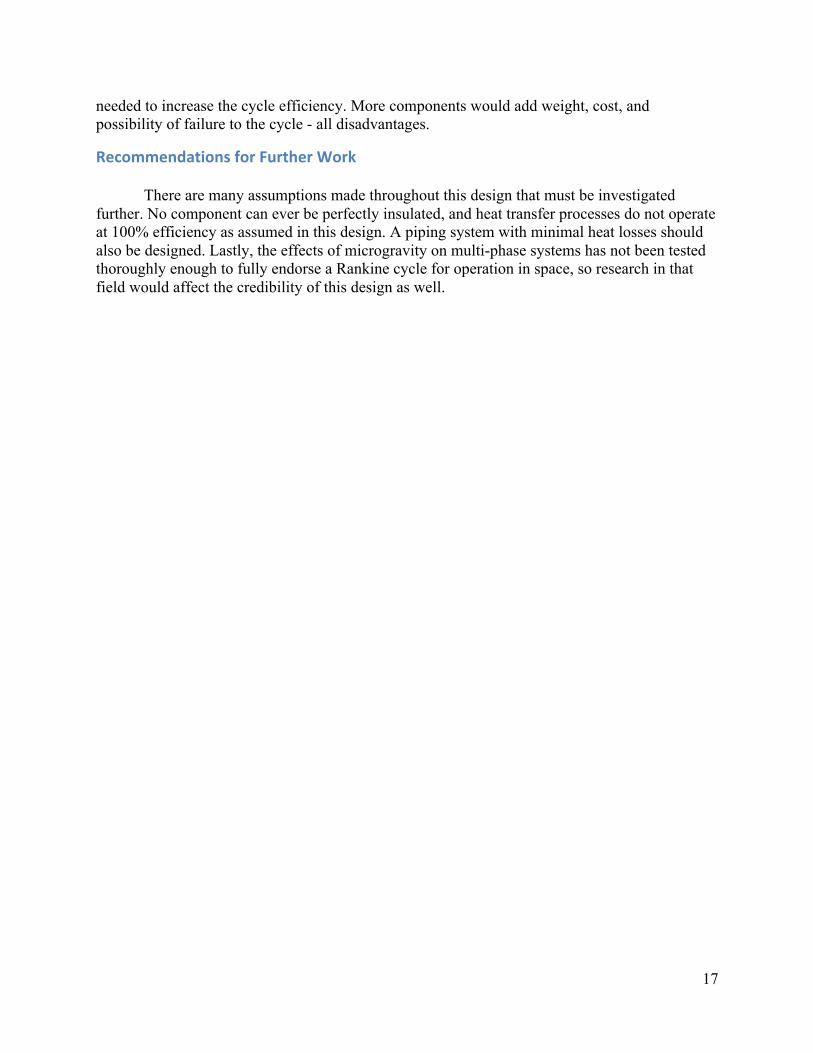
Figure 11: T-s diagram for Rankine cycle.
Table 3: Summary table of cycle states
Point State T (K) P (kPa) v (m3/kg) h (kJ/kg) 1 Superheated vapor 1477.681 400 0.7480 2395.08 2s Liquid-vapor 1000 trivial trivial 2011.795 2 Liquid-vapor 1000 76.14 2.593 2126.78 3 Saturated liquid 1000 76.14 0.07614 161.1 4s Condensed liquid trivial 400 trivial 161.583 4 Condensed liquid trivial trivial ~ 0.07614 161.74
The large enthalpy difference across the turbine was chosen to minimize the mass flow rate necessary to generate 1 MW of work output. With a lower mass flow rate, components will be under less operating strain, thereby decreasing maintenance and increasing reliability of the cycle. Although the large temperature change also increases the amount of heat required from the boiler, this trade off is acceptable due to the large energy output per unit mass of the nuclear reactor. However, because of the high operating temperatures for this cycle, standard materials could not be considered. Using tantalum as opposed to stainless steel for the components and lithium hydride as opposed to concrete or lead for shielding are costly substitutions, but they are critical to both the feasibility of the design and safety over long operation durations. These considerations should yield a more robust design that is cost-effective in the long run.
Summary(of(Major(Conclusions( The proposed cycle produces the specified 1 MW of net work with a nearly negligible back work ratio of less than 0.25%. The thermal efficiency of the cycle is fairly low, about 18%, but this is acceptable due to the low mass flow rate required of the working fluid. In addition, nuclear reactors are capable of producing extremely large heating values for small amounts of fuel, so the weight of the fuel is not comparable to the weight of extra components that would be
17
needed to increase the cycle efficiency. More components would add weight, cost, and possibility of failure to the cycle - all disadvantages.
Recommendations(for(Further(Work( There are many assumptions made throughout this design that must be investigated
further. No component can ever be perfectly insulated, and heat transfer processes do not operate at 100% efficiency as assumed in this design. A piping system with minimal heat losses should also be designed. Lastly, the effects of microgravity on multi-phase systems has not been tested thoroughly enough to fully endorse a Rankine cycle for operation in space, so research in that field would affect the credibility of this design as well.
18
References(
1. Lahey, Jr., R.T., and Dhir, V.,Research in Support of the Use of Rankine Cycle Energy Conversion Systems for Power and Propulsion. Tech. Cleveland, OH: Glenn Reseach Center, 2004. Print.
2. Pilon, L., "Clean Energy I: Conventional Power Generation." Mechanical & Aerospace Engineering Department, University of California, Los Angeles. Lecture.
3. Moran, M.J. and Shapiro, H.N., Fundamentals of Engineering Thermodynamics, 6th ed., Wiley, New York, 2008.
4. Yoder, Jr., G.L., Carbajo, J.J., Murphy, R.W., Qualls, A.L., Sulfredge,C.D., Moriarty, M.P., Widman, F.J., Metcalf, K.J., and Nikitkin, M.,Technology Development Program for an Advanced Potassium Rankine Power Conversion System Compatible with Several Space Reactor Designs. Tech. Oak Ridge, TN: Oak Ridge National Laboratory, 2005. Print.
5. "Plutonium as an Energy Source." Institute for Energy and Environmental Research Homepage. Web. 03 June 2011. <http://www.ieer.org/ensec/no-1/puuse.html>.
6. Welch, Frank H. "ScienceDirect - Nuclear Engineering and Design : Lithium Hydride: A Space Age Shielding Material." ScienceDirect - Home. 26 Feb. 2003. Web. 03 June 2011. <http://www.sciencedirect.com/science/article/pii/002954937490082X>.