
Nuclear Associates 07-661-7662 - Flukeassets.fluke.com/manuals/661_7662omeng0000.pdf · Nuclear...
12
Nuclear Associates 07-661-7662 Collimator/Beam Alignment Test Tool Operators Manual March 2005 Manual No. 07-661-7662-1 Rev. 2 ©2004, 2005 Fluke Corporation, All rights reserved. Printed in U.S.A. All product names are trademarks of their respective companies
Transcript of Nuclear Associates 07-661-7662 - Flukeassets.fluke.com/manuals/661_7662omeng0000.pdf · Nuclear...
Nuclear Associates 07-661-7662
Collimator/Beam Alignment Test Tool
Operators Manual March 2005 Manual No. 07-661-7662-1 Rev. 2 ©2004, 2005 Fluke Corporation, All rights reserved. Printed in U.S.A. All product names are trademarks of their respective companies

Fluke Biomedical Radiation Management Services 6045 Cochran Road Cleveland, Ohio 44139 440.498.2564 120 Andrews Road Hicksville, New York 11801 516.870.0100 www.flukebiomedical.com/rms
i
Table of Contents
Section 1: Introduction................................................................................................ 1-1 1.1 General Description ..................................................................................... 1-1 1.2 Procedure - Radiographic ............................................................................ 1-1 1.3 Interpretation of Results............................................................................... 1-2 1.3.1 Collimation ............................................................................................ 1-2 1.3.2 Alignment of X-Ray Field and Image Receptor ..................................... 1-3 1.3.3 Beam Alignment.................................................................................... 1-4 1.4 Procedure - Fluoroscopic............................................................................. 1-4 1.5 Image Intensifier .......................................................................................... 1-4 1.6 Checking Spot Film Collimation ................................................................... 1-6

(Blank page)
IntroductionGeneral Description 1
1-1
Section 1 Introduction
1.1 General Description
A common problem of x-ray units is the misalignment of the collimator light field and the x-ray field. The Collimator Test Tool is designed to evaluate this light x-ray alignment according to National Center for Devices and Radiological Health (NCDRH) specifications. The Beam Alignment Test Tool, when used with the Collimator Test Tool, provides a simple test for beam alignment.
The Beam Alignment Test Tool is a plastic cylinder, 6" tall with a 1/16" diameter steel ball at each end. When the tool sits upright on a level surface, the upper ball is directly above the one in the base. The Collimator Test Tool is a flat plate with a rectangular outline and markings etched on its surface.
1.2 Procedure – Radiographic
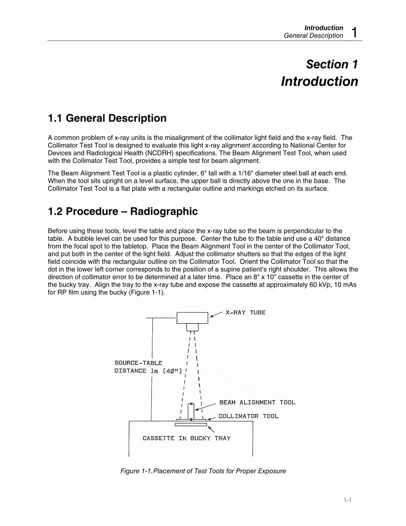
Before using these tools, level the table and place the x-ray tube so the beam is perpendicular to the table. A bubble level can be used for this purpose. Center the tube to the table and use a 40" distance from the focal spot to the tabletop. Place the Beam Alignment Tool in the center of the Collimator Tool, and put both in the center of the light field. Adjust the collimator shutters so that the edges of the light field coincide with the rectangular outline on the Collimator Tool. Orient the Collimator Tool so that the dot in the lower left corner corresponds to the position of a supine patient’s right shoulder. This allows the direction of collimator error to be determined at a later time. Place an 8" x 10" cassette in the center of the bucky tray. Align the tray to the x-ray tube and expose the cassette at approximately 60 kVp, 10 mAs for RP film using the bucky (Figure 1-1).
Figure 1-1. Placement of Test Tools for Proper Exposure
Nuclear Associates 07-661-7662 Operators Manual
1-2
1.3 Interpretation of Results
1.3.1 Collimation
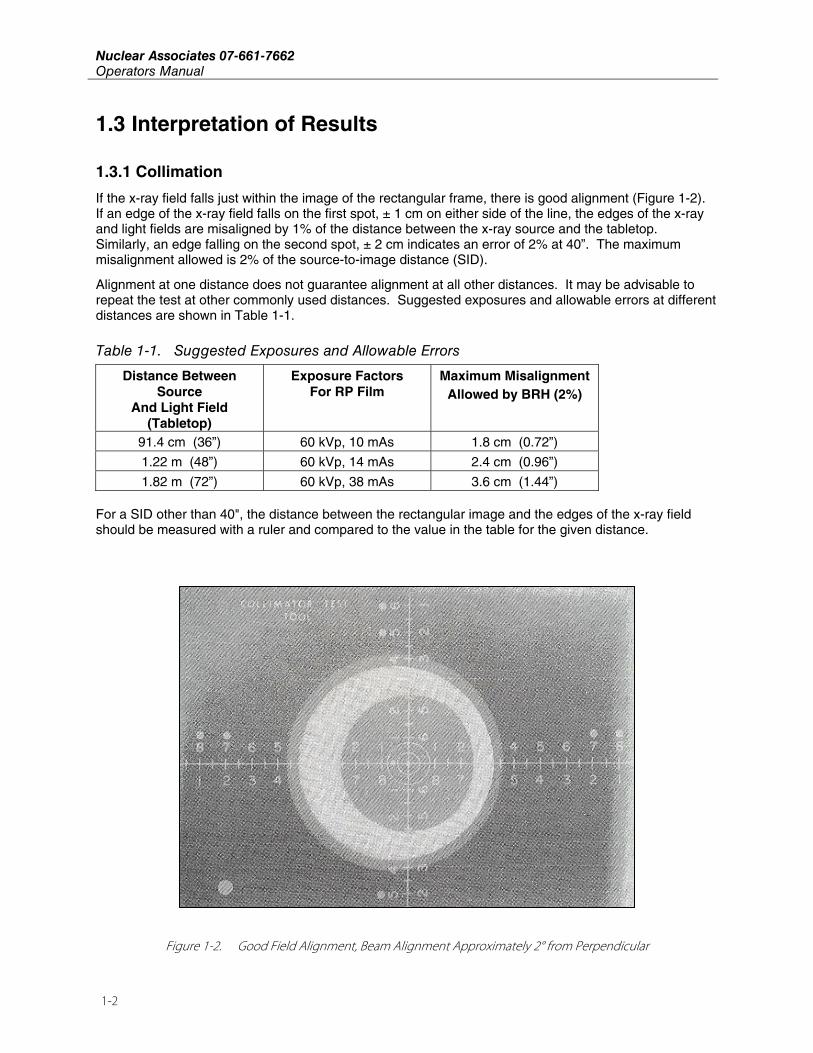
If the x-ray field falls just within the image of the rectangular frame, there is good alignment (Figure 1-2). If an edge of the x-ray field falls on the first spot, ± 1 cm on either side of the line, the edges of the x-ray and light fields are misaligned by 1% of the distance between the x-ray source and the tabletop. Similarly, an edge falling on the second spot, ± 2 cm indicates an error of 2% at 40”. The maximum misalignment allowed is 2% of the source-to-image distance (SID).
Alignment at one distance does not guarantee alignment at all other distances. It may be advisable to repeat the test at other commonly used distances. Suggested exposures and allowable errors at different distances are shown in Table 1-1.
Table 1-1. Suggested Exposures and Allowable Errors
Distance Between Source
And Light Field (Tabletop)
Exposure Factors For RP Film
Maximum Misalignment Allowed by BRH (2%)
91.4 cm (36”) 60 kVp, 10 mAs 1.8 cm (0.72”)
1.22 m (48”) 60 kVp, 14 mAs 2.4 cm (0.96”)
1.82 m (72”) 60 kVp, 38 mAs 3.6 cm (1.44”) For a SID other than 40", the distance between the rectangular image and the edges of the x-ray field should be measured with a ruler and compared to the value in the table for the given distance.
Figure 1-2. Good Field Alignment, Beam Alignment Approximately 2° from Perpendicular
IntroductionInterpretation of Results 1
1-3
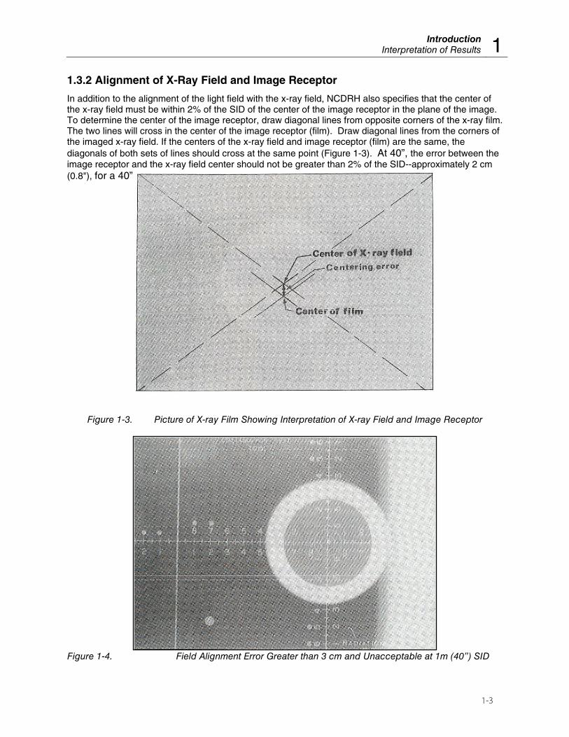
1.3.2 Alignment of X-Ray Field and Image Receptor
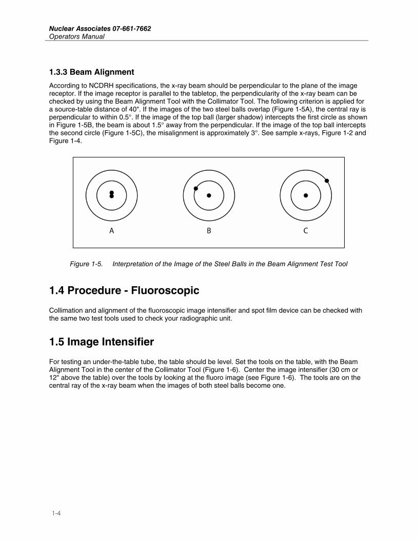
In addition to the alignment of the light field with the x-ray field, NCDRH also specifies that the center of the x-ray field must be within 2% of the SID of the center of the image receptor in the plane of the image. To determine the center of the image receptor, draw diagonal lines from opposite corners of the x-ray film. The two lines will cross in the center of the image receptor (film). Draw diagonal lines from the corners of the imaged x-ray field. If the centers of the x-ray field and image receptor (film) are the same, the diagonals of both sets of lines should cross at the same point (Figure 1-3). At 40”, the error between the image receptor and the x-ray field center should not be greater than 2% of the SID--approximately 2 cm (0.8"), for a 40” source-table distance (Figure 1-4).
Figure 1-3. Picture of X-ray Film Showing Interpretation of X-ray Field and Image Receptor
Figure 1-4. Field Alignment Error Greater than 3 cm and Unacceptable at 1m (40”) SID
Nuclear Associates 07-661-7662 Operators Manual
1-4
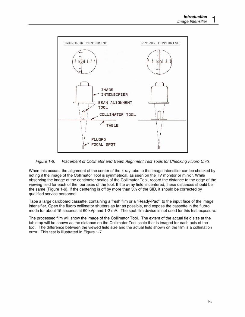
1.3.3 Beam Alignment
According to NCDRH specifications, the x-ray beam should be perpendicular to the plane of the image receptor. If the image receptor is parallel to the tabletop, the perpendicularity of the x-ray beam can be checked by using the Beam Alignment Tool with the Collimator Tool. The following criterion is applied for a source-table distance of 40". If the images of the two steel balls overlap (Figure 1-5A), the central ray is perpendicular to within 0.5°. If the image of the top ball (larger shadow) intercepts the first circle as shown in Figure 1-5B, the beam is about 1.5° away from the perpendicular. If the image of the top ball intercepts the second circle (Figure 1-5C), the misalignment is approximately 3°. See sample x-rays, Figure 1-2 and Figure 1-4.
Figure 1-5. Interpretation of the Image of the Steel Balls in the Beam Alignment Test Tool
1.4 Procedure - Fluoroscopic
Collimation and alignment of the fluoroscopic image intensifier and spot film device can be checked with the same two test tools used to check your radiographic unit.
1.5 Image Intensifier
For testing an under-the-table tube, the table should be level. Set the tools on the table, with the Beam Alignment Tool in the center of the Collimator Tool (Figure 1-6). Center the image intensifier (30 cm or 12" above the table) over the tools by looking at the fluoro image (see Figure 1-6). The tools are on the central ray of the x-ray beam when the images of both steel balls become one.
IntroductionImage Intensifier 1
1-5
Figure 1-6. Placement of Collimator and Beam Alignment Test Tools for Checking Fluoro Units
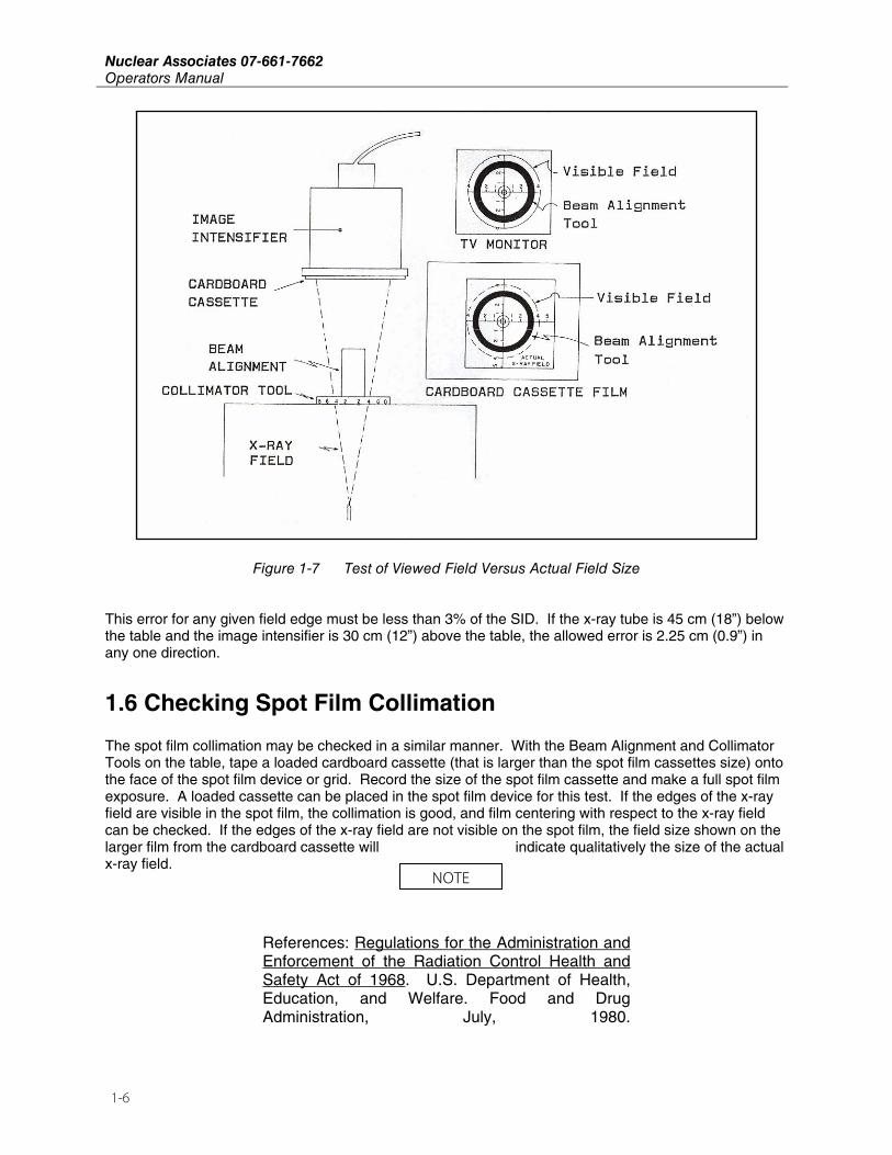
When this occurs, the alignment of the center of the x-ray tube to the image intensifier can be checked by noting if the image of the Collimator Tool is symmetrical, as seen on the TV monitor or mirror. While observing the image of the centimeter scales of the Collimator Tool, record the distance to the edge of the viewing field for each of the four axes of the tool. If the x-ray field is centered, these distances should be the same (Figure 1-6). If the centering is off by more than 3% of the SID, it should be corrected by qualified service personnel.
Tape a large cardboard cassette, containing a fresh film or a "Ready-Pac", to the input face of the image intensifier. Open the fluoro collimator shutters as far as possible, and expose the cassette in the fluoro mode for about 15 seconds at 60 kVp and 1-2 mA. The spot film device is not used for this test exposure.
The processed film will show the image of the Collimator Tool. The extent of the actual field size at the tabletop will be shown as the distance on the Collimator Tool scale that is imaged for each axis of the tool. The difference between the viewed field size and the actual field shown on the film is a collimation error. This test is illustrated in Figure 1-7.
Nuclear Associates 07-661-7662 Operators Manual
1-6
Figure 1-7 Test of Viewed Field Versus Actual Field Size
This error for any given field edge must be less than 3% of the SID. If the x-ray tube is 45 cm (18”) below the table and the image intensifier is 30 cm (12”) above the table, the allowed error is 2.25 cm (0.9”) in any one direction.
1.6 Checking Spot Film Collimation
The spot film collimation may be checked in a similar manner. With the Beam Alignment and Collimator Tools on the table, tape a loaded cardboard cassette (that is larger than the spot film cassettes size) onto the face of the spot film device or grid. Record the size of the spot film cassette and make a full spot film exposure. A loaded cassette can be placed in the spot film device for this test. If the edges of the x-ray field are visible in the spot film, the collimation is good, and film centering with respect to the x-ray field can be checked. If the edges of the x-ray field are not visible on the spot film, the field size shown on the larger film from the cardboard cassette will indicate qualitatively the size of the actual x-ray field.
References: Regulations for the Administration and Enforcement of the Radiation Control Health and Safety Act of 1968. U.S. Department of Health, Education, and Welfare. Food and Drug Administration, July, 1980.
NOTE

(Blank Page)

Fluke Biomedical Radiation Management Services 6045 Cochran Road Cleveland, Ohio 44139 440.498.2564 120 Andrews Road Hicksville, New York 11801 516.870.0100 www.flukebiomedical.com/rms


![finishes selector - Maxwood Washroomsmaxwoodwashrooms.com/wp...2015-Finishes-Selector.pdf · finishes selector Uniclass L2226 CI/SfB [22.3] X call 024 7662 1122 fax 024 7662 2922](https://static.fdocuments.net/doc/165x107/5edcecb5ad6a402d6667d0a5/inishes-selector-maxwood-washr-inishes-selector-uniclass-l2226-cisfb-223.jpg)


