NStar EndUser Guide
102
NS2 HARDWARE NS2 HARDWARE & & NSTAR SOFTWARE NSTAR SOFTWARE CLASSROOM CLASSROOM QUICKSTART GUIDE QUICKSTART GUIDE
-
Upload
astrolab4208 -
Category
Documents
-
view
667 -
download
1
description
Honeywell NStar Access Control System guide
Transcript of NStar EndUser Guide

1 TD091305 NStar / NS2 OverviewHoneywell Access Systems
NS2 HARDWARENS2 HARDWARE& &
NSTAR SOFTWARE NSTAR SOFTWARE
CLASSROOM CLASSROOM
QUICKSTART GUIDEQUICKSTART GUIDE

2 TD091305 NStar / NS2 OverviewHoneywell Access Systems
Table of ContentsTable of ContentsNS2 Hardware Overview NS2 Hardware Overview ………………………………………………………………………………………………………………. . 44NS2MEM Memory Expansion Board NS2MEM Memory Expansion Board …………………………………………......………………………………..…… 1111Serial Communication Configuration Serial Communication Configuration ……....………………………………....………………………………..………… 14 14 RSRS--485 Communication Configuration 485 Communication Configuration …………..……………………………………………………..……..………… 1515DialDial--Up Communication Configuration Up Communication Configuration ………………………………....……………………………………..………… 1616Ethernet Communication Configuration Ethernet Communication Configuration ……………………………………………………......……………………. . 1717Software PC Specifications Software PC Specifications ………………………………………………………………………………......……....……....... ....... 2020Software Installation Software Installation ………………………………………………………………………………………………..…………..…………... ... 2121NStar Service Manager NStar Service Manager …………………………………………………………………………………………....………………..... ..... 2828NStar System Manager NStar System Manager ………………………………………………………………………………………………....……......…….. .. 2929RPC Options RPC Options ……………………....………………………………………………………………………………………………..……………….. .. 3030ADV ADV ……………………………………………………………………………………………………………………………………………………………….. 3131Recommended Programming Order Recommended Programming Order …………………………………………………………………………………….... 3232Logging in Logging in ……………….. .. ……………………………………………………………………………………………………………………………… 33 33 Getting started with the Quick Start Wizard Getting started with the Quick Start Wizard ……………………....……………………………………………… 34 34 Create Access Levels Create Access Levels ………………………………………………………………………………………………………………………… 4949Adding a Card Holder Adding a Card Holder ………………………………………………………………………………………………………………………….. 5050Adding a Card Adding a Card ……………………………………………………………………………………………………………………………………....…… 5151Control Map Control Map ……………………………………………………………………………………………………………………………………………….. 5252Initialization Initialization ……………………………………………………………………………………………………………………………………………….... 5353Advanced Programming ..Advanced Programming ..…………………………………………………………………………………………....……………….. .. 54 54 System Defaults System Defaults ………………………………………………………………………………………………………………....……………….. .. 5555Workstation Defaults Workstation Defaults ………………………………………………………………………………………………………………………….. 5656Time Zones Time Zones ……………………………………………………………………………………………………………………………………………….. 5757Holidays Holidays ……………………………………………………………………………………………………………………………………………………...... 58 58 Schedules Schedules …………………………………………………………………………………………………………………………………………………… 5959Device Map Device Map ……………………………………………………………………………………………………………………………………………….... 6060Com Server Com Server ……………………………………………………………………………………………………………………………………………….... 6161Configuring a RSConfiguring a RS--232 Loop 232 Loop …………………………..……………………………………………………………………………….. 64 64 Configuring a RSConfiguring a RS--485 Loop 485 Loop …………………………..……………………………………………………………………………….. 65 65 NS2 Panel NS2 Panel –– Basic Basic ……………………………………………………………………………………………………………………………….... 6666NS2 Panel NS2 Panel –– Card Format Card Format ……………………………………………………………………………………………………………….. 67 67 NS2 Panel NS2 Panel –– Time zones Time zones ………………………………………………………………………………………………………………...... 6868NS2 Panel NS2 Panel –– Options Options …………………………………………………………………………………………………………………….......... 6969NS2 Panel NS2 Panel –– Inputs Inputs …………………………………………………………………………………………………………………………........ 7070NS2 Panel NS2 Panel –– Outputs Outputs ………………………………………………………………………………………………………………………….... 7171NS2 Panel NS2 Panel –– Readers Readers ………………………………………………………………………………………………………………………… 7272Define Control Area Define Control Area ……………………………………………………………………………………………………………………………… 7373Define Access Area Define Access Area ……………………………………………………………………………………………………………………………… 7474Note Fields / Note Field Tabs Note Fields / Note Field Tabs …………………………………………………………………………………………………….... 7676Configure / Add Operator Level Configure / Add Operator Level …………………………………………………………………………………………………… 7979Configure / Add Operator Configure / Add Operator ……………………………………………………………………………………………………………….... 8080Reports Reports ………………………………………………………………………………………………………………………………………………………….. 8181Database Maintenance Database Maintenance …………………………………………………………………………………………………………………….... 8282NSOPT1 NSOPT1 …………………………………………………………………………………………………………………………………………………………9191Client / User Interface Client / User Interface ……………………………………………………………………………………………………………………..…… 9292Badge Printer Badge Printer ………………………………………………………………………………………………………………………………......……...... 9393Badge .DLLBadge .DLL’’s s ……………………………………………………………………………………………………………………..…………......…….... 9494Badge Layout Badge Layout ………………………………………………………………………………………………………………....………………………… 9595Auto Card Look Up Auto Card Look Up ……………………………………………………..……………………………………………………………………..……9696Digital Video Integration Digital Video Integration …………………………………………………………………………………………………………………….. 9797

3 TD091305 NStar / NS2 OverviewHoneywell Access Systems
NS2NS2HARDWARE HARDWARE OVERVIEWOVERVIEW

4 TD091305 NStar / NS2 OverviewHoneywell Access Systems
NS2 PanelNS2 Panel
NS2Features:
• 32 bit processor • Real Time Clock• Flash Programmable• RS-232 (Standard) or RS-485 Communications• Optional TCP/IP Interface• 2 Access Points• 2,000 Users, Expandable to 10,000• 10,000 Events, Expandable to 100,000• 4 Relays, SPDT 12A @ 28VDC• 8 Supervised Input Points

5 TD091305 NStar / NS2 OverviewHoneywell Access Systems
NS2 Panel LayoutNS2 Panel Layout
Terminal Block 1
• Enclosure Tamper• Power Fail• Terminals can be used for auxiliary devices
Terminal Block 2
• Multiplexing connector for future applications• Not used at this time
TB1
TB2
Power Fault / Aux 7CommonTamper / Aux 8

6 TD091305 NStar / NS2 OverviewHoneywell Access Systems
NS2 Panel LayoutNS2 Panel Layout
Terminal Blocks 3 & 4
• Reader 1 and 2- Supports Standard Wiegand- 26, 32, 34 (NCI) Data Bits- 12V Readers @ 300mA per
TB4TB3
1 – LED Brown2 – Data 0 Green3 – Data 1 White4 – (-)12VDC Black5 – (+)12VDC Red6 – Rdr Tamper Varies
Reader 1
1 – LED Brown2 – Data 0 Green3 – Data 1 White4 – (-)12VDC Black5 – (+)12VDC Red6 – Rdr Tamper Varies
Reader 2
7 TD091305 NStar / NS2 OverviewHoneywell Access Systems
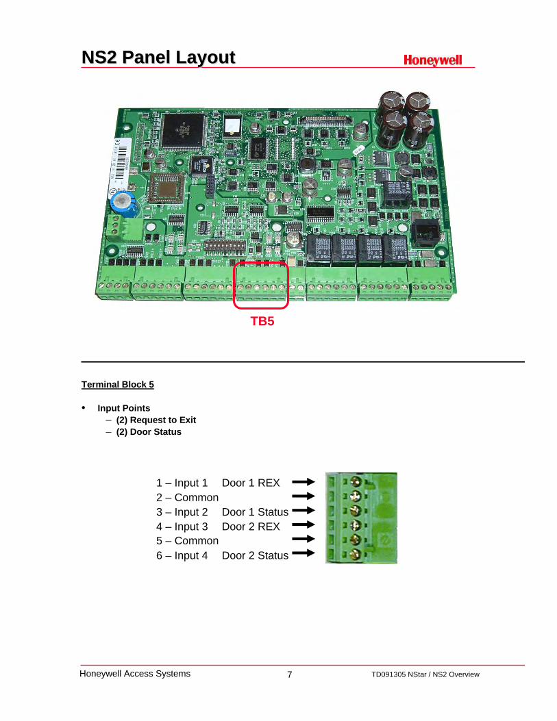
NS2 Panel LayoutNS2 Panel Layout
Terminal Block 5
• Input Points– (2) Request to Exit– (2) Door Status
TB5
1 – Input 1 Door 1 REX2 – Common3 – Input 2 Door 1 Status4 – Input 3 Door 2 REX5 – Common6 – Input 4 Door 2 Status

8 TD091305 NStar / NS2 OverviewHoneywell Access Systems
NS2 Panel LayoutNS2 Panel Layout
Terminal Block 6
• Auxiliary Power Output– 600mA @ 12 VDC
• Peripheral Devices– PIR– Egress Buttons– Auxiliary Relays– Additional Reader Power
• Not intended for Door Locks
TB6
AUX +12VDCAUX COM
9 TD091305 NStar / NS2 OverviewHoneywell Access Systems
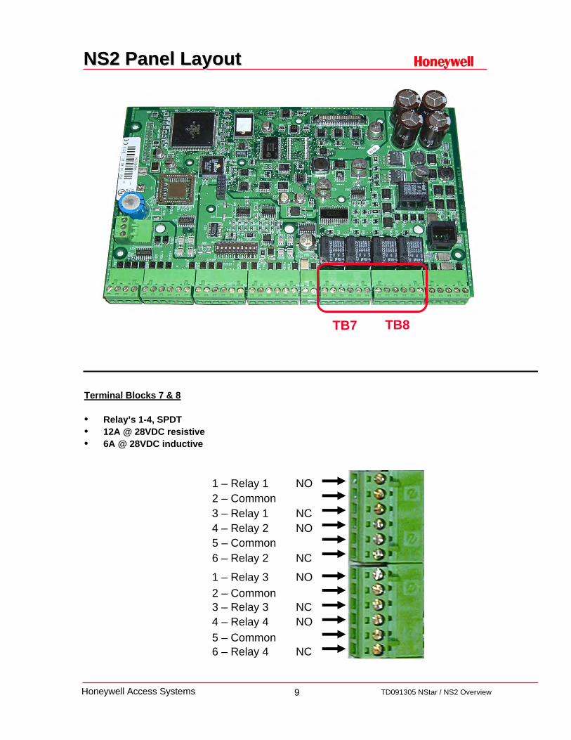
NS2 Panel LayoutNS2 Panel Layout
Terminal Blocks 7 & 8
• Relay’s 1-4, SPDT• 12A @ 28VDC resistive• 6A @ 28VDC inductive
TB8TB7
1 – Relay 1 NO2 – Common3 – Relay 1 NC4 – Relay 2 NO5 – Common6 – Relay 2 NC
1 – Relay 3 NO2 – Common3 – Relay 3 NC4 – Relay 4 NO5 – Common 6 – Relay 4 NC
10 TD091305 NStar / NS2 OverviewHoneywell Access Systems
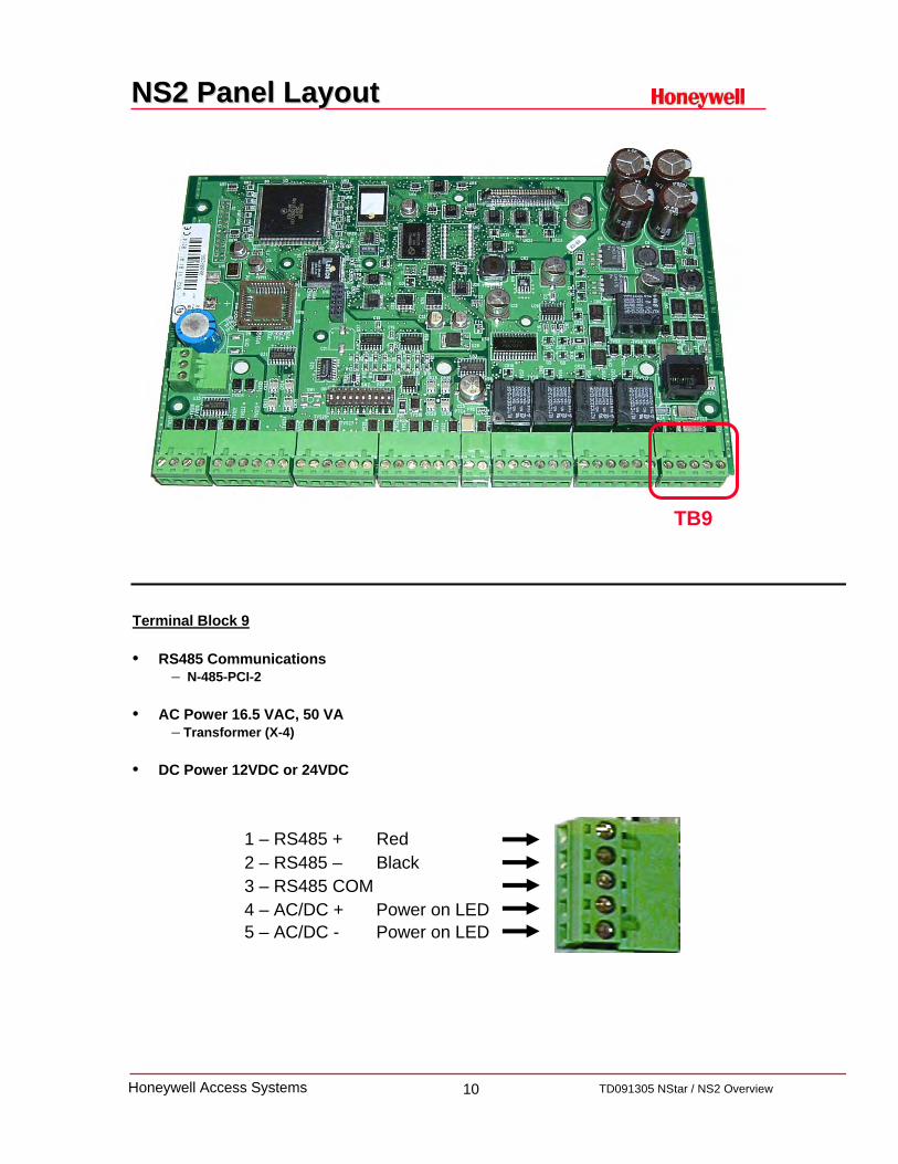
NS2 Panel LayoutNS2 Panel Layout
Terminal Block 9
• RS485 Communications– N-485-PCI-2
• AC Power 16.5 VAC, 50 VA – Transformer (X-4)
• DC Power 12VDC or 24VDC
TB9
1 – RS485 + Red2 – RS485 – Black3 – RS485 COM4 – AC/DC + Power on LED5 – AC/DC - Power on LED

11 TD091305 NStar / NS2 OverviewHoneywell Access Systems
NS2MEM Memory Expansion Board NS2MEM Memory Expansion Board
• The NS2MEM module is a "Plug and Play" memory board that attaches to the "Xport" and allows memory expansion of up to 10,000 cards and 100,000 events.
• NOTE: – The NS2MEM module is ONLY SUPPORTED WITH NS2 FIRMWARE VERSION
1.03.09 OR HIGHER.

12 TD091305 NStar / NS2 OverviewHoneywell Access Systems
Communications OptionsCommunications Options
RS-232:• Default Method• Direct connection using CBL50 50 foot cable• 1 panel per RS-232 connection• Only computer RS-232 communication ports 1 and/or 2 are supported
RS-485:• On-board connection to panels via 485-PCI-2 module• 31 panel maximum per RS-485 connection• Only computer RS-232 communication ports 1 and/or 2 are supported
NSLAN1:• Add on module• Onboard connector provides Ethernet to serial interface using existing Ethernet devices • Can be programmed remotely using Telnet• Requires a static (fixed) IP address• 1 IP address per NSLAN1 per panel; 64 maximum IP connections
RS-232 Port
NSLAN1
RS-485 connection

13 TD091305 NStar / NS2 OverviewHoneywell Access Systems
BASIC NS2 COMMUNICATION BASIC NS2 COMMUNICATION ANDAND
PANEL CONFIGURATIONSPANEL CONFIGURATIONS

14 TD091305 NStar / NS2 OverviewHoneywell Access Systems
Serial Communications Serial Communications

15 TD091305 NStar / NS2 OverviewHoneywell Access Systems
RSRS--485 Communications485 Communications
16 TD091305 NStar / NS2 OverviewHoneywell Access Systems
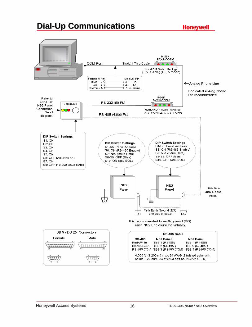
DialDial--Up Communications Up Communications

17 TD091305 NStar / NS2 OverviewHoneywell Access Systems
HUB
100BaseT (CAT 5) 100 Ft. Max.
RJ-45
LANSRLU1
Refer to LANSRLU1
documentationfor programmig.
N-485-PCI-2L
100 Ft. Max.
NIC
RS-232 (50 Ft.)
Refer to
ConnectionDetail
diagram.
DIP Switch SettingsS1: ONS2: ONS3: ONS4: ONS5: ONS6: OFF (Ack/Nak on)S7: ONS8: OFF (19,200 Baud Rate)
Panel Panel
EGOnly Earth Ground (EG)
one side of cable.EG EG
EG
DIP Switch SettingsS1-S5: Panel AddressS6: ON (RS-485 Enable)S7: N/A (Baud Rate)S8-S9: OFF (Bias)S10: ON (485 EOL)
DIP Switch SettingsS1-S5: Panel AddressS6: ON (RS-485 Enable)S7: N/A (Baud Rate)S8-S9: OFF (Bias)S10: OFF (485 EOL)
See RS-485 Cable
note.
100BaseT(CAT 5)
NS2 Panel485-PCI /
It is recommended to earth ground (EG) each NS2 enclosure individually.
NS2NS2
EG
NSLAN1installed
NS2Panel
NSLAN1 must be programmed with a
static IP addressSee NSLAN1 product
documentation for programing instructions.
DIP Switch SettingsS1-S5: Panel AddressS6: OFF (RS-485 Disable)S7: ON (57,600 Baud Rate)S8-S10: OFF
Ethernet Communications Ethernet Communications

18 TD091305 NStar / NS2 OverviewHoneywell Access Systems
For complete wiring guidelinesFor complete wiring guidelinesplease review the please review the
““NS2 Configuration GuideNS2 Configuration Guide””

19 TD091305 NStar / NS2 OverviewHoneywell Access Systems
NSTAR SOFTWARE OVERVIEWNSTAR SOFTWARE OVERVIEW

20 TD091305 NStar / NS2 OverviewHoneywell Access Systems
Minimum PC Requirements: This setup is sufficient for small systems with 1 to 10 readers, up to 250 cards, and 2 communication ports. While this is a good configuration for a workstation, it is not sufficient for use as a server.
Pentium III-700Mhz CPU512 megabytes of RAM2.1 gigabyte hard diskTwo serial communication portsTape backup driveOne parallel port (badging to be done on workstation)15" SVGA color monitor (1024 x 768, 256 color)Supported operating systems:Microsoft Windows 2000 sp4, Windows XP Professional sp1, Windows XP Professional sp2
(build 45 or higher), Windows 2003 server (build 45 or higher)
Recommended PC Configuration: This is the recommended hardware configuration for a basic access control, including badging and alarm monitoring.It can be used for a stand-alone system, a workstation or a server.Additional RAM and will improve performance.
Pentium IV-1 GHz CPU512 megabytes of RAM6 gigabyte hard disk2 serial communication ports8 gigabyte tape backup1 parallel port (2 for badging)17" 1024 x 768 true color monitorSupported operating systems:Microsoft Windows 2000 sp4, Windows XP Professional sp1, Windows XP Professional sp2
(build 45 or higher), Windows 2003 Server (build 45 or higher)
Software PC Specifications Software PC Specifications

21 TD091305 NStar / NS2 OverviewHoneywell Access Systems
Software InstallationSoftware Installation
BEFORE installing the NStar software, ensure that the following conditions are met:
• Verify you have local System Administrator rights on the local PC you are installing the software on (this is only needed for installation purposes, and not client / user access)
• Verify supported operating system: Microsoft Windows 2000 sp4, Windows XP Professional sp1, Windows XP Professional sp2 (build 45 or higher), Windows 2003 Server (build 45 or higher)
• Install any video capture card or digital camera on the PC that will serve as the badging workstation.
• Ensure that networked computers are communicating with one another. (Can the NStar server see the client, and vice-versa.)
• Ensure that machine names use only alphanumeric characters without spaces, and that the first character is always alpha (i.e. standard UNC connections)
• To upgrade from build 19 or earlier, make a backup prior to uninstalling the NStar software. After installation of new software, restore backed up database to current software.
• MSDE 2000 is the provided database engine for NStar build 45 or higher. Verify it will not conflict with an earlier version of MSDE or SQL on the PC that will become the NStar Database Server.
22 TD091305 NStar / NS2 OverviewHoneywell Access Systems
Software Installation Software Installation –– File PathFile Path
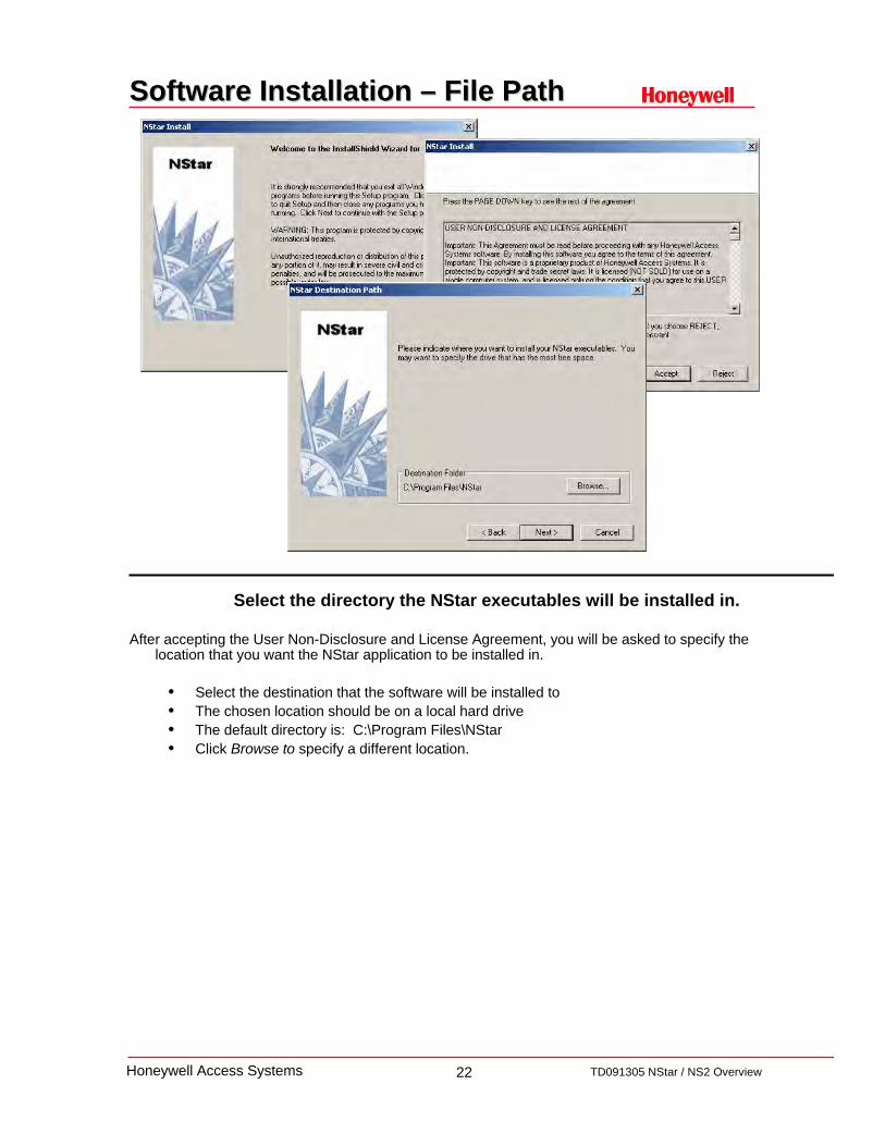
Select the directory the NStar executables will be installed in.
After accepting the User Non-Disclosure and License Agreement, you will be asked to specify the location that you want the NStar application to be installed in.
• Select the destination that the software will be installed to• The chosen location should be on a local hard drive• The default directory is: C:\Program Files\NStar• Click Browse to specify a different location.

23 TD091305 NStar / NS2 OverviewHoneywell Access Systems
Software Installation Software Installation –– File PathFile Path
Select the directory where the Database and Badging components will be installed.
Database Data File Path:The physical location the database will be stored in.Default is C:\MSSQL7\DataClick Browse to specify a different location.
Cardholder Image Files:The physical location the Card Holder Photos will be stored in.The default is C:\Program Files\NStar\Database\UserImageClick Browse to specify a different location.
Badge Image Files:The physical location the badge artwork will be stored in.The default is C:\Program Files\NStar\Database\BadgeImageClick Browse to specify a different location.
24 TD091305 NStar / NS2 OverviewHoneywell Access Systems
Software Installation Software Installation –– Install TypeInstall Type
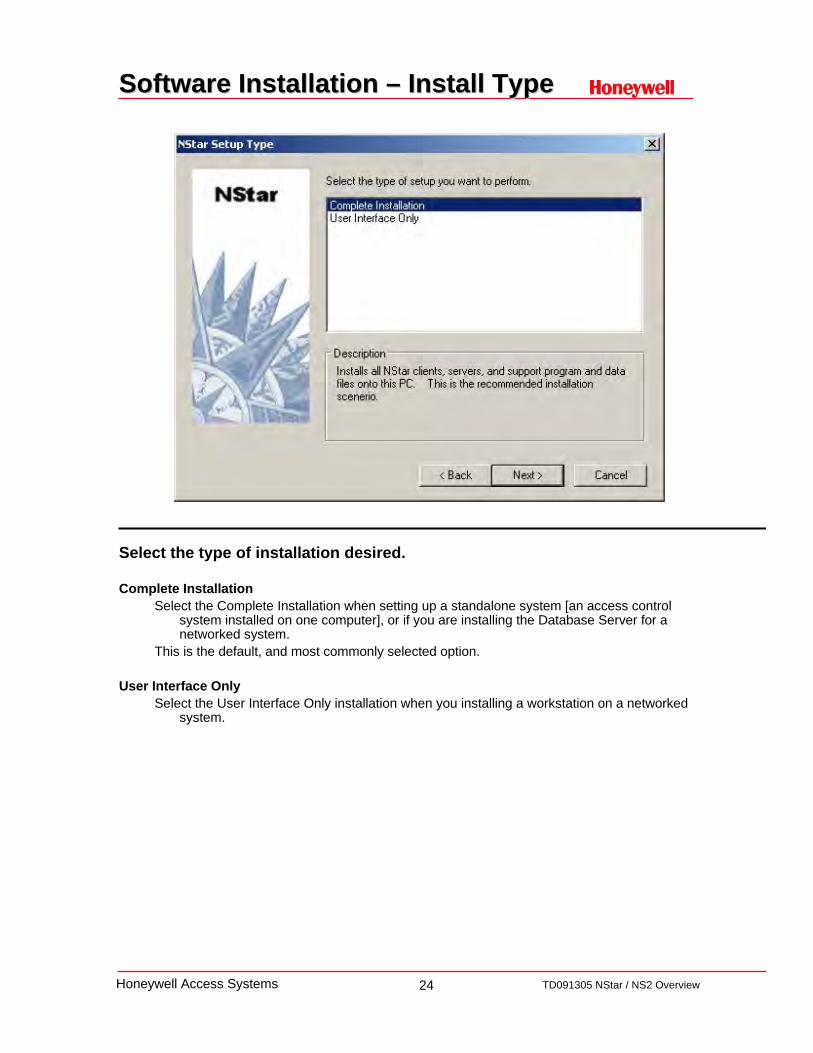
Select the type of installation desired.
Complete InstallationSelect the Complete Installation when setting up a standalone system [an access control
system installed on one computer], or if you are installing the Database Server for a networked system.
This is the default, and most commonly selected option.
User Interface OnlySelect the User Interface Only installation when you installing a workstation on a networked
system.

25 TD091305 NStar / NS2 OverviewHoneywell Access Systems
Software Installation Software Installation –– CD KeyCD Key
Fill in the User Information
• The Name and CD Key fields must be filled in.• The Company field is optional.• The CD Key number is located on the inside front cover of the software case.

26 TD091305 NStar / NS2 OverviewHoneywell Access Systems
Software InstallationSoftware Installation
Desktop IconsShould the NStar icons be placed on the desktop?Select Yes to create NStar icons on the PC desktopSelect No to skip creating NStar icons on the PC desktop.
Database Installation ModeChoose whether to connect the database engine to the database file automatically or
manually.Unless you are a database / software expert, it is highly recommended to choose the
automatic installation option.
Stop DatabaseSelect Yes to continue the installation. (Other MSDE/SQL databases located on this PC
could be affected)Select No to exit and stop the installation.
27 TD091305 NStar / NS2 OverviewHoneywell Access Systems
Software InstallationSoftware Installation
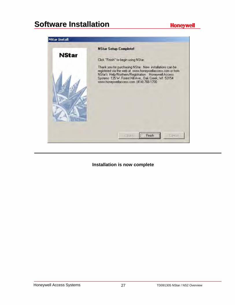
Installation is now complete

28 TD091305 NStar / NS2 OverviewHoneywell Access Systems
NStar Service ManagerNStar Service Manager
NStar Service ManagerThe NStar Service Manager is a utility which allows the administrator or operator to easily
start and stop the software services. The installed program components are listed, and the Status column indicates whether or
not each is running.Select the service or services click then click Start or Stop as necessary.The Database service must be the first service started and the last one stopped
SQL Server Service ManagerThe SQL Service Manager is a utility which allows the administrator or operator to easily
start and stop the SQL / MSDE services. To check if the MSQL components are running, double click on the icon (shown to the left) in
the tray on the bottom of the Window.The message on the bottom of the SQL Server Service Manager windows will give you the
computer name followed by the status of the service.

29 TD091305 NStar / NS2 OverviewHoneywell Access Systems
NStar System ManagerNStar System Manager
The System Manager is a utility used by NStar to locate its various software components.
Generally, none of the settings on the System Manager should be changed.
User Interface Tab: Used only when a client installation is performed on a remote machine.
RPC Security options Tab: Select either Domain or Workgroup Environment (If unknown, Workgroup is recommended)
Database Server Tab settings: Location of the RPC endpoint and the Database password.
Database Archive Server Tab settings: Location of the RPC endpoint and Archive Database password.
Schedule Server Tab settings: Node Name or IP address of the Database Server if Schedule Server is located on a different machine
Communications Server Tab settings: Node Name or IP address of the Communications Server if the Database Server is located on a different machine.

30 TD091305 NStar / NS2 OverviewHoneywell Access Systems
System Manager System Manager –– RPC optionsRPC options
NStar works both in Domain and Workgroup environment.
Domain Environment: Select the Domain Environment radio button to set the option to Domain Environment.
Workgroup Environment: Select the Workgroup Environment radio button to set the option to Workgroup Environment.
Additional Information:
• The user can set the option as per the requirement, however, by default, the option is set to DOMAIN Environment.
• This setting needs to match between all Servers and all clients.• You need to restart the Servers and UI client, in case of any change in the setting. The
setting changes cannot take effect dynamically.• If unsure of which option to select, it is recommended that “Workgroup” be selected.

31 TD091305 NStar / NS2 OverviewHoneywell Access Systems
ADV – Abstract Device
The abstract device (ADV) plays an important role in the design of your system. It provides a user interface for controlling different hardware, without concerning the end user with the details of the hardwareconfiguration, just as a desktop icon does within the Windows operating system. It is a logical representation of a physical device. Similar in appearance to an icon, an ADV is associated with an actual device in your access control system.
Name: Enter the name of the ADV. (This will be the name you see in all list trees)
Action Group: A template that defines the priority of a given event related to the device.When an Action Group template is edited, all ADVs associated with it are changed,
globally.
Action Group Name: Enter the name of the Action Group
Action: Select an Action from the list
Priority: Set the Priority you want assigned to the selected Action.
Write to History: Select the Write to History option if you want the event written to the history file.
Additional Information: Most ADV programming is done by entering the ADV Name and pressing the Enter key.

32 TD091305 NStar / NS2 OverviewHoneywell Access Systems
CONFIGURATION
TIMEMANAGEMENT
SCHEDULE
TIMEZONEHOLIDAY
DEFINE ACCESS AREA
CONTROL AREA
CONFIGURATION
DEVICEDEVICE
MAP
CONFIGURATION
ACCESS LEVEL
CARD HOLDER
CARD
SEND TIME & DATE
ACTIVATE & DEACTIVATE CARDS
UPDATE CUSTOM ACCESS LEVELS
PANELCOM DEVICE
COMMUNICATIONS SERVER
SCHEDULESERVER
No Quick Start Wizard
Using the Quick Start Wizard
Recommended Programming OrderRecommended Programming Order

33 TD091305 NStar / NS2 OverviewHoneywell Access Systems
Log inLog in
All services should be running prior to logging in, but if not, double-click the NStar Services icon and start all services.
Double-click the NStar User Interface icon, the User Interface opens and the Connect to Server window is displayed.
Enter Admin as the default operator Name.
NOTE: No password is required for the initial log in, but you should add a password in order to insure the security of your system.

34 TD091305 NStar / NS2 OverviewHoneywell Access Systems
Quick Start Wizard
The Quick Start Wizard is an optional interface and a good starting point for users unfamiliar with the NStar software, however it can also help an experienced user to program the system in a shorter period of time.
The Quick Start Wizard is initially configured so that it automatically starts whenever you run NStar.
In addition, any settings configured by QSW can be changed using the core program after the wizard is finished.
Follow through the steps in QSW to configure options in a sequential order, however, you can select any option at any time and configure accordingly.
The QSW can also be found in the Configuration Menu if it does not start after login.

35 TD091305 NStar / NS2 OverviewHoneywell Access Systems
QSW – Time Zones
Select the necessary Time Zones to be included in the configuration then click “NEXT”
Time Zones are a range of hours and days that include a start and end time and days on which they are valid. They can be used to unlock doors, allow access, or even run scheduled events.
Time Zones can be modified later in the Time Zone database screen
36 TD091305 NStar / NS2 OverviewHoneywell Access Systems
QSW – Add new Loop
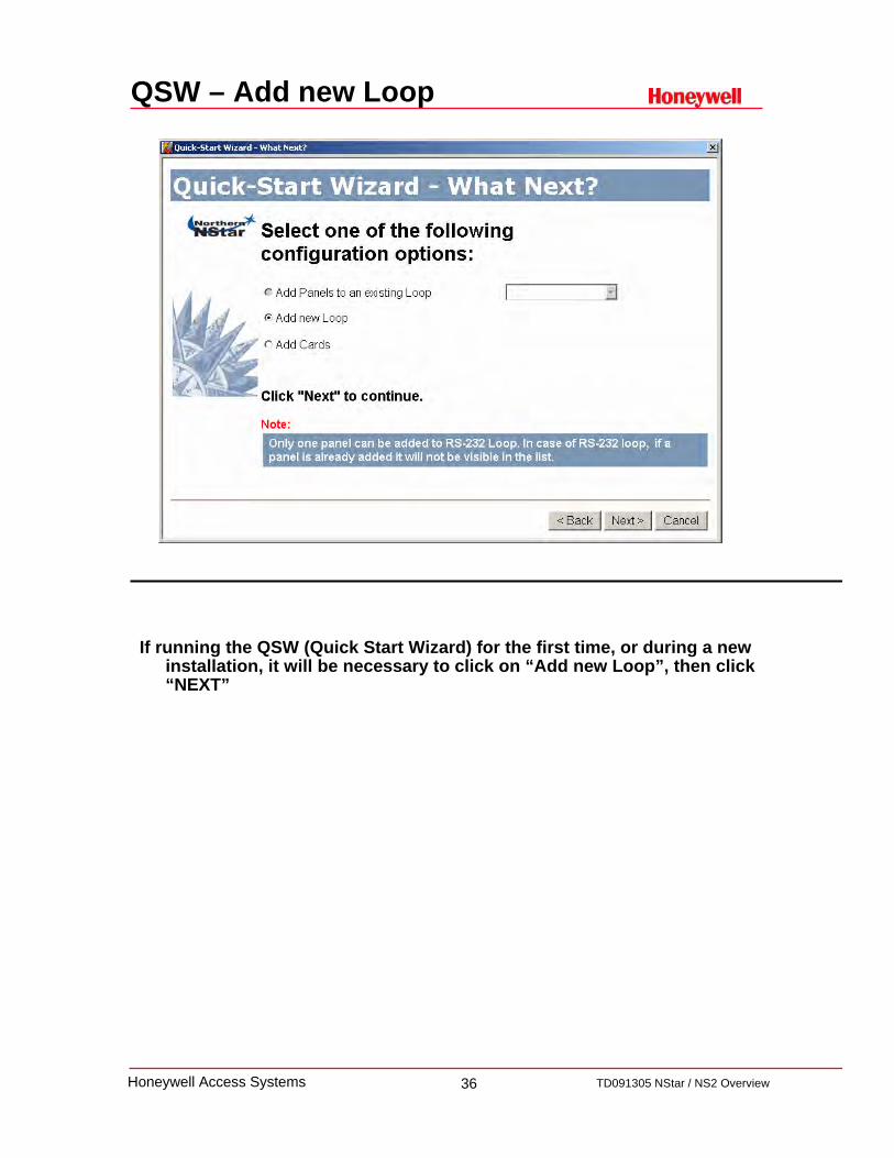
If running the QSW (Quick Start Wizard) for the first time, or during a new installation, it will be necessary to click on “Add new Loop”, then click “NEXT”

37 TD091305 NStar / NS2 OverviewHoneywell Access Systems
QSW – Select COM Port
After verifying the correct operating system in use, select the Communications Port that you will be connecting your panel to.
Note: Only TCP/IP and COM 1 & COM 2 are supported in the NStar software

38 TD091305 NStar / NS2 OverviewHoneywell Access Systems
QSW – Select COM Loop
Select the type of device you will be using to connect to your panel then click “NEXT”
Communication interfaces to panels are programmed by adding them to an existing communication server on the Device Map.
There must be a communication port, IP address or modem available for each communication interface.
RS-232 Port: Direct connection to an NS2 panel using 50ft CBL50.• 1 NS2 per COM port or IP address• Only TCP/IP and COM port 1 & 2 are supported for connectionsNote: If using TCP/IP (NSLAN1) only 64 connections permissible.
Panel Loop: Direct wire of RS-485 PCI connection a loop of 31 NS2 panels.• 31 panel maximum per RS-485 connection• Only TCP/IP and COM port 1 & 2 supported for connections

39 TD091305 NStar / NS2 OverviewHoneywell Access Systems
QSW – Loop Name
Provide a name for this hardware connection (loop) then click “NEXT”

40 TD091305 NStar / NS2 OverviewHoneywell Access Systems
QSW – Panel Address
Select the panel Address, then click “NEXT”

41 TD091305 NStar / NS2 OverviewHoneywell Access Systems
QSW – Panel Type
Select the type of panel you are using, then click “NEXT”

42 TD091305 NStar / NS2 OverviewHoneywell Access Systems
QSW – Panel Name
Type the name of the panel (be as descriptive as possible), then click “NEXT”

43 TD091305 NStar / NS2 OverviewHoneywell Access Systems
QSW – Reader Name
Type the name of the readers associated with this panel (be as descriptive as possible), then click “NEXT”

44 TD091305 NStar / NS2 OverviewHoneywell Access Systems
QSW – Reader Time Zones
Select the time zone to be associated with each reader, then click “NEXT”
Note that the door will remain unlocked during the selected time period
45 TD091305 NStar / NS2 OverviewHoneywell Access Systems
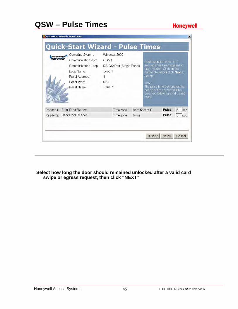
QSW – Pulse Times
Select how long the door should remained unlocked after a valid card swipe or egress request, then click “NEXT”

46 TD091305 NStar / NS2 OverviewHoneywell Access Systems
QSW – What Next
Select “Finished with Hardware Configuration” then click “NEXT”

47 TD091305 NStar / NS2 OverviewHoneywell Access Systems
QSW – Add Cards
Cards and Card Holder information will be added later during theinstallation, so select “Not at this time” then click “NEXT”

48 TD091305 NStar / NS2 OverviewHoneywell Access Systems
QSW – Complete Configuration
Click on Next, then Finish to complete programming with the QSW
49 TD091305 NStar / NS2 OverviewHoneywell Access Systems
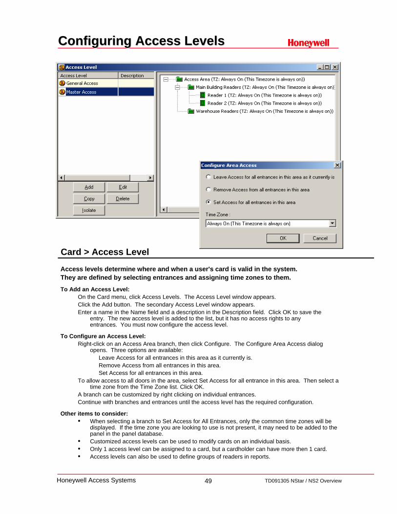
Configuring Access LevelsConfiguring Access Levels
Access levels determine where and when a user's card is valid in the system. They are defined by selecting entrances and assigning time zones to them.
To Add an Access Level:On the Card menu, click Access Levels. The Access Level window appears.Click the Add button. The secondary Access Level window appears.Enter a name in the Name field and a description in the Description field. Click OK to save the
entry. The new access level is added to the list, but it has no access rights to any entrances. You must now configure the access level.
To Configure an Access Level:Right-click on an Access Area branch, then click Configure. The Configure Area Access dialog
opens. Three options are available:Leave Access for all entrances in this area as it currently is.Remove Access from all entrances in this area.Set Access for all entrances in this area.
To allow access to all doors in the area, select Set Access for all entrance in this area. Then select a time zone from the Time Zone list. Click OK.
A branch can be customized by right clicking on individual entrances.Continue with branches and entrances until the access level has the required configuration.
Other items to consider:• When selecting a branch to Set Access for All Entrances, only the common time zones will be
displayed. If the time zone you are looking to use is not present, it may need to be added to the panel in the panel database.
• Customized access levels can be used to modify cards on an individual basis.• Only 1 access level can be assigned to a card, but a cardholder can have more then 1 card.• Access levels can also be used to define groups of readers in reports.
Card > Access Level

50 TD091305 NStar / NS2 OverviewHoneywell Access Systems
Add a CardholderAdd a Cardholder
Card holders are the people to whom cards can be issued to. The Card Holder Database contains card holder information, card numbers and badging photos
on all the card holders that have been entered into the system. Photos can be added to the card holder information either by capturing video images or importing
digital files created in other programs, for example scanned images or photos taken with a digital camera.
To add a Card Holder:Click the card holder button or click Card Holder in the Card menu.The Card Holder database dialog appears.Click Add to activate the record view.On the first tab, enter the card holder's First and Last Name. This is the minimum
information required to add a card holder. If you click OK at this point, the new card holder is added without any cards being attached.
To associate a photo or signature with the badge:In the Card Holder’s record, click the Card Biometrics TabClick Capture or Import from the Card Biometrics tab to open the Capture Image window.
If Importing a photo, navigate to the folder containing your photo files, select the correct file and click Open.
If Capturing a live image, click Freeze, to capture the live image. Once the picture is frozen or captured, adjustments as needed.
Click OK to close Image dialog and the photo appears in the Card Biometrics tab.
Note: System must be upgraded with NSOPT1 for photo badging option to function.
Card > Card Holder

51 TD091305 NStar / NS2 OverviewHoneywell Access Systems
Add a card to the CardholderAdd a card to the Cardholder
Cards are physical credentials that are presented to a reader when access to a door is requested.
A card must have a valid access level in order to unlock a specified door. The Card Holder Database contains all card information via the Cards Tab.
To assign an existing card to a Card Holder:While adding or editing a card holder, click the Cards tab, then click Attach to issue a card which
is already entered in the Card database. If no existing cards are displayed, you must add a new card.
To assign a new card to a Card Holder:Click the Cards tab, and the Card database record view opens. In the Card menu, click Card and the Card window appears. Click Add and enter the Card Number (required).Select an Access Level from the Access Level list (required).By default, a card has an Inactive status as soon as it is entered into the system, and must be
made Active if it is to be used in the system.If you want to select an activation date, click Change from the Activation Date area. If you want the card to be valid for a limited time, click Change from the Expiration Date area. To associate a badge layout with the card, click the Badge tab. Select a Badge Front and Badge
Back Use the Custom Access Level option to set a custom [usually limited] access level for the card.Action groups can be used to set specific actions to occur when a card is read in different states,
for example when its status is Lost/Stolen or Trace rather than Active.Once the card has been defined, click OK and you will return to the Card Holder database.When you have finished, click OK to save the new card. Or, click Cancel to return to the Card
database window without saving the new card.
Card > Card Holder

52 TD091305 NStar / NS2 OverviewHoneywell Access Systems
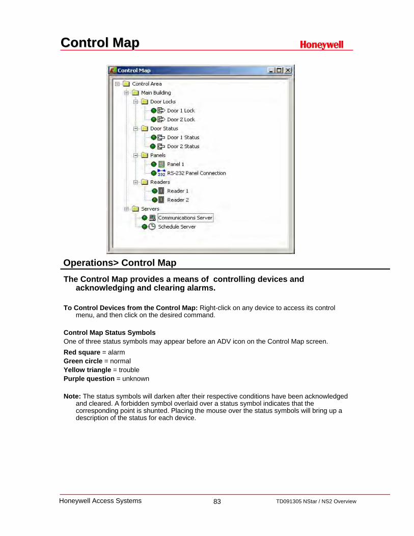
Control MapControl Map
The Control Map provides a means of controlling devices and acknowledging and clearing alarms.
To Control Devices from the Control Map: Right-click on any device to access its control menu, and then click on the desired command.
Control Map Status SymbolsOne of three status symbols may appear before an ADV icon on the Control Map screen.Red square = alarmGreen circle = normalYellow triangle = troublePurple question = unknown
Note: The status symbols will darken after their respective conditions have been acknowledged and cleared. A forbidden symbol overlaid over a status symbol indicates that the corresponding point is shunted. Placing the mouse over the status symbols will bring up a description of the status for each device.
Operations> Control Map
53 TD091305 NStar / NS2 OverviewHoneywell Access Systems
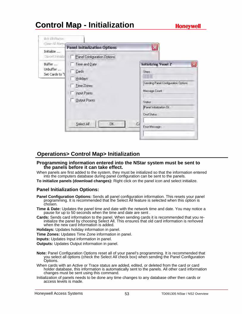
Control Map Control Map -- Initialization
Programming information entered into the NStar system must be sent to the panels before it can take effect.
When panels are first added to the system, they must be initialized so that the information entered into the computers database during panel configuration can be sent to the panels.
To initialize panels (download changes): Right click on the panel icon and select initialize.
Panel Initialization Options:Panel Configuration Options: Sends all panel configuration information. This resets your panel
programming. It is recommended that the Select All feature is selected when this option is chosen.
Time & Date: Updates the panel time and date with the network time and date. You may notice a pause for up to 50 seconds when the time and date are sent .
Cards: Sends card information to the panel. When sending cards it is recommended that you re-initialize the panel by choosing Select All. This ensures that old card information is removed when the new card information is added.
Holidays: Updates holiday information in panel.Time Zones: Updates Time Zone information in panel.Inputs: Updates Input information in panel.Outputs: Updates Output information in panel.
Note: Panel Configuration Options reset all of your panel’s programming. It is recommended that you select all options (check the Select All check box) when sending the Panel Configuration Options.
When cards with an Active or Trace status are added, edited, or deleted from the card or card holder database, this information is automatically sent to the panels. All other card information changes must be sent using this command.
Initialization of panels needs to be done any time changes to any database other then cards or access levels is made.
Operations> Control Map> Initialization

54 TD091305 NStar / NS2 OverviewHoneywell Access Systems
ADVANCED PROGRAMMINGADVANCED PROGRAMMING

55 TD091305 NStar / NS2 OverviewHoneywell Access Systems
System DefaultsSystem Defaults
System Defaults settings are global. Rarely will you need to change the defaults values however if in doubt, leave the default.
Defaults TabGrant all operators access: Make available to all operators those ADVs not in Control Areas.Maximum Length of Card Numbers: Select the largest card number handled by the software. Allow only numeric Card Numbers: The default for this option is Selected.
Alarm Handling Tab - Options that affect how alarms will be handled within the system. Auto Popup Alarm View Window: Allows the Alarm View to open or restore view [if minimized] when
a new alarm is received and displayed in the Alarm View.Beep Until Alarm Acknowledged: This setting ensures that an alarm will beep from the PC’s speaker
until it is acknowledged.Do Not Close Window Until all Alarms are Acknowledged: Requires the operator to acknowledgeall alarms before closing the Alarm View window.Reissue Uncleared Alarms: Selected alarms that are acknowledged but not cleared will be reissued.Require a Response when Acknowledging Alarms: Requires the operator to add a note before
acknowledging an alarm.Automatically Clear Acknowledged Alarms: Automatically clears alarms when they are
acknowledged.Clear Alarm on Normal Only: Alarms can only be cleared when the source of the alarm returns to a
normal state.Maximum # of events in view: The default setting allows for 1,000 of the most recent events to bedisplayed in the event viewer.Auto-clear alarm limit (per point): The default setting allows for 100 of the most recent alarm events
per point to be displayed in the Alarm View.Auto-clear card reads limit (per door): The default setting allows for 100 of the most recent card
events per door to be displayed in the alarm view.
File > System Defaults

56 TD091305 NStar / NS2 OverviewHoneywell Access Systems
Workstation DefaultsWorkstation Defaults
Workstation Defaults settings are unique to the workstation the User Interface is loaded on. Rarely will you need to change the defaults values however if in doubt, leave the default.
Maximum Records returned from the Database for Selecting List: This is the maximum number of records that will be retrieved and displayed in selection lists. The default for this field is 200.
Maximum Records returned from the Database for Find List: The maximum number of records retrieved from a database when a "Find" is conducted. The default is 20.
Confirm Card Deletes: If this option is selected, you will be prompted to confirm a card delete before it is removed from the database. The default for this field is Selected.
Always Show Record View: If this option is selected, when a database window opens, the record view or detail view will open at the same time. The default for this field is Unselected.
Freeze Client: If the Freeze Client option is selected, access to the User Interface is frozen after a set period of operator inactivity (from 1 to 60 minutes). The default for this field is Unselected. If you do select Freeze Client, click the up or down arrows to the right of the Wait field to set the number of minutes; the default is 10 minutes. Once the client is frozen, an operator will have to log back in to use the program.
File > Workstation Defaults
57 TD091305 NStar / NS2 OverviewHoneywell Access Systems
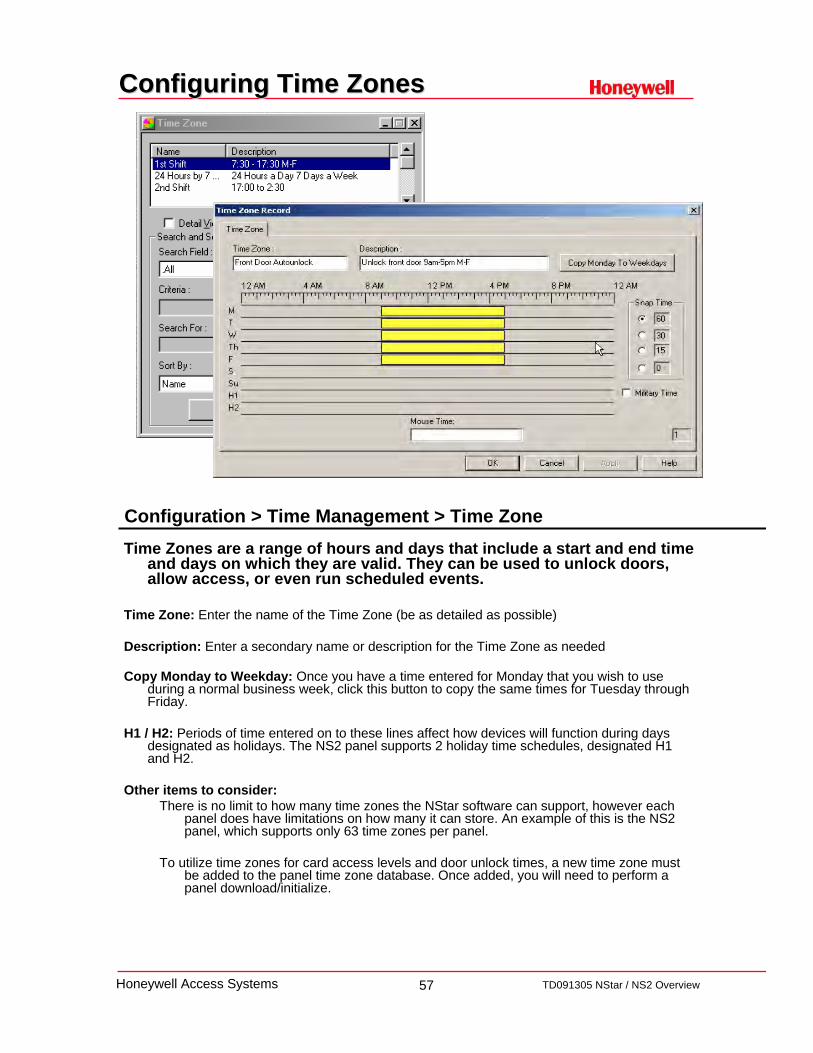
Configuring Time ZonesConfiguring Time Zones
Time Zones are a range of hours and days that include a start and end time and days on which they are valid. They can be used to unlock doors, allow access, or even run scheduled events.
Time Zone: Enter the name of the Time Zone (be as detailed as possible)
Description: Enter a secondary name or description for the Time Zone as needed
Copy Monday to Weekday: Once you have a time entered for Monday that you wish to use during a normal business week, click this button to copy the same times for Tuesday through Friday.
H1 / H2: Periods of time entered on to these lines affect how devices will function during days designated as holidays. The NS2 panel supports 2 holiday time schedules, designated H1 and H2.
Other items to consider: There is no limit to how many time zones the NStar software can support, however each
panel does have limitations on how many it can store. An example of this is the NS2 panel, which supports only 63 time zones per panel.
To utilize time zones for card access levels and door unlock times, a new time zone must be added to the panel time zone database. Once added, you will need to perform a panel download/initialize.
Configuration > Time Management > Time Zone

58 TD091305 NStar / NS2 OverviewHoneywell Access Systems
Configuring HolidaysConfiguring Holidays
A Holiday Group is a collection of holiday definitions. These definitions tell the panel that there are exceptions to the standard schedules.
Some holidays [New Years Day] occur on the same date every year, while others occur on a different date each year. In the course of defining Holiday Groups, you can indicate if a holiday occurs on the same date every year.
Name: Enter the name of the holiday
Date: Select the date to be used to represent the holiday
Apply to all years: Will this holiday occur each year on the same date? If so, check the check box
Holiday 1 / Holiday 2: Select which Holiday this will represent. As an example, New Years Eve vs New Years Day where there may be different hours of operation for each day, so Holiday 1 (New Years Eve) and Holiday 2 (New Years Day).
Other items to consider: Once a holiday group has been defined, it is associated with a panel to allow for a change in access on holidays. If you have Time Zones in a panel that have holidays defined, you must have a Holiday Group assigned to that panel.
Note: After adding or modifying Holiday Groups, the panel must be initialized.
Configuration > Time Management > Holiday Group

59 TD091305 NStar / NS2 OverviewHoneywell Access Systems
Configuring SchedulesConfiguring Schedules
Schedules are used to perform predefined events at a predetermined times.
Schedule Name: Enter the name of the Schedule (be as detailed as possible)
Type: Select the type of schedule to be run
Frequency: How often is this schedule to run?
Dial Remote Area: What events will occur when dialing a remote site via dial-up modem
Next scheduled date and time: The date the schedule will next run
Hour & Minute: The time that the schedule will next run
Other items to consider: Schedules are dependent on the NStar Schedule Server. This service which must be running for schedules to take affect will need to be added to the Device Map.
Note: If the Quick Start Wizard has been used to initially configure the system, the Schedule Server has already been added.
If the Quick Start Wizard has not been used been used to initially configure the system, add the Schedule Server Service in the Control Map, then stop and restart the Schedule Server Service in the NStar Service Manager.
Configuration > Time Management > Schedules

60 TD091305 NStar / NS2 OverviewHoneywell Access Systems
Configuring Device MapConfiguring Device Map
Within the Device Map, each physical device to be used within the NStar access control system is created and defined.
Device Map: Devices must be defined and added to the system via the Device Map.Devices include communication hardware, servers, panels and readers.
Device Map: Right Click on Device to add additional components
Configuration > Device > Device Map

61 TD091305 NStar / NS2 OverviewHoneywell Access Systems
Configuring Com Server Configuring Com Server –– Basic InfoBasic Info
The Communication Server is a branch on the Device Map that defines your active communication ports
Name: The name of computer managing communications. This could be the same server that is hosting the installation of NStar or any computer designated by the site.
Description: Alternate name for the Communication server.
Machine Name: By default, this is the name of the server the Communications Server Service is running on. To change, either retype the PC name or IP Address, or click on the little box to open the Windows computer selection window, find the computer from the list of available computers and click OK to return to this window.
Alarm priority for notification: All alarms need to have an equal or lower value for the alarm to be seen on the event monitor window. If an alarm is given a number higher than the one entered, the alarm will not be seen and will not be stored on in history.
Alarm Priority for required for Acknowledgement: Once a value is entered, all alarms with a value between 1 and the number entered will be required to be acknowledged in the Alarm Monitor window. Any alarm with a value higher that the number given and the number for notification will be seen in the Alarm monitor window and history reports.
Note: The suggested default value of 50 should be used when the NSOPT1 is purchased and activated.
Write Transaction to File? Used by Tech Support for troubleshooting.
Configuration > Device > Device Map > Add Com Server

62 TD091305 NStar / NS2 OverviewHoneywell Access Systems
Configuring Com ServerConfiguring Com Server-- Ports TabPorts Tab
Ports: Select the port the system will be hardwired to.• Note that NStar only supports TCP/IP and COM Port 1 & 2 only
Other items to consider:• NStar supports only one Communication Servers
• NStar creates and uses a specific Windows Service for (Communications Server) Communications. If you need to use Hyper Terminal, you will need to stop the NStar Com Server prior to using Hyper Terminal.
• If using an IP address, contact site IT department for a static IP address to use for the Server and any panels.
63 TD091305 NStar / NS2 OverviewHoneywell Access Systems
Adding a Com LoopAdding a Com Loop
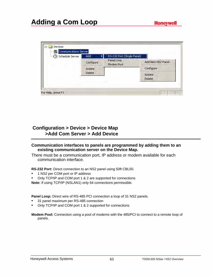
Communication interfaces to panels are programmed by adding them to an existing communication server on the Device Map.
There must be a communication port, IP address or modem available for each communication interface.
RS-232 Port: Direct connection to an NS2 panel using 50ft CBL50.• 1 NS2 per COM port or IP address• Only TCP/IP and COM port 1 & 2 are supported for connectionsNote: If using TCP/IP (NSLAN1) only 64 connections permissible.
Panel Loop: Direct wire of RS-485 PCI connection a loop of 31 NS2 panels.• 31 panel maximum per RS-485 connection• Only TCP/IP and COM port 1 & 2 supported for connections
Modem Pool: Connection using a pool of modems with the 485/PCI to connect to a remote loop of panels.
Configuration > Device > Device Map >Add Com Server > Add Device

64 TD091305 NStar / NS2 OverviewHoneywell Access Systems
Configuring an RSConfiguring an RS--232 Loop232 Loop
RS-232 Communications allows for direct connection to a single NS2 panel using either a 50ft CBL50 or through TCP/IP.
Name: The name of the Loop
Description: Enter a brief description for the loop, being as detailed as possible
Loop Verification: Select the panel type
Buffer all panels on exit: Select to automatically buffer all panels when the communication server is exited.
Unbuffer all panels on startup: Select to automatically unbuffer all panels when the communication server is started.
Time Zone: Select the Time Zone that this panel is located in.
Port: Select the COM port the panel will be using to connect to. (Only TCP/IP and COM 1 & COM 2 are supported)
Configuration > Device > Device Map >Add Com Server > Add RS-232 Port (Single Panel)

65 TD091305 NStar / NS2 OverviewHoneywell Access Systems
Configuring an RSConfiguring an RS--485 Loop485 Loop
Configuration > Device > Device Map >Add Com Server > Add Panel Loop
• RS-485 Communications allows for connection of up to 31 NS2 panels on a single a single loop, per COM Port or TCP/IP Address..
• Name: The name of the Loop
• Description: Enter a brief description for the loop, being as detailed as possible
• Loop Verification: Select the panel type
• Buffer all panels on exit: Select to automatically buffer all panels when the communication server is exited.
• Unbuffer all panels on startup: Select to automatically unbuffer all panels when the communication server is started.
• Time Zone: Select the Time Zone that this panel is located in.
• Port: Select the COM port the panel will be using to connect to. (Only TCP/IP and COM 1 & COM 2 are supported)

66 TD091305 NStar / NS2 OverviewHoneywell Access Systems
Panel Configuration Panel Configuration -- BasicBasic
Name: The name of the panel
Description: Enter a brief description of panel, being as detailed as possible
Type: Select the panel type
Firmware Version: Select the version of firmware that the panel has been flashed with
Status: Select the status of the panel
Address: Select the address of the panel

67 TD091305 NStar / NS2 OverviewHoneywell Access Systems
Panel Configuration Panel Configuration –– Card FormatCard Format
Card Formats can be used to provide additional security.
• Rarely will you need to add or change these defaults values. If in doubt, leave the default as this is the most common application. Inverse Card Formats is commonly used for Wiegand insert card readers only. Do not select this option unless you are using such a reader.
• The panel address is followed by a format slot number (1-32) Default formats for slots 1, 2, and 3 respectively are Generic 26 bit for CR-1 Wiegand Card Swipe Reader, 32 bit for Magstripe Swipe Reader and Cotag proximity readers, 34 bit for Northern/HID proximity cards. These defaults can be edited and other Wiegand card formats can be entered in the remaining slots.

68 TD091305 NStar / NS2 OverviewHoneywell Access Systems
Panel Configuration Panel Configuration -- Time Zones
Time zones which apply to a given panel must be added to the panel's definition. Generally it is best to add all of the time zones to your panel.
To Add a Time Zone to a Panel:Select a time zone from the list of Available Time Zones.Double click the selected time zone. The name will appear in the list below of Available
Time Zones.If you are using holiday overrides, select the holiday group that applies to this panel.
Note: The panel has 63 time zone slots, so it is possible that, in a very large system, the number of time zones could exceed the number of available slots. In that case, it would be necessary to select only the time zones that apply to a given panel. To help the user determine the number of slots available, the number of slots used is displayed for each time zone. NStar will notify you if the total number of slots is exceeded.
Holiday Group: Select a group of holidays the panel should follow.
69 TD091305 NStar / NS2 OverviewHoneywell Access Systems
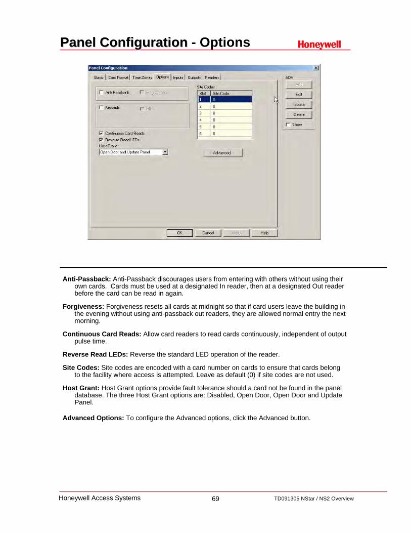
Panel Configuration Panel Configuration - Options
Anti-Passback: Anti-Passback discourages users from entering with others without using their own cards. Cards must be used at a designated In reader, then at a designated Out reader before the card can be read in again.
Forgiveness: Forgiveness resets all cards at midnight so that if card users leave the building in the evening without using anti-passback out readers, they are allowed normal entry the next morning.
Continuous Card Reads: Allow card readers to read cards continuously, independent of output pulse time.
Reverse Read LEDs: Reverse the standard LED operation of the reader.
Site Codes: Site codes are encoded with a card number on cards to ensure that cards belong to the facility where access is attempted. Leave as default (0) if site codes are not used.
Host Grant: Host Grant options provide fault tolerance should a card not be found in the panel database. The three Host Grant options are: Disabled, Open Door, Open Door and Update Panel.
Advanced Options: To configure the Advanced options, click the Advanced button.

70 TD091305 NStar / NS2 OverviewHoneywell Access Systems
Panel Configuration Panel Configuration - Inputs
Input devices bring data into the access control system. They can be in the form of a door status switch, an egress motion, hold up alarm, freezer low temp alert, etc.
Default Input PointInput 1 – Door 1 Egress Input 3 – Door 2 EgressInput 2 – Door 1 Status Input 4 – Door 2 Status
Time Zone: To shunt (deactivate) an input point during a particular time zone, select that time zone from the list.
Shunt Time: Enter a value to set the amount of time that the input point is deactivated (shunted) when triggered.
Debounce Time: Enter a value to set the amount of time that an input must be in a changed state before that change is reported.
Supervised: Select this check box to configure the selected input point as supervised
Report Alarms: Should the alarm report? A configuration in which no alarm report may be needed is when an egress device is connected to the input point.
Interlocking: Interlocking is linking the changing state of the input to another device.

71 TD091305 NStar / NS2 OverviewHoneywell Access Systems
Panel Configuration Panel Configuration - Outputs
Output relays can control devices such as door locks, sounders, etc.
Output Point DefaultsOutput Relay 1 – Door 1Output Relay 2 – Door 2
Output Relay 3 – Aux Relay 3Output Relay 4 – Aux Relay 4
Output Relay 5 – Reader 1 LEDOutput Relay 6 – Reader 2 LED
Time Zone: To turn an output point on during a particular time zone, select that time zone from this list.
First Valid Card: First Valid card read at this reader activates a timezone
Pulse Time: Enter a value here (in seconds, minutes or hours) to set the amount of time that the output point is energized when triggered. This can be any value from 0 to 63.
Interlocking: In the case of output points, interlocking is linking the changing state of the output to either an input, another output.
Report On/Off: When On, the change of state of the out put relay is reported as if it were an Alarm. When Off, no changes of state are reported.
Note: If the Output is time zone controlled, the ‘First Valid Read Activates Time Zone’ check box is available to select. When checked the door remains locked, even when it is in time zone control unlock, until the first valid card is used after the beginning of the time zone.

72 TD091305 NStar / NS2 OverviewHoneywell Access Systems
Panel Configuration Panel Configuration - Readers
Readers are used to interrogate and pass card data to the access control panel.
Door: When selected, treats reader as a door; when not selected treats reader as a reader (i.e., no door contacts).
Card and PIN Time Zone: Selects the time period when both card and PIN must be used.
PIN only Time Zone: Selects the time period when PIN only is required and a card can not be used.
Anti-Passback: When selected, the reader can be configured as an In or Out reader and if hard or soft anti-Passback rules shall be applied.
Free Egress Input Shunts Status Input/Shunt Device: When checked, the egress device shunts the door status. A typical application is a door strike and motion or PIR (touchless) egress device. This prevents the door from unlocking when a person may just walk by the egress sensor.
Note: By clicking Direct Point you can change which output is pulsed on a valid card read. You can also change the pulse time. Changes to the pulse time are reflected automatically in the appropriate input or output. Make any desired adjustments in the settings for interlock, pulse/shunt time, debounce or restore factory defaults from this screen. Changes made here are reflected in the Input or Output tabs.

73 TD091305 NStar / NS2 OverviewHoneywell Access Systems
Defining Control AreasDefining Control Areas
The Control Area is a logical tree / grouping of selected devices. Used in alarm, event and autocard lookup views, this tree will provide an
alternate control to the system through the Control Map.
To Define the Control Area:
• From the Configuration menu, Click on Define, then click Control Areas.
• In the Control Area window, right-click the Control Area folder, then select Add Branch. Enter the branch name you want to add (for example Control Panels).
• Right-click the new branch, then click Add Devices.
• Select the type of device you want to add from the drop down list and then select the device or devices you want to Add to the branch.
• Continue this procedure until you have added all the devices you want displayed on your Control Map. Click the close button (X) to close the Control Areas window.
Note: The Control Area is user definable, and helps organize the usability of the system. There is no definitive way to configure it, as each site will differ, create branches that will help best organize the site.
Configuration > Define > Control Area
74 TD091305 NStar / NS2 OverviewHoneywell Access Systems
Defining Access AreasDefining Access Areas
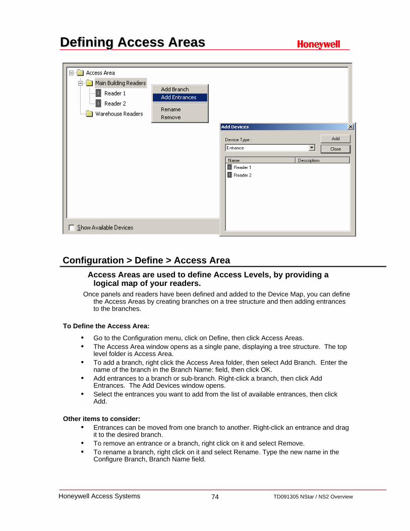
Access Areas are used to define Access Levels, by providing alogical map of your readers.
Once panels and readers have been defined and added to the Device Map, you can define the Access Areas by creating branches on a tree structure and then adding entrances to the branches.
To Define the Access Area:
• Go to the Configuration menu, click on Define, then click Access Areas.• The Access Area window opens as a single pane, displaying a tree structure. The top
level folder is Access Area.• To add a branch, right click the Access Area folder, then select Add Branch. Enter the
name of the branch in the Branch Name: field, then click OK.• Add entrances to a branch or sub-branch. Right-click a branch, then click Add
Entrances. The Add Devices window opens.• Select the entrances you want to add from the list of available entrances, then click
Add.
Other items to consider:• Entrances can be moved from one branch to another. Right-click an entrance and drag
it to the desired branch.• To remove an entrance or a branch, right click on it and select Remove.• To rename a branch, right click on it and select Rename. Type the new name in the
Configure Branch, Branch Name field.
Configuration > Define > Access Area

75 TD091305 NStar / NS2 OverviewHoneywell Access Systems
Configuring Access LevelsConfiguring Access Levels
Access levels determine where and when a user's card is valid in the system. They are defined by selecting entrances and assigning time zones to them.
To Add an Access Level:On the Card menu, click Access Levels. The Access Level window appears.Click the Add button. The secondary Access Level window appears.Enter a name in the Name field and a description in the Description field. Click OK to save the
entry. The new access level is added to the list, but it has no access rights to any entrances. You must now configure the access level.
To Configure an Access Level:Right-click on an Access Area branch, then click Configure. The Configure Area Access dialog
opens. Three options are available:Leave Access for all entrances in this area as it currently is.Remove Access from all entrances in this area.Set Access for all entrances in this area.
To allow access to all doors in the area, select Set Access for all entrance in this area. Then select a time zone from the Time Zone list. Click OK.
A branch can be customized by right clicking on individual entrances.Continue with branches and entrances until the access level has the required configuration.
Other items to consider:• When selecting a branch to Set Access for All Entrances, only the common time zones will be
displayed. If the time zone you are looking to use is not present, it may need to be added to the panel in the panel database.
• Customized access levels can be used to modify cards on an individual basis.• Only 1 access level can be assigned to a card, but a cardholder can have more then 1 card.• Access levels can also be used to define groups of readers in reports.
Card > Access Level

76 TD091305 NStar / NS2 OverviewHoneywell Access Systems
Configure Card Note FieldsConfigure Card Note Fields
Configuration > Card Holder > Note Field TemplateNote Fields are specific fields custom to each site that can be used to store
data, and help refine searches.
To Add Card Holder Note Fields:Select Note Field Template from the Card Holder option on the Configuration menu. The
Note Field Template window appears.The note fields are listed by name, template and tab (if one has been defined).Click Add. The Note Field window appears.In the Name box, enter a unique name for the note field.A blank Template field allows data to be entered in a free form style. Use Mask properties
listed below to define a data template.
Mask properties define Note Field Template(s)While optional, you can define input masks for the Note Fields. The following are examples of standard input masks that you may want to use.
Null String (Default) No mask. Acts like a standard text box.##-???-## Medium date (U.S.). Example: 20-May-92##-##-## Short date (U.S.). Example: 05-20-92##:## ?? Medium time. Example: 05:36 AM##:## Short time. Example: 17:23Drop down list which gives multiple choices. Example: ~brown ~blue ~green
77 TD091305 NStar / NS2 OverviewHoneywell Access Systems
Configure Card Note Field TabsConfigure Card Note Field Tabs
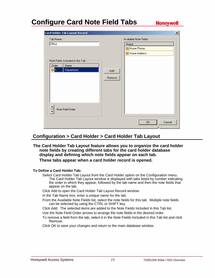
The Card Holder Tab Layout feature allows you to organize the card holder note fields by creating different tabs for the card holder database display and defining which note fields appear on each tab. These tabs appear when a card holder record is opened.
To Define a Card Holder Tab:Select Card Holder Tab Layout from the Card Holder option on the Configuration menu.
The Card Holder Tab Layout window is displayed with tabs listed by number indicating the order in which they appear, followed by the tab name and then the note fields that appear on the tab.
Click Add to open the Card Holder Tab Layout Record window.In the Tab Name box, enter a unique name for the tab.From the Available Note Fields list, select the note fields for this tab. Multiple note fields
can be selected by using the CTRL or SHIFT key.Click Add. The selected items are added to the Note Fields Included in this Tab list.Use the Note Field Order arrows to arrange the note fields in the desired order.To remove a field from the tab, select it in the Note Fields Included in this Tab list and click
Remove.Click OK to save your changes and return to the main database window.
Configuration > Card Holder > Card Holder Tab Layout

78 TD091305 NStar / NS2 OverviewHoneywell Access Systems
Add a CardholderAdd a Cardholder
Card holders are the people to whom cards can be issued to. The Card Holder Database contains card holder information, card numbers and badging photos
on all the card holders that have been entered into the system. Photos can be added to the card holder information either by capturing video images or importing
digital files created in other programs, for example scanned images or photos taken with a digital camera.
To add a Card Holder:Click the card holder button or click Card Holder in the Card menu.The Card Holder database dialog appears.Click Add to activate the record view.On the first tab, enter the card holder's First and Last Name. This is the minimum
information required to add a card holder. If you click OK at this point, the new card holder is added without any cards being attached.
To associate a photo or signature with the badge:In the Card Holder’s record, click the Card Biometrics TabClick Capture or Import from the Card Biometrics tab to open the Capture Image window.
If Importing a photo, navigate to the folder containing your photo files, select the correct file and click Open.
If Capturing a live image, click Freeze, to capture the live image. Once the picture is frozen or captured, adjustments as needed.
Click OK to close Image dialog and the photo appears in the Card Biometrics tab.
Note: System must be upgraded with NSOPT1 for photo badging option to function.
Card > Card Holder

79 TD091305 NStar / NS2 OverviewHoneywell Access Systems
Add a card to the CardholderAdd a card to the Cardholder
Cards are physical credentials that are presented to a reader when access to a door is requested.
A card must have a valid access level in order to unlock a specified door. The Card Holder Database contains all card information via the Cards Tab.
To assign an existing card to a Card Holder:While adding or editing a card holder, click the Cards tab, then click Attach to issue a card which
is already entered in the Card database. If no existing cards are displayed, you must add a new card.
To assign a new card to a Card Holder:Click the Cards tab, and the Card database record view opens. In the Card menu, click Card and the Card window appears. Click Add and enter the Card Number (required).Select an Access Level from the Access Level list (required).By default, a card has an Inactive status as soon as it is entered into the system, and must be
made Active if it is to be used in the system.If you want to select an activation date, click Change from the Activation Date area. If you want the card to be valid for a limited time, click Change from the Expiration Date area. To associate a badge layout with the card, click the Badge tab. Select a Badge Front and Badge
Back Use the Custom Access Level option to set a custom [usually limited] access level for the card.Action groups can be used to set specific actions to occur when a card is read in different states,
for example when its status is Lost/Stolen or Trace rather than Active.Once the card has been defined, click OK and you will return to the Card Holder database.When you have finished, click OK to save the new card. Or, click Cancel to return to the Card
database window without saving the new card.
Card > Card Holder

80 TD091305 NStar / NS2 OverviewHoneywell Access Systems
Using Search and SortUsing Search and Sort
The Search and Sort fields allow you to search the database and choose the order in which the data appears listed on your screen.
The options are explained below use the Card Holder database as an example:
Search Field: Search for card holders by first name, last name, or any note field, or display all of the card holders by selecting .ALL.
Criteria: Choose to search for card holders based on the Search Field beginning with, being equal to, greater than, or less than what you enter in the Criteria field.
Search For: Search by letters.
Sort By: Sort the card holders in the list by either first name, last name or any note field.
Update List: Click to begin the search or sort.
To Search for a Card Holder:From the Search Field list, select the first name, last name or the note field you want to find.Choose the criteria you want to use: Begins with, Greater than, Less than.In the String to Search field, enter the beginning letters for the names you are seeking.Click Update List. A list of cards meeting the criteria is displayed.
NOTE: The number of records returned from the result of your search is restricted by the value set in your Workstation Defaults, Defaults tab: Maximum Records returned from the Database Find List.

81 TD091305 NStar / NS2 OverviewHoneywell Access Systems
Configure / Add Operator LevelConfigure / Add Operator Level
In the Operator Level database, add operator rights (to view, to operate, none), to devices in the control tree, databases and user interfaces.
Each device, database, and user interface is color-coded in the tree per the assigned right:Red: No rights. Yellow: View rights. Green: Operate rights (view and edit). White: Delete rights (database only).
Right-click on a sub-branch to configure it for an operator level. Same: All rights stay as they are.None: Operators will have no rights within this sub-branch.View: Operators will be able to view all the data within this sub-branch.Operate: Operators will be able to view and edit all the data within this sub-branch.Add: Add or edit databaseDelete: Maximum Database rights.
Below the left pane of the Operator Level database are five buttons:Add: Click this button to define a new operator level.Edit: Click this button to make changes in an existing operator level.Copy: To save time when creating similar operator levels, use the Copy button to duplicate
an operator level, then make any desired changes.Delete: Click this button to remove the selected operator level.Isolate: Click this button to view all the operators assigned to the selected operator level
and/or to reassign any (or all) such operators to a different operator level.
System > Operator Level

82 TD091305 NStar / NS2 OverviewHoneywell Access Systems
Configure / Add OperatorConfigure / Add Operator
The Operator Database contains information on all NStar operators. Operators can view and/or change various parts of the NStar system, based on their operator level and the rights assigned to that level. The Operator Level is defined in the Operator Level database.
Operator Tab:Operator Type: Click on the pull-down arrow and select one of the following:Operator: Needs to be assigned an operator level.Admin: Has global rights may view and edit any and every part of the system. Does not
need to be assigned an operator level.Operator Name: Type in a name (up to 30 alphanumeric characters) for this operator.Description: Type in a description (up to 60 alphanumeric characters) for this operator.
Operator Information Tab:Operator Level: Select the Operator Level for this operator. This option is grayed out if
Admin is selected on the Operator tab.Card Holder: Select the operator's card holder name. (optional field)Time Zone: Select the time zone when the operator level is valid. For example, if an
operator's time zone is 8:00 AM until 5:00 PM, Monday through Friday, then the rights within his/her time zone will be activated from 8 to 5, Monday through Friday. An operator cannot log-in to the system earlier than the beginning of the assigned timezone. If an operator is not assigned a time zone, the operator has no time restrictions on his/her log-in rights. If the operator works beyond the assigned time zone, the operator may continue until he or she logs out ( this allows the operator to continue to work during a crisis situation.)
Language: Select the language for the user interface to be used by this operator.
System > Operator
83 TD091305 NStar / NS2 OverviewHoneywell Access Systems
Control MapControl Map
The Control Map provides a means of controlling devices and acknowledging and clearing alarms.
To Control Devices from the Control Map: Right-click on any device to access its control menu, and then click on the desired command.
Control Map Status SymbolsOne of three status symbols may appear before an ADV icon on the Control Map screen.Red square = alarmGreen circle = normalYellow triangle = troublePurple question = unknown
Note: The status symbols will darken after their respective conditions have been acknowledged and cleared. A forbidden symbol overlaid over a status symbol indicates that the corresponding point is shunted. Placing the mouse over the status symbols will bring up a description of the status for each device.
Operations> Control Map

84 TD091305 NStar / NS2 OverviewHoneywell Access Systems
Control Map Control Map -- Initialization
Programming information entered into the NStar system must be sent to the panels before it can take effect.
When panels are first added to the system, they must be initialized so that the information entered into the computers database during panel configuration can be sent to the panels.
To initialize panels (download changes): Right click on the panel icon and select initialize.
Panel Initialization Options:Panel Configuration Options: Sends all panel configuration information. This resets your panel
programming. It is recommended that the Select All feature is selected when this option is chosen.
Time & Date: Updates the panel time and date with the network time and date. You may notice a pause for up to 50 seconds when the time and date are sent .
Cards: Sends card information to the panel. When sending cards it is recommended that you re-initialize the panel by choosing Select All. This ensures that old card information is removed when the new card information is added.
Holidays: Updates holiday information in panel.Time Zones: Updates Time Zone information in panel.Inputs: Updates Input information in panel.Outputs: Updates Output information in panel.
Note: Panel Configuration Options reset all of your panel’s programming. It is recommended that you select all options (check the Select All check box) when sending the Panel Configuration Options.
When cards with an Active or Trace status are added, edited, or deleted from the card or card holder database, this information is automatically sent to the panels. All other card information changes must be sent using this command.
Initialization of panels needs to be done any time changes to any database other then cards or access levels is made.
Operations> Control Map> Initialization

85 TD091305 NStar / NS2 OverviewHoneywell Access Systems
ReportsReports
NStar allows you to generate a variety of reports that can be viewed on screen or printed.
To Generate a Report:Click the Run Reports toolbar button or select the Reports option in the main menu. Some reports have a variety of filters and sort options. After selecting the options you want, click
Print Preview to view the report before printing.Note: (A default printer must be added to the host computer prior to running reports.)
Print Preview: Click to preview the report.Print: Click to print the report.Export File: Click to produce a delimited txt file output.Estim. Pages: Click to get an approximate page count for the report.
Available Reports:
Reports
•Note Field Template•Card Holder Tab Layout
•Time Zone•Holiday Groups•Card Holders
•Schedule•History•Card
•Operator Level•Device Map•Card History
•Operator Actions•Control Area•Access Level
•Operator•Card•Access Area

86 TD091305 NStar / NS2 OverviewHoneywell Access Systems
DATABASEDATABASEMAINTENANCEMAINTENANCE

87 TD091305 NStar / NS2 OverviewHoneywell Access Systems
Purging Data from the DatabasePurging Data from the Database
Database maintenance provides tools for removing unused information from the databases.
When records are deleted from a database, they are no longer available, but they have not actually been removed from the hard disk.
Use the Remove Deleted Records utility to remove them, thus reducing the size of your database.
To Remove Deleted Database Records:Select Remove Deleted Records.Click Start. A box appears reminding you to make a back-up copy before deleting records.
Click No to stop the deletion process or click Yes to proceed.Unwanted history files can also be removed from the databases. This is generally done
after you make a backup copy of your database files. Use the Delete History utility to delete history records before a selected date.
NOTE: Deleted records should be removed monthly, after making a backup copy of the database. These records are no longer available for reports unless the report is run from Archive Database.
To Delete History from the Databases:Select Delete History.Click the Change button, and either click Today or select a date for the Until Date field. All
history entered prior to the selected date will be removed from the databases.Click Start
NOTE: Removal of the deleted database records and removal of unwanted history can be done separately or at the same time. The date selection only applies to history records.
File > Database Maintenance

88 TD091305 NStar / NS2 OverviewHoneywell Access Systems
Database Limits & CapacitiesDatabase Limits & Capacities
Database Limits and Capacities monitors the available space for the database (system programming and history - excludes photo and badging images) and available hard drive space.
• The Database section provides current database size information listed as Current Size and displays the percentage of the database that is used. The MSDE database engine allows for a maximum size of 2GB (excluding photo and badging images). The Warning and Alarm thresholds are defined in MB (megabytes), in addition percentages are displayed.
• The Database Disk Drive Free Space section reports Current Free Space of the hard drive where the database is located. In installations where the database is located on a separate drive, it is recommend that at least 2.5 times the maximum size of the database be left as free space. If the database is installed on the same drive as the OS, then 1/3 free space of the hard drive should be used. This allows enough room for backups and archive actions to occur.
File > Database Limits and Capacities

89 TD091305 NStar / NS2 OverviewHoneywell Access Systems
Backup & Restore UtilityBackup & Restore Utility
The NStar Backup and Restore utility is a stand-alone application that allows the user-typically a database administrator-to create and modify a backup and restore plan.
Database copies made with the Backup and Restore utility can be used to restore-or recreate-your database after a failure has occurred.
90 TD091305 NStar / NS2 OverviewHoneywell Access Systems
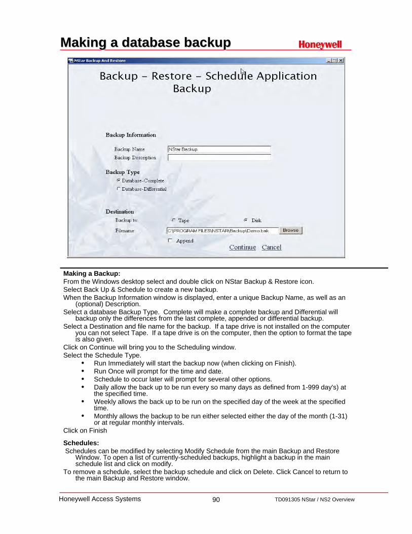
Making a database backupMaking a database backup
Making a Backup:From the Windows desktop select and double click on NStar Backup & Restore icon.Select Back Up & Schedule to create a new backup.When the Backup Information window is displayed, enter a unique Backup Name, as well as an
(optional) Description.Select a database Backup Type. Complete will make a complete backup and Differential will
backup only the differences from the last complete, appended or differential backup.Select a Destination and file name for the backup. If a tape drive is not installed on the computer
you can not select Tape. If a tape drive is on the computer, then the option to format the tape is also given.
Click on Continue will bring you to the Scheduling window.Select the Schedule Type.
• Run Immediately will start the backup now (when clicking on Finish).• Run Once will prompt for the time and date.• Schedule to occur later will prompt for several other options.• Daily allow the back up to be run every so many days as defined from 1-999 day's) at
the specified time.• Weekly allows the back up to be run on the specified day of the week at the specified
time.• Monthly allows the backup to be run either selected either the day of the month (1-31)
or at regular monthly intervals.Click on Finish
Schedules:Schedules can be modified by selecting Modify Schedule from the main Backup and Restore
Window. To open a list of currently-scheduled backups, highlight a backup in the main schedule list and click on modify.
To remove a schedule, select the backup schedule and click on Delete. Click Cancel to return to the main Backup and Restore window.

91 TD091305 NStar / NS2 OverviewHoneywell Access Systems
Making a database backupMaking a database backup
IMPORTANTThe Backup and Restore utility will only backup the NStar hardware and history database information.
Other data, such as badge images and signatures and badge graphics are not backed up by this utility. This data is normally found in the NStar\DATABASE folder with Badge Image and User Image subfolders.
During the NStar installation, prompts are provided to allow the installer to place these subfolders at other locations in your system therefore; you may not find these subfolders in the NStar folder.
Backup of these data folders can be accomplished using standard Windows backup or copying utilities.
Both should be done at the same time to keep all information current.
Badge Artwork
Badge Photos
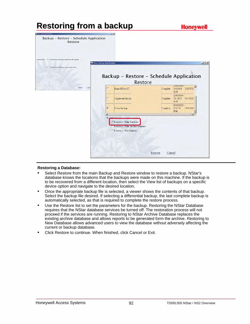
92 TD091305 NStar / NS2 OverviewHoneywell Access Systems
Restoring from a backupRestoring from a backup
Restoring a Database:• Select Restore from the main Backup and Restore window to restore a backup. NStar's
database knows the locations that the backups were made on this machine. If the backup is to be recovered from a different location, then select the View list of backups on a specific device option and navigate to the desired location.
• Once the appropriate backup file is selected, a viewer shows the contents of that backup. Select the backup file desired. If selecting a differential backup, the last complete backup is automatically selected, as that is required to complete the restore process.
• Use the Restore list to set the parameters for the backup. Restoring the NStar Database requires that the NStar database services be turned off. The restoration process will not proceed if the services are running. Restoring to NStar Archive Database replaces the existing archive database and allows reports to be generated form the archive. Restoring to New Database allows advanced users to view the database without adversely affecting the current or backup database.
• Click Restore to continue. When finished, click Cancel or Exit.

93 TD091305 NStar / NS2 OverviewHoneywell Access Systems
Restoring an ArchiveRestoring an Archive
The Archive database is created by restoring a database that has been backed up to the Archive database.
Once restored, a report can be generated by checking the "Run from Archive Database" box in the report window.
94 TD091305 NStar / NS2 OverviewHoneywell Access Systems
NSOPT1 SOFTWARE UPGRADENSOPT1 SOFTWARE UPGRADE

95 TD091305 NStar / NS2 OverviewHoneywell Access Systems
NSOPT1 Software Upgrade NSOPT1 Software Upgrade
NStar offers an upgrade option package for users with greater needs. The package offers the ability to add Photo-ID Badging, Alarm/Event
Monitoring, Digital Video Integration and the ability to network multiple PC’s together.
This option package can be activated immediately upon registration of software.
The following optional features are available with the NSOPT1 software upgrade:
• Networking – up to five concurrent users • Prioritized alarms – 1 to 99 priorities • Alarm messages and operator notes • Integrated digital video (Rapid Eye) with PTZ control • Alarm and video pop-up • System events viewer • Photo ID badging • Magnetic stripe encoding • Duplex printing – two sided badge printing

96 TD091305 NStar / NS2 OverviewHoneywell Access Systems
Client Installation / User Interface TabClient Installation / User Interface Tab
The User Interface tab in the System Manager is used when a client installation is performed on a remote machine
When installing NStar on a workstation that is networked with the NStar Server, on the client PC, select the User Interface Only installation. The User Interface can be installed from the CD ateach workstation or it can be installed across the LAN.
INSTALLATION NOTE: When installing over a LAN, make sure the install directory resides on a drive that is shared and mapped in the target system. If this is not the case, the install will fail when the system reboots and attempts to reestablish the connection to the host directory.
To install the NStar User Interface, exit any Windows programs that are running, and insert the NStar CD into your CD drive. The installation program begins, and runs as described in the "Installation Procedure" section of this chapter.
When prompted, select the User Interface Only installation to install only the User Interface.
After the software installation has been completed, open the NStar System Manager on the desktop to configure connectivity to the NStar Server.
Display Name: Type a descriptive name to identify the database server in the list.
Database Server Node Name: Enter the Node Name or IP address of the remote Database Server machine
Database Archive Server Node Name: Enter the Node Name or IP address of the remote Archive Database Server machine
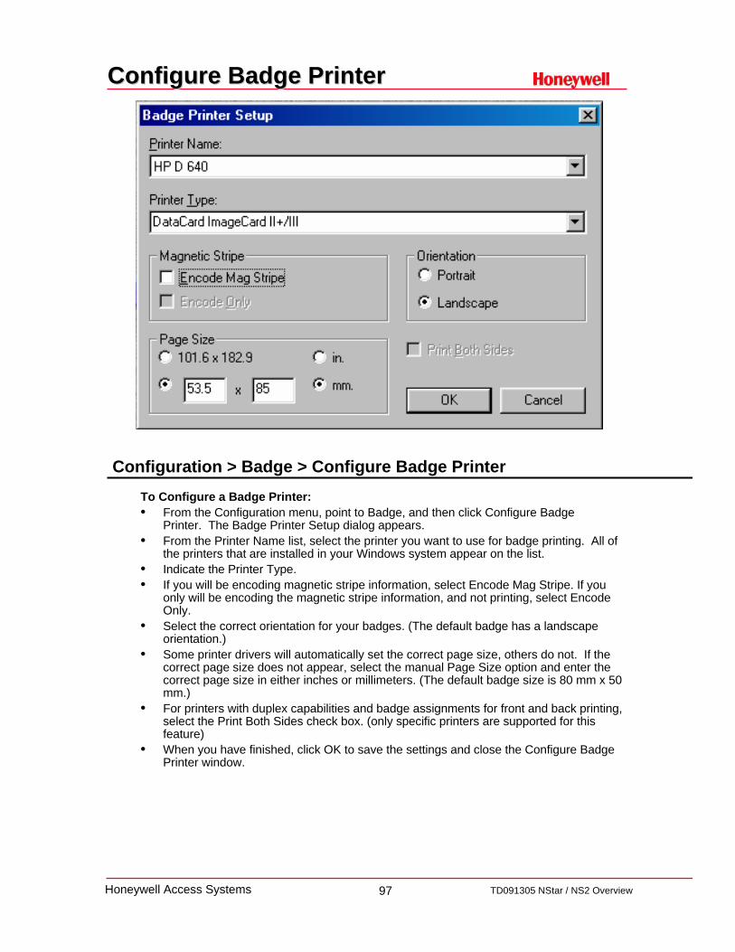
97 TD091305 NStar / NS2 OverviewHoneywell Access Systems
Configure Badge PrinterConfigure Badge Printer
To Configure a Badge Printer:• From the Configuration menu, point to Badge, and then click Configure Badge
Printer. The Badge Printer Setup dialog appears.• From the Printer Name list, select the printer you want to use for badge printing. All of
the printers that are installed in your Windows system appear on the list.• Indicate the Printer Type.• If you will be encoding magnetic stripe information, select Encode Mag Stripe. If you
only will be encoding the magnetic stripe information, and not printing, select Encode Only.
• Select the correct orientation for your badges. (The default badge has a landscape orientation.)
• Some printer drivers will automatically set the correct page size, others do not. If the correct page size does not appear, select the manual Page Size option and enter the correct page size in either inches or millimeters. (The default badge size is 80 mm x 50 mm.)
• For printers with duplex capabilities and badge assignments for front and back printing, select the Print Both Sides check box. (only specific printers are supported for this feature)
• When you have finished, click OK to save the settings and close the Configure Badge Printer window.
Configuration > Badge > Configure Badge Printer

98 TD091305 NStar / NS2 OverviewHoneywell Access Systems
BadgingBadging-- Badge .DLLBadge .DLL’’ss
A specific dynamic-link library (.DLL) file is required for the video capture card, TWAIN device and signature pad.
The DLLs for currently supported hardware are included in the NStar directory and can be installed from within NStar.
To Install Badge DLL’s:On the Configuration menu, point to Badge, and then click Badge DLLs.The Badge DLLs dialog has fields for Video Capture Card DLL, and Signature Pad DLL.
Click the ellipsis button next to the hardware device you have installed.A window opens to the NStar directory. Select the appropriate DLL file and click Open.
The DLL name is entered in the box below the hardware device in the Badge DLL window.
Click OK to save your selections and close the Badge DLL window.
Note: Windows explorer settings should be set to view all file types, otherwise the DLL files may be hidden by the OS.
Typical DLLs: Flashbus.dll - Used in conjunction with the PBVC15 - Flashbus cardTWAIN.DLL - Used with devices that have a TWAIN interface such as a scannerPenWare.dll - Used with the PBSIGCAPLCD (signature capture pad).
Configuration > Badge > Badge .DLL’s

99 TD091305 NStar / NS2 OverviewHoneywell Access Systems
Badging: Badge LayoutBadging: Badge Layout
Badge layouts or designs are templates that define the size, placement and other properties of a badge.
To Create a Badge Layout:Click Add from the Badge Layouts window to activate the Badge Definition window.Enter a name for the badge layout If the default badge size needs to be changed, right-click anywhere in the Badge Layout
window, select Properties, then click the Positioning tab.Click Apply to apply the change to your badge.Click OK to apply the change and return to the Badge Layouts window.
To change this size, right-click anywhere in the Badge Layout window, select Properties, then click the Positioning tab.
Click Apply to apply the change to your badge. Click OK to apply the change and return to the Badge Layouts window.
To Add an Item to the Badge:Six types of items can be placed on a badge: text, bitmap, photo, barcode, shape, and
signature.Click the button on the toolbar that corresponds to the item that you want to add.Right click on the object and select properties to set object sensitive information.
Configuration > Badge > Badge Layout Utility

100
TD091305 NStar / NS2 OverviewHoneywell Access Systems
Auto Card LookupAuto Card Lookup
The Autocard Lookup responds to a card read by displaying the card holder name, reader name, status of the card read event and time and date in an on-screen pop up window.
If there is a photo of the card holder in the database, it is also displayed in the Autocard Lookup window as well.
To Configure Autocard Lookup:On the Configuration menu, point to Card Holder, then click Configure Autocard Lookup.
The Autocard Lookup Configuration dialog appears.From the Show Note Fields: list, select the note fields you want included in the Autocard
Lookup report. The note field names are selected by left clicking on the note field name and unselected by left clicking on that name again.
When you have finished click OK to save your changes or click Cancel to close the window without making any changes.
Other items to consider:Using the Configure Autocard Lookup utility to select which note fields are displayed, you
can include additional information in this view. Based on the operator access permissions, some fields may not be visible.
Operations > Autocard LookupConfiguration > Card Holder > Configure Autocard Lookup

101
TD091305 NStar / NS2 OverviewHoneywell Access Systems
Rapid Eye IntegrationRapid Eye Integration
Configuration > Device > Device Map > Digital Video
Digital Video ConfigurationName: Enter the name of the Digital Video Recorder. This must be identical to the Rapid Eye Digital
Recorder name.Description: OptionalUser: The User Name must be identical to the User Name defined in the Rapid Eye Digital Recorder.Password: The password must be identical to the password defined in the Rapid Eye unit software.ADV: Click “Add” then press Enter on the keyboard
NOTE: When using the Rapid Eye Digital Recorder, the View software must be installed for video to be viewed from within NStar.
Camera ConfigurationFor each camera to be used in the system, click on the check box, then double click on the ADV to
the right of it and type the camera name. Additionally, all new cameras must be added to the Control Map before you can view live video.
Pan and Tilt: Define a camera as a PTZ (pan tilt zoom) Camera. (De-selecting the Pan and Tiltoption defines the camera as a stationary camera.)
Camera Title: The title of the camera
NOTE: The sequential order of the ADVs corresponds to the sequential order of the Rapid Eye Digital Recorder cameras.
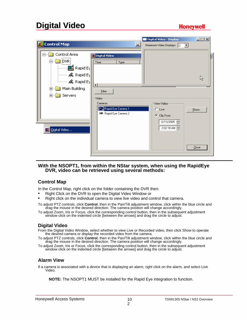
102
TD091305 NStar / NS2 OverviewHoneywell Access Systems
Digital VideoDigital Video
With the NSOPT1, from within the NStar system, when using the RapidEye DVR, video can be retrieved using several methods:
Control MapIn the Control Map, right click on the folder containing the DVR then:• Right Click on the DVR to open the Digital Video Window or• Right click on the individual camera to view live video and control that camera.To adjust PTZ controls, click Control, then in the Pan/Tilt adjustment window, click within the blue circle and
drag the mouse in the desired direction. The camera position will change accordingly. To adjust Zoom, Iris or Focus, click the corresponding control button, then in the subsequent adjustment
window click on the indented circle [between the arrows] and drag the circle to adjust.
Digital VideoFrom the Digital Video Window, select whether to view Live or Recorded video, then click Show to operate
the desired camera or display the recorded video from the camera.To adjust PTZ controls, click Control, then in the Pan/Tilt adjustment window, click within the blue circle and
drag the mouse in the desired direction. The camera position will change accordingly. To adjust Zoom, Iris or Focus, click the corresponding control button, then in the subsequent adjustment
window click on the indented circle [between the arrows] and drag the circle to adjust.
Alarm ViewIf a camera is associated with a device that is displaying an alarm, right click on the alarm, and select Live
Video.
NOTE: The NSOPT1 MUST be installed for the Rapid Eye integration to function.