NSG 4070C-LFCP SYSTEM FOR MAGNETC FIELD TESTNG IN THE ...
14
SYSTEM FOR MAGNETIC FIELD TESTING IN THE CLOSE PROXIMITY NSG 4070C-LFCP The NSG 4070C-LFCP is a universal device for standard-compliant and development-accompanying EMC immunity tests in the application area of magnetic field testing in the close proximity according to IEC / EN 61000-4-39 and IEC / EN 60601-1-2. The NSG 4070C-LFCP integrates signal generator, directional coupler, power amplifier, power meter and EUT monitoring interfaces. The NSG 4070C-LFCP can be operated quickly, conveniently and easily via the front panel as a free-standing device. Test and measurement data can be conveniently transferred for documentation purposes via a USB stick. The NSG 4070C-LFCP can be remote controlled via LAN, electrical or optical RS232 as well as USB. The wide frequency range of the signal generator and the power meter offer the possibility to connect external amplifiers and directional couplers. In combination with a remote control software, external power amplifiers and directional couplers, further applications can be covered, such as testing of con- ducted disturbances induced by high frequency fields according to IEC / EN 61000-4-6, automotive BCI tests e.g. according to ISO 11452-4 as well as high frequency electromagnetic fields according to IEC / EN 61000-4-3 or IEC / EN 61000-4-20. For EUT monitoring, the NSG 4070C-LFCP offers a variety of interfaces for flexibility in laboratory use. In order to start with predefined parameter settings the optional test software icd.control is recom- mended. The software offers a large standard database and predefined drives for using external mea- suring devices. More complex systems including radiated tests can be controlled by using the software solution CIS (Compliance Immunity Software). Integrated signal generator 4 kHz to 1 GHz 3 power meter inputs 4 kHz to 1 GHz Integrated class A power amplifier 100 W, 9 kHz to 50 MHz Multiple EUT monitoring options 5.7“ TFT color display Internal, menu-based control software Whisper mode Standards: IEC / EN 61000-4-39 IEC / EN 60601-1-2 Generator Power Amplifier AMP OUT CH. 1 4x TTL input 4x TTL output CH. 2 CH. 3 RF OUT AMP IN* BRIDGE POWER METER INPUT USER PORT ANALOG PORT Forward Power ƒ Directional Coupler DIGITAL PORT OPTICAL PORT EXTERNAL MODULATION TRIGGER Reverse Power Forward Power Target Level EUT Monitoring Interface Block diagram of NSG 4070C-LFCP
Transcript of NSG 4070C-LFCP SYSTEM FOR MAGNETC FIELD TESTNG IN THE ...

SYSTEM FOR MAGNETIC FIELD TESTING IN THE CLOSE PROXIMITY
NSG 4070C-LFCP
The NSG 4070C-LFCP is a universal device for standard-compliant and development-accompanying EMC immunity tests in the application area of magnetic field testing in the close proximity according to IEC / EN 61000-4-39 and IEC / EN 60601-1-2. The NSG 4070C-LFCP integrates signal generator, directional coupler, power amplifier, power meter and EUT monitoring interfaces. The NSG 4070C-LFCP can be operated quickly, conveniently and easily via the front panel as a free-standing device. Test and measurement data can be conveniently transferred for documentation purposes via a USB stick. The NSG 4070C-LFCP can be remote controlled via LAN, electrical or optical RS232 as well as USB.
The wide frequency range of the signal generator and the power meter offer the possibility to connect external amplifiers and directional couplers. In combination with a remote control software, external power amplifiers and directional couplers, further applications can be covered, such as testing of con-ducted disturbances induced by high frequency fields according to IEC / EN 61000-4-6, automotive BCI tests e.g. according to ISO 11452-4 as well as high frequency electromagnetic fields according to IEC / EN 61000-4-3 or IEC / EN 61000-4-20. For EUT monitoring, the NSG 4070C-LFCP offers a variety of interfaces for flexibility in laboratory use.
In order to start with predefined parameter settings the optional test software icd.control is recom-mended. The software offers a large standard database and predefined drives for using external mea-suring devices. More complex systems including radiated tests can be controlled by using the software solution CIS (Compliance Immunity Software).
Integrated signal generator
4 kHz to 1 GHz
3 power meter inputs
4 kHz to 1 GHz
Integrated class A power amplifier
100 W, 9 kHz to 50 MHz
Multiple EUT monitoring options
5.7“ TFT color display
Internal, menu-based control
software
Whisper mode
Standards:
IEC / EN 61000-4-39
IEC / EN 60601-1-2
Generator Power Amplifier
AMP OUT CH. 1
4x TTL input4x TTL output
CH. 2 CH. 3RF OUT AMP IN*
BRIDGE POWER METER INPUT
USER PORTANALOG PORT
Forward Power
ƒ
Directional Coupler
DIGITALPORT
OPTICALPORT
EXTERNALMODULATION
TRIGGER
ReversePower
ForwardPower
TargetLevel
EUT Monitoring Interface
Block diagram of NSG 4070C-LFCP

SYSTEM FOR MAGNETIC FIELD TESTING IN THE CLOSE PROXIMITY
NSG 4070C-LFCP
Generatorƒ
Power Amplifier
Directional Coupler
CH. 3
CH. 2
CH. 1
Reverse Power
Current,Forward Power
Target Level,Receiving Antenna
4x TTL input4x TTL output
USER PORTANALOG PORT
DIGITALPORT
OPTICALPORT
EUT Monitoring Interface
Modules of NSG 4070C-LFCP
The heart of the device is the signal generator, which gener-ates the sinusoidal signal over the wide frequency range from 4 kHz to 1 GHz and in the level range -60 dBm to +10 dBm. The built-in modulator allows amplitude and pulse modulation. The NSG 4070C-LFCP contains extended parameters for pulse modulation and allows up to three envelopes to be inter-leaved. One input allows modulation from an external source.
The output of the signal generator is connected to the internal power amplifier via a bridge. Next to the amplifier a directional coupler is connected to measure the forward power.
The NSG 4070C-LFCP can measure forward and reverse power via an external directional coupler. For this application, power meter inputs 2 and 3 are located on the front panel. The power meter input 1 is intended for adjusting the target value. The power meter input 2 of NSG 4070C-LFCP is intended for connecting the current probe in the range 9 kHz to 150 kHz.
The EUT monitoring interface allows the simple and fast inte-gration of the interfaces of the EUT to be monitored. The TTL inputs and outputs of the NSG 4070C-LFCP can be used to integrate additional equipment for monitoring test specimens. The optical EUT monitoring input can detect the status of an indicator lamp. When using the extensive EUT monitoring functions, the user receives a meaningful test result with assignment of the events to the respective test frequency. Subsequent design changes to the EUT can thus be qualified more quickly.

SYSTEM FOR MAGNETIC FIELD TESTING IN THE CLOSE PROXIMITY
NSG 4070C-LFCP
User port for 4 TTL inputs and 4 TTL outputs and supply voltages for individual monitoring and control applications
Analog, digital and optical monitoring inputs for extensive EUT monitoring options
2x USB, 10 MHz refer-ence output, Trigger input, external modula-tion input
Remote control viaoptical RS232, RS232, LAN or USB
Back panel
External access to signal generator output and power amplifierinput and output
3 power meter inputs
5.7“ color display,easy to use firmware
Hard keys forimportant functions
Front panel
SYSTEM FOR MAGNETIC FIELD TESTING IN THE CLOSE PROXIMITY
NSG 4070C-LFCP
Configuration Calibration Testing
During the EMC tests, the test object undergoes different tests at different test stations. Among other things, short set-up times are an advantage so that the operating personnel can efficiently test the EUT. Switching on and testing expresses the wish of many users. With its unique menu-driven operation, the NSG 4070C-LFCP fulfils this wish to operate magnetic field testing according to IEC / EN 61000-4-39 and IEC / EN 60601-1-2 from the front panel of the device. On-site testing of machines and systems is possible with the NSG 4070C-LFCP. The NSG 4070C-LFCP contains configurations that the operator can load or modify according to the test being performed. This allows the parameter setting to be carried out with a user activity and in the shortest possible time. To execute a test, an existing system calibra-tion file would have to be loaded or generated. Thanks to the very fast power meters and firmware optimized for fast measurement, the NSG 4070C-LFCP takes less than a minute to calibrate for IEC / EN 61000-4-39 the range 9 kHz to 150 KHz or 150 kHz to 26 MHz. During the test, the display changes to show the current frequency, level, EUT monitoring channels and their states. The response to EUT monitoring events can be adjusted. Irrespective of the EUT monitoring, the sweep can be interrupted with the “HOLD” key to manually change the frequency and level, for example, to further investigate the reaction of the DUT. Test results can be saved and reloaded as required. Based on a loaded test, tests can be repeated easily as the test configuration and system calibration data are included. When the test result is saved on a USB stick, a simple test report in PDF format and CSV format is also saved.
In addition to the Immunity menu for performing the EMC test, the NSG 4070C-LFCP, with two further menus, offers the option of operating the device as a stand-alone signal generator. The measured values of the power meters are displayed in the power meter menu. The operator can easily check his system and measure cables and attenuators.
Firmware: Immunity mode
Firmware: Generator and Power Meter mode

SYSTEM FOR MAGNETIC FIELD TESTING IN THE CLOSE PROXIMITY
NSG 4070C-LFCP
Technical specifications
Generator
RF Frequency range: 4 kHz to 1 GHz Resolution: 1 Hz Reference frequency: 10 MHz Aging: 25 ppm RF Level Level range: -60 dBm to +10 dBm Resolution: 0.1 dB Settling time: 10 msAmplitude modulation Modulation depth: 0 to 100% Modulation frequency range: 1 Hz to 50 kHz Frequency resolution: 1 HzPulse modulation (possible to interlace up to three pulse modulations) Rise / fall time (10% / 90%): < 1 µs Modulation frequency range: 0.01 Hz to 1 MHz Frequency resolution: 0.01 Hz Duty cycle: 0.1% to 100%External modulation Delay time: < 1 µs / 180° Period: min. 20 µs Pulse width: min. 10 µs
Power meter
Frequency range: 4 kHz to 1 GHzLinear measurement range channel 1: -35 dBm to +27 dBm channel 2,3: -45 dBm to +20 dBm Max. input / no damage channel 1-3: +28 dBm Noise level: >5 dB below the measurement range Input return loss: >20 dB (below 500 MHz), >17 dB (500 MHz to 1 GHz)Connector: BNC socket, 50 ΩAccuracy 10 to 30°C: <0.5 dB, typ. <0.3 dB

SYSTEM FOR MAGNETIC FIELD TESTING IN THE CLOSE PROXIMITY
NSG 4070C-LFCP
Po
we
r in
Wat
ts
140
130
150
160
120
110
100
90
80
70
60
0.01
Frequency in MHz
0.1 1 10 30 100
60.0
70.0
80.0
90.0
100.0
110.0
120.0
130.0
140.0
150.0
160.0
0.001 0.01 0.1 1 10 100
Pow
er in
Wa
s
freq [MHz]
P1dB Power in Was Psat Power in Was
Nominal output power: 100 WFrequency range: 9 kHz - 50 MHzType: single band, class AInput / output impedance (nominal): 50 ΩInput return loss (minimum): 10 dBOutput return loss (nominal): min. 9.5 dBOutput return loss without damage: 0 dBGain (minimum): 50 dBGain flatness (maximum): + / - 3 dBLinear output power (minimum) 9 kHz to 30 MHz: 50 dBm (100 W) 30 MHz to 50 MHz: 49.5 dBm (90 W)Input power without damage (maximum): 0 dBmHarmonic distortion at linear output power (typical): < -20 dBc
Power amplifier
Legend: typical saturated power, typical linear power, specification linear power
Power amplifier of NSG 4070C-LFCP connected to 50 Ohms

SYSTEM FOR MAGNETIC FIELD TESTING IN THE CLOSE PROXIMITY
NSG 4070C-LFCP
0
10
20
30
40
50
60
0.009 0.01 0.02 0.03 0.04 0.05 0.06 0.07 0.08 0.09 0.1 0.11 0.12 0.13 0.14 0.15
Pow
er in
dBm
Frequency in MHz
Power requirements for NSG 4070-LFCP
Forward power in dBm @ 1 A/m Forward power in dBm + AM @ 1 A/m
Forward power in dBm @ 3 A/m Forward power in dBm + AM @ 3 A/m
Forward power in dBm @ 10 A/m Forward power in dBm + AM @ 10 A/m
Forward power in dBm @ 30 A/m
Forward power in dBm @ 30 A/m
Forward power in dBm + AM @ 30 A/m
Max fw. power in dBm, RLA 6120-20 connected* Max forward power in dBm on 50 Ohm terminaon
Forward power in dBm @ 8 A/m Forward power in dBm @ 65 A/m
Example for typical power requirements using LAS 6120
Example for typical power requirements using LAS 6100
-10
0
10
20
30
40
50
60
0.1 0.2 0.3 0.4 0.5 0.6 0.7 0.8 0.9 1 2 3 4 5 6 7 8 9 10 11 12 13 14 15 16 17 18 19 20 21 22 23 24 25 26
Pow
er in
dBm
Frequency in MHz
Power requirements for NSG 4070-LFCP
Forward power in dBm @ 0.1 A/m Forward power in dBm @ 0.3 A/m
Forward power in dBm @ 1 A/m Forward power in dBm @ 3 A/m
Max forward power in dBm, RLA 6100-3 connected* Max forward power in dBm on 50 Ohm terminaon
Forward power in dBm @ 7.5 A/m with ANP 4039

SYSTEM FOR MAGNETIC FIELD TESTING IN THE CLOSE PROXIMITY
NSG 4070C-LFCP
Test and measurement routines
Generator mode
Power meter mode
Immunity mode
Sweep: frequency sweep, level sweepModulation: AM, AM PC (peak conservation), pulse modulation and externalOthers: free parameter setting from 4 kHz to 1 GHz, high power mode using power amplifier
Level setting: free generator level setting via numeric input or rotary knob, generator ON / OFF, power amplifier (internal) ON / OFFFrequency setting: free frequency setting via numeric input or rotary knobPower display: channel 1 to 3, amplifier output (internal)
Level: Start and stop level or sections, levels in A/mLoops: LAS 6120 range 9 kHz to 150 kHz and LAS 6100 range 150 kHz to 26 MHzTest methods: according IEC 61000-4-39 range 9 kHz to 150 kHz and 150 kHz to 26 MHzSweep: Frequency or section sweep with linear, steps per decade or percental increaseModulation: AM, AM PC (peak conservation), pulse modulation, external or mixed (e.g. 1 kHz AM internal modulated with 1 Hz PM external) EUT monitoring: Individual port configuration, EUT monitoring setup and check function, EUT monitoring results displayed during test in both results file and test reportCalibration: System calibration and current probe calibration, display, calibration file store and recall function, recall of sensor loop correction filesEUT threshold search: manual search by changing frequency or stress level Store and recall: function for test configurations, calibration results and test results, supports USB sticksComponent check: quick system component check, e.g. cable, attenuator max. 58 dB insertion lossAdditional features: free parameter setting from 4 kHz to 1 GHz, supports external power amplifier, directional coupler and attenuator (on power meter channel 1)

SYSTEM FOR MAGNETIC FIELD TESTING IN THE CLOSE PROXIMITY
NSG 4070C-LFCP
Analog ports
Digital ports
NSG 4070C-LFCP front panel with RF
ports
Front panel Generator output: N socket 50 Ω, 4 kHz to 1 GHzPower amplifier input: N socket 50 Ω, max. 0 dBmPower amplifier output: N socket 50 ΩPower meter channel 1 to 3: as defined in chapter “Power meter“ Back panel Monitoring input analog: BNC socket, 0 to 24 V Ri=15 kΩ, 6 mV resolutionExternal modulation input: BNC socket, impedance >10 kΩ, level: 1 Vpp to get 100% AM, 1 Hz to 50 kHz10 MHz reference output: BNC socket, approx. 1 Vpp / 50 Ω
Front panel USB: USB host connector for USB stick, keyboard, mouse Back panel User port: D-Sub 15 pole 4 TTL inputs 4 TTL outputs +12 V / 800 mA, -12 V / 200 mA, +5 V / 800 mA power supplyMonitoring digital input: BNC socket 0 to 24 V via optical coupler Ri=1.5 kΩ, switching threshold approx. 2 to 3 VMonitoring optical input: LWL (Light wave connector), HP versatile link HFBR0501 series 40 kBd, (avoid scattered light on the back panel)Trigger input: BNC socket, TTL for external triggering, max. frequency 100 Hz, trigger delay <10 msRS232: D-Sub 9 pole, up to 115200 BdRS232 optical: Connector 2 x HFBRx523 socket for 1 mm fiber optic cable with length between 5 m and 30 m with 115200 Bd, for other distances 38400 Bd, max. 50 m2x USB: USB host connector for USB stick, keyboard, mouseUSB device connector: For remote controlNetwork: RJ45, Ethernet 10 / 100 BASE-T

SYSTEM FOR MAGNETIC FIELD TESTING IN THE CLOSE PROXIMITY
NSG 4070C-LFCP
Power supply
General data
Operating temperature range: 0 °C to 40 °CStorage temperature range: -20 °C to 60 °CRelative humidity: 95 % / 30 °C (no moisture condensation) EMC: DIN / EN 61326-1:2006Shock: DIN / EN 60068-2-27Vibration: DIN / EN 60068-2-6Protection class: DIN / EN 61010-1 / IEC 61010-1
Mechanical specifications
Power consumption 100 to 240 VAC 50 / 60 Hzautoranging
Recommended fuse F1 for nominal 110 V
Recommended fuse F1 for nominal 230 V
NSG 4070C-LFCP approx. 512 W 6.3 A (slow) 2.5 A (slow)
Size (W x H x D) : 45 cm (19“) x 15 cm (3HU) x 42.3 cm (with handle bar and foot)Weight: approx. 15 kg (with internal power amplifier)Cardboard box: 80 cm x 61 cm x 34 cm, approx. 8 kg (empty)
SYSTEM FOR MAGNETIC FIELD TESTING IN THE CLOSE PROXIMITY
NSG 4070C-LFCP
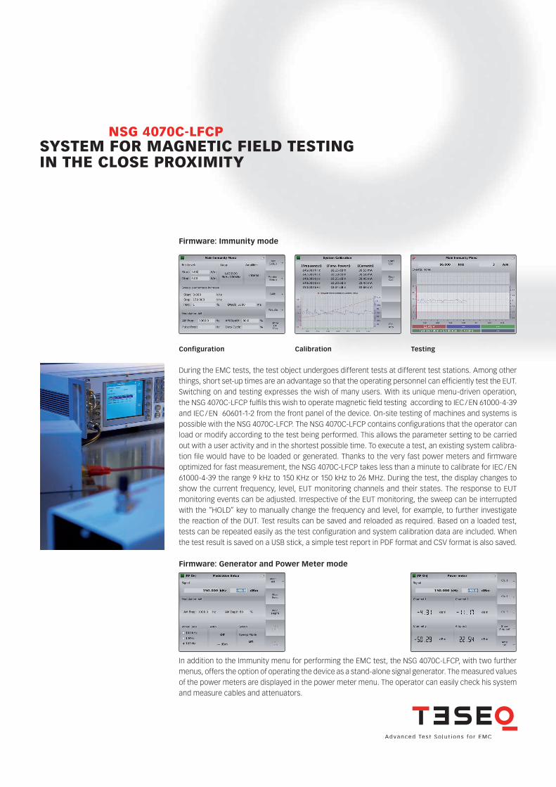
Set up example for test level setting in the frequency range 9 kHz to 150 kHz
Set up example for testing in the frequency range 9 kHz to 150 kHz
RF out
Amp in
< +10 dBm
Amp outch.1 < +27 dBm
ch.2 < +20 dBm
ch.3 < +20 dBmPower meter
NSG 4070
PowerUSB
Tuning
StSizeStSize StSize
Local
Back StopRun
Hold
0 .
1
4
7 8
5
2 3
kHzdBm6
9 MHzdBµV
HzV
Enter
Step1
STO
FRQ LVL
RCL
Step2
Step3
MOD
2nd
Help
RFON/OFF
RLA 6120-20
FSL 6040-51
Compact generator NSG 4070C-LFCP
Power meter
Current sensorCSP 9160A
LE 273
Adaptor N/BNC/Banana
RF out
Amp in
< +10 dBm
Amp out
ch.2 < +20 dBm
ch.3 < +20 dBmPower meter
NSG 4070
PowerUSB
Tuning
StSizeStSize StSize
Local
Back StopRun
Hold
0 .
1
4
7 8
5
2 3
kHzdBm6
9 MHzdBµV
HzV
Enter
Step1
STO
FRQ LVL
RCL
Step2
Step3
MOD
2nd
Help
RFON/OFF
ch.1 < +27 dBm
50 ±3
100 ±5
100 ±5
EUT
100 ±5100 ±5
RLA 6120-20
Compact generator NSG 4070C-LFCP
Power meter
Radiation area panel (100 x 100 mm plate)Dimensions in mm
Current sensorCSP 9160A
LE 273
Adaptor N/BNC/Banana

SYSTEM FOR MAGNETIC FIELD TESTING IN THE CLOSE PROXIMITY
NSG 4070C-LFCP
Set up example for test level setting for the frequency range 150 kHz to 26 MHz
Set up example for test level setting at 13.56 MHz for e.g. 7.5 A/m (IEC 60601-1-2)
RLA 6100-3
FSL 6040-1
CHA 9580
RF out
Amp in
< +10 dBm
Amp outch.1 < +27 dBm
ch.2 < +20 dBm
ch.3 < +20 dBmPower meter
NSG 4070
PowerUSB
Tuning
StSizeStSize StSize
Local
Back StopRun
Hold
0 .
1
4
7 8
5
2 3
kHzdBm6
9 MHzdBµV
HzV
Enter
Step1
STO
FRQ LVL
RCL
Step2
Step3
MOD
2nd
Help
RFON/OFF
Compact generator NSG 4070C-LFCP
Power meter
Matching networkANP 4039
RLA 6100-3
FSL 6040-1 LE 271
CHA 9580
RF out
Amp in
< +10 dBm
Amp outch.1 < +27 dBm
ch.2 < +20 dBm
ch.3 < +20 dBmPower meter
NSG 4070
PowerUSB
Tuning
StSizeStSize StSize
Local
Back StopRun
Hold
0 .
1
4
7 8
5
2 3
kHzdBm6
9 MHzdBµV
HzV
Enter
Step1
STO
FRQ LVL
RCL
Step2
Step3
MOD
2nd
Help
RFON/OFF
Compact generator NSG 4070C-LFCP
Power meter
Adaptor BNC to N
SYSTEM FOR MAGNETIC FIELD TESTING IN THE CLOSE PROXIMITY
NSG 4070C-LFCP
Set up example for testing in th frequency range 150 kHz to 26 MHz
Set up example for testing at 13.56 MHz for e.g. 7.5 A/m (IEC 60601-1-2)
50 ±3
80 ±5
80 ±5
80 ±580 ±5
EUT
CHA 9580
RF out
Amp in
< +10 dBm
Amp outch.1 < +27 dBm
ch.2 < +20 dBm
ch.3 < +20 dBmPower meter
NSG 4070
PowerUSB
Tuning
StSizeStSize StSize
Local
Back StopRun
Hold
0 .
1
4
7 8
5
2 3
kHzdBm6
9 MHzdBµV
HzV
Enter
Step1
STO
FRQ LVL
RCL
Step2
Step3
MOD
2nd
Help
RFON/OFF
Compact generator NSG 4070C-LFCP
RLA 6100-3
Radiation area panel (80 x 80 mm plate)Dimensions in mm
50 ±3
80 ±5
80 ±5
EUT
80 ±580 ±5
RF out
Amp in
< +10 dBm
Amp outch.1 < +27 dBm
ch.2 < +20 dBm
ch.3 < +20 dBmPower meter
NSG 4070
PowerUSB
Tuning
StSizeStSize StSize
Local
Back StopRun
Hold
0 .
1
4
7 8
5
2 3
kHzdBm6
9 MHzdBµV
HzV
Enter
Step1
STO
FRQ LVL
RCL
Step2
Step3
MOD
2nd
Help
RFON/OFF
Compact generator NSG 4070C-LFCP
Matching networkANP 4039
LE 271
CHA 9580
Adaptor BNC to N
RLA 6100-3
Radiation area panel (80 x 80 mm plate)Dimensions in mm

SYSTEM FOR MAGNETIC FIELD TESTING IN THE CLOSE PROXIMITY
NSG 4070C-LFCP
Model No. and options
Delivery items
NSG 4070C-LFCP
NSG 4070C-LFCP with rack mounting
kit (option: NSG 4070 Rack)
Part number Description259700 NSG 4070C-LFCP System for magnetic field testing in the close proximity, frequency range 9 kHz - 50 MHz, 4 kHz - 1 GHz RF generator and power meter, power amplifier with 100 W, 9 kHz - 50 MHz, USO 4013 (USB to serial / optical converter with 20 m optical cable), RS232 cable, LAN cable, keyboard (English), mains cable GB, CH, USA / JP, EU253840 NSG 4070 Rack Rack mounting kit for NSG 4070 (red handles) 97-259700 NSG 4070C-LFCP-TC Traceable calibration (ISO17025), order only with the device98-259700 NSG 4070C-LFCP-DAkkS DAkkS calibration (ISO17025), order only with the device258280 LAS 6120 Loop antenna set (25 Hz) 9 kHz to 150 kHz, includes RLA 6120-20 (radiating loop antenna), spacer, radiation area panel (100 mm x 100 mm plate), TPF 6120 (tripod fixture), FSL 6040-51 (field sensing loop antenna), CSP 9160A (current sensor), LE 273 (two wire cable, with 4 mm banana plugs, 3 m), 2x RF cable (BNC(m)-BNC(m) 1 m, RG58), 2x N-BNC adaptor, banana to BNC adaptor, user manual and ISO 17025 traceable calibration certificate (scope of calibration FSL 6040-51 and CSP 9160A) 258281 LAS 6100 Loop antenna set 150 kHz to 30 MHz, includes RLA 6100-3 (radiating loop antenna), spacer, radiation area panel (80 mm x 80 mm plate), TPF 6100 (tripod fixture), FSL 6040-1 (field sensing loop antenna), ANP 4039 (matching network for 13.56 MHz), CHA 9580 (N(m)-BNC(m), 2 m, RG223), RF cable (BNC(m)-BNC(m), 1 m, RG58) LE 271 (SHV(f)-BNC(m), 1 m, RG58), N-BNC adaptor, user manual and ISO 17025 traceable calibration certificate (scope of calibration FSL 6040-1)
System for magnetic field testing in the closed proximity NSG 4070C-LFCP, 4 kHz to 1 GHz RF generator and power meter; 9 kHz to 50 MHz power amplifier 100 W; spare fuses (2); RS232 cable (Nullmodem); USO 4013 (USB to serial / optical converter with 20 m optical cable); LAN cable, crossover, 3 m; keyboard (English); mains cable GB, CH, USA / JP, EU; operating manual
82-259700 E01 June 2021
© June 2021 Teseq® Specifications subject to change without notice. Teseq® is an ISO-registered company. Its products are designed and manufactured under the strict quality and environmental requirements of the ISO 9001. This document has been carefully checked. However, Teseq® does not assume any liability for errors or inaccuracies.
AMETEK CTS Europe GmbH Landsberger Str. 255 · 12623 Berlin · Germany T + 49 30 56 59 88 35 F + 49 30 56 59 88 [email protected] www.ametek-cts.com