ns-3 Tutorial · ns-3 Tutorial, Release ns-3.26 We realize that if you are reading this document,...
125
ns-3 Tutorial Release ns-3.26 ns-3 project March 14, 2017
-
Upload
vuongxuyen -
Category
Documents
-
view
217 -
download
0
Transcript of ns-3 Tutorial · ns-3 Tutorial, Release ns-3.26 We realize that if you are reading this document,...

ns-3 TutorialRelease ns-3.26
ns-3 project
March 14, 2017


CONTENTS
1 Introduction 31.1 About ns-3 . . . . . . . . . . . . . . . . . . . . . . . . . . . . . . . . . . . . . . . . . . . . . . . . 31.2 For ns-2 Users . . . . . . . . . . . . . . . . . . . . . . . . . . . . . . . . . . . . . . . . . . . . . . 41.3 Contributing . . . . . . . . . . . . . . . . . . . . . . . . . . . . . . . . . . . . . . . . . . . . . . . 41.4 Tutorial Organization . . . . . . . . . . . . . . . . . . . . . . . . . . . . . . . . . . . . . . . . . . . 5
2 Resources 72.1 The Web . . . . . . . . . . . . . . . . . . . . . . . . . . . . . . . . . . . . . . . . . . . . . . . . . 72.2 Mercurial . . . . . . . . . . . . . . . . . . . . . . . . . . . . . . . . . . . . . . . . . . . . . . . . . 72.3 Waf . . . . . . . . . . . . . . . . . . . . . . . . . . . . . . . . . . . . . . . . . . . . . . . . . . . . 72.4 Development Environment . . . . . . . . . . . . . . . . . . . . . . . . . . . . . . . . . . . . . . . . 82.5 Socket Programming . . . . . . . . . . . . . . . . . . . . . . . . . . . . . . . . . . . . . . . . . . . 8
3 Getting Started 93.1 Overview . . . . . . . . . . . . . . . . . . . . . . . . . . . . . . . . . . . . . . . . . . . . . . . . . 93.2 Downloading ns-3 . . . . . . . . . . . . . . . . . . . . . . . . . . . . . . . . . . . . . . . . . . . . 93.3 Building ns-3 . . . . . . . . . . . . . . . . . . . . . . . . . . . . . . . . . . . . . . . . . . . . . . . 133.4 Testing ns-3 . . . . . . . . . . . . . . . . . . . . . . . . . . . . . . . . . . . . . . . . . . . . . . . 193.5 Running a Script . . . . . . . . . . . . . . . . . . . . . . . . . . . . . . . . . . . . . . . . . . . . . 20
4 Conceptual Overview 234.1 Key Abstractions . . . . . . . . . . . . . . . . . . . . . . . . . . . . . . . . . . . . . . . . . . . . . 234.2 A First ns-3 Script . . . . . . . . . . . . . . . . . . . . . . . . . . . . . . . . . . . . . . . . . . . . 254.3 Ns-3 Source Code . . . . . . . . . . . . . . . . . . . . . . . . . . . . . . . . . . . . . . . . . . . . 34
5 Tweaking 355.1 Using the Logging Module . . . . . . . . . . . . . . . . . . . . . . . . . . . . . . . . . . . . . . . . 355.2 Using Command Line Arguments . . . . . . . . . . . . . . . . . . . . . . . . . . . . . . . . . . . . 405.3 Using the Tracing System . . . . . . . . . . . . . . . . . . . . . . . . . . . . . . . . . . . . . . . . 45
6 Building Topologies 516.1 Building a Bus Network Topology . . . . . . . . . . . . . . . . . . . . . . . . . . . . . . . . . . . . 516.2 Models, Attributes and Reality . . . . . . . . . . . . . . . . . . . . . . . . . . . . . . . . . . . . . . 596.3 Building a Wireless Network Topology . . . . . . . . . . . . . . . . . . . . . . . . . . . . . . . . . 60
7 Tracing 697.1 Background . . . . . . . . . . . . . . . . . . . . . . . . . . . . . . . . . . . . . . . . . . . . . . . . 697.2 Overview . . . . . . . . . . . . . . . . . . . . . . . . . . . . . . . . . . . . . . . . . . . . . . . . . 717.3 Real Example . . . . . . . . . . . . . . . . . . . . . . . . . . . . . . . . . . . . . . . . . . . . . . . 847.4 Trace Helpers . . . . . . . . . . . . . . . . . . . . . . . . . . . . . . . . . . . . . . . . . . . . . . . 1007.5 Summary . . . . . . . . . . . . . . . . . . . . . . . . . . . . . . . . . . . . . . . . . . . . . . . . . 112
i

8 Data Collection 1138.1 Motivation . . . . . . . . . . . . . . . . . . . . . . . . . . . . . . . . . . . . . . . . . . . . . . . . 1138.2 Example Code . . . . . . . . . . . . . . . . . . . . . . . . . . . . . . . . . . . . . . . . . . . . . . 1138.3 GnuplotHelper . . . . . . . . . . . . . . . . . . . . . . . . . . . . . . . . . . . . . . . . . . . . . . 1158.4 Supported Trace Types . . . . . . . . . . . . . . . . . . . . . . . . . . . . . . . . . . . . . . . . . . 1178.5 FileHelper . . . . . . . . . . . . . . . . . . . . . . . . . . . . . . . . . . . . . . . . . . . . . . . . 1188.6 Summary . . . . . . . . . . . . . . . . . . . . . . . . . . . . . . . . . . . . . . . . . . . . . . . . . 119
9 Conclusion 1219.1 Futures . . . . . . . . . . . . . . . . . . . . . . . . . . . . . . . . . . . . . . . . . . . . . . . . . . 1219.2 Closing . . . . . . . . . . . . . . . . . . . . . . . . . . . . . . . . . . . . . . . . . . . . . . . . . . 121
ii

ns-3 Tutorial, Release ns-3.26
This is the ns-3 Tutorial. Primary documentation for the ns-3 project is available in five forms:
• ns-3 Doxygen: Documentation of the public APIs of the simulator
• Tutorial (this document), Manual, and Model Library for the latest release and development tree
• ns-3 wiki
This document is written in reStructuredText for Sphinx and is maintained in the doc/tutorial directory of ns-3’ssource code.
CONTENTS 1

ns-3 Tutorial, Release ns-3.26
2 CONTENTS

CHAPTER
ONE
INTRODUCTION
The ns-3 simulator is a discrete-event network simulator targeted primarily for research and educational use. The ns-3project, started in 2006, is an open-source project developing ns-3.
The purpose of this tutorial is to introduce new ns-3 users to the system in a structured way. It is sometimes difficultfor new users to glean essential information from detailed manuals and to convert this information into workingsimulations. In this tutorial, we will build several example simulations, introducing and explaining key concepts andfeatures as we go.
As the tutorial unfolds, we will introduce the full ns-3 documentation and provide pointers to source code for thoseinterested in delving deeper into the workings of the system.
A few key points are worth noting at the onset:
• ns-3 is open-source, and the project strives to maintain an open environment for researchers to contribute andshare their software.
• ns-3 is not a backwards-compatible extension of ns-2; it is a new simulator. The two simulators are both writtenin C++ but ns-3 is a new simulator that does not support the ns-2 APIs. Some models from ns-2 have alreadybeen ported from ns-2 to ns-3. The project will continue to maintain ns-2 while ns-3 is being built, and willstudy transition and integration mechanisms.
1.1 About ns-3
ns-3 has been developed to provide an open, extensible network simulation platform, for networking research andeducation. In brief, ns-3 provides models of how packet data networks work and perform, and provides a simulationengine for users to conduct simulation experiments. Some of the reasons to use ns-3 include to perform studies thatare more difficult or not possible to perform with real systems, to study system behavior in a highly controllled,reproducible environment, and to learn about how networks work. Users will note that the available model set in ns-3focuses on modeling how Internet protocols and networks work, but ns-3 is not limited to Internet systems; severalusers are using ns-3 to model non-Internet-based systems.
Many simulation tools exist for network simulation studies. Below are a few distinguishing features of ns-3 in contrastto other tools.
• ns-3 is designed as a set of libraries that can be combined together and also with other external software libraries.While some simulation platforms provide users with a single, integrated graphical user interface environment inwhich all tasks are carried out, ns-3 is more modular in this regard. Several external animators and data analysisand visualization tools can be used with ns-3. However, users should expect to work at the command line andwith C++ and/or Python software development tools.
• ns-3 is primarily used on Linux systems, although support exists for FreeBSD, Cygwin (for Windows), andnative Windows Visual Studio support is in the process of being developed.
3
ns-3 Tutorial, Release ns-3.26
• ns-3 is not an officially supported software product of any company. Support for ns-3 is done on a best-effortbasis on the ns-3-users mailing list.
1.2 For ns-2 Users
For those familiar with ns-2 (a popular tool that preceded ns-3), the most visible outward change when moving to ns-3is the choice of scripting language. Programs in ns-2 are scripted in OTcl and results of simulations can be visualizedusing the Network Animator nam. It is not possible to run a simulation in ns-2 purely from C++ (i.e., as a main()program without any OTcl). Moreover, some components of ns-2 are written in C++ and others in OTcl. In ns-3,the simulator is written entirely in C++, with optional Python bindings. Simulation scripts can therefore be written inC++ or in Python. New animators and visualizers are available and under current development. Since ns-3 generatespcap packet trace files, other utilities can be used to analyze traces as well. In this tutorial, we will first concentrate onscripting directly in C++ and interpreting results via trace files.
But there are similarities as well (both, for example, are based on C++ objects, and some code from ns-2 has alreadybeen ported to ns-3). We will try to highlight differences between ns-2 and ns-3 as we proceed in this tutorial.
A question that we often hear is “Should I still use ns-2 or move to ns-3?” In this author’s opinion, unless the user issomehow vested in ns-2 (either based on existing personal comfort with and knowledge of ns-2, or based on a specificsimulation model that is only available in ns-2), a user will be more productive with ns-3 for the following reasons:
• ns-3 is actively maintained with an active, responsive users mailing list, while ns-2 is only lightly maintainedand has not seen significant development in its main code tree for over a decade.
• ns-3 provides features not available in ns-2, such as a implementation code execution environment (allowingusers to run real implementation code in the simulator)
• ns-3 provides a lower base level of abstraction compared with ns-2, allowing it to align better with how realsystems are put together. Some limitations found in ns-2 (such as supporting multiple types of interfaces onnodes correctly) have been remedied in ns-3.
ns-2 has a more diverse set of contributed modules than does ns-3, owing to its long history. However, ns-3 hasmore detailed models in several popular areas of research (including sophisticated LTE and WiFi models), and itssupport of implementation code admits a very wide spectrum of high-fidelity models. Users may be surprised to learnthat the whole Linux networking stack can be encapsulated in an ns-3 node, using the Direct Code Execution (DCE)framework. ns-2 models can sometimes be ported to ns-3, particularly if they have been implemented in C++.
If in doubt, a good guideline would be to look at both simulators (as well as other simulators), and in particular themodels available for your research, but keep in mind that your experience may be better in using the tool that is beingactively developed and maintained (ns-3).
1.3 Contributing
ns-3 is a research and educational simulator, by and for the research community. It will rely on the ongoing contribu-tions of the community to develop new models, debug or maintain existing ones, and share results. There are a fewpolicies that we hope will encourage people to contribute to ns-3 like they have for ns-2:
• Open source licensing based on GNU GPLv2 compatibility
• wiki
• Contributed Code page, similar to ns-2‘s popular Contributed Code page
• Open bug tracker
4 Chapter 1. Introduction

ns-3 Tutorial, Release ns-3.26
We realize that if you are reading this document, contributing back to the project is probably not your foremostconcern at this point, but we want you to be aware that contributing is in the spirit of the project and that even the actof dropping us a note about your early experience with ns-3 (e.g. “this tutorial section was not clear...”), reports ofstale documentation, etc. are much appreciated.
1.4 Tutorial Organization
The tutorial assumes that new users might initially follow a path such as the following:
• Try to download and build a copy;
• Try to run a few sample programs;
• Look at simulation output, and try to adjust it.
As a result, we have tried to organize the tutorial along the above broad sequences of events.
1.4. Tutorial Organization 5

ns-3 Tutorial, Release ns-3.26
6 Chapter 1. Introduction

CHAPTER
TWO
RESOURCES
2.1 The Web
There are several important resources of which any ns-3 user must be aware. The main web site is located athttp://www.nsnam.org and provides access to basic information about the ns-3 system. Detailed documentation isavailable through the main web site at http://www.nsnam.org/documentation/. You can also find documents relating tothe system architecture from this page.
There is a Wiki that complements the main ns-3 web site which you will find at http://www.nsnam.org/wiki/. You willfind user and developer FAQs there, as well as troubleshooting guides, third-party contributed code, papers, etc.
The source code may be found and browsed at http://code.nsnam.org/. There you will find the current developmenttree in the repository named ns-3-dev. Past releases and experimental repositories of the core developers may alsobe found there.
2.2 Mercurial
Complex software systems need some way to manage the organization and changes to the underlying code and docu-mentation. There are many ways to perform this feat, and you may have heard of some of the systems that are currentlyused to do this. The Concurrent Version System (CVS) is probably the most well known.
The ns-3 project uses Mercurial as its source code management system. Although you do not need to know muchabout Mercurial in order to complete this tutorial, we recommend becoming familiar with Mercurial and using itto access the source code. Mercurial has a web site at http://www.selenic.com/mercurial/, from which you can getbinary or source releases of this Software Configuration Management (SCM) system. Selenic (the developer of Mer-curial) also provides a tutorial at http://www.selenic.com/mercurial/wiki/index.cgi/Tutorial/, and a QuickStart guide athttp://www.selenic.com/mercurial/wiki/index.cgi/QuickStart/.
You can also find vital information about using Mercurial and ns-3 on the main ns-3 web site.
2.3 Waf
Once you have source code downloaded to your local system, you will need to compile that source to produce usableprograms. Just as in the case of source code management, there are many tools available to perform this function.Probably the most well known of these tools is make. Along with being the most well known, make is probablythe most difficult to use in a very large and highly configurable system. Because of this, many alternatives have beendeveloped. Recently these systems have been developed using the Python language.
The build system Waf is used on the ns-3 project. It is one of the new generation of Python-based build systems. Youwill not need to understand any Python to build the existing ns-3 system.
7

ns-3 Tutorial, Release ns-3.26
For those interested in the gory details of Waf, the main web site can be found at http://code.google.com/p/waf/.
2.4 Development Environment
As mentioned above, scripting in ns-3 is done in C++ or Python. Most of the ns-3 API is available in Python, but themodels are written in C++ in either case. A working knowledge of C++ and object-oriented concepts is assumed inthis document. We will take some time to review some of the more advanced concepts or possibly unfamiliar languagefeatures, idioms and design patterns as they appear. We don’t want this tutorial to devolve into a C++ tutorial, though,so we do expect a basic command of the language. There are an almost unimaginable number of sources of informationon C++ available on the web or in print.
If you are new to C++, you may want to find a tutorial- or cookbook-based book or web site and work through at leastthe basic features of the language before proceeding. For instance, this tutorial.
The ns-3 system uses several components of the GNU “toolchain” for development. A software toolchain is the set ofprogramming tools available in the given environment. For a quick review of what is included in the GNU toolchainsee, http://en.wikipedia.org/wiki/GNU_toolchain. ns-3 uses gcc, GNU binutils, and gdb. However, we do not use theGNU build system tools, neither make nor autotools. We use Waf for these functions.
Typically an ns-3 author will work in Linux or a Linux-like environment. For those running under Windows, theredo exist environments which simulate the Linux environment to various degrees. The ns-3 project has in the past (butnot presently) supported development in the Cygwin environment for these users. See http://www.cygwin.com/ fordetails on downloading, and visit the ns-3 wiki for more information about Cygwin and ns-3. MinGW is presently notofficially supported. Another alternative to Cygwin is to install a virtual machine environment such as VMware serverand install a Linux virtual machine.
2.5 Socket Programming
We will assume a basic facility with the Berkeley Sockets API in the examples used in this tutorial. If you are newto sockets, we recommend reviewing the API and some common usage cases. For a good overview of programmingTCP/IP sockets we recommend TCP/IP Sockets in C, Donahoo and Calvert.
There is an associated web site that includes source for the examples in the book, which you can find at:http://cs.baylor.edu/~donahoo/practical/CSockets/.
If you understand the first four chapters of the book (or for those who do not have access to a copy of the book, theecho clients and servers shown in the website above) you will be in good shape to understand the tutorial. There is asimilar book on Multicast Sockets, Multicast Sockets, Makofske and Almeroth. that covers material you may need tounderstand if you look at the multicast examples in the distribution.
8 Chapter 2. Resources

CHAPTER
THREE
GETTING STARTED
This section is aimed at getting a user to a working state starting with a machine that may never have had ns-3 installed.It covers supported platforms, prerequisites, ways to obtain ns-3, ways to build ns-3, and ways to verify your build andrun simple programs.
3.1 Overview
ns-3 is built as a system of software libraries that work together. User programs can be written that links with (orimports from) these libraries. User programs are written in either the C++ or Python programming languages.
ns-3 is distributed as source code, meaning that the target system needs to have a software development environmentto build the libraries first, then build the user program. ns-3 could in principle be distributed as pre-built libraries forselected systems, and in the future it may be distributed that way, but at present, many users actually do their workby editing ns-3 itself, so having the source code around to rebuild the libraries is useful. If someone would like toundertake the job of making pre-built libraries and packages for operating systems, please contact the ns-developersmailing list.
In the following, we’ll look at two ways of downloading and building ns-3. The first is to download and build anofficial release from the main web site. The second is to fetch and build development copies of ns-3. We’ll walkthrough both examples since the tools involved are slightly different.
3.2 Downloading ns-3
The ns-3 system as a whole is a fairly complex system and has a number of dependencies on other components.Along with the systems you will most likely deal with every day (the GNU toolchain, Mercurial, a text editor) youwill need to ensure that a number of additional libraries are present on your system before proceeding. ns-3 pro-vides a wiki page that includes pages with many useful hints and tips. One such page is the “Installation” page,http://www.nsnam.org/wiki/Installation.
The “Prerequisites” section of this wiki page explains which packages are required to support common ns-3 options,and also provides the commands used to install them for common Linux variants. Cygwin users will have to use theCygwin installer (if you are a Cygwin user, you used it to install Cygwin).
You may want to take this opportunity to explore the ns-3 wiki a bit since there really is a wealth of information there.
From this point forward, we are going to assume that the reader is working in Linux or a Linux emulation environment(Linux, Cygwin, etc.) and has the GNU toolchain installed and verified along with the prerequisites mentioned above.We are also going to assume that you have Mercurial and Waf installed and running on the target system.
The ns-3 code is available in Mercurial repositories on the server http://code.nsnam.org. You can also download atarball release at http://www.nsnam.org/release/, or you can work with repositories using Mercurial. We recommend
9
ns-3 Tutorial, Release ns-3.26
using Mercurial unless there’s a good reason not to. See the end of this section for instructions on how to get a tarballrelease.
The simplest way to get started using Mercurial repositories is to use the ns-3-allinone environment. This is aset of scripts that manages the downloading and building of various subsystems of ns-3 for you. We recommend thatyou begin your ns-3 work in this environment.
One practice is to create a directory called workspace in one’s home directory under which one can keep localMercurial repositories. Any directory name will do, but we’ll assume that workspace is used herein (note: reposmay also be used in some documentation as an example directory name).
3.2.1 Downloading ns-3 Using a Tarball
A tarball is a particular format of software archive where multiple files are bundled together and the archive possiblycompressed. ns-3 software releases are provided via a downloadable tarball. The process for downloading ns-3 viatarball is simple; you just have to pick a release, download it and decompress it.
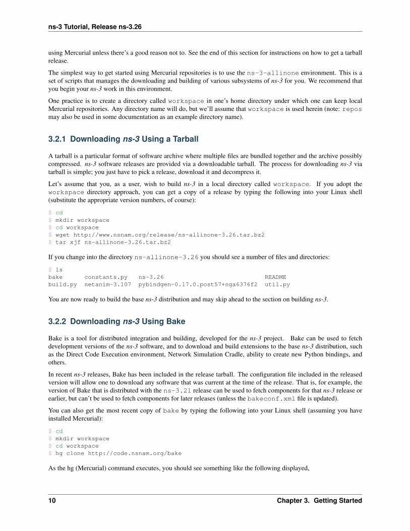
Let’s assume that you, as a user, wish to build ns-3 in a local directory called workspace. If you adopt theworkspace directory approach, you can get a copy of a release by typing the following into your Linux shell(substitute the appropriate version numbers, of course):
$ cd$ mkdir workspace$ cd workspace$ wget http://www.nsnam.org/release/ns-allinone-3.26.tar.bz2$ tar xjf ns-allinone-3.26.tar.bz2
If you change into the directory ns-allinone-3.26 you should see a number of files and directories:
$ lsbake constants.py ns-3.26 READMEbuild.py netanim-3.107 pybindgen-0.17.0.post57+nga6376f2 util.py
You are now ready to build the base ns-3 distribution and may skip ahead to the section on building ns-3.
3.2.2 Downloading ns-3 Using Bake
Bake is a tool for distributed integration and building, developed for the ns-3 project. Bake can be used to fetchdevelopment versions of the ns-3 software, and to download and build extensions to the base ns-3 distribution, suchas the Direct Code Execution environment, Network Simulation Cradle, ability to create new Python bindings, andothers.
In recent ns-3 releases, Bake has been included in the release tarball. The configuration file included in the releasedversion will allow one to download any software that was current at the time of the release. That is, for example, theversion of Bake that is distributed with the ns-3.21 release can be used to fetch components for that ns-3 release orearlier, but can’t be used to fetch components for later releases (unless the bakeconf.xml file is updated).
You can also get the most recent copy of bake by typing the following into your Linux shell (assuming you haveinstalled Mercurial):
$ cd$ mkdir workspace$ cd workspace$ hg clone http://code.nsnam.org/bake
As the hg (Mercurial) command executes, you should see something like the following displayed,
10 Chapter 3. Getting Started

ns-3 Tutorial, Release ns-3.26
...destination directory: bakerequesting all changesadding changesetsadding manifestsadding file changesadded 339 changesets with 796 changes to 63 filesupdating to branch default45 files updated, 0 files merged, 0 files removed, 0 files unresolved
After the clone command completes, you should have a directory called bake, the contents of which should looksomething like the following:
$ lsbake bakeconf.xml doc generate-binary.py TODObake.py examples test
Notice that you really just downloaded some Python scripts and a Python module called bake. The next step will beto use those scripts to download and build the ns-3 distribution of your choice.
There are a few configuration targets available:
1. ns-3.26: the module corresponding to the release; it will download components similar to the release tarball.
2. ns-3-dev: a similar module but using the development code tree
3. ns-allinone-3.26: the module that includes other optional features such as click routing, openflow forns-3, and the Network Simulation Cradle
4. ns-3-allinone: similar to the released version of the allinone module, but for development code.
The current development snapshot (unreleased) of ns-3 may be found at http://code.nsnam.org/ns-3-dev/. The devel-opers attempt to keep these repository in consistent, working states but they are in a development area with unreleasedcode present, so you may want to consider staying with an official release if you do not need newly- introducedfeatures.
You can find the latest version of the code either by inspection of the repository list or by going to the “ns-3 Releases”web page and clicking on the latest release link. We’ll proceed in this tutorial example with ns-3.26.
We are now going to use the bake tool to pull down the various pieces of ns-3 you will be using. First, we’ll say aword about running bake.
bake works by downloading source packages into a source directory, and installing libraries into a build directory. bakecan be run by referencing the binary, but if one chooses to run bake from outside of the directory it was downloadedinto, it is advisable to put bake into your path, such as follows (Linux bash shell example). First, change into the ‘bake’directory, and then set the following environment variables
$ export BAKE_HOME=`pwd`$ export PATH=$PATH:$BAKE_HOME:$BAKE_HOME/build/bin$ export PYTHONPATH=$PYTHONPATH:$BAKE_HOME:$BAKE_HOME/build/lib
This will put the bake.py program into the shell’s path, and will allow other programs to find executables and librariescreated by bake. Although several bake use cases do not require setting PATH and PYTHONPATH as above, fullbuilds of ns-3-allinone (with the optional packages) typically do.
Step into the workspace directory and type the following into your shell:
$ ./bake.py configure -e ns-3.26
Next, we’l ask bake to check whether we have enough tools to download various components. Type:
3.2. Downloading ns-3 11

ns-3 Tutorial, Release ns-3.26
$ ./bake.py check
You should see something like the following,
> Python - OK> GNU C++ compiler - OK> Mercurial - OK> CVS - OK> GIT - OK> Bazaar - OK> Tar tool - OK> Unzip tool - OK> Unrar tool - is missing> 7z data compression utility - OK> XZ data compression utility - OK> Make - OK> cMake - OK> patch tool - OK> autoreconf tool - OK
> Path searched for tools: /usr/lib64/qt-3.3/bin /usr/lib64/ccache/usr/local/bin /bin /usr/bin /usr/local/sbin /usr/sbin /sbin/home/tomh/bin bin
In particular, download tools such as Mercurial, CVS, GIT, and Bazaar are our principal concerns at this point, sincethey allow us to fetch the code. Please install missing tools at this stage, in the usual way for your system (if you areable to), or contact your system administrator as needed to install these tools.
Next, try to download the software:
$ ./bake.py download
should yield something like:
>> Downloading gccxml-ns3 (target directory:gccxml) - OK>> Searching for system dependency python-dev - OK>> Searching for system dependency pygraphviz - OK>> Searching for system dependency pygoocanvas - OK>> Searching for system dependency setuptools - OK>> Searching for system dependency g++ - OK>> Searching for system dependency qt4 - OK>> Downloading pygccxml - OK>> Downloading netanim-3.107 - OK>> Downloading pybindgen-0.17.0.post57+nga6376f2 (target directory:pybindgen) - OK>> Downloading ns-3.26 - OK
The above suggests that five sources have been downloaded. Check the source directory now and type ls; oneshould see:
$ lsgccxml netanim-3.107 ns-3.26 pybindgen pygccxml pygccxml-1.0.0.zip
You are now ready to build the ns-3 distribution.
12 Chapter 3. Getting Started

ns-3 Tutorial, Release ns-3.26
3.3 Building ns-3
3.3.1 Building with build.py
When working from a released tarball, the first time you build the ns-3 project you can build using a convenienceprogram found in the allinone directory. This program is called build.py. This program will get the projectconfigured for you in the most commonly useful way. However, please note that more advanced configuration andwork with ns-3 will typically involve using the native ns-3 build system, Waf, to be introduced later in this tutorial.
If you downloaded using a tarball you should have a directory called something like ns-allinone-3.26 underyour ~/workspace directory. Type the following:
$ ./build.py --enable-examples --enable-tests
Because we are working with examples and tests in this tutorial, and because they are not built by default in ns-3, thearguments for build.py tells it to build them for us. The program also defaults to building all available modules. Later,you can build ns-3 without examples and tests, or eliminate the modules that are not necessary for your work, if youwish.
You will see lots of typical compiler output messages displayed as the build script builds the various pieces youdownloaded. Eventually you should see the following:
Waf: Leaving directory `/path/to/workspace/ns-allinone-3.26/ns-3.26/build''build' finished successfully (6m25.032s)
Modules built:antenna aodv applicationsbridge buildings config-storecore csma csma-layoutdsdv dsr energyfd-net-device flow-monitor internetinternet-apps lr-wpan ltemesh mobility mpinetanim (no Python) network nix-vector-routingolsr openflow (no Python) point-to-pointpoint-to-point-layout propagation sixlowpanspectrum stats tap-bridgetest (no Python) topology-read traffic-controluan virtual-net-device visualizerwave wifi wimax
Modules not built (see ns-3 tutorial for explanation):brite click
Regarding the portion about modules not built:
Modules not built (see ns-3 tutorial for explanation):brite click
This just means that some ns-3 modules that have dependencies on outside libraries may not have been built, or thatthe configuration specifically asked not to build them. It does not mean that the simulator did not build successfully orthat it will provide wrong results for the modules listed as being built.
3.3.2 Building with bake
If you used bake above to fetch source code from project repositories, you may continue to use it to build ns-3. Type
3.3. Building ns-3 13
ns-3 Tutorial, Release ns-3.26
$ ./bake.py build
and you should see something like:
>> Building gccxml-ns3 - OK>> Building pygccxml - OK>> Building netanim-3.107 - OK>> Building pybindgen-0.17.0.post57+nga6376f2 - OK>> Building ns-3.26 - OK
Hint: you can also perform both steps, download and build, by calling ‘‘bake.py deploy‘‘.
If there happens to be a failure, please have a look at what the following command tells you; it may give a hint as to amissing dependency:
$ ./bake.py show
This will list out the various dependencies of the packages you are trying to build.
3.3.3 Building with Waf
Up to this point, we have used either the build.py script, or the bake tool, to get started with building ns-3. These toolsare useful for building ns-3 and supporting libraries, and they call into the ns-3 directory to call the Waf build tool todo the actual building. Most users quickly transition to using Waf directly to configure and build ns-3. So, to proceed,please change your working directory to the ns-3 directory that you have initially built.
It’s not strictly required at this point, but it will be valuable to take a slight detour and look at how to make changesto the configuration of the project. Probably the most useful configuration change you can make will be to build theoptimized version of the code. By default you have configured your project to build the debug version. Let’s tell theproject to make an optimized build. To explain to Waf that it should do optimized builds that include the examples andtests, you will need to execute the following commands:
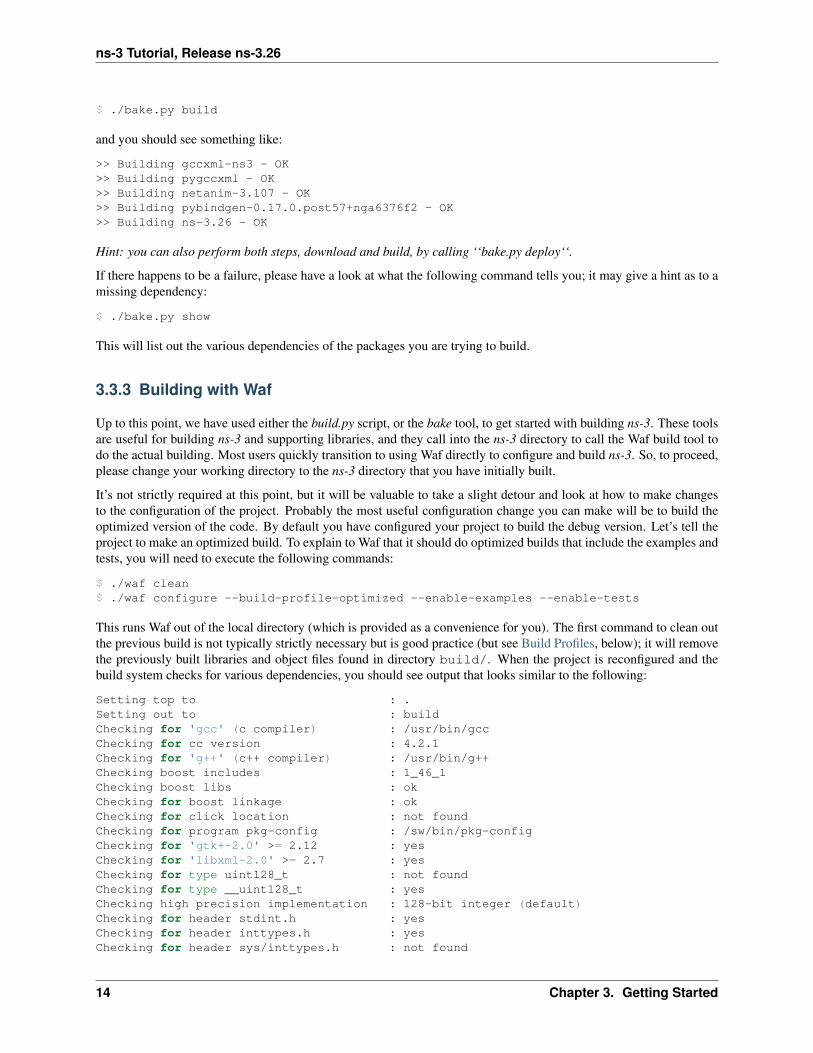
$ ./waf clean$ ./waf configure --build-profile=optimized --enable-examples --enable-tests
This runs Waf out of the local directory (which is provided as a convenience for you). The first command to clean outthe previous build is not typically strictly necessary but is good practice (but see Build Profiles, below); it will removethe previously built libraries and object files found in directory build/. When the project is reconfigured and thebuild system checks for various dependencies, you should see output that looks similar to the following:
Setting top to : .Setting out to : buildChecking for 'gcc' (c compiler) : /usr/bin/gccChecking for cc version : 4.2.1Checking for 'g++' (c++ compiler) : /usr/bin/g++Checking boost includes : 1_46_1Checking boost libs : okChecking for boost linkage : okChecking for click location : not foundChecking for program pkg-config : /sw/bin/pkg-configChecking for 'gtk+-2.0' >= 2.12 : yesChecking for 'libxml-2.0' >= 2.7 : yesChecking for type uint128_t : not foundChecking for type __uint128_t : yesChecking high precision implementation : 128-bit integer (default)Checking for header stdint.h : yesChecking for header inttypes.h : yesChecking for header sys/inttypes.h : not found
14 Chapter 3. Getting Started

ns-3 Tutorial, Release ns-3.26
Checking for header sys/types.h : yesChecking for header sys/stat.h : yesChecking for header dirent.h : yesChecking for header stdlib.h : yesChecking for header signal.h : yesChecking for header pthread.h : yesChecking for header stdint.h : yesChecking for header inttypes.h : yesChecking for header sys/inttypes.h : not foundChecking for library rt : not foundChecking for header netpacket/packet.h : not foundChecking for header sys/ioctl.h : yesChecking for header net/if.h : not foundChecking for header net/ethernet.h : yesChecking for header linux/if_tun.h : not foundChecking for header netpacket/packet.h : not foundChecking for NSC location : not foundChecking for 'mpic++' : yesChecking for 'sqlite3' : yesChecking for header linux/if_tun.h : not foundChecking for program sudo : /usr/bin/sudoChecking for program valgrind : /sw/bin/valgrindChecking for 'gsl' : yesChecking for compilation flag -Wno-error=deprecated-d... support : okChecking for compilation flag -Wno-error=deprecated-d... support : okChecking for compilation flag -fstrict-aliasing... support : okChecking for compilation flag -fstrict-aliasing... support : okChecking for compilation flag -Wstrict-aliasing... support : okChecking for compilation flag -Wstrict-aliasing... support : okChecking for program doxygen : /usr/local/bin/doxygen---- Summary of optional NS-3 features:Build profile : debugBRITE Integration : not enabled (BRITE not enabled (see option --with-brite))Build directory : buildBuild examples : enabledBuild tests : enabledEmulated Net Device : enabled (<netpacket/packet.h> include not detected)Emulation FdNetDevice : not enabled (needs netpacket/packet.h)File descriptor NetDevice : enabledGNU Scientific Library (GSL) : enabledGtkConfigStore : enabledMPI Support : enabledNS-3 Click Integration : not enabled (nsclick not enabled (see option --with-nsclick))NS-3 OpenFlow Integration : not enabled (Required boost libraries not found, missing: system, signals, filesystem)Network Simulation Cradle : not enabled (NSC not found (see option --with-nsc))PlanetLab FdNetDevice : not enabled (PlanetLab operating system not detected (see option --force-planetlab))PyViz visualizer : enabledPython Bindings : enabledReal Time Simulator : enabled (librt is not available)SQlite stats data output : enabledTap Bridge : not enabled (<linux/if_tun.h> include not detected)Tap FdNetDevice : not enabled (needs linux/if_tun.h)Threading Primitives : enabledUse sudo to set suid bit : not enabled (option --enable-sudo not selected)XmlIo : enabled'configure' finished successfully (1.944s)
Note the last part of the above output. Some ns-3 options are not enabled by default or require support from the
3.3. Building ns-3 15

ns-3 Tutorial, Release ns-3.26
underlying system to work properly. For instance, to enable XmlTo, the library libxml-2.0 must be found on thesystem. If this library were not found, the corresponding ns-3 feature would not be enabled and a message would bedisplayed. Note further that there is a feature to use the program sudo to set the suid bit of certain programs. Thisis not enabled by default and so this feature is reported as “not enabled.” Finally, to reprint this summary of whichoptional features are enabled, use the --check-config option to waf.
Now go ahead and switch back to the debug build that includes the examples and tests.
$ ./waf clean$ ./waf configure --build-profile=debug --enable-examples --enable-tests
The build system is now configured and you can build the debug versions of the ns-3 programs by simply typing
$ ./waf
Okay, sorry, I made you build the ns-3 part of the system twice, but now you know how to change the configurationand build optimized code.
A command exists for checking which profile is currently active for an already configured project:
$ ./waf --check-profileWaf: Entering directory \`/path/to/ns-3-allinone/ns-3.26/build'Build profile: debug
The build.py script discussed above supports also the --enable-examples and enable-tests arguments, butin general, does not directly support other waf options; for example, this will not work:
$ ./build.py --disable-python
will result in
build.py: error: no such option: --disable-python
However, the special operator -- can be used to pass additional options through to waf, so instead of the above, thefollowing will work:
$ ./build.py -- --disable-python
as it generates the underlying command ./waf configure --disable-python.
Here are a few more introductory tips about Waf.
Configure vs. Build
Some Waf commands are only meaningful during the configure phase and some commands are valid in the buildphase. For example, if you wanted to use the emulation features of ns-3, you might want to enable setting the suidbit using sudo as described above. This turns out to be a configuration-time command, and so you could reconfigureusing the following command that also includes the examples and tests.
$ ./waf configure --enable-sudo --enable-examples --enable-tests
If you do this, Waf will have run sudo to change the socket creator programs of the emulation code to run as root.
There are many other configure- and build-time options available in Waf. To explore these options, type:
$ ./waf --help
We’ll use some of the testing-related commands in the next section.
16 Chapter 3. Getting Started

ns-3 Tutorial, Release ns-3.26
Build Profiles
We already saw how you can configure Waf for debug or optimized builds:
$ ./waf --build-profile=debug
There is also an intermediate build profile, release. -d is a synonym for --build-profile.
The build profile controls the use of logging, assertions, and compiler optimization:
Feature Build Profiledebug release optimized
Enabled Features
NS3_BUILD_PROFILE_DEBUG
NS_LOG...
NS_ASSERT...
NS3_BUILD_PROFILE_RELEASENS3_BUILD_PROFILE_OPTIMIZED
Code Wrapper Macro NS_BUILD_DEBUG(code) NS_BUILD_RELEASE(code)NS_BUILD_OPTIMIZED(code)Compiler Flags -O0 -ggdb -g3 -O3 -g0
-fomit-frame-pointer-O3 -g-fstrict-overflow-march=native
As you can see, logging and assertions are only available in debug builds. Recommended practice is to develop yourscenario in debug mode, then conduct repetitive runs (for statistics or changing parameters) in optimized build profile.
If you have code that should only run in specific build profiles, use the indicated Code Wrapper macro:
NS_BUILD_DEBUG (std::cout << "Part of an output line..." << std::flush; timer.Start ());DoLongInvolvedComputation ();NS_BUILD_DEBUG (timer.Stop (); std::cout << "Done: " << timer << std::endl;)
By default Waf puts the build artifacts in the build directory. You can specify a different output directory with the--out option, e.g.
$ ./waf configure --out=foo
Combining this with build profiles lets you switch between the different compile options in a clean way:
$ ./waf configure --build-profile=debug --out=build/debug$ ./waf build...$ ./waf configure --build-profile=optimized --out=build/optimized$ ./waf build...
This allows you to work with multiple builds rather than always overwriting the last build. When you switch, Waf willonly compile what it has to, instead of recompiling everything.
When you do switch build profiles like this, you have to be careful to give the same configuration parameters eachtime. It may be convenient to define some environment variables to help you avoid mistakes:
$ export NS3CONFIG="--enable-examples --enable-tests"$ export NS3DEBUG="--build-profile=debug --out=build/debug"$ export NS3OPT=="--build-profile=optimized --out=build/optimized"
$ ./waf configure $NS3CONFIG $NS3DEBUG$ ./waf build...
3.3. Building ns-3 17

ns-3 Tutorial, Release ns-3.26
$ ./waf configure $NS3CONFIG $NS3OPT$ ./waf build
Compilers and Flags
In the examples above, Waf uses the GCC C++ compiler, g++, for building ns-3. However, it’s possible to change theC++ compiler used by Waf by defining the CXX environment variable. For example, to use the Clang C++ compiler,clang++,
$ CXX="clang++" ./waf configure$ ./waf build
One can also set up Waf to do distributed compilation with distcc in a similar way:
$ CXX="distcc g++" ./waf configure$ ./waf build
More info on distcc and distributed compilation can be found on it’s project page under Documentation section.
To add compiler flags, use the CXXFLAGS_EXTRA environment variable when you configure ns-3.
Install
Waf may be used to install libraries in various places on the system. The default location where libraries and executa-bles are built is in the build directory, and because Waf knows the location of these libraries and executables, it isnot necessary to install the libraries elsewhere.
If users choose to install things outside of the build directory, users may issue the ./waf install com-mand. By default, the prefix for installation is /usr/local, so ./waf install will install programs into/usr/local/bin, libraries into /usr/local/lib, and headers into /usr/local/include. Superuserprivileges are typically needed to install to the default prefix, so the typical command would be sudo ./wafinstall. When running programs with Waf, Waf will first prefer to use shared libraries in the build directory,then will look for libraries in the library path configured in the local environment. So when installing libraries to thesystem, it is good practice to check that the intended libraries are being used.
Users may choose to install to a different prefix by passing the --prefix option at configure time, such as:
./waf configure --prefix=/opt/local
If later after the build the user issues the ./waf install command, the prefix /opt/local will be used.
The ./waf clean command should be used prior to reconfiguring the project if Waf will be used to install thingsat a different prefix.
In summary, it is not necessary to call ./waf install to use ns-3. Most users will not need this command sinceWaf will pick up the current libraries from the build directory, but some users may find it useful if their use caseinvolves working with programs outside of the ns-3 directory.
One Waf
There is only one Waf script, at the top level of the ns-3 source tree. As you work, you may find yourself spending alot of time in scratch/, or deep in src/..., and needing to invoke Waf. You could just remember where you are,and invoke Waf like this:
$ ../../../waf ...
18 Chapter 3. Getting Started

ns-3 Tutorial, Release ns-3.26
but that gets tedious, and error prone, and there are better solutions.
If you have the full ns-3 repository this little gem is a start:
$ cd $(hg root) && ./waf ...
Even better is to define this as a shell function:
$ function waff { cd $(hg root) && ./waf $* ; }
$ waff build
If you only have the tarball, an environment variable can help:
$ export NS3DIR="$PWD"$ function waff { cd $NS3DIR && ./waf $* ; }
$ cd scratch$ waff build
It might be tempting in a module directory to add a trivial waf script along the lines of exec ../../waf. Pleasedon’t. It’s confusing to new-comers, and when done poorly it leads to subtle build errors. The solutions above are theway to go.
3.4 Testing ns-3
You can run the unit tests of the ns-3 distribution by running the ./test.py -c core script:
$ ./test.py -c core
These tests are run in parallel by Waf. You should eventually see a report saying that
92 of 92 tests passed (92 passed, 0 failed, 0 crashed, 0 valgrind errors)
This is the important message.
You will also see the summary output from Waf and the test runner executing each test, which will actually looksomething like:
Waf: Entering directory `/path/to/workspace/ns-3-allinone/ns-3-dev/build'Waf: Leaving directory `/path/to/workspace/ns-3-allinone/ns-3-dev/build''build' finished successfully (1.799s)
Modules built:aodv applications bridgeclick config-store corecsma csma-layout dsdvemu energy flow-monitorinternet lte meshmobility mpi netanimnetwork nix-vector-routing ns3tcpns3wifi olsr openflowpoint-to-point point-to-point-layout propagationspectrum stats tap-bridgetemplate test toolstopology-read uan virtual-net-devicevisualizer wifi wimax
3.4. Testing ns-3 19

ns-3 Tutorial, Release ns-3.26
PASS: TestSuite ns3-wifi-interferencePASS: TestSuite histogram
...
PASS: TestSuite objectPASS: TestSuite random-number-generators92 of 92 tests passed (92 passed, 0 failed, 0 crashed, 0 valgrind errors)
This command is typically run by users to quickly verify that an ns-3 distribution has built correctly. (Note the orderof the PASS: ... lines can vary, which is okay. What’s important is that the summary line at the end report that alltests passed; none failed or crashed.)
3.5 Running a Script
We typically run scripts under the control of Waf. This allows the build system to ensure that the shared library pathsare set correctly and that the libraries are available at run time. To run a program, simply use the --run option inWaf. Let’s run the ns-3 equivalent of the ubiquitous hello world program by typing the following:
$ ./waf --run hello-simulator
Waf first checks to make sure that the program is built correctly and executes a build if required. Waf then executesthe program, which produces the following output.
Hello Simulator
Congratulations! You are now an ns-3 user!
What do I do if I don’t see the output?
If you see Waf messages indicating that the build was completed successfully, but do not see the “Hello Simulator”output, chances are that you have switched your build mode to optimized in the Building with Waf section, but havemissed the change back to debug mode. All of the console output used in this tutorial uses a special ns-3 loggingcomponent that is useful for printing user messages to the console. Output from this component is automaticallydisabled when you compile optimized code – it is “optimized out.” If you don’t see the “Hello Simulator” output, typethe following:
$ ./waf configure --build-profile=debug --enable-examples --enable-tests
to tell Waf to build the debug versions of the ns-3 programs that includes the examples and tests. You must still buildthe actual debug version of the code by typing
$ ./waf
Now, if you run the hello-simulator program, you should see the expected output.
3.5.1 Program Arguments
To feed command line arguments to an ns-3 program use this pattern:
$ ./waf --run <ns3-program> --command-template="%s <args>"
Substitute your program name for <ns3-program>, and the arguments for <args>. The--command-template argument to Waf is basically a recipe for constructing the actual command line Wafshould use to execute the program. Waf checks that the build is complete, sets the shared library paths, then invokes
20 Chapter 3. Getting Started

ns-3 Tutorial, Release ns-3.26
the executable using the provided command line template, inserting the program name for the %s placeholder. (Iadmit this is a bit awkward, but that’s the way it is. Patches welcome!)
Another particularly useful example is to run a test suite by itself. Let’s assume that a mytest test suite exists (itdoesn’t). Above, we used the ./test.py script to run a whole slew of tests in parallel, by repeatedly invoking thereal testing program, test-runner. To invoke test-runner directly for a single test:
$ ./waf --run test-runner --command-template="%s --suite=mytest --verbose"
This passes the arguments to the test-runner program. Since mytest does not exist, an error message will begenerated. To print the available test-runner options:
$ ./waf --run test-runner --command-template="%s --help"
3.5.2 Debugging
To run ns-3 programs under the control of another utility, such as a debugger (e.g. gdb) or memory checker (e.g.valgrind), you use a similar --command-template="..." form.
For example, to run your ns-3 program hello-simulator with the arguments <args> under the gdb debugger:
$ ./waf --run=hello-simulator --command-template="gdb %s --args <args>"
Notice that the ns-3 program name goes with the --run argument, and the control utility (here gdb) is the firsttoken in the --commmand-template argument. The --args tells gdb that the remainder of the command linebelongs to the “inferior” program. (Some gdb‘s don’t understand the --args feature. In this case, omit the programarguments from the --command-template, and use the gdb command set args.)
We can combine this recipe and the previous one to run a test under the debugger:
$ ./waf --run test-runner --command-template="gdb %s --args --suite=mytest --verbose"
3.5.3 Working Directory
Waf needs to run from its location at the top of the ns-3 tree. This becomes the working directory where output fileswill be written. But what if you want to keep those ouf to the ns-3 source tree? Use the --cwd argument:
$ ./waf --cwd=...
It may be more convenient to start with your working directory where you want the output files, in which case a littleindirection can help:
$ function waff {CWD="$PWD"cd $NS3DIR >/dev/null./waf --cwd="$CWD" $*cd - >/dev/null
}
This embellishment of the previous version saves the current working directory, cd‘s to the Waf directory, then in-structs Waf to change the working directory back to the saved current working directory before running the program.
3.5. Running a Script 21

ns-3 Tutorial, Release ns-3.26
22 Chapter 3. Getting Started

CHAPTER
FOUR
CONCEPTUAL OVERVIEW
The first thing we need to do before actually starting to look at or write ns-3 code is to explain a few core conceptsand abstractions in the system. Much of this may appear transparently obvious to some, but we recommend taking thetime to read through this section just to ensure you are starting on a firm foundation.
4.1 Key Abstractions
In this section, we’ll review some terms that are commonly used in networking, but have a specific meaning in ns-3.
4.1.1 Node
In Internet jargon, a computing device that connects to a network is called a host or sometimes an end system. Becausens-3 is a network simulator, not specifically an Internet simulator, we intentionally do not use the term host sinceit is closely associated with the Internet and its protocols. Instead, we use a more generic term also used by othersimulators that originates in Graph Theory — the node.
In ns-3 the basic computing device abstraction is called the node. This abstraction is represented in C++ by the classNode. The Node class provides methods for managing the representations of computing devices in simulations.
You should think of a Node as a computer to which you will add functionality. One adds things like applications,protocol stacks and peripheral cards with their associated drivers to enable the computer to do useful work. We usethe same basic model in ns-3.
4.1.2 Application
Typically, computer software is divided into two broad classes. System Software organizes various computer resourcessuch as memory, processor cycles, disk, network, etc., according to some computing model. System software usuallydoes not use those resources to complete tasks that directly benefit a user. A user would typically run an applicationthat acquires and uses the resources controlled by the system software to accomplish some goal.
Often, the line of separation between system and application software is made at the privilege level change that happensin operating system traps. In ns-3 there is no real concept of operating system and especially no concept of privilegelevels or system calls. We do, however, have the idea of an application. Just as software applications run on computersto perform tasks in the “real world,” ns-3 applications run on ns-3 Nodes to drive simulations in the simulated world.
In ns-3 the basic abstraction for a user program that generates some activity to be simulated is the application.This abstraction is represented in C++ by the class Application. The Application class provides meth-ods for managing the representations of our version of user-level applications in simulations. Developers are ex-pected to specialize the Application class in the object-oriented programming sense to create new applications.In this tutorial, we will use specializations of class Application called UdpEchoClientApplication and
23

ns-3 Tutorial, Release ns-3.26
UdpEchoServerApplication. As you might expect, these applications compose a client/server application setused to generate and echo simulated network packets
4.1.3 Channel
In the real world, one can connect a computer to a network. Often the media over which data flows in these networksare called channels. When you connect your Ethernet cable to the plug in the wall, you are connecting your computerto an Ethernet communication channel. In the simulated world of ns-3, one connects a Node to an object representing acommunication channel. Here the basic communication subnetwork abstraction is called the channel and is representedin C++ by the class Channel.
The Channel class provides methods for managing communication subnetwork objects and connecting nodes tothem. Channels may also be specialized by developers in the object oriented programming sense. A Channel spe-cialization may model something as simple as a wire. The specialized Channel can also model things as complicatedas a large Ethernet switch, or three-dimensional space full of obstructions in the case of wireless networks.
We will use specialized versions of the Channel called CsmaChannel, PointToPointChannel andWifiChannel in this tutorial. The CsmaChannel, for example, models a version of a communication subnetworkthat implements a carrier sense multiple access communication medium. This gives us Ethernet-like functionality.
4.1.4 Net Device
It used to be the case that if you wanted to connect a computer to a network, you had to buy a specific kind of networkcable and a hardware device called (in PC terminology) a peripheral card that needed to be installed in your computer.If the peripheral card implemented some networking function, they were called Network Interface Cards, or NICs.Today most computers come with the network interface hardware built in and users don’t see these building blocks.
A NIC will not work without a software driver to control the hardware. In Unix (or Linux), a piece of peripheral hard-ware is classified as a device. Devices are controlled using device drivers, and network devices (NICs) are controlledusing network device drivers collectively known as net devices. In Unix and Linux you refer to these net devices bynames such as eth0.
In ns-3 the net device abstraction covers both the software driver and the simulated hardware. A net device is “in-stalled” in a Node in order to enable the Node to communicate with other Nodes in the simulation via Channels.Just as in a real computer, a Node may be connected to more than one Channel via multiple NetDevices.
The net device abstraction is represented in C++ by the class NetDevice. The NetDevice class providesmethods for managing connections to Node and Channel objects; and may be specialized by developers inthe object-oriented programming sense. We will use the several specialized versions of the NetDevice calledCsmaNetDevice, PointToPointNetDevice, and WifiNetDevice in this tutorial. Just as an Ethernet NICis designed to work with an Ethernet network, the CsmaNetDevice is designed to work with a CsmaChannel; thePointToPointNetDevice is designed to work with a PointToPointChannel and a WifiNetNevice isdesigned to work with a WifiChannel.
4.1.5 Topology Helpers
In a real network, you will find host computers with added (or built-in) NICs. In ns-3 we would say that you willfind Nodes with attached NetDevices. In a large simulated network you will need to arrange many connectionsbetween Nodes, NetDevices and Channels.
Since connecting NetDevices to Nodes, NetDevices to Channels, assigning IP addresses, etc., are suchcommon tasks in ns-3, we provide what we call topology helpers to make this as easy as possible. For example, it maytake many distinct ns-3 core operations to create a NetDevice, add a MAC address, install that net device on a Node,configure the node’s protocol stack, and then connect the NetDevice to a Channel. Even more operations would
24 Chapter 4. Conceptual Overview
ns-3 Tutorial, Release ns-3.26
be required to connect multiple devices onto multipoint channels and then to connect individual networks together intointernetworks. We provide topology helper objects that combine those many distinct operations into an easy to usemodel for your convenience.
4.2 A First ns-3 Script
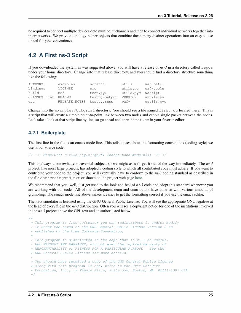
If you downloaded the system as was suggested above, you will have a release of ns-3 in a directory called reposunder your home directory. Change into that release directory, and you should find a directory structure somethinglike the following:
AUTHORS examples scratch utils waf.bat*bindings LICENSE src utils.py waf-toolsbuild ns3 test.py* utils.pyc wscriptCHANGES.html README testpy-output VERSION wutils.pydoc RELEASE_NOTES testpy.supp waf* wutils.pyc
Change into the examples/tutorial directory. You should see a file named first.cc located there. This isa script that will create a simple point-to-point link between two nodes and echo a single packet between the nodes.Let’s take a look at that script line by line, so go ahead and open first.cc in your favorite editor.
4.2.1 Boilerplate
The first line in the file is an emacs mode line. This tells emacs about the formatting conventions (coding style) weuse in our source code.
/* -*- Mode:C++; c-file-style:"gnu"; indent-tabs-mode:nil; -*- */
This is always a somewhat controversial subject, so we might as well get it out of the way immediately. The ns-3project, like most large projects, has adopted a coding style to which all contributed code must adhere. If you want tocontribute your code to the project, you will eventually have to conform to the ns-3 coding standard as described inthe file doc/codingstd.txt or shown on the project web page here.
We recommend that you, well, just get used to the look and feel of ns-3 code and adopt this standard whenever youare working with our code. All of the development team and contributors have done so with various amounts ofgrumbling. The emacs mode line above makes it easier to get the formatting correct if you use the emacs editor.
The ns-3 simulator is licensed using the GNU General Public License. You will see the appropriate GNU legalese atthe head of every file in the ns-3 distribution. Often you will see a copyright notice for one of the institutions involvedin the ns-3 project above the GPL text and an author listed below.
/** This program is free software; you can redistribute it and/or modify
* it under the terms of the GNU General Public License version 2 as
* published by the Free Software Foundation;
** This program is distributed in the hope that it will be useful,
* but WITHOUT ANY WARRANTY; without even the implied warranty of
* MERCHANTABILITY or FITNESS FOR A PARTICULAR PURPOSE. See the
* GNU General Public License for more details.
** You should have received a copy of the GNU General Public License
* along with this program; if not, write to the Free Software
* Foundation, Inc., 59 Temple Place, Suite 330, Boston, MA 02111-1307 USA
*/
4.2. A First ns-3 Script 25

ns-3 Tutorial, Release ns-3.26
4.2.2 Module Includes
The code proper starts with a number of include statements.
#include "ns3/core-module.h"#include "ns3/network-module.h"#include "ns3/internet-module.h"#include "ns3/point-to-point-module.h"#include "ns3/applications-module.h"
To help our high-level script users deal with the large number of include files present in the system, we group includesaccording to relatively large modules. We provide a single include file that will recursively load all of the includefiles used in each module. Rather than having to look up exactly what header you need, and possibly have to get anumber of dependencies right, we give you the ability to load a group of files at a large granularity. This is not themost efficient approach but it certainly makes writing scripts much easier.
Each of the ns-3 include files is placed in a directory called ns3 (under the build directory) during the build processto help avoid include file name collisions. The ns3/core-module.h file corresponds to the ns-3 module you willfind in the directory src/core in your downloaded release distribution. If you list this directory you will find alarge number of header files. When you do a build, Waf will place public header files in an ns3 directory underthe appropriate build/debug or build/optimized directory depending on your configuration. Waf will alsoautomatically generate a module include file to load all of the public header files.
Since you are, of course, following this tutorial religiously, you will already have done a
$ ./waf -d debug --enable-examples --enable-tests configure
in order to configure the project to perform debug builds that include examples and tests. You will also have done a
$ ./waf
to build the project. So now if you look in the directory ../../build/debug/ns3 you will find the four moduleinclude files shown above. You can take a look at the contents of these files and find that they do include all of thepublic include files in their respective modules.
4.2.3 Ns3 Namespace
The next line in the first.cc script is a namespace declaration.
using namespace ns3;
The ns-3 project is implemented in a C++ namespace called ns3. This groups all ns-3-related declarations in a scopeoutside the global namespace, which we hope will help with integration with other code. The C++ using statementintroduces the ns-3 namespace into the current (global) declarative region. This is a fancy way of saying that after thisdeclaration, you will not have to type ns3:: scope resolution operator before all of the ns-3 code in order to use it.If you are unfamiliar with namespaces, please consult almost any C++ tutorial and compare the ns3 namespace andusage here with instances of the std namespace and the using namespace std; statements you will often findin discussions of cout and streams.
4.2.4 Logging
The next line of the script is the following,
NS_LOG_COMPONENT_DEFINE ("FirstScriptExample");
26 Chapter 4. Conceptual Overview

ns-3 Tutorial, Release ns-3.26
We will use this statement as a convenient place to talk about our Doxygen documentation system. If you look at theproject web site, ns-3 project, you will find a link to “Documentation” in the navigation bar. If you select this link, youwill be taken to our documentation page. There is a link to “Latest Release” that will take you to the documentationfor the latest stable release of ns-3. If you select the “API Documentation” link, you will be taken to the ns-3 APIdocumentation page.
Along the left side, you will find a graphical representation of the structure of the documentation. A good place tostart is the NS-3 Modules “book” in the ns-3 navigation tree. If you expand Modules you will see a list of ns-3module documentation. The concept of module here ties directly into the module include files discussed above. Thens-3 logging subsystem is discussed in the Using the Logging Module section, so we’ll get to it later in this tutorial, butyou can find out about the above statement by looking at the Core module, then expanding the Debugging toolsbook, and then selecting the Logging page. Click on Logging.
You should now be looking at the Doxygen documentation for the Logging module. In the list of Macros‘s at thetop of the page you will see the entry for NS_LOG_COMPONENT_DEFINE. Before jumping in, it would probablybe good to look for the “Detailed Description” of the logging module to get a feel for the overall operation. You caneither scroll down or select the “More...” link under the collaboration diagram to do this.
Once you have a general idea of what is going on, go ahead and take a look at the specificNS_LOG_COMPONENT_DEFINE documentation. I won’t duplicate the documentation here, but to summarize, thisline declares a logging component called FirstScriptExample that allows you to enable and disable consolemessage logging by reference to the name.
4.2.5 Main Function
The next lines of the script you will find are,
intmain (int argc, char *argv[]){
This is just the declaration of the main function of your program (script). Just as in any C++ program, you need todefine a main function that will be the first function run. There is nothing at all special here. Your ns-3 script is just aC++ program.
The next line sets the time resolution to one nanosecond, which happens to be the default value:
Time::SetResolution (Time::NS);
The resolution is the smallest time value that can be represented (as well as the smallest representable differencebetween two time values). You can change the resolution exactly once. The mechanism enabling this flexibility issomewhat memory hungry, so once the resolution has been set explicitly we release the memory, preventing furtherupdates. (If you don’t set the resolution explicitly, it will default to one nanosecond, and the memory will be releasedwhen the simulation starts.)
The next two lines of the script are used to enable two logging components that are built into the Echo Client and EchoServer applications:
LogComponentEnable("UdpEchoClientApplication", LOG_LEVEL_INFO);LogComponentEnable("UdpEchoServerApplication", LOG_LEVEL_INFO);
If you have read over the Logging component documentation you will have seen that there are a number of levels oflogging verbosity/detail that you can enable on each component. These two lines of code enable debug logging at theINFO level for echo clients and servers. This will result in the application printing out messages as packets are sentand received during the simulation.
Now we will get directly to the business of creating a topology and running a simulation. We use the topology helperobjects to make this job as easy as possible.
4.2. A First ns-3 Script 27

ns-3 Tutorial, Release ns-3.26
4.2.6 Topology Helpers
NodeContainer
The next two lines of code in our script will actually create the ns-3 Node objects that will represent the computers inthe simulation.
NodeContainer nodes;nodes.Create (2);
Let’s find the documentation for the NodeContainer class before we continue. Another way to get into the doc-umentation for a given class is via the Classes tab in the Doxygen pages. If you still have the Doxygen handy,just scroll up to the top of the page and select the Classes tab. You should see a new set of tabs appear, oneof which is Class List. Under that tab you will see a list of all of the ns-3 classes. Scroll down, looking forns3::NodeContainer. When you find the class, go ahead and select it to go to the documentation for the class.
You may recall that one of our key abstractions is the Node. This represents a computer to which we are going toadd things like protocol stacks, applications and peripheral cards. The NodeContainer topology helper provides aconvenient way to create, manage and access any Node objects that we create in order to run a simulation. The firstline above just declares a NodeContainer which we call nodes. The second line calls the Create method on thenodes object and asks the container to create two nodes. As described in the Doxygen, the container calls down intothe ns-3 system proper to create two Node objects and stores pointers to those objects internally.
The nodes as they stand in the script do nothing. The next step in constructing a topology is to connect our nodestogether into a network. The simplest form of network we support is a single point-to-point link between two nodes.We’ll construct one of those links here.
PointToPointHelper
We are constructing a point to point link, and, in a pattern which will become quite familiar to you, we use a topologyhelper object to do the low-level work required to put the link together. Recall that two of our key abstractionsare the NetDevice and the Channel. In the real world, these terms correspond roughly to peripheral cards andnetwork cables. Typically these two things are intimately tied together and one cannot expect to interchange, forexample, Ethernet devices and wireless channels. Our Topology Helpers follow this intimate coupling and thereforeyou will use a single PointToPointHelper to configure and connect ns-3 PointToPointNetDevice andPointToPointChannel objects in this script.
The next three lines in the script are,
PointToPointHelper pointToPoint;pointToPoint.SetDeviceAttribute ("DataRate", StringValue ("5Mbps"));pointToPoint.SetChannelAttribute ("Delay", StringValue ("2ms"));
The first line,
PointToPointHelper pointToPoint;
instantiates a PointToPointHelper object on the stack. From a high-level perspective the next line,
pointToPoint.SetDeviceAttribute ("DataRate", StringValue ("5Mbps"));
tells the PointToPointHelper object to use the value “5Mbps” (five megabits per second) as the “DataRate”when it creates a PointToPointNetDevice object.
From a more detailed perspective, the string “DataRate” corresponds to what we call an Attribute of thePointToPointNetDevice. If you look at the Doxygen for class ns3::PointToPointNetDevice and findthe documentation for the GetTypeId method, you will find a list of Attributes defined for the device. Among
28 Chapter 4. Conceptual Overview

ns-3 Tutorial, Release ns-3.26
these is the “DataRate” Attribute. Most user-visible ns-3 objects have similar lists of Attributes. We use thismechanism to easily configure simulations without recompiling as you will see in a following section.
Similar to the “DataRate” on the PointToPointNetDevice you will find a “Delay” Attribute associated withthe PointToPointChannel. The final line,
pointToPoint.SetChannelAttribute ("Delay", StringValue ("2ms"));
tells the PointToPointHelper to use the value “2ms” (two milliseconds) as the value of the propagation delay ofevery point to point channel it subsequently creates.
NetDeviceContainer
At this point in the script, we have a NodeContainer that contains two nodes. We have a PointToPointHelperthat is primed and ready to make PointToPointNetDevices and wire PointToPointChannel objects be-tween them. Just as we used the NodeContainer topology helper object to create the Nodes for our simulation,we will ask the PointToPointHelper to do the work involved in creating, configuring and installing our devicesfor us. We will need to have a list of all of the NetDevice objects that are created, so we use a NetDeviceContainer tohold them just as we used a NodeContainer to hold the nodes we created. The following two lines of code,
NetDeviceContainer devices;devices = pointToPoint.Install (nodes);
will finish configuring the devices and channel. The first line declares the device container mentioned above and thesecond does the heavy lifting. The Install method of the PointToPointHelper takes a NodeContainer asa parameter. Internally, a NetDeviceContainer is created. For each node in the NodeContainer (there mustbe exactly two for a point-to-point link) a PointToPointNetDevice is created and saved in the device container.A PointToPointChannel is created and the two PointToPointNetDevices are attached. When objectsare created by the PointToPointHelper, the Attributes previously set in the helper are used to initialize thecorresponding Attributes in the created objects.
After executing the pointToPoint.Install (nodes) call we will have two nodes, each with an installedpoint-to-point net device and a single point-to-point channel between them. Both devices will be configured to transmitdata at five megabits per second over the channel which has a two millisecond transmission delay.
InternetStackHelper
We now have nodes and devices configured, but we don’t have any protocol stacks installed on our nodes. The nexttwo lines of code will take care of that.
InternetStackHelper stack;stack.Install (nodes);
The InternetStackHelper is a topology helper that is to internet stacks what the PointToPointHelper isto point-to-point net devices. The Install method takes a NodeContainer as a parameter. When it is executed,it will install an Internet Stack (TCP, UDP, IP, etc.) on each of the nodes in the node container.
Ipv4AddressHelper
Next we need to associate the devices on our nodes with IP addresses. We provide a topology helper to manage theallocation of IP addresses. The only user-visible API is to set the base IP address and network mask to use whenperforming the actual address allocation (which is done at a lower level inside the helper).
The next two lines of code in our example script, first.cc,
4.2. A First ns-3 Script 29
ns-3 Tutorial, Release ns-3.26
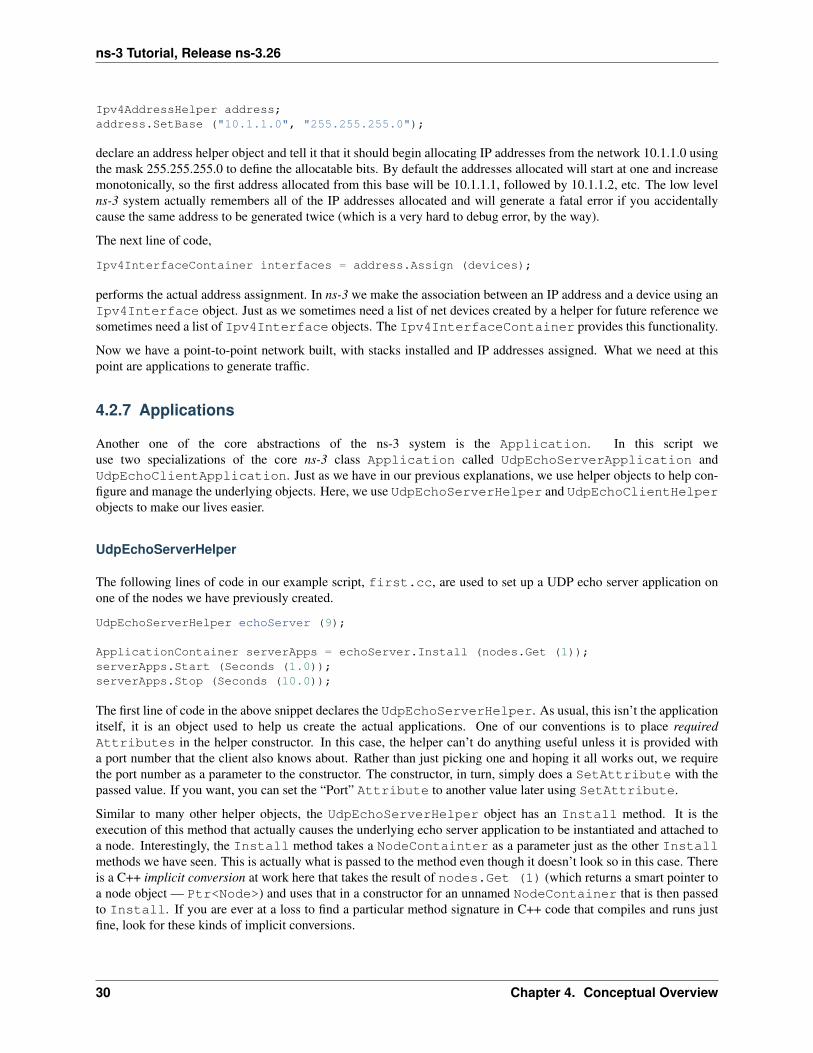
Ipv4AddressHelper address;address.SetBase ("10.1.1.0", "255.255.255.0");
declare an address helper object and tell it that it should begin allocating IP addresses from the network 10.1.1.0 usingthe mask 255.255.255.0 to define the allocatable bits. By default the addresses allocated will start at one and increasemonotonically, so the first address allocated from this base will be 10.1.1.1, followed by 10.1.1.2, etc. The low levelns-3 system actually remembers all of the IP addresses allocated and will generate a fatal error if you accidentallycause the same address to be generated twice (which is a very hard to debug error, by the way).
The next line of code,
Ipv4InterfaceContainer interfaces = address.Assign (devices);
performs the actual address assignment. In ns-3 we make the association between an IP address and a device using anIpv4Interface object. Just as we sometimes need a list of net devices created by a helper for future reference wesometimes need a list of Ipv4Interface objects. The Ipv4InterfaceContainer provides this functionality.
Now we have a point-to-point network built, with stacks installed and IP addresses assigned. What we need at thispoint are applications to generate traffic.
4.2.7 Applications
Another one of the core abstractions of the ns-3 system is the Application. In this script weuse two specializations of the core ns-3 class Application called UdpEchoServerApplication andUdpEchoClientApplication. Just as we have in our previous explanations, we use helper objects to help con-figure and manage the underlying objects. Here, we use UdpEchoServerHelper and UdpEchoClientHelperobjects to make our lives easier.
UdpEchoServerHelper
The following lines of code in our example script, first.cc, are used to set up a UDP echo server application onone of the nodes we have previously created.
UdpEchoServerHelper echoServer (9);
ApplicationContainer serverApps = echoServer.Install (nodes.Get (1));serverApps.Start (Seconds (1.0));serverApps.Stop (Seconds (10.0));
The first line of code in the above snippet declares the UdpEchoServerHelper. As usual, this isn’t the applicationitself, it is an object used to help us create the actual applications. One of our conventions is to place requiredAttributes in the helper constructor. In this case, the helper can’t do anything useful unless it is provided witha port number that the client also knows about. Rather than just picking one and hoping it all works out, we requirethe port number as a parameter to the constructor. The constructor, in turn, simply does a SetAttribute with thepassed value. If you want, you can set the “Port” Attribute to another value later using SetAttribute.
Similar to many other helper objects, the UdpEchoServerHelper object has an Install method. It is theexecution of this method that actually causes the underlying echo server application to be instantiated and attached toa node. Interestingly, the Install method takes a NodeContainter as a parameter just as the other Installmethods we have seen. This is actually what is passed to the method even though it doesn’t look so in this case. Thereis a C++ implicit conversion at work here that takes the result of nodes.Get (1) (which returns a smart pointer toa node object — Ptr<Node>) and uses that in a constructor for an unnamed NodeContainer that is then passedto Install. If you are ever at a loss to find a particular method signature in C++ code that compiles and runs justfine, look for these kinds of implicit conversions.
30 Chapter 4. Conceptual Overview

ns-3 Tutorial, Release ns-3.26
We now see that echoServer.Install is going to install a UdpEchoServerApplication on the node foundat index number one of the NodeContainer we used to manage our nodes. Install will return a container thatholds pointers to all of the applications (one in this case since we passed a NodeContainer containing one node)created by the helper.
Applications require a time to “start” generating traffic and may take an optional time to “stop”. We provide both.These times are set using the ApplicationContainer methods Start and Stop. These methods take Timeparameters. In this case, we use an explicit C++ conversion sequence to take the C++ double 1.0 and convert it to anns-3 Time object using a Seconds cast. Be aware that the conversion rules may be controlled by the model author,and C++ has its own rules, so you can’t always just assume that parameters will be happily converted for you. Thetwo lines,
serverApps.Start (Seconds (1.0));serverApps.Stop (Seconds (10.0));
will cause the echo server application to Start (enable itself) at one second into the simulation and to Stop (disableitself) at ten seconds into the simulation. By virtue of the fact that we have declared a simulation event (the applicationstop event) to be executed at ten seconds, the simulation will last at least ten seconds.
UdpEchoClientHelper
The echo client application is set up in a method substantially similar to that for the server. There is an underlyingUdpEchoClientApplication that is managed by an UdpEchoClientHelper.
UdpEchoClientHelper echoClient (interfaces.GetAddress (1), 9);echoClient.SetAttribute ("MaxPackets", UintegerValue (1));echoClient.SetAttribute ("Interval", TimeValue (Seconds (1.0)));echoClient.SetAttribute ("PacketSize", UintegerValue (1024));
ApplicationContainer clientApps = echoClient.Install (nodes.Get (0));clientApps.Start (Seconds (2.0));clientApps.Stop (Seconds (10.0));
For the echo client, however, we need to set five different Attributes. The first two Attributes are set dur-ing construction of the UdpEchoClientHelper. We pass parameters that are used (internally to the helper) toset the “RemoteAddress” and “RemotePort” Attributes in accordance with our convention to make requiredAttributes parameters in the helper constructors.
Recall that we used an Ipv4InterfaceContainer to keep track of the IP addresses we assigned to our devices.The zeroth interface in the interfaces container is going to correspond to the IP address of the zeroth node in thenodes container. The first interface in the interfaces container corresponds to the IP address of the first nodein the nodes container. So, in the first line of code (from above), we are creating the helper and telling it so set theremote address of the client to be the IP address assigned to the node on which the server resides. We also tell it toarrange to send packets to port nine.
The “MaxPackets” Attribute tells the client the maximum number of packets we allow it to send during the simula-tion. The “Interval” Attribute tells the client how long to wait between packets, and the “PacketSize” Attributetells the client how large its packet payloads should be. With this particular combination of Attributes, we aretelling the client to send one 1024-byte packet.
Just as in the case of the echo server, we tell the echo client to Start and Stop, but here we start the client onesecond after the server is enabled (at two seconds into the simulation).
4.2. A First ns-3 Script 31

ns-3 Tutorial, Release ns-3.26
4.2.8 Simulator
What we need to do at this point is to actually run the simulation. This is done using the global functionSimulator::Run.
Simulator::Run ();
When we previously called the methods,
serverApps.Start (Seconds (1.0));serverApps.Stop (Seconds (10.0));...clientApps.Start (Seconds (2.0));clientApps.Stop (Seconds (10.0));
we actually scheduled events in the simulator at 1.0 seconds, 2.0 seconds and two events at 10.0 seconds. WhenSimulator::Run is called, the system will begin looking through the list of scheduled events and executing them.First it will run the event at 1.0 seconds, which will enable the echo server application (this event may, in turn, schedulemany other events). Then it will run the event scheduled for t=2.0 seconds which will start the echo client application.Again, this event may schedule many more events. The start event implementation in the echo client application willbegin the data transfer phase of the simulation by sending a packet to the server.
The act of sending the packet to the server will trigger a chain of events that will be automatically scheduled behindthe scenes and which will perform the mechanics of the packet echo according to the various timing parameters thatwe have set in the script.
Eventually, since we only send one packet (recall the MaxPackets Attribute was set to one), the chain of eventstriggered by that single client echo request will taper off and the simulation will go idle. Once this happens, theremaining events will be the Stop events for the server and the client. When these events are executed, there are nofurther events to process and Simulator::Run returns. The simulation is then complete.
All that remains is to clean up. This is done by calling the global function Simulator::Destroy. As the helperfunctions (or low level ns-3 code) executed, they arranged it so that hooks were inserted in the simulator to destroy allof the objects that were created. You did not have to keep track of any of these objects yourself — all you had to dowas to call Simulator::Destroy and exit. The ns-3 system took care of the hard part for you. The remaininglines of our first ns-3 script, first.cc, do just that:
Simulator::Destroy ();return 0;
}
When the simulator will stop?
ns-3 is a Discrete Event (DE) simulator. In such a simulator, each event is associated with its execution time, and thesimulation proceeds by executing events in the temporal order of simulation time. Events may cause future events tobe scheduled (for example, a timer may reschedule itself to expire at the next interval).
The initial events are usually triggered by each object, e.g., IPv6 will schedule Router Advertisements, NeighborSolicitations, etc., an Application schedule the first packet sending event, etc.
When an event is processed, it may generate zero, one or more events. As a simulation executes, events are consumed,but more events may (or may not) be generated. The simulation will stop automatically when no further events are inthe event queue, or when a special Stop event is found. The Stop event is created through the Simulator::Stop(stopTime); function.
There is a typical case where Simulator::Stop is absolutely necessary to stop the simulation: when there is a self-sustaining event. Self-sustaining (or recurring) events are events that always reschedule themselves. As a consequence,they always keep the event queue non-empty.
32 Chapter 4. Conceptual Overview

ns-3 Tutorial, Release ns-3.26
There are many protocols and modules containing recurring events, e.g.:
• FlowMonitor - periodic check for lost packets
• RIPng - periodic broadcast of routing tables update
• etc.
In these cases, Simulator::Stop is necessary to gracefully stop the simulation. In addition, when ns-3 is inemulation mode, the RealtimeSimulator is used to keep the simulation clock aligned with the machine clock,and Simulator::Stop is necessary to stop the process.
Many of the simulation programs in the tutorial do not explicitly call Simulator::Stop, since the event queuewill automatically run out of events. However, these programs will also accept a call to Simulator::Stop. Forexample, the following additional statement in the first example program will schedule an explicit stop at 11 seconds:
+ Simulator::Stop (Seconds (11.0));Simulator::Run ();Simulator::Destroy ();return 0;
}
The above wil not actually change the behavior of this program, since this particular simulation naturally ends after 10seconds. But if you were to change the stop time in the above statement from 11 seconds to 1 second, you would noticethat the simulation stops before any output is printed to the screen (since the output occurs around time 2 seconds ofsimulation time).
It is important to call Simulator::Stop before calling Simulator::Run; otherwise, Simulator::Run maynever return control to the main program to execute the stop!
4.2.9 Building Your Script
We have made it trivial to build your simple scripts. All you have to do is to drop your script into the scratch directoryand it will automatically be built if you run Waf. Let’s try it. Copy examples/tutorial/first.cc into thescratch directory after changing back into the top level directory.
$ cd ../..$ cp examples/tutorial/first.cc scratch/myfirst.cc
Now build your first example script using waf:
$ ./waf
You should see messages reporting that your myfirst example was built successfully.
Waf: Entering directory `/home/craigdo/repos/ns-3-allinone/ns-3-dev/build'[614/708] cxx: scratch/myfirst.cc -> build/debug/scratch/myfirst_3.o[706/708] cxx_link: build/debug/scratch/myfirst_3.o -> build/debug/scratch/myfirstWaf: Leaving directory `/home/craigdo/repos/ns-3-allinone/ns-3-dev/build''build' finished successfully (2.357s)
You can now run the example (note that if you build your program in the scratch directory you must run it out of thescratch directory):
$ ./waf --run scratch/myfirst
You should see some output:
4.2. A First ns-3 Script 33

ns-3 Tutorial, Release ns-3.26
Waf: Entering directory `/home/craigdo/repos/ns-3-allinone/ns-3-dev/build'Waf: Leaving directory `/home/craigdo/repos/ns-3-allinone/ns-3-dev/build''build' finished successfully (0.418s)Sent 1024 bytes to 10.1.1.2Received 1024 bytes from 10.1.1.1Received 1024 bytes from 10.1.1.2
Here you see that the build system checks to make sure that the file has been build and then runs it. You see the loggingcomponent on the echo client indicate that it has sent one 1024 byte packet to the Echo Server on 10.1.1.2. You alsosee the logging component on the echo server say that it has received the 1024 bytes from 10.1.1.1. The echo serversilently echoes the packet and you see the echo client log that it has received its packet back from the server.
4.3 Ns-3 Source Code
Now that you have used some of the ns-3 helpers you may want to have a look at some of the source code thatimplements that functionality. The most recent code can be browsed on our web server at the following link:http://code.nsnam.org/ns-3-dev. There, you will see the Mercurial summary page for our ns-3 development tree.
At the top of the page, you will see a number of links,
summary | shortlog | changelog | graph | tags | files
Go ahead and select the files link. This is what the top-level of most of our repositories will look:
drwxr-xr-x [up]drwxr-xr-x bindings python filesdrwxr-xr-x doc filesdrwxr-xr-x examples filesdrwxr-xr-x ns3 filesdrwxr-xr-x scratch filesdrwxr-xr-x src filesdrwxr-xr-x utils files-rw-r--r-- 2009-07-01 12:47 +0200 560 .hgignore file | revisions | annotate-rw-r--r-- 2009-07-01 12:47 +0200 1886 .hgtags file | revisions | annotate-rw-r--r-- 2009-07-01 12:47 +0200 1276 AUTHORS file | revisions | annotate-rw-r--r-- 2009-07-01 12:47 +0200 30961 CHANGES.html file | revisions | annotate-rw-r--r-- 2009-07-01 12:47 +0200 17987 LICENSE file | revisions | annotate-rw-r--r-- 2009-07-01 12:47 +0200 3742 README file | revisions | annotate-rw-r--r-- 2009-07-01 12:47 +0200 16171 RELEASE_NOTES file | revisions | annotate-rw-r--r-- 2009-07-01 12:47 +0200 6 VERSION file | revisions | annotate-rwxr-xr-x 2009-07-01 12:47 +0200 88110 waf file | revisions | annotate-rwxr-xr-x 2009-07-01 12:47 +0200 28 waf.bat file | revisions | annotate-rw-r--r-- 2009-07-01 12:47 +0200 35395 wscript file | revisions | annotate-rw-r--r-- 2009-07-01 12:47 +0200 7673 wutils.py file | revisions | annotate
Our example scripts are in the examples directory. If you click on examples you will see a list of subdirectories.One of the files in tutorial subdirectory is first.cc. If you click on first.cc you will find the code you justwalked through.
The source code is mainly in the src directory. You can view source code either by clicking on the directory name orby clicking on the files link to the right of the directory name. If you click on the src directory, you will be takento the listing of the src subdirectories. If you then click on core subdirectory, you will find a list of files. The firstfile you will find (as of this writing) is abort.h. If you click on the abort.h link, you will be sent to the sourcefile for abort.h which contains useful macros for exiting scripts if abnormal conditions are detected.
The source code for the helpers we have used in this chapter can be found in the src/applications/helperdirectory. Feel free to poke around in the directory tree to get a feel for what is there and the style of ns-3 programs.
34 Chapter 4. Conceptual Overview
CHAPTER
FIVE
TWEAKING
5.1 Using the Logging Module
We have already taken a brief look at the ns-3 logging module while going over the first.cc script. We will nowtake a closer look and see what kind of use-cases the logging subsystem was designed to cover.
5.1.1 Logging Overview
Many large systems support some kind of message logging facility, and ns-3 is not an exception. In some cases, onlyerror messages are logged to the “operator console” (which is typically stderr in Unix- based systems). In othersystems, warning messages may be output as well as more detailed informational messages. In some cases, loggingfacilities are used to output debug messages which can quickly turn the output into a blur.
ns-3 takes the view that all of these verbosity levels are useful and we provide a selectable, multi-level approachto message logging. Logging can be disabled completely, enabled on a component-by-component basis, or enabledglobally; and it provides selectable verbosity levels. The ns-3 log module provides a straightforward, relatively easyto use way to get useful information out of your simulation.
You should understand that we do provide a general purpose mechanism — tracing — to get data out of your modelswhich should be preferred for simulation output (see the tutorial section Using the Tracing System for more details onour tracing system). Logging should be preferred for debugging information, warnings, error messages, or any timeyou want to easily get a quick message out of your scripts or models.
There are currently seven levels of log messages of increasing verbosity defined in the system.
• LOG_ERROR — Log error messages (associated macro: NS_LOG_ERROR);
• LOG_WARN — Log warning messages (associated macro: NS_LOG_WARN);
• LOG_DEBUG — Log relatively rare, ad-hoc debugging messages (associated macro: NS_LOG_DEBUG);
• LOG_INFO — Log informational messages about program progress (associated macro: NS_LOG_INFO);
• LOG_FUNCTION — Log a message describing each function called (two associated macros:NS_LOG_FUNCTION, used for member functions, and NS_LOG_FUNCTION_NOARGS, used for staticfunctions);
• LOG_LOGIC – Log messages describing logical flow within a function (associated macro: NS_LOG_LOGIC);
• LOG_ALL — Log everything mentioned above (no associated macro).
For each LOG_TYPE there is also LOG_LEVEL_TYPE that, if used, enables logging of all the levels above it inaddition to it’s level. (As a consequence of this, LOG_ERROR and LOG_LEVEL_ERROR and also LOG_ALLand LOG_LEVEL_ALL are functionally equivalent.) For example, enabling LOG_INFO will only enable messagesprovided by NS_LOG_INFO macro, while enabling LOG_LEVEL_INFO will also enable messages provided byNS_LOG_DEBUG, NS_LOG_WARN and NS_LOG_ERROR macros.
35

ns-3 Tutorial, Release ns-3.26
We also provide an unconditional logging macro that is always displayed, irrespective of logging levels or componentselection.
• NS_LOG_UNCOND – Log the associated message unconditionally (no associated log level).
Each level can be requested singly or cumulatively; and logging can be set up using a shell environment variable(NS_LOG) or by logging system function call. As was seen earlier in the tutorial, the logging system has Doxygendocumentation and now would be a good time to peruse the Logging Module documentation if you have not done so.
Now that you have read the documentation in great detail, let’s use some of that knowledge to get some interestinginformation out of the scratch/myfirst.cc example script you have already built.
5.1.2 Enabling Logging
Let’s use the NS_LOG environment variable to turn on some more logging, but first, just to get our bearings, go aheadand run the last script just as you did previously,
$ ./waf --run scratch/myfirst
You should see the now familiar output of the first ns-3 example program
$ Waf: Entering directory `/home/craigdo/repos/ns-3-allinone/ns-3-dev/build'Waf: Leaving directory `/home/craigdo/repos/ns-3-allinone/ns-3-dev/build''build' finished successfully (0.413s)Sent 1024 bytes to 10.1.1.2Received 1024 bytes from 10.1.1.1Received 1024 bytes from 10.1.1.2
It turns out that the “Sent” and “Received” messages you see above are actually logging messages from theUdpEchoClientApplication and UdpEchoServerApplication. We can ask the client application, forexample, to print more information by setting its logging level via the NS_LOG environment variable.
I am going to assume from here on that you are using an sh-like shell that uses the”VARIABLE=value” syntax. Ifyou are using a csh-like shell, then you will have to convert my examples to the “setenv VARIABLE value” syntaxrequired by those shells.
Right now, the UDP echo client application is responding to the following line of code in scratch/myfirst.cc,
LogComponentEnable("UdpEchoClientApplication", LOG_LEVEL_INFO);
This line of code enables the LOG_LEVEL_INFO level of logging. When we pass a logging level flag, we are actuallyenabling the given level and all lower levels. In this case, we have enabled NS_LOG_INFO, NS_LOG_DEBUG,NS_LOG_WARN and NS_LOG_ERROR. We can increase the logging level and get more information without changingthe script and recompiling by setting the NS_LOG environment variable like this:
$ export NS_LOG=UdpEchoClientApplication=level_all
This sets the shell environment variable NS_LOG to the string,
UdpEchoClientApplication=level_all
The left hand side of the assignment is the name of the logging component we want to set, and the right hand side isthe flag we want to use. In this case, we are going to turn on all of the debugging levels for the application. If yourun the script with NS_LOG set this way, the ns-3 logging system will pick up the change and you should see thefollowing output:
Waf: Entering directory `/home/craigdo/repos/ns-3-allinone/ns-3-dev/build'Waf: Leaving directory `/home/craigdo/repos/ns-3-allinone/ns-3-dev/build''build' finished successfully (0.404s)
36 Chapter 5. Tweaking

ns-3 Tutorial, Release ns-3.26
UdpEchoClientApplication:UdpEchoClient()UdpEchoClientApplication:SetDataSize(1024)UdpEchoClientApplication:StartApplication()UdpEchoClientApplication:ScheduleTransmit()UdpEchoClientApplication:Send()Sent 1024 bytes to 10.1.1.2Received 1024 bytes from 10.1.1.1UdpEchoClientApplication:HandleRead(0x6241e0, 0x624a20)Received 1024 bytes from 10.1.1.2UdpEchoClientApplication:StopApplication()UdpEchoClientApplication:DoDispose()UdpEchoClientApplication:~UdpEchoClient()
The additional debug information provided by the application is from the NS_LOG_FUNCTION level. Thisshows every time a function in the application is called during script execution. Generally, use of (at least)NS_LOG_FUNCTION(this) in member functions is preferred. Use NS_LOG_FUNCTION_NOARGS() only in staticfunctions. Note, however, that there are no requirements in the ns-3 system that models must support any particularlogging functionality. The decision regarding how much information is logged is left to the individual model developer.In the case of the echo applications, a good deal of log output is available.
You can now see a log of the function calls that were made to the application. If you look closely you will noticea single colon between the string UdpEchoClientApplication and the method name where you might haveexpected a C++ scope operator (::). This is intentional.
The name is not actually a class name, it is a logging component name. When there is a one-to-one correspondencebetween a source file and a class, this will generally be the class name but you should understand that it is not actuallya class name, and there is a single colon there instead of a double colon to remind you in a relatively subtle way toconceptually separate the logging component name from the class name.
It turns out that in some cases, it can be hard to determine which method actually generates a log message. If youlook in the text above, you may wonder where the string “Received 1024 bytes from 10.1.1.2” comesfrom. You can resolve this by OR’ing the prefix_func level into the NS_LOG environment variable. Try doingthe following,
$ export 'NS_LOG=UdpEchoClientApplication=level_all|prefix_func'
Note that the quotes are required since the vertical bar we use to indicate an OR operation is also a Unix pipe connector.
Now, if you run the script you will see that the logging system makes sure that every message from the given logcomponent is prefixed with the component name.
Waf: Entering directory `/home/craigdo/repos/ns-3-allinone/ns-3-dev/build'Waf: Leaving directory `/home/craigdo/repos/ns-3-allinone/ns-3-dev/build''build' finished successfully (0.417s)UdpEchoClientApplication:UdpEchoClient()UdpEchoClientApplication:SetDataSize(1024)UdpEchoClientApplication:StartApplication()UdpEchoClientApplication:ScheduleTransmit()UdpEchoClientApplication:Send()UdpEchoClientApplication:Send(): Sent 1024 bytes to 10.1.1.2Received 1024 bytes from 10.1.1.1UdpEchoClientApplication:HandleRead(0x6241e0, 0x624a20)UdpEchoClientApplication:HandleRead(): Received 1024 bytes from 10.1.1.2UdpEchoClientApplication:StopApplication()UdpEchoClientApplication:DoDispose()UdpEchoClientApplication:~UdpEchoClient()
You can now see all of the messages coming from the UDP echo client application are identified as such. The mes-sage “Received 1024 bytes from 10.1.1.2” is now clearly identified as coming from the echo client application. The
5.1. Using the Logging Module 37

ns-3 Tutorial, Release ns-3.26
remaining message must be coming from the UDP echo server application. We can enable that component by enteringa colon separated list of components in the NS_LOG environment variable.
$ export 'NS_LOG=UdpEchoClientApplication=level_all|prefix_func:UdpEchoServerApplication=level_all|prefix_func'
Warning: You will need to remove the newline after the : in the example text above which is only there for documentformatting purposes.
Now, if you run the script you will see all of the log messages from both the echo client and server applications. Youmay see that this can be very useful in debugging problems.
Waf: Entering directory `/home/craigdo/repos/ns-3-allinone/ns-3-dev/build'Waf: Leaving directory `/home/craigdo/repos/ns-3-allinone/ns-3-dev/build''build' finished successfully (0.406s)UdpEchoServerApplication:UdpEchoServer()UdpEchoClientApplication:UdpEchoClient()UdpEchoClientApplication:SetDataSize(1024)UdpEchoServerApplication:StartApplication()UdpEchoClientApplication:StartApplication()UdpEchoClientApplication:ScheduleTransmit()UdpEchoClientApplication:Send()UdpEchoClientApplication:Send(): Sent 1024 bytes to 10.1.1.2UdpEchoServerApplication:HandleRead(): Received 1024 bytes from 10.1.1.1UdpEchoServerApplication:HandleRead(): Echoing packetUdpEchoClientApplication:HandleRead(0x624920, 0x625160)UdpEchoClientApplication:HandleRead(): Received 1024 bytes from 10.1.1.2UdpEchoServerApplication:StopApplication()UdpEchoClientApplication:StopApplication()UdpEchoClientApplication:DoDispose()UdpEchoServerApplication:DoDispose()UdpEchoClientApplication:~UdpEchoClient()UdpEchoServerApplication:~UdpEchoServer()
It is also sometimes useful to be able to see the simulation time at which a log message is generated. You can do thisby ORing in the prefix_time bit.
$ export 'NS_LOG=UdpEchoClientApplication=level_all|prefix_func|prefix_time:UdpEchoServerApplication=level_all|prefix_func|prefix_time'
Again, you will have to remove the newline above. If you run the script now, you should see the following output:
Waf: Entering directory `/home/craigdo/repos/ns-3-allinone/ns-3-dev/build'Waf: Leaving directory `/home/craigdo/repos/ns-3-allinone/ns-3-dev/build''build' finished successfully (0.418s)0s UdpEchoServerApplication:UdpEchoServer()0s UdpEchoClientApplication:UdpEchoClient()0s UdpEchoClientApplication:SetDataSize(1024)1s UdpEchoServerApplication:StartApplication()2s UdpEchoClientApplication:StartApplication()2s UdpEchoClientApplication:ScheduleTransmit()2s UdpEchoClientApplication:Send()2s UdpEchoClientApplication:Send(): Sent 1024 bytes to 10.1.1.22.00369s UdpEchoServerApplication:HandleRead(): Received 1024 bytes from 10.1.1.12.00369s UdpEchoServerApplication:HandleRead(): Echoing packet2.00737s UdpEchoClientApplication:HandleRead(0x624290, 0x624ad0)2.00737s UdpEchoClientApplication:HandleRead(): Received 1024 bytes from 10.1.1.210s UdpEchoServerApplication:StopApplication()10s UdpEchoClientApplication:StopApplication()
38 Chapter 5. Tweaking

ns-3 Tutorial, Release ns-3.26
UdpEchoClientApplication:DoDispose()UdpEchoServerApplication:DoDispose()UdpEchoClientApplication:~UdpEchoClient()UdpEchoServerApplication:~UdpEchoServer()
You can see that the constructor for the UdpEchoServer was called at a simulation time of 0 seconds. This is ac-tually happening before the simulation starts, but the time is displayed as zero seconds. The same is true for theUdpEchoClient constructor message.
Recall that the scratch/first.cc script started the echo server application at one second into the simulation.You can now see that the StartApplication method of the server is, in fact, called at one second. You can alsosee that the echo client application is started at a simulation time of two seconds as we requested in the script.
You can now follow the progress of the simulation from the ScheduleTransmit call in the client that calls Sendto the HandleRead callback in the echo server application. Note that the elapsed time for the packet to be sent acrossthe point-to-point link is 3.69 milliseconds. You see the echo server logging a message telling you that it has echoedthe packet and then, after another channel delay, you see the echo client receive the echoed packet in its HandleReadmethod.
There is a lot that is happening under the covers in this simulation that you are not seeing as well. You can very easilyfollow the entire process by turning on all of the logging components in the system. Try setting the NS_LOG variableto the following,
$ export 'NS_LOG=*=level_all|prefix_func|prefix_time'
The asterisk above is the logging component wildcard. This will turn on all of the logging in all of the componentsused in the simulation. I won’t reproduce the output here (as of this writing it produces 1265 lines of output for thesingle packet echo) but you can redirect this information into a file and look through it with your favorite editor if youlike,
$ ./waf --run scratch/myfirst > log.out 2>&1
I personally use this extremely verbose version of logging when I am presented with a problem and I have no ideawhere things are going wrong. I can follow the progress of the code quite easily without having to set breakpoints andstep through code in a debugger. I can just edit up the output in my favorite editor and search around for things I expect,and see things happening that I don’t expect. When I have a general idea about what is going wrong, I transition into adebugger for a fine-grained examination of the problem. This kind of output can be especially useful when your scriptdoes something completely unexpected. If you are stepping using a debugger you may miss an unexpected excursioncompletely. Logging the excursion makes it quickly visible.
5.1.3 Adding Logging to your Code
You can add new logging to your simulations by making calls to the log component via several macros. Let’s do so inthe myfirst.cc script we have in the scratch directory.
Recall that we have defined a logging component in that script:
NS_LOG_COMPONENT_DEFINE ("FirstScriptExample");
You now know that you can enable all of the logging for this component by setting the NS_LOG environment variableto the various levels. Let’s go ahead and add some logging to the script. The macro used to add an informational levellog message is NS_LOG_INFO. Go ahead and add one (just before we start creating the nodes) that tells you that thescript is “Creating Topology.” This is done as in this code snippet,
Open scratch/myfirst.cc in your favorite editor and add the line,
5.1. Using the Logging Module 39

ns-3 Tutorial, Release ns-3.26
NS_LOG_INFO ("Creating Topology");
right before the lines,
NodeContainer nodes;nodes.Create (2);
Now build the script using waf and clear the NS_LOG variable to turn off the torrent of logging we previously enabled:
$ ./waf$ export NS_LOG=
Now, if you run the script,
$ ./waf --run scratch/myfirst
you will not see your new message since its associated logging component (FirstScriptExample) has not beenenabled. In order to see your message you will have to enable the FirstScriptExample logging component witha level greater than or equal to NS_LOG_INFO. If you just want to see this particular level of logging, you can enableit by,
$ export NS_LOG=FirstScriptExample=info
If you now run the script you will see your new “Creating Topology” log message,
Waf: Entering directory `/home/craigdo/repos/ns-3-allinone/ns-3-dev/build'Waf: Leaving directory `/home/craigdo/repos/ns-3-allinone/ns-3-dev/build''build' finished successfully (0.404s)Creating TopologySent 1024 bytes to 10.1.1.2Received 1024 bytes from 10.1.1.1Received 1024 bytes from 10.1.1.2
5.2 Using Command Line Arguments
5.2.1 Overriding Default Attributes
Another way you can change how ns-3 scripts behave without editing and building is via command line arguments.We provide a mechanism to parse command line arguments and automatically set local and global variables based onthose arguments.
The first step in using the command line argument system is to declare the command line parser. This is done quitesimply (in your main program) as in the following code,
intmain (int argc, char *argv[]){
...
CommandLine cmd;cmd.Parse (argc, argv);
...}
40 Chapter 5. Tweaking

ns-3 Tutorial, Release ns-3.26
This simple two line snippet is actually very useful by itself. It opens the door to the ns-3 global variable andAttribute systems. Go ahead and add that two lines of code to the scratch/myfirst.cc script at the start ofmain. Go ahead and build the script and run it, but ask the script for help in the following way,
$ ./waf --run "scratch/myfirst --PrintHelp"
This will ask Waf to run the scratch/myfirst script and pass the command line argument --PrintHelp to thescript. The quotes are required to sort out which program gets which argument. The command line parser will nowsee the --PrintHelp argument and respond with,
Waf: Entering directory `/home/craigdo/repos/ns-3-allinone/ns-3-dev/build'Waf: Leaving directory `/home/craigdo/repos/ns-3-allinone/ns-3-dev/build''build' finished successfully (0.413s)TcpL4Protocol:TcpStateMachine()CommandLine:HandleArgument(): Handle arg name=PrintHelp value=--PrintHelp: Print this help message.--PrintGroups: Print the list of groups.--PrintTypeIds: Print all TypeIds.--PrintGroup=[group]: Print all TypeIds of group.--PrintAttributes=[typeid]: Print all attributes of typeid.--PrintGlobals: Print the list of globals.
Let’s focus on the --PrintAttributes option. We have already hinted at the ns-3 Attribute system whilewalking through the first.cc script. We looked at the following lines of code,
PointToPointHelper pointToPoint;pointToPoint.SetDeviceAttribute ("DataRate", StringValue ("5Mbps"));pointToPoint.SetChannelAttribute ("Delay", StringValue ("2ms"));
and mentioned that DataRate was actually an Attribute of the PointToPointNetDevice. Let’s use thecommand line argument parser to take a look at the Attributes of the PointToPointNetDevice. The help listingsays that we should provide a TypeId. This corresponds to the class name of the class to which the Attributesbelong. In this case it will be ns3::PointToPointNetDevice. Let’s go ahead and type in,
$ ./waf --run "scratch/myfirst --PrintAttributes=ns3::PointToPointNetDevice"
The system will print out all of the Attributes of this kind of net device. Among the Attributes you will seelisted is,
--ns3::PointToPointNetDevice::DataRate=[32768bps]:The default data rate for point to point links
This is the default value that will be used when a PointToPointNetDevice is created in the system. Weoverrode this default with the Attribute setting in the PointToPointHelper above. Let’s use the de-fault values for the point-to-point devices and channels by deleting the SetDeviceAttribute call and theSetChannelAttribute call from the myfirst.cc we have in the scratch directory.
Your script should now just declare the PointToPointHelper and not do any set operations as in the followingexample,...
NodeContainer nodes;nodes.Create (2);
PointToPointHelper pointToPoint;
NetDeviceContainer devices;devices = pointToPoint.Install (nodes);
5.2. Using Command Line Arguments 41

ns-3 Tutorial, Release ns-3.26
...
Go ahead and build the new script with Waf (./waf) and let’s go back and enable some logging from the UDP echoserver application and turn on the time prefix.
$ export 'NS_LOG=UdpEchoServerApplication=level_all|prefix_time'
If you run the script, you should now see the following output,
Waf: Entering directory `/home/craigdo/repos/ns-3-allinone/ns-3-dev/build'Waf: Leaving directory `/home/craigdo/repos/ns-3-allinone/ns-3-dev/build''build' finished successfully (0.405s)0s UdpEchoServerApplication:UdpEchoServer()1s UdpEchoServerApplication:StartApplication()Sent 1024 bytes to 10.1.1.22.25732s Received 1024 bytes from 10.1.1.12.25732s Echoing packetReceived 1024 bytes from 10.1.1.210s UdpEchoServerApplication:StopApplication()UdpEchoServerApplication:DoDispose()UdpEchoServerApplication:~UdpEchoServer()
Recall that the last time we looked at the simulation time at which the packet was received by the echo server, it wasat 2.00369 seconds.
2.00369s UdpEchoServerApplication:HandleRead(): Received 1024 bytes from 10.1.1.1
Now it is receiving the packet at 2.25732 seconds. This is because we just dropped the data rate of thePointToPointNetDevice down to its default of 32768 bits per second from five megabits per second.
If we were to provide a new DataRate using the command line, we could speed our simulation up again. We do thisin the following way, according to the formula implied by the help item:
$ ./waf --run "scratch/myfirst --ns3::PointToPointNetDevice::DataRate=5Mbps"
This will set the default value of the DataRate Attribute back to five megabits per second. Are you surprised bythe result? It turns out that in order to get the original behavior of the script back, we will have to set the speed-of-lightdelay of the channel as well. We can ask the command line system to print out the Attributes of the channel justlike we did for the net device:
$ ./waf --run "scratch/myfirst --PrintAttributes=ns3::PointToPointChannel"
We discover the Delay Attribute of the channel is set in the following way:
--ns3::PointToPointChannel::Delay=[0ns]:Transmission delay through the channel
We can then set both of these default values through the command line system,
$ ./waf --run "scratch/myfirst--ns3::PointToPointNetDevice::DataRate=5Mbps--ns3::PointToPointChannel::Delay=2ms"
in which case we recover the timing we had when we explicitly set the DataRate and Delay in the script:
Waf: Entering directory `/home/craigdo/repos/ns-3-allinone/ns-3-dev/build'Waf: Leaving directory `/home/craigdo/repos/ns-3-allinone/ns-3-dev/build''build' finished successfully (0.417s)0s UdpEchoServerApplication:UdpEchoServer()1s UdpEchoServerApplication:StartApplication()
42 Chapter 5. Tweaking

ns-3 Tutorial, Release ns-3.26
Sent 1024 bytes to 10.1.1.22.00369s Received 1024 bytes from 10.1.1.12.00369s Echoing packetReceived 1024 bytes from 10.1.1.210s UdpEchoServerApplication:StopApplication()UdpEchoServerApplication:DoDispose()UdpEchoServerApplication:~UdpEchoServer()
Note that the packet is again received by the server at 2.00369 seconds. We could actually set any of the Attributesused in the script in this way. In particular we could set the UdpEchoClient Attribute MaxPackets to someother value than one.
How would you go about that? Give it a try. Remember you have to comment out the place we override the defaultAttribute and explicitly set MaxPackets in the script. Then you have to rebuild the script. You will also haveto find the syntax for actually setting the new default attribute value using the command line help facility. Once youhave this figured out you should be able to control the number of packets echoed from the command line. Since we’renice folks, we’ll tell you that your command line should end up looking something like,
$ ./waf --run "scratch/myfirst--ns3::PointToPointNetDevice::DataRate=5Mbps--ns3::PointToPointChannel::Delay=2ms--ns3::UdpEchoClient::MaxPackets=2"
A natural question to arise at this point is how to learn about the existence of all of these attributes. Again, thecommand line help facility has a feature for this. If we ask for command line help we should see:
$ ./waf --run "scratch/myfirst --PrintHelp"myfirst [Program Arguments] [General Arguments]
General Arguments:--PrintGlobals: Print the list of globals.--PrintGroups: Print the list of groups.--PrintGroup=[group]: Print all TypeIds of group.--PrintTypeIds: Print all TypeIds.--PrintAttributes=[typeid]: Print all attributes of typeid.--PrintHelp: Print this help message.
If you select the “PrintGroups” argument, you should see a list of all registered TypeId groups. The group names arealigned with the module names in the source directory (although with a leading capital letter). Printing out all of theinformation at once would be too much, so a further filter is available to print information on a per-group basis. So,focusing again on the point-to-point module:
./waf --run "scratch/myfirst --PrintGroup=PointToPoint"TypeIds in group PointToPoint:
ns3::PointToPointChannelns3::PointToPointNetDevicens3::PointToPointRemoteChannelns3::PppHeader
and from here, one can find the possible TypeId names to search for attributes, such as in the--PrintAttributes=ns3::PointToPointChannel example shown above.
Another way to find out about attributes is through the ns-3 Doxygen; there is a page that lists out all of the registeredattributes in the simulator.
5.2. Using Command Line Arguments 43

ns-3 Tutorial, Release ns-3.26
5.2.2 Hooking Your Own Values
You can also add your own hooks to the command line system. This is done quite simply by using the AddValuemethod to the command line parser.
Let’s use this facility to specify the number of packets to echo in a completely different way. Let’s add a local variablecalled nPackets to the main function. We’ll initialize it to one to match our previous default behavior. To allowthe command line parser to change this value, we need to hook the value into the parser. We do this by adding a callto AddValue. Go ahead and change the scratch/myfirst.cc script to start with the following code,
intmain (int argc, char *argv[]){
uint32_t nPackets = 1;
CommandLine cmd;cmd.AddValue("nPackets", "Number of packets to echo", nPackets);cmd.Parse (argc, argv);
...
Scroll down to the point in the script where we set the MaxPackets Attribute and change it so that it is set tothe variable nPackets instead of the constant 1 as is shown below.
echoClient.SetAttribute ("MaxPackets", UintegerValue (nPackets));
Now if you run the script and provide the --PrintHelp argument, you should see your new User Argumentlisted in the help display.
Try,
$ ./waf --run "scratch/myfirst --PrintHelp"
Waf: Entering directory `/home/craigdo/repos/ns-3-allinone/ns-3-dev/build'Waf: Leaving directory `/home/craigdo/repos/ns-3-allinone/ns-3-dev/build''build' finished successfully (0.403s)--PrintHelp: Print this help message.--PrintGroups: Print the list of groups.--PrintTypeIds: Print all TypeIds.--PrintGroup=[group]: Print all TypeIds of group.--PrintAttributes=[typeid]: Print all attributes of typeid.--PrintGlobals: Print the list of globals.User Arguments:
--nPackets: Number of packets to echo
If you want to specify the number of packets to echo, you can now do so by setting the --nPackets argument in thecommand line,
$ ./waf --run "scratch/myfirst --nPackets=2"
You should now see
Waf: Entering directory `/home/craigdo/repos/ns-3-allinone/ns-3-dev/build'Waf: Leaving directory `/home/craigdo/repos/ns-3-allinone/ns-3-dev/build''build' finished successfully (0.404s)0s UdpEchoServerApplication:UdpEchoServer()1s UdpEchoServerApplication:StartApplication()Sent 1024 bytes to 10.1.1.22.25732s Received 1024 bytes from 10.1.1.12.25732s Echoing packet
44 Chapter 5. Tweaking

ns-3 Tutorial, Release ns-3.26
Received 1024 bytes from 10.1.1.2Sent 1024 bytes to 10.1.1.23.25732s Received 1024 bytes from 10.1.1.13.25732s Echoing packetReceived 1024 bytes from 10.1.1.210s UdpEchoServerApplication:StopApplication()UdpEchoServerApplication:DoDispose()UdpEchoServerApplication:~UdpEchoServer()
You have now echoed two packets. Pretty easy, isn’t it?
You can see that if you are an ns-3 user, you can use the command line argument system to control global valuesand Attributes. If you are a model author, you can add new Attributes to your Objects and they willautomatically be available for setting by your users through the command line system. If you are a script author, youcan add new variables to your scripts and hook them into the command line system quite painlessly.
5.3 Using the Tracing System
The whole point of simulation is to generate output for further study, and the ns-3 tracing system is a primary mech-anism for this. Since ns-3 is a C++ program, standard facilities for generating output from C++ programs could beused:
#include <iostream>...int main (){
...std::cout << "The value of x is " << x << std::endl;...
}
You could even use the logging module to add a little structure to your solution. There are many well-known problemsgenerated by such approaches and so we have provided a generic event tracing subsystem to address the issues wethought were important.
The basic goals of the ns-3 tracing system are:
• For basic tasks, the tracing system should allow the user to generate standard tracing for popular tracing sources,and to customize which objects generate the tracing;
• Intermediate users must be able to extend the tracing system to modify the output format generated, or to insertnew tracing sources, without modifying the core of the simulator;
• Advanced users can modify the simulator core to add new tracing sources and sinks.
The ns-3 tracing system is built on the concepts of independent tracing sources and tracing sinks, and a uniformmechanism for connecting sources to sinks. Trace sources are entities that can signal events that happen in a simulationand provide access to interesting underlying data. For example, a trace source could indicate when a packet is receivedby a net device and provide access to the packet contents for interested trace sinks.
Trace sources are not useful by themselves, they must be “connected” to other pieces of code that actually do somethinguseful with the information provided by the sink. Trace sinks are consumers of the events and data provided by thetrace sources. For example, one could create a trace sink that would (when connected to the trace source of the previousexample) print out interesting parts of the received packet.
The rationale for this explicit division is to allow users to attach new types of sinks to existing tracing sources, withoutrequiring editing and recompilation of the core of the simulator. Thus, in the example above, a user could define a new
5.3. Using the Tracing System 45

ns-3 Tutorial, Release ns-3.26
tracing sink in her script and attach it to an existing tracing source defined in the simulation core by editing only theuser script.
In this tutorial, we will walk through some pre-defined sources and sinks and show how they may be customized withlittle user effort. See the ns-3 manual or how-to sections for information on advanced tracing configuration includingextending the tracing namespace and creating new tracing sources.
5.3.1 ASCII Tracing
ns-3 provides helper functionality that wraps the low-level tracing system to help you with the details involved inconfiguring some easily understood packet traces. If you enable this functionality, you will see output in a ASCII files— thus the name. For those familiar with ns-2 output, this type of trace is analogous to the out.tr generated bymany scripts.
Let’s just jump right in and add some ASCII tracing output to our scratch/myfirst.cc script. Right before thecall to Simulator::Run (), add the following lines of code:
AsciiTraceHelper ascii;pointToPoint.EnableAsciiAll (ascii.CreateFileStream ("myfirst.tr"));
Like in many other ns-3 idioms, this code uses a helper object to help create ASCII traces. The second line containstwo nested method calls. The “inside” method, CreateFileStream() uses an unnamed object idiom to createa file stream object on the stack (without an object name) and pass it down to the called method. We’ll go into thismore in the future, but all you have to know at this point is that you are creating an object representing a file named“myfirst.tr” and passing it into ns-3. You are telling ns-3 to deal with the lifetime issues of the created object andalso to deal with problems caused by a little-known (intentional) limitation of C++ ofstream objects relating to copyconstructors.
The outside call, to EnableAsciiAll(), tells the helper that you want to enable ASCII tracing on all point-to-pointdevices in your simulation; and you want the (provided) trace sinks to write out information about packet movementin ASCII format.
For those familiar with ns-2, the traced events are equivalent to the popular trace points that log “+”, “-”, “d”, and “r”events.
You can now build the script and run it from the command line:
$ ./waf --run scratch/myfirst
Just as you have seen many times before, you will see some messages from Waf and then “‘build’ finished successfully”with some number of messages from the running program.
When it ran, the program will have created a file named myfirst.tr. Because of the way that Waf works, the fileis not created in the local directory, it is created at the top-level directory of the repository by default. If you want tocontrol where the traces are saved you can use the --cwd option of Waf to specify this. We have not done so, thus weneed to change into the top level directory of our repo and take a look at the ASCII trace file myfirst.tr in yourfavorite editor.
Parsing Ascii Traces
There’s a lot of information there in a pretty dense form, but the first thing to notice is that there are a number ofdistinct lines in this file. It may be difficult to see this clearly unless you widen your window considerably.
Each line in the file corresponds to a trace event. In this case we are tracing events on the transmit queue present inevery point-to-point net device in the simulation. The transmit queue is a queue through which every packet destinedfor a point-to-point channel must pass. Note that each line in the trace file begins with a lone character (has a spaceafter it). This character will have the following meaning:
46 Chapter 5. Tweaking
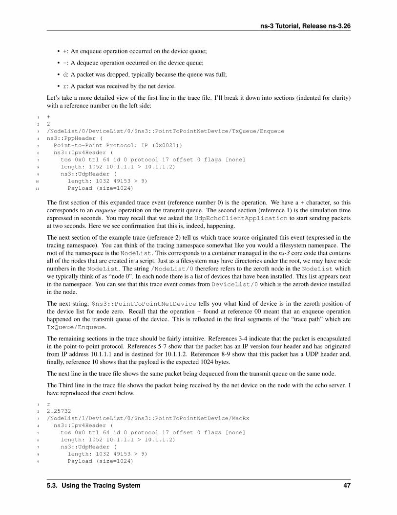
ns-3 Tutorial, Release ns-3.26
• +: An enqueue operation occurred on the device queue;
• -: A dequeue operation occurred on the device queue;
• d: A packet was dropped, typically because the queue was full;
• r: A packet was received by the net device.
Let’s take a more detailed view of the first line in the trace file. I’ll break it down into sections (indented for clarity)with a reference number on the left side:
1 +2 23 /NodeList/0/DeviceList/0/$ns3::PointToPointNetDevice/TxQueue/Enqueue4 ns3::PppHeader (5 Point-to-Point Protocol: IP (0x0021))6 ns3::Ipv4Header (7 tos 0x0 ttl 64 id 0 protocol 17 offset 0 flags [none]8 length: 1052 10.1.1.1 > 10.1.1.2)9 ns3::UdpHeader (
10 length: 1032 49153 > 9)11 Payload (size=1024)
The first section of this expanded trace event (reference number 0) is the operation. We have a + character, so thiscorresponds to an enqueue operation on the transmit queue. The second section (reference 1) is the simulation timeexpressed in seconds. You may recall that we asked the UdpEchoClientApplication to start sending packetsat two seconds. Here we see confirmation that this is, indeed, happening.
The next section of the example trace (reference 2) tell us which trace source originated this event (expressed in thetracing namespace). You can think of the tracing namespace somewhat like you would a filesystem namespace. Theroot of the namespace is the NodeList. This corresponds to a container managed in the ns-3 core code that containsall of the nodes that are created in a script. Just as a filesystem may have directories under the root, we may have nodenumbers in the NodeList. The string /NodeList/0 therefore refers to the zeroth node in the NodeList whichwe typically think of as “node 0”. In each node there is a list of devices that have been installed. This list appears nextin the namespace. You can see that this trace event comes from DeviceList/0 which is the zeroth device installedin the node.
The next string, $ns3::PointToPointNetDevice tells you what kind of device is in the zeroth position ofthe device list for node zero. Recall that the operation + found at reference 00 meant that an enqueue operationhappened on the transmit queue of the device. This is reflected in the final segments of the “trace path” which areTxQueue/Enqueue.
The remaining sections in the trace should be fairly intuitive. References 3-4 indicate that the packet is encapsulatedin the point-to-point protocol. References 5-7 show that the packet has an IP version four header and has originatedfrom IP address 10.1.1.1 and is destined for 10.1.1.2. References 8-9 show that this packet has a UDP header and,finally, reference 10 shows that the payload is the expected 1024 bytes.
The next line in the trace file shows the same packet being dequeued from the transmit queue on the same node.
The Third line in the trace file shows the packet being received by the net device on the node with the echo server. Ihave reproduced that event below.
1 r2 2.257323 /NodeList/1/DeviceList/0/$ns3::PointToPointNetDevice/MacRx4 ns3::Ipv4Header (5 tos 0x0 ttl 64 id 0 protocol 17 offset 0 flags [none]6 length: 1052 10.1.1.1 > 10.1.1.2)7 ns3::UdpHeader (8 length: 1032 49153 > 9)9 Payload (size=1024)
5.3. Using the Tracing System 47
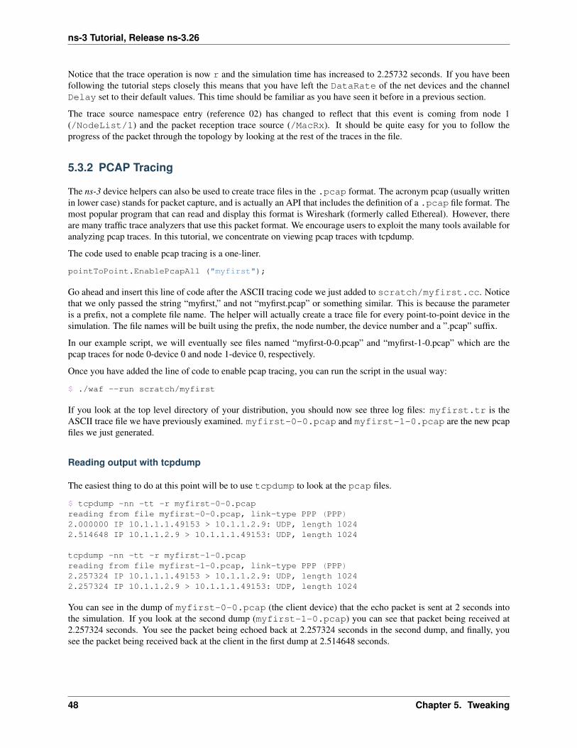
ns-3 Tutorial, Release ns-3.26
Notice that the trace operation is now r and the simulation time has increased to 2.25732 seconds. If you have beenfollowing the tutorial steps closely this means that you have left the DataRate of the net devices and the channelDelay set to their default values. This time should be familiar as you have seen it before in a previous section.
The trace source namespace entry (reference 02) has changed to reflect that this event is coming from node 1(/NodeList/1) and the packet reception trace source (/MacRx). It should be quite easy for you to follow theprogress of the packet through the topology by looking at the rest of the traces in the file.
5.3.2 PCAP Tracing
The ns-3 device helpers can also be used to create trace files in the .pcap format. The acronym pcap (usually writtenin lower case) stands for packet capture, and is actually an API that includes the definition of a .pcap file format. Themost popular program that can read and display this format is Wireshark (formerly called Ethereal). However, thereare many traffic trace analyzers that use this packet format. We encourage users to exploit the many tools available foranalyzing pcap traces. In this tutorial, we concentrate on viewing pcap traces with tcpdump.
The code used to enable pcap tracing is a one-liner.
pointToPoint.EnablePcapAll ("myfirst");
Go ahead and insert this line of code after the ASCII tracing code we just added to scratch/myfirst.cc. Noticethat we only passed the string “myfirst,” and not “myfirst.pcap” or something similar. This is because the parameteris a prefix, not a complete file name. The helper will actually create a trace file for every point-to-point device in thesimulation. The file names will be built using the prefix, the node number, the device number and a ”.pcap” suffix.
In our example script, we will eventually see files named “myfirst-0-0.pcap” and “myfirst-1-0.pcap” which are thepcap traces for node 0-device 0 and node 1-device 0, respectively.
Once you have added the line of code to enable pcap tracing, you can run the script in the usual way:
$ ./waf --run scratch/myfirst
If you look at the top level directory of your distribution, you should now see three log files: myfirst.tr is theASCII trace file we have previously examined. myfirst-0-0.pcap and myfirst-1-0.pcap are the new pcapfiles we just generated.
Reading output with tcpdump
The easiest thing to do at this point will be to use tcpdump to look at the pcap files.
$ tcpdump -nn -tt -r myfirst-0-0.pcapreading from file myfirst-0-0.pcap, link-type PPP (PPP)2.000000 IP 10.1.1.1.49153 > 10.1.1.2.9: UDP, length 10242.514648 IP 10.1.1.2.9 > 10.1.1.1.49153: UDP, length 1024
tcpdump -nn -tt -r myfirst-1-0.pcapreading from file myfirst-1-0.pcap, link-type PPP (PPP)2.257324 IP 10.1.1.1.49153 > 10.1.1.2.9: UDP, length 10242.257324 IP 10.1.1.2.9 > 10.1.1.1.49153: UDP, length 1024
You can see in the dump of myfirst-0-0.pcap (the client device) that the echo packet is sent at 2 seconds intothe simulation. If you look at the second dump (myfirst-1-0.pcap) you can see that packet being received at2.257324 seconds. You see the packet being echoed back at 2.257324 seconds in the second dump, and finally, yousee the packet being received back at the client in the first dump at 2.514648 seconds.
48 Chapter 5. Tweaking

ns-3 Tutorial, Release ns-3.26
Reading output with Wireshark
If you are unfamiliar with Wireshark, there is a web site available from which you can download programs anddocumentation: http://www.wireshark.org/.
Wireshark is a graphical user interface which can be used for displaying these trace files. If you have Wiresharkavailable, you can open each of the trace files and display the contents as if you had captured the packets using apacket sniffer.
5.3. Using the Tracing System 49

ns-3 Tutorial, Release ns-3.26
50 Chapter 5. Tweaking

CHAPTER
SIX
BUILDING TOPOLOGIES
6.1 Building a Bus Network Topology
In this section we are going to expand our mastery of ns-3 network devices and channels to cover an example of a busnetwork. ns-3 provides a net device and channel we call CSMA (Carrier Sense Multiple Access).
The ns-3 CSMA device models a simple network in the spirit of Ethernet. A real Ethernet uses CSMA/CD (CarrierSense Multiple Access with Collision Detection) scheme with exponentially increasing backoff to contend for theshared transmission medium. The ns-3 CSMA device and channel models only a subset of this.
Just as we have seen point-to-point topology helper objects when constructing point-to-point topologies, we will seeequivalent CSMA topology helpers in this section. The appearance and operation of these helpers should look quitefamiliar to you.
We provide an example script in our examples/tutorial directory. This script builds on the first.ccscript and adds a CSMA network to the point-to-point simulation we’ve already considered. Go ahead and openexamples/tutorial/second.cc in your favorite editor. You will have already seen enough ns-3 code to un-derstand most of what is going on in this example, but we will go over the entire script and examine some of theoutput.
Just as in the first.cc example (and in all ns-3 examples) the file begins with an emacs mode line and some GPLboilerplate.
The actual code begins by loading module include files just as was done in the first.cc example.
#include "ns3/core-module.h"#include "ns3/network-module.h"#include "ns3/csma-module.h"#include "ns3/internet-module.h"#include "ns3/point-to-point-module.h"#include "ns3/applications-module.h"#include "ns3/ipv4-global-routing-helper.h"
One thing that can be surprisingly useful is a small bit of ASCII art that shows a cartoon of the network topologyconstructed in the example. You will find a similar “drawing” in most of our examples.
In this case, you can see that we are going to extend our point-to-point example (the link between the nodes n0 andn1 below) by hanging a bus network off of the right side. Notice that this is the default network topology since youcan actually vary the number of nodes created on the LAN. If you set nCsma to one, there will be a total of two nodeson the LAN (CSMA channel) — one required node and one “extra” node. By default there are three “extra” nodes asseen below:
// Default Network Topology//// 10.1.1.0// n0 -------------- n1 n2 n3 n4
51

ns-3 Tutorial, Release ns-3.26
// point-to-point | | | |// ================// LAN 10.1.2.0
Then the ns-3 namespace is used and a logging component is defined. This is all just as it was in first.cc, sothere is nothing new yet.
using namespace ns3;
NS_LOG_COMPONENT_DEFINE ("SecondScriptExample");
The main program begins with a slightly different twist. We use a verbose flag to determine whether or not theUdpEchoClientApplication and UdpEchoServerApplication logging components are enabled. Thisflag defaults to true (the logging components are enabled) but allows us to turn off logging during regression testingof this example.
You will see some familiar code that will allow you to change the number of devices on the CSMA network viacommand line argument. We did something similar when we allowed the number of packets sent to be changed in thesection on command line arguments. The last line makes sure you have at least one “extra” node.
The code consists of variations of previously covered API so you should be entirely comfortable with the followingcode at this point in the tutorial.
bool verbose = true;uint32_t nCsma = 3;
CommandLine cmd;cmd.AddValue ("nCsma", "Number of \"extra\" CSMA nodes/devices", nCsma);cmd.AddValue ("verbose", "Tell echo applications to log if true", verbose);
cmd.Parse (argc, argv);
if (verbose){LogComponentEnable("UdpEchoClientApplication", LOG_LEVEL_INFO);LogComponentEnable("UdpEchoServerApplication", LOG_LEVEL_INFO);
}
nCsma = nCsma == 0 ? 1 : nCsma;
The next step is to create two nodes that we will connect via the point-to-point link. The NodeContainer is usedto do this just as was done in first.cc.
NodeContainer p2pNodes;p2pNodes.Create (2);
Next, we declare another NodeContainer to hold the nodes that will be part of the bus (CSMA) network. First, wejust instantiate the container object itself.
NodeContainer csmaNodes;csmaNodes.Add (p2pNodes.Get (1));csmaNodes.Create (nCsma);
The next line of code Gets the first node (as in having an index of one) from the point-to-point node container andadds it to the container of nodes that will get CSMA devices. The node in question is going to end up with a point-to-point device and a CSMA device. We then create a number of “extra” nodes that compose the remainder of theCSMA network. Since we already have one node in the CSMA network – the one that will have both a point-to-pointand CSMA net device, the number of “extra” nodes means the number nodes you desire in the CSMA section minusone.
52 Chapter 6. Building Topologies

ns-3 Tutorial, Release ns-3.26
The next bit of code should be quite familiar by now. We instantiate a PointToPointHelper and set the associateddefault Attributes so that we create a five megabit per second transmitter on devices created using the helper anda two millisecond delay on channels created by the helper.
PointToPointHelper pointToPoint;pointToPoint.SetDeviceAttribute ("DataRate", StringValue ("5Mbps"));pointToPoint.SetChannelAttribute ("Delay", StringValue ("2ms"));
NetDeviceContainer p2pDevices;p2pDevices = pointToPoint.Install (p2pNodes);
We then instantiate a NetDeviceContainer to keep track of the point-to-point net devices and we Installdevices on the point-to-point nodes.
We mentioned above that you were going to see a helper for CSMA devices and channels, and the next lines introducethem. The CsmaHelper works just like a PointToPointHelper, but it creates and connects CSMA devicesand channels. In the case of a CSMA device and channel pair, notice that the data rate is specified by a channelAttribute instead of a device Attribute. This is because a real CSMA network does not allow one to mix, forexample, 10Base-T and 100Base-T devices on a given channel. We first set the data rate to 100 megabits per second,and then set the speed-of-light delay of the channel to 6560 nano-seconds (arbitrarily chosen as 1 nanosecond per footover a 100 meter segment). Notice that you can set an Attribute using its native data type.
CsmaHelper csma;csma.SetChannelAttribute ("DataRate", StringValue ("100Mbps"));csma.SetChannelAttribute ("Delay", TimeValue (NanoSeconds (6560)));
NetDeviceContainer csmaDevices;csmaDevices = csma.Install (csmaNodes);
Just as we created a NetDeviceContainer to hold the devices created by the PointToPointHelperwe createa NetDeviceContainer to hold the devices created by our CsmaHelper. We call the Install method of theCsmaHelper to install the devices into the nodes of the csmaNodes NodeContainer.
We now have our nodes, devices and channels created, but we have no protocol stacks present. Just as in thefirst.cc script, we will use the InternetStackHelper to install these stacks.
InternetStackHelper stack;stack.Install (p2pNodes.Get (0));stack.Install (csmaNodes);
Recall that we took one of the nodes from the p2pNodes container and added it to the csmaNodes container. Thuswe only need to install the stacks on the remaining p2pNodes node, and all of the nodes in the csmaNodes containerto cover all of the nodes in the simulation.
Just as in the first.cc example script, we are going to use the Ipv4AddressHelper to assign IP addresses toour device interfaces. First we use the network 10.1.1.0 to create the two addresses needed for our two point-to-pointdevices.
Ipv4AddressHelper address;address.SetBase ("10.1.1.0", "255.255.255.0");Ipv4InterfaceContainer p2pInterfaces;p2pInterfaces = address.Assign (p2pDevices);
Recall that we save the created interfaces in a container to make it easy to pull out addressing information later for usein setting up the applications.
We now need to assign IP addresses to our CSMA device interfaces. The operation works just as it did for the point-to-point case, except we now are performing the operation on a container that has a variable number of CSMA devices— remember we made the number of CSMA devices changeable by command line argument. The CSMA deviceswill be associated with IP addresses from network number 10.1.2.0 in this case, as seen below.
6.1. Building a Bus Network Topology 53

ns-3 Tutorial, Release ns-3.26
address.SetBase ("10.1.2.0", "255.255.255.0");Ipv4InterfaceContainer csmaInterfaces;csmaInterfaces = address.Assign (csmaDevices);
Now we have a topology built, but we need applications. This section is going to be fundamentally similar to theapplications section of first.cc but we are going to instantiate the server on one of the nodes that has a CSMAdevice and the client on the node having only a point-to-point device.
First, we set up the echo server. We create a UdpEchoServerHelper and provide a required Attribute value tothe constructor which is the server port number. Recall that this port can be changed later using the SetAttributemethod if desired, but we require it to be provided to the constructor.
UdpEchoServerHelper echoServer (9);
ApplicationContainer serverApps = echoServer.Install (csmaNodes.Get (nCsma));serverApps.Start (Seconds (1.0));serverApps.Stop (Seconds (10.0));
Recall that the csmaNodes NodeContainer contains one of the nodes created for the point-to-point network andnCsma “extra” nodes. What we want to get at is the last of the “extra” nodes. The zeroth entry of the csmaNodescontainer will be the point-to-point node. The easy way to think of this, then, is if we create one “extra” CSMA node,then it will be at index one of the csmaNodes container. By induction, if we create nCsma “extra” nodes the lastone will be at index nCsma. You see this exhibited in the Get of the first line of code.
The client application is set up exactly as we did in the first.cc example script. Again, we provide requiredAttributes to the UdpEchoClientHelper in the constructor (in this case the remote address and port). Wetell the client to send packets to the server we just installed on the last of the “extra” CSMA nodes. We install theclient on the leftmost point-to-point node seen in the topology illustration.
UdpEchoClientHelper echoClient (csmaInterfaces.GetAddress (nCsma), 9);echoClient.SetAttribute ("MaxPackets", UintegerValue (1));echoClient.SetAttribute ("Interval", TimeValue (Seconds (1.0)));echoClient.SetAttribute ("PacketSize", UintegerValue (1024));
ApplicationContainer clientApps = echoClient.Install (p2pNodes.Get (0));clientApps.Start (Seconds (2.0));clientApps.Stop (Seconds (10.0));
Since we have actually built an internetwork here, we need some form of internetwork routing. ns-3 provides what wecall global routing to help you out. Global routing takes advantage of the fact that the entire internetwork is accessiblein the simulation and runs through the all of the nodes created for the simulation — it does the hard work of setting uprouting for you without having to configure routers.
Basically, what happens is that each node behaves as if it were an OSPF router that communicates instantly andmagically with all other routers behind the scenes. Each node generates link advertisements and communicates themdirectly to a global route manager which uses this global information to construct the routing tables for each node.Setting up this form of routing is a one-liner:
Ipv4GlobalRoutingHelper::PopulateRoutingTables ();
Next we enable pcap tracing. The first line of code to enable pcap tracing in the point-to-point helper should be familiarto you by now. The second line enables pcap tracing in the CSMA helper and there is an extra parameter you haven’tencountered yet.
pointToPoint.EnablePcapAll ("second");csma.EnablePcap ("second", csmaDevices.Get (1), true);
The CSMA network is a multi-point-to-point network. This means that there can (and are in this case) multipleendpoints on a shared medium. Each of these endpoints has a net device associated with it. There are two basic
54 Chapter 6. Building Topologies

ns-3 Tutorial, Release ns-3.26
alternatives to gathering trace information from such a network. One way is to create a trace file for each net deviceand store only the packets that are emitted or consumed by that net device. Another way is to pick one of the devicesand place it in promiscuous mode. That single device then “sniffs” the network for all packets and stores them in asingle pcap file. This is how tcpdump, for example, works. That final parameter tells the CSMA helper whether ornot to arrange to capture packets in promiscuous mode.
In this example, we are going to select one of the devices on the CSMA network and ask it to perform a promiscuoussniff of the network, thereby emulating what tcpdumpwould do. If you were on a Linux machine you might do some-thing like tcpdump -i eth0 to get the trace. In this case, we specify the device using csmaDevices.Get(1),which selects the first device in the container. Setting the final parameter to true enables promiscuous captures.
The last section of code just runs and cleans up the simulation just like the first.cc example.
Simulator::Run ();Simulator::Destroy ();return 0;
}
In order to run this example, copy the second.cc example script into the scratch directory and use waf to build justas you did with the first.cc example. If you are in the top-level directory of the repository you just type,
$ cp examples/tutorial/second.cc scratch/mysecond.cc$ ./waf
Warning: We use the file second.cc as one of our regression tests to verify that it works exactly as we think it shouldin order to make your tutorial experience a positive one. This means that an executable named second already existsin the project. To avoid any confusion about what you are executing, please do the renaming to mysecond.ccsuggested above.
If you are following the tutorial religiously (you are, aren’t you) you will still have the NS_LOG variable set, so goahead and clear that variable and run the program.
$ export NS_LOG=$ ./waf --run scratch/mysecond
Since we have set up the UDP echo applications to log just as we did in first.cc, you will see similar output whenyou run the script.
Waf: Entering directory `/home/craigdo/repos/ns-3-allinone/ns-3-dev/build'Waf: Leaving directory `/home/craigdo/repos/ns-3-allinone/ns-3-dev/build''build' finished successfully (0.415s)Sent 1024 bytes to 10.1.2.4Received 1024 bytes from 10.1.1.1Received 1024 bytes from 10.1.2.4
Recall that the first message, “Sent 1024 bytes to 10.1.2.4,” is the UDP echo client sending a packet tothe server. In this case, the server is on a different network (10.1.2.0). The second message, “Received 1024bytes from 10.1.1.1,” is from the UDP echo server, generated when it receives the echo packet. The finalmessage, “Received 1024 bytes from 10.1.2.4,” is from the echo client, indicating that it has receivedits echo back from the server.
If you now go and look in the top level directory, you will find three trace files:
second-0-0.pcap second-1-0.pcap second-2-0.pcap
Let’s take a moment to look at the naming of these files. They all have the same form,<name>-<node>-<device>.pcap. For example, the first file in the listing is second-0-0.pcapwhich is the pcap trace from node zero, device zero. This is the point-to-point net device on node zero. The filesecond-1-0.pcap is the pcap trace for device zero on node one, also a point-to-point net device; and the filesecond-2-0.pcap is the pcap trace for device zero on node two.
6.1. Building a Bus Network Topology 55

ns-3 Tutorial, Release ns-3.26
If you refer back to the topology illustration at the start of the section, you will see that node zero is the leftmost nodeof the point-to-point link and node one is the node that has both a point-to-point device and a CSMA device. Youwill see that node two is the first “extra” node on the CSMA network and its device zero was selected as the device tocapture the promiscuous-mode trace.
Now, let’s follow the echo packet through the internetwork. First, do a tcpdump of the trace file for the leftmostpoint-to-point node — node zero.
$ tcpdump -nn -tt -r second-0-0.pcap
You should see the contents of the pcap file displayed:
reading from file second-0-0.pcap, link-type PPP (PPP)2.000000 IP 10.1.1.1.49153 > 10.1.2.4.9: UDP, length 10242.017607 IP 10.1.2.4.9 > 10.1.1.1.49153: UDP, length 1024
The first line of the dump indicates that the link type is PPP (point-to-point) which we expect. You then see theecho packet leaving node zero via the device associated with IP address 10.1.1.1 headed for IP address 10.1.2.4 (therightmost CSMA node). This packet will move over the point-to-point link and be received by the point-to-point netdevice on node one. Let’s take a look:
$ tcpdump -nn -tt -r second-1-0.pcap
You should now see the pcap trace output of the other side of the point-to-point link:
reading from file second-1-0.pcap, link-type PPP (PPP)2.003686 IP 10.1.1.1.49153 > 10.1.2.4.9: UDP, length 10242.013921 IP 10.1.2.4.9 > 10.1.1.1.49153: UDP, length 1024
Here we see that the link type is also PPP as we would expect. You see the packet from IP address 10.1.1.1 (that wassent at 2.000000 seconds) headed toward IP address 10.1.2.4 appear on this interface. Now, internally to this node, thepacket will be forwarded to the CSMA interface and we should see it pop out on that device headed for its ultimatedestination.
Remember that we selected node 2 as the promiscuous sniffer node for the CSMA network so let’s then look atsecond-2-0.pcap and see if its there.
$ tcpdump -nn -tt -r second-2-0.pcap
You should now see the promiscuous dump of node two, device zero:
reading from file second-2-0.pcap, link-type EN10MB (Ethernet)2.007698 ARP, Request who-has 10.1.2.4 (ff:ff:ff:ff:ff:ff) tell 10.1.2.1, length 502.007710 ARP, Reply 10.1.2.4 is-at 00:00:00:00:00:06, length 502.007803 IP 10.1.1.1.49153 > 10.1.2.4.9: UDP, length 10242.013815 ARP, Request who-has 10.1.2.1 (ff:ff:ff:ff:ff:ff) tell 10.1.2.4, length 502.013828 ARP, Reply 10.1.2.1 is-at 00:00:00:00:00:03, length 502.013921 IP 10.1.2.4.9 > 10.1.1.1.49153: UDP, length 1024
As you can see, the link type is now “Ethernet”. Something new has appeared, though. The bus network needs ARP, theAddress Resolution Protocol. Node one knows it needs to send the packet to IP address 10.1.2.4, but it doesn’t knowthe MAC address of the corresponding node. It broadcasts on the CSMA network (ff:ff:ff:ff:ff:ff) asking for the devicethat has IP address 10.1.2.4. In this case, the rightmost node replies saying it is at MAC address 00:00:00:00:00:06.Note that node two is not directly involved in this exchange, but is sniffing the network and reporting all of the trafficit sees.
This exchange is seen in the following lines,
2.007698 ARP, Request who-has 10.1.2.4 (ff:ff:ff:ff:ff:ff) tell 10.1.2.1, length 502.007710 ARP, Reply 10.1.2.4 is-at 00:00:00:00:00:06, length 50
56 Chapter 6. Building Topologies

ns-3 Tutorial, Release ns-3.26
Then node one, device one goes ahead and sends the echo packet to the UDP echo server at IP address 10.1.2.4.
2.007803 IP 10.1.1.1.49153 > 10.1.2.4.9: UDP, length 1024
The server receives the echo request and turns the packet around trying to send it back to the source. The server knowsthat this address is on another network that it reaches via IP address 10.1.2.1. This is because we initialized globalrouting and it has figured all of this out for us. But, the echo server node doesn’t know the MAC address of the firstCSMA node, so it has to ARP for it just like the first CSMA node had to do.
2.013815 ARP, Request who-has 10.1.2.1 (ff:ff:ff:ff:ff:ff) tell 10.1.2.4, length 502.013828 ARP, Reply 10.1.2.1 is-at 00:00:00:00:00:03, length 50
The server then sends the echo back to the forwarding node.
2.013921 IP 10.1.2.4.9 > 10.1.1.1.49153: UDP, length 1024
Looking back at the rightmost node of the point-to-point link,
$ tcpdump -nn -tt -r second-1-0.pcap
You can now see the echoed packet coming back onto the point-to-point link as the last line of the trace dump.
reading from file second-1-0.pcap, link-type PPP (PPP)2.003686 IP 10.1.1.1.49153 > 10.1.2.4.9: UDP, length 10242.013921 IP 10.1.2.4.9 > 10.1.1.1.49153: UDP, length 1024
Lastly, you can look back at the node that originated the echo
$ tcpdump -nn -tt -r second-0-0.pcap
and see that the echoed packet arrives back at the source at 2.017607 seconds,
reading from file second-0-0.pcap, link-type PPP (PPP)2.000000 IP 10.1.1.1.49153 > 10.1.2.4.9: UDP, length 10242.017607 IP 10.1.2.4.9 > 10.1.1.1.49153: UDP, length 1024
Finally, recall that we added the ability to control the number of CSMA devices in the simulation by command lineargument. You can change this argument in the same way as when we looked at changing the number of packetsechoed in the first.cc example. Try running the program with the number of “extra” devices set to four:
$ ./waf --run "scratch/mysecond --nCsma=4"
You should now see,
Waf: Entering directory `/home/craigdo/repos/ns-3-allinone/ns-3-dev/build'Waf: Leaving directory `/home/craigdo/repos/ns-3-allinone/ns-3-dev/build''build' finished successfully (0.405s)At time 2s client sent 1024 bytes to 10.1.2.5 port 9At time 2.0118s server received 1024 bytes from 10.1.1.1 port 49153At time 2.0118s server sent 1024 bytes to 10.1.1.1 port 49153At time 2.02461s client received 1024 bytes from 10.1.2.5 port 9
Notice that the echo server has now been relocated to the last of the CSMA nodes, which is 10.1.2.5 instead of thedefault case, 10.1.2.4.
It is possible that you may not be satisfied with a trace file generated by a bystander in the CSMA network. You mayreally want to get a trace from a single device and you may not be interested in any other traffic on the network. Youcan do this fairly easily.
Let’s take a look at scratch/mysecond.cc and add that code enabling us to be more specific. ns-3 helpersprovide methods that take a node number and device number as parameters. Go ahead and replace the EnablePcapcalls with the calls below.
6.1. Building a Bus Network Topology 57

ns-3 Tutorial, Release ns-3.26
pointToPoint.EnablePcap ("second", p2pNodes.Get (0)->GetId (), 0);csma.EnablePcap ("second", csmaNodes.Get (nCsma)->GetId (), 0, false);csma.EnablePcap ("second", csmaNodes.Get (nCsma-1)->GetId (), 0, false);
We know that we want to create a pcap file with the base name “second” and we also know that the device of interestin both cases is going to be zero, so those parameters are not really interesting.
In order to get the node number, you have two choices: first, nodes are numbered in a monotonically increasing fashionstarting from zero in the order in which you created them. One way to get a node number is to figure this number out“manually” by contemplating the order of node creation. If you take a look at the network topology illustration at thebeginning of the file, we did this for you and you can see that the last CSMA node is going to be node number nCsma+ 1. This approach can become annoyingly difficult in larger simulations.
An alternate way, which we use here, is to realize that the NodeContainers contain pointers to ns-3 Node Objects.The Node Object has a method called GetId which will return that node’s ID, which is the node number we seek.Let’s go take a look at the Doxygen for the Node and locate that method, which is further down in the ns-3 core codethan we’ve seen so far; but sometimes you have to search diligently for useful things.
Go to the Doxygen documentation for your release (recall that you can find it on the project web site). You can get tothe Node documentation by looking through at the “Classes” tab and scrolling down the “Class List” until you findns3::Node. Select ns3::Node and you will be taken to the documentation for the Node class. If you now scrolldown to the GetId method and select it, you will be taken to the detailed documentation for the method. Using theGetId method can make determining node numbers much easier in complex topologies.
Let’s clear the old trace files out of the top-level directory to avoid confusion about what is going on,
$ rm *.pcap$ rm *.tr
If you build the new script and run the simulation setting nCsma to 100,
$ ./waf --run "scratch/mysecond --nCsma=100"
you will see the following output:
Waf: Entering directory `/home/craigdo/repos/ns-3-allinone/ns-3-dev/build'Waf: Leaving directory `/home/craigdo/repos/ns-3-allinone/ns-3-dev/build''build' finished successfully (0.407s)At time 2s client sent 1024 bytes to 10.1.2.101 port 9At time 2.0068s server received 1024 bytes from 10.1.1.1 port 49153At time 2.0068s server sent 1024 bytes to 10.1.1.1 port 49153At time 2.01761s client received 1024 bytes from 10.1.2.101 port 9
Note that the echo server is now located at 10.1.2.101 which corresponds to having 100 “extra” CSMA nodes with theecho server on the last one. If you list the pcap files in the top level directory you will see,
second-0-0.pcap second-100-0.pcap second-101-0.pcap
The trace file second-0-0.pcap is the “leftmost” point-to-point device which is the echo packet source. The filesecond-101-0.pcap corresponds to the rightmost CSMA device which is where the echo server resides. Youmay have noticed that the final parameter on the call to enable pcap tracing on the echo server node was false. Thismeans that the trace gathered on that node was in non-promiscuous mode.
To illustrate the difference between promiscuous and non-promiscuous traces, we also requested a non-promiscuoustrace for the next-to-last node. Go ahead and take a look at the tcpdump for second-100-0.pcap.
$ tcpdump -nn -tt -r second-100-0.pcap
You can now see that node 100 is really a bystander in the echo exchange. The only packets that it receives are theARP requests which are broadcast to the entire CSMA network.
58 Chapter 6. Building Topologies

ns-3 Tutorial, Release ns-3.26
reading from file second-100-0.pcap, link-type EN10MB (Ethernet)2.006698 ARP, Request who-has 10.1.2.101 (ff:ff:ff:ff:ff:ff) tell 10.1.2.1, length 502.013815 ARP, Request who-has 10.1.2.1 (ff:ff:ff:ff:ff:ff) tell 10.1.2.101, length 50
Now take a look at the tcpdump for second-101-0.pcap.
$ tcpdump -nn -tt -r second-101-0.pcap
You can now see that node 101 is really the participant in the echo exchange.
reading from file second-101-0.pcap, link-type EN10MB (Ethernet)2.006698 ARP, Request who-has 10.1.2.101 (ff:ff:ff:ff:ff:ff) tell 10.1.2.1, length 502.006698 ARP, Reply 10.1.2.101 is-at 00:00:00:00:00:67, length 502.006803 IP 10.1.1.1.49153 > 10.1.2.101.9: UDP, length 10242.013803 ARP, Request who-has 10.1.2.1 (ff:ff:ff:ff:ff:ff) tell 10.1.2.101, length 502.013828 ARP, Reply 10.1.2.1 is-at 00:00:00:00:00:03, length 502.013828 IP 10.1.2.101.9 > 10.1.1.1.49153: UDP, length 1024
6.2 Models, Attributes and Reality
This is a convenient place to make a small excursion and make an important point. It may or may not be obvious toyou, but whenever one is using a simulation, it is important to understand exactly what is being modeled and what isnot. It is tempting, for example, to think of the CSMA devices and channels used in the previous section as if theywere real Ethernet devices; and to expect a simulation result to directly reflect what will happen in a real Ethernet.This is not the case.
A model is, by definition, an abstraction of reality. It is ultimately the responsibility of the simulation script author todetermine the so-called “range of accuracy” and “domain of applicability” of the simulation as a whole, and thereforeits constituent parts.
In some cases, like Csma, it can be fairly easy to determine what is not modeled. By reading the model description(csma.h) you can find that there is no collision detection in the CSMA model and decide on how applicable its usewill be in your simulation or what caveats you may want to include with your results. In other cases, it can be quiteeasy to configure behaviors that might not agree with any reality you can go out and buy. It will prove worthwhile tospend some time investigating a few such instances, and how easily you can swerve outside the bounds of reality inyour simulations.
As you have seen, ns-3 provides Attributes which a user can easily set to change model behavior. Consider twoof the Attributes of the CsmaNetDevice: Mtu and EncapsulationMode. The Mtu attribute indicates theMaximum Transmission Unit to the device. This is the size of the largest Protocol Data Unit (PDU) that the devicecan send.
The MTU defaults to 1500 bytes in the CsmaNetDevice. This default corresponds to a number found in RFC 894,“A Standard for the Transmission of IP Datagrams over Ethernet Networks.” The number is actually derived from themaximum packet size for 10Base5 (full-spec Ethernet) networks – 1518 bytes. If you subtract the DIX encapsulationoverhead for Ethernet packets (18 bytes) you will end up with a maximum possible data size (MTU) of 1500 bytes.One can also find that the MTU for IEEE 802.3 networks is 1492 bytes. This is because LLC/SNAP encapsulation addsan extra eight bytes of overhead to the packet. In both cases, the underlying hardware can only send 1518 bytes, butthe data size is different.
In order to set the encapsulation mode, the CsmaNetDevice provides an Attribute calledEncapsulationMode which can take on the values Dix or Llc. These correspond to Ethernet and LLC/SNAPframing respectively.
If one leaves the Mtu at 1500 bytes and changes the encapsulation mode to Llc, the result will be a network thatencapsulates 1500 byte PDUs with LLC/SNAP framing resulting in packets of 1526 bytes, which would be illegal
6.2. Models, Attributes and Reality 59

ns-3 Tutorial, Release ns-3.26
in many networks, since they can transmit a maximum of 1518 bytes per packet. This would most likely result in asimulation that quite subtly does not reflect the reality you might be expecting.
Just to complicate the picture, there exist jumbo frames (1500 < MTU <= 9000 bytes) and super-jumbo (MTU > 9000bytes) frames that are not officially sanctioned by IEEE but are available in some high-speed (Gigabit) networks andNICs. One could leave the encapsulation mode set to Dix, and set the Mtu Attribute on a CsmaNetDeviceto 64000 bytes – even though an associated CsmaChannel DataRate was set at 10 megabits per second. Thiswould essentially model an Ethernet switch made out of vampire-tapped 1980s-style 10Base5 networks that supportsuper-jumbo datagrams. This is certainly not something that was ever made, nor is likely to ever be made, but it isquite easy for you to configure.
In the previous example, you used the command line to create a simulation that had 100 Csma nodes. You could havejust as easily created a simulation with 500 nodes. If you were actually modeling that 10Base5 vampire-tap network,the maximum length of a full-spec Ethernet cable is 500 meters, with a minimum tap spacing of 2.5 meters. Thatmeans there could only be 200 taps on a real network. You could have quite easily built an illegal network in that wayas well. This may or may not result in a meaningful simulation depending on what you are trying to model.
Similar situations can occur in many places in ns-3 and in any simulator. For example, you may be able to positionnodes in such a way that they occupy the same space at the same time, or you may be able to configure amplifiers ornoise levels that violate the basic laws of physics.
ns-3 generally favors flexibility, and many models will allow freely setting Attributes without trying to enforceany arbitrary consistency or particular underlying spec.
The thing to take home from this is that ns-3 is going to provide a super-flexible base for you to experiment with. Itis up to you to understand what you are asking the system to do and to make sure that the simulations you create havesome meaning and some connection with a reality defined by you.
6.3 Building a Wireless Network Topology
In this section we are going to further expand our knowledge of ns-3 network devices and channels to cover anexample of a wireless network. ns-3 provides a set of 802.11 models that attempt to provide an accurate MAC-levelimplementation of the 802.11 specification and a “not-so-slow” PHY-level model of the 802.11a specification.
Just as we have seen both point-to-point and CSMA topology helper objects when constructing point-to-point topolo-gies, we will see equivalent Wifi topology helpers in this section. The appearance and operation of these helpersshould look quite familiar to you.
We provide an example script in our examples/tutorial directory. This script builds on the second.cc scriptand adds a Wifi network. Go ahead and open examples/tutorial/third.cc in your favorite editor. You willhave already seen enough ns-3 code to understand most of what is going on in this example, but there are a few newthings, so we will go over the entire script and examine some of the output.
Just as in the second.cc example (and in all ns-3 examples) the file begins with an emacs mode line and some GPLboilerplate.
Take a look at the ASCII art (reproduced below) that shows the default network topology constructed in the example.You can see that we are going to further extend our example by hanging a wireless network off of the left side. Noticethat this is a default network topology since you can actually vary the number of nodes created on the wired andwireless networks. Just as in the second.cc script case, if you change nCsma, it will give you a number of “extra”CSMA nodes. Similarly, you can set nWifi to control how many STA (station) nodes are created in the simulation.There will always be one AP (access point) node on the wireless network. By default there are three “extra” CSMAnodes and three wireless STA nodes.
The code begins by loading module include files just as was done in the second.cc example. There are a couple ofnew includes corresponding to the Wifi module and the mobility module which we will discuss below.
60 Chapter 6. Building Topologies

ns-3 Tutorial, Release ns-3.26
#include "ns3/core-module.h"#include "ns3/point-to-point-module.h"#include "ns3/network-module.h"#include "ns3/applications-module.h"#include "ns3/wifi-module.h"#include "ns3/mobility-module.h"#include "ns3/csma-module.h"#include "ns3/internet-module.h"
The network topology illustration follows:
// Default Network Topology//// Wifi 10.1.3.0// AP// * * * *// | | | | 10.1.1.0// n5 n6 n7 n0 -------------- n1 n2 n3 n4// point-to-point | | | |// ================// LAN 10.1.2.0
You can see that we are adding a new network device to the node on the left side of the point-to-point link that becomesthe access point for the wireless network. A number of wireless STA nodes are created to fill out the new 10.1.3.0network as shown on the left side of the illustration.
After the illustration, the ns-3 namespace is used and a logging component is defined. This should all be quitefamiliar by now.
using namespace ns3;
NS_LOG_COMPONENT_DEFINE ("ThirdScriptExample");
The main program begins just like second.cc by adding some command line parameters for enabling or disablinglogging components and for changing the number of devices created.
bool verbose = true;uint32_t nCsma = 3;uint32_t nWifi = 3;
CommandLine cmd;cmd.AddValue ("nCsma", "Number of \"extra\" CSMA nodes/devices", nCsma);cmd.AddValue ("nWifi", "Number of wifi STA devices", nWifi);cmd.AddValue ("verbose", "Tell echo applications to log if true", verbose);
cmd.Parse (argc,argv);
if (verbose){LogComponentEnable("UdpEchoClientApplication", LOG_LEVEL_INFO);LogComponentEnable("UdpEchoServerApplication", LOG_LEVEL_INFO);
}
Just as in all of the previous examples, the next step is to create two nodes that we will connect via the point-to-pointlink.
NodeContainer p2pNodes;p2pNodes.Create (2);
Next, we see an old friend. We instantiate a PointToPointHelper and set the associated default Attributes
6.3. Building a Wireless Network Topology 61

ns-3 Tutorial, Release ns-3.26
so that we create a five megabit per second transmitter on devices created using the helper and a two millisecond delayon channels created by the helper. We then Install the devices on the nodes and the channel between them.
PointToPointHelper pointToPoint;pointToPoint.SetDeviceAttribute ("DataRate", StringValue ("5Mbps"));pointToPoint.SetChannelAttribute ("Delay", StringValue ("2ms"));
NetDeviceContainer p2pDevices;p2pDevices = pointToPoint.Install (p2pNodes);
Next, we declare another NodeContainer to hold the nodes that will be part of the bus (CSMA) network.
NodeContainer csmaNodes;csmaNodes.Add (p2pNodes.Get (1));csmaNodes.Create (nCsma);
The next line of code Gets the first node (as in having an index of one) from the point-to-point node container andadds it to the container of nodes that will get CSMA devices. The node in question is going to end up with a point-to-point device and a CSMA device. We then create a number of “extra” nodes that compose the remainder of the CSMAnetwork.
We then instantiate a CsmaHelper and set its Attributes as we did in the previous example. We create aNetDeviceContainer to keep track of the created CSMA net devices and then we Install CSMA devices onthe selected nodes.
CsmaHelper csma;csma.SetChannelAttribute ("DataRate", StringValue ("100Mbps"));csma.SetChannelAttribute ("Delay", TimeValue (NanoSeconds (6560)));
NetDeviceContainer csmaDevices;csmaDevices = csma.Install (csmaNodes);
Next, we are going to create the nodes that will be part of the Wifi network. We are going to create a number of“station” nodes as specified by the command line argument, and we are going to use the “leftmost” node of the point-to-point link as the node for the access point.
NodeContainer wifiStaNodes;wifiStaNodes.Create (nWifi);NodeContainer wifiApNode = p2pNodes.Get (0);
The next bit of code constructs the wifi devices and the interconnection channel between these wifi nodes. First, weconfigure the PHY and channel helpers:
YansWifiChannelHelper channel = YansWifiChannelHelper::Default ();YansWifiPhyHelper phy = YansWifiPhyHelper::Default ();
For simplicity, this code uses the default PHY layer configuration and channel models which aredocumented in the API doxygen documentation for the YansWifiChannelHelper::Default andYansWifiPhyHelper::Default methods. Once these objects are created, we create a channel object andassociate it to our PHY layer object manager to make sure that all the PHY layer objects created by theYansWifiPhyHelper share the same underlying channel, that is, they share the same wireless medium and cancommunication and interfere:
phy.SetChannel (channel.Create ());
Once the PHY helper is configured, we can focus on the MAC layer. Here we choose to work with non-Qos MACs sowe use a NqosWifiMacHelper object to set MAC parameters.
62 Chapter 6. Building Topologies

ns-3 Tutorial, Release ns-3.26
WifiHelper wifi = WifiHelper::Default ();wifi.SetRemoteStationManager ("ns3::AarfWifiManager");
NqosWifiMacHelper mac = NqosWifiMacHelper::Default ();
The SetRemoteStationManager method tells the helper the type of rate control algorithm to use. Here, it isasking the helper to use the AARF algorithm — details are, of course, available in Doxygen.
Next, we configure the type of MAC, the SSID of the infrastructure network we want to setup and make sure that ourstations don’t perform active probing:
Ssid ssid = Ssid ("ns-3-ssid");mac.SetType ("ns3::StaWifiMac",
"Ssid", SsidValue (ssid),"ActiveProbing", BooleanValue (false));
This code first creates an 802.11 service set identifier (SSID) object that will be used to set the value of the “Ssid”Attribute of the MAC layer implementation. The particular kind of MAC layer that will be created by the helperis specified by Attribute as being of the “ns3::StaWifiMac” type. The use of NqosWifiMacHelper will ensurethat the “QosSupported” Attribute for created MAC objects is set false. The combination of these two configu-rations means that the MAC instance next created will be a non-QoS non-AP station (STA) in an infrastructure BSS(i.e., a BSS with an AP). Finally, the “ActiveProbing” Attribute is set to false. This means that probe requests willnot be sent by MACs created by this helper.
Once all the station-specific parameters are fully configured, both at the MAC and PHY layers, we can invoke ournow-familiar Install method to create the wifi devices of these stations:
NetDeviceContainer staDevices;staDevices = wifi.Install (phy, mac, wifiStaNodes);
We have configured Wifi for all of our STA nodes, and now we need to configure the AP (access point) node. Webegin this process by changing the default Attributes of the NqosWifiMacHelper to reflect the requirementsof the AP.
mac.SetType ("ns3::ApWifiMac","Ssid", SsidValue (ssid));
In this case, the NqosWifiMacHelper is going to create MAC layers of the “ns3::ApWifiMac”, the latter specifyingthat a MAC instance configured as an AP should be created, with the helper type implying that the “QosSupported”Attribute should be set to false - disabling 802.11e/WMM-style QoS support at created APs.
The next lines create the single AP which shares the same set of PHY-level Attributes (and channel) as thestations:
NetDeviceContainer apDevices;apDevices = wifi.Install (phy, mac, wifiApNode);
Now, we are going to add mobility models. We want the STA nodes to be mobile, wandering around inside a boundingbox, and we want to make the AP node stationary. We use the MobilityHelper to make this easy for us. First, weinstantiate a MobilityHelper object and set some Attributes controlling the “position allocator” functionality.
MobilityHelper mobility;
mobility.SetPositionAllocator ("ns3::GridPositionAllocator","MinX", DoubleValue (0.0),"MinY", DoubleValue (0.0),"DeltaX", DoubleValue (5.0),"DeltaY", DoubleValue (10.0),"GridWidth", UintegerValue (3),"LayoutType", StringValue ("RowFirst"));
6.3. Building a Wireless Network Topology 63

ns-3 Tutorial, Release ns-3.26
This code tells the mobility helper to use a two-dimensional grid to initially place the STA nodes. Feel free to explorethe Doxygen for class ns3::GridPositionAllocator to see exactly what is being done.
We have arranged our nodes on an initial grid, but now we need to tell them how to move. We choose theRandomWalk2dMobilityModel which has the nodes move in a random direction at a random speed aroundinside a bounding box.
mobility.SetMobilityModel ("ns3::RandomWalk2dMobilityModel","Bounds", RectangleValue (Rectangle (-50, 50, -50, 50)));
We now tell the MobilityHelper to install the mobility models on the STA nodes.
mobility.Install (wifiStaNodes);
We want the access point to remain in a fixed position during the simulation. We accomplish this by setting themobility model for this node to be the ns3::ConstantPositionMobilityModel:
mobility.SetMobilityModel ("ns3::ConstantPositionMobilityModel");mobility.Install (wifiApNode);
We now have our nodes, devices and channels created, and mobility models chosen for the Wifi nodes, but we have noprotocol stacks present. Just as we have done previously many times, we will use the InternetStackHelper toinstall these stacks.
InternetStackHelper stack;stack.Install (csmaNodes);stack.Install (wifiApNode);stack.Install (wifiStaNodes);
Just as in the second.cc example script, we are going to use the Ipv4AddressHelper to assign IP addresses toour device interfaces. First we use the network 10.1.1.0 to create the two addresses needed for our two point-to-pointdevices. Then we use network 10.1.2.0 to assign addresses to the CSMA network and then we assign addresses fromnetwork 10.1.3.0 to both the STA devices and the AP on the wireless network.
Ipv4AddressHelper address;
address.SetBase ("10.1.1.0", "255.255.255.0");Ipv4InterfaceContainer p2pInterfaces;p2pInterfaces = address.Assign (p2pDevices);
address.SetBase ("10.1.2.0", "255.255.255.0");Ipv4InterfaceContainer csmaInterfaces;csmaInterfaces = address.Assign (csmaDevices);
address.SetBase ("10.1.3.0", "255.255.255.0");address.Assign (staDevices);address.Assign (apDevices);
We put the echo server on the “rightmost” node in the illustration at the start of the file. We have done this before.
UdpEchoServerHelper echoServer (9);
ApplicationContainer serverApps = echoServer.Install (csmaNodes.Get (nCsma));serverApps.Start (Seconds (1.0));serverApps.Stop (Seconds (10.0));
And we put the echo client on the last STA node we created, pointing it to the server on the CSMA network. We havealso seen similar operations before.
64 Chapter 6. Building Topologies

ns-3 Tutorial, Release ns-3.26
UdpEchoClientHelper echoClient (csmaInterfaces.GetAddress (nCsma), 9);echoClient.SetAttribute ("MaxPackets", UintegerValue (1));echoClient.SetAttribute ("Interval", TimeValue (Seconds (1.0)));echoClient.SetAttribute ("PacketSize", UintegerValue (1024));
ApplicationContainer clientApps =echoClient.Install (wifiStaNodes.Get (nWifi - 1));
clientApps.Start (Seconds (2.0));clientApps.Stop (Seconds (10.0));
Since we have built an internetwork here, we need to enable internetwork routing just as we did in the second.ccexample script.
Ipv4GlobalRoutingHelper::PopulateRoutingTables ();
One thing that can surprise some users is the fact that the simulation we just created will never “naturally” stop. Thisis because we asked the wireless access point to generate beacons. It will generate beacons forever, and this will resultin simulator events being scheduled into the future indefinitely, so we must tell the simulator to stop even though itmay have beacon generation events scheduled. The following line of code tells the simulator to stop so that we don’tsimulate beacons forever and enter what is essentially an endless loop.
Simulator::Stop (Seconds (10.0));
We create just enough tracing to cover all three networks:
pointToPoint.EnablePcapAll ("third");phy.EnablePcap ("third", apDevices.Get (0));csma.EnablePcap ("third", csmaDevices.Get (0), true);
These three lines of code will start pcap tracing on both of the point-to-point nodes that serves as our backbone,will start a promiscuous (monitor) mode trace on the Wifi network, and will start a promiscuous trace on the CSMAnetwork. This will let us see all of the traffic with a minimum number of trace files.
Finally, we actually run the simulation, clean up and then exit the program.
Simulator::Run ();Simulator::Destroy ();return 0;
}
In order to run this example, you have to copy the third.cc example script into the scratch directory and use Waf tobuild just as you did with the second.cc example. If you are in the top-level directory of the repository you wouldtype,
$ cp examples/tutorial/third.cc scratch/mythird.cc$ ./waf$ ./waf --run scratch/mythird
Again, since we have set up the UDP echo applications just as we did in the second.cc script, you will see similaroutput.
Waf: Entering directory `/home/craigdo/repos/ns-3-allinone/ns-3-dev/build'Waf: Leaving directory `/home/craigdo/repos/ns-3-allinone/ns-3-dev/build''build' finished successfully (0.407s)At time 2s client sent 1024 bytes to 10.1.2.4 port 9At time 2.01796s server received 1024 bytes from 10.1.3.3 port 49153At time 2.01796s server sent 1024 bytes to 10.1.3.3 port 49153At time 2.03364s client received 1024 bytes from 10.1.2.4 port 9
6.3. Building a Wireless Network Topology 65

ns-3 Tutorial, Release ns-3.26
Recall that the first message, Sent 1024 bytes to 10.1.2.4,” is the UDP echo client sending a packet tothe server. In this case, the client is on the wireless network (10.1.3.0). The second message, “Received 1024bytes from 10.1.3.3,” is from the UDP echo server, generated when it receives the echo packet. The finalmessage, “Received 1024 bytes from 10.1.2.4,” is from the echo client, indicating that it has receivedits echo back from the server.
If you now go and look in the top level directory, you will find four trace files from this simulation, two from nodezero and two from node one:
third-0-0.pcap third-0-1.pcap third-1-0.pcap third-1-1.pcap
The file “third-0-0.pcap” corresponds to the point-to-point device on node zero – the left side of the “backbone”. Thefile “third-1-0.pcap” corresponds to the point-to-point device on node one – the right side of the “backbone”. The file“third-0-1.pcap” will be the promiscuous (monitor mode) trace from the Wifi network and the file “third-1-1.pcap”will be the promiscuous trace from the CSMA network. Can you verify this by inspecting the code?
Since the echo client is on the Wifi network, let’s start there. Let’s take a look at the promiscuous (monitor mode)trace we captured on that network.
$ tcpdump -nn -tt -r third-0-1.pcap
You should see some wifi-looking contents you haven’t seen here before:
reading from file third-0-1.pcap, link-type IEEE802_11 (802.11)0.000025 Beacon (ns-3-ssid) [6.0* 9.0 12.0 18.0 24.0 36.0 48.0 54.0 Mbit] IBSS0.000308 Assoc Request (ns-3-ssid) [6.0 9.0 12.0 18.0 24.0 36.0 48.0 54.0 Mbit]0.000324 Acknowledgment RA:00:00:00:00:00:080.000402 Assoc Response AID(0) :: Successful0.000546 Acknowledgment RA:00:00:00:00:00:0a0.000721 Assoc Request (ns-3-ssid) [6.0 9.0 12.0 18.0 24.0 36.0 48.0 54.0 Mbit]0.000737 Acknowledgment RA:00:00:00:00:00:070.000824 Assoc Response AID(0) :: Successful0.000968 Acknowledgment RA:00:00:00:00:00:0a0.001134 Assoc Request (ns-3-ssid) [6.0 9.0 12.0 18.0 24.0 36.0 48.0 54.0 Mbit]0.001150 Acknowledgment RA:00:00:00:00:00:090.001273 Assoc Response AID(0) :: Successful0.001417 Acknowledgment RA:00:00:00:00:00:0a0.102400 Beacon (ns-3-ssid) [6.0* 9.0 12.0 18.0 24.0 36.0 48.0 54.0 Mbit] IBSS0.204800 Beacon (ns-3-ssid) [6.0* 9.0 12.0 18.0 24.0 36.0 48.0 54.0 Mbit] IBSS0.307200 Beacon (ns-3-ssid) [6.0* 9.0 12.0 18.0 24.0 36.0 48.0 54.0 Mbit] IBSS
You can see that the link type is now 802.11 as you would expect. You can probably understand what is going on andfind the IP echo request and response packets in this trace. We leave it as an exercise to completely parse the tracedump.
Now, look at the pcap file of the left side of the point-to-point link,
$ tcpdump -nn -tt -r third-0-0.pcap
Again, you should see some familiar looking contents:
reading from file third-0-0.pcap, link-type PPP (PPP)2.008151 IP 10.1.3.3.49153 > 10.1.2.4.9: UDP, length 10242.026758 IP 10.1.2.4.9 > 10.1.3.3.49153: UDP, length 1024
This is the echo packet going from left to right (from Wifi to CSMA) and back again across the point-to-point link.
Now, look at the pcap file of the right side of the point-to-point link,
$ tcpdump -nn -tt -r third-1-0.pcap
66 Chapter 6. Building Topologies

ns-3 Tutorial, Release ns-3.26
Again, you should see some familiar looking contents:
reading from file third-1-0.pcap, link-type PPP (PPP)2.011837 IP 10.1.3.3.49153 > 10.1.2.4.9: UDP, length 10242.023072 IP 10.1.2.4.9 > 10.1.3.3.49153: UDP, length 1024
This is also the echo packet going from left to right (from Wifi to CSMA) and back again across the point-to-pointlink with slightly different timings as you might expect.
The echo server is on the CSMA network, let’s look at the promiscuous trace there:
$ tcpdump -nn -tt -r third-1-1.pcap
You should see some familiar looking contents:
reading from file third-1-1.pcap, link-type EN10MB (Ethernet)2.017837 ARP, Request who-has 10.1.2.4 (ff:ff:ff:ff:ff:ff) tell 10.1.2.1, length 502.017861 ARP, Reply 10.1.2.4 is-at 00:00:00:00:00:06, length 502.017861 IP 10.1.3.3.49153 > 10.1.2.4.9: UDP, length 10242.022966 ARP, Request who-has 10.1.2.1 (ff:ff:ff:ff:ff:ff) tell 10.1.2.4, length 502.022966 ARP, Reply 10.1.2.1 is-at 00:00:00:00:00:03, length 502.023072 IP 10.1.2.4.9 > 10.1.3.3.49153: UDP, length 1024
This should be easily understood. If you’ve forgotten, go back and look at the discussion in second.cc. This is thesame sequence.
Now, we spent a lot of time setting up mobility models for the wireless network and so it would be a shame to finish upwithout even showing that the STA nodes are actually moving around during the simulation. Let’s do this by hookinginto the MobilityModel course change trace source. This is just a sneak peek into the detailed tracing sectionwhich is coming up, but this seems a very nice place to get an example in.
As mentioned in the “Tweaking ns-3” section, the ns-3 tracing system is divided into trace sources and trace sinks,and we provide functions to connect the two. We will use the mobility model predefined course change trace sourceto originate the trace events. We will need to write a trace sink to connect to that source that will display some prettyinformation for us. Despite its reputation as being difficult, it’s really quite simple. Just before the main program of thescratch/mythird.cc script (i.e., just after the NS_LOG_COMPONENT_DEFINE statement), add the followingfunction:
voidCourseChange (std::string context, Ptr<const MobilityModel> model){
Vector position = model->GetPosition ();NS_LOG_UNCOND (context <<" x = " << position.x << ", y = " << position.y);
}
This code just pulls the position information from the mobility model and unconditionally logs the x and y positionof the node. We are going to arrange for this function to be called every time the wireless node with the echo clientchanges its position. We do this using the Config::Connect function. Add the following lines of code to thescript just before the Simulator::Run call.
std::ostringstream oss;oss <<
"/NodeList/" << wifiStaNodes.Get (nWifi - 1)->GetId () <<"/$ns3::MobilityModel/CourseChange";
Config::Connect (oss.str (), MakeCallback (&CourseChange));
What we do here is to create a string containing the tracing namespace path of the event to which we want to connect.First, we have to figure out which node it is we want using the GetId method as described earlier. In the case of the
6.3. Building a Wireless Network Topology 67

ns-3 Tutorial, Release ns-3.26
default number of CSMA and wireless nodes, this turns out to be node seven and the tracing namespace path to themobility model would look like,
/NodeList/7/$ns3::MobilityModel/CourseChange
Based on the discussion in the tracing section, you may infer that this trace path references the seventh node in theglobal NodeList. It specifies what is called an aggregated object of type ns3::MobilityModel. The dollar signprefix implies that the MobilityModel is aggregated to node seven. The last component of the path means that we arehooking into the “CourseChange” event of that model.
We make a connection between the trace source in node seven with our trace sink by calling Config::Connectand passing this namespace path. Once this is done, every course change event on node seven will be hooked into ourtrace sink, which will in turn print out the new position.
If you now run the simulation, you will see the course changes displayed as they happen.
'build' finished successfully (5.989s)/NodeList/7/$ns3::MobilityModel/CourseChange x = 10, y = 0/NodeList/7/$ns3::MobilityModel/CourseChange x = 10.3841, y = 0.923277/NodeList/7/$ns3::MobilityModel/CourseChange x = 10.2049, y = 1.90708/NodeList/7/$ns3::MobilityModel/CourseChange x = 10.8136, y = 1.11368/NodeList/7/$ns3::MobilityModel/CourseChange x = 10.8452, y = 2.11318/NodeList/7/$ns3::MobilityModel/CourseChange x = 10.9797, y = 3.10409At time 2s client sent 1024 bytes to 10.1.2.4 port 9At time 2.01796s server received 1024 bytes from 10.1.3.3 port 49153At time 2.01796s server sent 1024 bytes to 10.1.3.3 port 49153At time 2.03364s client received 1024 bytes from 10.1.2.4 port 9/NodeList/7/$ns3::MobilityModel/CourseChange x = 11.3273, y = 4.04175/NodeList/7/$ns3::MobilityModel/CourseChange x = 12.013, y = 4.76955/NodeList/7/$ns3::MobilityModel/CourseChange x = 12.4317, y = 5.67771/NodeList/7/$ns3::MobilityModel/CourseChange x = 11.4607, y = 5.91681/NodeList/7/$ns3::MobilityModel/CourseChange x = 12.0155, y = 6.74878/NodeList/7/$ns3::MobilityModel/CourseChange x = 13.0076, y = 6.62336/NodeList/7/$ns3::MobilityModel/CourseChange x = 12.6285, y = 5.698/NodeList/7/$ns3::MobilityModel/CourseChange x = 13.32, y = 4.97559/NodeList/7/$ns3::MobilityModel/CourseChange x = 13.1134, y = 3.99715/NodeList/7/$ns3::MobilityModel/CourseChange x = 13.8359, y = 4.68851/NodeList/7/$ns3::MobilityModel/CourseChange x = 13.5953, y = 3.71789/NodeList/7/$ns3::MobilityModel/CourseChange x = 12.7595, y = 4.26688/NodeList/7/$ns3::MobilityModel/CourseChange x = 11.7629, y = 4.34913/NodeList/7/$ns3::MobilityModel/CourseChange x = 11.2292, y = 5.19485/NodeList/7/$ns3::MobilityModel/CourseChange x = 10.2344, y = 5.09394/NodeList/7/$ns3::MobilityModel/CourseChange x = 9.3601, y = 4.60846/NodeList/7/$ns3::MobilityModel/CourseChange x = 8.40025, y = 4.32795/NodeList/7/$ns3::MobilityModel/CourseChange x = 9.14292, y = 4.99761/NodeList/7/$ns3::MobilityModel/CourseChange x = 9.08299, y = 5.99581/NodeList/7/$ns3::MobilityModel/CourseChange x = 8.26068, y = 5.42677/NodeList/7/$ns3::MobilityModel/CourseChange x = 8.35917, y = 6.42191/NodeList/7/$ns3::MobilityModel/CourseChange x = 7.66805, y = 7.14466/NodeList/7/$ns3::MobilityModel/CourseChange x = 6.71414, y = 6.84456/NodeList/7/$ns3::MobilityModel/CourseChange x = 6.42489, y = 7.80181
68 Chapter 6. Building Topologies

CHAPTER
SEVEN
TRACING
7.1 Background
As mentioned in Using the Tracing System, the whole point of running an ns-3 simulation is to generate output forstudy. You have two basic strategies to obtain output from ns-3: using generic pre-defined bulk output mechanismsand parsing their content to extract interesting information; or somehow developing an output mechanism that conveysexactly (and perhaps only) the information wanted.
Using pre-defined bulk output mechanisms has the advantage of not requiring any changes to ns-3, but it may requirewriting scripts to parse and filter for data of interest. Often, PCAP or NS_LOG output messages are gathered duringsimulation runs and separately run through scripts that use grep, sed or awk to parse the messages and reduce andtransform the data to a manageable form. Programs must be written to do the transformation, so this does not comefor free. NS_LOG output is not considered part of the ns-3 API, and can change without warning between releases. Inaddition, NS_LOG output is only available in debug builds, so relying on it imposes a performance penalty. Of course,if the information of interest does not exist in any of the pre-defined output mechanisms, this approach fails.
If you need to add some tidbit of information to the pre-defined bulk mechanisms, this can certainly be done; and ifyou use one of the ns-3 mechanisms, you may get your code added as a contribution.
ns-3 provides another mechanism, called Tracing, that avoids some of the problems inherent in the bulk output mech-anisms. It has several important advantages. First, you can reduce the amount of data you have to manage by onlytracing the events of interest to you (for large simulations, dumping everything to disk for post-processing can createI/O bottlenecks). Second, if you use this method, you can control the format of the output directly so you avoid thepostprocessing step with sed, awk, perl or python scripts. If you desire, your output can be formatted directlyinto a form acceptable by gnuplot, for example (see also GnuplotHelper). You can add hooks in the core which canthen be accessed by other users, but which will produce no information unless explicitly asked to do so. For thesereasons, we believe that the ns-3 tracing system is the best way to get information out of a simulation and is alsotherefore one of the most important mechanisms to understand in ns-3.
7.1.1 Blunt Instruments
There are many ways to get information out of a program. The most straightforward way is to just print the informationdirectly to the standard output, as in:
#include <iostream>...voidSomeFunction (void){
uint32_t x = SOME_INTERESTING_VALUE;...std::cout << "The value of x is " << x << std::endl;
69

ns-3 Tutorial, Release ns-3.26
...}
Nobody is going to prevent you from going deep into the core of ns-3 and adding print statements. This is insanelyeasy to do and, after all, you have complete control of your own ns-3 branch. This will probably not turn out to bevery satisfactory in the long term, though.
As the number of print statements increases in your programs, the task of dealing with the large number of outputs willbecome more and more complicated. Eventually, you may feel the need to control what information is being printedin some way, perhaps by turning on and off certain categories of prints, or increasing or decreasing the amount ofinformation you want. If you continue down this path you may discover that you have re-implemented the NS_LOGmechanism (see Using the Logging Module). In order to avoid that, one of the first things you might consider is usingNS_LOG itself.
We mentioned above that one way to get information out of ns-3 is to parse existing NS_LOG output for interestinginformation. If you discover that some tidbit of information you need is not present in existing log output, you couldedit the core of ns-3 and simply add your interesting information to the output stream. Now, this is certainly betterthan adding your own print statements since it follows ns-3 coding conventions and could potentially be useful to otherpeople as a patch to the existing core.
Let’s pick a random example. If you wanted to add more logging to the ns-3 TCP socket(tcp-socket-base.cc) you could just add a new message down in the implementation. Notice that inTcpSocketBase::ProcessEstablished () there is no log message for the reception of a SYN+ACK inESTABLISHED state. You could simply add one, changing the code. Here is the original:
/* Received a packet upon ESTABLISHED state. This function is mimicking therole of tcp_rcv_established() in tcp_input.c in Linux kernel. */
voidTcpSocketBase::ProcessEstablished (Ptr<Packet> packet, const TcpHeader& tcpHeader){
NS_LOG_FUNCTION (this << tcpHeader);...
else if (tcpflags == (TcpHeader::SYN | TcpHeader::ACK)){ // No action for received SYN+ACK, it is probably a duplicated packet}
...
To log the SYN+ACK case, you can add a new NS_LOG_LOGIC in the if statement body:
/* Received a packet upon ESTABLISHED state. This function is mimicking therole of tcp_rcv_established() in tcp_input.c in Linux kernel. */
voidTcpSocketBase::ProcessEstablished (Ptr<Packet> packet, const TcpHeader& tcpHeader){
NS_LOG_FUNCTION (this << tcpHeader);...else if (tcpflags == (TcpHeader::SYN | TcpHeader::ACK)){ // No action for received SYN+ACK, it is probably a duplicated packet
NS_LOG_LOGIC ("TcpSocketBase " << this << " ignoring SYN+ACK");}
...
This may seem fairly simple and satisfying at first glance, but something to consider is that you will be writing code toadd NS_LOG statements and you will also have to write code (as in grep, sed or awk scripts) to parse the log outputin order to isolate your information. This is because even though you have some control over what is output by thelogging system, you only have control down to the log component level, which is typically an entire source code file.
If you are adding code to an existing module, you will also have to live with the output that every other developer hasfound interesting. You may find that in order to get the small amount of information you need, you may have to wade
70 Chapter 7. Tracing

ns-3 Tutorial, Release ns-3.26
through huge amounts of extraneous messages that are of no interest to you. You may be forced to save huge log filesto disk and process them down to a few lines whenever you want to do anything.
Since there are no guarantees in ns-3 about the stability of NS_LOG output, you may also discover that pieces of logoutput which you depend on disappear or change between releases. If you depend on the structure of the output, youmay find other messages being added or deleted which may affect your parsing code.
Finally, NS_LOG output is only available in debug builds, you can’t get log output from optimized builds, which runabout twice as fast. Relying on NS_LOG imposes a performance penalty.
For these reasons, we consider prints to std::cout and NS_LOG messages to be quick and dirty ways to get moreinformation out of ns-3, but not suitable for serious work.
It is desirable to have a stable facility using stable APIs that allow one to reach into the core system and only get theinformation required. It is desirable to be able to do this without having to change and recompile the core system. Evenbetter would be a system that notified user code when an item of interest changed or an interesting event happened sothe user doesn’t have to actively poke around in the system looking for things.
The ns-3 tracing system is designed to work along those lines and is well-integrated with the Attribute and Configsubsystems allowing for relatively simple use scenarios.
7.2 Overview
The ns-3 tracing system is built on the concepts of independent tracing sources and tracing sinks, along with a uniformmechanism for connecting sources to sinks.
Trace sources are entities that can signal events that happen in a simulation and provide access to interesting underlyingdata. For example, a trace source could indicate when a packet is received by a net device and provide access to thepacket contents for interested trace sinks. A trace source might also indicate when an interesting state change happensin a model. For example, the congestion window of a TCP model is a prime candidate for a trace source. Every timethe congestion window changes connected trace sinks are notified with the old and new value.
Trace sources are not useful by themselves; they must be connected to other pieces of code that actually do somethinguseful with the information provided by the source. The entities that consume trace information are called trace sinks.Trace sources are generators of data and trace sinks are consumers. This explicit division allows for large numbers oftrace sources to be scattered around the system in places which model authors believe might be useful. Inserting tracesources introduces a very small execution overhead.
There can be zero or more consumers of trace events generated by a trace source. One can think of a trace source as akind of point-to-multipoint information link. Your code looking for trace events from a particular piece of core codecould happily coexist with other code doing something entirely different from the same information.
Unless a user connects a trace sink to one of these sources, nothing is output. By using the tracing system, both youand other people hooked to the same trace source are getting exactly what they want and only what they want out ofthe system. Neither of you are impacting any other user by changing what information is output by the system. If youhappen to add a trace source, your work as a good open-source citizen may allow other users to provide new utilitiesthat are perhaps very useful overall, without making any changes to the ns-3 core.
7.2.1 Simple Example
Let’s take a few minutes and walk through a simple tracing example. We are going to need a little background onCallbacks to understand what is happening in the example, so we have to take a small detour right away.
7.2. Overview 71

ns-3 Tutorial, Release ns-3.26
Callbacks
The goal of the Callback system in ns-3 is to allow one piece of code to call a function (or method in C++) without anyspecific inter-module dependency. This ultimately means you need some kind of indirection – you treat the addressof the called function as a variable. This variable is called a pointer-to-function variable. The relationship betweenfunction and pointer-to-function is really no different that that of object and pointer-to-object.
In C the canonical example of a pointer-to-function is a pointer-to-function-returning-integer (PFI). For a PFI takingone int parameter, this could be declared like,
int (*pfi)(int arg) = 0;
(But read the C++-FAQ Section 33 before writing code like this!) What you get from this is a variable named simplypfi that is initialized to the value 0. If you want to initialize this pointer to something meaningful, you need to havea function with a matching signature. In this case, you could provide a function that looks like:
int MyFunction (int arg) {}
If you have this target, you can initialize the variable to point to your function:
pfi = MyFunction;
You can then call MyFunction indirectly using the more suggestive form of the call:
int result = (*pfi) (1234);
This is suggestive since it looks like you are dereferencing the function pointer just like you would dereference anypointer. Typically, however, people take advantage of the fact that the compiler knows what is going on and will justuse a shorter form:
int result = pfi (1234);
This looks like you are calling a function named pfi, but the compiler is smart enough to know to call through thevariable pfi indirectly to the function MyFunction.
Conceptually, this is almost exactly how the tracing system works. Basically, a trace sink is a callback. When atrace sink expresses interest in receiving trace events, it adds itself as a Callback to a list of Callbacks internally heldby the trace source. When an interesting event happens, the trace source invokes its operator(...) providingzero or more arguments. The operator(...) eventually wanders down into the system and does somethingremarkably like the indirect call you just saw, providing zero or more parameters, just as the call to pfi above passedone parameter to the target function MyFunction.
The important difference that the tracing system adds is that for each trace source there is an internal list of Callbacks.Instead of just making one indirect call, a trace source may invoke multiple Callbacks. When a trace sink expressesinterest in notifications from a trace source, it basically just arranges to add its own function to the callback list.
If you are interested in more details about how this is actually arranged in ns-3, feel free to peruse the Callback sectionof the ns-3 Manual.
Walkthrough: fourth.cc
We have provided some code to implement what is really the simplest example of tracing that can be assembled. Youcan find this code in the tutorial directory as fourth.cc. Let’s walk through it:
/* -*- Mode:C++; c-file-style:"gnu"; indent-tabs-mode:nil; -*- *//** This program is free software; you can redistribute it and/or modify
* it under the terms of the GNU General Public License version 2 as
* published by the Free Software Foundation;
72 Chapter 7. Tracing

ns-3 Tutorial, Release ns-3.26
** This program is distributed in the hope that it will be useful,
* but WITHOUT ANY WARRANTY; without even the implied warranty of
* MERCHANTABILITY or FITNESS FOR A PARTICULAR PURPOSE. See the
* GNU General Public License for more details.
** You should have received a copy of the GNU General Public License
* along with this program; if not, write to the Free Software
* Foundation, Inc., 59 Temple Place, Suite 330, Boston, MA 02111-1307 USA
*/
#include "ns3/object.h"#include "ns3/uinteger.h"#include "ns3/traced-value.h"#include "ns3/trace-source-accessor.h"
#include <iostream>
using namespace ns3;
Most of this code should be quite familiar to you. As mentioned above, the trace system makes heavy use of theObject and Attribute systems, so you will need to include them. The first two includes above bring in the declarationsfor those systems explicitly. You could use the core module header to get everything at once, but we do the includesexplicitly here to illustrate how simple this all really is.
The file, traced-value.h brings in the required declarations for tracing of data that obeys value semantics. Ingeneral, value semantics just means that you can pass the object itself around, rather than passing the address of theobject. What this all really means is that you will be able to trace all changes made to a TracedValue in a really simpleway.
Since the tracing system is integrated with Attributes, and Attributes work with Objects, there must be an ns-3 Objectfor the trace source to live in. The next code snippet declares and defines a simple Object we can work with.
class MyObject : public Object{public:
static TypeId GetTypeId (void){static TypeId tid = TypeId ("MyObject").SetParent (Object::GetTypeId ()).SetGroupName ("MyGroup").AddConstructor<MyObject> ().AddTraceSource ("MyInteger",
"An integer value to trace.",MakeTraceSourceAccessor (&MyObject::m_myInt),"ns3::TracedValueCallback::Int32")
;return tid;
}
MyObject () {}TracedValue<int32_t> m_myInt;
};
The two important lines of code, above, with respect to tracing are the .AddTraceSource and the TracedValuedeclaration of m_myInt.
The .AddTraceSource provides the “hooks” used for connecting the trace source to the outside world throughthe Config system. The first argument is a name for this trace source, which makes it visible in the Config system.
7.2. Overview 73

ns-3 Tutorial, Release ns-3.26
The second argument is a help string. Now look at the third argument, in fact focus on the argument of the thirdargument: &MyObject::m_myInt. This is the TracedValue which is being added to the class; it is always a classdata member. (The final argument is the name of a typedef for the TracedValue type, as a string. This is used togenerate documentation for the correct Callback function signature, which is useful especially for more general typesof Callbacks.)
The TracedValue<> declaration provides the infrastructure that drives the callback process. Any time the underly-ing value is changed the TracedValue mechanism will provide both the old and the new value of that variable, in thiscase an int32_t value. The trace sink function traceSink for this TracedValue will need the signature
void (* traceSink)(int32_t oldValue, int32_t newValue);
All trace sinks hooking this trace source must have this signature. We’ll discuss below how you can determine therequired callback signature in other cases.
Sure enough, continuing through fourth.cc we see:
voidIntTrace (int32_t oldValue, int32_t newValue){
std::cout << "Traced " << oldValue << " to " << newValue << std::endl;}
This is the definition of a matching trace sink. It corresponds directly to the callback function signature. Once it isconnected, this function will be called whenever the TracedValue changes.
We have now seen the trace source and the trace sink. What remains is code to connect the source to the sink, whichhappens in main:
intmain (int argc, char *argv[]){
Ptr<MyObject> myObject = CreateObject<MyObject> ();myObject->TraceConnectWithoutContext ("MyInteger", MakeCallback(&IntTrace));
myObject->m_myInt = 1234;}
Here we first create the MyObject instance in which the trace source lives.
The next step, the TraceConnectWithoutContext, forms the connection between the trace source and the tracesink. The first argument is just the trace source name “MyInteger” we saw above. Notice the MakeCallback tem-plate function. This function does the magic required to create the underlying ns-3 Callback object and associate itwith the function IntTrace. TraceConnect makes the association between your provided function and over-loaded operator() in the traced variable referred to by the “MyInteger” Attribute. After this association is made,the trace source will “fire” your provided callback function.
The code to make all of this happen is, of course, non-trivial, but the essence is that you are arranging for some-thing that looks just like the pfi() example above to be called by the trace source. The declaration of theTracedValue<int32_t> m_myInt; in the Object itself performs the magic needed to provide the over-loaded assignment operators that will use the operator() to actually invoke the Callback with the desiredparameters. The .AddTraceSource performs the magic to connect the Callback to the Config system, andTraceConnectWithoutContext performs the magic to connect your function to the trace source, which isspecified by Attribute name.
Let’s ignore the bit about context for now.
Finally, the line assigning a value to m_myInt:
74 Chapter 7. Tracing

ns-3 Tutorial, Release ns-3.26
myObject->m_myInt = 1234;
should be interpreted as an invocation of operator= on the member variable m_myInt with the integer 1234passed as a parameter.
Since m_myInt is a TracedValue, this operator is defined to execute a callback that returns void and takes twointeger values as parameters — an old value and a new value for the integer in question. That is exactly the functionsignature for the callback function we provided — IntTrace.
To summarize, a trace source is, in essence, a variable that holds a list of callbacks. A trace sink is a function usedas the target of a callback. The Attribute and object type information systems are used to provide a way to connecttrace sources to trace sinks. The act of “hitting” a trace source is executing an operator on the trace source whichfires callbacks. This results in the trace sink callbacks who registering interest in the source being called with theparameters provided by the source.
If you now build and run this example,
$ ./waf --run fourth
you will see the output from the IntTrace function execute as soon as the trace source is hit:
Traced 0 to 1234
When we executed the code, myObject->m_myInt = 1234;, the trace source fired and automatically providedthe before and after values to the trace sink. The function IntTrace then printed this to the standard output.
7.2.2 Connect with Config
The TraceConnectWithoutContext call shown above in the simple example is actually very rarely used in thesystem. More typically, the Config subsystem is used to select a trace source in the system using what is called aConfig path. We saw an example of this in the previous section where we hooked the “CourseChange” event when wewere experimenting with third.cc.
Recall that we defined a trace sink to print course change information from the mobility models of our simulation. Itshould now be a lot more clear to you what this function is doing:
voidCourseChange (std::string context, Ptr<const MobilityModel> model){
Vector position = model->GetPosition ();NS_LOG_UNCOND (context <<" x = " << position.x << ", y = " << position.y);
}
When we connected the “CourseChange” trace source to the above trace sink, we used a Config path to specify thesource when we arranged a connection between the pre-defined trace source and the new trace sink:
std::ostringstream oss;oss << "/NodeList/"
<< wifiStaNodes.Get (nWifi - 1)->GetId ()<< "/$ns3::MobilityModel/CourseChange";
Config::Connect (oss.str (), MakeCallback (&CourseChange));
Let’s try and make some sense of what is sometimes considered relatively mysterious code. For the purposes ofdiscussion, assume that the Node number returned by the GetId() is “7”. In this case, the path above turns out to be
7.2. Overview 75

ns-3 Tutorial, Release ns-3.26
"/NodeList/7/$ns3::MobilityModel/CourseChange"
The last segment of a config path must be an Attribute of an Object. In fact, if you had a pointer to the Objectthat has the “CourseChange” Attribute handy, you could write this just like we did in the previous example. Youknow by now that we typically store pointers to our Nodes in a NodeContainer. In the third.cc example, theNodes of interest are stored in the wifiStaNodes NodeContainer. In fact, while putting the path together, we usedthis container to get a Ptr<Node> which we used to call GetId(). We could have used this Ptr<Node> to call aConnect method directly:
Ptr<Object> theObject = wifiStaNodes.Get (nWifi - 1);theObject->TraceConnectWithoutContext ("CourseChange", MakeCallback (&CourseChange));
In the third.cc example, we actually wanted an additional “context” to be delivered along with the Callbackparameters (which will be explained below) so we could actually use the following equivalent code:
Ptr<Object> theObject = wifiStaNodes.Get (nWifi - 1);theObject->TraceConnect ("CourseChange", MakeCallback (&CourseChange));
It turns out that the internal code for Config::ConnectWithoutContext and Config::Connect actuallyfind a Ptr<Object> and call the appropriate TraceConnect method at the lowest level.
The Config functions take a path that represents a chain of Object pointers. Each segment of a path corresponds toan Object Attribute. The last segment is the Attribute of interest, and prior segments must be typed to contain or findObjects. The Config code parses and “walks” this path until it gets to the final segment of the path. It then interpretsthe last segment as an Attribute on the last Object it found while walking the path. The Config functions thencall the appropriate TraceConnect or TraceConnectWithoutContext method on the final Object. Let’s seewhat happens in a bit more detail when the above path is walked.
The leading “/” character in the path refers to a so-called namespace. One of the predefined namespaces in the configsystem is “NodeList” which is a list of all of the nodes in the simulation. Items in the list are referred to by indicesinto the list, so “/NodeList/7” refers to the eighth Node in the list of nodes created during the simulation (recall indicesstart at 0’). This reference is actually a ‘‘Ptr<Node>‘ and so is a subclass of an ns3::Object.
As described in the Object Model section of the ns-3 Manual, we make widespread use of object aggregation. Thisallows us to form an association between different Objects without building a complicated inheritance tree or prede-ciding what objects will be part of a Node. Each Object in an Aggregation can be reached from the other Objects.
In our example the next path segment being walked begins with the “$” character. This indicates to the config systemthat the segment is the name of an object type, so a GetObject call should be made looking for that type. It turnsout that the MobilityHelper used in third.cc arranges to Aggregate, or associate, a mobility model to each ofthe wireless Nodes. When you add the “$” you are asking for another Object that has presumably been previouslyaggregated. You can think of this as switching pointers from the original Ptr<Node> as specified by “/NodeList/7” toits associated mobility model — which is of type ns3::MobilityModel. If you are familiar with GetObject,we have asked the system to do the following:
Ptr<MobilityModel> mobilityModel = node->GetObject<MobilityModel> ()
We are now at the last Object in the path, so we turn our attention to the Attributes of that Object. TheMobilityModel class defines an Attribute called “CourseChange”. You can see this by looking at the source codein src/mobility/model/mobility-model.cc and searching for “CourseChange” in your favorite editor.You should find
.AddTraceSource ("CourseChange","The value of the position and/or velocity vector changed",MakeTraceSourceAccessor (&MobilityModel::m_courseChangeTrace),"ns3::MobilityModel::CourseChangeCallback")
which should look very familiar at this point.
76 Chapter 7. Tracing
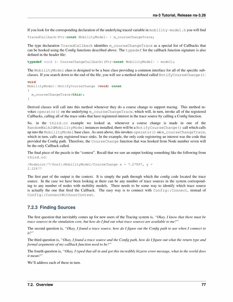
ns-3 Tutorial, Release ns-3.26
If you look for the corresponding declaration of the underlying traced variable in mobility-model.h you will find
TracedCallback<Ptr<const MobilityModel> > m_courseChangeTrace;
The type declaration TracedCallback identifies m_courseChangeTrace as a special list of Callbacks thatcan be hooked using the Config functions described above. The typedef for the callback function signature is alsodefined in the header file:
typedef void (* CourseChangeCallback)(Ptr<const MobilityModel> * model);
The MobilityModel class is designed to be a base class providing a common interface for all of the specific sub-classes. If you search down to the end of the file, you will see a method defined called NotifyCourseChange():
voidMobilityModel::NotifyCourseChange (void) const{
m_courseChangeTrace(this);}
Derived classes will call into this method whenever they do a course change to support tracing. This method in-vokes operator() on the underlying m_courseChangeTrace, which will, in turn, invoke all of the registeredCallbacks, calling all of the trace sinks that have registered interest in the trace source by calling a Config function.
So, in the third.cc example we looked at, whenever a course change is made in one of theRandomWalk2dMobilityModel instances installed, there will be a NotifyCourseChange() call which callsup into the MobilityModel base class. As seen above, this invokes operator() on m_courseChangeTrace,which in turn, calls any registered trace sinks. In the example, the only code registering an interest was the code thatprovided the Config path. Therefore, the CourseChange function that was hooked from Node number seven willbe the only Callback called.
The final piece of the puzzle is the “context”. Recall that we saw an output looking something like the following fromthird.cc:
/NodeList/7/$ns3::MobilityModel/CourseChange x = 7.27897, y =2.22677
The first part of the output is the context. It is simply the path through which the config code located the tracesource. In the case we have been looking at there can be any number of trace sources in the system correspond-ing to any number of nodes with mobility models. There needs to be some way to identify which trace sourceis actually the one that fired the Callback. The easy way is to connect with Config::Connect, instead ofConfig::ConnectWithoutContext.
7.2.3 Finding Sources
The first question that inevitably comes up for new users of the Tracing system is, “Okay, I know that there must betrace sources in the simulation core, but how do I find out what trace sources are available to me?”
The second question is, “Okay, I found a trace source, how do I figure out the Config path to use when I connect toit?”
The third question is, “Okay, I found a trace source and the Config path, how do I figure out what the return type andformal arguments of my callback function need to be?”
The fourth question is, “Okay, I typed that all in and got this incredibly bizarre error message, what in the world doesit mean?”
We’ll address each of these in turn.
7.2. Overview 77

ns-3 Tutorial, Release ns-3.26
7.2.4 Available Sources
Okay, I know that there must be trace sources in the simulation core, but how do I find out what trace sources areavailable to me?
The answer to the first question is found in the ns-3 API documentation. If you go to the project web site, ns-3project, you will find a link to “Documentation” in the navigation bar. If you select this link, you will be taken to ourdocumentation page. There is a link to “Latest Release” that will take you to the documentation for the latest stablerelease of ns-3. If you select the “API Documentation” link, you will be taken to the ns-3 API documentation page.
In the sidebar you should see a hierachy that begins
• ns-3
• ns-3 Documentation
• All TraceSources
• All Attributes
• All GlobalValues
The list of interest to us here is “All TraceSources”. Go ahead and select that link. You will see, perhaps not toosurprisingly, a list of all of the trace sources available in ns-3.
As an example, scroll down to ns3::MobilityModel. You will find an entry for
CourseChange: The value of the position and/or velocity vector changed
You should recognize this as the trace source we used in the third.cc example. Perusing this list will be helpful.
7.2.5 Config Paths
Okay, I found a trace source, how do I figure out the Config path to use when I connect to it?
If you know which object you are interested in, the “Detailed Description” section for the class will list all availabletrace sources. For example, starting from the list of “All TraceSources,” click on the ns3::MobilityModel link,which will take you to the documentation for the MobilityModel class. Almost at the top of the page is a one linebrief description of the class, ending in a link “More...”. Click on this link to skip the API summary and go to the“Detailed Description” of the class. At the end of the description will be (up to) three lists:
• Config Paths: a list of typical Config paths for this class.
• Attributes: a list of all attributes supplied by this class.
• TraceSources: a list of all TraceSources available from this class.
First we’ll discuss the Config paths.
Let’s assume that you have just found the “CourseChange” trace source in the “All TraceSources” list and youwant to figure out how to connect to it. You know that you are using (again, from the third.cc example) anns3::RandomWalk2dMobilityModel. So either click on the class name in the “All TraceSources” list, orfind ns3::RandomWalk2dMobilityModel in the “Class List”. Either way you should now be looking at the“ns3::RandomWalk2dMobilityModel Class Reference” page.
If you now scroll down to the “Detailed Description” section, after the summary list of class methods and attributes (orjust click on the “More...” link at the end of the class brief description at the top of the page) you will see the overalldocumentation for the class. Continuing to scroll down, find the “Config Paths” list:
Config Paths
ns3::RandomWalk2dMobilityModel is accessible through the following paths withConfig::Set and Config::Connect:
78 Chapter 7. Tracing

ns-3 Tutorial, Release ns-3.26
• “/NodeList/[i]/$ns3::MobilityModel/$ns3::RandomWalk2dMobilityModel”
The documentation tells you how to get to the RandomWalk2dMobilityModel Object. Compare the string abovewith the string we actually used in the example code:
"/NodeList/7/$ns3::MobilityModel"
The difference is due to the fact that two GetObject calls are implied in the string found in the documentation. Thefirst, for $ns3::MobilityModel will query the aggregation for the base class. The second implied GetObjectcall, for $ns3::RandomWalk2dMobilityModel, is used to cast the base class to the concrete implementationclass. The documentation shows both of these operations for you. It turns out that the actual trace source you arelooking for is found in the base class.
Look further down in the “Detailed Description” section for the list of trace sources. You will find
No TraceSources are defined for this type.
TraceSources defined in parent class ‘‘ns3::MobilityModel‘‘
• CourseChange: The value of the position and/or velocity vector changed.
Callback signature: ns3::MobilityModel::CourseChangeCallback
This is exactly what you need to know. The trace source of interest is found in ns3::MobilityModel (which youknew anyway). The interesting thing this bit of API Documentation tells you is that you don’t need that extra cast inthe config path above to get to the concrete class, since the trace source is actually in the base class. Therefore theadditional GetObject is not required and you simply use the path:
"/NodeList/[i]/$ns3::MobilityModel"
which perfectly matches the example path:
"/NodeList/7/$ns3::MobilityModel"
As an aside, another way to find the Config path is to grep around in the ns-3 codebase for someone who has alreadyfigured it out. You should always try to copy someone else’s working code before you start to write your own. Trysomething like:
$ find . -name '*.cc' | xargs grep CourseChange | grep Connect
and you may find your answer along with working code. For example, in this case,src/mobility/examples/main-random-topology.cc has something just waiting for you to use:
Config::Connect ("/NodeList/*/$ns3::MobilityModel/CourseChange",MakeCallback (&CourseChange));
We’ll return to this example in a moment.
7.2.6 Callback Signatures
Okay, I found a trace source and the Config path, how do I figure out what the return type and formal arguments ofmy callback function need to be?
The easiest way is to examine the callback signature typedef, which is given in the “Callback signature” of the tracesource in the “Detailed Description” for the class, as shown above.
Repeating the “CourseChange” trace source entry from ns3::RandomWalk2dMobilityModel we have:
• CourseChange: The value of the position and/or velocity vector changed.
Callback signature: ns3::MobilityModel::CourseChangeCallback
7.2. Overview 79

ns-3 Tutorial, Release ns-3.26
The callback signature is given as a link to the relevant typedef, where we find
typedef void (* CourseChangeCallback)(std::string context, Ptr<constMobilityModel> * model);
TracedCallback signature for course change notifications.
If the callback is connected using ConnectWithoutContext omit the context argument from thesignature.
Parameters:
[in] context The context string supplied by the Trace source.[in] model The MobilityModel which is changing course.
As above, to see this in use grep around in the ns-3 codebase for an example. The example above, fromsrc/mobility/examples/main-random-topology.cc, connects the “CourseChange” trace source to theCourseChange function in the same file:
static voidCourseChange (std::string context, Ptr<const MobilityModel> model){
...}
Notice that this function:
• Takes a “context” string argument, which we’ll describe in a minute. (If the callback is connected using theConnectWithoutContext function the context argument will be omitted.)
• Has the MobilityModel supplied as the last argument (or only argument if ConnectWithoutContextis used).
• Returns void.
If, by chance, the callback signature hasn’t been documented, and there are no examples to work from, determiningthe right callback function signature can be, well, challenging to actually figure out from the source code.
Before embarking on a walkthrough of the code, I’ll be kind and just tell you a simple way to figure this out: The returnvalue of your callback will always be void. The formal parameter list for a TracedCallback can be found fromthe template parameter list in the declaration. Recall that for our current example, this is in mobility-model.h,where we have previously found:
TracedCallback<Ptr<const MobilityModel> > m_courseChangeTrace;
There is a one-to-one correspondence between the template parameter list in the declaration and the formal argumentsof the callback function. Here, there is one template parameter, which is a Ptr<const MobilityModel>. Thistells you that you need a function that returns void and takes a Ptr<const MobilityModel>. For example:
voidCourseChange (Ptr<const MobilityModel> model){
...}
That’s all you need if you want to Config::ConnectWithoutContext. If you want a context, you need toConfig::Connect and use a Callback function that takes a string context, then the template arguments:
voidCourseChange (std::string context, Ptr<const MobilityModel> model){
80 Chapter 7. Tracing

ns-3 Tutorial, Release ns-3.26
...}
If you want to ensure that your CourseChangeCallback function is only visible in your local file, you can addthe keyword static and come up with:
static voidCourseChange (std::string path, Ptr<const MobilityModel> model){
...}
which is exactly what we used in the third.cc example.
Implementation
This section is entirely optional. It is going to be a bumpy ride, especially for those unfamiliar with the details oftemplates. However, if you get through this, you will have a very good handle on a lot of the ns-3 low level idioms.
So, again, let’s figure out what signature of callback function is required for the “CourseChange” trace source. Thisis going to be painful, but you only need to do this once. After you get through this, you will be able to just look at aTracedCallback and understand it.
The first thing we need to look at is the declaration of the trace source. Recall that this is in mobility-model.h,where we have previously found:
TracedCallback<Ptr<const MobilityModel> > m_courseChangeTrace;
This declaration is for a template. The template parameter is inside the angle-brackets, so we are really interested infinding out what that TracedCallback<> is. If you have absolutely no idea where this might be found, grep isyour friend.
We are probably going to be interested in some kind of declaration in the ns-3 source, so first change into the srcdirectory. Then, we know this declaration is going to have to be in some kind of header file, so just grep for it using:
$ find . -name '*.h' | xargs grep TracedCallback
You’ll see 303 lines fly by (I piped this through wc to see how bad it was). Although that may seem like a lot, that’snot really a lot. Just pipe the output through more and start scanning through it. On the first page, you will see somevery suspiciously template-looking stuff.
TracedCallback<T1,T2,T3,T4,T5,T6,T7,T8>::TracedCallback ()TracedCallback<T1,T2,T3,T4,T5,T6,T7,T8>::ConnectWithoutContext (c ...TracedCallback<T1,T2,T3,T4,T5,T6,T7,T8>::Connect (const CallbackB ...TracedCallback<T1,T2,T3,T4,T5,T6,T7,T8>::DisconnectWithoutContext ...TracedCallback<T1,T2,T3,T4,T5,T6,T7,T8>::Disconnect (const Callba ...TracedCallback<T1,T2,T3,T4,T5,T6,T7,T8>::operator() (void) const ...TracedCallback<T1,T2,T3,T4,T5,T6,T7,T8>::operator() (T1 a1) const ...TracedCallback<T1,T2,T3,T4,T5,T6,T7,T8>::operator() (T1 a1, T2 a2 ...TracedCallback<T1,T2,T3,T4,T5,T6,T7,T8>::operator() (T1 a1, T2 a2 ...TracedCallback<T1,T2,T3,T4,T5,T6,T7,T8>::operator() (T1 a1, T2 a2 ...TracedCallback<T1,T2,T3,T4,T5,T6,T7,T8>::operator() (T1 a1, T2 a2 ...TracedCallback<T1,T2,T3,T4,T5,T6,T7,T8>::operator() (T1 a1, T2 a2 ...TracedCallback<T1,T2,T3,T4,T5,T6,T7,T8>::operator() (T1 a1, T2 a2 ...
It turns out that all of this comes from the header file traced-callback.h which sounds very promising. You canthen take a look at mobility-model.h and see that there is a line which confirms this hunch:
7.2. Overview 81

ns-3 Tutorial, Release ns-3.26
#include "ns3/traced-callback.h"
Of course, you could have gone at this from the other direction and started by looking at the includes inmobility-model.h and noticing the include of traced-callback.h and inferring that this must be the fileyou want.
In either case, the next step is to take a look at src/core/model/traced-callback.h in your favorite editorto see what is happening.
You will see a comment at the top of the file that should be comforting:
An ns3::TracedCallback has almost exactly the same API as a normal ns3::Callback but instead of for-warding calls to a single function (as an ns3::Callback normally does), it forwards calls to a chain ofns3::Callback.
This should sound very familiar and let you know you are on the right track.
Just after this comment, you will find
template<typename T1 = empty, typename T2 = empty,typename T3 = empty, typename T4 = empty,typename T5 = empty, typename T6 = empty,typename T7 = empty, typename T8 = empty>
class TracedCallback{
...
This tells you that TracedCallback is a templated class. It has eight possible type parameters with default values. Goback and compare this with the declaration you are trying to understand:
TracedCallback<Ptr<const MobilityModel> > m_courseChangeTrace;
The typename T1 in the templated class declaration corresponds to the Ptr<const MobilityModel> in thedeclaration above. All of the other type parameters are left as defaults. Looking at the constructor really doesn’ttell you much. The one place where you have seen a connection made between your Callback function and thetracing system is in the Connect and ConnectWithoutContext functions. If you scroll down, you will see aConnectWithoutContext method here:
template<typename T1, typename T2,typename T3, typename T4,typename T5, typename T6,typename T7, typename T8>
voidTracedCallback<T1,T2,T3,T4,T5,T6,T7,T8>::ConnectWithoutContext ...{
Callback<void,T1,T2,T3,T4,T5,T6,T7,T8> cb;cb.Assign (callback);m_callbackList.push_back (cb);
}
You are now in the belly of the beast. When the template is instantiated for the declaration above, the compiler willreplace T1 with Ptr<const MobilityModel>.
voidTracedCallback<Ptr<const MobilityModel>::ConnectWithoutContext ... cb{
Callback<void, Ptr<const MobilityModel> > cb;cb.Assign (callback);m_callbackList.push_back (cb);
}
82 Chapter 7. Tracing

ns-3 Tutorial, Release ns-3.26
You can now see the implementation of everything we’ve been talking about. The code creates a Callback of the righttype and assigns your function to it. This is the equivalent of the pfi = MyFunction we discussed at the start ofthis section. The code then adds the Callback to the list of Callbacks for this source. The only thing left is to look atthe definition of Callback. Using the same grep trick as we used to find TracedCallback, you will be able tofind that the file ./core/callback.h is the one we need to look at.
If you look down through the file, you will see a lot of probably almost incomprehensible template code. You willeventually come to some API Documentation for the Callback template class, though. Fortunately, there is someEnglish:
Callback template class.
This class template implements the Functor Design Pattern. It is used to declare the type of a Callback:
• the first non-optional template argument represents the return type of the callback.
• the reminaining (optional) template arguments represent the type of the subsequent arguments to thecallback.
• up to nine arguments are supported.
We are trying to figure out what the
Callback<void, Ptr<const MobilityModel> > cb;
declaration means. Now we are in a position to understand that the first (non-optional) template argument, void, rep-resents the return type of the Callback. The second (optional) template argument, Ptr<const MobilityModel>represents the type of the first argument to the callback.
The Callback in question is your function to receive the trace events. From this you can infer that you need a functionthat returns void and takes a Ptr<const MobilityModel>. For example,
voidCourseChangeCallback (Ptr<const MobilityModel> model){
...}
That’s all you need if you want to Config::ConnectWithoutContext. If you want a context, you need toConfig::Connect and use a Callback function that takes a string context. This is because the Connect functionwill provide the context for you. You’ll need:
voidCourseChangeCallback (std::string context, Ptr<const MobilityModel> model){
...}
If you want to ensure that your CourseChangeCallback is only visible in your local file, you can add the keywordstatic and come up with:
static voidCourseChangeCallback (std::string path, Ptr<const MobilityModel> model){
...}
which is exactly what we used in the third.cc example. Perhaps you should now go back and reread the previoussection (Take My Word for It).
If you are interested in more details regarding the implementation of Callbacks, feel free to take a look at the ns-3manual. They are one of the most frequently used constructs in the low-level parts of ns-3. It is, in my opinion, a quite
7.2. Overview 83

ns-3 Tutorial, Release ns-3.26
elegant thing.
7.2.7 TracedValues
Earlier in this section, we presented a simple piece of code that used a TracedValue<int32_t> to demonstratethe basics of the tracing code. We just glossed over the what a TracedValue really is and how to find the return typeand formal arguments for the callback.
As we mentioned, the file, traced-value.h brings in the required declarations for tracing of data that obeys valuesemantics. In general, value semantics just means that you can pass the object itself around, rather than passingthe address of the object. We extend that requirement to include the full set of assignment-style operators that arepre-defined for plain-old-data (POD) types:
operator= (assignment)operator*= operator/=operator+= operator-=operator++ (both prefix and postfix)operator-- (both prefix and postfix)operator<<= operator>>=operator&= operator|=operator%= operator^=
What this all really means is that you will be able to trace all changes made using those operators to a C++ objectwhich has value semantics.
The TracedValue<> declaration we saw above provides the infrastructure that overloads the operators mentionedabove and drives the callback process. On use of any of the operators above with a TracedValue it will provide boththe old and the new value of that variable, in this case an int32_t value. By inspection of the TracedValue dec-laration, we know the trace sink function will have arguments (int32_t oldValue, int32_t newValue).The return type for a TracedValue callback function is always void, so the expected callback signature for thesink function traceSink will be:
void (* traceSink)(int32_t oldValue, int32_t newValue);
The .AddTraceSource in the GetTypeId method provides the “hooks” used for connecting the trace source tothe outside world through the Config system. We already discussed the first three agruments to AddTraceSource:the Attribute name for the Config system, a help string, and the address of the TracedValue class data member.
The final string argument, “ns3::TracedValueCallback::Int32” in the example, is the name of a typedef for thecallback function signature. We require these signatures to be defined, and give the fully qualified type name toAddTraceSource, so the API documentation can link a trace source to the function signature. For TracedValue thesignature is straightforward; for TracedCallbacks we’ve already seen the API docs really help.
7.3 Real Example
Let’s do an example taken from one of the best-known books on TCP around. “TCP/IP Illustrated, Volume 1: TheProtocols,” by W. Richard Stevens is a classic. I just flipped the book open and ran across a nice plot of both thecongestion window and sequence numbers versus time on page 366. Stevens calls this, “Figure 21.10. Value of cwndand send sequence number while data is being transmitted.” Let’s just recreate the cwnd part of that plot in ns-3 usingthe tracing system and gnuplot.
84 Chapter 7. Tracing

ns-3 Tutorial, Release ns-3.26
7.3.1 Available Sources
The first thing to think about is how we want to get the data out. What is it that we need to trace? So let’s consult “AllTrace Sources” list to see what we have to work with. Recall that this is found in the ns-3 API Documentation. If youscroll through the list, you will eventually find:
ns3::TcpSocketBase
• CongestionWindow: The TCP connection’s congestion window
• SlowStartThreshold: TCP slow start threshold (bytes)
It turns out that the ns-3 TCP implementation lives (mostly) in the filesrc/internet/model/tcp-socket-base.cc while congestion control variants are in files such assrc/internet/model/tcp-bic.cc. If you don’t know this a priori, you can use the recursive grep trick:
$ find . -name '*.cc' | xargs grep -i tcp
You will find page after page of instances of tcp pointing you to that file.
Bringing up the class documentation for TcpSocketBase and skipping to the list of TraceSources you will find
TraceSources
• CongestionWindow: The TCP connnection’s congestion window
Callback signature: ns3::TracedValueCallback::Uint32
Clicking on the callback typedef link we see the signature you now know to expect:
typedef void(* ns3::TracedValueCallback::Int32)(int32_t oldValue, int32_t newValue)
You should now understand this code completely. If we have a pointer to the TcpSocketBase object, we canTraceConnect to the “CongestionWindow” trace source if we provide an appropriate callback target. This is thesame kind of trace source that we saw in the simple example at the start of this section, except that we are talking aboutuint32_t instead of int32_t. And we know that we have to provide a callback function with that signature.
7.3.2 Finding Examples
It’s always best to try and find working code laying around that you can modify, rather than starting from scratch. Sothe first order of business now is to find some code that already hooks the “CongestionWindow” trace source and seeif we can modify it. As usual, grep is your friend:
$ find . -name '*.cc' | xargs grep CongestionWindow
This will point out a couple of promising candidates: examples/tcp/tcp-large-transfer.cc andsrc/test/ns3tcp/ns3tcp-cwnd-test-suite.cc.
We haven’t visited any of the test code yet, so let’s take a look there. You will typically find that test code is fairlyminimal, so this is probably a very good bet. Open src/test/ns3tcp/ns3tcp-cwnd-test-suite.cc inyour favorite editor and search for “CongestionWindow”. You will find,
ns3TcpSocket->TraceConnectWithoutContext ("CongestionWindow",MakeCallback (&Ns3TcpCwndTestCase1::CwndChange, this));
This should look very familiar to you. We mentioned above that if we had a pointer to the TcpSocketBase, wecould TraceConnect to the “CongestionWindow” trace source. That’s exactly what we have here; so it turns outthat this line of code does exactly what we want. Let’s go ahead and extract the code we need from this function(Ns3TcpCwndTestCase1::DoRun (void)). If you look at this function, you will find that it looks just like anns-3 script. It turns out that is exactly what it is. It is a script run by the test framework, so we can just pull it out
7.3. Real Example 85

ns-3 Tutorial, Release ns-3.26
and wrap it in main instead of in DoRun. Rather than walk through this, step, by step, we have provided the file thatresults from porting this test back to a native ns-3 script – examples/tutorial/fifth.cc.
7.3.3 Dynamic Trace Sources
The fifth.cc example demonstrates an extremely important rule that you must understand before using any kindof trace source: you must ensure that the target of a Config::Connect command exists before trying to use it.This is no different than saying an object must be instantiated before trying to call it. Although this may seem obviouswhen stated this way, it does trip up many people trying to use the system for the first time.
Let’s return to basics for a moment. There are three basic execution phases that exist in any ns-3 script. The first phaseis sometimes called “Configuration Time” or “Setup Time,” and exists during the period when the main function ofyour script is running, but before Simulator::Run is called. The second phase is sometimes called “SimulationTime” and exists during the time period when Simulator::Run is actively executing its events. After it completesexecuting the simulation, Simulator::Run will return control back to the main function. When this happens, thescript enters what can be called the “Teardown Phase,” which is when the structures and objects created during setupare taken apart and released.
Perhaps the most common mistake made in trying to use the tracing system is assuming that entities constructed dy-namically during simulation time are available during configuration time. In particular, an ns-3 Socket is a dynamicobject often created by Applications to communicate between Nodes. An ns-3 Application always has a“Start Time” and a “Stop Time” associated with it. In the vast majority of cases, an Application will not attempt tocreate a dynamic object until its StartApplication method is called at some “Start Time”. This is to ensure thatthe simulation is completely configured before the app tries to do anything (what would happen if it tried to connect toa Node that didn’t exist yet during configuration time?). As a result, during the configuration phase you can’t connecta trace source to a trace sink if one of them is created dynamically during the simulation.
The two solutions to this connundrum are
1. Create a simulator event that is run after the dynamic object is created and hook the trace when that event isexecuted; or
2. Create the dynamic object at configuration time, hook it then, and give the object to the system to use duringsimulation time.
We took the second approach in the fifth.cc example. This decision required us to create the MyAppApplication, the entire purpose of which is to take a Socket as a parameter.
7.3.4 Walkthrough: fifth.cc
Now, let’s take a look at the example program we constructed by dissecting the congestion window test. Openexamples/tutorial/fifth.cc in your favorite editor. You should see some familiar looking code:
/* -*- Mode:C++; c-file-style:"gnu"; indent-tabs-mode:nil; -*- *//** This program is free software; you can redistribute it and/or modify
* it under the terms of the GNU General Public License version 2 as
* published by the Free Software Foundation;
** This program is distributed in the hope that it will be useful,
* but WITHOUT ANY WARRANTY; without even the implied warranty of
* MERCHANTABILITY or FITNESS FOR A PARTICULAR PURPOSE. See the
* GNU General Public License for more details.
** You should have received a copy of the GNU General Public License
* along with this program; if not, write to the Free Software
86 Chapter 7. Tracing

ns-3 Tutorial, Release ns-3.26
* Foundation, Include., 59 Temple Place, Suite 330, Boston, MA 02111-1307 USA
*/
#include <fstream>#include "ns3/core-module.h"#include "ns3/network-module.h"#include "ns3/internet-module.h"#include "ns3/point-to-point-module.h"#include "ns3/applications-module.h"
using namespace ns3;
NS_LOG_COMPONENT_DEFINE ("FifthScriptExample");
This has all been covered, so we won’t rehash it. The next lines of source are the network illustration and a commentaddressing the problem described above with Socket.
// ===========================================================================//// node 0 node 1// +----------------+ +----------------+// | ns-3 TCP | | ns-3 TCP |// +----------------+ +----------------+// | 10.1.1.1 | | 10.1.1.2 |// +----------------+ +----------------+// | point-to-point | | point-to-point |// +----------------+ +----------------+// | |// +---------------------+// 5 Mbps, 2 ms////// We want to look at changes in the ns-3 TCP congestion window. We need// to crank up a flow and hook the CongestionWindow attribute on the socket// of the sender. Normally one would use an on-off application to generate a// flow, but this has a couple of problems. First, the socket of the on-off// application is not created until Application Start time, so we wouldn't be// able to hook the socket (now) at configuration time. Second, even if we// could arrange a call after start time, the socket is not public so we// couldn't get at it.//// So, we can cook up a simple version of the on-off application that does what// we want. On the plus side we don't need all of the complexity of the on-off// application. On the minus side, we don't have a helper, so we have to get// a little more involved in the details, but this is trivial.//// So first, we create a socket and do the trace connect on it; then we pass// this socket into the constructor of our simple application which we then// install in the source node.// ===========================================================================//
This should also be self-explanatory.
The next part is the declaration of the MyApp Application that we put together to allow the Socket to be createdat configuration time.
class MyApp : public Application{
7.3. Real Example 87

ns-3 Tutorial, Release ns-3.26
public:
MyApp ();virtual ~MyApp();
void Setup (Ptr<Socket> socket, Address address, uint32_t packetSize,uint32_t nPackets, DataRate dataRate);
private:virtual void StartApplication (void);virtual void StopApplication (void);
void ScheduleTx (void);void SendPacket (void);
Ptr<Socket> m_socket;Address m_peer;uint32_t m_packetSize;uint32_t m_nPackets;DataRate m_dataRate;EventId m_sendEvent;bool m_running;uint32_t m_packetsSent;
};
You can see that this class inherits from the ns-3 Application class. Take a look atsrc/network/model/application.h if you are interested in what is inherited. The MyApp class isobligated to override the StartApplication and StopApplication methods. These methods are automati-cally called when MyApp is required to start and stop sending data during the simulation.
Starting/Stopping Applications
It is worthwhile to spend a bit of time explaining how events actually get started in the system. This is another fairlydeep explanation, and can be ignored if you aren’t planning on venturing down into the guts of the system. It is useful,however, in that the discussion touches on how some very important parts of ns-3 work and exposes some importantidioms. If you are planning on implementing new models, you probably want to understand this section.
The most common way to start pumping events is to start an Application. This is done as the result of the following(hopefully) familar lines of an ns-3 script:
ApplicationContainer apps = ...apps.Start (Seconds (1.0));apps.Stop (Seconds (10.0));
The application container code (see src/network/helper/application-container.h if you are inter-ested) loops through its contained applications and calls,
app->SetStartTime (startTime);
as a result of the apps.Start call and
app->SetStopTime (stopTime);
as a result of the apps.Stop call.
The ultimate result of these calls is that we want to have the simulator automatically make calls into ourApplications to tell them when to start and stop. In the case of MyApp, it inherits from class Applicationand overrides StartApplication, and StopApplication. These are the functions that will be called by the
88 Chapter 7. Tracing
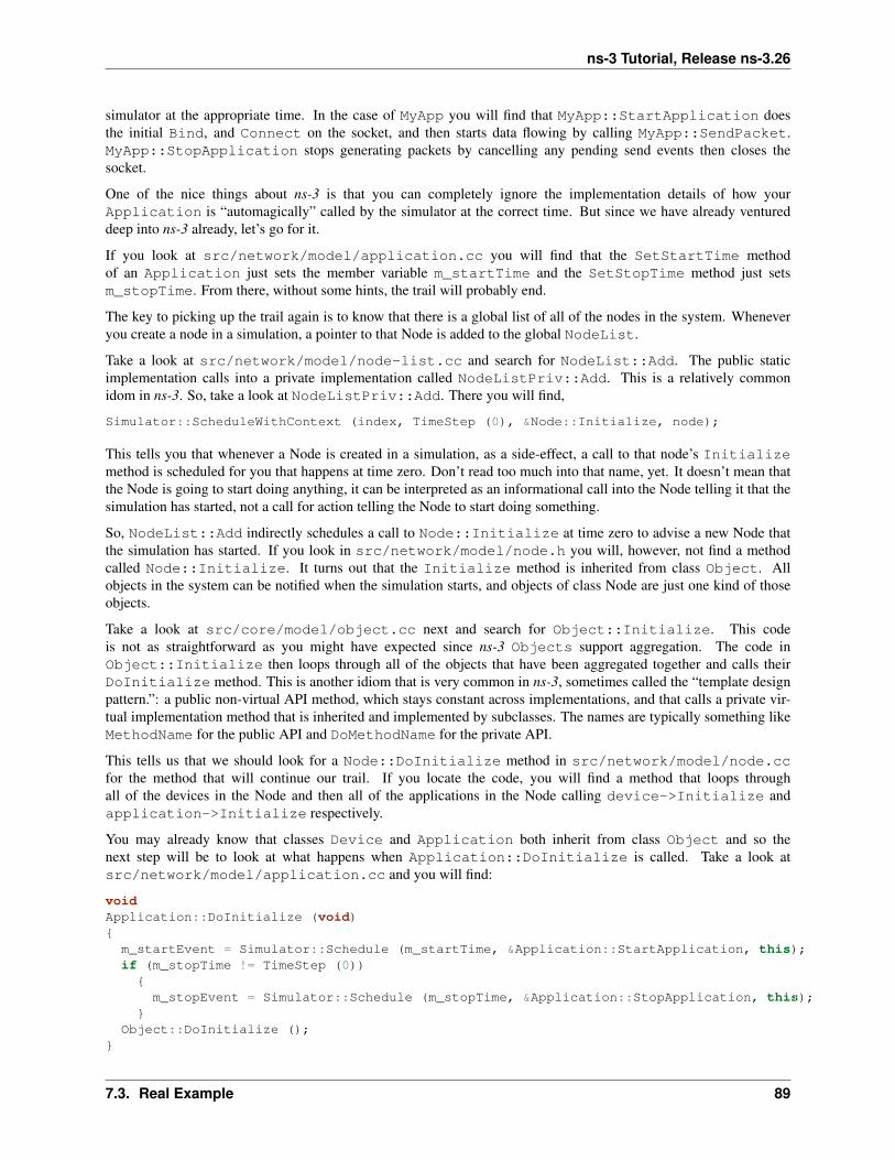
ns-3 Tutorial, Release ns-3.26
simulator at the appropriate time. In the case of MyApp you will find that MyApp::StartApplication doesthe initial Bind, and Connect on the socket, and then starts data flowing by calling MyApp::SendPacket.MyApp::StopApplication stops generating packets by cancelling any pending send events then closes thesocket.
One of the nice things about ns-3 is that you can completely ignore the implementation details of how yourApplication is “automagically” called by the simulator at the correct time. But since we have already ventureddeep into ns-3 already, let’s go for it.
If you look at src/network/model/application.cc you will find that the SetStartTime methodof an Application just sets the member variable m_startTime and the SetStopTime method just setsm_stopTime. From there, without some hints, the trail will probably end.
The key to picking up the trail again is to know that there is a global list of all of the nodes in the system. Wheneveryou create a node in a simulation, a pointer to that Node is added to the global NodeList.
Take a look at src/network/model/node-list.cc and search for NodeList::Add. The public staticimplementation calls into a private implementation called NodeListPriv::Add. This is a relatively commonidom in ns-3. So, take a look at NodeListPriv::Add. There you will find,
Simulator::ScheduleWithContext (index, TimeStep (0), &Node::Initialize, node);
This tells you that whenever a Node is created in a simulation, as a side-effect, a call to that node’s Initializemethod is scheduled for you that happens at time zero. Don’t read too much into that name, yet. It doesn’t mean thatthe Node is going to start doing anything, it can be interpreted as an informational call into the Node telling it that thesimulation has started, not a call for action telling the Node to start doing something.
So, NodeList::Add indirectly schedules a call to Node::Initialize at time zero to advise a new Node thatthe simulation has started. If you look in src/network/model/node.h you will, however, not find a methodcalled Node::Initialize. It turns out that the Initialize method is inherited from class Object. Allobjects in the system can be notified when the simulation starts, and objects of class Node are just one kind of thoseobjects.
Take a look at src/core/model/object.cc next and search for Object::Initialize. This codeis not as straightforward as you might have expected since ns-3 Objects support aggregation. The code inObject::Initialize then loops through all of the objects that have been aggregated together and calls theirDoInitialize method. This is another idiom that is very common in ns-3, sometimes called the “template designpattern.”: a public non-virtual API method, which stays constant across implementations, and that calls a private vir-tual implementation method that is inherited and implemented by subclasses. The names are typically something likeMethodName for the public API and DoMethodName for the private API.
This tells us that we should look for a Node::DoInitialize method in src/network/model/node.ccfor the method that will continue our trail. If you locate the code, you will find a method that loops throughall of the devices in the Node and then all of the applications in the Node calling device->Initialize andapplication->Initialize respectively.
You may already know that classes Device and Application both inherit from class Object and so thenext step will be to look at what happens when Application::DoInitialize is called. Take a look atsrc/network/model/application.cc and you will find:
voidApplication::DoInitialize (void){
m_startEvent = Simulator::Schedule (m_startTime, &Application::StartApplication, this);if (m_stopTime != TimeStep (0)){
m_stopEvent = Simulator::Schedule (m_stopTime, &Application::StopApplication, this);}
Object::DoInitialize ();}
7.3. Real Example 89

ns-3 Tutorial, Release ns-3.26
Here, we finally come to the end of the trail. If you have kept it all straight, when you implement an ns-3Application, your new application inherits from class Application. You override the StartApplicationand StopApplicationmethods and provide mechanisms for starting and stopping the flow of data out of your newApplication. When a Node is created in the simulation, it is added to a global NodeList. The act of adding aNode to this NodeList causes a simulator event to be scheduled for time zero which calls the Node::Initializemethod of the newly added Node to be called when the simulation starts. Since a Node inherits from Object,this calls the Object::Initialize method on the Node which, in turn, calls the DoInitialize methodson all of the Objects aggregated to the Node (think mobility models). Since the Node Object has overriddenDoInitialize, that method is called when the simulation starts. The Node::DoInitialize method calls theInitialize methods of all of the Applications on the node. Since Applications are also Objects,this causes Application::DoInitialize to be called. When Application::DoInitialize is called, itschedules events for the StartApplication and StopApplication calls on the Application. These callsare designed to start and stop the flow of data from the Application
This has been another fairly long journey, but it only has to be made once, and you now understand another very deeppiece of ns-3.
The MyApp Application
The MyApp Application needs a constructor and a destructor, of course:
MyApp::MyApp (): m_socket (0),m_peer (),m_packetSize (0),m_nPackets (0),m_dataRate (0),m_sendEvent (),m_running (false),m_packetsSent (0)
{}
MyApp::~MyApp(){
m_socket = 0;}
The existence of the next bit of code is the whole reason why we wrote this Application in the first place.
voidMyApp::Setup (Ptr<Socket> socket, Address address, uint32_t packetSize,
uint32_t nPackets, DataRate dataRate){
m_socket = socket;m_peer = address;m_packetSize = packetSize;m_nPackets = nPackets;m_dataRate = dataRate;
}
This code should be pretty self-explanatory. We are just initializing member variables. The important one fromthe perspective of tracing is the Ptr<Socket> socket which we needed to provide to the application duringconfiguration time. Recall that we are going to create the Socket as a TcpSocket (which is implemented byTcpSocketBase) and hook its “CongestionWindow” trace source before passing it to the Setup method.
90 Chapter 7. Tracing

ns-3 Tutorial, Release ns-3.26
voidMyApp::StartApplication (void){
m_running = true;m_packetsSent = 0;m_socket->Bind ();m_socket->Connect (m_peer);SendPacket ();
}
The above code is the overridden implementation Application::StartApplication that will be automati-cally called by the simulator to start our Application running at the appropriate time. You can see that it doesa Socket Bind operation. If you are familiar with Berkeley Sockets this shouldn’t be a surprise. It performs therequired work on the local side of the connection just as you might expect. The following Connect will do what isrequired to establish a connection with the TCP at Address m_peer. It should now be clear why we need to defer alot of this to simulation time, since the Connect is going to need a fully functioning network to complete. After theConnect, the Application then starts creating simulation events by calling SendPacket.
The next bit of code explains to the Application how to stop creating simulation events.
voidMyApp::StopApplication (void){
m_running = false;
if (m_sendEvent.IsRunning ()){
Simulator::Cancel (m_sendEvent);}
if (m_socket){
m_socket->Close ();}
}
Every time a simulation event is scheduled, an Event is created. If the Event is pending execution or executing, itsmethod IsRunning will return true. In this code, if IsRunning() returns true, we Cancel the event whichremoves it from the simulator event queue. By doing this, we break the chain of events that the Applicationis using to keep sending its Packets and the Application goes quiet. After we quiet the Application weClose the socket which tears down the TCP connection.
The socket is actually deleted in the destructor when the m_socket = 0 is executed. This removes the last referenceto the underlying Ptr<Socket> which causes the destructor of that Object to be called.
Recall that StartApplication called SendPacket to start the chain of events that describes theApplication behavior.
voidMyApp::SendPacket (void){
Ptr<Packet> packet = Create<Packet> (m_packetSize);m_socket->Send (packet);
if (++m_packetsSent < m_nPackets){
ScheduleTx ();}
}
7.3. Real Example 91

ns-3 Tutorial, Release ns-3.26
Here, you see that SendPacket does just that. It creates a Packet and then does a Send which, if you knowBerkeley Sockets, is probably just what you expected to see.
It is the responsibility of the Application to keep scheduling the chain of events, so the next lines callScheduleTx to schedule another transmit event (a SendPacket) until the Application decides it has sentenough.
voidMyApp::ScheduleTx (void){
if (m_running){
Time tNext (Seconds (m_packetSize * 8 / static_cast<double> (m_dataRate.GetBitRate ())));m_sendEvent = Simulator::Schedule (tNext, &MyApp::SendPacket, this);
}}
Here, you see that ScheduleTx does exactly that. If the Application is running (if StopApplication hasnot been called) it will schedule a new event, which calls SendPacket again. The alert reader will spot somethingthat also trips up new users. The data rate of an Application is just that. It has nothing to do with the data rate ofan underlying Channel. This is the rate at which the Application produces bits. It does not take into accountany overhead for the various protocols or channels that it uses to transport the data. If you set the data rate of anApplication to the same data rate as your underlying Channel you will eventually get a buffer overflow.
Trace Sinks
The whole point of this exercise is to get trace callbacks from TCP indicating the congestion window has been updated.The next piece of code implements the corresponding trace sink:
static voidCwndChange (uint32_t oldCwnd, uint32_t newCwnd){
NS_LOG_UNCOND (Simulator::Now ().GetSeconds () << "\t" << newCwnd);}
This should be very familiar to you now, so we won’t dwell on the details. This function just logs the current simulationtime and the new value of the congestion window every time it is changed. You can probably imagine that you couldload the resulting output into a graphics program (gnuplot or Excel) and immediately see a nice graph of the congestionwindow behavior over time.
We added a new trace sink to show where packets are dropped. We are going to add an error model to this code also,so we wanted to demonstrate this working.
static voidRxDrop (Ptr<const Packet> p){
NS_LOG_UNCOND ("RxDrop at " << Simulator::Now ().GetSeconds ());}
This trace sink will be connected to the “PhyRxDrop” trace source of the point-to-point NetDevice. Thistrace source fires when a packet is dropped by the physical layer of a NetDevice. If you take a smalldetour to the source (src/point-to-point/model/point-to-point-net-device.cc) you will seethat this trace source refers to PointToPointNetDevice::m_phyRxDropTrace. If you then look insrc/point-to-point/model/point-to-point-net-device.h for this member variable, you will findthat it is declared as a TracedCallback<Ptr<const Packet> >. This should tell you that the callback targetshould be a function that returns void and takes a single parameter which is a Ptr<const Packet> (assuming weuse ConnectWithoutContext) – just what we have above.
92 Chapter 7. Tracing
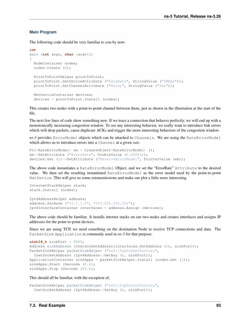
ns-3 Tutorial, Release ns-3.26
Main Program
The following code should be very familiar to you by now:
intmain (int argc, char *argv[]){
NodeContainer nodes;nodes.Create (2);
PointToPointHelper pointToPoint;pointToPoint.SetDeviceAttribute ("DataRate", StringValue ("5Mbps"));pointToPoint.SetChannelAttribute ("Delay", StringValue ("2ms"));
NetDeviceContainer devices;devices = pointToPoint.Install (nodes);
This creates two nodes with a point-to-point channel between them, just as shown in the illustration at the start of thefile.
The next few lines of code show something new. If we trace a connection that behaves perfectly, we will end up with amonotonically increasing congestion window. To see any interesting behavior, we really want to introduce link errorswhich will drop packets, cause duplicate ACKs and trigger the more interesting behaviors of the congestion window.
ns-3 provides ErrorModel objects which can be attached to Channels. We are using the RateErrorModelwhich allows us to introduce errors into a Channel at a given rate.
Ptr<RateErrorModel> em = CreateObject<RateErrorModel> ();em->SetAttribute ("ErrorRate", DoubleValue (0.00001));devices.Get (1)->SetAttribute ("ReceiveErrorModel", PointerValue (em));
The above code instantiates a RateErrorModel Object, and we set the “ErrorRate” Attribute to the desiredvalue. We then set the resulting instantiated RateErrorModel as the error model used by the point-to-pointNetDevice. This will give us some retransmissions and make our plot a little more interesting.
InternetStackHelper stack;stack.Install (nodes);
Ipv4AddressHelper address;address.SetBase ("10.1.1.0", "255.255.255.252");Ipv4InterfaceContainer interfaces = address.Assign (devices);
The above code should be familiar. It installs internet stacks on our two nodes and creates interfaces and assigns IPaddresses for the point-to-point devices.
Since we are using TCP, we need something on the destination Node to receive TCP connections and data. ThePacketSink Application is commonly used in ns-3 for that purpose.
uint16_t sinkPort = 8080;Address sinkAddress (InetSocketAddress(interfaces.GetAddress (1), sinkPort));PacketSinkHelper packetSinkHelper ("ns3::TcpSocketFactory",
InetSocketAddress (Ipv4Address::GetAny (), sinkPort));ApplicationContainer sinkApps = packetSinkHelper.Install (nodes.Get (1));sinkApps.Start (Seconds (0.));sinkApps.Stop (Seconds (20.));
This should all be familiar, with the exception of,
PacketSinkHelper packetSinkHelper ("ns3::TcpSocketFactory",InetSocketAddress (Ipv4Address::GetAny (), sinkPort));
7.3. Real Example 93

ns-3 Tutorial, Release ns-3.26
This code instantiates a PacketSinkHelper and tells it to create sockets using the classns3::TcpSocketFactory. This class implements a design pattern called “object factory” which is acommonly used mechanism for specifying a class used to create objects in an abstract way. Here, instead of having tocreate the objects themselves, you provide the PacketSinkHelper a string that specifies a TypeId string used tocreate an object which can then be used, in turn, to create instances of the Objects created by the factory.
The remaining parameter tells the Application which address and port it should Bind to.
The next two lines of code will create the socket and connect the trace source.
Ptr<Socket> ns3TcpSocket = Socket::CreateSocket (nodes.Get (0),TcpSocketFactory::GetTypeId ());
ns3TcpSocket->TraceConnectWithoutContext ("CongestionWindow",MakeCallback (&CwndChange));
The first statement calls the static member function Socket::CreateSocket and provides a Node and anexplicit TypeId for the object factory used to create the socket. This is a slightly lower level call than thePacketSinkHelper call above, and uses an explicit C++ type instead of one referred to by a string. Otherwise, itis conceptually the same thing.
Once the TcpSocket is created and attached to the Node, we can use TraceConnectWithoutContext toconnect the CongestionWindow trace source to our trace sink.
Recall that we coded an Application so we could take that Socket we just made (during configuration time) anduse it in simulation time. We now have to instantiate that Application. We didn’t go to any trouble to create ahelper to manage the Application so we are going to have to create and install it “manually”. This is actually quiteeasy:
Ptr<MyApp> app = CreateObject<MyApp> ();app->Setup (ns3TcpSocket, sinkAddress, 1040, 1000, DataRate ("1Mbps"));nodes.Get (0)->AddApplication (app);app->Start (Seconds (1.));app->Stop (Seconds (20.));
The first line creates an Object of type MyApp – our Application. The second line tells the Applicationwhat Socket to use, what address to connect to, how much data to send at each send event, how many send events togenerate and the rate at which to produce data from those events.
Next, we manually add the MyApp Application to the source Node and explicitly call the Start and Stopmethods on the Application to tell it when to start and stop doing its thing.
We need to actually do the connect from the receiver point-to-point NetDevice drop event to our RxDrop callbacknow.
devices.Get (1)->TraceConnectWithoutContext("PhyRxDrop", MakeCallback (&RxDrop));
It should now be obvious that we are getting a reference to the receiving Node NetDevice from its container andconnecting the trace source defined by the attribute “PhyRxDrop” on that device to the trace sink RxDrop.
Finally, we tell the simulator to override any Applications and just stop processing events at 20 seconds into thesimulation.
Simulator::Stop (Seconds(20));Simulator::Run ();Simulator::Destroy ();
return 0;}
Recall that as soon as Simulator::Run is called, configuration time ends, and simulation time begins. All of thework we orchestrated by creating the Application and teaching it how to connect and send data actually happens
94 Chapter 7. Tracing

ns-3 Tutorial, Release ns-3.26
during this function call.
As soon as Simulator::Run returns, the simulation is complete and we enter the teardown phase. In this case,Simulator::Destroy takes care of the gory details and we just return a success code after it completes.
7.3.5 Running fifth.cc
Since we have provided the file fifth.cc for you, if you have built your distribution (in debug mode since it usesNS_LOG – recall that optimized builds optimize out NS_LOG) it will be waiting for you to run.
$ ./waf --run fifthWaf: Entering directory `/home/craigdo/repos/ns-3-allinone-dev/ns-3-dev/build'Waf: Leaving directory `/home/craigdo/repos/ns-3-allinone-dev/ns-3-dev/build''build' finished successfully (0.684s)1 5361.0093 10721.01528 16081.02167 2144...1.11319 80401.12151 85761.12983 9112RxDrop at 1.13696...
You can probably see immediately a downside of using prints of any kind in your traces. We get those extraneous wafmessages printed all over our interesting information along with those RxDrop messages. We will remedy that soon,but I’m sure you can’t wait to see the results of all of this work. Let’s redirect that output to a file called cwnd.dat:
$ ./waf --run fifth > cwnd.dat 2>&1
Now edit up “cwnd.dat” in your favorite editor and remove the waf build status and drop lines, leaving only the traceddata (you could also comment out the TraceConnectWithoutContext("PhyRxDrop", MakeCallback(&RxDrop)); in the script to get rid of the drop prints just as easily.
You can now run gnuplot (if you have it installed) and tell it to generate some pretty pictures:
$ gnuplotgnuplot> set terminal png size 640,480gnuplot> set output "cwnd.png"gnuplot> plot "cwnd.dat" using 1:2 title 'Congestion Window' with linespointsgnuplot> exit
You should now have a graph of the congestion window versus time sitting in the file “cwnd.png” that looks like:
7.3.6 Using Mid-Level Helpers
In the previous section, we showed how to hook a trace source and get hopefully interesting information out ofa simulation. Perhaps you will recall that we called logging to the standard output using std::cout a “bluntinstrument” much earlier in this chapter. We also wrote about how it was a problem having to parse the log output inorder to isolate interesting information. It may have occurred to you that we just spent a lot of time implementing anexample that exhibits all of the problems we purport to fix with the ns-3 tracing system! You would be correct. But,bear with us. We’re not done yet.
One of the most important things we want to do is to is to have the ability to easily control the amount of outputcoming out of the simulation; and we also want to save those data to a file so we can refer back to it later. We can usethe mid-level trace helpers provided in ns-3 to do just that and complete the picture.
7.3. Real Example 95

ns-3 Tutorial, Release ns-3.26
96 Chapter 7. Tracing

ns-3 Tutorial, Release ns-3.26
We provide a script that writes the cwnd change and drop events developed in the example fifth.cc to disk inseparate files. The cwnd changes are stored as a tab-separated ASCII file and the drop events are stored in a PCAPfile. The changes to make this happen are quite small.
Walkthrough: sixth.cc
Let’s take a look at the changes required to go from fifth.cc to sixth.cc. Openexamples/tutorial/sixth.cc in your favorite editor. You can see the first change by searching forCwndChange. You will find that we have changed the signatures for the trace sinks and have added a single line toeach sink that writes the traced information to a stream representing a file.
static voidCwndChange (Ptr<OutputStreamWrapper> stream, uint32_t oldCwnd, uint32_t newCwnd){
NS_LOG_UNCOND (Simulator::Now ().GetSeconds () << "\t" << newCwnd);
*stream->GetStream () << Simulator::Now ().GetSeconds () << "\t" << oldCwnd << "\t" << newCwnd << std::endl;}
static voidRxDrop (Ptr<PcapFileWrapper> file, Ptr<const Packet> p){
NS_LOG_UNCOND ("RxDrop at " << Simulator::Now ().GetSeconds ());file->Write(Simulator::Now(), p);
}
We have added a “stream” parameter to the CwndChange trace sink. This is an object that holds (keeps safelyalive) a C++ output stream. It turns out that this is a very simple object, but one that manages lifetime issues forthe stream and solves a problem that even experienced C++ users run into. It turns out that the copy constructor forstd::ostream is marked private. This means that std::ostreams do not obey value semantics and cannot beused in any mechanism that requires the stream to be copied. This includes the ns-3 callback system, which as youmay recall, requires objects that obey value semantics. Further notice that we have added the following line in theCwndChange trace sink implementation:
*stream->GetStream () << Simulator::Now ().GetSeconds () << "\t" << oldCwnd << "\t" << newCwnd << std::endl;
This would be very familiar code if you replaced *stream->GetStream () with std::cout, as in:
std::cout << Simulator::Now ().GetSeconds () << "\t" << oldCwnd << "\t" << newCwnd << std::endl;
This illustrates that the Ptr<OutputStreamWrapper> is really just carrying around a std::ofstream foryou, and you can use it here like any other output stream.
A similar situation happens in RxDrop except that the object being passed around (a Ptr<PcapFileWrapper>)represents a PCAP file. There is a one-liner in the trace sink to write a timestamp and the contents of the packet beingdropped to the PCAP file:
file->Write(Simulator::Now(), p);
Of course, if we have objects representing the two files, we need to create them somewhere and also cause them to bepassed to the trace sinks. If you look in the main function, you will find new code to do just that:
AsciiTraceHelper asciiTraceHelper;Ptr<OutputStreamWrapper> stream = asciiTraceHelper.CreateFileStream ("sixth.cwnd");ns3TcpSocket->TraceConnectWithoutContext ("CongestionWindow", MakeBoundCallback (&CwndChange, stream));
...
PcapHelper pcapHelper;
7.3. Real Example 97

ns-3 Tutorial, Release ns-3.26
Ptr<PcapFileWrapper> file = pcapHelper.CreateFile ("sixth.pcap", std::ios::out, PcapHelper::DLT_PPP);devices.Get (1)->TraceConnectWithoutContext("PhyRxDrop", MakeBoundCallback (&RxDrop, file));
In the first section of the code snippet above, we are creating the ASCII trace file, creating an object responsible formanaging it and using a variant of the callback creation function to arrange for the object to be passed to the sink. OurASCII trace helpers provide a rich set of functions to make using text (ASCII) files easy. We are just going to illustratethe use of the file stream creation function here.
The CreateFileStream function is basically going to instantiate a std::ofstream object and create a newfile (or truncate an existing file). This std::ofstream is packaged up in an ns-3 object for lifetime managementand copy constructor issue resolution.
We then take this ns-3 object representing the file and pass it to MakeBoundCallback(). This function createsa callback just like MakeCallback(), but it “binds” a new value to the callback. This value is added as the firstargument to the callback before it is called.
Essentially, MakeBoundCallback(&CwndChange, stream) causes the trace source to add the additional“stream” parameter to the front of the formal parameter list before invoking the callback. This changes the re-quired signature of the CwndChange sink to match the one shown above, which includes the “extra” parameterPtr<OutputStreamWrapper> stream.
In the second section of code in the snippet above, we instantiate a PcapHelper to do the same thing for our PCAPtrace file that we did with the AsciiTraceHelper. The line of code,
Ptr<PcapFileWrapper> file = pcapHelper.CreateFile ("sixth.pcap","w", PcapHelper::DLT_PPP);
creates a PCAP file named “sixth.pcap” with file mode “w”. This means that the new file is truncated (contents deleted)if an existing file with that name is found. The final parameter is the “data link type” of the new PCAP file. These arethe same as the PCAP library data link types defined in bpf.h if you are familar with PCAP. In this case, DLT_PPPindicates that the PCAP file is going to contain packets prefixed with point to point headers. This is true since thepackets are coming from our point-to-point device driver. Other common data link types are DLT_EN10MB (10 MBEthernet) appropriate for csma devices and DLT_IEEE802_11 (IEEE 802.11) appropriate for wifi devices. These aredefined in src/network/helper/trace-helper.h if you are interested in seeing the list. The entries in thelist match those in bpf.h but we duplicate them to avoid a PCAP source dependence.
A ns-3 object representing the PCAP file is returned from CreateFile and used in a bound callback exactly as itwas in the ASCII case.
An important detour: It is important to notice that even though both of these objects are declared in very similar ways,
Ptr<PcapFileWrapper> file ...Ptr<OutputStreamWrapper> stream ...
The underlying objects are entirely different. For example, the Ptr<PcapFileWrapper> is a smart pointer toan ns-3 Object that is a fairly heavyweight thing that supports Attributes and is integrated into the Config system.The Ptr<OutputStreamWrapper>, on the other hand, is a smart pointer to a reference counted object that is avery lightweight thing. Remember to look at the object you are referencing before making any assumptions about the“powers” that object may have.
For example, take a look at src/network/utils/pcap-file-wrapper.h in the distribution and notice,
class PcapFileWrapper : public Object
that class PcapFileWrapper is an ns-3 Object by virtue of its inheritance. Then look atsrc/network/model/output-stream-wrapper.h and notice,
class OutputStreamWrapper : publicSimpleRefCount<OutputStreamWrapper>
98 Chapter 7. Tracing

ns-3 Tutorial, Release ns-3.26
that this object is not an ns-3 Object at all, it is “merely” a C++ object that happens to support intrusive referencecounting.
The point here is that just because you read Ptr<something> it does not necessarily mean that something is anns-3 Object on which you can hang ns-3 Attributes, for example.
Now, back to the example. If you build and run this example,
$ ./waf --run sixth
you will see the same messages appear as when you ran “fifth”, but two new files will appear in the top-level directoryof your ns-3 distribution.
sixth.cwnd sixth.pcap
Since “sixth.cwnd” is an ASCII text file, you can view it with cat or your favorite file viewer.
1 0 5361.0093 536 10721.01528 1072 16081.02167 1608 2144...9.69256 5149 52049.89311 5204 5259
You have a tab separated file with a timestamp, an old congestion window and a new congestion window suitable fordirectly importing into your plot program. There are no extraneous prints in the file, no parsing or editing is required.
Since “sixth.pcap” is a PCAP file, you can fiew it with tcpdump.
reading from file sixth.pcap, link-type PPP (PPP)1.136956 IP 10.1.1.1.49153 > 10.1.1.2.8080: Flags [.], seq 17177:17681, ack 1, win 32768, options [TS val 1133 ecr 1127,eol], length 5041.403196 IP 10.1.1.1.49153 > 10.1.1.2.8080: Flags [.], seq 33280:33784, ack 1, win 32768, options [TS val 1399 ecr 1394,eol], length 504...7.426220 IP 10.1.1.1.49153 > 10.1.1.2.8080: Flags [.], seq 785704:786240, ack 1, win 32768, options [TS val 7423 ecr 7421,eol], length 5369.630693 IP 10.1.1.1.49153 > 10.1.1.2.8080: Flags [.], seq 882688:883224, ack 1, win 32768, options [TS val 9620 ecr 9618,eol], length 536
You have a PCAP file with the packets that were dropped in the simulation. There are no other packets present in thefile and there is nothing else present to make life difficult.
It’s been a long journey, but we are now at a point where we can appreciate the ns-3 tracing system. We have pulledimportant events out of the middle of a TCP implementation and a device driver. We stored those events directly infiles usable with commonly known tools. We did this without modifying any of the core code involved, and we didthis in only 18 lines of code:
static voidCwndChange (Ptr<OutputStreamWrapper> stream, uint32_t oldCwnd, uint32_t newCwnd){
NS_LOG_UNCOND (Simulator::Now ().GetSeconds () << "\t" << newCwnd);
*stream->GetStream () << Simulator::Now ().GetSeconds () << "\t" << oldCwnd << "\t" << newCwnd << std::endl;}
...
AsciiTraceHelper asciiTraceHelper;Ptr<OutputStreamWrapper> stream = asciiTraceHelper.CreateFileStream ("sixth.cwnd");ns3TcpSocket->TraceConnectWithoutContext ("CongestionWindow", MakeBoundCallback (&CwndChange, stream));
...
static void
7.3. Real Example 99

ns-3 Tutorial, Release ns-3.26
RxDrop (Ptr<PcapFileWrapper> file, Ptr<const Packet> p){
NS_LOG_UNCOND ("RxDrop at " << Simulator::Now ().GetSeconds ());file->Write(Simulator::Now(), p);
}
...
PcapHelper pcapHelper;Ptr<PcapFileWrapper> file = pcapHelper.CreateFile ("sixth.pcap", "w", PcapHelper::DLT_PPP);devices.Get (1)->TraceConnectWithoutContext("PhyRxDrop", MakeBoundCallback (&RxDrop, file));
7.4 Trace Helpers
The ns-3 trace helpers provide a rich environment for configuring and selecting different trace events and writing themto files. In previous sections, primarily Building Topologies, we have seen several varieties of the trace helper methodsdesigned for use inside other (device) helpers.
Perhaps you will recall seeing some of these variations:
pointToPoint.EnablePcapAll ("second");pointToPoint.EnablePcap ("second", p2pNodes.Get (0)->GetId (), 0);csma.EnablePcap ("third", csmaDevices.Get (0), true);pointToPoint.EnableAsciiAll (ascii.CreateFileStream ("myfirst.tr"));
What may not be obvious, though, is that there is a consistent model for all of the trace-related methods found in thesystem. We will now take a little time and take a look at the “big picture”.
There are currently two primary use cases of the tracing helpers in ns-3: device helpers and protocol helpers. Devicehelpers look at the problem of specifying which traces should be enabled through a (node, device) pair. For example,you may want to specify that PCAP tracing should be enabled on a particular device on a specific node. This followsfrom the ns-3 device conceptual model, and also the conceptual models of the various device helpers. Followingnaturally from this, the files created follow a <prefix>-<node>-<device> naming convention.
Protocol helpers look at the problem of specifying which traces should be enabled through a protocol and interfacepair. This follows from the ns-3 protocol stack conceptual model, and also the conceptual models of internet stackhelpers. Naturally, the trace files should follow a <prefix>-<protocol>-<interface> naming convention.
The trace helpers therefore fall naturally into a two-dimensional taxonomy. There are subtleties that prevent all fourclasses from behaving identically, but we do strive to make them all work as similarly as possible; and wheneverpossible there are analogs for all methods in all classes.
PCAP ASCIIDevice Helper X XProtocol Helper X X
We use an approach called a mixin to add tracing functionality to our helper classes. A mixin is a class that providesfunctionality when it is inherited by a subclass. Inheriting from a mixin is not considered a form of specialization butis really a way to collect functionality.
Let’s take a quick look at all four of these cases and their respective mixins.
100 Chapter 7. Tracing
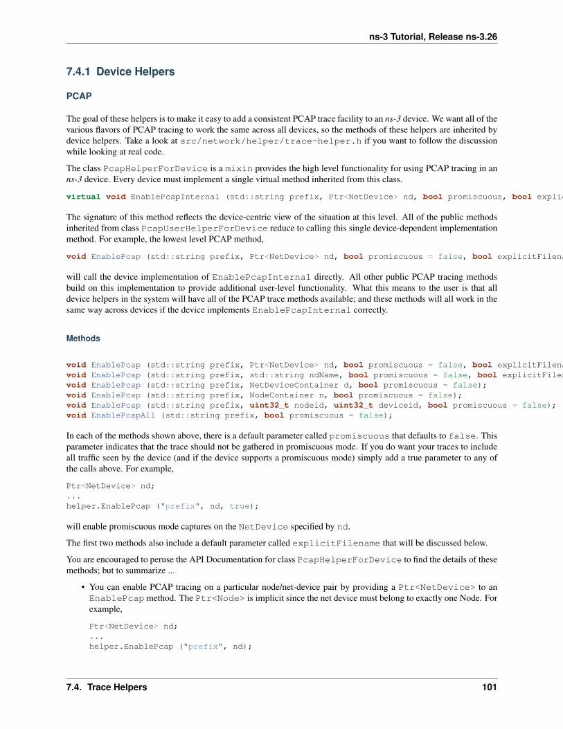
ns-3 Tutorial, Release ns-3.26
7.4.1 Device Helpers
PCAP
The goal of these helpers is to make it easy to add a consistent PCAP trace facility to an ns-3 device. We want all of thevarious flavors of PCAP tracing to work the same across all devices, so the methods of these helpers are inherited bydevice helpers. Take a look at src/network/helper/trace-helper.h if you want to follow the discussionwhile looking at real code.
The class PcapHelperForDevice is a mixin provides the high level functionality for using PCAP tracing in anns-3 device. Every device must implement a single virtual method inherited from this class.
virtual void EnablePcapInternal (std::string prefix, Ptr<NetDevice> nd, bool promiscuous, bool explicitFilename) = 0;
The signature of this method reflects the device-centric view of the situation at this level. All of the public methodsinherited from class PcapUserHelperForDevice reduce to calling this single device-dependent implementationmethod. For example, the lowest level PCAP method,
void EnablePcap (std::string prefix, Ptr<NetDevice> nd, bool promiscuous = false, bool explicitFilename = false);
will call the device implementation of EnablePcapInternal directly. All other public PCAP tracing methodsbuild on this implementation to provide additional user-level functionality. What this means to the user is that alldevice helpers in the system will have all of the PCAP trace methods available; and these methods will all work in thesame way across devices if the device implements EnablePcapInternal correctly.
Methods
void EnablePcap (std::string prefix, Ptr<NetDevice> nd, bool promiscuous = false, bool explicitFilename = false);void EnablePcap (std::string prefix, std::string ndName, bool promiscuous = false, bool explicitFilename = false);void EnablePcap (std::string prefix, NetDeviceContainer d, bool promiscuous = false);void EnablePcap (std::string prefix, NodeContainer n, bool promiscuous = false);void EnablePcap (std::string prefix, uint32_t nodeid, uint32_t deviceid, bool promiscuous = false);void EnablePcapAll (std::string prefix, bool promiscuous = false);
In each of the methods shown above, there is a default parameter called promiscuous that defaults to false. Thisparameter indicates that the trace should not be gathered in promiscuous mode. If you do want your traces to includeall traffic seen by the device (and if the device supports a promiscuous mode) simply add a true parameter to any ofthe calls above. For example,
Ptr<NetDevice> nd;...helper.EnablePcap ("prefix", nd, true);
will enable promiscuous mode captures on the NetDevice specified by nd.
The first two methods also include a default parameter called explicitFilename that will be discussed below.
You are encouraged to peruse the API Documentation for class PcapHelperForDevice to find the details of thesemethods; but to summarize ...
• You can enable PCAP tracing on a particular node/net-device pair by providing a Ptr<NetDevice> to anEnablePcap method. The Ptr<Node> is implicit since the net device must belong to exactly one Node. Forexample,
Ptr<NetDevice> nd;...helper.EnablePcap ("prefix", nd);
7.4. Trace Helpers 101

ns-3 Tutorial, Release ns-3.26
• You can enable PCAP tracing on a particular node/net-device pair by providing a std::string representingan object name service string to an EnablePcap method. The Ptr<NetDevice> is looked up from thename string. Again, the <Node> is implicit since the named net device must belong to exactly one Node. Forexample,
Names::Add ("server" ...);Names::Add ("server/eth0" ...);...helper.EnablePcap ("prefix", "server/ath0");
• You can enable PCAP tracing on a collection of node/net-device pairs by providing a NetDeviceContainer.For each NetDevice in the container the type is checked. For each device of the proper type (the same type asis managed by the device helper), tracing is enabled. Again, the <Node> is implicit since the found net devicemust belong to exactly one Node. For example,
NetDeviceContainer d = ...;...helper.EnablePcap ("prefix", d);
• You can enable PCAP tracing on a collection of node/net-device pairs by providing a NodeContainer. Foreach Node in the NodeContainer its attached NetDevices are iterated. For each NetDevice attachedto each Node in the container, the type of that device is checked. For each device of the proper type (the sametype as is managed by the device helper), tracing is enabled.
NodeContainer n;...helper.EnablePcap ("prefix", n);
• You can enable PCAP tracing on the basis of Node ID and device ID as well as with explicit Ptr. Each Nodein the system has an integer Node ID and each device connected to a Node has an integer device ID.
helper.EnablePcap ("prefix", 21, 1);
• Finally, you can enable PCAP tracing for all devices in the system, with the same type as that managed by thedevice helper.
helper.EnablePcapAll ("prefix");
Filenames
Implicit in the method descriptions above is the construction of a complete filename by the implementation method.By convention, PCAP traces in the ns-3 system are of the form <prefix>-<node id>-<device id>.pcap
As previously mentioned, every Node in the system will have a system-assigned Node id; and every device will havean interface index (also called a device id) relative to its node. By default, then, a PCAP trace file created as a resultof enabling tracing on the first device of Node 21 using the prefix “prefix” would be prefix-21-1.pcap.
You can always use the ns-3 object name service to make this more clear. For example, if you use the object nameservice to assign the name “server” to Node 21, the resulting PCAP trace file name will automatically become,prefix-server-1.pcap and if you also assign the name “eth0” to the device, your PCAP file name will au-tomatically pick this up and be called prefix-server-eth0.pcap.
Finally, two of the methods shown above,
void EnablePcap (std::string prefix, Ptr<NetDevice> nd, bool promiscuous = false, bool explicitFilename = false);void EnablePcap (std::string prefix, std::string ndName, bool promiscuous = false, bool explicitFilename = false);
102 Chapter 7. Tracing

ns-3 Tutorial, Release ns-3.26
have a default parameter called explicitFilename. When set to true, this parameter disables the automaticfilename completion mechanism and allows you to create an explicit filename. This option is only available in themethods which enable PCAP tracing on a single device.
For example, in order to arrange for a device helper to create a single promiscuous PCAP capture file of a specificname my-pcap-file.pcap on a given device, one could:
Ptr<NetDevice> nd;...helper.EnablePcap ("my-pcap-file.pcap", nd, true, true);
The first true parameter enables promiscuous mode traces and the second tells the helper to interpret the prefixparameter as a complete filename.
ASCII
The behavior of the ASCII trace helper mixin is substantially similar to the PCAP version. Take a look atsrc/network/helper/trace-helper.h if you want to follow the discussion while looking at real code.
The class AsciiTraceHelperForDevice adds the high level functionality for using ASCII tracing to a devicehelper class. As in the PCAP case, every device must implement a single virtual method inherited from the ASCIItrace mixin.
virtual void EnableAsciiInternal (Ptr<OutputStreamWrapper> stream,std::string prefix,Ptr<NetDevice> nd,bool explicitFilename) = 0;
The signature of this method reflects the device-centric view of the situation at this level; and also the fact that thehelper may be writing to a shared output stream. All of the public ASCII-trace-related methods inherited from classAsciiTraceHelperForDevice reduce to calling this single device- dependent implementation method. Forexample, the lowest level ascii trace methods,
void EnableAscii (std::string prefix, Ptr<NetDevice> nd, bool explicitFilename = false);void EnableAscii (Ptr<OutputStreamWrapper> stream, Ptr<NetDevice> nd);
will call the device implementation of EnableAsciiInternal directly, providing either a valid prefix or stream.All other public ASCII tracing methods will build on these low-level functions to provide additional user-levelfunctionality. What this means to the user is that all device helpers in the system will have all of the ASCIItrace methods available; and these methods will all work in the same way across devices if the devices implementEnablAsciiInternal correctly.
Methods
void EnableAscii (std::string prefix, Ptr<NetDevice> nd, bool explicitFilename = false);void EnableAscii (Ptr<OutputStreamWrapper> stream, Ptr<NetDevice> nd);
void EnableAscii (std::string prefix, std::string ndName, bool explicitFilename = false);void EnableAscii (Ptr<OutputStreamWrapper> stream, std::string ndName);
void EnableAscii (std::string prefix, NetDeviceContainer d);void EnableAscii (Ptr<OutputStreamWrapper> stream, NetDeviceContainer d);
void EnableAscii (std::string prefix, NodeContainer n);void EnableAscii (Ptr<OutputStreamWrapper> stream, NodeContainer n);
7.4. Trace Helpers 103

ns-3 Tutorial, Release ns-3.26
void EnableAsciiAll (std::string prefix);void EnableAsciiAll (Ptr<OutputStreamWrapper> stream);
void EnableAscii (std::string prefix, uint32_t nodeid, uint32_t deviceid, bool explicitFilename);void EnableAscii (Ptr<OutputStreamWrapper> stream, uint32_t nodeid, uint32_t deviceid);
You are encouraged to peruse the API Documentation for class AsciiTraceHelperForDevice to find the detailsof these methods; but to summarize ...
• There are twice as many methods available for ASCII tracing as there were for PCAP tracing. This is because,in addition to the PCAP-style model where traces from each unique node/device pair are written to a unique file,we support a model in which trace information for many node/device pairs is written to a common file. Thismeans that the <prefix>-<node>-<device> file name generation mechanism is replaced by a mechanism to referto a common file; and the number of API methods is doubled to allow all combinations.
• Just as in PCAP tracing, you can enable ASCII tracing on a particular (node, net-device) pair by providing aPtr<NetDevice> to an EnableAscii method. The Ptr<Node> is implicit since the net device mustbelong to exactly one Node. For example,
Ptr<NetDevice> nd;...helper.EnableAscii ("prefix", nd);
• The first four methods also include a default parameter called explicitFilename that operate similar toequivalent parameters in the PCAP case.
In this case, no trace contexts are written to the ASCII trace file since they would be redundant. The system willpick the file name to be created using the same rules as described in the PCAP section, except that the file willhave the suffix .tr instead of .pcap.
• If you want to enable ASCII tracing on more than one net device and have all traces sent to a single file, youcan do that as well by using an object to refer to a single file. We have already seen this in the “cwnd” exampleabove:
Ptr<NetDevice> nd1;Ptr<NetDevice> nd2;...Ptr<OutputStreamWrapper> stream = asciiTraceHelper.CreateFileStream ("trace-file-name.tr");...helper.EnableAscii (stream, nd1);helper.EnableAscii (stream, nd2);
In this case, trace contexts are written to the ASCII trace file since they are required to disambiguate traces fromthe two devices. Note that since the user is completely specifying the file name, the string should include the,tr suffix for consistency.
• You can enable ASCII tracing on a particular (node, net-device) pair by providing a std::string represent-ing an object name service string to an EnablePcap method. The Ptr<NetDevice> is looked up from thename string. Again, the <Node> is implicit since the named net device must belong to exactly one Node. Forexample,
Names::Add ("client" ...);Names::Add ("client/eth0" ...);Names::Add ("server" ...);Names::Add ("server/eth0" ...);...helper.EnableAscii ("prefix", "client/eth0");helper.EnableAscii ("prefix", "server/eth0");
104 Chapter 7. Tracing

ns-3 Tutorial, Release ns-3.26
This would result in two files named ``prefix-client-eth0.tr`` and``prefix-server-eth0.tr`` with traces for each device in therespective trace file. Since all of the ``EnableAscii`` functionsare overloaded to take a stream wrapper, you can use that form aswell::
Names::Add ("client" ...);Names::Add ("client/eth0" ...);Names::Add ("server" ...);Names::Add ("server/eth0" ...);...Ptr<OutputStreamWrapper> stream = asciiTraceHelper.CreateFileStream ("trace-file-name.tr");...helper.EnableAscii (stream, "client/eth0");helper.EnableAscii (stream, "server/eth0");
This would result in a single trace file called trace-file-name.tr that contains all of the trace events forboth devices. The events would be disambiguated by trace context strings.
• You can enable ASCII tracing on a collection of (node, net-device) pairs by providing aNetDeviceContainer. For each NetDevice in the container the type is checked. For each deviceof the proper type (the same type as is managed by the device helper), tracing is enabled. Again, the <Node>is implicit since the found net device must belong to exactly one Node. For example,
NetDeviceContainer d = ...;...helper.EnableAscii ("prefix", d);
This would result in a number of ASCII trace files being created,each of which follows the ``<prefix>-<node id>-<device id>.tr``convention.
Combining all of the traces into a single file is accomplished similarly to the examples above:
NetDeviceContainer d = ...;...Ptr<OutputStreamWrapper> stream = asciiTraceHelper.CreateFileStream ("trace-file-name.tr");...helper.EnableAscii (stream, d);
• You can enable ASCII tracing on a collection of (node, net-device) pairs by providing a NodeContainer. Foreach Node in the NodeContainer its attached NetDevices are iterated. For each NetDevice attachedto each Node in the container, the type of that device is checked. For each device of the proper type (the sametype as is managed by the device helper), tracing is enabled.
NodeContainer n;...helper.EnableAscii ("prefix", n);
This would result in a number of ASCII trace files being created, each of which follows the <prefix>-<nodeid>-<device id>.tr convention. Combining all of the traces into a single file is accomplished similarlyto the examples above.
• You can enable PCAP tracing on the basis of Node ID and device ID as well as with explicit Ptr. Each Nodein the system has an integer Node ID and each device connected to a Node has an integer device ID.
helper.EnableAscii ("prefix", 21, 1);
Of course, the traces can be combined into a single file as shown above.
7.4. Trace Helpers 105

ns-3 Tutorial, Release ns-3.26
• Finally, you can enable PCAP tracing for all devices in the system, with the same type as that managed by thedevice helper.
helper.EnableAsciiAll ("prefix");
This would result in a number of ASCII trace files being created, one for every device in the system of thetype managed by the helper. All of these files will follow the <prefix>-<node id>-<device id>.trconvention. Combining all of the traces into a single file is accomplished similarly to the examples above.
Filenames
Implicit in the prefix-style method descriptions above is the construction of the complete filenames by the implemen-tation method. By convention, ASCII traces in the ns-3 system are of the form <prefix>-<node id>-<deviceid>.tr
As previously mentioned, every Node in the system will have a system-assigned Node id; and every device will havean interface index (also called a device id) relative to its node. By default, then, an ASCII trace file created as a resultof enabling tracing on the first device of Node 21, using the prefix “prefix”, would be prefix-21-1.tr.
You can always use the ns-3 object name service to make this more clear. For example, if you use the object nameservice to assign the name “server” to Node 21, the resulting ASCII trace file name will automatically become,prefix-server-1.tr and if you also assign the name “eth0” to the device, your ASCII trace file name willautomatically pick this up and be called prefix-server-eth0.tr.
Several of the methods have a default parameter called explicitFilename. When set to true, this parameterdisables the automatic filename completion mechanism and allows you to create an explicit filename. This option isonly available in the methods which take a prefix and enable tracing on a single device.
7.4.2 Protocol Helpers
PCAP
The goal of these mixins is to make it easy to add a consistent PCAP trace facility to protocols. We want all of thevarious flavors of PCAP tracing to work the same across all protocols, so the methods of these helpers are inheritedby stack helpers. Take a look at src/network/helper/trace-helper.h if you want to follow the discussionwhile looking at real code.
In this section we will be illustrating the methods as applied to the protocol Ipv4. To specify traces in similarprotocols, just substitute the appropriate type. For example, use a Ptr<Ipv6> instead of a Ptr<Ipv4> and callEnablePcapIpv6 instead of EnablePcapIpv4.
The class PcapHelperForIpv4 provides the high level functionality for using PCAP tracing in the Ipv4 protocol.Each protocol helper enabling these methods must implement a single virtual method inherited from this class. Therewill be a separate implementation for Ipv6, for example, but the only difference will be in the method names andsignatures. Different method names are required to disambiguate class Ipv4 from Ipv6 which are both derived fromclass Object, and methods that share the same signature.
virtual void EnablePcapIpv4Internal (std::string prefix,Ptr<Ipv4> ipv4,uint32_t interface,bool explicitFilename) = 0;
The signature of this method reflects the protocol and interface-centric view of the situation at this level. All of thepublic methods inherited from class PcapHelperForIpv4 reduce to calling this single device-dependent imple-mentation method. For example, the lowest level PCAP method,
106 Chapter 7. Tracing

ns-3 Tutorial, Release ns-3.26
void EnablePcapIpv4 (std::string prefix, Ptr<Ipv4> ipv4, uint32_t interface, bool explicitFilename = false);
will call the device implementation of EnablePcapIpv4Internal directly. All other public PCAP tracing meth-ods build on this implementation to provide additional user-level functionality. What this means to the user is that allprotocol helpers in the system will have all of the PCAP trace methods available; and these methods will all work inthe same way across protocols if the helper implements EnablePcapIpv4Internal correctly.
Methods
These methods are designed to be in one-to-one correspondence with the Node- and NetDevice- centric versions ofthe device versions. Instead of Node and NetDevice pair constraints, we use protocol and interface constraints.
Note that just like in the device version, there are six methods:
void EnablePcapIpv4 (std::string prefix, Ptr<Ipv4> ipv4, uint32_t interface, bool explicitFilename = false);void EnablePcapIpv4 (std::string prefix, std::string ipv4Name, uint32_t interface, bool explicitFilename = false);void EnablePcapIpv4 (std::string prefix, Ipv4InterfaceContainer c);void EnablePcapIpv4 (std::string prefix, NodeContainer n);void EnablePcapIpv4 (std::string prefix, uint32_t nodeid, uint32_t interface, bool explicitFilename);void EnablePcapIpv4All (std::string prefix);
You are encouraged to peruse the API Documentation for class PcapHelperForIpv4 to find the details of thesemethods; but to summarize ...
• You can enable PCAP tracing on a particular protocol/interface pair by providing a Ptr<Ipv4> andinterface to an EnablePcap method. For example,
Ptr<Ipv4> ipv4 = node->GetObject<Ipv4> ();...helper.EnablePcapIpv4 ("prefix", ipv4, 0);
• You can enable PCAP tracing on a particular node/net-device pair by providing a std::string representingan object name service string to an EnablePcapmethod. The Ptr<Ipv4> is looked up from the name string.For example,
Names::Add ("serverIPv4" ...);...helper.EnablePcapIpv4 ("prefix", "serverIpv4", 1);
• You can enable PCAP tracing on a collection of protocol/interface pairs by providing anIpv4InterfaceContainer. For each Ipv4 / interface pair in the container the protocol type ischecked. For each protocol of the proper type (the same type as is managed by the device helper), tracing isenabled for the corresponding interface. For example,
NodeContainer nodes;...NetDeviceContainer devices = deviceHelper.Install (nodes);...Ipv4AddressHelper ipv4;ipv4.SetBase ("10.1.1.0", "255.255.255.0");Ipv4InterfaceContainer interfaces = ipv4.Assign (devices);...helper.EnablePcapIpv4 ("prefix", interfaces);
• You can enable PCAP tracing on a collection of protocol/interface pairs by providing a NodeContainer. Foreach Node in the NodeContainer the appropriate protocol is found. For each protocol, its interfaces areenumerated and tracing is enabled on the resulting pairs. For example,
7.4. Trace Helpers 107

ns-3 Tutorial, Release ns-3.26
NodeContainer n;...helper.EnablePcapIpv4 ("prefix", n);
• You can enable PCAP tracing on the basis of Node ID and interface as well. In this case, the node-id is translatedto a Ptr<Node> and the appropriate protocol is looked up in the node. The resulting protocol and interface areused to specify the resulting trace source.
helper.EnablePcapIpv4 ("prefix", 21, 1);
• Finally, you can enable PCAP tracing for all interfaces in the system, with associated protocol being the sametype as that managed by the device helper.
helper.EnablePcapIpv4All ("prefix");
Filenames
Implicit in all of the method descriptions above is the construction of the complete filenames by the implementationmethod. By convention, PCAP traces taken for devices in the ns-3 system are of the form “<prefix>-<node id>-<deviceid>.pcap”. In the case of protocol traces, there is a one-to-one correspondence between protocols and Nodes. This isbecause protocol Objects are aggregated to Node Objects. Since there is no global protocol id in the system, weuse the corresponding Node id in file naming. Therefore there is a possibility for file name collisions in automaticallychosen trace file names. For this reason, the file name convention is changed for protocol traces.
As previously mentioned, every Node in the system will have a system-assigned Node id. Since there is a one-to-onecorrespondence between protocol instances and Node instances we use the Node id. Each interface has an interfaceid relative to its protocol. We use the convention “<prefix>-n<node id>-i<interface id>.pcap” for trace file naming inprotocol helpers.
Therefore, by default, a PCAP trace file created as a result of enabling tracing on interface 1 of the Ipv4 protocol ofNode 21 using the prefix “prefix” would be “prefix-n21-i1.pcap”.
You can always use the ns-3 object name service to make this more clear. For example, if you use the object nameservice to assign the name “serverIpv4” to the Ptr<Ipv4> on Node 21, the resulting PCAP trace file name will auto-matically become, “prefix-nserverIpv4-i1.pcap”.
Several of the methods have a default parameter called explicitFilename. When set to true, this parameterdisables the automatic filename completion mechanism and allows you to create an explicit filename. This option isonly available in the methods which take a prefix and enable tracing on a single device.
ASCII
The behavior of the ASCII trace helpers is substantially similar to the PCAP case. Take a look atsrc/network/helper/trace-helper.h if you want to follow the discussion while looking at real code.
In this section we will be illustrating the methods as applied to the protocol Ipv4. To specify traces in similarprotocols, just substitute the appropriate type. For example, use a Ptr<Ipv6> instead of a Ptr<Ipv4> and callEnableAsciiIpv6 instead of EnableAsciiIpv4.
The class AsciiTraceHelperForIpv4 adds the high level functionality for using ASCII tracing to a protocolhelper. Each protocol that enables these methods must implement a single virtual method inherited from this class.
virtual void EnableAsciiIpv4Internal (Ptr<OutputStreamWrapper> stream,std::string prefix,Ptr<Ipv4> ipv4,uint32_t interface,bool explicitFilename) = 0;
108 Chapter 7. Tracing

ns-3 Tutorial, Release ns-3.26
The signature of this method reflects the protocol- and interface-centric view of the situation at this level; and alsothe fact that the helper may be writing to a shared output stream. All of the public methods inherited from classPcapAndAsciiTraceHelperForIpv4 reduce to calling this single device- dependent implementation method.For example, the lowest level ASCII trace methods,
void EnableAsciiIpv4 (std::string prefix, Ptr<Ipv4> ipv4, uint32_t interface, bool explicitFilename = false);void EnableAsciiIpv4 (Ptr<OutputStreamWrapper> stream, Ptr<Ipv4> ipv4, uint32_t interface);
will call the device implementation of EnableAsciiIpv4Internal directly, providing either the prefix or thestream. All other public ASCII tracing methods will build on these low-level functions to provide additional user-level functionality. What this means to the user is that all device helpers in the system will have all of the ASCIItrace methods available; and these methods will all work in the same way across protocols if the protocols implementEnablAsciiIpv4Internal correctly.
Methods
void EnableAsciiIpv4 (std::string prefix, Ptr<Ipv4> ipv4, uint32_t interface, bool explicitFilename = false);void EnableAsciiIpv4 (Ptr<OutputStreamWrapper> stream, Ptr<Ipv4> ipv4, uint32_t interface);
void EnableAsciiIpv4 (std::string prefix, std::string ipv4Name, uint32_t interface, bool explicitFilename = false);void EnableAsciiIpv4 (Ptr<OutputStreamWrapper> stream, std::string ipv4Name, uint32_t interface);
void EnableAsciiIpv4 (std::string prefix, Ipv4InterfaceContainer c);void EnableAsciiIpv4 (Ptr<OutputStreamWrapper> stream, Ipv4InterfaceContainer c);
void EnableAsciiIpv4 (std::string prefix, NodeContainer n);void EnableAsciiIpv4 (Ptr<OutputStreamWrapper> stream, NodeContainer n);
void EnableAsciiIpv4All (std::string prefix);void EnableAsciiIpv4All (Ptr<OutputStreamWrapper> stream);
void EnableAsciiIpv4 (std::string prefix, uint32_t nodeid, uint32_t deviceid, bool explicitFilename);void EnableAsciiIpv4 (Ptr<OutputStreamWrapper> stream, uint32_t nodeid, uint32_t interface);
You are encouraged to peruse the API Documentation for class PcapAndAsciiHelperForIpv4 to find the detailsof these methods; but to summarize ...
• There are twice as many methods available for ASCII tracing as there were for PCAP tracing. This is because, inaddition to the PCAP-style model where traces from each unique protocol/interface pair are written to a uniquefile, we support a model in which trace information for many protocol/interface pairs is written to a commonfile. This means that the <prefix>-n<node id>-<interface> file name generation mechanism is replaced by amechanism to refer to a common file; and the number of API methods is doubled to allow all combinations.
• Just as in PCAP tracing, you can enable ASCII tracing on a particular protocol/interface pair by providing aPtr<Ipv4> and an interface to an EnableAscii method. For example,
Ptr<Ipv4> ipv4;...helper.EnableAsciiIpv4 ("prefix", ipv4, 1);
In this case, no trace contexts are written to the ASCII trace file since they would be redundant. The system willpick the file name to be created using the same rules as described in the PCAP section, except that the file willhave the suffix ”.tr” instead of ”.pcap”.
• If you want to enable ASCII tracing on more than one interface and have all traces sent to a single file, youcan do that as well by using an object to refer to a single file. We have already something similar to this in the“cwnd” example above:
7.4. Trace Helpers 109

ns-3 Tutorial, Release ns-3.26
Ptr<Ipv4> protocol1 = node1->GetObject<Ipv4> ();Ptr<Ipv4> protocol2 = node2->GetObject<Ipv4> ();...Ptr<OutputStreamWrapper> stream = asciiTraceHelper.CreateFileStream ("trace-file-name.tr");...helper.EnableAsciiIpv4 (stream, protocol1, 1);helper.EnableAsciiIpv4 (stream, protocol2, 1);
In this case, trace contexts are written to the ASCII trace file since they are required to disambiguate traces fromthe two interfaces. Note that since the user is completely specifying the file name, the string should include the”,tr” for consistency.
• You can enable ASCII tracing on a particular protocol by providing a std::string representing an objectname service string to an EnablePcap method. The Ptr<Ipv4> is looked up from the name string. The<Node> in the resulting filenames is implicit since there is a one-to-one correspondence between protocolinstances and nodes, For example,
Names::Add ("node1Ipv4" ...);Names::Add ("node2Ipv4" ...);...helper.EnableAsciiIpv4 ("prefix", "node1Ipv4", 1);helper.EnableAsciiIpv4 ("prefix", "node2Ipv4", 1);
This would result in two files named “prefix-nnode1Ipv4-i1.tr” and “prefix-nnode2Ipv4-i1.tr” with traces foreach interface in the respective trace file. Since all of the EnableAscii functions are overloaded to take a streamwrapper, you can use that form as well:
Names::Add ("node1Ipv4" ...);Names::Add ("node2Ipv4" ...);...Ptr<OutputStreamWrapper> stream = asciiTraceHelper.CreateFileStream ("trace-file-name.tr");...helper.EnableAsciiIpv4 (stream, "node1Ipv4", 1);helper.EnableAsciiIpv4 (stream, "node2Ipv4", 1);
This would result in a single trace file called “trace-file-name.tr” that contains all of the trace events for bothinterfaces. The events would be disambiguated by trace context strings.
• You can enable ASCII tracing on a collection of protocol/interface pairs by providing anIpv4InterfaceContainer. For each protocol of the proper type (the same type as is managed bythe device helper), tracing is enabled for the corresponding interface. Again, the <Node> is implicit since thereis a one-to-one correspondence between each protocol and its node. For example,
NodeContainer nodes;...NetDeviceContainer devices = deviceHelper.Install (nodes);...Ipv4AddressHelper ipv4;ipv4.SetBase ("10.1.1.0", "255.255.255.0");Ipv4InterfaceContainer interfaces = ipv4.Assign (devices);......helper.EnableAsciiIpv4 ("prefix", interfaces);
This would result in a number of ASCII trace files being created, each of which follows the <prefix>-n<nodeid>-i<interface>.tr convention. Combining all of the traces into a single file is accomplished similarly to theexamples above:
110 Chapter 7. Tracing

ns-3 Tutorial, Release ns-3.26
NodeContainer nodes;...NetDeviceContainer devices = deviceHelper.Install (nodes);...Ipv4AddressHelper ipv4;ipv4.SetBase ("10.1.1.0", "255.255.255.0");Ipv4InterfaceContainer interfaces = ipv4.Assign (devices);...Ptr<OutputStreamWrapper> stream = asciiTraceHelper.CreateFileStream ("trace-file-name.tr");...helper.EnableAsciiIpv4 (stream, interfaces);
• You can enable ASCII tracing on a collection of protocol/interface pairs by providing a NodeContainer.For each Node in the NodeContainer the appropriate protocol is found. For each protocol, its interfaces areenumerated and tracing is enabled on the resulting pairs. For example,
NodeContainer n;...helper.EnableAsciiIpv4 ("prefix", n);
This would result in a number of ASCII trace files being created, each of which follows the <prefix>-<nodeid>-<device id>.tr convention. Combining all of the traces into a single file is accomplished similarly to theexamples above.
• You can enable PCAP tracing on the basis of Node ID and device ID as well. In this case, the node-id istranslated to a Ptr<Node> and the appropriate protocol is looked up in the node. The resulting protocol andinterface are used to specify the resulting trace source.
helper.EnableAsciiIpv4 ("prefix", 21, 1);
Of course, the traces can be combined into a single file as shown above.
• Finally, you can enable ASCII tracing for all interfaces in the system, with associated protocol being the sametype as that managed by the device helper.
helper.EnableAsciiIpv4All ("prefix");
This would result in a number of ASCII trace files being created, one for every interface in the system related to aprotocol of the type managed by the helper. All of these files will follow the <prefix>-n<node id>-i<interface.trconvention. Combining all of the traces into a single file is accomplished similarly to the examples above.
Filenames
Implicit in the prefix-style method descriptions above is the construction of the complete filenames by the implemen-tation method. By convention, ASCII traces in the ns-3 system are of the form “<prefix>-<node id>-<device id>.tr”
As previously mentioned, every Node in the system will have a system-assigned Node id. Since there is a one-to-onecorrespondence between protocols and nodes we use to node-id to identify the protocol identity. Every interface on agiven protocol will have an interface index (also called simply an interface) relative to its protocol. By default, then,an ASCII trace file created as a result of enabling tracing on the first device of Node 21, using the prefix “prefix”,would be “prefix-n21-i1.tr”. Use the prefix to disambiguate multiple protocols per node.
You can always use the ns-3 object name service to make this more clear. For example, if you use the object nameservice to assign the name “serverIpv4” to the protocol on Node 21, and also specify interface one, the resulting ASCIItrace file name will automatically become, “prefix-nserverIpv4-1.tr”.
Several of the methods have a default parameter called explicitFilename. When set to true, this parameterdisables the automatic filename completion mechanism and allows you to create an explicit filename. This option is
7.4. Trace Helpers 111

ns-3 Tutorial, Release ns-3.26
only available in the methods which take a prefix and enable tracing on a single device.
7.5 Summary
ns-3 includes an extremely rich environment allowing users at several levels to customize the kinds of information thatcan be extracted from simulations.
There are high-level helper functions that allow users to simply control the collection of pre-defined outputs to a finegranularity. There are mid-level helper functions to allow more sophisticated users to customize how information isextracted and saved; and there are low-level core functions to allow expert users to alter the system to present new andpreviously unexported information in a way that will be immediately accessible to users at higher levels.
This is a very comprehensive system, and we realize that it is a lot to digest, especially for new users or those notintimately familiar with C++ and its idioms. We do consider the tracing system a very important part of ns-3 and sorecommend becoming as familiar as possible with it. It is probably the case that understanding the rest of the ns-3system will be quite simple once you have mastered the tracing system
112 Chapter 7. Tracing

CHAPTER
EIGHT
DATA COLLECTION
Our final tutorial chapter introduces some components that were added to ns-3 in version 3.18, and that are still underdevelopment. This tutorial section is also a work-in-progress.
8.1 Motivation
One of the main points of running simulations is to generate output data, either for research purposes or simply to learnabout the system. In the previous chapter, we introduced the tracing subsystem and the example sixth.cc. fromwhich PCAP or ASCII trace files are generated. These traces are valuable for data analysis using a variety of externaltools, and for many users, such output data is a preferred means of gathering data (for analysis by external tools).
However, there are also use cases for more than trace file generation, including the following:
• generation of data that does not map well to PCAP or ASCII traces, such as non-packet data (e.g. protocol statemachine transitions),
• large simulations for which the disk I/O requirements for generating trace files is prohibitive or cumbersome,and
• the need for online data reduction or computation, during the course of the simulation. A good example of thisis to define a termination condition for the simulation, to tell it when to stop when it has received enough datato form a narrow-enough confidence interval around the estimate of some parameter.
The ns-3 data collection framework is designed to provide these additional capabilities beyond trace-based output.We recommend that the reader interested in this topic consult the ns-3 Manual for a more detailed treatment of thisframework; here, we summarize with an example program some of the developing capabilities.
8.2 Example Code
The tutorial example examples/tutorial/seventh.cc resembles the sixth.cc example we previouslyreviewed, except for a few changes. First, it has been enabled for IPv6 support with a command-line option:
CommandLine cmd;cmd.AddValue ("useIpv6", "Use Ipv6", useV6);cmd.Parse (argc, argv);
If the user specifies useIpv6, option, the program will be run using IPv6 instead of IPv4. The help option, availableon all ns-3 programs that support the CommandLine object as shown above, can be invoked as follows (please notethe use of double quotes):
./waf --run "seventh --help"
113

ns-3 Tutorial, Release ns-3.26
which produces:
ns3-dev-seventh-debug [Program Arguments] [General Arguments]
Program Arguments:--useIpv6: Use Ipv6 [false]
General Arguments:--PrintGlobals: Print the list of globals.--PrintGroups: Print the list of groups.--PrintGroup=[group]: Print all TypeIds of group.--PrintTypeIds: Print all TypeIds.--PrintAttributes=[typeid]: Print all attributes of typeid.--PrintHelp: Print this help message.
This default (use of IPv4, since useIpv6 is false) can be changed by toggling the boolean value as follows:
./waf --run "seventh --useIpv6=1"
and have a look at the pcap generated, such as with tcpdump:
tcpdump -r seventh.pcap -nn -tt
This has been a short digression into IPv6 support and the command line, which was also in-troduced earlier in this tutorial. For a dedicated example of command line usage, please seesrc/core/examples/command-line-example.cc.
Now back to data collection. In the examples/tutorial/ directory, type the following command: diff -usixth.cc seventh.cc, and examine some of the new lines of this diff:
+ std::string probeType;+ std::string tracePath;+ if (useV6 == false)+ {
...+ probeType = "ns3::Ipv4PacketProbe";+ tracePath = "/NodeList/*/$ns3::Ipv4L3Protocol/Tx";+ }+ else+ {
...+ probeType = "ns3::Ipv6PacketProbe";+ tracePath = "/NodeList/*/$ns3::Ipv6L3Protocol/Tx";+ }...
+ // Use GnuplotHelper to plot the packet byte count over time+ GnuplotHelper plotHelper;++ // Configure the plot. The first argument is the file name prefix+ // for the output files generated. The second, third, and fourth+ // arguments are, respectively, the plot title, x-axis, and y-axis labels+ plotHelper.ConfigurePlot ("seventh-packet-byte-count",+ "Packet Byte Count vs. Time",+ "Time (Seconds)",+ "Packet Byte Count");++ // Specify the probe type, trace source path (in configuration namespace), and+ // probe output trace source ("OutputBytes") to plot. The fourth argument+ // specifies the name of the data series label on the plot. The last+ // argument formats the plot by specifying where the key should be placed.
114 Chapter 8. Data Collection

ns-3 Tutorial, Release ns-3.26
+ plotHelper.PlotProbe (probeType,+ tracePath,+ "OutputBytes",+ "Packet Byte Count",+ GnuplotAggregator::KEY_BELOW);++ // Use FileHelper to write out the packet byte count over time+ FileHelper fileHelper;++ // Configure the file to be written, and the formatting of output data.+ fileHelper.ConfigureFile ("seventh-packet-byte-count",+ FileAggregator::FORMATTED);++ // Set the labels for this formatted output file.+ fileHelper.Set2dFormat ("Time (Seconds) = %.3e\tPacket Byte Count = %.0f");++ // Specify the probe type, probe path (in configuration namespace), and+ // probe output trace source ("OutputBytes") to write.+ fileHelper.WriteProbe (probeType,+ tracePath,+ "OutputBytes");+
Simulator::Stop (Seconds (20));Simulator::Run ();Simulator::Destroy ();
The careful reader will have noticed, when testing the IPv6 command line attribute above, that seventh.cc hadcreated a number of new output files:
seventh-packet-byte-count-0.txtseventh-packet-byte-count-1.txtseventh-packet-byte-count.datseventh-packet-byte-count.pltseventh-packet-byte-count.pngseventh-packet-byte-count.sh
These were created by the additional statements introduced above; in particular, by a GnuplotHelper and a FileHelper.This data was produced by hooking the data collection components to ns-3 trace sources, and marshaling the data intoa formatted gnuplot and into a formatted text file. In the next sections, we’ll review each of these.
8.3 GnuplotHelper
The GnuplotHelper is an ns-3 helper object aimed at the production of gnuplot plots with as few statements aspossible, for common cases. It hooks ns-3 trace sources with data types supported by the data collection system. Notall ns-3 trace sources data types are supported, but many of the common trace types are, including TracedValues withplain old data (POD) types.
Let’s look at the output produced by this helper:
seventh-packet-byte-count.datseventh-packet-byte-count.pltseventh-packet-byte-count.sh
The first is a gnuplot data file with a series of space-delimited timestamps and packet byte counts. We’llcover how this particular data output was configured below, but let’s continue with the output files. Thefile seventh-packet-byte-count.plt is a gnuplot plot file, that can be opened from within gnuplot.
8.3. GnuplotHelper 115

ns-3 Tutorial, Release ns-3.26
Readers who understand gnuplot syntax can see that this will produce a formatted output PNG file namedseventh-packet-byte-count.png. Finally, a small shell script seventh-packet-byte-count.shruns this plot file through gnuplot to produce the desired PNG (which can be viewed in an image editor); that is, thecommand:
sh seventh-packet-byte-count.sh
will yield seventh-packet-byte-count.png. Why wasn’t this PNG produced in the first place? The answeris that by providing the plt file, the user can hand-configure the result if desired, before producing the PNG.
The PNG image title states that this plot is a plot of “Packet Byte Count vs. Time”, and that it is plotting the probeddata corresponding to the trace source path:
/NodeList/*/$ns3::Ipv6L3Protocol/Tx
Note the wild-card in the trace path. In summary, what this plot is capturing is the plot of packet bytes observed at thetransmit trace source of the Ipv6L3Protocol object; largely 596-byte TCP segments in one direction, and 60-byte TCPacks in the other (two node trace sources were matched by this trace source).
How was this configured? A few statements need to be provided. First, the GnuplotHelper object must be declaredand configured:
+ // Use GnuplotHelper to plot the packet byte count over time+ GnuplotHelper plotHelper;++ // Configure the plot. The first argument is the file name prefix+ // for the output files generated. The second, third, and fourth+ // arguments are, respectively, the plot title, x-axis, and y-axis labels+ plotHelper.ConfigurePlot ("seventh-packet-byte-count",+ "Packet Byte Count vs. Time",+ "Time (Seconds)",+ "Packet Byte Count");
To this point, an empty plot has been configured. The filename prefix is the first argument, the plot title is the second,the x-axis label the third, and the y-axis label the fourth argument.
The next step is to configure the data, and here is where the trace source is hooked. First, note above in the programwe declared a few variables for later use:
+ std::string probeType;+ std::string tracePath;+ probeType = "ns3::Ipv6PacketProbe";+ tracePath = "/NodeList/*/$ns3::Ipv6L3Protocol/Tx";
We use them here:
+ // Specify the probe type, trace source path (in configuration namespace), and+ // probe output trace source ("OutputBytes") to plot. The fourth argument+ // specifies the name of the data series label on the plot. The last+ // argument formats the plot by specifying where the key should be placed.+ plotHelper.PlotProbe (probeType,+ tracePath,+ "OutputBytes",+ "Packet Byte Count",+ GnuplotAggregator::KEY_BELOW);
The first two arguments are the name of the probe type and the trace source path. These two are prob-ably the hardest to determine when you try to use this framework to plot other traces. The probe tracehere is the Tx trace source of class Ipv6L3Protocol. When we examine this class implementation(src/internet/model/ipv6-l3-protocol.cc) we can observe:
116 Chapter 8. Data Collection

ns-3 Tutorial, Release ns-3.26
.AddTraceSource ("Tx", "Send IPv6 packet to outgoing interface.",MakeTraceSourceAccessor (&Ipv6L3Protocol::m_txTrace))
This says that Tx is a name for variable m_txTrace, which has a declaration of:
/*** \brief Callback to trace TX (transmission) packets.
*/TracedCallback<Ptr<const Packet>, Ptr<Ipv6>, uint32_t> m_txTrace;
It turns out that this specific trace source signature is supported by a Probe class (what we need here) of classIpv6PacketProbe. See the files src/internet/model/ipv6-packet-probe.{h,cc}.
So, in the PlotProbe statement above, we see that the statement is hooking the trace source (identified by path string)with a matching ns-3 Probe type of Ipv6PacketProbe. If we did not support this probe type (matching tracesource signature), we could have not used this statement (although some more complicated lower-level statementscould have been used, as described in the manual).
The Ipv6PacketProbe exports, itself, some trace sources that extract the data out of the probed Packet object:
TypeIdIpv6PacketProbe::GetTypeId (){
static TypeId tid = TypeId ("ns3::Ipv6PacketProbe").SetParent<Probe> ().SetGroupName ("Stats").AddConstructor<Ipv6PacketProbe> ().AddTraceSource ( "Output",
"The packet plus its IPv6 object and interface that serve as the output for this probe",MakeTraceSourceAccessor (&Ipv6PacketProbe::m_output))
.AddTraceSource ( "OutputBytes","The number of bytes in the packet",MakeTraceSourceAccessor (&Ipv6PacketProbe::m_outputBytes))
;return tid;
}
The third argument of our PlotProbe statement specifies that we are interested in the number of bytes in this packet;specifically, the “OutputBytes” trace source of Ipv6PacketProbe. Finally, the last two arguments of the statementprovide the plot legend for this data series (“Packet Byte Count”), and an optional gnuplot formatting statement(GnuplotAggregator::KEY_BELOW) that we want the plot key to be inserted below the plot. Other options includeNO_KEY, KEY_INSIDE, and KEY_ABOVE.
8.4 Supported Trace Types
The following traced values are supported with Probes as of this writing:
TracedValue type Probe type Filedouble DoubleProbe stats/model/double-probe.huint8_t Uinteger8Probe stats/model/uinteger-8-probe.huint16_t Uinteger16Probe stats/model/uinteger-16-probe.huint32_t Uinteger32Probe stats/model/uinteger-32-probe.hbool BooleanProbe stats/model/uinteger-16-probe.hns3::Time TimeProbe stats/model/time-probe.h
The following TraceSource types are supported by Probes as of this writing:
8.4. Supported Trace Types 117

ns-3 Tutorial, Release ns-3.26
TracedSource type Probe type Probeoutputs
File
Ptr<const Packet> PacketProbe Output-Bytes
network/utils/packet-probe.h
Ptr<const Packet>,Ptr<Ipv4>, uint32_t
Ipv4PacketProbe Output-Bytes
internet/model/ipv4-packet-probe.h
Ptr<const Packet>,Ptr<Ipv6>, uint32_t
Ipv6PacketProbe Output-Bytes
internet/model/ipv6-packet-probe.h
Ptr<const Packet>,Ptr<Ipv6>, uint32_t
Ipv6PacketProbe Output-Bytes
internet/model/ipv6-packet-probe.h
Ptr<const Packet>, constAddress&
ApplicationPack-etProbe
Output-Bytes
applications/model/application-packet-probe.h
As can be seen, only a few trace sources are supported, and they are all oriented towards outputting the Packet size (inbytes). However, most of the fundamental data types available as TracedValues can be supported with these helpers.
8.5 FileHelper
The FileHelper class is just a variation of the previous GnuplotHelper example. The example program providesformatted output of the same timestamped data, such as follows:
Time (Seconds) = 9.312e+00 Packet Byte Count = 596Time (Seconds) = 9.312e+00 Packet Byte Count = 564
Two files are provided, one for node “0” and one for node “1” as can be seen in the filenames. Let’s look at the codepiece-by-piece:
+ // Use FileHelper to write out the packet byte count over time+ FileHelper fileHelper;++ // Configure the file to be written, and the formatting of output data.+ fileHelper.ConfigureFile ("seventh-packet-byte-count",+ FileAggregator::FORMATTED);
The file helper file prefix is the first argument, and a format specifier is next. Some other options for formatting includeSPACE_SEPARATED, COMMA_SEPARATED, and TAB_SEPARATED. Users are able to change the formatting (ifFORMATTED is specified) with a format string such as follows:
++ // Set the labels for this formatted output file.+ fileHelper.Set2dFormat ("Time (Seconds) = %.3e\tPacket Byte Count = %.0f");
Finally, the trace source of interest must be hooked. Again, the probeType and tracePath variables in this example areused, and the probe’s output trace source “OutputBytes” is hooked:
++ // Specify the probe type, trace source path (in configuration namespace), and+ // probe output trace source ("OutputBytes") to write.+ fileHelper.WriteProbe (probeType,+ tracePath,+ "OutputBytes");+
The wildcard fields in this trace source specifier match two trace sources. Unlike the GnuplotHelper example, in whichtwo data series were overlaid on the same plot, here, two separate files are written to disk.
118 Chapter 8. Data Collection

ns-3 Tutorial, Release ns-3.26
8.6 Summary
Data collection support is new as of ns-3.18, and basic support for providing time series output has been added. Thebasic pattern described above may be replicated within the scope of support of the existing probes and trace sources.More capabilities including statistics processing will be added in future releases.
8.6. Summary 119

ns-3 Tutorial, Release ns-3.26
120 Chapter 8. Data Collection

CHAPTER
NINE
CONCLUSION
9.1 Futures
This document is intended as a living document. We hope and expect it to grow over time to cover more and more ofthe nuts and bolts of ns-3.
Writing manual and tutorial chapters is not something we all get excited about, but it is very important to the project.If you are an expert in one of these areas, please consider contributing to ns-3 by providing one of these chapters; orany other chapter you may think is important.
9.2 Closing
ns-3 is a large and complicated system. It is impossible to cover all of the things you will need to know in one smalltutorial. Readers who want to learn more are encouraged to read the following additional documentation:
• The ns-3 manual
• The ns-3 model library documentation
• The ns-3 Doxygen (API documentation)
• The ns-3 wiki
– The ns-3 development team.
121