NPS/002/017 Technical Specification for 66 kV and 132 kV ...132 kV accessories shall be rated at a...
21
Document reference NPS/002/017 Document Type Section Level Version:- 4.0 Date of Issue:- October 2016 Page 1 of 21 CAUTION! - This document may be out of date if printed NPS/002/017 – Technical Specification for 66 kV and 132 kV Cable Accessories 1. Purpose The purpose of this document is to detail the technical requirements of 66 kV and 132 kV cable accessories for use on the Northern Powergrid (the Company) distribution network. This document supersedes the following document, all copies of which should be destroyed. Ref Version Date Title NPS/002/017 4.0 April 2010 Technical Specification for 66 kV and 132 kV Cable Accessories 2. Scope This specification details the technical requirements for 66 kV and 132 kV cable accessories. This includes XLPE to XLPE straight joints, transition joints and terminations for use on the Company’s distribution network. Any technical documents referenced in this specification refer to the latest versions of the relevant International Standards, British Standards (BS) and Energy Networks Association (ENA) Standards current at the time of supply. Service failures have been experienced on terminations due to longitudinal shrinkage of cable oversheath material and disturbance to the lead sheath, moisture seals and earth connections. All accessories shall, as far as is reasonably practicable, accommodate or prevent movement of cable components occurring as a result of cable sheath retraction. The following appendices form part of this technical specification: Appendix 1 – Typical cable types and sizes, Appendix 2 – Additional tests for terminations, Appendix 3 – Logistical requirements, Appendix 4 – Self certification conformance declaration, Appendix 5 – Addendum to supplier requirements, Appendix 6 – Pre-commission testing, routine inspection and maintenance requirements, and, Appendix 7 – Technical information checklist.
Transcript of NPS/002/017 Technical Specification for 66 kV and 132 kV ...132 kV accessories shall be rated at a...

Document reference NPS/002/017 Document Type Section Level
Version:- 4.0 Date of Issue:- October 2016 Page 1 of 21
CAUTION! - This document may be out of date if printed
NPS/002/017 – Technical Specification for 66 kV and 132 kV Cable Accessories
1. Purpose
The purpose of this document is to detail the technical requirements of 66 kV and 132 kV cable accessories for use on the Northern Powergrid (the Company) distribution network.
This document supersedes the following document, all copies of which should be destroyed.
Ref Version Date Title
NPS/002/017 4.0 April 2010 Technical Specification for 66 kV and 132 kV Cable Accessories
2. Scope
This specification details the technical requirements for 66 kV and 132 kV cable accessories. This includes XLPE to XLPE straight joints, transition joints and terminations for use on the Company’s distribution network.
Any technical documents referenced in this specification refer to the latest versions of the relevant International Standards, British Standards (BS) and Energy Networks Association (ENA) Standards current at the time of supply.
Service failures have been experienced on terminations due to longitudinal shrinkage of cable oversheath material and disturbance to the lead sheath, moisture seals and earth connections. All accessories shall, as far as is reasonably practicable, accommodate or prevent movement of cable components occurring as a result of cable sheath retraction.
The following appendices form part of this technical specification:
Appendix 1 – Typical cable types and sizes,
Appendix 2 – Additional tests for terminations,
Appendix 3 – Logistical requirements,
Appendix 4 – Self certification conformance declaration,
Appendix 5 – Addendum to supplier requirements,
Appendix 6 – Pre-commission testing, routine inspection and maintenance requirements, and,
Appendix 7 – Technical information checklist.

Document reference NPS/002/017 Document Type Section Level
Version:- 4.0 Date of Issue:- October 2016 Page 2 of 21
CAUTION! - This document may be out of date if printed
2.1 Contents
1. Purpose .......................................................................................................................................................................... 1
2. Scope ............................................................................................................................................................................. 1
1.1. 2.1 Contents ................................................................................................................................................................. 2
3. Technical Requirements ................................................................................................................................................. 3
3.1. Conditions of operation ............................................................................................................................................... 3
3.2. Joints ............................................................................................................................................................................ 3
3.2.1. General..................................................................................................................................................................... 3
3.2.2. Single-core XLPE to XLPE straight joints ................................................................................................................... 3
3.2.3. Transition joints (single-core XLPE to single-core and 3-core fluid filled, or gas filled cables) ................................ 3
3.2.4. Oil filled joints (single-core and 3-core fluid filled) .................................................................................................. 4
3.2.5. Gas filled joints (single-core and 3-core gas filled) .................................................................................................. 4
3.3. Terminations ................................................................................................................................................................ 4
3.3.1. General..................................................................................................................................................................... 4
3.3.2. Indoor and outdoor terminations ............................................................................................................................ 4
3.3.3. Gas insulated switchgear (GIS) terminations ........................................................................................................... 4
3.3.4. Pollution level and creepage requirements ............................................................................................................. 4
3.3.5. Gas and oil filled indoor and outdoor terminations ................................................................................................ 4
3.4. Earthing – auxiliary equipment .................................................................................................................................... 4
3.4.1. Bonding arrangements ............................................................................................................................................ 4
3.4.2. Bonding leads ........................................................................................................................................................... 5
3.4.3. Cable sheath link boxes ........................................................................................................................................... 5
3.4.4. Sheath voltage limiters (SVLs) .................................................................................................................................. 5
3.5. Control system (accessories) for Oil filled and Gas pressure systems ......................................................................... 5
4. References ..................................................................................................................................................................... 6
4.1. External Documentation .............................................................................................................................................. 6
4.2. Internal Documentation ............................................................................................................................................... 6
4.3. Amendments from Previous Version ........................................................................................................................... 7
5. Definitions ..................................................................................................................................................................... 7
6. Authority for Issue ......................................................................................................................................................... 8
6.1. CDS Assurance .............................................................................................................................................................. 8
6.2. Author .......................................................................................................................................................................... 8
6.3. Technical Assurance ..................................................................................................................................................... 8
6.4. Authorisation................................................................................................................................................................ 8
Appendix 1 ̶ Typical cable types and sizes ............................................................................................................................ 9
Appendix 2 ̶ Additional tests for cable terminations .......................................................................................................... 10
Appendix 3 ̶ Logistical requirements .................................................................................................................................. 11
Appendix 4 – Self certification conformance declaration ..................................................................................................... 13
Appendix 5 – Addendum to supplier requirements ............................................................................................................. 19
Appendix 6 ̶ Pre-Commission testing, routine inspection and maintenance requirements ................................................ 20
Appendix 7 ̶ Technical information check list ..................................................................................................................... 21

Document reference NPS/002/017 Document Type Section Level
Version:- 4.0 Date of Issue:- October 2016 Page 3 of 21
CAUTION! - This document may be out of date if printed
3. Technical Requirements
Conditions of operation 3.1.
Cable accessories purchased in accordance with this specification are required to operate under conditions stipulated in:
IMP/001/913 - Code of Practice for the Economic Development of the EHV System.
IMP/001/914 - Code of Practice for the Economic Development of the 132kV System.
IMP/001/909 - Code of Practice for Distribution System Parameters.
The following are general conditions of operation.
Nominal system voltages 66 kV and 132 kV.
The working voltage of any part of the system does not normally exceed the normal system voltage by more than 6% at 66kV and 10% at 132kV.
Nominal system frequency 50 Hz.
The system operates with the neutral point earthed either directly or through a resistance or reactance at one or more points.
66 kV accessories shall be rated at a minimum of 72.5 kV and be suitable for 3-phase symmetrical short circuit currents of 20 kA for 2 seconds and phase to earth fault currents of 3 kA for 2 seconds (note: at 66 kV phase to earth currents are less than 3-phase currents) where the system has been designed with an earth fault factor of 1.73.
132 kV accessories shall be rated at a minimum of 145 kV and be suitable for 3-phase symmetrical short circuit currents of 25 kA for 1 second and phase to earth fault currents of 31.5 kA for 1 second where the system has been designed with an earth fault factor of 1.40.
Typical cable types and sizes that may require jointing are listed in Appendix 1.
Joints 3.2.
General 3.2.1.
Joints are required to make connections between cables of various sizes and types. Existing cables typically are:
Single-core or 3-core paper insulated with copper or aluminium conductor, fluid filled, gas filled with either lead or aluminium sheath, and PVC or PE oversheath;
Single-core with extruded XLPE insulation, bonded screen, copper, or aluminium conductor, lead, corrugated Aluminium or welded aluminium sheath and PE oversheath meeting the requirements of IEC 60840 and BS 7912. XLPE cables may contain water swellable tapes or powders.
Single-core XLPE to XLPE straight joints 3.2.2.
XLPE straight joints shall be tested to meet the requirements of IEC 60840 and BS 7912. New installations on 132 kV XLPE cable shall be cable systems as defined in IEC 60840, clause 12. This is also the preferred arrangement for 66 kV installations.
Transition joints (single-core XLPE to single-core and 3-core fluid filled, or gas filled cables) 3.2.3.
Joints shall be tested to meet the requirements of IEC 60840 and BS 7912. Additionally this shall include the hydraulic, lightning impulse voltage and dielectric security tests specified in IEC 60141.

Document reference NPS/002/017 Document Type Section Level
Version:- 4.0 Date of Issue:- October 2016 Page 4 of 21
CAUTION! - This document may be out of date if printed
Oil filled joints (single-core and 3-core fluid filled) 3.2.4.
Joints shall be tested to meet the requirements of ENA TS 09-4 (The routine, sample and routine on site tests are specified within section 11) and BS 7912. Additionally this shall include the hydraulic, lightning impulse voltage and dielectric security tests specified in IEC 60141.
Gas filled joints (single-core and 3-core gas filled) 3.2.5.
Joints shall be tested to meet the requirements of ENA TS 09-4 (The routine, sample and routine on site tests are specified within clause 11), and BS 7912. Additionally this shall include the hydraulic, lightning impulse voltage and dielectric security tests specified in IEC 60141.
Terminations 3.3.
General 3.3.1.
Terminations for 66 kV or 132 kV XLPE cables shall be tested to meet the requirements of IEC 60840 and BS 7912. New installations on 132 kV XLPE cables shall be cable systems as defined in IEC 60840, clause 12. This is also the preferred arrangement for 66 kV installations.
Indoor and outdoor terminations 3.3.2.
Terminations shall conform to the requirements of relevant clauses of IEC 60840, BS 7912 and the additional tests for outdoor terminations specified in Appendix 2.
Outdoor terminations at 132kV shall be self-supporting by a plumbed or clamped baseplate. Outdoor terminations at 66kV may be self-supporting, or if not must be of a design that allows “settling” of the cable on the cable support with altering the performance of the termination.
Gas insulated switchgear (GIS) terminations 3.3.3.
GIS terminations shall conform to the requirements of relevant clauses of IEC 60840, BS 7912 and the specific requirement of BS 7912, clause 16.10. They shall also conform to the requirements of the additional tests specified in Appendix 2.
Pollution level and creepage requirements 3.3.4.
Unless otherwise specified, the minimum specific creepage distance (SCD) shall be 25 mm/kV as detailed in IEC 60815, Table J.1.
Gas and oil filled indoor and outdoor terminations 3.3.5.
Terminations shall conform to the requirements of relevant clauses of ENA TS 09—4 1991, BS 7912 and the additional tests for outdoor terminations specified in Appendix 2. The routine, sample and routine on site tests are specified within ENA TS 09-4, clause 11.
Earthing – auxiliary equipment 3.4.
Bonding arrangements 3.4.1.
New cable systems will normally be “solidly bonded”, with special bonding arrangements applicable to existing installations. Auxiliary equipment required for earthing and earth connections shall conform to the requirements of IEC 60840 and BS 7912, clause 17.

Document reference NPS/002/017 Document Type Section Level
Version:- 4.0 Date of Issue:- October 2016 Page 5 of 21
CAUTION! - This document may be out of date if printed
Bonding leads 3.4.2.
Earth bonding leads shall be appropriate for the required fault level of the cable system to which they are connected, and will normally be 120 mm2 copper for 66 kV and 240 mm2 copper for 132 kV cable systems. Bonding leads shall conform to the requirements of BS 7912 Clause 17.
Cable sheath link boxes 3.4.3.
Cable sheath link boxes shall meet the requirements of NPS/002/026 - Technical Specification for Cable Sheath Link Boxes.
Sheath voltage limiters (SVLs) 3.4.4.
Where the cable earthing and bonding arrangement dictates the use of SVLs, these shall be installed in an earthed metal-housed cable sheath link box as detailed in clause 3.4.3, and may be supplied as single-phase or as a 3-phase unit. Where they are supplied as single-phase units they must be a “matched set” with identical characteristics. SVLs shall meet the requirements of BS 7912 clause 17.
Control system (accessories) for Oil filled and Gas pressure systems 3.5.
The general requirements for control systems are specified with ENATS 09-4 1991 Section 6 covers oil filled cable systems, and section 7 covers gas filled cable systems. The routine, sample and routine on site tests are specified within section 11.

Document reference NPS/002/017 Document Type Section Level
Version:- 4.0 Date of Issue:- October 2016 Page 6 of 21
CAUTION! - This document may be out of date if printed
4. References
External Documentation 4.1.
The products described in this specification shall conform to the latest versions of relevant International Standards, British Standards and ENA Standards current at the time of tendering. The following documents are particularly relevant.
Reference Version/Date Title
IEC 60840 2011 Power cables with extruded insulation and their accessories for rated voltages above 30 kV (Um = 36 kV) up to 150 kV (Um = 170 kV) – Test methods and requirements
BS 7912 2012 Power cables with XLPE insulation and metal sheath, and their accessories, for rated voltages from 66 kV (Um =72.5 kV) to 132 kV (Um =145 kV)
IEC 60141-1 1993 Oil filled paper insulated, metal sheathed cables and accessories for alternating voltages up to 400 kV
ENA TS 09-4 3.0/1991 66 kV and 132 kV impregnated paper insulated oil filled and gas pressure type cable systems
IEC 60815-1 2008 Selection and dimensioning of high-voltage insulators intended for use in polluted conditions - Part 1: Definitions, information and general principles
BS EN 62155 2003 Hollow pressurized and unpressurized ceramic and glass insulators for use in electrical equipment with rated voltages greater than 1000 V
BS EN 60507 2014 Artificial pollution tests on high voltage ceramic and glass insulators to be used on a.c. systems
ENA TS 09-10 2.0/1999 Porcelain insulators for 33, 66, 132 and 400kV cable outdoor sealing ends
Although not referenced within this document the following documents are relevant with regard to 66 kV and 132kV underground cables and terminations.
Reference Version/Date Title
ENA TS 09-2 6.0/2016 Specification for the supply, delivery and installation of power cables with operating voltages in the range 33 kV to 400 kV and associated auxiliary cables
BS EN 62271 - 209 2007
High-voltage switchgear and controlgear. Cable connections for gas-insulated metal-enclosed switchgear for rated voltages above 52 kV. Fluid-filled and extruded insulation cables. Fluid-filled and dry-type cable-terminations
Internal Documentation 4.2.
Reference Version/Date Title IMP/001/913 3.0/Sep 2015 Code of Practice for the Economic Development of the EHV System
IMP/001/914 3.0/Sep 2015 Code of Practice for the Economic Development of the 132 kV System
IMP/001/909 3.0/Mar 2014 Code of Practice for Distribution System Parameters
NPS/002/026 1.2/Mar 2010 Technical Specification for Cable Sheath Link Boxes

Document reference NPS/002/017 Document Type Section Level
Version:- 4.0 Date of Issue:- October 2016 Page 7 of 21
CAUTION! - This document may be out of date if printed
Amendments from Previous Version 4.3.
Reference Summary of Amendments
1. Purpose Revision table amended
2. Scope Reference to ‘latest revisions’ of Standards
List of Appendices added
3.2. Joints Clause numbering revised
Alternative materials for conductor and metallic sheath added
3.2.4. Oil filled joints Oil filled Joints (Single-Core and 3-Core Fluid Filled ) added
3.2.5. Gas filled joints Gas filled Joints (Single-Core and 3-Core Fluid Filled ) added
3.3. Terminations Clause numbering revised
3.3.2. Indoor and outdoor terminations
Outdoor and indoor termination clauses combined
3.3.5. Gas and oil filled indoor and outdoor terminations
Gas and oil filled Indoor and Outdoor Terminations
3.5. Control system Control system (accessories) for Oil filled and Gas pressure systems.
4. References Table updated
6. Authority for issue Format and content changed to conform to template standard
Appendix 1 - Typical cable types and sizes
New clause reference for existing text
Appendix 2 ̶ Additional tests for cable terminations
New appendix detailing termination tests not in latest issue of BS 7912
Appendix 3 - Logistical requirements Text added to align with NPS/002/016
Appendix 4 – Self certification conformance declaration
Now includes the requirements of ENA TS 09-4
Addendum to supplier requirements Clause added to align with NPS/002/016
Appendix 6 ̶ Pre-Commission testing, routine inspection and maintenance requirements
New appendix added to align with NPS/002/016
Appendix 7 ̶ Technical information check list
New appendix added to align with NPS/002/016
5. Definitions
Term Definition The Company Northern Powergrid

Document reference NPS/002/017 Document Type Section Level
Version:- 4.0 Date of Issue:- October 2016 Page 8 of 21
CAUTION! - This document may be out of date if printed
6. Authority for Issue
CDS Assurance 6.1.
I sign to confirm that I have completed and checked this document and I am satisfied with its content and submit it for approval and authorisation.
Sign Date
Dan Rodrigues CDS Administrator Dan Rodrigues 14/10/2016
Author 6.2.
I sign to confirm that I have completed and checked this document and I am satisfied with its content and submit it for approval and authorisation. Review Period – This document should be reviewed within the following time period.
Standard CDS review of 3 years Non-standard review period and reason
No Period: 5 Years Reason: Update will be dictated by contract renewal date or any significant changes in the specification or documents referenced.
Should this document be displayed on the Northern Powergrid external website? Yes
Sign Date
Paul Hollowood Policy & Standards Engineer Paul Hollowood 18/10/2016
Technical Assurance 6.3.
I sign to confirm that I am satisfied with all aspects of the content and preparation of this document and submit it for approval and authorisation.
Sign Date
David Gazda Policy & Standards Manager David Gazda 17/10/2016
Authorisation 6.4.
Authorisation is granted for publication of this document
Sign Date
Mark Nicholson Head of System Strategy Mark Nicholson 18/10/2016
Document reference NPS/002/017 Document Type Section Level
Version:- 4.0 Date of Issue:- October 2016 Page 9 of 21
CAUTION! - This document may be out of date if printed
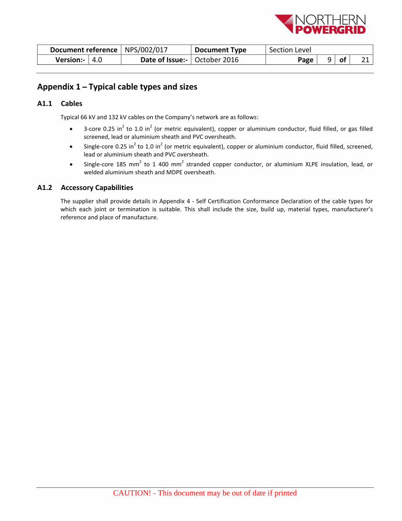
Appendix 1 ̶ Typical cable types and sizes
A1.1 Cables
Typical 66 kV and 132 kV cables on the Company’s network are as follows:
3-core 0.25 in2 to 1.0 in
2 (or metric equivalent), copper or aluminium conductor, fluid filled, or gas filled
screened, lead or aluminium sheath and PVC oversheath.
Single-core 0.25 in2 to 1.0 in
2 (or metric equivalent), copper or aluminium conductor, fluid filled, screened,
lead or aluminium sheath and PVC oversheath.
Single-core 185 mm2 to 1 400 mm
2 stranded copper conductor, or aluminium XLPE insulation, lead, or
welded aluminium sheath and MDPE oversheath.
A1.2 Accessory Capabilities
The supplier shall provide details in Appendix 4 - Self Certification Conformance Declaration of the cable types for which each joint or termination is suitable. This shall include the size, build up, material types, manufacturer’s reference and place of manufacture.

Document reference NPS/002/017 Document Type Section Level
Version:- 4.0 Date of Issue:- October 2016 Page 10 of 21
CAUTION! - This document may be out of date if printed
Appendix 2 ̶ Additional tests for cable terminations
A2.1 Outdoor Terminations
A2.1.1 Salt Fog Test
The method and conditions shall be as specified in BS EN 60507. The salt solution shall have a salinity to be agreed between the Company and supplier. The test voltages shall be 42 kV for 66 kV terminations and 84 kV for 132 kV terminations.
A2.1.2 Heavy Wetting Test
The termination shall be subjected to artificial rain at a rate of 2 mm/min at an angle of 45° to the vertical and with a conductivity of 1 000 µS/cm. The test voltages shall be as specified in A2.1.1. The requirements shall be as specified in BS EN 60507.
A2.1.3 Hydraulic Test
This test applies only to fluid-filled terminations.
The completed insulator component shall be sealed with blanking plates and subjected to internal pressure. The test pressure shall be 12 bar for insulators with maximum static design pressure up to 5.25 bar and 34 bar for insulators with design pressure over 5.25 bar up to 15 bar. The insulator shall withstand the test pressure without leakage for a period not less than 15 minutes.
A2.1.4 Cantilever Load Test
This test applies only to self-supporting terminations.
The method and requirement shall be as specified in BS EN 62155. The termination shall withstand a bending moment not less than the declared available value.
A2.2 GIS Terminations
A2.2.1 Cantilever Load Test
The termination shall be subjected to a bending moment of 4,500 Nm at its base for not less than one minute at ambient temperature. No damage shall be sustained.
A2.2.1 Mechanical Endurance Test
The termination shall be jointed to cable of minimum length 10 m. The termination shall be mounted vertically and subjected to vibration of frequency 100 Hz ± 5% and acceleration not less than 5 g (where g is approximately 10 m/s/s) in all three perpendicular axes. Where each axis is tested individually the test period shall be 30 minutes and where two axes are tested together the test duration shall be 45 minutes.
The rigid insulator component of the termination shall be examined by ultrasonic equipment to detect any damage.

Document reference NPS/002/017 Document Type Section Level
Version:- 4.0 Date of Issue:- October 2016 Page 11 of 21
CAUTION! - This document may be out of date if printed
Appendix 3 ̶ Logistical requirements
A3.1 Storage
To enable the Company to store the product(s) in accordance with the manufacturer’s recommendations, the tenderer should provide details of the recommended storage environment and maximum stacking height with respect to each tendered product.
Details should be provided, where relevant, of the minimum and maximum exposure levels, frequency of exposure and duration of exposure of the packaged item with respect to:
Ambient temperature
Humidity
Water
Dust
Atmospheric corrosion
Impact
Vibration
Solar radiation
A3.2 Packaging and labelling
The tenderer shall ensure that each item is suitably packaged and protected to maintain the product and packaging as “fit for service” prior to installation, taking account of the potential for an outdoor storage environment. All packaging shall be sufficiently durable giving regard to the function, reasonable use and contents of the packaging. Where product packages tendered are made up of sub-packages, all the sub-packages shall, unless varied by this specification, be supplied securely packaged together. Where items are provided in bagged form the material from which the bags are made shall be capable of sustaining the package weight and resisting puncture by the materials within. The tenderer shall submit at the time of tendering the details of the proposed packaging (i.e. materials composition and structure) to be used for each product. Where the tenderer is unable to provide packaging suitable for outdoor storage this should be stated at the time of tender.
In order to maximise storage space all palletised goods shall be supplied in standard returnable box pallets with the following specification. Where applicable, suppliers shall also indicate the maximum number of units of each product that are storable per box pallet.
Size – 1 200 mm (w) x 1 000 mm (d) x 750 mm (h)
Weight (empty) – Up to 33 kg
Load capacity – Up to 450 kg
Maximum stacking capacity – 10 high
Suppliers shall also include details of the type of material used to manufacture the box pallets.
The Company will give consideration to innovative alternatives to this packaging specification.
Clearly legible, easily identifiable, durable and unambiguous labelling shall be applied to each individual package and, where relevant, multiple packing of like products. Where product packages tendered are made up of sub-packages each sub-packages shall be marked.

Document reference NPS/002/017 Document Type Section Level
Version:- 4.0 Date of Issue:- October 2016 Page 12 of 21
CAUTION! - This document may be out of date if printed
As a minimum requirement the following information shall be included on packaging:
Manufacturer’s trademark or name
Supplier’s trademark or name
Description of item
Date of packaging and/or batch number
Northern Powergrid product code
Weight
Shelf life
Pack quantity
The tenderer shall submit at the time of tendering a sample of the proposed labelling for each product package.

Document reference NPS/002/017 Document Type
Version:- 4.0 Date of Issue:- October 2016 Page 13 of 21
CAUTION! - This document may be out of date if printed
Appendix 4 – Self certification conformance declaration
Power cable accessories for rated voltages 66 kV to 132 kV shall conform to the latest issues of the relevant Standards. The following tables are intended to amplify and/or clarify the requirements of those Standards. This check sheet identifies the relevant clauses of the Standards.
The manufacturer shall declare conformance or otherwise, clause by clause, using the following levels of conformance declaration codes.
Conformance declaration codes
N/A = Clause is not applicable or appropriate to the product
Cs1 = The product conforms fully with the requirements of this clause
Cs2 = The product conforms partially with the requirements of this clause
Cs3 = The product does not conform to the requirements of this clause
Cs4 = The product does not currently conform to the requirements of this clause, but the
manufacturer proposes to modify and test the product in order to conform.
Manufacturer / Supplier:
Manufacturer / Supplier Product Reference:
Northern Powergrid Product Reference (Commodity Code):
Details of the Product Type: (e.g. Voltage, Conductor Type and Size)
Name:
Signature:
Date:
NOTE: One sheet shall be completed for each item or variant submitted.
Instructions for completion
When Cs1 code is entered the supplier shall provide evidence to confirm conformance.
When any other code is entered the reason and supporting evidence for non - conformance shall be entered.
Prefix each remark with the relevant ‘BS EN’ ‘IEC’ or ‘ENA TS’ as appropriate.
Provide technical data sheets and associated drawings for each product.
Document reference NPS/002/017 Document Type
Version:- 4.0 Date of Issue:- October 2016 Page 14 of 21
CAUTION! - This document may be out of date if printed
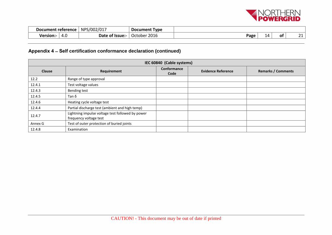
Appendix 4 ̶ Self certification conformance declaration (continued)
IEC 60840 (Cable systems)
Clause Requirement Conformance
Code Evidence Reference Remarks / Comments
12.2 Range of type approval
12.4.1 Test voltage values
12.4.3 Bending test
12.4.5 Tan δ
12.4.6 Heating cycle voltage test
12.4.4 Partial discharge test (ambient and high temp)
12.4.7 Lightning impulse voltage test followed by power frequency voltage test
Annex G Test of outer protection of buried joints
12.4.8 Examination

Document reference NPS/002/017 Document Type
Version:- 4.0 Date of Issue:- October 2016 Page 15 of 21
CAUTION! - This document may be out of date if printed
Appendix 4 ̶ Self certification conformance declaration (continued)
IEC 60840 (Accessories)
Clause Requirement Conformance
Code Evidence Reference Remarks / Comments
12.2 Range of type approval
12.4.1 Test voltage values
12.4.4 Partial discharge test at high temperature
12.4.6 Heating cycle voltage test
12.4.4 Partial discharge test (ambient and high temp.)
12.4.7 Lightning impulse voltage test followed by power frequency voltage test
Annex G Test of outer protection of buried cables
12.4.8 Examination
IEC 60141-1
Clause Requirement Conformance
Code Evidence Reference Remarks / Comments
5.2 Routine pressure test
7.3 Lightning impulse voltage test
7.4 Dielectric security test
Document reference NPS/002/017 Document Type
Version:- 4.0 Date of Issue:- October 2016 Page 16 of 21
CAUTION! - This document may be out of date if printed
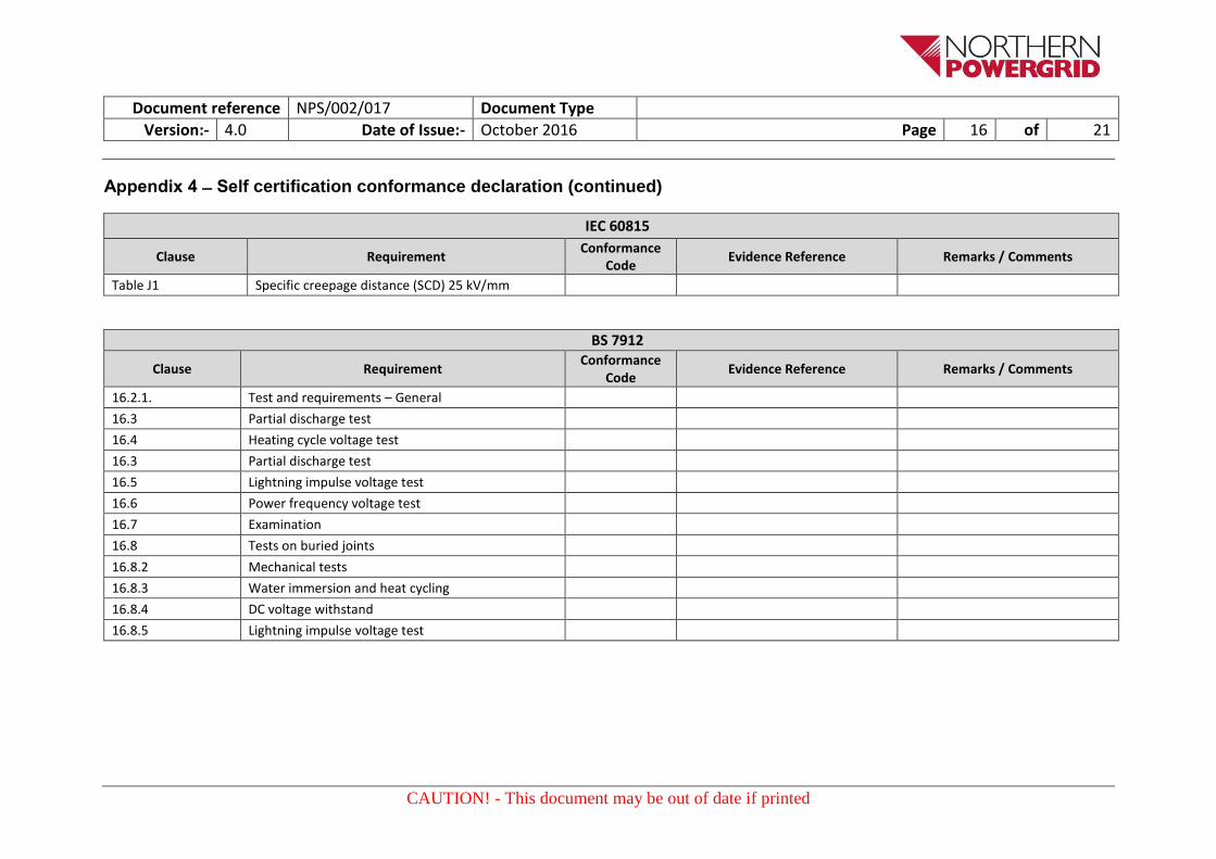
Appendix 4 ̶ Self certification conformance declaration (continued)
IEC 60815
Clause Requirement Conformance
Code Evidence Reference Remarks / Comments
Table J1 Specific creepage distance (SCD) 25 kV/mm
BS 7912
Clause Requirement Conformance
Code Evidence Reference Remarks / Comments
16.2.1. Test and requirements – General
16.3 Partial discharge test
16.4 Heating cycle voltage test
16.3 Partial discharge test
16.5 Lightning impulse voltage test
16.6 Power frequency voltage test
16.7 Examination
16.8 Tests on buried joints
16.8.2 Mechanical tests
16.8.3 Water immersion and heat cycling
16.8.4 DC voltage withstand
16.8.5 Lightning impulse voltage test

Document reference NPS/002/017 Document Type
Version:- 4.0 Date of Issue:- October 2016 Page 17 of 21
CAUTION! - This document may be out of date if printed
Appendix 4 ̶ Self certification conformance declaration (continued)
Additional Tests for Terminations
Clause Requirement Conformance
Code Evidence Reference Remarks / Comments
Tests on outdoor terminations:
A2.1.1 Salt fog test
A2.1.2 Heavy wetting test
A2.1.3 Hydraulic test
A2.1.4 Cantilever load test
Tests for GIS terminations:
A2.2.1 Cantilever load test
A2.2.2 Mechanical endurance test

Document reference NPS/002/017 Document Type
Version:- 4.0 Date of Issue:- October 2016 Page 18 of 21
CAUTION! - This document may be out of date if printed
Appendix 4 ̶ Self certification conformance declaration (continued)
09-04 (66kV and 132kV Impregnated Paper Insulated Oil Filled and Gas Pressure Type Power Cable systems)
Schedule D to be completed by the
manufacturer Requirement
Conformance Code
Evidence Reference Remarks / Comments
Manufacturers Tests reference
9.2 External Insulation
9.2 External Insulation in ER C65 if glass fibre protection box used
9.3 Outdoor sealing Ends in accordance with ENA TS 09-10 if porcelain
11.1 Routine tests
11.1.2 Oil filled accessories Pressure tests
11.1.3 Gas filled accessories Pressure tests
11.2 Sample tests
11.2.2 Test for water tightness

Document reference NPS/002/017 Document Type
Version:- 4.0 Date of Issue:- October 2016 Page 19 of 21
CAUTION! - This document may be out of date if printed
Appendix 5 – Addendum to supplier requirements
A5.1 Work Instructions
Approved work instructions shall be agreed and provided by the supplier.
A5.2 Kitting
All joints and terminations shall be supplied in kit form. All necessary components including connectors, lugs and work instructions shall be supplied in the kit.
A5.3 Tooling
The tooling costs associated with the handling, installation, inspection, maintenance, repair and decommissioning of the product(s) is crucial to the Company’s assessment of the product viability.
To enable the Company to understand and assess the cost of required tooling the tenderer should provide full details of the tooling recommended for use by the manufacturer for the purpose of handling, installation, commissioning, inspection, maintenance, repair and decommissioning of each tendered product. The tenderer should provide, where available, indicative prices applicable to the recommended tooling.
Supplier requirements
Clause Requirement Conformance
Code Remarks
Tooling Are any additional tools required to construct the
joint or termination Y/N

Document reference NPS/002/017 Document Type
Version:- 4.0 Date of Issue:- October 2016 Page 20 of 21
CAUTION! - This document may be out of date if printed
Appendix 6 ̶ Pre-Commission testing, routine inspection and maintenance requirements
Suppliers shall provide details of the recommended pre-commission testing and inspection required.
They shall also provide information regarding periodic inspection and maintenance requirements to be undertaken during the lifetime of their product. Detailed inspection and maintenance instructions shall also be provided.
Testing ,inspection or maintenance
Clause Requirement Conformance
Code Remarks
Pre commissioning Testing
Please state any pre commissioning tests
Y/N
Routine Inspection Please state any inspections required during life time of the joint or termination
Routine Maintenance
Please state any routine maintenance required during the normal expected life of the joint or termination

Document reference NPS/002/017 Document Type
Version:- 4.0 Date of Issue:- October 2016 Page 21 of 21
CAUTION! - This document may be out of date if printed
Appendix 7 ̶ Technical information check list
The following information shall be provided by the supplier for technical review by the Company. Additional information shall be provided if requested.
Requirement Provided
(Y/N)
Full product descriptions and part number/reference
Completed self-certification conformance declaration (Appendix 4)
Complete set of drawings for each variant
Type test evidence
Routine test plan (example)
Pre-commissioning testing and inspection requirements (Appendix 6)
Recommended periodical inspection and maintenance requirements (Appendix 6)
Packaging and delivery information (Appendix 3)


![[XLS]apsebea.orgapsebea.org/files/Tel-APTRANSCO-10.09.2011.xls · Web view132 KV Korutla 080-31,32 132 KV Manthani 0729/029-36 132 KV Huzurabad 033-35 132 KV Mallaram 08723-236164](https://static.fdocuments.net/doc/165x107/5b0e1ab67f8b9aa31f8b92d9/xls-view132-kv-korutla-080-3132-132-kv-manthani-0729029-36-132-kv-huzurabad.jpg)