
NPA 2011-16.pdf
239
TE.RPRO.00034-002© European Aviation Safety Agency. All rights reserved. Proprietary document. Copies are not controlled. Confirm revision status through the EASA-Internet/Intranet. Page 1 of 239 European Aviation Safety Agency NOTICE OF PROPOSED AMENDMENT NPA 2011-16 Qualifications for flying in Instrument Meteorological Conditions RMT.0198 and RMT.0199 (FCL.008(a) and FCL.008(b))
Transcript of NPA 2011-16.pdf

TE.RPRO.00034-002© European Aviation Safety Agency. All rights reserved.
Proprietary document. Copies are not controlled. Confirm revision status through the EASA-Internet/Intranet.
Page 1 of 239
European Aviation Safety Agency
NOTICE OF PROPOSED AMENDMENT
NPA 2011-16
Qualifications for flying in Instrument
Meteorological Conditions
RMT.0198 and RMT.0199 (FCL.008(a) and FCL.008(b))

NPA 2011-16 21 Sep 2011
TE.RPRO.00034-003© European Aviation Safety Agency. All rights reserved. Proprietary document. Copies are not controlled. Confirm revision status through the EASA-Internet/Intranet.
Page 2 of 239
EXECUTIVE SUMMARY
When developing the requirements for the future European regulations for pilot licensing (Part-FCL)
based on the existing JAR-FCL requirements and national regulations, the European Aviation Safety
Agency (‘the Agency’) decided that certain elements had to be postponed and further reviewed.
With its Notice of Proposed Amendment (NPA) 2008-17b the Agency agreed with stakeholder
concerns that the proposed requirements for the Instrument Rating seemed to be too demanding
for Private Pilot Licence (PPL) holders and indicated that a separate rulemaking task would be
started for this purpose. Within the same NPA the need for a review of the existing national
regulations for a cloud flying rating for sailplane pilots was identified and it was decided to include
the development of requirements for a cloud flying rating in the same rulemaking task.
Consequently, the Agency started rulemaking task FCL.008(a) and (b) (new numbers RMT.0198
and RMT.0199), together with experts from National Aviation Authorities (NAAs), flight crew
organisations, training schools and the general aviation community.
This NPA is based on the group’s proposals and contains three main elements:
- an En-route Instrument Rating (EIR) for aeroplane licence holders;
- a more accessible aeroplane Instrument Rating (IR); and
- a cloud flying rating for sailplane pilots
With this NPA the Agency is proposing some key changes in comparison to the provisions of Part-
FCL in order to establish more proportionate rules for PPL holders.
With the proposed Implementing Rules and AMCs for the EIR a new entry level of instrument
training and experience will be introduced. Compared with the existing IR as foreseen in Part-FCL
the EIR requires less training, though nevertheless slightly more detailed flight training than for the
Basic Instrument Flight Module of the IR (according to Part-FCL). As the EIR focuses mainly on the
en-route part of an IFR flight, the future EIR holder should be enabled to fly safely under
Instrument Flight Rules (IFR) and in Instrument Meteorological Conditions (IMC) in the en-route
phase of flight. The rating will not only allow the holder to get used to the en-route IFR procedures
and to cope with unforeseen deteriorating weather conditions, but will also be a module to be
credited for the full IR using the new modular route proposed.
The ‘competency-based’ modular IR will address the need for a more accessible route to obtaining
the full IR for PPL holders as requested by stakeholders. Some key elements of this proposal are a
significantly reduced theoretical knowledge (TK) syllabus focussing only on those items related to
the PPL or Commercial Pilot Licence (CPL) and a different level of TK examinations. Moreover, the
competency-based IR includes a pre-entry course assessment to evaluate prior instrument
experience (e.g. as an EIR holder) as well as the option for flight training with an instrument
instructor outside of an Approved Training Organisation (ATO) before commencing the final training
course at an ATO.
This new rating therefore clearly establishes a more accessible route for general aviation PPL and
CPL holders to obtain an IR. By reducing the costs for obtaining an IR it is expected that more
European pilots will acquire such a rating and thus the skill base will widened thereby creating
positive safety and economic impacts. A high uniform level of safety is ensured by requiring the
applicants to pass exactly the same skill test as established already for the IR in Part-FCL.
The third element, a cloud flying rating for sailplane pilots, already exists in a few Member States.
Based on these national regulations and the group’s proposals, the Agency has developed
Implementing Rules and AMCs and proposes an EU cloud flying rating for sailplane pilots. This
rating would allow them to enter clouds taking into account the airspace structure and the required
minima in different airspace categories and the relevant Air Traffic Control (ATC) procedures.
By introducing a harmonised cloud flying rating, the Agency expects positive economic and safety
impacts across the EASA Member States.
NPA 2011-16 21 Sep 2011
TE.RPRO.00034-003© European Aviation Safety Agency. All rights reserved. Proprietary document. Copies are not controlled. Confirm revision status through the EASA-Internet/Intranet.
Page 3 of 239
TABLE OF CONTENTS
A. EXPLANATORY NOTE ........................................................................................... 4
I. INTRODUCTION .................................................................................................. 4
II. PROCESS AND SCOPE ........................................................................................... 5
III. OVERVIEW OF THE CHANGES PROPOSED IN THIS NPA ..................................................... 6
IV. OPTIONS CONSIDERED AND MAJOR IMPACTS IDENTIFIED ................................................ 13
V. HOW TO COMMENT ON THIS NPA ........................................................................... 15
VI. NEXT STEPS ................................................................................................... 15
B. DRAFT OPINION AND DECISION ....................................................................... 16
I. DRAFT OPINION ............................................................................................... 16
II. DRAFT DECISION ............................................................................................. 23
C. REGULATORY IMPACT ASSESSMENT ............................................................... 197
I. REGULATORY IMPACT ASSESSMENT FOR THE AEROPLANE INSTRUMENT RATINGS .................... 197
II. REGULATORY IMPACT ASSESSMENT FOR THE SAILPLANE CLOUD FLYING RATING .................... 228
NPA 2011-16 21 Sep 2011
TE.RPRO.00034-003© European Aviation Safety Agency. All rights reserved. Proprietary document. Copies are not controlled. Confirm revision status through the EASA-Internet/Intranet.
Page 4 of 239
A. Explanatory Note
I. Introduction
1. With A-NPA 14-2006 the Agency confirmed the need to revise certain areas of the current
private pilot licence (PPL) as defined in the Joint Aviation Requirements (JARs), in order
to address possible deficiencies recognised by the majority of stakeholders. Furthermore,
stakeholders were asked to comment on the proposal to develop an EU Light Aircraft Pilot
Licence with certain privileges and conditions, and especially on the ratings that could be
attached to that licence. A majority of stakeholders mentioned the need for an easily
accessible rating for flying in IMC and the need for a review and simplification of the
existing JAR-FCL IR.
2. During the transfer of JAR-FCL requirements into the proposal for EASA Implementing
Rules, the FCL.001 group and the MDM.032 group (dealing with better regulations for
general aviation) realised that the existing requirements for the IR were too demanding
for a PPL holder. Some of the groups’ experts were in favour of developing a rating
similar to the national IMC rating introduced in the United Kingdom (UK), which allows
the holder of such a rating to fly only in IMC in certain classes of UK airspace. However,
the groups could not agree on an additional rating to fly in IMC with lower training
requirements than the current requirements for the IR. Due to the time constraints for
developing the Implementing Rules for pilot licensing, it was agreed to start a separate
rulemaking task for this issue.
3. In parallel to the transfer of the JAR-FCL requirements into the new rules, additional
requirements for pilot licences, ratings and certificates for aircraft categories other than
aeroplanes and helicopters had to be developed in order to be included in Part-FCL. The
Agency reviewed the existing national requirements for different ratings and discussed
with the FCL.001 rulemaking group the need for further ratings in addition to the IR and
the night qualification as established already in Part-FCL and JAR-FCL. Member States
were contacted in order to evaluate the current situation and to identify which ratings
should be harmonised at the EU level. Based on the input received, the Agency decided
to develop additional ratings for aerobatics, towing, night flying, mountain flying and for
test flights. The creation of a cloud flying rating for sailplane pilots was discussed with
the experts and it was finally decided not to develop such requirements at that stage.
However, the Agency indicated already in NPA 2008-17b that the development of
requirements for a sailplane cloud flying rating would be included in a separate
rulemaking task dealing with qualifications for pilots to fly in IMC or under IFR.
4. Rulemaking task FCL.008 was created in 2009 and a group with experts from NAAs, flight
crew organisations, training schools as well as from the general aviation community was
established. The main objectives of the group, as explained in the Terms of Reference
(ToR)1 for this task, were to:
- Review the existing JAR-FCL requirements for the IR to evaluate the possibility of
reducing these requirements for private pilots flying under IFR. This evaluation
should take into account the Standards and Recommended Practices (SARPs) for the
issue of an IR contained in Annex 1 published by the International Civil Aviation
Authority (ICAO).
- Review the requirements of the UK IMC rating and other national qualifications for
flying in IMC and consider whether there is a need to develop an additional EU
rating to fly in IMC with reduced training but also with limited privileges.
1 The Terms of Reference (ToR) FCL.008 (a) & (b) as published on the Agency’s website
http://www.easa.europa.eu/rulemaking/terms-of-reference-and-group-composition.php#FCL.

NPA 2011-16 21 Sep 2011
TE.RPRO.00034-003© European Aviation Safety Agency. All rights reserved. Proprietary document. Copies are not controlled. Confirm revision status through the EASA-Internet/Intranet.
Page 5 of 239
- Review the existing national requirements for cloud flying with sailplanes and assess
the need for an additional EU rating for sailplane pilots to fly in IMC.
- Take into account ATC requirements regarding IFR flights.
- Amend the proposed requirements (Part-FCL based on JAR-FCL) for the IR if
necessary.
5. The rulemaking group experts followed these objectives closely. They reviewed the
existing requirements for national and third country ratings to fly in IMC and developed
not only a more accessible IR for private pilots but also proposed an en-route instrument
rating and a sailplane cloud flying rating. The group fulfilled all the given tasks and made
useful as well as progressive contributions in the proposals they delivered. The Agency
reviewed these draft proposals and decided to include all three training routes / ratings in
this NPA. Some elements were replaced or amended by the Agency taking into account
the structure and general principles of Part-FCL and the basic principles of Regulation
(EC) No 216/2008.
6. During the drafting phase the Agency and the group members took special consideration
of the requirements in place for the IR issued by the Federal Aviation Administration
(FAA) in the United States of America and the UK IMC rating issued by the Civil Aviation
Authority (CAA) in the UK. It was concluded that the UK IMC rating, because of the
specific needs when operating in the European common airspace and the level of training
delivered compared to the privileges given, could not be transferred into the future EU
system.
7. Although the conversion of existing IMC ratings is not within the scope of this task, the
Agency is aware that this issue is closely linked to it. This NPA provides several options
for pilots with prior instrument experience to be credited towards the new ratings.
However, it should be mentioned at this stage that a conversion of existing IMC ratings is
already covered by the draft Commission Regulation laying down technical requirements
and administrative procedures related to civil aviation aircrew pursuant to Regulation
(EC) No 216/2008 of the European Parliament and of the Council. This draft Regulation
clearly defines that Member States should convert existing licences and ratings into Part-
FCL licences and ratings. It is highlighted in this Regulation that Member States should
aim at allowing pilots to, as far as possible, maintain their current scope of activities and
privileges. The Agency already discussed this issue with the CAA UK and industry experts
in order to identify possible options for UK IMC holders. The most favourable solution
seems to be that a Part-FCL licence and an IR will be issued with certain conditions on
the basis of a specific conversion report in order to reflect the current privileges held.
This would allow the existing UK IMC holders to continue to exercise their IMC privileges.
II. Process and scope
1. The European Aviation Safety Agency2 developed this NPA in line with the rulemaking
Procedure3.
2 The Agency is directly involved in the rule-shaping process. It assists the Commission in its
executive tasks by preparing draft regulations for the implementation of the Basic Regulation and amendments thereof, which are adopted as ‘Opinions’ (Article 19(1)). It also adopts Certification Specifications, Acceptable Means of Compliance and Guidance Material to be used in the certification process and to facilitate the implementation of the Basic Regulation and its implementing rules (Articles 18(c) and 19(2)).
3 The Agency is bound to follow a structured rulemaking process as required by Article 52(1) of the
Basic Regulation. Such a process has been adopted by the Agency’s Management Board and is
referred to as the ‘Rulemaking Procedure’. See Management Board Decision concerning the procedure to be applied by the Agency for the issuing of Opinions, Certification Specifications and Guidance Material (Rulemaking Procedure), EASA MB 08 2007, 13.6.2007.
NPA 2011-16 21 Sep 2011
TE.RPRO.00034-003© European Aviation Safety Agency. All rights reserved. Proprietary document. Copies are not controlled. Confirm revision status through the EASA-Internet/Intranet.
Page 6 of 239
2. This rulemaking activity is included in the Agency’s Rulemaking Programme for 2011-
2014 in line with the Rulemaking Procedure. It implements the rulemaking task FCL.008
‘Qualifications for flying in Instrument Meteorological Conditions (IMC)’.
3. The scope of this rulemaking activity is defined in the Terms of Reference (ToR) FCL.008
(a) & (b).
4. The text of this NPA has been developed by the Agency based on the input of the
FCL.008 rulemaking group. It is submitted for consultation of all interested parties in
accordance with Article 52 of the Regulation (EC) No 216/20084 (‘the Basic Regulation’)
and Articles 5(3) and 6 of the Rulemaking Procedure.
III. Overview of the changes proposed in this NPA
1. En-route Instrument Rating (EIR)
1.1. General
As discussed above, this NPA addresses three major issues. The first one is the creation
of an en-route instrument rating. This additional rating shall be an extension of the
training and the privileges of the PPL or the CPL. Although the initial starting point for this
task was to develop a more accessible instrument rating for PPL holders, the Agency
agrees with the proposal of the rulemaking group not to limit the new ratings to PPL only.
As the Agency expects that these ratings will also lead to an increase of VFR rated CPL
holders taking up the training for one of the two new instrument ratings, it is proposed to
widen the scope and to allow CPL holders to also receive training for these ratings.
The EIR will provide the privilege to conduct flights under IFR and in IMC in the en-route
phase of flight for all the aeroplane types or classes for which a type or class rating is
held. The holder of such a rating must not only take off in VMC but must also ensure that
the approach and landing will be done under Visual Flight Rules (VFR). The proposed
AMC1 FCL.825 provides further details on how to comply with these requirements. The
training will focus on the skills to fly an aeroplane under IFR and in IMC in the en-route
phase, but will also include some emergency approaches and landing exercises as well as
flights in controlled airspace under IFR with a high density of traffic. It is proposed with
this NPA to create a new additional requirement FCL.825 in Subpart I of Part-FCL
containing the provisions for this new rating.
1.2. Flight instruction
The training course shall consist of at least 15 hours of flight time by reference to
instruments. At least 10 hours of the required instrument flight instruction time shall be
completed in an ATO whereas the remaining flight time may be completed under the
supervision of an Instrument Rating Instructor (IRI(A)) or a Flight Instructor (FI(A))
holding the privileges to provide training for the EIR or IR. AMC 2 FCL.825 details the
required flight training exercises. This training syllabus for the EIR comprises the basic
instrument flight exercises, the en-route IFR procedures, the transition from IFR to VFR
before reaching the Minimum Sector Altitude (MSA) and includes also flights in controlled
airspace under IFR with a high density of traffic and at least one emergency IFR
approach.
4 Regulation (EC) No 216/2008 of the European Parliament and the Council of 20 February 2008 on
common rules in the field of civil aviation and establishing a European Aviation Safety Agency, and
repealing Council Directive 91/670/EEC, Regulation (EC) No 1592/2002 and Directive 2004/36/EC (OJ L 79, 19.3.2008, p. 1), as last amended by Regulation (EC) No 1108/2009 (OJ L 309, 24.11.2009, p. 51).
NPA 2011-16 21 Sep 2011
TE.RPRO.00034-003© European Aviation Safety Agency. All rights reserved. Proprietary document. Copies are not controlled. Confirm revision status through the EASA-Internet/Intranet.
Page 7 of 239
1.3. Theoretical knowledge instruction and examination
Before taking the theoretical knowledge examination, the applicant for an EIR has to
complete an approved TK course of at least 100 hours of instruction. The main part of
this course may be delivered by computer-based training, e-learning elements or distance
learning but at least 10 hours shall be completed by classroom teaching within an ATO.
Details are proposed in AMC3 FCL.825.
After completion of the TK instruction the applicant for an EIR shall pass a TK
examination which will be the same as the examination proposed for the new
competency-based modular route (see 2.5).
1.4. Skill test
The applicant shall also pass a skill test. The details of this skill test are proposed in
AMC 4 FCL.825. The proposal contains all the en-route exercises of the skill test for the
existing IR, IFR/VFR transitions and some emergency exercises.
1.5. Privileges of instructors and examiners
The NPA also contains a proposal to extend the instructor privileges to provide training
for the EIR. The appropriate requirements in Subpart J will be amended in order to clarify
that the Flight Instructor (FI), the Type Rating Instructor (TRI) and Instrument Rating
Instructor (IRI) who hold the privilege to instruct for the IR will also be allowed to
provide training for the EIR.
The privileges of an Instrument Rating Examiner (IRE) will be extended to conduct skill
tests for the issue and proficiency checks for the revalidation or renewal not only for the
IR but also for the EIR.
1.6. Reasons for proposing this rating
The Agency is proposing this entry level en-route instrument rating as a valuable tool to
reduce the rate of accidents or incidents arising frequently from PPL or CPL holders not
holding an instrument rating who nevertheless inadvertently enter IMC. In these cases,
most private pilots have not been trained on how to handle IMC, resulting in safety
critical situations. The introduction of this rating is expected to reduce the safety risks by
facilitating a wider skill-base to private pilots. Pilots holding an EIR will be able to cope
with these situations. The potential safety risks induced by the fact that training for this
rating mainly focuses on the en-route IFR skills and provides no approach and landing
privileges is mitigated by the restrictions of privileges on the one hand and some specific
training modules for handling emergency situations on the other.
A second important aspect when evaluating the value of this EIR is the fact that the two
new options identified for flying under IFR or in IMC with aeroplanes are closely linked to
each other. The 15 hours of dual instrument flight training for the EIR and in addition the
flight time as pilot-in-command (PIC) exercising the privileges of this rating will be
credited against the instrument flight time needed for the competency-based modular IR.
The Agency therefore believes that the EIR will be also an initial step for many PPL and
CPL holders towards the new competency-based modular IR.
All in all, a clear positive safety impact is expected from this option. Further explanations
can be found in the attached Regulatory Impact Assessment (RIA). Stakeholders are
specifically invited to provide comments on this proposal.
2. Competency-based modular course for the IR(A)
2.1. General
The second option identified and proposed with this NPA is the competency-based
modular IR route. When developing the initial proposals, the rulemaking group discussed
if such a route could also be introduced for helicopters. It was decided not to develop an

NPA 2011-16 21 Sep 2011
TE.RPRO.00034-003© European Aviation Safety Agency. All rights reserved. Proprietary document. Copies are not controlled. Confirm revision status through the EASA-Internet/Intranet.
Page 8 of 239
equivalent route for the IR(H) but to reconsider this issue at a later stage, based on the
experience made with this new course for aeroplane pilots. The Agency agrees with this
proposal and will not introduce a new route for the IR(H) at this stage. However, the
Agency is interested in collecting feedback from the helicopter community on this issue.
2.2. Possible restriction of privileges
The Agency’s proposal for this new competency-based modular course for the IR(A) will
not be restricted to a specific category of aeroplanes. This issue was discussed in detail
with the experts involved in the drafting and several options for possible restrictions of
this rating were proposed. In order to assess this issue, it should be noted that the main
difference between the new route and the existing modular courses is simply the
(competency-based) means of achieving the skills and the different level of theoretical
knowledge required (the proposal in this NPA focuses on the pure IR-related syllabus
items only). The level of skill that has to be proven by the applicant stays the same
although the minimum amount of instrument flight time will be reduced by 10 hours. This
will be ensured by introducing the same skill test contents and using the same category
of instructor and examiner as for the existing IR.
A conclusion was reached in that the deleted syllabus items are only needed for the
operation of high-performance or complex aeroplanes but not for the other aeroplane
classes or types typically flown by a PPL or CPL holder.
There are different options to address this different level of theoretical knowledge. One
solution would be to limit the privileges to certain aeroplane types or classes (e.g. all
aeroplanes except high-performance aeroplanes (HPA) or complex aeroplanes). In order
to extend the privileges later on and to fly other types or classes of aeroplanes under
IFR, the holder should pass an additional IFR examination. A possible way to address this
would be to develop a specific additional IFR theory section for this case and to require
the pilot who wishes to extend the initial privileges of such a restricted IR to take
additional lessons and pass a specific upgrade examination.
A second option would be not to restrict the IR privileges for a PPL or CPL holder who
followed the competency-based modular route but to include the identified additional
theory items in the class and type rating theory as set out in Part-FCL or as mandatory
items (also for the VFR rated pilots) in the HPA course.
The Agency discussed the advantages and disadvantages of these options in detail and
decided to propose with this NPA the second route and not to restrict the privileges of the
IR based on this competency-based modular route. A draft proposal for the additional
theory items to be covered in the theoretical HPA course was developed and is proposed
with the amended AMC1 FCL.720.A containing the HPA syllabus. A separate subsection
(called IFR operation) was created, including all the subjects deleted from the existing IR
syllabus and identified as important theoretical knowledge items to be included for the
operation of high-performance aeroplanes under IFR. The Agency asks stakeholders to
provide specific input on whether they agree with this approach or whether they would
support the limitation of the rating to certain aeroplane categories.
Based on the decision not to limit the privileges, the requirement FCL.605, which
describes the privileges for the IR, was not changed in substance as the new
competency-based course will lead to the same rating.
The reduction of theory items is also the reason for a change proposed by the Agency
related to the crediting of theoretical knowledge towards the IR TK instruction and
examination for an IR in a different aircraft category. The IR holder having completed the
competency-based course will only be credited in full if he/she has also passed the HPA
examination. FCL.035 will be amended to clarify this.

NPA 2011-16 21 Sep 2011
TE.RPRO.00034-003© European Aviation Safety Agency. All rights reserved. Proprietary document. Copies are not controlled. Confirm revision status through the EASA-Internet/Intranet.
Page 9 of 239
2.3. Learning Objectives
One of the main elements of this task was to review the existing JAR-FCL syllabus and
the related Learning Objectives (LOs) for the instrument rating. Based on the group’s
input and further discussions with IR theory experts a significant amount of syllabus
items and LOs was finally deleted from the syllabus. This was done either because these
LOs are covered already by the PPL or CPL syllabus or because they are not relevant for
a PPL or CPL holder operating a non-high performance aeroplane in IMC or under IFR.
The Agency would like to ask stakeholders to study carefully the attached AMCs
containing the tables with the LOs for the seven required subjects and invites them to
provide feedback on the proposed deletions. In order to assist stakeholders in reviewing
these changes and comparing them with the LOs for the existing JAR-FCL IR, the AMC
will also show the table for the JAR-FCL IR LOs. These JAR-FCL tables have not yet been
published by the Agency and will be reviewed and amended by another rulemaking task
(FCL.002). The latest version of these LOs containing a table including the relevant LOs
for the professional licences and the IR is published by the Joint Aviation Authority (JAA)
as FCL Joint Implementation Procedures (JIP) material and is available on the JAA
website5. All the necessary information from the introduction section of each subject was
transferred to a newly created GM1 FCL.615. This GM now contains a short explanation
for the purpose of using these LOs and some further information on the subjects ‘Air Law’
(010) and ‘Flight Planning and Monitoring’ (033).
The Agency would like to highlight that the main issue to be further evaluated is not only
whether the proposed deletions should be kept in this way for the competency-based
modular route but also whether some of these deletions should be taken over also for the
existing IR routes. As already mentioned above, the Agency proposes to include some of
these deleted items (e.g. machmeter, jet streams, simultaneous operation on parallel
instrument runways, Airborne Collision Avoidance System (ACAS), flux valve, high
altitude operation, etc.) in the AMC containing the theoretical knowledge syllabus for the
high-performance aeroplane as they are relevant for the operation of this aeroplane
category. The proposed amendment of AMC1 FCL.725 therefore contains a new IFR
section added to the existing VFR syllabus items. Based on this amendment, the Agency
also proposes to raise the amount of questions foreseen (60 to 100 multiple choice
questions) for the high performance aeroplane TK examination further detailed in
FCL.725. Stakeholders’ feedback on these proposals and on the content of the syllabus
as published in Part-FCL for the HPA course is also expected.
2.4. Flight instruction
The method of attaining an IR(A) following this modular course is competency-based.
However, minimum requirements are stipulated to ensure that the IR following this route
will be an ICAO compliant rating. The training course for the competency-based modular
route is proposed to be added to Appendix 6 as subsection A.2. Taking over the
standards defined in the ICAO SARPs, the Agency proposes that the course shall include
at least 40 hours of flight instruction time by reference to instruments of which a
maximum of 30 hours may be instrument ground training in a Flight and Navigation
Procedures Trainer (FNPT I or II). When the applicant has completed instrument flight
instruction under the supervision of an IRI(A) or an FI(A) holding the privilege to provide
training for the IR or has prior experience of flight time by reference to instruments as
PIC on aeroplanes, under a rating giving the privileges to fly under IFR or in IMC, these
hours may be counted towards the 40 hours above up to a maximum of 30 hours. To
determine the amount of hours credited and the training needs left, the applicant shall
5 The JAA LOs are mentioned in chapter 19 of the FCL JIP (Administrative and Guidance Material,
Section Five: Personnel Licensing, Part Two: Procedures) and are available on the JAA website at
http://www.jaa.nl/licensing/licensing.html (see JAR-FCL Theoretical Knowledge Training & Examinations), titled ‘LO’s 2009 January’ and last modified on 11 January 2010.
NPA 2011-16 21 Sep 2011
TE.RPRO.00034-003© European Aviation Safety Agency. All rights reserved. Proprietary document. Copies are not controlled. Confirm revision status through the EASA-Internet/Intranet.
Page 10 of 239
complete a pre-course assessment flight at an ATO. In any case, the flight instruction
part of the training course shall include at least 10 hours of dual instrument flight
instruction in an aeroplane at an ATO and the total amount of dual instrument instruction
time shall not be less than 25 hours.
The flight training syllabus proposed is detailed in Appendix 6 A.2. All the flying exercises
currently contained in the modular training course for the IR (Basic Instrument Flight
Module and Procedural Instrument Flight Module) are included as well in the syllabus for
the proposed competency-based course.
Stakeholders are asked to give their opinion on whether a specific training route for a
competency-based course towards a multi-engine IR(A) should be developed. So far
Appendix 6 A.2 proposes only an upgrade course of 5 hours in an ATO for the IR(A)
holder who also holds a multi-engine class or type rating and wishes to obtain a multi-
engine IR(A) for the first time.
2.5. Theoretical knowledge instruction and examination
Before taking the theoretical examination the applicant for the competency-based
modular IR has to complete an approved theoretical knowledge (TK) course of at least
100 hours instruction. The course content and the teaching methods are the same as
already explained for the EIR in the section above (see 1.3) and will comply with the
ICAO standards.
After completion of the TK instruction the applicant for the competency-based modular IR
shall pass a TK examination. Based on the changes explained above, the Agency also
reviewed the examination procedures and proposes some important amendments related
to the number and distribution of questions and the time allowed for the examination
with AMC2 ARA.FCL.300. The reduction of questions foreseen (150 questions instead of
the 253 required for the Part-FCL / JAR-FCL IR) is based on the significant reduction of
LOs. The duration of such a theoretical examination is proposed to be 3 hours 50
minutes, which means that the competent authorities might consider combining certain
papers. Depending on the administrative procedures of a certain Member State, this TK
examination may be completed in one day.
2.6. Skill test
The skill test for the competency-based modular route is proposed to be the same as the
IR skill test as detailed in Appendix 7 of Part-FCL and was taken over from JAR-FCL.
2.7. Crediting for third country rating holders
Appendix 6 A.2 also provides a proposal for crediting Part-FCL PPL or CPL holders holding
also a current ICAO-based third country IR(A). With a certain amount of instrument flight
time as PIC, the holder of a Part-FCL licence holding also a third country IR(A) will be
credited in full towards the training course requirements. Nevertheless, the applicant has
to pass the skill test and must demonstrate the appropriate knowledge of Air Law,
Meteorology, Flight Performance and Planning and Human Performance.
The conditions for the acceptance of licences and instrument ratings issued by or on
behalf of third countries (e.g. for pilots not holding a Part-FCL licence) are further
detailed in Annex III of the draft Commission Regulation laying down the requirements
and administrative procedures related to civil aviation aircrew.

NPA 2011-16 21 Sep 2011
TE.RPRO.00034-003© European Aviation Safety Agency. All rights reserved. Proprietary document. Copies are not controlled. Confirm revision status through the EASA-Internet/Intranet.
Page 11 of 239
3. Sailplane cloud flying rating
3.1. General
As an additional issue this NPA addresses also a cloud flying rating for sailplane pilots. It
is proposed to include the provisions for this additional rating in Subpart I as a new
requirement FCL.830.
Holders of a pilot licence with privileges to fly sailplanes shall hold such a rating if they
are to fly in clouds. The main reason for creating such a rating is to extend the operating
range of sailplane pilots under certain weather conditions. The attached RIA provides
further details on why this option was chosen and why such a rating is needed for specific
operations in certain areas of the EU.
This rating already exists in several Member States and the proposals are based on these
existing national regulations. The Agency is aware that this rating is also closely linked to
airspace regulations and ATC procedures. However, as the task FCL.008 focuses only on
licensing requirements, some ATC related issues were taken into consideration but
specific questions like ATC clearances or airspace requirements were not discussed in
detail.
3.2. Flight instruction
The proposed new requirement FCL.830 will be included in Subpart I of Part-FCL
containing additional ratings. In order to start the training for this sailplane cloud flying
rating, the licence holders must have completed at least 30 hours of flight time as PIC on
sailplanes. The training course at an ATO will include theoretical knowledge instruction
and at least 5 hours of dual flight instruction controlling the sailplane solely by reference
to instruments. The exercises to be covered during the training course and the
theoretical knowledge syllabus are proposed with an additional AMC1 FCL.830.
3.3. Skill test
After completion of the training, the applicant has to pass a skill test. An oral
examination of the theoretical knowledge shall be done before initiating the practical skill
test. The content of this skill test (and proficiency check) is further detailed in the
proposed AMC2 FCL.830.
3.4. Validity, revalidation and renewal
The cloud flying rating will be valid for 24 months. For the revalidation or the renewal of
the rating a proficiency check will be required.
3.5. Privileges of instructors and examiners
The NPA contains also a proposal to extend the privileges of a Flight Instructor (FI) for
sailplanes to be allowed to provide training for the cloud flying rating. FCL.905.FI will be
amended in order to clarify that the FI(S) must hold a cloud flying rating and shall
demonstrate the ability to instruct for that rating to an FI specifically qualified for this.
The privileges of a Flight Examiner (FE) will be extended to skill tests and proficiency
checks for the sailplane cloud flying rating, provided that the examiner has completed at
least 200 hours of flight time as a pilot on sailplanes, including at least 10 hours of flight
instruction for the cloud flying rating or other instrument ratings.
4. Changes to be addressed in Part-FCL
The EIR and the sailplane cloud flying rating are new proposals and should be included in
the Implementing Rules for pilot licensing (Part-FCL – Subpart I). Additional AMCs were
developed and shall be included in the relevant sections of AMCs to Part-FCL. The new
competency-based route for the IR(A) shall be addressed in the IR section of Part-FCL
(Subpart G), in an additional subsection of Appendix 6 and in the relevant AMCs.

NPA 2011-16 21 Sep 2011
TE.RPRO.00034-003© European Aviation Safety Agency. All rights reserved. Proprietary document. Copies are not controlled. Confirm revision status through the EASA-Internet/Intranet.
Page 12 of 239
The amended theoretical syllabus is based on the changes proposed for the relevant LOs.
The Agency proposes an additional AMC to FCL.615 and FCL.830 containing the syllabus
items to be covered. The LOs shall be included in seven additional AMCs to FCL.615. As
mentioned above, the existing JAR-FCL LOs for the IR are included in this NPA in order to
facilitate the review and to allow stakeholders’ feedback on the question if the LOs for the
other IR routes should be kept as they are or if they should be amended as well.
In addition to this, certain changes regarding the instructor and examiner privileges are
addressed in Subparts J and K in order to allow the FI(A), TRI(A) and the IRI(A) to
provide training for the EIR and the FI(S) to provide training for the cloud flying rating. It
was also necessary to amend the privileges of certain examiner categories in Subpart K
of Part-FCL in order to allow them to conduct skill tests and proficiency checks for the
EIR and the cloud flying rating. It is also proposed to include the changes of the
examination procedure in the Implementing Rules for the competent authorities (Part-
ARA / ARA.FCL.300).
5. This NPA therefore proposes to amend the following rules:
Draft Commission Regulation laying down technical requirements and administrative
procedures related to civil aviation aircrew pursuant to Regulation (EC) No
216/2008 of the European Parliament and of the Council - Annex I (Part-FCL);
Draft Commission Regulation laying down technical requirements and administrative
procedures related to civil aviation aircrew pursuant to Regulation (EC) No
216/2008 of the European Parliament and of the Council - Annex VI (Part-ARA);
Draft decision of the Executive Director of the European Aviation Safety Agency on
Acceptable Means of Compliance and Guidance Material on the licensing of pilots (as
published in the CRD to NPA 2008-17b);
Draft decision of the Executive Director of the European Aviation Safety Agency on
Acceptable Means of Compliance and Guidance Material related to the Implementing
Rules for authority requirements (as published in the CRD to NPA 2008-22b).
6. The proposed rule changes and amendments have taken into account the development of
European Union and international law (ICAO), and harmonisation with the rules of
authorities of the European Union’s main partners as set out in the objectives of Article 2
of the Basic Regulation.
The proposed new rules for the EIR:
a) take into account the current status of the relevant European Union legislation;
b) are not foreseen in the ICAO SARPs on the Instrument Rating in Annex 1 (Personnel
Licensing); and
c) have no equivalent in the rules of FAA and Transport Canada Civil Aviation (TCCA)
dealing with instrument ratings.
NPA 2011-16 21 Sep 2011
TE.RPRO.00034-003© European Aviation Safety Agency. All rights reserved. Proprietary document. Copies are not controlled. Confirm revision status through the EASA-Internet/Intranet.
Page 13 of 239
The proposed amendments for the competency modular course for the IR:
a) take into account the current status of the relevant European Union legislation and
comply with the aims of the European Parliament6 to develop proportionate
requirements for general aviation;
b) fully comply with the ICAO Standards and Recommended Practices for the
Instrument Rating in ICAO Annex 1 (Personnel Licensing); and
c) have an equivalent in the rules of FAA and TCCA dealing with instrument ratings.
The proposed new rule for the sailplane cloud flying rating:
a) takes into account the current status of the relevant European Union legislation;
b) complies with the ICAO SARPs for the glider pilot licence in Annex 1 (Personnel
Licensing) although a specific cloud flying rating is not mentioned; and
c) has no equivalent in the rules of FAA and TCCA
IV. Options considered and major impacts identified
1. Overview
The Agency developed one Regulatory Impact Assessment (RIA) for aeroplane licence
holders and one for sailplane licence holders. Both RIAs are published in full as separate
annexes (C.I and C.II) to this NPA. This section gives an overview of the options
considered, summarises the most important impacts and thus explains the main reasons
for choosing the preferred option.
2. RIA 1 – Instrument ratings for aeroplane licence holders
Option 0 – No regulatory change (current Part-FCL).
Option 1 (en-route IR) is a new concept where the training requirements are significantly
reduced in comparison to the existing IR and licence holders are not allowed to perform
an approach or a landing in IMC.
Option 2 (accessible competency-based modular IR) reduces not only the amount of
required instrument flight instruction time compared to current Part-FCL (Option 0) but
introduces also a more competency-based approach taking into account prior instrument
time and determining the remaining training needs on the basis of a pre-course
assessment. The ‘accessible IR’ or ‘competency-based IR’ gives full approach and landing
instrument privileges.
Option 3 combines the accessible IR from option 2 with the creation of an en-route IR
from option 1.
Major impacts identified:7
Option 1 (‘En route rating’) is expected to:
Cut the costs of obtaining an instrument rating (IR) by more than half as compared
to Part-FCL, albeit with limited privileges
Increase the number of pilots with an instrument rating by roughly 80 % (from
6400 to 11 500) within an expected 5 year adjustment period
6 European Parliament Resolution ‘An agenda for sustainable future in general and business aviation’
(2008/2134 (INI) 03.02.2009). 7 For the full details of the analysis and underlying assumptions, please refer to Annex C.I. and C.II.

NPA 2011-16 21 Sep 2011
TE.RPRO.00034-003© European Aviation Safety Agency. All rights reserved. Proprietary document. Copies are not controlled. Confirm revision status through the EASA-Internet/Intranet.
Page 14 of 239
Increase the level of safety by allowing pilots to better handle unforeseen weather
conditions
Have an positive effect on the aviation industry by ensuring a pool of potential
future commercial pilots due to the higher number of PPL holders with an
instrument rating
Option 2 (‘Accessible competency based IR’) is expected to:
Cut the costs for obtaining an instrument rating by roughly 20%
Increase the number of pilots with an IR by almost 30% (from 6400 to 8200)
Increase the level of safety by having more pilots trained to handle unforeseen
weather conditions, including approach and landing in IMC. The increase in safety is
considered comparable to option 1. Option 2 implies higher skills for each individual
pilot, but due to the higher costs and lower number of pilots expected to acquire
these skills it is expected to have a comparable impact on the overall level of safety
The higher skill-base among private pilots is also expected to have an positive effect
on the aviation industry by creating a pool of potential future commercial pilots
Option 3 (‘Combined option 1 and 2’) is expected to:
Cut the costs for obtaining an instrument rating in line with options 1 and 2
depending on the rating chosen by the private pilot
Trigger the highest increase in the number of private pilots with between double to
three times more IR ratings depending on the assumptions (between 12 000 and 20
000 in absolute terms).
Create the highest increase to the level of safety by offering two attractive new
routes to instrument ratings with proportionate requirements and privileges for
private pilots
Have the most favourable effect on the skill base of private pilots and create the
largest pool of future commercial pilots
The Agency thus recommends Option 3 as it is expected to have highest overall
benefits in terms of safety, economic as well as social impacts.
3. RIA 2 - Sailplane cloud flying rating
Option 0: current Part FCL, no cloud flying rating foreseen
Option 1 (sailplane cloud flying rating) is an additional rating which will allow the
sailplane pilot licence holder to enter clouds and to fly in IMC if the airspace structure and
national regulations allow to do so.
Option 2 (restricted sailplane cloud flying) is a concept were sailplane pilots will be
allowed to conduct flights in IMC but clear of clouds.
Major impacts identified:8
Option 0 (‘Current Part-FCL’) is expected to:
Prohibit the current practice of cloud flying in eight EASA Member States
As cloud flying increases the operational range of sailplanes, this option would
increase safety risks due to a greater risk for out-landings
Overall this option is expected to have a negative impact on sailplane activity and
thus induce a negative economic impact
Option 1 (‘Full sailplane cloud flying rating’) is expected to:
8 For the full details of the analysis and underlying assumptions, please refer to Annex C.I. and C.II.

NPA 2011-16 21 Sep 2011
TE.RPRO.00034-003© European Aviation Safety Agency. All rights reserved. Proprietary document. Copies are not controlled. Confirm revision status through the EASA-Internet/Intranet.
Page 15 of 239
Have little to no impact on the eight Member States where some form of cloud/IMC
flying is currently practiced
Increase the operational range and thus the level of safety in the 23 Member States
where this is currently not possible
Create an increase in the sailplane activity and thus induce a low positive economic
impact
Option 2 (‘restricted sailplane cloud flying rating’) is expected to:
Have medium negative economic impact on the eight Member States where a full
cloud flying rating currently exists
Increase the operational range and thus the level of safety in the 23 Member States
where this is currently not possible
Potentially not be in line with airspace regulations or Air Traffic Management
procedures in certain Member States
7. The Agency thus recommends Option 1 as it is expected to have highest overall
benefits in terms of safety and economic impacts.
8. As detailed in Annexes C.1 and C.2, the above impact analysis is based on a number of
assumptions and uncertainties. While it is not possible to project the exact absolute
figures, the Agency believes the analysis to be robust when comparing the available
options.
V. How to comment on this NPA
1. Comments to this NPA may be submitted to the Agency within 3 months as of the date of
publication in accordance with Article 6(4) of the Rulemaking Procedure.
2. Comments should be submitted by one of the following methods:
CRT: Submit your comments using the Comment Response Tool (CRT)
available at http://hub.easa.europa.eu/crt/.
E-mail: Comments can be sent by e-mail only in case the use of the CRT is
prevented by technical problems. The(se) problem(s) should be
reported to the CRT webmaster and comments should be sent by
e-mail to [email protected].
Correspondence: If you do not have access to the Internet or e-mail, you can send
your comments by mail to:
Process Support
Rulemaking Directorate
EASA
Postfach 10 12 53
D-50452 Cologne
The deadline for submission of comments is 23 December 2011. Comments received after
this date may not be taken into account.
VI. Next steps
1. Following the closing of the NPA consultation, the Agency will consider all comments and
publish a Comment Response Document (CRD). The CRD will be available on the
Agency’s website and in the Comment Response Tool (CRT).
2. Following the CRD publication, the Agency performs a final review and publishes the
Opinion and/or Decision in due course.
NPA 2011-16 21 Sep 2011
TE.RPRO.00034-003© European Aviation Safety Agency. All rights reserved. Proprietary document. Copies are not controlled. Confirm revision status through the EASA-Internet/Intranet.
Page 16 of 239
B. Draft Opinion and Decision
I. Draft Opinion
The text of the amendment is arranged to show deleted text, new text or new paragraph as
shown below:
1. deleted text is shown with a strike through: deleted
2. new text is highlighted with grey shading: new
3. […] indicates that the remaining text is unchanged in front of or following the reflected
amendment.
Draft Commission Regulation laying down technical requirements and administrative
procedures related to civil aviation aircrew pursuant to Regulation (EC) No 216/2008
of the European Parliament and of the Council – Annex 1 (Part-FCL)
1) Subpart A – General Requirements
Amend FCL.035 as follows:
FCL.035 Crediting of flight time and theoretical knowledge
[…]
(3) The holder of an IR or an applicant having passed the instrument theoretical
knowledge examination for a category of aircraft shall be fully credited towards the
requirements for theoretical knowledge instruction and examination for an IR in
another category of aircraft.
(4) Notwithstanding (b)(3) above, the holder of an IR(A) who has completed a
competency-based modular IR(A) course shall only be credited in full towards the
requirements for theoretical knowledge instruction and examination for an IR
category of aircraft when also having passed the theoretical knowledge instruction
and examination in accordance with FCL.725(b)(4).
[...]
2) Subpart G – Instrument Rating – Section
Amend FCL.600 as follows:
FCL.600 IR - General
Except as provided in FCL.825, Ooperations under IFR on an aeroplane, helicopter, airship or
powered-lift aircraft shall only be conducted by holders of a PPL, CPL, MPL and ATPL with an IR
appropriate to the category of aircraft or when undergoing skill testing or dual instruction.
[…]
3) Subpart H – Class and type ratings – Section 1
Amend FCL.725 as follows:

NPA 2011-16 21 Sep 2011
TE.RPRO.00034-003© European Aviation Safety Agency. All rights reserved. Proprietary document. Copies are not controlled. Confirm revision status through the EASA-Internet/Intranet.
Page 17 of 239
FCL.725 Requirements for the issue of class and type ratings
[…]
(b) Theoretical knowledge examination. The applicant for a class or type rating shall pass
a theoretical knowledge examination organised by the ATO to demonstrate the level of
theoretical knowledge required for the safe operation of the applicable aircraft class or
type.
[…]
(4) For single-pilot aeroplanes that are classified as high performance aeroplanes,
the examination shall be written and comprise at least 6100 multiple-choice
questions distributed appropriately across the main subjects of the syllabus.
[…]
4) Subpart H – Class and type ratings – Section 2
Amend FCL.740 as follows:
FCL.740.A Revalidation of class and type ratings - aeroplanes
(a) Revalidation of multi-engine class ratings and type ratings. For revalidation of multi-
engine class ratings and type ratings, the applicant shall:
[…]
(4) The revalidation of an En-route Instrument Rating (EIR) or an IR(A), if held,
may be combined with a proficiency check for the revalidation of a class or type
rating.
[...]
5) Subpart I – Additional Ratings
A new requirement FCL.825 is added:
FCL.825 En-route Instrument Rating (EIR)
(a) Privileges and conditions.
(1) The privileges of the holder of an en-route instrument rating (EIR) are to conduct
flights by day under IFR or in IMC in the en-route phase of flight, with any
aeroplane for which a class or type rating is held.
(2) The holder of the EIR shall only initiate or continue a flight on which he/she intends
to exercise the privileges of his/her rating if the latest available meteorological
information indicates that at the estimated time of arrival at the planned destination
aerodrome the weather conditions will be such as to allow compliance with VFR on
the approach and landing phase of the flight. On departure the holder of this rating
shall not enter IMC below 1000 feet above the highest object within 5 NM.
(3) Pilots who only obtain their first multi-engine class or type rating after the initial
issue of the EIR shall have the privileges of their EIR extended to multi-engine
aeroplanes after completing at least 3 hours of instrument flight instruction in multi-
NPA 2011-16 21 Sep 2011
TE.RPRO.00034-003© European Aviation Safety Agency. All rights reserved. Proprietary document. Copies are not controlled. Confirm revision status through the EASA-Internet/Intranet.
Page 18 of 239
engine aeroplanes in the en-route phase of flight in an ATO and passing the skill
test referred to in (e).
(b) Pre-requisites. Applicants for the EIR shall hold at least a PPL(A) and shall have
completed at least 20 hours of cross-country flight time as PIC in aeroplanes.
(c) Training course. Applicants for an EIR shall have completed, within a period of 24
months:
(1) theoretical knowledge instruction in accordance with FCL.615; and
(2) instrument flight instruction.
(i) The instrument flight instruction for a single-engine EIR shall include at least
15 hours of flight time by reference to instruments. At least 10 hours of the
required instrument flight instruction time shall be completed in an ATO. The
remaining flight time may be completed under the supervision of an IRI(A) or
an FI(A) holding privileges to provide training for the EIR;
(ii) The instrument flight instruction for a multi-engine EIR shall include at least 18
hours of flight time by reference to instruments. At least 13 hours of the
required instrument flight instruction time shall be completed in an ATO. The
remaining flight time may be completed under the supervision of an IRI(A) or
an FI(A) holding privileges to provide training for the EIR.
(d) Theoretical knowledge. Prior to taking the skill test, the applicant shall demonstrate a
level of theoretical knowledge appropriate to the privileges granted, in the subjects
referred to in FCL.615(b).
(e) Skill test. After the completion of the training, the applicant shall pass a skill test in an
aeroplane with an IRE. For a multi-engine EIR, the skill test shall be taken in a multi-
engine aircraft. For a single-engine IR, the test shall be taken in a single-engine aircraft.
(f) Validity, revalidation and renewal.
(1) An EIR shall be valid for 1 year.
(2) Applicants for the revalidation of an EIR shall pass a proficiency check in an
aeroplane within the 3 months immediately preceding the expiry date of the rating.
(3) If an EIR has expired, in order to renew their privileges applicants shall:
(i) complete refresher training provided by an IRI(A) or an FI(A) holding
privileges to provide training for the EIR to reach the level of proficiency
needed; and
(ii) complete a proficiency check.
(4) If the EIR has not been revalidated or renewed within the preceding 7 years, the
applicant shall also be required to pass again the EIR theoretical knowledge
examinations in accordance with FCL.615(b).
6) Subpart I – Additional Ratings
A new requirement FCL.830 is added as follows:
FCL.830 Sailplane Cloud Flying Rating
(a) Holders of a pilot licence with privileges to fly sailplanes shall only operate a sailplane or
a powered sailplane within cloud when they hold a sailplane cloud flying rating.
(b) Applicants for a sailplane cloud flying rating shall have completed at least:
(1) 30 hours as PIC in sailplanes or powered sailplanes after issue of the licence;

NPA 2011-16 21 Sep 2011
TE.RPRO.00034-003© European Aviation Safety Agency. All rights reserved. Proprietary document. Copies are not controlled. Confirm revision status through the EASA-Internet/Intranet.
Page 19 of 239
(2) a training course at an ATO including:
(i) theoretical knowledge instruction; and
(ii) 5 hours of dual flight instruction, controlling the sailplane solely by reference
to instruments;
(3) a skill test with an FE qualified for this purpose.
(c) The sailplane cloud flying rating shall be valid for a period of 24 months. For the
revalidation and renewal, the applicant shall pass a proficiency check.
7) Subpart J – Instructors – Section 2
Amend FCL.905.FI as follows:
FCL.905.FI FI - Privileges and conditions
The privileges of an FI are to conduct flight instruction for the issue, revalidation or renewal of:
[…]
(f) a towing, or aerobatic or in the case of an FI(S), a cloud flying rating, provided that such
privileges are held and the FI has demonstrated the ability to instruct for that rating to an
FI qualified in accordance with (i) below;
(g) an EIR or an IR in the appropriate aircraft category, provided that the FI has:
(1) at least 200 hours of flight time under IFR, of which up to 50 hours may be
instrument ground time in an FFS, an FTD 2/3 or FNPT II;
(2) completed as a student pilot the IRI training course and has passed an assessment
of competence the skill test for the IRI certificate; and
[…]
8) Subpart J – Instructors – Section 4
Amend FCL.905.TRI as follows:
FCL.905.TRI TRI - Privileges and conditions
The privileges of a TRI are to instruct for:
(a) the revalidation and renewal of an EIR or an IRs, provided the TRI holds a valid IR; ….
[...]
9) Subpart J – Instructors – Section 6
Amend FCL.905.IRI as follows:
FCL.905.IRI IRI - Privileges and conditions
(a) The privileges of an IRI are to instruct for the issue, revalidation and renewal of an EIR or
an IR on the appropriate aircraft category.
[…]
NPA 2011-16 21 Sep 2011
TE.RPRO.00034-003© European Aviation Safety Agency. All rights reserved. Proprietary document. Copies are not controlled. Confirm revision status through the EASA-Internet/Intranet.
Page 20 of 239
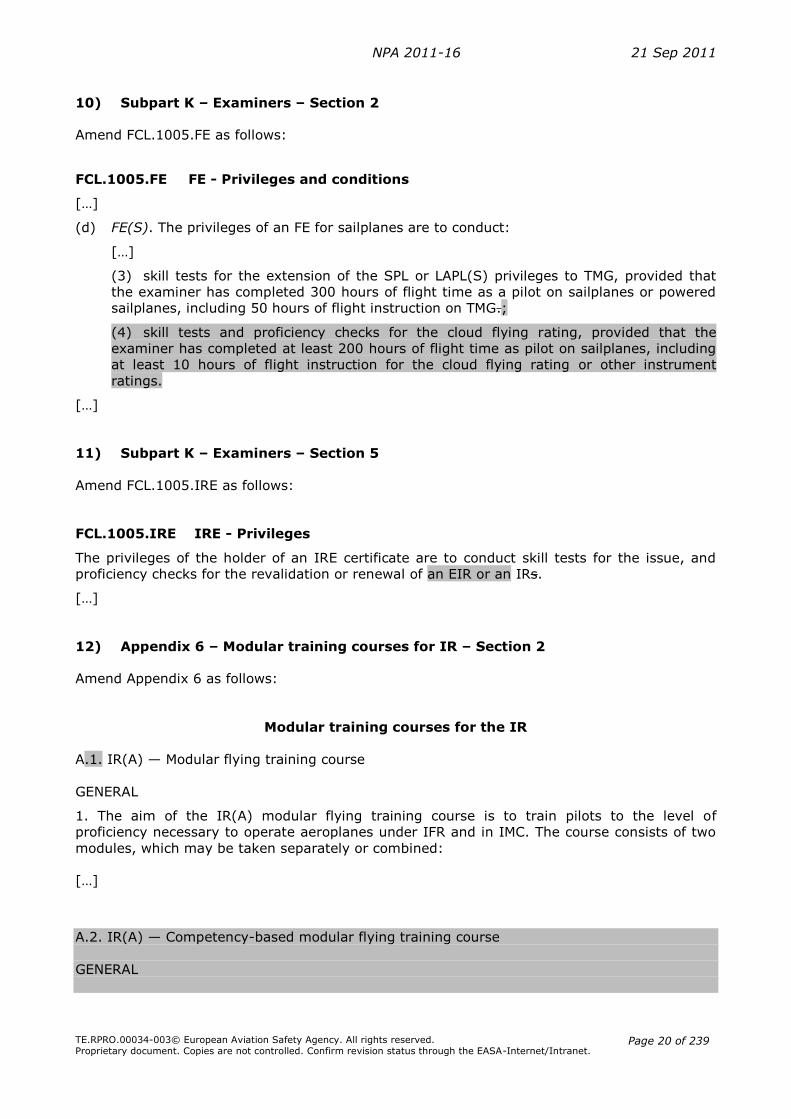
10) Subpart K – Examiners – Section 2
Amend FCL.1005.FE as follows:
FCL.1005.FE FE - Privileges and conditions
[…]
(d) FE(S). The privileges of an FE for sailplanes are to conduct:
[…]
(3) skill tests for the extension of the SPL or LAPL(S) privileges to TMG, provided that
the examiner has completed 300 hours of flight time as a pilot on sailplanes or powered
sailplanes, including 50 hours of flight instruction on TMG.;
(4) skill tests and proficiency checks for the cloud flying rating, provided that the
examiner has completed at least 200 hours of flight time as pilot on sailplanes, including
at least 10 hours of flight instruction for the cloud flying rating or other instrument
ratings.
[…]
11) Subpart K – Examiners – Section 5
Amend FCL.1005.IRE as follows:
FCL.1005.IRE IRE - Privileges
The privileges of the holder of an IRE certificate are to conduct skill tests for the issue, and
proficiency checks for the revalidation or renewal of an EIR or an IRs.
[…]
12) Appendix 6 – Modular training courses for IR – Section 2
Amend Appendix 6 as follows:
Modular training courses for the IR
A.1. IR(A) — Modular flying training course
GENERAL
1. The aim of the IR(A) modular flying training course is to train pilots to the level of
proficiency necessary to operate aeroplanes under IFR and in IMC. The course consists of two
modules, which may be taken separately or combined:
[…]
A.2. IR(A) — Competency-based modular flying training course
GENERAL

NPA 2011-16 21 Sep 2011
TE.RPRO.00034-003© European Aviation Safety Agency. All rights reserved. Proprietary document. Copies are not controlled. Confirm revision status through the EASA-Internet/Intranet.
Page 21 of 239
1. The aim of the competency-based modular flying training course is to train PPL or CPL
holders for the instrument rating taking into account prior instrument flight instruction
and experience. It is designed to provide the level of proficiency needed to operate
aeroplanes under IFR and in IMC. The course shall consist of a combination of instrument
flight instruction under the supervision of an IRI(A) or an FI(A) who holds the privilege to
provide training for the IR and instrument instruction within an ATO.
2. An applicant for such a competency-based modular IR(A) shall be the holder of a PPL(A)
or CPL(A) including the privileges to fly at night.
3. The training shall be completed within 36 months.
4. The course shall comprise:
(a) theoretical knowledge instruction to the IR(A) knowledge level;
(b) instrument flight instruction.
THEORETICAL KNOWLEDGE
5. The applicant shall complete an approved IR(A) theoretical knowledge course of at least
100 hours. The approved IR(A) theoretical knowledge course may contain computer-
based training and e-learning elements. The minimum amount of classroom teaching as
required by ORA.ATO.305 may be combined with the practical flight instruction.
FLIGHT INSTRUCTION
6. The method of attaining an IR(A) following this modular course is competency-based.
However, the minimum requirements below shall be completed by the applicant.
Additional training may be required to reach required competencies.
(a) The flight instruction for the single-engine competency-based modular IR(A) shall
include at least 40 hours of instrument flight instruction by reference to instruments
of which a maximum of 30 hours may be instrument ground training in an FNPT I or
II.
(b) When the applicant has:
- completed instrument flight instruction under the supervision of an IRI(A) or
an FI(A) holding the privilege to provide training for the IR; or
- prior experience of flight time by reference to instruments as PIC on
aeroplanes, under a rating giving the privileges to fly under IFR or in IMC,
these hours may be counted towards the 40 hours above up to a maximum of 30
hours. To determine the amount of hours credited and to establish the training
needs, the applicant shall complete a pre-course assessment flight at an ATO. In
any case, the flight instruction part of the training course shall include at least 10
hours of dual instrument flight instruction in an aeroplane at an ATO and the total
amount of dual instrument instruction time shall not be less than 25 hours.
7. The flight instruction for the competency-based modular IR(A) shall comprise:
(a) procedures and manoeuvres for basic instrument flight covering at least:
- basic instrument flight without external visual cues:
- horizontal flight;
- climbing;
- descent;
- turns in level flight, climbing and descent;

NPA 2011-16 21 Sep 2011
TE.RPRO.00034-003© European Aviation Safety Agency. All rights reserved. Proprietary document. Copies are not controlled. Confirm revision status through the EASA-Internet/Intranet.
Page 22 of 239
- instrument pattern;
- steep turn;
- radio navigation;
- recovery from unusual attitudes;
- limited panel;
- recognition and recovery from incipient and full stall;
(b) pre-flight procedures for IFR flights, including the use of the flight manual and
appropriate air traffic services documents for the preparation of an IFR flight plan;
(c) procedure and manoeuvres for IFR operation under normal, abnormal and
emergency conditions covering at least:
- transition from visual to instrument flight on take-off;
- standard instrument departures and arrivals;
- en-route IFR procedures;
- holding procedures;
- instrument approaches to specified minima;
- missed approach procedures;
- landings from instrument approaches, including circling;
(d) in-flight manoeuvres and particular flight characteristics;
(e) if required, operation of a multi-engine aeroplane in the above exercises, including:
- operation of the aeroplane solely by reference to instruments with one engine
simulated inoperative;
- engine shutdown and restart (to be carried out at a safe altitude unless carried
out in an FFS or FNPT II).
8. Applicants for the competency-based modular IR(A) holding a Part-FCL PPL or CPL and a
valid IR(A) issued in compliance with the requirements of Annex 1 to the Chicago
Convention by a third country may be credited in full towards the training course
mentioned in 4 above. In order to be issued the IR(A), the applicant shall:
(a) successfully complete the skill test for the IR in accordance with Appendix 7;
(b) demonstrate that he/she has acquired knowledge of air law, meteorology, flight
planning and performance, and human performance;
(c) demonstrate that he/she has acquired knowledge of English in accordance with
FCL.055;
(d) have a minimum experience of at least 100 hours of instrument flight time as PIC
on aeroplanes.
PRE COURSE ASSESMENT
9. The content and duration of the pre-course assessment shall be determined by the ATO
based on the prior instrument experience of the applicant.
MULTI-ENGINE
10. The holder of a single-engine IR(A) who also holds a multi-engine class or type rating
wishing to obtain a multi-engine IR(A) for the first time shall complete a course at an
ATO comprising at least 5 hours instrument flight instruction in multi-engine aeroplanes,
of which 3 hours may be in an FFS or FNPT II and shall pass a skill test.
NPA 2011-16 21 Sep 2011
TE.RPRO.00034-003© European Aviation Safety Agency. All rights reserved. Proprietary document. Copies are not controlled. Confirm revision status through the EASA-Internet/Intranet.
Page 23 of 239
II. Draft Decision
The text of the amendment is arranged to show deleted text, new text or new paragraph as
shown below:
1. deleted text is shown with a strike through: deleted
2. new text is highlighted with grey shading: new
3. […] indicates that the remaining text is unchanged in front of or following the reflected
amendment.
Draft Decision of the Executive Director of the European Safety Agency amending
draft Decision on Acceptable Means of Compliance and Guidance Material on the
licensing and medical certification of pilots (Part-FCL)
1) Subpart G – Instrument Rating – Section 1
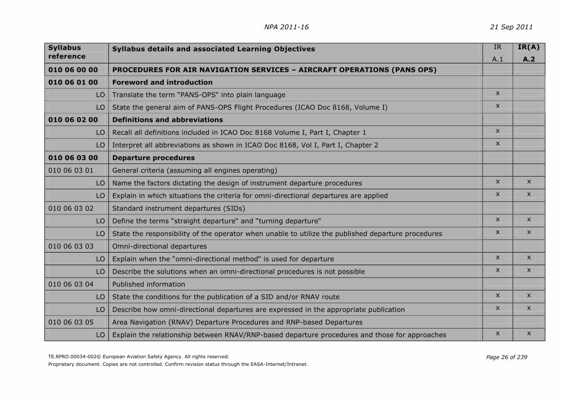
7 new AMCs will be added to FCL.615. They contain the LOs for the TK subjects. The tables
show the LOs for the existing IR (IR - A.1) in the left column and in the right column the
proposed LOs to be taken into account for the EIR TK instruction and for the competency-
based route (IR(A) - A.2).
NPA 2011-16 21 Sep 2011
TE.RPRO.00034-002© European Aviation Safety Agency. All rights reserved.
Proprietary document. Copies are not controlled. Confirm revision status through the EASA-Internet/Intranet.
Page 24 of 239
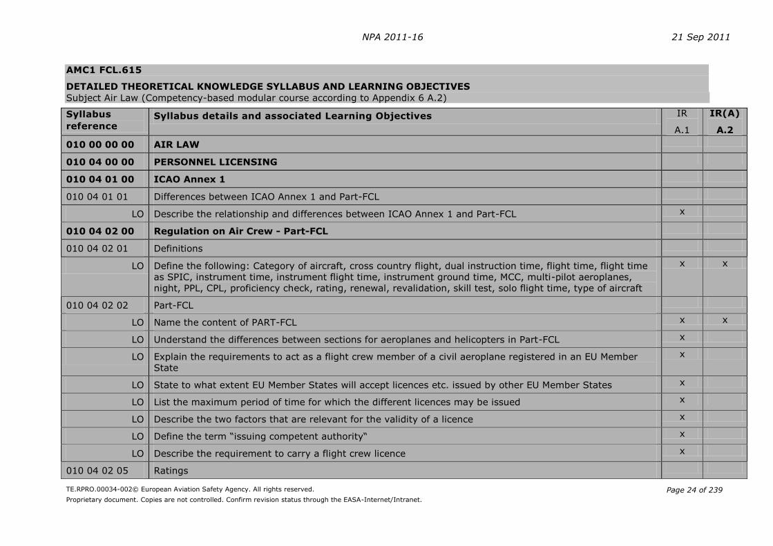
AMC1 FCL.615
DETAILED THEORETICAL KNOWLEDGE SYLLABUS AND LEARNING OBJECTIVES
Subject Air Law (Competency-based modular course according to Appendix 6 A.2)
Syllabus
reference Syllabus details and associated Learning Objectives IR
A.1
IR(A)
A.2
010 00 00 00 AIR LAW
010 04 00 00 PERSONNEL LICENSING
010 04 01 00 ICAO Annex 1
010 04 01 01 Differences between ICAO Annex 1 and Part-FCL
LO Describe the relationship and differences between ICAO Annex 1 and Part-FCL x
010 04 02 00 Regulation on Air Crew - Part-FCL
010 04 02 01 Definitions
LO Define the following: Category of aircraft, cross country flight, dual instruction time, flight time, flight time
as SPIC, instrument time, instrument flight time, instrument ground time, MCC, multi-pilot aeroplanes,
night, PPL, CPL, proficiency check, rating, renewal, revalidation, skill test, solo flight time, type of aircraft
x x
010 04 02 02 Part-FCL
LO Name the content of PART-FCL x x
LO Understand the differences between sections for aeroplanes and helicopters in Part-FCL x
LO Explain the requirements to act as a flight crew member of a civil aeroplane registered in an EU Member
State
x
LO State to what extent EU Member States will accept licences etc. issued by other EU Member States x
LO List the maximum period of time for which the different licences may be issued x
LO Describe the two factors that are relevant for the validity of a licence x
LO Define the term “issuing competent authority“ x
LO Describe the requirement to carry a flight crew licence x
010 04 02 05 Ratings
NPA 2011-16 21 Sep 2011
TE.RPRO.00034-002© European Aviation Safety Agency. All rights reserved.
Proprietary document. Copies are not controlled. Confirm revision status through the EASA-Internet/Intranet.
Page 25 of 239
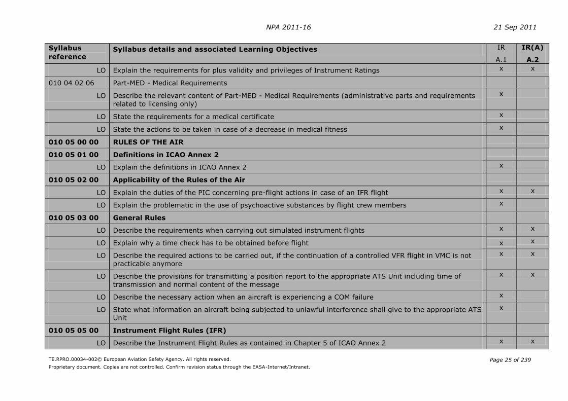
Syllabus
reference Syllabus details and associated Learning Objectives IR
A.1
IR(A)
A.2
LO Explain the requirements for plus validity and privileges of Instrument Ratings x x
010 04 02 06 Part-MED - Medical Requirements
LO Describe the relevant content of Part-MED - Medical Requirements (administrative parts and requirements
related to licensing only)
x
LO State the requirements for a medical certificate x
LO State the actions to be taken in case of a decrease in medical fitness x
010 05 00 00 RULES OF THE AIR
010 05 01 00 Definitions in ICAO Annex 2
LO Explain the definitions in ICAO Annex 2 x
010 05 02 00 Applicability of the Rules of the Air
LO Explain the duties of the PIC concerning pre-flight actions in case of an IFR flight x x
LO Explain the problematic in the use of psychoactive substances by flight crew members x
010 05 03 00 General Rules
LO Describe the requirements when carrying out simulated instrument flights x x
LO Explain why a time check has to be obtained before flight x x
LO Describe the required actions to be carried out, if the continuation of a controlled VFR flight in VMC is not
practicable anymore
x x
LO Describe the provisions for transmitting a position report to the appropriate ATS Unit including time of
transmission and normal content of the message
x x
LO Describe the necessary action when an aircraft is experiencing a COM failure x
LO State what information an aircraft being subjected to unlawful interference shall give to the appropriate ATS
Unit
x
010 05 05 00 Instrument Flight Rules (IFR)
LO Describe the Instrument Flight Rules as contained in Chapter 5 of ICAO Annex 2 x x
NPA 2011-16 21 Sep 2011
TE.RPRO.00034-002© European Aviation Safety Agency. All rights reserved.
Proprietary document. Copies are not controlled. Confirm revision status through the EASA-Internet/Intranet.
Page 26 of 239
Syllabus
reference Syllabus details and associated Learning Objectives IR
A.1
IR(A)
A.2
010 06 00 00 PROCEDURES FOR AIR NAVIGATION SERVICES – AIRCRAFT OPERATIONS (PANS OPS)
010 06 01 00 Foreword and introduction
LO Translate the term “PANS-OPS“ into plain language x
LO State the general aim of PANS-OPS Flight Procedures (ICAO Doc 8168, Volume I) x
010 06 02 00 Definitions and abbreviations
LO Recall all definitions included in ICAO Doc 8168 Volume I, Part I, Chapter 1 x
LO Interpret all abbreviations as shown in ICAO Doc 8168, Vol I, Part I, Chapter 2 x
010 06 03 00 Departure procedures
010 06 03 01 General criteria (assuming all engines operating)
LO Name the factors dictating the design of instrument departure procedures x x
LO Explain in which situations the criteria for omni-directional departures are applied x x
010 06 03 02 Standard instrument departures (SIDs)
LO Define the terms “straight departure“ and “turning departure“ x x
LO State the responsibility of the operator when unable to utilize the published departure procedures x x
010 06 03 03 Omni-directional departures
LO Explain when the “omni-directional method“ is used for departure x x
LO Describe the solutions when an omni-directional procedures is not possible x x
010 06 03 04 Published information
LO State the conditions for the publication of a SID and/or RNAV route x x
LO Describe how omni-directional departures are expressed in the appropriate publication x x
010 06 03 05 Area Navigation (RNAV) Departure Procedures and RNP-based Departures
LO Explain the relationship between RNAV/RNP-based departure procedures and those for approaches x x

NPA 2011-16 21 Sep 2011
TE.RPRO.00034-002© European Aviation Safety Agency. All rights reserved.
Proprietary document. Copies are not controlled. Confirm revision status through the EASA-Internet/Intranet.
Page 27 of 239
Syllabus
reference Syllabus details and associated Learning Objectives IR
A.1
IR(A)
A.2
010 06 04 00 Approach procedures
010 06 04 01 General criteria
LO General criteria (except table “Speeds for procedure calculations") of Approach Procedure Design.
Instrument Approach Areas, Accuracy of fixes, Fixes formed by Intersections intersection fix tolerance
factors, other fix tolerance factors, Approach Area Splays, Descent Gradient)
x
LO Name the five possible segments of an instrument approach procedure x x
LO Give reasons for establishing aircraft categories for the approach x x
LO State the maximum angle between the final approach track and the extended RWY centre-line to still
consider a non-precision-approach as being a “Straight-In Approach“
x x
LO State the minimum obstacle clearance provided by the minimum sector altitudes (MSA) established for an
aerodrome
x x
LO Describe the point of origin, shape, size and sub-divisions of the area used for MSAs x x
LO State that a pilot shall apply wind corrections wind when carrying out an instrument approach procedures x x
LO Name the most significant performance factor influencing the conduct of Instrument Approach Procedures x x
LO Explain why a Pilot should not descend below OCA / Hs which are established for -precision approach
procedures -a non-precision approach procedures - visual (circling) procedures
x x
LO Describe in general terms, the relevant factors for the calculation of operational minima x x
LO Translate the following abbreviations into plain language: DA, DH, OCA, OCH, MDA, MDH, MOC, DA/H,
OCA/H, MDA/H
x x
LO Explain the relationship between the terms: DA, DH, OCA, OCH, MDA, MDH, MOC, DA/H, OCA/H, MDA/H x x
010 06 04 02 Approach Procedure Design
LO Describe how the vertical cross-section for each of the five approach segments is broken down into the
various areas
x x
LO State within which area of the cross-section the Minimum Obstacle Clearance (MOC) is provided for the
whole width of the area
x x

NPA 2011-16 21 Sep 2011
TE.RPRO.00034-002© European Aviation Safety Agency. All rights reserved.
Proprietary document. Copies are not controlled. Confirm revision status through the EASA-Internet/Intranet.
Page 28 of 239
Syllabus
reference Syllabus details and associated Learning Objectives IR
A.1
IR(A)
A.2
LO Define the terms IAF, IF, FAF, MAPt and TP x x
LO Name the area within which the plotted point of an intersection fix may lie x
LO Explain by which factors the dimensions of an intersection fix are determined x
LO State the accuracy of facilities providing track (VOR, ILS, NDB) x x
LO Describe the “other fix tolerance factors“: Surveillance Radar (Terminal Area Radar / TAR, En-route
surveillance radar / RSR), DME, 75 MHz Marker Beacon, Fixes overhead a station (VOR, NDB)
x
LO Describe the basic information relating to approach area splays x x
LO State the optimum descent gradient (preferred for a precision approach) in degrees and percent x x
010 06 04 03 Arrival and approach segments
LO Name the five standard segments of an instrument APP procedure and state the beginning and end for each
of them
x x
LO Describe where an ARR route normally ends x x
LO State whether or not omni-directional or sector arrivals can be provided x x
LO Explain the main task for the initial APP segment x x
LO Describe the maximum angle of interception between the initial APP segment and the intermediate APP
segment (provided at the intermediate fix) for a precision APP and a non-precision APP
x x
LO Describe the main task of the intermediate APP segment x x
LO State the main task of the final APP segment x x
LO Name the two possible aims of a final APP x x
LO Explain the term “final approach point“ in case of an ILS approach x x
LO State what happens if an ILS GP becomes inoperative during the APP x x
010 06 04 04 Missed Approach
LO Name the three phases of a missed approach procedure and describe their geometric limits x x

NPA 2011-16 21 Sep 2011
TE.RPRO.00034-002© European Aviation Safety Agency. All rights reserved.
Proprietary document. Copies are not controlled. Confirm revision status through the EASA-Internet/Intranet.
Page 29 of 239
Syllabus
reference Syllabus details and associated Learning Objectives IR
A.1
IR(A)
A.2
LO Describe the main task of a missed approach procedure x x
LO State at which height / altitude the missed approach is assured to be initiated x x
LO Define the term “missed approach point (MAPt)“ x x
LO Describe how an MAPt may be established in an approach procedure x x
LO State the pilot‘s reaction if, upon reaching the MAPt, the required visual reference is not established x x
LO Describe what a pilot is expected to do in the event a missed approach is initiated prior to arriving at the
MAPt
x x
LO State whether the pilot is obliged to cross the MAPt at the height / altitude required by the procedure or
whether he is allowed to cross the MAPt at an altitude / height greater than that required by the procedure
x x
010 06 04 05 Visual manoeuvring (circling) in the vicinity of the aerodrome:
LO Describe what is meant by “visual manoeuvring (circling)“ x x
LO Describe how a prominent obstacle in the visual manoeuvring (circling) area outside the final approach and
missed approach area has to be considered for the visual circling
x x
LO State for which category of aircraft the obstacle clearance altitude/height within an established x x
visual manoeuvring (circling) area is determined
LO Describe how an MDA/H is specified for visual manoeuvring (circling) if the OCA /H is known x x
LO State the conditions to be fulfilled before descending below MDA / H in a visual manoeuvring (circling)
approach
x x
LO Describe why there can be no single procedure designed that will cater for conducting a circling approach in
every situation
x x
LO State how the pilot is expected to behave after initial visual contact during a visual manoeuvring (circling) x x
LO Describe what the pilot is expected to do if visual reference is lost while circling to land from an instrument
approach
x x
010 06 04 06 Area navigation (RNAV) approach procedures based on VOR/DME

NPA 2011-16 21 Sep 2011
TE.RPRO.00034-002© European Aviation Safety Agency. All rights reserved.
Proprietary document. Copies are not controlled. Confirm revision status through the EASA-Internet/Intranet.
Page 30 of 239
Syllabus
reference Syllabus details and associated Learning Objectives IR
A.1
IR(A)
A.2
LO Describe the provisions that must be fulfilled before carrying out VOR / DME RNAV approaches x x
LO Explain the disadvantages of the VOR / DME RNAV system x x
LO List the factors on which the navigational accuracy of the VOR / DME RNAV system depends x x
LO State whether the VOR / DME / RNAV approach is a precision or a non-precision procedure x x
010 06 04 07 Use of FMS / RNAV equipment to follow conventional non-precision approach procedures
LO State the provisions for flying the conventional non-precision approach procedures using FMS / RNAV
equipment
x
010 06 05 00 Holding procedures
010 06 05 01 Entry and Holding
LO Explain why deviations from the in-flight procedures of a holding established in accordance with ICAO Doc
8168 are dangerous
x x
LO State that if for any reasons a pilot is unable to conform to the procedures for normal conditions laid down
for any particular holding pattern, he should advise ATC as early as possible.
x x
LO Describe how the right turns holdings can be transferred to left turn holding patterns x x
LO Describe the shape and terminology associated with the holding pattern x x
LO State the bank angle and rate of turn to be used whilst flying in a holding pattern x x
LO Explain why pilots in a holding pattern should attempt to maintain tracks and how this can be achieved x x
LO Describe where outbound timing begins in a holding pattern x x
LO State where the outbound leg in a holding terminates if the outbound leg is based on DME x x
LO Describe the three heading entry sectors for entries into a holding pattern x x
LO Define the terms “parallel entry“, “offset entry“ and “direct entry“ x x
LO Determine the correct entry procedure for a given holding pattern x x
LO State the still air time for flying the outbound entry heading with or without DME x x

NPA 2011-16 21 Sep 2011
TE.RPRO.00034-002© European Aviation Safety Agency. All rights reserved.
Proprietary document. Copies are not controlled. Confirm revision status through the EASA-Internet/Intranet.
Page 31 of 239
Syllabus
reference Syllabus details and associated Learning Objectives IR
A.1
IR(A)
A.2
LO Describe what the pilot is expected to do when clearance is received specifying the time of departure from
the holding point
x x
010 06 05 02 Obstacle clearance (except table)
LO Describe the layout of the basic holding area, entry area and buffer area of a holding pattern x x
LO State which obstacle clearance is provided by a minimum permissible holding level referring to the holding
area, the buffer area (general only) and over high terrain or in mountainous areas
x x
010 06 06 00 Altimeter setting procedures
010 06 06 01 Basic requirements and procedures
LO Describe the two main objectives for altimeter settings x x
LO Define the terms “QNH“ and “QFE“ x x
LO Describe the different terms of altitude or flight levels respectively which are the references during climb or
descent to change the altimeter setting from QNH to 1013.2 hPa and vice versa
x x
LO Define the term “flight level” (FL) x x
LO State where flight level zero shall be located x x
LO State the interval by which consecutive flight levels shall be separated x x
LO Describe how flight levels are numbered x x
LO Define the term “Transition Altitude“ x x
LO State how Transition Altitudes shall normally be specified x x
LO Explain how the height of the Transition Altitude is calculated and expressed in practice x x
LO State where Transition Altitudes shall be published x x
LO Define the term “Transition Level“ x x
LO State when the Transition Level is normally passed to aircraft x x
LO State how the vertical position of aircraft shall be expressed at or below the Transition Altitude and
Transition Level
x x
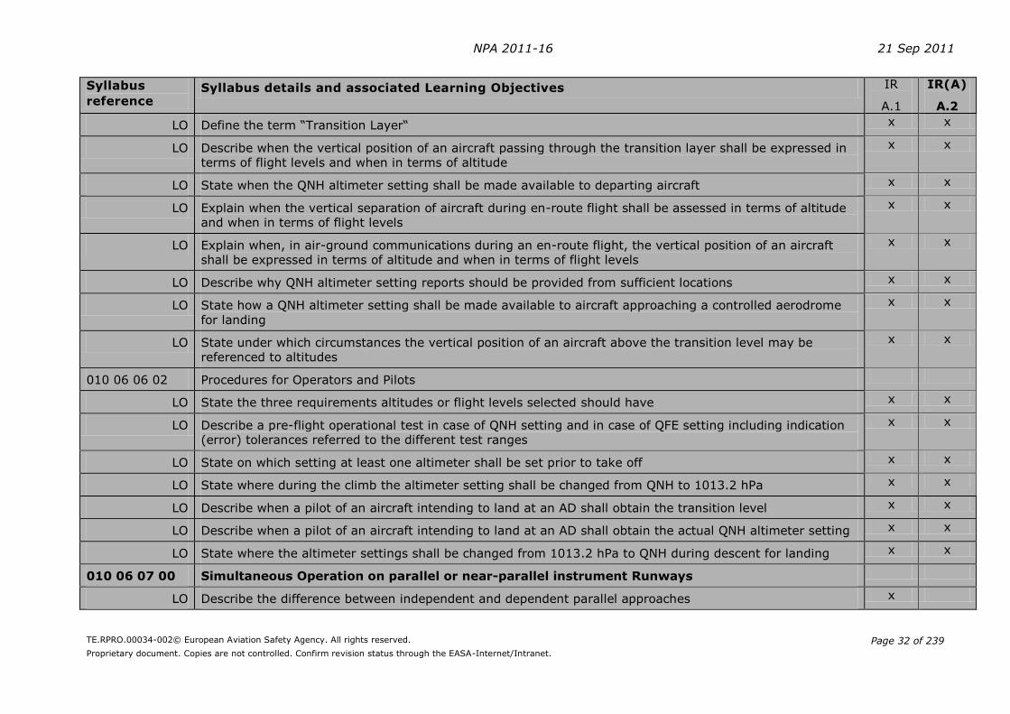
NPA 2011-16 21 Sep 2011
TE.RPRO.00034-002© European Aviation Safety Agency. All rights reserved.
Proprietary document. Copies are not controlled. Confirm revision status through the EASA-Internet/Intranet.
Page 32 of 239
Syllabus
reference Syllabus details and associated Learning Objectives IR
A.1
IR(A)
A.2
LO Define the term “Transition Layer“ x x
LO Describe when the vertical position of an aircraft passing through the transition layer shall be expressed in
terms of flight levels and when in terms of altitude
x x
LO State when the QNH altimeter setting shall be made available to departing aircraft x x
LO Explain when the vertical separation of aircraft during en-route flight shall be assessed in terms of altitude
and when in terms of flight levels
x x
LO Explain when, in air-ground communications during an en-route flight, the vertical position of an aircraft
shall be expressed in terms of altitude and when in terms of flight levels
x x
LO Describe why QNH altimeter setting reports should be provided from sufficient locations x x
LO State how a QNH altimeter setting shall be made available to aircraft approaching a controlled aerodrome
for landing
x x
LO State under which circumstances the vertical position of an aircraft above the transition level may be
referenced to altitudes
x x
010 06 06 02 Procedures for Operators and Pilots
LO State the three requirements altitudes or flight levels selected should have x x
LO Describe a pre-flight operational test in case of QNH setting and in case of QFE setting including indication
(error) tolerances referred to the different test ranges
x x
LO State on which setting at least one altimeter shall be set prior to take off x x
LO State where during the climb the altimeter setting shall be changed from QNH to 1013.2 hPa x x
LO Describe when a pilot of an aircraft intending to land at an AD shall obtain the transition level x x
LO Describe when a pilot of an aircraft intending to land at an AD shall obtain the actual QNH altimeter setting x x
LO State where the altimeter settings shall be changed from 1013.2 hPa to QNH during descent for landing x x
010 06 07 00 Simultaneous Operation on parallel or near-parallel instrument Runways
LO Describe the difference between independent and dependent parallel approaches x
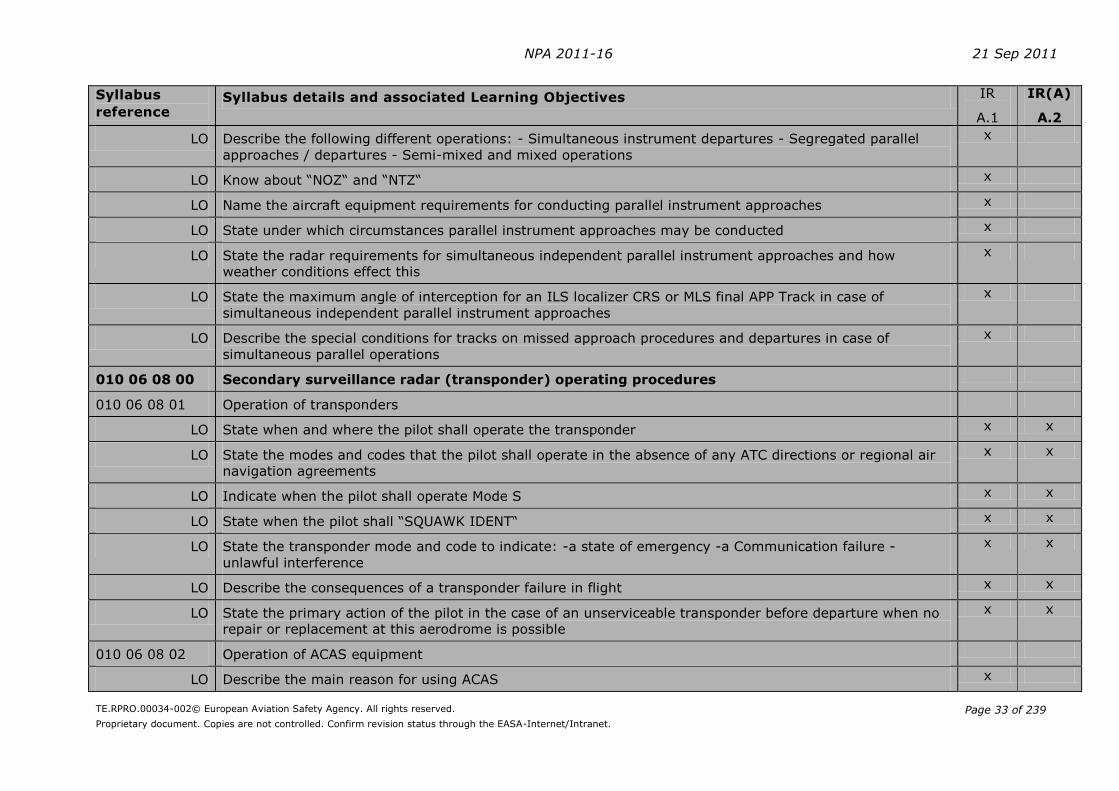
NPA 2011-16 21 Sep 2011
TE.RPRO.00034-002© European Aviation Safety Agency. All rights reserved.
Proprietary document. Copies are not controlled. Confirm revision status through the EASA-Internet/Intranet.
Page 33 of 239
Syllabus
reference Syllabus details and associated Learning Objectives IR
A.1
IR(A)
A.2
LO Describe the following different operations: - Simultaneous instrument departures - Segregated parallel
approaches / departures - Semi-mixed and mixed operations
x
LO Know about “NOZ“ and “NTZ“ x
LO Name the aircraft equipment requirements for conducting parallel instrument approaches x
LO State under which circumstances parallel instrument approaches may be conducted x
LO State the radar requirements for simultaneous independent parallel instrument approaches and how
weather conditions effect this
x
LO State the maximum angle of interception for an ILS localizer CRS or MLS final APP Track in case of
simultaneous independent parallel instrument approaches
x
LO Describe the special conditions for tracks on missed approach procedures and departures in case of
simultaneous parallel operations
x
010 06 08 00 Secondary surveillance radar (transponder) operating procedures
010 06 08 01 Operation of transponders
LO State when and where the pilot shall operate the transponder x x
LO State the modes and codes that the pilot shall operate in the absence of any ATC directions or regional air
navigation agreements
x x
LO Indicate when the pilot shall operate Mode S x x
LO State when the pilot shall “SQUAWK IDENT“ x x
LO State the transponder mode and code to indicate: -a state of emergency -a Communication failure -
unlawful interference
x x
LO Describe the consequences of a transponder failure in flight x x
LO State the primary action of the pilot in the case of an unserviceable transponder before departure when no
repair or replacement at this aerodrome is possible
x x
010 06 08 02 Operation of ACAS equipment
LO Describe the main reason for using ACAS x

NPA 2011-16 21 Sep 2011
TE.RPRO.00034-002© European Aviation Safety Agency. All rights reserved.
Proprietary document. Copies are not controlled. Confirm revision status through the EASA-Internet/Intranet.
Page 34 of 239
Syllabus
reference Syllabus details and associated Learning Objectives IR
A.1
IR(A)
A.2
LO Indicate whether the “use of ACAS indications” described in ICAO Doc 8168 is absolutely mandatory x
LO Explain the pilots reaction required to allow ACAS to fulfil its role of assisting pilots in the avoidance of
potential collisions
x
LO Explain why pilots shall not manoeuvre their aircraft in response to Traffic Advisories only x
LO Explain the significance of Traffic Advisories in view of possible Resolution Advisories x
LO State why a pilot should follow Resolution Advisories immediately x
LO List the reasons which may force a pilot to disregard an Resolution Advisory x
LO Decide how a pilot shall react if there is a conflict between Resolution Advisories in case of an ACAS/ACAS
co-ordinated encounter Resolution Advisories
x
LO Explain the importance of instructing ATC immediately that an Resolution Advisories has been followed x
LO Explain the duties of a pilot as far as ATC is concerned when an Resolution Advisories situation is resolved x
010 07 00 00 AIR TRAFFIC SERVICES AND AIR TRAFFIC MANAGEMENT
010 07 01 00 ICAO Annex 11 - Air Traffic Services
010 07 01 01 Definitions
LO Recall the Definitions given in ICAO Annex 11 x
010 07 01 02 General
LO Name the objectives of Air Traffic Services (ATS) x
LO Describe the three basic types of Air Traffic Services x
LO Describe the three basic types of Air Traffic Control services (ATC) x
LO Indicate when aerodrome control towers shall provide an accurate time check to pilots x
LO State on which frequencies a pilot can expect ATS to contact him in case of an emergency x
LO Understand the procedure for the transfer of an aircraft from one ATC unit to another.
010 07 01 03 Airspace
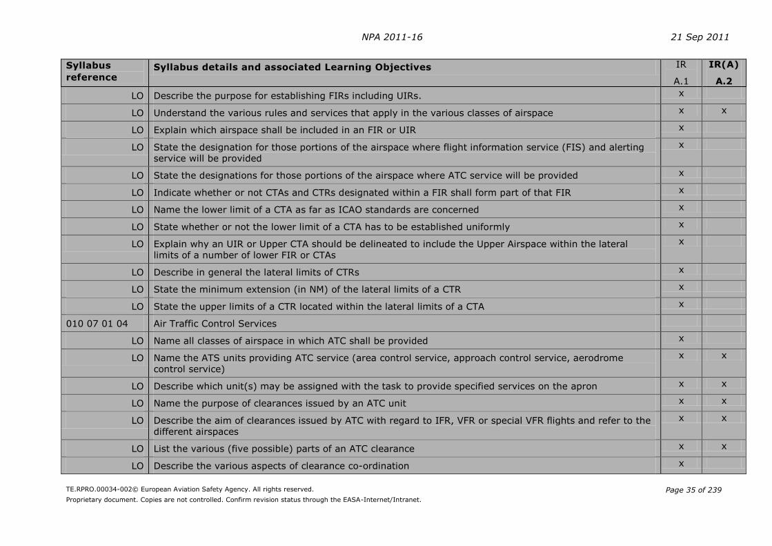
NPA 2011-16 21 Sep 2011
TE.RPRO.00034-002© European Aviation Safety Agency. All rights reserved.
Proprietary document. Copies are not controlled. Confirm revision status through the EASA-Internet/Intranet.
Page 35 of 239
Syllabus
reference Syllabus details and associated Learning Objectives IR
A.1
IR(A)
A.2
LO Describe the purpose for establishing FIRs including UIRs. x
LO Understand the various rules and services that apply in the various classes of airspace x x
LO Explain which airspace shall be included in an FIR or UIR x
LO State the designation for those portions of the airspace where flight information service (FIS) and alerting
service will be provided
x
LO State the designations for those portions of the airspace where ATC service will be provided x
LO Indicate whether or not CTAs and CTRs designated within a FIR shall form part of that FIR x
LO Name the lower limit of a CTA as far as ICAO standards are concerned x
LO State whether or not the lower limit of a CTA has to be established uniformly x
LO Explain why an UIR or Upper CTA should be delineated to include the Upper Airspace within the lateral
limits of a number of lower FIR or CTAs
x
LO Describe in general the lateral limits of CTRs x
LO State the minimum extension (in NM) of the lateral limits of a CTR x
LO State the upper limits of a CTR located within the lateral limits of a CTA x
010 07 01 04 Air Traffic Control Services
LO Name all classes of airspace in which ATC shall be provided x
LO Name the ATS units providing ATC service (area control service, approach control service, aerodrome
control service)
x x
LO Describe which unit(s) may be assigned with the task to provide specified services on the apron x x
LO Name the purpose of clearances issued by an ATC unit x x
LO Describe the aim of clearances issued by ATC with regard to IFR, VFR or special VFR flights and refer to the
different airspaces
x x
LO List the various (five possible) parts of an ATC clearance x x
LO Describe the various aspects of clearance co-ordination x

NPA 2011-16 21 Sep 2011
TE.RPRO.00034-002© European Aviation Safety Agency. All rights reserved.
Proprietary document. Copies are not controlled. Confirm revision status through the EASA-Internet/Intranet.
Page 36 of 239
Syllabus
reference Syllabus details and associated Learning Objectives IR
A.1
IR(A)
A.2
LO State how ATC shall react when it becomes apparent that traffic, additional to that one already accepted,
cannot be accommodated within a given period of time at a particular location or in a particular area, or can
only be accommodated at a given rate
x x
LO Explain why the movement of persons, vehicles and towed aircraft on the manoeuvring area of an AD shall
be controlled by the AD TWR (as necessary)
x
010 07 01 05 Flight Information Service (FIS)
LO State for which aircraft FIS shall be provided x
LO State whether or not FIS shall include the provision of pertinent SIGMET and AIRMET information x
LO State which information FIS shall include in addition to SIGMET and AIRMET information x
LO Indicate which other information the FIS shall include in addition to the special information given in ANNEX
11
x
LO Name the three major types of operational FIS broadcasts x
LO Give the meaning of the acronym ATIS in plain language x
LO Show that you are acquainted with the basic conditions for transmitting an ATIS as indicated in ANNEX 11 x
LO Mention the four possible ATIS messages x
LO List the basic information concerning ATIS broadcasts (e.g. frequencies used, number of ADs included,
updating, identification, acknowledgment of receipt, language and channels, ALT setting)
x
LO State the reasons and circumstances when an ATIS message shall be updated x
010 07 02 00 ICAO Document 4444 - Air Traffic Management
010 07 02 01 Foreword (Scope and purpose)
LO Explain in plain language the meaning of the abbreviation “PANS-ATM” x
LO State whether or not the procedures prescribed in ICAO Doc 4444 are directed exclusively to ATS services
personnel
x
LO Describe the relationship between ICAO Doc 4444 and other documents x
LO State whether or not a clearance issued by ATC units does include prevention of collision with terrain and if x x

NPA 2011-16 21 Sep 2011
TE.RPRO.00034-002© European Aviation Safety Agency. All rights reserved.
Proprietary document. Copies are not controlled. Confirm revision status through the EASA-Internet/Intranet.
Page 37 of 239
Syllabus
reference Syllabus details and associated Learning Objectives IR
A.1
IR(A)
A.2
there is an exception to this, name the exception
010 07 02 02 Definitions
LO
Recall all definitions given in ICAO Doc 4444 except the following: accepting unit / controller, AD taxi
circuit, aeronautical fixed service (AFS), aeronautical fixed station, air-taxiing, allocation, approach funnel,
assignment, data convention, data processing, discrete code, D-value, flight status, ground effect, receiving
unit / controller, sending unit / controller, transfer of control point, transferring unit / controller, unmanned
free balloon
x
010 07 02 03 ATS System Capacity and Air Traffic Flow Management
LO Explain when and where an air traffic flow management (ATFM) service shall be implemented x x
010 07 02 04 General Provisions for Air Traffic services
LO Describe who is responsible for the provision of flight information and alerting service within a flight
information region (FIR) within controlled airspace and at controlled aerodromes
x
010 07 02 05 ATC Clearances
LO Explain “the sole scope and purpose” of an ATC clearance x x
LO State on which information the issue of an ATC clearance is based x x
LO Describe what a PIC should do if an ATC clearance is not suitable x x
LO Indicate who bears the responsibility for maintaining applicable rules and regulations whilst flying under the
control of an ATC unit
x x
LO Name the two primary purposes of clearances issued by ATC units x
LO State why clearances must be issued “early enough” to en-route aircraft x
LO Explain what is meant by the expression “clearance limit” x x
LO Explain the meaning of the phrases ”cleared via flight planned route”, “cleared via (designation) departure”
and “cleared via (designation) arrival “ in an ATC clearance.
x x
LO List which items of an ATC clearance shall always be read back by the flight crew x x
010 07 02 06 Horizontal Speed Control Instructions

NPA 2011-16 21 Sep 2011
TE.RPRO.00034-002© European Aviation Safety Agency. All rights reserved.
Proprietary document. Copies are not controlled. Confirm revision status through the EASA-Internet/Intranet.
Page 38 of 239
Syllabus
reference Syllabus details and associated Learning Objectives IR
A.1
IR(A)
A.2
LO Explain the reason for speed control by ATC x x
LO Define the maximum speed changes that ATC may impose x x
LO State within which distance from the threshold the PIC must not expect any kind of speed control x x
010 07 02 07 Change from IFR to VFR flight
LO Explain how the change from IFR to VFR can be initiated by the PIC x x
LO Indicate the expected reaction of the appropriate ATC unit upon a request to change from IFR to VFR x x
010 07 02 08 Wake turbulence
LO State the wake turbulence categories of aircraft x
LO State the wake turbulence separation minima x
LO Describe how a “Heavy” aircraft shall indicate this on the initial radiotelephony contact with ATS x
010 07 02 09 Altimeter Setting Procedures
LO Define the following terms: - transition level - transition layer - and transition altitude x x
LO Indicate how the vertical position of an aircraft in the vicinity of an aerodrome shall be expressed at or
below the transition altitude, at or above the transition level and while climbing or descending through the
transition layer
x x
LO Describe when the height of an aircraft using QFE during an NDB approach is referred to the landing
threshold instead of the aerodrome elevation
x x
LO Indicate how far altimeter settings provided to aircraft shall be rounded up or down x x
LO Define the expression “lowest usable flight level” x x
LO Determine how the vertical position of an aircraft on a flight en-route is expressed at or above the lowest
usable flight level and below the lowest usable flight level
x x
LO State who establishes the transition level to be used in the vicinity of an aerodrome x x
LO Decide how and when a flight crew shall be informed about the transition level x x
LO State whether or not the pilot can request the transition level to be included in the approach clearance x x

NPA 2011-16 21 Sep 2011
TE.RPRO.00034-002© European Aviation Safety Agency. All rights reserved.
Proprietary document. Copies are not controlled. Confirm revision status through the EASA-Internet/Intranet.
Page 39 of 239
Syllabus
reference Syllabus details and associated Learning Objectives IR
A.1
IR(A)
A.2
LO State in what kind of clearance the QNH altimeter setting shall be included x x
010 07 02 10 Position Reporting
LO Describe when position reports shall be made by an aircraft flying on routes defined by designated
significant points
x x
LO List the six items that are normally included in a voice position report x x
LO Name the requirements for using a simplified position report with Flight level, next position (and time over)
and ensuing significant points omitted
x x
LO Name the item of a position report which must be forwarded to ATC with the initial call after changing to a
new frequency
x x
LO Indicate the item of a position report which may be omitted if SSR Mode C is used x x
LO Explain in which circumstances the indicated air speed should be included in a position report x
LO Explain the meaning of the abbreviation “ADS” x
LO State to which unit an ADS report shall be made x
LO Describe how ADS reports shall be made x
LO Describe which expression shall precede the level figures in a position report if the level is reported in
relation to 1013.2 hPa (standard pressure)
x
010 07 02 11 Reporting of Operational and Meteorological Information
LO List the occasions when special air reports shall be made x
010 07 02 12 Separation methods and minima
LO Explain the general provisions for the separation of controlled traffic x x
LO Name the different kind of separation used in aviation x x
LO Understand the difference between the type of separation provided within the various classes of airspace
and between the various types of flight
x x
LO State who is responsible for the avoidance of collision with other aircraft when operating in VMC x x

NPA 2011-16 21 Sep 2011
TE.RPRO.00034-002© European Aviation Safety Agency. All rights reserved.
Proprietary document. Copies are not controlled. Confirm revision status through the EASA-Internet/Intranet.
Page 40 of 239
Syllabus
reference Syllabus details and associated Learning Objectives IR
A.1
IR(A)
A.2
LO State the ICAO documents in which details of current separation minima are prescribed x x
LO Describe how vertical separation is obtained x x
LO State the required vertical separation minimum x x
LO Describe how the cruising levels of aircraft flying to the same destination and the expected approach
sequence are correlated between each other
x x
LO Name the conditions that must be adhered to, when two aircraft are cleared to maintain a specified vertical
separation between them during climb or descent
x x
LO List the two main methods for horizontal separation x x
LO Describe how lateral separation of aircraft at the same level may be obtained x x
LO Explain the term “Geographical Separation“ x x
LO Describe track separation between aircraft using the same navigation aid or method x x
LO Describe the three basic means for the establishment of longitudinal separation x x
LO Describe the circumstances under which a reduction in separation minima may be allowed x x
LO Indicate the standard horizontal radar separation in NM x x
LO State the wake turbulence radar separation for aircraft in the APP and DEP phases of a flight when an
aircraft is operating directly behind another aircraft at the same ALT or less than 300 m (1000 ft) below
x x
010 07 02 13 Separation in the vicinity of aerodromes
LO Define the expression “Essential Local Traffic” x
LO State which possible decision the PIC may choose if departing aircraft are expedited by suggesting a take-
off direction which is not “into the wind”
x
LO State the condition to enable ATC to initiate a visual approach for an IFR flight x x
LO Indicate whether or not separation will be provided by ATC between an aircraft executing a visual approach
and other arriving or departing aircraft
x x
LO State in which case when the flight crew are not familiar with the instrument approach procedure being
carried out, that only the final approach track has to be forwarded to them by ATC
x x
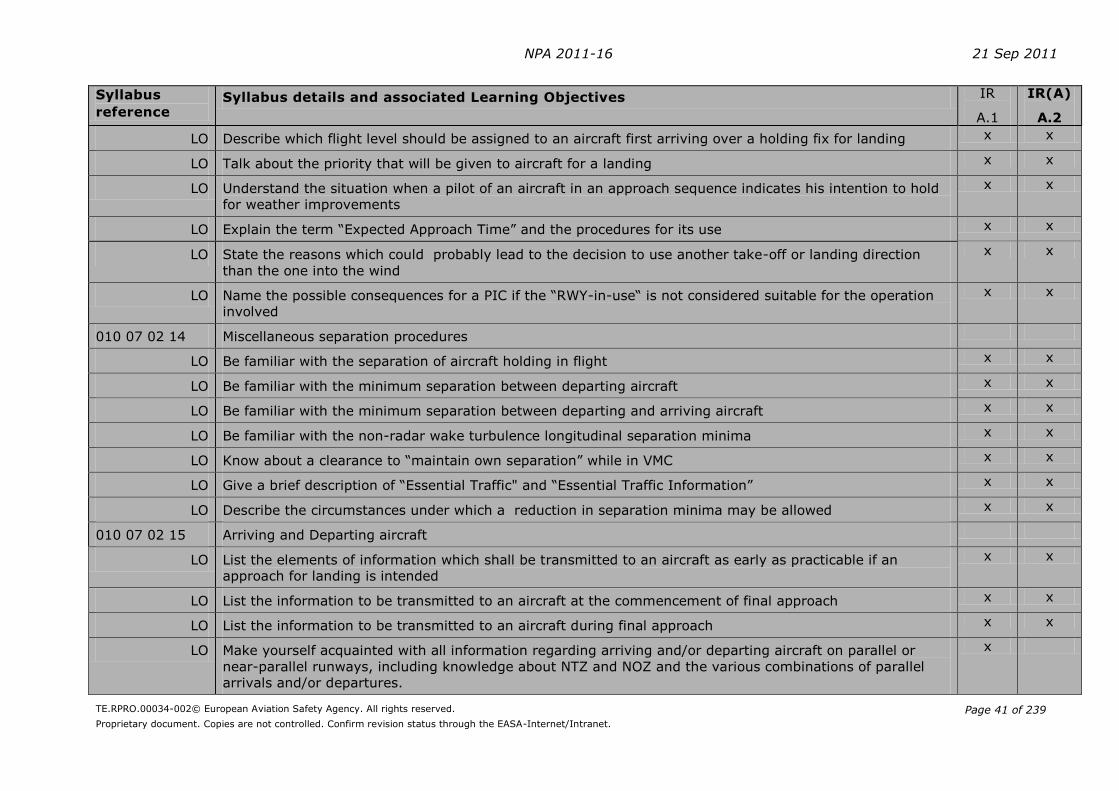
NPA 2011-16 21 Sep 2011
TE.RPRO.00034-002© European Aviation Safety Agency. All rights reserved.
Proprietary document. Copies are not controlled. Confirm revision status through the EASA-Internet/Intranet.
Page 41 of 239
Syllabus
reference Syllabus details and associated Learning Objectives IR
A.1
IR(A)
A.2
LO Describe which flight level should be assigned to an aircraft first arriving over a holding fix for landing x x
LO Talk about the priority that will be given to aircraft for a landing x x
LO Understand the situation when a pilot of an aircraft in an approach sequence indicates his intention to hold
for weather improvements
x x
LO Explain the term “Expected Approach Time” and the procedures for its use x x
LO State the reasons which could probably lead to the decision to use another take-off or landing direction
than the one into the wind
x x
LO Name the possible consequences for a PIC if the “RWY-in-use“ is not considered suitable for the operation
involved
x x
010 07 02 14 Miscellaneous separation procedures
LO Be familiar with the separation of aircraft holding in flight x x
LO Be familiar with the minimum separation between departing aircraft x x
LO Be familiar with the minimum separation between departing and arriving aircraft x x
LO Be familiar with the non-radar wake turbulence longitudinal separation minima x x
LO Know about a clearance to “maintain own separation” while in VMC x x
LO Give a brief description of “Essential Traffic" and “Essential Traffic Information” x x
LO Describe the circumstances under which a reduction in separation minima may be allowed x x
010 07 02 15 Arriving and Departing aircraft
LO List the elements of information which shall be transmitted to an aircraft as early as practicable if an
approach for landing is intended
x x
LO List the information to be transmitted to an aircraft at the commencement of final approach x x
LO List the information to be transmitted to an aircraft during final approach x x
LO Make yourself acquainted with all information regarding arriving and/or departing aircraft on parallel or
near-parallel runways, including knowledge about NTZ and NOZ and the various combinations of parallel
arrivals and/or departures.
x

NPA 2011-16 21 Sep 2011
TE.RPRO.00034-002© European Aviation Safety Agency. All rights reserved.
Proprietary document. Copies are not controlled. Confirm revision status through the EASA-Internet/Intranet.
Page 42 of 239
Syllabus
reference Syllabus details and associated Learning Objectives IR
A.1
IR(A)
A.2
LO State the sequence of priority between aircraft landing (or in the final stage of an approach to land) and
aircraft intending to depart
x x
LO Explain the factors that influence the approach sequence x x
LO State the significant changes in the meteorological conditions in the take-off or climb-out area that shall be
transmitted without delay to a departing aircraft.
x x
LO Describe what information shall be forwarded to a departing aircraft as far as visual or non-visual aids are
concerned
x x
LO State the significant changes that shall be transmitted as early as practicable to an arriving aircraft,
particularly changes in the meteorological conditions.
x x
010 07 02 16 Procedures for Aerodrome Control Service
LO Describe the general tasks of the Aerodrome Control Tower (TWR) when issuing information and clearances
to aircraft under its control
x x
LO List for which aircraft and their given positions or flight situations the TWR shall prevent collisions x x
LO Name the AD equipment the operational failure or irregularity of which shall be immediately reported by the
TWR
x x
LO State that, after a given period of time, the TWR shall report to the ACC or FIC if an aircraft does not land
as expected
x x
LO Describe the procedures to be observed by the TWR whenever VFR operations are suspended x x
LO Explain the term “RWY-in-use“ and its selection x
LO List the information the TWR should give to an aircraft - Prior to taxi for take-off - Prior to take-off - Prior to
entering the traffic circuit
x
LO Explain that a report of surface wind direction given to a pilot by the TWR is magnetic x
LO Explain the exact meaning of the expression “Runway vacated” x
010 07 02 17 Radar services
LO State to what extent the use of radar in air traffic services may be limited x x
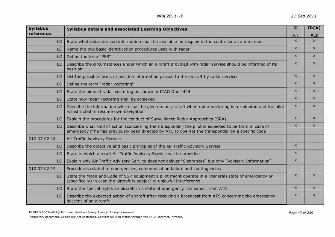
NPA 2011-16 21 Sep 2011
TE.RPRO.00034-002© European Aviation Safety Agency. All rights reserved.
Proprietary document. Copies are not controlled. Confirm revision status through the EASA-Internet/Intranet.
Page 43 of 239
Syllabus
reference Syllabus details and associated Learning Objectives IR
A.1
IR(A)
A.2
LO State what radar derived information shall be available for display to the controller as a minimum x x
LO Name the two basic identification procedures used with radar x x
LO Define the term “PSR“ x x
LO Describe the circumstances under which an aircraft provided with radar service should be informed of its
position
x x
LO List the possible forms of position information passed to the aircraft by radar services x x
LO Define the term “radar vectoring“ x x
LO State the aims of radar vectoring as shown in ICAO Doc 4444 x x
LO State how radar vectoring shall be achieved x x
LO Describe the information which shall be given to an aircraft when radar vectoring is terminated and the pilot
is instructed to resume own navigation
x x
LO Explain the procedures for the conduct of Surveillance Radar Approaches (SRA) x x
LO Describe what kind of action (concerning the transponder) the pilot is expected to perform in case of
emergency if he has previously been directed by ATC to operate the transponder on a specific code
x x
010 07 02 18 Air Traffic Advisory Service
LO Describe the objective and basic principles of the Air Traffic Advisory Service x
LO State to which aircraft Air Traffic Advisory Service will be provided x
LO Explain why Air Traffic Advisory Service does not deliver “Clearances“ but only “Advisory Information“ x
010 07 02 19 Procedures related to emergencies, communication failure and contingencies
LO State the Mode and Code of SSR equipment a pilot might operate in a (general) state of emergency or
(specifically) in case the aircraft is subject to unlawful interference
x x
LO State the special rights an aircraft in a state of emergency can expect from ATC x x
LO Describe the expected action of aircraft after receiving a broadcast from ATS concerning the emergency
descent of an aircraft
x x
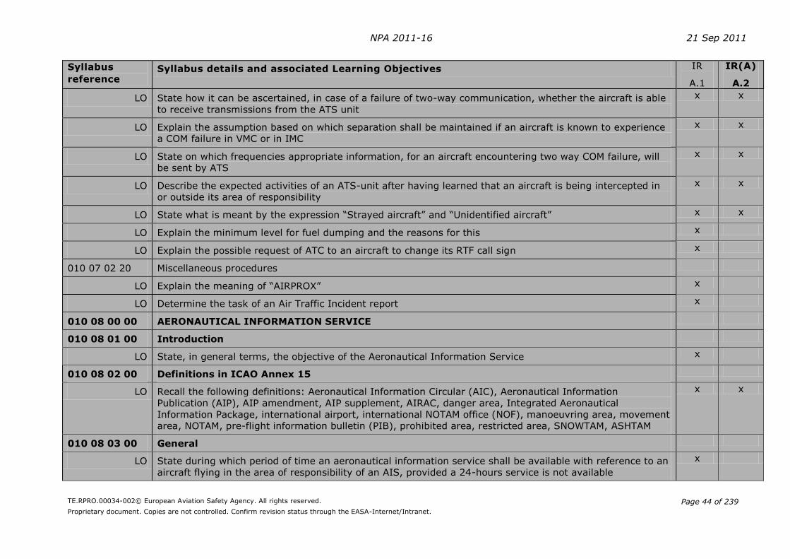
NPA 2011-16 21 Sep 2011
TE.RPRO.00034-002© European Aviation Safety Agency. All rights reserved.
Proprietary document. Copies are not controlled. Confirm revision status through the EASA-Internet/Intranet.
Page 44 of 239
Syllabus
reference Syllabus details and associated Learning Objectives IR
A.1
IR(A)
A.2
LO State how it can be ascertained, in case of a failure of two-way communication, whether the aircraft is able
to receive transmissions from the ATS unit
x x
LO Explain the assumption based on which separation shall be maintained if an aircraft is known to experience
a COM failure in VMC or in IMC
x x
LO State on which frequencies appropriate information, for an aircraft encountering two way COM failure, will
be sent by ATS
x x
LO Describe the expected activities of an ATS-unit after having learned that an aircraft is being intercepted in
or outside its area of responsibility
x x
LO State what is meant by the expression “Strayed aircraft” and “Unidentified aircraft” x x
LO Explain the minimum level for fuel dumping and the reasons for this x
LO Explain the possible request of ATC to an aircraft to change its RTF call sign x
010 07 02 20 Miscellaneous procedures
LO Explain the meaning of “AIRPROX” x
LO Determine the task of an Air Traffic Incident report x
010 08 00 00 AERONAUTICAL INFORMATION SERVICE
010 08 01 00 Introduction
LO State, in general terms, the objective of the Aeronautical Information Service x
010 08 02 00 Definitions in ICAO Annex 15
LO Recall the following definitions: Aeronautical Information Circular (AIC), Aeronautical Information
Publication (AIP), AIP amendment, AIP supplement, AIRAC, danger area, Integrated Aeronautical
Information Package, international airport, international NOTAM office (NOF), manoeuvring area, movement
area, NOTAM, pre-flight information bulletin (PIB), prohibited area, restricted area, SNOWTAM, ASHTAM
x x
010 08 03 00 General
LO State during which period of time an aeronautical information service shall be available with reference to an
aircraft flying in the area of responsibility of an AIS, provided a 24-hours service is not available
x
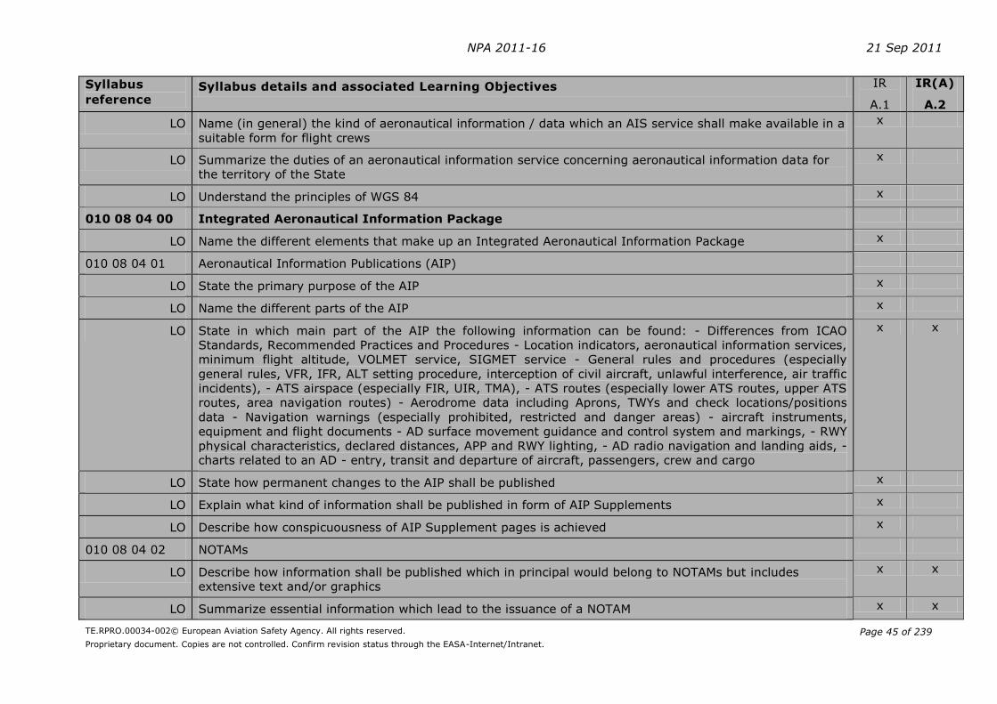
NPA 2011-16 21 Sep 2011
TE.RPRO.00034-002© European Aviation Safety Agency. All rights reserved.
Proprietary document. Copies are not controlled. Confirm revision status through the EASA-Internet/Intranet.
Page 45 of 239
Syllabus
reference Syllabus details and associated Learning Objectives IR
A.1
IR(A)
A.2
LO Name (in general) the kind of aeronautical information / data which an AIS service shall make available in a
suitable form for flight crews
x
LO Summarize the duties of an aeronautical information service concerning aeronautical information data for
the territory of the State
x
LO Understand the principles of WGS 84 x
010 08 04 00 Integrated Aeronautical Information Package
LO Name the different elements that make up an Integrated Aeronautical Information Package x
010 08 04 01 Aeronautical Information Publications (AIP)
LO State the primary purpose of the AIP x
LO Name the different parts of the AIP x
LO State in which main part of the AIP the following information can be found: - Differences from ICAO
Standards, Recommended Practices and Procedures - Location indicators, aeronautical information services,
minimum flight altitude, VOLMET service, SIGMET service - General rules and procedures (especially
general rules, VFR, IFR, ALT setting procedure, interception of civil aircraft, unlawful interference, air traffic
incidents), - ATS airspace (especially FIR, UIR, TMA), - ATS routes (especially lower ATS routes, upper ATS
routes, area navigation routes) - Aerodrome data including Aprons, TWYs and check locations/positions
data - Navigation warnings (especially prohibited, restricted and danger areas) - aircraft instruments,
equipment and flight documents - AD surface movement guidance and control system and markings, - RWY
physical characteristics, declared distances, APP and RWY lighting, - AD radio navigation and landing aids, -
charts related to an AD - entry, transit and departure of aircraft, passengers, crew and cargo
x x
LO State how permanent changes to the AIP shall be published x
LO Explain what kind of information shall be published in form of AIP Supplements x
LO Describe how conspicuousness of AIP Supplement pages is achieved x
010 08 04 02 NOTAMs
LO Describe how information shall be published which in principal would belong to NOTAMs but includes
extensive text and/or graphics
x x
LO Summarize essential information which lead to the issuance of a NOTAM x x

NPA 2011-16 21 Sep 2011
TE.RPRO.00034-002© European Aviation Safety Agency. All rights reserved.
Proprietary document. Copies are not controlled. Confirm revision status through the EASA-Internet/Intranet.
Page 46 of 239
Syllabus
reference Syllabus details and associated Learning Objectives IR
A.1
IR(A)
A.2
LO State to whom NOTAMs shall be distributed x
LO Explain how information regarding snow, ice and standing water on AD pavements shall be reported x x
LO Describe the means by which NOTAMs shall be distributed x
LO State which information an ASHTAM may contain x
010 08 04 03 Aeronautical Information Regulation and Control (AIRAC)
LO List circumstances to which information are concerned which shall or should be distributed as AIRAC x x
LO State the sequence in which AIRACs shall be issued and state how many days in advance of the effective
date the information shall be distributed by AIS
x x
010 08 04 04 Aeronautical Information Circulars (AIC)
LO Describe the reasons for the publication of AICs x
LO Explain the organisation and standard colour codes for AICs x
LO Explain the normal publication cycle for AICs x
010 08 04 05 Pre-flight and Post-flight Information/Data
LO List (in general) which details shall be included in aeronautical information provided for pre-flight planning
purposes at the appropriate ADs
x
LO Summarize the additional current information relating to the AD of departure that shall be provided as pre-
flight information
x
LO Describe how a recapitulation of current NOTAM and other information of urgent character shall be made
available to flight crews
x x
LO State which post-flight information from aircrews shall be submitted to AIS for distribution as required by
the circumstances
x
010 09 00 00 AERODROMES (ICAO Annex 14, Volume I, Aerodrome Design and Operations)
010 09 01 00 General
LO Recognise all definitions in ICAO Annex 14 except the following: Accuracy, cyclic redundancy check, data
quality, effective intensity, ellipsoid height (geodetic height), geodetic datum, geoid, geoid undulation,
x
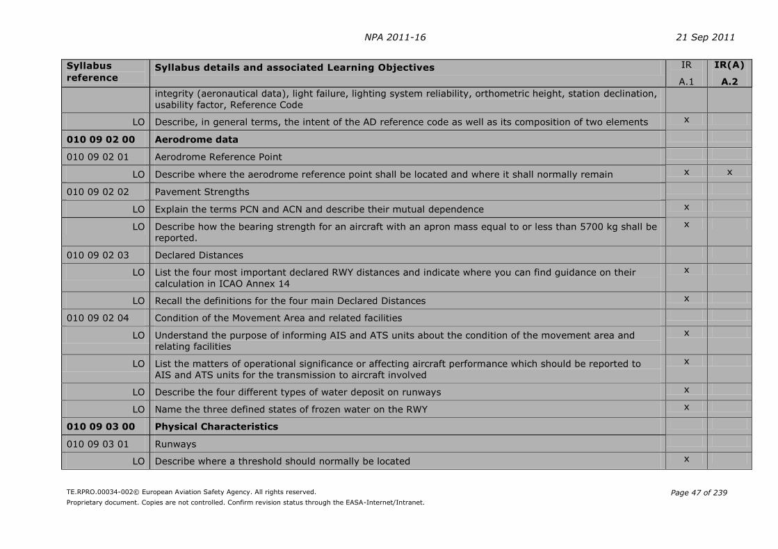
NPA 2011-16 21 Sep 2011
TE.RPRO.00034-002© European Aviation Safety Agency. All rights reserved.
Proprietary document. Copies are not controlled. Confirm revision status through the EASA-Internet/Intranet.
Page 47 of 239
Syllabus
reference Syllabus details and associated Learning Objectives IR
A.1
IR(A)
A.2
integrity (aeronautical data), light failure, lighting system reliability, orthometric height, station declination,
usability factor, Reference Code
LO Describe, in general terms, the intent of the AD reference code as well as its composition of two elements x
010 09 02 00 Aerodrome data
010 09 02 01 Aerodrome Reference Point
LO Describe where the aerodrome reference point shall be located and where it shall normally remain x x
010 09 02 02 Pavement Strengths
LO Explain the terms PCN and ACN and describe their mutual dependence x
LO Describe how the bearing strength for an aircraft with an apron mass equal to or less than 5700 kg shall be
reported.
x
010 09 02 03 Declared Distances
LO List the four most important declared RWY distances and indicate where you can find guidance on their
calculation in ICAO Annex 14
x
LO Recall the definitions for the four main Declared Distances x
010 09 02 04 Condition of the Movement Area and related facilities
LO Understand the purpose of informing AIS and ATS units about the condition of the movement area and
relating facilities
x
LO List the matters of operational significance or affecting aircraft performance which should be reported to
AIS and ATS units for the transmission to aircraft involved
x
LO Describe the four different types of water deposit on runways x
LO Name the three defined states of frozen water on the RWY x
010 09 03 00 Physical Characteristics
010 09 03 01 Runways
LO Describe where a threshold should normally be located x

NPA 2011-16 21 Sep 2011
TE.RPRO.00034-002© European Aviation Safety Agency. All rights reserved.
Proprietary document. Copies are not controlled. Confirm revision status through the EASA-Internet/Intranet.
Page 48 of 239
Syllabus
reference Syllabus details and associated Learning Objectives IR
A.1
IR(A)
A.2
LO Acquaint yourself with the general considerations concerning runways associated with a Stopway or
Clearway
x x
LO State where in Annex 14 you can find detailed information about the required runway width dependent
upon Code number and Code letter
x x
010 09 03 02 Runway Strips
LO Explain the term “Runway strip“ x x
010 09 03 03 Runway end safety area
LO Explain the term “RWY end safety area“ x x
010 09 03 04 Clearway
LO Explain the term “Clearway“ x x
010 09 03 05 Stopway
LO Explain the term “Stopway“ x x
010 09 03 06 Radio-altimeter operating area
LO Describe where a radio-altimeter operating area should be established and how far it should extend laterally
and longitudinally
x
010 09 03 07 Taxiways
LO Describe the condition which must be fulfilled to maintain the required clearance between the outer main
wheels of an aircraft and the edge of the taxiway
x
LO Describe the reasons and the requirements for rapid exit taxiways x
LO State the reason for a taxiway widening in curves x
LO Explain when and where holding bays should be provided x
LO Describe where runway-holding positions shall be established x x
LO Define the term “road-holding position“ x
LO Describe where Intermediate taxi-way holding positions should be established x

NPA 2011-16 21 Sep 2011
TE.RPRO.00034-002© European Aviation Safety Agency. All rights reserved.
Proprietary document. Copies are not controlled. Confirm revision status through the EASA-Internet/Intranet.
Page 49 of 239
Syllabus
reference Syllabus details and associated Learning Objectives IR
A.1
IR(A)
A.2
010 09 04 00 Visual aids for navigation
010 09 04 01 Indicators and signalling devices
LO Describe the wind direction indicators with which ADs shall be equipped x
LO Describe a landing direction indicator x
LO Explain the capabilities of a signalling lamp x
LO State which characteristics a signal area should have x
LO Interpret all indications and signals that may be used in a signals area x
010 09 04 02 Markings
LO Name the colours used for the various markings (RWY, TWY, aircraft stands, apron safety lines) x x
LO State where a RWY designation marking shall be provided and how it is designed x
LO Describe the application and characteristics of: - RWY centre line markings - THR marking x x
- Touchdown Zone marking - RWY side stripe marking - TWY centre line marking - Runway-holding position
marking - Intermediate holding position marking - Aircraft stand markings - Apron safety lines - Road
holding position marking - Mandatory instruction marking - Information marking
010 09 04 03 Lights
LO Describe mechanical safety considerations regarding elevated approach lights and elevated RWY, stopway
and taxiway-lights
x x
LO Discuss the relationship of the intensity of RWY lighting, the approach lighting system and the use of a
separate intensity control for different lighting systems
x x
LO List the conditions for the installation of an AD beacon and describe its general characteristics x x
LO Name the different kinds of operations for which a simple APP lighting system shall be used x x
LO Describe the basic installations of a simple APP lighting system including the dimensions and distances
normally used
x x
LO Describe the principle of a precision APP category l lighting system including such information as location
and characteristics Remark – This includes the ‘Calvert’ system with additional crossbars
x x
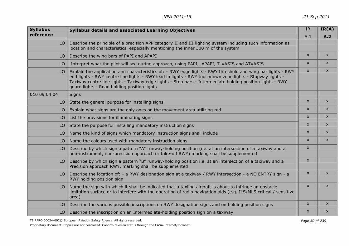
NPA 2011-16 21 Sep 2011
TE.RPRO.00034-002© European Aviation Safety Agency. All rights reserved.
Proprietary document. Copies are not controlled. Confirm revision status through the EASA-Internet/Intranet.
Page 50 of 239
Syllabus
reference Syllabus details and associated Learning Objectives IR
A.1
IR(A)
A.2
LO Describe the principle of a precision APP category II and III lighting system including such information as
location and characteristics, especially mentioning the inner 300 m of the system
LO Describe the wing bars of PAPI and APAPI x x
LO Interpret what the pilot will see during approach, using PAPI, APAPI, T-VASIS and ATVASIS x x
LO Explain the application and characteristics of: - RWY edge lights - RWY threshold and wing bar lights - RWY
end lights - RWY centre line lights - RWY lead in lights - RWY touchdown zone lights - Stopway lights -
Taxiway centre line lights - Taxiway edge lights - Stop bars - Intermediate holding position lights - RWY
guard lights - Road holding position lights
x x
010 09 04 04 Signs
LO State the general purpose for installing signs x x
LO Explain what signs are the only ones on the movement area utilizing red x x
LO List the provisions for illuminating signs x x
LO State the purpose for installing mandatory instruction signs x x
LO Name the kind of signs which mandatory instruction signs shall include x x
LO Name the colours used with mandatory instruction signs x x
LO Describe by which sign a pattern “A“ runway-holding position (i.e. at an intersection of a taxiway and a
non-instrument, non-precision approach or take-off RWY) marking shall be supplemented
x
LO Describe by which sign a pattern “B” runway-holding position i.e. at an intersection of a taxiway and a
Precision approach RWY, marking shall be supplemented
x
LO Describe the location of: - a RWY designation sign at a taxiway / RWY intersection - a NO ENTRY sign - a
RWY holding position sign
x x
LO Name the sign with which it shall be indicated that a taxiing aircraft is about to infringe an obstacle
limitation surface or to interfere with the operation of radio navigation aids (e.g. ILS/MLS critical / sensitive
area)
x x
LO Describe the various possible inscriptions on RWY designation signs and on holding position signs x x
LO Describe the inscription on an Intermediate-holding position sign on a taxiway x x
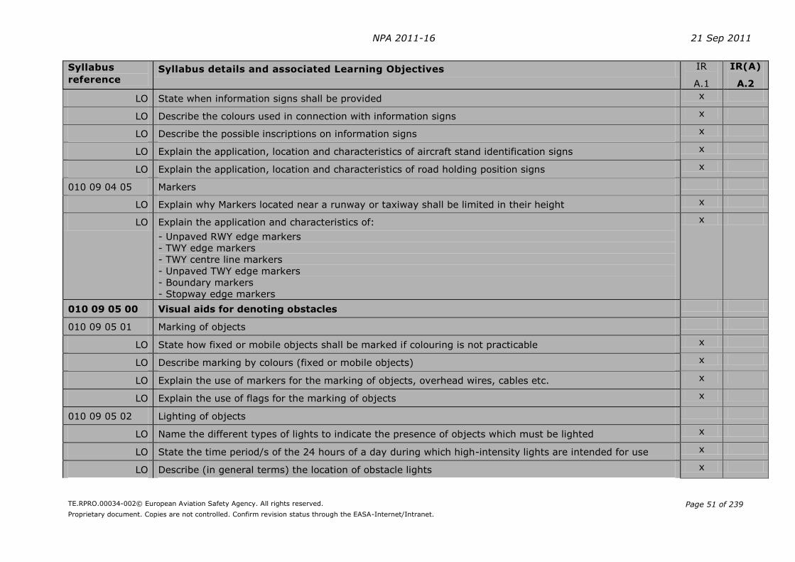
NPA 2011-16 21 Sep 2011
TE.RPRO.00034-002© European Aviation Safety Agency. All rights reserved.
Proprietary document. Copies are not controlled. Confirm revision status through the EASA-Internet/Intranet.
Page 51 of 239
Syllabus
reference Syllabus details and associated Learning Objectives IR
A.1
IR(A)
A.2
LO State when information signs shall be provided x
LO Describe the colours used in connection with information signs x
LO Describe the possible inscriptions on information signs x
LO Explain the application, location and characteristics of aircraft stand identification signs x
LO Explain the application, location and characteristics of road holding position signs x
010 09 04 05 Markers
LO Explain why Markers located near a runway or taxiway shall be limited in their height x
LO Explain the application and characteristics of:
- Unpaved RWY edge markers
- TWY edge markers
- TWY centre line markers
- Unpaved TWY edge markers
- Boundary markers
- Stopway edge markers
x
010 09 05 00 Visual aids for denoting obstacles
010 09 05 01 Marking of objects
LO State how fixed or mobile objects shall be marked if colouring is not practicable x
LO Describe marking by colours (fixed or mobile objects) x
LO Explain the use of markers for the marking of objects, overhead wires, cables etc. x
LO Explain the use of flags for the marking of objects x
010 09 05 02 Lighting of objects
LO Name the different types of lights to indicate the presence of objects which must be lighted x
LO State the time period/s of the 24 hours of a day during which high-intensity lights are intended for use x
LO Describe (in general terms) the location of obstacle lights x
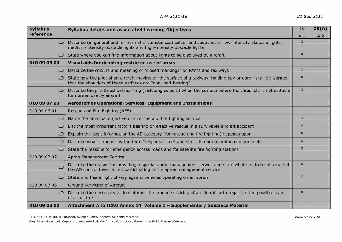
NPA 2011-16 21 Sep 2011
TE.RPRO.00034-002© European Aviation Safety Agency. All rights reserved.
Proprietary document. Copies are not controlled. Confirm revision status through the EASA-Internet/Intranet.
Page 52 of 239
Syllabus
reference Syllabus details and associated Learning Objectives IR
A.1
IR(A)
A.2
LO Describe (in general and for normal circumstances) colour and sequence of low-intensity obstacle lights,
medium-intensity obstacle lights and high-intensity obstacle lights
x
LO State where you can find information about lights to be displayed by aircraft x
010 09 06 00 Visual aids for denoting restricted use of areas
LO Describe the colours and meaning of “closed markings” on RWYs and taxiways x
LO State how the pilot of an aircraft moving on the surface of a taxiway, holding bay or apron shall be warned
that the shoulders of these surfaces are “non-load-bearing”
x
LO Describe the pre-threshold marking (including colours) when the surface before the threshold is not suitable
for normal use by aircraft
x
010 09 07 00 Aerodromes Operational Services, Equipment and Installations
010 09 07 01 Rescue and Fire Fighting (RFF)
LO Name the principal objective of a rescue and fire fighting service x
LO List the most important factors bearing on effective rescue in a survivable aircraft accident x
LO Explain the basic information the AD category (for rescue and fire fighting) depends upon x
LO Describe what is meant by the term “response time“ and state its normal and maximum limits x
LO State the reasons for emergency access roads and for satellite fire fighting stations x
010 09 07 02 Apron Management Service
LO Describe the reason for providing a special apron management service and state what has to be observed if
the AD control tower is not participating in the apron management service
x
LO State who has a right of way against vehicles operating on an apron x
010 09 07 03 Ground Servicing of Aircraft
LO Describe the necessary actions during the ground servicing of an aircraft with regard to the possible event
of a fuel fire
x
010 09 08 00 Attachment A to ICAO Annex 14, Volume 1 – Supplementary Guidance Material
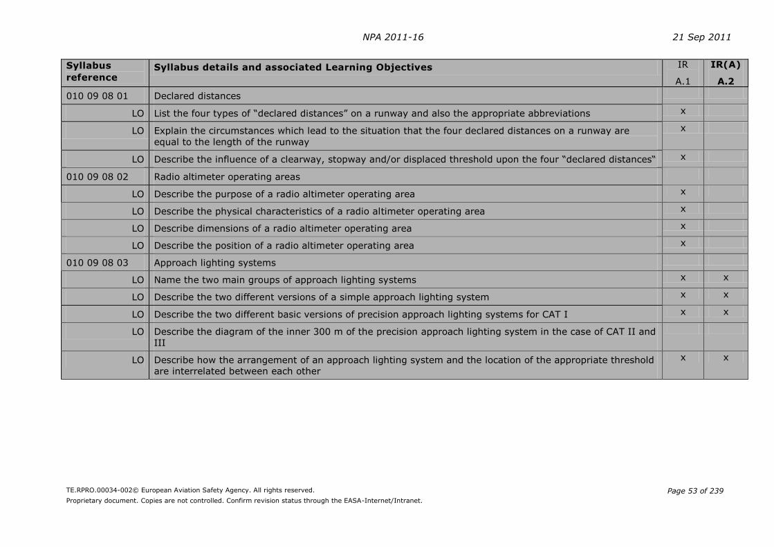
NPA 2011-16 21 Sep 2011
TE.RPRO.00034-002© European Aviation Safety Agency. All rights reserved.
Proprietary document. Copies are not controlled. Confirm revision status through the EASA-Internet/Intranet.
Page 53 of 239
Syllabus
reference Syllabus details and associated Learning Objectives IR
A.1
IR(A)
A.2
010 09 08 01 Declared distances
LO List the four types of “declared distances” on a runway and also the appropriate abbreviations x
LO Explain the circumstances which lead to the situation that the four declared distances on a runway are
equal to the length of the runway
x
LO Describe the influence of a clearway, stopway and/or displaced threshold upon the four “declared distances“ x
010 09 08 02 Radio altimeter operating areas
LO Describe the purpose of a radio altimeter operating area x
LO Describe the physical characteristics of a radio altimeter operating area x
LO Describe dimensions of a radio altimeter operating area x
LO Describe the position of a radio altimeter operating area x
010 09 08 03 Approach lighting systems
LO Name the two main groups of approach lighting systems x x
LO Describe the two different versions of a simple approach lighting system x x
LO Describe the two different basic versions of precision approach lighting systems for CAT I x x
LO Describe the diagram of the inner 300 m of the precision approach lighting system in the case of CAT II and
III
LO Describe how the arrangement of an approach lighting system and the location of the appropriate threshold
are interrelated between each other
x x
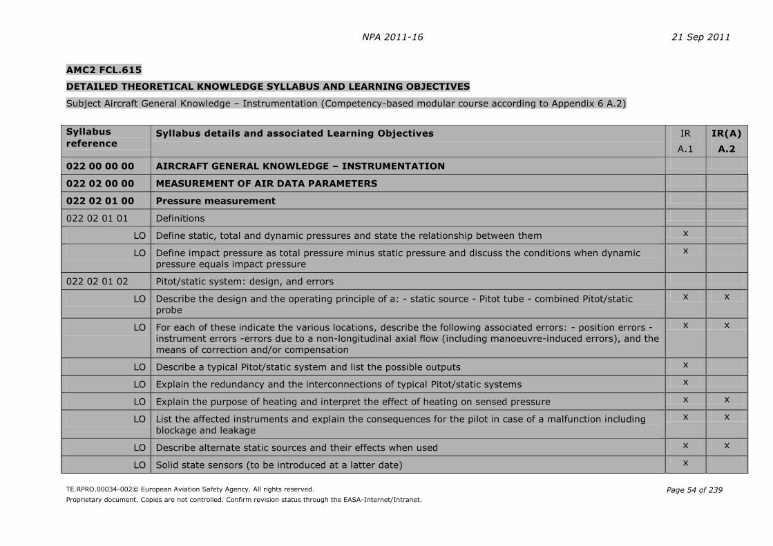
NPA 2011-16 21 Sep 2011
TE.RPRO.00034-002© European Aviation Safety Agency. All rights reserved.
Proprietary document. Copies are not controlled. Confirm revision status through the EASA-Internet/Intranet.
Page 54 of 239
AMC2 FCL.615
DETAILED THEORETICAL KNOWLEDGE SYLLABUS AND LEARNING OBJECTIVES
Subject Aircraft General Knowledge – Instrumentation (Competency-based modular course according to Appendix 6 A.2)
Syllabus
reference Syllabus details and associated Learning Objectives IR
A.1
IR(A)
A.2
022 00 00 00 AIRCRAFT GENERAL KNOWLEDGE – INSTRUMENTATION
022 02 00 00 MEASUREMENT OF AIR DATA PARAMETERS
022 02 01 00 Pressure measurement
022 02 01 01 Definitions
LO Define static, total and dynamic pressures and state the relationship between them x
LO Define impact pressure as total pressure minus static pressure and discuss the conditions when dynamic
pressure equals impact pressure
x
022 02 01 02 Pitot/static system: design, and errors
LO Describe the design and the operating principle of a: - static source - Pitot tube - combined Pitot/static
probe
x x
LO For each of these indicate the various locations, describe the following associated errors: - position errors -
instrument errors -errors due to a non-longitudinal axial flow (including manoeuvre-induced errors), and the
means of correction and/or compensation
x x
LO Describe a typical Pitot/static system and list the possible outputs x
LO Explain the redundancy and the interconnections of typical Pitot/static systems x
LO Explain the purpose of heating and interpret the effect of heating on sensed pressure x x
LO List the affected instruments and explain the consequences for the pilot in case of a malfunction including
blockage and leakage
x x
LO Describe alternate static sources and their effects when used x x
LO Solid state sensors (to be introduced at a latter date) x

NPA 2011-16 21 Sep 2011
TE.RPRO.00034-002© European Aviation Safety Agency. All rights reserved.
Proprietary document. Copies are not controlled. Confirm revision status through the EASA-Internet/Intranet.
Page 55 of 239
Syllabus
reference Syllabus details and associated Learning Objectives IR
A.1
IR(A)
A.2
022 02 02 00 Temperature measurement
022 02 02 01 Definitions
LO Define OAT, SAT, TAT and measured temperature x
022 02 02 02 Design and operation
LO Describe the following types of air temperature probes and their features: - expansion type: Bi-metallic
strip, direct reading - electrical type wire resistance, remote reading
x
LO For each of these indicate the various locations, describe the following associated errors: -position errors -
instrument errors and the means of correction and/or compensation
x
LO Explain the purpose of heating and interpret the effect of heating on sensed temperature x
022 02 04 00 Altimeter
LO Define ISA x
LO List the following two units used for altimeters: - feet - meters and state the relationship between them x
LO Define the following terms: -height, altitude, -indicated altitude, true altitude, -pressure altitude, density
altitude
x x
LO Define the following barometric references: QNH, QFE, 1013,25 hPa x x
LO Explain the operating principles of an altimeter x x
LO Describe and compare the following three types of altimeters: - simple altimeter (single capsule) - sensitive
altimeter (multi capsule) - servo-assisted altimeter
x x
LO Give examples of associated displays: pointer, multi pointer, drum, vertical straight scale x x
LO Describe the following errors: - Pitot/static system errors - temperature error (air column not at ISA
conditions) - time lag (altimeter response to change of height) and the means of correction
x x
LO Give examples of altimeter corrections table from an Aircraft Operations Manual (AOM) x x
LO Describe the effects of a blockage or a leakage on the static pressure line x x
022 02 05 00 Vertical Speed Indicator (VSI)

NPA 2011-16 21 Sep 2011
TE.RPRO.00034-002© European Aviation Safety Agency. All rights reserved.
Proprietary document. Copies are not controlled. Confirm revision status through the EASA-Internet/Intranet.
Page 56 of 239
Syllabus
reference Syllabus details and associated Learning Objectives IR
A.1
IR(A)
A.2
LO List the two units used for VSI: - meters per second - feet per minute and state the relationship between
them
x
LO Explain the operating principles of a VSI x x
LO Describe and compare the following two types of vertical speed indicators: - barometric type - inertial type
(inertial information provided by an Inertial Reference Unit)
x x
LO Describe the following VSI errors: - Pitot/static system errors - time lag and the means of correction x x
LO Describe the effects on a VSI of a blockage or a leakage on the static pressure line x x
LO Give examples of VSI display x
022 02 06 00 Airspeed Indicator (ASI)
LO List the following three units used for airspeed: - Nautical miles/hour (knots) - Statute miles/hour -
Kilometers/hour and state the relationship between them
x
LO Define IAS, CAS, EAS, TAS and state and explain the relationship between these speeds x x
LO Describe the following ASI errors and state when they must be considered: - Pitot/static system errors -
compressibility error - density error
x x
LO Explain the operating principles of an ASI (as appropriate to aeroplanes or helicopters) x x
LO Give examples of ASI display: pointer, vertical straight scale x
LO Interpret ASI corrections tables as used in an Aircraft Operations Manual (AOM) x
LO Describe the effects on an ASI of a blockage or a leak in the static and/or total pressure line(s) x x
022 03 00 00 MAGNETISM – DIRECT READING COMPASS AND FLUX VALVE
022 03 01 00 Earth’s magnetic field
LO Describe the magnetic field of the earth x
LO Explain the properties of a magnet x
LO Define the following terms: - magnetic variation, - magnetic dip (inclination) x
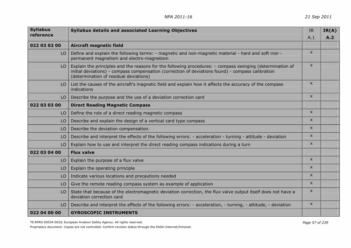
NPA 2011-16 21 Sep 2011
TE.RPRO.00034-002© European Aviation Safety Agency. All rights reserved.
Proprietary document. Copies are not controlled. Confirm revision status through the EASA-Internet/Intranet.
Page 57 of 239
Syllabus
reference Syllabus details and associated Learning Objectives IR
A.1
IR(A)
A.2
022 03 02 00 Aircraft magnetic field
LO Define and explain the following terms: - magnetic and non-magnetic material - hard and soft iron -
permanent magnetism and electro-magnetism
x
LO Explain the principles and the reasons for the following procedures: - compass swinging (determination of
initial deviations) - compass compensation (correction of deviations found) - compass calibration
(determination of residual deviations)
x
LO List the causes of the aircraft's magnetic field and explain how it affects the accuracy of the compass
indications
x
LO Describe the purpose and the use of a deviation correction card x
022 03 03 00 Direct Reading Magnetic Compass
LO Define the role of a direct reading magnetic compass x
LO Describe and explain the design of a vertical card type compass x
LO Describe the deviation compensation. x
LO Describe and interpret the effects of the following errors: - acceleration - turning - attitude - deviation x
LO Explain how to use and interpret the direct reading compass indications during a turn x
022 03 04 00 Flux valve
LO Explain the purpose of a flux valve x
LO Explain the operating principle x
LO Indicate various locations and precautions needed x
LO Give the remote reading compass system as example of application x
LO State that because of the electromagnetic deviation correction, the flux valve output itself does not have a
deviation correction card
x
LO Describe and interpret the effects of the following errors: - acceleration, - turning, - attitude, - deviation x
022 04 00 00 GYROSCOPIC INSTRUMENTS

NPA 2011-16 21 Sep 2011
TE.RPRO.00034-002© European Aviation Safety Agency. All rights reserved.
Proprietary document. Copies are not controlled. Confirm revision status through the EASA-Internet/Intranet.
Page 58 of 239
Syllabus
reference Syllabus details and associated Learning Objectives IR
A.1
IR(A)
A.2
022 04 01 00 Gyroscope: basic principles
LO Define a gyro x x
LO Explain the fundamentals of the theory of gyroscopic forces x x
LO Define the degrees of freedom of a gyro
Remark: As a convention, the degrees of freedom of a gyroscope do not include its own axis of rotation (the
spin axis)
x x
LO Explain the following terms: - rigidity, - precession, - wander (drift/topple) x
LO Distinguish between: - real wander and apparent wander - apparent wander due to the rotation of the Earth
and transport wander
x
LO Describe a free (space) gyro and a tied gyro x
LO Describe and compare electrically and pneumatically driven gyroscopes x
LO Explain the construction and operating principles of a: - rate gyro - rate integrating gyro x
022 04 02 00 Rate of turn indicator /-Turn Co-ordinator – Balance (Slip) Indicator
LO Rate of turn indicator (1) – Turn co-ordinator (2)
LO Explain the purpose of a rate of turn and balance (slip) indicator x x
LO Define a rate-one turn x x
LO Describe the construction and principles of operation of a rate of turn indicator x
LO State the degrees of freedom of a rate of turn indicator x
LO Explain the relation between bank angle, rate of turn and TAS x x
LO Explain why the indication of a rate of turn indicator is only correct for one TAS and when turn is co-
ordinated
x x
LO Explain the purpose of a balance (slip) indicator x x
LO Describe the indications of a rate of turn and balance (slip) indicator during a balanced, slip or skid turn x x

NPA 2011-16 21 Sep 2011
TE.RPRO.00034-002© European Aviation Safety Agency. All rights reserved.
Proprietary document. Copies are not controlled. Confirm revision status through the EASA-Internet/Intranet.
Page 59 of 239
Syllabus
reference Syllabus details and associated Learning Objectives IR
A.1
IR(A)
A.2
LO Describe the construction and principles of operation of a Turn Co-ordinator (or Turn and Bank Indicator) x x
LO Compare the rate of turn indicator and the turn co-ordinator x x
022 04 03 00 Attitude Indicator (Artificial Horizon)
LO Explain the purpose of the attitude indicator x x
LO Describe the different designs and principles of operation of attitude indicators (air driven, electric) x x
LO State the degrees of freedom x
LO Describe the gimbal system x
LO Describe the purpose and principles of operation of the following different erection systems: -air driven
artificial horizon, -electric artificial horizon
x
LO Describe the effects, on the instrument indications, of aircraft acceleration and turns x
LO Describe the attitude display and instrument markings x x
LO Explain the purpose of a vertical gyro unit x
LO List and describe the following components of a vertical gyro unit: - inputs: pitch and roll sensors -
transmission and amplification (synchros and amplifiers) - outputs: display units such as Attitude Direction
Indicator (ADI), Auto Flight Control Systems
x
LO State the advantages and disadvantages of a vertical gyro unit compared to an attitude indicator with
regard to: - design (power source, weight and volume) - accuracy of the information displayed, - availability
of the information for several systems (ADI, AFCS)
x
022 04 04 00 Directional gyroscope
LO Explain the purpose of the directional gyroscope x x
LO Describe the following two types of directional gyroscopes: - Air driven directional gyro - Electric directional
gyro
x x
LO State the degrees of freedom x
LO Describe the gimbal system x

NPA 2011-16 21 Sep 2011
TE.RPRO.00034-002© European Aviation Safety Agency. All rights reserved.
Proprietary document. Copies are not controlled. Confirm revision status through the EASA-Internet/Intranet.
Page 60 of 239
Syllabus
reference Syllabus details and associated Learning Objectives IR
A.1
IR(A)
A.2
LO Define the following different errors: - design and manufacturing imperfections (random wander) - apparent
wander (rotation of the earth) - transport wander (movement relative to the earth’s surface) and explain
their effects
x
LO Calculate the apparent wander (apparent drift rate in degrees per hour) of an uncompensated gyro
according to latitude
x
022 04 05 00 Remote reading compass systems
LO Describe the principles of operation of a remote reading compass system x
LO Using a block diagram, list and explain the function of the following components of a remote reading
compass system: - flux detection unit, - gyro unit, - transducers, precession amplifiers, annunciator -
display unit (compass card, synchronising and set heading knob, DG/compass switch)
x
LO State the advantages and disadvantages of a remote reading compass system compared to a direct reading
magnetic compass with regard to: - design (power source, weight and volume) - deviation due to aircraft
magnetism - turning and acceleration errors - attitude errors - accuracy and stability of the information
displayed, - availability of the information for several systems (Compass card, RMI, AFCS)
x
022 04 06 00 Solid-State Systems – AHRS
LO State that the Micro Electro-Mechanical Sensors (MEMS) technology can be used to make: - solid-state
accelerometers, - solid-state rate sensor gyroscopes, - solid-state magnetometers (measurement of the
earth magnetic field)
x
LO Describe the basic principle of a solid-state Attitude and Heading Reference System (AHRS) using a solid
state 3-axis rate sensor, 3-axis accelerometer and a 3-axis magnetometer
x x
LO Compare the solid state AHRS with the mechanical gyroscope and flux gate system with regard to: - size
and weight, - accuracy, - reliability - cost
x
022 12 00 00 ALERTING SYSTEMS, PROXIMITY SYSTEMS
022 12 07 00 Altitude alert system
LO State the function and describe an Altitude alert system x
LO List and describe the different types of displays and possible alerts x

NPA 2011-16 21 Sep 2011
TE.RPRO.00034-002© European Aviation Safety Agency. All rights reserved.
Proprietary document. Copies are not controlled. Confirm revision status through the EASA-Internet/Intranet.
Page 61 of 239
Syllabus
reference Syllabus details and associated Learning Objectives IR
A.1
IR(A)
A.2
022 12 08 00 Radio-altimeter
LO State the function of a low altitude radio-altimeter x
LO Describe the principle of the distance (height) measurement x
LO State the bandwidth and frequency range used x
LO List the different components of a radio-altimeter and describe the different types of displays x
LO List the systems using the radio-altimeter information x
LO State the range and accuracy of a radio-altimeter x
LO Describe and explain the cable length compensation x
022 12 10 00 ACAS/TCAS principles and operations
LO State that ACAS II is an ICAO standard for anti-collision purposes x
LO State that TCAS II version 7 is compliant with ACAS II standard x
LO Explain that ACAS II is an anti-collision system and does not guarantee any specific separation x
LO Describe the purpose of an ACAS II system as an anti-collision system x
LO Define a Resolution Advisory (RA) and a Traffic Advisory (TA) x
LO State that resolution advisories are calculated in the vertical plane only (climb or descent) x
LO Explain the difference between a corrective RA and a preventive RA (no modification of vertical speed) x
LO Explain that if two aircraft are fitted with an ACAS II, the RA will be co-ordinated x
LO State that ACAS II equipment can take into account several threats simultaneously x
LO State that a detected aircraft without altitude reporting can only generate a Traffic Advisory x
LO Describe the TCAS II system in relation to: - Antenna used. - Computer and links with radio altimeter, air
data computer and mode S transponder
x
LO Identify the inputs and outputs of TCAS II x

NPA 2011-16 21 Sep 2011
TE.RPRO.00034-002© European Aviation Safety Agency. All rights reserved.
Proprietary document. Copies are not controlled. Confirm revision status through the EASA-Internet/Intranet.
Page 62 of 239
Syllabus
reference Syllabus details and associated Learning Objectives IR
A.1
IR(A)
A.2
LO Explain the principle of TCAS II interrogations x
LO State that standard detection range is approximately 30 NM x
LO State that the normal interrogation period is 1 second x
LO Explain the principle of "reduced surveillance" x
LO Explain that in high density traffic areas the period can be extended to 5 seconds and the transmission
power reduction can reduce the range detection down to 5 NM
x
LO Identify the equipment, which an intruder must be fitted with in order to be detected by TCAS II x
LO Explain the anti collision process: - that the criteria used to trigger an alarm (TA or RA) are the time to
reach the Closest Point of Approach, called TAU, and the difference of altitude. - that an intruder will be
classified as Proximate when being less than 6 NM and 1200 ft from the TCAS equipped aircraft - that the
limit time to CPA is different depending on aircraft altitude, linked to a sensitivity level (SL) and state that
the value to trigger a RA is from 15 to 35 seconds. - that, in case of RA, the intended vertical separation
varies from 300 to 600 ft (700 ft above FL420), depending on the SL - that below 1000 ft above ground, no
RA can be generated - that below 1450 ft (radio altimeter value) "Increase descent" RA is inhibited. - that,
in high altitude, performances of the type of aircraft are taken in account to inhibit "Climb" and "Increase
Climb" RA
x
LO List and interpret the following information available from TCAS: - the different possible status for a
detected aircraft: other, proximate, intruder - the appropriate graphic symbols and their position on the
horizontal display. - different aural warnings
x
LO Explain that a RA is presented as a possible vertical speed, on a TCAS indicator or on the Primary Flight
Display
x
LO Describe the possible presentation of a RA, on a VSI or on PFD x
LO Explain that the pilot must not interpret the horizontal track of an intruder upon the display x
022 13 00 00 INTEGRATED INSTRUMENTS – ELECTRONIC DISPLAYS
022 13 01 00 Electronic display units
022 13 01 01 Design, limitations

NPA 2011-16 21 Sep 2011
TE.RPRO.00034-002© European Aviation Safety Agency. All rights reserved.
Proprietary document. Copies are not controlled. Confirm revision status through the EASA-Internet/Intranet.
Page 63 of 239
Syllabus
reference Syllabus details and associated Learning Objectives IR
A.1
IR(A)
A.2
LO
List the different technologies used e.g. CRT and LCD and the associated limitations:
- cockpit temperature
- glare
x x
022 13 02 00 Mechanical Integrated instruments: ADI/HSI
LO Describe an Attitude and Director Indicator (ADI) and a Horizontal Situation Indicator (HSI) x x
LO List all the information that can be displayed for either instruments x x
022 13 03 00 Electronic Flight Instrument Systems (EFIS)
022 13 03 01 Design, operation
LO List and describe the different components of an EFIS x x
LO
List the following possible inputs and outputs of an EFIS:
- control panel
- display units
- symbol generator
- remote light sensor
x
LO Describe the function of the symbol generator unit x
022 13 03 02 Primary Flight Display (PFD), Electronic Attitude Director Indicator (EADI)
LO State that a PFD (or an EADI) presents a dynamic colour display of all the parameters necessary to control
the aircraft
x x
LO List and describe the following information that can be displayed on the Primary Flight Display (PFD) unit of
an aircraft:
- Flight Mode Annunciation
- basic T:
- attitude
- IAS
- altitude
- heading/track indications
- vertical speed
- maximum airspeed warning
x x

NPA 2011-16 21 Sep 2011
TE.RPRO.00034-002© European Aviation Safety Agency. All rights reserved.
Proprietary document. Copies are not controlled. Confirm revision status through the EASA-Internet/Intranet.
Page 64 of 239
Syllabus
reference Syllabus details and associated Learning Objectives IR
A.1
IR(A)
A.2
- selected airspeed
- speed trend vector
- selected altitude
- current barometric reference
- steering indications (FD command bars)
- selected heading
- Flight Path Vector (FPV)
- Radio altitude
- Decision height
- ILS indications
- ACAS (TCAS) indications
- failure flags and messages
022 13 03 03 Navigation Display (ND), Electronic Horizontal Situation Indicator (EHSI)
LO State that a ND (or an EHSI) provides a mode-selectable colour flight navigation display x x
LO List and describe the following four modes displayed on a Navigation Display (ND) unit: - MAP (or ARC): -
VOR (or ROSE VOR) - APP (or ROSE LS) - PLAN
x x
LO List and explain the following information that can be displayed with the MAP (or ARC) mode on a
Navigation Display (ND) unit:
- Selected and current track
- Selected and current heading (magnetic or true north reference)
- Cross track error
- Origin and destination airport with runway selected
- Bearings To or From the tuned and selected stations
- Active and/or secondary flight plan
- Range marks
- Ground speed
- TAS and Ground Speed
- Wind direction and speed
- Next waypoint distance and estimated time of arrival
x x

NPA 2011-16 21 Sep 2011
TE.RPRO.00034-002© European Aviation Safety Agency. All rights reserved.
Proprietary document. Copies are not controlled. Confirm revision status through the EASA-Internet/Intranet.
Page 65 of 239
Syllabus
reference Syllabus details and associated Learning Objectives IR
A.1
IR(A)
A.2
- Additional navigation facilities (STA), waypoint (WPT) and airports (ARPT)
- Weather radar information
- Traffic information from the ACAS (TCAS)
- Terrain information from the TAWS or HTAWS (EGPWS)
- Failure flags and messages
LO List and explain the following information that can be displayed with the VOR/APP (or ROSE VOR/ROSE LS)
mode on a Navigation Display (ND) unit: - selected and current track, - selected and current heading
(magnetic or true north reference), - VOR course or ILS localizer course. - VOR (VOR or ROSE VOR mode)
or LOC course deviation (APP or ROSE LS) - Glide Slope pointer (APP or ROSE LS) - Frequency or identifier
of the tuned station. - ground speed - TAS and Ground Speed - Wind direction and speed - Failure flags and
messages
x x
LO Give examples of possible transfers between units x
LO Give examples of EFIS control panels x

NPA 2011-16 21 Sep 2011
TE.RPRO.00034-002© European Aviation Safety Agency. All rights reserved.
Proprietary document. Copies are not controlled. Confirm revision status through the EASA-Internet/Intranet.
Page 66 of 239
AMC3 FCL.615
DETAILED THEORETICAL KNOWLEDGE SYLLABUS AND LEARNING OBJECTIVES Subject Flight Planning and Flight Monitoring (Competency-based modular course according to Appendix 6 A.2) Syllabus
reference Syllabus details and associated Learning Objectives IR
A.1
IR(A)
A.2
033 00 00 00 FLIGHT PLANNING AND FLIGHT MONITORING
033 02 00 00 FLIGHT PLANNING FOR IFR FLIGHTS
033 02 01 00 IFR Navigation plan
033 02 01 01 Airways and routes
LO Select the preferred airway(s) or route(s) considering: - Altitudes and Flight levels - Standard routes - ATC restrictions - Shortest distance - Obstacles - Any other relevant data
x x
033 02 01 02 Courses and distances from en-route charts
LO Determine courses and distances x x
LO Determine bearings and distances of waypoints from radio navigation aids x x
033 02 01 03 Altitudes
LO Define the following altitudes: - Minimum En-route Altitude (MEA) - Minimum Obstacle Clearance Altitude (MOCA) - Minimum Off Route Altitude (MORA) - Grid Minimum Off-Route Altitude (Grid MORA) - Maximum Authorised Altitude (MAA) - Minimum Crossing Altitude (MCA) - Minimum Holding Altitude (MHA)
x x
LO Extract the following altitudes from the chart(s): - Minimum En-route Altitude (MEA) - Minimum Obstacle Clearance Altitude (MOCA) - Minimum Off Route Altitude (MORA)
x x
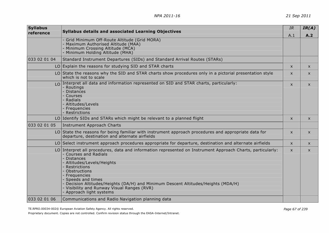
NPA 2011-16 21 Sep 2011
TE.RPRO.00034-002© European Aviation Safety Agency. All rights reserved.
Proprietary document. Copies are not controlled. Confirm revision status through the EASA-Internet/Intranet.
Page 67 of 239
Syllabus
reference Syllabus details and associated Learning Objectives IR
A.1
IR(A)
A.2 - Grid Minimum Off-Route Altitude (Grid MORA) - Maximum Authorised Altitude (MAA) - Minimum Crossing Altitude (MCA) - Minimum Holding Altitude (MHA)
033 02 01 04 Standard Instrument Departures (SIDs) and Standard Arrival Routes (STARs)
LO Explain the reasons for studying SID and STAR charts x x
LO State the reasons why the SID and STAR charts show procedures only in a pictorial presentation style which is not to scale
x x
LO Interpret all data and information represented on SID and STAR charts, particularly: - Routings - Distances - Courses - Radials - Altitudes/Levels - Frequencies - Restrictions
x x
LO Identify SIDs and STARs which might be relevant to a planned flight x x
033 02 01 05 Instrument Approach Charts
LO State the reasons for being familiar with instrument approach procedures and appropriate data for departure, destination and alternate airfields
x x
LO Select instrument approach procedures appropriate for departure, destination and alternate airfields x x
LO Interpret all procedures, data and information represented on Instrument Approach Charts, particularly: - Courses and Radials - Distances - Altitudes/Levels/Heights - Restrictions - Obstructions - Frequencies - Speeds and times - Decision Altitudes/Heights (DA/H) and Minimum Descent Altitudes/Heights (MDA/H) - Visibility and Runway Visual Ranges (RVR) - Approach light systems
x x
033 02 01 06 Communications and Radio Navigation planning data
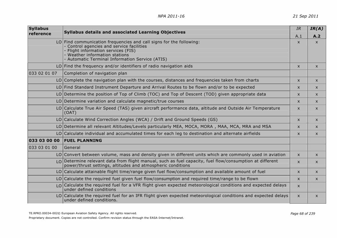
NPA 2011-16 21 Sep 2011
TE.RPRO.00034-002© European Aviation Safety Agency. All rights reserved.
Proprietary document. Copies are not controlled. Confirm revision status through the EASA-Internet/Intranet.
Page 68 of 239
Syllabus
reference Syllabus details and associated Learning Objectives IR
A.1
IR(A)
A.2
LO Find communication frequencies and call signs for the following: - Control agencies and service facilities - Flight information services (FIS) - Weather information stations - Automatic Terminal Information Service (ATIS)
x x
LO Find the frequency and/or identifiers of radio navigation aids x x
033 02 01 07 Completion of navigation plan
LO Complete the navigation plan with the courses, distances and frequencies taken from charts x x
LO Find Standard Instrument Departure and Arrival Routes to be flown and/or to be expected x x
LO Determine the position of Top of Climb (TOC) and Top of Descent (TOD) given appropriate data x x
LO Determine variation and calculate magnetic/true courses x x
LO Calculate True Air Speed (TAS) given aircraft performance data, altitude and Outside Air Temperature (OAT)
x x
LO Calculate Wind Correction Angles (WCA) / Drift and Ground Speeds (GS) x x
LO Determine all relevant Altitudes/Levels particularly MEA, MOCA, MORA , MAA, MCA, MRA and MSA x x
LO Calculate individual and accumulated times for each leg to destination and alternate airfields x x
033 03 00 00 FUEL PLANNING
033 03 01 00 General
LO Convert between volume, mass and density given in different units which are commonly used in aviation x x
LO Determine relevant data from flight manual, such as fuel capacity, fuel flow/consumption at different power/thrust settings, altitudes and atmospheric conditions
x x
LO Calculate attainable flight time/range given fuel flow/consumption and available amount of fuel x x
LO Calculate the required fuel given fuel flow/consumption and required time/range to be flown x x
LO Calculate the required fuel for a VFR flight given expected meteorological conditions and expected delays under defined conditions
x
LO Calculate the required fuel for an IFR flight given expected meteorological conditions and expected delays under defined conditions.
x x

NPA 2011-16 21 Sep 2011
TE.RPRO.00034-002© European Aviation Safety Agency. All rights reserved.
Proprietary document. Copies are not controlled. Confirm revision status through the EASA-Internet/Intranet.
Page 69 of 239
Syllabus
reference Syllabus details and associated Learning Objectives IR
A.1
IR(A)
A.2
033 04 00 00 PRE-FLIGHT PREPARATION
033 04 01 00 NOTAM briefing
033 04 01 01 Ground facilities and services
LO Check that ground facilities and services required for the planned flight are available and adequate x x
033 04 01 02 Departure, destination and alternate aerodromes
LO Find and analyse the latest state at the departure, destination and alternate aerodromes, in particular for: - Opening hours - Work in Progress (WIP) - Special procedures due to Work in Progress (WIP) - Obstructions - Changes of frequencies for communications, navigation aids and facilities
x x
033 04 01 03 Airway routings and airspace structure
LO Find and analyse the latest en-route state for: - Airway(s) or Route(s) - Restricted, Dangerous and Prohibited areas - Changes of frequencies for communications, navigation aids and facilities
x x
033 04 02 00 Meteorological briefing
033 04 02 02 Update of navigation plan using the latest meteorological information:
LO Confirm the optimum altitude/FL given wind, temperature and aircraft data x x
LO Confirm true altitudes to ensure that statutory minimum clearance is attained given atmospheric data x
LO Confirm magnetic headings and ground speeds x x
LO Confirm the individual leg times and the total time en route x x
LO Confirm the total time en route for the trip to the destination x x
LO Confirm the total time from destination to the alternate airfield x x
033 04 02 05 Update of fuel log
LO Calculate revised fuel data in accordance with changed conditions x x

NPA 2011-16 21 Sep 2011
TE.RPRO.00034-002© European Aviation Safety Agency. All rights reserved.
Proprietary document. Copies are not controlled. Confirm revision status through the EASA-Internet/Intranet.
Page 70 of 239
Syllabus
reference Syllabus details and associated Learning Objectives IR
A.1
IR(A)
A.2
033 05 00 00 ICAO FLIGHT PLAN (ATS Flight Plan)
033 05 01 00 Individual Flight Plan
033 05 01 01 Format of Flight Plan
LO State the reasons for a fixed format of an ICAO ATS Flight Plan (FPL) x x
LO Determine the correct entries to complete an FPL plus decode and interpret the entries in a completed FPL, particularly for the following: - Aircraft identification (Item 7) - Flight rules and type of flight (Item 8) - Number and type of aircraft and wake turbulence category (Item 9) - Equipment (Item 10) - Departure aerodrome and time (Item 13) - Route (Item 15) - Destination aerodrome, total estimated elapsed time and Alternate aerodrome (Item 16) - Other information (Item 18) - Supplementary Information (Item 19)
x x
033 05 01 02 Completion of an ATS Flight Plan (FPL)
LO Complete the Flight Plan using information from the following: - Navigation plan - Fuel plan - Operator’s records for basic aircraft information
x x
033 05 03 00 Submission of an ATS Flight Plan (FPL)
LO Explain the requirements for the submission of an ATS Flight Plan x x
LO Explain the actions to be taken in case of Flight Plan changes x x
LO State the actions to be taken in case of inadvertent changes to Track, TAS and time estimate affecting the current Flight Plan
x x
LO Explain the procedures for closing a Flight Plan x x
033 06 00 00 FLIGHT MONITORING AND IN-FLIGHT RE-PLANNING
033 06 01 00 Flight monitoring
033 06 01 01 Monitoring of track and time
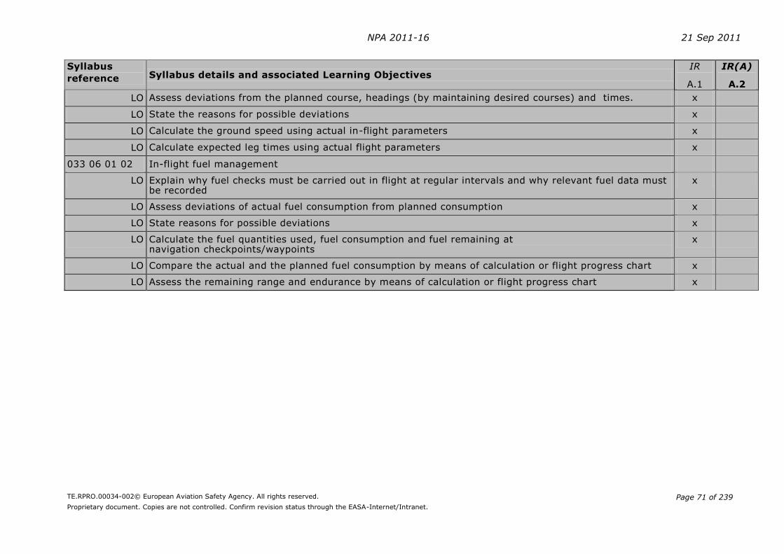
NPA 2011-16 21 Sep 2011
TE.RPRO.00034-002© European Aviation Safety Agency. All rights reserved.
Proprietary document. Copies are not controlled. Confirm revision status through the EASA-Internet/Intranet.
Page 71 of 239
Syllabus
reference Syllabus details and associated Learning Objectives IR
A.1
IR(A)
A.2
LO Assess deviations from the planned course, headings (by maintaining desired courses) and times. x
LO State the reasons for possible deviations x
LO Calculate the ground speed using actual in-flight parameters x
LO Calculate expected leg times using actual flight parameters x
033 06 01 02 In-flight fuel management
LO Explain why fuel checks must be carried out in flight at regular intervals and why relevant fuel data must be recorded
x
LO Assess deviations of actual fuel consumption from planned consumption x
LO State reasons for possible deviations x
LO Calculate the fuel quantities used, fuel consumption and fuel remaining at navigation checkpoints/waypoints
x
LO Compare the actual and the planned fuel consumption by means of calculation or flight progress chart x
LO Assess the remaining range and endurance by means of calculation or flight progress chart x
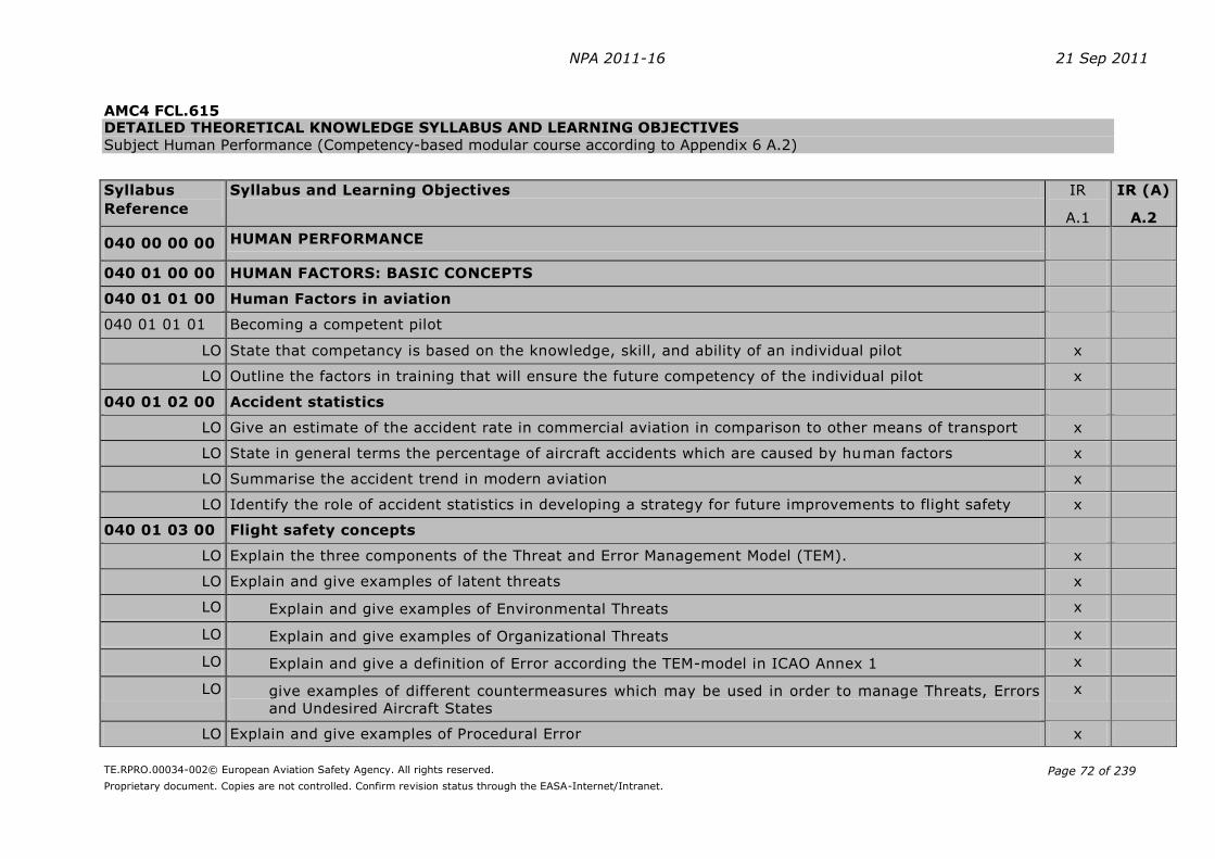
NPA 2011-16 21 Sep 2011
TE.RPRO.00034-002© European Aviation Safety Agency. All rights reserved.
Proprietary document. Copies are not controlled. Confirm revision status through the EASA-Internet/Intranet.
Page 72 of 239
AMC4 FCL.615 DETAILED THEORETICAL KNOWLEDGE SYLLABUS AND LEARNING OBJECTIVES Subject Human Performance (Competency-based modular course according to Appendix 6 A.2)
Syllabus
Reference
Syllabus and Learning Objectives IR
A.1
IR (A)
A.2
040 00 00 00 HUMAN PERFORMANCE
040 01 00 00 HUMAN FACTORS: BASIC CONCEPTS
040 01 01 00 Human Factors in aviation
040 01 01 01 Becoming a competent pilot
LO State that competancy is based on the knowledge, skill, and ability of an individual pilot x
LO Outline the factors in training that will ensure the future competency of the individual pilot x
040 01 02 00 Accident statistics
LO Give an estimate of the accident rate in commercial aviation in comparison to other means of transport x
LO State in general terms the percentage of aircraft accidents which are caused by human factors x
LO Summarise the accident trend in modern aviation x
LO Identify the role of accident statistics in developing a strategy for future improvements to flight safety x
040 01 03 00 Flight safety concepts
LO Explain the three components of the Threat and Error Management Model (TEM). x
LO Explain and give examples of latent threats x
LO Explain and give examples of Environmental Threats x
LO Explain and give examples of Organizational Threats x
LO Explain and give a definition of Error according the TEM-model in ICAO Annex 1 x
LO give examples of different countermeasures which may be used in order to manage Threats, Errors
and Undesired Aircraft States
x
LO Explain and give examples of Procedural Error x
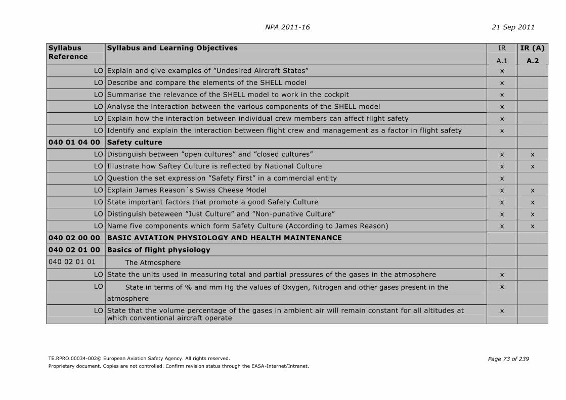
NPA 2011-16 21 Sep 2011
TE.RPRO.00034-002© European Aviation Safety Agency. All rights reserved.
Proprietary document. Copies are not controlled. Confirm revision status through the EASA-Internet/Intranet.
Page 73 of 239
Syllabus
Reference
Syllabus and Learning Objectives IR
A.1
IR (A)
A.2
LO Explain and give examples of ”Undesired Aircraft States” x
LO Describe and compare the elements of the SHELL model x
LO Summarise the relevance of the SHELL model to work in the cockpit x
LO Analyse the interaction between the various components of the SHELL model x
LO Explain how the interaction between individual crew members can affect flight safety x
LO Identify and explain the interaction between flight crew and management as a factor in flight safety x
040 01 04 00 Safety culture
LO Distinguish between ”open cultures” and ”closed cultures” x x
LO Illustrate how Saftey Culture is reflected by National Culture x x
LO Question the set expression ”Safety First” in a commercial entity x
LO Explain James Reason´s Swiss Cheese Model x x
LO State important factors that promote a good Safety Culture x x
LO Distinguish beteween ”Just Culture” and ”Non-punative Culture” x x
LO Name five components which form Safety Culture (According to James Reason) x x
040 02 00 00 BASIC AVIATION PHYSIOLOGY AND HEALTH MAINTENANCE
040 02 01 00 Basics of flight physiology
040 02 01 01 The Atmosphere
LO State the units used in measuring total and partial pressures of the gases in the atmosphere x
LO State in terms of % and mm Hg the values of Oxygen, Nitrogen and other gases present in the
atmosphere
x
LO State that the volume percentage of the gases in ambient air will remain constant for all altitudes at which conventional aircraft operate
x

NPA 2011-16 21 Sep 2011
TE.RPRO.00034-002© European Aviation Safety Agency. All rights reserved.
Proprietary document. Copies are not controlled. Confirm revision status through the EASA-Internet/Intranet.
Page 74 of 239
Syllabus
Reference
Syllabus and Learning Objectives IR
A.1
IR (A)
A.2
LO State the physiological significance of the following laws:
- Boyle’s Law
- Dalton’s Law
- Henry’s Laws - The General Gas Law
x
LO State the ICAO standard temperature at Mean Sea Level and the Standard Temperature Lapse Rate x
LO State at what approximate altitudes in the standard atmosphere the atmospheric pressure will
be ¼, ½ and ¾ of MSL pressure
x
LO State the effects of increasing altitude on the overall pressure and partial pressures of the various gases
in the atmosphere
x
LO Explain the differences in gas expansion between alveolar and ambient air when climbing x
LO State the condition required for human beings to be able to survive at any given altitude x
LO State and explain the importance of partial pressure x
040 02 01 02 Respiratory and circulatory systems
LO List the main components of the respiratory system and their function x
LO Identify the different volumes of air in the lungs and state the normal respiratory rate x
LO State how oxygen and carbon dioxide are transported throughout the body x
LO Explain the process by which oxygen is transferred to the tissues and carbon dioxide is eliminated from the body and the oxygen requirement of tissues
x
LO Explain the role of carbon dioxide in the control and regulation of respiration x
LO Describe the basic processes of external respiration and internal respiration x
LO List the factors determining pulse rate x
LO Name the major components of the circulatory system and describe their function x

NPA 2011-16 21 Sep 2011
TE.RPRO.00034-002© European Aviation Safety Agency. All rights reserved.
Proprietary document. Copies are not controlled. Confirm revision status through the EASA-Internet/Intranet.
Page 75 of 239
Syllabus
Reference
Syllabus and Learning Objectives IR
A.1
IR (A)
A.2
LO State the values for a normal pulse rate and the average cardiac output (heart rate x stroke volume) of an adult at rest
x
LO Name the four chambers of the heart and state the function of the individual chambers x
LO Differentiate between arteries, veins, and capillaries in their structure and function x
LO State the functions of the coronary arteries and veins x
LO Define ‘systolic’ and ‘diastolic’ blood pressure x
LO State the normal blood pressure ranges and units of measurement x
LO State that in an average pilot blood pressure will rise slightly with age as the arteries lose their elasticity x
LO List the main constituents of the blood and describe their functions x
LO Stress the function of haemoglobin in the circulatory system x
LO Define ‘anaemia’ and state its common causes x
LO Indicate the effect of increasing altitude on haemoglobin oxygen saturation x
Hypertension and Hypotension
LO Define 'hypertension' and ‘hypotension’ x
LO List the effects that high and low blood pressure will have on some normal functions of the human body
x
LO State that both hypotension and hypertension may disqualify the pilot from obtaining a medical clearance to fly
x
LO List the factors which can lead to hypertension in an individual x
LO State the corrective actions that may be taken to reduce high blood pressure x
LO Stress that hypertension is the major factor of ‘strokes’ in the general population x
Coronary artery disease
LO Differentiate between ‘angina’ and ‘heart attack’ x
LO Explain the major risk factors for coronary disease x

NPA 2011-16 21 Sep 2011
TE.RPRO.00034-002© European Aviation Safety Agency. All rights reserved.
Proprietary document. Copies are not controlled. Confirm revision status through the EASA-Internet/Intranet.
Page 76 of 239
Syllabus
Reference
Syllabus and Learning Objectives IR
A.1
IR (A)
A.2
LO State the role played by physical exercise in reducing the chances of developing coronary disease x
Hypoxia
LO Define the two major forms of hypoxia (hypoxic and anaemic) and the common causes of both x
LO State the symptoms of Hypoxia x
LO State why living tissues require oxygen x
LO State that healthy people are able to compensate for altitudes up to approximately 10,000 - 12,000 ft x
LO Name the three physiological thresholds and allocate the corresponding altitudes for each of them x
LO State the altitude at which short term memory begins to be affected by hypoxia x
LO Define the terms 'Time of Useful Consciousness' (TUC) x
LO State the TUC varies between individuals but the approximate values are:
For a person seated (at rest) For a person moderately active
20,000 ft 30min 5min
30,000 ft 1-2min not required
35,000 ft 30-90sec not required
40,000 ft 15-20sec not required
x
LO Explain the dangers of flying above10,000 ft without using additional oxygen or being in a pressurized
cabin
x
LO List the factors determining the severity of hypoxia x
LO State the precautions to be taken when giving blood x
LO State the equivalent altitudes when breathing ambient air and 100% oxygen for MSL and approximately 10,000 ft, 30,000 ft and 40,000 ft
x
Hyperventilation
LO Describe the role of carbon dioxide in hyperventilation x

NPA 2011-16 21 Sep 2011
TE.RPRO.00034-002© European Aviation Safety Agency. All rights reserved.
Proprietary document. Copies are not controlled. Confirm revision status through the EASA-Internet/Intranet.
Page 77 of 239
Syllabus
Reference
Syllabus and Learning Objectives IR
A.1
IR (A)
A.2
LO Define the term 'hyperventilation' x
LO List the factors causing hyperventilation x
LO State that hyperventilation may be caused by psychological or physiological reasons x
LO List the signs and symptoms of hyperventilation x
LO Describe the effects of hyperventilation on muscular coordination x
LO List measures which may be taken to counteract hyperventilation x
Decompression Sickness/Illness
LO State the normal range of cabin pressure altitude in pressurized commercial aircraft and describe its protective function for aircrew and passengers
x
LO Identify the causes of decompression sickness in flight operation x
LO State how decompression sickness can be prevented x
LO State the threshold for the onset of decompression sickness in terms of altitude x
LO State the approximate altitude above which DCS is likely to occur x
LO List the symptoms of decompression sickness x
LO Indicate how decompression sickness may be treated x
LO List the vital actions the crew has to perform when cabin pressurisation is lost x
LO Define the hazards of diving and flying and give the recommendations associated with these activities x
Acceleration
LO Define 'linear', 'angular' and 'radial acceleration' x x
LO Describe the effects of acceleration on the circulation and blood volume distribution x x
LO List the factors determining the effects of acceleration on the human body x x
LO Describe measures which may be taken to increase tolerance to positive acceleration x x
LO List the effects of positive acceleration with respect to type, sequence and the corresponding G-load x x

NPA 2011-16 21 Sep 2011
TE.RPRO.00034-002© European Aviation Safety Agency. All rights reserved.
Proprietary document. Copies are not controlled. Confirm revision status through the EASA-Internet/Intranet.
Page 78 of 239
Syllabus
Reference
Syllabus and Learning Objectives IR
A.1
IR (A)
A.2
Carbon Monoxide
LO State how carbon monoxide may be produced x
LO State how the presence of carbon monoxide in the blood affects the distribution of oxygen x
LO List the signs and symptoms of carbon monoxide poisoning x
LO Indicate how carbon monoxide poisoning can be treated and counter-measures that can be adopted x
040 02 02 00 Man and Environment: the sensory system
LO List the different senses x x
LO State the multi-sensory nature of human perception x x
040 02 02 01 Central, peripheral and autonomic nervous systems
LO Name the main parts of the central nervous system x
LO State the basic functions of the Central Nervous System (CNS), the Peripheral Nervous System (PNS) and the Autonomic (Vegetative) System (ANS)
x
LO Discuss broadly how information is processed by the nervous systems and the role of reflexes x
LO Define the division of the peripheral nerves into sensory and motor nerves x
LO State that a nerve impulse is an electro-chemical phenomenon x
LO Define the term ‘sensory threshold’ x
LO Define the term ‘sensitivity’, especially in the context of vision x
LO Give examples of sensory adaptation x
LO Define the term ‘habituation’ and state its implication for flight safety x
LO Define biological control systems as neuro-hormonal processes that are highly self regulated in the normal environment
x
040 02 02 02 Vision
Functional anatomy
LO Name the most important parts of the eye and the pathway to the visual cortex x

NPA 2011-16 21 Sep 2011
TE.RPRO.00034-002© European Aviation Safety Agency. All rights reserved.
Proprietary document. Copies are not controlled. Confirm revision status through the EASA-Internet/Intranet.
Page 79 of 239
Syllabus
Reference
Syllabus and Learning Objectives IR
A.1
IR (A)
A.2
LO State the basic functions of the parts of the eye x
LO Define ‘accommodation’ x
LO Distinguish between the functions of the rod and cone cells x
LO Describe the distribution of rod and cone cells in the retina and explain their relevance on vision x
Visual foveal and peripheral vision
LO Explain the terms ‘visual acuity’, ‘visual field’, ‘central vision’, ‘peripheral vision’, 'fovea' and explain their function in the process of vision
x
LO List the factors which may degrade visual acuity and the importance of ‘lookout’ x
LO State the limitations of night vision and the different scanning techniques by both night and day (regularly spaced eye movements each covering an overlapping sector of about 10º)
x
LO Explain the adaptation mechanism in vision to cater for reduced and increased levels of illumination x
LO State the time necessary for the eye to adapt both to the dark and bright light x
LO State the effect of hypoxia and smoking on night vision x
LO Explain the nature of colour blindness and the significance of the ‘blind spot’ on the retina in detecting other traffic in flight
x
Binocular and monocular vision
LO Distinguish between monocular and binocular vision x
LO Explain the basis of depth perception and its relevance to flight performance x
LO List possible monocular cues for depth perception x
LO State the problems of vision associated with higher energy blue light and ultra violet rays x
Defective vision
LO Explain long sightedness, short sightedness and Astigmatism x
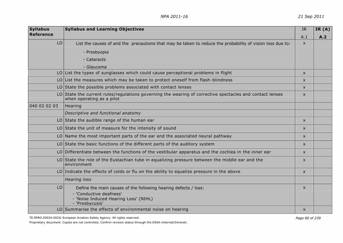
NPA 2011-16 21 Sep 2011
TE.RPRO.00034-002© European Aviation Safety Agency. All rights reserved.
Proprietary document. Copies are not controlled. Confirm revision status through the EASA-Internet/Intranet.
Page 80 of 239
Syllabus
Reference
Syllabus and Learning Objectives IR
A.1
IR (A)
A.2
LO List the causes of and the precautions that may be taken to reduce the probability of vision loss due to:
- Presbyopia
- Cataracts
- Glaucoma
x
LO List the types of sunglasses which could cause perceptional problems in flight x
LO List the measures which may be taken to protect oneself from flash-blindness x
LO State the possible problems associated with contact lenses x
LO State the current rules/regulations governing the wearing of corrective spectacles and contact lenses when operating as a pilot
x
040 02 02 03 Hearing
Descriptive and functional anatomy
LO State the audible range of the human ear x
LO State the unit of measure for the intensity of sound x
LO Name the most important parts of the ear and the associated neural pathway x
LO State the basic functions of the different parts of the auditory system x
LO Differentiate between the functions of the vestibular apparatus and the cochlea in the inner ear x
LO State the role of the Eustachian tube in equalizing pressure between the middle ear and the environment
x
LO Indicate the effects of colds or flu on the ability to equalize pressure in the above x
Hearing loss
LO Define the main causes of the following hearing defects / loss:
- 'Conductive deafness' - 'Noise Induced Hearing Loss' (NIHL) - 'Presbycusis'
x
LO Summarise the effects of environmental noise on hearing x

NPA 2011-16 21 Sep 2011
TE.RPRO.00034-002© European Aviation Safety Agency. All rights reserved.
Proprietary document. Copies are not controlled. Confirm revision status through the EASA-Internet/Intranet.
Page 81 of 239
Syllabus
Reference
Syllabus and Learning Objectives IR
A.1
IR (A)
A.2
LO State the decibel level of received noise that will cause NIHL x
LO Indicate the factors, other than noise level, which may lead to NIHL x
LO Identify the potential occupational risks which may cause hearing loss x
LO List the main sources of hearing loss in the flying environment x
LO List the precautions that may be taken to reduce the probability of onset of hearing loss x
040 02 02 04 Equilibrium
Functional Anatomy
LO List the main elements of the vestibular apparatus x x
LO State the functions of the vestibular apparatus on the ground and in flight x x
LO Distinguish between the component parts of the vestibular apparatus in the detection of linear and angular acceleration as well as on gravity
x x
LO Explain how the semicircular canals are stimulated x x
Motion sickness
LO Describe air-sickness and its accompanying symptoms x x
LO Indicate that vibration can cause undesirable human responses because of the resonance of the skull and the eyeballs.
x
LO List the causes of motion sickness x x
LO Describe the necessary actions to be taken to counteract the symptoms of motion sickness x x
040 02 02 05 Integration of sensory inputs
LO State the interaction between vision, equilibrium, proprioception and hearing to obtain spatial orientation in flight
x x
LO Define the term ‘illusion’ x x
LO Give examples of visual illusions based on shape constancy, size constancy, aerial perspective, atmospheric perspective, the absence of focal or ambient cues, autokinesis, vectional false horizons and surface planes
x x

NPA 2011-16 21 Sep 2011
TE.RPRO.00034-002© European Aviation Safety Agency. All rights reserved.
Proprietary document. Copies are not controlled. Confirm revision status through the EASA-Internet/Intranet.
Page 82 of 239
Syllabus
Reference
Syllabus and Learning Objectives IR
A.1
IR (A)
A.2
LO Relate these illusions to problems that may be experienced in flight and identify the danger attached to them
x x
LO State the conditions which cause the ‘black hole’ effect and ‘empty field myopia’ x x
LO Give examples of approach and landing illusions, state the danger involved and give recommendations to avoid or counteract these problems
x x
LO State the problems associated with flickering lights (strobe-lights, anti-collision lights, etc.) x x
LO Give examples of vestibular illusions such as Somatogyral (the Leans), Coriolis, Somatogravic and g-
effect illusions
x x
LO Relate the above mentioned vestibular illusions to problems encountered in flight and state the dangers involved
x x
LO List and describe the function of the proprioceptive senses ('Seat-of-the Pants-Sense') x x
LO Relate illusions of the proprioceptive senses to the problems encountered during flight x x
LO State that the 'Seat-of-the-Pants-Sense' is completely unreliable when visual contact with the ground is lost or when flying in IMC or poor visual horizon
x x
LO Differentiate between Vertigo, Coriolis effect and spatial disorientation x x
LO Explain The Flicker Effect (Stroboscopic Effect) and discuss counter measures x x
LO Explain how spatial disorientation can result from a mismatch in sensory input and information processing
x x
LO List the measures to prevent and/or overcome spatial disorientation x x
040 02 03 00 Health and hygiene
040 02 03 01 Personal hygiene
LO Summarise the role of personal hygiene as a factor in human performance x
040 02 03 03 Problem areas for pilots
Common Minor Ailments
LO State the role of the Eustachian tube in equalizing pressure between the middle ear and the environment x
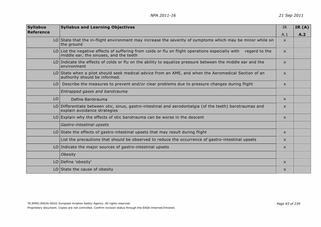
NPA 2011-16 21 Sep 2011
TE.RPRO.00034-002© European Aviation Safety Agency. All rights reserved.
Proprietary document. Copies are not controlled. Confirm revision status through the EASA-Internet/Intranet.
Page 83 of 239
Syllabus
Reference
Syllabus and Learning Objectives IR
A.1
IR (A)
A.2
LO State that the in-flight environment may increase the severity of symptoms which may be minor while on the ground
x
LO List the negative effects of suffering from colds or flu on flight operations especially with regard to the middle ear, the sinuses, and the teeth
x
LO Indicate the effects of colds or flu on the ability to equalize pressure between the middle ear and the environment
x
LO State when a pilot should seek medical advice from an AME, and when the Aeromedical Section of an authority should be informed.
x
LO Describe the measures to prevent and/or clear problems due to pressure changes during flight x
Entrapped gases and barotrauma
LO Define Barotrauma x
LO Differentiate between otic, sinus, gastro-intestinal and aerodontalgia (of the teeth) barotraumas and explain avoidance strategies
x
LO Explain why the effects of otic barotrauma can be worse in the descent x
Gastro-intestinal upsets
LO State the effects of gastro-intestinal upsets that may result during flight x
List the precautions that should be observed to reduce the occurrence of gastro-intestinal upsets x
LO Indicate the major sources of gastro-intestinal upsets x
Obesity
LO Define 'obesity' x
LO State the cause of obesity x
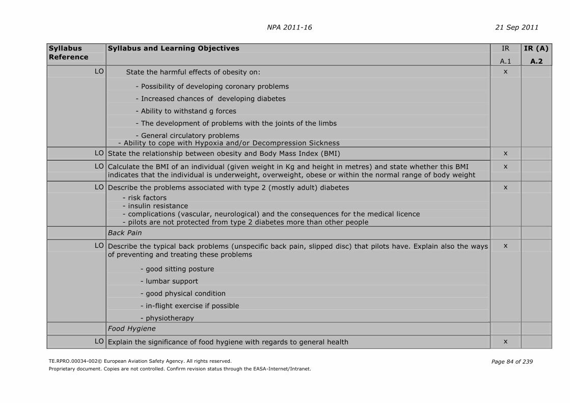
NPA 2011-16 21 Sep 2011
TE.RPRO.00034-002© European Aviation Safety Agency. All rights reserved.
Proprietary document. Copies are not controlled. Confirm revision status through the EASA-Internet/Intranet.
Page 84 of 239
Syllabus
Reference
Syllabus and Learning Objectives IR
A.1
IR (A)
A.2
LO State the harmful effects of obesity on:
- Possibility of developing coronary problems
- Increased chances of developing diabetes
- Ability to withstand g forces
- The development of problems with the joints of the limbs
- General circulatory problems - Ability to cope with Hypoxia and/or Decompression Sickness
x
LO State the relationship between obesity and Body Mass Index (BMI) x
LO Calculate the BMI of an individual (given weight in Kg and height in metres) and state whether this BMI indicates that the individual is underweight, overweight, obese or within the normal range of body weight
x
LO Describe the problems associated with type 2 (mostly adult) diabetes
- risk factors - insulin resistance - complications (vascular, neurological) and the consequences for the medical licence - pilots are not protected from type 2 diabetes more than other people
x
Back Pain
LO Describe the typical back problems (unspecific back pain, slipped disc) that pilots have. Explain also the ways
of preventing and treating these problems
- good sitting posture
- lumbar support
- good physical condition
- in-flight exercise if possible
- physiotherapy
x
Food Hygiene
LO Explain the significance of food hygiene with regards to general health x

NPA 2011-16 21 Sep 2011
TE.RPRO.00034-002© European Aviation Safety Agency. All rights reserved.
Proprietary document. Copies are not controlled. Confirm revision status through the EASA-Internet/Intranet.
Page 85 of 239
Syllabus
Reference
Syllabus and Learning Objectives IR
A.1
IR (A)
A.2
LO Stress the importance of and methods to be adopted by aircrew especially when travelling abroad to avoid
contaminated food and liquids
x
LO List the major contaminating sources in foodstuffs x
LO State the major constituents of a healthy diet x
LO State the measure to avoid hypoglycaemia x
LO State the role vitamins and trace elements are playing in a healthy diet x
LO State the importance of adequate hydration x
Infectious diseases
LO State the major infectious diseases that may kill or severely incapacitate individuals x
LO State which preventative hygienic measures, vaccinations, drugs, and other measures, reduce the chances of catching these diseases
x
LO State the precautions which must be taken to ensure that disease carrying insects are not transported between areas
x
040 02 03 04 Intoxication
Tobacco
LO State the harmful effects of tobacco on:
- The respiratory system - The cardio-vascular system - The ability to resist hypoxia - The ability to tolerate g forces - Night vision
x
Caffeine
LO Indicate the level of caffeine dosage at which performance is degraded x
LO Besides coffee, indicate other beverages containing caffeine x
Alcohol
LO State the maximum acceptable limit of alcohol for flight crew x
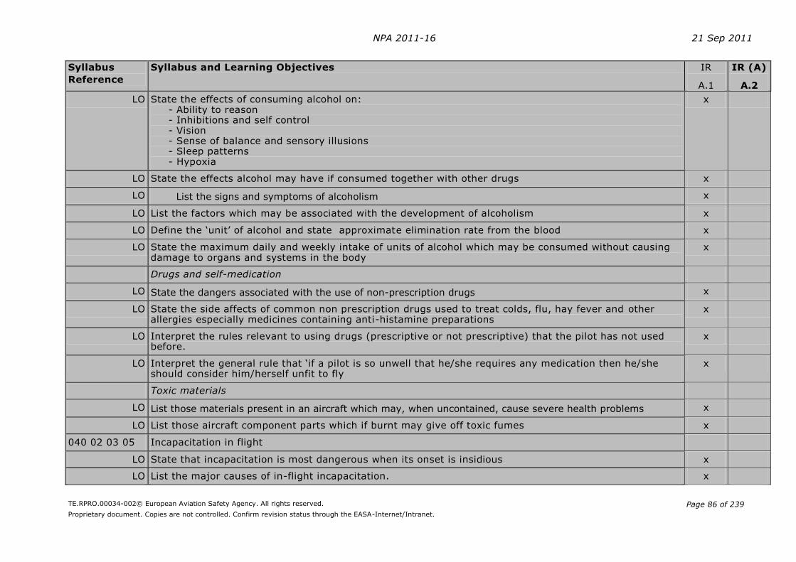
NPA 2011-16 21 Sep 2011
TE.RPRO.00034-002© European Aviation Safety Agency. All rights reserved.
Proprietary document. Copies are not controlled. Confirm revision status through the EASA-Internet/Intranet.
Page 86 of 239
Syllabus
Reference
Syllabus and Learning Objectives IR
A.1
IR (A)
A.2
LO State the effects of consuming alcohol on: - Ability to reason - Inhibitions and self control - Vision - Sense of balance and sensory illusions - Sleep patterns - Hypoxia
x
LO State the effects alcohol may have if consumed together with other drugs x
LO List the signs and symptoms of alcoholism x
LO List the factors which may be associated with the development of alcoholism x
LO Define the ‘unit’ of alcohol and state approximate elimination rate from the blood x
LO State the maximum daily and weekly intake of units of alcohol which may be consumed without causing damage to organs and systems in the body
x
Drugs and self-medication
LO State the dangers associated with the use of non-prescription drugs x
LO State the side affects of common non prescription drugs used to treat colds, flu, hay fever and other allergies especially medicines containing anti-histamine preparations
x
LO Interpret the rules relevant to using drugs (prescriptive or not prescriptive) that the pilot has not used before.
x
LO Interpret the general rule that ‘if a pilot is so unwell that he/she requires any medication then he/she should consider him/herself unfit to fly
x
Toxic materials
LO List those materials present in an aircraft which may, when uncontained, cause severe health problems x
LO List those aircraft component parts which if burnt may give off toxic fumes x
040 02 03 05 Incapacitation in flight
LO State that incapacitation is most dangerous when its onset is insidious x
LO List the major causes of in-flight incapacitation. x
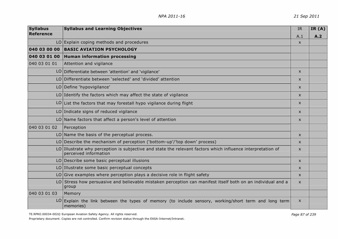
NPA 2011-16 21 Sep 2011
TE.RPRO.00034-002© European Aviation Safety Agency. All rights reserved.
Proprietary document. Copies are not controlled. Confirm revision status through the EASA-Internet/Intranet.
Page 87 of 239
Syllabus
Reference
Syllabus and Learning Objectives IR
A.1
IR (A)
A.2
LO Explain coping methods and procedures x
040 03 00 00 BASIC AVIATION PSYCHOLOGY
040 03 01 00 Human information processing
040 03 01 01 Attention and vigilance
LO Differentiate between ‘attention’ and ‘vigilance’ x
LO Differentiate between ‘selected’ and ‘divided’ attention x
LO Define ‘hypovigilance’ x
LO Identify the factors which may affect the state of vigilance x
LO List the factors that may forestall hypo vigilance during flight x
LO Indicate signs of reduced vigilance x
LO Name factors that affect a person's level of attention x
040 03 01 02 Perception
LO Name the basis of the perceptual process. x
LO Describe the mechanism of perception (‘bottom-up’/’top down’ process) x
LO Illustrate why perception is subjective and state the relevant factors which influence interpretation of perceived information
x
LO Describe some basic perceptual illusions x
LO Illustrate some basic perceptual concepts x
LO Give examples where perception plays a decisive role in flight safety x
LO Stress how persuasive and believable mistaken perception can manifest itself both on an individual and a group
x
040 03 01 03 Memory
LO Explain the link between the types of memory (to include sensory, working/short term and long term
memories)
x
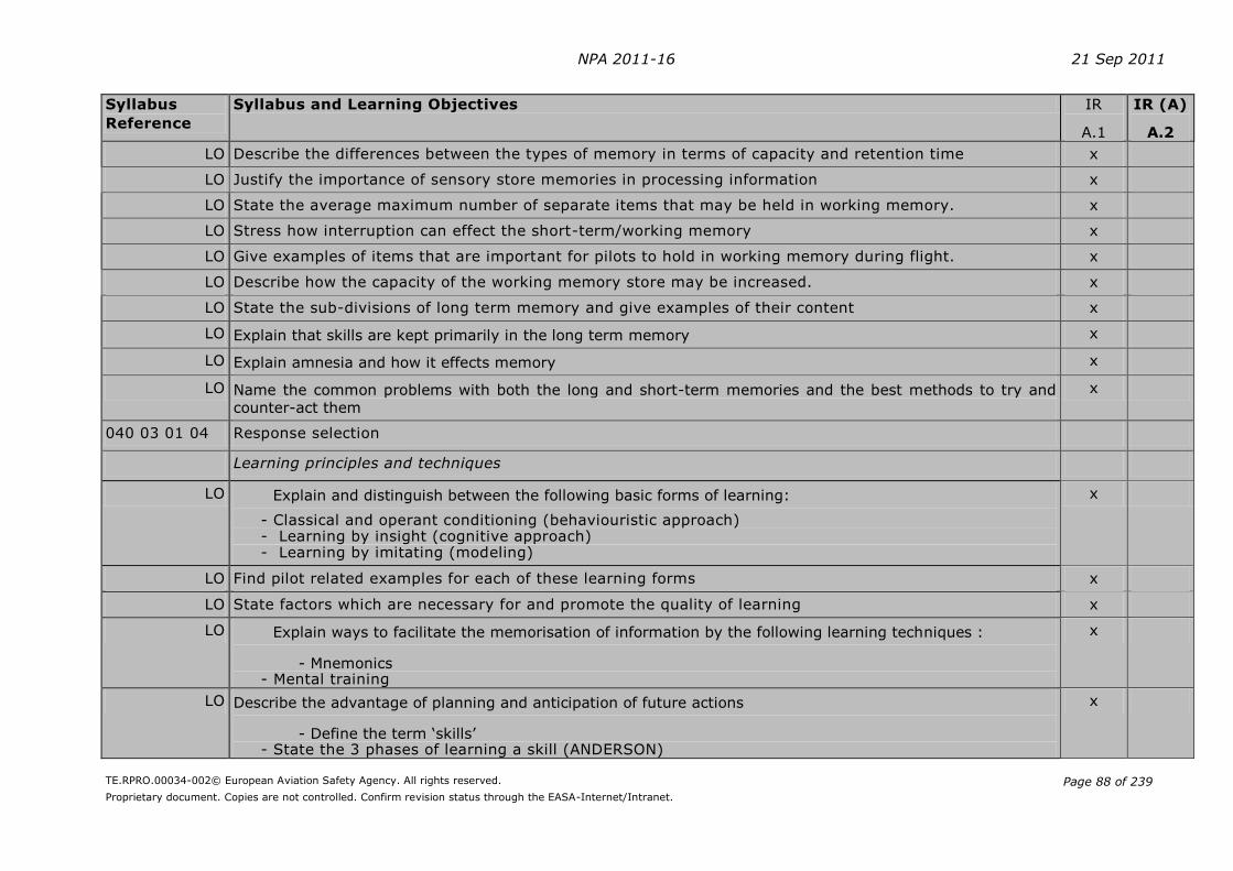
NPA 2011-16 21 Sep 2011
TE.RPRO.00034-002© European Aviation Safety Agency. All rights reserved.
Proprietary document. Copies are not controlled. Confirm revision status through the EASA-Internet/Intranet.
Page 88 of 239
Syllabus
Reference
Syllabus and Learning Objectives IR
A.1
IR (A)
A.2
LO Describe the differences between the types of memory in terms of capacity and retention time x
LO Justify the importance of sensory store memories in processing information x
LO State the average maximum number of separate items that may be held in working memory. x
LO Stress how interruption can effect the short-term/working memory x
LO Give examples of items that are important for pilots to hold in working memory during flight. x
LO Describe how the capacity of the working memory store may be increased. x
LO State the sub-divisions of long term memory and give examples of their content x
LO Explain that skills are kept primarily in the long term memory x
LO Explain amnesia and how it effects memory x
LO Name the common problems with both the long and short-term memories and the best methods to try and
counter-act them
x
040 03 01 04 Response selection
Learning principles and techniques
LO Explain and distinguish between the following basic forms of learning:
- Classical and operant conditioning (behaviouristic approach) - Learning by insight (cognitive approach) - Learning by imitating (modeling)
x
LO Find pilot related examples for each of these learning forms x
LO State factors which are necessary for and promote the quality of learning x
LO Explain ways to facilitate the memorisation of information by the following learning techniques :
- Mnemonics - Mental training
x
LO Describe the advantage of planning and anticipation of future actions
- Define the term ‘skills’ - State the 3 phases of learning a skill (ANDERSON)
x
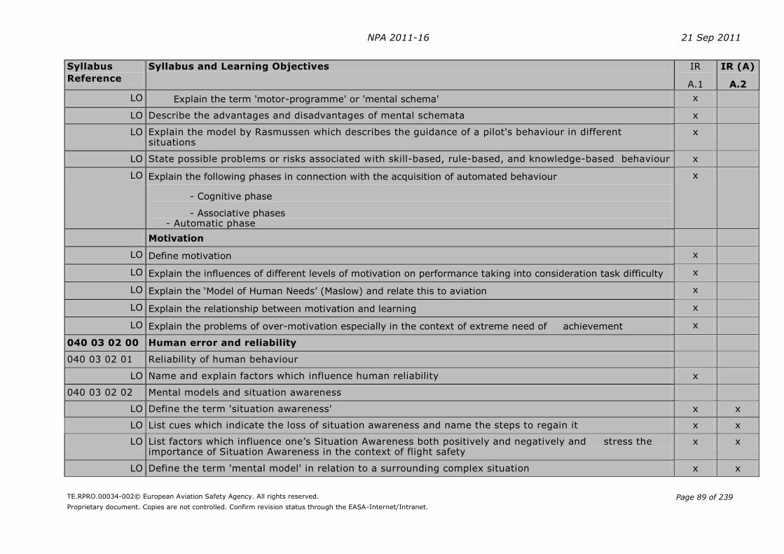
NPA 2011-16 21 Sep 2011
TE.RPRO.00034-002© European Aviation Safety Agency. All rights reserved.
Proprietary document. Copies are not controlled. Confirm revision status through the EASA-Internet/Intranet.
Page 89 of 239
Syllabus
Reference
Syllabus and Learning Objectives IR
A.1
IR (A)
A.2
LO Explain the term 'motor-programme' or 'mental schema' x
LO Describe the advantages and disadvantages of mental schemata x
LO Explain the model by Rasmussen which describes the guidance of a pilot's behaviour in different situations
x
LO State possible problems or risks associated with skill-based, rule-based, and knowledge-based behaviour x
LO Explain the following phases in connection with the acquisition of automated behaviour
- Cognitive phase
- Associative phases - Automatic phase
x
Motivation
LO Define motivation x
LO Explain the influences of different levels of motivation on performance taking into consideration task difficulty x
LO Explain the ‘Model of Human Needs’ (Maslow) and relate this to aviation x
LO Explain the relationship between motivation and learning x
LO Explain the problems of over-motivation especially in the context of extreme need of achievement x
040 03 02 00 Human error and reliability
040 03 02 01 Reliability of human behaviour
LO Name and explain factors which influence human reliability x
040 03 02 02 Mental models and situation awareness
LO Define the term 'situation awareness' x x
LO List cues which indicate the loss of situation awareness and name the steps to regain it x x
LO List factors which influence one’s Situation Awareness both positively and negatively and stress the importance of Situation Awareness in the context of flight safety
x x
LO Define the term 'mental model' in relation to a surrounding complex situation x x

NPA 2011-16 21 Sep 2011
TE.RPRO.00034-002© European Aviation Safety Agency. All rights reserved.
Proprietary document. Copies are not controlled. Confirm revision status through the EASA-Internet/Intranet.
Page 90 of 239
Syllabus
Reference
Syllabus and Learning Objectives IR
A.1
IR (A)
A.2
LO Describe the advantage/disadvantage of mental models x x
LO Explain the relationship between personal ‘mental models’ and the creation of cognitive illusions x x
040 03 02 03 Theory and model of human error
LO Define the term ‘error’ x x
LO Explain the concept of the ‘error chain’ x x
LO Differentiate between an isolated error and an error chain x x
LO Distinguish between the main forms/types of errors (i.e. slips, faults, omissions and violations) x x
LO Discuss the above errors and their relevance in-flight x x
LO Distinguish between an active and a latent error and give examples x x
040 03 02 04 Error generation
LO Distinguish between internal and external factors in error generation x x
LO Identify possible sources of internal error generation x x
LO Define and discuss the two errors associated with motor programmes x x
LO List the three main sources for external error generation in the cockpit x x
LO Give examples to illustrate the following factors in external error generation in the cockpit:
- Ergonomics
- Economics - Social environment
x x
LO Name major goals in the design of human centred man-machine interfaces x x
LO Define the term 'error tolerance' x x
LO List (and describe) strategies which are used to reduce human error x x
040 03 03 00 Decision making
040 03 03 01 Decision-making concepts

NPA 2011-16 21 Sep 2011
TE.RPRO.00034-002© European Aviation Safety Agency. All rights reserved.
Proprietary document. Copies are not controlled. Confirm revision status through the EASA-Internet/Intranet.
Page 91 of 239
Syllabus
Reference
Syllabus and Learning Objectives IR
A.1
IR (A)
A.2
LO Define the term 'deciding' and 'decision making' x x
LO Describe the major factors on which a decision-making should be based during the course of a flight x x
LO Describe the main human attributes with regard to decision making x x
LO Discuss the nature of bias and its influence on the decision making process x x
LO Describe the main error sources and limits in an individual's decision making mechanism x x
LO State the factors upon which an individual's risk assessment is based x x
LO Explain the relationship between risk assessment, commitment, and pressure of time on decision making strategies
x x
LO Describe the positive and negative influences exerted by other group members on an individual's decision
making process
x x
LO Explain the general idea behind the creation of a model for decision making based upon:
- definition of the aim
- collection of information
- risk assessment
- development of options
- evaluation of options - decision
- implementation
- consequences
- review and feedback
x x
040 03 04 00 Avoiding and managing errors: cockpit management
040 03 04 01 Safety awareness
LO Justify the need for being aware of not only one's own performance but that of others before and during a flight and the possible consequences and/or risks
x x
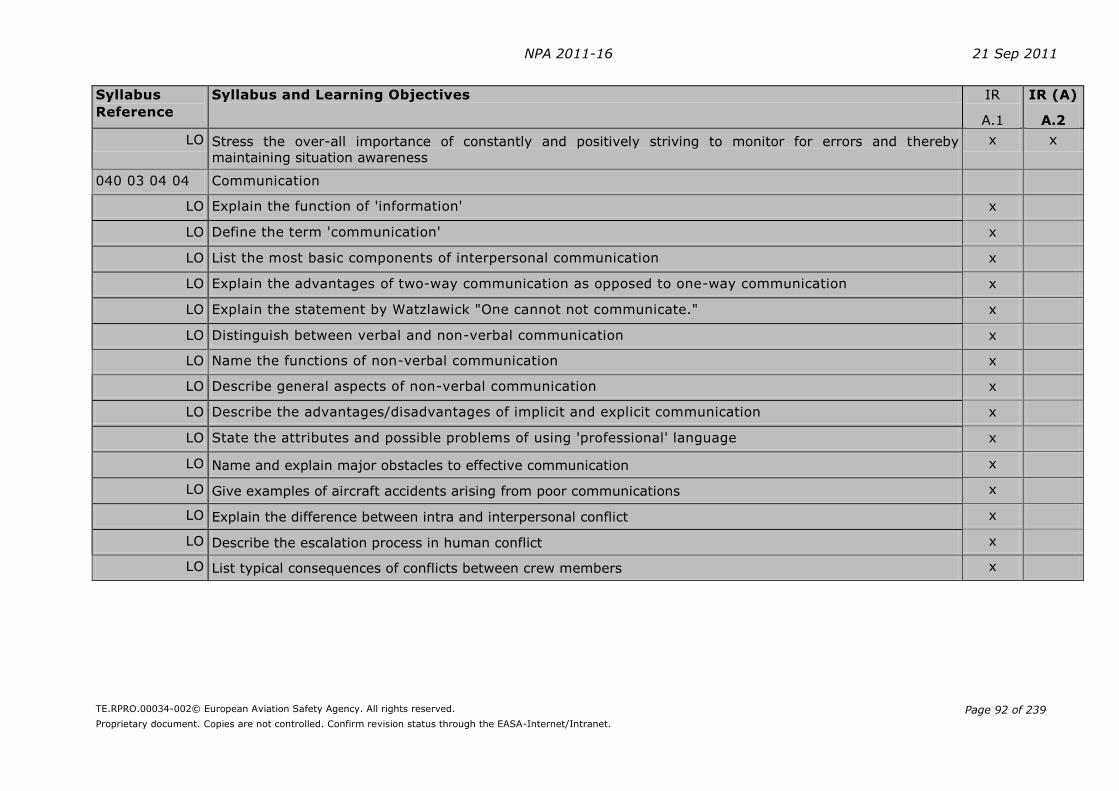
NPA 2011-16 21 Sep 2011
TE.RPRO.00034-002© European Aviation Safety Agency. All rights reserved.
Proprietary document. Copies are not controlled. Confirm revision status through the EASA-Internet/Intranet.
Page 92 of 239
Syllabus
Reference
Syllabus and Learning Objectives IR
A.1
IR (A)
A.2
LO Stress the over-all importance of constantly and positively striving to monitor for errors and thereby
maintaining situation awareness
x x
040 03 04 04 Communication
LO Explain the function of 'information' x
LO Define the term 'communication' x
LO List the most basic components of interpersonal communication x
LO Explain the advantages of two-way communication as opposed to one-way communication x
LO Explain the statement by Watzlawick "One cannot not communicate." x
LO Distinguish between verbal and non-verbal communication x
LO Name the functions of non-verbal communication x
LO Describe general aspects of non-verbal communication x
LO Describe the advantages/disadvantages of implicit and explicit communication x
LO State the attributes and possible problems of using 'professional' language x
LO Name and explain major obstacles to effective communication x
LO Give examples of aircraft accidents arising from poor communications x
LO Explain the difference between intra and interpersonal conflict x
LO Describe the escalation process in human conflict x
LO List typical consequences of conflicts between crew members x

NPA 2011-16 21 Sep 2011
TE.RPRO.00034-002© European Aviation Safety Agency. All rights reserved.
Proprietary document. Copies are not controlled. Confirm revision status through the EASA-Internet/Intranet.
Page 93 of 239
Syllabus
Reference
Syllabus and Learning Objectives IR
A.1
IR (A)
A.2
LO Explain the following terms as part of communication practice in regard to preventing or solving conflicts:
- Inquiry
- Active listening
- Advocacy
- Feedback
- Metacommunication
- Negotiation
x
040 03 05 00 Human behaviour
040 03 05 01 Personality, attitude and behaviour
LO Describe the factors which determine an individual's behaviour x
LO Define and distinguish between personality, attitude, and behaviour x
LO State the origin of personality and attitudes x
LO State that with behaviours good and bad habits can be formed x
LO Explain how behaviour is generally a product of personality and attitude x
LO Discuss some effects that personality and attitudes may have on flight crew performance x
040 03 05 02 Individual differences in personality and motivation
LO Describe the individual differences in personality by the mean of a common trait model (e.g.Eysenck's personality factors) and use it to describe today’s ideal pilot
x
Self-concept
LO Define the term 'self-concept' and the part it plays in any change of personality x
LO Explain how a self- concept of under-confidence may lead to an outward show of aggression and self- assertiveness
x

NPA 2011-16 21 Sep 2011
TE.RPRO.00034-002© European Aviation Safety Agency. All rights reserved.
Proprietary document. Copies are not controlled. Confirm revision status through the EASA-Internet/Intranet.
Page 94 of 239
Syllabus
Reference
Syllabus and Learning Objectives IR
A.1
IR (A)
A.2
Self-discipline
LO Define 'self-discipline' and justify its importance for flight safety x
040 03 06 00 Human overload and underload
040 03 06 01 Arousal
LO Explain the term 'arousal' x
LO Describe the relationship between arousal and performance x
LO Explain the circumstances under which underload may occur and its possible dangers x
040 03 06 02 Stress
LO Explain the term 'homeostasis' x
LO Explain the term 'stress'. Why is stress a natural human reaction x
LO State that the physiological response to stress is generated by the ‘fight or flight’ response x
LO Describe the function of the autonomic nervous system (ANS) in stress response x
LO Explain the biological reaction to stress by means of the general adaptation syndrome (GAS) x x
LO Explain the relationship between arousal and stress x
LO State the relationship between stress and performance x
LO State the basic categories of stressors x
LO List and discuss the major environmental sources of stress in the cockpit x
LO Discuss the concept of ‘break-point’ with regards to stress, overload and performance x
LO Name the principal causes of domestic stress x
LO State that the stress experienced as a result of particular demands varies between individuals x
LO Explain the factors which lead to differences in the levels of stress experienced by individuals x
LO List factors influencing the tolerance of stressors x
LO Explain a simple model of stress x

NPA 2011-16 21 Sep 2011
TE.RPRO.00034-002© European Aviation Safety Agency. All rights reserved.
Proprietary document. Copies are not controlled. Confirm revision status through the EASA-Internet/Intranet.
Page 95 of 239
Syllabus
Reference
Syllabus and Learning Objectives IR
A.1
IR (A)
A.2
LO Explain the relationship between stress and anxiety x
LO Describe the effects of anxiety on human performance x
LO State the general effect of acute stress on the human system x
LO Name the 3 phases of the GAS x x
LO Name the symptoms of stress relating to the different phases of the GAS x x
LO Describe the relationship between stress, arousal and vigilance x
LO State the general effect of chronic stress on the human system x
LO Explain the differences between psychological, psychosomatic and somatic stress reactions x
LO Name typical common physiological and psychological symptoms of human overload x
LO Describe effects of stress on human behaviour x
LO Explain how stress is cumulative and how stress from one situation can be transferred to a different situation x x
LO Explain how successful completion of a stressful task will reduce the amount of stress experienced when a
similar situation arises in the future
x x
LO Describe the effect of human under/overload on effectiveness in the cockpit x x
LO List sources and symptoms of human underload x x
040 03 06 05 Fatigue and stress management
LO Explain the term ‘fatigue’ and differentiate between the two types of fatigue x
LO Name causes for both types x
LO Identify symptoms and describe the effects of fatigue x
LO List strategies which prevent or delay the onset of fatigue and hypovigilance x
LO List and describe coping strategies for dealing with stress factors and stress reactions x
LO Distinguish between short-term and long-term methods of stress management x
LO Give examples of short term methods of stress management x

NPA 2011-16 21 Sep 2011
TE.RPRO.00034-002© European Aviation Safety Agency. All rights reserved.
Proprietary document. Copies are not controlled. Confirm revision status through the EASA-Internet/Intranet.
Page 96 of 239
Syllabus
Reference
Syllabus and Learning Objectives IR
A.1
IR (A)
A.2
LO Give examples of long-term methods of coping with stress x
040 03 07 00 Advanced cockpit automation
040 03 07 01 Advantages and disadvantages
LO Define and explain the basic concept of automation x x
LO List the advantages/disadvantages of automation in the cockpit in respect of level of vigilance, attention, workload, situation awareness and crew coordination
x x
LO State the advantages and disadvantages of the two components of the man-machine system with regard to information input and processing, decision making, and output activities
x x
LO Explain the ‘ironies of automation’ x x
LO Give examples of methods to overcome the disadvantages of automation x x
040 03 07 02 Automation complacency
LO State the main weaknesses in the monitoring of automatic systems x x
LO Explain the following terms in connection with automatic systems:
- Passive monitoring
- Blinkered concentration
- Confusion - Mode awareness
x x
LO Give examples of actions which may be taken to counteract ineffective monitoring of automatic systems x x
LO Define ‘complacency’ x x
040 03 07 03 Working concepts
LO Summarise how the negative effects of automation on pilots may be alleviated x x
LO Interpret the role of automation with respect to flight safety x x

NPA 2011-16 21 Sep 2011
TE.RPRO.00034-002© European Aviation Safety Agency. All rights reserved.
Proprietary document. Copies are not controlled. Confirm revision status through the EASA-Internet/Intranet.
Page 97 of 239
AMC5 FCL.615
DETAILED THEORETICAL KNOWLEDGE SYLLABUS AND LEARNING OBJECTIVES
Subject Meteorology (Competency-based modular course according to Appendix 6 A.2)
Syllabus reference
Syllabus details and associated Learning Objectives IR
A.1
IR (A)
A.2
050 00 00 00 METEOROLOGY
050 01 00 00 THE ATMOSPHERE
050 01 01 00 Composition, extent, vertical division
050 01 01 01 Structure of the atmosphere
LO Describe the vertical division of the atmosphere, based on the temperature variations with height x
LO List the different layers and their main qualitative characteristics x
050 01 01 02 Troposphere
LO Describe the troposphere x
LO Describe the main characteristics of the tropopause x
LO Describe the proportions of the most important gases in the air in the troposphere x
LO Describe the variations of the flight level and temperature of the tropopause from the poles to the equator
x
LO Describe the breaks in the tropopause along the boundaries of the main air masses x
LO Indicate the variations of the flight level of the tropopause with the seasons and the variations of atmospheric pressure
050 01 02 00 Air temperature
050 01 02 01 Definition and units
LO Define air temperature x
LO List the units of measurement of air temperature used in aviation meteorology (°C, °F, Kelvin) (Refer to 050 10 01 01)
x
050 01 02 02 Vertical distribution of temperature

NPA 2011-16 21 Sep 2011
TE.RPRO.00034-002© European Aviation Safety Agency. All rights reserved.
Proprietary document. Copies are not controlled. Confirm revision status through the EASA-Internet/Intranet.
Page 98 of 239
Syllabus reference
Syllabus details and associated Learning Objectives IR
A.1
IR (A)
A.2
LO Describe the mean vertical distribution of temperature up to 20 km x
LO Mention general causes of the cooling of the air in the troposphere with increasing altitude x
LO Calculate the temperature and temperature deviations at specified levels x
050 01 02 03 Transfer of heat
LO Explain how local cooling or warming processes result in transfer of heat x
LO Describe radiation x
LO Describe solar radiation reaching the earth x
LO Describe the filtering effect of the atmosphere on solar radiation x
LO Describe terrestrial radiation x
LO Explain how terrestrial radiation is absorbed by some components of the atmosphere x
LO Explain the greenhouse effect due to water vapour and some other gases in the atmosphere x
LO Explain the effect of absorption and radiation in connection with clouds x
LO Explain the process of conduction x
LO Explain the role of conduction in the cooling and warming of the atmosphere x
LO Explain the process of convection x
LO Name situations in which convection occurs x
LO Explain the process of advection x
LO Name situations in which advection occurs x
LO Describe transfer of heat by turbulence x
LO Describe transfer of latent heat x
050 01 02 04 Lapse rates
LO Describe qualitatively and quantitatively the temperature lapse rates of the troposphere (mean value 0.65°C/100 m or 2°C/1000 ft and actual values)
x x
050 01 02 05 Development of inversions, types of inversions
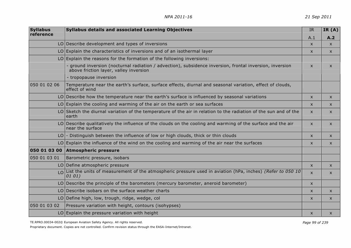
NPA 2011-16 21 Sep 2011
TE.RPRO.00034-002© European Aviation Safety Agency. All rights reserved.
Proprietary document. Copies are not controlled. Confirm revision status through the EASA-Internet/Intranet.
Page 99 of 239
Syllabus reference
Syllabus details and associated Learning Objectives IR
A.1
IR (A)
A.2
LO Describe development and types of inversions x x
LO Explain the characteristics of inversions and of an isothermal layer x x
LO Explain the reasons for the formation of the following inversions:
- ground inversion (nocturnal radiation / advection), subsidence inversion, frontal inversion, inversion above friction layer, valley inversion
x x
- tropopause inversion
050 01 02 06 Temperature near the earth’s surface, surface effects, diurnal and seasonal variation, effect of clouds, effect of wind
LO Describe how the temperature near the earth’s surface is influenced by seasonal variations x x
LO Explain the cooling and warming of the air on the earth or sea surfaces x x
LO Sketch the diurnal variation of the temperature of the air in relation to the radiation of the sun and of the earth
x x
LO Describe qualitatively the influence of the clouds on the cooling and warming of the surface and the air near the surface
x x
LO - Distinguish between the influence of low or high clouds, thick or thin clouds x x
LO Explain the influence of the wind on the cooling and warming of the air near the surfaces x x
050 01 03 00 Atmospheric pressure
050 01 03 01 Barometric pressure, isobars
LO Define atmospheric pressure x x
LO List the units of measurement of the atmospheric pressure used in aviation (hPa, inches) (Refer to 050 10 01 01)
x x
LO Describe the principle of the barometers (mercury barometer, aneroid barometer) x
LO Describe isobars on the surface weather charts x x
LO Define high, low, trough, ridge, wedge, col x x
050 01 03 02 Pressure variation with height, contours (isohypses)
LO Explain the pressure variation with height x x
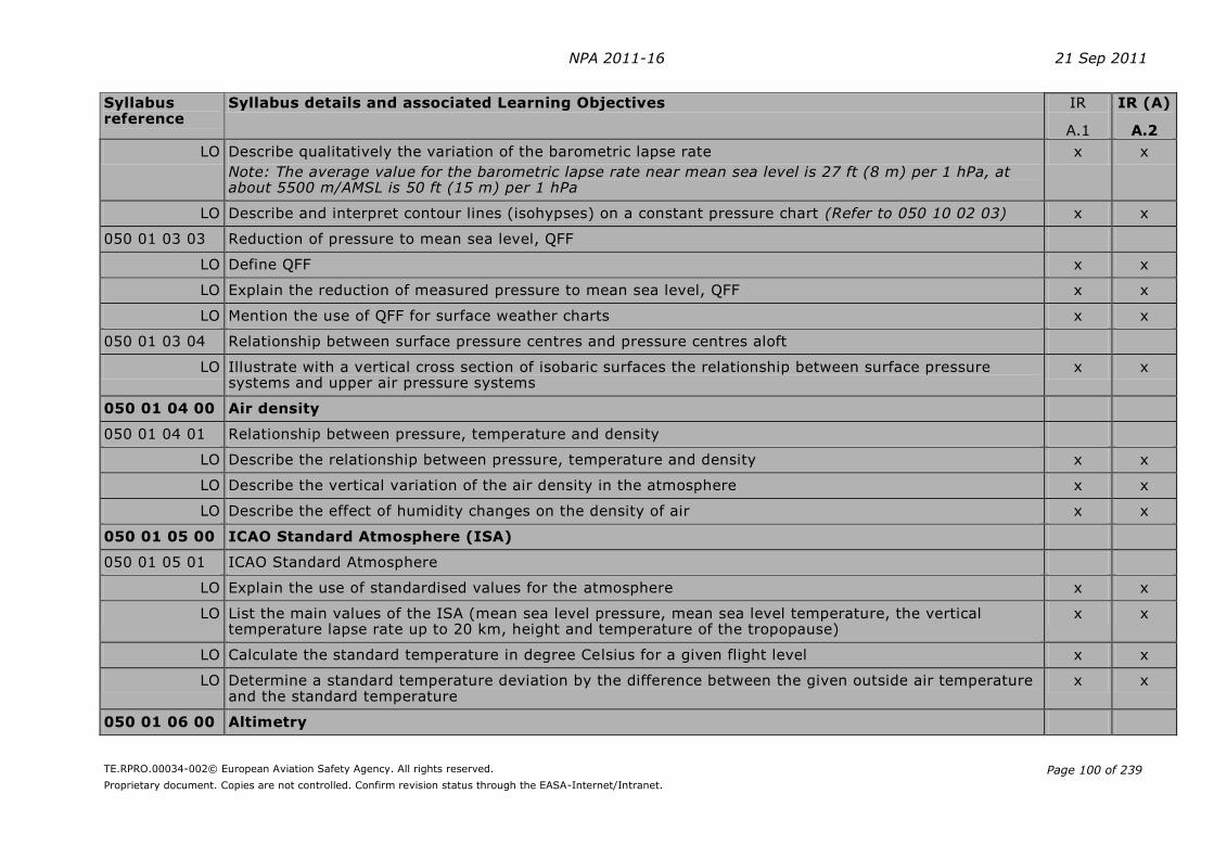
NPA 2011-16 21 Sep 2011
TE.RPRO.00034-002© European Aviation Safety Agency. All rights reserved.
Proprietary document. Copies are not controlled. Confirm revision status through the EASA-Internet/Intranet.
Page 100 of 239
Syllabus reference
Syllabus details and associated Learning Objectives IR
A.1
IR (A)
A.2
LO Describe qualitatively the variation of the barometric lapse rate
Note: The average value for the barometric lapse rate near mean sea level is 27 ft (8 m) per 1 hPa, at about 5500 m/AMSL is 50 ft (15 m) per 1 hPa
x x
LO Describe and interpret contour lines (isohypses) on a constant pressure chart (Refer to 050 10 02 03) x x
050 01 03 03 Reduction of pressure to mean sea level, QFF
LO Define QFF x x
LO Explain the reduction of measured pressure to mean sea level, QFF x x
LO Mention the use of QFF for surface weather charts x x
050 01 03 04 Relationship between surface pressure centres and pressure centres aloft
LO Illustrate with a vertical cross section of isobaric surfaces the relationship between surface pressure systems and upper air pressure systems
x x
050 01 04 00 Air density
050 01 04 01 Relationship between pressure, temperature and density
LO Describe the relationship between pressure, temperature and density x x
LO Describe the vertical variation of the air density in the atmosphere x x
LO Describe the effect of humidity changes on the density of air x x
050 01 05 00 ICAO Standard Atmosphere (ISA)
050 01 05 01 ICAO Standard Atmosphere
LO Explain the use of standardised values for the atmosphere x x
LO List the main values of the ISA (mean sea level pressure, mean sea level temperature, the vertical temperature lapse rate up to 20 km, height and temperature of the tropopause)
x x
LO Calculate the standard temperature in degree Celsius for a given flight level x x
LO Determine a standard temperature deviation by the difference between the given outside air temperature and the standard temperature
x x
050 01 06 00 Altimetry

NPA 2011-16 21 Sep 2011
TE.RPRO.00034-002© European Aviation Safety Agency. All rights reserved.
Proprietary document. Copies are not controlled. Confirm revision status through the EASA-Internet/Intranet.
Page 101 of 239
Syllabus reference
Syllabus details and associated Learning Objectives IR
A.1
IR (A)
A.2
050 01 06 01 Terminology and definitions
LO Define the following terms and abbreviations and explain how they are related to each other: height, altitude, pressure altitude, flight level, level, true altitude, true height, elevation, QNH, QFE and standard altimeter setting
x x
LO Describe the terms transition altitude, transition level, transition layer, terrain clearance, lowest usable flight level
x x
050 01 06 02 Altimeter settings
LO Name the altimeter settings associated to height, altitude, pressure altitude and flight level x
LO Describe the altimeter setting procedures x
050 01 06 03 Calculations
LO Calculate the different readings on the altimeter when the pilot changes the altimeter setting x x
LO Illustrate with a numbered example the changes of altimeter setting and the associated changes in reading when the pilot climbs through the transition altitude or descends through the transition level
x x
LO Derive the reading of the altimeter of an aircraft on the ground when the pilot uses the different settings x x
LO Explain the influence of the air temperature on the distance between the ground and the level read on the altimeter and between two flight levels
x x
LO Explain the influence of pressure areas on the true altitude x x
LO Determine the true altitude/height for a given altitude/height and a given ISA temperature deviation x x
LO Calculate the terrain clearance and the lowest usable flight level for given atmospheric temperature and pressure conditions
x x

NPA 2011-16 21 Sep 2011
TE.RPRO.00034-002© European Aviation Safety Agency. All rights reserved.
Proprietary document. Copies are not controlled. Confirm revision status through the EASA-Internet/Intranet.
Page 102 of 239
Syllabus reference
Syllabus details and associated Learning Objectives IR
A.1
IR (A)
A.2
Note: The following rules shall be considered for altimetry calculations:
a. All calculations are based on rounded pressure values to the nearest lower hPa
b. The value for the barometric lapse rate near mean sea level is 27 ft (8 m) per 1 hPa
c. To determine the true altitude/height the following rule of thumb, called the "4%-rule", shall be used: the altitude/height changes by 4% for each 10°C temperature deviation from ISA
d. If no further information is given, the deviation of outside air temperature from ISA is considered to be constantly the same given value in the whole layer
e. The elevation of the airport has to be taken into account. The temperature correction has to be considered for the layer between ground and the position of the aircraft
050 01 06 04 Effect of accelerated airflow due to topography
LO Describe qualitatively how the effect of accelerated airflow due to topography (Bernoulli effect) affects altimetry
x x
050 02 00 00 WIND
050 02 01 00 Definition and measurement of wind
050 02 01 01 Definition and measurement
LO Define wind x
LO State the units of wind direction and speed (kt, m/s, km/h) x
LO Explain how wind is measured in meteorology x
050 02 02 00 Primary cause of wind
050 02 02 01 Primary cause of wind, pressure gradient, coriolis force, gradient wind
LO Define the term horizontal pressure gradient x
LO Explain how the pressure gradient force acts in relation to the pressure gradient x
LO Explain how the coriolis force acts in relation to the wind x
LO Explain the development of the geostrophic wind x
LO Indicate how the geostrophic wind flows in relation to the isobars/isohypses in the northern and in the southern hemisphere
x
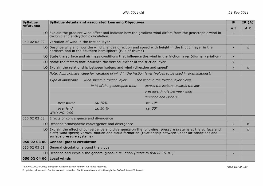
NPA 2011-16 21 Sep 2011
TE.RPRO.00034-002© European Aviation Safety Agency. All rights reserved.
Proprietary document. Copies are not controlled. Confirm revision status through the EASA-Internet/Intranet.
Page 103 of 239
Syllabus reference
Syllabus details and associated Learning Objectives IR
A.1
IR (A)
A.2
LO Explain the gradient wind effect and indicate how the gradient wind differs from the geostrophic wind in cyclonic and anticyclonic circulation
x
050 02 02 02 Variation of wind in the friction layer
LO Describe why and how the wind changes direction and speed with height in the friction layer in the northern and in the southern hemisphere (rule of thumb)
x x
LO State the surface and air mass conditions that influence the wind in the friction layer (diurnal variation) x
LO Name the factors that influence the vertical extent of the friction layer x
LO Explain the relationship between isobars and wind (direction and speed) x x
Note: Approximate value for variation of wind in the friction layer (values to be used in examinations):
Type of landscape Wind speed in friction layer The wind in the friction layer blows
in % of the geostrophic wind across the isobars towards the low
pressure. Angle between wind
direction and isobars
over water ca. 70% ca. 10°
over land ca. 50 % ca. 30°
WMO-NO. 266
050 02 02 03 Effects of convergence and divergence
LO Describe atmospheric convergence and divergence x x
LO Explain the effect of convergence and divergence on the following: pressure systems at the surface and aloft; wind speed; vertical motion and cloud formation (relationship between upper air conditions and surface pressure systems)
x x
050 02 03 00 General global circulation
050 02 03 01 General circulation around the globe
LO Describe and explain the general global circulation (Refer to 050 08 01 01) x
050 02 04 00 Local winds

NPA 2011-16 21 Sep 2011
TE.RPRO.00034-002© European Aviation Safety Agency. All rights reserved.
Proprietary document. Copies are not controlled. Confirm revision status through the EASA-Internet/Intranet.
Page 104 of 239
Syllabus reference
Syllabus details and associated Learning Objectives IR
A.1
IR (A)
A.2
050 02 04 01 Anabatic and katabatic winds, mountain and valley winds, venturi effects, land and sea breezes
LO Describe and explain anabatic and katabatic winds x x
LO Describe and explain mountain and valley winds x x
LO Describe and explain the venturi effect, convergence in valleys and mountain areas x x
LO Describe and explain land and sea breezes, sea breeze front x x
050 02 05 00 Mountain waves (standing waves, lee waves)
050 02 05 01 Origin and characteristics
LO Describe and explain the origin and formation of mountain waves x x
LO State the conditions necessary for the formation of mountain waves x x
LO Describe the structure and properties of mountain waves x x
LO Explain how mountain waves may be identified by their associated meteorological phenomena x x
050 02 06 00 Turbulence
050 02 06 01 Description and types of turbulence
LO Describe turbulence and gustiness x x
LO List common types of turbulence (convective, mechanical, orographic, frontal, clear air turbulence) x x
050 02 06 02 Formation and location of turbulence
LO Explain the formation of convective turbulence, mechanical and orographic turbulence, frontal turbulence, clear air turbulence (Refer to 050 02 06 03)
x x
LO State where turbulence will normally be found (rough ground surfaces, relief, inversion layers, CB, TS zones, unstable layers)
x x
050 02 06 03 Clear Air Turbulence (CAT): Description, cause and location
LO Describe the term CAT x
LO Explain the formation of CAT (Refer to 050 02 06 02) x
050 02 07 00 Jet streams

NPA 2011-16 21 Sep 2011
TE.RPRO.00034-002© European Aviation Safety Agency. All rights reserved.
Proprietary document. Copies are not controlled. Confirm revision status through the EASA-Internet/Intranet.
Page 105 of 239
Syllabus reference
Syllabus details and associated Learning Objectives IR
A.1
IR (A)
A.2
050 02 07 01 Description
LO Describe jet streams x
LO State the defined minimum speed of a jet stream x
LO State typical figures for the dimensions of jet streams x
050 03 00 00 THERMODYNAMICS
050 03 01 00 Humidity
050 03 01 01 Water vapour in the atmosphere
LO Describe humid air x x
LO Describe the significance for meteorology of water vapour in the atmosphere x x
LO Indicate the sources of atmospheric humidity x x
050 03 01 02 Mixing ratio
LO Define mixing ratio, saturation mixing ratio x
LO Name the unit used in meteorology to express the mixing ratio (g/kg) x
LO Explain the factors influencing the mixing ratio x
LO Recognise the lines of equal mixing ratio on a simplified diagram (T,P) x
LO Define saturation of air by water vapour x
LO Illustrate with a diagram (T, mixing ratio) the influence of the temperature on the saturation mixing ratio, at constant pressure
x
LO Explain the influence of the pressure on the saturation mixing ratio x
Note: A simplified diagram (T,P) contains
- on the x-axis temperature (T)
- on the y-axis height corresponding to pressure (P)
The degree of saturation/mixing ratio, stability/instability are shown as functions of temperature change with height (as lines or curves in the diagram)
050 03 01 03 Temperature/dew point, relative humidity

NPA 2011-16 21 Sep 2011
TE.RPRO.00034-002© European Aviation Safety Agency. All rights reserved.
Proprietary document. Copies are not controlled. Confirm revision status through the EASA-Internet/Intranet.
Page 106 of 239
Syllabus reference
Syllabus details and associated Learning Objectives IR
A.1
IR (A)
A.2
LO Define dew point x x
LO Recognise the dew point curve on a simplified diagram (T,P) x x
LO Define relative humidity x x
LO Explain the factors influencing the relative humidity at constant pressure x x
LO Explain the diurnal variation of the relative humidity x x
LO Describe the relationship between relative humidity, the amount of water vapour and the temperature x x
LO Describe the relationship between temperature and dew point x x
LO Estimate the relative humidity of the air from the difference between dew point and temperature x x
050 03 02 00 Change of state of aggregation
050 03 02 01 Condensation, evaporation, sublimation, freezing and melting, latent heat
LO Define condensation, evaporation, sublimation, freezing, melting and latent heat x
LO List the conditions for condensation / evaporation x
LO Explain the condensation process x
LO Explain the nature of and the need for condensation nuclei x
LO Explain the effects of condensation on the weather x
LO List the conditions for freezing / melting x
LO Explain the process of freezing x
LO Explain the nature of and the need for freezing nuclei x
LO Define supercooled water (Refer to 050 09 01 01) x
LO List the conditions for sublimation x
LO Explain the sublimation process x
LO Explain the nature of and the need for sublimation nuclei x
LO Describe the absorption or release of latent heat in each change of state of aggregation x
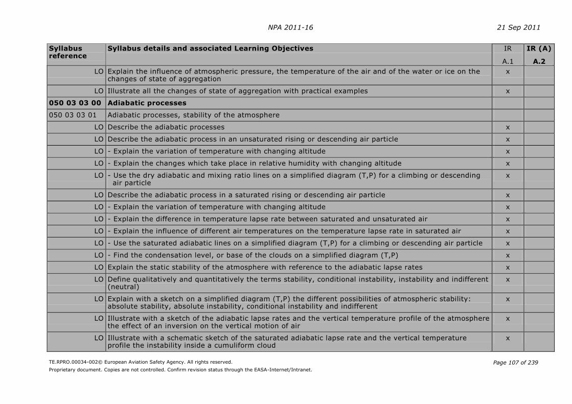
NPA 2011-16 21 Sep 2011
TE.RPRO.00034-002© European Aviation Safety Agency. All rights reserved.
Proprietary document. Copies are not controlled. Confirm revision status through the EASA-Internet/Intranet.
Page 107 of 239
Syllabus reference
Syllabus details and associated Learning Objectives IR
A.1
IR (A)
A.2
LO Explain the influence of atmospheric pressure, the temperature of the air and of the water or ice on the changes of state of aggregation
x
LO Illustrate all the changes of state of aggregation with practical examples x
050 03 03 00 Adiabatic processes
050 03 03 01 Adiabatic processes, stability of the atmosphere
LO Describe the adiabatic processes x
LO Describe the adiabatic process in an unsaturated rising or descending air particle x
LO - Explain the variation of temperature with changing altitude x
LO - Explain the changes which take place in relative humidity with changing altitude x
LO - Use the dry adiabatic and mixing ratio lines on a simplified diagram (T,P) for a climbing or descending air particle
x
LO Describe the adiabatic process in a saturated rising or descending air particle x
LO - Explain the variation of temperature with changing altitude x
LO - Explain the difference in temperature lapse rate between saturated and unsaturated air x
LO - Explain the influence of different air temperatures on the temperature lapse rate in saturated air x
LO - Use the saturated adiabatic lines on a simplified diagram (T,P) for a climbing or descending air particle x
LO - Find the condensation level, or base of the clouds on a simplified diagram (T,P) x
LO Explain the static stability of the atmosphere with reference to the adiabatic lapse rates x
LO Define qualitatively and quantitatively the terms stability, conditional instability, instability and indifferent (neutral)
x
LO Explain with a sketch on a simplified diagram (T,P) the different possibilities of atmospheric stability: absolute stability, absolute instability, conditional instability and indifferent
x
LO Illustrate with a sketch of the adiabatic lapse rates and the vertical temperature profile of the atmosphere the effect of an inversion on the vertical motion of air
x
LO Illustrate with a schematic sketch of the saturated adiabatic lapse rate and the vertical temperature profile the instability inside a cumuliform cloud
x

NPA 2011-16 21 Sep 2011
TE.RPRO.00034-002© European Aviation Safety Agency. All rights reserved.
Proprietary document. Copies are not controlled. Confirm revision status through the EASA-Internet/Intranet.
Page 108 of 239
Syllabus reference
Syllabus details and associated Learning Objectives IR
A.1
IR (A)
A.2
LO Illustrate with a schematic sketch the formation of the subsidence inversion x
LO Illustrate with a schematic sketch the formation of Foehn x
LO Explain the effect on the stability of the air caused by advection of air (warm or cold) x
Note: Dry adiabatic lapse rate = 1°C/100 m or 3°C/1000 ft; average value at lower levels for saturated adiabatic lapse rate = 0.6°C/100 m or 1.8°C/1000 ft (values to be used in examinations)
050 04 00 00 CLOUDS AND FOG
050 04 01 00 Cloud formation and description
050 04 01 01 Cloud formation
LO Explain cloud formation by adiabatic cooling, conduction, advection and radiation x x
LO Describe the cloud formation based on the following lifting processes: unorganised lifting in thin layers and turbulent mixing; forced lifting at fronts or over mountains; free convection
x x
LO Determine the cloud base and top in a simplified diagram (temperature, pressure, humidity) x x
LO Explain the influence of relative humidity on the height of the cloud base x x
LO Illustrate in a thermodynamic diagram the meaning of convective temperature (temperature at which formation of cumulus starts)
x x
LO List cloud types typical for stable and unstable air conditions x x
LO Summarise the conditions for the dissipation of clouds x x
050 04 01 02 Cloud types and cloud classification
LO Describe cloud types and cloud classification x x
LO Identify by shape cirriform, cumuliform and stratiform clouds x x
LO Identify by shape and typical level the ten cloud types (genera) x x
LO Describe and identify by shape the following species and supplementary feature: castellanus, lenticularis, fractus, humilis, mediocris, congestus, calvus, capillatus and virga
x x
LO Distinguish between low, medium and high level clouds according to the WMO cloud étage (including heights)
- for mid-latitudes x x
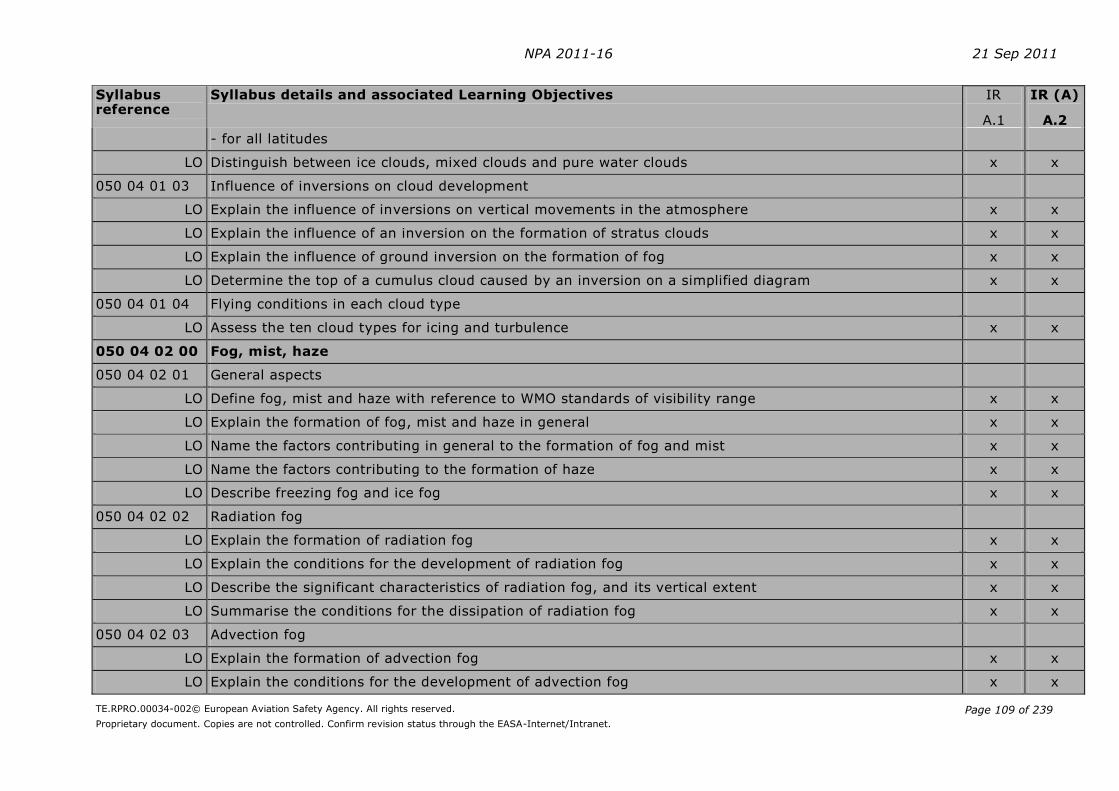
NPA 2011-16 21 Sep 2011
TE.RPRO.00034-002© European Aviation Safety Agency. All rights reserved.
Proprietary document. Copies are not controlled. Confirm revision status through the EASA-Internet/Intranet.
Page 109 of 239
Syllabus reference
Syllabus details and associated Learning Objectives IR
A.1
IR (A)
A.2
- for all latitudes
LO Distinguish between ice clouds, mixed clouds and pure water clouds x x
050 04 01 03 Influence of inversions on cloud development
LO Explain the influence of inversions on vertical movements in the atmosphere x x
LO Explain the influence of an inversion on the formation of stratus clouds x x
LO Explain the influence of ground inversion on the formation of fog x x
LO Determine the top of a cumulus cloud caused by an inversion on a simplified diagram x x
050 04 01 04 Flying conditions in each cloud type
LO Assess the ten cloud types for icing and turbulence x x
050 04 02 00 Fog, mist, haze
050 04 02 01 General aspects
LO Define fog, mist and haze with reference to WMO standards of visibility range x x
LO Explain the formation of fog, mist and haze in general x x
LO Name the factors contributing in general to the formation of fog and mist x x
LO Name the factors contributing to the formation of haze x x
LO Describe freezing fog and ice fog x x
050 04 02 02 Radiation fog
LO Explain the formation of radiation fog x x
LO Explain the conditions for the development of radiation fog x x
LO Describe the significant characteristics of radiation fog, and its vertical extent x x
LO Summarise the conditions for the dissipation of radiation fog x x
050 04 02 03 Advection fog
LO Explain the formation of advection fog x x
LO Explain the conditions for the development of advection fog x x

NPA 2011-16 21 Sep 2011
TE.RPRO.00034-002© European Aviation Safety Agency. All rights reserved.
Proprietary document. Copies are not controlled. Confirm revision status through the EASA-Internet/Intranet.
Page 110 of 239
Syllabus reference
Syllabus details and associated Learning Objectives IR
A.1
IR (A)
A.2
LO Describe the different possibilities of advection fog formation (over land, sea and coastal regions) x x
LO Describe significant characteristics of advection fog x x
LO Summarise the conditions for the dissipation of advection fog x x
050 04 02 04 Steam fog
LO Explain the formation of steam fog x x
LO Explain the conditions for the development of steam fog x x
LO Describe significant characteristics of steam fog x x
LO Summarise the conditions for the dissipation of steam fog x x
050 04 02 05 Frontal fog
LO Explain the formation of frontal fog x x
LO Explain the conditions for the development of frontal fog x x
LO Describe significant characteristics of frontal fog x x
LO Summarise the conditions for the dissipation of frontal fog x x
050 04 02 06 Orographic fog (hill fog)
LO Summarise the features of orographic fog x x
LO Explain the conditions for the development of orographic fog x x
LO Describe significant characteristics of orographic fog x x
LO Summarise the conditions for the dissipation of orographic fog x x
050 05 00 00 PRECIPITATION
050 05 01 00 Development of precipitation
050 05 01 01 Process of development of precipitation
LO Distinguish between the two following processes by which precipitation is formed x x
LO - Summarise the outlines of the ice crystal process (Bergeron-Findeisen) x x
LO - Summarise the outlines of the coalescence process x x
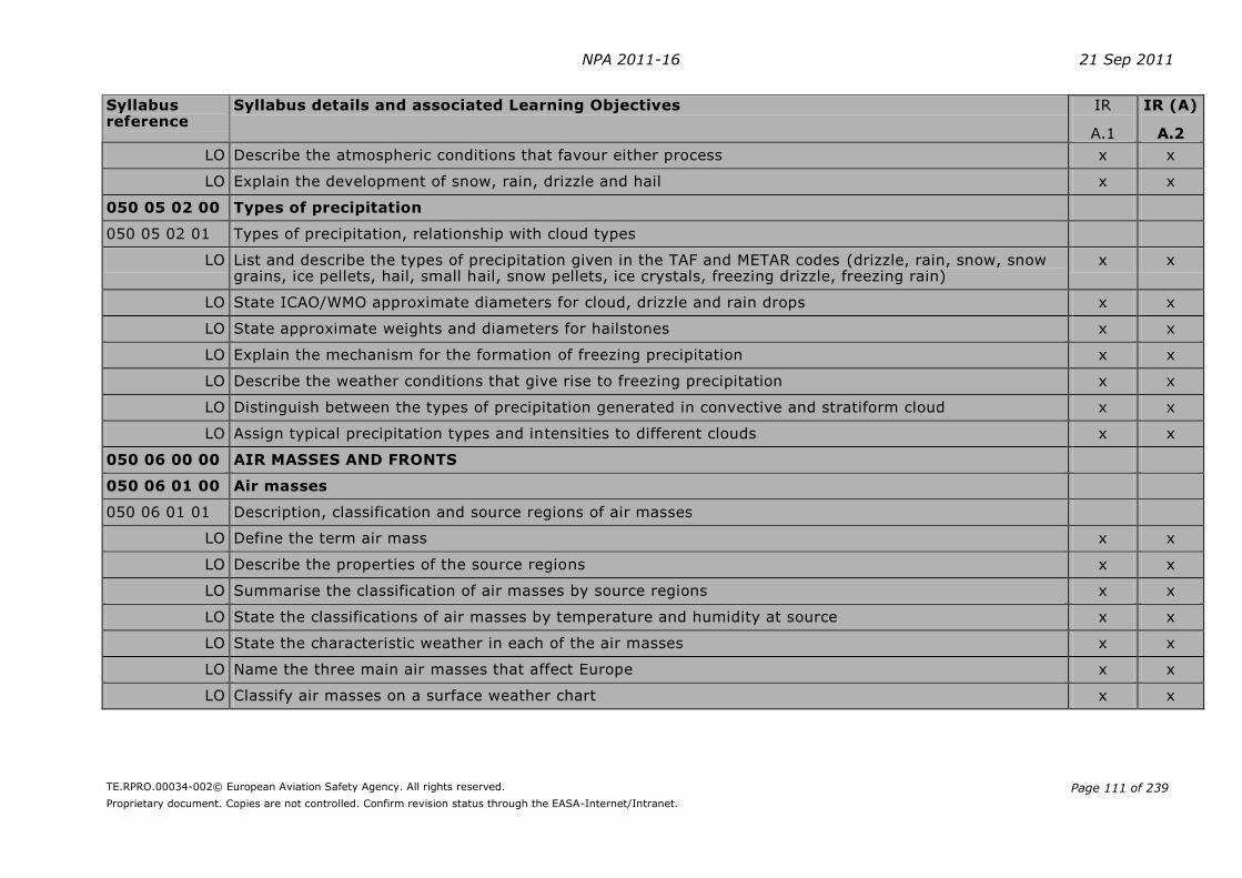
NPA 2011-16 21 Sep 2011
TE.RPRO.00034-002© European Aviation Safety Agency. All rights reserved.
Proprietary document. Copies are not controlled. Confirm revision status through the EASA-Internet/Intranet.
Page 111 of 239
Syllabus reference
Syllabus details and associated Learning Objectives IR
A.1
IR (A)
A.2
LO Describe the atmospheric conditions that favour either process x x
LO Explain the development of snow, rain, drizzle and hail x x
050 05 02 00 Types of precipitation
050 05 02 01 Types of precipitation, relationship with cloud types
LO List and describe the types of precipitation given in the TAF and METAR codes (drizzle, rain, snow, snow grains, ice pellets, hail, small hail, snow pellets, ice crystals, freezing drizzle, freezing rain)
x x
LO State ICAO/WMO approximate diameters for cloud, drizzle and rain drops x x
LO State approximate weights and diameters for hailstones x x
LO Explain the mechanism for the formation of freezing precipitation x x
LO Describe the weather conditions that give rise to freezing precipitation x x
LO Distinguish between the types of precipitation generated in convective and stratiform cloud x x
LO Assign typical precipitation types and intensities to different clouds x x
050 06 00 00 AIR MASSES AND FRONTS
050 06 01 00 Air masses
050 06 01 01 Description, classification and source regions of air masses
LO Define the term air mass x x
LO Describe the properties of the source regions x x
LO Summarise the classification of air masses by source regions x x
LO State the classifications of air masses by temperature and humidity at source x x
LO State the characteristic weather in each of the air masses x x
LO Name the three main air masses that affect Europe x x
LO Classify air masses on a surface weather chart x x

NPA 2011-16 21 Sep 2011
TE.RPRO.00034-002© European Aviation Safety Agency. All rights reserved.
Proprietary document. Copies are not controlled. Confirm revision status through the EASA-Internet/Intranet.
Page 112 of 239
Syllabus reference
Syllabus details and associated Learning Objectives IR
A.1
IR (A)
A.2
Note: Names and abbreviations of air masses used in examinations:
- first letter: humidity continental (c), maritime (m)
- second letter: type of air mass Arctic (A), Polar (P), Tropical (T), Equatorial (E)
- third letter: temperature cold (c), warm (w)
050 06 01 02 Modifications of air masses
LO List the environmental factors that affect the final properties of an air mass x x
LO Explain how maritime and continental tracks modify air masses x x
LO Explain the effect of passage over cold or warm surfaces x x
LO Explain how air mass weather is affected by the season, the air mass track and by orographic and thermal effects over land
x x
LO Assess the tendencies of the stability for an air mass and describe the typical resulting air mass weather including the hazards for aviation
x x
050 06 02 00 Fronts
050 06 02 01 General aspects
LO Describe the boundaries between air masses (fronts) x x
LO Define front and frontal surface (frontal zone) x x
LO Name the global frontal systems (polar front, arctic front) x
LO State the approximate seasonal latitudes and geographic positions of the polar front and the arctic front x
050 06 02 02 Warm front, associated clouds and weather
LO Define a warm front x x
LO Describe the cloud, weather, ground visibility and aviation hazards at a warm front depending on the stability of the warm air
x x
LO Explain the seasonal differences in the weather at warm fronts x x
LO Describe the structure, slope and dimensions of a warm front x x
LO Sketch a cross-section of a warm front, showing weather, cloud and aviation hazards x x

NPA 2011-16 21 Sep 2011
TE.RPRO.00034-002© European Aviation Safety Agency. All rights reserved.
Proprietary document. Copies are not controlled. Confirm revision status through the EASA-Internet/Intranet.
Page 113 of 239
Syllabus reference
Syllabus details and associated Learning Objectives IR
A.1
IR (A)
A.2
050 06 02 03 Cold front, associated clouds and weather
LO Define a cold front x x
LO Describe the cloud, weather, ground visibility and aviation hazards at a cold front depending on the stability of the warm air
x x
LO Explain the seasonal differences in the weather at cold fronts x x
LO Describe the structure, slope and dimensions of a cold front x x
LO Sketch a cross-section of a cold front, showing weather, cloud and aviation hazards x x
050 06 02 04 Warm sector, associated clouds and weather
LO Define fronts and air masses associated with the warm sector x x
LO Describe the cloud, weather, ground visibility and aviation hazards in a warm sector x x
LO Explain the seasonal differences in the weather in the warm sector x x
LO Sketch a cross-section of a warm sector, showing weather, cloud and aviation hazards x x
050 06 02 05 Weather behind the cold front
LO Describe the cloud, weather, ground visibility and aviation hazards behind the cold front x x
LO Explain the seasonal differences in the weather behind the cold front x x
050 06 02 06 Occlusions, associated clouds and weather
LO Define the term occlusion x x
LO Define a cold occlusion x x
LO Define a warm occlusion x x
LO Describe the cloud, weather, ground visibility and aviation hazards in a cold occlusion x x
LO Describe the cloud, weather, ground visibility and aviation hazards in a warm occlusion x x
LO Explain the seasonal differences in the weather at occlusions x x
LO Sketch a cross-section of cold and warm occlusions, showing weather, cloud and aviation hazards x x
LO In a sketch plan illustrate the development of an occlusion and the movement of the occlusion point x x
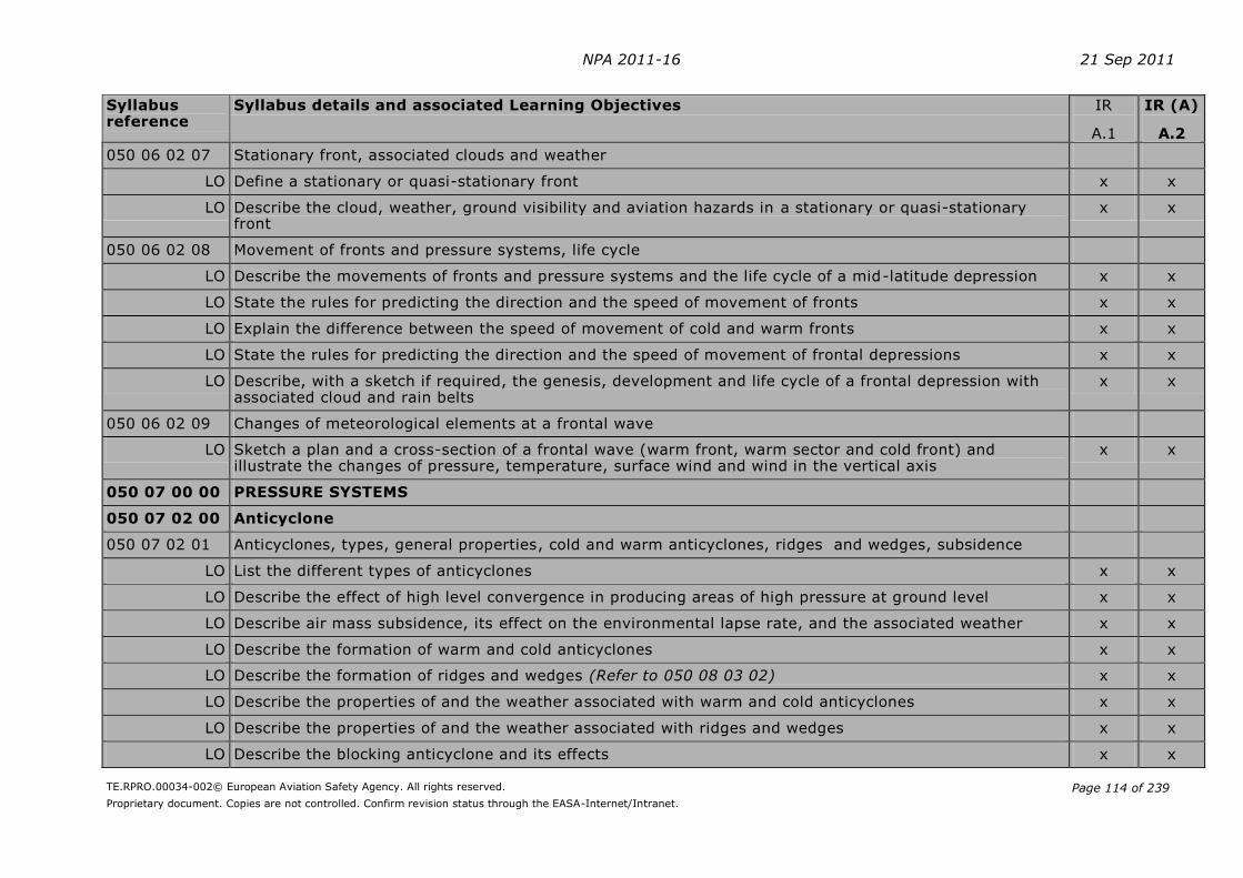
NPA 2011-16 21 Sep 2011
TE.RPRO.00034-002© European Aviation Safety Agency. All rights reserved.
Proprietary document. Copies are not controlled. Confirm revision status through the EASA-Internet/Intranet.
Page 114 of 239
Syllabus reference
Syllabus details and associated Learning Objectives IR
A.1
IR (A)
A.2
050 06 02 07 Stationary front, associated clouds and weather
LO Define a stationary or quasi-stationary front x x
LO Describe the cloud, weather, ground visibility and aviation hazards in a stationary or quasi-stationary front
x x
050 06 02 08 Movement of fronts and pressure systems, life cycle
LO Describe the movements of fronts and pressure systems and the life cycle of a mid-latitude depression x x
LO State the rules for predicting the direction and the speed of movement of fronts x x
LO Explain the difference between the speed of movement of cold and warm fronts x x
LO State the rules for predicting the direction and the speed of movement of frontal depressions x x
LO Describe, with a sketch if required, the genesis, development and life cycle of a frontal depression with associated cloud and rain belts
x x
050 06 02 09 Changes of meteorological elements at a frontal wave
LO Sketch a plan and a cross-section of a frontal wave (warm front, warm sector and cold front) and illustrate the changes of pressure, temperature, surface wind and wind in the vertical axis
x x
050 07 00 00 PRESSURE SYSTEMS
050 07 02 00 Anticyclone
050 07 02 01 Anticyclones, types, general properties, cold and warm anticyclones, ridges and wedges, subsidence
LO List the different types of anticyclones x x
LO Describe the effect of high level convergence in producing areas of high pressure at ground level x x
LO Describe air mass subsidence, its effect on the environmental lapse rate, and the associated weather x x
LO Describe the formation of warm and cold anticyclones x x
LO Describe the formation of ridges and wedges (Refer to 050 08 03 02) x x
LO Describe the properties of and the weather associated with warm and cold anticyclones x x
LO Describe the properties of and the weather associated with ridges and wedges x x
LO Describe the blocking anticyclone and its effects x x

NPA 2011-16 21 Sep 2011
TE.RPRO.00034-002© European Aviation Safety Agency. All rights reserved.
Proprietary document. Copies are not controlled. Confirm revision status through the EASA-Internet/Intranet.
Page 115 of 239
Syllabus reference
Syllabus details and associated Learning Objectives IR
A.1
IR (A)
A.2
050 07 03 00 Non frontal depressions
050 07 03 01 Thermal-, orographic-, polar- and secondary depressions, troughs
LO Describe the effect of high level divergence in producing areas of low pressure at ground level x x
LO Describe the formation and properties of thermal-, orographic- (lee lows), polar- and secondary depressions
x x
LO Describe the formation, the properties and the associated weather of troughs x x
050 08 00 00 CLIMATOLOGY
050 08 03 00 Typical weather situations in the mid-latitudes
050 08 03 01 Westerly situation (westerlies)
LO Identify on a weather chart the typical westerly situation with travelling polar front waves x x
LO Describe the typical weather in the region of the travelling polar front waves including the seasonal variations
x x
LO State the differences between the northern and the southern hemisphere (roaring forties)
050 08 03 02 High pressure area
LO Describe the high pressure zones with the associated weather x x
LO Identify on a weather chart high pressure regions x x
LO Describe the weather associated with wedges in the polar air (Refer to 050 07 02 01) x x
050 08 03 03 Flat pressure pattern
LO Identify on a surface weather chart the typical flat pressure pattern x x
LO Describe the weather associated with a flat pressure pattern x x
050 08 03 04 Cold air pool (cold air drop)
LO Define cold air pool x
LO Describe the formation of a cold air pool x
LO Describe the characteristics of a cold air pool with regard to dimensions, duration of life, geographical position, seasons, movements, weather activities and dissipation
x
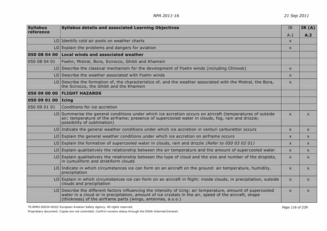
NPA 2011-16 21 Sep 2011
TE.RPRO.00034-002© European Aviation Safety Agency. All rights reserved.
Proprietary document. Copies are not controlled. Confirm revision status through the EASA-Internet/Intranet.
Page 116 of 239
Syllabus reference
Syllabus details and associated Learning Objectives IR
A.1
IR (A)
A.2
LO Identify cold air pools on weather charts x
LO Explain the problems and dangers for aviation x
050 08 04 00 Local winds and associated weather
050 08 04 01 Foehn, Mistral, Bora, Scirocco, Ghibli and Khamsin
LO Describe the classical mechanism for the development of Foehn winds (including Chinook) x
LO Describe the weather associated with Foehn winds x
LO Describe the formation of, the characteristics of, and the weather associated with the Mistral, the Bora, the Scirocco, the Ghibli and the Khamsin
x
050 09 00 00 FLIGHT HAZARDS
050 09 01 00 Icing
050 09 01 01 Conditions for ice accretion
LO Summarise the general conditions under which ice accretion occurs on aircraft (temperatures of outside air; temperature of the airframe; presence of supercooled water in clouds, fog, rain and drizzle; possibility of sublimation)
x x
LO Indicate the general weather conditions under which ice accretion in venturi carburettor occurs x x
LO Explain the general weather conditions under which ice accretion on airframe occurs x x
LO Explain the formation of supercooled water in clouds, rain and drizzle (Refer to 050 03 02 01) x x
LO Explain qualitatively the relationship between the air temperature and the amount of supercooled water x x
LO Explain qualitatively the relationship between the type of cloud and the size and number of the droplets, in cumuliform and stratiform clouds
x x
LO Indicate in which circumstances ice can form on an aircraft on the ground: air temperature, humidity, precipitation
x x
LO Explain in which circumstances ice can form on an aircraft in flight: inside clouds, in precipitation, outside clouds and precipitation
x x
LO Describe the different factors influencing the intensity of icing: air temperature, amount of supercooled water in a cloud or in precipitation, amount of ice crystals in the air, speed of the aircraft, shape (thickness) of the airframe parts (wings, antennas, a.s.o.)
x x

NPA 2011-16 21 Sep 2011
TE.RPRO.00034-002© European Aviation Safety Agency. All rights reserved.
Proprietary document. Copies are not controlled. Confirm revision status through the EASA-Internet/Intranet.
Page 117 of 239
Syllabus reference
Syllabus details and associated Learning Objectives IR
A.1
IR (A)
A.2
LO Explain the effects of topography on icing x x
LO Explain the higher concentration of water drops in stratiform orographic clouds x x
050 09 01 02 Types of ice accretion
LO Define clear ice x x
LO Describe the conditions for the formation of clear ice x x
LO Explain the formation of the structure of clear ice with the release of latent heat during the freezing process
x x
LO Describe the aspect of clear ice: appearance, weight, solidity x x
LO Define rime ice x x
LO Describe the conditions for the formation of rime ice x x
LO Describe the aspect of rime ice: appearance, weight, solidity x x
LO Define mixed ice x x
LO Describe the conditions for the formation of mixed ice x x
LO Describe the aspect of mixed ice: appearance, weight, solidity x x
LO Describe the possible process of ice formation in snow conditions x x
LO Define hoar frost x x
LO Describe the conditions for the formation of hoar frost x x
LO Describe the aspect of hoar frost: appearance, solidity x x
050 09 01 03 Hazards of ice accretion, avoidance
LO State the ICAO qualifying terms for the intensity of icing (See ICAO ATM Doc 4444) x x
LO Describe, in general, the hazards of icing x x
LO Assess the dangers of the different types of ice accretion x x
LO Describe the position of the dangerous zones of icing in fronts, in stratiform and cumuliform clouds and in the different precipitation types
x x

NPA 2011-16 21 Sep 2011
TE.RPRO.00034-002© European Aviation Safety Agency. All rights reserved.
Proprietary document. Copies are not controlled. Confirm revision status through the EASA-Internet/Intranet.
Page 118 of 239
Syllabus reference
Syllabus details and associated Learning Objectives IR
A.1
IR (A)
A.2
LO Indicate the possibilities of avoidance
- in the flight planning: weather briefing, choice of track and altitude
- during flight: recognition of the dangereous zones, choice of appropriate track and altitude
x x
050 09 02 00 Turbulence
050 09 02 01 Effects on flight, avoidance
LO State the ICAO qualifying terms for the intensity of turbulence (See ICAO ATM Doc 4444) x x
LO Describe the effects of turbulence on an aircraft in flight x x
LO Indicate the possibilities of avoidance
- in the flight planning: weather briefing, choice of track and altitude
- during flight: choice of appropriate track and altitude
x x
050 09 03 00 Wind shear
050 09 03 01 Definition of wind shear
LO Define wind shear (vertical and horizontal) x x
LO Define low level wind shear x x
050 09 03 02 Weather conditions for wind shear
LO Describe conditions where and how wind shear can form (e.g. thunderstorms, squall lines, fronts, inversions, land and sea breeze, friction layer, relief)
x x
050 09 03 03 Effects on flight, avoidance
LO Describe the effects on flight caused by wind shear x x
LO Indicate the possibilities of avoidance
- in the flight planning
- during flight
x x
050 09 04 00 Thunderstorms
050 09 04 01 Conditions for and process of development, forecast, location, type specification

NPA 2011-16 21 Sep 2011
TE.RPRO.00034-002© European Aviation Safety Agency. All rights reserved.
Proprietary document. Copies are not controlled. Confirm revision status through the EASA-Internet/Intranet.
Page 119 of 239
Syllabus reference
Syllabus details and associated Learning Objectives IR
A.1
IR (A)
A.2
LO Name the cloud types which indicate the development of thunderstorms x x
LO Describe the different types of thunderstorms, their location, the conditions for and the process of development and list their properties (air mass thunderstorms, frontal thunderstorms, squall lines, supercell storms, orographic thunderstorms)
x x
050 09 04 02 Structure of thunderstorms, life history
LO Describe and sketch the stages of the life history of a thunderstorm: initial, mature and dissipating stage x x
LO Assess the average duration of thunderstorms and their different stages x x
LO Describe supercell storm: initial, supercell, tornado and dissipating stage x x
LO Summarise the flight hazards of a fully developed thunderstorm x x
LO Indicate on a sketch the most dangerous zones in and around a thunderstorm x x
050 09 04 03 Electrical discharges
LO Describe the basic outline of the electric field in the atmosphere x x
LO Describe the electrical potential differences in and around a thunderstorm x x
LO Describe and asses “St. Elmo’s fire” x x
LO Describe the development of lightning discharges x x
LO Describe the effect of lightning strike on aircraft and flight execution x x
050 09 04 04 Development and effects of downbursts
LO Define the term downburst x x
LO Distinguish between macroburst and microburst x x
LO State the weather situations leading to the formation of downbursts x x
LO Describe the process of development of a downburst x x
LO Give the typical duration of a downburst x x
LO Describe the effects of downbursts x x
050 09 04 05 Thunderstorm avoidance

NPA 2011-16 21 Sep 2011
TE.RPRO.00034-002© European Aviation Safety Agency. All rights reserved.
Proprietary document. Copies are not controlled. Confirm revision status through the EASA-Internet/Intranet.
Page 120 of 239
Syllabus reference
Syllabus details and associated Learning Objectives IR
A.1
IR (A)
A.2
LO Explain how the pilot can anticipate each type of thunderstorms: pre-flight weather briefing, observation in flight, use of specific meteorological information, use of information given by ground weather radar and by airborne weather radar (Refer to 050 10 01 04), use of the stormscope (lightning detector)
x x
LO Describe practical examples of flight techniques used to avoid the hazards of thunderstorms x x
050 09 05 00 Tornadoes
050 09 05 01 Properties and occurrence
LO Define the tornado x x
050 09 06 00 Inversions
050 09 06 01 Influence on aircraft performance
LO Explain the influence of inversions on the aircraft performance x x
LO Compare the flight hazards during take-off and approach associated to a strong inversion alone and to a strong inversion combined with marked wind shear
x x
050 09 08 00 Hazards in mountainous areas
050 09 08 01 Influence of terrain on clouds and precipitation, frontal passage
LO Describe the influence of a mountainous terrain on cloud and precipitation x x
LO Describe the effects of the Foehn x x
LO Describe the influence of a mountainous area on a frontal passage x x
050 09 08 02 Vertical movements, mountain waves, wind shear, turbulence, ice accretion
LO Describe the vertical movements, wind shear and turbulence typical of mountain areas x x
LO Indicate in a sketch of a chain of mountains the turbulent zones (mountain waves, rotors) x x
LO Explain the influence of relief on ice accretion x x
050 09 08 03 Development and effect of valley inversions
LO Describe the formation of valley inversion due to the katabatic winds x x
LO Describe the valley inversion formed by warm winds aloft x x
LO Describe the effects of a valley inversion for an aircraft in flight x x

NPA 2011-16 21 Sep 2011
TE.RPRO.00034-002© European Aviation Safety Agency. All rights reserved.
Proprietary document. Copies are not controlled. Confirm revision status through the EASA-Internet/Intranet.
Page 121 of 239
Syllabus reference
Syllabus details and associated Learning Objectives IR
A.1
IR (A)
A.2
050 09 09 00 Visibility reducing phenomena
050 09 09 01 Reduction of visibility caused by precipitation and obscurations
LO Describe the reduction of visibility caused by precipitation: drizzle, rain, snow x x
LO Describe the reduction of visibility caused by obscurations:
- fog, mist, haze, smoke, volcanic ash
- sand (SA), dust (DU)
x
x
LO Describe the differences between the ground visibility, flight visibility, slant visibility and vertical visibility when an aircraft is above or within a layer of haze or fog
x x
050 09 09 02 Reduction of visibility caused by other phenomena
LO Describe the reduction of visibility caused by
- low drifting and blowing snow x x
- low drifting and blowing dust and sand
- duststorm (DS) and sandstorm (SS)
- icing (windshield) x x
- the position of the sun relative to the visual direction x x
- the reflection of sun’s rays from the top of layers of haze, fog and clouds x x
050 10 00 00 METEOROLOGICAL INFORMATION
050 10 01 00 Observation
050 10 01 01 Surface observations
LO Define surface wind x
LO Describe the meteorological measurement of surface wind x
LO List the ICAO units for the wind direction and speed used in the METARs (kt, m/s, km/h) (Refer to 050 02 01 01)
x
LO Define gusts, as given in the METARs x
LO Distinguish wind given in METARs and wind given by the control tower for take-off and landing x

NPA 2011-16 21 Sep 2011
TE.RPRO.00034-002© European Aviation Safety Agency. All rights reserved.
Proprietary document. Copies are not controlled. Confirm revision status through the EASA-Internet/Intranet.
Page 122 of 239
Syllabus reference
Syllabus details and associated Learning Objectives IR
A.1
IR (A)
A.2
LO Define visibility x x
LO Describe the mereorological measurement of visibility x x
LO Define prevailing visibility x x
LO Define ground visibility x x
LO List the units used for visibility (m, km) x x
LO Define runway visual range x x
LO Describe the meteorological measurement of runway visual range x x
LO Indicate where the transmissometers / forward-scatter meters are placed on the airport x x
LO List the units used for runway visual range (m) x x
LO List the different possibilities to transmit information about runway visual range to pilots x x
LO Compare visibility and runway visual range x x
LO Indicate the means of observation of present weather x
LO Indicate the means of observing clouds: type, amount, height of base (ceilometers) and top x
LO List the clouds considered in meteorological reports, and how they are indicated in METARs (TCU, CB) x x
LO Define oktas x x
LO Define cloud base x x
LO Define ceiling x x
LO Name the unit and the reference level used for information about cloud base (ft) x x
LO Define vertical visibility x x
LO Explain briefly how and when the vertical visibility is measured x x
LO Name the unit used for vertical visibility (ft) x x
LO Indicate the means of observation of air temperature (thermometer) x
LO List the units used for air temperature (°C, °F, Kelvin) (Refer to 050 01 02 01) x

NPA 2011-16 21 Sep 2011
TE.RPRO.00034-002© European Aviation Safety Agency. All rights reserved.
Proprietary document. Copies are not controlled. Confirm revision status through the EASA-Internet/Intranet.
Page 123 of 239
Syllabus reference
Syllabus details and associated Learning Objectives IR
A.1
IR (A)
A.2
LO Indicate the means of observation of relative humidity (hygrometer and psychrometer) and dew point temperature (calculation)
x
LO Name the units of relative humidity (%) and dew point temperature (°C, °F) x
LO Indicate the means of observation of atmospheric pressure (mercury and aneroid barometer) x
LO List the units of atmospheric pressure (hPa, inches) (Refer to 050 01 03 01) x
050 10 01 02 Radiosonde observations
LO Describe the principle of radiosondes x
LO Describe and interpret the sounding by radiosonde given on a simplified T,P diagram x
050 10 01 03 Satellite observations
LO Describe the basic outlines of satellite observations x
LO Name the main uses of satellite pictures in aviation meteorology x
LO Describe the different types of satellite imagery x
LO Interpret qualitatively the satellite pictures in order to get useful information for the flights:
- location of clouds (distinguish between stratiform and cumuliform clouds) x
- location of fronts x
- location of jet streams
050 10 01 04 Weather radar observations
LO Describe the basic principle and the type of information given by ground weather radar x
LO Interpret ground weather radar images x x
LO Describe the basic principle and the type of information given by airborne weather radar x x
LO Describe the limits and the errors of airborne weather radar information x x
LO Interpret typical airborne weather radar images x x
050 10 01 05 Aircraft observations and reporting
LO Describe routine air-report and special air-report x

NPA 2011-16 21 Sep 2011
TE.RPRO.00034-002© European Aviation Safety Agency. All rights reserved.
Proprietary document. Copies are not controlled. Confirm revision status through the EASA-Internet/Intranet.
Page 124 of 239
Syllabus reference
Syllabus details and associated Learning Objectives IR
A.1
IR (A)
A.2
LO State the obligation of a pilot to make air-reports x
LO Name weather phenomena to be stated in a special air-report x
050 10 02 00 Weather charts
050 10 02 01 Significant weather charts
LO Decode and interpret significant weather charts (low, medium and high level) x x
LO Describe from a significant weather chart the flight conditions at designated locations and/or along a defined flight route at a given flight level
x x
050 10 02 02 Surface charts
LO Recognize the following weather systems on a surface weather chart (analysed and forecast): ridges, cols and troughs; fronts; frontal side, warm sector and rear side of mid-latitude frontal lows; high and low pressure areas
x x
LO Determine from surface weather charts the wind direction and speed x
050 10 02 03 Upper air charts
LO Define constant pressure chart x
LO Define isohypse (contour line) (Refer to 050 01 03 02) x
LO Define isotherm x
LO Define isotach x
LO Describe forecast upper wind and temperature charts x
LO For designated locations and/or routes determine from forecast upper wind and temperature charts, if necessary by interpolation, the spot/average values for outside air temperature, temperature deviation from ISA, wind direction and wind speed
x
LO Name the most common flight levels corresponding to the constant pressure charts x
050 10 03 00 Information for flight planning
050 10 03 01 Aviation weather messages

NPA 2011-16 21 Sep 2011
TE.RPRO.00034-002© European Aviation Safety Agency. All rights reserved.
Proprietary document. Copies are not controlled. Confirm revision status through the EASA-Internet/Intranet.
Page 125 of 239
Syllabus reference
Syllabus details and associated Learning Objectives IR
A.1
IR (A)
A.2
LO Describe, decode and interpret the following aviation weather messages (given in written and/or graphical format): METAR, SPECI, TREND, TAF, SIGMET, AIRMET, GAMET, special air-report, volcanic ash advisory information
x x
LO Describe the general meaning of MET REPORT and SPECIAL x x
LO List, in general, the cases when a SIGMET and an AIRMET are issued x x
LO Describe, decode (by using a code table) and interpret the following messages: Runway State Message (as written in a METAR), GAFOR
x x
Note: For Runway State Message and GAFOR refer to Air Navigation Plan European Region ICAO Doc 7754
050 10 03 02 Meteorological broadcasts for aviation
LO Describe the meteorological content of broadcasts for aviation:
- VOLMET, ATIS x x
- HF-VOLMET
050 10 03 03 Use of meteorological documents
LO Describe meteorological briefing and advice x x
LO List the information that a flight crew can receive from meteorological services for pre-flight planning and apply the content of these information on a designated flight route
x x
LO List the meteorological information that a flight crew can receive from services during flight and apply the content of these information for the continuation of the flight
x x
050 10 03 04 Meteorological warnings
LO Describe and interpret aerodrome warnings and wind shear warnings and alerts x x
050 10 04 00 Meteorological services
050 10 04 01 World area forecast system and meteorological offices
LO Name the main objectives of the world area forecast system x
- World area forecast centres (upper air forecasts) x
- Meteorological offices (aerodrome forecasts, briefing documents) x
- Meteorological watch offices (SIGMET, AIRMET) x
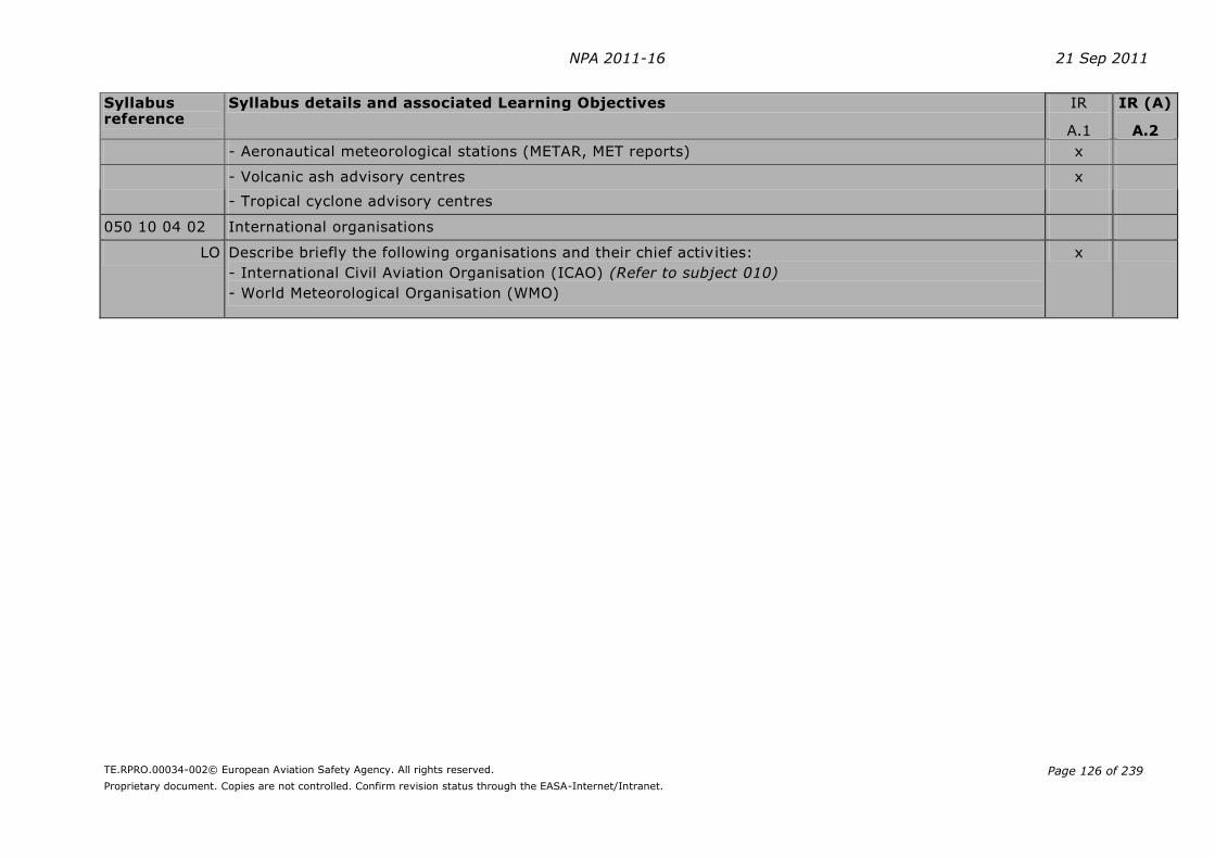
NPA 2011-16 21 Sep 2011
TE.RPRO.00034-002© European Aviation Safety Agency. All rights reserved.
Proprietary document. Copies are not controlled. Confirm revision status through the EASA-Internet/Intranet.
Page 126 of 239
Syllabus reference
Syllabus details and associated Learning Objectives IR
A.1
IR (A)
A.2
- Aeronautical meteorological stations (METAR, MET reports) x
- Volcanic ash advisory centres x
- Tropical cyclone advisory centres
050 10 04 02 International organisations
LO Describe briefly the following organisations and their chief activities:
- International Civil Aviation Organisation (ICAO) (Refer to subject 010)
- World Meteorological Organisation (WMO)
x

NPA 2011-16 21 Sep 2011
TE.RPRO.00034-002© European Aviation Safety Agency. All rights reserved.
Proprietary document. Copies are not controlled. Confirm revision status through the EASA-Internet/Intranet.
Page 127 of 239
AMC6 FCL.615
DETAILED THEORETICAL KNOWLEDGE SYLLABUS AND LEARNING OBJECTIVES Subject Radio Navigation (Competency-based modular course according to Appendix 6 A.2)
Syllabus reference Syllabus details and associated Learning Objectives
IR
A.1
IR (A)
A.2
062 00 00 00
RADIO NAVIGATION
062 01 00 00
BASIC RADIO PROPAGATION THEORY
062 01 01 00
Basic principles
062 01 01 01 Electromagnetic waves
LO State that radio waves travel at the speed of light, being approximately 300 000km/s or 162 000 NM/s x
LO Define a cycle. A complete series of values of a periodical process x
LO Define Hertz. One Hertz is one cycle per second x
062 01 01 02 Frequency, wavelength, amplitude, phase angle
LO Define frequency. The number of cycles occurring in one second in a radio wave expressed in Hertz (Hz) x
LO Define wavelength. The physical distance travelled by a radio wave during one cycle of transmission x
LO Define amplitude. The maximum deflection in an oscillation or wave x
LO State that the relationship between wavelength and frequency is:
wavelength (λ) = speed of light (c) or λ(meters) = 300 000 Frequency (f) kHz
x
LO Define phase. The fraction of one wavelength expressed in degrees from 000° to 360° x
LO Define phase difference/shift. The angular difference between the corresponding points of two cycles of equal wavelength, which is measurable in degrees
x
062 01 01 03 Frequency bands, sidebands, single sideband
LO List the bands of the frequency spectrum for electromagnetic waves: x
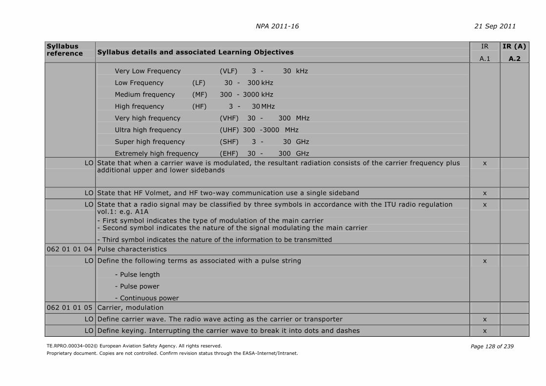
NPA 2011-16 21 Sep 2011
TE.RPRO.00034-002© European Aviation Safety Agency. All rights reserved.
Proprietary document. Copies are not controlled. Confirm revision status through the EASA-Internet/Intranet.
Page 128 of 239
Syllabus reference Syllabus details and associated Learning Objectives
IR
A.1
IR (A)
A.2
Very Low Frequency (VLF) 3 - 30 kHz
Low Frequency (LF) 30 - 300 kHz
Medium frequency (MF) 300 - 3000 kHz
High frequency (HF) 3 - 30 MHz
Very high frequency (VHF) 30 - 300 MHz
Ultra high frequency (UHF) 300 - 3000 MHz
Super high frequency (SHF) 3 - 30 GHz
Extremely high frequency (EHF) 30 - 300 GHz
LO State that when a carrier wave is modulated, the resultant radiation consists of the carrier frequency plus additional upper and lower sidebands
x
LO State that HF Volmet, and HF two-way communication use a single sideband x
LO State that a radio signal may be classified by three symbols in accordance with the ITU radio regulation vol.1: e.g. A1A
- First symbol indicates the type of modulation of the main carrier - Second symbol indicates the nature of the signal modulating the main carrier
- Third symbol indicates the nature of the information to be transmitted
x
062 01 01 04 Pulse characteristics
LO Define the following terms as associated with a pulse string
- Pulse length
- Pulse power
- Continuous power
x
062 01 01 05 Carrier, modulation
LO Define carrier wave. The radio wave acting as the carrier or transporter x
LO Define keying. Interrupting the carrier wave to break it into dots and dashes x

NPA 2011-16 21 Sep 2011
TE.RPRO.00034-002© European Aviation Safety Agency. All rights reserved.
Proprietary document. Copies are not controlled. Confirm revision status through the EASA-Internet/Intranet.
Page 129 of 239
Syllabus reference Syllabus details and associated Learning Objectives
IR
A.1
IR (A)
A.2
LO Define modulation. The technical term for the process of impressing and transporting information by radio waves
x
062 01 01 06 Kinds of modulation (amplitude, frequency, pulse, phase)
LO Define amplitude modulation. The information is impressed onto the carrier wave by altering the amplitude of the carrier
x
LO Define frequency modulation. The information is impressed onto the carrier wave by altering the frequency of the carrier
x
LO Describe pulse modulation. A modulation form used in radar, by transmitting short pulses followed by larger interruptions
x
LO Describe phase modulation. A modulation form used in GPS where the phase of the carrier wave is reversed
x
062 01 02 00
Antennas
062 01 02 01 Characteristics
LO Define antenna. A wave type transducer for the process of converting a line AC into a free electromagnetic wave
x
LO State that the simplest type of antenna is a dipole which is a wire of length equal to one half of the wavelength
x
LO State that in a wire which is fed with an AC (alternating current), some of the power will radiate into space x
LO State that in a wire parallel to the wire fed with an AC but remote from it, an AC will be induced x
LO State that an electromagnetic wave always consists of an oscillating electric (E) and an oscillating magnetic (H) field which propagates at the speed of light
x
LO State that the (E) and (H) fields are perpendicular to each other. The oscillations are perpendicular to the propagation direction and are in phase
x
LO State that the electric field is parallel to the wire and the magnetic field is perpendicular to it x
062 01 02 02 Polarisation
LO State that the polarisation of an electromagnetic wave describes the orientation of the plane of oscillation of the electrical component of the wave with regard to its direction of propagation
x
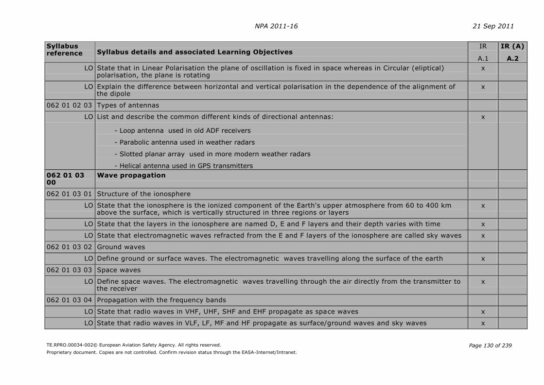
NPA 2011-16 21 Sep 2011
TE.RPRO.00034-002© European Aviation Safety Agency. All rights reserved.
Proprietary document. Copies are not controlled. Confirm revision status through the EASA-Internet/Intranet.
Page 130 of 239
Syllabus reference Syllabus details and associated Learning Objectives
IR
A.1
IR (A)
A.2
LO State that in Linear Polarisation the plane of oscillation is fixed in space whereas in Circular (eliptical) polarisation, the plane is rotating
x
LO Explain the difference between horizontal and vertical polarisation in the dependence of the alignment of the dipole
x
062 01 02 03 Types of antennas
LO List and describe the common different kinds of directional antennas:
- Loop antenna used in old ADF receivers
- Parabolic antenna used in weather radars
- Slotted planar array used in more modern weather radars
- Helical antenna used in GPS transmitters
x
062 01 03 00
Wave propagation
062 01 03 01 Structure of the ionosphere
LO State that the ionosphere is the ionized component of the Earth's upper atmosphere from 60 to 400 km above the surface, which is vertically structured in three regions or layers
x
LO State that the layers in the ionosphere are named D, E and F layers and their depth varies with time x
LO State that electromagnetic waves refracted from the E and F layers of the ionosphere are called sky waves x
062 01 03 02 Ground waves
LO Define ground or surface waves. The electromagnetic waves travelling along the surface of the earth x
062 01 03 03 Space waves
LO Define space waves. The electromagnetic waves travelling through the air directly from the transmitter to the receiver
x
062 01 03 04 Propagation with the frequency bands
LO State that radio waves in VHF, UHF, SHF and EHF propagate as space waves x
LO State that radio waves in VLF, LF, MF and HF propagate as surface/ground waves and sky waves x

NPA 2011-16 21 Sep 2011
TE.RPRO.00034-002© European Aviation Safety Agency. All rights reserved.
Proprietary document. Copies are not controlled. Confirm revision status through the EASA-Internet/Intranet.
Page 131 of 239
Syllabus reference Syllabus details and associated Learning Objectives
IR
A.1
IR (A)
A.2
062 01 03 05 Doppler principle
LO State that Doppler effect is the phenomena that the frequency of an electromagnetic wave will increase or decrease if there is relative motion between the transmitter and the receiver
x
LO State that the frequency will increase if the transmitter and receiver are converging and will decrease if they are diverging
x
062 01 03 06 Factors affecting propagation
LO Define Skip Distance. The distance between the transmitter and the point on the surface of the earth where the first sky return arrives
x
LO State that skip zone/dead space is the distance between the limit of the surface wave and the sky wave x
LO Describe Fading. When a receiver picks up the sky signal and the surface signal, the signals will interfere with each other causing the signals to be cancelled out.
x
LO State that radio waves in the VHF band and above are limited in range as they are not reflected by the ionosphere and do not have a surface wave.
x
LO Describe the physical phenomena reflection, refraction, diffraction, absorption and interference x
062 02 00 00
RADIO AIDS
062 02 01 00
Ground D/F
062 02 01 01 Principles
LO Describe the use of a Ground Direction Finder x
LO Explain why the service provided is subdivided as:
- VHF direction finding (VDF)
- UHF direction finding (UDF)
x
LO Explain the limitation of range because of the path of the VHF signal x
LO Describe the operation of the VDF in the following general terms:
- Radio waves emitted by the radio telephony (R/T) equipment of the aircraft
x
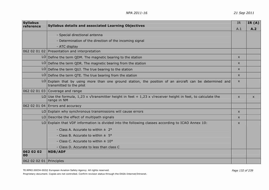
NPA 2011-16 21 Sep 2011
TE.RPRO.00034-002© European Aviation Safety Agency. All rights reserved.
Proprietary document. Copies are not controlled. Confirm revision status through the EASA-Internet/Intranet.
Page 132 of 239
Syllabus reference Syllabus details and associated Learning Objectives
IR
A.1
IR (A)
A.2
- Special directional antenna
- Determination of the direction of the incoming signal
- ATC display
062 02 01 02 Presentation and interpretation
LO Define the term QDM. The magnetic bearing to the station x
LO Define the term QDR. The magnetic bearing from the station x
LO Define the term QUJ. The true bearing to the station x
LO Define the term QTE. The true bearing from the station x
LO Explain that by using more than one ground station, the position of an aircraft can be determined and
transmitted to the pilot
x
062 02 01 03 Coverage and range
LO Use the formula, 1,23 x √transmitter height in feet + 1,23 x √receiver height in feet, to calculate the range in NM
x x
062 02 01 04 Errors and accuracy
LO Explain why synchronous transmissions will cause errors x
LO Describe the effect of multipath signals x
LO Explain that VDF information is divided into the following classes according to ICAO Annex 10:
- Class A. Accurate to within ± 2°
- Class B. Accurate to within ± 5°
- Class C. Accurate to within ± 10°
- Class D. Accurate to less than class C
x
062 02 02 00
NDB/ADF
062 02 02 01 Principles
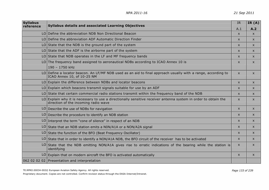
NPA 2011-16 21 Sep 2011
TE.RPRO.00034-002© European Aviation Safety Agency. All rights reserved.
Proprietary document. Copies are not controlled. Confirm revision status through the EASA-Internet/Intranet.
Page 133 of 239
Syllabus reference Syllabus details and associated Learning Objectives
IR
A.1
IR (A)
A.2
LO Define the abbreviation NDB Non Directional Beacon x x
LO Define the abbreviation ADF Automatic Direction Finder x x
LO State that the NDB is the ground part of the system x x
LO State that the ADF is the airborne part of the system x x
LO State that NDB operates in the LF and MF frequency bands x x
LO The frequency band assigned to aeronautical NDBs according to ICAO Annex 10 is
190 – 1750 kHz
x x
LO Define a locator beacon. An LF/MF NDB used as an aid to final approach usually with a range, according to ICAO Annex 10, of 10-25 NM
x x
LO Explain the difference between NDBs and locator beacons x x
LO Explain which beacons transmit signals suitable for use by an ADF x x
LO State that certain commercial radio stations transmit within the frequency band of the NDB x x
LO Explain why it is necessary to use a directionally sensitive receiver antenna system in order to obtain the direction of the incoming radio wave
x x
LO Describe the use of NDBs for navigation x x
LO Describe the procedure to identify an NDB station x x
LO Interpret the term “cone of silence” in respect of an NDB x x
LO State that an NDB station emits a N0N/A1A or a NON/A2A signal x x
LO State the function of the BFO (Beat Frequency Oscillator) x x
LO State that in order to identify a NON/A1A NDB, the BFO circuit of the receiver has to be activated x x
LO State that the NDB emitting NON/A1A gives rise to erratic indications of the bearing while the station is
identifying
x x
LO Explain that on modern aircraft the BFO is activated automatically x x
062 02 02 02 Presentation and interpretation

NPA 2011-16 21 Sep 2011
TE.RPRO.00034-002© European Aviation Safety Agency. All rights reserved.
Proprietary document. Copies are not controlled. Confirm revision status through the EASA-Internet/Intranet.
Page 134 of 239
Syllabus reference Syllabus details and associated Learning Objectives
IR
A.1
IR (A)
A.2
LO Name the types of indicator in common use:
- Electronic navigation display
- Radio Magnetic Indicator RMI
- Fixed card ADF (radio compass)
- Moving card ADF
x x
LO Describe the indications given on RMI, fixed card and moving card ADF displays x x
LO Given a display interpret the relevant ADF information x x
LO Calculate the true bearing from the compass heading and relative bearing x x
LO Convert the compass bearing into magnetic bearing and true bearing x x
LO Describe how to fly the following in-flight ADF procedures according to DOC 8168 Vol.1:
- Homing and tracking and explain the influence of wind
- Interceptions
- Procedural turns
- Holding patterns
x
x
062 02 02 03 Coverage and range
LO State that the power limits the range of an NDB x x
LO Explain the relationship between power and range x
LO State that the range of an NDB over sea is better than over land due to better ground wave propagation over seawater than over land
x x
LO Describe the propagation path of NDB radio waves with respect to the ionosphere and the Earth’s surface x x
LO Explain that interference between sky and ground waves at night leads to “fading” x x
LO Define the accuracy the pilot has to fly the required bearing in order to be considered established during approach according to ICAO DOC 8168 as within ± 5°
x x
LO State that there is no warning indication of NDB failure x x
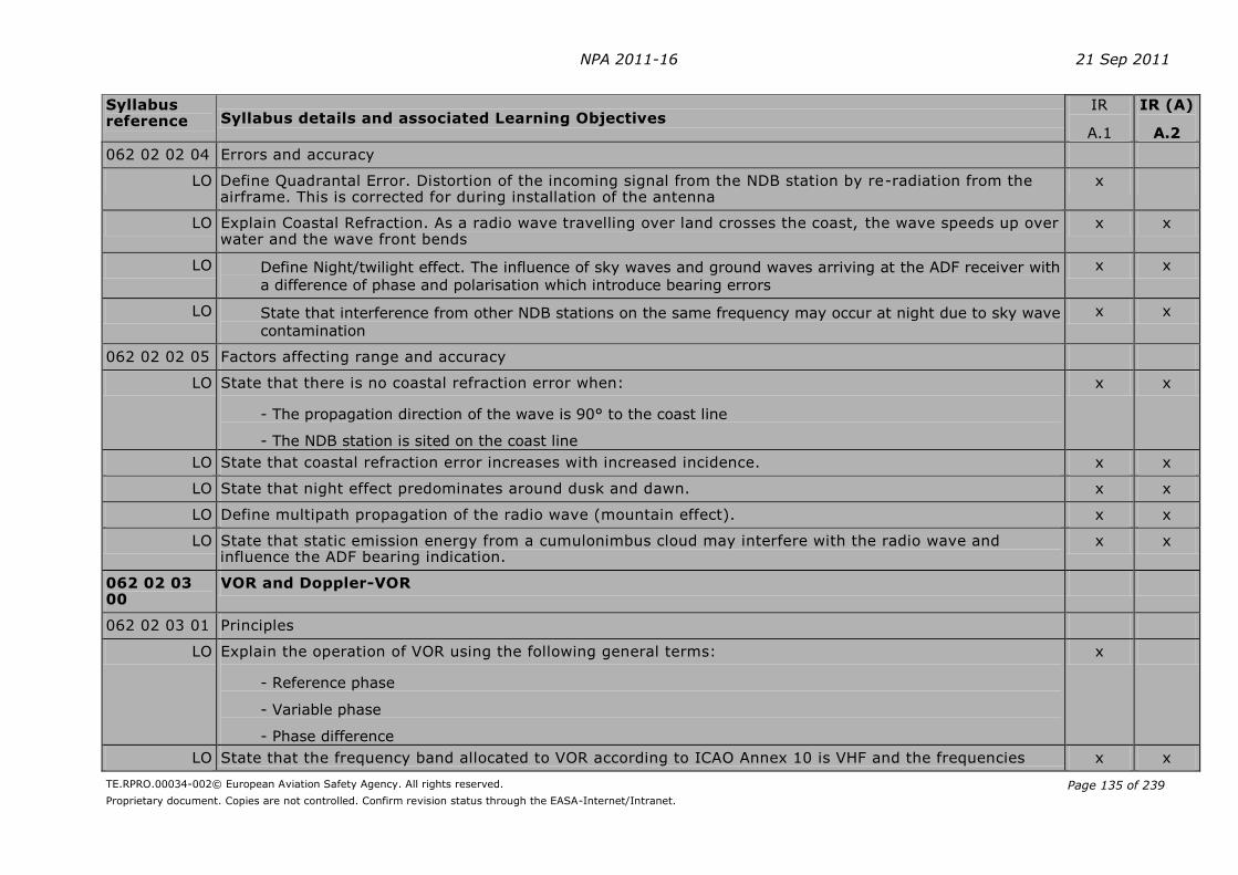
NPA 2011-16 21 Sep 2011
TE.RPRO.00034-002© European Aviation Safety Agency. All rights reserved.
Proprietary document. Copies are not controlled. Confirm revision status through the EASA-Internet/Intranet.
Page 135 of 239
Syllabus reference Syllabus details and associated Learning Objectives
IR
A.1
IR (A)
A.2
062 02 02 04 Errors and accuracy
LO Define Quadrantal Error. Distortion of the incoming signal from the NDB station by re-radiation from the airframe. This is corrected for during installation of the antenna
x
LO Explain Coastal Refraction. As a radio wave travelling over land crosses the coast, the wave speeds up over water and the wave front bends
x x
LO Define Night/twilight effect. The influence of sky waves and ground waves arriving at the ADF receiver with
a difference of phase and polarisation which introduce bearing errors
x x
LO State that interference from other NDB stations on the same frequency may occur at night due to sky wave
contamination
x x
062 02 02 05 Factors affecting range and accuracy
LO State that there is no coastal refraction error when:
- The propagation direction of the wave is 90° to the coast line
- The NDB station is sited on the coast line
x x
LO State that coastal refraction error increases with increased incidence. x x
LO State that night effect predominates around dusk and dawn. x x
LO Define multipath propagation of the radio wave (mountain effect). x x
LO State that static emission energy from a cumulonimbus cloud may interfere with the radio wave and influence the ADF bearing indication.
x x
062 02 03 00
VOR and Doppler-VOR
062 02 03 01 Principles
LO Explain the operation of VOR using the following general terms:
- Reference phase
- Variable phase
- Phase difference
x
LO State that the frequency band allocated to VOR according to ICAO Annex 10 is VHF and the frequencies x x

NPA 2011-16 21 Sep 2011
TE.RPRO.00034-002© European Aviation Safety Agency. All rights reserved.
Proprietary document. Copies are not controlled. Confirm revision status through the EASA-Internet/Intranet.
Page 136 of 239
Syllabus reference Syllabus details and associated Learning Objectives
IR
A.1
IR (A)
A.2 used are 108.0 – 117.975 MHz.
LO State that frequencies in the allocated VOR range with the first decimal place an odd number, are used by ILS
x x
LO State that the following types of VOR are in operation:
- Conventional VOR (CVOR) a first generation VOR station emitting signals by means of a rotating antenna
- Doppler VOR (DVOR) a second generation VOR station emitting signals by means of a combination of fixed
antennas utilising the Doppler principle
- En-route VOR for use by IFR traffic
- Terminal VOR (TVOR) a station with a shorter range used as part of the approach and departure structure at
major airports
- Test VOR (VOT) a VOR station emitting a signal to test VOR indicators in an aircraft
x x
LO Describe how ATIS information is transmitted on VOR frequencies. x x
LO List the three main components of VOR airborne equipment:
- The antenna
- The receiver
- The indicator
x x
LO Describe the identification of a VOR in terms of Morse-code letters, continuous tone or dots (VOT), tone pitch, repetition rate and additional plain text
x x
LO State that according to ICAO Annex 10, a VOR station has an automatic ground monitoring system x
LO State that the VOR monitoring system monitors change in measured radial and reduction in signal strength x
LO State that failure of the VOR station to stay within the required limits can cause the removal of identification and navigation components from the carrier or radiation to cease
x x
062 02 03 02 Presentation and interpretation
LO Read off the radial on a Radio Magnetic Indicator (RMI) x x
LO Read off the angular displacement, in relation to a pre-selected radial on an HSI or CDI x x
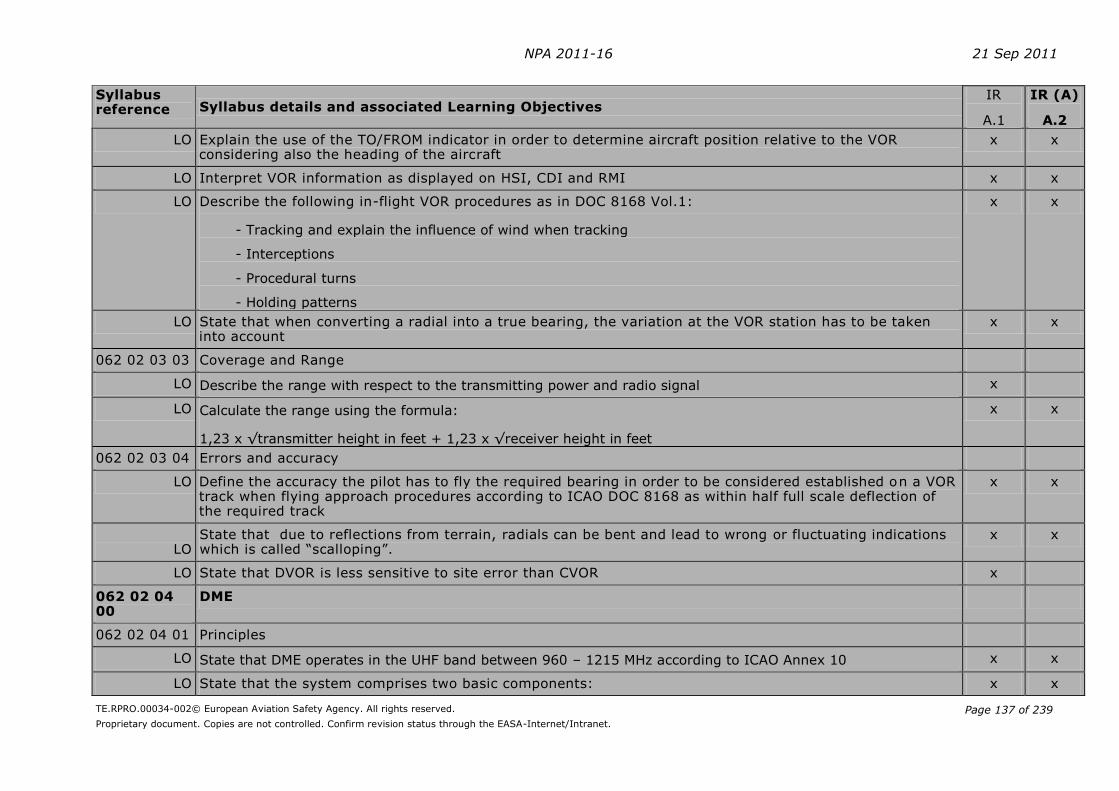
NPA 2011-16 21 Sep 2011
TE.RPRO.00034-002© European Aviation Safety Agency. All rights reserved.
Proprietary document. Copies are not controlled. Confirm revision status through the EASA-Internet/Intranet.
Page 137 of 239
Syllabus reference Syllabus details and associated Learning Objectives
IR
A.1
IR (A)
A.2
LO Explain the use of the TO/FROM indicator in order to determine aircraft position relative to the VOR considering also the heading of the aircraft
x x
LO Interpret VOR information as displayed on HSI, CDI and RMI x x
LO Describe the following in-flight VOR procedures as in DOC 8168 Vol.1:
- Tracking and explain the influence of wind when tracking
- Interceptions
- Procedural turns
- Holding patterns
x x
LO State that when converting a radial into a true bearing, the variation at the VOR station has to be taken into account
x x
062 02 03 03 Coverage and Range
LO Describe the range with respect to the transmitting power and radio signal x
LO Calculate the range using the formula:
1,23 x √transmitter height in feet + 1,23 x √receiver height in feet
x x
062 02 03 04 Errors and accuracy
LO Define the accuracy the pilot has to fly the required bearing in order to be considered established on a VOR track when flying approach procedures according to ICAO DOC 8168 as within half full scale deflection of the required track
x x
LO
State that due to reflections from terrain, radials can be bent and lead to wrong or fluctuating indications which is called “scalloping”.
x x
LO State that DVOR is less sensitive to site error than CVOR x
062 02 04 00
DME
062 02 04 01 Principles
LO State that DME operates in the UHF band between 960 – 1215 MHz according to ICAO Annex 10 x x
LO State that the system comprises two basic components: x x

NPA 2011-16 21 Sep 2011
TE.RPRO.00034-002© European Aviation Safety Agency. All rights reserved.
Proprietary document. Copies are not controlled. Confirm revision status through the EASA-Internet/Intranet.
Page 138 of 239
Syllabus reference Syllabus details and associated Learning Objectives
IR
A.1
IR (A)
A.2
- The aircraft component, the interrogator
- The ground component, the transponder
LO Describe the principle of distance measurement using DME in terms of:
- Pulse pairs
- Fixed frequency division of 63 MHz
- Propagation delay
- 50 microsecond delay time
- Irregular transmission sequence
- Search mode
- Tracking mode
- Memory mode
x
LO State that the distance measured by DME is slant range x x
LO Illustrate that a position line using DME is a circle with the station at its centre x x
LO Describe how the pairing of VHF and UHF frequencies (VOR/DME) enables selection of two items of navigation information from one frequency setting
x x
LO Describe, in the case of co-location, the frequency pairing and identification procedure x x
LO Explain that depending on the configuration, the combination of a DME distance with a VOR radial can determine the position of the aircraft
x x
LO Explain that military TACAN stations may be used for DME information x x
062 02 04 02 Presentation and interpretation
LO Explain that when identifying a DME station co-located with a VOR station, the identification signal with the higher tone frequency is the DME which idents approximately every 40 seconds
x x
LO Calculate ground distance given slant range and altitude x x
LO Describe the use of DME to fly a DME arc in accordance with DOC 8168 Vol. 1 x x
LO State that a DME system may have a groundspeed read out combined with the DME read out x x
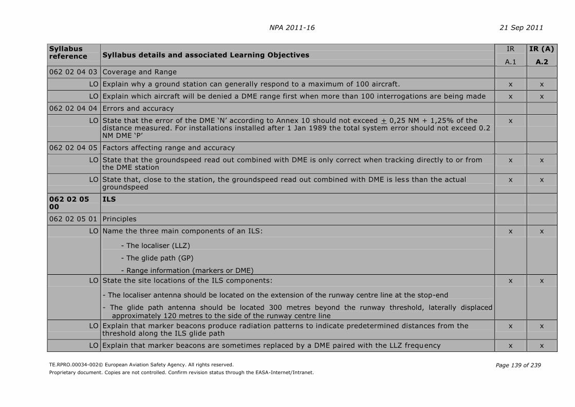
NPA 2011-16 21 Sep 2011
TE.RPRO.00034-002© European Aviation Safety Agency. All rights reserved.
Proprietary document. Copies are not controlled. Confirm revision status through the EASA-Internet/Intranet.
Page 139 of 239
Syllabus reference Syllabus details and associated Learning Objectives
IR
A.1
IR (A)
A.2
062 02 04 03 Coverage and Range
LO Explain why a ground station can generally respond to a maximum of 100 aircraft. x x
LO Explain which aircraft will be denied a DME range first when more than 100 interrogations are being made x x
062 02 04 04 Errors and accuracy
LO State that the error of the DME ‘N’ according to Annex 10 should not exceed + 0,25 NM + 1,25% of the distance measured. For installations installed after 1 Jan 1989 the total system error should not exceed 0.2 NM DME ‘P’
x
062 02 04 05 Factors affecting range and accuracy
LO State that the groundspeed read out combined with DME is only correct when tracking directly to or from the DME station
x x
LO State that, close to the station, the groundspeed read out combined with DME is less than the actual groundspeed
x x
062 02 05 00
ILS
062 02 05 01 Principles
LO Name the three main components of an ILS:
- The localiser (LLZ)
- The glide path (GP)
- Range information (markers or DME)
x x
LO State the site locations of the ILS components:
- The localiser antenna should be located on the extension of the runway centre line at the stop-end
- The glide path antenna should be located 300 metres beyond the runway threshold, laterally displaced
approximately 120 metres to the side of the runway centre line
x x
LO Explain that marker beacons produce radiation patterns to indicate predetermined distances from the threshold along the ILS glide path
x x
LO Explain that marker beacons are sometimes replaced by a DME paired with the LLZ frequency x x
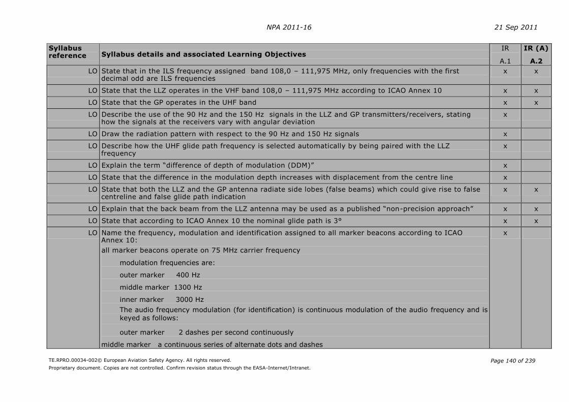
NPA 2011-16 21 Sep 2011
TE.RPRO.00034-002© European Aviation Safety Agency. All rights reserved.
Proprietary document. Copies are not controlled. Confirm revision status through the EASA-Internet/Intranet.
Page 140 of 239
Syllabus reference Syllabus details and associated Learning Objectives
IR
A.1
IR (A)
A.2
LO State that in the ILS frequency assigned band 108,0 – 111,975 MHz, only frequencies with the first decimal odd are ILS frequencies
x x
LO State that the LLZ operates in the VHF band 108,0 – 111,975 MHz according to ICAO Annex 10 x x
LO State that the GP operates in the UHF band x x
LO Describe the use of the 90 Hz and the 150 Hz signals in the LLZ and GP transmitters/receivers, stating how the signals at the receivers vary with angular deviation
x
LO Draw the radiation pattern with respect to the 90 Hz and 150 Hz signals x
LO Describe how the UHF glide path frequency is selected automatically by being paired with the LLZ frequency
x
LO Explain the term “difference of depth of modulation (DDM)” x
LO State that the difference in the modulation depth increases with displacement from the centre line x
LO State that both the LLZ and the GP antenna radiate side lobes (false beams) which could give rise to false centreline and false glide path indication
x x
LO Explain that the back beam from the LLZ antenna may be used as a published “non-precision approach” x x
LO State that according to ICAO Annex 10 the nominal glide path is 3° x x
LO Name the frequency, modulation and identification assigned to all marker beacons according to ICAO Annex 10:
all marker beacons operate on 75 MHz carrier frequency
modulation frequencies are:
outer marker 400 Hz
middle marker 1300 Hz
inner marker 3000 Hz
The audio frequency modulation (for identification) is continuous modulation of the audio frequency and is
keyed as follows:
outer marker 2 dashes per second continuously
middle marker a continuous series of alternate dots and dashes
x

NPA 2011-16 21 Sep 2011
TE.RPRO.00034-002© European Aviation Safety Agency. All rights reserved.
Proprietary document. Copies are not controlled. Confirm revision status through the EASA-Internet/Intranet.
Page 141 of 239
Syllabus reference Syllabus details and associated Learning Objectives
IR
A.1
IR (A)
A.2
inner marker 6 dots per second continuously
LO State that according to ICAO DOC 8168, the final approach area contains a fix or facility that permits verification of the ILS glide path/altimeter relationship. The outer marker or DME is usually used for this purpose.
x x
062 02 05 02 Presentation and interpretation
LO Describe the ILS identification regarding frequency and Morse code and/or plain text x x
LO Calculate the rate of descent for a 3° glide path angle given the groundspeed of the aircraft using the formula:
Rate of descent (ROD) in ft/min = groundspeed in kt x 10 2
x x
LO Calculate the rate of descent using the following formula when flying any glide path angle:
ROD ft/min = Speed factor (SF) x glide path angle x 100
x x
LO Interpret the markers by sound, modulation, and frequency x x
LO State that the outer marker cockpit indicator is coloured blue, the middle marker amber and the inner marker white
x x
LO State that in accordance with ICAO Annex 10 an ILS installation has an automatic ground monitoring system
x
LO State that the LLZ and GP monitoring system monitors any shift in the LLZ and GP mean course line or reduction in signal strength
x
LO State that a failure of either the LLZ or the GP to stay within predetermined limits will cause:
- Removal of identification and navigation components from the carrier - Radiation to cease
- A warning to be displayed at the designated control point
x x
LO State that an ILS receiver has an automatic monitoring function x x
LO Describe the circumstances in which warning flags will appear for both the LLZ and the GP:
- Absence of the carrier frequency - Absence of the 90 and 150 Hz modulation simultaneously - The percentage modulation of either the 90 or 150 Hz signal reduced to zero
x

NPA 2011-16 21 Sep 2011
TE.RPRO.00034-002© European Aviation Safety Agency. All rights reserved.
Proprietary document. Copies are not controlled. Confirm revision status through the EASA-Internet/Intranet.
Page 142 of 239
Syllabus reference Syllabus details and associated Learning Objectives
IR
A.1
IR (A)
A.2
LO Interpret the indications on a Course Deviation Indicator (CDI) and a Horizontal Situation Indicator (HSI):
- Full scale deflection of the CDI needle corresponds to approximately 2,5° displacement from the ILS centre line
- Full scale deflection on the GP corresponds to approximately 0,7° from the ILS GP centre line
x x
LO Interpret the aircraft’s position in relation to the extended runway centre line on a back-beam approach x x
LO Explain the setting of the course pointer of an HSI for front-beam and back-beam approaches x x
062 02 05 03 Coverage and Range
LO Sketch the standard coverage area of the LLZ and GP with angular sector limits in degrees and distance limits from the transmitter in accordance with ICAO Annex 10:
- LLZ coverage area is 10° on either side of the centre line to a distance of 25 NM from the runway, and 35° on
either side of the centre line to a distance of 17 NM from the runway
- GP coverage area is 8° on either side of the centre line to a distance of minimum 10 NM from the runway
x x
062 02 05 04 Errors and accuracy
LO Explain that ILS approaches are divided into facility performance categories defined in ICAO Annex 10 x x
LO Define the following ILS operation categories:
- Category I
- Category II
- Category IIIA
- Category IIIB
- Category IIIC
x
LO Explain that all category III ILS operations guidance information is provided from the coverage limits of the facility to, and along, the surface of the runway
x
LO Explain why the accuracy requirements are progressively higher for CAT I, CAT II and CAT III ILS x
LO State the vertical accuracy requirements above the threshold for CAT I, II and III for the signals of the ILS ground installation
x
LO Explain the following in accordance with ICAO DOC 8168: x x

NPA 2011-16 21 Sep 2011
TE.RPRO.00034-002© European Aviation Safety Agency. All rights reserved.
Proprietary document. Copies are not controlled. Confirm revision status through the EASA-Internet/Intranet.
Page 143 of 239
Syllabus reference Syllabus details and associated Learning Objectives
IR
A.1
IR (A)
A.2
- The accuracy the pilot has to fly the ILS localiser to be considered established on an ILS track is within half full
scale deflection of the required track
- The aircraft has to be established within half scale deflection of the LLZ before starting descent on the GP
- The pilot has to fly the ILS GP to a maximum of half scale fly-up deflection of the GP in order to stay in
protected airspace
LO State that if a pilot deviates by more than half scale deflection on the LLZ or by more than half course fly-up deflection on the GP, an immediate missed approach should be executed, because obstacle clearance may no longer be guaranteed
x x
LO Describe ILS beam bends. Deviations from the nominal position of the LLZ and GP respectively. They are ascertained by flight test.
x
LO Explain multipath interference. Reflections from large objects within the ILS coverage area x
062 02 05 05 Factors affecting range and accuracy
LO Define the ILS critical Area. An area of defined dimensions about the LLZ and GP antennas where vehicles, including aircraft, are excluded during all ILS operations
x
LO Define the ILS sensitive area. An area extending beyond the critical area where the parking and/or movement of vehicles, including aircraft, is controlled to prevent the possibility of unacceptable interference to the ILS signal during ILS operations
x
LO Describe the effect of FM broadcast stations that transmit on frequencies just below 108 MHz x
062 02 06 00
MLS
062 02 06 01 Principles
LO Explain the Principle of operation:
- Horizontal course guidance during the approach
- Vertical guidance during the approach
- Horizontal guidance for departure and missed approach
- DME (DME/P) distance
- Transmission of special information regarding the system and the approach conditions
x
LO State that MLS operates in the S band on 200 channels x
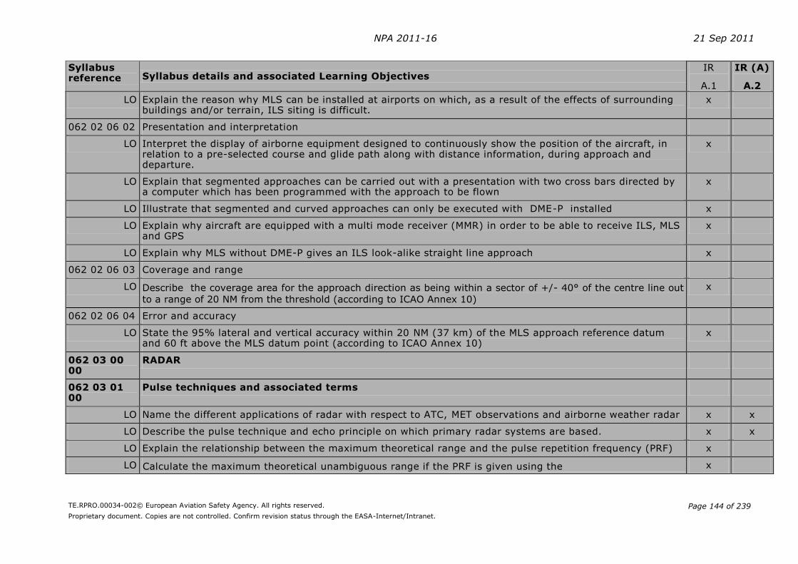
NPA 2011-16 21 Sep 2011
TE.RPRO.00034-002© European Aviation Safety Agency. All rights reserved.
Proprietary document. Copies are not controlled. Confirm revision status through the EASA-Internet/Intranet.
Page 144 of 239
Syllabus reference Syllabus details and associated Learning Objectives
IR
A.1
IR (A)
A.2
LO Explain the reason why MLS can be installed at airports on which, as a result of the effects of surrounding buildings and/or terrain, ILS siting is difficult.
x
062 02 06 02 Presentation and interpretation
LO Interpret the display of airborne equipment designed to continuously show the position of the aircraft, in relation to a pre-selected course and glide path along with distance information, during approach and departure.
x
LO Explain that segmented approaches can be carried out with a presentation with two cross bars directed by a computer which has been programmed with the approach to be flown
x
LO Illustrate that segmented and curved approaches can only be executed with DME-P installed x
LO Explain why aircraft are equipped with a multi mode receiver (MMR) in order to be able to receive ILS, MLS and GPS
x
LO Explain why MLS without DME-P gives an ILS look-alike straight line approach x
062 02 06 03 Coverage and range
LO Describe the coverage area for the approach direction as being within a sector of +/- 40° of the centre line out
to a range of 20 NM from the threshold (according to ICAO Annex 10)
x
062 02 06 04 Error and accuracy
LO State the 95% lateral and vertical accuracy within 20 NM (37 km) of the MLS approach reference datum and 60 ft above the MLS datum point (according to ICAO Annex 10)
x
062 03 00 00
RADAR
062 03 01 00
Pulse techniques and associated terms
LO Name the different applications of radar with respect to ATC, MET observations and airborne weather radar x x
LO Describe the pulse technique and echo principle on which primary radar systems are based. x x
LO Explain the relationship between the maximum theoretical range and the pulse repetition frequency (PRF) x
LO Calculate the maximum theoretical unambiguous range if the PRF is given using the x

NPA 2011-16 21 Sep 2011
TE.RPRO.00034-002© European Aviation Safety Agency. All rights reserved.
Proprietary document. Copies are not controlled. Confirm revision status through the EASA-Internet/Intranet.
Page 145 of 239
Syllabus reference Syllabus details and associated Learning Objectives
IR
A.1
IR (A)
A.2
formula: 2PRF
000 300 kmin range
LO Calculate the PRF if the maximum theoretical unambiguous range of the radar is given using the formula:
2 (km) range
000 300 PRF
x
LO Explain that pulse length defines the minimum theoretical range of a radar x
LO Explain the need to harmonise the rotation speed of the antenna, the pulse length and the pulse repetition frequency for range.
x
LO Describe, in general terms, the effects of the following factors with respect to the quality of the target depiction
on the radar display:
- Atmospheric conditions; super refraction and sub refraction
- Attenuation with distance - Condition and size of the reflecting surface
x x
062 03 02 00
Ground Radar
062 03 02 01 Principles
LO Explain that primary radar provides bearing and distance of targets. x x
LO Explain that primary ground radar is used to detect aircraft that are not equipped with a secondary radar
transponder.
x x
LO Explain why Moving Target Indicator (MTI) is used x x
062 03 02 02 Presentation and interpretation
LO State that modern ATC systems use computer generated display. x x
LO Explain that the radar display enables the ATS controller to provide information, surveillance or guidance service.
x x
062 03 03 00
Airborne Weather Radar
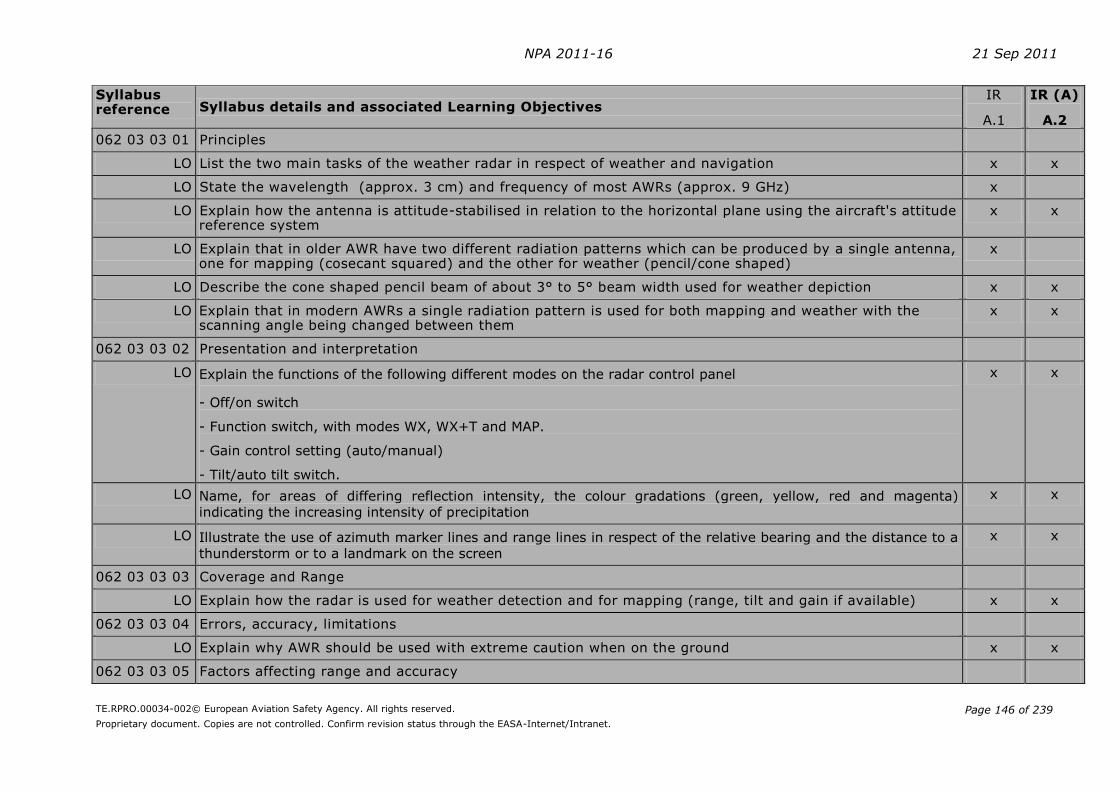
NPA 2011-16 21 Sep 2011
TE.RPRO.00034-002© European Aviation Safety Agency. All rights reserved.
Proprietary document. Copies are not controlled. Confirm revision status through the EASA-Internet/Intranet.
Page 146 of 239
Syllabus reference Syllabus details and associated Learning Objectives
IR
A.1
IR (A)
A.2
062 03 03 01 Principles
LO List the two main tasks of the weather radar in respect of weather and navigation x x
LO State the wavelength (approx. 3 cm) and frequency of most AWRs (approx. 9 GHz) x
LO Explain how the antenna is attitude-stabilised in relation to the horizontal plane using the aircraft's attitude reference system
x x
LO Explain that in older AWR have two different radiation patterns which can be produced by a single antenna, one for mapping (cosecant squared) and the other for weather (pencil/cone shaped)
x
LO Describe the cone shaped pencil beam of about 3° to 5° beam width used for weather depiction x x
LO Explain that in modern AWRs a single radiation pattern is used for both mapping and weather with the scanning angle being changed between them
x x
062 03 03 02 Presentation and interpretation
LO Explain the functions of the following different modes on the radar control panel
- Off/on switch
- Function switch, with modes WX, WX+T and MAP.
- Gain control setting (auto/manual)
- Tilt/auto tilt switch.
x x
LO Name, for areas of differing reflection intensity, the colour gradations (green, yellow, red and magenta)
indicating the increasing intensity of precipitation
x x
LO Illustrate the use of azimuth marker lines and range lines in respect of the relative bearing and the distance to a
thunderstorm or to a landmark on the screen
x x
062 03 03 03 Coverage and Range
LO Explain how the radar is used for weather detection and for mapping (range, tilt and gain if available) x x
062 03 03 04 Errors, accuracy, limitations
LO Explain why AWR should be used with extreme caution when on the ground x x
062 03 03 05 Factors affecting range and accuracy
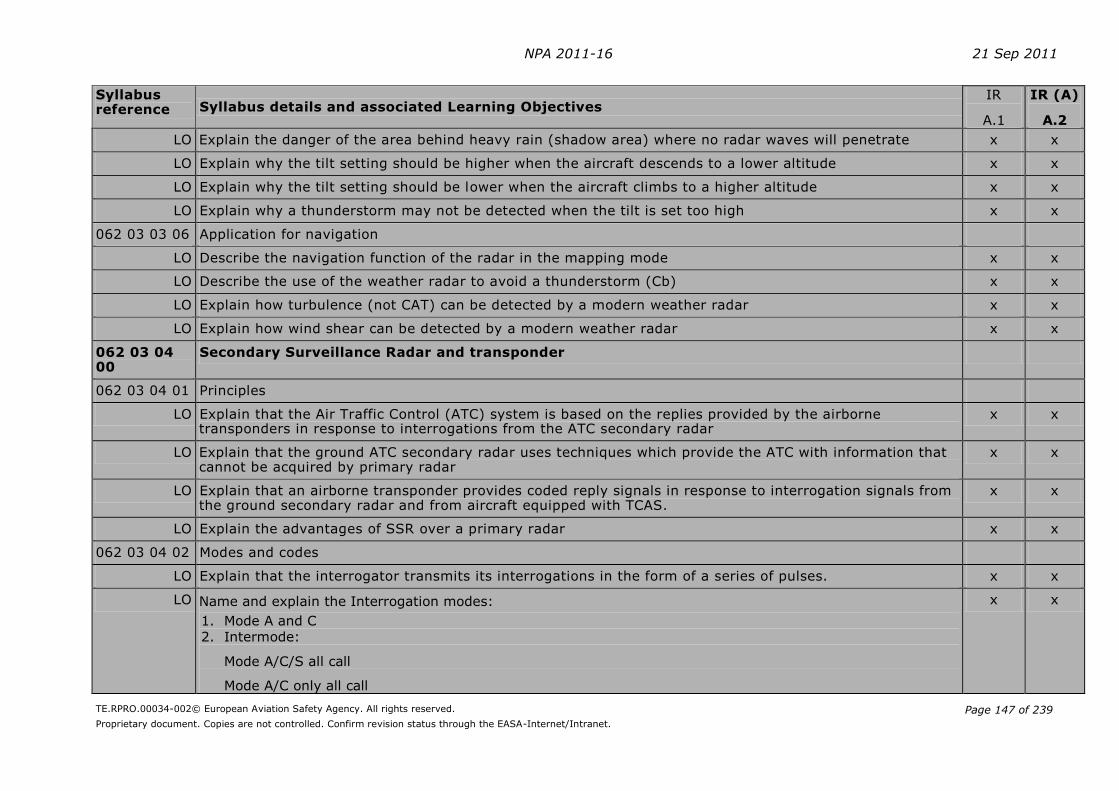
NPA 2011-16 21 Sep 2011
TE.RPRO.00034-002© European Aviation Safety Agency. All rights reserved.
Proprietary document. Copies are not controlled. Confirm revision status through the EASA-Internet/Intranet.
Page 147 of 239
Syllabus reference Syllabus details and associated Learning Objectives
IR
A.1
IR (A)
A.2
LO Explain the danger of the area behind heavy rain (shadow area) where no radar waves will penetrate x x
LO Explain why the tilt setting should be higher when the aircraft descends to a lower altitude x x
LO Explain why the tilt setting should be lower when the aircraft climbs to a higher altitude x x
LO Explain why a thunderstorm may not be detected when the tilt is set too high x x
062 03 03 06 Application for navigation
LO Describe the navigation function of the radar in the mapping mode x x
LO Describe the use of the weather radar to avoid a thunderstorm (Cb) x x
LO Explain how turbulence (not CAT) can be detected by a modern weather radar x x
LO Explain how wind shear can be detected by a modern weather radar x x
062 03 04 00
Secondary Surveillance Radar and transponder
062 03 04 01 Principles
LO Explain that the Air Traffic Control (ATC) system is based on the replies provided by the airborne transponders in response to interrogations from the ATC secondary radar
x x
LO Explain that the ground ATC secondary radar uses techniques which provide the ATC with information that cannot be acquired by primary radar
x x
LO Explain that an airborne transponder provides coded reply signals in response to interrogation signals from the ground secondary radar and from aircraft equipped with TCAS.
x x
LO Explain the advantages of SSR over a primary radar x x
062 03 04 02 Modes and codes
LO Explain that the interrogator transmits its interrogations in the form of a series of pulses. x x
LO Name and explain the Interrogation modes:
1. Mode A and C 2. Intermode:
Mode A/C/S all call
Mode A/C only all call
x x
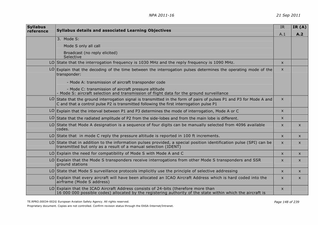
NPA 2011-16 21 Sep 2011
TE.RPRO.00034-002© European Aviation Safety Agency. All rights reserved.
Proprietary document. Copies are not controlled. Confirm revision status through the EASA-Internet/Intranet.
Page 148 of 239
Syllabus reference Syllabus details and associated Learning Objectives
IR
A.1
IR (A)
A.2
3. Mode S:
Mode S only all call
Broadcast (no reply elicited) Selective
LO State that the interrogation frequency is 1030 MHz and the reply frequency is 1090 MHz. x
LO Explain that the decoding of the time between the interrogation pulses determines the operating mode of the
transponder:
- Mode A: transmission of aircraft transponder code
- Mode C: transmission of aircraft pressure altitude - Mode S: aircraft selection and transmission of flight data for the ground surveillance
x
LO State that the ground interrogation signal is transmitted in the form of pairs of pulses P1 and P3 for Mode A and
C and that a control pulse P2 is transmitted following the first interrogation pulse P1
x
LO Explain that the interval between P1 and P3 determines the mode of interrogation, Mode A or C x
LO State that the radiated amplitude of P2 from the side-lobes and from the main lobe is different. x
LO State that Mode A designation is a sequence of four digits can be manually selected from 4096 available codes.
x x
LO State that in mode C reply the pressure altitude is reported in 100 ft increments. x x
LO State that in addition to the information pulses provided, a special position identification pulse (SPI) can be transmitted but only as a result of a manual selection (IDENT)
x x
LO Explain the need for compatibility of Mode S with Mode A and C x x
LO Explain that the Mode S transponders receive interrogations from other Mode S transponders and SSR ground stations
x x
LO State that Mode S surveillance protocols implicitly use the principle of selective addressing x x
LO Explain that every aircraft will have been allocated an ICAO Aircraft Address which is hard coded into the airframe (Mode S address)
x x
LO Explain that the ICAO Aircraft Address consists of 24-bits (therefore more than 16 000 000 possible codes) allocated by the registering authority of the state within which the aircraft is
x
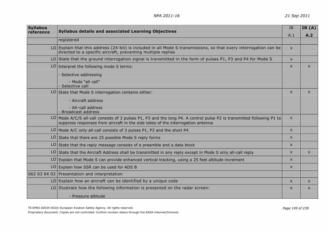
NPA 2011-16 21 Sep 2011
TE.RPRO.00034-002© European Aviation Safety Agency. All rights reserved.
Proprietary document. Copies are not controlled. Confirm revision status through the EASA-Internet/Intranet.
Page 149 of 239
Syllabus reference Syllabus details and associated Learning Objectives
IR
A.1
IR (A)
A.2 registered
LO Explain that this address (24-bit) is included in all Mode S transmissions, so that every interrogation can be directed to a specific aircraft, preventing multiple replies
x
LO State that the ground interrogation signal is transmitted in the form of pulses P1, P3 and P4 for Mode S x
LO Interpret the following mode S terms:
- Selective addressing
- Mode “all call” - Selective call
x x
LO State that Mode S interrogation contains either:
- Aircraft address
- All–call address - Broadcast address
x x
LO Mode A/C/S all-call consists of 3 pulses P1, P3 and the long P4. A control pulse P2 is transmitted following P1 to
suppress responses from aircraft in the side lobes of the interrogation antenna
x
LO Mode A/C only all-call consists of 3 pulses P1, P3 and the short P4 x
LO State that there are 25 possible Mode S reply forms x
LO State that the reply message consists of a preamble and a data block x
LO State that the Aircraft Address shall be transmitted in any reply except in Mode S only all-call reply x x
LO Explain that Mode S can provide enhanced vertical tracking, using a 25 feet altitude increment x
LO Explain how SSR can be used for ADS B x
062 03 04 03 Presentation and interpretation
LO Explain how an aircraft can be identified by a unique code x x
LO Illustrate how the following information is presented on the radar screen:
- Pressure altitude
x x
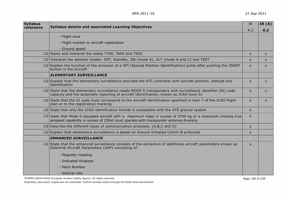
NPA 2011-16 21 Sep 2011
TE.RPRO.00034-002© European Aviation Safety Agency. All rights reserved.
Proprietary document. Copies are not controlled. Confirm revision status through the EASA-Internet/Intranet.
Page 150 of 239
Syllabus reference Syllabus details and associated Learning Objectives
IR
A.1
IR (A)
A.2
- Flight level
- Flight number or aircraft registration
- Ground speed
LO Name and interpret the codes 7700, 7600 and 7500 x x
LO Interpret the selector modes: OFF, Standby, ON (mode A), ALT (mode A and C) and TEST x x
LO Explain the function of the emission of a SPI (Special Position Identification) pulse after pushing the IDENT button in the aircraft
x x
ELEMENTARY SURVEILLANCE
LO Explain that the elementary surveillance provides the ATC controller with aircraft position, altitude and identification
x x
LO State that the elementary surveillance needs MODE S transponders with surveillance identifier (SI) code capacity and the automatic reporting of aircraft identification, known as ICAO level 2s
x x
LO State that the SI code must correspond to the aircraft identification specified in item 7 of the ICAO flight plan or to the registration marking
x x
LO State that only the ICAO identification format is compatible with the ATS ground system x
LO State that Mode S equipped aircraft with a maximum mass in excess of 5700 kg or a maximum cruising true
airspeed capability in excess of 250kt must operate with transponder antenna diversity
x
LO Describe the different types of communication protocols. (A,B,C and D) x
LO Explain that elementary surveillance is based on Ground Initiated Comm-B protocols x
ENHANCED SURVEILLANCE
LO State that the enhanced surveillance consists of the extraction of additional aircraft parameters known as Downlink Aircraft Parameters (DAP) consisting of:
- Magnetic Heading
- Indicated Airspeed
- Mach Number
- Vertical rate
x

NPA 2011-16 21 Sep 2011
TE.RPRO.00034-002© European Aviation Safety Agency. All rights reserved.
Proprietary document. Copies are not controlled. Confirm revision status through the EASA-Internet/Intranet.
Page 151 of 239
Syllabus reference Syllabus details and associated Learning Objectives
IR
A.1
IR (A)
A.2
- Roll angle
- Track Angle Rate
- True Track Angle
- Groundspeed
- Selected Altitude
LO Explain that the controller’s information is improved by providing actual aircraft derived data such as Magnetic Heading, Indicated Airspeed, Vertical Rate and Selected Altitude
x
LO Explain that the automatic extraction of an aircraft’s parameters, and their presentation to the controller, will reduce their R/T workload and will free them to concentrate on ensuring the safe and efficient passage of air traffic
x
LO Explain that the reduction in radio telephony between the air traffic controllers and the pilots will reduce the workload on a pilot and remove a potential source of error
x
062 03 04 04 Errors and Accuracy
LO Explain the following disadvantages of SSR (mode A/C):
- Code garbling of aircraft less than 1.7 NM apart measured in the vertical plane perpendicular to and from the
antenna
- “Fruiting” which results from reception of replies caused by interrogations from other radar stations
x x
062 05 00 00
AREA NAVIGATION SYSTEMS, RNAV/FMS
062 05 01 00
General philosophy and definitions
062 05 01 01 Basic RNAV (B-RNAV)/precision RNAV (P-RNAV)/ RNP-PNAV
LO Define area navigation RNAV (ICAO Annex 11). A method of navigation permitting aircraft operations on any desired track within the coverage of station-referenced navigation signal, or within the limits of a self-contained navigation system
x x
LO State that basic RNAV (B-RNAV) systems require RNP 5 x x
LO State that precision RNAV (PRNAV) systems require RNP 1 x x

NPA 2011-16 21 Sep 2011
TE.RPRO.00034-002© European Aviation Safety Agency. All rights reserved.
Proprietary document. Copies are not controlled. Confirm revision status through the EASA-Internet/Intranet.
Page 152 of 239
Syllabus reference Syllabus details and associated Learning Objectives
IR
A.1
IR (A)
A.2
062 05 01 02 Principles of 2D RNAV, 3D RNAV and 4D RNAV
LO State that a 2D RNAV system is able to navigate in the horizontal plane only. x x
LO State that a 3D RNAV system is able to navigate in the horizontal plane and in addition has a guidance capability in the vertical plane.
x x
LO State that a 4D RNAV system is able to navigate in the horizontal plane, has a guidance capability in the vertical plane and in addition has a timing function
x x
062 05 01 03 Required Navigation Performance (RNP) in accordance with ICAO DOC 9613
LO State that RNP is a concept that applies to navigation performance within an airspace x x
LO The RNP type is based on the navigation performance accuracy to be achieved within the airspace. x x
LO State that RNP X requires a navigation performance accuracy of X NM both lateral and longitudinal 95% of the flying time. (RNP 1 requires a navigation performance of 1 NM both lateral and longitudinal 95% of the flying time)
x x
LO State that RNAV equipment is one requirement, in order to receive approval to operate in a RNP environment
x x
LO State that RNAV equipment operates by automatically determining the aircraft position. x x
LO State the advantages of using RNAV techniques over more conventional forms of navigation:
- Establishment of more direct routes permitting a reduction in flight distance
- Establishment of dual or parallel routes to accommodate a greater flow of en-route traffic
- Establishment of bypass routes for aircraft over flying high-density terminal areas
- Establishment of alternatives or contingency routes on either a planned or ad hoc basis
- Establishment of optimum locations for holding patterns
- Reduction in the number of ground navigation facilities
x x
LO State that RNP may be specified for a route, a number of routes, an area, volume of airspace or any airspace of defined dimensions.
x x
LO State that airborne navigation equipment uses inputs from navigational systems such as VOR/DME, DME/DME, GNSS, INS and IRS.
x x

NPA 2011-16 21 Sep 2011
TE.RPRO.00034-002© European Aviation Safety Agency. All rights reserved.
Proprietary document. Copies are not controlled. Confirm revision status through the EASA-Internet/Intranet.
Page 153 of 239
Syllabus reference Syllabus details and associated Learning Objectives
IR
A.1
IR (A)
A.2
LO State that aircraft equipped to operate to RNP 1 and better, should be able to compute an estimate of its position error, depending on the sensors being used and time elapsed
x x
LO Indicate navigation equipment failure. x x
062 05 02 00
Simple 2D RNAV
Info:
First generation of radio navigation systems allowing the flight crew to select a phantom waypoint on the RNAV panel and select a desired track to fly inbound to the waypoint.
062 05 02 01 Flight deck equipment
LO The control unit allows the flight crew to:
- Tune the VOR/DME station used to define the phantom waypoint
- Define the phantom waypoint as a radial and distance (DME) form the selected VOR/DME station
- Select desired magnetic track to follow inbound to the phantom waypoint - Select between an en-route mode, an approach mode of operation and the basic VOR/DME mode of operation
x x
LO Track guidance is shown on the HSI/CDI. x x
062 05 02 02 Navigation computer, VOR/DME navigation
LO The navigation computer of the simple 2D RNAV system computes the navigational problems by simple sine and cosine mathematics, solving the triangular problems.
x x
062 05 02 03 Navigation computer input/output
LO State the following input data to the navigation computer is:
- Actual VOR radial and DME distance from selected VOR station
- Radial and distance to phantom waypoint
- Desired magnetic track inbound to the phantom waypoint
x x
LO State the following output data from the navigation computer: x x

NPA 2011-16 21 Sep 2011
TE.RPRO.00034-002© European Aviation Safety Agency. All rights reserved.
Proprietary document. Copies are not controlled. Confirm revision status through the EASA-Internet/Intranet.
Page 154 of 239
Syllabus reference Syllabus details and associated Learning Objectives
IR
A.1
IR (A)
A.2
- Desired magnetic track to the phantom waypoint shown on the CDI at the course pointer
- Distance from present position to the phantom waypoint
- Deviations from desired track as follows:
- In en-route mode full scale deflection on the CDI is 5 NM
- In approach mode full scale deflection on the CDI is 1¼ NM
- In VOR/DME mode full scale deflection of the CDI is 10.
LO State that the system is limited to operate within range of selected VOR/DME station x x
062 05 03 00 4D RNAV
Info:
The next generation of area navigation equipment allowed the flight crew to navigate on any desired track
within coverage of VOR/DME stations
062 05 03 01 Flight deck equipment
LO State that in order to give the flight crew control over the required lateral guidance functions, RNAV equipment
should at least be able to perform the following functions:
- Display present position in latitude/longitude or as distance/bearing to selected waypoint;
- Select or enter the required flight plan through the control and display unit (CDU);
- Review and modify navigation data for any part of a flight plan at any stage of flight and store sufficient data
to carry out the active flight plan;
- Review, assemble, modify or verify a flight plan in flight, without affecting the guidance output;
- Execute a modified flight plan only after positive action by the flight crew;
- Where provided, assemble and verify an alternative flight plan without affecting the active flight plan;
- Assemble a flight plan, either by identifier or by selection of individual waypoints from the database, or by
creation of waypoints from the database, or by creation of waypoints defined by latitude/longitude,
bearing/distance parameters or other parameters;
- Assemble flight plans by joining routes or route segments;
x x
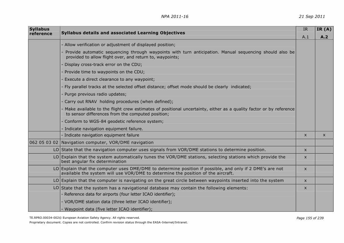
NPA 2011-16 21 Sep 2011
TE.RPRO.00034-002© European Aviation Safety Agency. All rights reserved.
Proprietary document. Copies are not controlled. Confirm revision status through the EASA-Internet/Intranet.
Page 155 of 239
Syllabus reference Syllabus details and associated Learning Objectives
IR
A.1
IR (A)
A.2
- Allow verification or adjustment of displayed position;
- Provide automatic sequencing through waypoints with turn anticipation. Manual sequencing should also be
provided to allow flight over, and return to, waypoints;
- Display cross-track error on the CDU;
- Provide time to waypoints on the CDU;
- Execute a direct clearance to any waypoint;
- Fly parallel tracks at the selected offset distance; offset mode should be clearly indicated;
- Purge previous radio updates;
- Carry out RNAV holding procedures (when defined);
- Make available to the flight crew estimates of positional uncertainty, either as a quality factor or by reference
to sensor differences from the computed position;
- Conform to WGS-84 geodetic reference system;
- Indicate navigation equipment failure.
- Indicate navigation equipment failure x x
062 05 03 02 Navigation computer, VOR/DME navigation
LO State that the navigation computer uses signals from VOR/DME stations to determine position. x
LO Explain that the system automatically tunes the VOR/DME stations, selecting stations which provide the best angular fix determination
x
LO Explain that the computer uses DME/DME to determine position if possible, and only if 2 DME’s are not available the system will use VOR/DME to determine the position of the aircraft.
x
LO Explain that the computer is navigating on the great circle between waypoints inserted into the system x
LO State that the system has a navigational database may contain the following elements:
- Reference data for airports (four letter ICAO identifier);
- VOR/DME station data (three letter ICAO identifier);
- Waypoint data (five letter ICAO identifier);
x

NPA 2011-16 21 Sep 2011
TE.RPRO.00034-002© European Aviation Safety Agency. All rights reserved.
Proprietary document. Copies are not controlled. Confirm revision status through the EASA-Internet/Intranet.
Page 156 of 239
Syllabus reference Syllabus details and associated Learning Objectives
IR
A.1
IR (A)
A.2
- STAR data;
- SID data;
- Airport runway data including thresholds and outer makers;
- NDB stations (alphabetic ICAO identifier); - Company flight plan routes.
LO State that the navigational database is valid for a limited time, usually 28 days. x
LO State that the navigational database is read only, but additional space exists so that crew created navigational data may be saved in the computer memory. Such additional data will also be deleted at the 28 days navigational update of the database.
x
LO State that the computer receives a TAS input from the air data computer, and a heading input in order to calculate actual wind velocity.
x
LO State that the computer calculates track error in relation to desired track. This data can easily be interfaced with the automatic flight control, and when done so enables the aircraft to automatically follow the flight plan loaded into the RNAV computer.
x
LO State that the computer is able to perform great circle navigation when receiving VOR/DME stations. If out of range, the system reverts to DR (dead reckoning) mode, where it updates the position by means of last computed wind and TAS and heading information. Operation in DR mode is time limited.
x
LO State that the system has ”direct to” capability to any waypoint. x
LO State that the system is capable of parallel off-set tracking. x
LO State that any waypoint can be inserted into the computer in one of the following ways:
- Alphanumeric ICAO identifier
- Latitude and longitude - Radial and distance from a VOR station
x
062 05 03 03 Navigation computer input/output
LO State that the following are input data into a 4D RNAV system:
- DME distances from DME stations
x
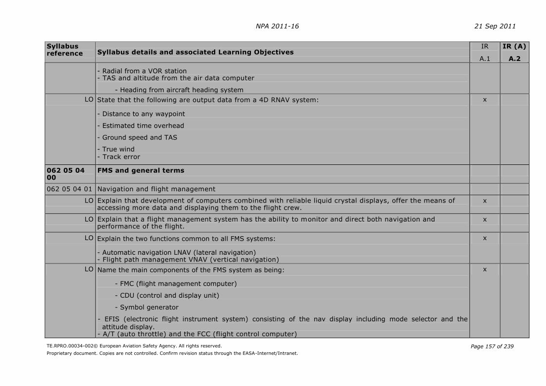
NPA 2011-16 21 Sep 2011
TE.RPRO.00034-002© European Aviation Safety Agency. All rights reserved.
Proprietary document. Copies are not controlled. Confirm revision status through the EASA-Internet/Intranet.
Page 157 of 239
Syllabus reference Syllabus details and associated Learning Objectives
IR
A.1
IR (A)
A.2
- Radial from a VOR station - TAS and altitude from the air data computer
- Heading from aircraft heading system
LO State that the following are output data from a 4D RNAV system:
- Distance to any waypoint
- Estimated time overhead
- Ground speed and TAS
- True wind - Track error
x
062 05 04 00
FMS and general terms
062 05 04 01 Navigation and flight management
LO Explain that development of computers combined with reliable liquid crystal displays, offer the means of accessing more data and displaying them to the flight crew.
x
LO Explain that a flight management system has the ability to monitor and direct both navigation and performance of the flight.
x
LO Explain the two functions common to all FMS systems:
- Automatic navigation LNAV (lateral navigation) - Flight path management VNAV (vertical navigation)
x
LO Name the main components of the FMS system as being:
- FMC (flight management computer)
- CDU (control and display unit)
- Symbol generator
- EFIS (electronic flight instrument system) consisting of the nav display including mode selector and the
attitude display. - A/T (auto throttle) and the FCC (flight control computer)
x

NPA 2011-16 21 Sep 2011
TE.RPRO.00034-002© European Aviation Safety Agency. All rights reserved.
Proprietary document. Copies are not controlled. Confirm revision status through the EASA-Internet/Intranet.
Page 158 of 239
Syllabus reference Syllabus details and associated Learning Objectives
IR
A.1
IR (A)
A.2
062 05 04 02 Flight management computer
LO State that the centre of the flight management system is the FMC with its stored navigation and performance data.
x
062 05 04 03 Navigation data base
LO State that the navigation database of the FMC may contain the following data:
- Reference data for airports (four letter ICAO identifier)
- VOR/DME station data (three letter ICAO identifier)
- Waypoint data (five letter ICAO identifier)
- STAR data
- SID data
- Holding patterns
- Airport runway data
- NDB stations (alphabetic ICAO identifier)
- Company flight plan routes
x x
LO State that the navigation database is updated every 28 days. x x
LO State that the navigational database is write protected, but additional space exists so that crew created navigational data may be saved in the computer memory. Such additional data will also be deleted at the 28 days navigational update of the database.
x x
062 05 04 04 Performance data base
LO State that the performance database stores all the data relating to the specific aircraft/engine configuration, and is updated by ground staff when necessary.
x
LO State that the performance database of the FMC contain the following data:
- V1, VR and V2 speeds
- Aircraft drag
- Engine thrust characteristics
x

NPA 2011-16 21 Sep 2011
TE.RPRO.00034-002© European Aviation Safety Agency. All rights reserved.
Proprietary document. Copies are not controlled. Confirm revision status through the EASA-Internet/Intranet.
Page 159 of 239
Syllabus reference Syllabus details and associated Learning Objectives
IR
A.1
IR (A)
A.2
- Maximum and optimum operating altitudes
- Speeds for maximum and optimum climb
- Speeds for long range cruise, max endurance and holding
- Maximum ZFM (zero fuel mass), maximum TOM (take-off mass) and maximum LM (landing mass)
- Fuel flow parameters
- Aircraft flight envelope
062 05 04 05 Typical input/output data from the FMC
LO State the following are typical input data to the FMC:
- Time
- Fuel flow
- Total fuel
- TAS, altitude, vertical speed, Mach number and outside air temperature from the air data computer (ADC)
- DME and radial information from the VHF NAV receivers
- Air/ground position
- Flap/slat position
- IRS and GPS positions
- CDU (control and display unit) entries
x
LO State that the following are typical output data from the FMC:
- Command signals to the flight directors and autopilot
- Command signals to the auto-throttle
- Information to the EFIS displays through the symbol generator - Data to the CDU and various annunciators
x
062 05 04 06 Determination of the FMS-position of the aircraft
LO State that modern FMS may use a range of sensors for calculating the position of the aircraft including x x
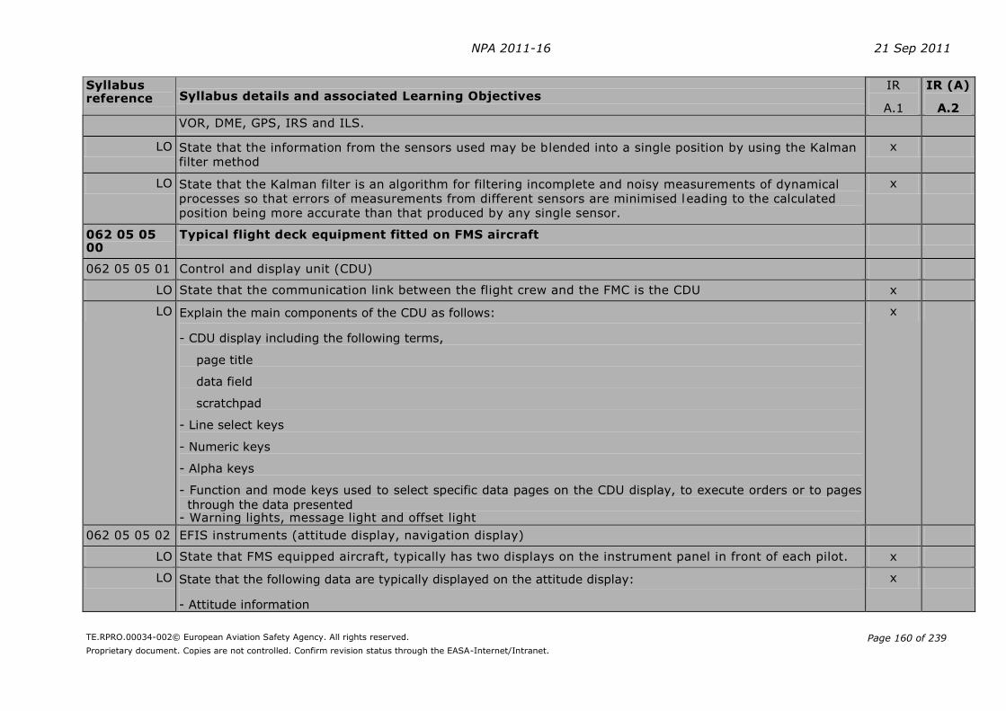
NPA 2011-16 21 Sep 2011
TE.RPRO.00034-002© European Aviation Safety Agency. All rights reserved.
Proprietary document. Copies are not controlled. Confirm revision status through the EASA-Internet/Intranet.
Page 160 of 239
Syllabus reference Syllabus details and associated Learning Objectives
IR
A.1
IR (A)
A.2
VOR, DME, GPS, IRS and ILS.
LO State that the information from the sensors used may be blended into a single position by using the Kalman filter method
x
LO State that the Kalman filter is an algorithm for filtering incomplete and noisy measurements of dynamical processes so that errors of measurements from different sensors are minimised leading to the calculated position being more accurate than that produced by any single sensor.
x
062 05 05 00
Typical flight deck equipment fitted on FMS aircraft
062 05 05 01 Control and display unit (CDU)
LO State that the communication link between the flight crew and the FMC is the CDU x
LO Explain the main components of the CDU as follows:
- CDU display including the following terms,
page title
data field
scratchpad
- Line select keys
- Numeric keys
- Alpha keys
- Function and mode keys used to select specific data pages on the CDU display, to execute orders or to pages
through the data presented - Warning lights, message light and offset light
x
062 05 05 02 EFIS instruments (attitude display, navigation display)
LO State that FMS equipped aircraft, typically has two displays on the instrument panel in front of each pilot. x
LO State that the following data are typically displayed on the attitude display:
- Attitude information
x

NPA 2011-16 21 Sep 2011
TE.RPRO.00034-002© European Aviation Safety Agency. All rights reserved.
Proprietary document. Copies are not controlled. Confirm revision status through the EASA-Internet/Intranet.
Page 161 of 239
Syllabus reference Syllabus details and associated Learning Objectives
IR
A.1
IR (A)
A.2
- Flight director command bars
- Radio height and barometric altitude
- Course deviation indication
- Glide path information (when an ILS is tuned) - Speed information
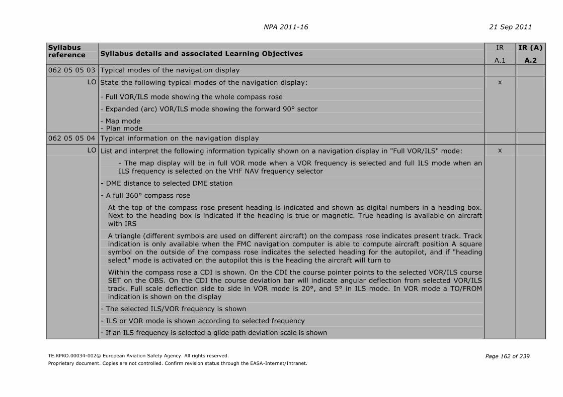
NPA 2011-16 21 Sep 2011
TE.RPRO.00034-002© European Aviation Safety Agency. All rights reserved.
Proprietary document. Copies are not controlled. Confirm revision status through the EASA-Internet/Intranet.
Page 162 of 239
Syllabus reference Syllabus details and associated Learning Objectives
IR
A.1
IR (A)
A.2
062 05 05 03 Typical modes of the navigation display
LO State the following typical modes of the navigation display:
- Full VOR/ILS mode showing the whole compass rose
- Expanded (arc) VOR/ILS mode showing the forward 90° sector
- Map mode - Plan mode
x
062 05 05 04 Typical information on the navigation display
LO List and interpret the following information typically shown on a navigation display in "Full VOR/ILS" mode:
- The map display will be in full VOR mode when a VOR frequency is selected and full ILS mode when an
ILS frequency is selected on the VHF NAV frequency selector
- DME distance to selected DME station
- A full 360° compass rose
At the top of the compass rose present heading is indicated and shown as digital numbers in a heading box.
Next to the heading box is indicated if the heading is true or magnetic. True heading is available on aircraft
with IRS
A triangle (different symbols are used on different aircraft) on the compass rose indicates present track. Track
indication is only available when the FMC navigation computer is able to compute aircraft position A square
symbol on the outside of the compass rose indicates the selected heading for the autopilot, and if "heading
select" mode is activated on the autopilot this is the heading the aircraft will turn to
Within the compass rose a CDI is shown. On the CDI the course pointer points to the selected VOR/ILS course
SET on the OBS. On the CDI the course deviation bar will indicate angular deflection from selected VOR/ILS
track. Full scale deflection side to side in VOR mode is 20°, and 5° in ILS mode. In VOR mode a TO/FROM
indication is shown on the display
- The selected ILS/VOR frequency is shown
- ILS or VOR mode is shown according to selected frequency
- If an ILS frequency is selected a glide path deviation scale is shown
x

NPA 2011-16 21 Sep 2011
TE.RPRO.00034-002© European Aviation Safety Agency. All rights reserved.
Proprietary document. Copies are not controlled. Confirm revision status through the EASA-Internet/Intranet.
Page 163 of 239
Syllabus reference Syllabus details and associated Learning Objectives
IR
A.1
IR (A)
A.2
LO A wind arrow indicating wind direction according to the compass rose, and velocity in numbers next to the
arrow
x
LO Given an EFIS navigation display in full VOR/ILS mode, read off the following information:
- Heading (Magnetic/True)
- Track (Magnetic/True)
- Drift
- Wind correction angle
- Selected course
- Actual radial
- Left or right of selected track
- Above or below the glide path
- Distance to the DME station
- Selected heading for the autopilot heading select bug
- Determine if the display is in VOR or ILS rose mode
x
LO Given an EFIS navigation display in expanded VOR/ILS mode, read off the following information:
- Heading (Magnetic/True)
- Track (Magnetic/True)
- Drift
- Wind correction angle
- Tailwind/headwind
- Wind velocity
- Selected course
- Actual radial
x

NPA 2011-16 21 Sep 2011
TE.RPRO.00034-002© European Aviation Safety Agency. All rights reserved.
Proprietary document. Copies are not controlled. Confirm revision status through the EASA-Internet/Intranet.
Page 164 of 239
Syllabus reference Syllabus details and associated Learning Objectives
IR
A.1
IR (A)
A.2
- Left or right of selected track
- Above or below the glide path
- Distance to the DME station - Selected heading for the autopilot heading select bug - State if the display is in VOR or ILS rose mode
LO Given an EFIS navigation display in map mode, read off the following information:
- Heading (Magnetic/True)
- Track (Magnetic/True)
- Drift
- Wind correction angle
- Tailwind/headwind
- Wind velocity
- Left or right of the FMS track
- Distance to active waypoint;
- ETO next waypoint
- Selected heading for the autopilot heading select bug
- Determine if a depicted symbol is a VOR/DME station or an airport
- Determine if a specific waypoint is part of the FMS route
x
LO Given an EFIS navigation display in plan mode, read off the following information:
- Heading (Magnetic/True)
- Track (Magnetic/True)
- Drift
- Wind correction angle
- Distance to active waypoint
x

NPA 2011-16 21 Sep 2011
TE.RPRO.00034-002© European Aviation Safety Agency. All rights reserved.
Proprietary document. Copies are not controlled. Confirm revision status through the EASA-Internet/Intranet.
Page 165 of 239
Syllabus reference Syllabus details and associated Learning Objectives
IR
A.1
IR (A)
A.2
- ETO active waypoint
- State selected heading for the autopilot heading select bug
- Measure and state true track of specific FMS route track
062 06 00 00
GLOBAL NAVIGATION SATELLITE SYSTEMS
062 06 01 00
GPS/GLONASS/GALILEO
062 06 01 01 Principles
LO State that there are two main Global Navigation Satellite Systems (GNSS) currently in existence with a third which is planned to be fully operational by 2011. They are:
- USA NAVSTAR GPS (NAVigation System with Timing And Ranging Global Positioning System - Russian GLONASS (GLObal NAvigation Satellite System) - European GALILEO
x x
LO State that all 3 systems (will) consist of a constellation of satellites which can be used by a suitably equipped receiver to determine position
x x
062 06 01 02 Operation
NAVSTAR GPS
LO State that there are currently two modes of operation, SPS (Standard Positioning Service) for civilian users, and PPS (Precise Positioning Service for authorised users
x x
LO SPS was originally designed to provide civil users with a less accurate positioning capability than PPS x x
LO Name the three segments as:
- Space segment - Control segment - User segment
x x
Space segment
LO State that the space segment consists of a notional constellation of 24 operational satellites x x
LO State that the satellites are orbiting the earth in orbits inclined 55° to the plane of the equator x
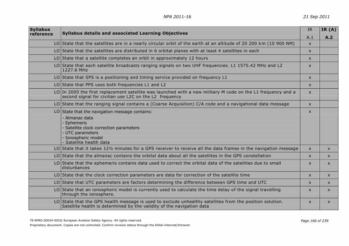
NPA 2011-16 21 Sep 2011
TE.RPRO.00034-002© European Aviation Safety Agency. All rights reserved.
Proprietary document. Copies are not controlled. Confirm revision status through the EASA-Internet/Intranet.
Page 166 of 239
Syllabus reference Syllabus details and associated Learning Objectives
IR
A.1
IR (A)
A.2
LO State that the satellites are in a nearly circular orbit of the earth at an altitude of 20 200 km (10 900 NM) x
LO State that the satellites are distributed in 6 orbital planes with at least 4 satellites in each x
LO State that a satellite completes an orbit in approximately 12 hours x
LO State that each satellite broadcasts ranging signals on two UHF frequencies. L1 1575.42 MHz and L2 1227.6 MHz
x
LO State that SPS is a positioning and timing service provided on frequency L1 x
LO State that PPS uses both frequencies L1 and L2 x
LO In 2005 the first replacement satellite was launched with a new military M code on the L1 frequency and a second signal for civilian use L2C on the L2 frequency
x
LO State that the ranging signal contains a (Coarse Acquisition) C/A code and a navigational data message x
LO State that the navigation message contains:
- Almanac data - Ephemeris - Satellite clock correction parameters - UTC parameters - Ionospheric model - Satellite health data
x
LO State that it takes 12½ minutes for a GPS receiver to receive all the data frames in the navigation message x x
LO State that the almanac contains the orbital data about all the satellites in the GPS constellation x x
LO State that the ephemeris contains data used to correct the orbital data of the satellites due to small disturbances
x x
LO State that the clock correction parameters are data for correction of the satellite time x x
LO State that UTC parameters are factors determining the difference between GPS time and UTC x x
LO State that an ionospheric model is currently used to calculate the time delay of the signal travelling through the ionosphere.
x x
LO State that the GPS health message is used to exclude unhealthy satellites from the position solution. Satellite health is determined by the validity of the navigation data
x x

NPA 2011-16 21 Sep 2011
TE.RPRO.00034-002© European Aviation Safety Agency. All rights reserved.
Proprietary document. Copies are not controlled. Confirm revision status through the EASA-Internet/Intranet.
Page 167 of 239
Syllabus reference Syllabus details and associated Learning Objectives
IR
A.1
IR (A)
A.2
LO State that GPS uses the WGS 84 model x x
LO State that two codes are transmitted on the L1 frequency, namely a C/A code and a P (precision) code. The P code is not used for SPS
x
LO State that the C/A code is a pseudo random noise (PRN) code sequence, repeating every mil lisecond. Each C/A code is unique and provides the mechanism to identify each satellite
x
LO State that satellites broadcast the PRN codes with reference to the satellite vehicle time which are subsequently changed by the receiver to UTC
x
LO State that satellites are equipped with atomic clocks, which allow the system to keep very accurate time reference
x x
Control Segment
LO State that the control segment comprises:
- A master control station - Ground antenna - Monitoring stations
x x
LO State that the master control station is responsible for all aspects of the constellation command and control x
LO State that the main tasks of the control segment are:
- Managing SPS performance - Navigation data upload - Monitoring satellites
x
User Segment
LO State that GPS supplies three-dimensional position fixes and speed data, plus a precise time reference x x
LO State that the GPS receiver used in aviation is a multi-channel type x x
LO State that a GPS receiver is able to determine the distance to a satellite, by determining the difference between the time of transmission by satellite and the time of reception
x x
LO State that the initial distance calculated to the satellites is called pseudo range because the difference between the GPS receiver and the satellite time references initially creates an erroneous range
x x
LO State that each range defines a sphere with its centre at the satellite x x
LO State that three satellites are needed to determine a two-dimensional position x x
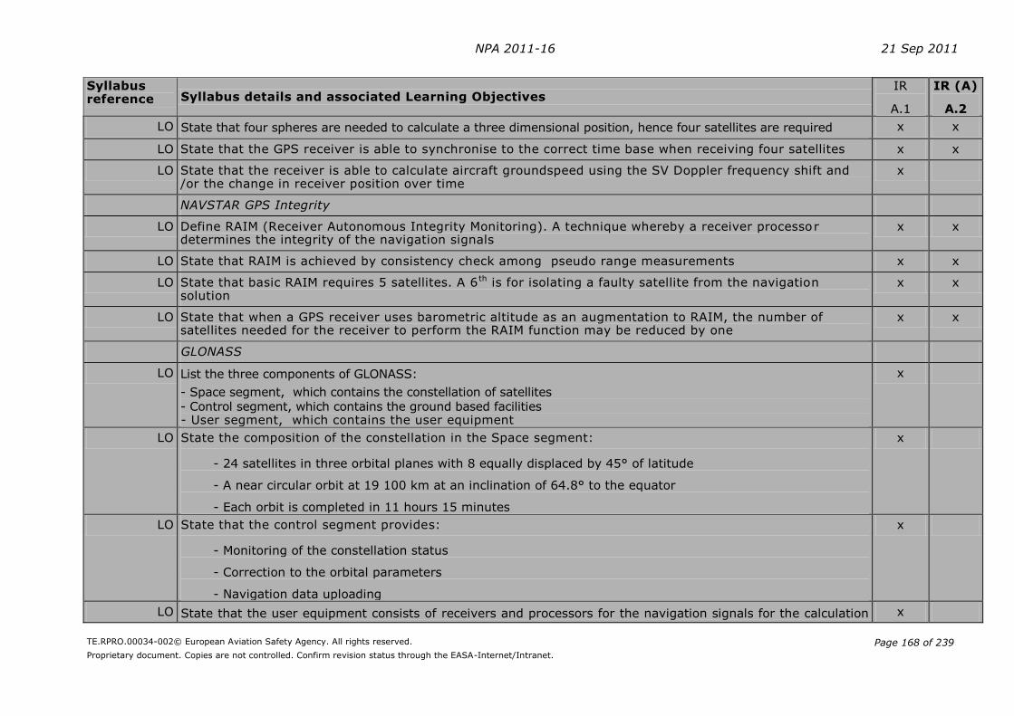
NPA 2011-16 21 Sep 2011
TE.RPRO.00034-002© European Aviation Safety Agency. All rights reserved.
Proprietary document. Copies are not controlled. Confirm revision status through the EASA-Internet/Intranet.
Page 168 of 239
Syllabus reference Syllabus details and associated Learning Objectives
IR
A.1
IR (A)
A.2
LO State that four spheres are needed to calculate a three dimensional position, hence four satellites are required x x
LO State that the GPS receiver is able to synchronise to the correct time base when receiving four satellites x x
LO State that the receiver is able to calculate aircraft groundspeed using the SV Doppler frequency shift and /or the change in receiver position over time
x
NAVSTAR GPS Integrity
LO Define RAIM (Receiver Autonomous Integrity Monitoring). A technique whereby a receiver processor determines the integrity of the navigation signals
x x
LO State that RAIM is achieved by consistency check among pseudo range measurements x x
LO State that basic RAIM requires 5 satellites. A 6th is for isolating a faulty satellite from the navigation solution
x x
LO State that when a GPS receiver uses barometric altitude as an augmentation to RAIM, the number of satellites needed for the receiver to perform the RAIM function may be reduced by one
x x
GLONASS
LO List the three components of GLONASS:
- Space segment, which contains the constellation of satellites - Control segment, which contains the ground based facilities - User segment, which contains the user equipment
x
LO State the composition of the constellation in the Space segment:
- 24 satellites in three orbital planes with 8 equally displaced by 45° of latitude
- A near circular orbit at 19 100 km at an inclination of 64.8° to the equator
- Each orbit is completed in 11 hours 15 minutes
x
LO State that the control segment provides:
- Monitoring of the constellation status
- Correction to the orbital parameters
- Navigation data uploading
x
LO State that the user equipment consists of receivers and processors for the navigation signals for the calculation x
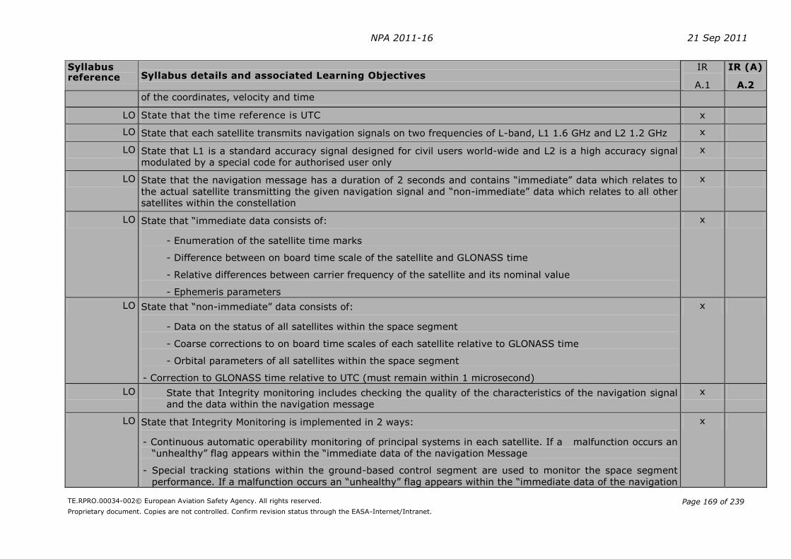
NPA 2011-16 21 Sep 2011
TE.RPRO.00034-002© European Aviation Safety Agency. All rights reserved.
Proprietary document. Copies are not controlled. Confirm revision status through the EASA-Internet/Intranet.
Page 169 of 239
Syllabus reference Syllabus details and associated Learning Objectives
IR
A.1
IR (A)
A.2
of the coordinates, velocity and time
LO State that the time reference is UTC x
LO State that each satellite transmits navigation signals on two frequencies of L-band, L1 1.6 GHz and L2 1.2 GHz x
LO State that L1 is a standard accuracy signal designed for civil users world-wide and L2 is a high accuracy signal
modulated by a special code for authorised user only
x
LO State that the navigation message has a duration of 2 seconds and contains “immediate” data which relates to
the actual satellite transmitting the given navigation signal and “non-immediate” data which relates to all other
satellites within the constellation
x
LO State that “immediate data consists of:
- Enumeration of the satellite time marks
- Difference between on board time scale of the satellite and GLONASS time
- Relative differences between carrier frequency of the satellite and its nominal value
- Ephemeris parameters
x
LO State that “non-immediate” data consists of:
- Data on the status of all satellites within the space segment
- Coarse corrections to on board time scales of each satellite relative to GLONASS time
- Orbital parameters of all satellites within the space segment
- Correction to GLONASS time relative to UTC (must remain within 1 microsecond)
x
LO State that Integrity monitoring includes checking the quality of the characteristics of the navigation signal
and the data within the navigation message
x
LO State that Integrity Monitoring is implemented in 2 ways:
- Continuous automatic operability monitoring of principal systems in each satellite. If a malfunction occurs an
“unhealthy” flag appears within the “immediate data of the navigation Message
- Special tracking stations within the ground-based control segment are used to monitor the space segment
performance. If a malfunction occurs an “unhealthy” flag appears within the “immediate data of the navigation
x

NPA 2011-16 21 Sep 2011
TE.RPRO.00034-002© European Aviation Safety Agency. All rights reserved.
Proprietary document. Copies are not controlled. Confirm revision status through the EASA-Internet/Intranet.
Page 170 of 239
Syllabus reference Syllabus details and associated Learning Objectives
IR
A.1
IR (A)
A.2
Message
LO State that agreements have been made between the appropriate agencies for the interoperability by any
one approved user of NAVSTAR and GLONASS systems
x
GALILEO
LO State that the core of the Galileo constellation will consist of 30 satellites with nine plus a spare replacement in
each of three planes in near circular orbit at an altitude of 23 222 km inclined at 56° to the plane of the equator
x
LO State that the signals will be transmitted in three frequency bands 1164-1215 MHz, 1260-1300 MHz and 1559-
1591 MHz (1559-1591 MHz will be shared with GPS on a non-interference basis)
x
LO State that each orbit will take 14 hours x
LO State that each satellite has three sections, Timing, Signal generation and Transmit x
LO State that in the Timing section two clocks have been developed, a Rubidium Frequency Standard clock and a
more precise Passive Hydrogen Maser clock
x
LO State the Signal generation contains the navigation signals x
LO State that the navigation signals consist of a ranging code identifier and the navigation message x
LO State that the navigation message basically contains information concerning the satellite orbit (ephemeris) and
the clock references
x
LO State that the navigation message is “up-converted” on four navigation signal carriers and the outputs are
combined in a multiplexer before transmission in the Transmit section
x
LO State that the Navigation Antenna has been designed to minimise interference between satellites by having
equal power level propagation paths independent of elevation angle
x
LO State that the system is monitored in a similar way to both GPS NAVSTAR and GLONASS but also by a new
method based on spread-spectrum signals
x
LO State that the tracking, telemetry and command operations are controlled by sophisticated data encryption and
authentication procedures
x
LO GPS, EGNOS and GALILEO are compatible, will not interfere with each other, and the performance of the
receiver will be enhanced by interoperability of the systems
x
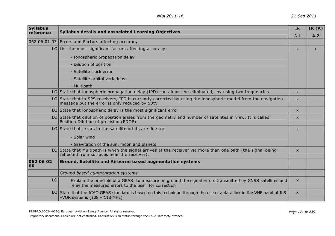
NPA 2011-16 21 Sep 2011
TE.RPRO.00034-002© European Aviation Safety Agency. All rights reserved.
Proprietary document. Copies are not controlled. Confirm revision status through the EASA-Internet/Intranet.
Page 171 of 239
Syllabus reference Syllabus details and associated Learning Objectives
IR
A.1
IR (A)
A.2
062 06 01 03 Errors and Factors affecting accuracy
LO List the most significant factors affecting accuracy:
- Ionospheric propagation delay
- Dilution of position
- Satellite clock error
- Satellite orbital variations
- Multipath
x x
LO State that ionospheric propagation delay (IPD) can almost be eliminated, by using two frequencies x
LO State that in SPS receivers, IPD is currently corrected by using the ionospheric model from the navigation message but the error is only reduced by 50%
x
LO State that ionospheric delay is the most significant error x
LO State that dilution of position arises from the geometry and number of satellites in view. It is called Position Dilution of precision (PDOP)
x
LO State that errors in the satellite orbits are due to:
- Solar wind
- Gravitation of the sun, moon and planets
x
LO State that Multipath is when the signal arrives at the receiver via more than one path (the signal being reflected from surfaces near the receiver).
x
062 06 02 00
Ground, Satellite and Airborne based augmentation systems
Ground based augmentation systems
LO Explain the principle of a GBAS: to measure on ground the signal errors transmitted by GNSS satellites and
relay the measured errors to the user for correction
x
LO State that the ICAO GBAS standard is based on this technique through the use of a data link in the VHF band of ILS –VOR systems (108 – 118 MHz)
x
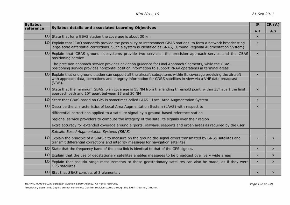
NPA 2011-16 21 Sep 2011
TE.RPRO.00034-002© European Aviation Safety Agency. All rights reserved.
Proprietary document. Copies are not controlled. Confirm revision status through the EASA-Internet/Intranet.
Page 172 of 239
Syllabus reference Syllabus details and associated Learning Objectives
IR
A.1
IR (A)
A.2
LO State that for a GBAS station the coverage is about 30 km x
LO Explain that ICAO standards provide the possibility to interconnect GBAS stations to form a network broadcasting large-scale differential corrections. Such a system is identified as GRAS, (Ground Regional Augmentation System)
x
LO Explain that GBAS ground subsystems provide two services: the precision approach service and the GBAS
positioning service
The precision approach service provides deviation guidance for Final Approach Segments, while the GBAS positioning service provides horizontal position information to support RNAV operations in terminal areas.
x
LO Explain that one ground station can support all the aircraft subsystems within its coverage providing the aircraft with approach data, corrections and integrity information for GNSS satellites in view via a VHF data broadcast (VDB).
x
LO State that the minimum GBAS plan coverage is 15 NM from the landing threshold point within 35° apart the final approach path and 10° apart between 15 and 20 NM
x
LO State that GBAS based on GPS is sometimes called LAAS : Local Area Augmentation System x
LO Describe the characteristics of Local Area Augmentation System (LAAS) with respect to:
differential corrections applied to a satellite signal by a ground-based reference station
regional service providers to compute the integrity of the satellite signals over their region
extra accuracy for extended coverage around airports, railways, seaports and urban areas as required by the user
x
Satellite Based Augmentation Systems (SBAS)
LO Explain the principle of a SBAS : to measure on the ground the signal errors transmitted by GNSS satellites and transmit differential corrections and integrity messages for navigation satellites
x x
LO State that the frequency band of the data link is identical to that of the GPS signals. x x
LO Explain that the use of geostationary satellites enables messages to be broadcast over very wide areas x x
LO Explain that pseudo-range measurements to these geostationary satellites can also be made, as if they were
GPS satellites
x x
LO Stat that SBAS consists of 3 elements : x x

NPA 2011-16 21 Sep 2011
TE.RPRO.00034-002© European Aviation Safety Agency. All rights reserved.
Proprietary document. Copies are not controlled. Confirm revision status through the EASA-Internet/Intranet.
Page 173 of 239
Syllabus reference Syllabus details and associated Learning Objectives
IR
A.1
IR (A)
A.2
- The ground infrastructure (monitoring and processing stations),
- The SBAS satellites,
- The SBAS airborne receivers.
LO Explain that SBAS station network measures the pseudo-range between the ranging source and an SBAS receiver at the known locations and provides separate corrections for ranging source ephemeris errors, clock errors and ionospheric errors. The user applies corrections for tropospheric delay.
x
LO Explain that SBAS can provide approach and landing operations with Vertical guidance (APV) and precision approach service .
x x
LO Explain the difference between Coverage area and Service area x x
LO State that Satellite Based Augmentation Systems include:
- EGNOS in Western Europe and the Mediterranean - WAAS in USA - MSAS in Japan - GAGAN in India
x x
LO Explain that SBAS systems regionally augment GPS and GLONASS by making them suitable for safety critical applications such as landing aircraft
x
EGNOS
LO State that (EGNOS) European Geostationary Navigation Overlay Service consists of 3 geostationary Inmarsat satellites which broadcast GPS look-alike signals
x x
LO State that EGNOS is designed to improve accuracy to 1-2 m horizontally and 3-5 m vertically x x
LO Explain that integrity and safety are improved by alerting users within 6 seconds if a GPS malfunction occurs (up to 3 hrs GPS alone)
x x
Airborne Based Augmentation Systems (ABAS)
LO Explain the principle of ABAS : to use redundant elements within the GPS constellation (e.g. : multiplicity of distance measurements to various satellites) or the combination of GNSS measurements with those of other navigation sensors (such as inertial systems), to develop integrity control
x x
LO State that the type of ABAS using only GNSS information is RAIM (Receiver Autonomous Integrity Monitoring) x x

NPA 2011-16 21 Sep 2011
TE.RPRO.00034-002© European Aviation Safety Agency. All rights reserved.
Proprietary document. Copies are not controlled. Confirm revision status through the EASA-Internet/Intranet.
Page 174 of 239
Syllabus reference Syllabus details and associated Learning Objectives
IR
A.1
IR (A)
A.2
LO State that a system using information from additional on-board sensors is named AAIM (Aircraft Autonomous Integrity Monitoring)
x x
LO Explain that the typical sensors used are barometric altimeter , clock and inertial navigation system x x
LO Explain that unlike GBAS and SBAS , ABAS does not improve positioning accuracy x x

NPA 2011-16 21 Sep 2011
TE.RPRO.00034-002© European Aviation Safety Agency. All rights reserved.
Proprietary document. Copies are not controlled. Confirm revision status through the EASA-Internet/Intranet.
Page 175 of 239
AMC7 FCL.615
DETAILED THEORETICAL KNOWLEDGE SYLLABUS AND LEARNING OBJECTIVES
Subject IFR Communications (Competency-based modular course according to Appendix 6 A.2)
Syllabus
reference Syllabus details and associated Learning Objectives IR
A.1
IR(A)
A.2
092 00 00 00 IFR COMMUNICATIONS
092 01 00 00 DEFINITIONS
092 01 01 00 Meanings and significance of associated terms
LO As for VFR plus terms used in conjunction with approach and holding procedures x x
092 01 02 00 Air Traffic Control abbreviations
LO As for VFR plus additional IFR related terms x x
092 01 03 00 Q-code groups commonly used in RTF air-ground communications
LO Define Q-code groups commonly used in RTF air to ground communications:
- Pressure settings
- Directions and bearings
x x
LO State the procedure for obtaining a bearing information in flight x x
092 01 04 00 Categories of messages
LO List the categories of messages in order of priority x x
LO Identify the types of messages appropriate to each category x x
LO List the priority of a message (given examples of messages to compare) x x
092 02 00 00 GENERAL OPERATING PROCEDURES
092 02 01 00 Transmission of letters
LO State the phonetic alphabet used in radiotelephony x x
LO Identify the occasions when words should be spelt x x
092 02 02 00 Transmission of numbers (including level information)

NPA 2011-16 21 Sep 2011
TE.RPRO.00034-002© European Aviation Safety Agency. All rights reserved.
Proprietary document. Copies are not controlled. Confirm revision status through the EASA-Internet/Intranet.
Page 176 of 239
Syllabus
reference Syllabus details and associated Learning Objectives IR
A.1
IR(A)
A.2
LO Describe the method of transmitting numbers
- Pronunciation
- Single digits, whole hundreds and whole thousands
x x
092 02 03 00 Transmission of time
LO Describe the ways of transmitting time
- Standard time reference (UTC)
- Minutes, minutes and hours, when required
x x
092 02 04 00 Transmission technique
LO Explain the techniques used for making good R/T transmissions x x
092 02 05 00 Standard words and phrases (relevant RTF phraseology included)
LO Define the meaning of standard words and phrases x x
LO Use correct standard phraseology for each phase of IFR flight
- Pushback
- IFR depature
- Airways clearances
- Position reporting
- Approach procedures
- IFR arrivals
x x
092 02 06 00 Radiotelephony call signs for aeronautical stations including use of abbreviated call signs
LO As for VFR x x
LO Name the two parts of the call sign of an aeronautical station x x
LO Identify the call sign suffixes for aeronautical stations x x
LO Explain when the call sign may be abbreviated to the use of suffix only x x
092 02 07 00 Radiotelephony call signs for aircraft including use of abbreviated call signs
LO As for VFR x x
LO Explain when the suffix “HEAVY” should be used with an aircraft call sign x x

NPA 2011-16 21 Sep 2011
TE.RPRO.00034-002© European Aviation Safety Agency. All rights reserved.
Proprietary document. Copies are not controlled. Confirm revision status through the EASA-Internet/Intranet.
Page 177 of 239
Syllabus
reference Syllabus details and associated Learning Objectives IR
A.1
IR(A)
A.2
LO Explain the use of the phrase “Change your call sign to . . .” x x
LO Explain the use of of the phrase “Revert to flight plan call sign” x x
092 02 08 00 Transfer of communication
LO Describe the procedure for transfer of communication
- By ground station
- By aircraft
x x
092 02 09 00 Test procedures including readability scale; establishment of RTF communication
LO Explain how to test radio transmission and reception x x
LO State the readability scale and explain its meaning x x
092 02 10 00 Read back and acknowledgement requirements
LO State the requirement to read back ATC route clearances x x
LO State the requirement to read back clearances related to runway in use x x
LO State the requirement to read back other clearances including conditional clearances x x
LO State the requirement to read back data such as runway, SSR codes etc x x
092 02 11 00 Radar procedural phraseology
LO Use the correct phraseology for an aircraft receiving a radar service
- Radar identification
- Radar vectoring
- Traffic information and avoidance
- SSR procedures
x x
092 02 12 00 Level changes and reports
LO Use the correct term to describe vertical position
- In relation to flight level (standard pressure setting)
- In relation to Altitude (metres/feet on QNH)
- In relation to Height (metres/feet on QFE)
x x
092 03 00 00 ACTION REQUIRED TO BE TAKEN IN CASE OF COMMUNICATION FAILURE
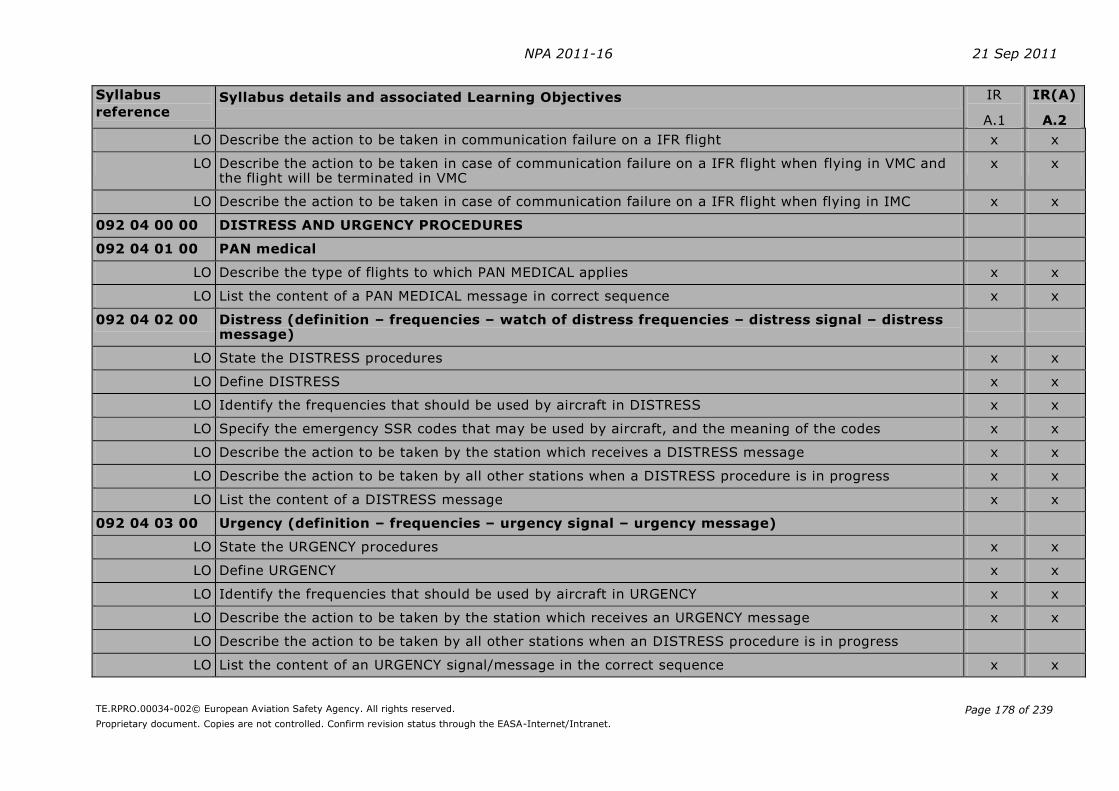
NPA 2011-16 21 Sep 2011
TE.RPRO.00034-002© European Aviation Safety Agency. All rights reserved.
Proprietary document. Copies are not controlled. Confirm revision status through the EASA-Internet/Intranet.
Page 178 of 239
Syllabus
reference Syllabus details and associated Learning Objectives IR
A.1
IR(A)
A.2
LO Describe the action to be taken in communication failure on a IFR flight x x
LO Describe the action to be taken in case of communication failure on a IFR flight when flying in VMC and the flight will be terminated in VMC
x x
LO Describe the action to be taken in case of communication failure on a IFR flight when flying in IMC x x
092 04 00 00 DISTRESS AND URGENCY PROCEDURES
092 04 01 00 PAN medical
LO Describe the type of flights to which PAN MEDICAL applies x x
LO List the content of a PAN MEDICAL message in correct sequence x x
092 04 02 00 Distress (definition – frequencies – watch of distress frequencies – distress signal – distress message)
LO State the DISTRESS procedures x x
LO Define DISTRESS x x
LO Identify the frequencies that should be used by aircraft in DISTRESS x x
LO Specify the emergency SSR codes that may be used by aircraft, and the meaning of the codes x x
LO Describe the action to be taken by the station which receives a DISTRESS message x x
LO Describe the action to be taken by all other stations when a DISTRESS procedure is in progress x x
LO List the content of a DISTRESS message x x
092 04 03 00 Urgency (definition – frequencies – urgency signal – urgency message)
LO State the URGENCY procedures x x
LO Define URGENCY x x
LO Identify the frequencies that should be used by aircraft in URGENCY x x
LO Describe the action to be taken by the station which receives an URGENCY message x x
LO Describe the action to be taken by all other stations when an DISTRESS procedure is in progress
LO List the content of an URGENCY signal/message in the correct sequence x x

NPA 2011-16 21 Sep 2011
TE.RPRO.00034-002© European Aviation Safety Agency. All rights reserved.
Proprietary document. Copies are not controlled. Confirm revision status through the EASA-Internet/Intranet.
Page 179 of 239
Syllabus
reference Syllabus details and associated Learning Objectives IR
A.1
IR(A)
A.2
092 05 00 00 RELEVANT WEATHER INFORMATION TERMS (IFR)
092 05 01 00 Aerodrome weather
LO As for VFR plus the following x x
LO Runway visual range x x
LO Braking action (friction coefficient) x x
092 05 02 00 Weather broadcast
LO As for VFR plus the following x x
LO Explain when aircraft routine meteorological observations should be made x x
LO Explain when aircraft Special meteorological observations should be made x x
092 06 00 00 GENERAL PRINCIPLES OF VHF PROPAGATION AND ALLOCATION OF FREQUENCIES
LO Describe the radio frequency spectrum with particular reference to VHF x x
LO State the names of the bands into which the radio frequency spectrum is divided x x
LO Identify the frequency range of the VHF band x x
LO Name the band normally used for Aeronautical Mobile Service voice communications x x
LO State the frequency separation allocated between consecutive VHF frequencies x x
LO Describe the propagation characteristics of radio transmissions in the VHF band x x
LO Describe the factors which reduce the effective range and quality of radio transmissions x x
LO State which of these factors apply to the VHF band x x
LO Calculate the effective range of VHF transmissions assuming no attenuating factors x x
092 07 00 00 MORSE CODE
LO Identify radio navigation aids (VOR, DME, NDB, ILS) from their morse code identifiers x x
LO SELCAL, TCAS, ACARS phraseology and procedures x x

NPA 2011-16 21 Sep 2011
TE.RPRO.00034-002© European Aviation Safety Agency. All rights reserved.
Proprietary document. Copies are not controlled. Confirm revision status through the EASA-Internet/Intranet.
Page 180 of 239
2) Subpart G – Instrument Rating – Section 1
A new GM1 FCL.615 is added:
GM1 FCL.615
DETAILED THEORETICAL KNOWLEDGE SYLLABUS AND LEARNING OBJECTIVES FOR THE ISSUE
OF AN INSTRUMENT RATING
The detailed theoretical knowledge syllabus is combined with the Learning Objectives (LOs).
The LOs refer to measurable statements of the skills and/or knowledge that a student should
be able to demonstrate following a defined element of training. The LOs define the theoretical
knowledge that a student should have assimilated on successful completion of an approved
theoretical knowledge course and/or prior to undertaking the theoretical knowledge
examinations.
The LOs are intended to be used by the training industry when developing Part-FCL theoretical
knowledge courses. It should be noted, however, that the LOs do not provide a ready-made
ground training syllabus for individual approved training organisations, and should not be seen
by organisations as a substitute for thorough course-design.
For the preparation of theoretical knowledge courses for the issue of instrument ratings, the
following information should be taken into account:
(a) Subject Air Law
(1) Subject Air Law is primarily based on ICAO documentation but will also refer to the
future European operational rules and the requirements dealing with pilot licensing.
(2) National Law should not be taken into account but remains relevant during practical
training and operational flying.
(3) Abbreviations used are ICAO abbreviations listed in ICAO Doc 8400, Abbreviations
and Codes.
(4) Where an LO refers to a definition e.g. ‘Define the following terms’ or ‘Define and
understand’ or ‘Explain the definitions in …’, candidates are also expected to be able
to recognise a given definition.
(b) Subject Flight Planning and Flight Monitoring
(1) To fully appreciate and understand the subject Flight Planning and Flight Monitoring,
the applicant will benefit from background knowledge in subjects Air Law, Aircraft
General Knowledge, Mass & Balance, Performance, Meteorology, Navigation,
Operational Procedures and Principles of Flight.
(2) The reference to the relevant requirements of the Regulation on Air Operations is
specifically mentioned in the LOs and should be used for reference as required.
(3) The Jeppesen Student Pilots’ Training Route Manual (SPTRM), otherwise known as
the Training Route Manual (TRM), contains planning data plus Aerodrome and
Approach charts that may be used in theoretical knowledge training courses.
3) Subpart G – Instrument Rating – Section 1
A new AMC1 to FCL.615 and FCL.825(d) is added:

NPA 2011-16 21 Sep 2011
TE.RPRO.00034-002© European Aviation Safety Agency. All rights reserved.
Proprietary document. Copies are not controlled. Confirm revision status through the EASA-Internet/Intranet.
Page 181 of 239
AMC1 FCL.615(b) and FCL.825(d) Instrument Rating and En-route Instrument Rating
Theoretical knowledge syllabus for the IR following the competency-based modular course (Appendix 6 A.2) and the EIR
1. The following tables contain the detailed theoretical knowledge syllabus for the IR following the competency-based modular route (IR(A)) and the EIR.
2. Aspects related to non-technical skills shall be included in an integrated manner, taking into account the particular risks associated to the licence and the activity.
010 00 00 00
AIR LAW
010 04 00 00 PERSONNEL LICENSING
010 05 00 00 RULES OF THE AIR
010 06 00 00 PROCEDURES FOR AIR NAVIGATION SERVICES – AIRCRAFT OPERATIONS
010 07 00 00 AIR TRAFFIC SERVICES AND AIR TRAFFIC MANAGEMENT
010 08 00 00 AERONAUTICAL INFORMATION SERVICE
010 09 00 00 AERODROMES
022 00 00 00 AIRCRAFT GENERAL KNOWLEDGE – INSTRUMENTATION
022 02 00 00 MEASUREMENT OF AIR DATA PARAMETERS
022 04 00 00 GYROSCOPIC INSTRUMENTS
022 13 00 00 INTEGRATED INSTRUMENTS – ELECTRONIC DISPLAYS
033 00 00 00 FLIGHT PLANNING AND FLIGHT MONITORING
033 02 00 00 FLIGHT PLANNING FOR IFR FLIGHTS
033 03 00 00 FUEL PLANNING
033 04 00 00 PRE-FLIGHT PREPARATION
033 05 00 00 ICAO FLIGHT PLAN (ATS FLIGHT PLAN)
040 00 00 00 HUMAN PERFORMANCE
040 01 00 00 HUMAN FACTORS: BASIC CONCEPTS
040 02 00 00 BASIC AVIATION PHYSIOLOGY AND HEALTH MAINTENANCE
040 03 00 00 BASIC AVIATION PSYCHOLOGY
050 00 00 00 METEOROLOGY
050 01 00 00 THE ATMOSPHERE
050 02 00 00 WIND
050 03 00 00 THERMODYNAMICS
050 04 00 00 CLOUDS AND FOG
050 05 00 00 PRECIPITATION
050 06 00 00 AIR MASSES AND FRONTS
050 07 00 00 PRESSURE SYSTEMS
050 08 00 00 CLIMATOLOGY
050 09 00 00 FLIGHT HAZARDS

NPA 2011-16 21 Sep 2011
TE.RPRO.00034-002© European Aviation Safety Agency. All rights reserved.
Proprietary document. Copies are not controlled. Confirm revision status through the EASA-Internet/Intranet.
Page 182 of 239
050 10 00 00 METEOROLOGICAL INFORMATION
062 00 00 00 RADIO NAVIGATION
062 02 00 00 RADIO AIDS
062 03 00 00 RADAR
062 05 00 00 AREA NAVIGATION SYSTEMS, RNAV/FMS
092 00 00 00 IFR COMMUNICATIONS
092 01 00 00 DEFINITIONS
092 02 00 00 GENERAL OPERATING PROCEDURES
092 03 00 00 ACTION REQUIRED TO BE TAKEN IN CASE OF COMMUNICATION FAILURE
092 04 00 00 DISTRESS AND URGENCY PROCEDURES
092 05 00 00 RELEVANT WEATHER INFORMATION TERMS (IFR)
092 06 00 00 GENERAL PRINCIPLES OF VHF PROPAGATION AND ALLOCATION OF FREQUENCIES
092 07 00 00 MORSE CODE
4) Subpart H – Class and type ratings – Section 2
Amend AMC1 FCL.720.A (b)(2)(i) as follows:
AMC1 to FCL.720.A (b)(2)(i)
Additional theoretical knowledge for a class or type rating for high performance single-pilot aeroplanes
1. A number of aeroplanes certificated for single pilot operation have similar performances, systems and navigation capabilities to those more usually associated with multi-pilot types of aeroplanes, and regularly operate within the same airspace. The level of knowledge required to operate safely in this environment is not part of, or not included to the necessary depth of knowledge in the training syllabi for the PPL, CPL or IR(A) but these licence holders may fly as pilot-in-command of such aeroplanes. The additional theoretical knowledge required to operate such aeroplanes safely is obtained by completion of an course at an approved training organisation.
2. The aim of the theoretical knowledge course is to provide the applicant with sufficient knowledge of those aspects of the operation of aeroplanes capable of operating at high speeds and altitudes, and the aircraft systems necessary for such operation.
COURSE SYLLABUS
3. The course will be divided in a VFR and an IFR part and should cover at least the following items of the aeroplane syllabus to the ATPL(A) level:
Subject Ref: Syllabus Content:
VFR Operation
021 00 00 00 AIRFRAME AND SYSTEMS, ELECTRICS, POWERPLANT
021 02 02 01
to
Alternating current - general
Generators

NPA 2011-16 21 Sep 2011
TE.RPRO.00034-002© European Aviation Safety Agency. All rights reserved.
Proprietary document. Copies are not controlled. Confirm revision status through the EASA-Internet/Intranet.
Page 183 of 239
021 02 02 03 AC power distribution
021 01 08 03 Pressurisation (Air driven systems - piston engines)
021 01 09 04 Pressurisation (Air driven systems - turbojet and turbo propeller)
021 03 01 06
021 03 01 07
021 03 01 08
021 03 01 09
Engine performance - piston engines
Power augmentation (turbo/supercharging)
Fuel
Mixture
021 03 02 00
to
021 03 04 09
Turbine engines
021 04 05 00 Aircraft oxygen equipment
032 02 00 00 PERFORMANCE CLASS B - ME AEROPLANES
032 02 01 00
to
032 02 04 01
Performance of multi-engine aeroplanes not certificated under JAR/FAR 25 –
Entire subject
040 02 00 00 HUMAN PERFORMANCE
040 02 01 00
to
040 02 01 03
Basic human physiology
and
High altitude environment
050 00 00 00 METEOROLOGY - WINDS AND FLIGHT HAZARDS
050 02 07 00
to
050 02 08 01
Jet streams
CAT
Standing waves
050 09 01 00
to
050 09 04 05
Flight hazards
Icing and turbulence
Thunderstorms
062 02 00 00 BASIC RADAR PRINCIPLES
062 02 01 00
to
062 02 05 00
Basic radar principles
Airborne radar
SSR
081 00 00 00 PRINCIPLES OF FLIGHT – AEROPLANES
081 02 01 00
to
081 02 03 02
Transonic aerodynamics - Entire subject
Mach number/shockwaves
buffet margin/aerodynamic ceiling
IFR Operation
010 06 07 00 Simultaneous Operation on parallel or near-parallel instrument Runways
010 06 08 00 Secondary surveillance radar (transponder) operating procedures
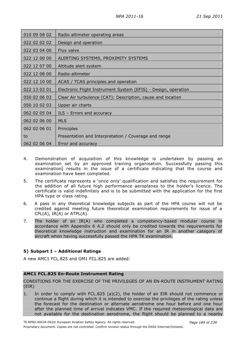
NPA 2011-16 21 Sep 2011
TE.RPRO.00034-002© European Aviation Safety Agency. All rights reserved.
Proprietary document. Copies are not controlled. Confirm revision status through the EASA-Internet/Intranet.
Page 184 of 239
010 09 08 02 Radio altimeter operating areas
022 02 02 02 Design and operation
022 03 04 00 Flux valve
022 12 00 00 ALERTING SYSTEMS, PROXIMITY SYSTEMS
022 12 07 00 Altitude alert system
022 12 08 00 Radio-altimeter
022 12 10 00 ACAS / TCAS principles and operation
022 13 03 01 Electronic Flight Instrument System (EFIS) - Design, operation
050 02 06 03 Clear Air turbulence (CAT): Description, cause and location
050 10 02 03 Upper air charts
062 02 05 04 ILS – Errors and accuracy
062 02 06 00 MLS
062 02 06 01
to
062 02 06 04
Principles
Presentation and Interpretation / Coverage and range
Error and accuracy
4. Demonstration of acquisition of this knowledge is undertaken by passing an examination set by an approved training organisation. Successfully passing this examination, results in the issue of a certificate indicating that the course and examination have been completed.
5. The certificate represents a ‘once only’ qualification and satisfies the requirement for the addition of all future high performance aeroplanes to the holder’s licence. The certificate is valid indefinitely and is to be submitted with the application for the first HPA type or class rating.
6. A pass in any theoretical knowledge subjects as part of the HPA course will not be
credited against meeting future theoretical examination requirements for issue of a
CPL(A), IR(A) or ATPL(A).
7. The holder of an IR(A) who completed a competency-based modular course in
accordance with Appendix 6 A.2 should only be credited towards the requirements for
theoretical knowledge instruction and examination for an IR in another category of
aircraft when having successfully passed the HPA TK examination.
5) Subpart I – Additional Ratings
A new AMC1 FCL.825 and GM1 FCL.825 are added:
AMC1 FCL.825 En-Route Instrument Rating
CONDITIONS FOR THE EXERCISE OF THE PRIVILEGES OF AN EN-ROUTE INSTRUMENT RATING
(EIR)
1. In order to comply with FCL.825 (a)(2), the holder of an EIR should not commence or
continue a flight during which it is intended to exercise the privileges of the rating unless
the forecast for the destination or alternate aerodrome one hour before and one hour
after the planned time of arrival indicates VMC. If the required meteorological data are
not available for the destination aerodrome, the flight should be planned to a nearby

NPA 2011-16 21 Sep 2011
TE.RPRO.00034-002© European Aviation Safety Agency. All rights reserved.
Proprietary document. Copies are not controlled. Confirm revision status through the EASA-Internet/Intranet.
Page 185 of 239
aerodrome for which such meteorological information is available. A VFR transition point
should be used in order to enable the pilot to conclude the flight under VFR to the
intended destination. For this purpose, when filing a flight plan in accordance with
operational rules, the holder of an EIR should include IFR/VFR transition points. If an IFR
approach procedure is established at the destination airfield, this IFR/VFR transition point
should be passed before reaching the Initial Approach Fix (IAF).
GM1 FCL.825 En-Route Instrument Rating
Since the privileges of the EIR are only to be exercised in the en-route phase of flight, the
holder of an EIR should:
1. at no time accept an IFR clearance to fly a departure, arrival or approach procedure;
2. declare an emergency to ATC if unable to complete a flight within the limitations of their
rating.
6) Subpart I – Additional Ratings
A new AMC2 FCL.825(c) is added:
AMC2 FCL.825(c) En-Route Instrument Rating
Flight Instruction
(a) FLIGHT INSTRUCTION
The flight instruction for the EIR within an ATO should comprise the following flying
exercises:
(1) pre-flight procedures for IFR flights, including the use of the flight manual,
meteorological information, appropriate air traffic service documents, filing of an IFR
flight plan, including VFR / IFR transitions and diversions;
(2) use of appropriate IFR and VFR charts;
(3) basic instrument flight by sole reference to instruments:
- horizontal flight,
- climbing,
- descending,
- turns in level flight, climbing, descending;
(4) steep turns and recovery from unusual attitudes on full and limited panel;
(5) normal flight on limited panel;
(6) instrument pattern;
(7) procedures and manoeuvres for IFR operation under normal, abnormal and
emergency conditions covering at least:
- transition from visual to instrument flight after departure,
- en-route IFR procedures,
- en-route holding procedures,
- transition from instrument flight en-route to visual before reaching the
Minimum Sector Altitude (MSA);
(8) radio navigation (GPS/VOR);
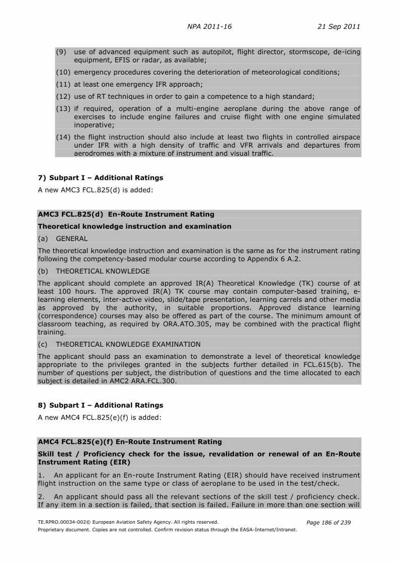
NPA 2011-16 21 Sep 2011
TE.RPRO.00034-002© European Aviation Safety Agency. All rights reserved.
Proprietary document. Copies are not controlled. Confirm revision status through the EASA-Internet/Intranet.
Page 186 of 239
(9) use of advanced equipment such as autopilot, flight director, stormscope, de-icing
equipment, EFIS or radar, as available;
(10) emergency procedures covering the deterioration of meteorological conditions;
(11) at least one emergency IFR approach;
(12) use of RT techniques in order to gain a competence to a high standard;
(13) if required, operation of a multi-engine aeroplane during the above range of
exercises to include engine failures and cruise flight with one engine simulated
inoperative;
(14) the flight instruction should also include at least two flights in controlled airspace
under IFR with a high density of traffic and VFR arrivals and departures from
aerodromes with a mixture of instrument and visual traffic.
7) Subpart I – Additional Ratings
A new AMC3 FCL.825(d) is added:
AMC3 FCL.825(d) En-Route Instrument Rating
Theoretical knowledge instruction and examination
(a) GENERAL
The theoretical knowledge instruction and examination is the same as for the instrument rating
following the competency-based modular course according to Appendix 6 A.2.
(b) THEORETICAL KNOWLEDGE
The applicant should complete an approved IR(A) Theoretical Knowledge (TK) course of at
least 100 hours. The approved IR(A) TK course may contain computer-based training, e-
learning elements, inter-active video, slide/tape presentation, learning carrels and other media
as approved by the authority, in suitable proportions. Approved distance learning
(correspondence) courses may also be offered as part of the course. The minimum amount of
classroom teaching, as required by ORA.ATO.305, may be combined with the practical flight
training.
(c) THEORETICAL KNOWLEDGE EXAMINATION
The applicant should pass an examination to demonstrate a level of theoretical knowledge
appropriate to the privileges granted in the subjects further detailed in FCL.615(b). The
number of questions per subject, the distribution of questions and the time allocated to each
subject is detailed in AMC2 ARA.FCL.300.
8) Subpart I – Additional Ratings
A new AMC4 FCL.825(e)(f) is added:
AMC4 FCL.825(e)(f) En-Route Instrument Rating
Skill test / Proficiency check for the issue, revalidation or renewal of an En-Route
Instrument Rating (EIR)
1. An applicant for an En-route Instrument Rating (EIR) should have received instrument
flight instruction on the same type or class of aeroplane to be used in the test/check.
2. An applicant should pass all the relevant sections of the skill test / proficiency check. If any item in a section is failed, that section is failed. Failure in more than one section will
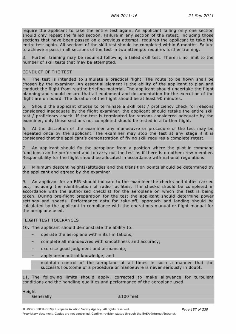
NPA 2011-16 21 Sep 2011
TE.RPRO.00034-002© European Aviation Safety Agency. All rights reserved.
Proprietary document. Copies are not controlled. Confirm revision status through the EASA-Internet/Intranet.
Page 187 of 239
require the applicant to take the entire test again. An applicant failing only one section should only repeat the failed section. Failure in any section of the retest, including those sections that have been passed on a previous attempt, requires the applicant to take the entire test again. All sections of the skill test should be completed within 6 months. Failure to achieve a pass in all sections of the test in two attempts requires further training.
3. Further training may be required following a failed skill test. There is no limit to the
number of skill tests that may be attempted.
CONDUCT OF THE TEST
4. The test is intended to simulate a practical flight. The route to be flown shall be
chosen by the examiner. An essential element is the ability of the applicant to plan and
conduct the flight from routine briefing material. The applicant should undertake the flight
planning and should ensure that all equipment and documentation for the execution of the
flight are on board. The duration of the flight should be at least 90 minutes.
5. Should the applicant choose to terminate a skill test / proficiency check for reasons considered inadequate by the flight examiner, the applicant should retake the entire skill test / proficiency check. If the test is terminated for reasons considered adequate by the examiner, only those sections not completed should be tested in a further flight.
6. At the discretion of the examiner any manoeuvre or procedure of the test may be
repeated once by the applicant. The examiner may stop the test at any stage if it is considered that the applicant’s demonstration of flying skill requires a complete retest.
7. An applicant should fly the aeroplane from a position where the pilot-in-command
functions can be performed and to carry out the test as if there is no other crew member.
Responsibility for the flight should be allocated in accordance with national regulations.
8. Minimum descent heights/altitudes and the transition points should be determined by
the applicant and agreed by the examiner.
9. An applicant for an EIR should indicate to the examiner the checks and duties carried
out, including the identification of radio facilities. The checks should be completed in
accordance with the authorised checklist for the aeroplane on which the test is being
taken. During pre-flight preparation for the test the applicant should determine power
settings and speeds. Performance data for take-off, approach and landing should be
calculated by the applicant in compliance with the operations manual or flight manual for
the aeroplane used.
FLIGHT TEST TOLERANCES
10. The applicant should demonstrate the ability to:
– operate the aeroplane within its limitations;
– complete all manoeuvres with smoothness and accuracy;
– exercise good judgment and airmanship;
– apply aeronautical knowledge; and
– maintain control of the aeroplane at all times in such a manner that the successful outcome of a procedure or manoeuvre is never seriously in doubt.
11. The following limits should apply, corrected to make allowance for turbulent
conditions and the handling qualities and performance of the aeroplane used
Height
Generally ±100 feet

NPA 2011-16 21 Sep 2011
TE.RPRO.00034-002© European Aviation Safety Agency. All rights reserved.
Proprietary document. Copies are not controlled. Confirm revision status through the EASA-Internet/Intranet.
Page 188 of 239
Tracking
on radio aids ±10°
Heading
all engines operating ±10°
with simulated engine failure ±15°
Speed
all engines operating +10 knots/-5 knots
with simulated engine failure +15 knots/–5 knots
CONTENT OF THE SKILL TEST / PROFICIENCY CHECK
SECTION 1
PRE-FLIGHT OPERATIONS AND DEPARTURE
Use of checklist, airmanship, anti/de-icing procedures, etc., apply in all sections.
a Use of flight manual (or equivalent) especially a/c performance calculation, mass
and balance
b Use of Air Traffic Services document, weather document
c Preparation of ATC flight plan, IFR flight plan/log
d Pre-flight inspection
e Weather Minima
f Taxiing
g Pre-take off briefing. Take-off
h ATC liaison - compliance, R/T procedures
SECTION 2
GENERAL HANDLING
a Control of the aeroplane by reference solely to instruments, including: level flight at
various speeds, trim
b Climbing and descending turns with sustained Rate 1 turn
c Recoveries from unusual attitudes, including sustained 45° bank turns and steep
descending turns
d Recovery from approach to stall in level flight, climbing/descending turns and in
landing configuration
e Limited panel, stabilised climb or descent at Rate 1 turn onto given headings,
recovery from unusual attitudes

NPA 2011-16 21 Sep 2011
TE.RPRO.00034-002© European Aviation Safety Agency. All rights reserved.
Proprietary document. Copies are not controlled. Confirm revision status through the EASA-Internet/Intranet.
Page 189 of 239
SECTION 3
EN-ROUTE IFR PROCEDURES
a Transition to instrument flight
b Tracking, including interception, e.g. NDB, VOR, RNAV
c Use of radio aids
d Level flight, control of heading, altitude and airspeed, power setting, trim technique
e Altimeter settings
f Timing and revision of ETAs (En-route hold – if required)
g Monitoring of flight progress, flight log, fuel usage, systems management
h Simulated emergency situation(s)
i Ice protection procedures, simulated if necessary
j Simulated diversion to alternate airfield
k Transition to visual flight
l ATC liaison and compliance, R/T procedures
SECTION 4
intentionally blank
SECTION 5
a Setting and checking of navigational aids, identification of facilities
b Arrival procedures, altimeter settings
c Approach and landing briefing, including descent/approach/landing checks
d Visual landing
e ATC liaison – compliance, R/T procedures
SECTION 6 (multi-engine aeroplanes only)
Flight with one engine inoperative
a Simulated engine failure during en-route phase of flight
b ATC liaison: compliance, R/T procedures
9) Subpart I – Additional Ratings

NPA 2011-16 21 Sep 2011
TE.RPRO.00034-002© European Aviation Safety Agency. All rights reserved.
Proprietary document. Copies are not controlled. Confirm revision status through the EASA-Internet/Intranet.
Page 190 of 239
A new AMC1 FCL.830 is added:
AMC1 FCL.830 Sailplane Cloud Flying Rating
Theoretical knowledge instruction and flight instruction
1. THEORETICAL KNOWLEDGE INSTRUCTION
The theoretical knowledge syllabus should cover the revision and/or explanation of:
1.1. Human Factors and Body Limitations
- basic aviation physiology in regards cloud flying aspects
- basic aviation psychology
- spatial disorientation
1.2. Principles of Flight
- stability
- control
- limitations (load factor and manoeuvres)
1.3. Aircraft Instrumentation
- sensors and instruments
- measurement of air data parameters
- gyroscopic instruments
1.4. Navigation
- use of GPS
- use of charts
- dead reckoning navigation (DR)
- air traffic regulations - airspace structure
- aeronautical information service
- Member State regulations regarding cloud flying
1.5. Communications
- VHF communications
- relevant weather information terms
1.6. Hazards and Emergency Procedures
- Icing
- Cloud escape procedures
- Anti-collision instruments/avionics
2. FLIGHT INSTRUCTION
2.1. The exercises of the sailplane cloud flight instruction syllabus should be repeated as
necessary until the student achieves a safe and competent standard and should
comprise at least the following practical training items, flown solely by reference to
instruments:
- straight flight
- turning
- achieving and maintaining heading
- return to straight flight from steeper angle of bank
- position fixing using GPS and aeronautical charts
- position estimating using DR
- basic cloud escape manoeuvre / unusual attitude

NPA 2011-16 21 Sep 2011
TE.RPRO.00034-002© European Aviation Safety Agency. All rights reserved.
Proprietary document. Copies are not controlled. Confirm revision status through the EASA-Internet/Intranet.
Page 191 of 239
- advanced cloud escape manoeuvre on nominated heading
2.2. At least one hour must be flown in a sailplane or powered sailplane (excluding TMG). The
remainder may be flown in a sailplane or powered sailplane (including TMG), or may be
credited in the case of pilots who hold, or have held an IR or EIR.
10) Subpart I – Additional Ratings
A new AMC2 FCL.830 is added:
AMC2 FCL.830 Sailplane Cloud Flying Rating
SKILL TEST AND PROFICIENCY CHECK
The skill test for the issue of the cloud flying rating or the proficiency check for the revalidation
or renewal should be conducted in either a sailplane or a powered sailplane and should contain
the following elements:
1. ORAL EXAMINATION
This part should be done before the flight and should cover all the relevant parts of the
theoretical knowledge syllabus. At least one question for each of the following sections
should be asked:
– Human performance and body limitations
– Principles of flight
– Aircraft instrumentation for cloud flying
– Navigation
– Communications
– Hazards and emergency procedures
If the oral examination reveals a lack in theoretical knowledge, the flight test should not
be done and the skill test is failed.
2. PRACTICAL SKILL TEST
During the practical skill test, the following limits should apply with appropriate allowance
for turbulent conditions and the handling qualities and performance of the sailplane used.
Artificial horizon or turn and slip instruments should be used as appropriate:
Artificial Horizon Turn & Slip
Straight flight Heading + 10o
IAS + 10kts
Heading + 20o
IAS + 20kts
Turning Angle of bank + 15o
IAS + 15kts
Rate of turn between ½ & full scale
IAS + 20kts
Position fixing given:
GPS displaying range and
bearing to a point
+ 2NM
+ 3NM
During the practical skill test, the following exercises should be successfully completed by
the applicant, flown solely by reference to instruments and taking into account the limits
above:

NPA 2011-16 21 Sep 2011
TE.RPRO.00034-002© European Aviation Safety Agency. All rights reserved.
Proprietary document. Copies are not controlled. Confirm revision status through the EASA-Internet/Intranet.
Page 192 of 239
- straight flight
- turning
- achieving and maintaining heading
- return to straight flight from steeper angle of bank
- position fixing using GPS and aeronautical charts
- position estimating using DR
- basic cloud escape manoeuvre / unusual attitude
- advanced cloud escape manoeuvre on nominated heading
11) AMC1 Appendix 6 Modular training courses for the IR
Amend AMC1 to Appendix 6 as follows:
AMC No 1 to Appendix 6
A.1. Modular training course for IR
1. The theoretical knowledge instruction may be given at an approved training organisation
conducting theoretical knowledge instruction only, in which case the Head of Training of that
organisation should supervise that part of the course.
2. The 150 hours of theoretical knowledge instruction can include classroom work, inter-active
video, slide/tape presentation, learning carrels, computer–based training, and other media as
approved by the authority, in suitable proportions. Approved distance learning
(correspondence) courses may also be offered as part of the course.
12) AMC2 Appendix 6 Modular training courses for the IR
A new AMC2 to Appendix 6 is added:
AMC2 Appendix 6
A.2. Competency-based training modular course for IR(A)
(a) THEORETICAL KNOWLEDGE INSTRUCTION
(1) The theoretical knowledge instruction may be given at an approved training
organisation conducting theoretical knowledge instruction only, in which case the
Head of Training of that organisation should supervise that part of the course.
(2) The required 100 hours of theoretical knowledge instruction for the IR following the
competency-based route may contain computer-based training, e-learning
elements, inter-active video, slide/tape presentation, learning carrels and other
media as approved by the authority, in suitable proportions. Approved distance
learning (correspondence) courses may also be offered as part of the course. The
minimum amount of classroom teaching has to be provided as required by
ORA.ATO.305.
(b) THEORETICAL KNOWLEDGE EXAMINATION
The applicant for the IR following the competency-based training route should pass an
examination to demonstrate a level of theoretical knowledge appropriate to the privileges
granted in the subjects further detailed in FCL.615(b). The number of questions per subject,
the distribution of questions and the time allocated to each subject is detailed in AMC2
ARA.FCL.300.

NPA 2011-16 21 Sep 2011
TE.RPRO.00034-002© European Aviation Safety Agency. All rights reserved.
Proprietary document. Copies are not controlled. Confirm revision status through the EASA-Internet/Intranet.
Page 193 of 239
Draft Commission Regulation laying down technical requirements and administrative
procedures related to civil aviation aircrew pursuant to Regulation (EC) No 216/2008
of the European Parliament and of the Council – Annex VI (Authority requirements
for aircrew - Part-ARA)
1) AMC2 ARA.FCL.300(b) Examination procedures
A new AMC2 to ARA.FCL.300(b) is added:
AMC2 ARA.FCL.300(b) Examination procedure
THEORETICAL KNOWLEGDE EXAMINATIONS FOR THE EN-ROUTE INSTRUMENT
RATING (EIR) AND THE INSTRUMENT RATING (IR)
The following tables contain the number of questions, the distribution of questions related to
the different syllabus topics and the time allowed for the theoretical knowledge examination.
The table on the right contains the necessary details for the theoretical examination of
applicants for the En-route Instrument Rating (EIR) and the IR(A) based on the competency-
based modular course according to Appendix 6 A.2. The table on the left contains the same
details for the IR(A) and (H) examination according to Appendix 6 A.1.
Subject: 010 - AIR LAW
Theoretical knowledge examination
Exam length and total questions
IR (A) & (H)
Appendix 6 A.1.
EIR & IR(A)
Appendix 6 A.2.
Time allowed 0:45 0:30
Distribution of questions with regard to the topics of the syllabus
010 01 xx xx
010 02 xx xx
010 03 xx xx
010 04 01 01
010 05 08 05
010 06 07 06
010 07 05 03
010 08 02 01
010 09 06 02
010 10 xx xx
010 11 xx xx
010 12 xx xx
010 13 xx xx
Total questions 33 18

NPA 2011-16 21 Sep 2011
TE.RPRO.00034-002© European Aviation Safety Agency. All rights reserved.
Proprietary document. Copies are not controlled. Confirm revision status through the EASA-Internet/Intranet.
Page 194 of 239
Subject: 022 - AIRCRAFT GENERAL KNOWLEDGE - INSTRUMENTATION
Theoretical knowledge examination
Exam length and total questions
IR(A) & (H)
Appendix 6 A.1.
EIR & IR(A)
Appendix 6 A.2.
Time allowed 0:30 0:20
Distribution of questions with regard to the topics of the syllabus
022 01 xx xx
022 02 06 05
022 03 04 xx
022 04 04 04
022 05 xx xx
022 06 xx xx
022 07 xx xx
022 08 xx xx
022 09 xx xx
022 10 xx xx
022 11 xx xx
022 12 03 xx
022 13 03 03
022 14 xx xx
022 15 xx xx
Total questions 20 12
Subject: 033 - FLIGHT PERFORMANCE AND PLANNING - FLIGHT PLANNING AND
MONITORING
Theoretical knowledge examination
Exam length and total questions
IR(A) & (H)
Appendix 6 A.1.
EIR & IR(A)
Appendix 6 A.2.
Time allowed 1:30 0:40
Distribution of questions with regard to the topics of the syllabus
033 01 xx xx
033 02 10 10
033 03 05 4
033 04 08 7
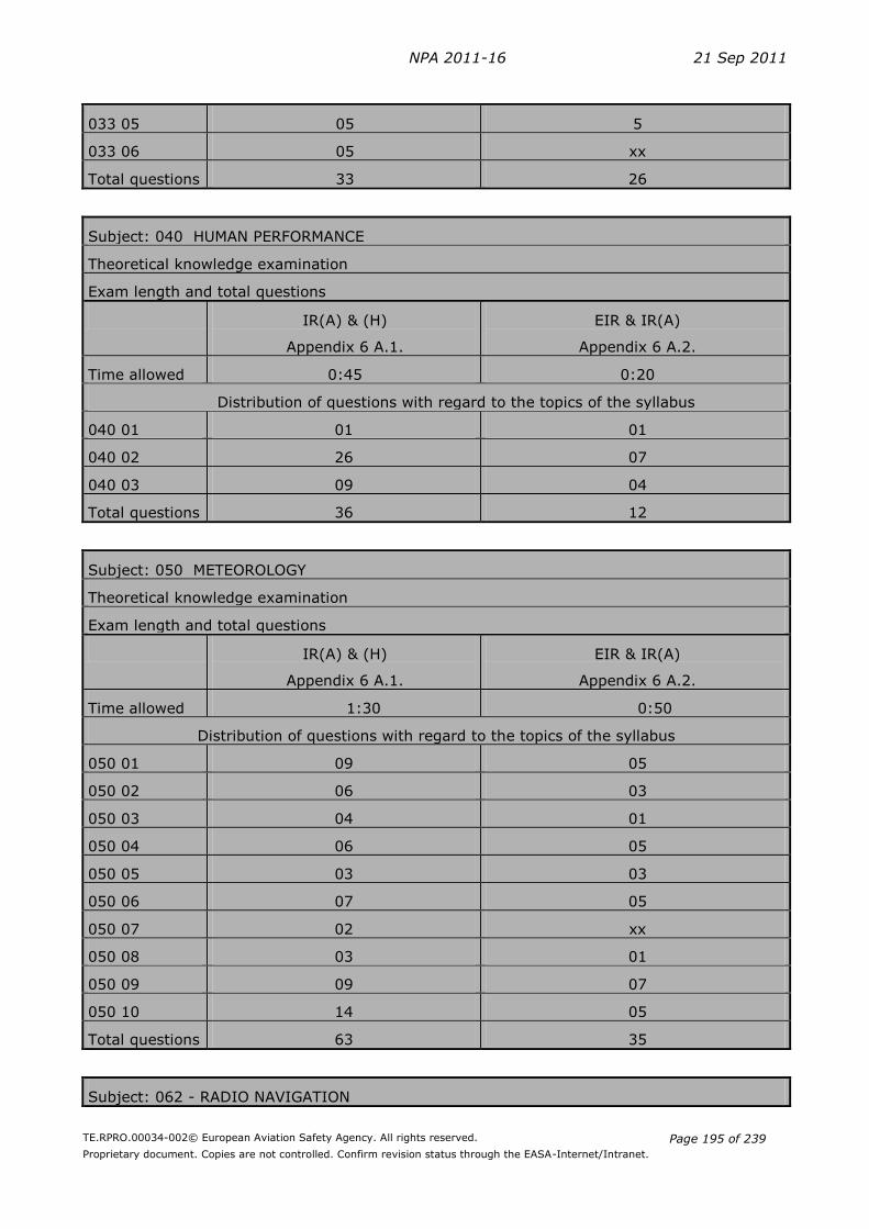
NPA 2011-16 21 Sep 2011
TE.RPRO.00034-002© European Aviation Safety Agency. All rights reserved.
Proprietary document. Copies are not controlled. Confirm revision status through the EASA-Internet/Intranet.
Page 195 of 239
033 05 05 5
033 06 05 xx
Total questions 33 26
Subject: 040 HUMAN PERFORMANCE
Theoretical knowledge examination
Exam length and total questions
IR(A) & (H)
Appendix 6 A.1.
EIR & IR(A)
Appendix 6 A.2.
Time allowed 0:45 0:20
Distribution of questions with regard to the topics of the syllabus
040 01 01 01
040 02 26 07
040 03 09 04
Total questions 36 12
Subject: 050 METEOROLOGY
Theoretical knowledge examination
Exam length and total questions
IR(A) & (H)
Appendix 6 A.1.
EIR & IR(A)
Appendix 6 A.2.
Time allowed 1:30 0:50
Distribution of questions with regard to the topics of the syllabus
050 01 09 05
050 02 06 03
050 03 04 01
050 04 06 05
050 05 03 03
050 06 07 05
050 07 02 xx
050 08 03 01
050 09 09 07
050 10 14 05
Total questions 63 35
Subject: 062 - RADIO NAVIGATION

NPA 2011-16 21 Sep 2011
TE.RPRO.00034-002© European Aviation Safety Agency. All rights reserved.
Proprietary document. Copies are not controlled. Confirm revision status through the EASA-Internet/Intranet.
Page 196 of 239
Theoretical knowledge examination
Exam length and total questions
IR(A) & (H)
Appendix 6 A.1.
EIR & IR(A)
Appendix 6 A.2.
Time allowed 1:00 0:40
Distribution of questions with regard to the topics of the syllabus
062 01 02 xx
062 02 23 15
062 03 05 03
062 04 xx xx
062 05 10 05
062 06 04 01
Total questions 44 24
Subject: 092 IFR COMMUNICATION
Theoretical knowledge examination
Exam length and total questions
IR(A)& (H)
Appendix 6 A.1.
EIR & IR(A)
Appendix 6 A.2.
Time allowed 0:30 0:30
Distribution of questions with regard to the topics of the syllabus
092 01 05 05
092 02 11 10
092 03 02 02
092 04 02 02
092 05 02 02
092 06 02 02
092 07 xx xx
Total questions 24 23
NPA 2011-16 21 Sep 2011
TE.RPRO.00034-002© European Aviation Safety Agency. All rights reserved.
Proprietary document. Copies are not controlled. Confirm revision status through the EASA-Internet/Intranet.
Page 197 of 239
C. Regulatory Impact Assessment
I. Regulatory Impact Assessment for the aeroplane instrument ratings
Table of Contents
1 PROCESS AND CONSULTATION ....................................................................... 198
2 ISSUE ANALYSIS AND RISK ASSESSMENT ....................................................... 198
2.1 WHAT IS THE ISSUE AND WHO IS AFFECTED? ............................................................ 198
2.2 COMPARISON OF FAA AND JAR-FCL REQUIREMENTS .................................................. 199
2.3 WHAT ARE THE RISKS (PROBABILITY AND SEVERITY)? .................................................. 202
3 OBJECTIVES .................................................................................................... 205
4 IDENTIFICATION OF OPTIONS ........................................................................ 205
5 METHODOLOGY AND DATA REQUIREMENTS .................................................... 207
5.1 APPLIED METHODOLOGY: MULTI-CRITERIA ANALYSIS ................................................... 207
5.2 DATA REQUIREMENTS ....................................................................................... 208
6 ANALYSIS OF IMPACTS ................................................................................... 210
6.1 SAFETY IMPACT ............................................................................................... 210
6.2 ENVIRONMENTAL IMPACT.................................................................................... 210
6.3 SOCIAL IMPACT............................................................................................... 211
6.4 ECONOMIC IMPACT ........................................................................................... 211
6.5 PROPORTIONALITY ISSUES .................................................................................. 215
6.6 IMPACT ON REGULATORY COORDINATION AND HARMONISATION ....................................... 215
7 CONCLUSION AND PREFERRED OPTION .......................................................... 216
7.1 COMPARING THE OPTIONS .................................................................................. 216
7.2 SENSITIVITY ANALYSIS ...................................................................................... 216
ANNEX 1: DATA ...................................................................................................... 217
ANNEX 2: GLOSSARY .............................................................................................. 222
ANNEX 3: REFERENCES ........................................................................................... 224
ANNEX 4: RISK ASSESSMENT ................................................................................. 225
NPA 2011-16 21 Sep 2011
TE.RPRO.00034-002© European Aviation Safety Agency. All rights reserved.
Proprietary document. Copies are not controlled. Confirm revision status through the EASA-Internet/Intranet.
Page 198 of 239
1 Process and consultation
In A-NPA 14-2006 the Agency confirmed the need to revise the current PPL licencing rules, as
defined in JAR-FCL, to address certain deficiencies recognised by the majority of stakeholders.
Furthermore, stakeholders were asked to comment on the proposal to develop a European
Light Aircraft Pilot Licence with certain privileges and conditions and especially on the ratings
that could be attached to that licence. A majority of stakeholders mentioned the need for an
easily accessible rating for flying in instrument meteorological conditions and mentioned the
need for a review and a simplification of the existing Instrument Rating.
During the transfer of JAR-FCL requirements into the proposal for EASA Implementing Rules,
the FCL.001 group and the MDM.032 group (dealing with better regulations for general
aviation) realised that the existing requirements for the Instrument Rating seemed to be too
demanding for the Private Pilot Licence (PPL) holder. Some of the group experts were in favour
of developing a similar rating like the UK national IMC rating which allows the pilot only to fly
in IMC in classes D, E, F and G airspace. But the groups could not agree on this issue of an
additional rating to fly in IMC with lesser requirements than the current requirements for the
Instrument Rating. Due to the time constraints for the development of the Implementing Rules
for licensing, it was agreed to start a separate rulemaking task.
Consequently, the rulemaking task FCL.008 was created with experts from NAAs as well as the
general aviation community. The kick-off meeting was held in December 2008. The present
RIA analyses the proposals developed by the group and is based on inputs and comments
provided by the group.
2 Issue analysis and risk assessment
This chapter summarises the available evidence related to the current rules for PPL holders in
Europe to obtain instrument ratings and explains why regulatory change may be needed.
2.1 What is the issue and who is affected?
Stakeholders have warned on various occasions that the current JAR-FCL scheme for PPL
holders to obtain instrument ratings is not proportionate to the risks of non-commercial
operations with non-complex aircraft. The requirements for the FAA PPL licence and the FAA IR
are generally perceived as more proportionate than the current European rules.
Consequently, a significant number of Europeans hold an FAA PPL licence. The Agency
estimates that there are around 10,000 European pilots holding FAA licences flying in Europe.
Furthermore, the ratio of PPL holders with an instrument rating (IR) is significantly higher in
the US as compared to most European countries (see Table 16)9. The Agency’s current best
estimate is that a bit more than 5% of European PPL(A) holders have an IR. The corresponding
value for the FAA PPL holders is 27%. The data also shows that there are significant
differences between European countries. Austria and Sweden have significantly higher ratios as
compared to for example France and Italy, where the ratio is below 2%.
There is also some indication that the situation has been deteriorating in recent years. Based
on information received from 10 EASA countries in 2009 and 2011 there appears to be a
decrease in the number of IR holders by 37% while the number of PPL holders decreased by
9 Numbers of PPL and IR holders in EASA Member States are results of a 2011 survey of national
aviation authorities. Where 2011 results were not available, data from a previous, 2009 survey was used. See also 5.2 Data requirements.

NPA 2011-16 21 Sep 2011
TE.RPRO.00034-002© European Aviation Safety Agency. All rights reserved.
Proprietary document. Copies are not controlled. Confirm revision status through the EASA-Internet/Intranet.
Page 199 of 239
4% (see Table 17). The share of PPL(A) holders with IR rating decreased from 7.1 to 4.6%.
While these figures do not include all European countries and can thus not be seen as precise
statistical information for the entire European Union, there appears to be a clear trend which
confirms stakeholder concerns.
2.2 Comparison of FAA and JAR-FCL requirements
This section will look at the determining factors for difference in costs for obtaining an IR
rating under FAA and JAR-FCL rules.
The main cost elements of a JAR-FCL 1 modular flying training course are the flight module
and the theoretical knowledge course. The flight module consists of 50 hours instrument time
under instruction for single-engine, and 55 hours for multi-engine aeroplanes. The theoretical
knowledge course for an IR(A) shall have at least 150 hours of instruction.
Courses that were designed to meet the requirements of the US Federal Aviation Regulation
61.65 shall have 40 hours instrument time and have no minimum amount of classroom
instruction for the theoretical knowledge course.
To make a reasonable estimate for the costs, price information from twelve IR(A) courses
offered by six training organisations in Europe and the USA was collected (see result in Table 1
and Table 2 below).
Table 1: Prices of an FAR 61.65 IR flying training courses at various Flight Training
Organisations in the USA
Training organisation Course description Price
FTO A SEP, 10 hrs theory inst € 5 276
FTO B SEP, C-172, 30 hrs dual inst, 10 hrs sim, 30 hrs ground inst € 6 170
FTO C SEP € 7 351
FTO C MEP € 8 407
Notes:
Exchange rates: European Central Bank annual average reference exchange rates for 2010
EUR 1 = USD 1.3257
Prices include value added tax where relevant
Acronyms and abbreviations:
C-172: Cessna 172
inst: instruction
FTO: Flight Training Organisation
MEP: Multi-Engine Piston
SEP: Single-Engine Piston

NPA 2011-16 21 Sep 2011
TE.RPRO.00034-002© European Aviation Safety Agency. All rights reserved.
Proprietary document. Copies are not controlled. Confirm revision status through the EASA-Internet/Intranet.
Page 200 of 239
Table 2 Prices of a JAR-FCL 1 IR flying training courses at various Flight Training
Organisations in Europe
Training organisation Course description Price
FTO E SEP, 25 hrs instr, 25 hrs sim (both dual), 10 hrs theory € 10 040
FTO C SEP € 10 085
FTO F SEP, 50 hrs instr (in SEP AC and/or sim) € 10 950
FTO C SEP € 12 723
FTO D MEP (DA-42) € 14 916
FTO F MEP, 40 hrs SEP, 15 hrs MEP € 14 885
FTO C MEP € 15 038
FTO C MEP € 21 379
Notes:
Exchange rates: European Central Bank annual average reference exchange rates for 2010
EUR 1 = CZK 25.284
EUR 1 = USD 1.3257
Prices include value added tax where relevant
Acronyms and abbreviations:
AC: aircraft
Cont. E: Continental Europe: Europe excluding the United Kingdom
DA-42: Diamond DA42
inst: instruction
FTO: Flight Training Organisation
MEP: Multi-Engine PistonSEP: Single-Engine Piston
Some FTOs offer trainings in more than one Member States, hence different prices (e.g. FTO C)
The average price for a single-engine IR training in the sample was slightly above €6 000 in
the US, and almost €11 000 in Europe. The average price for multi-engine aeroplane IR was
around €8 000 in the US and €17 000 in Europe. Instrument rating trainings cost
approximately twice as much in Europe as in the US, which could mean an average saving of
up to €5 000 for single-engine, and €9 000 for multi-engine aeroplane rating10. These savings
on training cost can make an overseas training an attractive alternative for European PPL
holders who consider obtaining an IR.
Prices in the US are lower for three reasons.
Firstly, FAA instrument time, the required dual time with an instructor and theoretical
knowledge course requirements are lower.
Secondly, under JAR-FCL 1, training shall be provided by an approved flying training
organisation, while under FAR 61.65 by an authorised instructor.
Thirdly, the cost of a flight hour and certain taxes in the US are lower than in Europe (including
lower fuel taxes). For more price comparisons and the cost elements of US and European IR
trainings see Annex 1,
10
In the US only a minimum of 10 hours of instrument training is required, provided the total
instrument time achieved is 40 hours. Under Part-FCL, 50 hours of instrument training is required
regardless of any previous instrument time. Thus, for students with previous instrument time, the US price is even lower.

NPA 2011-16 21 Sep 2011
TE.RPRO.00034-002© European Aviation Safety Agency. All rights reserved.
Proprietary document. Copies are not controlled. Confirm revision status through the EASA-Internet/Intranet.
Page 201 of 239
Table 10, Table 11 and
Table 12.
The third cost element described above is independent of the FCL rules and therefore would
make European training more expensive even if the training requirements were the same.
Attending a training in the US, however, also includes some additional costs of overseas travel
and accommodation, so European trainings can become more attractive if the price gap
between the US and the European training is less than the additional costs of attending a
course overseas.
When assessing the full costs and regulatory burden of training requirements in FCL, it is
important to take into account that the burden is not only created by the direct costs (school
fees, flight hours, etc.), but also by the time necessary to obtain the licence.
Time is a valuable resource for people and surveys indicate that this is particularly true for
people interested in general aviation. In economics the value of time is addressed by
considering the so-called opportunity costs, i.e. the value of an alternative activity. Therefore,
this Regulatory Impact Assessment (RIA) considers the amount of time saved or lost as a
result of an option (e.g. having to addend classroom training) to reflect its opportunity cost11.
The opportunity cost of the 150-hour Theoretical Knowledge course for the JAR FCL IR rating
might be quite high for PPL holders who do not take part in a full-time training to obtain a
Commercial or Air Transport Pilot Licence.
In this RIA the value of working time is assumed to be €16/hour, and the value of free time is
assumed to be €9/hour, i.e. 100% and 60% of the average hourly wage rate in the EU 27
(Table 15). These €9 and €16 hourly values are used as lower and upper estimates12.
The opportunity costs of 150 hours of classroom teaching is therefore between €1 350 and
€2 400 per trainee13, depending on whether the training takes place instead of working or free
time. If the student is allowed to do self-study, then the opportunity cost is considered to be 0
as the student can decide on the time and place for the study where it does not mean a
significant reduction for his value of time.14
11
Opportunity cost is the value of the benefit one could have received from the option they chose not
to take. In this case the opportunity cost is the value of the working or free time that one has to give up to be able to attend the training. See Annex 2: .
12 Since instrument rating trainees are assumed to have higher than average wage rates, these values
might underestimate the opportunity costs. 13
150 hour × €9/hour = €1 350 and 150 hour × €16/hour = €2 400. 14
E.g. If he is forced to spend a whole weekend on training this would be a significant opportunity
cost. If he can do it during his spare time over several weeks in the evening the opportunity costs are assumed to be zero.
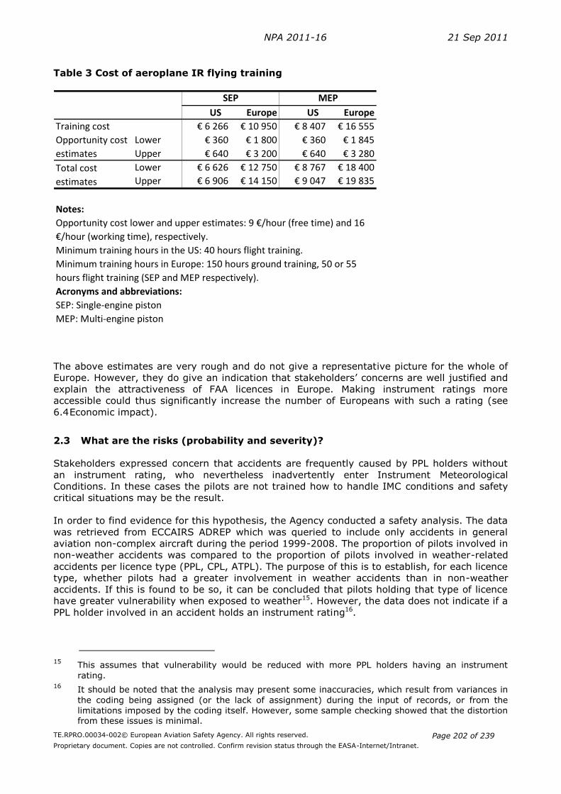
NPA 2011-16 21 Sep 2011
TE.RPRO.00034-002© European Aviation Safety Agency. All rights reserved.
Proprietary document. Copies are not controlled. Confirm revision status through the EASA-Internet/Intranet.
Page 202 of 239
Table 3 Cost of aeroplane IR flying training
US Europe US Europe
€ 6 266 € 10 950 € 8 407 € 16 555
Lower € 360 € 1 800 € 360 € 1 845
Upper € 640 € 3 200 € 640 € 3 280
Lower € 6 626 € 12 750 € 8 767 € 18 400
Upper € 6 906 € 14 150 € 9 047 € 19 835
Notes:
Acronyms and abbreviations:
SEP: Single-engine piston
MEP: Multi-engine piston
Opportunity cost
estimates
Training cost
Total cost
estimates
Minimum training hours in the US: 40 hours flight training.
Minimum training hours in Europe: 150 hours ground training, 50 or 55
hours flight training (SEP and MEP respectively).
SEP MEP
Opportunity cost lower and upper estimates: 9 €/hour (free time) and 16
€/hour (working time), respectively.
The above estimates are very rough and do not give a representative picture for the whole of
Europe. However, they do give an indication that stakeholders’ concerns are well justified and
explain the attractiveness of FAA licences in Europe. Making instrument ratings more
accessible could thus significantly increase the number of Europeans with such a rating (see
6.4 Economic impact).
2.3 What are the risks (probability and severity)?
Stakeholders expressed concern that accidents are frequently caused by PPL holders without
an instrument rating, who nevertheless inadvertently enter Instrument Meteorological
Conditions. In these cases the pilots are not trained how to handle IMC conditions and safety
critical situations may be the result.
In order to find evidence for this hypothesis, the Agency conducted a safety analysis. The data
was retrieved from ECCAIRS ADREP which was queried to include only accidents in general
aviation non-complex aircraft during the period 1999-2008. The proportion of pilots involved in
non-weather accidents was compared to the proportion of pilots involved in weather-related
accidents per licence type (PPL, CPL, ATPL). The purpose of this is to establish, for each licence
type, whether pilots had a greater involvement in weather accidents than in non-weather
accidents. If this is found to be so, it can be concluded that pilots holding that type of licence
have greater vulnerability when exposed to weather15. However, the data does not indicate if a
PPL holder involved in an accident holds an instrument rating16.
15
This assumes that vulnerability would be reduced with more PPL holders having an instrument
rating. 16
It should be noted that the analysis may present some inaccuracies, which result from variances in
the coding being assigned (or the lack of assignment) during the input of records, or from the
limitations imposed by the coding itself. However, some sample checking showed that the distortion from these issues is minimal.
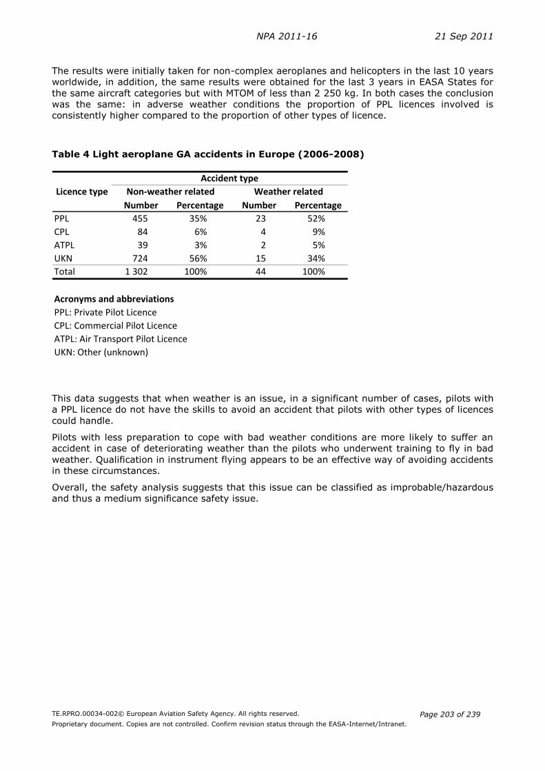
NPA 2011-16 21 Sep 2011
TE.RPRO.00034-002© European Aviation Safety Agency. All rights reserved.
Proprietary document. Copies are not controlled. Confirm revision status through the EASA-Internet/Intranet.
Page 203 of 239
The results were initially taken for non-complex aeroplanes and helicopters in the last 10 years
worldwide, in addition, the same results were obtained for the last 3 years in EASA States for
the same aircraft categories but with MTOM of less than 2 250 kg. In both cases the conclusion
was the same: in adverse weather conditions the proportion of PPL licences involved is
consistently higher compared to the proportion of other types of licence.
Table 4 Light aeroplane GA accidents in Europe (2006-2008)
Number Percentage Number Percentage
PPL 455 35% 23 52%
CPL 84 6% 4 9%
ATPL 39 3% 2 5%
UKN 724 56% 15 34%
Total 1 302 100% 44 100%
Acronyms and abbreviations
PPL: Private Pilot Licence
CPL: Commercial Pilot Licence
ATPL: Air Transport Pilot Licence
UKN: Other (unknown)
Accident type
Non-weather related Weather relatedLicence type
This data suggests that when weather is an issue, in a significant number of cases, pilots with
a PPL licence do not have the skills to avoid an accident that pilots with other types of licences
could handle.
Pilots with less preparation to cope with bad weather conditions are more likely to suffer an
accident in case of deteriorating weather than the pilots who underwent training to fly in bad
weather. Qualification in instrument flying appears to be an effective way of avoiding accidents
in these circumstances.
Overall, the safety analysis suggests that this issue can be classified as improbable/hazardous
and thus a medium significance safety issue.

NPA 2011-16 21 Sep 2011
TE.RPRO.00034-002© European Aviation Safety Agency. All rights reserved.
Proprietary document. Copies are not controlled. Confirm revision status through the EASA-Internet/Intranet.
Page 204 of 239
Table 5: Risk index matrix
Probability of occurrence
Severity of occurrence
Negligible Minor Major Hazardous Catastrophic
1 2 3 5 8
Extremely improbable
1
Improbable 2 10
Remote 3
Occasional 4
Frequent 5
NPA 2011-16 21 Sep 2011
TE.RPRO.00034-002© European Aviation Safety Agency. All rights reserved.
Proprietary document. Copies are not controlled. Confirm revision status through the EASA-Internet/Intranet.
Page 205 of 239
3 Objectives
The overall objectives of the Agency are defined in Article 2 of Regulation (EC) No 216/2008
(‘the Basic Regulation’). This proposal will contribute to the overall objectives by addressing
the issues outlined in Section 2.
The specific objective is therefore to improve access to the instrument rating for PPL and CPL
holders and thus increase the level of safety.
4 Identification of options
In order to achieve the above objective, the rulemaking group FCL.008 developed a number of
options, which were based on the broad ideas to lower requirements and, in parallel, to reduce
privileges where necessary to ensure a high level of safety. The basic characteristics discussed
were pre-requisites and crediting, flight instruction, theoretical knowledge instruction, skill test
as well as privileges.
Table 6 gives an overview of the characteristics for the options eventually identified by the
rulemaking group as feasible for the whole of Europe. Option 0 represents the baseline option
with no changes to the current Part-FCL. The requirements would thus remain unchanged from
Part-FCL as described in chapter 2.
Option 1 ‘En-route IR’ is a concept where the requirements are significantly reduced in terms
of prior flying experience (20 instead of 50 hours cross-country experience) and instrument
flight instruction (15 instead of 50 hours) as well as the amount of theoretical knowledge (100
instead of 150 hours) and the way the theoretical knowledge is acquired (only 10% classroom
training). On the other hand, the privileges are also significantly reduced by not allowing to
perform an approach or a landing in IMC. This is an entirely new concept for Europe.
Option 2 ‘accessible IR’ (or ‘competency-based IR’) follows a different approach from option 1
by reducing the amount of required instrument flight instruction only slightly (40 instead of 50
hours) but introducing a competency-based approach by crediting prior instrument flight time
based on a pre-course assessment. 30 out of the 40 hours instrument time are allowed in the
simulator, which is an increase in the simulator ratio as compared to JAR-FCL. The theoretical
knowledge instruction is lowered in the same way as it was done for option 1. As the final skill
test will cover the same exercises like the existing IR skill test in Part-FCL, this ‘accessible IR’
will give not only en-route IFR privileges but also full approach and landing privileges.
Option 3 combines the accessible IR from option 2 with the novel creation of an en-route IR
rating from option 1 and provides thus the most comprehensive change to the way instrument
ratings are issued in Europe.

NPA 2011-16 21 Sep 2011
TE.RPRO.00034-002© European Aviation Safety Agency. All rights reserved.
Proprietary document. Copies are not controlled. Confirm revision status through the EASA-Internet/Intranet.
Page 206 of 239
Table 6: Summary of options
Requirement Option 0
Part-FCL
Option 1
En-route IR
Option 2
Accessible IR
Option 3
Combination of Option 1 &
2
Flying Experience
Total flying experience Not specified Not specified Not specified See Option 1 & 2
Cross country as PIC 50 hours 20 hours 50 hours
Flying Instruction
Approved course Mandatory Mandatory Pre-course assessment
Approved course in an ATO
See Option 1 & 2
Instrument time 50 hours 15 hours 40 hours
Thereof permitted in simulator (max)
35 hours None 30 hours See Option 1 & 2
Thereof dual instruction
(at least)
10+40 hours in an ATO 5 hours by an IRI
10 hours in an ATO
15 hours by an IRI
10 hours in an ATO
See Option 1 & 2
Theoretical Knowledge – Training Requirement / Examination
Theoretical knowledge - Approved course of training including classroom instruction, certificate from approved school.
- IR(A) at least 150 hours (1 hour = 60 minutes instruction)
- At least 100 hours of theoretical knowledge instruction
E-learning will be allowed
10% classroom teaching
- At least 100 hours of theoretical knowledge instruction
E-learning will be allowed
10% classroom teaching
See Option 1 & 2
Examination procedures Responsibility of Member States
Procedure as in JAR-FCL
Responsibility of Member States
Reduced amount of questions
Responsibility of Member States
Reduced amount of questions
See Option 1 & 2
Privileges
Aeroplanes Any aircraft under IFR for which a class- or type-rating is held
Any aircraft under IFR for which a class- or type-rating is held
Any aircraft under IFR for which a class- or type-rating is held
See Option 1 & 2
Approach and landing in IMC Yes No Yes See Option 1 & 2
Acronyms and abbreviations: PIC: Pilot in Command
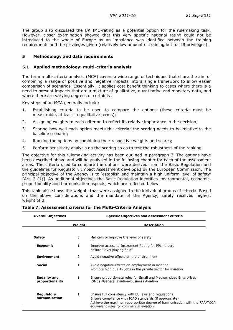
NPA 2011-16 21 Sep 2011
TE.RPRO.00034-002© European Aviation Safety Agency. All rights reserved.
Proprietary document. Copies are not controlled. Confirm revision status through the EASA-Internet/Intranet.
Page 207 of 239
The group also discussed the UK IMC-rating as a potential option for the rulemaking task.
However, closer examination showed that this very specific national rating could not be
introduced to the whole of Europe as an imbalance was identified between the training
requirements and the privileges given (relatively low amount of training but full IR privileges).
5 Methodology and data requirements
5.1 Applied methodology: multi-criteria analysis
The term multi-criteria analysis (MCA) covers a wide range of techniques that share the aim of
combining a range of positive and negative impacts into a single framework to allow easier
comparison of scenarios. Essentially, it applies cost benefit thinking to cases where there is a
need to present impacts that are a mixture of qualitative, quantitative and monetary data, and
where there are varying degrees of certainty.
Key steps of an MCA generally include:
1. Establishing criteria to be used to compare the options (these criteria must be
measurable, at least in qualitative terms);
2. Assigning weights to each criterion to reflect its relative importance in the decision;
3. Scoring how well each option meets the criteria; the scoring needs to be relative to the
baseline scenario;
4. Ranking the options by combining their respective weights and scores;
5. Perform sensitivity analysis on the scoring so as to test the robustness of the ranking.
The objective for this rulemaking activity has been outlined in paragraph 3. The options have
been described above and will be analysed in the following chapter for each of the assessment
areas. The criteria used to compare the options were derived from the Basic Regulation and
the guidelines for Regulatory Impact Assessment developed by the European Commission. The
principal objective of the Agency is to ‘establish and maintain a high uniform level of safety’
[Art. 2 (1)]. As additional objectives the Basic Regulation identifies environmental, economic,
proportionality and harmonisation aspects, which are reflected below.
This table also shows the weights that were assigned to the individual groups of criteria. Based
on the above considerations and the mandate of the Agency, safety received highest
weight of 3.
Table 7: Assessment criteria for the Multi-Criteria Analysis
Weight Description
Safety 3 Maintain or improve the level of safety
1 Improve access to Instrument Rating for PPL holders Ensure "level playing field"
Environment 2 Avoid negative effects on the environment
Social 1 Avoid negative effects on employment in aviation Promote high quality jobs in the private sector for aviation
Equality and proportionality
1 Ensure proportionate rules for Small and Medium sized Enterprises (SMEs)/General aviation/Business Aviation
Regulatory harmonisation
1 Ensure full consistency with EU laws and regulations Ensure compliance with ICAO standards (if appropriate) Achieve the maximum appropriate degree of harmonisation with the FAA/TCCA equivalent rules for commercial aviation
Overall Objectives Specific Objectives and assessment criteria
Economic

NPA 2011-16 21 Sep 2011
TE.RPRO.00034-002© European Aviation Safety Agency. All rights reserved.
Proprietary document. Copies are not controlled. Confirm revision status through the EASA-Internet/Intranet.
Page 208 of 239
Environmental impacts are attributed with a weight of 2 as the Agency has certain specific
responsibilities in this area related to noise and emissions. For the same reason impacts on the
other assessment areas are attributed with a weight of 1 since these areas are to be duly
considered when developing the implementing rules. Each option developed below will be
assessed based on the above criteria. Scores are used to show the degree to which each of the
options achieves the assessment criteria. The scoring is performed on a scale between -5 and
+5.
Table 8 gives an overview of the scores and their interpretation.
Table 8: Scores for the Multi-criteria analysis
Score Descriptions Example for scoring options
+5 Highly positive impact Highly positive safety, social or environmental protection impact. Savings of more than 5% of annual turnover for any single firm; Total annual savings of more than 100 million euros
+3 Medium positive impact Medium positive social, safety or environmental protection impact. Savings of 1% - 5% of annual turnover for any single firm; Total annual savings of 10-100 million euros
+1 Low positive impact Low positive safety, social or environmental protection impact. Savings of less than 1% of annual turnover for any single firm; Total annual savings of less than 10 million euros
0 No impact
-1 Low negative impact Low negative safety, social or environmental protection impact. Costs of less than 1% of annual turnover for any single firm; Total annual costs of less than 10 million euros
-3 Medium negative impact Medium negative safety, social or environmental protection impact. Costs of 1% - 5% of annual turnover for any single firm; Total annual costs of 10-100 million euros
-5 Highly negative impact Highly negative safety, social or environmental protection impact. Costs of more than 5% of annual turnover for any single firm; Total annual costs of more than 100 million euros
5.2 Data requirements
There is a shortage of up-to-date and comprehensive data describing the general aviation
sector in Europe and its safety record. Unlike commercial air transport, general aviation does
not provide data on traffic, so there are only estimates available based on the average annual
flight hours per aircraft category. The available safety statistics also do not usually include
information whether the pilot had an instrument rating or not.
For this analysis the costs of IR training were estimated by using publicly available data from
6 flight training organisations (marked as FTO A to FTO F). Some of these schools operate only
in Europe or in the United States, and some of them offer IR trainings on both continents.
FTO C gave prices for the same training in the USA, the United Kingdom and two Member
States in the continental Europe.
The Agency collected information on the number of PPL and IR holders by surveying national
aviation authorities. All 31 EASA Member States were asked to provide information on the
number of licence holders. The results of the present survey were compared to a similar 2009
survey to get a view of the latest developments in the number of licence holders.

NPA 2011-16 21 Sep 2011
TE.RPRO.00034-002© European Aviation Safety Agency. All rights reserved.
Proprietary document. Copies are not controlled. Confirm revision status through the EASA-Internet/Intranet.
Page 209 of 239
12 EASA Member States did not reply to the 2011 questionnaire. In case of 9 countries, the
Agency could use data from the previous survey but no figures were available for Cyprus,
Liechtenstein and Spain. Neither population nor GDP per capita (per person) had enough
explanatory value for the number of PPL or IR licences, so it was decided not to estimate these
values as they would only have a marginal impact on the overall results.

NPA 2011-16 21 Sep 2011
TE.RPRO.00034-002© European Aviation Safety Agency. All rights reserved.
Proprietary document. Copies are not controlled. Confirm revision status through the EASA-Internet/Intranet.
Page 210 of 239
6 Analysis of impacts
In this section the major impacts of the options developed in the previous chapter 4 are
discussed. For each option safety, environmental, economic and social impacts are discussed
as well regulatory harmonisation issues. Some of these impacts are quantifiable, but most are
not. For this reason, the impacts are converted in scores in line with the MCA methodology
described in section 5.1.
6.1 Safety impact
Option 0 is defined as ‘no regulatory change’, i.e. the JAR-FCL rules would continue to apply in
the EASA system. The safety risks would thus remain as described in section 2.3. This has
been evaluated as a medium significance safety risk (MCA score -3).
Option 1 is expected to reduce the safety risks by facilitating a wider skill-base to private
pilots. There is both a qualitative and a quantitative element to the expected positive safety
impact. Qualitatively, the ‘en-route’ pilots will be better trained and prepared for unexpected
encounters with adverse weather conditions. Due to the expected higher number of pilots with
such an en-route instrument rating (see economic impact below) there will be quantitative
increase in key navigation skills. On the other hand, ‘en-route’ pilots will have a more
restricted range of skills than full IR-rated pilots. The potential increase in safety risks induced
by these lower training requirements is mitigated by not allowing ‘en-route’ pilots to perform
approach and landing in IMC conditions. Special training modules for handling busy airspace
and unforeseen landings will further ensure that there is a low positive safety impact expected
from this option (MCA score +1).
Option 2 proposes to introduce a modular approach with an entry level ‘accessible IR’ rating
that is likely to increase the number of pilots with IR, albeit not as much as is expected for
option 1. However, the pilots with the accessible competency-based IR will essentially have all
relevant skills needed for the operation of aeroplanes in IMC conditions and under IFR for all
flight phases. As this option is based on a competency-based approach, it is expected that
future ‘en-route’ pilots will use this option to gain the full IR privileges later on. This should
lead to an increase of pilots starting the training for the ‘accessible IR’ in the long term. It is
therefore expected to also create a low positive safety impact (MCA score +1).
Option 3 proposes to introduce both an en-route instrument rating and the ‘accessible
competency-based IR’. This solution is expected to attract most pilots to acquire IR privileges.
It reduces safety risks by facilitating a wider skill-base with private pilots as compared to
options 1 and 2. Therefore, this option is expected to have a medium positive safety impact
(MCA score +3).
6.2 Environmental impact
Powered flying by PPL holders, like commercial air transport operations or any other mode of
transport, might have negative impacts on the environment in terms of noise and gaseous
emissions. Although the general aviation fleet is bigger than the commercial air transport fleet,
it is utilised far less intensively in terms of flight hours.
According to Eurocontrol data, IFR flights in EASA Member States in the cargo, low-cost, non-
scheduled and scheduled market segments amounted to more than 1 billion flight hours in
2009. During the same period the estimated hours flown by EASA Member States general
aviation aeroplanes was somewhat below 4 million flight hours, which represents less than half
percent of the total civil aviation flight hours. The environmental impacts are further decreased
by the lower fuel consumption and noise emissions of the aeroplane types utilised by PPL
holders, as compared to commercial operations as most private powered flying involves piston-
engine aircraft with a MTOW not exceeding 2 000kg.
Option 0 maintains the current situation and thus has no environmental impact.

NPA 2011-16 21 Sep 2011
TE.RPRO.00034-002© European Aviation Safety Agency. All rights reserved.
Proprietary document. Copies are not controlled. Confirm revision status through the EASA-Internet/Intranet.
Page 211 of 239
In option 1 private pilots will have a form of instrument rating that does not include approach
and landing privileges. It is therefore not expected to significantly change the number of flying
hours.
Option 2 and 3 include the ‘accessible IR’ which is expected to give more pilots the possibility
to perform IFR flights. On the one hand, this may increase the number of cross-country flights
as more aircraft owners may plan a private flight even if the weather conditions are not stable.
On the other hand, the privilege of flying in IMC conditions may also allow pilots to take a
more direct route, which would reduce the flight time and therefore fuel consumption and
gaseous emissions.
Another point to consider is that most private pilots have a certain budget to spend on private
flights. This would indicate that IMC-flying privileges may increase the number of distance
flights, but would not affect the overall flight hours as pilots would reduce their flight hours in
local flights.
Given the overall magnitude of greenhouse gas emissions by general aviation and the above
considerations related to flight routes and flying budgets no significant effect on greenhouse
gas emissions, local air quality and noise are expected for any of the options (MCA scores for
all options is 0).
6.3 Social impact
Aviation training can be considered as a core activity of general aviation. General aviation is
not only offering jobs itself but it is also one of the very important sources of qualified staff
from which the commercial aviation sector can draw. Many of the trainee pilots, after building
the number of the hours in the air, subsequently move to work in commercial aviation
(European Commission, 2007). Although not on a scale comparable to the services provided by
commercial air carriers, part of the general aviation function is the provision of transportation
for individuals and business.
Underutilised regional airports might also benefit from traffic growth caused by the increase in
IR training and future traffic under IFR.
Options 1 and 2 are expected to have a low positive social impact as they would increase the
individual utility for European citizens (MCA score +1). Option 3 combines the impact of
options 1 and 2 and therefore is expected to have a low to medium positive social impact (MCA
score +3).
6.4 Economic impact
The trend for a reduction of European PPL holders with an instrument rating is parallel to the
trend of reduced numbers of PPL holders (see Table 17). Overall, this indicates a reduced
activity in the sector and thus certain negative economic effects are induced, notably for aero
clubs, flight schools and other businesses relying on general aviation aircraft for transport.
Feedback from stakeholders indicate that pilot trainees are sensitive to direct training costs as
well as the time necessary to acquire the skills. The proposals in this NPA/RIA are intended to
make IRs more accessible to European citizens by reducing, where possible and adequate to
the type of operation, the training requirements and thus related costs as well as time needs.
In order to predict the possible impacts of more accessible instrument rating requirements, it
is necessary to answer two questions:
How much cheaper and less time-intensive would the new instrument rating be; and
How many more pilots could be expected for a new instrument rating?
In order to answer the first question, information on the cost of obtaining an instrument rating
in Europe was collected. It was found that a large proportion of the costs (at least 80%) are

NPA 2011-16 21 Sep 2011
TE.RPRO.00034-002© European Aviation Safety Agency. All rights reserved.
Proprietary document. Copies are not controlled. Confirm revision status through the EASA-Internet/Intranet.
Page 212 of 239
variable costs, depending on the number of flight hours, dual instruction and compulsory
classroom instruction. In order to obtain the final estimate for the increase in instrument
ratings for the different options, the elasticity is multiplied with the percentage change in IR
costs estimated.
Table 9 gives an overview of the cost estimates for each option. As described in section 2, the
opportunity costs reflect the fact that time needed to study in a classroom also represents an
implicit cost for flight students. Overall, the results show that the ‘en-route’ rating is expected
to reduce costs by more than 50% and the ‘accessible IR’ by almost 20% compared to the
current situation.
In order to answer the second question and estimate how much more instrument ratings can
be expected based on the above cost reductions, the so-called price elasticity needs to be
estimated. The elasticity expresses the expected percentage change in demand for a 1%
change in price (i.e. training costs).17
It is assumed that the demand for the instrument ratings is elastic. An elastic demand means
that for any given change in price, there will be a larger change in the quantity demanded. In
other words, the quantity of PPL holders with IR is going to respond with a marked increase to
a decrease in training costs (including related opportunity costs, see end of section 2.2
Comparison of FAA and JAR-FCL requirements).
Because of a lack of both historical data on demand for IR and surveys of customers’
preferences, the price elasticity of demand for PPL IR was estimated by taking into account its
most important influencing factors: substitute goods, the necessity of the training, and the
price and income ratio of trainees.
The more and closer the alternatives or substitutes available, the higher the elasticity is likely
to be, as consumers can easily switch from one good to another if there is a change in price. If
no close substitutes are available, the substitution effect will be small and the demand
inelastic. In case of the present European instrument rating (option 0), the FAA PPL with
instrument rating might be considered a close substitute. The availability of substitutes
suggests a high elasticity and this analysis therefore assumes an elasticity of -1.5 (see Annex
2: Glossary and Table 19). This elasticity implies that for a 1% decrease in training costs the
demand for IR ratings will increase by 1.5%.
In order to obtain the final estimate for the increase in instrument ratings for the different
options, the elasticity is multiplied with the percentage change in IR costs estimated.
17 See Annex 2: Glossary.

NPA 2011-16 21 Sep 2011
TE.RPRO.00034-002© European Aviation Safety Agency. All rights reserved.
Proprietary document. Copies are not controlled. Confirm revision status through the EASA-Internet/Intranet.
Page 213 of 239
Table 9: Estimated costs of IR training and estimated number of instrument ratings
Aircraft flight hours € 151 € 16 15 € 2 511 15 € 2 511 10 € 1 674 15 or 25 € 2 511 or € 4 185
Simulator flight hours € 104 € 16 35 € 4 214 0 € 0 30 € 3 612 0 or 15 € 0 or € 1 806
Dual instruction € 36 50 € 1 780 15 € 534 40 € 1 424 15 or 25 € 534 or € 1 424
Theory course instruction € 36 € 16 15 € 774 10 € 516 10 € 516 10 € 516
Total variable costs € 9 279 € 3 561 € 7 226 € 3 561 or € 7 931
Fixed training costs € 1 282 € 1 282 € 1 282 € 1 282
Total cost of IR training including opportunity cost € 10 561 € 4 843 € 8 508 €4 843 or € 9 213
Decrease in TC of IR training 0% 54% 19% 19%–54%
Estimated number of IR holders 6 364 11 532 8 220 12 000–20 000
Increase compared to Option 0 (percentage) 0% 81% 29% 100%–300%
Notes:
Dual instruction has no opportunity cost because it is part of the aircraft flight hours.
Fixed training costs equal the average estimated non-variable training cost.
Assumed price elasticity of IR training: -1.5
Opportunity cost: €16/hour
In option 3 the estimated values and percentages are rounded to the nearest thousand and tens, respectively.
Acronyms and abbreviations:
IR: instrument rating
SEP: single engine piston aircraft
Description of options
Cost elementTraining cost
Opportunity
cost
Option 3
Accessible IRPart-FCL En-route IRCombination of
Option 1 & 2
Option 0 Option 1 Option 2
UnitUnitUnitUnit Total costTotal cost Total costTotal cost
When estimating the effects of the options on the potential increase in the number of IR
training attendees, it has to be noted that the price of training might not be the single most
important explanatory factor. The length, relevance and flexibility of the training and
examinations might also be an influencing factor in the decision whether or not to obtain an IR
(and whether to obtain it in Europe or overseas).
An estimate for the upper limit of the number of IR holders could be based on the share of IR
holders in the PPL(A) holder population in the US. According to the latest data available, there
are roughly twice as many PPL(A) holders and around nine times more IR holders in the US
than in Europe (Table 18). If European PPL(A) holders had the same share of IR as their
American counterparts, that would mean 33 000 IR holders, which would be a four-fold
increase in the number of PPL IR holders compared to the present situation.
The relatively high (26.8%) ratio of IR holders in the US is considered the upper limit for this
analysis (see Table 18).
The analysis of options 1, 2 and 3 will estimate how close the number and share of IR holders
in Europe might get to this upper limit.
This analysis is based on the following uncertainties:
The forecast of Part-FCL IR holders willing to move to another rating option
The forecast of a ‘En-route’ IR holders to move at a later stage to an ‘Accessible IR’
rating
The fact that the price elasticity for the demand in IR training is estimated with no
historical data or surveys of customer’s preferences available (see Annex 3).
Therefore the outcome of the analysis is to be considered indicative. Low and high estimates
are also given to provide plausible ranges for the estimates.
Option 1:

NPA 2011-16 21 Sep 2011
TE.RPRO.00034-002© European Aviation Safety Agency. All rights reserved.
Proprietary document. Copies are not controlled. Confirm revision status through the EASA-Internet/Intranet.
Page 214 of 239
Option 1 would cut the cost of training by more than half, which would lead to a more than
80% increase in the number of instrument ratings in the long run, from around 6 400 to
almost 11 500 (see Table 9). This estimate takes into account the decrease in opportunity
costs due to the lower number of training hours and is considered a low positive economic
impact (MCA score +1).
Because of the uncertainties identified above, the total number of IR holders may range
between 9 000 (low estimate) and 12 000 (high estimate).
Option 2:
Option 2 is estimated to lead to an almost 20% decrease in costs, which would lead to more
than 8 200 IR holders in total. Because of the price elasticity of demand, any decrease in
training costs would mean an increase in total revenue for the European IR flight training
industry as a whole18. Overall, this is considered a low positive economic impact (MCA score
+1).
Because of the uncertainties identified above, the increase in the total number of IR holders
may range between 8 000 (low estimate) and 14 400 (high estimate).
Option 3:
Option 3 is a combination of option 1 and option 2. Because of the uncertainties explained for
Options 1 and 2, there is a range of plausible outcomes, which will be described below as low,
high and best estimates.
Best estimate
Taking into account the above analysis and uncertainties, the best estimate is a significant
increase by some 280% from 6400 to 18 000 IR holders. These 18 000 IR holders would
include all types of instrument ratings.
Note also that such a significant change would not be expected to happen from one year to
another but the result must be seen as a simulation of an optimal situation in the future with
all other conditions remaining the same. A 5 year adjustment period is assumed for this
analysis.
Note that the exact value of the increase is less relevant than the outcome that option 3 will
generate higher positive economic effects as compared to option 0, 1 and 2 and is estimated
to have overall a medium positive economic impact (MCA score +3).
Lower estimate
Looking at the strict minimum impact, the price elasticity applied to the 6 394 Part-FCL IR
holders shows in increase of approximately 5 000 IR holders with option 1. For this low
estimate it is assumed that this is the total potential increase and a combination of option 1
and 2 will not expand the pool of future IR holders. Thus the low estimate for option 3 is the
same as for option 1: 11 500.
Upper estimate
18
A decrease of training costs has two offsetting effects for the flight training industry. One is a
decrease of revenue per trainee and the other is the increase of revenue because of the increasing
number of trainees. A price elastic demand means that a 1% decrease in price, which equals a 1% decrease in revenues, results in a more than 1% increase in demand, i.e. a more than 1% increase
in revenues. The increase in demand is therefore going to result in a net increase in revenue for the industry.

NPA 2011-16 21 Sep 2011
TE.RPRO.00034-002© European Aviation Safety Agency. All rights reserved.
Proprietary document. Copies are not controlled. Confirm revision status through the EASA-Internet/Intranet.
Page 215 of 239
If we assume that:
the 6 400 of Part-FCL pilots that currently choose option 0 would remain in the future
because this training has a higher level compared to option 1 and option 2, in this case
they would not move to one of the new option 1 and option 2 ratings (in economic
terms there would be no crowding out of demand between the different ratings);
the 11 500 pilots choosing option 1 (en-route IR) are new pilots, not willing to get an
option 0 or option 2 training;
the 8 200 pilots choosing option 2 (accessible IR) are new pilots, not willing to get an
option 0 or option 1 training;
then the maximum total number of Part-FCL, en-route and accessible IR holders could reach
26 100. This estimate gives a theoretical maximum for IR holders. It does not address the
issue of double-counting (e.g. one pilot trained for En-route IR, option 1, could decide to move
to Accessible IR, option 2, which makes the change in total IR holders neutral. However, it is
still below the 33 000 potential IR holders in Europe if the US IR holder share is applied to
Europe (see Table 18). This shows that this theoretical number of 26 200 European IR holders
is a good basis for comparison with other countries.
6.5 Proportionality issues
Option 0, the present IR training under JAR-FCL requirements is well-adjusted to the needs of
commercial pilot licence holders but much less to the needs of private pilots. Option 0 has a
low negative impact (-1) because general aviation pilots can hardly attend the training and
therefore small and medium-sized organisations offering trainings mostly for private pilots are
disproportionately affected.
Option 1 offers a valuable building block while offering appropriate privileges. It does not
require the same excessive financial and time burden from private pilots as option 0. This
option is considered more proportionate as it allows for an entry level instrument rating with
limited privileges, which is more adequate to the needs of general aviation pilots, therefore a
low positive impact is expected (+1).
Option 2 also offers a less burdensome way of acquiring the IR qualification but the skill step
from PPL might still be too large for some candidates. Option 2, however, unlike option 1, also
includes approach and landing privileges, so a low positive impact is expected (+1).
Option 3 offers both the en-route IR and the accessible competency-based IR and thus
combines the benefits of the two, adding the positive effects of option 1 and option 2 to
achieve a full IR rating under more proportionate conditions. A medium positive impact is
expected (+3).
6.6 Impact on regulatory coordination and harmonisation
No issues identified.

NPA 2011-16 21 Sep 2011
TE.RPRO.00034-002© European Aviation Safety Agency. All rights reserved.
Proprietary document. Copies are not controlled. Confirm revision status through the EASA-Internet/Intranet.
Page 216 of 239
7 Conclusion and preferred option
7.1 Comparing the options
Objectives / Criteria Weights
Option
0
Option
1
Option
2
Option
3
Option 0 Option 1 Option
2
Option 3
Safety 3 -1 1 1 3 -3 3 3 9
Environment 2
Social 1 1 1 3 1 1 3
Economic 1 -1 1 1 3 -1 1 1 3
Proportionality 1 -1 1 1 3 -1 1 1 3
Regulatory co-ordination and
harmonization
1
Total -5 6 6 18
Scores (unweighted) Scores (weighted)
Note:
Empty cells mean no impact.
In conclusion, the Agency recommends option 3 as it is expected to increase the level of safety
by widening the skill base of European PPL holders. Furthermore, positive economic and social
effects are expected due to the positive effects on flight schools and economic activity in
general aviation. Option 3 is considered more favourable than option 2 as it includes the
European EIR, which is expected to further widen the skills of European PPL holders and
increase utility of general aviation while maintaining the level of safety.
7.2 Sensitivity analysis
There is a certain degree of uncertainty in every RIA due to the assumptions made. This
section describes whether the assessment is particularly sensitive to an assumption or
variable.
One of the main uncertainties connected with the quantification of the impacts is related to the
forecast on the number of IR holders. The forecast on the number of IR holders relies heavily
on the price elasticity of the demand for IR training.
In practice there is no particular elasticity rate that could indisputably be proven correct. The
analysis is sensitive to the type of the elasticity (whether the demand is elastic or inelastic),
but it is very certain to be elastic. Although the exact value of the elasticity is quite uncertain,
once we are certain that the demand is elastic, it is not going to have an impact on the result
of comparing the various options.
It should also be noted that the forecast on the number of IR holders is rather insensitive to
the value of time used to calculate the opportunity cost of various options.

NPA 2011-16 21 Sep 2011
TE.RPRO.00034-002© European Aviation Safety Agency. All rights reserved.
Proprietary document. Copies are not controlled. Confirm revision status through the EASA-Internet/Intranet.
Page 217 of 239
Annex 1: Data
Table 10: USA, UK and Europe IR training pricing comparison
Rating USA Europe UK
Private Pilot C172 € 8 810 € 10 031 € 12 656
IFR Single-Engine € 7 351 € 10 085 € 12 723
IFR Multi-Engine € 8 407 € 15 038 € 21 379
Source:
FTO C
Notes:
Prices of PPL(A) trainings.
EUR 1 = GBP 0.8578
EUR 1 = USD 1.3257
FTO: Flight Training Organisation
Prices include value added tax where relevant
Exchange rates: European Central Bank annual
average reference exchange rates for 2010
Table 11: Cost elements of an instrument rating training in the USA
Description Price Share
FAA IR: 40hrs IR flight (plane and simulator) € 2 866 54%
Flight instruction 25hrs € 1 490 28%
Ground instruction 10hrs € 596 11%
Theory test € 60 1%
Flight test € 264 5%
Total € 5 276 100%
Source:
FTO A
Notes:
EUR 1 = USD 1.3257
Prices include value added tax where relevant
FTO: Flight Training Organisation
Exchange rates: European Central Bank annual average reference
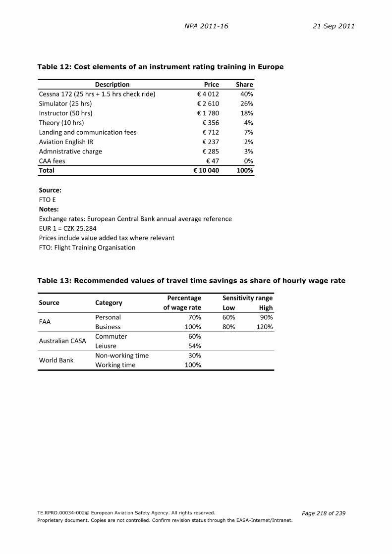
NPA 2011-16 21 Sep 2011
TE.RPRO.00034-002© European Aviation Safety Agency. All rights reserved.
Proprietary document. Copies are not controlled. Confirm revision status through the EASA-Internet/Intranet.
Page 218 of 239
Table 12: Cost elements of an instrument rating training in Europe
Description Price Share
Cessna 172 (25 hrs + 1.5 hrs check ride) € 4 012 40%
Simulator (25 hrs) € 2 610 26%
Instructor (50 hrs) € 1 780 18%
Theory (10 hrs) € 356 4%
Landing and communication fees € 712 7%
Aviation English IR € 237 2%
Admnistrative charge € 285 3%
CAA fees € 47 0%
Total € 10 040 100%
Source:
FTO E
Notes:
EUR 1 = CZK 25.284
Prices include value added tax where relevant
FTO: Flight Training Organisation
Exchange rates: European Central Bank annual average reference
Table 13: Recommended values of travel time savings as share of hourly wage rate
Low High
Personal 70% 60% 90%
Business 100% 80% 120%
Commuter 60%
Leiusre 54%
Non-working time 30%
Working time 100%
FAA
Australian CASA
World Bank
CategorySensitivity rangePercentage
of wage rateSource

NPA 2011-16 21 Sep 2011
TE.RPRO.00034-002© European Aviation Safety Agency. All rights reserved.
Proprietary document. Copies are not controlled. Confirm revision status through the EASA-Internet/Intranet.
Page 219 of 239
Table 14: Average gross annual earnings of full-time employees
Member State Earning
Austria € 36 673
Belgium € 37 674
Bulgaria € 2 626
Cyprus € 21 310
Czech Republic € 8 284
Denmark € 53 165
Estonia :
Finland € 36 126
France € 31 369
Germany € 42 382
Greece € 16 739
Hungary € 8 952
Iceland € 36 764
Ireland € 40 462
Italy :
Latvia € 6 690
Liechtenstein :
Lithuania € 3 017
Luxembourg € 45 284
Malta € 11 669
Netherlands € 38 700
Norway € 47 221
Poland € 6 270
Portugal € 15 930
Romania € 4 828
Slovakia € 8 400
Slovenia :
Spain € 21 150
Sweden € 36 871
Switzerland € 46 058
United Kingdom € 46 051
EU27 € 31 302
Notes:
Source:
Eurostat
2002: Iceland
2003: Greece
2007: Bulgaria, Denmark, Finland, Hungary,
Latvia, Luxembourg, Romania, Slovakia,
Sweden, United Kingdom
2005: Ireland, Netherlands, Poland
2006: Austria, Belgium, Cyprus, Czech
Republic, EU27, France, Germany, Malta,
Norway, Portugal, Spain, Switzerland
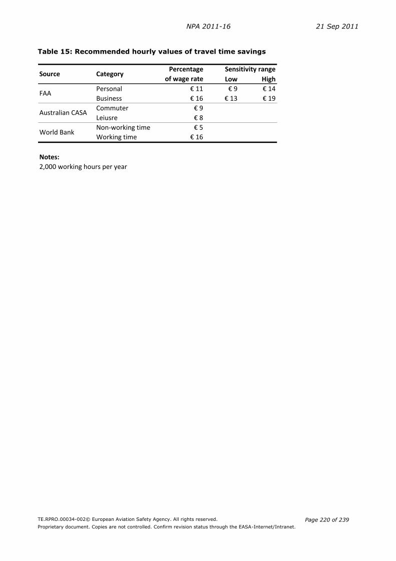
NPA 2011-16 21 Sep 2011
TE.RPRO.00034-002© European Aviation Safety Agency. All rights reserved.
Proprietary document. Copies are not controlled. Confirm revision status through the EASA-Internet/Intranet.
Page 220 of 239
Table 15: Recommended hourly values of travel time savings
Low High
Personal € 11 € 9 € 14
Business € 16 € 13 € 19
Commuter € 9
Leiusre € 8
Non-working time € 5
Working time € 16
Notes:
2,000 working hours per year
World Bank
Source CategoryPercentage
of wage rate
Sensitivity range
FAA
Australian CASA

NPA 2011-16 21 Sep 2011
TE.RPRO.00034-002© European Aviation Safety Agency. All rights reserved.
Proprietary document. Copies are not controlled. Confirm revision status through the EASA-Internet/Intranet.
Page 221 of 239
Table 16: PPL licences and instrument ratings in Europe
PPL (A) PPL (A/IR) Share of IR
Austria 5 778 880 15.2%
Belgium 2 125 48 2.3%
Bulgaria 16 0 0.0%
Cyprus : : :
Czech Republic 1 838 132 7.2%
Denmark 1 907 26 1.4%
Estonia 5 0 0.0%
Finland 2 001 111 5.5%
France 27 778 536 1.9%
Germany 29 853 1 738 5.8%
Greece 760 50 6.6%
Hungary 4 700 270 5.7%
Iceland 526 40 7.6%
Ireland 790 19 2.4%
Italy 6 608 101 1.5%
Latvia 101 2 2.0%
Liechtenstein : : :
Lithuania 192 1 0.5%
Luxembourg 160 93 58.1%
Malta 75 0 0.0%
Netherlands 2 836 70 2.5%
Norway 1 305 21 1.6%
Poland 1 994 32 1.6%
Portugal 726 7 1.0%
Romania 154 7 4.5%
Slovakia 719 3 0.4%
Slovenia 95 3 3.2%
Spain : : :
Sweden 3 712 372 10.0%
Switzerland 5 581 205 3.7%
UK 20 542 1 597 7.8%
Total 122 877 6 364 5.2%
Notes:
Country
Denmark, Greece, Ireland, Italy, Luxembourg, Malta,
Portugal, Romania, Slovenia: 2009
2009, 2011

NPA 2011-16 21 Sep 2011
TE.RPRO.00034-002© European Aviation Safety Agency. All rights reserved.
Proprietary document. Copies are not controlled. Confirm revision status through the EASA-Internet/Intranet.
Page 222 of 239
Table 17: Development of PPL with IR between 2009 and 2011
PPL (A) PPL (A/IR) IR share PPL (A) PPL (A/IR) IR share Number Percent
Belgium 2 070 39 1.9% 2 125 48 2.3% 9 23.1%
Czech Republic 1 648 38 2.3% 1 838 132 7.2% 94 247.4%
France 31 094 2 405 7.7% 27 778 536 1.9% -1 869 -77.7%
Iceland 549 22 4.0% 526 40 7.6% 18 81.8%
Latvia 95 3 3.2% 101 2 2.0% -1 -33.3%
Lithuania 257 4 1.6% 192 1 0.5% -3 -75.0%
Netherlands 2 946 63 2.1% 2 836 70 2.5% 7 11.1%
Norway 1 596 167 10.5% 1 305 21 1.6% -146 -87.4%
Sweden 4 055 396 9.8% 3 712 372 10.0% -24 -6.1%
UK 19 256 1 365 7.1% 20 542 1 597 7.8% 232 17.0%
Total 63 566 4 502 7.1% 60 955 2 819 4.6% -1 683 -37.4%
Aeroplane Private Pilot Licences and Instrument Ratings - Direct Comparison
Country2009 2011 Change in PPL(A/IR)
Table 18 Number of PPL(A) and IR holders in the EASA-31 and the US
PPL (A) PPL (A/IR) Share of IR
EASA-31 122 877 6 364 5.2%
US 213 635 57 327 26.8%
EASA-31 max 122 877 32 973 26.8%
Change 26 609
Annex 2: Glossary
Opportunity Cost and Value of Time (VOT)
In transport economics the value of travellers’ time is usually expressed as a proportion of the
wage rate or as a value deduced from stated preference methods, i.e. asking people directly or
indirectly for their willingness to pay (WTP) to save time with an alternative option. These two
methods, however, can also be combined (WTP expressed as a percentage of the wage rate).
The Federal Aviation Administration (FAA, 2007) recommends the hourly values for travel time
saving to be 100% of the hourly income for business purposes and 70% of the hourly income
for personal purposes. These values are based on airline passenger surveys on individuals’
willingness to pay for leisure time.
The Australian Civil Aviation Safety Authority (CASA, 2010) recommends 60 and 54% of the
average wage rate for working and leisure time in its Standard Economic Values Guidelines.
The World Bank (1998) recommends to value leisure time saved at about 30% of the hourly
wage rate if there is no evidence to the contrary. Savings on working time are recommended
to be valued at 100% of the wage rate including benefits. (For a summary of recommendations
see Table 13.)

NPA 2011-16 21 Sep 2011
TE.RPRO.00034-002© European Aviation Safety Agency. All rights reserved.
Proprietary document. Copies are not controlled. Confirm revision status through the EASA-Internet/Intranet.
Page 223 of 239
It is recognised that hourly incomes of Private Pilot Licence (PPL) holders tend to be higher
than those of the average population. Estimates for the Value of Time based on national or
European average wage rates (see Table 15) can therefore be considered conservative for the
purposes of this RIA.
If we assume that PPL holders prepare for their Instrument Rating (IR) in their free time, then
less than 100% of the hourly wage rate should be used for the Value of Time estimates. When
training cannot be expected to be completed in one’s free time (because of the length of the
training and/or because of its scheduling), then the value of working time (i.e. VOT estimates
for business purposes) should be used.
Price elasticity of demand
The price elasticity of demand shows the responsiveness of the quantity of a good or service
demanded to changes in its price. Changes in the quantity of training demanded and its price
are measured in percentage. When a 1% change in price results to a less than 1% change in
the quantity demanded, the demand is inelastic. When a 1% change in price results in an
exactly 1% change in the quantity demanded, the demand is unit elastic. And when a 1%
change in price result in a more than 1% change in the quantity demanded, the demand is
elastic.
The higher the percentage of the consumer’s income that the training’s price represents, the
higher the elasticity tends to be, as people will pay more attention when purchasing the good
because of its cost. Participating in an IR rating is a one-off event, not subject to habitual
consumption, which also increases trainees’ sensitivity to price. Although PPL holders tend to
have higher income than the average population, the several thousand euro cost of training
(see 2.2 Comparison of FAA and JAR-FCL requirements) means that they are highly willing to
look for more favourable prices (they might even be willing to attend trainings overseas). The
training for IR is not a service that represents only a negligible portion of a consumer’s budget,
so the income effect will be significant and the demand will be elastic.
Generally speaking, the more necessary goods are, the more price inelastic their demand is
going to be, as people will attempt to buy them no matter the price. Flight training for private
pilots, in general, and the IR rating, in particular, can be considered low necessity, therefore
its demand is going to be highly responsive to any changes in price.
Price elasticity of demand for air travel
Based on the above reasoning, it is clear that the demand for PPL IR training is price elastic. In
a 2008 paper Gillen et al. reviewed the economics and business literature on empirically-
estimated own price elasticities of demand for air travel in developed countries. Their meta-
analyses combined the results of 21 studies and identified six distinct markets for air travel. A
summary of their finding is presented in Table 19.
Demands for air transport were found to be less elastic for longer flights than for shorter ones
because of the diminishing availability of alternative modes of transport as the travelled
distance increases. Leisure travellers seemed to be more price sensitive than business
travellers: leisure travellers were more likely to postpone trips in response to higher fares, or
to shop around for more affordable fares.
Pilots who fly long-haul or for business purposes most probably have an IR already (and they
are also very likely to hold a commercial licence). PPL holders who fly short range might be
one of the largest groups who might add an IR to their existing qualification. The price
elasticity of this group in air travel is around -1.5.
There is a degree of uncertainty in estimating price elasticities for the demand for IR training
because potential candidates for the training might come from various subgroups of present

NPA 2011-16 21 Sep 2011
TE.RPRO.00034-002© European Aviation Safety Agency. All rights reserved.
Proprietary document. Copies are not controlled. Confirm revision status through the EASA-Internet/Intranet.
Page 224 of 239
PPL holders. However, our estimates based on the economic theory and the values from
empirical studies confirm both the assumption that the training is price sensitive and the
elasticity is around -1.5, i.e. for a 1% increase in price the demand for air travel would
decrease by 1.5%.
Table 19 Price elasticities of demand for air travel
Min Max
Long-haul international business -0.265 -0.475 -0.198
Long-haul international leisure -1.040 -1.700 -0.560
Long-haul domestic business -1.150 -1.428 -0.836
Long-haul domestic leisure -1.104 -1.228 -0.787
Short-haul business -0.700 -0.783 -0.595
Short-haul leisure -1.520 -1.743 -1.288
Notes:
The range of values capture the middle one-half of the estimates
Source:
Gillen et al. (2008)
RangeMarket segment Median
Annex 3: References
CASA (2010): Standard Economic Values Guidelines. Version 3.1: November 2010.
European Commission (2007): General Aviation in the European Community. Discussion
Paper. Brussels, 1 February 2007. Available at
http://ec.europa.eu/transport/air_portal/internal_market/doc/general_av_discussion_pap
er.pdf
FAA (2007): Economic Values for FAA Investment and Regulatory Decisions, a Guide. Final
Report. Revised Oct. 3, 2007.
\\Eacgnswfs02\rule\Process support\RIA\1_Data portal\FAA\FAA - Economic Values for
FAA Investment and Regulatory Decisions - 2007.pdf
Gillen et al. (2008): Air Travel Demand Elasticities: Concepts, Issues and Measurement.
Department of Finance, Canada. 6 October, 2008.
http://www.fin.gc.ca/consultresp/Airtravel/airtravStdy_-eng.asp
World Bank (1998): Handbook on Economic Analysis of Investment Operations. 26 January,
1998.
\\Eacgnswfs02\rule\Process support\RIA\0_RIA Methodology\World Bank - Handbook on
Economic Analysis of Investment Operations - 1998.pdf
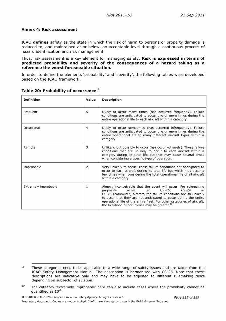
NPA 2011-16 21 Sep 2011
TE.RPRO.00034-002© European Aviation Safety Agency. All rights reserved.
Proprietary document. Copies are not controlled. Confirm revision status through the EASA-Internet/Intranet.
Page 225 of 239
Annex 4: Risk assessment
ICAO defines safety as the state in which the risk of harm to persons or property damage is
reduced to, and maintained at or below, an acceptable level through a continuous process of
hazard identification and risk management.
Thus, risk assessment is a key element for managing safety. Risk is expressed in terms of
predicted probability and severity of the consequences of a hazard taking as a
reference the worst foreseeable situation.
In order to define the elements ‘probability’ and ‘severity’, the following tables were developed
based on the ICAO framework.
Table 20: Probability of occurrence19
Definition Value Description
Frequent 5 Likely to occur many times (has occurred frequently). Failure conditions are anticipated to occur one or more times during the entire operational life to each aircraft within a category.
Occasional 4 Likely to occur sometimes (has occurred infrequently). Failure conditions are anticipated to occur one or more times during the entire operational life to many different aircraft types within a category.
Remote 3 Unlikely, but possible to occur (has occurred rarely). Those failure conditions that are unlikely to occur to each aircraft within a category during its total life but that may occur several times when considering a specific type of operation.
Improbable 2 Very unlikely to occur. Those failure conditions not anticipated to occur to each aircraft during its total life but which may occur a few times when considering the total operational life of all aircraft within a category.
Extremely improbable 1 Almost inconceivable that the event will occur. For rulemaking proposals aimed at CS-25, CS-29 or CS-23 (commuter) aircraft, the failure conditions are so unlikely to occur that they are not anticipated to occur during the entire
operational life of the entire fleet. For other categories of aircraft, the likelihood of occurrence may be greater.20
19 These categories need to be applicable to a wide range of safety issues and are taken from the
ICAO Safety Management Manual. The description is harmonised with CS-25. Note that these descriptions are indicative only and may have to be adjusted to different rulemaking tasks
depending on subsector of aviation.
20 The category ‘extremely improbable’ here can also include cases where the probability cannot be
quantified as 10-9.
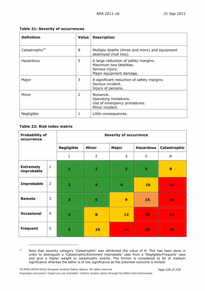
NPA 2011-16 21 Sep 2011
TE.RPRO.00034-002© European Aviation Safety Agency. All rights reserved.
Proprietary document. Copies are not controlled. Confirm revision status through the EASA-Internet/Intranet.
Page 226 of 239
Table 21: Severity of occurrences
Definition Value Description
Catastrophic21 8 Multiple deaths (three and more) and equipment
destroyed (hull loss).
Hazardous 5 A large reduction of safety margins.
Maximum two fatalities.
Serious injury.
Major equipment damage.
Major 3 A significant reduction of safety margins.
Serious incident.
Injury of persons.
Minor 2 Nuisance.
Operating limitations.
Use of emergency procedures.
Minor incident.
Negligible 1 Little consequences.
Table 22: Risk index matrix
Probability of
occurrence
Severity of occurrence
Negligible Minor Major Hazardous Catastrophic
1 2 3 5 8
Extremely
improbable
1 1 2 3 5 8
Improbable 2 2 4 6 10 16
Remote 3 3 6 9 15 24
Occasional 4 4 8 12 20 32
Frequent 5 5 10 15 25 40
21 Note that severity category ‘Catastrophic’ was attributed the value of 8. This has been done in
order to distinguish a ‘Catastrophic/Extremely improbable’ case from a ‘Negligible/Frequent’ case
and give a higher weight to catastrophic events. The former is considered to be of medium significance whereas the latter is of low significance as the potential outcome is limited.
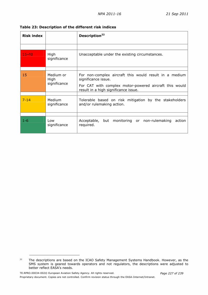
NPA 2011-16 21 Sep 2011
TE.RPRO.00034-002© European Aviation Safety Agency. All rights reserved.
Proprietary document. Copies are not controlled. Confirm revision status through the EASA-Internet/Intranet.
Page 227 of 239
Table 23: Description of the different risk indices
Risk index Description22
15-40 High
significance
Unacceptable under the existing circumstances.
15 Medium or
High
significance
For non-complex aircraft this would result in a medium
significance issue.
For CAT with complex motor-powered aircraft this would
result in a high significance issue.
7-14 Medium
significance
Tolerable based on risk mitigation by the stakeholders
and/or rulemaking action.
1-6 Low
significance
Acceptable, but monitoring or non-rulemaking action
required.
22 The descriptions are based on the ICAO Safety Management Systems Handbook. However, as the
SMS system is geared towards operators and not regulators, the descriptions were adjusted to better reflect EASA’s needs.

NPA 2011-16 21 Sep 2011
TE.RPRO.00034-002© European Aviation Safety Agency. All rights reserved.
Proprietary document. Copies are not controlled. Confirm revision status through the EASA-Internet/Intranet.
Page 228 of 239
II. Regulatory Impact Assessment for the sailplane cloud flying rating
Table of Contents
1 PROCESS AND CONSULTATION ....................................................................... 229
2 ISSUE ANALYSIS AND RISK ASSESSMENT ....................................................... 229
2.1 WHAT IS THE ISSUE AND WHO IS AFFECTED? ............................................................ 229
2.2 WHAT ARE THE RISKS (PROBABILITY AND SEVERITY)? .................................................. 231
3 OBJECTIVES .................................................................................................... 231
4 IDENTIFICATION OF OPTIONS ........................................................................ 231
5 METHODOLOGY AND DATA REQUIREMENTS .................................................... 232
5.1 APPLIED METHODOLOGY: MULTI-CRITERIA ANALYSIS ................................................... 232
6 ANALYSIS OF IMPACTS ................................................................................... 234
6.1 SAFETY IMPACT ............................................................................................... 234
6.2 ENVIRONMENTAL IMPACT ...................................................................................... 234
6.2 ECONOMIC IMPACT ........................................................................................... 235
6.3 SOCIAL IMPACT............................................................................................... 235
6.5. PROPORTIONALITY ............................................................................................ 236
6.4 REGULATORY HARMONIZATION (INCLUDING ATC & ICAO REQUIREMENTS)......................... 236
7. CONCLUSION AND PREFERRED OPTION .......................................................... 237
ANNEX 1: TABLES ................................................................................................... 238

NPA 2011-16 21 Sep 2011
TE.RPRO.00034-002© European Aviation Safety Agency. All rights reserved.
Proprietary document. Copies are not controlled. Confirm revision status through the EASA-Internet/Intranet.
Page 229 of 239
1 Process and consultation
With the adoption of Regulation 216/2008 the European legislator decided to move the safety
requirements for Flight Crew Licencing (FCL) to the European level. The remit of the Agency
was therefore expanded to cover FCL. During the subsequent development of European
requirements for sailplanes, the Agency discussed in the responsible rulemaking group
FCL.001 the need for additional ratings. Member States were contacted as well in order to
evaluate the actual situation and to identify which national ratings should be transferred to a
European level. Based on the input received, the Agency decided to develop initially additional
ratings for aerobatics, towing, night-flying, mountain-flying and for test flights. The issue of a
cloud flying rating for sailplane pilots was raised in this group, but it was decided to develop
such a rating in a separate rulemaking task dealing also with qualifications for aeroplane pilots
to fly in IMC or under IFR.
Consequently, rulemaking task FCL.008 was created with experts from NAAs, flight crew
organisations, training organisations as well as the general aviation community. The
assessment of a potential cloud flying rating was identified as one of the group’s main tasks.
The kick-off meeting was held in December 2008. The present RIA analyses the proposals
developed by the group and is based on inputs and comments provided by the group.
2 Issue Analysis and risk assessment
2.1 What is the issue and who is affected?
In order to analyse the underlying issue and reasoning for a potential cloud flying rating for
sailplanes, it is important first to briefly describe the relevant ICAO rules of the air as well as
Part-FCL and to describe certain specifics of sailplane operations.
Airspace structure and rules of the air
Annex 2 to the International Convention on International Civil Aviation (‘ICAO Convention’)
defines certain visibility and distance-from-cloud minima in Visual Meteorological Conditions
(VMC) in order to ensure aviation safety. These limits are defined for specific altitude bands
and airspace classes (see Annex Table 27). In airspace classes F and G (uncontrolled
airspace), at or below 900 m (3 000 ft) AMSL or 300 m (1 000 ft) above terrain, whichever is
higher, it is allowed to fly ‘clear of cloud’, i.e. with no minimal separation between cloud and
aircraft. In all other airspace classes and above 900 m AMSL, a minimum distance from cloud
is prescribed: 300 m (1 000 ft) vertically and 1 500 m horizontally.
These fundamental rules apply to all airspace users, including sailplanes, and provide a crucial
level of protection for all airspace users by avoiding mid-air collisions near clouds.
As a consequence of these ICAO rules, pilots of sailplanes might, under certain weather
conditions and in specific airspace categories, be forced to fly only in relatively low altitudes.
This has a direct negative impact on the operational range of sailplanes and will be explained
in more detail below.
The operational range of sailplanes
As long as sailplanes are limited to operate under VMC, the upper limit of the sailplane
operational band is defined by the altitude of the cloud base in conjunction with the above
ICAO rules of the air.
NPA 2011-16 21 Sep 2011
TE.RPRO.00034-002© European Aviation Safety Agency. All rights reserved.
Proprietary document. Copies are not controlled. Confirm revision status through the EASA-Internet/Intranet.
Page 230 of 239
The base of convective clouds varies from hour to hour, from day to day and across Europe.
VMC can be maintained up to the base of the cloud when it is no higher than 900 m (3 000 ft)
above mean sea level (AMSL). Above that altitude ICAO rules of the air require a 300 m
(1 000 ft) vertical separation from cloud. Sailplanes may thus climb in uncontrolled airspace no
higher than 900 m (3 000 ft) AMSL unless the cloud base is 1 200 m (4 000 ft) AMSL or more.
The bottom level of a sailplane’s operating band is defined by the start of landing preparations,
generally 300 m (1 000 ft) above ground level (AGL), typically 450 m (1 500 ft) AMSL over
much of Europe depending on the orographic situation and the experience of the pilot.
Therefore, when operating under VMC, sailplane pilots in Europe typically are limited to
operate between 900 m (3 000 ft) AMSL and 450 m (1 500 ft) AMSL unless the cloud base is
4 000 ft or more. This operating layer permits only an 18km radius of action for a sailplane
with a typical 1:40 glide ratio.
In contrast, if flights in IMC and in clouds were possible, a sailplane that climbs to cloud base
and enters a cloud in order to climb up to 1 500 m (5 000 ft) enjoys a 1 060 m (3 500 ft)
operating layer and therefore a 40km radius of action. This greater radius of action means a
much greater operating area. The increase in operating area allows the pilot finding the next
thermal, routing to avoid airspace or choosing an area with suitable out-landing opportunities.
Flights within cloud are relatively rare but the much stronger updrafts involved present
opportunities for increasing the operating radius of the sailplane and thus options available for
continuing a safe flight with reduced risk of an out-landing. These stronger updrafts also mean
that the clouds suitable for sailplane climbs are normally avoided by other aviators.
Exploitation of the lee wave flows which occur downwind of hills and mountains forms a
significant part of sailplane flying in most Member States. This updraft is generally exploited in
VMC, far above any cloud layers, but climbs to, and descents from these areas often needs
flight within 1 500 m horizontally from cloud or entering a cloud for a short time period only.
For the above reasons, an option to allow cloud flying could significantly widen the operational
range of sailplanes.
Current situation in Member States
Current regulations vary between Member States. Some have a restriction on sailplanes flying
in IMC or in clouds and some permit it within specified areas. The UK, notably, allows flying in
IMC and in clouds. Member States permitting flights in IMC or in cloud within specified airspace
categories are: the Czech Republic, Finland, Germany, Norway, Poland, Sweden and
Switzerland. This is managed, usually through a specific rating. All other Member States do not
allow sailplanes to fly in IMC/clouds.
The Agency proposals for Part-FCL, as published in Opinion 04/201023, currently do not foresee
a cloud flying rating for sailplanes.
The European Commission24 estimates that there were about 22 000 gliders and 90 000
licensed glider pilots in Europe in 2006. These pilots flew more than 1.5 million hours in 2009.
23 Opinion of the European Aviation Safety Agency of 26 August 2010 for a draft Commission Regulation XXX/2010
laying down Implementing Rules for Pilot Licensing. Available at: http://www.easa.europa.eu/agency-measures/opinions.php. Adoption by the Commission through the ‘Comitology’ process expected for the last quarter 2011.
24 European Commission (2007): General Aviation in the European Community. Discussion Paper. Directorate General Energy and Transport, Directorate F – Air Transport. Brussels, 1 February 2007, p9. Available at http://ec.europa.eu/transport/air_portal/internal_market/doc/general_av_discussion_paper.pdf.

NPA 2011-16 21 Sep 2011
TE.RPRO.00034-002© European Aviation Safety Agency. All rights reserved.
Proprietary document. Copies are not controlled. Confirm revision status through the EASA-Internet/Intranet.
Page 231 of 239
2.2 What are the risks (probability and severity)?
According to the ECCAIRS data base, between 2001 and 2010, there were 37 mid-air collisions
in EASA States involving sailplanes. In many reports the narrative is very sketchy and data
about the weather is missing in 15 cases; information about clouds is missing in 21 cases. In
the information available, there are no instances of collision in clouds, however at least two
cases have been in the ‘proximity to clouds’ with one fatality each. These cases were recorded
in 2004 and 2006. No information on a cloud flying rating was provided for those cases.
3 Objectives
The specific objective for this task is to facilitate sailplane operations by increasing the
operating range of sailplanes by allowing them to operate in clouds or in IMC conditions while
maintaining a uniform high level of safety, taking into account the rules for the specific
airspace categories and the Air Traffic Control (ATC) requirements regarding such flights.
4 Identification of options
The following options were identified during the work of rulemaking group FCL.008 in order to
achieve the above objective.
Option 0
No regulatory change to Part-FCL. As proposed in Opinion 04/2010, this option does not
foresee a cloud flying rating.
Option 1
A sailplane cloud flying rating would be added to Part-FCL Subpart I ‘Additional Ratings’.
The privileges of this rating would allow flying in clouds if airspace structure and
regulations as well as additional national regulation allow. Requirements for the rating
are: a licence holder must have completed at least 30 hours as PIC on sailplanes;
Training course at an ATO including theoretical knowledge instruction and 5 hours of dual
instruction controlling the sailplane solely by reference to instruments has to be
completed;
Skill test with a flight examiner (FE) has to be passed;
Every 24 months the rating has to be revalidated by passing a specific proficiency check.
Option 2
A Restricted Sailplane Cloud Flying Rating (SCFR-R) would be introduced for flight in IMC clear
of cloud if permitted by the airspace structure and regulations as well as under national law.
Requirements for the rating are:
No specific experience on sailplanes after licence issue required;
Theoretical instruction provided by an instructor;
No specific skill test.
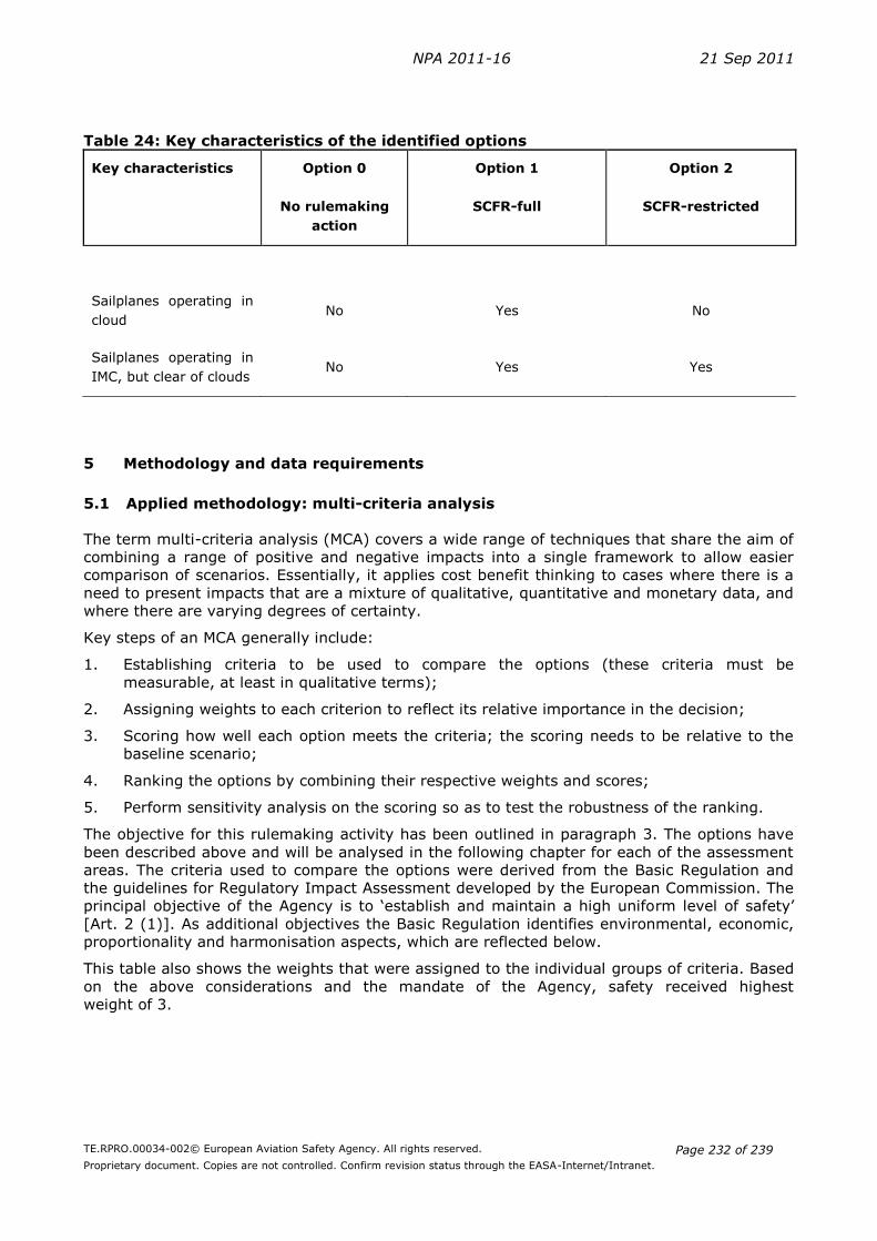
NPA 2011-16 21 Sep 2011
TE.RPRO.00034-002© European Aviation Safety Agency. All rights reserved.
Proprietary document. Copies are not controlled. Confirm revision status through the EASA-Internet/Intranet.
Page 232 of 239
Table 24: Key characteristics of the identified options
Key characteristics Option 0 Option 1 Option 2
No rulemaking
action
SCFR-full SCFR-restricted
Sailplanes operating in
cloud No Yes No
Sailplanes operating in
IMC, but clear of clouds No Yes Yes
5 Methodology and data requirements
5.1 Applied methodology: multi-criteria analysis
The term multi-criteria analysis (MCA) covers a wide range of techniques that share the aim of
combining a range of positive and negative impacts into a single framework to allow easier
comparison of scenarios. Essentially, it applies cost benefit thinking to cases where there is a
need to present impacts that are a mixture of qualitative, quantitative and monetary data, and
where there are varying degrees of certainty.
Key steps of an MCA generally include:
1. Establishing criteria to be used to compare the options (these criteria must be
measurable, at least in qualitative terms);
2. Assigning weights to each criterion to reflect its relative importance in the decision;
3. Scoring how well each option meets the criteria; the scoring needs to be relative to the
baseline scenario;
4. Ranking the options by combining their respective weights and scores;
5. Perform sensitivity analysis on the scoring so as to test the robustness of the ranking.
The objective for this rulemaking activity has been outlined in paragraph 3. The options have
been described above and will be analysed in the following chapter for each of the assessment
areas. The criteria used to compare the options were derived from the Basic Regulation and
the guidelines for Regulatory Impact Assessment developed by the European Commission. The
principal objective of the Agency is to ‘establish and maintain a high uniform level of safety’
[Art. 2 (1)]. As additional objectives the Basic Regulation identifies environmental, economic,
proportionality and harmonisation aspects, which are reflected below.
This table also shows the weights that were assigned to the individual groups of criteria. Based
on the above considerations and the mandate of the Agency, safety received highest
weight of 3.

NPA 2011-16 21 Sep 2011
TE.RPRO.00034-002© European Aviation Safety Agency. All rights reserved.
Proprietary document. Copies are not controlled. Confirm revision status through the EASA-Internet/Intranet.
Page 233 of 239
Table 25: Assessment criteria for the Multi-Criteria Analysis
Environmental impacts are attributed with a weight of 2 as the Agency has certain specific
responsibilities in this area related to noise and emissions. For the same reason impacts on the
other assessment areas are attributed with a weight of 1 since these areas are to be duly
considered when developing the implementing rules. Each option developed below will be
assessed based on the above criteria. Scores are used to show the degree to which each of the
options achieves the assessment criteria. The scoring is performed on a scale between -5 and
+5.Table 8 gives an overview of the scores and their interpretation.
Table 26: Scores for the Multi-criteria analysis
Score Descriptions Example for scoring options
+5 Highly positive impact Highly positive safety, social or environmental protection impact. Savings of more than 5% of annual turnover for any single firm; Total annual savings of more than 100 million euros
+3 Medium positive impact Medium positive social, safety or environmental protection impact. Savings of 1% - 5% of annual turnover for any single firm; Total
annual savings of 10-100 million euros
+1 Low positive impact Low positive safety, social or environmental protection impact. Savings of less than 1% of annual turnover for any single firm; Total annual savings of less than 10 million euros
0 No impact
-1 Low negative impact Low negative safety, social or environmental protection impact. Costs of less than 1% of annual turnover for any single firm; Total annual costs of less than 10 million euros
-3 Medium negative impact Medium negative safety, social or environmental protection impact. Costs of 1% - 5% of annual turnover for any single firm; Total annual costs of 10-100 million euros
Weight Description
Safety 3 Maintain or improve the level of safety
1 Facilitate sailplane operations Ensure ‘level playing field’
Environment 2 Avoid negative effects on the environment
Social 1 Avoid negative effects on employment in aviation Promote high quality jobs in the private sector for aviation
Equality and proportionality
1 Ensure proportionate rules for Small and Medium sized Enterprises (SMEs)/General Aviation/Business Aviation
Regulatory harmonisation
1 Ensure full consistency with EU laws and regulations Ensure compliance with ICAO standards (if appropriate) Achieve the maximum appropriate degree of harmonisation with the FAA/TCCA equivalent rules for commercial aviation
Overall Objectives Specific Objectives and assessment criteria
Economic

NPA 2011-16 21 Sep 2011
TE.RPRO.00034-002© European Aviation Safety Agency. All rights reserved.
Proprietary document. Copies are not controlled. Confirm revision status through the EASA-Internet/Intranet.
Page 234 of 239
-5 Highly negative impact Highly negative safety, social or environmental protection impact. Costs of more than 5% of annual turnover for any single firm; Total annual costs of more than 100 million euros
6 Analysis of impacts
This section discusses the impact of the three options described above as regards the Agency’s
main assessment criteria: safety, environmental and economic impact as well as social and
regulatory harmonisation issues.
As the proposed rules will for the first time introduce harmonised requirements and privileges
for cloud flying across all Member States, the impact on a particular EASA Member State will
depend on the current national rules. As described above, there are currently eight EASA
Member States (CZ, DE, FI, NO, PL, UK, SE, CH) which in some form allow cloud/IMC flying for
sailplanes. 23 Member States do not foresee such a possibility.
6.1 Safety impact
In the eight EASA Member States where cloud flying and flights in IMC are permitted,
sailplanes currently make use of airspace that would otherwise not be accessible for sailplane
operations. Option 0 would discontinue this practice thereby reducing sailplanes operational
range.
This reduction in range may be expected to increase the number of off-airfield landings which
carry significant risks. The European Gliding Union (EGU) also pointed out that in this case
pilots may spend more time assessing and choosing possible landing areas, thereby reducing
the attention they can give to collision avoidance. Option 0 is therefore expected to have a low
negative safety impact (MCA score -1).
Option 1 introduces a harmonised cloud flying rating across all EASA Member States. For the
eight Member States with a similar arrangement at present, this would have no impact on
safety. In the Member States where such a rating is not yet in place, it is expected to have a
positive safety impact because it would widen the operating range for sailplanes.
Consequently, the risk of out-landings is reduced. Option 1 is therefore expected to induce a
low positive safety impact (MCA score +1).
The introduction of the SCFR-restricted, as proposed in option 2, would also provide additional
operating range and thus could be expected to lower the risk of out-landings, albeit somewhat
less than option 1 with a full cloud flying rating.
However, this option would provide an alternative implementation to the provisions in Annex 2
of the Chicago Convention and may not be in line with airspace regulations or Air Traffic
Management procedures in certain Member States.
Option 2 is therefore overall expected to have a neutral safety impact (MCA score 0).
6.2 Environmental impact
Any change in sailplane activity will have a corresponding impact on greenhouse gas emissions
as in a certain amount of sailplane operations the launch methods aerotow or self-launch are
used. However, the overall impact of sailplane operations is a very small fraction of aviation
emissions. Any change identified as an effect of this NPA is thus considered negligible (MCA
score 0).
NPA 2011-16 21 Sep 2011
TE.RPRO.00034-002© European Aviation Safety Agency. All rights reserved.
Proprietary document. Copies are not controlled. Confirm revision status through the EASA-Internet/Intranet.
Page 235 of 239
6.2 Economic impact
The proposed requirements in option 0 (Part-FCL unchanged) do not contain a specific cloud
flying qualification. This will lead to a situation where sailplane pilots will not be allowed to fly
in clouds or in IMC in any EASA Member States. Consequently, a certain part of sailplane
activities that currently take place across the eight Member States with such qualifications
would have to be discontinued.
The resulting negative economic impact would vary across Europe. In the Member States
without a cloud flying rating or with good weather conditions for sailplane operations no impact
would be expected. On the other hand, sailplane pilots in the eight Member States currently
allowing sailplane IMC flights and/or flights in clouds would be negatively impacted.
A survey of chairpersons of UK gliding clubs25 indicated that this option could lead to an 82.3%
reduction in activity in the UK. Research26 estimates that the total contribution of gliding to the
UK economy is €23.3 million per annum. The potential negative economic impact would thus
amount to €19.2 million.
The Agency considers this a high estimate, which can certainly not be extrapolated to all EASA
Member States. For all EASA Member States the reduction in activity is more likely to be in the
order of less than 10%. This estimate is based on the fact that 23 EASA Member States
currently do not allow cloud flying and in some of the cloud flying countries the actual use of
this possibility is not known with certainty. Overall, given that a common practice in eight
Member States would need to be discontinued, option 0 is expected to create a medium
negative economic impact (MCA score -3).
As regards option 1 (‘full cloud flying rating’), there would be no significant change to current
arrangements for clubs and pilots in the Member States having such a rating in place today.
For the other Member States the Agency expects a low positive economic impact as the
operational range of sailplanes is potentially increased. The estimate is ‘low’, because it is not
clear to what extend the new possibility will be used in practice (MCA score +1).
Option 2 creates a restricted rating, not allowing sailplanes to fly in cloud, but only up to the
base of the cloud in IMC. It will therefore reduce gliding activity in the eight EASA Member
States where currently a full cloud flying rating exists.
The economic impact will be less significant than for option 0. In countries where no rating
exists, a certain amount of pilots will take up the training for this rating. The Agency does not
have sufficient data to estimate the overall economic impact, but as there are positive effects
for some countries and negative effects for others, it is assumed that the overall impact across
Europe will be neutral (MCA score 0).
6.3 Social impact
Across the EU27+4, sailplane flying is largely organised within voluntary clubs, with a small
number of professional organisations offering services to this predominantly volunteer body. It
is difficult to measure the social benefits in this context, but both the flying and associated
ground based club activities certainly offer opportunities for personal development and social
interaction. Young people are offered opportunities to start flying at relatively low costs and
thus sailplane flying can act as an important entry point to aviation.
25
British Gliding Association (2009): Report On A Survey Of The Estimated Impact Of IMC Options For
Glider Flying. Leicester. 26
Lober, T (2004): General Aviation Small Aerodrome Research Study. The National Pilot Survey. The
Bartlett School, University College London. August 2004. Available at http://www.gaac.org.uk/gasar/GASAR_NationalPilotSurvey.pdf.

NPA 2011-16 21 Sep 2011
TE.RPRO.00034-002© European Aviation Safety Agency. All rights reserved.
Proprietary document. Copies are not controlled. Confirm revision status through the EASA-Internet/Intranet.
Page 236 of 239
The reduction in sailplane activity expected for option 0 would thus translate also in a low
negative social impact (MCA score -1).
Accordingly, option 1 can be expected to have positive social implications as the level of
sailplane activity is expected to increase across Europe (MCA score +1).
Option 2 would overall have no social impact as the change in activity across Europe is
expected to be negligible (MCA score 0).
6.5. Proportionality
The economic impacts described above are largely impacting small scale activities. Any
negative economic impact will induce an over proportionate burden on gliding clubs and
related activities. Therefore the same scores are attributed as for the economic impact: Option
0 (-3), Option 1 (1) and Option 2 (0).
6.4 Regulatory harmonization (including ATC & ICAO requirements)
Option 0 would discontinue current practice of flying in IMC and clouds in eight Member
States. Established ATC procedures could be abolished and the coordination between ATC and
the sailplane pilots for this kind of flights would no longer be necessary. Therefore, a positive
impact on ATC workload could be expected, albeit at an extremely limited range. As there is no
specific cloud flying rating for sailplanes foreseen in ICAO, a harmonisation problem does not
exist at this level (MCA score 0).
Option 1 introduces a cloud flying rating across Europe. For the eight Member States where
such a rating exists, ATC workload would remain unchanged. In the other states ATC would
need to introduce new procedures accordingly. This is considered a low negative impact (MCA
score -1).
Option 2 ‘restricted Sailplane Cloud Flying Rating’ introduces a new rating for all Member
States except one. The impact on ATC workload is considered equivalent to option 1, i.e. a low
negative impact (MCA score -1).
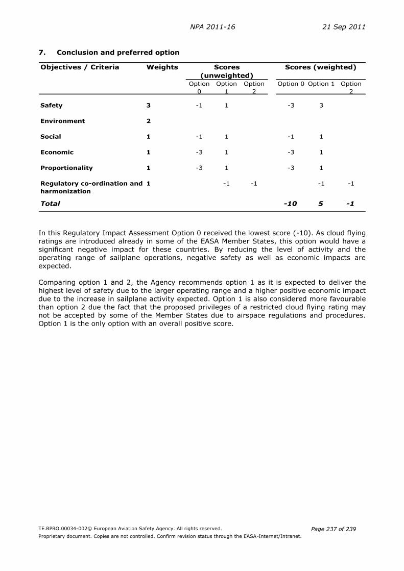
NPA 2011-16 21 Sep 2011
TE.RPRO.00034-002© European Aviation Safety Agency. All rights reserved.
Proprietary document. Copies are not controlled. Confirm revision status through the EASA-Internet/Intranet.
Page 237 of 239
7. Conclusion and preferred option
Objectives / Criteria Weights
Option
0
Option
1
Option
2
Option 0 Option 1 Option
2
Safety 3 -1 1 -3 3
Environment 2
Social 1 -1 1 -1 1
Economic 1 -3 1 -3 1
Proportionality 1 -3 1 -3 1
Regulatory co-ordination and
harmonization
1 -1 -1 -1 -1
Total -10 5 -1
Scores
(unweighted)
Scores (weighted)
In this Regulatory Impact Assessment Option 0 received the lowest score (-10). As cloud flying
ratings are introduced already in some of the EASA Member States, this option would have a
significant negative impact for these countries. By reducing the level of activity and the
operating range of sailplane operations, negative safety as well as economic impacts are
expected.
Comparing option 1 and 2, the Agency recommends option 1 as it is expected to deliver the
highest level of safety due to the larger operating range and a higher positive economic impact
due to the increase in sailplane activity expected. Option 1 is also considered more favourable
than option 2 due the fact that the proposed privileges of a restricted cloud flying rating may
not be accepted by some of the Member States due to airspace regulations and procedures.
Option 1 is the only option with an overall positive score.
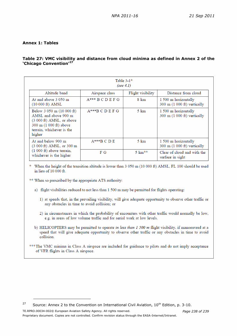
NPA 2011-16 21 Sep 2011
TE.RPRO.00034-002© European Aviation Safety Agency. All rights reserved.
Proprietary document. Copies are not controlled. Confirm revision status through the EASA-Internet/Intranet.
Page 238 of 239
Annex 1: Tables
Table 27: VMC visibility and distance from cloud minima as defined in Annex 2 of the
‘Chicago Convention’27
27
Source: Annex 2 to the Convention on International Civil Aviation, 10th Edition, p. 3-10.

NPA 2011-16 21 Sep 2011
TE.RPRO.00034-002© European Aviation Safety Agency. All rights reserved.
Proprietary document. Copies are not controlled. Confirm revision status through the EASA-Internet/Intranet.
Page 239 of 239
Table 28: ATS airspace classes as defined in Annex 11 of the ‘Chicago Convention’28
28
Source: Annex 11 to the Convention on International Civil Aviation, 13th Edition, p. APP 4-1.