NOx Control & Technology for an Equipment … Bedi, Doosan, Cranfield, 10...NOx Control & Technology...
19
NOx Control & Technology for an Equipment Manufacturer CRF, Cranfield, 10 April 2013
Transcript of NOx Control & Technology for an Equipment … Bedi, Doosan, Cranfield, 10...NOx Control & Technology...

NOx Control & Technology for an Equipment ManufacturerCRF, Cranfield, 10 April 2013

1
NOx Technologies
In-furnace combustion technologies:
Low NOx Burners (LNB’s)
Advanced LNB’s (aLNB’s)
Overfire Air (OFA)
Boosted Overfire Air (BOFA)
Reburn
Post-combustion technologies:
Selective Non-Catalytic Reduction (SNCR)
Selective Catalytic Reduction (SCR)– Full SCR
– Optimised SCR1
2
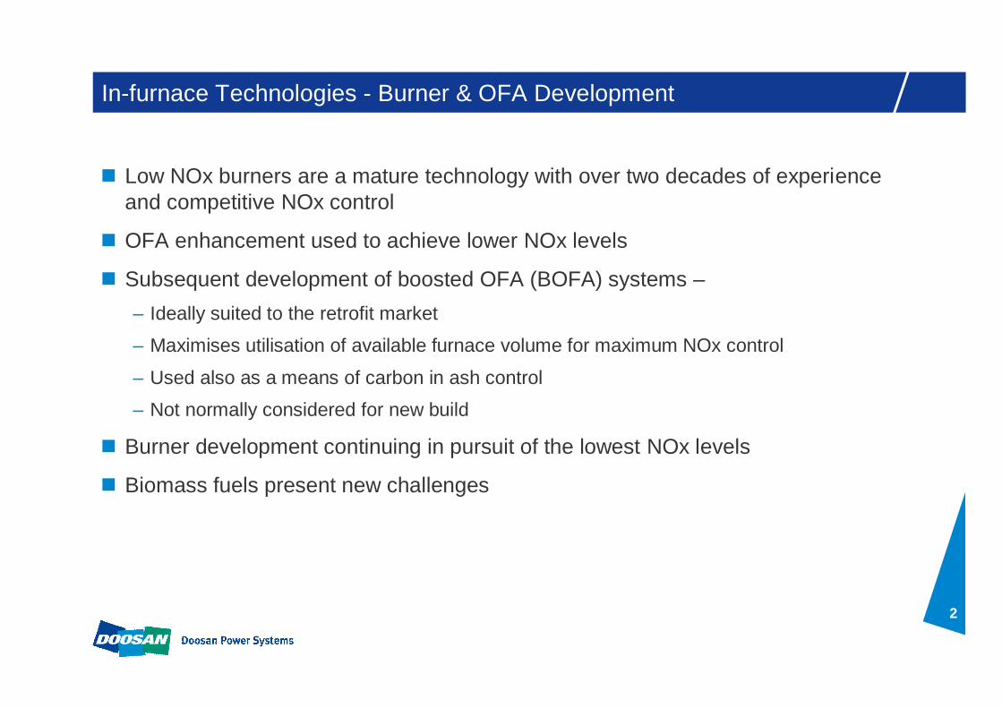
In-furnace Technologies - Burner & OFA Development
Low NOx burners are a mature technology with over two decades of experience and competitive NOx control
OFA enhancement used to achieve lower NOx levels
Subsequent development of boosted OFA (BOFA) systems –– Ideally suited to the retrofit market
– Maximises utilisation of available furnace volume for maximum NOx control
– Used also as a means of carbon in ash control
– Not normally considered for new build
Burner development continuing in pursuit of the lowest NOx levels
Biomass fuels present new challenges
3
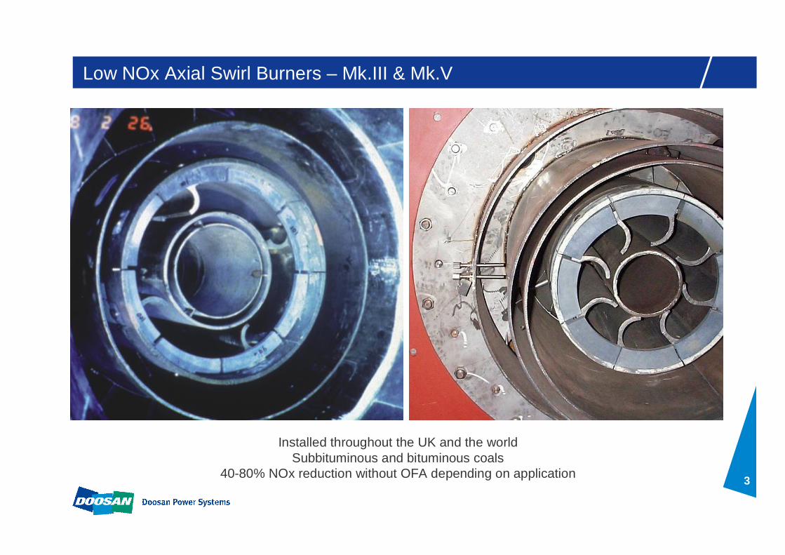
Low NOx Axial Swirl Burners – Mk.III & Mk.V
Installed throughout the UK and the worldSubbituminous and bituminous coals
40-80% NOx reduction without OFA depending on application
4
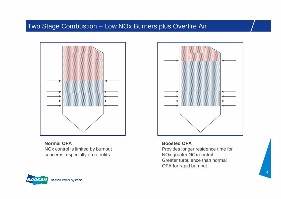
Two Stage Combustion – Low NOx Burners plus Overfire Air
Normal OFANOx control is limited by burnout concerns, especially on retrofits
Boosted OFA Provides longer residence time for NOx greater NOx controlGreater turbulence than normal OFA for rapid burnout

5
Installation of BOFA technology to satisfyEU Large Combustion Plant Directive NOx requirement
of 500 mg/Nm3 for existing plant by 2008
Project Profile – Drax Unit 1

6
NOx Reduction History
Carbon target
NOx target
0
200
400
600
800
1000
1200
1400
Pre-LNBs LNBs LNBs + BOFA
ID F
an O
utle
t NO x
(mg/
Nm
3@
6%
O2)
0
2
4
6
8
10
12
14
Car
bon
in A
sh (%
)
NOxCIA
Project Profile – Drax Unit 1
NOx target

7
Mk.III Experience with Dried Lignite
In the large-scale test facility, changes to primary air velocity thro’ PA tube annulus enlargement had a dramatic effect on flame front. This principle of PA velocity reduction was adopted for 100% biomass firing.
High Velocity Low Velocity
8
Biomass Firing on Mk.III
To promote early ignition and ensure flame stability on 100% biomass firing the following modifications have been successfully demonstrated on the Mk.IIIburner.
Reduced PA velocity.
Removal of fuel collectors to enable the swirling motion of the fuel jet generated by the inlet scroll to continue to the PA tube exit.
Combination of SA and TA streams into a single air stream (swirled) has also been proven to further enhance flame stability.
9
0.5
0.6
0.7
0.8
0.9
1
1.1
1 1.2 1.4 1.6 1.8 2 2.2 2.4
Fuel Type (Fuel Ratio)
NO
x(R
elat
ive)
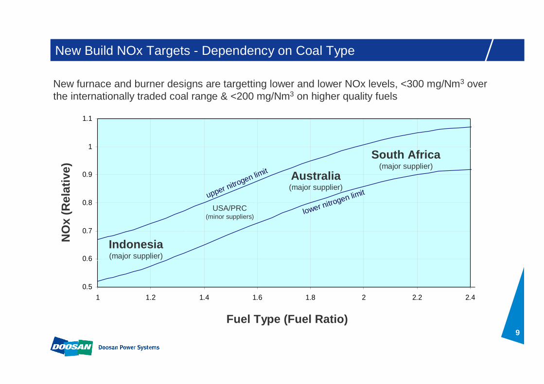
South Africa(major supplier)
Australia(major supplier)
Indonesia(major supplier)
USA/PRC(minor suppliers)
lower nitrogen limitupper nitrogen limit
New Build NOx Targets - Dependency on Coal Type
New furnace and burner designs are targetting lower and lower NOx levels, <300 mg/Nm3 over the internationally traded coal range & <200 mg/Nm3 on higher quality fuels

10
D-NOx Burner – The Next Generation
Developed 2007 to 2011– Stage 1: Pilot scale 2.2MWt Burner Testing (Mar –Apr 2008)– Stage 2: Full scale 63MWt Burner Testing (Oct – Dec 2008)– Stage 3: Full scale 40 MW t D-NOxTM / Mk.III Comparison (Sept – Nov 2009)– Stage 4: Drax Integrity Demonstration (Jun 2010)– Stage 5: Castle Peak B installation (Jun 2011)
Design features– Axial flow PA with reduced number of high wear components– CFD-designed PA tube– New flameholder
Performance– Up to 25% NOx improvement over Mk.III two-stage performance– No change to carbon in ash

11
D-NOx – Development Stage 1
2.2 MWt Burner Testing (March - April ‘08)
Changwon 3MWt Test Facility
Selection of swirl, flameholder, coal distributor and air split configurations

12
D-NOx – Development Stage 2
Furnace & overfire air ports
Fuel bin and feed system
Secondary air supplyand heater
Primary air supplyand heater
63MWt Burner Testing (October ‘08 – April ‘09)
Testing on the Clean Combustion Test Facility carried out at λ 0.8.
13
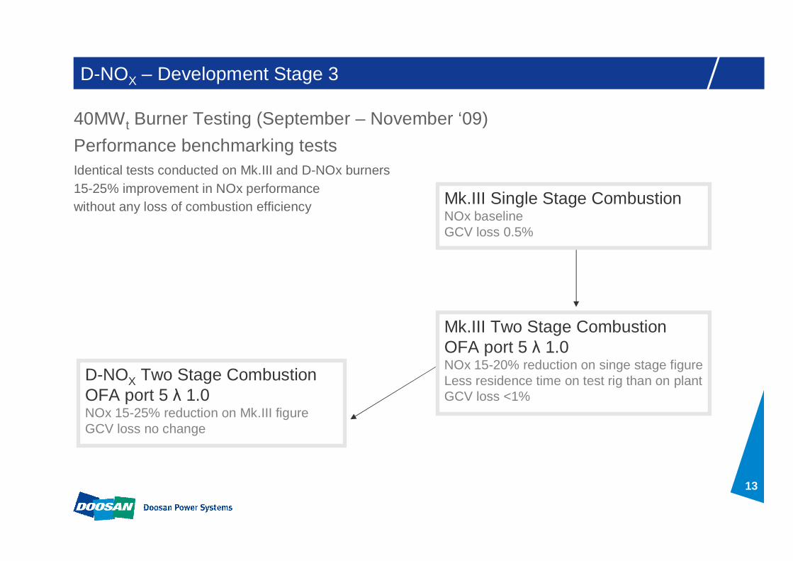
D-NOX – Development Stage 3
13
40MWt Burner Testing (September – November ‘09)
D-NOX Two Stage CombustionOFA port 5 λ 1.0NOx 15-25% reduction on Mk.III figureGCV loss no change
Mk.III Two Stage CombustionOFA port 5 λ 1.0NOx 15-20% reduction on singe stage figureLess residence time on test rig than on plantGCV loss <1%
Mk.III Single Stage CombustionNOx baselineGCV loss 0.5%
Performance benchmarking testsIdentical tests conducted on Mk.III and D-NOx burners 15-25% improvement in NOx performance without any loss of combustion efficiency

14
D-NOX – Development Stage 4
Two burners installed on lower and top rear rowsof 660 MWe unit
Burners operational from June 2010
Aims:– Investigate burner integrity and wear
– Demonstrate oil ignition system
– Verify CRAC3D modelling
Progress:– Remote IR flame monitor successfully trialled
– Permanent IR flame monitoring system successfully installed
– Measured component temperatures within modelling range
Plan:– Remove PA cartridge to allow inspection against wear and deformation
41MWt Burner Installation (Jun ’10 to present) Integrity Demonstration

15
D-NOX – Development Stage 5
Project Scope– 18 D-NOx Burners installed on 680MWe unit during March / April 2011 outage
– Partial retrofit, top 2 rows front and top row rear
– Designed for two stage combustion and a stoichiometry of 0.9
– Additional BOFA ports opened up to allow for the deeper staging
Performance – Indonesian coal 188 mg/Nm3, Australian coal 298 mg/Nm3
– Back-to-back NOx reduction of 19-22%
– Carbon in ash <1-2% (no change), CO negligible
– Burner turndown demonstrated at 45 % load without oil support
42MWt Burner Installation (March/April 2011) Plant Installation

16
D-NOx Burner – Continuing Development Test Rig Performance
0
50
100
150
200
250
300
3 4 5 6 7
OFA Port
NO
x pp
m (c
orre
cted
)
25/50/5025/50/505/50/505/63/3725/50/505/50/50
63 MWt burner design, South African coal
NOx target of 300 mg/Nm3
has been achieved in the test rigOFA port 6 performance can be replicated on plant

17
Performance – Furnace Design Influence
Korea 2013870 MWe
NOx 310 mg/Nm33.5% carbon in ash
Internationallytraded coal
D-NOx burners42 x 66 MWt
Dual OFA for newbuild application
UK 1970s660 MWe
NOx 450 mg/Nm36% carbon in ash
UK coal
Mk.III burners60 x 41 MWt
Boosted OFA forretrofit application
1488oC
1.62 secs
0.43 secs
1.29 MW/m2
1413oC
2.28 secs
1.95 secs
1.51 MW/m2
Unit size and burner size have increased over the years
Furnace designs now dominated by NOx control
Much lower NOx levels are achievable new build

18
Conclusions
Mk.III low NOx burners are fitted throughout the UK and the world, reducing uncontrolled NOx levels by 40-80% depending on coal quality
OFA or BOFA retrofits addressed the 2008 EU requirement for 500 mg/Nm3 on existing plant
Biomass interest has called for modifications to the existing burners to address ignition issues
New plant required NOx levels worldwide continue to fall to below 300 mg/Nm3
over the range of internationally traded coals, demanding continuing burner developments
D-NOx burner has achieved target levels in the test rig and is being installed in all current new build units
D-NOx2 burner targetting even lower NOx levels is already being tested