Novel Temperature Sensors and Wireless Telemetry for ... Library/Events/2017/crosscutting... ·...
18
unrestricted © Siemens AG 2017. All rights reserved Novel Temperature Sensors and Wireless Telemetry for Active Condition Monitoring of Advanced Gas Turbines Siemens/ Wolfspeed | March 20 th 2017 Acknowledgements: DOE NETL Sydni Credle – DOE/NETL Project Manager
Transcript of Novel Temperature Sensors and Wireless Telemetry for ... Library/Events/2017/crosscutting... ·...
unrestricted © Siemens AG 2017. All rights reserved
Novel Temperature Sensors and WirelessTelemetry for Active Condition Monitoring ofAdvanced Gas Turbines
Siemens/ Wolfspeed | March 20th 2017
Acknowledgements: DOE NETLSydni Credle – DOE/NETL Project Manager

Page 2 unrestricted © Siemens AG 2017. All rights reserved
RemainingLife Calculationfor Forecasting
In-situ Monitoring
§ Instrumentedcomponents withrelevant sensors
§ Telemetry for dataacquisition andtransmission to signalprocessor
§ System architecture foranalyzing sensor data,perform statisticalprediction analyses
ProbabilisticLifing
Real time data,Field feedback& prognosis
System Testing,Simulation &Performance
Introduction: Rationale
DesignValidation
ConditionMonitoring
Page 3 unrestricted © Siemens AG 2017. All rights reserved
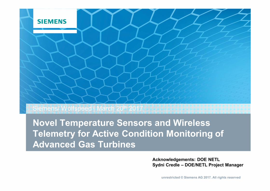
Anatomy of a Smart Component
Smart Component providesreal time information regardingcomponent condition
Thermal spray processenables cost-effectivedeposition of thin filmdevices on complexshaped components
Data acquisition via wirelesstelemetry can be input to algorithmsto predict remaining component life
Page 4 unrestricted © Siemens AG 2017. All rights reserved
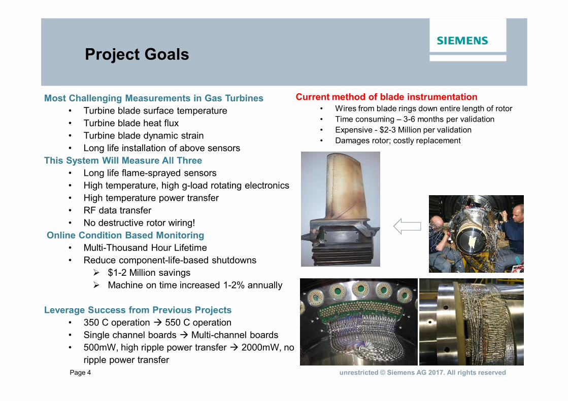
Project Goals
Most Challenging Measurements in Gas Turbines• Turbine blade surface temperature• Turbine blade heat flux• Turbine blade dynamic strain• Long life installation of above sensors
This System Will Measure All Three• Long life flame-sprayed sensors• High temperature, high g-load rotating electronics• High temperature power transfer• RF data transfer• No destructive rotor wiring!
Online Condition Based Monitoring• Multi-Thousand Hour Lifetime• Reduce component-life-based shutdowns
Ø $1-2 Million savingsØ Machine on time increased 1-2% annually
Leverage Success from Previous Projects• 350 C operation à 550 C operation• Single channel boards à Multi-channel boards• 500mW, high ripple power transfer à 2000mW, no
ripple power transfer
Current method of blade instrumentation• Wires from blade rings down entire length of rotor• Time consuming – 3-6 months per validation• Expensive - $2-3 Million per validation• Damages rotor; costly replacement
Page 5 unrestricted © Siemens AG 2017. All rights reserved
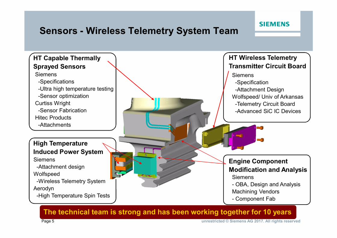
Sensors - Wireless Telemetry System Team
The technical team is strong and has been working together for 10 years
HT Wireless TelemetryTransmitter Circuit Board
High TemperatureInduced Power System
Engine ComponentModification and Analysis
HT Capable ThermallySprayed SensorsSiemens-Specifications-Ultra high temperature testing-Sensor optimization
Curtiss Wright-Sensor Fabrication
Hitec Products-Attachments
Siemens-Attachment design
Wolfspeed-Wireless Telemetry System
Aerodyn-High Temperature Spin Tests
Siemens-Specification-Attachment Design
Wolfspeed/ Univ of Arkansas-Telemetry Circuit Board-Advanced SiC IC Devices
Siemens- OBA, Design and AnalysisMachining Vendors- Component Fab
Page 6 unrestricted © Siemens AG 2017. All rights reserved
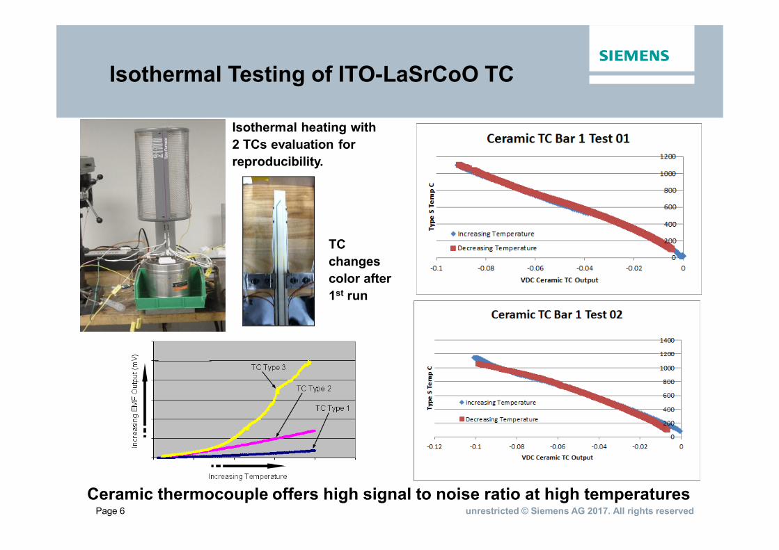
Isothermal Testing of ITO-LaSrCoO TC
Isothermal heating with2 TCs evaluation forreproducibility.
TCchangescolor after1st run
Ceramic thermocouple offers high signal to noise ratio at high temperatures
Page 7 unrestricted © Siemens AG 2017. All rights reserved
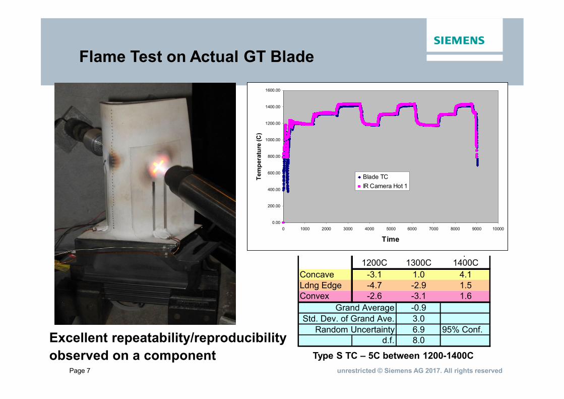
Second to Third Run to Temp.1200C 1300C 1400C
Concave -3.1 1.0 4.1Ldng Edge -4.7 -2.9 1.5Convex -2.6 -3.1 1.6
Grand Average -0.9Std. Dev. of Grand Ave. 3.0
Random Uncertainty 6.9 95% Conf.d.f. 8.0Excellent repeatability/reproducibility
observed on a component
0.00
200.00
400.00
600.00
800.00
1000.00
1200.00
1400.00
1600.00
0 1000 2000 3000 4000 5000 6000 7000 8000 9000 10000
Time
Tem
pera
ture
(C)
Blade TCIR Camera Hot 1
Flame Test on Actual GT Blade
Type S TC – 5C between 1200-1400C

Page 8 unrestricted © Siemens AG 2017. All rights reserved
Design Challenges
Electronics Boards
• Operating temperature 200+ ºC higher than silicon technology can survive
• Thermal expansion and 16,000 G load make electrical connections very difficult
• Vibration and G-load cause cracking of ceramic boards
• Thermal cycling causes metal trace delamination
• Bond wire failures (breaking and g-load flexing)
Rotating Antenna
• Must receive ~1 watt; only 10 cm long; 20mm gap
• Surrounded by grounded metal
• No metal enclosure (magnetic receiver)
• Metal-ceramic interfaces – high vibration and G-load
• Magnetic properties vary greatly over 0-550 ºC range
Stationary Power Inducing Ring
• Magnetic materials infeasible – too much variation in field strength overtemperature
• Thermal expansion and vibration make electrical connections very difficult
• Mounted on grounded metal
• Ceramic/metal interface in high vibration environment
• Need 400 ºC, high frequency cables
Page 9 unrestricted © Siemens AG 2017. All rights reserved
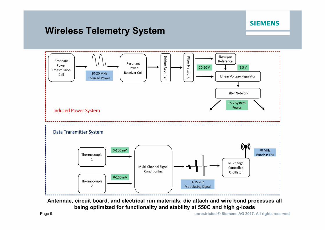
Wireless Telemetry System
Antennae, circuit board, and electrical run materials, die attach and wire bond processes allbeing optimized for functionality and stability at 550C and high g-loads
Page 10 unrestricted © Siemens AG 2017. All rights reserved
10
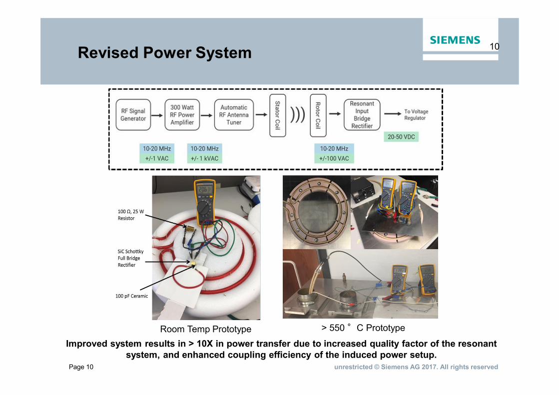
Room Temp Prototype > 550 °C Prototype
Revised Power System
Improved system results in > 10X in power transfer due to increased quality factor of the resonantsystem, and enhanced coupling efficiency of the induced power setup.
Page 11 unrestricted © Siemens AG 2017. All rights reserved
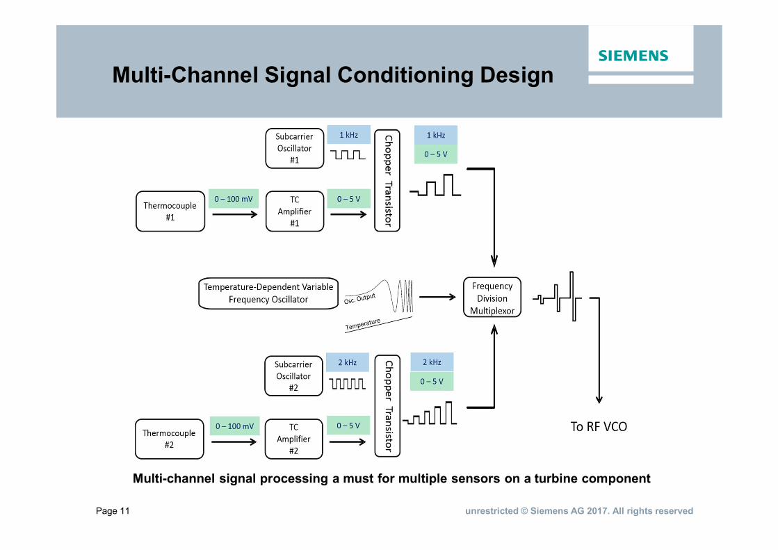
Multi-Channel Signal Conditioning Design
Multi-channel signal processing a must for multiple sensors on a turbine component
Page 12 unrestricted © Siemens AG 2017. All rights reserved
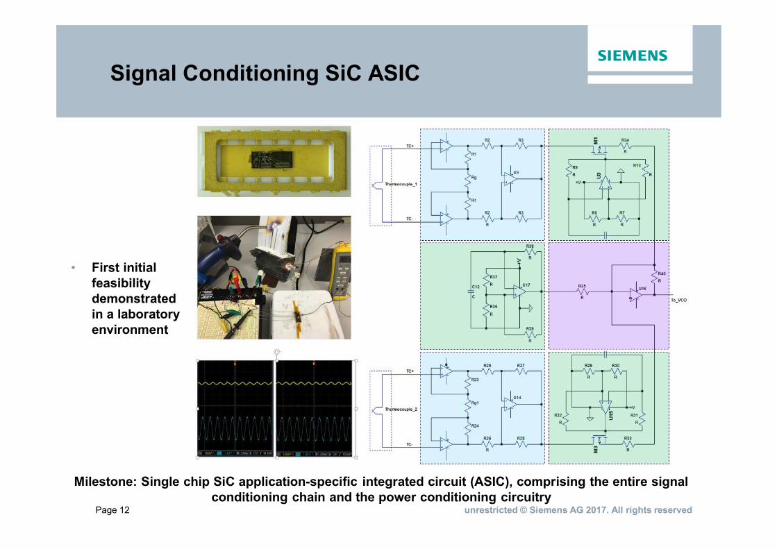
Signal Conditioning SiC ASIC
Milestone: Single chip SiC application-specific integrated circuit (ASIC), comprising the entire signalconditioning chain and the power conditioning circuitry
• First initialfeasibilitydemonstratedin a laboratoryenvironment
Page 13 unrestricted © Siemens AG 2017. All rights reserved
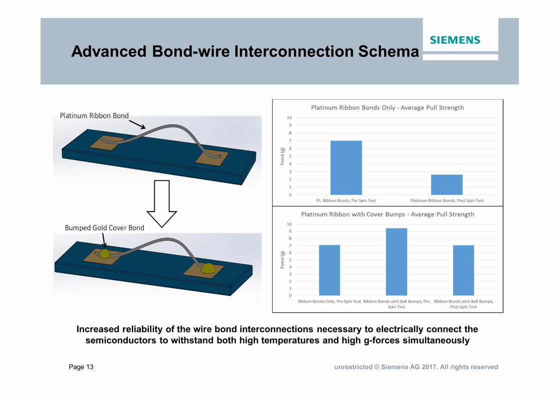
Advanced Bond-wire Interconnection Schema
Increased reliability of the wire bond interconnections necessary to electrically connect thesemiconductors to withstand both high temperatures and high g-forces simultaneously
Page 14 unrestricted © Siemens AG 2017. All rights reserved
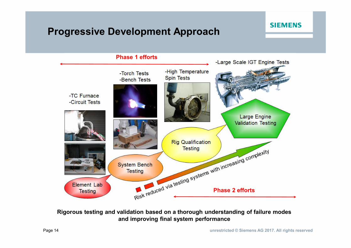
Progressive Development Approach
Rigorous testing and validation based on a thorough understanding of failure modesand improving final system performance
Phase 1 efforts
Phase 2 efforts
Page 15 unrestricted © Siemens AG 2017. All rights reserved
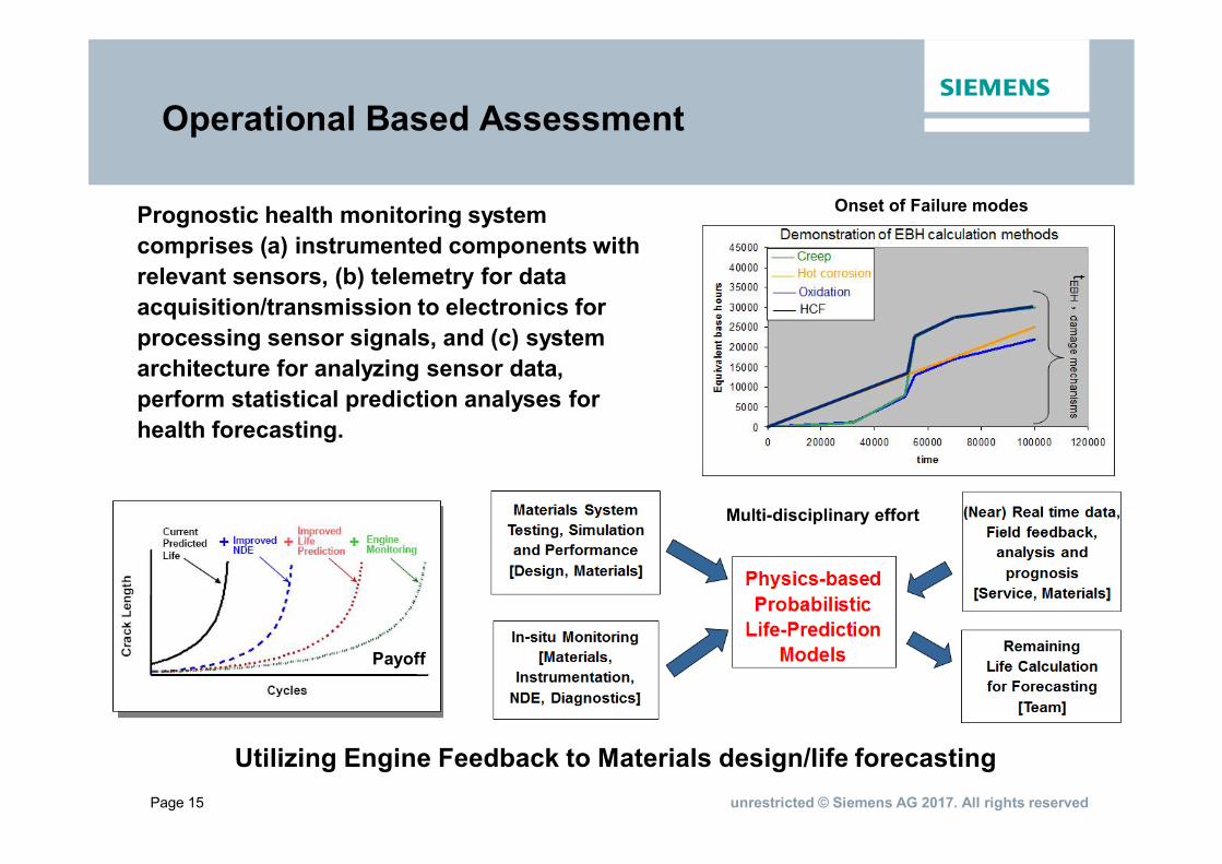
Prognostic health monitoring systemcomprises (a) instrumented components withrelevant sensors, (b) telemetry for dataacquisition/transmission to electronics forprocessing sensor signals, and (c) systemarchitecture for analyzing sensor data,perform statistical prediction analyses forhealth forecasting.
Utilizing Engine Feedback to Materials design/life forecasting
Payoff
Multi-disciplinary effort
Onset of Failure modes
Operational Based Assessment
Page 16 unrestricted © Siemens AG 2017. All rights reserved
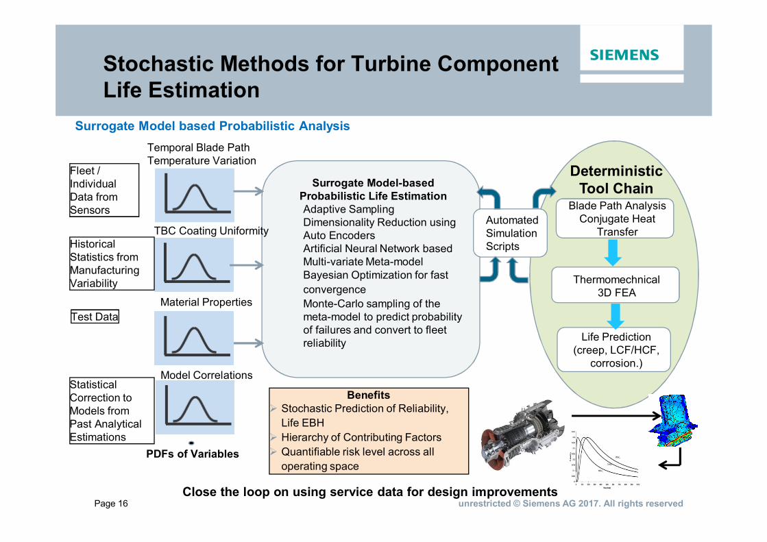
Stochastic Methods for Turbine ComponentLife Estimation
Surrogate Model based Probabilistic Analysis
Surrogate Model-basedProbabilistic Life EstimationAdaptive SamplingDimensionality Reduction usingAuto EncodersArtificial Neural Network basedMulti-variate Meta-modelBayesian Optimization for fastconvergenceMonte-Carlo sampling of themeta-model to predict probabilityof failures and convert to fleetreliability
Temporal Blade PathTemperature Variation
TBC Coating Uniformity
Fleet /IndividualData fromSensors
HistoricalStatistics fromManufacturingVariability
StatisticalCorrection toModels fromPast AnalyticalEstimations
Model Correlations
AutomatedSimulationScripts
Material PropertiesTest Data
PDFs of Variables
Blade Path AnalysisConjugate Heat
Transfer
Life Prediction(creep, LCF/HCF,
corrosion.)
DeterministicTool Chain
BenefitsØ Stochastic Prediction of Reliability,
Life EBHØ Hierarchy of Contributing FactorsØ Quantifiable risk level across all
operating space
Thermomechnical3D FEA
Close the loop on using service data for design improvements
Page 17 unrestricted © Siemens AG 2017. All rights reserved
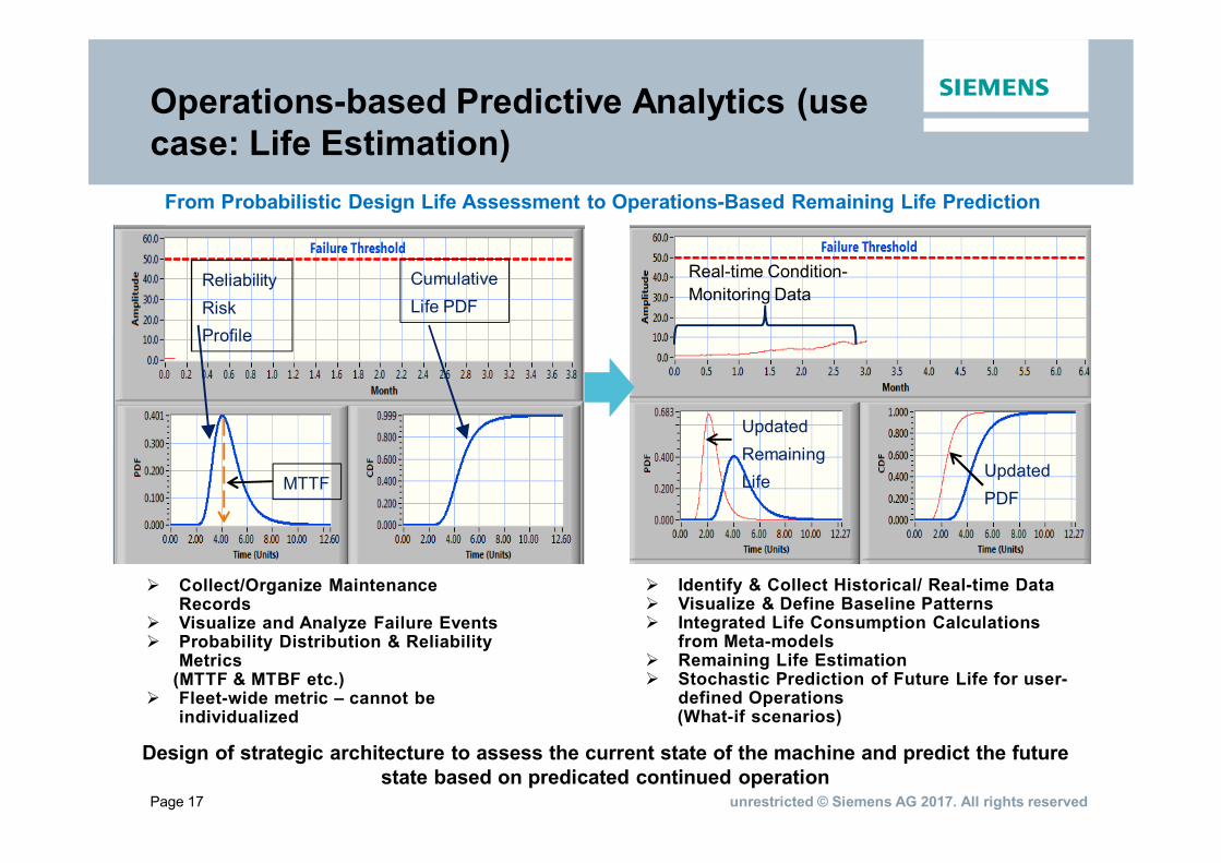
Operations-based Predictive Analytics (usecase: Life Estimation)
ReliabilityRiskProfile
MTTF
CumulativeLife PDF
Real-time Condition-Monitoring Data
UpdatedPDF
UpdatedRemainingLife
From Probabilistic Design Life Assessment to Operations-Based Remaining Life Prediction
Ø Collect/Organize MaintenanceRecords
Ø Visualize and Analyze Failure EventsØ Probability Distribution & Reliability
Metrics(MTTF & MTBF etc.)
Ø Fleet-wide metric – cannot beindividualized
Ø Identify & Collect Historical/ Real-time DataØ Visualize & Define Baseline PatternsØ Integrated Life Consumption Calculations
from Meta-modelsØ Remaining Life EstimationØ Stochastic Prediction of Future Life for user-
defined Operations(What-if scenarios)
Design of strategic architecture to assess the current state of the machine and predict the futurestate based on predicated continued operation
Page 18 unrestricted © Siemens AG 2017. All rights reserved
Summary
§ Siemens and its partners are developing Smart Component systems toprovide real-time information for stationary and rotating components toenable a transition to condition-based maintenance.§ Phase 1 achievements include: a) Demonstration of ceramicthermocouples that showed > 4x improvement in voltage (emf) outputcompared to metallic thermocouples (100 mV to 25 mV at 1200C), b)Demonstration of a cutting edge single chip silicon carbide (SiC) integratedcircuits (IC) operational amplifier based system to perform analog signaland power conditioning of the sensor signal c) Development of a newinduced power driver and receiver geometry capable of transferring 5W ofpower over 17 mm, which constitutes an order magnitude increase inpower as compared to 0.5-1 W obtained from original designs, d) Improvedwire-bond design capable of withstanding high centrifugal loading, and e)Successful lab test of integrated sensor-wireless telemetry package on agas turbine blade§ Phase 2 program will focus on validation testing of sensor-wirelesstelemetry package in gas turbine engine and advanced operation-basedassessment (OBA) model utilizing artificial intelligence