
Novel Technologies in Radiotherapy: Protons and Magnetic … · · 2012-04-30Novel Technologies...
66
Novel Technologies in Radiotherapy: Protons and Magnetic Resonance Imaging Magnetic Resonance Imaging Todd Pawlicki UC San Diego UC San Diego
Transcript of Novel Technologies in Radiotherapy: Protons and Magnetic … · · 2012-04-30Novel Technologies...

Novel Technologies in Radiotherapy: Protons and
Magnetic Resonance ImagingMagnetic Resonance Imaging
Todd Pawlicki
UC San DiegoUC San Diego

DisclosureDisclosure
• I have no conflicts of interest to discloseI have no conflicts of interest to disclose.

Learning ObjectivesLearning Objectives
• Understand the physics of protons beamsUnderstand the physics of protons beams
• Describe differences between proton & photon plans
• Summarize basic physics of MRI
• Discuss applications of MRI in radiotherapy• Discuss applications of MRI in radiotherapy

Question #1Question #1
• What are two methods to create a clinicalWhat are two methods to create a clinical proton beam?
a) Passive scattering and active scanninga) Passive scattering and active scanning
b) Blocks, bolus and wedges
c) Active scattering and passive scanningc) Active scattering and passive scanning
d) None of the above

Question #2Question #2
• What property of tissues makes nuclearWhat property of tissues makes nuclear magnetic resonance useful for imaging?
a) Angular momentum is independent of RF energya) Angular momentum is independent of RF energy
b) Tissues have characteristic relaxation times
c) RF attenuation is linearly related to tissue densityc) RF attenuation is linearly related to tissue density
d) None of the above

Proton TherapyProton Therapy
• Physics of protonsPhysics of protons– Dose deposition
– Creating a proton beam
• Proton beam planningp g

Some Proton HistorySome Proton History• Cyclotron invented in 1930
– Lawrence EO Livingston MS The production of high speed protons without the use of– Lawrence EO, Livingston MS. The production of high speed protons without the use of high voltages. Physical Review 1931.
• Suggested for medical use in 1946Wil RR R di l i l f f t t R di l 1946– Wilson RR. Radiological use of fast protons. Radiology 1946.
• First patients treated in 1958– Tobias CA et al. Pituitary irradiation with high-energy proton beams a preliminary report.
Cancer Research 1958.
– In 1961, the Harvard Cyclotron Laboratory started treating intracranial lesions
• First hospital-based system developed at the LLUMCp y p– First patient treated in 1991
– Slater JM et al. The proton treatment center at Loma Linda University Medical Center: rational for and description of its development. IJROBP 1991.

Physical PropertiesPhysical Properties
Particle Symbol Charge Rest Mass
Electron −1 0.511 MeV,e β− −
Positron +1 0.511 MeV
Proton +1 1836 ⋅ 0.511 MeV
,e β+ +
11,p H+ +
Neutron 0 1839 ⋅ 0.511 MeV10,n n
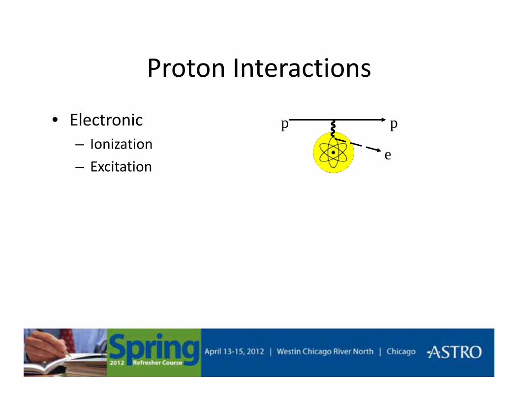
Proton InteractionsProton Interactions
• Electronic ppElectronic– Ionization
– Excitatione
pp

Proton InteractionsProton Interactions
• Nuclear(i) p`
p θNuclearI. Multiple Coulomb scattering
Small θII El ti l lli i
p
II. Elastic nuclear collisionLarge θ
III. Inelastic nuclear interaction p
p`
nucleus
(ii)
nucleus
p`e
γ, npnucleus
(iii)

Ionization DensityIonization Density
0 5 MeV Proton
10 MeV Proton
0.5 MeV Proton
1 MeV Electron
5 keV Electron
Hall. Radiology for the Radiologist. 4th ed. 1994.
5 keV Electron

Linear Energy Transfer (LET)Linear Energy Transfer (LET)
• Energy transferred per unit track lengthEnergy transferred per unit track length
LET dEdl
=
• Useful as a simple way to indicate radiation quality
dl
p y q yand biological effectiveness

Radiation LET (keV/μm)
Cobalt-60 γ-rays 0.2
250 keV x-rays 2.5
10 MeV protons 4.7
150 MeV protons 0.5
Hall. Radiology for the Radiologist. 4th ed. 1994.

LET versus DepthLET versus Depth
40 MeV 100 MeV 250 MeV40 MeV 100 MeV 250 MeV
Depth (cm)

Relative Biological EffectivenessRelative Biological Effectiveness
• Equal doses of difference types of radiation do notEqual doses of difference types of radiation do not produce equal biological effects
RBE x rayD −
• RBE depends on
RBE y
testD=
• RBE depends on – Dose
– Biological system (cell type) Hall. Radiology for the Radiologist. 4th ed. 1994.
– Clinical endpoint (early or late effects)

RBE for ProtonsRBE for Protons
• RBE is a function of LETRBE is a function of LET– RBE is not constant with depth
– Must be careful at the distal end of the target and/or near critical structurescritical structures
• Clinical RBE for protons ≅ 1.1– 1 Gy proton dose ≅ 1.1 Gy Cobalt dose – A single value might not be sufficient
Carabe A Moteabbed M Depauw N Schuemann J Paganetti HCarabe A, Moteabbed M, Depauw N, Schuemann J, Paganetti H. Range uncertainty in proton therapy due to variable biological effectiveness. Phys Med Biol. 2012;57(5):1159-72.
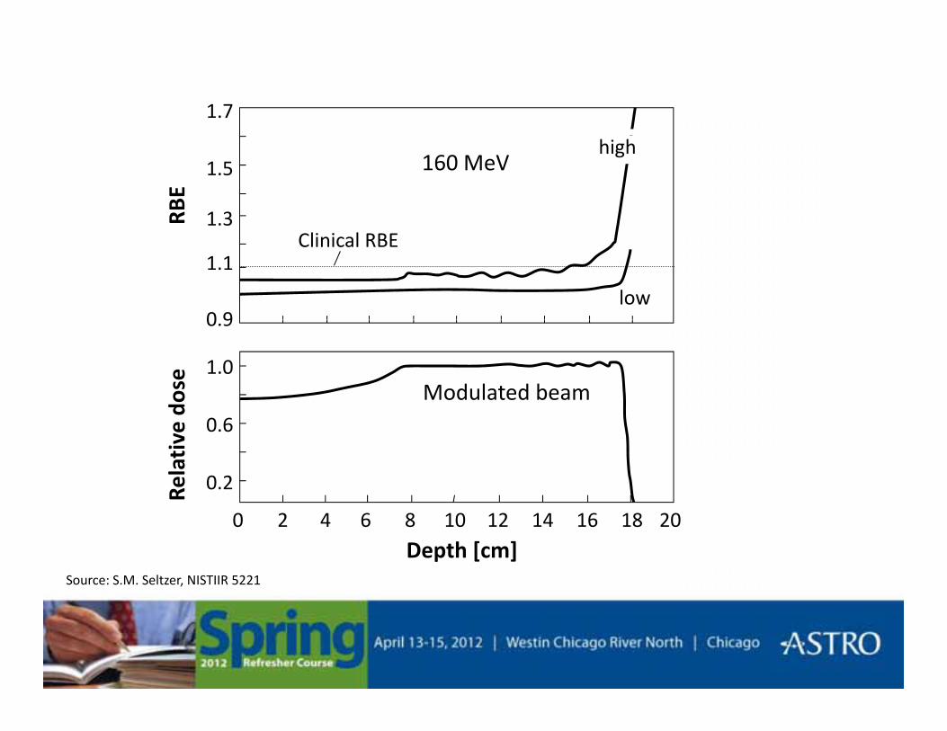
1.7
1.3
1.5 160 MeVRB
Ehigh
0 9
1.1
low
Clinical RBE
0.9
1.0Modulated beam
dose
0.6
0.2Rela
tive
d
4 6 8 12 14 16 18 200 102
Depth [cm]Source: S.M. Seltzer, NISTIIR 5221

Depth DoseDepth Dose
PhotonsBragg Peak
SOBP
Photons
Electrons Protons
http://commons.wikimedia.org/wiki/Category:Radiation_therapy
Schulz-Ertner et al. Semin Radiat Oncol, 2006.

Cobalt-60
20 MV X-rays
160 MeV Protons
Koehler and Preston. Radiology(104)191-195, 1972.

Proton Beam RequirementsProton Beam Requirements
• Maximum energy should be about 250 MeVMaximum energy should be about 250 MeV
• Energy should be variable starting at ∼70 MeV
• The accelerator should be as small as possible with minimum weight

CyclotronCyclotronMagnet
“Dees”
RF
Magnetic Field
Proton Source
Proton Beam ( )magF q v B= ⋅ ×r rr
eleF q E= ⋅r r

Proton BeamsProton Beams
• Currently, two proton accelerator options basedCurrently, two proton accelerator options based on the cyclotron
Cyclotron– Cyclotron• Protons revolve at the same frequency regardless of energy
or orbit radius
– Synchrotron• The magnetic field strength and RF frequency are increased
in synchrony with the increase in beam energyin synchrony with the increase in beam energy
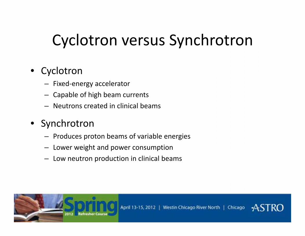
Cyclotron versus SynchrotronCyclotron versus Synchrotron
• CyclotronCyclotron– Fixed-energy accelerator
– Capable of high beam currents
d l l b– Neutrons created in clinical beams
• Synchrotron– Produces proton beams of variable energies
– Lower weight and power consumption
– Low neutron production in clinical beams

Clinically Useful Proton BeamsClinically Useful Proton Beams
• There are two main approachesThere are two main approaches
• Passive scattering systemsFixed depth of penetration– Fixed depth of penetration
– Fixed modulation
• Active scanning systems• Active scanning systems– Irradiation the target using a narrow beam
– Beam controlled in three dimensions
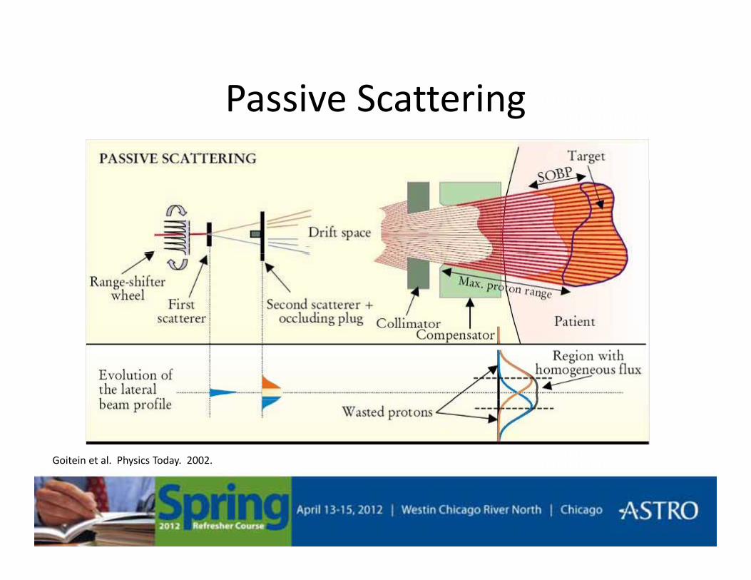
Passive ScatteringPassive Scattering
Goitein et al. Physics Today. 2002.
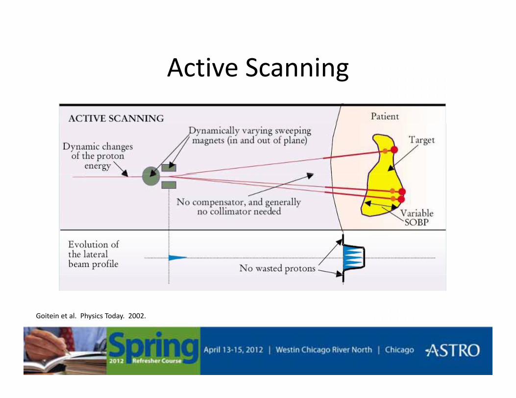
Active ScanningActive Scanning
Goitein et al. Physics Today. 2002.

Active (Raster) ScanningActive (Raster) Scanning
Schulz-Ertner et al. Semin Radiat Oncol, 2006.
Treatment PlanningTreatment Planning
• Acquisition of imaging data (CT, MRI)Acquisition of imaging data (CT, MRI)
• Conversion of CT values into stopping power
• Delineation of regions of interest
• Selection of proton beam directions• Selection of proton beam directions

Treatment PlanningTreatment Planning
• Design of each beamDesign of each beam
• Optimization of the plan Including variable energy with each beam– Including variable energy with each beam
• Dose calculation models– Broad beam (measurement)
– Pencil beam
– Monte Carlo

Dose DistributionsDose Distributions
Photons
Protons
MacDonald et al. Cancer Investigation. 2006.

Dose DistributionsDose Distributions
Greco & Wolden. Cancer. 2007.

Dose DistributionsDose Distributions
Suit et al. Acta Oncologica. 2003.

Kase et al. A Treatment Planning Comparison of Passive-Scattering and Intensity-ModulatedProton Therapy for Typical Tumor Sites. J Radiat Res, 2011.

PET Treatment VerificationPET Treatment Verification
Remmele et al. A deconvolution approach for PET-based dose reconstruction in proton radiotherapy. PMB 2011.

Challenges in Proton TherapyChallenges in Proton Therapy
• Patient related• Patient related– Patient setup/movements, Organ motion, Body contour, Target definition
• Biolog related• Biology related– Relative biological effectiveness (RBE)
Ph i l t d• Physics related– CT number conversion, Dose calculation
M hi l t d• Machine related– Device tolerances, Beam energy

Final CommentsFinal Comments

Magnetic Resonance ImagingMagnetic Resonance Imaging
• Physics of magnetic resonance imagingPhysics of magnetic resonance imaging– Nuclear magnetic resonance
– Image creation
• Uses of MRI in radiotherapy– In-room systems and functional imaging

A Bit of MRI HistoryA Bit of MRI History• Found a method to tune in on magnetic fields of
spinning nuclei in 1946spinning nuclei in 1946– Purcell E.M., Torrey H.C., Pound R.V., Resonance Absorption by Nuclear Magnetic
Moments in a Solid, Phys Rev 69, 37-38 (1946). [Harvard]
– Bloch F Hansen WW Packard M E Nuclear induction Phys Rev 69 127 (1946)Bloch F., Hansen W.W., Packard M.E., Nuclear induction, Phys Rev 69, 127 (1946) [Stanford]
• First MR image formed in 19731973 h t bli h d i N t titl d "I f ti b i d d l l– 1973 a short paper was published in Nature entitled "Image formation by induced local interaction; examples employing magnetic resonance". The author was Paul Lauterbur, a Professor of Chemistry at the State University of New York at Stony Brook.
• The first commercial MR scanner installed in 1983• The first commercial MR scanner installed in 1983– The Department of Diagnostic Radiology at the University of Manchester Medical School
in Europe (from Picker Ltd.)
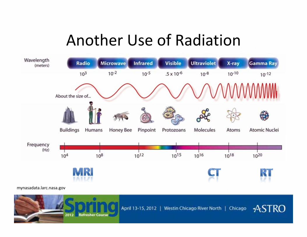
Another Use of RadiationAnother Use of Radiation
mynasadata.larc.nasa.gov

Constituents of MatterConstituents of Matter
• Atoms → Nucleus + Electrons → ProtonsAtoms → Nucleus + Electrons → Protons
• Charged particle’s spin– Angular momentum suggested by Pauli in 1924
– A spinning charge creates a magnetic field, Br
BrB
Br
Br
No external magnetic field
B
Bushburg et al. The Essential Physics of Medical Imaging. 2nd Ed, 2002. Fig 14-2 .

Apply External Magnetic FieldApply External Magnetic Field
• Charged particles precessCharged particles precess about the magnetic field
• Net magnetic momentg
External magnetic field ( ) applied0Br
Bushburg et al. The Essential Physics of Medical Imaging. 2nd Ed, 2002. Fig 14-3.

Magnetic PropertiesMagnetic Properties
• Processional frequency depends on field strengthProcessional frequency depends on field strength and type of nucleus,– is the gyromagnetic ratio
0 0Bω γ=γ
Nuclei γ/2π (MHz/T)11H 42.58
23Na 11.313C 10.7

Pykett. NMR Imaging in Medicine. Sci Am, 1982.

Bushburg et al. The Essential Physics of Medical Imaging. 2nd Ed, 2002.

Pykett. NMR Imaging in Medicine. Sci Am, 1982.
RF PulseαM
a
α
α
u se
Mb
e
TIME
αM
M M
cd
TIMETIME
T2 DephasingT1 Relaxation
α
α
/ 2( ) t TxM t e− ( )/ 1
0( ) ( ) 1 t TzM t M t e−⋅ −
M MTIME
T1 Relaxation

T1 and T2T1 and T2
• T1, longitudinal relaxation timeT1, longitudinal relaxation time– Restoration of the precession of the nuclei in the static B field
• T2, transverse relaxation time– Following the RF excitation, the free induction signal vanishes because
the transverse component of the magnetization decaysthe transverse component of the magnetization decays
• T1 and T2 are tissue specific– Distinguishing characteristic of tissues that makes nuclear magnetic
resonance useful for imaging
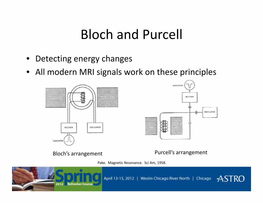
Bloch and PurcellBloch and Purcell
• Detecting energy changes
• All modern MRI signals work on these principles
Purcell’s arrangementBloch’s arrangementPake. Magnetic Resonance. Sci Am, 1958.
Magnetic FieldsMagnetic Fields
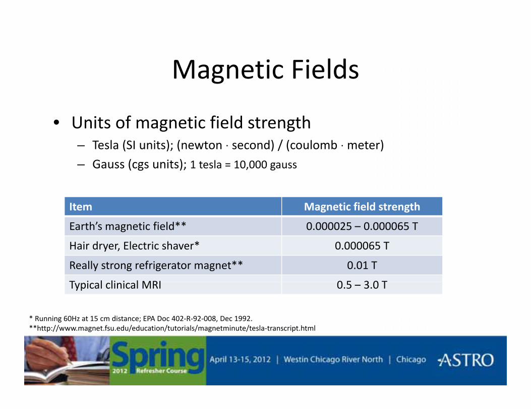
• Units of magnetic field strengthUnits of magnetic field strength– Tesla (SI units); (newton ⋅ second) / (coulomb ⋅ meter)– Gauss (cgs units); 1 tesla = 10,000 gauss
Item Magnetic field strength
Earth’s magnetic field** 0.000025 – 0.000065 Tg
Hair dryer, Electric shaver* 0.000065 T
Really strong refrigerator magnet** 0.01 T
T i l li i l MRI 0 5 3 0 TTypical clinical MRI 0.5 – 3.0 T
* Running 60Hz at 15 cm distance; EPA Doc 402-R-92-008, Dec 1992.**http://www.magnet.fsu.edu/education/tutorials/magnetminute/tesla-transcript.html

Pulse SequencesPulse Sequences• Spin Echo
• Inversion recovery– First tip by 180o, then let decay (longitudinally) for TI (∼300ms)
Then add on a standard spin echo (90o + 180o)– Then add on a standard spin echo (90o + 180o)
– Can repeat for several TI’s.
– Images are heavily T1-weighted RFEcho
Slide Courtesy Shantanu Sinha, PhD, UC San DiegoInversion Time
(TI)
90o
180o
TE/2
180o
TE/2( )

Typical T1 and T2 ValuesTypical T1 and T2 ValuesTissue T1 for 0.5 T
(msec)T1 for 1.5 T
(msec)T2
(msec)
Fat 210 260 80
Muscle 550 870 45
White matter 500 780 90White matter 500 780 90
Gray matter 650 900 100
CSF 1800 2400 160

T1 Weighted
Bushburg et al. The Essential Physics of Medical Imaging. 2nd Ed, 2002. Fig 14-21.
T1 Weighted
ImageImage Contrast

T2 Weighted
Bushburg et al. The Essential Physics of Medical Imaging. 2nd Ed, 2002. Fig 14-23.
T2 Weighted
ImageImage Contrast

Proton Density Weighted
Bushburg et al. The Essential Physics of Medical Imaging. 2nd Ed, 2002. Fig 14-22.
Proton Density Weighted
ImageImage Contrast

FLAIR
Bushburg et al. The Essential Physics of Medical Imaging. 2nd Ed, 2002. Fig 14-25, 14-26, and 14-27.
FLAIR
RFEcho
90o
RF
180o180o
Inversion Time(TI)
TE/2 TE/2

NMR: A Perspective on Imaging. General Electric Company, 1982. Fig 14.Brown. NMR Imaging: Principles and Recent Progress. SCA Conference Paper Number 8812, 1988. Fig 21.
Single frequency
An image of NxN pixels requires N independent projections, each defined by N points.
Two frequencies
Time Domain
Frequency Domain
MR image reconstruction by back projection of the MR frequency domain signal is equivalent to using the CTsignal is equivalent to using the CT attenuation profiles to create a CT image.

No B-field gradient
B-field gradient
Both vials resonate at:
Vials resonate at:
Bω γ ( ) Bδ⎛ ⎞⎜ ⎟
r
Brown. NMR Imaging: Principles and Recent Progress. SCA Conference Paper Number 8812, 1988. Fig 24.
0 0Bω γ= ( ) 0x xx
ω ω γδ
= ⎜ ⎟⎝ ⎠

Image Construction
Smith and Ranallo. A non-mathematical approach to basic MRI. 1989. Fig 18-1.
Image Construction
• To make a “slice” (i.e., constrain z), make the RFTo make a slice (i.e., constrain z), make the RF excitation itself spatially-selective
0ω ω>
0ω ω=
0B B>
0B B= 0
0ω ω<
0
0B B<
0 0Bω γ=
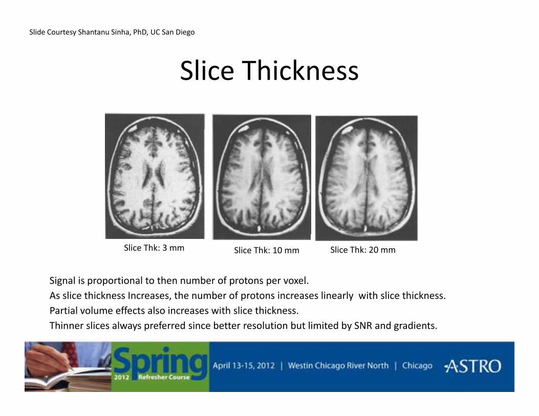
Slice Thickness
Slide Courtesy Shantanu Sinha, PhD, UC San Diego
Slice Thickness
Slice Thk: 3 mm Slice Thk: 10 mm Slice Thk: 20 mm
•Signal is proportional to then number of protons per voxel.•As slice thickness Increases, the number of protons increases linearly with slice thickness.•Partial volume effects also increases with slice thickness.•Thinner slices always preferred since better resolution but limited by SNR and gradients.

Enhanced ContrastEnhanced Contrast
Gadolinium T1 contrast enhancement by IV injection of exogenousGadolinium T1 contrast enhancement by IV injection of exogenous contrast agent.
lesion
Slide Courtesy Shantanu Sinha, PhD, UC San Diego

Contrast From FlowContrast From Flow
MR Angiography utilizes inherent differences in contrast between g g p yflowing (blood) spins and stationary tissue.
Time-of-Flight MRA for visualization of vasculature.
Slide Courtesy Shantanu Sinha, PhD, UC San Diego

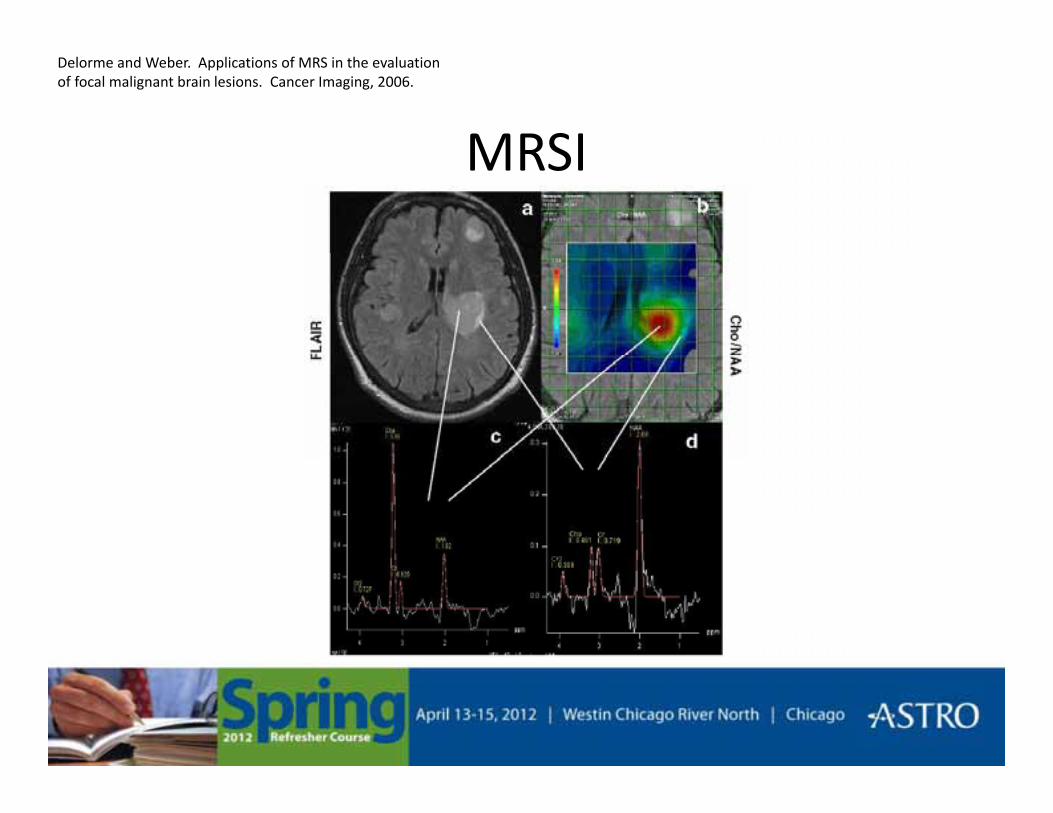
MRSI• MR spectroscopy and MR imaging methods
MRSI
– Produce a spectrum identifying different chemical compounds (metabolites) in various tissues
M t b lit ti diff ti t b t ti• Metabolite ratios differentiate between active tumor, normal tissue, and necrosis
Hunjan et al. IJROBP, 2003.
MRSI
Delorme and Weber. Applications of MRS in the evaluation of focal malignant brain lesions. Cancer Imaging, 2006.
MRSI

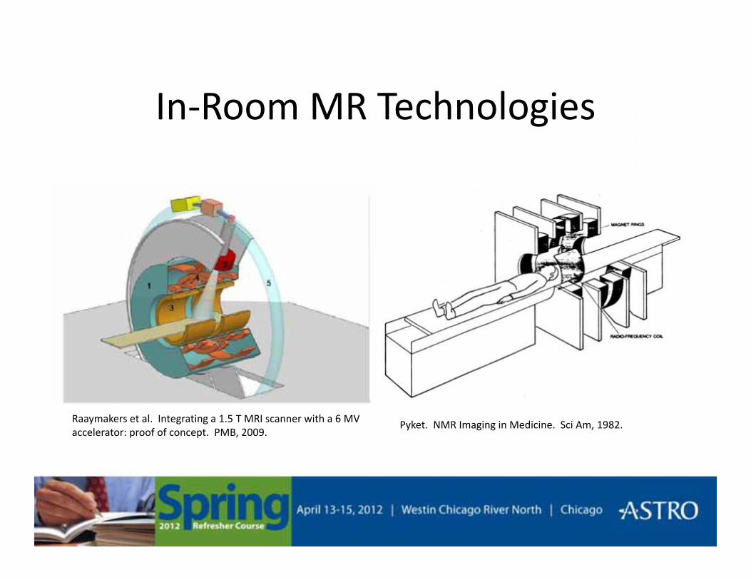
In Room MR TechnologiesIn-Room MR Technologies
Oborn et al. Med Phys, 2010.Courtesy of Viewray, Inc.
In Room MR TechnologiesIn-Room MR Technologies
Raaymakers et al. Integrating a 1.5 T MRI scanner with a 6 MV accelerator: proof of concept. PMB, 2009.
Pyket. NMR Imaging in Medicine. Sci Am, 1982.

Question #1Question #1
• What are two methods to create a clinicalWhat are two methods to create a clinical proton beam?
a) Passive scattering and active scanninga) Passive scattering and active scanning
b) Blocks, bolus and wedges
c) Active scattering and passive scanningc) Active scattering and passive scanning
d) None of the above

Question #2Question #2
• What property of tissues makes nuclearWhat property of tissues makes nuclear magnetic resonance useful for imaging?
a) Angular momentum is independent of RF energya) Angular momentum is independent of RF energy
b) Tissues have characteristic relaxation times
c) RF attenuation is linearly related to tissue densityc) RF attenuation is linearly related to tissue density
d) None of the above