Novel Mechanical Occlusion Device for Transcervical Sterilization
6
Abstract—Various contemporary technologies have improved the strategies for permanent female sterilization. At present, the transcervical approach is being used as a sterilization technique, which obviates the need for either general anesthesia or surgical incision. However, current methods of transcervical sterilization are unable to provide instant occlusion. This paper presents the design, development and verification of a novel mechanical occlusion device which achieve both instant and permanent female sterilization via a transcervical approach. The device is designed to provide an instant mechanical occlusion by deploying, under hysteroscopic visualization an implant into the intramural segment of the fallopian tube. The design of the device has been accomplished through Computer Aided Design (CAD), Finite Element Method (FEM) and experimental testing. Validation has been performed following a number of successful bench-top deployments in-air and in-vitro on animal tissue and explanted human uteri. During hydraulic pressure testing of the explanted uteri using saline solution and methylene blue, it was observed that the device provided an instant occlusion of the fallopian tubes. Initial results suggest that the device provides a safe, effective and instant method of permanent female sterilization. Further development work is ongoing in preparation for “first-in-man” clinical trials. Index Terms—Instant Mechanical Occlusion, Hysteroscope, Transcervical sterilization. I. INTRODUCTION Surgical occlusion of the fallopian tubes is a widely used method of female sterilization because of its proven safety and effectiveness. The traditional surgical procedures are minilaparotomy and tubal ligation [1]. The advancements in these procedures have led to approaches such as electrocoagulation or clip or ring application to the tubes. However, such approaches to female sterilization are relatively high risk due to the requirement of general anesthesia with vascular damage, injury to the bowel, bladder, or uterus being potential complications. In addition, these procedures may be associated with postoperative pain [2]. The transcervical approach is an alternative to incisional procedures for interval tubal sterilization as it eliminates the requirement for general anesthesia and surgery. The most common methods of transcervical sterilization procedures depend on either destructive or mechanically occlusive approaches. Destructive methods have included chemical Manuscript received January 13, 2010. This work is financially supported by Enterprise Ireland. Rehan M. is with Dublin City University, Glasnevin, D9, Dublin, Ireland (phone: +353 851384034, email: [email protected]) Coleman J. E. is with Alta Science, Citywest Campus, Citywest, D24, Dublin, Ireland (email: [email protected]) Olabi A. G. is with Dublin City University, Glasnevin, D9, Dublin, Ireland (email: [email protected]) caustics, tissue adhesives, thermic induction and lasers [3], [4]. Destructive occlusion results in both a low success rate and morbidity [2], [3]. Contrary to the destructive methods of burning, freezing or fibrosing, the tubal ostia can be occluded by hysteroscopically applied mechanical devices. Such mechanical occlusion can be achieved either by placing a pre-formed plug or device in the uterotubal orifice or by formed-in-situ methods. The technological developments in endoscopes, light transmission devices, optical resolution, catheters and tubal cannulation evolved some new technologies such as the Adiana and Essure devices [3]. However, both the Adiana [5], [6] and Essure [7 to 9] procedures rely on tissue in-growth from the surrounding tubal walls and effectual 3 months after device placement. This can be inconvenient for the patient, who has to use an alternate contraception during this time, which means an additional cost of contraception and a procedure to confirm tubal occlusion. Therefore, the requirement was to develop a transcervical approach that can provide an instant occlusion of the fallopian tube. This paper presents the design, development and verification of a novel mechanical occlusion device which achieves permanent female sterilization via the transcervical approach. Using a standard hysteroscope of 5- French (F) operating channel, the device deploy an implant [10] into the intramural section of the fallopian tube to provide an instant mechanical occlusion. The device comprises an implant, a guiding system and an actuator handle. The implant is made of biocompatible grade stainless steel (SS) 316LVM and includes a guide tip at the distal end and a novel design of laser cut slots on the cylindrical body. These slots transform into two sets of wings that penetrate into the ostium and uterine muscle tissue entrapping the tissue and thereby plugging the entrance of the fallopian tube. The ergonomically designed actuator controls the deployment and release of the implant at the target location by applying required forces in a specified sequence. The design of the device was achieved through FEA, prototyping and experimentations. FEA simulations were performed to simulate the mechanical behavior of the device during deployments and handling. The device was validated a number of times by successful deployments on the bench, in animal tissue and in explanted human uteri. During deployments in the latter, it was observed that the device provided both an instant and effective occlusion of the fallopian tube. II. MATERIALS AND METHODS The device is designed, under hysteroscopic visualization to deploy an implant into the intramural segment of the Novel Mechanical Occlusion Device for Transcervical Sterilization Rehan M, Coleman J. E., Olabi A. G. Proceedings of the World Congress on Engineering 2010 Vol I WCE 2010, June 30 - July 2, 2010, London, U.K. ISBN: 978-988-17012-9-9 ISSN: 2078-0958 (Print); ISSN: 2078-0966 (Online) WCE 2010
Transcript of Novel Mechanical Occlusion Device for Transcervical Sterilization

Abstract—Various contemporary technologies have
improved the strategies for permanent female sterilization. At
present, the transcervical approach is being used as a
sterilization technique, which obviates the need for either
general anesthesia or surgical incision. However, current
methods of transcervical sterilization are unable to provide
instant occlusion. This paper presents the design, development
and verification of a novel mechanical occlusion device which
achieve both instant and permanent female sterilization via a
transcervical approach. The device is designed to provide an
instant mechanical occlusion by deploying, under
hysteroscopic visualization an implant into the intramural
segment of the fallopian tube. The design of the device has
been accomplished through Computer Aided Design (CAD),
Finite Element Method (FEM) and experimental testing.
Validation has been performed following a number of
successful bench-top deployments in-air and in-vitro on animal
tissue and explanted human uteri. During hydraulic pressure
testing of the explanted uteri using saline solution and
methylene blue, it was observed that the device provided an
instant occlusion of the fallopian tubes. Initial results suggest
that the device provides a safe, effective and instant method of
permanent female sterilization. Further development work is
ongoing in preparation for “first-in-man” clinical trials.
Index Terms—Instant Mechanical Occlusion, Hysteroscope,
Transcervical sterilization.
I. INTRODUCTION
Surgical occlusion of the fallopian tubes is a widely used
method of female sterilization because of its proven safety
and effectiveness. The traditional surgical procedures are
minilaparotomy and tubal ligation [1]. The advancements in
these procedures have led to approaches such as
electrocoagulation or clip or ring application to the tubes.
However, such approaches to female sterilization are
relatively high risk due to the requirement of general
anesthesia with vascular damage, injury to the bowel,
bladder, or uterus being potential complications. In
addition, these procedures may be associated with
postoperative pain [2].
The transcervical approach is an alternative to incisional
procedures for interval tubal sterilization as it eliminates the
requirement for general anesthesia and surgery. The most
common methods of transcervical sterilization procedures
depend on either destructive or mechanically occlusive
approaches. Destructive methods have included chemical
Manuscript received January 13, 2010. This work is financially
supported by Enterprise Ireland. Rehan M. is with Dublin City University, Glasnevin, D9, Dublin,
Ireland (phone: +353 851384034, email: [email protected])
Coleman J. E. is with Alta Science, Citywest Campus, Citywest, D24, Dublin, Ireland (email: [email protected])
Olabi A. G. is with Dublin City University, Glasnevin, D9, Dublin,
Ireland (email: [email protected])
caustics, tissue adhesives, thermic induction and lasers [3],
[4]. Destructive occlusion results in both a low success rate
and morbidity [2], [3].
Contrary to the destructive methods of burning, freezing
or fibrosing, the tubal ostia can be occluded by
hysteroscopically applied mechanical devices. Such
mechanical occlusion can be achieved either by placing a
pre-formed plug or device in the uterotubal orifice or by
formed-in-situ methods. The technological developments in
endoscopes, light transmission devices, optical resolution,
catheters and tubal cannulation evolved some new
technologies such as the Adiana and Essure devices [3].
However, both the Adiana [5], [6] and Essure [7 to 9]
procedures rely on tissue in-growth from the surrounding
tubal walls and effectual 3 months after device placement.
This can be inconvenient for the patient, who has to use an
alternate contraception during this time, which means an
additional cost of contraception and a procedure to confirm
tubal occlusion. Therefore, the requirement was to develop
a transcervical approach that can provide an instant
occlusion of the fallopian tube.
This paper presents the design, development and
verification of a novel mechanical occlusion device which
achieves permanent female sterilization via the
transcervical approach. Using a standard hysteroscope of 5-
French (F) operating channel, the device deploy an implant
[10] into the intramural section of the fallopian tube to
provide an instant mechanical occlusion. The device
comprises an implant, a guiding system and an actuator
handle. The implant is made of biocompatible grade
stainless steel (SS) 316LVM and includes a guide tip at the
distal end and a novel design of laser cut slots on the
cylindrical body. These slots transform into two sets of
wings that penetrate into the ostium and uterine muscle
tissue entrapping the tissue and thereby plugging the
entrance of the fallopian tube. The ergonomically designed
actuator controls the deployment and release of the implant
at the target location by applying required forces in a
specified sequence. The design of the device was achieved
through FEA, prototyping and experimentations. FEA
simulations were performed to simulate the mechanical
behavior of the device during deployments and handling.
The device was validated a number of times by successful
deployments on the bench, in animal tissue and in explanted
human uteri. During deployments in the latter, it was
observed that the device provided both an instant and
effective occlusion of the fallopian tube.
II. MATERIALS AND METHODS
The device is designed, under hysteroscopic visualization
to deploy an implant into the intramural segment of the
Novel Mechanical Occlusion Device for
Transcervical Sterilization
Rehan M1, Coleman J. E., Olabi A. G.
Proceedings of the World Congress on Engineering 2010 Vol I WCE 2010, June 30 - July 2, 2010, London, U.K.
ISBN: 978-988-17012-9-9 ISSN: 2078-0958 (Print); ISSN: 2078-0966 (Online)
WCE 2010

fallopian tube to provide an instant mechanical occlusion,
as shown in Fig. 1.
The device consists of three major systems, an implant
for occlusion of fallopian tube, a guide tube and wire
combination for guidance of the implant through the cervix
and an actuator handle to control the deployment and
release of the implant, as shown in Fig. 2. The implant is
attached at the flexible distal end of the guiding system.
The proximal end of the guiding system is attached with the
actuator handle. The occlusion system can be advanced
through a 5-French (F) (1.67mm internal diameter)
operating channel of a standard hysteroscope. During
insertion, the implant forms a low profile cylindrical shape
and is advanced through the use of guiding system. After
arriving at the target location within the human uterus, the
required forces for the deployment and release of the
implant are applied through the actuator in a specified
sequence.
The Implant: The implant consists of a flexible guide tip
at the distal end and a main cylindrical body housing an
inner release system comprising of a core shaft and release
tube as shown in Fig. 3. The implant main cylindrical body,
with a length of 6.5mm, an outer diameter (Ø) of 1.535mm
and a thickness of 0.1mm, is made of annealed SS-
316LVM. It features two sets of six slots at the distal and
proximal segments. Post deployment, these slots determine
the implant final shape by formation of two set of six
wings. These wings serve to anchor the implant by
protruding into the tubal ostium and entrapping the tissue of
the intramural section to instantaneously occlude the
fallopian tubes. The proximal end of the implant includes
straight splines used to couple with the guide tube. Fig. 4
depicts the comparison of the un-deployed and deployed
implant. The guide tip is a Ø 0.5mm, multi-filament
(7x7x7) cable with a spherical ball shape at the distal end.
The guide tip is designed to guide the implant through the
uterus into the fallopian tube. Hence, a fine balance
between column strength (for push-ability and forward
progression) and flexibility (to negotiate the curvatures of
the uterus and fallopian tube) is required. The core shaft at
the distal end of implant is a hardened SS-316LVM solid
shaft, whose one end is conical and laser welded to the
distal end of the implant and other end to the release tube.
The release tube, with a length of 7mm, an outer Ø of 1mm
and a thickness of 0.125mm is made of hardened SS-
316LVM tube and includes a pair of slots. This symmetric
pair of laser cut slots forms an arc shape at both ends and a
rectangular pattern in between. The gap in between this pair
of slots forms a neck region which is designed to break at a
specified load. Once the implant is deployed into the
intramural segment of the fallopian tube, the weak link
designed on the release tube is broken, releasing the implant
from the guide system and consequently from delivery
actuator.
Guide System: The implant is delivered into the tubal
ostium by the guiding system which includes an outer guide
tube and an inner guide wire. The guide tube includes
straight splines at the distal end which are matched exactly
with the implant splines. These matching straight splines
are used to couple the guide tube with the implant as shown
in Fig. 2. The inner guide wire is attached to the implant’s
release tube as shown in Fig. 3. In order to deal with the
curvatures of the uterus and fallopian tube, the guide system
needs to be flexible. On the other hand stiffness is required
to transfer one-to-one torque to the implant. In order to
acquire maximum torqability from the guiding system, a
combination of flexibility and stiffness is designed into the
guide system. As the device is delivered through the rigid
channel of the hysteroscope and only a small distal portion
of guide system comes out beyond the hysteroscope
channel. Therefore, only distal portions of the guide tube
and wire were designed flexible. The guide tube, with a
diameter (Ø) 1.3mm and a thickness of 0.125mm is made of
SS-316LVM hardened tube. The flexibility at the distal end
of the guide tube was achieved by the addition of
segmented (inter-segment gap of 0.32mm) chain of ―dove
tail‖ shaped helical slots with a pitch of 0.87mm as shown
in Fig. 2. These laser-cut slots shape was designed to
provide the required flexibility and torqability. In order to
obtain flexibility at the distal end of the guide wire, a multi-
filament cable was laser welded with a single rigid wire as
shown in Fig. 3. Thus, the 360mm long guide wire,
comprises of a Ø 0.7mm multi-filament (1x7) SS-316LVM
cable with a length of 65mm and a Ø 0.7mm annealed SS-
316LVM wire.
Actuator Handle: The proximal end of the guiding
system is attached to the actuator handle. The material used
for the components of the actuator is SS-316LVM. The
actuator handle comprises a handle body of Ø 25mm
adapted to hold the actuator. At the distal end, a fore body
FIGURE 1. Deployed Implant at the Left Fallopian Tube FIGURE 2. Detailed view of the complete device
Proceedings of the World Congress on Engineering 2010 Vol I WCE 2010, June 30 - July 2, 2010, London, U.K.
ISBN: 978-988-17012-9-9 ISSN: 2078-0958 (Print); ISSN: 2078-0966 (Online)
WCE 2010

is slidably and rotatably connected to the handle body. The
fore body is also operatively connected to handle body
through a ratchet mechanism in which the handle body
incorporates a pair of ratchet wheels and the fore body
includes a pawl pin as shown in Fig. 3. These ratchets are
used to control the precise clockwise and counter-clockwise
movements by restricting any inadvertent reverse rotations.
A compression spring is used in between the handle body
and fore body to assist the movements in axial directions.
The actuator also features a safety pin, which locks the
actuator, preventing accidental deployment during handling
or transportation. This safety pin needs to be removed prior
to deployment. The proximal end of the handle body
includes a release mechanism to control the release of the
implant as shown in Fig. 3 and Fig. 4. This release
mechanism includes a threaded release shaft slidably
connected to the handle body and a release knob rotatably
connected to the handle body. The power screw mechanism
in between the release knob and release shaft converts the
applied torque through the release knob into a tensile force
on the release shaft. The release torque was limited to a
value that a human hand can apply with an index finger on
a cylinder of Ø 25mm. The guide tube connected to the fore
body experiences compression and the guide wire
connected to the release shaft experiences tension during
clockwise rotation of the release knob. This results in
breaking of the release tube from the specified location,
releasing the implant.
A. Design and Finite Element Analysis
Designing a device through trial and error based
prototyping and experimentation is both a time consuming
and expensive process. Therefore, FEA simulation in
conjunction with experimental testing was used to achieve
the optimum design and first prototype of the device. Finite
Element Analysis (FEA) software ANSYS Workbench
(WB) was used in integrated mode with Pro/Engineer
(Pro/E) for FEA simulations. These simulations were
performed to simulate implant deployment and to
investigate the mechanical behavior of the device under
deployment, release and handling forces. The device is
designed to deploy and release in a five steps sequence:
Step 1: The clockwise rotation of the fore body applies a
15.4N-mm clockwise torque to the implant, which
generates an out-of-plane displacement in the distal slots.
Step 2: The compression spring applies a 30N of axial
compression force on the implant that plastically deforms
the displaced slots into shape of the six distal wings.
Step 3: The counter-clockwise rotation of the fore body
applies a 16N-mm counter-clockwise torque to the implant,
which generates an out-of-plane displacement in the
proximal slots.
Step 4: The compression spring applies a 25N of axial
compression force on the implant that plastically deforms
the displaced proximal slots into shape of the six proximal
wings.
Step 5: The clockwise rotation of release knob applies a
70N of tensile force on the release tube allowing it to break
at the designed location resulting in the release of the
implant from actuator handle.
All the components of the device were analysed to
simulate the actual scenario. Material properties used in
these analysis are detailed in Table I.
The Implant: The first objective of these simulations was to
evaluate the slots shape, transformable into flat wings,
capable to anchor, able to penetrate and entrap the tissue in
between. Second, to investigate the mechanical behavior of
the implant with the slots finalized profile. In order to
simulate the deployment of the implant’s wings, a non-
linear analysis was performed to cope with large deflections
and plastic deformations. A bilinear isotropic hardening
rule was adapted to describe the mechanical properties of
the material. A sequence comprising of the above
mentioned load steps was adopted to simulate the
Material Young Modulus
E (GPa)
Poisson Ratio
ν
Yield Strength
σy (MPa)
Tensile Strength
UTS (MPa)
Tangential Modulus
Et (GPa)
SS 316-LVM
(Annealed) 193 0.3 286 560 2.5
SS 316-LVM
(Hardened) 193 0.3 690 860 8.9
TABLE I: Material Properties of SS 316-LVM
FIGURE 3. Detailed Section view of the complete device FIGURE 4. Micrograph of the implant pre-deployment and
post-deployment
Proceedings of the World Congress on Engineering 2010 Vol I WCE 2010, June 30 - July 2, 2010, London, U.K.
ISBN: 978-988-17012-9-9 ISSN: 2078-0958 (Print); ISSN: 2078-0966 (Online)
WCE 2010
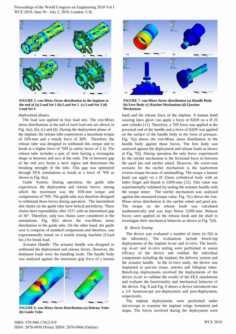
deployment phases.
The load was applied in four load sets. The von-Mises
stress distributions at the end of each load sets are shown in
Fig. 5(a), (b), (c) and (d). During the deployment phase of
the implant, the release tube experiences a maximum torque
of 16N-mm and a tensile force of 30N. Therefore, the
release tube was designed to withstand this torque and to
break at a higher force of 70N (a safety factor of 2.3). The
release tube includes a pair of slots having a rectangular
shape in between and arcs at the ends. The in between gap
of the end arcs forms a neck region and determines the
breaking strength of the tube. This gap was optimized
through FEA simulations to break at a force of 70N as
shown in Fig. 6(a).
Guide System: During operation, the guide tube
experiences the deployment and release forces, among
which the maximum was the 16N-mm torque and
compression of 70N. The guide tube was therefore designed
to withstand these forces during operation. The intermittent
slot chains on the guide tube have helical periodicity. These
chains have repeatability after 315° with an intermittent gap
of 36°. Therefore, only two chains were considered in the
simulations. Fig. 6(b) shows the von-Mises stress
distribution in the guide tube. On the other hand, the guide
wire is comprise of standard components and therefore, was
experimentally tested on a tensile testing machine (Lloyd
Inc.) for break load.
Actuator Handle: The actuator handle was designed to
withstand the deployment and release forces. However, the
dominant loads were the handling loads. The handle body
was analysed against the maximum grip force of a human
hand and the release force of the implant. A human hand
wearing latex glove can apply a force of 826N on a Ø 25
mm cylinder [11]. Therefore, a 70N force was applied at the
proximal end of the handle and a force of 826N was applied
on the surface of the handle body in the form of pressure.
Fig. 7(a) shows the von-Mises stress distribution in the
handle body against these forces. The fore body was
analysed against the deployment and release loads as shown
in Fig. 7(b). During operation the only force, experienced
by the ratchet mechanism is the frictional force in between
the pawl pin and ratchet wheel. However, the worst-case
scenario for the ratchet mechanism is the inadvertent
reverse torque because of mishandling. The torque a human
hand can apply on a Ø 25mm cylindrical body with an
index finger and thumb is 520N-mm [12]. This value was
experimentally validated by testing the actuator handle with
the torque meter. The ratchet mechanism was analysed
against this measured torque value. Fig. 7(c) shows the von-
Mises stress distribution in the ratchet wheel and pawl pin.
The torque on the release knob was calculated
mathematically and was kept below 520N-mm. Release
forces were applied on the release knob and the shaft to
investigate their mechanical behavior as shown in Fig. 7(d).
B. Bench Testing
The device was evaluated a number of times (n>50) in
the laboratory. The evaluations include bench-top
deployments of the implant in-air and in-vitro. The bench-
top in-air and in-vitro testing were performed to assess
efficacy of the device and validate the individual
components including the implant, the delivery system and
the actuator handle. In the in-vitro study, the device was
implanted in porcine tissue, arteries and fallopian tubes.
Bench-top deployments involved the deployments of the
device in-air to validate the results of the FEA simulations
and evaluate the functionality and mechanical behavior of
the device. Fig. 8 and Fig. 9 shows a device introduced into
a 5-F hysteroscope pre-deployment and post-deployment,
respectively.
The implant deployments were performed under
microscope to examine the implant wings formation and
shape. The forces involved during the deployment were
FIGURE 5. von-Mises Stress distribution in the Implant at
the end of (a) Load Set 1 (b) Load Set 2 (c) Load Set 3 (d)
Load Set 4
FIGURE 6. von-Mises Stress Distribution (a) Release Tube
(b) Guide Tube
FIGURE 7. von-Mises Stress distribution (a) Handle Body
(b) Fore Body (c) Ratchet Mechanism (d) Ejection
Mechanism
Proceedings of the World Congress on Engineering 2010 Vol I WCE 2010, June 30 - July 2, 2010, London, U.K.
ISBN: 978-988-17012-9-9 ISSN: 2078-0958 (Print); ISSN: 2078-0966 (Online)
WCE 2010

also measured. The torque required to expand the wing slots
to the requisite out-of-plane displacement was measured
using a torque meter by deploying the implant. Therefore,
instead of the actuator, the guide wire was held in the
torque meter and torque was applied on the implant using a
manual handle. The peak value of the torque was recorded
and then compared with predicted values from FEA
simulations. The compression force required to form the
wings was measured using a tensile testing machine (Lloyd
Inc.). For this measurement, a semi deployed implant,
which was only gone through slot expansion, was laser
welded to two pins at both the proximal and distal ends.
These welded pins were then clamped into the jaws of the
tensile testing machine for application of compression force
through the load cell. The compression force achieved
during this study was compared with the values of FEA
simulations. The torque on the release knob was measured
by holding the actuator in the torque meter and clamping
the release tube in between fore body and release shaft.
This measured force was compared with available studies
[12] and FEA simulations.
In-vitro bench testing (n=10) was carried out on both
porcine tissue and fallopian tubes. These tests were
performed to validate the deployment inside tissues against
external loads, i.e. the loading exerted by tissue on the
implant.
C. Xplant Studies
To evaluate the performance of the device in conditions
very similar to in-vivo implementation, in-vitro experiments
were conducted using explanted uteri. These uteri were
removed at hysterectomy for various benign indications at
the University Hospital, Mullingar, Ireland. Explanted uteri
were chosen as the test model as this is most representative
model of the in-vivo situation. These studies (n=7) were
performed to validate the functionality, deliverability and
effectiveness of the device for instant closure of human
fallopian tubes. The device was delivered and deployed
bilaterally into the tubal ostia. A small caliber hysteroscope
with a 5-F operating channel was used to deliver the
implant into the ostium tissue. The uterus was distended
with normal saline and spurt of saline from the fallopian
tubes confirmed the un-obstruction. The hysteroscope was
introduced under direct vision into the uterus and both tubal
opening were observed as shown in Fig. 10(a). After
positioning, the device was guided through the
hysteroscope as shown in Fig. 10(b). On approaching the
tubal ostium, the implant was positioned in the intramural
segment of the fallopian tube until the straight splines at the
implant distal end became invisible as shown in Fig. 10(c).
After optimal placement the implant was deployed and
released from the delivery actuator as shown in Fig. 10(d).
The delivery system was withdrawn and the procedure was
repeated on the contra-lateral tube. After successful
deployment of implants in both tubes, a hydraulic pressure
test of the uterus was performed to verify occlusion of the
fallopian tubes. In this test, saline solution and methylene
blue were introduced into the uterus at a pressure of 300
FIGURE 8. Bench-top Pre-Deployed Device introduced into
5F hysteroscope FIGURE 9. Bench-top Post-Deployed Device introduced
into 5F hysteroscope
FIGURE 10. Hysteroscopic views of Xplant Studies (a)
Tubal Ostia (b) Implant Guide Tip ingoing Left Tubal
Opening (c) Implant optimally placed at Left Tubal ostium
(d) Deployed Implant at Left Tubal Ostium
FIGURE 11. Uterus in Xplant Studies (a) Un-obstructed
Fallopian Tubes Pre-Deployment (b) Occluded Fallopian
Tubes Post-Deployment (c) Hydraulic Pressure Testing
Post-Deployment (d) Deployed Implant in Dissected
Proceedings of the World Congress on Engineering 2010 Vol I WCE 2010, June 30 - July 2, 2010, London, U.K.
ISBN: 978-988-17012-9-9 ISSN: 2078-0958 (Print); ISSN: 2078-0966 (Online)
WCE 2010

mmHg. The pressure was held for 5 minutes to ensure the
blockage of the fallopian tubes. Finally, the ostium and
tubes were dissected to examine the placement and
deployment of the implant in the intramural section of the
ostium. The implant along with some tissue was extracted
to further examine the wing shape, deployed implant and
tissue entrapped.
III. RESULTS AND DISCUSSION
The device for transcervical sterilization presented in this
paper has various advantages over tubal sterilization:
avoiding general anesthesis, no incision in the body, a
clinical procedure and decreased cost. Its main advantage
over other transcervical procedures is the instant
mechanical occlusion to effect female sterilization. The
design of the device, 3D modeling and FEA simulations
were performed using CAD and FEA software. The device
was validated by experimentation and testing. The implant
was fabricated using laser cutting machine (LPL Stent
Cutter). The fabricated implant was deployed under
microscope and its mechanical behavior was studied. The
wing profile of the deployed implants was measured using
video inspection probe and its profile was reconstructed
using Pro/E. This experimentally measured profile of the
wings was superimposed on the profile obtained from FEA
simulations and compared. The standard error of mean of
the difference of experimental and simulated profile was
0.003543 and the maximum percent error was 3.129%.
The forces required to deploy implants were validated
experimentally on the test bench. On application of 16.0N-
mm moment in ANSYS WB simulations, a 0.353 mm out-
of-plane displacement in implant slots was obtained at the
end of load set 1. A comparable 15.4N-mm was measured
experimentally using a torque meter when same amount of
radial expansion (from Ø1.535mm to Ø2.241mm) in
implant slots was achieved. In order to plastically deform
these expanded implant slots, a force of 25.4 N was
measured from tensile testing which is comparable to a
force of 25 N obtained from the FEA simulations. In-house
in-vitro and mechanical bench testing validated the
mechanical behavior and functional aspects of the implant.
In-vitro deployments (n=7) of the implant into human
explanted uteri were performed. Fig. 11(a) shows the un-
obstructed fallopian tubes before deployment. The occluded
fallopian tube is shown in Fig 11(b). As expected, the
device had successfully occluded the fallopian tubes in all
uteri. Immediately after the bilateral deployment of device
in the uteri, the hydraulic pressure tests using saline water
and methylene blue at pressure of 300 mmHg were
performed. It is apparent from Fig. 11(c) that there was no
leakage during these hydraulic pressure testing. These uteri
were dissected after hydraulic pressure testing and the
implant along with some tissue was examined under
microscope to further investigate the implant wings shape,
deployed implant and tissue trapped as shown in Fig 11(d).
It was observed in dissection that there was no indication of
methylene blue after distal wings of the implant. This
demonstrates the capability of the device to achieve instant
occlusion of the fallopian tubes even at a pressure of 300
mmHg.
The statistical methods used to analyse and report the
results of explants studies were the statistical summaries of
results and tabulation of the data. Occlusion of each
fallopian tube was treated as an individual event
representing 0 or 1 for ―no‖ or ―yes‖ occlusion respectively.
Bilateral deployments of the implant were attempted in 7
explant studies. Successful instant occlusion was achieved
in 14 out of 14 (100%) fallopian tubes. Since there were
zero failures among 7 explanted uteri, statistical
significance was not established because of zero numerator
problems. However, these effective in-vitro tests are
important in the development of the device as they provide
a clear indication of the device’s capabilities and
weaknesses prior to commencing in-vivo verification and
validation activities. Data generated from investigations in
explanted uteri verified the efficacy of the implant as well
as minimizing the risk to patients participating in in-vivo
clinical studies. Further development work is underway in
preparation for ―first-in-man‖ clinical trials. As an overall
conclusion, this implant is effective, consistent and feasible
for hysteroscopic occlusion of fallopian tubes.
ACKNOWLEDGEMENTS
The authors thank Vasorum /Alta Science team for their
support. The authors thank Dr. Michael Gannon from the
Midlands Regional Hospital, Mullingar, Ireland for the
arrangement and performing in-vitro studies in human uteri.
REFERENCES
[1] Thurkow, A. L., Hysteroscopic sterilization: away with the laparoscope? International Congress Series, 1279, 184-188 (2005)
[2] Magos, A. and Chapman, L., Hysteroscopic tubal sterilization;
Obstet. Gynecol. Clin. North Am., 31, 31705-31719 (2004) [3] Abbott, J., Transcervical sterilization, Best Pract. Res. Clin. Obstet.
Gynaecol., 19, 743-756 (2005)
[4] Brumsted, J. R., Shirk, G., Soderling, M. J. and Reed, T., Attempted transcervical occlusion of the fallopian tube with the Nd:YAG laser,
Obstet. Gynecol., 77, 327-328 (1991)
[5] Carr-Brendel, V. E., Stewart, D. R., Harrington, D. C., Leal, J. G. G. and Vancaillie, T., A new transcervical sterilization procedure:
results of a pilot implant study in humans, Obstet. Gynecol., 97, 8
(2001)
[6] Carr-Brendel, V. E., Stewart, D. R., Harrington, D. C., Dhaka, V. K.,
Breining, P. M. and Vancaillie, T., A new transcervical sterilization
procedure—6-month preclinical results, Obstet. Gynecol., 97, 15-16 (2001)
[7] McSwain, H. and Brodie, M. F., Fallopian Tube Occlusion, An
Alternative to Tubal Ligation, Tech. Vasc. Interv. Radiol., 9, 24-29 (2006)
[8] Ubeda, A., Labastida, R. and Dexeus, S., Essure®: a new device for
hysteroscopic tubal sterilization in an outpatient setting, Fertil. Steril., 82, 196-199 (2004)
[9] Cooper, J. M., Carignan, C. S., Cher, D. and Kerin, J. F., Microinsert
nonincisional hysteroscopic sterilization, Obstet. Gynecol., 102, 59-67 (2003)
[10] Rehan, M., Coleman, J. E. and Olabi, A. G., Novel Implant for
Transcervical Sterilization, manuscript submitted, Journal of Bioscience and Bioengineering (2009)
[11] BryanWimer, Ren G. Dong, Daniel E.Welcome, ChristopherWarren,
ThomasW. McDowell, Development of a new dynamometer for measuring grip strength applied on a cylindrical handle, Medical
Engineering & Physics, 31, 695–704 (2009)
[12] Kong, Yong-Ku, Lowe B. D., Evaluation of handle diameters and orientations in a maximum torque task, , International Journal of
Industrial Ergonomics, 35, 1073–1084 (2005)
Proceedings of the World Congress on Engineering 2010 Vol I WCE 2010, June 30 - July 2, 2010, London, U.K.
ISBN: 978-988-17012-9-9 ISSN: 2078-0958 (Print); ISSN: 2078-0966 (Online)
WCE 2010