Novel Electrospun Polylactic Acid Nanocomposite Fiber Mats with ...
19
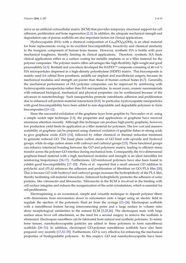
polymers Article Novel Electrospun Polylactic Acid Nanocomposite Fiber Mats with Hybrid Graphene Oxide and Nanohydroxyapatite Reinforcements Having Enhanced Biocompatibility Chen Liu 1 , Hoi Man Wong 2 , Kelvin Wai Kwok Yeung 2 and Sie Chin Tjong 1, * 1 Department of Physics and Materials Science, City University of Hong Kong, Tat Chee Avenue, Kowloon, Hong Kong, China; [email protected] 2 Department of Orthopedics and Traumatology, Li Ka Shing Faculty of Medicine, The University of Hong Kong, Hong Kong, China; [email protected] (H.M.W.); [email protected] (K.W.K.Y.) * Correspondence: [email protected]; Tel.: +852-3442-7702 Academic Editors: Naozumi Teramoto and Takashi Tsujimoto Received: 2 June 2016; Accepted: 3 August 2016; Published: 8 August 2016 Abstract: Graphene oxide (GO) and a nanohydroxyapatite rod (nHA) of good biocompatibility were incorporated into polylactic acid (PLA) through electrospinning to form nanocomposite fiber scaffolds for bone tissue engineering applications. The preparation, morphological, mechanical and thermal properties, as well as biocompatibility of electrospun PLA scaffolds reinforced with GO and/or nHA were investigated. Electron microscopic examination and image analysis showed that GO and nHA nanofillers refine the diameter of electrospun PLA fibers. Differential scanning calorimetric tests showed that nHA facilitates the crystallization process of PLA, thereby acting as a nucleating site for the PLA molecules. Tensile test results indicated that the tensile strength and elastic modulus of the electrospun PLA mat can be increased by adding 15 wt % nHA. The hybrid nanocomposite scaffold with 15 wt % nHA and 1 wt % GO fillers exhibited higher tensile strength amongst the specimens investigated. Furthermore, nHA and GO nanofillers enhanced the water uptake of PLA. Cell cultivation, 3-(4,5-dimethylthiazol-2-yl)-2,5-diphenyltetrazolium bromide (MTT) and alkaline phosphatase tests demonstrated that all of the nanocomposite scaffolds exhibit higher biocompatibility than the pure PLA mat, particularly for the scaffold with 15 wt % nHA and 1 wt % GO. Therefore, the novel electrospun PLA nanocomposite scaffold with 15 wt % nHA and 1 wt % GO possessing a high tensile strength and modulus, as well as excellent cell proliferation is a potential biomaterial for bone tissue engineering applications. Keywords: polylactic acid; electrospinning; graphene oxide; hydroxyapatite; nanocomposites; biocompatibility 1. Introduction The development of polymer scaffolds with good bioactivity and biocompatibility is considered of significant technical and clinical importance due to a large increase in ageing populations, and the number of patients suffering from bone disease, trauma, traffic accident and sports activity. Nowadays, bone diseases (e.g., osteoporosis, scoliosis and tumor) and injuries cause a significant public health problem. Bone tissue generally exhibits excellent regeneration capacity and can repair itself upon injury. However, this self-healing is impaired if trauma is serious and exceeds a certain size. Tissue engineering integrates engineering and biomedical approaches to develop biocompatible scaffolds by seeding cells on their surfaces for achieving bone tissue repair and reconstruction. The aim is to restore the functions of damaged bone tissues and defects and to promote integration with the host tissue [1]. The scaffolds Polymers 2016, 8, 287; doi:10.3390/polym8080287 www.mdpi.com/journal/polymers
Transcript of Novel Electrospun Polylactic Acid Nanocomposite Fiber Mats with ...
polymers
Article
Novel Electrospun Polylactic Acid NanocompositeFiber Mats with Hybrid Graphene Oxide andNanohydroxyapatite Reinforcements HavingEnhanced Biocompatibility
Chen Liu 1, Hoi Man Wong 2, Kelvin Wai Kwok Yeung 2 and Sie Chin Tjong 1,*1 Department of Physics and Materials Science, City University of Hong Kong, Tat Chee Avenue, Kowloon,
Hong Kong, China; [email protected] Department of Orthopedics and Traumatology, Li Ka Shing Faculty of Medicine, The University of Hong
Kong, Hong Kong, China; [email protected] (H.M.W.); [email protected] (K.W.K.Y.)* Correspondence: [email protected]; Tel.: +852-3442-7702
Academic Editors: Naozumi Teramoto and Takashi TsujimotoReceived: 2 June 2016; Accepted: 3 August 2016; Published: 8 August 2016
Abstract: Graphene oxide (GO) and a nanohydroxyapatite rod (nHA) of good biocompatibilitywere incorporated into polylactic acid (PLA) through electrospinning to form nanocomposite fiberscaffolds for bone tissue engineering applications. The preparation, morphological, mechanicaland thermal properties, as well as biocompatibility of electrospun PLA scaffolds reinforced withGO and/or nHA were investigated. Electron microscopic examination and image analysis showedthat GO and nHA nanofillers refine the diameter of electrospun PLA fibers. Differential scanningcalorimetric tests showed that nHA facilitates the crystallization process of PLA, thereby acting asa nucleating site for the PLA molecules. Tensile test results indicated that the tensile strength andelastic modulus of the electrospun PLA mat can be increased by adding 15 wt % nHA. The hybridnanocomposite scaffold with 15 wt % nHA and 1 wt % GO fillers exhibited higher tensile strengthamongst the specimens investigated. Furthermore, nHA and GO nanofillers enhanced the wateruptake of PLA. Cell cultivation, 3-(4,5-dimethylthiazol-2-yl)-2,5-diphenyltetrazolium bromide (MTT)and alkaline phosphatase tests demonstrated that all of the nanocomposite scaffolds exhibit higherbiocompatibility than the pure PLA mat, particularly for the scaffold with 15 wt % nHA and 1 wt %GO. Therefore, the novel electrospun PLA nanocomposite scaffold with 15 wt % nHA and 1 wt % GOpossessing a high tensile strength and modulus, as well as excellent cell proliferation is a potentialbiomaterial for bone tissue engineering applications.
Keywords: polylactic acid; electrospinning; graphene oxide; hydroxyapatite;nanocomposites; biocompatibility
1. Introduction
The development of polymer scaffolds with good bioactivity and biocompatibility is consideredof significant technical and clinical importance due to a large increase in ageing populations, and thenumber of patients suffering from bone disease, trauma, traffic accident and sports activity. Nowadays,bone diseases (e.g., osteoporosis, scoliosis and tumor) and injuries cause a significant public healthproblem. Bone tissue generally exhibits excellent regeneration capacity and can repair itself upon injury.However, this self-healing is impaired if trauma is serious and exceeds a certain size. Tissue engineeringintegrates engineering and biomedical approaches to develop biocompatible scaffolds by seeding cellson their surfaces for achieving bone tissue repair and reconstruction. The aim is to restore the functionsof damaged bone tissues and defects and to promote integration with the host tissue [1]. The scaffolds
Polymers 2016, 8, 287; doi:10.3390/polym8080287 www.mdpi.com/journal/polymers
Polymers 2016, 8, 287 2 of 19
serve as an artificial extracellular matrix (ECM) that provides temporary structural support for celladhesion, proliferation and bone regeneration [2,3]. In addition, the adequate mechanical strength anddegradation rate of porous scaffolds are also important factors for clinical applications.
Hydroxyapatite (HA) with a chemical composition of Ca10(PO4)6(OH)2 is an ideal materialfor bone replacements owing to its excellent biocompatibility, bioactivity and chemical similarityto the inorganic component of human bone tissues. However, synthetic HA is brittle with poormechanical toughness, thereby limiting its clinical applications. Therefore, synthetic HA findsclinical applications either as a surface coating for metallic implants or as a filler material for thepolymer composites. The polymer matrix offers advantages like high flexibility, light weight and goodprocessability [4,5]. Bonfield and coworkers developed the HAPEX™ composite consisting of 40 vol %HA microparticles dispersed in a high-density polyethylene (HDPE) matrix. This biocomposite ismainly used for orbital floor prosthesis, middle ear implant and maxillofacial surgery, because itsmechanical modulus and strength are poorer than those of human cortical bones [6,7]. Generally,the mechanical performance of HA/polymer composites can be improved by reinforcing withhydroxyapatite nanoparticles rather than HA microparticles. In recent years, ceramic nanomaterialswith enhanced biological, mechanical and physical properties can be synthesized because of theadvances in nanotechnology. Such nanoparticles promote osteoblastic adhesion and proliferationdue to enhanced cell protein-material interactions [8,9]. In particular, hydroxyapatite nanoparticleswith good biocompatibility have been added to non-degradable and degradable polymers to formbiocomposites [10–12].
Since the successful exfoliation of the graphene layer from graphite by Novoselov et al. usinga simple scotch tape technique [13], the properties and applications of graphene have receivedenormous attention recently. Although this technique can produce high purity graphene, however,low production yield limits its application as a filler material for polymers. The low cost and massivescalability of graphene can be prepared using chemical oxidation of graphite flakes in strong acidsto give graphene oxide (GO) [14], followed by either chemical or thermal reduction treatmentto generate reduced GO. The basal plane carbon atoms of GO bind with epoxide and hydroxylgroups, while its edge carbon atoms with carboxyl and carbonyl groups [15]. Those functional groupscan enhance interfacial bonding between the GO and polymeric matrix, leading to efficient stresstransfer across the polymer-GO interface during mechanical tests. Consequently, the two-dimensionalgraphene-based material with a high mechanical modulus and strength is an ideal nanofiller forreinforcing biopolymers [16,17]. Furthermore, GO-reinforced polymers have also been found toexhibit good biocompatibility [17–20]. Pinto et al. reported that a small amount GO addition topolylactic acid (PLA) enhances the adhesion and proliferation of fibroblast on GO/PLA film [20].This is because GO with hydroxyl and carboxyl groups increases the hydrophilicity of the PLA film,thereby facilitating cell-material interactions. Enhanced hydrophilicity promotes the adhesion of someproteins, like vitronectin and fibronectin. Fibronectin in the ECM is involved in the binding withcell surface integrins and induces the reorganization of the actin cytoskeleton, which is essential forcell proliferation.
Electrospinning is an economical, simple and versatile technique to deposit polymer fiberswith dimensions from micrometers down to nanometers onto a target using an electric field toregulate the ejection of the polymeric fluid jet from the syringe [21–24]. Electrospun scaffoldswith a nanofibrous feature having interconnecting pores and a large surface to volume ratioshow morphological similarities to the natural ECM [3,25,26]. The electrospun mats with largesurface areas favor cell attachment, so the need for a second surgery to remove the scaffolds iseliminated. Electrospun nanofibers can be fabricated from natural and synthetic polymers. To mimicbone tissues, nanohydroxyapatite particles are added to these polymers to form nanofibrousscaffolds [26–31]. In addition, electrospun GO-polymer nanofibrous scaffolds have also beenprepared very recently [17,32–35]. Furthermore, GO is very effective for enhancing the mechanicalproperties of biodegradable polymers. In this respect, GO and nanohydroxyapatite have been
Polymers 2016, 8, 287 3 of 19
incorporated into natural polysaccharide-based polymers, such as chitosan and alginate [36,37].Natural polymers generally suffer from low mechanical strength especially in the presence ofwater and humid environments. Comparing to starch-based polymers, synthetic polylactic acid(PLA) exhibits better mechanical properties. This polymer degrades through hydrolysis under thede-esterification mechanism [38–41]. Thus, it is a promising biomaterial for tissue engineering andregenerative medicine [42–44]. Recently, Ma et al. carried out a preliminary study on the structure andshort-term 3-(4,5-dimethylthiazol-2-yl)-2,5-diphenyltetrazolium bromide (MTT) tests of electrospunPLA nanofibers reinforced with GO and hydroxyapatite nanoparticles [45]. Their MTT results indicatedthat both GO and hydroxyapatite nanoparticles enhance murine MC3T3-E1 cell proliferation for a24 h test. However, the cell proliferation of their hybrid scaffolds is poorer than that of PLA after 48 h.The aims of our work are to prepare electrospun PLA-nanohydroxyapatite rod (nHA)-GO nanofibrousmats and to study their mechanical and thermal properties, as well as long-term biocompatibility.
2. Materials and Methods
2.1. Materials
PLA was purchased from Shenzhen Bright China Inc. (Shenzhen, China). Nanohydroxyapatiterod (nHA) powders were obtained commercially from Nanjing Emperor Nano Materials (Nanjing,China). Graphite flakes were bought from Sigma-Aldrich Inc. (Saint Louis, MO, USA). All reagentssuch as N,N-dimethylformamide (DMF), dichloromethane (DCM), K2MnO4, NaNO3, etc., were usedas received.
2.2. Preparation of Graphene Oxide (GO)
Graphene oxide (GO) was prepared from the chemical oxidation of graphite flakes followinga modified Hummers process. Briefly, graphite flakes were firstly added into concentrated H2SO4
with NaNO3 and stirred in an ice bath for 2 h. Subsequently, K2MnO4 was added to the mixedsolution slowly. The reaction was stirred for 2 days. After that, H2O2/H2O (2.5:100 mL) was addedand cooled in the ice bath. The product was centrifuged and the supernatant was decanted away.The remaining solid material was then washed with 3% HCl and water three times, respectively,followed by freeze drying.
2.3. Electrospun Nanofibrous Mats
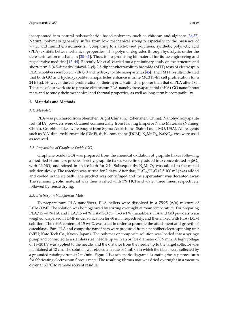
To prepare pure PLA nanofibers, PLA pellets were dissolved in a 75:25 (v/v) mixture ofDCM/DMF. The solution was homogenized by stirring overnight at room temperature. For preparingPLA/15 wt % HA and PLA/15 wt % HA-xGO (x = 1–3 wt %) nanofibers, HA and GO powders wereweighed, dispersed in DMF under sonication for 60 min, respectively, and then mixed with PLA/DCMsolution. The nHA content of 15 wt % was used in order to promote the attachment and growth ofosteoblasts. Pure PLA and composite nanofibers were produced from a nanofiber electrospinning unit(NEU; Kato Tech Co., Kyoto, Japan). The polymer or composite solution was loaded into a syringepump and connected to a stainless steel needle tip with an orifice diameter of 0.9 mm. A high voltageof 18–20 kV was applied to the needle, and the distance from the needle tip to the target collector wasmaintained at 12 cm. The solution was ejected at a rate of 1 mL/h in which the fibers were collected bya grounded rotating drum at 2 m/min. Figure 1 is a schematic diagram illustrating the step proceduresfor fabricating electrospun fibrous mats. The resulting fibrous mat was dried overnight in a vacuumdryer at 60 ˝C to remove solvent residue.
Polymers 2016, 8, 287 4 of 19Polymers 2016, 8, 287 4 of 18
Figure 1. Schematic illustration showing the preparation of electrospun nanocomposite fibrous mats. PLA, polylactic acid; GO, Graphene Oxide; nHA, nanohydroxyapatite rod; DCM, dichloromethane; DMF, N,N-dimethylformamide.
2.4. Material Characterization
The morphology of nHA was observed in a transmission electron microscope (TEM; Philips FEG CM 20, Philips, Amsterdam, The Netherlands). The final GO product was characterized using an atomic force microscope (AFM; Veeco Nanoscope V, Veeco Instruments Inc., Plainview, NY, USA) and a Raman spectrometer (LabRam, JY/Horiba, Edison, NJ, USA). The morphology of electrospun fiber mats was examined in a scanning electron microscope (SEM; Jeol JSM-820, Jeol industries, Tokyo, Japan) and TEM. The diameter and porosity of the fibers were analyzed from the SEM images by image analysis using ImageJ software (ImageJ, Bethesda, MD, USA). Porosity was evaluated by means of segmenting grey scale images under auto-threshold mode to recognize the top layer of the fiber. Fourteen measurements were made for each sample for its porosity evaluation. Fourier transform infrared (FTIR) spectra of nanofibers were collected with a Perkin Elmer spectrometer (16 PC, Perkin-Elmer Corp., Boston, MA, USA) in the wavenumber range of 400–2000 cm−1 with a resolution of 4 cm−1.
Differential scanning calorimetry (DSC, TA Instruments, New Castle, DE, USA) measurements were conducted with a TA Instruments Model 2910 under a protective nitrogen atmosphere. The specimens were first heated to 200 °C, maintained at this temperature for 3 min and cooled to 30 °C at a rate of 10 °C/min. A second heating scan to 200 °C at the same rate was subsequently initiated.
Tensile properties of electrospun fiber mats were measured with an Instron tester (Model 5567, Instron Corp., Norwood, MA, USA) using a load cell of 50 N at a crosshead speed of 10 mm/min at room temperature. All fibrous mats were cut into standard rectangular specimens of 50 mm in length and 10 mm in width [46,47]. Stress-strain curves of fibrous mats were recorded. Five samples of each composition were tested, and the average value was reported.
2.5. Water Uptake
PLA and its nanocomposite fibrous mats were cut into specimens of 20 mm in length and 10 mm in width and weighed before immersing in a simulated body fluid (SBF). This solution was prepared by dissolving certain amounts of chemical reagents, including Na+ (142 mM) , K+ (5 mM), Ca2+ (2.5 mM), Mg2+ (1.5 mM), Cl− (147.8 mM), HCO3− (4.2 mM), HPO4− (1 mM) and SO42− (0.5 mM). It was buffered to a pH of 7.4 using tris-(hydroxymethyl)-aminomethane and 1 M HCl [48]. The fibers were rinsed with deionized water, wiped gently with filter paper and then weighed before immersion in the solution. After immersion in SBF at room temperature (23 °C) for 1, 3 and 14 days,
Figure 1. Schematic illustration showing the preparation of electrospun nanocomposite fibrous mats.PLA, polylactic acid; GO, Graphene Oxide; nHA, nanohydroxyapatite rod; DCM, dichloromethane;DMF, N,N-dimethylformamide.
2.4. Material Characterization
The morphology of nHA was observed in a transmission electron microscope (TEM; Philips FEGCM 20, Philips, Amsterdam, The Netherlands). The final GO product was characterized using anatomic force microscope (AFM; Veeco Nanoscope V, Veeco Instruments Inc., Plainview, NY, USA) anda Raman spectrometer (LabRam, JY/Horiba, Edison, NJ, USA). The morphology of electrospun fibermats was examined in a scanning electron microscope (SEM; Jeol JSM-820, Jeol industries, Tokyo,Japan) and TEM. The diameter and porosity of the fibers were analyzed from the SEM images byimage analysis using ImageJ software (ImageJ, Bethesda, MD, USA). Porosity was evaluated bymeans of segmenting grey scale images under auto-threshold mode to recognize the top layer ofthe fiber. Fourteen measurements were made for each sample for its porosity evaluation. Fouriertransform infrared (FTIR) spectra of nanofibers were collected with a Perkin Elmer spectrometer (16 PC,Perkin-Elmer Corp., Boston, MA, USA) in the wavenumber range of 400–2000 cm´1 with a resolutionof 4 cm´1.
Differential scanning calorimetry (DSC, TA Instruments, New Castle, DE, USA) measurementswere conducted with a TA Instruments Model 2910 under a protective nitrogen atmosphere.The specimens were first heated to 200 ˝C, maintained at this temperature for 3 min and cooled to 30 ˝Cat a rate of 10 ˝C/min. A second heating scan to 200 ˝C at the same rate was subsequently initiated.
Tensile properties of electrospun fiber mats were measured with an Instron tester (Model 5567,Instron Corp., Norwood, MA, USA) using a load cell of 50 N at a crosshead speed of 10 mm/min atroom temperature. All fibrous mats were cut into standard rectangular specimens of 50 mm in lengthand 10 mm in width [46,47]. Stress-strain curves of fibrous mats were recorded. Five samples of eachcomposition were tested, and the average value was reported.
2.5. Water Uptake
PLA and its nanocomposite fibrous mats were cut into specimens of 20 mm in length and 10 mmin width and weighed before immersing in a simulated body fluid (SBF). This solution was prepared bydissolving certain amounts of chemical reagents, including Na+ (142 mM) , K+ (5 mM), Ca2+ (2.5 mM),Mg2+ (1.5 mM), Cl´ (147.8 mM), HCO3
´ (4.2 mM), HPO4´ (1 mM) and SO4
2´ (0.5 mM). It wasbuffered to a pH of 7.4 using tris-(hydroxymethyl)-aminomethane and 1 M HCl [48]. The fibers wererinsed with deionized water, wiped gently with filter paper and then weighed before immersion in
Polymers 2016, 8, 287 5 of 19
the solution. After immersion in SBF at room temperature (23 ˝C) for 1, 3 and 14 days, the specimenswere removed from the solution, rinsed with deionized water and weighed. The water uptake wascalculated using the following equation:
Water uptake p%q “ 100ˆWwet ´W0
W0(1)
where Wwet is the weight of the wet fiber mat and W0 is the initial weight of the sample prior to immersion.Six samples of each composition were tested, and their mean standard deviation (˘SD) was determined.
2.6. Cell Cultivation and Viability
Human osteoblast cell line Saos-2 was cultured in Dulbecco’s Modified Eagle Medium(DMEM; Thermo Scientific, Pittsburgh, PA, USA) with 10% fetal bovine serum, 100 mg/mL ofstreptomycin and 100 U/mL of penicillin. The fibrous mats were sliced into round disks of 6 mm indiameter and sterilized with 70% ethanol before cell cultivation. By rinsing three times with sterilephosphate-buffered saline (PBS) solution, the samples were dipped in DMEM medium overnightand then placed into the 96-well plates in triplicate followed by seeding with 100 µL cell suspensioncontaining 1 ˆ 104 cells per well. These plates were placed in an incubator at 37 ˝C with humidifiedatmosphere of 95% air and 5% CO2 for 5 and 7 days, respectively. At the end of each time point, sampleswere taken out from the wells and rinsed with PBS solution twice to remove the unattached cells, fixedwith 10% formaldehyde solution and dehydrated in a series of ethanol solutions (30, 50, 70, 90, 100 vol %)followed with air drying. Finally, samples were coated with a thin gold film for SEM observation.
The cell viability of PLA, PLA/15%nHA and PLA/15%nHA-GO fibrous mats wasassessed with 3-(4,5-dimethylthiazol-2-yl)-2,5-diphenyltetrazolium bromide (MTT) colorimetric assay.After culturing the samples with the 100 µL cell suspension at 1 ˆ 104 cells/well, the plates wereincubated at 37 ˝C in a humidified atmosphere of 95% air/5% CO2 for 3, 7 and 10 days. The DMEMmedium was changed every three days. After each incubation time, the medium was aspirated,and 100 µL of MTT solution were added into each well to give insoluble formazan crystals. Priorto adding 100 µL of 10% sodium dodecyl sulfate (SDS) in 0.01 M hydrochloric acid to dissolve thecrystals, the plates were incubated for another 4 h. The optical absorbance of the solubilized formazanwas analyzed with a multimode detector (Beckman Coulter DTX 880, Beckman Coulter Inc., Fullerton,CA, USA) at a wavelength of 570 nm with a reference wavelength of 640 nm. The mean standarddeviation (˘SD) of five replicates was determined. A two-way analysis of variance (ANOVA) wasused to evaluate the statistical data; a p-value of 0.05 was selected as the level of significance.
2.7. Alkaline Phosphatase
Alkaline phosphatase is an enzyme secreted by osteoblasts acting as the marker to reveal earlierosteoblastic differentiation for bone tissue mineralization. Samples were sliced into disks of 14 mm indiameter, sterilized with ethanol, rinsed with PBS and placed in the 24-well plate. Then, 104 cells/wellwere introduced to the culture plate followed by incubation at 37 ˝C in an atmosphere of 95% air/5%CO2 for 3, 7 and 14 days. The culture medium was refreshed every three days. At the end of eachincubation period, the cells were washed with PBS three times and lysed with 0.1% Triton X-100at 4 ˝C for 15 min. The cell lysates were then transferred to 1.5 mL tubes and centrifuged at 4 ˝Cfor 10 min. Subsequently, 10 µL of the supernatant of each sample were transferred to a 96-wellplate. The alkaline phosphatase (ALP) activity was determined with a commercial assay kit (No. 2900,Stanbio Laboratory, Boerne, TX, USA) employing colorless p-nitrophenyl phosphate (pNPP) as aphosphatase substrate. In the process, ALP enzyme hydrolyzed the substrate to yellow p-nitrophenoland phosphate. The absorbance was recorded with a multimode detector at a wavelength of 405 nm.The ALP activity was normalized to the protein level of each sample lysate measured by the Bio-RadProtein Assay (Bio-Rad, Hercules, CA, USA). A two-way ANOVA was used to analyze the statisticaldata; a p-value of 0.05 was selected as the level of significance.
Polymers 2016, 8, 287 6 of 19
3. Results and Discussion
3.1. Nanomaterial and Electrospun Fiber Features
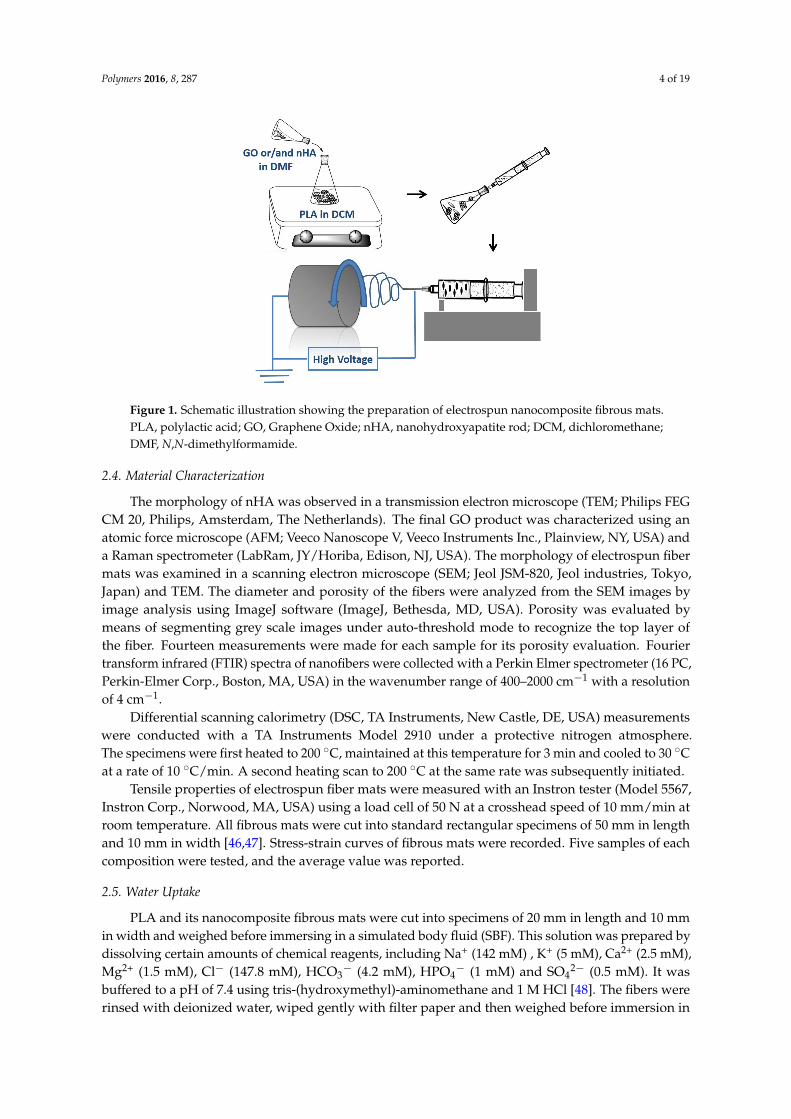
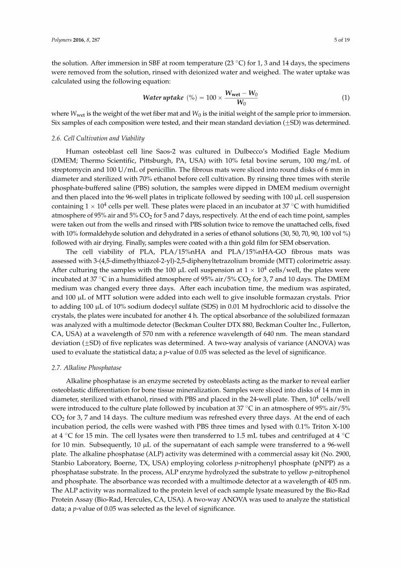
The transmission electron microscopy image revealed nHA exhibiting a width of 20 nm and alength of 100 nm (Figure 2). Figure 3a shows the AFM image of GO deposited as a monolayer sheetonto a silicon substrate, along with its height profile. The thickness of the GO sheet is 1 nm, but someregions display a height profile over 1 nm due to the oxygenated groups of GO. The Raman spectrumof GO shows the presence of the D band (1340 cm´1) and the G band (1595 cm´1) (Figure 3b). The Dband is related to the presence of the defect created by the oxygenated functional groups on the carbonbasal plane, and the G band is due to the ordered sp2-bonded carbon atoms [49]. By contrast, graphiteflake exhibits a sharp G band at 1580 cm´1 and a weak D band (1340 cm´1) due to disorders associatedwith strong C–C bonding and impurity [50]. Furthermore, the G band in GO is shifted to a higherwave number (1595 cm´1) due to the oxygenation of graphite [51].
Polymers 2016, 8, 287 6 of 18
3. Results and Discussion
3.1. Nanomaterial and Electrospun Fiber Features
The transmission electron microscopy image revealed nHA exhibiting a width of 20 nm and a length of 100 nm (Figure 2). Figure 3a shows the AFM image of GO deposited as a monolayer sheet onto a silicon substrate, along with its height profile. The thickness of the GO sheet is 1 nm, but some regions display a height profile over 1 nm due to the oxygenated groups of GO. The Raman spectrum of GO shows the presence of the D band (1340 cm−1) and the G band (1595 cm−1) (Figure 3b). The D band is related to the presence of the defect created by the oxygenated functional groups on the carbon basal plane, and the G band is due to the ordered sp2-bonded carbon atoms [49]. By contrast, graphite flake exhibits a sharp G band at 1580 cm−1 and a weak D band (1340 cm−1) due to disorders associated with strong C–C bonding and impurity [50]. Furthermore, the G band in GO is shifted to a higher wave number (1595 cm−1) due to the oxygenation of graphite [51].
Figure 2. TEM image of nanohydroxyapatite rod (nHA).
Figure 3. (a) AFM image of GO with height profile across a scan line and (b) Raman spectra of GO and graphite.
Figure 2. TEM image of nanohydroxyapatite rod (nHA).
Polymers 2016, 8, 287 6 of 18
3. Results and Discussion
3.1. Nanomaterial and Electrospun Fiber Features
The transmission electron microscopy image revealed nHA exhibiting a width of 20 nm and a length of 100 nm (Figure 2). Figure 3a shows the AFM image of GO deposited as a monolayer sheet onto a silicon substrate, along with its height profile. The thickness of the GO sheet is 1 nm, but some regions display a height profile over 1 nm due to the oxygenated groups of GO. The Raman spectrum of GO shows the presence of the D band (1340 cm−1) and the G band (1595 cm−1) (Figure 3b). The D band is related to the presence of the defect created by the oxygenated functional groups on the carbon basal plane, and the G band is due to the ordered sp2-bonded carbon atoms [49]. By contrast, graphite flake exhibits a sharp G band at 1580 cm−1 and a weak D band (1340 cm−1) due to disorders associated with strong C–C bonding and impurity [50]. Furthermore, the G band in GO is shifted to a higher wave number (1595 cm−1) due to the oxygenation of graphite [51].
Figure 2. TEM image of nanohydroxyapatite rod (nHA).
Figure 3. (a) AFM image of GO with height profile across a scan line and (b) Raman spectra of GO and graphite.
Figure 3. (a) AFM image of GO with height profile across a scan line and (b) Raman spectra of GOand graphite.

Polymers 2016, 8, 287 7 of 19
Figure 4a–c is the representative SEM micrographs showing the morphologies of neat PLA,PLA/15%nHA and PLA/15%nHA-3%GO fibrous mats. PLA displays a relatively smooth featurehaving an average fiber diameter of 786 ˘ 189 nm, as determined by ImageJ software (Figure S1a).The surface of the PLA/15%nHA nanocomposite mat is somewhat rougher than pure PLA. The meandiameter of PLA/15%nHA nanocomposite fibers is 563 ˘ 196 nm (Figure S1b). The addition of15% nHA to PLA reduces the diameter of fibers slightly. This is due to the reduction of polymerconcentration and the change of solution viscosity by adding 15% nHA [52]. By incorporating 3%GO to the PLA/15%nHA, the diameter of the composite fibers further decreases to 412 ˘ 240 nm(Figure S1c). An agglomeration of 15% nHA and GO at the needle tip would reduce the effectiveorifice diameter of the needle, thereby producing nanofibers with a finer diameter [53]. Furthermore,porosity is another key factor for ideal scaffolds for bone regeneration. The results of porosity and fiberdiameter of all fibrous mats as determined by ImageJ software are tabulated in Table 1.
Polymers 2016, 8, 287 7 of 18
Figure 4a–c is the representative SEM micrographs showing the morphologies of neat PLA, PLA/15%nHA and PLA/15%nHA-3%GO fibrous mats. PLA displays a relatively smooth feature having an average fiber diameter of 786 ± 189 nm, as determined by ImageJ software (Figure S1a). The surface of the PLA/15%nHA nanocomposite mat is somewhat rougher than pure PLA. The mean diameter of PLA/15%nHA nanocomposite fibers is 563 ± 196 nm (Figure S1b). The addition of 15% nHA to PLA reduces the diameter of fibers slightly. This is due to the reduction of polymer concentration and the change of solution viscosity by adding 15% nHA [52]. By incorporating 3% GO to the PLA/15%nHA, the diameter of the composite fibers further decreases to 412 ± 240 nm (Figure S1c). An agglomeration of 15% nHA and GO at the needle tip would reduce the effective orifice diameter of the needle, thereby producing nanofibers with a finer diameter [53]. Furthermore, porosity is another key factor for ideal scaffolds for bone regeneration. The results of porosity and fiber diameter of all fibrous mats as determined by ImageJ software are tabulated in Table 1.
Figure 4. SEM micrographs of electrospun (a) PLA, (b) PLA/15%nHA and (c) PLA/15%nHA-3%GO fibrous mats.
Table 1. Average diameter and porosity of electrospun PLA and its nanocomposite fibrous mats.
Specimen Average diameter (nm) Porosity (%)
PLA 786 ± 189 70.52 PLA/15%nHA 563 ± 196 74.52
PLA/15%nHA-1%GO 516 ± 206 75.58 PLA/15%nHA-2%GO 502 ± 213 76.19 PLA/15%nHA-3%GO 412 ± 240 77.96
Polymer nanocomposites are generally reinforced with low nanofiller contents, say 1–3 wt % for achieving the desired functional properties [54–57]. In the case of biocomposites for bone replacement and regeneration applications, higher nHA content, i.e., 15–18 wt %, is needed to
Figure 4. SEM micrographs of electrospun (a) PLA; (b) PLA/15%nHA and (c) PLA/15%nHA-3%GOfibrous mats.
Table 1. Average diameter and porosity of electrospun PLA and its nanocomposite fibrous mats.
Specimen Average diameter (nm) Porosity (%)
PLA 786 ˘ 189 70.52PLA/15%nHA 563 ˘ 196 74.52
PLA/15%nHA-1%GO 516 ˘ 206 75.58PLA/15%nHA-2%GO 502 ˘ 213 76.19PLA/15%nHA-3%GO 412 ˘ 240 77.96
Polymer nanocomposites are generally reinforced with low nanofiller contents, say 1–3 wt % forachieving the desired functional properties [54–57]. In the case of biocomposites for bone replacement
Polymers 2016, 8, 287 8 of 19
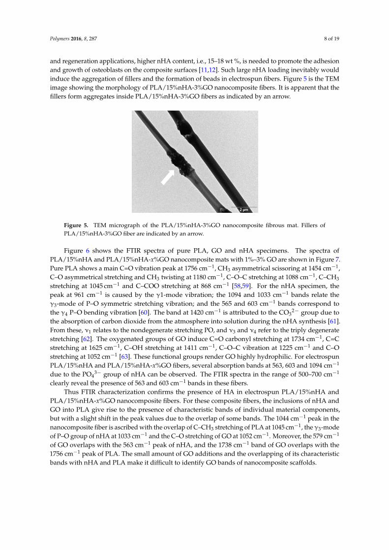
and regeneration applications, higher nHA content, i.e., 15–18 wt %, is needed to promote the adhesionand growth of osteoblasts on the composite surfaces [11,12]. Such large nHA loading inevitably wouldinduce the aggregation of fillers and the formation of beads in electrospun fibers. Figure 5 is the TEMimage showing the morphology of PLA/15%nHA-3%GO nanocomposite fibers. It is apparent that thefillers form aggregates inside PLA/15%nHA-3%GO fibers as indicated by an arrow.
Polymers 2016, 8, 287 8 of 18
promote the adhesion and growth of osteoblasts on the composite surfaces [11,12]. Such large nHA loading inevitably would induce the aggregation of fillers and the formation of beads in electrospun fibers. Figure 5 is the TEM image showing the morphology of PLA/15%nHA-3%GO nanocomposite fibers. It is apparent that the fillers form aggregates inside PLA/15%nHA-3%GO fibers as indicated by an arrow.
Figure 5. TEM micrograph of the PLA/15%nHA-3%GO nanocomposite fibrous mat. Fillers of PLA/15%nHA-3%GO fiber are indicated by an arrow.
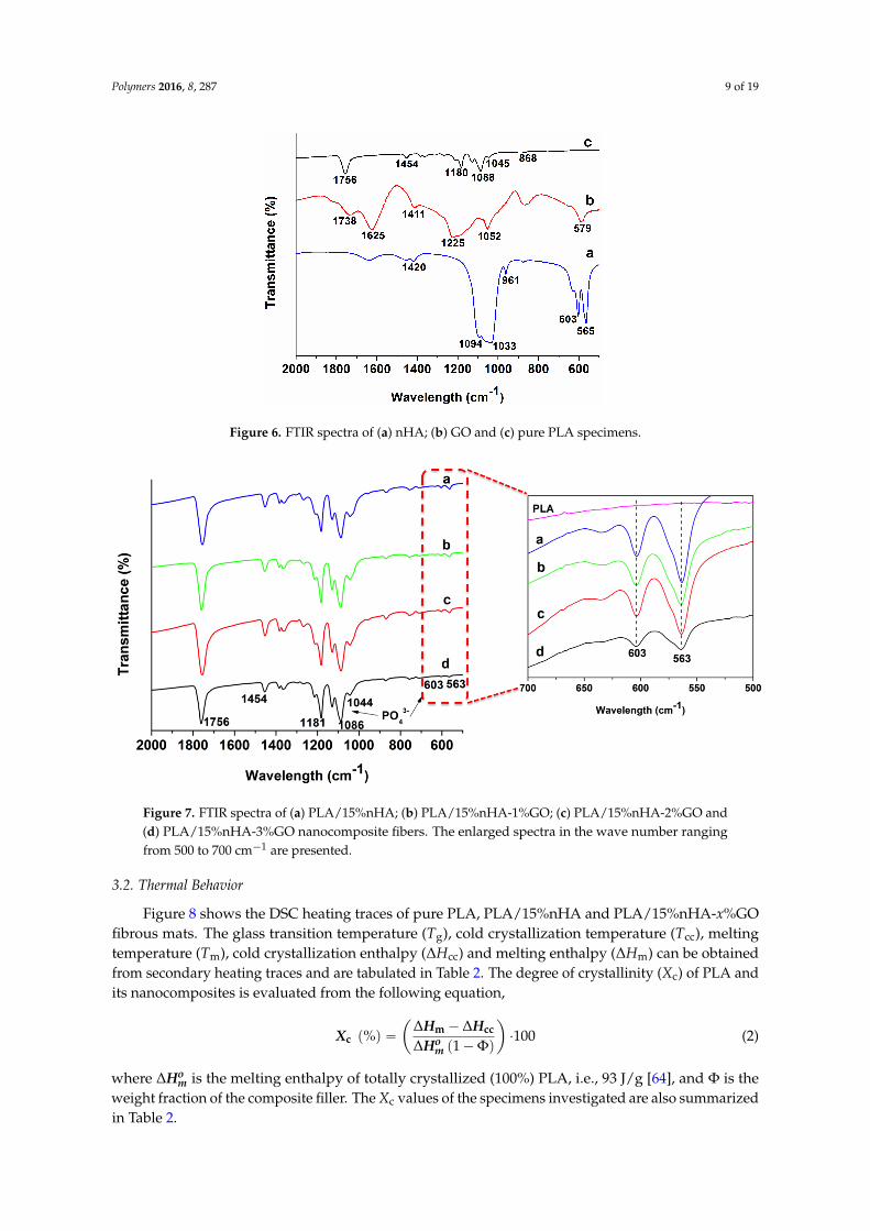
Figure 6 shows the FTIR spectra of pure PLA, GO and nHA specimens. The spectra of PLA/15%nHA and PLA/15%nHA-x%GO nanocomposite mats with 1%–3% GO are shown in Figure 7. Pure PLA shows a main C=O vibration peak at 1756 cm−1, CH3 asymmetrical scissoring at 1454 cm−1, C–O asymmetrical stretching and CH3 twisting at 1180 cm−1, C–O–C stretching at 1088 cm−1, C–CH3 stretching at 1045 cm−1 and C–COO stretching at 868 cm−1 [58,59]. For the nHA specimen, the peak at 961 cm−1 is caused by the γ1-mode vibration; the 1094 and 1033 cm−1 bands relate the γ3-mode of P–O symmetric stretching vibration; and the 565 and 603 cm−1 bands correspond to the γ4 P–O bending vibration [60]. The band at 1420 cm−1 is attributed to the CO32− group due to the absorption of carbon dioxide from the atmosphere into solution during the nHA synthesis [61]. From these, ν1 relates to the nondegenerate stretching PO, and ν3 and ν4 refer to the triply degenerate stretching [62]. The oxygenated groups of GO induce C=O carbonyl stretching at 1734 cm−1, C=C stretching at 1625 cm−1, C–OH stretching at 1411 cm−1, C–O–C vibration at 1225 cm−1 and C–O stretching at 1052 cm−1 [63]. These functional groups render GO highly hydrophilic. For electrospun PLA/15%nHA and PLA/15%nHA-x%GO fibers, several absorption bands at 563, 603 and 1094 cm−1 due to the PO43− group of nHA can be observed. The FTIR spectra in the range of 500–700 cm−1 clearly reveal the presence of 563 and 603 cm−1 bands in these fibers.
Thus FTIR characterization confirms the presence of HA in electrospun PLA/15%nHA and PLA/15%nHA-x%GO nanocomposite fibers. For these composite fibers, the inclusions of nHA and GO into PLA give rise to the presence of characteristic bands of individual material components, but with a slight shift in the peak values due to the overlap of some bands. The 1044 cm−1 peak in the nanocomposite fiber is ascribed with the overlap of C–CH3 stretching of PLA at 1045 cm−1, the γ3-mode of P–O group of nHA at 1033 cm−1 and the C–O stretching of GO at 1052 cm−1. Moreover, the 579 cm−1 of GO overlaps with the 563 cm−1 peak of nHA, and the 1738 cm−1 band of GO overlaps with the 1756 cm−1 peak of PLA. The small amount of GO additions and the overlapping of its characteristic bands with nHA and PLA make it difficult to identify GO bands of nanocomposite scaffolds.
Figure 5. TEM micrograph of the PLA/15%nHA-3%GO nanocomposite fibrous mat. Fillers ofPLA/15%nHA-3%GO fiber are indicated by an arrow.
Figure 6 shows the FTIR spectra of pure PLA, GO and nHA specimens. The spectra ofPLA/15%nHA and PLA/15%nHA-x%GO nanocomposite mats with 1%–3% GO are shown in Figure 7.Pure PLA shows a main C=O vibration peak at 1756 cm´1, CH3 asymmetrical scissoring at 1454 cm´1,C–O asymmetrical stretching and CH3 twisting at 1180 cm´1, C–O–C stretching at 1088 cm´1, C–CH3
stretching at 1045 cm´1 and C–COO stretching at 868 cm´1 [58,59]. For the nHA specimen, thepeak at 961 cm´1 is caused by the γ1-mode vibration; the 1094 and 1033 cm´1 bands relate theγ3-mode of P–O symmetric stretching vibration; and the 565 and 603 cm´1 bands correspond tothe γ4 P–O bending vibration [60]. The band at 1420 cm´1 is attributed to the CO3
2´ group due tothe absorption of carbon dioxide from the atmosphere into solution during the nHA synthesis [61].From these, ν1 relates to the nondegenerate stretching PO, and ν3 and ν4 refer to the triply degeneratestretching [62]. The oxygenated groups of GO induce C=O carbonyl stretching at 1734 cm´1, C=Cstretching at 1625 cm´1, C–OH stretching at 1411 cm´1, C–O–C vibration at 1225 cm´1 and C–Ostretching at 1052 cm´1 [63]. These functional groups render GO highly hydrophilic. For electrospunPLA/15%nHA and PLA/15%nHA-x%GO fibers, several absorption bands at 563, 603 and 1094 cm´1
due to the PO43´ group of nHA can be observed. The FTIR spectra in the range of 500–700 cm´1
clearly reveal the presence of 563 and 603 cm´1 bands in these fibers.Thus FTIR characterization confirms the presence of HA in electrospun PLA/15%nHA and
PLA/15%nHA-x%GO nanocomposite fibers. For these composite fibers, the inclusions of nHA andGO into PLA give rise to the presence of characteristic bands of individual material components,but with a slight shift in the peak values due to the overlap of some bands. The 1044 cm´1 peak in thenanocomposite fiber is ascribed with the overlap of C–CH3 stretching of PLA at 1045 cm´1, the γ3-modeof P–O group of nHA at 1033 cm´1 and the C–O stretching of GO at 1052 cm´1. Moreover, the 579 cm´1
of GO overlaps with the 563 cm´1 peak of nHA, and the 1738 cm´1 band of GO overlaps with the1756 cm´1 peak of PLA. The small amount of GO additions and the overlapping of its characteristicbands with nHA and PLA make it difficult to identify GO bands of nanocomposite scaffolds.
Polymers 2016, 8, 287 9 of 19Polymers 2016, 8, 287 9 of 18
Figure 6. FTIR spectra of (a) nHA, (b) GO and (c) pure PLA specimens.
Figure 7. FTIR spectra of (a) PLA/15%nHA, (b) PLA/15%nHA-1%GO, (c) PLA/15%nHA-2%GO and (d) PLA/15%nHA-3%GO nanocomposite fibers. The enlarged spectra in the wave number ranging from 500 to 700 cm−1 are presented.
3.2. Thermal Behavior
Figure 8 shows the DSC heating traces of pure PLA, PLA/15%nHA and PLA/15%nHA-x%GO fibrous mats. The glass transition temperature (Tg), cold crystallization temperature (Tcc), melting temperature (Tm), cold crystallization enthalpy (ΔHcc) and melting enthalpy (ΔHm) can be obtained from secondary heating traces and are tabulated in Table 2. The degree of crystallinity (Χc) of PLA and its nanocomposites is evaluated from the following equation, % = ∆ − ∆∆ − ∅ ∙ (2)
where ∆ is the melting enthalpy of totally crystallized (100%) PLA, i.e., 93 J/g [64], and Φ is the weight fraction of the composite filler. The Χc values of the specimens investigated are also summarized in Table 2.
Figure 6. FTIR spectra of (a) nHA; (b) GO and (c) pure PLA specimens.
Polymers 2016, 8, 287 9 of 18
Figure 6. FTIR spectra of (a) nHA, (b) GO and (c) pure PLA specimens.
Figure 7. FTIR spectra of (a) PLA/15%nHA, (b) PLA/15%nHA-1%GO, (c) PLA/15%nHA-2%GO and (d) PLA/15%nHA-3%GO nanocomposite fibers. The enlarged spectra in the wave number ranging from 500 to 700 cm−1 are presented.
3.2. Thermal Behavior
Figure 8 shows the DSC heating traces of pure PLA, PLA/15%nHA and PLA/15%nHA-x%GO fibrous mats. The glass transition temperature (Tg), cold crystallization temperature (Tcc), melting temperature (Tm), cold crystallization enthalpy (ΔHcc) and melting enthalpy (ΔHm) can be obtained from secondary heating traces and are tabulated in Table 2. The degree of crystallinity (Χc) of PLA and its nanocomposites is evaluated from the following equation, % = ∆ − ∆∆ − ∅ ∙ (2)
where ∆ is the melting enthalpy of totally crystallized (100%) PLA, i.e., 93 J/g [64], and Φ is the weight fraction of the composite filler. The Χc values of the specimens investigated are also summarized in Table 2.
Figure 7. FTIR spectra of (a) PLA/15%nHA; (b) PLA/15%nHA-1%GO; (c) PLA/15%nHA-2%GO and(d) PLA/15%nHA-3%GO nanocomposite fibers. The enlarged spectra in the wave number rangingfrom 500 to 700 cm´1 are presented.
3.2. Thermal Behavior
Figure 8 shows the DSC heating traces of pure PLA, PLA/15%nHA and PLA/15%nHA-x%GOfibrous mats. The glass transition temperature (Tg), cold crystallization temperature (Tcc), meltingtemperature (Tm), cold crystallization enthalpy (∆Hcc) and melting enthalpy (∆Hm) can be obtainedfrom secondary heating traces and are tabulated in Table 2. The degree of crystallinity (Xc) of PLA andits nanocomposites is evaluated from the following equation,
Xc p%q “ˆ
∆Hm ´ ∆Hcc
∆Hom p1´Φq
˙
¨100 (2)
where ∆Hom is the melting enthalpy of totally crystallized (100%) PLA, i.e., 93 J/g [64], and Φ is the
weight fraction of the composite filler. The Xc values of the specimens investigated are also summarizedin Table 2.
Polymers 2016, 8, 287 10 of 19Polymers 2016, 8, 287 10 of 18
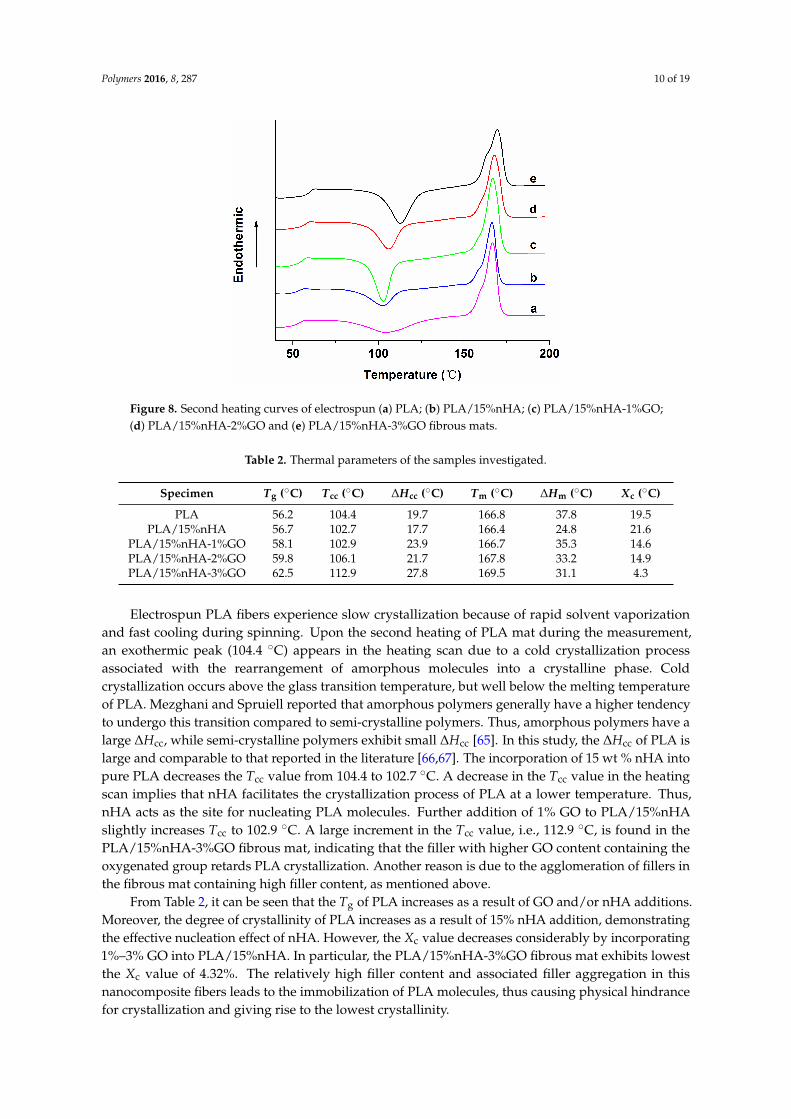
Figure 8. Second heating curves of electrospun (a) PLA, (b) PLA/15%nHA, (c) PLA/15%nHA-1%GO, (d) PLA/15%nHA-2%GO and (e) PLA/15%nHA-3%GO fibrous mats.
Table 2. Thermal parameters of the samples investigated.
Specimen Tg (°C) Tcc (°C) ΔHcc (°C) Tm (°C) ΔHm (°C) Xc (°C)
PLA 56.2 104.4 19.7 166.8 37.8 19.5 PLA/15%nHA 56.7 102.7 17.7 166.4 24.8 21.6
PLA/15%nHA-1%GO 58.1 102.9 23.9 166.7 35.3 14.6 PLA/15%nHA-2%GO 59.8 106.1 21.7 167.8 33.2 14.9 PLA/15%nHA-3%GO 62.5 112.9 27.8 169.5 31.1 4.3
Electrospun PLA fibers experience slow crystallization because of rapid solvent vaporization and fast cooling during spinning. Upon the second heating of PLA mat during the measurement, an exothermic peak (104.4 °C) appears in the heating scan due to a cold crystallization process associated with the rearrangement of amorphous molecules into a crystalline phase. Cold crystallization occurs above the glass transition temperature, but well below the melting temperature of PLA. Mezghani and Spruiell reported that amorphous polymers generally have a higher tendency to undergo this transition compared to semi-crystalline polymers. Thus, amorphous polymers have a large ΔHcc, while semi-crystalline polymers exhibit small ΔHcc [65]. In this study, the ΔHcc of PLA is large and comparable to that reported in the literature [66,67]. The incorporation of 15 wt % nHA into pure PLA decreases the Tcc value from 104.4 to 102.7 °C. A decrease in the Tcc value in the heating scan implies that nHA facilitates the crystallization process of PLA at a lower temperature. Thus, nHA acts as the site for nucleating PLA molecules. Further addition of 1% GO to PLA/15%nHA slightly increases Tcc to 102.9 °C. A large increment in the Tcc value, i.e., 112.9 °C, is found in the PLA/15%nHA-3%GO fibrous mat, indicating that the filler with higher GO content containing the oxygenated group retards PLA crystallization. Another reason is due to the agglomeration of fillers in the fibrous mat containing high filler content, as mentioned above.
From Table 2, it can be seen that the Tg of PLA increases as a result of GO and/or nHA additions. Moreover, the degree of crystallinity of PLA increases as a result of 15% nHA addition, demonstrating the effective nucleation effect of nHA. However, the Xc value decreases considerably by incorporating 1%–3% GO into PLA/15%nHA. In particular, the PLA/15%nHA-3%GO fibrous mat exhibits lowest the Xc value of 4.32%. The relatively high filler content and associated filler aggregation in this nanocomposite fibers leads to the immobilization of PLA molecules, thus causing physical hindrance for crystallization and giving rise to the lowest crystallinity.
Figure 8. Second heating curves of electrospun (a) PLA; (b) PLA/15%nHA; (c) PLA/15%nHA-1%GO;(d) PLA/15%nHA-2%GO and (e) PLA/15%nHA-3%GO fibrous mats.
Table 2. Thermal parameters of the samples investigated.
Specimen Tg (˝C) Tcc (˝C) ∆Hcc (˝C) Tm (˝C) ∆Hm (˝C) Xc (˝C)
PLA 56.2 104.4 19.7 166.8 37.8 19.5PLA/15%nHA 56.7 102.7 17.7 166.4 24.8 21.6
PLA/15%nHA-1%GO 58.1 102.9 23.9 166.7 35.3 14.6PLA/15%nHA-2%GO 59.8 106.1 21.7 167.8 33.2 14.9PLA/15%nHA-3%GO 62.5 112.9 27.8 169.5 31.1 4.3
Electrospun PLA fibers experience slow crystallization because of rapid solvent vaporizationand fast cooling during spinning. Upon the second heating of PLA mat during the measurement,an exothermic peak (104.4 ˝C) appears in the heating scan due to a cold crystallization processassociated with the rearrangement of amorphous molecules into a crystalline phase. Coldcrystallization occurs above the glass transition temperature, but well below the melting temperatureof PLA. Mezghani and Spruiell reported that amorphous polymers generally have a higher tendencyto undergo this transition compared to semi-crystalline polymers. Thus, amorphous polymers have alarge ∆Hcc, while semi-crystalline polymers exhibit small ∆Hcc [65]. In this study, the ∆Hcc of PLA islarge and comparable to that reported in the literature [66,67]. The incorporation of 15 wt % nHA intopure PLA decreases the Tcc value from 104.4 to 102.7 ˝C. A decrease in the Tcc value in the heatingscan implies that nHA facilitates the crystallization process of PLA at a lower temperature. Thus,nHA acts as the site for nucleating PLA molecules. Further addition of 1% GO to PLA/15%nHAslightly increases Tcc to 102.9 ˝C. A large increment in the Tcc value, i.e., 112.9 ˝C, is found in thePLA/15%nHA-3%GO fibrous mat, indicating that the filler with higher GO content containing theoxygenated group retards PLA crystallization. Another reason is due to the agglomeration of fillers inthe fibrous mat containing high filler content, as mentioned above.
From Table 2, it can be seen that the Tg of PLA increases as a result of GO and/or nHA additions.Moreover, the degree of crystallinity of PLA increases as a result of 15% nHA addition, demonstratingthe effective nucleation effect of nHA. However, the Xc value decreases considerably by incorporating1%–3% GO into PLA/15%nHA. In particular, the PLA/15%nHA-3%GO fibrous mat exhibits lowestthe Xc value of 4.32%. The relatively high filler content and associated filler aggregation in thisnanocomposite fibers leads to the immobilization of PLA molecules, thus causing physical hindrancefor crystallization and giving rise to the lowest crystallinity.
Polymers 2016, 8, 287 11 of 19
3.3. Tensile Behavior
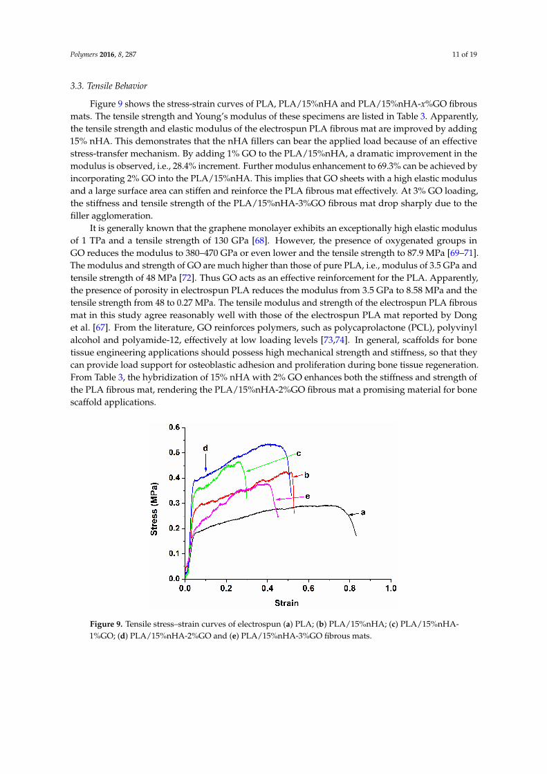
Figure 9 shows the stress-strain curves of PLA, PLA/15%nHA and PLA/15%nHA-x%GO fibrousmats. The tensile strength and Young’s modulus of these specimens are listed in Table 3. Apparently,the tensile strength and elastic modulus of the electrospun PLA fibrous mat are improved by adding15% nHA. This demonstrates that the nHA fillers can bear the applied load because of an effectivestress-transfer mechanism. By adding 1% GO to the PLA/15%nHA, a dramatic improvement in themodulus is observed, i.e., 28.4% increment. Further modulus enhancement to 69.3% can be achieved byincorporating 2% GO into the PLA/15%nHA. This implies that GO sheets with a high elastic modulusand a large surface area can stiffen and reinforce the PLA fibrous mat effectively. At 3% GO loading,the stiffness and tensile strength of the PLA/15%nHA-3%GO fibrous mat drop sharply due to thefiller agglomeration.
It is generally known that the graphene monolayer exhibits an exceptionally high elastic modulusof 1 TPa and a tensile strength of 130 GPa [68]. However, the presence of oxygenated groups inGO reduces the modulus to 380–470 GPa or even lower and the tensile strength to 87.9 MPa [69–71].The modulus and strength of GO are much higher than those of pure PLA, i.e., modulus of 3.5 GPa andtensile strength of 48 MPa [72]. Thus GO acts as an effective reinforcement for the PLA. Apparently,the presence of porosity in electrospun PLA reduces the modulus from 3.5 GPa to 8.58 MPa and thetensile strength from 48 to 0.27 MPa. The tensile modulus and strength of the electrospun PLA fibrousmat in this study agree reasonably well with those of the electrospun PLA mat reported by Donget al. [67]. From the literature, GO reinforces polymers, such as polycaprolactone (PCL), polyvinylalcohol and polyamide-12, effectively at low loading levels [73,74]. In general, scaffolds for bonetissue engineering applications should possess high mechanical strength and stiffness, so that theycan provide load support for osteoblastic adhesion and proliferation during bone tissue regeneration.From Table 3, the hybridization of 15% nHA with 2% GO enhances both the stiffness and strength ofthe PLA fibrous mat, rendering the PLA/15%nHA-2%GO fibrous mat a promising material for bonescaffold applications.
Polymers 2016, 8, 287 11 of 18
3.3. Tensile Behavior
Figure 9 shows the stress-strain curves of PLA, PLA/15%nHA and PLA/15%nHA-x%GO fibrous mats. The tensile strength and Young’s modulus of these specimens are listed in Table 3. Apparently, the tensile strength and elastic modulus of the electrospun PLA fibrous mat are improved by adding 15% nHA. This demonstrates that the nHA fillers can bear the applied load because of an effective stress-transfer mechanism. By adding 1% GO to the PLA/15%nHA, a dramatic improvement in the modulus is observed, i.e., 28.4% increment. Further modulus enhancement to 69.3% can be achieved by incorporating 2% GO into the PLA/15%nHA. This implies that GO sheets with a high elastic modulus and a large surface area can stiffen and reinforce the PLA fibrous mat effectively. At 3% GO loading, the stiffness and tensile strength of the PLA/15%nHA-3%GO fibrous mat drop sharply due to the filler agglomeration.
It is generally known that the graphene monolayer exhibits an exceptionally high elastic modulus of 1 TPa and a tensile strength of 130 GPa [68]. However, the presence of oxygenated groups in GO reduces the modulus to 380–470 GPa or even lower and the tensile strength to 87.9 MPa [69–71]. The modulus and strength of GO are much higher than those of pure PLA, i.e., modulus of 3.5 GPa and tensile strength of 48 MPa [72]. Thus GO acts as an effective reinforcement for the PLA. Apparently, the presence of porosity in electrospun PLA reduces the modulus from 3.5 GPa to 8.58 MPa and the tensile strength from 48 to 0.27 MPa. The tensile modulus and strength of the electrospun PLA fibrous mat in this study agree reasonably well with those of the electrospun PLA mat reported by Dong et al. [67]. From the literature, GO reinforces polymers, such as polycaprolactone (PCL), polyvinyl alcohol and polyamide-12, effectively at low loading levels [73,74]. In general, scaffolds for bone tissue engineering applications should possess high mechanical strength and stiffness, so that they can provide load support for osteoblastic adhesion and proliferation during bone tissue regeneration. From Table 3, the hybridization of 15% nHA with 2% GO enhances both the stiffness and strength of the PLA fibrous mat, rendering the PLA/15%nHA-2%GO fibrous mat a promising material for bone scaffold applications.
Figure 9. Tensile stress–strain curves of electrospun (a) PLA; (b) PLA/15%nHA; (c) PLA/15%nHA-1%GO; (d) PLA/15%nHA-2%GO and (e) PLA/15%nHA-3%GO fibrous mats.
Figure 9. Tensile stress–strain curves of electrospun (a) PLA; (b) PLA/15%nHA; (c) PLA/15%nHA-1%GO; (d) PLA/15%nHA-2%GO and (e) PLA/15%nHA-3%GO fibrous mats.
Polymers 2016, 8, 287 12 of 19
Table 3. Tensile properties of electrospun PLA and PLA-based nanocomposite fibrous mats.
Specimen Elastic modulus (MPa) Tensile stress (MPa)
PLA 8.58 ˘ 0.53 0.27 ˘ 0.04PLA/15%nHA 9.88 ˘ 0.31 0.41 ˘ 0.05
PLA/15%nHA-1%GO 12.69 ˘ 0.86 0.47 ˘ 0.03PLA/15%nHA-2%GO 16.73 ˘ 0.21 0.57 ˘ 0.04PLA/15%nHA-3%GO 8.10 ˘ 0.50 0.38 ˘ 0.03
3.4. Water Absorption
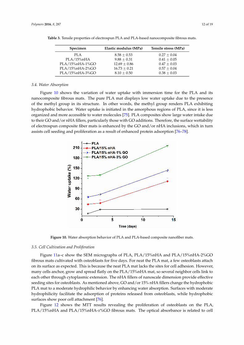
Figure 10 shows the variation of water uptake with immersion time for the PLA and itsnanocomposite fibrous mats. The pure PLA mat displays low water uptake due to the presenceof the methyl group in its structure. In other words, the methyl group renders PLA exhibitinghydrophobic behavior. Water uptake is initiated in the amorphous regions of PLA, since it is lessorganized and more accessible to water molecules [75]. PLA composites show large water intake dueto their GO and/or nHA fillers, particularly those with GO additions. Therefore, the surface wettabilityof electrospun composite fiber mats is enhanced by the GO and/or nHA inclusions, which in turnassists cell seeding and proliferation as a result of enhanced protein adsorption [76–78].
Polymers 2016, 8, 287 12 of 18
Table 3. Tensile properties of electrospun PLA and PLA-based nanocomposite fibrous mats.
Specimen Elastic modulus (MPa) Tensile stress (MPa)
PLA 8.58 ± 0.53 0.27 ± 0.04 PLA/15%nHA 9.88 ± 0.31 0.41 ± 0.05
PLA/15%nHA-1%GO 12.69 ± 0.86 0.47 ± 0.03 PLA/15%nHA-2%GO 16.73 ± 0.21 0.57 ± 0.04 PLA/15%nHA-3%GO 8.10 ± 0.50 0.38 ± 0.03
3.4. Water Absorption
Figure 10 shows the variation of water uptake with immersion time for the PLA and its nanocomposite fibrous mats. The pure PLA mat displays low water uptake due to the presence of the methyl group in its structure. In other words, the methyl group renders PLA exhibiting hydrophobic behavior. Water uptake is initiated in the amorphous regions of PLA, since it is less organized and more accessible to water molecules [75]. PLA composites show large water intake due to their GO and/or nHA fillers, particularly those with GO additions. Therefore, the surface wettability of electrospun composite fiber mats is enhanced by the GO and/or nHA inclusions, which in turn assists cell seeding and proliferation as a result of enhanced protein adsorption [76–78].
Figure 10. Water absorption behavior of PLA and PLA-based composite nanofiber mats.
3.5. Cell Cultivation and Proliferation
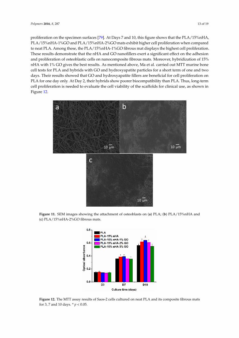
Figure 11a–c show the SEM micrographs of PLA, PLA/15%nHA and PLA/15%nHA-2%GO fibrous mats cultivated with osteoblasts for five days. For neat the PLA mat, a few osteoblasts attach on its surface as expected. This is because the neat PLA mat lacks the sites for cell adhesion. However, many cells anchor, grow and spread flatly on the PLA/15%nHA mat, so several neighbor cells link to each other through cytoplasmic extension. The nHA fillers of nanoscale dimension provide effective seeding sites for osteoblasts. As mentioned above, GO and/or 15% nHA fillers change the hydrophobic PLA mat to a moderate hydrophilic behavior by enhancing water absorption. Surfaces with moderate hydrophilicity facilitate the adsorption of proteins released from osteoblasts, while hydrophobic surfaces show poor cell attachment [76].
Figure 12 shows the MTT results revealing the proliferation of osteoblasts on the PLA, PLA/15%nHA and PLA/15%nHA-x%GO fibrous mats. The optical absorbance is related to cell
Figure 10. Water absorption behavior of PLA and PLA-based composite nanofiber mats.
3.5. Cell Cultivation and Proliferation
Figure 11a–c show the SEM micrographs of PLA, PLA/15%nHA and PLA/15%nHA-2%GOfibrous mats cultivated with osteoblasts for five days. For neat the PLA mat, a few osteoblasts attachon its surface as expected. This is because the neat PLA mat lacks the sites for cell adhesion. However,many cells anchor, grow and spread flatly on the PLA/15%nHA mat, so several neighbor cells link toeach other through cytoplasmic extension. The nHA fillers of nanoscale dimension provide effectiveseeding sites for osteoblasts. As mentioned above, GO and/or 15% nHA fillers change the hydrophobicPLA mat to a moderate hydrophilic behavior by enhancing water absorption. Surfaces with moderatehydrophilicity facilitate the adsorption of proteins released from osteoblasts, while hydrophobicsurfaces show poor cell attachment [76].
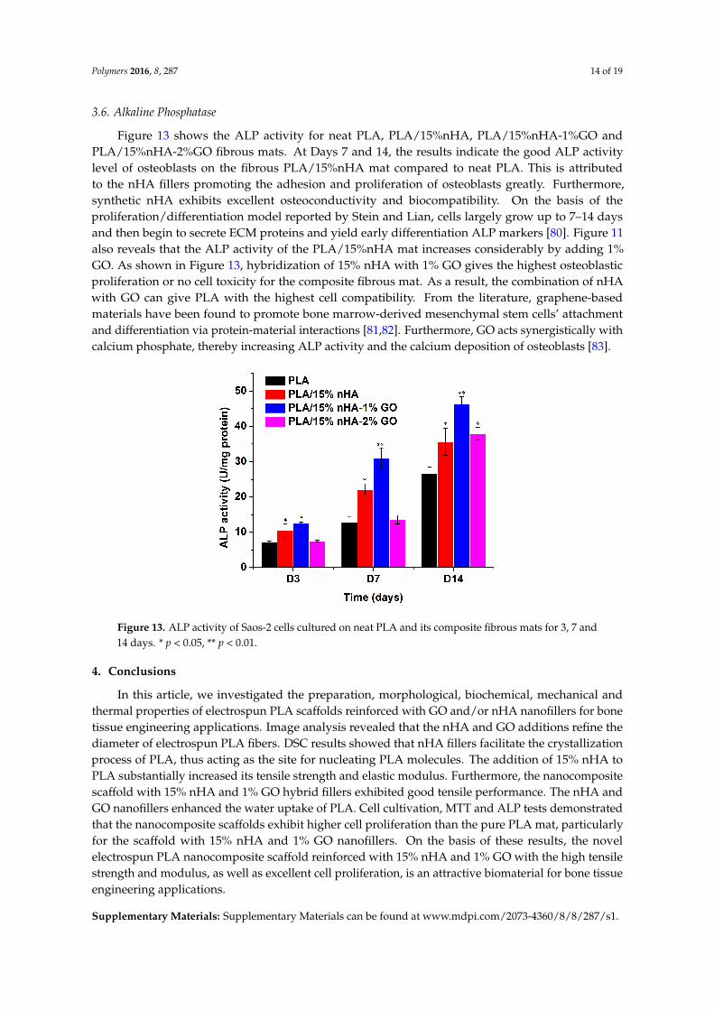
Figure 12 shows the MTT results revealing the proliferation of osteoblasts on the PLA,PLA/15%nHA and PLA/15%nHA-x%GO fibrous mats. The optical absorbance is related to cell
Polymers 2016, 8, 287 13 of 19
proliferation on the specimen surfaces [79]. At Days 7 and 10, this figure shows that the PLA/15%nHA,PLA/15%nHA-1%GO and PLA/15%nHA-2%GO mats exhibit higher cell proliferation when comparedto neat PLA. Among these, the PLA/15%nHA-1%GO fibrous mat displays the highest cell proliferation.These results demonstrate that the nHA and GO nanofillers exert a significant effect on the adhesionand proliferation of osteoblastic cells on nanocomposite fibrous mats. Moreover, hybridization of 15%nHA with 1% GO gives the best results. As mentioned above, Ma et al. carried out MTT murine bonecell tests for PLA and hybrids with GO and hydroxyapatite particles for a short term of one and twodays. Their results showed that GO and hydroxyapatite fillers are beneficial for cell proliferation onPLA for one day only. At Day 2, their hybrids show poorer biocompatibility than PLA. Thus, long-termcell proliferation is needed to evaluate the cell viability of the scaffolds for clinical use, as shown inFigure 12.
Polymers 2016, 8, 287 13 of 18
proliferation on the specimen surfaces [79]. At Days 7 and 10, this figure shows that the PLA/15%nHA, PLA/15%nHA-1%GO and PLA/15%nHA-2%GO mats exhibit higher cell proliferation when compared to neat PLA. Among these, the PLA/15%nHA-1%GO fibrous mat displays the highest cell proliferation. These results demonstrate that the nHA and GO nanofillers exert a significant effect on the adhesion and proliferation of osteoblastic cells on nanocomposite fibrous mats. Moreover, hybridization of 15% nHA with 1% GO gives the best results. As mentioned above, Ma et al. carried out MTT murine bone cell tests for PLA and hybrids with GO and hydroxyapatite particles for a short term of one and two days. Their results showed that GO and hydroxyapatite fillers are beneficial for cell proliferation on PLA for one day only. At Day 2, their hybrids show poorer biocompatibility than PLA. Thus, long-term cell proliferation is needed to evaluate the cell viability of the scaffolds for clinical use, as shown in Figure 12.
Figure 11. SEM images showing the attachment of osteoblasts on (a) PLA; (b) PLA/15%nHA and (c) PLA/15%nHA-2%GO fibrous mats.
Figure 12. The MTT assay results of Saos-2 cells cultured on neat PLA and its composite fibrous mats for 3, 7 and 10 days. * p < 0.05.
Figure 11. SEM images showing the attachment of osteoblasts on (a) PLA; (b) PLA/15%nHA and(c) PLA/15%nHA-2%GO fibrous mats.
Polymers 2016, 8, 287 13 of 18
proliferation on the specimen surfaces [79]. At Days 7 and 10, this figure shows that the PLA/15%nHA, PLA/15%nHA-1%GO and PLA/15%nHA-2%GO mats exhibit higher cell proliferation when compared to neat PLA. Among these, the PLA/15%nHA-1%GO fibrous mat displays the highest cell proliferation. These results demonstrate that the nHA and GO nanofillers exert a significant effect on the adhesion and proliferation of osteoblastic cells on nanocomposite fibrous mats. Moreover, hybridization of 15% nHA with 1% GO gives the best results. As mentioned above, Ma et al. carried out MTT murine bone cell tests for PLA and hybrids with GO and hydroxyapatite particles for a short term of one and two days. Their results showed that GO and hydroxyapatite fillers are beneficial for cell proliferation on PLA for one day only. At Day 2, their hybrids show poorer biocompatibility than PLA. Thus, long-term cell proliferation is needed to evaluate the cell viability of the scaffolds for clinical use, as shown in Figure 12.
Figure 11. SEM images showing the attachment of osteoblasts on (a) PLA; (b) PLA/15%nHA and (c) PLA/15%nHA-2%GO fibrous mats.
Figure 12. The MTT assay results of Saos-2 cells cultured on neat PLA and its composite fibrous mats for 3, 7 and 10 days. * p < 0.05.
Figure 12. The MTT assay results of Saos-2 cells cultured on neat PLA and its composite fibrous matsfor 3, 7 and 10 days. * p < 0.05.
Polymers 2016, 8, 287 14 of 19
3.6. Alkaline Phosphatase
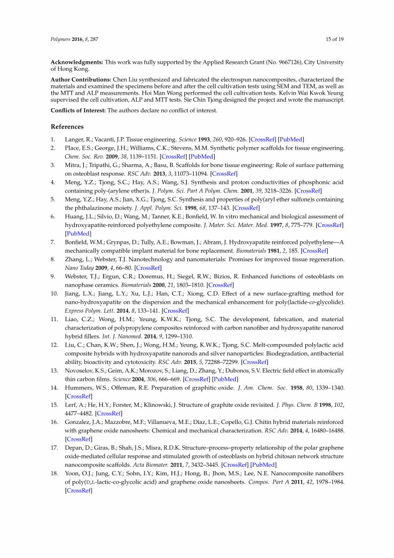
Figure 13 shows the ALP activity for neat PLA, PLA/15%nHA, PLA/15%nHA-1%GO andPLA/15%nHA-2%GO fibrous mats. At Days 7 and 14, the results indicate the good ALP activitylevel of osteoblasts on the fibrous PLA/15%nHA mat compared to neat PLA. This is attributedto the nHA fillers promoting the adhesion and proliferation of osteoblasts greatly. Furthermore,synthetic nHA exhibits excellent osteoconductivity and biocompatibility. On the basis of theproliferation/differentiation model reported by Stein and Lian, cells largely grow up to 7–14 daysand then begin to secrete ECM proteins and yield early differentiation ALP markers [80]. Figure 11also reveals that the ALP activity of the PLA/15%nHA mat increases considerably by adding 1%GO. As shown in Figure 13, hybridization of 15% nHA with 1% GO gives the highest osteoblasticproliferation or no cell toxicity for the composite fibrous mat. As a result, the combination of nHAwith GO can give PLA with the highest cell compatibility. From the literature, graphene-basedmaterials have been found to promote bone marrow-derived mesenchymal stem cells’ attachmentand differentiation via protein-material interactions [81,82]. Furthermore, GO acts synergistically withcalcium phosphate, thereby increasing ALP activity and the calcium deposition of osteoblasts [83].
Polymers 2016, 8, 287 14 of 18
3.6. Alkaline Phosphatase
Figure 13 shows the ALP activity for neat PLA, PLA/15%nHA, PLA/15%nHA-1%GO and PLA/15%nHA-2%GO fibrous mats. At Days 7 and 14, the results indicate the good ALP activity level of osteoblasts on the fibrous PLA/15%nHA mat compared to neat PLA. This is attributed to the nHA fillers promoting the adhesion and proliferation of osteoblasts greatly. Furthermore, synthetic nHA exhibits excellent osteoconductivity and biocompatibility. On the basis of the proliferation/differentiation model reported by Stein and Lian, cells largely grow up to 7–14 days and then begin to secrete ECM proteins and yield early differentiation ALP markers [80]. Figure 11 also reveals that the ALP activity of the PLA/15%nHA mat increases considerably by adding 1% GO. As shown in Figure 13, hybridization of 15% nHA with 1% GO gives the highest osteoblastic proliferation or no cell toxicity for the composite fibrous mat. As a result, the combination of nHA with GO can give PLA with the highest cell compatibility. From the literature, graphene-based materials have been found to promote bone marrow-derived mesenchymal stem cells’ attachment and differentiation via protein-material interactions [81,82]. Furthermore, GO acts synergistically with calcium phosphate, thereby increasing ALP activity and the calcium deposition of osteoblasts [83].
Figure 13. ALP activity of Saos-2 cells cultured on neat PLA and its composite fibrous mats for 3, 7 and 14 days. * p < 0.05, ** p < 0.01.
4. Conclusions
In this article, we investigated the preparation, morphological, biochemical, mechanical and thermal properties of electrospun PLA scaffolds reinforced with GO and/or nHA nanofillers for bone tissue engineering applications. Image analysis revealed that the nHA and GO additions refine the diameter of electrospun PLA fibers. DSC results showed that nHA fillers facilitate the crystallization process of PLA, thus acting as the site for nucleating PLA molecules. The addition of 15% nHA to PLA substantially increased its tensile strength and elastic modulus. Furthermore, the nanocomposite scaffold with 15% nHA and 1% GO hybrid fillers exhibited good tensile performance. The nHA and GO nanofillers enhanced the water uptake of PLA. Cell cultivation, MTT and ALP tests demonstrated that the nanocomposite scaffolds exhibit higher cell proliferation than the pure PLA mat, particularly for the scaffold with 15% nHA and 1% GO nanofillers. On the basis of these results, the novel electrospun PLA nanocomposite scaffold reinforced with 15% nHA and 1% GO with the high tensile strength and modulus, as well as excellent cell proliferation, is an attractive biomaterial for bone tissue engineering applications.
Supplementary Materials: Supplementary Materials can be found at www.mdpi.com/2073-4360/8/8/287/s1.
Figure 13. ALP activity of Saos-2 cells cultured on neat PLA and its composite fibrous mats for 3, 7 and14 days. * p < 0.05, ** p < 0.01.
4. Conclusions
In this article, we investigated the preparation, morphological, biochemical, mechanical andthermal properties of electrospun PLA scaffolds reinforced with GO and/or nHA nanofillers for bonetissue engineering applications. Image analysis revealed that the nHA and GO additions refine thediameter of electrospun PLA fibers. DSC results showed that nHA fillers facilitate the crystallizationprocess of PLA, thus acting as the site for nucleating PLA molecules. The addition of 15% nHA toPLA substantially increased its tensile strength and elastic modulus. Furthermore, the nanocompositescaffold with 15% nHA and 1% GO hybrid fillers exhibited good tensile performance. The nHA andGO nanofillers enhanced the water uptake of PLA. Cell cultivation, MTT and ALP tests demonstratedthat the nanocomposite scaffolds exhibit higher cell proliferation than the pure PLA mat, particularlyfor the scaffold with 15% nHA and 1% GO nanofillers. On the basis of these results, the novelelectrospun PLA nanocomposite scaffold reinforced with 15% nHA and 1% GO with the high tensilestrength and modulus, as well as excellent cell proliferation, is an attractive biomaterial for bone tissueengineering applications.
Supplementary Materials: Supplementary Materials can be found at www.mdpi.com/2073-4360/8/8/287/s1.
Polymers 2016, 8, 287 15 of 19
Acknowledgments: This work was fully supported by the Applied Research Grant (No. 9667126), City Universityof Hong Kong.
Author Contributions: Chen Liu synthesized and fabricated the electrospun nanocomposites, characterized thematerials and examined the specimens before and after the cell cultivation tests using SEM and TEM, as well asthe MTT and ALP measurements. Hoi Man Wong performed the cell cultivation tests. Kelvin Wai Kwok Yeungsupervised the cell cultivation, ALP and MTT tests. Sie Chin Tjong designed the project and wrote the manuscript.
Conflicts of Interest: The authors declare no conflict of interest.
References
1. Langer, R.; Vacanti, J.P. Tissue engineering. Science 1993, 260, 920–926. [CrossRef] [PubMed]2. Place, E.S.; George, J.H.; Williams, C.K.; Stevens, M.M. Synthetic polymer scaffolds for tissue engineering.
Chem. Soc. Rev. 2009, 38, 1139–1151. [CrossRef] [PubMed]3. Mitra, J.; Tripathi, G.; Sharma, A.; Basu, B. Scaffolds for bone tissue engineering: Role of surface patterning
on osteoblast response. RSC Adv. 2013, 3, 11073–11094. [CrossRef]4. Meng, Y.Z.; Tjong, S.C.; Hay, A.S.; Wang, S.J. Synthesis and proton conductivities of phosphonic acid
containing poly-(arylene ether)s. J. Polym. Sci. Part A Polym. Chem. 2001, 39, 3218–3226. [CrossRef]5. Meng, Y.Z.; Hay, A.S.; Jian, X.G.; Tjong, S.C. Synthesis and properties of poly(aryl ether sulfone)s containing
the phthalazinone moiety. J. Appl. Polym. Sci. 1998, 68, 137–143. [CrossRef]6. Huang, J.L.; Silvio, D.; Wang, M.; Tanner, K.E.; Bonfield, W. In vitro mechanical and biological assessment of
hydroxyapatite-reinforced polyethylene composite. J. Mater. Sci. Mater. Med. 1997, 8, 775–779. [CrossRef][PubMed]
7. Bonfield, W.M.; Grynpas, D.; Tully, A.E.; Bowman, J.; Abram, J. Hydroxyapatite reinforced polyethylene—Amechanically compatible implant material for bone replacement. Biomaterials 1981, 2, 185. [CrossRef]
8. Zhang, L.; Webster, T.J. Nanotechnology and nanomaterials: Promises for improved tissue regeneration.Nano Today 2009, 4, 66–80. [CrossRef]
9. Webster, T.J.; Ergun, C.R.; Doremus, H.; Siegel, R.W.; Bizios, R. Enhanced functions of osteoblasts onnanophase ceramics. Biomaterials 2000, 21, 1803–1810. [CrossRef]
10. Jiang, L.X.; Jiang, L.Y.; Xu, L.J.; Han, C.T.; Xiong, C.D. Effect of a new surface-grafting method fornano-hydroxyapatite on the dispersion and the mechanical enhancement for poly(lactide-co-glycolide).Express Polym. Lett. 2014, 8, 133–141. [CrossRef]
11. Liao, C.Z.; Wong, H.M.; Yeung, K.W.K.; Tjong, S.C. The development, fabrication, and materialcharacterization of polypropylene composites reinforced with carbon nanofiber and hydroxyapatite nanorodhybrid fillers. Int. J. Nanomed. 2014, 9, 1299–1310.
12. Liu, C.; Chan, K.W.; Shen, J.; Wong, H.M.; Yeung, K.W.K.; Tjong, S.C. Melt-compounded polylactic acidcomposite hybrids with hydroxyapatite nanorods and silver nanoparticles: Biodegradation, antibacterialability, bioactivity and cytotoxicity. RSC Adv. 2015, 5, 72288–72299. [CrossRef]
13. Novoselov, K.S.; Geim, A.K.; Morozov, S.; Liang, D.; Zhang, Y.; Dubonos, S.V. Electric field effect in atomicallythin carbon films. Science 2004, 306, 666–669. [CrossRef] [PubMed]
14. Hummers, W.S.; Offeman, R.E. Preparation of graphitic oxide. J. Am. Chem. Soc. 1958, 80, 1339–1340.[CrossRef]
15. Lerf, A.; He, H.Y.; Forster, M.; Klinowski, J. Structure of graphite oxide revisited. J. Phys. Chem. B 1998, 102,4477–4482. [CrossRef]
16. Gonzalez, J.A.; Mazzobre, M.F.; Villanueva, M.E.; Díaz, L.E.; Copello, G.J. Chitin hybrid materials reinforcedwith graphene oxide nanosheets: Chemical and mechanical characterization. RSC Adv. 2014, 4, 16480–16488.[CrossRef]
17. Depan, D.; Giras, B.; Shah, J.S.; Misra, R.D.K. Structure–process–property relationship of the polar grapheneoxide-mediated cellular response and stimulated growth of osteoblasts on hybrid chitosan network structurenanocomposite scaffolds. Acta Biomater. 2011, 7, 3432–3445. [CrossRef] [PubMed]
18. Yoon, O.J.; Jung, C.Y.; Sohn, I.Y.; Kim, H.J.; Hong, B.; Jhon, M.S.; Lee, N.E. Nanocomposite nanofibersof poly(D,L-lactic-co-glycolic acid) and graphene oxide nanosheets. Compos. Part A 2011, 42, 1978–1984.[CrossRef]
Polymers 2016, 8, 287 16 of 19
19. Chaudhuri, B.; Bhadra, D.; Moroni, L.; Pramanik, K. Myoblast differentiation of human mesenchymal stemcells on graphene oxide and electrospun graphene oxide-polymer composite fibrous meshes: Importance ofgraphene oxide conductivity and dielectric constant on their biocompatibility. Biofabrication 2015, 7, 015009.[CrossRef] [PubMed]
20. Pinto, A.M.; Moreira, S.I.; Goncalves, C.; Gama, F.M.; Mendes, A.M.; Magalhães, F.D. Biocompatibility ofpoly(lactic acid) with incorporated graphene-based materials. Colloids Surf. B Biointerfaces 2013, 104, 229–238.[CrossRef] [PubMed]
21. Reneker, D.H.; Yarin, A.L. Electrospinning jets and polymer nanofibers. Polymer 2008, 49, 2387–2425.[CrossRef]
22. Mokhena, T.C.; Jacobs, V.; Luyt, A.S. A review on electrospun bio-based polymers for water treatment.Express Polym. Lett. 2015, 9, 839–880. [CrossRef]
23. Kostakova1, E.; Seps, M.; Pokorny, P.; LUKas, D. Study of polycaprolactone wet electrospinning process.Express Polym. Lett. 2014, 8, 554–564. [CrossRef]
24. Koosha, M.; Mirzadeh, H.; Shokrgozar, M.A.; Farokhi, M. Nanoclay-reinforced electrospun chitosan/PVAnanocomposite nanofibers for biomedical applications. RSC Adv. 2015, 5, 10479–10487. [CrossRef]
25. Goonoo, N.; Bhaw-Luximon, A.; Jhurry, D. In vitro and in vivo cytocompatibility of electrospun nanofiberscaffolds for tissue engineering applications. RSC Adv. 2014, 4, 31618–31642. [CrossRef]
26. Asran, A.S.; Henning, S.; Michler, G.H. Polyvinyl alcohol–collagen–hydroxyapatite biocomposite nanofibrousscaffold: Mimicking the key features of natural bone at the nanoscale level. Polymer 2010, 51, 868–876.[CrossRef]
27. Zhou, Y.; Qi, P.; Zha, Z.; Liu, Q.; Li, Z. Fabrication and characterization of fibrous HAP/PVP/PEO compositesprepared by sol-electrospinning. RSC Adv. 2014, 4, 16731–16738. [CrossRef]
28. Thomas, V.; Dean, D.R.; Jose, M.V.; Mathew, B.; Chowdhury, S.; Vohra, Y.K. Nanostructured biocompositescaffolds based on collagen coelectrospun with nanohydroxyapatite. Biomacromolecules 2007, 8, 631–637.[CrossRef] [PubMed]
29. Neto, W.A.; Pereira, I.H.; Ayres, E.; de Paula, A.C.; Averous, L.A.; Góes, M.; Oréfice, R.L.; Elida, R.; Bretas, S.Influence of the microstructure and mechanical strength of nanofibers of biodegradable polymers withhydroxyapatite in stem cells growth. Electrospinning, characterization and cell viability. Polym. Degr. Stab.2012, 97, 2037–2051. [CrossRef]
30. Sonseca, A.; Peponi, L.; Sahuquillo, O.; Kenny, J.M.; Giménez, E. Electrospinning of biodegradablepolylactide/hydroxyapatite nanofibers: Study on the morphology, crystallinity structure and thermalstability. Polym. Degr. Stab. 2012, 97, 2052–2059. [CrossRef]
31. Polini, A.; Pisignano, D.; Parodi, M.; Quarto, R.; Scaglione, S. Osteoinduction of human mesenchymal stemcells by bioactive composite scaffolds without supplemental osteogenic growth factors. PLoS ONE 2011, 6,e26211. [CrossRef] [PubMed]
32. Wan, C.; Chen, B. Poly(ε-caprolactone)/graphene oxide biocomposites: mechanical properties and bioactivity.Biomed. Mater. 2011, 6, 055010. [CrossRef] [PubMed]
33. Ramakrishnan, S.; Dhakshnamoorthy, M.; Jelmy, E.J.; Vasanthakumari, R.; Kothurkar, N.K. Synthesis andcharacterization of graphene oxide–polyimide nanofiber composites. RSC Adv. 2014, 4, 9743–9749. [CrossRef]
34. Song, J.; Gao, H.; Zhu, G.; Cao, X.; Shi, X.; Wang, Y. The preparation and characterization ofpolycaprolactone/graphene oxide biocomposite nanofiber scaffolds and their application for directingcell behaviors. Carbon 2015, 95, 1039–1050. [CrossRef]
35. Panzavolta, S.; Bracci, B.; Gualandi, C.; Focarete, M.L.; Treossi, E.; Kouroupis-Agalou, K.; Rubini, K.; Bosia, F.;Brely, L.; Pugno, N.M.; et al. Structural reinforcement and failure analysis in composite nanofibers ofgraphene oxide and gelatin. Carbon 2014, 78, 566–577. [CrossRef]
36. Wang, M.; Li, Y.; Liu, Q.; Li, Q.; Cheng, Y.; Zheng, Y.; Xi, T.; Wei, S. In situ synthesis and biocompatibilityof nano hydroxyapatite on pristine and chitosan functionalized graphene oxide. J. Mater. Chem. B 2013, 1,475–484.
37. Rajesh, R.; Ravichandran, Y.D. Development of new graphene oxide incorporated tricomponent scaffoldswith polysaccharides and hydroxyapatite and study of their osteoconductivity on MG-63 cell line for bonetissue engineering. RSC Adv. 2015, 5, 41135–41143. [CrossRef]
Polymers 2016, 8, 287 17 of 19
38. Raquez, J.M.; Habibi, Y.; Murariu, M.; Dubois, P. Polylactide (PLA)-based nanocomposites. Prog. Polym. Sci.2013, 38, 1504–1542. [CrossRef]
39. Goswami, J.; Bhatnagar, N.; Mohanty, S.; Ghosh, A.K. Processing and characterization of poly(lactic acid)based bioactive composites for biomedical scaffold application. Express Polym. Lett. 2013, 7, 767–777.[CrossRef]
40. Kimble, L.D.; Bhattacharyya, D.; Fakirov, S. Biodegradable microfibrillar polymer-polymer composites frompoly(L-lactic acid)/poly(glycolic acid). Express Polym. Lett. 2015, 9, 300–307. [CrossRef]
41. Hamad, K.; Kaseem, M.; Yang, H.W.; Deri, F.; Ko, Y.G. Properties and medical applications of polylactic acid:A review. Express Polym. Lett. 2015, 9, 435–455. [CrossRef]
42. Wang, J.; Wang, L.; Zhou, Z.; Lai, H.; Xu, P.; Liao, L.; Wei, J. Biodegradable polymer membranes applied inguided bone/tissue regeneration: A review. Polymers 2016, 8, 115. [CrossRef]
43. Manavitehrani, I.; Fathi, A.; Badr, H.; Daly, S.; Shirazi, A.N.; Dehghani, F. Biomedical applications ofbiodegradable polyesters. Polymers 2016, 8, 20. [CrossRef]
44. Ma, P.; Jiang, L.; Ye, T.; Dong, W.; Chen, M. Poly melt free-radical grafting of maleic anhydride ontobiodegradable poly(lactic acid) by using styrene as a comonomer. Polymers 2014, 6, 1528–1543. [CrossRef]
45. Ma, H.; Su, W.; Tai, Z.; Sun, D.; Yan, X.; Liu, B.; Xu, Q. Preparation and cytocompatibility of polylacticacid/hydroxyapatite/graphene oxide nanocomposite fibrous membrane. Chin. Sci. Bull. 2012, 57, 3051–3058.[CrossRef]
46. Jaiswal, A.K.; Chhabra, H.; Kadam, S.S.; Londhe, K.; Soni, V.P.; Bellare, J.R. Hardystonite improvesbiocompatibility and strength of electrospun polycaprolactone nanofibers over hydroxyapatite: Acomparative study. Mater. Sci. Eng. C 2013, 33, 2926–2936. [CrossRef] [PubMed]
47. Rodríguez-Tobías, H.; Morales, G.; Ledezma, A.; Romero, J.; Grande, D. Novel antibacterial electrospunmats based on poly (D,L-lactide) nanofibers and zinc oxide nanoparticles. J. Mater. Sci. 2014, 49, 8373–8385.[CrossRef]
48. Kokubo, T.; Takadama, H. How useful is SBF in predicting in vivo bone bioactivity. Biomaterials 2006, 27,2907–2915. [CrossRef] [PubMed]
49. Singh, V.; Joung, D.; Zhai, L.; Das, S.; Khondaker, S.I.; Seal, S. Graphene based materials: Past, present andfuture. Prog. Mater. Sci. 2011, 56, 1178–1271. [CrossRef]
50. Ferrari, A.C. Raman spectroscopy of graphene and graphite: Disorder, electron–phonon coupling, dopingand nonadiabatic effects. Solid state commun. 2007, 143, 47–57. [CrossRef]
51. Perumbilavil, S.; Sankar, P.; Rose, T.P.; Philip, R. White light Z-scan measurements of ultrafast opticalnonlinearity in reduced graphene oxide nanosheets in the 400–700 nm region. Appl. Phys. Lett. 2015, 107,051104. [CrossRef]
52. Xu, X.; Chen, X.; Liu, A.; Hong, Z.; Jing, X. Electrospun poly(L-lactide)-grafted hydroxyapatite/poly(L-lactide)nanocomposite fibers. Eur. Polym. J. 2007, 43, 3187–3196. [CrossRef]
53. Tong, H.W.; Wang, M. An investigation into the influence of electrospinning parameters on the diameterand alignment of poly(hydroxybutyrate-co-hydroxyvalerate) fibers. J. Appl. Polym. Sci. 2011, 120, 1694–1706.[CrossRef]
54. Tjong, S.C.; Bao, S.P. Fracture toughness of high density polyethylene/SEBS-g-MA/montmorillonitenanocomposites. Compos. Sci. Technol. 2007, 67, 314–323. [CrossRef]
55. Li, Y.C.; Tjong, S.C.; Li, R.K.Y. Electrical conductivity and dielectric response of poly(vinylidenefluoride)-graphite. Synth. Met. 2010, 160, 1912–1919. [CrossRef]
56. Tjong, S.C.; Liang, G.D. Electrical properties of low-density polyethylene/ZnO nanocomposites. Mater. Chem.Phys. 2006, 100, 1–5. [CrossRef]
57. He, L.; Tjong, S.C. Facile synthesis of silver-decorated reduced graphene oxide as a hybrid filler material forelectrically conductive polymer composites. RSC Adv. 2015, 5, 15070–15076. [CrossRef]
58. Kister, G.; Cassanas, G.; Vert, M.; Pauvert, B.; Terol, A. Vibrational analysis of poly(L-lactic acid).J. Raman Spect. 1995, 26, 307–311. [CrossRef]
59. Ribeiro, C.; Sencadas, V.; Costa, C.M.; Ribelles, J.L.; Lanceros-Mendez, S. Tailoring the morphology andcrystallinity of poly(L-lactide acid) electrospun membranes. Sci. Technol. Adv. Mater. 2011, 12, 015001.[CrossRef]

Polymers 2016, 8, 287 18 of 19
60. Poinern, G.J.; Brundavanam, R.; Lee, X.T.; Djordjevic, S.; Prokic, M.; Fawcett, D. Thermal and ultrasonicinfluence in the formation of nanometer scale hydroxyapatite bio-ceramic. Int. J. Nanomed. 2011, 6, 2083–2095.[CrossRef] [PubMed]
61. Utku, F.S.; Seckin, E.; Gollerb, G.; Tamerler, C.; Urgen, M. Carbonated hydroxyapatite deposition atphysiological temperature on ordered titanium oxide nanotubes using pulsed electrochemistry. Ceram. Int.2014, 40, 15479–15487. [CrossRef]
62. Park, E.; Condrate, R.A.; Lee, D. Infrared spectral investigation of plasma spray coated hydroxyapatite.Mater. Lett. 1998, 36, 38–43. [CrossRef]
63. Goncalves, G.; Marques, P.A.; Granadeiro, C.M.; Nogueira, H.I.; Singh, M.K.; Gracio, J. Surface modificationof graphene nanosheets with gold nanoparticles: The role of oxygen moieties at graphene surface on goldnucleation and growth. Chem. Mater. 2009, 21, 4796–4802. [CrossRef]
64. Fischer, E.W.; Sterzel, H.J.; Wegner, G.; Kolloid, Z.Z. Investigation of the structure of solution grown crystalsof lactide copolymers by means of chemical reactions. Colloid Polym. Sci. 1973, 251, 980–990.
65. Mezghani, K.; Spruiell, J.E. High speed melt spinning of poly(L-lactic acid) filaments. J. Polym. Sci. BPolym. Phys. 1998, 36, 1005–1012. [CrossRef]
66. Wu, D.; Wu, L.; Wu, L.F.; Xu, B.; Zhang, Y.; Zhang, M. Nonisothermal cold crystallization behavior andkinetics of polylactide/clay nanocomposites. J. Polym. Sci. B Polym. Phys. 2007, 45, 1100–1113. [CrossRef]
67. Dong, Y.; Marshall, J.; Haroosh, H.J.; Liu, D.; Qi, X.; Lau, K.T. Polylactic acid (PLA)/halloysite nanotube(HNT) composite mats: Influence of HNT content and modification. Compos. Part A Appl. Sci. Manuf. 2015,76, 28–36. [CrossRef]
68. Lee, C.G.; Wei, X.D.; Kysar, J.W.; Hone, J. Measurement of the elastic properties and intrinsic strength ofmonolayer graphene. Science 2008, 321, 385–388. [CrossRef] [PubMed]
69. Liu, L.; Zhang, J.; Zhao, J.; Liu, F. Mechanical properties of graphene oxides. Nanoscale 2012, 4, 5910–5916.[CrossRef] [PubMed]
70. Compton, O.C.; Cranford, S.W.; Putz, K.W.; An, Z.; Brinson, L.C.; Buehler, M.J.; Nguyen, S.T. Tuning themechanical properties of graphene oxide paper and its associated polymer nanocomposites by controllingcooperative intersheet hydrogen bonding. ACS Nano 2012, 6, 2008–2019. [CrossRef] [PubMed]
71. Park, S.J.; Lee, K.S.; Bozoklu, G.; Cai, W.W.; Nguyen, S.T.; Ruoff, R.S. Graphene oxide papers modified bydivalent ions—Enhancing mechanical properties via chemical cross-linking. ACS Nano 2008, 2, 572–578.[CrossRef] [PubMed]
72. Jamshidian, M.; Tehrany, E.A.; Imran, M.; Jacquot, M.; Desobry, S. Poly-lactic acid: Production, applications,nanocomposites, and release studies. Compr. Rev. Food Sci. Food Saf. 2010, 9, 552–571. [CrossRef]
73. Wang, J.C.; Wang, X.B.; Xu, C.H.; Zhang, M.; Shang, X.P. Preparation of graphene/poly(vinyl alcohol)nanocomposites with enhanced mechanical properties and water resistance. Polym. Int. 2011, 60, 816–822.[CrossRef]
74. Rafig, R.; Cai, D.Y.; Jin, J.; Song, M. Increasing the toughness of nylon 12 by the incorporation of functionalizedgraphene. Carbon 2010, 48, 4309–4314. [CrossRef]
75. Middleton, J.C.; Tipton, A.J. Synthetic biodegradable polymers as orthopedic devices. Biomaterials 2000, 21,2335–2346. [CrossRef]
76. Wilson, C.J.; Clegg, R.E.; Leavesley, D.I.; Pearcy, M.J. Mediation of biomaterial–cell interactions by adsorbedproteins: A review. Tissue Eng. 2005, 11, 1–18. [CrossRef] [PubMed]
77. Woo, K.M.; Chen, V.J.; Ma, P.X. Nano-fibrous scaffolding architecture selectively enhances protein adsorptioncontributing to cell attachment. J. Biomed. Mater. Res. 2003, 67, 531–537. [CrossRef] [PubMed]
78. Wang, K.; Zhou, C.; Hong, Y.; Zhang, X. A review of protein adsorption on bioceramics. Interface Focus 2012,2, 259–277. [CrossRef] [PubMed]
79. Han, Y.; Liu, Y.; Nie, L.; Gui, Y.; Cai, Z. Inducing cell proliferation inhibition, apoptosis, and motility reductionby silencing long noncoding ribonucleic acid metastasis-associated lung adenocarcinoma transcript 1 inurothelial carcinoma of the bladder. Urology 2013, 81, 209.e1–209.e7. [CrossRef] [PubMed]
80. Stein, G.S.; Lian, J.B. Molecular mechanisms mediating proliferation/differentiation interrelationships duringprogressive development of the osteoblast phenotype. Endocr. Rev. 1993, 14, 424–442. [CrossRef] [PubMed]
81. Lee, W.C.; Lim, C.H.Y.X.; Shi, H.; Tang, L.A.; Wang, Y.; Lim, C.T.; Loh, K.P. Origin of enhanced stem cellgrowth and differentiation on graphene and graphene oxide. ACS Nano 2011, 5, 7334–7341. [CrossRef][PubMed]

Polymers 2016, 8, 287 19 of 19
82. Dubey, N.; Bentini, R.; Islam, I.; Cao, T.; Neto, A.H.; Rosa, V. Graphene: A versatile carbon-based material forbone tissue engineering. Stem Cells Int. 2015, 2015, 804213. [CrossRef] [PubMed]
83. Tatavarty, R.; Ding, H.; Lu, G.; Taylor, R.J.; Bi, X. Synergistic acceleration in the osteogenesis of humanmesenchymal stem cells by graphene oxide–calcium phosphate nanocomposites. Chem. Commun. 2014, 50,8484–8487. [CrossRef] [PubMed]
© 2016 by the authors; licensee MDPI, Basel, Switzerland. This article is an open accessarticle distributed under the terms and conditions of the Creative Commons Attribution(CC-BY) license (http://creativecommons.org/licenses/by/4.0/).