NOVADISC 225 NOVADISC 265 NOVADISC 305 NOVADISC … · NOVADISC 225 (Type PSM 385 : + . . 01001)...
41
• Disc mower Operator's manual + INSTRUCTIONS FOR PRODUCT DELIVERY . . . Page 3 Nr. 99 385.GB.80E.0 Ihre / Your / Votre • Masch.Nr. • Fgst.Ident.Nr. GB NOVADISC 225 (Type PSM 385 : + . . 01001) NOVADISC 265 (Type PSM 386 : + . . 01001) NOVADISC 305 (Type PSM 387 : + . . 01001) NOVADISC 350 (Type PSM 388 : + . . 01001)
-
Upload
truongthuan -
Category
Documents
-
view
226 -
download
0
Transcript of NOVADISC 225 NOVADISC 265 NOVADISC 305 NOVADISC … · NOVADISC 225 (Type PSM 385 : + . . 01001)...

• Disc mower
Operator's manual+ INSTRUCTIONS FOR PRODUCT DELIVERY . . . Page 3
Nr. 99 385.GB.80E.0
Ihre / Your / Votre • Masch.Nr. • Fgst.Ident.Nr.
GB
NOVADISC 225 (Type PSM 385 : + . . 01001)
NOVADISC 265 (Type PSM 386 : + . . 01001)
NOVADISC 305 (Type PSM 387 : + . . 01001)
NOVADISC 350 (Type PSM 388 : + . . 01001)

ALLG./BA SEITE 2 / 9300-GB
Important information concerningProduct Liability.According to the laws governing product liability, the manufacturer anddealer are obliged to hand the operating manual to the customer at the timeof sale, and to instruct them in the recommended operating, safety, andmaintenance regulations. Confirmation is necessary to prove that themachine and operating manual have been handed over accordingly.
For this purpose,
- document A is to be signed and sent to Pöttinger,- document B remains with the dealer supplying the machine,- and the customer receives document C.
In accordance with the laws of product liability, every farmer is anentrepreneur.
According to the laws of product liability, property damage is damagecaused by a machine and not to it. An excess of Euro 500 is provided forsuch a liabilioty.
In accordance with the laws of product liability, entrepreneurial propertydamages are excluded from the liability.
Attention! Should the customer resell the machine at a later date, theoperating manual must be given to the new owner who must then beinstructed in the recommended regulations referred to herein.
GB Dear FarmerYou have just made an excellent choice.Naturally we are very happy and wish tocongratulate you for having chosen Pöttinger.As your agricultural partner, we offer you qualityand efficiency combined with reliable servicing.
In order to assess the spare-parts demand forour agricultural machines and to take thesedemands into consideration when developingnew machines, we would ask you to provide uswith some details.
Furthermore, we will also be able to inform youof new developments.

Dokument D
GB-0100 Dokum D Anbaugeräte - 3 -
ALOIS PÖTTINGER Maschinenfabrik GmbHA-4710 GrieskirchenTel. (07248) 600 -0Telefax (07248) 600-511
GEBR. PÖTTINGER GMBHD-86899 Landsberg/Lech, Spöttinger-Straße 24Telefon (0 81 91) 92 99-111 / 112Telefax (0 81 91) 92 99-188
GEBR. PÖTTINGER GMBHServicezentrumD-86899 Landsberg/Lech, Spöttinger-Straße 24Telefon (0 81 91) 92 99-130 / 231Telefax (0 81 91) 59 656
❑ Machine checked according to delivery note. All attached parts removed. All safety equipment, drive shaft andoperating devices at hand.
❑ Operation and maintenance of machine and/or implement according to operating instructions explained to thecustomer.
❑ Tyres checked re. correct pressure.
❑ Wheel nuts checked re. tightness.
❑ Drive shaft cut to correct lenght.
❑ Correct power-take-off speed indicated.
❑ Fitting to tractor carried out: to three-point linkage
❑ Trial run carried out and no defects found.
❑ Functions explained during trial run.
❑ Pivoting in transporting and operating position explained.
❑ Information given re. optional extras.
❑ Absolute need to read the operating manual indicated.
Please check. X
According to the product liability please check the above mentioned items.
INSTRUCTIONS FORPRODUCT DELIVERY
GB
In order to prove that the machine and the operating manual have been properly delivered, a confirmation is necessary.
For this purpose please do the following:
- sign the document A and send it to the company Pöttinger
(in case of Landsberg equipment: to the company Landsberg)
- document B stays with the specialist factory delivering the machine.
document C stays with the customer.

GBTABLE OF CONTENTS
385.GB.80E.0 INHALT - 4 -
Safety hints to observe in supplement!
Table of contentsMeaning of warning signs ............................................................................... 5
Warning signs ................................................................................................. 5
Attaching implement to tractor ........................................................................ 6
Dismounting implement from tractor ............................................................... 7
Parking in the open ......................................................................................... 7
Transport position ........................................................................................... 8
Starting position .............................................................................................. 8
Changing to transport position ........................................................................ 8
Road Transport ............................................................................................... 9
Lighting during use on roads ........................................................................... 9
Working position ........................................................................................... 10
Starting position for lowering the cutter bar .................................................. 10
Changing to working position ........................................................................ 10
Swinging the cutter bar down. ....................................................................... 10
Important points before starting work ............................................................ 11
Safety hints ................................................................................................... 11
Turning manoeuvre when mowing ................................................................ 11
Take care when turning on slopes! ............................................................... 12
Mowing .......................................................................................................... 13
Collision Safety Device ................................................................................. 13
Adjusting measurement: ............................................................................... 13
General Guidelines when Working with Implement ...................................... 13
Fitting optional extras .................................................................................... 14
Hint ................................................................................................................ 14
Swath Discs .................................................................................................. 15
Additional swath discs ................................................................................... 15
Protective apron ............................................................................................ 15
Flat cone conveyor (Optional extra) .............................................................. 15
Schutztuch .................................................................................................... 15
Safety points ................................................................................................. 17
General maintenance hints ........................................................................... 17
Repair Instructions ........................................................................................ 17
Cleaning of machine parts ............................................................................ 17
MAINTENANCE ............................................................................................ 17
Parking in the open ....................................................................................... 17
Winter storage ............................................................................................... 17
Drive shafts ................................................................................................... 17
Hydraulic unit ................................................................................................ 17
Angular gear oil level check .......................................................................... 18
Quantity: ........................................................................................................ 18
Cutter bar oil level check ............................................................................... 18
Cutter bar ...................................................................................................... 19
Installing cutter blades .................................................................................. 19
Check screws (from 2002 model) ................................................................ 20
Setting Relieving Spring ................................................................................ 20
V-belt Drive ................................................................................................... 21
Mounting of Mowing Blade ............................................................................ 22
Checking Wear ............................................................................................. 22
Attention ! Danger of accident if wearing parts are worn .............................. 22
Danger of accident if: .................................................................................... 22
Holder for a quick change of cutter blades ................................................... 23
Checking the mowing blade suspension ....................................................... 23
Changing the Cutter Blades (–2003) ............................................................ 23
Storing the lever ............................................................................................ 24
Changing the Cutter Blades (+ Bj 2003) ...................................................... 24
The defined use of the mower unit ................................................................ 25
Technical data ............................................................................................... 25
Position of Vehicle Identification Plate .......................................................... 25
Optional equipment: ...................................................................................... 25
Necessary connections ................................................................................. 25
SUPPLEMENT ----------------------------------------- 26Recommendations for work safety ................................................................ 28
DRIVESHAFT ............................................................................................... 29
Lubrication chart ........................................................................................... 31
Attachment variations ................................................................................... 34
Side-located attachment ............................................................................... 34
Repairs on the cutter bar .............................................................................. 36
Important! Additional Information .................................................................. 37
Combination of tractor and mounted implement ........................................... 37

CE signThe CE sign, which is affixed by the manufacturer, indicates outwardly that this machine conformsto the engineering guideline regulations and the other relevant EU guidelines.
EU Declaration of Conformity (see supplement)By signing the EU Declaration of Conformity, the manufacturer declares that the machine beingbrought into service complies with all relevant safety and health requirements.
Meaning of warning signs
Danger - flying objects; keep safe distance from themachine as long as the engine is running.
Wait until all machine components have stoppedcompletely before touching them.
Stay clear of mower knife area as long as tractorengine is running with PTO connected.
Shut off engine and remove key before performingmaintenance or repair work.
Stay clear of swinging area of implements
Close both side protective coverings before engagingp.t.o..
Never reach into the crushing danger area as longas parts may move.
Recommendations for work safety
All points referring to satety in this manualare indicated by this sign.
495.151
bsb 447 410
495.167
- 5 -(361) AZB 9700-GB
GBWARNING SIGNS

- 6 -0200-GB ANBAU_385
Attaching to tractor GB
Attaching implement to tractor
1. Horizontally set lifting gear's lower link2. Attach implement to three-point linkage.
- Attach mower unit so that gap between inner cutting discs and
tractor tyres is 0 - 10 cm.
- Insert lower link pins (1) into supporting frame accoeding tothree-point category and track width.
- with dual wheels or particularly wide tyres, see notes in the
supplement of this operating manual.
3. Connect hydraulic snap-connector (60)
4. Run stop-lock support releaserope (S) into tractor cabin.
Safety hints:see supplement-A1 Pkt. 8a. - h.)
5. Set upper link spindle- By turning upper link spindle (16) cutter is brought into a
horizontal or a slightly forward inclined position.
6. Secure lower link (4) against sideways movement.
7. Swing support stand (5) up and secure.• The implement is now completely attached to the tractor.
- Before initial operation, check drive shaft length and adapt ifnecessary (see chapter “Adapting to Drive Shaft” in SupplementB also).
0 - 10 cm
TD 39/96/3
60
TD25/90/8
16

- 7 -0400-GB ABBAUEN_385
Dismounting implement from tractor GB
Dismounting implement from tractor
1. Raise stop-lock support rope (S)- Stop-lock support to position "B"
2. Lower cutter bar hydraulically to the ground- actuate servo-valve (ST)
- release the rope (S) duringlowering
ST
3. Swing support stand down and secure (F)
4. Lower implement to the ground using lifting gear.
5. Dismount implement fromtractor
Safety note!Before dismounting, check the
locking device properly (F),otherwise danger of tipping!
- disconnect hydraulic lines
- disconnect upper link
- remove rope from tractor cabin
- disconnect lower link
- disconnect drive shaft and lay it down (GW)
Parking in the open
When parking in the open for longperiods of time, clean plunger rodsand then coat with grease.
NoteA rusty plunger rod candamage cylinder's sealingelements.
At season's end- clean plunger rod and all other shiny parts, then grease them
- pay attention to the hints in chapter "MAINTENANCE"
FETT
TD49/93/2
TD 39/96/18

- 8 -0400-GB TRANSPORT_385
Transport position GB
Transport position
Safety Precaution!see supplement-A1 points 7.), 8c. - 8h.)
Changing from working position to transportposition is only to be carried out on even, firmground.Never let the mowing mechanism run with themower raised.
- Before you leave the tractor, lower the machine on to ground!
Starting position
Implement is attached to tractor- see chapter "Ataching implement to tractor"
Support stand swung up and secured.
Changing to transport position
1. Fold front protection covers back (1).This is necessary with many tractor types. It prevents damage tothe rear window or the mud guard later on when raising the mowerbar.
2. Raise stop-lock support using the rope (S).- stock-lock support to position "B"
3. Raise cutter bar hydraulically
- actuate servo-valve (ST)
- release rope (S) during raising
- let stop-lock support engage (T1)
4. Briefly move servo-valve (ST) into "LOWER" position(S)This enables stop-lock support to sit firmly in the catch (T1) andsecures cutter bar in the raised position (T)
Transport position (T)
TD 26/92/48
s
h0
ST

- 9 -0400-GB TRANSPORT_385
Transport position GB
Lighting during use on roads
If desired, a lighting unit can be supplied (1).
For single parts see spare parts list.
- Connect lighting and raise appliance for transport.
Road Transport
• Observe the regulations issued by your country's legislative body.
• Travelling on public roads may only be undertaken as is describedin the chapter "Transporting Position".
• Fasten lower hydraulic link so that implement cannot swing outsideways.

- 10 -0400-GB ARBEITSSTELLUNG_385
Working position GB
Working position
Safety Precaution!
see supplement-A1 Pkt. 7.), 8c. - 8h.)
Changing from transport position to workingposition is only to be carried out on even, firmground.
• Make sure thatswivel area is freeand that nobody isstanding in thedanger area.
Starting position for lowering the cutter bar
1. Implement is attachedto tractor- see chapter "Attaching
implement to tractor"
2. Cutter bar in transportposition
3. Support stand swungup and secured
3. Set height of lifting gear (H1)This lifting gear position (H1) does not need to be changed whenmowing or turning (see next page).
Using the tractor's lifting gear, raise or lower the implement until a gapof about (H1 = 0) is achieved.
Adjusting the floor bearing load of the mowing barH1 = 0 Carry out basic setting
H1 + Decrease bearing pressure
H1 – Increase bearing pressure
4. Close front protection covers (5a)• Operation only with closed protection covers.
ST
Changing to working position
Swinging the cutter bar down.
1. Raise stop-lock support using rope (S)- Put hydraulic control device (ST)briefly at "lift", in so doing the
fixing of the stop-lock support is eased in the catch.
- Stop-lock support to position "B"
2. Lower cutter bar hydraulically to the ground- release rope (S) during lowering
122-02-14H
1

0200-GB INBETRIEBN_385 - 11 -
GBStarting work
Important points before starting work
Safety hints:
see supplement-A Pkt. 1. - 7.)
After the first hours of operation• Retighten all knife screw fittings.
Safety hints
1. Check- Check the condition of knives and the knife holder.
- Check cutting drums for damage (see also chapter "Maintenance").
2. Switch-on the machine only in working position and donot exceed the prescribed power take-off speed (forexample max. 540 rpm).
A transfer, which is located near the gear, advises which p.t.o.speed your mower unit is equipped for.
• Turn the p.t.o. on only when all safety devices (coverings, protectiveaprons, casings, etc.) are in proper condition and attached to theimplement in the correct protective positions.
3. Pay attention to correct p.t.o. direction ofrotation!
4. Damage protection!• The surface to be mowed must be free of obstructions or foreign
objects. Such objects (e.g. large stones, pieces of wood,boundary stones, etc.) can damage the mower unit.
In the event of a collision• Stop immediately and switch off the drive.
• Carefully check the implement for damage. The mowing discsand their drive shaft must be checked in particulare (4a).
bsb 447 410
540 Upm 1000 Upm
TD8/95/6a
• Have the implement checked also by a specialist workshop ifnecessary.
After any contact with foreign objects• Check the condition of knives and the knife holder.
• Retighten all knife screw fittings.
5. Stay clear while engine is running.
- Keep people out of the danger zone - foreign bodies which can beejected by the mower could injure them.
Special care is necessary on or near stony ground.
6. Wear hearing protectionThe noise level in the workplace can deviate fromthe measured value (see Technical Data) partlybecause of the differing cabin types of varioustractors.
• If a noise level of 85 dB (A) is reached or exceeded,the farmer must have suitable hearing protection in readiness(UVV 1.1 §2).
• If a noise level of 90 dB (A) is reached or exceeded, the hearingprotection must be worn (UVV 1.1 § 16).
Turning manoeuvre when mowing
The cutter bar can be raised hydraulically (22°).
- The drive must not be turned off to do this.
- The lifting gear's (H1) position does not need to be altered whenturning.
Attention!
Do not enter the mower unit area as long as thedrive is running.
TD
18/
96/1
4a
122-02-15H1 22°

(358) 9500-GB HANGFAHRT - 12 -
WORKING ON SLOPES GB
Take care when turning on slopes!
The tractor's travelling characteristics are influenced by theweight (G) of the mower unit. This can lead to dangeroussituations, especially on slopes.
Danger of tipping occurs- when the mower unit is facing downhill and in a raised position,
- when travelling in a left-hand curve with the mower unit raised,
- when travelling in a left-hand curve in the transport position (mowerunit completely raised).
Safety advice• Reduce speed in left-hand curves accordingly.
• Travel so that the raised mower unit is facing uphill.
• It is better to travel in reverse on a slope than to carry out a riskyturning manoeuvre.
TD15/95/3
G
TD15/95/2
TD15/95/4

- 13 -0400-GB EINSATZ_385
Mowing GB
General Guidelines when Working withImplement
- The mower unit is suitable for gradients of between +22o and -30o.
Collision Safety Device
When mowing around trees, fences, boundary stones etc., collisionsbetween the cutter bar and obstacles can occur despite carefuland slow driving. Therefore, in order to prevent such damage,collision protection has been planned for the cutting device.
Attention! It is not the intention of the collision safetydevice to prevent damage to the machine when workingat full speed.
- Overload device (34) enables cutter bar to swing away when itcollides with an obstacle.
- The overload device is engaged again by reversing.
Adjustment:
In case the safetydevice trips toeasy adjusthexagonal nut.
A d j u s t i n gmeasurement:
NOVADISC 225 = 127 mm
NOVADISC 265 = 120 mm
NOVADISC 305 = 116 mm
NOVADISC 350 = 112 mm
If you are not shure whether the cutting area is reallyfree of obstacles, please work at an appropriate slowspeed!
Mowing
1. Horizontally set lifting gear's lower link (Sp))
2. Adjust cutting height by turning upper link spindle (16)- cutter disc inclination: max. 5°
3. Set height of lifting gear (H1).Adjusting the floor bearing load of the mowing bar
H1 = 0 Carry out basic setting
H1 + Decrease bearing pressure
H1 – Increase bearing pressure
4. Before mowing, throw-in p.t.o. slowly outside crop andbring mower drums up to full speed.Noises conditional to p.t.o. free-wheel system can be preventedthrough an even continious increase in r.p.m.
- Travelling speed is set according to ground conditions and crop..
122-02-17
16
122-02-15H1 22°
30°
495.
779
kg
kg
H1+
H1–
H1 = 0
- 14 -0400-GB EINSATZ_385
Mowing GB
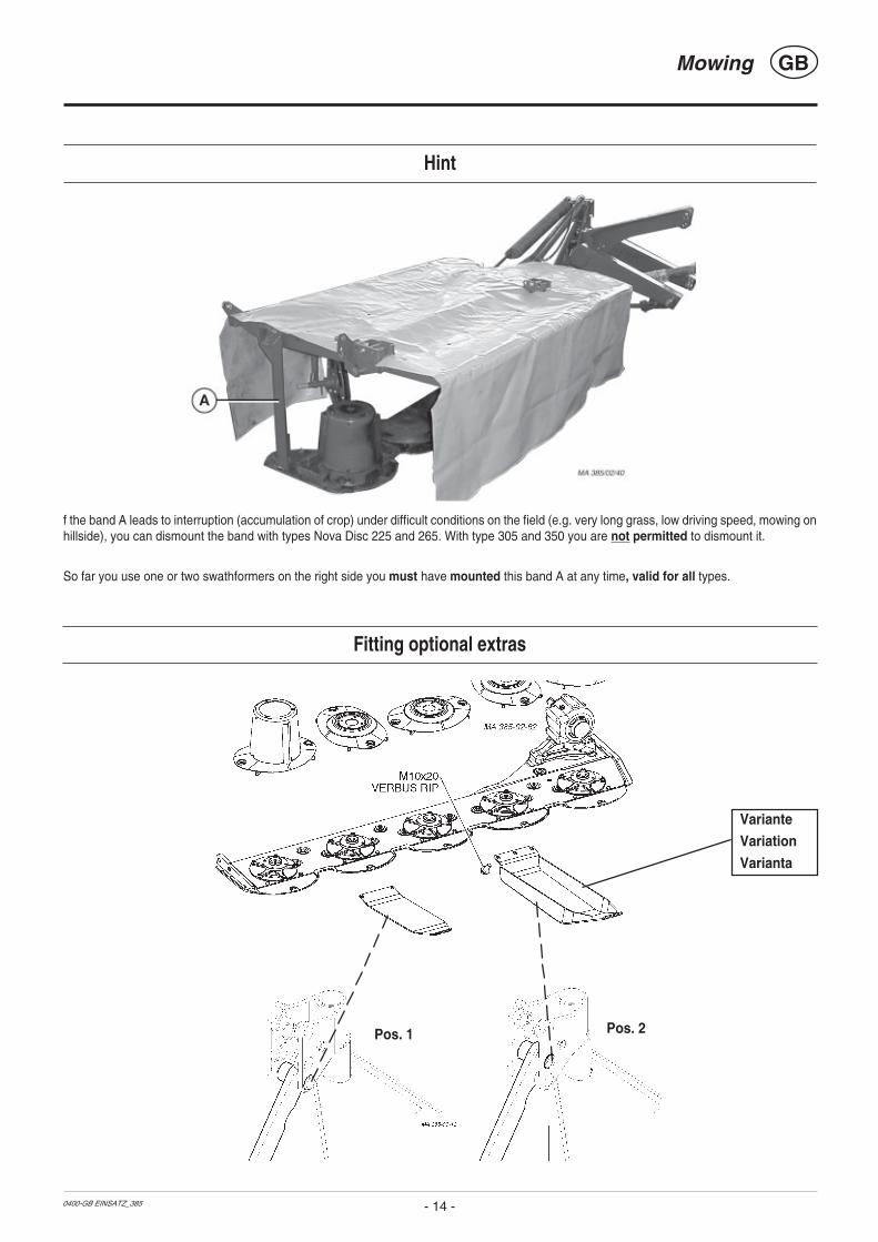
Hint
f the band A leads to interruption (accumulation of crop) under difficult conditions on the field (e.g. very long grass, low driving speed, mowing onhillside), you can dismount the band with types Nova Disc 225 and 265. With type 305 and 350 you are not permitted to dismount it.
So far you use one or two swathformers on the right side you must have mounted this band A at any time, valid for all types.
Pos. 1 Pos. 2
VarianteVariation
Varianta
Fitting optional extras

GBSwathformer
- 15 -0200-GB SCHWADFORMER_385
Swath Discs
With the swath discs a narrower swath is formed when mowing.This prevents them from being run over by the tractor's wide tyres.
NOVADISC 225
NOVADISC 265
NOVADISC 305NOVADISC 350
NOVADISC 265
NOVADISC 305NOVADISC 350
Additional swath discs
Protective apron
Release the protective apron in the swath discs area.
- more information in the supplement of this operating manual
- Only use appropriate tools to cut out!
- The cutting line is the joining between the holes, as shown in the
the supplement of this operating manual.
- Depending on the number of swath discs fitted, select thecorresponding area to be cut
Flat cone conveyor (Optional extra)
- to improve the conveyance rate of swath deposits, particularly
with heavy, thick fodder components
- For individual parts see Spare Parts List
122-
02-3
9

GBSwathformer
- 16 -0200-GB SCHWADFORMER_385

Safety points
• Turn engine off when adjustment,service and repair work is to bedone.
• Do not work under the machinewithout safe support.
• Retighten all screws after the firsthours of operation.
General maintenance hints
In order to keep the implement in good condition after long periods ofoperation, please observe the following points:
- Tighten all screws after the first hours of operation.
In particular check:
- blade screws on the mowers
- tine screws on the swather and tedder.
Spare part
a. The original components and accessories have been designedespecially for these machines and appliances.
b. We want to make it quite clear that components and accesories that havenot been supplied by us have not been tested by us.
c. The installation and/or use of such products can, therefore, negativelychange or influence the construction characteristics of the appliance. Weare not liable for damages caused by the use of components andaccessories that have not been supplied by us.
d. Alterations and the use of auxiliary parts that are not permitted by themanufacturer render all liability invalid.
Repair Instructions
Please refer to repair instructions in supplement (if available)
Cleaning of machine parts
Attention! Do not use high-pressure washers for the cleaning of bearing-and hydraulic parts.
- Danger of rust!
- After cleaning, greasethe machine accordingto the lubrication chartand carry out a shorttest run.
- Cleaning with too highpressure may do damage tovarnish.
Parking in the open
When parking in the open forlong periods of time, cleanpiston rods and then coat withgrease.
Winter storage
- Thoroughly clean machine before storage.
- Put up protection against weather.
- Change or replenish gear oil.
- Protect exposed parts from rust.
- Lubricate all greasing points according to lubrication chart.
Drive shafts
- see notes in the supplementFor maintenance please note!
The instructions in this operating manual are always valid.
In case there are no special instructions available, then the notesin the accompanying drive shaft manufacturer´ instructions arevalid.
Hydraulic unit
Caution! Danger of injury or infection!
Under high pressure, escaping fluids can penetrate the skin.Therefore seek immediate medical help!
After the first 10 operating hours and then everyconsecutive 50 operating hours
- Check the hydraulic unit and lines for tightness and retightenscrew connections if necessary.
Before operation
- Check hydraulic hoses for wear.
Replace worn or damaged hydraulic hoses immediately. Thereplacement hoses must meet the manufacturer’s technicalrequirements.
FETT
TD49/93/2
- 17 -
MAINTENANCE GB
0200-GB ALLG.WARTUNG_358

0400-GB WARTUNG_385
GBMaintenance and Service
- 18 -
Angular gear oil level check
- Change oil after the first 50 operating hours.
Under normal operating conditions, oil is to be replenished annually(OIL LEVEL).
- Change oil after 300 ha at the latest.
Quantity: 0,95 lt. SAE 90
Cutter bar oil level check
• Under normal operating conditions, oil is to be replenished annually.
1. Lift one side of the mower bar (X1) and support.
NOVADISC 225: X1 = 87,0 cm
NOVADISC 265: X1 = 48,0 cm
NOVADISC 305: X1 = 25,0 cm
NOVADISC 350: X1 = 19,0cm• The side where the oil refill screw is located remains on the
ground.
• Lift the other side of the mower bar about X1 and support witha suitable prop..
2. Let mower bar stand in this position for some 15minutes.• This time is necessary to allow the oil to gather in the lower area
of the mower bar.
3. Remove oil refill screw (63).The oil level is measured at the oil refill screw hole.
Important!In doing so the cutter bar must be in horizontal position.
- Take out oil filler plug (63) and top up oil "SAE 90" up to the levelscrew1).
4. Oil level checkThe oil level is correct when the oil comes up to the level screw1)
(OIL LEVEL).
• Too much oil leads to the mower bar overheatingduring operation.
• Too little oil does not guarantee the necessarylubrication
61-00-20
OIL LEVEL
OIL LEVEL
1) The oil filler plug (63) is also the level screw (OIL LEVEL)

0400-GB WARTUNG_385
GBMaintenance and Service
- 19 -
Cutter bar
Changing oil- Change oil after the first 50 operating hours or after 100 ha at the latest.
Note:• Change oil when at operating temperature.
The oil is too viscid when cold. Too much old oil remains stuck to the gearwheels and because of thisany suspended matter present cannot be removed from the gearing
Quantity:
NOVADISC 225: 3,0 Liter SAE 90
NOVADISC 265: 3.5 Liter SAE 90
NOVADISC 305: 4,0 Liter SAE 90
NOVADISC 350: 4.5 Liter SAE 90
- Raise tractor’s lifting gear completely.
- Move hydraulic control device (ST) to”LOWER”
- The outer end of the cutter bar must hangdown.
- Take out oil drain plug (62), let run out and duly dispose waste oil
ST
Installing cutter blades
Take note!
The arrow on the cutter blade shows the cutterdisc's direction of turn.
- To install, clean back plates from varnish.
TD 121-02-06
NOVADISC 265
NOVADISC 225
NOVADISC 350
NOVADISC 305

0400-GB WARTUNG_385
GBMaintenance and Service
- 20 -
Check screws (from 2002 model)
Check screws for tightness every 20 operating hours
Setting Relieving Spring (up to 2002 model)NOVADISC 225 " X " = 120 mm
NOVADISC 265 " X " = 120 mm
NOVADISC 305 " X " = 120 mm
NOVADISC 350 " X " = 120 mm
Setting Relieving Spring (from 2003 model)NOVADISC 225 " X " = 55 mm
NOVADISC 265 " X " = 55 mm
NOVADISC 305 " X " = 55 mm
NOVADISC 350 " X " = 55 mm
Setting Relieving Spring (from 2004 model)NOVADISC 225 " X " = 70 mm
NOVADISC 265 " X " = 70 mm
NOVADISC 305 " X " = 90 mm
NOVADISC 350 " X " = 70 mm
Setting Relieving Spring
In order to prevent turf damage the cutter bar
- must be in an almost parallel position before being set down
- must be set down with the outer end first
- and then the inner side
This is done by adjusting the short relieving spring (MASS ”X”)
If the inner side of cutter bar is to be set down first, increase the tensionof the relieving spring. (MASS ”X” lower)

0400-GB WARTUNG_385
GBMaintenance and Service
- 21 -
V-belt Drive
- check V-belt tension
after 1 hour, after 5 hours, after 20 hours, then asnecessary
Setting range:
0.5 – 3 mm
• Retensioning is only necessary when the settingbecomes more than 3 mm.
• If one of the 3 V-belts is damaged or stretched, then all3 V-belts should be exchanged
IMPORTANT!If the V-belts are tensioned too taut, the danger existsof the bearing and shafts becoming damaged.
Number of fitted V-belts
540 min-1
1000 min-1
122-02-19
540 min-1
1000 min-1
0,5 - 3mm
495.754
NOVADISC 225NOVADISC 265
NOVADISC 305NOVADISC 350

Attention ! Danger of accident if wearingparts are worn
Wearing parts are:- mounting of mowing blades (30)
- bolts of mowing blades (31)
If such wearing parts are worn out they mustnot be used any longer .
Otherwise accidents may be caused throughparts that are flinged away (e.g. mowing blades,fragments...)
Check the suspension of mowing blades as towear and other damage:
- every time before bringing the machine into operational use
- several times during use
- immediately after hitting an obstacle (e.g. a stone, piece of wood,metal,...)
Process of visual control:
1. remove mowing blades
2. remove grass and dirt- around pin (31)
Attention !
Danger of accident if:
- the central part of pin of blade must have a minimum of 15 mm
- the wearing area (30a) has reached the edge of the boring
- the pin of the blade is worn in the lower part (30b)
- the pin of the blade is no longer firmly seated
If you notice one or several of thesecharacteristics of wear stop mowing at once!
Worn parts must be replaced by original partsmade by Pöttinger immediately !
Screw down the pin of the blade with the nutwith 120 Nm.
TD 155-99-20
30a
30b
30
TD 05-00-08
32
min.15 mm
TD 17-99-16e
120 Nm(12 kpm)
GBMOUNTING OF MOWING BLADECHECKING WEAR
- 22 -0000-GB SICHTKONTROLLE (379)

GBMAINTENANCE AND SERVICE
- 23 -0300-GB KLINGEN_385
Holder for a quick change of cutter blades
Attention!
For Your Safety
• Regularly check that cutter blades are tightened firmly!
- Cutter blades on a cutter disc should wear out simultaneously(danger of imbalance).
Otherwise they are to be replaced with new ones (replace inpairs).
- Buckled or damaged cutter blades must not be used further.
• Buckled, damaged and/or worn cutter blade holders (30) shouldnot be used further.
Checking the mowing blade suspension
- Normal check every 50 hours.
- Check more often when mowing on stony terrain or in other difficultoperating conditions.
- Check immediately after driving over a hard obstacle (e.g. stonespieces of wood, ect).
Carry out a check- as described in chapter „Changing the Cutter Blades“
Take note!
Damaged, buckled and worn out parts must not be usedfurther (danger of accident).
30b30
155-99-18
32min.
15 mm
min.15 mm
TD 17-99-16e
120 Nm(12 kpm)
Changing the Cutter Blades (up to 2003 model)
1. Insert lever (H) horizontally between cutter disc andholder (30)
2. Push movable holder (30) down using lever (H).
3. Remove cutter blade (M)4. Clean forage remains and dirt away.
- around the bolts (31) and inside the borehole (32)
5. Check:• blade bolts (31) for damage, wear and fitting
• holder (30) for damage, change in position and fitting
• borehole (32) for damage.
- Side surfaces must not show signs of deformation
6. Fit cutter blades and remove lever (H)• Put the lever (H) in both the recesses in the tool case.
• Close tool case and secure with springclip (V).

GBMAINTENANCE AND SERVICE
- 24 -0300-GB HEBEL-SCHNELLW (379)
Nova Cat 266F / 306F
Nova Alpin 226 Weisteanbau
Nova Disc 225Nova Cat 225/ 265 / 305 / 350
Nova Alpin 226
Changing the Cutter Blades (from 2004 model)
1. Insert lever from left or right side on the cutter disc ”PosA” until it stops.
2. Swing lever from ”pos. A” to ”pos. B” and push themovable holder (30) down.
3. Remove cutter blade (M)
4. Clean forage remains and dirt away. - around the bolts (31) and inside the borehole (32)
Storing the lever
- Place lever in the respective holding pouchand secure.
- See diagrams for storage places.
5. Check:• blade bolts (31) for damage, wear and fitting
• holder (30) for damage, change in position and fitting
• borehole (32) for damage.
- Side surfaces must not show signs of deformation
6. Install cutter blades
7. Visual check! Check that blade (M) is correctly positionedbetween blade bolts (31) and holder (30) (see diagram).
8. Swivel lever (H) to ”A” again and remove.
Pos A
Pos B

GB
0300-GB TECHN. DATEN_385
TECHNICAL DATA
- 25 -
A. P ttinger Maschinenfabrik Ges. m. b. H. A-4710 Grieskirchen Ober sterreich
Modell
Ges.GewType
Masch.Nr.
Ihre/Your/VotreMasch.Nr. / Fgst.Ident.Nr.
Position of Vehicle IdentificationPlate
The factory number is imprinted on the accompanying VehicleIdentification Plate (as shown) and on the frame. Guarantee issues andfurther inquiries cannot be processed without the factory number beingstated.
Please enter the number onto the front page of the operating manualimmediately after taking delivery of the vehicle/implement.
The defined use of the mower unit
TheNOVADISC 225 (Type PSM 385)
NOVADISC 265 (Type PSM 386)
NOVADISC 305 (Type PSM 387)
NOVADISC 350 (Type PSM 388)
mower is intended solely for normal use in agricultural work.• The mowing of grassland and short stemmed fodder.
Any other uses outside of these are regarded as undefined.The manufacturer takes no responsibility for any resultingdamage which occurs henceforth. The risk is carried by the useralone.
• The keeping of operating, service and maintenancerequirements layed down by the manufacturer also come underthe heading of „defined use“.
Optional equipment:
• Warning signs with lighting
• Swath discs
• Flat cone conveyors
• Wearing runners
• High cut runners
Three-point linkage (adjustable)
Working width
No. of mowing discs
No. of knives per disc
Hydraulic lift (single-acting)
Coverage up to
Max. p.t.o. speed
Weight1)
Required power
Free running drive shaft.
Permanent sound emmission level
All data subject to revision.
Technical data
Necessary connections
• 1 x single action hydraulic connection
(minimum necessary tractor fitting)
Operating pressure min : 80 bar
Operating pressure max: 180 barr
NOVADISC 225
(Type PSM 385)
Kat. II
2,25 m
5
2
2,2 ha/h
540 / 1000 min-1
min. 535 kg
ab 30 kW (40 PS)
88,7 dB(A)
NOVADISC 265
(Type PSM 386)
Kat. II
2,62 m
6
2
2,6 ha/h
540 / 1000 min-1
min. 585 kg
ab 37 kW (50 PS)
88,1 dB(A)
NOVADISC 350
(Type PSM 388)
Kat. II
3,46 m
8
2
3,4 ha/h
540 / 1000 min-1
min. 695 kg
ab 52 kW (70 PS)
90,8 dB(A)
NOVADISC 305
(Type PSM 387)
Kat. II
3,04 m
7
2
3,0 ha/h
540 / 1000 min-1
min. 650 kg
ab 44 kW (60 PS)
91,0 dB(A)
1) Weight: Variations possible depending on machine features.

GB-ANHANG TITELBLATT (341)
SUPPLEMENT

GB-ANHANG TITELBLATT (341)
The decision must be made, ”original” or ”imitation”? The decision is often governed byprice and a ”cheap buy” can sometimes be very expensive.
Be sure you purchase the ”Original” with the cloverleaf
symbol!
• Quality and precise fitting
- Operating safety.
• Reliable operation
• Longer lasting
- Economy
• Guaranteed availability through your
Pöttinger Sales Service.
Things will run better with
genuine Pöttinger parts
The original cannot be copied

(341) SICHERHEIT 9400 GB
SUPPLEMENT - A
Recommendations for work safety All points refering to safety in this manual are indicatedby this sign.
1.) Defined usea. See "Technical Data".
b. The keeping of operating, service and maintenancerequirements layed down by the manufacturer also comeunder the heading of "defined use".
2.) Spare partsa. The original components and accessories have been
designed especially for these machines and appliances.
b. We want to make it quite clear that components andaccesories that have not been supplied by us have notbeen tested by us.
c. The installation and/or use of such products can, therefore,
negatively change or influence the constructioncharacteristics of the appliance. We are not liable fordamages caused by the use of components andaccessories that have not been supplied by us.
d. Alterations and the use of auxiliary parts that are notpermitted by the manufacturer render all liability invalid.
3.) Protection devicesAll protection devices must remain on the machine and bemaintained in proper condition. Punctual replacement ofworn and damaged covers is essential.
4.) Before starting worka. Before commencing work, the operator must be aware of
all operating devices and functions. The learning of theseis too late after having already commenced operation!
b. The vehicle is to be tested for traffic and operating safetybefore each operation.
5.) Asbestos- Certain sub-supplied components of the
vehicle may contain asbestos due totechnical reasons. Observe the warningon spare parts.
6.) Transport of persons prohibiteda. The transport of persons on the machine is not permitted.
b. The machine may only be driven on public roads when inthe position stipulated for road transport.
7.) Driving ability with auxiliary equipmenta. The towing vehicle is to be sufficiently equiped with
weights at the front or at the rear in order to guarantee thesteering and braking capacity (a minimum of 20% of thevehicle’s tare weight on the front axle).
b. The driving ability is influenced by ground conditions andby the auxiliary equipment. The driving must be adaptedto the corresponding terrain and ground conditions.
c. When driving through curves with a connected appliance,observe the radius and swinging mass of the appliance.
d. When travelling in a curve with attached or semimountedimplements, take into account the working range andswing mass of the implement!
8.) Generala. Before attaching implement to three-point linkage, move
system lever into a position whereby unintentional raisingor lowering is ruled out!
b. Danger of injury exists when coupling implement to tractor!
c. Danger of injury through crushing and cutting exists in thethree-point linkage area!
d. Do not stand between tractor and implement when usingthree-point linkage external operation!
e. Attach and detach drive shaft only when motor has stopped.
f. When transporting with raised implement, secure operatinglever against lowering!
g. Before leaving tractor, lower attached implement to theground and remove ignition key!
h. Nobody is to stand between tractor and implement withouttractor being secured against rolling using parking brakeand/or wheel chocks!
i. For all maintenance, service and modification work, turndriving motor off and remove universal drive.
9.) Cleaning the machineDo not use high-pressure washers for the cleaning ofbearing- and hydraulic parts.
20%Kg
- A 1 -
Recommendations for work safety
0000-GB GELENKWELLE (341)
DRIVESHAFT GBSupplement - B
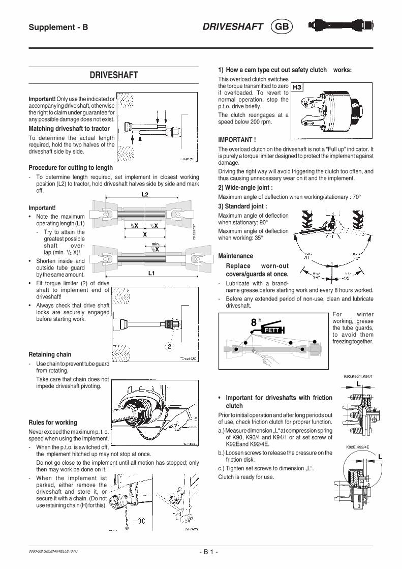
1) How a cam type cut out safety clutch works:This overload clutch switchesthe torque transmitted to zeroif overloaded. To revert tonormal operation, stop thep.t.o. drive briefly.The clutch reengages at aspeed below 200 rpm.
IMPORTANT !The overload clutch on the driveshaft is not a “Full up” indicator. Itis purely a torque limiter designed to protect the implement againstdamage.Driving the right way will avoid triggering the clutch too often, andthus causing unnecessary wear on it and the implement.
2) Wide-angle joint :Maximum angle of deflection when working/stationary : 70°
3) Standard joint :Maximum angle of deflectionwhen stationary: 90°Maximum angle of deflectionwhen working: 35°
MaintenanceReplace worn-outcovers/guards at once.
- Lubricate with a brand-name grease before starting work and every 8 hours worked.
- Before any extended period of non-use, clean and lubricatedriveshaft.
For winterworking, greasethe tube guards,to avoid themfreezing together.
• Important for driveshafts with frictionclutch
Prior to initial operation and after long periods outof use, check friction clutch for proprer function.a.) Measure dimension „L“ at compression spring
of K90, K90/4 and K94/1 or at set screw ofK92Eand K92/4E.
b.) Loosen screws to release the pressure on thefriction disk.
c.) Tighten set screws to dimension „L“.Clutch is ready for use.
DRIVESHAFT
Important! Only use the indicated oraccompanying drive shaft, otherwisethe right to claim under guarantee forany possible damage does not exist.
Matching driveshaft to tractorTo determine the actual lengthrequired, hold the two halves of thedriveshaft side by side.
Procedure for cutting to length- To determine length required, set implement in closest working
position (L2) to tractor, hold driveshaft halves side by side and markoff.
Important!• Note the maximum
operating length (L1)- Try to attain the
greatest possibleshaft over-lap (min. 1/2 X)!
• Shorten inside andoutside tube guardby the same amount.
• Fit torque limiter (2) of driveshaft to implement end ofdriveshaft!
• Always check that drive shaftlocks are securely engagedbefore starting work.
Retaining chain- Use chain to prevent tube guard
from rotating.Take care that chain does notimpede driveshaft pivoting.
Rules for workingNever exceed the maximum p. t. o.speed when using the implement.- When the p.t.o. is switched off,
the implement hitched up may not stop at once.Do not go close to the implement until all motion has stopped; onlythen may work be done on it.
- When the implement istparked, either remove thedriveshaft and store it, orsecure it with a chain. (Do notuse retaining chain (H) for this).
XX
L1
L2
X
Xmin.
TD
52/
97/3
7
- B 1 -
8 h
FETT
L
L
K92E,K92/4E
K90,K90/4,K94/1

- 30 -0200 SCHMIERPLAN_385.P65
9900 LEGENDE-SCHMIERPL / BA/EL ALLG / BETRIEBSSTOFFVORSCHRIFT - 31 -
Schmierplan
8h alle 8 Betriebsstunden20h alle 20 Betriebsstunden
40 F alle 40 Fuhren80 F alle 80 Fuhren
1 J 1 x jährlich100 ha alle 100 Hektar
FETT FETT
= Anzahl der Schmiernippel(IV) Siehe Anhang "Betriebsstoffe"
Liter Liter* Variante
Siehe Anleitung des Herstellers
Plan de graissage
8h Toutes les 8 heures de service20h Toutes les 20 heures de service
40 F Tous les 40 voyages80 F Tous les 80 voyages
1 J 1 fois par an100 ha tous les 100 hectares
FETT GRAISSE
= Nombre de graisseurs(IV) Voir annexe "Lubrifiants"
Liter Litre* Variante
Voir le guide du constructeur
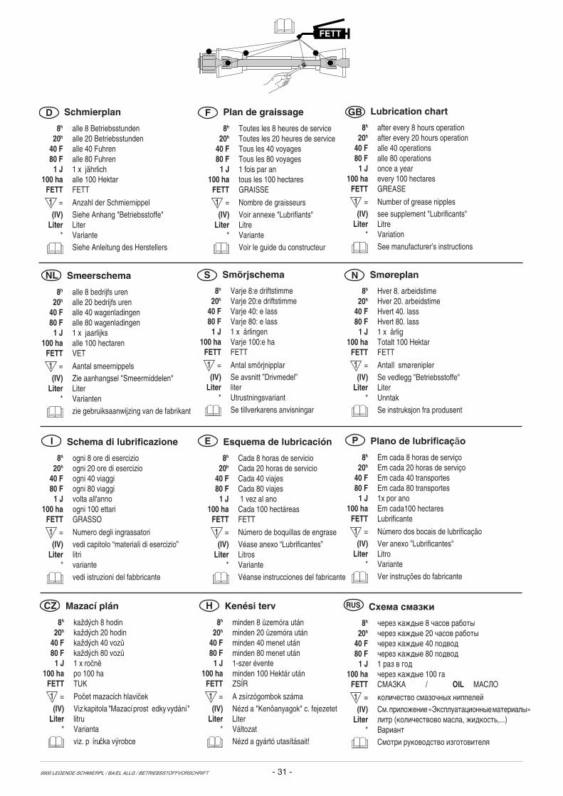
Lubrication chart
8h after every 8 hours operation20h after every 20 hours operation
40 F alle 40 operations80 F alle 80 operations
1 J once a year100 ha every 100 hectares
FETT GREASE
= Number of grease nipples(IV) see supplement "Lubrificants"
Liter Litre* Variation
See manufacturer’s instructions
Smeerschema
8h alle 8 bedrijfs uren20h alle 20 bedrijfs uren
40 F alle 40 wagenladingen80 F alle 80 wagenladingen
1 J 1 x jaarlijks100 ha alle 100 hectaren
FETT VET
= Aantal smeernippels(IV) Zie aanhangsel "Smeermiddelen"
Liter Liter* Varianten
zie gebruiksaanwijzing van de fabrikant
FETT
Schema di lubrificazione
8h ogni 8 ore di esercizio20h ogni 20 ore di esercizio
40 F ogni 40 viaggi80 F ogni 80 viaggi
1 J volta all'anno100 ha ogni 100 ettari
FETT GRASSO
= Numero degli ingrassatori(IV) vedi capitolo “materiali di esercizio”
Liter litri* variante
vedi istruzioni del fabbricante
I Esquema de lubricación
8h Cada 8 horas de servicio20h Cada 20 horas de servicio
40 F Cada 40 viajes80 F Cada 80 viajes
1 J 1 vez al ano100 ha Cada 100 hectáreas
FETT FETT
= Número de boquillas de engrase(IV) Véase anexo “Lubrificantes”
Liter Litros* Variante
Véanse instrucciones del fabricante
Plano de lubrificação
8h Em cada 8 horas de serviço20h Em cada 20 horas de serviço
40 F Em cada 40 transportes80 F Em cada 80 transportes
1 J 1x por ano100 ha Em cada100 hectares
FETT Lubrificante
= Número dos bocais de lubrificação(IV) Ver anexo ”Lubrificantes"
Liter Litro* Variante
Ver instruções do fabricante
E P
NL
D F GB
Smörjschema
8h Varje 8:e driftstimme20h Varje 20:e driftstimme
40 F Varje 40: e lass80 F Varje 80: e lass
1 J 1 x årlingen100 ha Varje 100:e ha
FETT FETT
= Antal smörjnipplar(IV) Se avsnitt ”Drivmedel”
Liter liter* Utrustningsvariant
Se tillverkarens anvisningar
S Smøreplan
8h Hver 8. arbeidstime20h Hver 20. arbeidstime
40 F Hvert 40. lass80 F Hvert 80. lass
1 J 1 x årlig100 ha Totalt 100 Hektar
FETT FETT
= Antall smørenipler(IV) Se vedlegg "Betriebsstoffe"
Liter Liter* Unntak
Se instruksjon fra produsent
N
Mazací plán
8h kaûd˝ch 8 hodin20h kaûd˝ch 20 hodin
40 F kaûd˝ch 40 voz˘80 F kaûd˝ch 80 voz˘
1 J 1 x roËnÏ100 ha po 100 ha
FETT TUK
= PoËet mazacÌch hlaviËek(IV) Viz kapitola "Mazací prost edky vydání "
Liter litru* Varianta
viz. p íruËka v˝robce
Kenési terv
8h minden 8 üzemóra után20h minden 20 üzemóra után
40 F minden 40 menet után80 F minden 80 menet után
1 J 1-szer évente100 ha minden 100 Hektár után
FETT ZSÍR
= A zsírzógombok száma(IV) Nézd a "Kenôanyagok" c. fejezetet
Liter Liter* Változat
Nézd a gyártó utasításait!
CZ H Схема смазки
8h чеpез каждые 8 часов pаботы20h чеpез каждые 20 часов pаботы
40 F чеpез каждые 40 подвод80 F чеpез каждые 80 подвод
1 J 1 pаз в год100 ha чеpез каждые 100 га
FETT СМАЗКА / OIL МАСЛО
= количество смазочных ниппелей
(IV) См. пpиложение «Эксплуатационные матеpиалы»Liter литp (количествово масла, жидкость,...)
* Ваpиант
Смотpи pуководство изготовителя
RUS

Lu
bri
fica
nti
Ed
izio
ne
1997
DG
BI
Bet
rieb
ssto
ffe
Au
sgab
e 19
97
Lu
bri
can
ts
Ed
itio
n 1
997
Leis
tung
und
Leb
ensd
auer
der
Mas
chin
esi
nd v
on s
orgf
ältig
er W
artu
ng u
nd d
erV
erw
endu
ng g
uter
Bet
riebs
stof
fe a
bhän
gig.
Uns
ere
Bet
riebs
stof
fauf
listu
ng e
rleic
hter
td
ie
r ich
tig
e
Au
swa
hl
ge
eig
ne
ter
Bet
riebs
stof
fe.
Im
Sch
mie
rpla
n
ist
de
r je
we
ils
ein
zuse
tze
nd
e
Be
trie
bss
toff
d
urc
h
die
Be
trie
bss
toff
ken
nza
hl
(z.B
. “I
II”)
sym
bo
lisi
ert
. A
nh
an
d
von
“Bet
riebs
stof
fken
nzah
l” ka
nn d
as g
efor
dert
eQ
ualit
ätsm
erkm
al u
nd d
as e
ntsp
rech
ende
Pro
dukt
der
Min
eral
ölfir
men
fes
tges
tel lt
wer
den.
Die
Lis
te d
er M
iner
alöl
firm
en e
rheb
tke
inen
Ans
pruc
h au
f Vol
lstä
ndig
keit.
The
per
form
ance
and
the
lifet
ime
of th
efa
rm m
achi
nes
are
high
ly d
epen
ding
on
a ca
refu
l mai
nten
ance
and
app
licat
ion
of c
orre
ct l
ubri
cant
s. O
ur s
ched
ule
enab
les
an e
asy
sele
ctio
n of
sel
ecte
dpr
oduc
ts.
The
app
licab
le lu
bric
ants
are
sym
boliz
ed(e
g. “
III”)
. A
ccor
ding
to
this
lub
rican
tpr
oduc
t cod
e nu
mbe
r the
spe
cific
atio
n,qu
ality
and
bra
ndna
me
of o
il co
mpa
nies
may
eas
ily b
e de
term
ined
. The
list
ing
ofth
e oi
l co
mpa
nies
is
not
said
to
beco
mpl
ete.
Pre
stat
ies
en l
even
sduu
r va
n de
mac
hine
s zi
jn a
fhan
kelij
k va
n ee
nzo
rgvu
ldig
ond
erho
ud e
n he
t geb
ruik
van
goed
e sm
eerm
idde
len.
Dit
sch
em
a
verg
em
akk
el i j
kt
de
go
ed
e
keu
ze
van
d
e
juis
tesm
eerm
idde
len.
III
IIIIV
VV
IV
II
HY
DR
AU
LIK
öL H
LPD
IN 5
1524
Tei
l 2
Sie
he A
nmer
kung
en* ** **
*
Mot
oren
öl S
AE
30
gem
äßA
PI C
D/S
F
mot
or o
il S
AE
30
acco
rdin
g to
AP
I CD
/SF
huile
mot
eur
SA
E 3
0 ni
veau
AP
I CD
/SF
oilo
mot
ore
SA
E 3
0 se
cond
osp
ecifi
che
AP
I CD
/SF
Get
riebe
öl S
AE
90
bzw
. 85
W-
140
gem
äß A
PI-
GL
5
gear
oil
SA
E 9
0 re
sp. S
AE
85
W-1
40 a
ccor
ding
to A
PI-
GL
5
huile
tran
smis
sion
SA
90
ouS
AE
85
W-1
40, n
ivea
u A
PI G
L5 oi
lio p
er c
ambi
e d
iffer
enzi
ali
SA
E 9
0 o
SA
E 8
5 W
-140
seco
ndo
spec
ifich
e A
PI-
GL
5
Kom
plex
fett
(DIN
51
502:
KP
1R
)
com
plex
gre
ase
grai
sse
com
plex
e
gras
so a
bas
e di
sap
oni
com
ples
si
Get
riebe
fließ
fett
(DIN
51
502:
GO
H
tran
smis
sion
gre
ase
grai
sse
tran
smis
sion
gras
so fl
uido
per
rid
utto
ri e
mot
orod
utto
ri
Li-F
ett (
DIN
51
502,
KP
2K
)
lithi
um g
reas
e
grai
sse
au li
thiu
m
gras
so a
l liti
o
Get
riebe
öl S
AE
90
bzw
. SA
E 8
5 W
-140
gem
äß A
PI-
GL
4 od
er A
PI-
GL
5
gear
oil,
SA
E 9
0 re
sp. S
AE
85
W-1
40ac
cord
ing
to A
PI-
GL
4 or
AP
I-G
L 5
huile
tran
smis
sion
SA
E 9
0 ou
SA
E 8
5 W
-140
, niv
eau
AP
I-G
L 4
ou A
PI-
GL
5
olio
per
cam
bi e
diff
eren
zial
i SA
E 9
0o
SA
E 8
5W-1
40 s
econ
do s
peci
fiche
AP
I-G
L 4
o A
PI-
GL
5
(II)
ÖL
gefo
rder
tes
Qua
lität
smer
kmal
requ
ired
qual
ity le
vel n
ivea
u
de p
erfo
rman
ce d
eman
dé
cara
tteris
tica
richi
esta
di
qual
ità
verla
ngte
kw
alite
itske
nmer
ken
Bet
rieb
ssto
ff-K
enn
zah
lL
ub
rica
nt
ind
icat
or
Co
de
du
lub
rifi
ant
Nu
mer
o c
arat
teri
stic
o d
ellu
bri
fica
nte
Olie
in
aand
rijv
inge
n vo
lgen
s de
gebr
uiks
aanw
ijzin
g ve
rwis
sele
n -
echt
er te
nmin
ste
1 x
jaar
lijks
.-
Afta
pplu
g er
uit
nem
en, d
e ol
ieaf
tapp
en e
n m
ilieu
vrie
ndel
ijkve
rwer
ken.
Ge
trie
be
öl
ge
mä
ß
Be
trie
bsa
nle
itun
g
-je
doch
min
dest
ens
1 x
jähr
lich
wec
hsel
n.-
Öla
blaß
schr
aube
her
ausn
ehm
en, d
asA
ltöl a
usla
ufen
lass
en u
nd o
rdnu
ngs-
gem
äß e
ntso
rgen
.
Ge
ar
oils
a
cco
rdin
g
to
op
era
tin
gin
stru
ctio
ns -
how
ever
at
leas
t on
ce a
year
.-
Tak
e ou
t oil
drai
n pl
ug, l
et ru
n ou
t and
duly
dis
pose
was
te o
il.
Mot
ori
a qu
attr
o te
mpi
: bi
sogn
a ef
fettu
are
il ca
mbi
ode
ll'ol
io o
gni 1
00 o
re d
i fun
zion
amen
to e
que
llo d
ell'o
liope
r cam
bi c
ome
stab
ilito
nel
man
uale
del
le is
truz
ioni
per
l'uso
(tu
ttavi
a, a
lmen
o 1
volta
all'
anno
).-
Tog
liere
il t
appo
di s
caric
o a
vite
del
l’olio
; fa
r sc
olar
el’o
lio e
elim
inar
e l’o
lio c
ome
prev
isto
dal
la le
gge
anti-
inqu
inam
ento
am
bien
tale
.
Sm
eerm
idd
elen
co
de
Vo
or
he
t b
uite
n
ge
bru
ik
ste
llen
(win
terp
eri
od
e)
de
o
lie
-wis
el
uit
voe
ren
e
n
all
e
vetn
ipp
el
smee
rpun
ten
door
smer
en.
Bla
nke
met
aald
elen
(kop
pelin
gen
enz.
) met
een
prod
ukt
uit
groe
p "I
V"
van
dena
volg
ende
tab
el t
egen
cor
rosi
ebe
sche
rmen
.
Bef
ore
gara
ging
(w
inte
r se
ason
) an
oil
chan
ge a
nd g
reas
ing
of a
ll lu
bric
atin
gpo
ints
has
to
be d
one.
Unp
rote
cted
,bl
anc
met
al p
arts
out
side
(jo
ints
, et
c.)
have
to b
e pr
otec
ted
agai
nst c
orro
sion
with
a g
roup
"IV
" pr
oduc
t as
indi
cate
don
the
reve
rse
of th
is p
age.
Sm
eerm
idd
elen
Uit
gav
e 19
97
NL
Lu
bri
fian
ts
Éd
itio
n 1
997
F
Le b
on fo
nctio
nnem
ent e
t la
long
évité
des
mac
hine
s dé
pend
ent d
’un
entr
etie
nso
igne
ux e
t de
l’u
tilis
atio
n de
bon
slu
brifi
ants
. N
otre
lis
te f
acili
te l
e ch
oix
corr
ect d
es lu
brifi
ants
.
Sur
le ta
blea
u de
gra
issa
ge, o
n tr
ouve
un c
ode
(p.e
x."I
II")
se r
éfér
ant
à un
lubr
ifian
t don
né. E
n co
nsul
tant
ce
code
on
p
eu
t fa
cile
me
nt
dé
term
ine
r la
spéc
ifica
tion
dem
andé
e du
lub
rifia
nt.
La l
iste
des
soc
iété
s pé
trol
ière
s ne
prét
end
pas
d’êt
re c
ompl
ète.
Pou
r l’h
uile
tra
nsm
issi
on c
onsu
lter
leca
hier
d’e
ntre
tien
- au
moi
ns u
ne f
ois
par
an.
-R
etire
r le
bouc
hon
de v
idan
ge, l
aiss
erl'h
uil
e
s'é
cou
ler
et
l'éli
min
er
corr
ecte
men
t.
L'ef
ficie
nza
e la
dur
ata
della
mac
chin
a di
pend
ono
dall'
accu
rate
zza
della
sua
man
uten
zion
e e
dall'
impi
ego
dei
lubr
ifica
nti
adat
ti. I
l no
stro
ele
nco
dei
lubr
ifica
nti
Vi
agev
ola
nella
sce
lta d
el lu
brifi
cant
e gi
usto
.
Il lu
brifi
cant
e da
util
izza
rsi d
i vol
ta in
vol
ta è
sim
boliz
zato
nello
sch
ema
di lu
brifi
cazi
one
da u
n nu
mer
o ca
ratte
ristic
o(p
er e
s. "
III")
. In
bas
e al
"nu
mer
o ca
ratte
ristic
o de
llu
brifi
cant
e" s
i po
sson
o st
abili
re s
ia l
a ca
ratte
ristic
a di
qual
ità c
he i
l pr
oget
to c
orris
pond
ente
del
le c
ompa
gnie
petr
olife
re.
L'el
enco
del
le c
ompa
gnie
pet
rolif
ere
non
hapr
etes
e di
com
plet
ezza
.
Vor
Stil
legu
ng (
Win
terp
erio
de)
Ölw
echs
eldu
rchf
ühre
n un
d al
le F
etts
chm
iers
telle
nab
schm
iere
n. B
lank
e M
etal
lteile
auß
en(G
elen
ke, u
sw.)
mit
eine
m P
rodu
kt g
emäß
“IV
” in
der
um
seiti
gen
Tab
elle
vor
Ros
tsc
hütz
en.
Ava
nt
l’arr
êt
et
hiv
er:
vi
da
ng
er
et
grai
sser
. M
étau
x nu
s à
l' ex
téri
eur
prot
éger
ave
c un
pro
duit
type
“IV
” con
tre
la r
ouill
e (c
onsu
lter
tabl
eau
au v
erso
).
Effe
ttuar
e il
cam
bio
dell'
olio
ed
ingr
assa
re tu
tte le
par
ti ch
eric
hied
ono
una
lubr
ifica
zion
e a
gras
so p
rima
del
ferm
oin
vern
ale
della
mac
chin
a. P
rote
gger
e da
lla r
uggi
ne tu
ttele
par
ti m
etal
liche
est
erne
sco
pert
e co
n un
pro
dotto
ano
rma
di "I
V" d
ella
tabe
lla ri
port
ata
sul r
etro
del
la p
agin
a.
(IV)
FE
TT
- D
1 -

-O
SO 3
2/46
/68
ARN
ICA
22/4
6M
OTO
RO
IL H
D 3
0SI
GM
A M
ULT
I 15W
-40
SUPE
R T
RAC
TOR
OIL
UN
IVER
S.15
W-3
0
RO
TRA
HY
80W
-90/
85W
-140
RO
TRA
MP
80W
-90/
85W
-140
GR
MU
2G
R S
LLG
R L
FOR
OTR
A M
P 80
W-9
0R
OTR
A M
P 85
W-1
40
VITA
M G
F 32
/46/
68VI
TAM
HF
32/4
6SU
PER
KO
WAL
30
MU
LTI
TUR
BOR
AL S
UPE
R T
RAK
TOR
AL15
W-3
0
GET
RIE
BEÖ
L EP
90
GET
RIE
BEÖ
LH
YP 8
5W-9
0AR
ALU
B H
L 2
ARAL
UB
FDP
00AR
ALU
B FK
2G
ETR
IEBE
ÖL
HYP
90
AG
IP
AR
AL
*B
ij ge
brui
k op
trek
kers
met
nat
te re
mm
en m
oet
de in
tern
aitio
nale
spec
ifica
tie J
20
Aw
orde
n to
egep
ast
**H
ydra
ulie
kolie
HLP
-(D
)+
HV
***
Hyd
raul
ieko
lie o
ppl
ante
nolie
basi
s H
LP +
HV
is b
iolo
gisc
haf
bree
kbaa
r, da
arom
mili
euvr
iend
elijk
IVA
NM
ER
KU
NG
EN
IIIV
IV
VII
III
Firm
a
Com
pany
Soc
iété
S
ocie
tá(I
V)
FE
TT
(II)
ÖL
*W
hen
wor
king
inco
njun
ctio
n w
ith w
et-
brak
e tra
ctor
s, th
ein
tern
atio
nal
spec
ifica
tion
J 20
A is
nece
ssar
y.
**H
ydra
ulic
oil
HLP
-(D
) + H
V.
***
Hyd
raul
ic o
il w
ithve
geta
ble
oil b
ase
HLP
+ H
V is
bio
-deg
rada
ble
and
is th
eref
ore
espe
cial
ly s
afe
for t
heen
viro
men
t.
HYD
RAU
LIKÖ
L H
LP 3
2/46
/68
SUPE
R 2
000
CD
-MC
*H
YDR
A H
YDR
. FLU
ID *
HYD
RAU
LIKÖ
L M
C 5
30 **
PLAN
TOH
YD 4
0N **
*
SUPE
R 2
000
CD
-MC
SUPE
R 2
000
CD
HD
SU
PER
IOR
20
W-3
0H
D S
UPE
RIO
R S
AE 3
0
SUPE
R 8
090
MC
HYP
OID
80W
-90
HYP
OID
85W
-140
MU
LTI F
ETT
2SP
EZIA
LFET
T FL
MPL
ANTO
GEL
2 N
GET
RIE
BEFL
IESS
FETT
NLG
I 0R
ENO
LIT
DU
RAP
LEX
EP 0
0PL
ANTO
GEL
00N
REN
OPL
EX E
P 1
HYP
OID
85W
-140
BA
YW
A
AVIL
UB
RL
32/4
6AV
ILU
B VG
32/
46M
OTO
RO
IL H
D 3
0M
ULT
IGR
ADE
HD
C 1
5W-4
0TR
ACTA
VIA
HF
SUPE
R 1
0 W
-30
GET
RIE
BEÖ
L M
Z 90
M M
ULT
IHYP
85W
-140
AVIA
MEH
RZW
ECKF
ETT
AVIA
ABS
CH
MIE
RFE
TTAV
IA G
ETR
IEBE
FLIE
SSFE
TTAV
IALU
B SP
EZIA
LFET
T LD
GET
RIE
BEÖ
L H
YP 9
0 EP
MU
LTIH
YP85
W-1
40 E
PA
VIA
ENER
GO
L SH
F 32
/46/
68VI
SCO
200
0EN
ERG
OL
HD
30
VAN
ELLU
S M
30
GEA
R O
IL 9
0 EP
HYP
OG
EAR
90
EPEN
ERG
REA
SE L
S-EP
2FL
IESS
FETT
NO
ENER
GR
EASE
HTO
OLE
X PR
914
2H
YPO
GEA
R 9
0 EP
HYP
OG
EAR
85W
-140
EP
BP
HYS
PIN
AW
S 32
/46/
68 H
YSPI
NAW
H 3
2/46
RX
SUPE
R D
IESE
L 15
W-4
0PO
WER
TRAN
SEP
X 80
W-9
0H
YPO
Y C
80W
-140
IMPE
RVI
A M
MO
CAS
TRO
LGR
EASE
LM
XEP
X 80
W-9
0H
YPO
Y C
80W
-140
CA
ST
RO
L
WIO
LAN
HS
(HG
) 32/
46/6
8W
IOLA
N H
VG 4
6 **
WIO
LAN
HR
32/
46 **
*H
YDR
OLF
LUID
*
MU
LTI-R
EKO
RD
15W
-40
PRIM
ANO
LR
EKO
RD
30
HYP
OID
-GET
RIE
BEÖ
L80
W-9
0, 8
5W-1
40M
EHR
ZWEC
KGET
RIE
BEÖ
L80
W-9
0
WIO
LUB
LFP
2W
IOLU
B G
FWW
IOLU
B AF
K 2
HYP
OID
-GET
RIE
BEÖ
L80
W-9
0, 8
5W-1
40
ENAK
HLP
32/
46/6
8EN
AK M
ULT
I 46/
68SU
PER
EVV
ARO
L H
D/B
SAE
30
UN
IVER
SAL
TRAC
TOR
OIL
SU
PER
HYP
OID
GA
90H
YPO
ID G
B 90
HO
CH
DR
UC
KFET
T LT
/SC
280
GET
RIE
BEFE
TT M
O 3
70EV
VA C
A 30
0H
YPO
ID G
B 90
HLP
32/
46/6
8H
LP-M
M32
/M46
MO
TOR
ÖL
100
MS
SAE
30M
OTO
RÖ
L 10
4 C
M 1
5W-4
0AU
STR
OTR
AC 1
5W-3
0
GET
RIE
BEÖ
L M
P 85
W-9
0G
ETR
IEBE
ÖL
B 85
W-9
0G
ETR
IEBE
ÖL
C 8
5W-9
0
LOR
ENA
46LI
TOR
A 27
RH
ENO
X 34
-G
ETR
IEBE
ÖL
B 85
W-9
0G
ETR
IEBE
ÖL
C 8
5W-1
40
OLN
A 32
/46/
68H
YDR
ELF
46/6
8PE
RFO
RM
ANC
E 2
B SA
E 30
800
0TO
UR
S 20
W-3
0 TR
ACTO
REL
F ST
15W
-30
TRAN
SELF
TYP
B 9
0 85
W-1
40TR
ANSE
LF E
P 90
85W
-140
EPEX
A 2
RO
LEXA
2M
ULT
I 2
GA
O E
PPO
LY G
OM
ULT
IMO
TIVE
1TR
ANSE
LF T
YP B
90
85W
-140
TRAN
SELF
TYP
BLS
80
W-9
0
NU
TO H
32/
46/6
8N
UTO
HP
32/4
6/68
PLU
S M
OTO
RÖ
L 20
W-3
0 U
NIF
ARM
15W
-30
GEA
RO
IL G
P 80
W-9
0 G
EAR
OIL
GP
85W
-140
MU
LTI P
UR
POSE
GR
EASE
HFI
BRAX
EP
370
NEB
ULA
EP
1G
P G
REA
SEG
EAR
OIL
GX
80W
-90
GEA
R O
IL G
X 85
W-1
40
ULT
RAM
AX H
LP 3
2/46
/68
SUPE
RTR
AC F
E 10
W-3
0* U
LTR
AMAX
HVL
P 32
**U
LTR
APLA
NT
40 **
*
SUPE
R H
PO 3
0ST
OU
15W
-30
SUPE
R T
RAC
FE
10W
-30
ALL
FLEE
T PL
US
15W
-40
HP
GEA
R O
IL 9
0od
er 8
5W-1
40TR
ANS
GEA
R O
IL 8
0W-9
0
MU
LTIL
UBE
EP
2VA
L-PL
EX E
P 2
PLAN
TOG
EL 2
N
REN
OLI
T LZ
R 0
00D
EGR
ALU
B ZS
A 00
0D
UR
APLE
X EP
1
TELL
US
S32/
S 46
/S68
TEL
LUS
T32
/T46
AGR
OM
A 15
W-3
0R
OTE
LLA
X 30
RIM
ULA
X 1
5W-4
0
SPIR
AX 9
0 EP
SPIR
AX H
D 9
0SP
IRAX
HD
85/
140
RET
INAX
AAL
VAN
IA E
P 2
SPEZ
. GET
RIE
BEFE
TT H
SIM
MN
IAG
REA
SE O
AER
OSH
ELL
GR
EASE
22
DO
LIU
MG
REA
SE R
SPIR
AX H
D 9
0SP
IRAX
HD
85W
-140
AZO
LLA
ZS 3
2, 4
6, 6
8 EQ
UIV
IS Z
S32
, 46,
68
RU
BIA
H 3
0M
ULT
AGR
I TM
15W
-20
TOTA
L EP
85W
-90
TOTA
L EP
B 8
5W-9
0M
ULT
IS E
P 2
MU
LTIS
EP
200
MU
LTIS
HT
1TO
TAL
EP B
85W
-90
DTE
22/
24/2
5D
TE 1
3/15
HD
20W
-20
DEL
VAC
123
0SU
PER
UN
IVER
SAL
15W
-30
MO
BILU
BE G
X 90
MO
BILU
BE H
D 9
0M
OBI
LUBE
HD
85W
-140
MO
BILG
REA
SE M
PM
OBI
LUX
EP 0
04M
OBI
LPLE
X 47
MO
BILU
BE H
D 9
0M
OBI
LUBE
HD
85W
-140
REN
OPL
EX E
P 1
HYP
OID
EW
90
HYP
OID
85W
-140
HYD
RAU
LIKÖ
L H
LP/3
2/46
/68
HYD
RAM
OT
1030
MC
*H
YDR
AULI
KÖL
520
**PL
ANTO
HYD
40N
***
MU
LTI 2
030
2000
TC
HYD
RAM
OT
15W
-30
HYD
RAM
OT
1030
MC
GET
RIE
BEÖ
L M
P 90
HYP
OID
EW
90
HYP
OID
85W
-140
MEH
RZW
ECKF
ETT
SPEZ
IALF
ETT
GLM
PLAN
TOG
EL 2
N
GET
RIE
BEFL
IESS
FETT
PLAN
TOG
EL 0
0N
HYD
RAN
32/
46/6
8D
ELTA
PLU
S SA
E 30
SUPE
R U
NIV
ERSA
L O
ILPO
NTO
NIC
N 8
5W-9
0 PO
NTO
NIC
MP
85W
-90
85W
-140
SUPE
R U
NIV
ERSA
L O
IL
MAR
SON
EP
L 2
NAT
RAN
00
MAR
SON
AX
2PO
NTO
NIC
MP
85W
-140
REN
OPL
EX E
P 1
REN
OG
EAR
SU
PER
809
0 M
CR
ENO
GEA
R H
YPO
ID 8
5W-1
40R
ENO
GEA
R H
YPO
ID 9
0
TITA
N H
YDR
AMO
T 1O
3O M
CTI
TAN
UN
IVER
SAL
HD
REN
OG
EAR
SU
PER
809
0 M
CR
ENO
GEA
R H
YPO
ID 8
5 W
-140
REN
OG
EAR
HYP
OID
90
REN
OSO
D G
FO 3
5D
UR
APLE
X EP
00
PLAN
TOG
EL 0
0N
ELA
N
FU
CH
S
GE
NO
L
MO
BIL
RH
G
SH
ELL
TO
TA
L
ELF
ES
SO
EV
VA
FIN
A
VA
LVO
LIN
E
VE
ED
OL
REN
OLI
N B
10/
15/2
0 R
ENO
LIN
B32
HVI
/46H
VIEX
TRA
HD
30
SUPE
R H
D 2
0 W
-30
MEH
RZW
EC
KGET
RIE
BEÖ
lSA
E90
HYP
OID
EW
90
MEH
RZW
ECKF
ETT
REN
OLI
T M
PD
UR
APLE
X EP
REN
OSO
D G
FO 3
5R
ENO
PLEX
EP
1H
YPO
ID E
W 9
0
--
AND
ARIN
32/
46/6
8H
D P
LUS
SAE
30M
ULT
IGR
ADE
SAE
80/9
0M
ULT
IGEA
R B
90
MU
LTIG
EAR
C S
AE 8
5W-1
40
MU
LTIP
UR
POSE
MU
LTIG
EAR
B 9
0M
ULT
I C S
AE 8
5W-1
40
WIN
TE
RS
HA
LL
HP
GEA
R O
IL 9
0od
er 8
5W-1
40
REN
OLI
N 1
025
MC
***
TITA
N H
YDR
AMO
T 10
30 M
C **
REN
OG
EAR
HYD
RA
*PL
ANTO
HYD
40N
***
REN
OLI
T M
PR
ENO
LIT
FLM
2R
ENO
LIT
ADH
ESIV
2PL
ANTO
GEL
2 N
CAS
TRO
LGR
EASE
LM
- D
2 -

SUPPLEMENT
- 34 -0300-GB SEITENVERSATZ_385
GB
Attachment variations
The distance between cutting disc and tractor tyres should be asminimal as possible (X1).
Install the console and lower link pins according to the tractor beingused (RL).
Adaption to the tractor
1. Measure the distance to the outer sides of the tractor tyres (RA).
2. Install the console accordingly (RL).
Pos. A (RA = 1800 to 2300 mm)
Pos. B (RA = 2000 to 2600 mm)
3. Insert the lower linkage pins accordingly.
SIDE-LOCATED ATTACHMENT
RA
122-02-32
(up to 2002model)
122-02-44
X12400 mm
Pos. B
50 51
122-02-43
X11900 mm
Pos. A
50 51
(from 2003 model) (up to 2002 model)
Examples:Tractor with a width of RA = 1900 mm
• Console in Pos. A
• Distance X1 = +100 mm / +50 mm / 0 mm
- insert lower linkage pins accordingly (50,51).
(from 2003 model) (up to 2002 model)
Pos. A
Pos. B
Tractor with a width of RA = 2400 mm.
• Console in Pos. B
• Distance X1 = +40 mm / -10 mm / -60 mm
- insert lower linkage pins accordingly (50,51).

AnhangSupplement
AnnexeAanhangsel
- 35 -0200 SCHUTZTUCH_385
AppendiceAnexoP¯ÌlohaP¯ÌlohaP¯ÌlohaP¯ÌlohaP¯ÌlohaMelléklet
MA
385
-02-
53
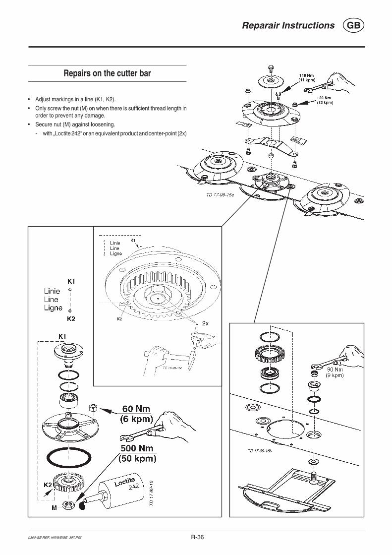
GBReparair Instructions
R-360300-GB REP. HINWEISE_397.P65
Repairs on the cutter bar
• Adjust markings in a line (K1, K2).
• Only screw the nut (M) on when there is sufficient thread length inorder to prevent any damage.
• Secure nut (M) against loosening.
- with „Loctite 242“ or an equivalent product and center-point (2x)
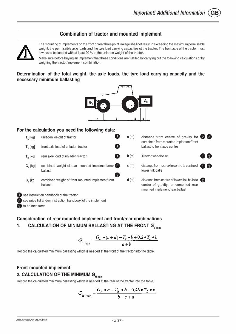
0000-GB ZUSINFO / BA-EL ALLG.
GB
- Z.37 -
see instruction handbook of the tractor
see price list and/or instruction handbook of the implement
to be measured
Consideration of rear mounted implement and front/rear combinations1. CALCULATION OF MINIMUM BALLASTING AT THE FRONT GV min
Record the calculated minimum ballasting which is needed at the front of the tractor into the table.
Front mounted implement2. CALCULATION OF THE MINIMUM GH min
Record the calculated minimum ballasting which is needed at the rear of the tractor into the table.
For the calculation you need the following data:TL [kg]
TV [kg]
TH [kg]
GH [kg]
GV [kg]
unladen weight of tractor
front axle load of unladen tractor
rear axle load of unladen tractor
combined weight of rear mounted implement/rearballast
combined weight of front mounted implement/frontballast
distance from centre of gravity forcombined front mounted implement/frontballast to front axle centre
Tractor wheelbase
distance from rear axle centre to centre oflower link balls
distance from centre of lower link balls tocentre of gravity for combined rearmounted implement/rear ballast
a [m]
b [m]
c [m]
d [m]
2
31
1
1
1
1
2
2
2
3
3
1
3
2
Important! Additional Information
Combination of tractor and mounted implement
The mounting of implements on the front or rear three point linkage shall not result in exceeding the maximum permissibleweight, the permissible axle loads and the tyre load carrying capacities ot the tractor. The front axle of the tractor mustalways to be loaded with at least 20 % of the unladen weight of the tractor.
Make sure before buying an implement that these conditions are fulfilled by carrying out the following calculations or byweighing the tractor/implement combination.
Determination of the total weight, the axle loads, the tyre load carrying capacity and thenecessary minimum ballasting

0000-GB ZUSINFO / BA-EL ALLG.
GB
- Z.38 -
Minimum ballastingfront/rear
Total weight
Front axle load
Rear axle load
Real value according tocalculation
Permissible valueaccording to instruc-
tion handbook
Double permissible tyreload carrying capacity (two
tyres)
The minimum ballasting has to be attached to the tractor either in form of a mountedimplement or ballasting weight!The calculated values must be less or equal (<) the permissible values!
3. CALCULATION OF THE REAL FRONT AXLE LOAD TV tat
(If with the front mounted implement (GV) the required minimum front ballasting (GV min) cannot be reached, the weight of the front mounted implementhas to be increased to the weight of the minimum ballasting at the front!)
Record the calculated real front axle load and the permissible front axle load of the tractor into the table.
4. CALCULATION OF THE REAL TOTAL WEIGHT Gtat
(If with the rear mounted implement (GH) the required minimum rear ballasting (GH min) cannot be reached, the weight of the rear mounted implementshas to be increased to at least the weight of the minimum ballasting at the rear!)
Record the calculated real and the permissible total weight given in the instruction handbook for the tractor into the table.
5. CALCULATION OF THE REAL REAR AXLE LOAD TH tat
Record the calculated real and the permissible rear axle load given in the instruction handbook for the tractor into the table.
6. TYRE LOAD CARRYING CAPACITYRecord double the value (two tyres) of the permissible load carrying capacity into the table (see for instance documentation provided by the tyremanufacturer).
Table
Important! Additional informationCombination of tractor and mounted implement

ALOIS PÖTTINGER Maschinenfabrik Gesellschaft m.b.H.
A-4710 Grieskirchen; Industriegelände 1
9800
D/F
/GB
/NL/
I/E/P
/S/S
F E
G K
onfo
rmitä
tser
kl.
pa. Ing. W. LeposaEntwicklungsleitungGrieskirchen, 06.11.2002
ScheibenmäherNOVADISC 225 Type PSM 385NOVADISC 265 Type PSM 386NOVADISC 305 Type PSM 387NOVADISC 350 Type PSM 388
EN 292-1 : 1991 EN 292-2 : 1991
Appendix 1
GB
________________________ ________________________________(Place and date of issue) (Name and job function of authorized person)
EC Certificate of Conformityconforming to EEC Directions 98/37
We _______________________________________________________________________(name of supplier)
_________________________________________________________________________(full address of company - where this concerns authorized agents within the Common Market, also state the companyname and manufacturer)
declare in sole responsibility, that the product
_________________________________________________________________________(make, model)
to which this certificate applies, conforms to the basic safety and health requirements ofEEC Directions 98/37,(if applicable)and to the other relevant EEC Directions.
_________________________________________________________________________(title and/or number and date of issue of the other EEC Directions)
(if applicable)To effect correct application of the safety and health requirements stated in the EEC Directions,the following standards and/or technical specifications were consulted:
_________________________________________________________________________(title and/or number and date of issue of standards and/or specifications)

Following the policy of the PÖTTINGERGes.m.b.H to improve their products as
technical developments continue, PÖTTINGER reservethe right to make alterations which must not necessarilycorrespond to text and illustrations contained in thispublication, and without incurring obligation to alterany machines previously delivered.
Technical data, dimensions and weights are given asan indication only. Responsibility for errors or omissionsnot accepted.
Reproduction or translation of this publication, in wholeor part, is not permitted without the written consent ofthe ALOIS PÖTTINGER
Maschinenfabrik Gesellschaft m.b.H.
A-4710 Grieskirchen.
All rights under the provision of the Copyright Act arereserved.
La société PÖTTINGER Ges.m.b.H amélioreconstamment ses produits grâce au progrès
technique. C'est pourquoi nous nous réservons le droitde modifier descriptions et illustrations de cette noticed'utilisation, sans qu'on en puisse faire découler undroit à modifications sur des machines déjà livrées.
Caractéristiques techniques, dimensions et poids sontsans engagement. Des erreurs sont possibles.
Copie ou traduction, même d'extraits, seulement avecla permission écrite de
ALOIS PÖTTINGER
Maschinenfabrik Gesellschaft m.b.H.
A-4710 Grieskirchen.
Tous droits réservés selon la réglementation des droitsd'auteurs.
De PÖTTINGER Ges.m.b.H werkt perma-nent aan de verbetering van hun produkten in
het kader van hun technische ontwikkelingen. Daarommoeten wij ons veranderingen van de afbeeldingen enbeschrijvingen van deze gebruiksaanwijzingvoorbehouden, zonder dat daaruit een aanspraak opveranderingen van reeds geieverde machines kanworden afgeleid.
Technische gegevens, maten en gewichten zijn nietbindend. Vergissingen voorbehouden.
Nadruk of vertaling, ook gedeeltelijk, slechts metschiftelijke toestemming van de
ALOIS PÖTTINGER
Maschinenfabrik Gesellschaft m.b.H.
A-4710 Grieskirchen.
Alle rechten naar de wet over het auteursrechtvoorbehouden.
La empresa PÖTTINGER Ges.m.b.H seesfuerza contínuamente en la mejora
constante de sus productos, adaptándolos a laevolución técnica. Por ello nos vamos obligados areservarnos todos los derechos de cualquiermodificación de los productos con relación a lasilustraciones y a los textos del presente manual, sinque por ello pueda ser deducido derecho alguno a lamodificación de máquinas ya suministradas.
Los datos técnicos, las medidas y los pesos seentienden sin compromiso alguno.
La reproducción o la traducción del presente manualde instrucciones, aunque sea tan solo parcial, requierede la autorización por escrito de
ALOIS PÖTTINGER
Maschinenfabrik Gesellschaft m.b.H.
A-4710 Grieskirchen.
Todos los derechos están protegidos por la ley de lapropiedad industrial.
D
NL
GBF
E
Im Zuge der technischen Weiterentwicklungarbeitet die PÖTTINGER Ges.m.b.H ständig
an der Verbesserung ihrer Produkte.
Änderungen gegenüber den Abbildungen und Be-schreibungen dieser Betriebsanleitung müssen wiruns darum vorbehalten, ein Anspruch auf Änderungenan bereits ausgelieferten Maschinen kann daraus nichtabgeleitet werden.
Technische Angaben, Maße und Gewichte sind unver-bindlich. Irrtümer vorbehalten.
Nachdruck oder Übersetzung, auch auszugsweise,nur mit schriftlicher Genehmigung der
ALOIS PÖTTINGER
Maschinenfabrik Gesellschaft m.b.H.
A-4710 Grieskirchen.
Alle Rechte nach dem Gesetz des Urheberrecht vorbe-halten.
La PÖTTINGER Ges.m.b.H è costantementeal lavoro per migliorare i suoi prodotti
mantenendoli aggiornati rispetto allo sviluppo dellatecnica.
Per questo motivo siamo costretti a riservarci la facoltàdi apportare eventuali modifiche alle illustrazioni e alledescrizioni di queste istruzioni per l’uso. Allo stessotempo ciò non comporta il diritto di fare apportaremodifiche a macchine già fornite.
I dati tecnici, le misure e i pesi non sono impegnativi.Non rispondiamo di eventuali errori. Ristampa otraduzione, anche solo parziale, solo dietro consensoscritto della
ALOIS PÖTTINGER
Maschinenfabrik Gesellschaft m.b.H.
A-4710 Grieskirchen.
Ci riserviamo tutti i diritti previsti dalla legge sul dirittod’autore.
I
V d˘sledku technickÈho v˝voje pracujefirma PÖTTINGER Ges.m.b.H neust·le
na zlepöenÌ sv˝ch v˝robk˘.
ZmÏny v n·vodu k pouûÌv·nÌ si v˝robce vyhrazuje.Poûadavky na zmÏnu n·vodu k pouûÌv·nÌ napr·vÏ dodanÈ stroje nemohou b˝t vyvozov·ny.
TechnickÈ ˙daje, rozmÏry a hmotnosti jsounez·vaznÈ.
Dotisk nebo nov˝ p¯eklad je moûn˝ pouze zapÌsemnÈho souhlasu firmy
ALOIS PÖTTINGER
Maschinenfabrik Gesellschaft m.b.H.
A-4710 Grieskirchen
Vöechna pr·va podlÈhajÌ autorskÈmu pr·vu.
CZ В ходе технического развития фирма«ПЁТТИНГЕР Гез.м.б.Х.» постояннозанимается усовершенствованием своей
продукции.
В связи с этим мы сохраняем за собой право вноситьизменения в рисунки и описания этой инструкции поэксплуатации, однако,требование вносить такиеизменения в уже поставленные машины предъявлениюне подлежит.
Технические данные, указание размеров и массы даютсябез обязательств. Ошибки не исключены.
Перепечатка или перевод, в том числе отрывками,разрешается только с письменного согласия фирмы
«АЛОЙС ПЁТТИНГЕР
Машиненфабрик Гезельшафт м.б.Х.»
А-4710 Грискирхен.
С сохранением всех прав в соответствии с авторскимправом.
RUS
S Beroende på den tekniska utvecklingenarbetar PÖTTINGER Ges.m.b.H. på att
förbättra sina produkter.
Vi måste därför förbehålla oss förändringar gentemotavbildningarna och beskrivningarna i dennabruksanvisning. Däremot består det inget anspråk påförändringar av produkter beroende av dennabruksanvisning.
Tekniska uppgifter, mått och vikter är oförbindliga. Felförbehållna.
Ett eftertryck och översättningar, även utdrag, får endastgenomföras med skriftlig tillåtelse av
ALOIS PÖTTINGER
Maschinenfabrik Gesellschaft m.b.H.
A – 4710 Grieskirchen
Alla rättigheter enligt lagen om upphovsmannarättenförbehålls.
A mûszaki termékfejlesztés folyamatában aPöttinger Ges.m.b.H. folyamatosan dolgozik
termékei minôségének javításán.Ezen kezelési utasítás ábráinak és leírásainakváltoztatási jogát fenntartjuk, emiatt nem lehetköveteléssel fellépni egy már kiszállított gépmegváltoztatásával kapcsolatban.A mûszaki adatok, méretek, tömegek, kötelezettségnélküliek. A tévedések joga fenntartva.Utánnyomás vagy fordítás, akárcsak kivonatosan is,csak azALOIS PÖTTINGERMaschinenfabrik Gesellschaft m.b.H.A-4710 Grieskirchen írásos engedélyével történhet.A szerzôi jogi törvény értelmében minden jog fenntartva.
HU
PLW sensie dalszego rozwoju technicznegoPoettinger nieustannie pracuje nadulepszaniem swoich produktÛw. W zwiπzku z
powyøszym zastrzegamy sobie prawo do zmian wschematach i opisach znajdujπcych siÍ w niniejszejinstrukcji obs≥ugi.Nie wyklucza siÍ prawa do zmian rÛwnieø w przypadkujuø dostarczonych maszyn.Dane techniczne, wymiary i ciÍøary nie sπ wielkoúciamiostatecznymi. Dopuszcza siÍ moøliwoúÊ pojawieniasiÍ b≥edÛw.Powielanie bπdü t≥umaczenia, rÛwnieø wyrywkowe,wy≥πcznie za pisemnπ zgodπALOIS POTTINGERMaschinenfabrik Gesellschaft m.b.H.A-4710 GrieskirchenWszelkie prawa w≥πcznie z prawami autorskimizastrzeøone.

GEBR. PÖTTINGER GMBHServicezentrumSpöttinger-Straße 24Postfach 1561D-86 899 LANDSBERG / LECHTelefon:
Ersatzteildienst: 0 81 91 / 92 99 - 166 od. 169Kundendienst: 0 81 91 / 92 99 - 130 od. 231
Telefax: 0 81 91 / 59 656
ALOIS PÖTTINGERMaschinenfabrik Gesellschaft m.b.HA-4710 Grieskirchen
Telefon: 0043 (0) 72 48 600-0Telefax: 0043 (0) 72 48 600-511
e-Mail: [email protected]: http://www.poettinger.co.at
GEBR. PÖTTINGER GMBHStützpunkt NordWentruper Mark 10D-48 268 GrevenTelefon: (0 25 71) 93 45 - 0
Ersatzteildienst: (0 25 71) 93 45 - 11Kundendienst: (0 25 71) 93 45 - 12
Telefax: (0 25 71) 93 45 - 14
PÖTTINGER France129 b, la ChapelleF-68650 Le Bonhomme
Tél.: 03.89.47.28.30Fax: 03.89.47.28.39