
High-sensitive optical measurement of spin polarization in a

MIL-STD-810F NOTICE 35 May 2003
DEPARTMENT OF DEFENSETEST METHOD STANDARD
ENVIRONMENTAL ENGINEERING CONSIDERATIONS AND LABORATORY TESTS
TO ALL HOLDERS OF MIL-STD-810F:1. THE FOLLOWING PAGES OF MIL-STD-810F HAVE BEEN REVISED AND SUPERSEDE THE PAGESLISTED:
NEW PAGE DATE SUPERSEDED PAGE DATEPart One-3 5 May 2003 Part One-3 30 August 2002Part One-4 30 August 2002 Part One-4 REPRINTED WITHOUT CHANGEPart One-23 5 May 2003 Part One-23 30 August 2002Part One-24 5 May 2003 Part One-24 30 August 2002
501.4-3 1 January 2000 501.4-3 REPRINTED WITHOUT CHANGE501.4-4 5 May 2003 501.4-4 30 August 2002505.4-3 5 May 2003 505.4-3 30 August 2002505.4-4 30 August 2002 505.4-4 REPRINTED WITHOUT CHANGE506.4-1 30 August 2002 506.4-1 REPRINTED WITHOUT CHANGE506.4-2 5 May 2003 506.4-2 1 January 2000506.4-3 5 May 2003 506.4-3 30 August 2002506.4-4 30 August 2002 506.4-4 REPRINTED WITHOUT CHANGE506.4-7 5 May 2003 506.4-7 30 August 2002506.4-8 30 August 2002 506.4-8 REPRINTED WITHOUT CHANGE506.4-9 30 August 2002 506.4-9 REPRINTED WITHOUT CHANGE506.4-10 5 May 2003 506.4-10 1 January 2000507.4-1 30 August 2002 507.4-1 REPRINTED WITHOUT CHANGE507.4-2 5 May 2003 507.4-2 30 August 2002507.4-3 5 May 2003 507.4-3 1 January 2000507.4-4 1 January 2000 507.4-4 REPRINTED WITHOUT CHANGE507.4-5 1 January 2000 507.4-5 REPRINTED WITHOUT CHANGE507.4-6 5 May 2003 507.4-6 30 August 2002507.4-7 5 May 2003 507.4-7 30 August 2002507.4-8 1 January 2000 507.4-8 REPRINTED WITHOUT CHANGE
AMSC N/A AREA ENVR
DISTRIBUTION STATEMENT A. Approved for public release; distribution is unlimited.
NOTICE OFCHANGE
NOT MEASUREMENTSENSITIVE
Downloaded from http://www.everyspec.com

MIL-STD-810FNOTICE 35 May 2003
2
NEW PAGE DATE SUPERSEDED PAGE DATE508.5-1 5 May 2003 508.5-1 30 August 2002508.5-2 1 January 2000 508.5-2 REPRINTED WITHOUT CHANGE508.5-3 1 January 2000 508.5-3 REPRINTED WITHOUT CHANGE508.5-4 5 May 2003 508.5-4 1 January 2000508.5-9 5 May 2003 508.5-9 30 August 2002508.5-10 30 August 2002 508.5-10 REPRINTED WITHOUT CHANGE
509.4-1 5 May 2003 509.4-1 1 January 2000509.4-2 1 January 2000 509.4-2 REPRINTED WITHOUT CHANGE509.4-7 5 May 2003 509.4-7 30 August 2002509.4-8 1 January 2000 509.4-8 REPRINTED WITHOUT CHANGE510.4-5 5 May 2003 510.4-5 1 January 2000510.4-6 1 January 2000 510.4-6 REPRINTED WITHOUT CHANGE510.4-9 1 January 2000 510.4-9 REPRINTED WITHOUT CHANGE510.4-10 5 May 2003 510.4-10 30 August 2002514.5-5 5 May 2003 514.5-5 1 January 2000514.5-6 1 January 2000 514.5-6 REPRINTED WITHOUT CHANGE514.5A-3 1 January 2000 514.5A-3 REPRINTED WITHOUT CHANGE514.5A-4 5 May 2003 514.5A-4 1 January 2000514.5A-5 5 May 2003 514.5A-5 1 January 2000514.5A-6 30 August 2002 514.5A-6 REPRINTED WITHOUT CHANGE514.5A-13 5 May 2003 514.5A-13 1 January 2000514.5A-14 30 August 2002 514.5A-14 REPRINTED WITHOUT CHANGE514.5C-1 1 January 2000 514.5C-1 REPRINTED WITHOUT CHANGE514.5C-2 5 May 2003 514.5C-2 1 January 2000514.5C-3 5 May 2003 514.5C-3 1 January 2000514.5C-4 30 August 2002 514.5C-4 REPRINTED WITHOUT CHANGE514.5C-5 5 May 2003 514.5C-5 30 August 2002514.5C-6 5 May 2003 514.5C-6 1 January 2000514.5C-7 5 May 2003 514.5C-7 30 August 2002514.5C-8 30 August 2002 514.5C-8 REPRINTED WITHOUT CHANGE514.5C-9 5 May 2003 514.5C-9 30 August 2002514.5C-10 1 January 2000 514.5C-10 REPRINTED WITHOUT CHANGE516.5-27 5 May 2003 516.5-27 1 January 2000516.5-28 5 May 2003 516.5-28 1 January 2000518-1 5 May 2003 518-1 1 January 2000518-2 5 May 2003 518-2 1 January 2000518-3 5 May 2003 518-3 1 January 2000518-4 5 May 2003 518-4 1 January 2000518-5 5 May 2003 518-5 1 January 2000518-6 5 May 2003 518-6 1 January 2000520.2-11 5 May 2003 520.2-11 30 August 2002520.2-12 1 January 2000 520.2-12 REPRINTED WITHOUT CHANGE520.2A-3 5 May 2003 520.2A-3 30 August 2002520.2A-4 1 January 2000 520.2A-4 REPRINTED WITHOUT CHANGE .
Downloaded from http://www.everyspec.com

MIL-STD-810FNOTICE 35 May 2003
3
2. RETAIN THIS NOTICE AND INSERT BEFORE TABLE OF CONTENTS.
3. Holders of MIL-STD-810F will verify that page changes indicated above have been entered. This notice pagewill be retained as a check sheet. This issuance, together with appended pages, is a separate publication. Eachnotice is to be retained by stocking points until the standard is completely revised or canceled.
Custodians: Preparing activity:Army – TE Air Force – 11Navy – AS (Project ENVR-0051)Air Force – 11
Review activities:Army – AR, AT, AV, CE, CR, GL, MI, MT, SMNavy – CH, EC, MC, OS, SH, YDAir Force – 13, 19
Downloaded from http://www.everyspec.com

Downloaded from http://www.everyspec.com

MIL-STD-810F5 May 2003
Part One-3
2. APPLICABLE DOCUMENTS2.1 General. The documents listed in this paragraph are referenced in Part TWO of this standard. There are other documentscited in Part TWO of this standard that are recommended for additional information or as examples. While everyeffort has been made to ensure the completeness of this list, document users are cautioned that they should considerall specified requirements documents and tasks cited in paragraph 4 of this standard.
2.2 Government documents
2.2.1 Specifications, standards, and handbooks. The following specifications, standards, and handbooks form a part of this document to the extent specified herein. When applying a portion of this standard that contains one of these references, cite the particular edition of thedocument that is listed in the current Department of Defense Index of Specifications and Standards (DoDISS), or inthe DoDISS that was in effect at the time of solicitation. Unless otherwise specified, the issues of these documentsare those listed in the issue of the DoDISS and supplement thereto, cited in the solicitation (see paragraph 6.2).
SPECIFICATIONSMIL-S-901 Shock Tests, H.I. (High Impact) Shipboard Machinery, Equipment, and Systems, Requirements for
STANDARDSMIL-STD-331 Fuze and Fuze Components, Environmental and Performance Tests forMIL-STD-882 Standard Practice for System Safety
HANDBOOKSMIL-HDBK-310 Global Climatic Data for Developing Military Products
(Copies of the above documents are available from the Document Automation and Production Service, Building4/D, 700 Robbins Avenue, Philadelphia PA 19111-5094; http://assist.daps.dla.mil.)2.2.2 Other government documents.The following other Government documents and publications form a part of this document to the extent specifiedherein. Unless otherwise specified, the issues are those cited in the solicitation.DIRECTIVES, INSTRUCTIONS, AND MANUALS
DoDD 5000.1 The Defense Acquisition SystemDoDI 5000.2 Operation of the Defense Acquisition SystemDoD 5000.2-R Mandatory Procedures for Major Defense Acquisition Programs (MDAPS) and Major
Automated Information System (MAIS) Acquisition Programs(Copies of the above documents may be downloaded from www.deskbook.osd.mil.)
PUBLICATIONSAR 70-38 Research, Development, Test and Evaluation of Materiel for Extreme Climatic Conditions
(Copies of the above document are available from the U.S. Army Publications Distribution Center, 1655 WoodsonRd., St. Louis MO 63114-6181; telephone [314] 263-7305.)2.3 Non-government documents. The following documents form a part of this document to the extent specified herein. Unless otherwise specified,the issues of the documents that are DoD adopted are those listed in the issue of the DoDISS cited in thesolicitation. Unless otherwise specified, the issues of documents not listed in the DoDISS are the issues of thedocuments cited in the solicitation (see 6.2).
SUPERSEDES PAGE PART ONE-3 OF NOTICE 2 TO MIL-STD-810F.
Downloaded from http://www.everyspec.com

MIL-STD-810F 30 August 2002
Part One-4
STANAG 2895 Extreme Climatic Conditions and Derived Conditions for Use in Defining Design TestCriteria for NATO Forces Materiel
STANAG 4242 Vibration Tests for Munitions Carried in Tracked VehiclesSTANAG 4370 Environmental TestingQSTAG 360 Climatic Environmental Conditions Affecting the Design of Military MaterielAECTP 100 Allied Environmental Conditions and Test Publication (AECTP) 100, Environmental
Guidelines for Defence Materiel (under STANAG 4370)AECTP 200 Allied Environmental Conditions and Test Publication (AECTP) 200, Environmental
Conditions (under STANAG 4370)AECTP 300 Allied Environmental Conditions and Test Publication (AECTP) 300, Climatic
Environmental Tests (under STANAG 4370)AECTP 400 Allied Environmental Conditions and Test Publication (AECTP) 400, Mechanical
Environmental Tests (under STANAG 4370)(Copies of the above documents are available from the Document Automation and Production Service, Building4/D, 700 Robbins Avenue, Philadelphia PA 19111-5094; http://assist.daps.dla.mil.)
AMERICAN NATIONAL STANDARDS INSTITUTE (ANSI)
National Conference of Standards Labs (NCSL)ANSI NCSL Z540-1 General Requirements for Calibration Laboratories and Measuring and Test Equipment
INTERNATIONAL ORGANIZATION FOR STANDARDIZATION (ISO) STANDARDSISO 10012-1 Quality Assurance Requirements for Measuring Equipment - Part I: Meteorological
Confirmation System for Measuring Equipment First Edition(Copies of the above documents are available from American National Standards Institute (ANSI), 25 West 43rd Street,4th Fl, New York NY 10036-7406 ; telephone [212] 642-4900; www.ansi.org.)
2.4 Order of precedence.In the event of a conflict between the text of this document and the references cited herein, the text of this documenttakes precedence. Nothing in this document, however, supersedes applicable laws and regulations unless a specificexemption has been obtained.
3. DEFINITIONS.
3.1 Terms.This terminology section is meant to define the general terminology as it is used in this standard. In certain casesthe terminology use may be somewhat different from its use in the general engineering community. No attempt hasbeen made to be complete, therefore limiting the glossary to such terms as are found in the standard and that areimportant to the application of the standard. Terminology unique to a particular method is defined, as appropriate,in that method.NOTE: A continuation of this terminology section that contains terminology more closely related to the dynamic(mechanical) test methods such as vibration, shock, gunfire vibration, etc., is in Part One Appendix D.
a. Accelerated test. A test designed to shorten the controlled environmental test time with respect to theservice use time by increasing the frequency of occurrence, amplitude, duration, or any combination ofthese of environmental stresses that would be expected to occur during service use.
b. Aggravated test. A test in which one or more conditions are set at a more stressful level than themateriel will encounter during service use.
REPRINTED WITHOUT CHANGE.
Downloaded from http://www.everyspec.com

MIL-STD-810F5 May 2003
Part One-23
degradation. Other minimum intervals may be set to capture transient events that may occur at any timeduring the test.
5.18.3 Total High Temperature Exposure Duration. The total materiel temperature conditioning exposure duration time for the test program should be less than the lifeexpectancy time of any component material. Determine the total exposure time from the sum of the pre-conditioning time, plus any standby time, plus actual laboratory testing time. A total exposure duration greater thanthe materiel life limit can create an accelerated material failure mode or materiel degradation that is unrelated to thesimulated environmental test condition. In particular, use caution during testing of energetic or chemically-reactivematerials that degrade under elevated temperature conditions. To determine the total exposure time, the testprogram engineer must consider each phase of environmental testing, mechanical climatic and electrical, and anyadditional standby time prior to final operational or performance tests. Standby or pre-conditioning time, such asmaintaining the item at conditioned temperature over a weekend, can have a significant impact. The actual testconditions concern the duration for high temperature storage and operational tests, high temperature soaks duringvibration, and possibly solar radiation tests.
6. NOTES.(This paragraph contains information of a general or explanatory nature that may be helpful.)
6.1 Intended use. This standard is intended to organize and standardize the approach within the materiel acquisition process forconsidering how environmental stresses affect materiel design, test, and evaluation. It emphasizes tailoring materielto withstand the stresses it is intended to experience during its life cycle, and testing such materiel accordingly. Theintended result is to eliminate over- and under-designed/tested materiel with respect to environmental stresses, toensure environmental considerations are addressed systematically, to ensure test plans are tailored realistically aswell as thoroughly, to ensure test execution adheres to tailored test plans, and to ensure test reports are complete andmeaningful.
6.2 Issue of DoDISS. When this standard is used in acquisition, the applicable issue of the DoDISS must be cited in the solicitation (seeparagraphs 2.2.1 and 2.3).
6.3 Subject term (key word) listing. (Also see Subject Index, page Index-1.)AccelerationAcidic AtmosphereAcoustic NoiseClimatic EnvironmentDustEnvironmental Life CycleEnvironmental Test ProceduresEnvironmental Test ReportExplosive AtmosphereFluid ContaminationFungusGunfire VibrationHumidityImmersionInduced EnvironmentLow Pressure (Altitude)Natural Environment
SUPERSEDES PAGE PART ONE-23 OF NOTICE 2 TO MIL-STD-810F.
Downloaded from http://www.everyspec.com

MIL-STD-810F5 May 2003
Part One-24
RainSalt FogSandShockSolar RadiationTemperatureTemperature ShockVibration
6.4 International Standardization Agreement. Certain provisions of this standard are the subject of international standardization agreementsSTANAG’s 2895, 4242, and 4370. When proposed amendments, revisions, or cancellation of this standard willmodify the international agreement concerned, the Preparing Activity will take appropriate action throughinternational standardization channels, including departmental standardization offices, to change the agreement ormake other appropriate accommodations.
6.5 Changes from previous issue. This document is a complete rewrite of MIL-STD-810E. Due to the extensive modifications, asterisks or verticallines are not used to identify changes from the previous issue. Changes to MIL-STD-810F will be published inChange Notices.
Custodians: Preparing activity: Army – TE Air Force – 11 Navy – AS Air Force – 11 Project No.
ENVR-0045
Review activities: Army – AR, AT, AV, CE, CR, GL, MI, MT, SM Navy – CH, EC, MC, OS, SH, YD Air Force – 13, 19
International interest (See paragraph 6.4.)
SUPERSEDES PAGE PART ONE-24 OF NOTICE 2 TO MIL-STD-810F.
Downloaded from http://www.everyspec.com

MIL-STD-810F1 January 2000
METHOD 501.4501.4-3
e. Other significant heat sources that could affect the materiel such as motors, engines, power supplies, orexhaust air.
2.2.2 Difference between procedures. While both procedures involve temperature conditioning and performance testing, they differ on the basis of thetemperature load prior to and during performance tests. The storage procedure assesses the effects of hightemperature storage on subsequent materiel performance. The operation procedure assesses the effects of hightemperatures during performance.
a. Procedure I - Storage. Use Procedure I to investigate how high temperatures during storage affect themateriel (integrity of materials, and safety/performance of the materiel). This test procedure includesexposing the test item to high temperatures (and low humidity where applicable) that may beencountered in the materiel's storage situation, followed by a performance test at standard or hightemperature ambient conditions.
b. Procedure II - Operation. Use Procedure II to investigate how high ambient temperatures may affectmateriel performance while it is operating. There are two ways to perform Procedure II:(1) Expose the test item to cyclic chamber conditions with the test item operating either continuously or
during the period of maximum response (highest item temperature).
(2) Expose the test item to a constant temperature and operate the test item when its temperaturestabilizes.
2.3 Determine Test Levels and Conditions. Having selected this method and relevant procedures (based on the test item's requirements documents and thetailoring process), complete the tailoring process by identifying appropriate parameter levels and applicable testconditions and techniques for these procedures. Base these selections on the requirements documents, the LifeCycle Environmental Profile, Operational Environment Documentation (see Part One, figure 1-1), and informationprovided with this procedure. Consider the following when selecting test levels.
2.3.1 Climatic conditions. Identify the appropriate climatic conditions for the geographic areas in which the materiel will be operated andstored. There are two climatic categories where high temperatures are typically encountered: Hot Dry and BasicHot (Part One, Appendix C, figure C-1). Data for these areas are shown in tables 501.4-I, -II, and -III. Determinehigh temperature levels with respect to:
a. Climatic area of concern.b. Exposure to solar radiation: Is this exposure directly on the materiel, shipping container, protective
package shelter, etc.?c. Analysis of the path of heat transfer from the ambient air and solar radiation to the materiel.
2.3.2 Exposure conditions. Before determining the levels at which to set test temperatures, determine the way in which the materiel is exposedto heat in normal storage and operational circumstances. Review the LCEP to help make this determination.Consider at least the following exposure conditions:
a. Deployment configuration.
(1) Exposed. Of interest are the most severe conditions that materiel would experience when deployedin any climatic area of the world without the benefit of a protective cover or sheltering enclosure.
(2) Sheltered. Of interest are the most severe conditions that materiel would experience when deployedin any climatic area of the world when under cover or inside a sheltering enclosure. The amount ofventilation available and the presence of adjacent shade can significantly affect the temperature ofthe air surrounding sheltered materiel. Examples of these situations are provided below. (Note: If
REPRINTED WITHOUT CHANGE.
Downloaded from http://www.everyspec.com
MIL-STD-810F5 May 2003
METHOD 501.4501.4-4
field data are not available, the conditions for this exposure may be approximated using MIL-HDBK-310 or NATO STANAG 2895. The outdoor ambient air temperature and humidityconditions described in this reference are those measured in standard meteorological shelters at aheight of 1.2 to 1.8 m (4 to 6 ft) above the ground.)(a) Inside unventilated enclosures.(b) Within enclosed vehicle bodies.(c) Within aircraft sections having surfaces exposed to solar heating.(d) Inside of tents.(e) Under closed tarpaulins.(f) Located above, on, or below the surface of the Earth.
b. Special conditions. Although high temperature testing is generally based on the average temperature ofthe air envelope surrounding the materiel, significant localized heating can occur because of specialheating conditions. This localized heating can be well above the average surrounding air and thereforecan significantly affect the evaluation of the materiel's thermal behavior and performance. When theseconditions exist (as described below), include or simulate them in the high temperature test setup to theextent practical.(1) Aggravated solar. When materiel is located behind glazed or transparent panels or within confined,
unventilated compartments behind thin metallic skins, direct solar impingement may temporarilyraise local air temperatures in excess of those shown in tables 505.4-I and -II. Use caution whenapplying extreme temperatures because of increased damage potential. In these circumstances basetesting on actual field measurements. (Applicable conditions for such testing may indicate usingmethod 505.4 separately or in conjunction with this method.)
(2) Man-made sources. Man-made heat-producing devices (motors, engines, power supplies, high-density electronic packages, etc.) may significantly raise the local air temperature near the materiel;either by radiation, convection, or impingement of exhaust air.
2.3.3 Exposure duration. Determine the duration of exposure that the materiel will experience for each of the exposure conditions identified. Exposure may be constant or cyclic, in which case, also identify the number of times that the exposure occurs.Caution: When temperature conditioning, ensure the total test time at the most severe temperature does notexceed the life expectancy of any material (see Part One, paragraph 5.19).
2.3.3.1 Constant temperature exposure.For constant temperature exposure, soak the test item until its temperature has stabilized and maintain the testtemperature at least two hours following stabilization.2.3.3.2 Cyclic temperature exposure.For cyclic exposure, determine the test duration based on an estimate of the number of cycles required to satisfy thedesign requirements and the guidance below. The duration of high temperature exposure may be as significant asthe temperature itself. Because Procedures I and II could expose the test items to cyclic temperatures, the number ofcycles is critical. (Cycles are 24-hour periods unless otherwise specified.)
a. Procedure I - Storage. The number of cycles for the storage test is set at a minimum of seven to coincidewith the one percent frequency of occurrence of the hours of extreme temperatures during the mostsevere month in an average year at the most severe location. (The maximum temperature occurs forapproximately one hour in each cycle.) When considering extended storage, critical materials, ormaterials determined to be very sensitive to high temperature, increase the number of cycles to assurethe design requirements are met.
b. Procedure II - Operation. The minimum number of cycles for the operational exposure test is three. This number is normally sufficient for the test item to reach its maximum response temperature. Amaximum of seven cycles is suggested when repeated temperature response is difficult to obtain.
NOTE: This maximum response temperature is referenced in several other methods of this standard such asMethod 503.4.SUPERSEDES PAGE 501.4-4 OF NOTICE 2 TO MIL-STD-810F.
Downloaded from http://www.everyspec.com

MIL-STD-810F5 May 2003
METHOD 505.4505.4-3
2.2 Selecting Procedures. This method includes two test procedures, Procedure I (Cycling (thermal effects)) and Procedure II (Steady State(actinic effects)). Determine the procedure(s) to be used. Either procedure may be used to determine actinic effects,but procedure II reduces the test duration.
2.2.1 Procedure selection considerations. When selecting procedures, consider:
a. The operational purpose of the test item. Physical degradation that occurs during exposure may produceadverse effects on materiel performance or reliability. Based on the purpose of the materiel, determinefunctional modes and test data needed to evaluate the performance of the test item during and afterexposure to solar radiation.
b. The anticipated areas of deployment.c. The test item configuration.d. The anticipated exposure circumstances (use, transportation, storage, etc.).e. The expected duration of exposure to solar radiation.f. The expected problem areas within the test item.
Caution: When temperature conditioning, ensure the total test time at the most severe temperature does not exceed the life expectancy of any material (see Part One, paragraph 5.19).
2.2.2 Difference between procedures. While both procedures involve exposing test items to simulated solar radiation, they differ on the basis of timingand level of solar loads, and the focus of the procedure (analyzing heat versus actinic effects). Procedure I (Cycling(thermal effects)) focuses on the effects of heat produced by solar radiation, exposing materiel to continuous 24-hour cycles of simulated solar radiation (or thermal loading) at realistic maximum levels typical throughout theworld. Procedure II (Steady State (actinic effects)) is designed to accelerate photo degradation effects produced bysolar radiation. This procedure exposes materiel to cycles of intensified solar loads (approximately 2.5 timesnormal levels) interspersed with dark periods to accelerate actinic effects that would be accumulated over a longerperiod of time under normal solar loads. Actual acceleration ratios are material dependent, and 2.5 times the naturalsolar exposure may not provide equal acceleration. This could, however, provide a more rapid test provided thefailure mechanisms follow the path expected in the real environment. The key to using either proceduresuccessfully is maintaining enough airflow to prevent the test item from exceeding temperatures that would beattained under natural conditions. However, do not use so much airflow that it produces unrealistic cooling.
a. Procedure I – Cycling (heating effects). Use Procedure I to investigate response temperatures when materielis exposed in the open in realistically hot climates and is expected to perform without degradation during andafter exposure. Although Procedure I can be performed using simple heat-generating lamps, limitedevaluation of actinic effects is possible if Procedure II lamps are used instead. It is preferable to use the solarradiation test (as opposed to the High Temperature test, method 501.4) when the materiel could be affected bydifferential heating (see paragraph 2.1.1.1) or when the levels or mechanisms of heating caused by solarradiation are unknown (this encompasses almost all materiel). Exercise caution if using infrared lampsbecause infrared-reflecting paints will reflect the total energy and not cause heating. Only materials that are ofthe same or like color and structure should be analyzed using an infrared source. If a glazing system isincorporated in the materiel, verify that the infrared transmission is not affected when using an infrared source. Otherwise, use a full-spectrum source.
b. Procedure II – Steady State (actinic effects). Use Procedure II to investigate the effects on materiel of longperiods of exposure to sunshine. Actinic effects usually do not occur until materiel surfaces receive largeamounts of sunlight (as well as heat and moisture). Therefore, it is inefficient to use the repeated, long cyclesof normal levels of solar radiation (as in Procedure I) to generate actinic effects. Using Procedure I for thispurpose could take months. The approach, therefore, is to use an accelerated test that is designed to reduce thetime to reproduce cumulative effects of long periods of exposure. The 4-hour "lights-off" period of each 24-hour cycle allows for test item conditions (physical and chemical) to return toward "normal" and provide somedegree of thermal stress exercising.
SUPERSEDES PAGE 505.4-3 OF NOTICE 2 TO MIL-STD-810F.
Downloaded from http://www.everyspec.com

MIL-STD-810F30 August 2002
METHOD 505.4505.4-4
2.3 Determine Test Levels and Conditions. Having selected this method and relevant procedures (based on the materiel's requirements documents and thetailoring process), complete the tailoring process by identifying appropriate parameter levels, special test conditionsand techniques for these procedures such as the diurnal cycle, test duration, test item configuration, relativehumidity, and any additional appropriate conditions. Base these test parameter levels on the requirementsdocuments, Life Cycle Environmental Profile, Operational Environment Documentation (see Part One, figure 1-1),and information provided with this method. Consider the following in light of the operational purpose and life cycleof the materiel.
2.3.1 Diurnal cycle. For Procedure I, there are three high temperature diurnal cycles included that correspond to the maximummeteorological conditions in the three climatic categories, A1, A2, and A3 of MIL-HDBK-310. Although usuallynot as significant, in addition to these climatic categories, consider marine environments (M1and M2 inSTANAG 2895) as appropriate in the life cycle profile. Figure 505.4-1 shows the daily cycles of temperature andsolar radiation corresponding to categories A1-A3 for Procedure I. Choose the conditions for the test according tothe planned climatic categories for use of the materiel:
a. Worldwide deployment. Cycle A1 has peak conditions of 1120 W/m2 (355 BTU/ft2/hr) and 49!C (120!F),and represents the hottest conditions exceeded not more than one percent of the hours in the most extrememonth at the most severe locations that experience very high temperatures accompanied by high levels ofsolar radiation--namely, hot, dry deserts of north Africa; parts of the Middle East; northern India; and theSouthwestern USA.
b. Cycle A2 has peak conditions of 1120 W/m2 and 44!C (111!F) and represents less severe conditions atlocations that experience high temperatures accompanied by high levels of solar radiation and moderatelylow humidity--namely, the most southerly parts of Europe; most of the Australian continent; south centralAsia; northern and eastern Africa; coastal regions of north Africa; southern parts of the USA; and most ofMexico. Use this cycle when the materiel is to be used only in geographical locations described incategories A2 or A3, but not in category A1.
c. Cycle A3 has peak conditions of 1120 W/m2 and 39!C (102!F) and represents only those locations whichexperience moderately high temperatures and moderately low humidity for at least part of the year. It isparticularly representative of conditions in Europe except the most southern parts, Canada, the northernUSA, and the southern part of the Australian continent. However, for the purposes of this document,category A3 is considered to apply to all land masses except those designated as category A1 or A2. Usethis cycle when the materiel is to be used only in the geographical locations described in category A3 butnot category A1 or A2. Figure 505.4-2 shows the corresponding temperature and solar radiation levels forProcedure II.
2.3.2 Test duration. a. Procedure I. Expose the test item to continuous 24-hour cycles of controlled simulated solar radiation and
dry bulb temperature as indicated on figure 505.4-1 or as identified in the requirements documents. A goalof this test is to establish the highest temperature that the test item will reach during repeated cycles. Inmany cases three cycles are adequate to establish this maximum temperature. Perform at least threecontinuous cycles. The variation in solar energy may be applied continuously or incrementally, with aminimum of four levels (preferably eight levels) for each side of the cycle, provided that the total energy ofthe cycle is maintained. If the maximum temperature is not reached (within 2!C (3.6!F) of the peakresponse temperature achieved during the previous 24-hour cycle) during the three cycles, perform four toseven cycles. Stop the test when the maximum test item temperature is established or at the end of theseventh cycle. In the absence of other guidance, recommend the maximum test duration of seven cyclesbecause the peak high temperature for the selected climatic region occurs approximately seven hours in themost extreme month. If more exact simulation is required, meteorological data for the particular areasunder
REPRINTED WITHOUT CHANGE.
Downloaded from http://www.everyspec.com

MIL-STD-810F30 August 2002
METHOD 506.4506.4-1
METHOD 506.4
RAINNOTE: Tailoring is essential. Select methods, procedures, and parameter levels based on the tailoring processdescribed in Part One, paragraph 4.2.2, and Appendix C. Apply the general guidelines for laboratory test methodsdescribed in Part One, paragraph 5 of this standard.
1. SCOPE.
1.1 Purpose. The purpose of this method is to help determine the following with respect to rain, water spray, or dripping water:
a. The effectiveness of protective covers, cases, and seals in preventing the penetration of water into themateriel.
b. The capability of the materiel to satisfy its performance requirements during and after exposure to water.
c. Any physical deterioration of the materiel caused by the rain.
d. The effectiveness of any water removal system.
e. The effectiveness of protection offered to a packaged materiel.
1.2 Application. Use this method to evaluate materiel likely to be exposed to rain, water spray, or dripping water during storage,transit, or operation. If the materiel configuration is the same, the immersion (leakage) test (Method 512.4) isnormally considered to be a more severe test for determining if water will penetrate materiel. There is generally noneed to subject materiel to a rain test if it has previously passed the immersion test and the configuration does notchange. However, there are documented situations in which rain tests revealed problems not observed duringimmersion tests due to differential pressure. Additionally, the immersion test may be more appropriate if themateriel is likely to be placed on surfaces with significant amounts of standing water. In most cases, both testsshould be performed if appropriately identified in the life-cycle profile.
1.3 Limitations. Where a requirement exists for determining the effects of rain erosion on radomes, nose cones, fuzes, etc., considerusing a rocket sled test facility or other such facility. Since any test procedure involved would be contingent onrequirements peculiar to the materiel and the facility employed, a standardized test procedure for rain erosion is notincluded in this method. Because of the finite size of the test facilities, it may be difficult to determine atmosphericrain effects such as on electromagnetic radiation and propagation. This method is not intended for use in evaluatingthe adequacy of aircraft windshield rain removal provisions, nor does it address pressure washers ordecontamination devices. Additionally, this method may not be adequate for determining the effects of extendedperiods of exposure to rain, or for evaluating materiel exposed to only light condensation drip rates (lower than140 L/m2/hr) caused by an overhead surface. For this latter case, the aggravated humidity cycle of method 507.4will induce a significant amount of free water on both inside and outside surfaces.
2. TAILORING GUIDANCE.
2.1 Selecting the Rain Method. After examining the requirements documents and applying the tailoring process in Part One of this standard todetermine where rain is foreseen in the life cycle of the materiel, use the following to aid in selecting this methodand placing it in sequence with other methods. The term “rain” encompasses the full range of “free water”(blowing, steady-state, drip) tests included in this method.
REPRINTED WITHOUT CHANGE.
Downloaded from http://www.everyspec.com

MIL-STD-810F5 May 2003
METHOD 506.4506.4-2
2.1.1 Effects of rain environments.Rain (when falling, upon impact, and as deposited as pooled water) has a variety of effects on materiel. Consider thefollowing typical problems to help determine if this method is appropriate for the materiel being tested. This list is notintended to be all-inclusive and some of the examples may overlap the categories.
2.1.1.1 In the atmosphere. In the atmosphere the effects resulting from exposure to these environments include:
a. Interference with or degradation of radio communication.
b. Limited radar effectiveness.
c. Limited aircraft operations due to restricted visibility and decreased lift from wing surfaces (excessive rainrates only).
d. Damage to aircraft in flight.
e. Effect on artillery and missile launching.
f. Degradation or negation of optical surveillance.
g. Decreased effectiveness of personnel in exposed activities.
h. Premature functioning of some fuses.
i. Inhibited visibility through optical devices.
2.1.1.2 On impact. On impact it erodes surfaces.
2.1.1.3 After deposition and/or penetration. After deposition and/or penetration, the effects resulting from exposure to these environments include:
a. Degraded strength/swelling of some materials.
b. Increased corrosion potential, erosion, or even fungal growth.
c. Increased weight.
d. Electrical or electronic apparatus become inoperative or unsafe.
e. Malfunction of electrical materiel.
f. Freezing inside materiel that may cause delayed deterioration and malfunction by swelling or cracking ofparts.
g. Modified thermal exchange.
h. Slower burning of propellants.
2.1.2 Sequence among other methods.a. General. See Part One, paragraph 5.5.
b. Unique to this method. This method is applicable at any stage in the test program, but its effectiveness indetermining the integrity of an enclosure is maximized if it is performed after the dynamic tests.
2.2 Selecting Procedures. This method includes three rain-related test procedures: Procedure I (Rain and Blowing Rain), Procedure II(Exaggerated), and Procedure III (Drip). Before conducting the test, determine which test procedure(s) and testconditions are appropriate.
SUPERSEDES PAGE 506.4-2 OF MIL-STD-810F.
Downloaded from http://www.everyspec.com

MIL-STD-810F5 May 2003
METHOD 506.4506.4-3
2.2.1 Procedure selection considerations. Differences among rain test procedures are explained below. Select the procedure that represents the most severeexposure anticipated for the materiel commensurate with materiel size. When selecting a procedure, consider:
a. The materiel configuration.b. The logistical and operational requirements (purpose) of the materiel.c. The operational purpose of the materiel and data to verify it has been met.d. The natural exposure circumstances.e. Procedure sequence.
2.2.2 Difference among procedures.a. Procedure I - Rain and Blowing Rain. Procedure I is applicable for materiel which will be deployed out-of-
doors and which will be unprotected from rain or blowing rain. The accompanying wind velocity can varyfrom almost calm to extremely high. Consider using Procedure II for materiel that cannot be adequately testedwith this procedure because of its (large) size.
b. Procedure II - Exaggerated. Consider Procedure II when large (shelter-size) materiel is to be tested and ablowing-rain facility is not available or practical. This procedure is not intended to simulate natural rainfallbut will provide a high degree of confidence in the watertightness of materiel.
c. Procedure III - Drip. Procedure III is appropriate when materiel is normally protected from rain but may beexposed to falling water from condensation or leakage from upper surfaces. There are two variations to thedrip test: (1) for materiel that may experience falling water (generally from condensation), and (2) for materielthat may be subjected to heavy condensation or leaks from above.
2.3 Determine Test Levels and Conditions. Having selected this method and relevant procedures (based on the materiel's requirements documents and thetailoring process), it is necessary to complete the tailoring process by selecting specific parameter levels and specialtest conditions/techniques for these procedures based on requirements documents, Life Cycle EnvironmentalProfile, Operational Environment Documentation (see Part One, Figure 1-1), and information provided with thisprocedure. From these sources of information, determine the functions to be performed by the materiel in rainenvironments or following storage in rain environments. Then determine the rainfall levels of the geographicalareas and micro-environments in which the materiel is designed to be employed. Variables under each testprocedure include the test item configuration, rainfall rate, wind velocity, test item exposure surfaces, waterpressure, and any additional appropriate guidelines in accordance with the requirements document.
2.3.1 Test item configuration. Perform the test using all the configurations in which the materiel may be placed during its life cycle. As aminimum, consider the following configurations:
a. In a shipping/storage container or transit case.b. Protected or not protected.c. In its operational configuration.d. Modified with kits for special applications.
NOTE: Do not use any sealing, taping, caulking, etc., except as required by the design specification for themateriel. Unless otherwise specified, do not use test items that have surface contamination such as oil, grease, ordirt, which could prevent wetting.2.3.2 Rainfall rate. The rainfall rate used in Procedure I may be tailored to the anticipated deployment locale and duration. Althoughvarious rainfall intensities have been measured in areas of heavy rainfall, recommend a minimum rate of 1.7mm/min (4 in/hr) since it is not an uncommon occurrence and would provide a reasonable degree of confidence inthe materiel. MIL-HDBK-310 contains further information.
SUPERSEDES PAGE 506.4-3 OF NOTICE 2 TO MIL-STD-810F.
Downloaded from http://www.everyspec.com

MIL-STD-810F30 August 2002
METHOD 506.4506.4-4
2.3.3 Droplet size. Nominal drop-size spectra exist for instantaneous rainfall rates but for the long-term rainfall rates they aremeaningless since rates are made up of many different instantaneous rates possessing different spectra (reference b). For Procedures I and II, use droplet sizes predominantly in the range of approximately 0.5 mm in diameter 1/ (whichis considered to be mist or drizzle rather than rain (reference e), to 4.5 mm in diameter (reference i). For drip testsusing dispensing tubes (figure 506.4-1), polyethylene tubing sleeves added to the dispensing tubes will increase thedroplet size to its maximum.NOTE: Observations have shown that water droplets introduced into a high velocity air stream tend to break upover distance (references j and k). Accordingly, recommend introducing the droplets as close as possible to the testitem while assuring the droplets achieve the required velocity prior to impact with the test item.
2.3.4 Wind velocity. High rainfall intensities accompanied by winds of 18 m/s (40 mph) are not uncommon during storms. Unlessotherwise specified or when steady-state conditions are specified, recommend this velocity. Where facilitylimitations preclude the use of wind, use Procedure II.
2.3.5 Test item exposure surface (orientation). Wind-blown rain will usually have more of an effect on vertical surfaces than on horizontal surfaces, and vice versafor vertical or near-vertical rain. Expose all surfaces onto which the rain could fall or be driven to the testconditions. Rotate the item as required to expose all vulnerable surfaces.
2.3.6 Water pressure. Procedure II relies on pressurized water. Vary the pressure as necessary to comply with the requirement’sdocuments, but a minimum value of 276 kPa (40 psig) nozzle pressure is given as a guideline based on pastexperience. This value will produce water droplets traveling at approximately 64 km/h (40 mph) when a nozzle asspecified in paragraph 4.1.2 is used.
2.3.7 Preheat temperature. Experience has shown that a temperature differential between the test item and the rainwater can affect the results ofa rain test. When specified for nominally sealed items, increasing the test item temperature to about 10°C higherthan the rain temperature at the beginning of each exposure period to subsequently produce a negative pressureinside the test item will provide a more reliable verification of its watertightness. Ensure the heating time is theminimum required to stabilize the test item temperature, and not sufficient to dry the test item when not openedbetween exposures.
2.3.8 Exposure duration. Determine the exposure duration from the life-cycle profile, but do not use a duration less than that specified in theindividual procedures. For items made of material that may absorb moisture, the duration may have to besignificantly extended to reflect real life-cycle circumstances and, for drip tests, the drip rate appropriately reduced.With certain materials, the water penetration, and thus the degradation, is more a function of time (length ofexposure) than the volume or rain/drip rate exposure.
3. INFORMATION REQUIRED.
3.1 Pretest. The following information is required to conduct rain tests adequately.
a. General. Information listed in Part One, paragraphs 5.7 and 5.9; and Appendix A, Task 405, of this standard.
1/Observations show there are no drops of less than roughly 0.5 mm diameter during intense rains (reference c).
REPRINTED WITHOUT CHANGE.
Downloaded from http://www.everyspec.com

MIL-STD-810F5 May 2003
METHOD 506.4506.4-7
4.4.2 Procedure I - Rain and blowing rain.Step 1. If the temperature differential between the water and the test item is less than 10!C, either heat the
test item to a higher temperature than the rain water (see paragraph 2.3.7) such that the test itemtemperature has been stabilized at 10 +2!C above the rain water temperature at the start of eachexposure period (see paragraph 2.3.7), or cool the water. Restore the test item to its normal operatingconfiguration immediately before testing.
Step 2. With the test item in the facility and in its normal operating position, adjust the rainfall rate asspecified in the test plan.
Step 3. Initiate the wind at the velocity specified in the test plan and maintain it for at least 30 minutes.Step 4. If required, operate the test for the last 10 minutes of the 30-minute rain.Step 5. Rotate the test item to expose it to the rain and blowing wind source to any other side of the test item
that could be exposed to blowing rain in its deployment cycle.Step 6. Repeat Steps 1 through 5 until all surfaces have been tested.Step 7. Examine the test item in the test chamber (if possible); otherwise, remove the test item from the test
facility and conduct a visual inspection. If water has penetrated the test item, judgment must be usedbefore operation of the test item. It may be necessary to empty water from the test item (and measurethe quantity) to prevent a safety hazard.
Step 8. Measure and document any free water found inside the protected areas of the test item.Step 9. If required, operate the test item for compliance with the requirements document, and document the
results.
4.4.3 Procedure II - Exaggerated.Step 1. Install the test item in the test facility with all doors, louvers, etc., closed.Step 2. Position the nozzles as required by the test plan or as indicated on figure 506.4-2.Step 3. Spray all exposed surfaces of the test item with water for not less than 40 minutes per face.Step 4. After each 40-minute spray period, inspect the interior of the test item for evidence of free water.
Estimate its volume and the probable point of entry and document.Step 5. Conduct an operational check of the test item as specified in the test plan, and document the results.
4.4.4 Procedure III - Drip.
Step 1. Install the test item in the facility in accordance with Part One, paragraph 5.8 and in its operationalconfiguration with all connectors and fittings engaged. Ensure the temperature differential betweenthe test item and the water is 10!C or greater. If necessary, either raise the test item temperature orlower the water temperature to achieve the differential in paragraph 2.3.7, and restore the test item toits normal operating configuration immediately before testing.
Step 2. With the test item operating, subject it to water falling from a specified height (no less than 1 meter(3 feet)) as measured from the upper main surface of the test item at a uniform rate for 15 minutes oras otherwise specified (see figure 506.4-1 or figure 506.4-3). Use a test setup that ensures that all ofthe upper surfaces get droplets on them at some time during the test. For test items with glass-covered instruments, tilt them at a 45! angle, dial up.
Step 3. At the conclusion of the 15-minute exposure, remove the test item from the test facility and removesufficient panels or covers to allow the interior to be seen.
Step 4. Visually inspect the test item for evidence of water penetration.Step 5. Measure and document any free water inside the test item.Step 6. Conduct an operational check of the test item as specified in the test plan, and document the results.
SUPERSEDES PAGE 506.4-7 OF NOTICE 2 TO MIL-STD-810F.
Downloaded from http://www.everyspec.com

MIL-STD-810F30 August 2002
METHOD 506.4506.4-8
5. ANALYSIS OF RESULTS.In addition to the guidance provided in Part One, paragraphs 5.14 and 5.17, the following information is provided toassist in the evaluation of the test results. Analyze any failure of a test item to meet the requirements of the materielspecifications and consider related information such as follows.
5.1 Operational Failures.a. Degradation allowed in the performance characteristics because of rainfall exposure.
b. Necessity for special kits for special operating procedures.
c. Safety of operation.
5.2 Water Penetration. Based on the individual materiel and the requirements for its non-exposure to water, determine if one of thefollowing is applicable:
a. Unconditional failure. Any evidence of water penetration into the test item enclosure following the rain test.
b. Acceptable water penetration. Water penetration of not more than 4 cm3 per 28,000 cm3 (1 ft3) of test itemenclosure provided the following conditions are met:
(1) There is no immediate effect of the water on the operation of the materiel.
(2) The test item in its operational configuration (transit/storage case open or removed) can successfullycomplete the aggravated temperature/humidity procedure of method 507.4.
6. REFERENCE/RELATED DOCUMENTS.a. AR 70-38, Research, Development, Test and Evaluation of Materiel for Extreme Climatic Conditions.
b. MIL-HDBK-310, Global Climatic Data for Developing Military Products.
c. Synopsis of Background Material for MIL-STD-210B, Climatic Extremes for Military Equipment. Bedford,MA: Air Force Cambridge Research Laboratories, 1974, DTIC number AD-780-508.
d. Army Materiel Command Pamphlet AMCP-706-116, Engineering Design Handbook, Environmental Factors.
e. Huschke, R. E. (ed.), Glossary of Meteorology. Boston: American Meteorological Society, 1970.
f. RTCA/DO-160D, Environmental Conditions and Test Procedures for Airborne Equipment.
g. Tattelman, P.I., and Sissenwine, N., Extremes of Hydrometers at Altitude for MIL-STD-210B: SupplementDrop Size Distributions (1973), AFCRL-TR-73-0008, AFSG 253.
h. R.M. Clayton et al, Rain Simulation for High-Intensity Acoustic Noise Cavities. Jet Propulsion Laboratory,California Institute of Technology, Pasadena, CA, Report NPO-17237/6745.
i. Rogers, R.R., Short Course in Cloud Physics, Pergamon Press, Oxford; 1979.
j. STANAG 4370, Environmental Testing.
k. Allied Environmental Conditions and Test Publication 300, Climatic Environmental Testing (underSTANAG 4370).
REPRINTED WITHOUT CHANGE.
Downloaded from http://www.everyspec.com

MIL-STD-810F30 August 2002
METHOD 506.4506.4-9
FIGURE 506.4-1. Sample facility for steady-state rain or drip test.
REPRINTED WITHOUT CHANGE.
Downloaded from http://www.everyspec.com

MIL-STD-810F5 May 2003
METHOD 506.4506.4-10
FIGURE 506.4-2. Typical nozzle setup for exaggerated test, Procedure II.
SUPERSEDES PAGE 506.4-10 OF MIL-STD-810F.
81*
71 (Typ)
71 (T
yp)
48*
48*
NOZZLE(TYPICAL)
* Adjust as necessary to get spray overlap
NOTE: Dimensions are in cm. Ensure nozzles are perpendicular to the surface(s) and situated such that each surface (especially vulnerable areas) is sprayed.
Downloaded from http://www.everyspec.com

MIL-STD-810F30 August 2002
METHOD 507.4507.4-1
METHOD 507.4
HUMIDITY
NOTE: Tailoring is essential. Select methods, procedures, and parameter levels based on the tailoring processdescribed in Part One, paragraph 4.2.2, and Appendix C. Apply the general guidelines for laboratory test methodsdescribed in Part One, paragraph 5 of this standard.
1. SCOPE.
1.1 Purpose. The purpose of this method is to determine the resistance of materiel to the effects of a warm, humid atmosphere.
1.2 Application. This method applies to materiel that is likely to be stored or deployed in a warm, humid environment; anenvironment in which high levels of humidity occur; or to provide an indication of potential problems associatedwith humidity. Although it is preferable to test materiel at appropriate natural environment sites, it is not alwayspractical because of logistical, cost, or schedule considerations. Warm, humid conditions can occur year-round intropical areas, seasonally in mid-latitude areas, and in materiel subjected to combinations of changes in pressure,temperature, and relative humidity. Other high levels of humidity can exist worldwide. Further information on hightemperatures and humidity is provided in AR 70-38 or NATO STANAG 2895.
1.3 Limitations. This method may not reproduce all of the humidity effects associated with the natural environment such as long-term effects, nor with low humidity situations. This method does not attempt to duplicate the complextemperature/humidity environment but, rather, it provides a generally stressful situation that is intended to revealpotential problem areas in the materiel. Therefore, this method does not contain natural or inducedtemperature/humidity cycles as in previous editions. Specifically, this method does not address:
a. Condensation resulting from changes of pressure and temperature for airborne or ground materiel.b. Condensation resulting from black-body radiation (e.g., night sky effects).c. Synergistic effects of humidity or condensation combined with biological and chemical contaminants.d. Liquid water trapped within materiel or packages and retained for significant periods.e. This method is not intended for evaluating the internal elements of a hermetically sealed assembly since
such materiel is air-tight.
2. TAILORING GUIDANCE
2.1 Selecting the Humidity Method. After examining requirements documents and applying the tailoring process in Part One of this standard todetermine if warm temperature/humidity conditions are anticipated in the life cycle of materiel, use the following toconfirm the need for this method and to place it in sequence with other methods.
2.1.1 Effects of warm, humid environments. Humidity has physical and chemical effects on materiel; the temperature and humidity variations can also triggercondensation inside materiel. Consider the following typical problems to help determine if this method isappropriate for the materiel being tested. This list is not intended to be all-inclusive.
a. Surface effects, such as:
REPRINTED WITHOUT CHANGE.
Downloaded from http://www.everyspec.com

MIL-STD-810F5 May 2003
METHOD 507.4507.4-2
(1) Oxidation and/or galvanic corrosion of metals.
(2) Increased chemical reactions.
(3) Chemical or electrochemical breakdown of organic and inorganic surface coatings.
(4) Interaction of surface moisture with deposits from external sources to produce a corrosive film.
(5) Changes in friction coefficients, resulting in binding or sticking.
b. Changes in material properties, such as:(1) Swelling of materials due to sorption effects.
(2) Other changes in properties.
(a) Loss of physical strength.
(b) Electrical and thermal insulating characteristics.
(c) Delamination of composite materials.
(d) Change in elasticity or plasticity.
(e) Degradation of hygroscopic materials.
(f) Degradation of explosives and propellants by absorption.
(g) Degradation of optical element image transmission quality.
(h) Degradation of lubricants.
c. Condensation and free water, such as:(1) Electrical short circuits.
(2) Fogging of optical surfaces.
(3) Changes in thermal transfer characteristics.
2.1.2 Sequence among other methods.a. General. See Part One, paragraph 5.5.b. Unique to this method. Humidity testing may produce irreversible effects. If these effects could
unrealistically influence the results of subsequent tests on the same item(s), perform humidity testingfollowing those tests. Also, because of the potentially unrepresentative combination of environmentaleffects, it is generally inappropriate to conduct this test on the same test sample that has previously beensubjected to salt fog, sand and dust, or fungus tests.
2.2 Selecting Procedure Variations. This method has one procedure. Possible variations are described below.
2.2.1 Test duration. The minimum number of 24-hour cycles for the test is ten. This has historically proven adequate to reveal potentialeffects in most materiel. Extend the test as specified in the test plan to provide a higher degree of confidence in themateriel to withstand warm, humid conditions.
2.2.2 Temperature/humidity levels. Although the combined 60!C and 95% RH does not occur in nature, this combination of temperature and relativehumidity has historically provided an indication of potential problem areas in materiel.
2.2.3 Operational checkout.If the test item is intended to be operated in a warm, humid environment, perform at least one operational checkoutevery five cycles during the period shown on figure 507.4-1. The earlier any problems are identified, the more testtime can be saved.
SUPERSEDES PAGE 507.4-2 OF NOTICE 2 TO MIL-STD-810F.
Downloaded from http://www.everyspec.com

MIL-STD-810F5 May 2003
METHOD 507.4507.4-3
2.3 Test Variations. The most important ways the test can vary are in the number of temperature-humidity cycles, relative humidity, andtemperature levels and durations, test item operation and performance monitoring, and test item ventilation.
2.4 Philosophy of Testing. The purpose of the test procedure described in this method is to produce representative effects that typically occurwhen materiel is exposed to elevated temperature-humidity conditions in actual service. (See paragraph 2.1.1,above, for categories and examples of these effects.) Accordingly, this procedure does not reproduce naturallyoccurring or service-induced temperature-humidity time histories, nor is it intended to produce humidity effects thathave been preceded by solar effects. It may induce problems that are indicative of long-term effects. Test itemfailures do not necessarily indicate failures in the real environment.
2.5 Alternative Tests. Materiel specification documents may suggest using natural or induced cycles as in AR 70-38 or NATO STANAG2895 during laboratory tests. The complex temperature/humidity/solar radiation environment with its associatedantagonistic elements such as microbial growth, acidic atmosphere, and other biological elements producesynergistic effects that cannot be practically duplicated in the laboratory. Coupled with the test data interpretationproblems are the extensive durations of real-world environments that, in most cases, are too lengthy to realisticallyapply in the laboratory. Before undertaking such laboratory testing, consider testing in the natural tropicenvironment. Otherwise, exercise caution in applying such cycles and in interpreting test results.
3. INFORMATION REQUIRED.
3.1 Pretest. The following information is required to conduct humidity tests adequately.
a. General. Information listed in Part One, paragraphs 5.7 and 5.9, and Appendix A, Task 405 of thisstandard.
b. Specific to this method.(1) Any sealed areas of the test item to be opened during testing or vice versa.(2) Periods of materiel operation or designated times for visual examinations.(3) Operating test procedures, if appropriate.
3.2 During Test. Collect the following information during conduct of the test:
a. General. Information listed in Part One, paragraph 5.10, and in Appendix A, Task 406 of this standard.b. Specific to this method.
(1) Record of chamber temperature and humidity versus time conditions.(2) Test item performance data and time/duration of checks.
3.3 Post Test. The following post test information is required.
a. General. Information listed in Part One, paragraph 5.13, and in Appendix A, Task 406 of this standard.b. Specific to this method.
(1) Previous test methods to which the test item has been subjected.(2) Results of each performance check (before, during, and after test) and visual examination (and
photographs, if applicable).
SUPERSEDES PAGE 507.4-3 OF MIL-STD-810F.
Downloaded from http://www.everyspec.com

MIL-STD-810F1 January 2000
METHOD 507.4507.4-4
(3) Length of time required for each performance check.
(4) Exposure durations and/or number of test cycles.
(5) Test item configuration and special test setup provisions.
4. TEST PROCESS.
4.1 Test Facility. Ensure the apparatus used in performing the humidity test includes the following:
4.1.1 General description. The required apparatus consists of a chamber or cabinet, and auxiliary instrumentation capable of maintaining andmonitoring (see Part One, paragraph 5.18) the required conditions of temperature and relative humidity throughoutan envelope of air surrounding the test item. (See Part One, paragraph 5.)
4.1.2 Facility design. Unless otherwise specified, use a test chamber or cabinet with a test volume and the accessories contained thereinconstructed and arranged in such a manner as to prevent condensate from dripping on the test item. Vent the testvolume to the atmosphere to prevent the buildup of total pressure and prevent contamination from entering.
4.1.3 Test sensors and measurements. Determine the relative humidity by employing either solid-state sensors whose calibration is not affected by watercondensation, or by an equivalent method such as fast-reacting wet-bulb/dry-bulb sensors or dew point indicators. Sensors that are sensitive to condensation, such as the lithium chloride type, are not recommended for tests withhigh relative humidity levels. A data collection system, including an appropriate recording device(s), separate fromthe chamber controllers is necessary to measure test volume conditions. If charts are used, use charts readable towithin ±0.6!C. If the wet-wick control method is approved for use, clean the wet bulb and tank and install a newwick before each test and at least every 30 days. Ensure the wick is as thin as realistically possible to facilitateevaporation (approximately 1/16” thick) consistent with maintaining a wet surface around the sensor. Use water inwet-wick systems that is of the same quality as that used to produce the humidity. When physically possible,visually examine the water bottle, wick, sensor, and other components making up relative humidity measuringsystems at least once every 24 hours during the test to ensure they are functioning as desired.
4.1.4 Air velocity. Use an air velocity flowing across the wet-bulb sensor of not less than 4.6 meters/second (900 feet/minute), andensure the wet wick is on the suction side of the fan to eliminate the effect of fan heat. Maintain the flow of airanywhere within the envelope of air surrounding the test item between 0.5 and 1.7 meters/second (98 to 335feet/minute).
4.1.5 Humidity generation. Use steam or water injection to create the relative humidity within the envelope of air surrounding the test item. Use water as described in Part One, paragraph 5.16. Verify its quality at periodic intervals (not to exceed 15 days)to ensure its acceptability. If water injection is used to humidify the envelope of air, temperature-condition it beforeits injection to prevent upset of the test conditions, and do not inject it directly into the test section. From the testvolume drain and discard any condensate developed within the chamber during the test.
4.1.6 Contamination prevention. Do not bring any material other than water into physical contact with the test item(s) that could cause the testitem(s) to deteriorate or otherwise affect the test results. Do not introduce any rust or corrosive contaminants or anymaterial other than water into the chamber test volume. Achieve dehumidification, humidification, heating andcooling of the
REPRINTED WITHOUT CHANGE.
Downloaded from http://www.everyspec.com

MIL-STD-810F1 January 2000
METHOD 507.4507.4-5
air envelope surrounding the test item by methods that do not change the chemical composition of the air, water, orwater vapor within that volume of air.
4.2 Controls. a. Ensure the test chamber includes an appropriate measurement and recording device(s), separate from
the chamber controllers. b. Test parameters. Unless otherwise specified, make continuous analog temperature and relative
humidity measurements during the test. Conduct digital measurements at intervals of 15 minutes orless.
c. Capabilities. Use only instrumentation with the selected test chamber that meets the accuracies,tolerances, etc., of Part One, paragraph 5.3.
4.3 Test Interruption. a. General. See Part One, paragraph 5.11, of this standard.b. Specific to this method.
(1) Undertest interruption. If an unscheduled interruption occurs that causes the test conditions to fallbelow allowable limits, the test must be reinitiated at the end of the last successfully completedcycle.
(2) Overtest interruptions. If the test item(s) is exposed to test conditions that exceed allowable limits,conduct an appropriate physical examination of the test item and perform an operational check(when practical) before testing is resumed. This is especially true where a safety condition couldexist, such as with munitions. If a safety condition is discovered, the preferable course of action isto terminate the test and reinitiate testing with a new test item. If this is not done and test itemfailure occurs during the remainder of the test, the test results may be considered invalid. If noproblem has been encountered, reestablish pre-interruption conditions and continue from the pointwhere the test tolerances were exceeded.
4.4 Test Setup.a. General. See Part One, paragraph 5.8.b. Unique to this method. Verify that environmental monitoring and measurement sensors are of an
appropriate type and properly located to obtain the required test data.
4.5 Test Execution. The following steps, alone or in combination, provide the basis for collecting necessary information concerning thetest item in a warm, humid environment.
4.5.1 Preparation for test
4.5.1.1 Preliminary steps. Before starting the test, determine the test details (e.g., procedure variations, test item configuration, cycles,durations, parameter levels for storage/operation, etc.) from the test plan.
4.5.1.2 Pretest standard ambient checkout. All items require a pretest checkout at room ambient conditions to provide baseline data. Conduct the checkout asfollows:
Step 1. Install the test item into the test chamber and conduct an operational checkout (if appropriate) inaccordance with the test plan.
REPRINTED WITHOUT CHANGE.
Downloaded from http://www.everyspec.com

MIL-STD-810F5 May 2003
METHOD 507.4507.4-6
Step 2. Prepare the test item in its required configuration in accordance with Part One, paragraph 5.8.1.Step 3. Conduct a thorough visual examination of the test item to look for conditions that could
compromise subsequent test results.Step 4. Document any significant results.Step 5. Conduct an operational checkout (if appropriate) in accordance with the test plan, and record
results.
4.5.2 Procedure. This test consists of a 24-hour conditioning period (to ensure all items at any intended climatic test location willstart with the same conditions), followed by a 24-hour temperature and humidity cycle for the number of cyclesspecified in the test plan.
Step 1. With the test item installed in the test chamber in its required configuration, adjust the temperatureto 23 " 2!C and 50 " 5% RH, and maintain for 24 hours.
Step 2. Adjust the chamber temperature to 30!C and the RH to 95%.Step 3. Expose the test item(s) to at least ten 24-hour cycles (figure 507.4-1) or as otherwise determined
in paragraph 2.2.1. Recommend conducting test item performance checks (for the minimum timerequired to verify performance) near the end of the fifth and tenth cycles, or as otherwise specifiedin the test plan, during the periods shown, and document the results. If the test item fails tooperate as intended, stop the test and go to Step 5 below. Otherwise, continue with Step 4.
Step 4. In order to prevent unrealistic drying, within 15 minutes after Step 3 is completed, conduct anoperational performance check, if applicable, and document the results. If the check cannot becompleted within 30 minutes, recondition the test item at 30!C and 95% RH for one hour, andthen continue the checkout.
Step 5. Adjust the temperature and humidity conditions to standard ambient conditions. Perform a finaloperational performance check for comparison with pretest data.
Step 6. Perform a thorough visual examination of the test item and document any conditions resultingfrom humidity exposure.
5. ANALYSIS OF RESULTS. In addition to the guidance provided in Part One, paragraphs 5.14 and 5.17, the following information is provided toassist in the evaluation of the test results.
a. Allowable or acceptable degradation in operating characteristics.b. Possible contributions from special operating procedures or special test provisions needed to perform
testing.c. Whether it is appropriate to separate temperature effects from humidity effects.
6. REFERENCE/RELATED DOCUMENTS.a. AR 70-38, Research, Development, Test and Evaluation of Materiel for Extreme Climatic Conditions.b. MIL-HDBK-310, Global Climatic Data for Developing Military Products.c. Synopsis of Background Material for MIL-STD-210B, Climatic Extremes for Military Equipment,
Bedford, MA: Air Force Cambridge Research Laboratories, 24 January 1974. DTIC numberAD-780-508.
d. STANAG 2895, Climatic Environmental Conditions Affecting the Design of Materiel for Use of NATOForces.
SUPERSEDES PAGE 507.4-6 OF NOTICE 2 TO MIL-STD-810F.
Downloaded from http://www.everyspec.com

MIL-STD-810F5 May 2003
METHOD 507.4507.4-7
20
25
30
35
40
45
50
55
60
65
70
0 4 8 12 16 20 24 28 32 36 40 44 48 5220
25
30
35
40
45
50
55
60
65
70
Tem p. (°C )
NOTES:
1. Maintain the relative humidity at 95 "4% at all times except that during the descending temperature periods therelative humidity may drop to as low as 85%.
2. A cycle is 24 hours.
FIGURE 507.4-1. Aggravated temperature-humidity cycle.
SUPERSEDES PAGE 507.4-7 OF NOTICE 2 TO MIL-STD-810F.
Time (h)
Temp. (!C)
1 Cycle 1 Cycle
Operate
Downloaded from http://www.everyspec.com

MIL-STD-810F1 January 2000
METHOD 507.4507.4-8
THIS PAGE INTENTIONALLY BLANK
REPRINTED WITHOUT CHANGE.
Downloaded from http://www.everyspec.com

MIL-STD-810F5 May 2003
METHOD 508.5508.5-1
METHOD 508.5
FUNGUS
NOTE: Tailoring is essential. Select methods, procedures and parameter levels based on the tailoring processdescribed in Part One, paragraph 4, and Appendix C. Apply the general guidelines for laboratory test methodsdescribed in Part One, paragraph 5 of this standard.
1. SCOPE.
1.1 Purpose. The purpose of this fungus test is to assess the extent to which materiel will support fungal growth and how anyfungal growth may affect performance or use of the materiel. The primary objectives of the fungus test are todetermine:
a. if the materials comprising the materiel, or the assembled combination of same, will support fungal growth,and if so, of what species.
b. how rapidly fungus will grow on the materiel.
c. how fungus affects the materiel, its mission, and its safety for use following the growth of fungus on themateriel.
d. if the materiel can be stored effectively in a field environment.
e. if there are simple reversal processes, e.g., wiping off fungal growth.
1.2 Application. Since microbial deterioration is a function of temperature and humidity and is an inseparable condition of hot,humid tropics and the midlatitudes, consider it in the design of all standard, general-purpose materiel. This methodis used to determine if fungal growth will occur and, if so, how it may degrade/impact the use of the materiel. NOTES: 1. This test procedure and the accompanying preparation and post-test analysis involve highly-
specialized techniques and potentially-hazardous organisms. Use only technically-qualified personnel(e.g., microbiologists) to perform the test.2. Although the basic (documented) resistance of materials to fungal growth is helpful in the design ofnew materiel, the combination of materials, the physical structure of combined materials, and the possiblecontamination of resistant materials necessitate laboratory or natural environment tests to verify theresistance of the assembled materiel to fungal growth.
1.3 Limitations. This test is designed to obtain data on the susceptibility of materiel. Do not use it for testing of basic materials sincevarious other test procedures, including soil burial, pure culture, mixed culture, and plate testing are available.
2. TAILORING GUIDANCE.
2.1 Selecting the Fungus Method. After examining requirements documents and applying the tailoring process in Part One of this standard todetermine where fungal growth is anticipated in the life cycle of materiel, use the following to confirm the need forthis method and to place it in sequence with other methods.
2.1.1 Effects of fungus growth. Fungal growth impairs the functioning or use of materiel by changing its physical properties.
SUPERSEDES PAGE 508.5-1 OF NOTICE 2 TO MIL-STD-810F.
Downloaded from http://www.everyspec.com

MIL-STD-810F1 January 2000
METHOD 508.5508.5-2
2.1.1.1 Detrimental effects. The detrimental effects of fungal growth are summarized as follows:
a. Direct attack on materials. Nonresistant materials are susceptible to direct attack as the fungus breaks thematerials down and uses them as nutrients. This results in deterioration affecting the physical properties ofthe material. Examples of nonresistant materials are:
(1) Natural material. Products of natural origin are most susceptible to this attack.
(a) Cellulosic materials (e.g., wood, paper, natural fiber textiles, and cordage).
(b) Animal- and vegetable-based adhesives.
(c) Grease, oils, and many hydrocarbons.
(d) Leather.(2) Synthetic materials.
(a) PVC formulations (e.g., those plasticized with fatty acid esters).
(b) Certain polyurethanes (e.g., polyesters and some polyethers).
(c) Plastics that contain organic fillers of laminating materials.
(d) Paints and varnishes that contain susceptible constituents.b. Indirect attack on materials. Damage to fungus-resistant materials results from indirect attack when:
(1) Fungal growth on surface deposits of dust, grease, perspiration, and other contaminants (that findtheir way onto materiel during manufacture or accumulate during service) causes damage to theunderlying material, even though that material may be resistant to direct attack.
(2) Metabolic waste products (i.e., organic acids) excreted by fungus cause corrosion of metals, etchingof glass, or staining or degrading of plastics and other materials.
(3) The products of fungus on adjacent materials that are susceptible to direct attack come in contactwith the resistant materials.
2.1.1.2 Physical interference. Physical interference can occur as follows:
a. Electrical or electronic systems. Damage to electrical or electronic systems may result from either direct orindirect attack. Fungi can form undesirable electrical conducting paths across insulating materials, forexample, or may adversely affect the electrical characteristics of critically adjusted electronic circuits.
b. Optical systems. Damage to optical systems results primarily from indirect attack. The fungus canadversely affect light transmission through the optical system, block delicate moving parts, and changenonwetting surfaces to wetting surfaces with resulting loss in performance.
2.1.1.3 Health and aesthetic factors. Fungus on materiel can cause physiological problems (e.g., allergies) or be so aesthetically unpleasant that the userswill be reluctant to use the materiel.
2.1.2 Sequence among other methods.a. General. See Part One, paragraph 5.5.
b. Unique to this method. Because of the potentially unrepresentative combination of environmental effects, itis generally inappropriate to conduct this test on the same test sample previously subjected to salt fog, sandand dust, or humidity tests. However, if it is necessary, perform the fungus test before the salt fog or sandand dust tests. A heavy concentration of salt may affect the germinating fungus growth, and sand and dustcan provide nutrients, thus leading to a false indication of the biosusceptibility of the test item.
REPRINTED WITHOUT CHANGE.
Downloaded from http://www.everyspec.com

MIL-STD-810F1 January 2000
METHOD 508.5508.5-3
2.2 Selecting Procedure Variations. This method has one procedure. Since the combination of temperature and humidity is critical to microbial growth,it is essential that these be maintained as specified in the procedure. However, other possible variations aredescribed below.
2.2.1 Test duration. Twenty-eight days is the minimum test period to allow for fungus germination, breakdown of carbon-containingmolecules, and degradation of material. Since indirect effects and physical interference are not likely to occur in therelatively short time frame of the fungus test, consider extension of the exposure period to 84 days if a greaterdegree of certainty (less risk) is required in determining the existence or effect of fungus growth.
2.2.2 Choice of fungus. Two groups of fungus (U.S. and European) are commonly used and are listed in table 508.5-I. Use one group or theother and, if necessary, adjust it as in paragraph 2.2.2b. These organisms were selected because of their ability todegrade materials, their worldwide distribution and their stability. To aid in selection of a species to supplement theselected group, the organisms have, where possible, been identified with respect to the materials to which they areknown to attack, and should be selected accordingly.
a. Because the test item is not sterile before testing, other microorganisms will be present on the surfaces. Whenthe test item is inoculated with the selected group of fungi, both these and the other organisms will competefor available nutrients. It is not surprising to see organisms other than the test fungi growing on the test item atthe end of the test.
b. Add additional species of fungus to those required in this test method. However, if additional fungi are used,base their selection on prior knowledge of specific material deterioration. For example, Aureobasidiumpullulans was once employed because of its known specificity for degrading paints. (It has since been deletedfrom the suggested European species because of mutations to the strain.)
3. INFORMATION REQUIRED.
3.1 Pretest. The following information is required to conduct fungus tests adequately.
a. General. Information listed in Part One, paragraphs 5.7 and 5.9, and Appendix A, Task 405 of this standard.
b. Specific to this method.
(1) Which set of fungi to be used (U.S. or European).
(2) Additional species to be added.
3.2 During Test. Collect the following information during conduct of the test:
a. General. Information listed in Part One, paragraph 5.10, and in Appendix A, Task 406 of this standard.
b. Specific to this method.
(1) Record of chamber temperature and RH versus time conditions.
(2) Evidence of fungus growth on the cotton control strips at the 7-day check.
(3) Location of any fungal growth.
3.3 Post Test. The following post test information is required.
REPRINTED WITHOUT CHANGE.
Downloaded from http://www.everyspec.com
MIL-STD-810F5 May 2003
METHOD 508.5508.5-4
a. General. Information listed in Part One, paragraph 5.13, and in Appendix A, Task 406 of this standard.
b. Specific to this method.
(1) Evidence of fungus growth at the end of the test. If growth is found, identify the species.
(2) Narrative description of growth, including colors, areas covered, growth patterns, and density ofgrowth (and photographs, if possible). (See table 508.5-II.)
(3) Effect of fungus on performance or use:
(a) As received from the chamber.
(b) After removal of fungus, if appropriate.
(c) Physiological or aesthetic considerations.
(4) Observations to aid in failure analysis.
4. TEST PROCESS.
4.1 Test Facility. In addition to the standard requirements for test chambers, the following apply to chambers to be used for fungustests.
4.1.1 Test chamber. Construct the chamber and accessories in such a manner as to prevent condensation from dripping on the test item. Filter-vent the chamber to the atmosphere to prevent the buildup of pressure and release of spores into theatmosphere.
4.1.2 Sensors. Monitor and control the humidity inside the test enclosure using psychrometric systems or with sensors that are notaffected by condensation (see Part One, paragraph 5.18). Record the humidity and temperature using sensorsseparate from those used to control the chamber environment.
4.1.3 Air velocity. Ensure the speed of the air across the psychrometric sensors is at least 4.5 m/s in order to achieve the requiredevaporation and sensor response. (If necessary to obtain this speed in the vicinity of the probe, use diffusers ifdesired.) However, control the air velocity in the vicinity of the test item and controls to between 0.5 and 1.7 m/sec(98 to 335 ft/min). Install deflectors or screens around the test item if necessary. In order to prevent heating of thepsychrometer sensors, install the sensors either upstream of any fan used to create the air velocity, or far enoughdownstream not to be affected by fan motor heat.
4.1.4 Decontamination.Prior to testing, ensure the chamber is decontaminated in accordance with the guidance at Annex A.
4.2 Controls. In addition to the information provided in Part One, paragraph 5, the following controls apply to this test.
4.2.1 Relative humidity. In addition to the requirements appropriate for method 507.4, Humidity, and water purity as described in Part One,paragraph 5.16, determine the relative humidity by employing either solid state sensors whose calibration is notaffected by water condensation, or by an approved equivalent method such as fast-reacting wet bulb/dry bulbsensors. Do not use lithium chloride sensors because of their sensitivity to condensation.
a. When the wet bulb control method is used, clean the wet bulb assembly and install a new wick for each test.
SUPERSEDES PAGE 508.5-4 OF MIL-STD-810F.
Downloaded from http://www.everyspec.com

MIL-STD-810F5 May 2003
METHOD 508.5508.5-9
(4) To ensure proper conditions are present in the incubation chamber to promote fungus growth, installthese strips and inoculate them along with the test item.
4.5 Test Procedure.
4.5.1 Preparation for incubation.Step 1. Assure the condition of the items subjected to testing is similar to their condition as delivered by the
manufacturer or customer for use, or as otherwise specified. Accomplish any cleaning of the test itemat least 72 hours before the beginning of the fungus test to allow for evaporation of volatile materials.
Step 2. Install the test item in the chamber or cabinet on suitable fixtures, or suspend them from hangers.
Step 3. Hold the test item in the operating chamber (at 30 "1°C and a RH of greater than 90% but less than100%) for at least four hours immediately before inoculation.
Step 4. Inoculate the test item and the cotton fabric chamber control items with the mixed fungus sporesuspension by spraying the suspension on the control items, and on and into the test item(s) (if notpermanently or hermetically sealed) in the form of a fine mist from an atomizer or nebulizer. Ensurepersonnel with appropriate knowledge of the test item are available to aid in exposing its interiorsurfaces for inoculation.
NOTE: In spraying the test and control items with composite spore suspension, cover all external and internalsurfaces that are exposed during use or maintenance. If the surfaces are non-wetting, spray until drops begin toform on them.
Step 5. In order for air to penetrate, replace the covers of the test items without tightening the fasteners.
Step 6. Start incubation immediately following the inoculation.
4.5.2 Incubation of the test item.Step 1. Except as noted in Step 2 below, incubate the test items at constant temperature and humidity
conditions of 30 "1°C and a relative humidity above 90% but below 100% for the test duration(28 days, minimum).
Step 2. After 7 days, inspect the growth on the control cotton strips to verify the environmental conditions inthe chamber are suitable for growth. At this time at least 90 percent of the part of the surface area ofeach test strip located at the level of the test item should be covered by fungus. If it is not, repeat theentire test with the adjustments of the chamber required to produce conditions suitable for growth. Leave the control strips in the chamber for the duration of the test.
Step 3. If the cotton strips show satisfactory fungus growth after 7 days, continue the test for the requiredperiod from the time of inoculation as specified in the test plan. If there is no increase in fungusgrowth on the cotton strips at the end of the test as compared to the 7-day results, the test is invalid.
4.5.3 Inspection. At the end of the incubation period, inspect the test item immediately. If possible, inspect the item within thechamber. If the inspection is conducted outside of the chamber and is not completed in 8 hours, return the test itemto the test chamber or to a similar humid environment for a minimum of 12 hours. Except for hermetically-sealedmateriel, open the test item enclosure and examine both the interior and exterior of the test item. Record the resultsof the inspection.
4.5.4 Operation/use. (To be conducted only if required.) If operation of the test item is required (e.g., electrical materiel), conduct theoperation during the inspection period specified in paragraph 4.5.3. Ensure personnel with appropriate knowledgeof the test item are available to aid in exposing its interior surfaces for inspection and in making operation and usedecisions. Disturbance of any fungus growth must be kept to a minimum during the operational checkout.
WARNING: Because of the potential hazardous nature of this test, operation/use by personnel withappropriate knowledge of the test item will be performed under the guidance of technically-qualifiedpersonnel (e.g., microbiologists). Appropriate personal protective equipment (PPE) must be worn.
SUPERSEDES PAGE 508.5-9 OF NOTICE 2 TO MIL-STD-810F.
Downloaded from http://www.everyspec.com

MIL-STD-810F30 August 2002
METHOD 508.5508.5-10
4.6 Decontamination.
See Annex A.
5. ANALYSIS OF RESULTS. In addition to the guidance provided in Part One, paragraphs 5.14 and 5.17, the following information is provided toassist in the evaluation of the test results.
a. Any fungal growth on the test item must be analyzed to determine the species, and if the growth is on the testitem material(s) or on contaminants.
b. Any fungal growth on the test item material(s), whether from the inoculum or other sources, must be evaluatedby qualified personnel for:
(1) The extent of growth on susceptible components or materials. Use table 508.5-II as a guide for thisevaluation, but any growth must be completely described.
(2) The immediate effect that the growth has on the physical characteristics of the materiel.
(3) The long-range effect that the growth could have on the materiel.
(4) The specific material (nutrient(s)) supporting the growth.
c. Evaluate human factors effects (including health risks).
6. REFERENCE/RELATED DOCUMENTS. None.
REPRINTED WITHOUT CHANGE.
Downloaded from http://www.everyspec.com

MIL-STD-810F5 May 2003
METHOD 509.4509.4-1
METHOD 509.4
SALT FOGNOTE: Tailoring is essential. Select methods, procedures, and parameter levels based on the tailoring processdescribed in Part One, paragraph 4.2.2, and Appendix C. Apply the general guidelines for laboratory test methodsdescribed in Part One, paragraph 5 of this standard.
1. SCOPE.
1.1 Purpose. The salt fog method is performed to determine the effectiveness of protective coatings and finishes on materials. Itmay also be applied to determine the effects of salt deposits on the physical and electrical aspects of materiel.
1.2 Application. Use this method for screening purposes only to evaluate the effectiveness and quality of protective coatings andfinishes on materiel and material coupons, and to locate potential problem areas, quality control deficiencies, designflaws, etc., in a relatively short period of time. In general, only apply this method to materiel that will experiencesignificant exposure (as opposed to infrequent or irregular) to high levels of salt in the atmosphere.
1.3 Limitations.
a. The test is not intended to duplicate the effects of a marine atmosphere due to variations in chemicalcomposition and concentrations of the various marine and other corrosive environments.
b. It has not been demonstrated that a direct relationship exists between salt fog corrosion and corrosion dueto other media.
c. It has not been demonstrated that withstanding the effects of this test guarantees materiel will surviveunder all corrosive conditions. For acidic atmosphere tests, see Method 518. Consult ASTM G85,“Standard Practice for Modified Salt Spray (Fog) Testing” for information on introducing a sulfur dioxideenvironment. Caution: Introducing sulfur dioxide in the salt fog chamber may contaminate the chamberfor future salt fog tests.
d. This test has proven to be generally unreliable for predicting the service life of different materials orcoatings.
e. This test is not a substitute for evaluating corrosion caused by humidity and fungus because their effectsdiffer from salt fog effects and the tests are not interchangeable.
f. This test is not intended to be used for sample or coupon testing in lieu of assemblage testing.
2. TAILORING GUIDANCE.
2.1 Selecting the Salt Fog Method. After examining requirements documents and applying the tailoring process in Part One of this standard todetermine where atmospheric corrosion is anticipated in the life cycle of materiel, use the following to confirm theneed for this method and to place it in sequence with other methods.
2.1.1 Effects of corrosive environments. Salt is one of the most pervasive chemical compounds in the world. It is found in the oceans, the atmosphere,ground surfaces, and lakes and rivers. It is impossible to avoid exposure to salt. The worst effects occur, ingeneral, in coastal regions. The effects of exposure of materiel to an environment where there is a corrosiveatmosphere can
SUPERSEDES PAGE 509.4-1 OF MIL-STD-810F.
Downloaded from http://www.everyspec.com

MIL-STD-810F1 January 2000
METHOD 509.4509.4-2
be divided into three broad categories: corrosion effects, electrical effects, and physical effects. Consider thefollowing typical problems to help determine if this method is appropriate for the materiel being tested. This list isnot intended to be all-inclusive.
2.1.1.1 Corrosion effects.a. Corrosion due to electrochemical reaction.b. Accelerated stress corrosion.c. Formation of acidic/alkaline solutions following salt ionization in water.
2.1.1.2 Electrical effects.a. Impairment of electrical materiel due to salt deposits.b. Production of conductive coatings.c. Corrosion of insulating materials and metals.
2.1.1.3 Physical effects.a. Clogging or binding of moving parts of mechanical components and assemblies.b. Blistering of paint as a result of electrolysis.
2.1.2 Sequence among other methods.a. General. See Part One, paragraph 5.5.b. Unique to this method. If using the same test item sample for more than one climatic test, in most cases
recommend the salt fog test be conducted after the other climatic tests. Salt deposits can interfere withthe effects of other tests. It is generally inappropriate to conduct the salt fog, fungus and humidity testson the same test sample because the accumulation of effects from the three environments may beunrealistic. However, if it is necessary to do so, perform the salt fog test following the fungus andhumidity tests. Although generally inappropriate, if sand and dust testing is required on the same testitem, perform it following salt fog testing.
2.2 Selecting Procedure Variations. This method has one procedure. Possible variations are described below.
2.2.1 Salt solution. Unless otherwise identified, use a 5 "1% salt solution concentration (reference d.). Use water as described in PartOne, paragraph 5.16. The intent is to not introduce contaminants or acidic/alkaline conditions that may affect thetest results. (See paragraph 4.5.1.1.b.)
2.2.2 Test item configuration. The configuration and orientation of the test item during the exposure period of the salt fog test is an importantfactor in determining the effect of the environment on the test item. Unless otherwise specified, configure the testitem and orient it as would be expected during its storage, shipment, or use. The listing below offers the most likelyconfigurations that materiel would assume when exposed to a corrosive atmosphere. For test purposes, choose themost severe/critical configuration.
a. In a shipping/storage container or transit case.
REPRINTED WITHOUT CHANGE.
Downloaded from http://www.everyspec.com

MIL-STD-810F5 May 2003
METHOD 509.4509.4-7
Step 2. Continuously atomize a salt solution of a composition as given in paragraph 4.5.1.1.b into the testchamber for a period of 24 hours or as specified in the test plan. During the entire exposureperiod measure the salt fog fallout rate and pH of the fallout solution at least at 24-hour intervals2/. Ensure the fallout is between 1 and 3 ml/80cm2/hr.
Step 3. Dry the test item at standard ambient temperatures and a relative humidity of 50% + 5% for 24hours or as otherwise specified. Minimize handling the test item or adjusting any mechanicalfeatures during the drying period.
Step 4. At the end of the drying period and unless otherwise specified, replace the test item in the salt fogchamber and repeat steps 2 and 3 at least once.
Step 5. After completing the physical and electrical checkout, document the results (with photographs, ifnecessary). Then, if necessary to aid in a follow-on corrosion examination, use a gentle wash inrunning water, which is at standard ambient conditions, conduct the corrosion examination, anddocument the results.
Step 6. Visually inspect the test item in accordance with the guidelines given in paragraph 4.5.1.2.
5. ANALYSIS OF RESULTS. In addition to the guidance provided in Part One, paragraphs 5.14 and 5.17, the following information is provided toassist in the evaluation of the test results.
a. Physical. Salt deposits can cause clogging or binding of mechanical components and assemblies. Theextent of any deposits resulting from this test may be representative of those induced by anticipatedenvironments.
b. Electrical. Moisture remaining after the 24-hour drying period could cause electrical malfunctions. Ifso, attempt to relate the malfunctions to that possible in service.
c. Corrosion. Analyze any corrosion for its immediate and potential long-term effects on the properfunctioning and structural integrity of the test item.
6. REFERENCE/RELATED DOCUMENTS.a. AR 70-38, Research, Development, Test and Evaluation of Materiel for Extreme Climatic Conditions.b. MIL-HDBK-310, Global Climatic Data for Developing Military Products.c. Army Materiel Command Pamphlet AMCP-706-116, Engineering Design Handbook, Environmental
Factors.d. Final Letter Report of Methodology Investigation on Evaluation of Test Procedures Used for Salt Fog
Tests, TECOM Project 7-CO-PB7-AP1-018, Aberdeen Proving Ground, MD 21005; July 1979.
2/ Recommend more frequent intervals. Repeat the interval if fallout quantity requirements are not met.
SUPERSEDES PAGE 509.4-7 OF NOTICE 2 TO MIL-STD-810F.
Downloaded from http://www.everyspec.com

MIL-STD-810F1 January 2000
METHOD 509.4509.4-8
FIGURE 509.4-1. Variations of specific gravity of salt (NaCl) solution with temperature.
REPRINTED WITHOUT CHANGE.
Downloaded from http://www.everyspec.com

MIL-STD-810F5 May 2003
METHOD 510.4510.4-5
2.3.2.6 Sand and dust concentrations.
a. Blowing dust. Unless otherwise specified, maintain the dust concentration for the blowing dust test at10.6 ± 7 g/m3 (0.3 ± 0.2 g/ft3) unless otherwise specified. This concentration exceeds that normallyassociated with moving vehicles, aircraft, and troop movement, but has historically proven to be reliableconcentration for blowing dust tests.
b. Blowing sand. Unless otherwise specified, maintain the sand concentrations as follows (reference a):(1) For materiel likely to be used close to helicopters operating over unpaved surfaces: 2.2 ± 0.5 g/m3
(0.06 ± 0.015 g/ft3).
(2) For materiel never used or exposed in the vicinity of operating aircraft, but which may be used orstored unprotected nearing operating surface vehicles: 1.1 ± 0.3 g/m3 (0.033 ± 0.0075 g/ft3).
(3) For materiel that will be subjected only to natural conditions: 0.18 g/m3, -0.0/+0.2 g/m3 (0.005g/ft3). (This large tolerance is due to the difficulties of measuring concentrations at low levels.)
c. Settling dust. For the settling dust test, the relationship between severity (duration and concentration) isdifficult to determine. Real conditions vary considerably, and this test is intended to standardize ameans to demonstrate survival of the materiel, and not necessarily duplicate conditions. Consequently,only guidelines are given in order to provide guidance on the relationship between the severity levels ofthe test and some values from real conditions. Unless otherwise specified, use a dust settlement rate of 6g/m2/day. Table 510.4-I provides average dust deposits for various areas along with a rough guide toacceleration factors for the specified rates (reference d). For example, a 3-day test equates to between51 days and 1800 days (5 years) for rural and suburban environments, and between 9 days and 18 daysfor an industrial environment.
TABLE 510.4-I. Settling dust quantities and acceleration factors.
AREA DUST SETTLEMENT PERDAY (g/m2)
ACCELERATION FACTOR(with 6 g/m2/day)
Rural and Suburban 0.01 – 0.36 600 – 17
Urban 0.36 – 1.00 17 – 6
Industrial 1.00 – 2.00 6 – 3
2.3.2.7 Orientation.a. Blowing dust tests. Unless otherwise specified, orient the test item such that the most vulnerable
surfaces face the blowing dust. Using the specified test duration, rotate the test item (if required) atequal intervals to expose all vulnerable surfaces.
b. Blowing sand tests. Orient the test item with respect to the direction of the blowing sand such that thetest item will experience maximum erosion effects. The test item may be re-oriented at 90-minuteintervals.
c. Settling dust tests. Install the test item in the test chamber in a manner representative of its anticipateddeployment in service.
2.3.2.8 Duration.a. Blowing dust. Unless otherwise specified, conduct blowing dust tests for 6 hours at 23ºC and an
additional 6 hours at the high storage or operating temperature. If necessary, stop the test after the first6-hour period provided that prior to starting the second 6-hour period the chamber conditions arerestabilized.
b. Blowing sand. Perform blowing sand tests for a minimum of 90 minutes per each vulnerable face.
SUPERSEDES PAGE 510.4-5 OF MIL-STD-810F.
Downloaded from http://www.everyspec.com

MIL-STD-810F1 January 2000
METHOD 510.4510.4-6
c. Settling dust. Use a basic deposition rate of 6 g/m2/day. This, combined with the values shown in table510.4-I provides a rough guide to acceleration factors for the areas shown. If no specific region isidentified, use a test duration of three days (for standardization purposes) to provide a reasonableseverity.
2.3.2.9 Operation during test.
a. Determine the need to operate the test item during exposure to sand or dust from the anticipated in-service operational requirements. For example, operate heating/cooling test items while exposed toextreme ambient environments, but operate certain materiel, although exposed to severe environments,in an environmentally controlled shelter. If the test item must be operated during the test, specify thetime and periods of operation in the test plan. Include at least one 10-minute period of continuousoperation of the test item during the last hour of test, with the test item’s most vulnerable surface facingthe blowing sand or dust.
b. For the settling dust test, condition the test item which employs forced air cooling with the air coolingsystem operating to determine the effect of dust trapped in filters; operate heat-generating materiel withventilation openings for convection cooling during the test; operate heat-generating materiel of closedconstruction intermittently in order to produce a breathing effect by thermal cycling, or to determinethermal increase due to insulative effects of accumulated dust.
3. INFORMATION REQUIRED.
3.1 Pretest.The following information is required to conduct sand and dust tests adequately.
a. General. Information listed in Part One, paragraphs 5.7 and 5.9, and Appendix A, Task 405 of thisstandard.
b. Specific to this method.
(1) Test temperature(2) Relative humidity(3) Air velocity(4) Sand or dust composition(5) Sand or dust concentration(6) Operating requirements(7) Test item orientation and exposure time per orientation(8) Methods of sand and dust removal as used in service
3.2 During Test.Collect the following information during conduct of the test:
a. General. Information listed in Part One, paragraph 5.10, and in Appendix A, Task 406 of this standard.
b. Specific to this method.
(1) Periodic dust concentrations.
(2) Periodic relative humidity levels.
REPRINTED WITHOUT CHANGE.
Downloaded from http://www.everyspec.com

MIL-STD-810F1 January 2000
METHOD 510.4510.4-9
4.4 Execution.The following steps, alone or in combination, provide the basis for collecting necessary information concerning thetest item in sand and dust environments.
4.4.1 Preparation for test.**WARNING** The relatively dry test environment combined with the moving air, organic dust, and sandparticles may cause a buildup of electrostatic energy that could affect operation of the test item. Use caution whenmaking contact with the test item during or following testing if organic dust is used and be aware of potentialanomalies caused by electrostatic discharge during test item checkout.
4.4.1.1 Preliminary steps.Before starting the test, review pretest information in the currently approved test plan to determine test details (e.g.,procedures, item configuration, cycles, durations, parameter levels for storage/operation, etc.). (See paragraph 3.1,above.)
a. Determine from the test plan which test procedure is required.b. Determine from the test plan specific test variables to be used.c. Operate the test chamber without the test item to confirm proper operation.
(1) Calibrate the sand dispensing system for the sand concentration specified in the test plan.
(2) Adjust the air system or test item position to obtain the specified air velocity for the test item. Seeparagraph 4.1.c(2), above.
(3) For the settling dust test, verify the fallout rate over a two-hour period using a one-minute injectionperiod each hour, followed by a 59-minute settling period.
4.4.1.2 Pretest standard ambient checkout.All items require a pretest standard ambient checkout to provide baseline data. Conduct the pretest checkout asfollows:
Step 1. Position the test item as near the center of the test chamber as possible and from any other test item (ifmore than one item is being tested). For the blowing sand or dust procedures, orient the test item toexpose the most critical or vulnerable parts to the sand or dust stream. For the settling dust test,position the test to represent its normal orientation during operation or storage.
NOTE: If required by the test plan, change the orientation of the test item as specified during the test.Step 2. Prepare the test item in its operating configuration or as specified in the test plan.Step 3. Ensure the test item is grounded (either through direct contact with the test chamber or with a
grounding strap.)Step 4. Stabilize the test item temperature to standard ambient conditions.Step 5. Conduct a complete visual examination of the test item with special attention to sealed areas and
small/minute openings.Step 6. Document the results.Step 7. Conduct an operational checkout in accordance with the test plan and record results.Step 8. If the test item operates satisfactorily, proceed to step 1 of the test procedure. if not, resolve the
problem and restart at Step 1 of pretest checkout.
4.4.2 Procedure I – Blowing dust.** WARNING** Silica flour (or other dusts of similar particle size) may present a health hazard. When usingsilica flour, ensure the chamber is functioning properly and not leaking; if a failure of containment is noted andpersonnel might have been exposed, obtain air samples and compare them to the current threshold limit values ofthe national safety and health regulations. Make chamber repairs and/or take other appropriate action beforecontinuing use of
REPRINTED WITHOUT CHANGE.
Downloaded from http://www.everyspec.com

MIL-STD-810F5 May 2003
METHOD 510.4510.4-10
the chamber. Be extremely careful during all steps where exposure of personnel to the silica dust is possible. Additionally, fine dust becomes potentially explosive when its concentration in air exceeds 20 g/m3.
Step 1. With the test item in the chamber, adjust the test section temperature to standard ambient conditionsand the air velocity to the required value, determined from the test plan. Adjust the test sectionrelative humidity to less than 30% and maintain it throughout the test.
Step 2. Adjust the dust feed control for a dust concentration of 10.6 ± 7 g/m3.Step 3. Unless otherwise specified, maintain the conditions of Steps 1 and 2 for at least 6 hours. If required,
periodically reorient the test item to expose other vulnerable faces to the dust stream.SEE ABOVE WARNING NOTES in paragraphs 5.4 and 5.4.2.
Step 4. Stop the dust feed. Reduce the test section air velocity to approximately 1.5 m/s and adjust thetemperature to the required high operational temperature, OR as otherwise determined from the testplan.
Step 5. Maintain the step 4 conditions for 1 hour following test temperature stabilization.Step 6. Adjust the air velocity to that used in Step 1 and restart the dust feed to maintain the dust
concentration as in Step 2.Step 7. Continue exposure for at least 6 hours or as otherwise specified. If required, operate the test item in
accordance with the test plan.Step 8. Allow the test item to return to standard ambient conditions, and the dust to settle. SEE THE
WARNING AT THE BEGINNING OF THIS PROCEDURE AND IN PARAGRAPH 4.4.1,ABOVE.
Step 9. Remove accumulated dust from the test item by brushing, wiping or shaking, taking care to avoidintroduction of additional dust or disturbing any which may have already entered the test item. Donot remove dust by either air blast or vacuum cleaning unless these methods are likely to be used inservice.
Step 10. Perform an operational check in accordance with the approved test plan, and document the results forcomparison with pretest data.
Step 11. Inspect the test item for dust penetration, giving special attention to bearings, grease seals, lubricants,filters, ventilation points, etc. Document the results.
4.4.3 Procedure II – Blowing sand.Step 1. Position the test item at the required distance from the sand injection point and adjust air velocity
according to test plan.Step 2. Stabilize the test item at its high operating temperature.Step 3. Adjust the sand feeder to obtain the sand mass flow rate determined from the pretest calibration.Step 4. Maintain the conditions of Steps 1 through 3 for the duration specified in the test plan. If required,
reorient the test item at 90-minute intervals to expose all vulnerable faces to the blowing sand andrepeat Steps 1-3.
Step 5. If operation of the test item during the test is required, perform an additional test of the item duringthe last hour of the test and document the results. If not, proceed to Step 6.**SEE THE WARNING IN PARAGRAPH 4.4.2, ABOVE.**
Step 6. Allow the test item to return to standard ambient conditions. Remove accumulated sand from the testitem by using the methods anticipated to be used in service such as brushing, wiping, shaking, etc.,taking care to avoid introduction of additional sand into the test item.
Step 7. Conduct an operational check of the test item in accordance with the approved test plan and recordresults for comparison with pretest data.
Step 8. Visually inspect the test item looking for abrasion and clogging effects, and any evidence of sandpenetration. Document the results.
4.4.4 Procedure III – Settling dust.**SEE THE WARNING NOTE IN PARAGRAPH 4.4.2, ABOVE.**
Step 1. With the test item and collection plates in the test chamber, adjust the test section temperature to23ºC or as otherwise specified, and the relative humidity to less than 30%. (Maintain less than 30%relative humidity throughout the test.)
SUPERSEDES PAGE 510.4-10 OF NOTICE 2 TO MIL-STD-810F.
Downloaded from http://www.everyspec.com

MIL-STD-810F5 May 2003
METHOD 514.5514.5-5
b. Procedure II - Loose Cargo Transportation. Use this procedure for materiel to be carried in/on trucks,trailers, or tracked vehicles and not secured to (tied down in) the carrying vehicle. The test severity isnot tailorable and represents loose cargo transport in military vehicles traversing rough terrain.
c. Procedure III - Large Assembly Transportation. This procedure is intended to replicate the vibrationand shock environment incurred by large assemblies of materiel installed or transported by wheeled ortracked vehicles. It is applicable to large assemblies or groupings forming a high proportion of vehiclemass, and to materiel forming an integral part of the vehicle. In this procedure, use the specified vehicletype to provide the mechanical excitation to the test materiel. The vehicle is driven over surfacesrepresentative of service conditions, resulting in realistic simulation of both the vibration environmentand the dynamic response of the test materiel to the environment. Generally, measured vibration dataare not used to define this test. However, measured data are often acquired during this test to verify thatvibration and shock criteria for materiel subassemblies are realistic.
d. Procedure IV - Assembled Aircraft Store Captive Carriage and Free Flight. Apply Procedure IV tofixed-wing aircraft carriage and free-flight portions of the environmental life cycles of all aircraft stores,and to the free-flight phases of ground- or sea-launched missiles. Use Procedure I, II, or III for otherportions of the store’s life cycle, as applicable. Steady state or transient vibration may be applied, asappropriate. Do not apply Procedure I to fixed-wing aircraft carriage or free-flight phases.
2.3 Determine Test Levels and Conditions.Select excitation form (steady-state or transient), excitation levels, control strategies, durations, and laboratoryconditions to simulate the vibration exposures of the environmental life cycle as accurately as possible. Wheneverpossible, acquire measured data as a basis for these parameters. Annex A includes descriptions of various phasestypical of an environmental life cycle along with discussions of important parameters and guidance for developingtest parameters. Annex B has further guidance in interpretation of technical detail.
2.3.1 Climatic conditions.Many laboratory vibration tests are conducted under Standard Ambient Test Conditions as discussed in Part One,paragraph 5. However, when the life cycle events being simulated occur in environmental conditions significantlydifferent than standard conditions, consider applying those environmental factors during vibration testing. Individual climatic test methods of this standard include guidance for determining levels of other environmentalloads. Methods 520.2, “Temperature, Humidity, Vibration, Altitude,” and 523.2, “Vibro-Acoustic/Temperature,”contain specific guidance for combined environments testing. For temperature-conditioned environmental tests,high temperature tests of explosive or energetic materials in particular, consider the materiel degradation due toextreme climatic exposure to ensure the total test program climatic exposure does not exceed the life of the materiel. (See Part One, paragraph 5.19.)
SUPERSEDES PAGE 514.5-5 OF MIL-STD-810F.
Downloaded from http://www.everyspec.com

MIL-STD-810F1 January 2000
METHOD 514.5514.5-6
TABLE 514.5-I. Vibration environment categories.
Life Phase Platform Category Materiel Description Level &DurationAnnex A
Test 1/
Manufacture /Maintenance
Plant Facility /MaintenanceFacility
1. Manufacture / Maintenance processes
Materiel / assembly / part 2.1.1 2/
2. Shipping,handling
Materiel / assembly / part 2.1.2 2/
3. ESS Materiel / assembly / part 2.1.3 3/
Transportation Truck /Trailer /Tracked
4. Restrained Cargo Materiel as restrained cargo 4/ 2.2.1 I
5. Loose Cargo Materiel as loose cargo 4/ 2.2.2 II6. Large Assembly Cargo
Large assemblies, shelters, vanand trailer units 4/
2.2.3 III
Aircraft 7. Jet Materiel as cargo 2.2.4 I8. Propeller Materiel as cargo 2.2.5 I9. Helicopter Materiel as cargo 2.2.6 I
Ship 10. Surface Ship Materiel as cargo 2.2.7 IRailroad 11. Train Materiel as cargo 2.2.8 I
Operational Aircraft 12. Jet Installed Materiel 2.3.1 I13. Propeller Installed Materiel 2.3.2 I14. Helicopter Installed Materiel 2.3.3 I
Aircraft 15. Jet Assembled stores 2.3.4 IVStores 16. Jet Installed in stores 2.3.5 I
17. Propeller Assembled / Installed in stores 2.3.6 IV/I18. Helicopter Assembled / installed in stores 2.3.7 IV/I
Missiles 19. Tactical Missiles
Assembled / installed inmissiles (free flight)
2.3.8 IV/I
Ground 20. Ground Vehicles
Installed in wheeled / tracked /trailer
2.3.9 I/III
Watercraft 21. Marine Vehicles
Installed Materiel 2.3.10 I
Engines 22. Turbine Engines
Materiel Installed on 2.3.11 I
Personnel 23. Personnel Materiel carried by/onpersonnel
2.3.12 2/
Supplemental All 24. Minimum Integrity
Installed on Isolators / Life cycle not defined
2.4.1 I
All Vehicles 25. External Cantilevered
Antennae, airfoils, masts, etc. 2.4.2 2/
1/ Test procedure – see paragraph 42/ See Annex A reference.3/ Use applicable ESS procedure.4/ See paragraph 2.3.2.
REPRINTED WITHOUT CHANGE.
Downloaded from http://www.everyspec.com

MIL-STD-810F1 January 2000ANNEX A
METHOD 514.5514.5A-3
Note: Annex A, paragraph 2.2.3, below, for truck/trailer large assembly cargo can be tailored to any cargo size ortiedown configuration when high accuracy of ground vehicle transport environmental measurement or test isrequired.
2.2.1 Category 4 - Truck/trailer/tracked - restrained cargo.These transportation environments are characterized by broadband vibration resulting from the interaction ofvehicle suspension and structures with road and surface discontinuities. Representative conditions experienced onmoving materiel from point of manufacture to end-use are depicted in Part One, figure 4-2. This environment maybe divided into two phases, truck transportation over U.S. highways and mission/field transportation. Mission/fieldtransportation is further broken down into two-wheeled trailer/wheeled vehicles and tracked vehicle categories.
a. Truck transportation over U. S. highways. This involves movement from the manufacturer’s plant to anycontinental United States storage or user installation. (Data are available for U.S. roads but not for roadsin other countries.) This movement is usually accomplished by large truck and/or tractor-trailercombination. Mileage for this transportation generally ranges from 3200 to 6400 kilometers (2000 to4000 miles) over improved or paved highways.
b. Mission/field transportation. This involves movement of materiel as cargo where the platform may betwo-wheeled trailers, 2-1/2 to 10 ton trucks, semi-trailers, and/or tracked vehicles. Typical distances forthis phase are 500 to 800 kilometers (300 to 500 miles). Road conditions for mission/field support differfrom the common carrier in that, in addition to the paved highway, the vehicles will traverse unimprovedroads and unprepared terrain (off-the-road) under combat conditions.
c. Exposure levels. Whenever possible, measure vibration on the transport vehicles using the roadconditions (surfaces, speeds, and maneuvers) of the materiel’s Life Cycle Environment Profile. Includerealistic load configurations (approximately 75% of the vehicle load capacity by weight). Use these datato develop exposure levels (see examples in ITOP 1-2-601 (reference d)). Alternatively, derive exposurelevels as discussed below.
(1) Truck transportation over U. S. highways. Derive exposure levels from Annex C, figure 514.5C-1.These figures are based upon data measured at the cargo floor of seven different configurations oftrucks and semitrailer combinations. Both conventional suspensions and air-cushioned suspensionsare represented. The data were collected from typical interstate highways with rough portions aspart of the database.
(2) Two-wheeled trailer and wheeled vehicles. Exposures are shown in Annex C, figures 514.5C-2 and514.5C-3. Both trucks and two-wheeled trailers are utilized between the Forward Supply Point(FSP) and at the Using Unit (USU). Trailer vibration levels are significantly higher; use these torepresent the wheeled vehicle environment. However, when materiel is too large for the two-wheeled trailer, use the composite wheeled levels.
(3) Tracked vehicles. A representative tracked vehicle spectrum shape is given in Annex C, figure514.5C-4. Note that this figure is based on sweeping across the narrow band spikes as discussed inreference f that also contains detailed criteria for some tracked vehicles. Testing to this requirementwill require a narrow band random-on-random vibration exciter control strategy.
d. Exposure durations. Base durations on the materiel Life Cycle Environment Profile. Annex C, table514.5C-I shows the typical field/mission transportation scenario with the most typical vehicles.
(1) Truck transportation over U. S. highways. The exposure duration for common carrier/truck is 60minutes per 1609 kilometers (1000 miles) of road travel (per axis). (See ITOP 1-1-050 (reference e)for guidance.)
(2) Two-wheeled trailer and wheeled vehicles. The exposure duration for two-wheeled trailer is 32minutes per 51.5 kilometers (32 miles) traveled (per axis) and the exposure duration for compositewheeled vehicle is 40 minutes per 804.6 kilometers (500 miles) traveled (per axis).
REPRINTED WITHOUT CHANGE.
Downloaded from http://www.everyspec.com

MIL-STD-810F5 May 2003ANNEX A
METHOD 514.5514.5A-4
(3) Tracked vehicles. Use environmental life cycle durations. See reference f for further guidance.
2.2.2 Category 5 - Truck/trailer/tracked - loose cargo.The cargo has freedom to bounce, scuff and collide with other cargo and with the sides of the vehicle. The loosecargo environment includes conditions experienced by cargo transported in a vehicle traversing irregular surfaces. This test replicates the repetitive random shock environment incurred by cargo transported under these conditions. This test does not address general cargo deck vibration or individual shocks or impacts inflicted during handling oraccidents.
a. Exposure levels. This environment is a function of package geometry and inertial properties, vehiclegeometry, and the complex vibratory motion of the vehicle cargo bed. No database exists for inputvibration to simulate this environment. However, the test discussed below will provide a generallyconservative simulation of the environment.
(1) Two methodology studies (references g and h) determined that a standard package tester (300 rpm,circular synchronous mode) (Annex C, figure 514.5C-5) provides a reasonable simulation of theloose cargo transportation environment. The movement of the package tester bed is a 2.54 cm (1.0inch) diameter orbital path at 5 Hz (each point on the bed moves in a circular path in a planeperpendicular to the horizontal plane). The test item is allowed to collide with established test setuprestraints.
(2) This test is not tailorable and cannot be directly interpreted in terms of materiel design requirements.
b. Exposure durations. A duration of 20 minutes represents 240 km (150 miles) of transportation(encompassing truck, two-wheeled trailer, and tracked vehicle), over the various road profiles found inthe transport scenario from the Corps storage area to a Using Unit (see Annex C, table 514.5C-I). Scenario times in the materiel Life Cycle Environment Profile should be ratioed to define exposuretimes.
2.2.3 Category 6 - Truck/trailer/tracked - large assembly cargo.For large materiel, it is necessary to recognize that the materiel and the transport vehicle vibrate as a flexible system(see Annex B, paragraph 2.4). In such cases, transportation conditions may be simulated using the actual transportvehicle as the vibration exciter. The test assemblage may consist of materiel mounted in a truck, trailer, trackedvehicle, or materiel mounted in a shelter that is then mounted on a truck, trailer, or dolly set. Ensure the materiel ismounted and secured on the transport vehicle(s) that is used during actual transport. Provide instrumentation tomeasure vertical vibration of the materiel mounts, cargo floor, or shelter floor. Provide additional instrumentationas needed to determine the vibration of the materiel and critical subassemblies.
Note: This procedure is suitable for measuring or testing for the transportation or ground mobile environment ofmateriel of any size or weight. For smaller cargo loads, the assemblage should be either the specific design cargoload or the most critical cargo load(s) for the transport vehicle as appropriate.
a. Exposure levels. The assemblage should be in its deployment configuration and mounted on the vehiclefor which it was designed. If the assemblage is to be contained in a shelter, it should be installed withinthe shelter in the deployment configuration. The exposure consists of traversing the transport vehicleover a prepared test course. The test course and vehicle speeds should represent the transportationterrain/road conditions of the Life Cycle Environment Profile. Note that transport vehicle speeds maybe limited either by the vehicle's safe operating speed over a specific course profile or by the speed limitset for the specific course. An example based on test surfaces available at the U.S. Army Aberdeen TestCenter (reference b) is as follows. Drive the test vehicle over each of the following test surfaces. Operate at the specified speeds unless these exceed safe driving conditions. In this case, define andcoordinate maximum safe operating speeds with the authority responsible for the environmentalrequirements.
SUPERSEDES PAGE 514.5A-4 OF MIL-STD-810F.
Downloaded from http://www.everyspec.com

MIL-STD-810F5 May 2003ANNEX A
METHOD 514.5514.5A-5
Vehicle Speed Course LengthMPH (km/hr) Ft. (m)
(1) Coarse washboard (150 mm waves 2 m apart) 5 (8) 798 (243)(2) Belgian block 20 (32) 3940 (1201)(3) Radial washboard (50 mm to 100 mm waves) 15 (24) 243 (74)(4) Two inch washboard (50 mm) 10 (16) 822 (251)(5) Three inch spaced bump (75 mm) 20 (32) 764 (233)
b. Exposure durations. Ensure the durations (distances over) of each test course segment/speedcombination are in accordance with the scenario(s) of the Life Cycle Environment Profile. If the LCEPin-service road information is not available, the minimum test duration is defined by operation of thevehicle five individual times on the full length of each test course above, or an equal total distance, atthe indicated or test plan defined speed(s).
2.2.4 Category 7 - Aircraft - jet.Cargo vibration environments on jet aircraft are broadband random in nature. The maximum vibrations are usuallyengine exhaust noise generated and occur during takeoff. Levels drop off rapidly after takeoff to lower level cruiselevels that are boundary layer noise generated. These sources are discussed in Annex A, paragraph 2.3.1.
a. Low frequency vibration. Vibration criteria typically begins at 15 Hz. At frequencies below 15 Hz, it isassumed that the cargo does not respond dynamically (see Annex B, paragraph 2.4). Airframe lowfrequency vibration (gust response, landing impact, maneuvers, etc.) is experienced as steady inertialloads (acceleration). That part of the environment is included in method 513.5.
b. Large cargo items. Cargo items that are large relative to the airframe in dimensions and/or mass mayinteract with aircraft structural dynamics (see Annex B, paragraph 2.4). This is particularly true if themateriel has natural frequencies below 20 Hz. This interaction may have serious consequences withregard to aircraft loads and flutter. Evaluate materiel that fits this description by the aircraft structuralengineers prior to carriage. Contact the System Program Office responsible for the aircraft type for thisevaluation.
c. Exposure levels. (1) Vibration qualification criteria for most jet cargo airplanes are available through the System
Program Office responsible for the aircraft type. These criteria are intended to qualify equipment forpermanent installation on the airplanes and are conservative for cargo. However, function criteriafor equipment located in the cargo deck zones can be used for cargo if necessary. The guidance ofAnnex A, paragraph 2.3.1 can also be used to generate conservative criteria for specific airplanesand cargo.
(2) Annex C, figure 514.5C-6 shows the cargo compartment zone functional qualification levels of theC-5, C/KC-135, C-141, E-3, KC-10, and T-43 aircraft. Also, shown on the figure is a curve labeled"General Exposure." These are the recommended criteria for jet aircraft cargo. This curve is basedon the worst case zone requirements of the most common military jet transports so that even thoughit does not envelope all peaks in the various spectra, it should still be mildly conservative for cargo.Also, since it does not allow the valleys in the individual spectra, it should cover other jet transportswith different frequency characteristics. The envelope represents take-off, the worst case for cargo.Vibration during other flight conditions is substantially less.
d. Exposure durations. When Annex C, figure 514.5C-6 is used, select a duration of one minute pertakeoff. Determine the number of takeoffs from the Life Cycle Environment Profile. Otherwise, takedurations from the Life Cycle Environment Profile.
2.2.5 Category 8 - Aircraft - propeller.Cargo vibration environments on propeller aircraft are dominated by relatively high amplitude, approximatelysinusoidal spikes at propeller passage frequency and harmonics. Because of engine speed variations, the frequenciesof the spikes vary over a bandwidth. There is wide band vibration at lower levels across the spectra. This wide bandvibration is primarily due to boundary layer flow over the aircraft. These sources are discussed in Annex A,paragraph 2.3.2.SUPERSEDES PAGE 514.5A-5 OF MIL-STD-810F.
Downloaded from http://www.everyspec.com

MIL-STD-810F30 August 2002ANNEX A
METHOD 514.5514.5A-6
a. Low frequency vibration. Vibration criteria typically begin at 15 Hz. At frequencies below 15 Hz it isassumed that the cargo does not respond dynamically (see Annex B, paragraph 2.4). Airframe lowfrequency vibration (gust response, landing impact, maneuvers, etc.) are experienced as steady inertialloads (acceleration). That part of the environment is included in method 513.
b. Large cargo items. Cargo items that are large relative to the airframe in dimensions and/or mass mayinteract with aircraft structural dynamics (see Annex B, paragraph 2.4). This is particularly true if themateriel has natural frequencies below 20 Hz. This interaction may have serious consequences withregard to aircraft loads and flutter. Materiel that fits this description must be evaluated by aircraftstructural engineers prior to carriage. Contact the System Program Office responsible for the aircrafttype for this evaluation.
c. Exposure levels. Contact the System Program Office responsible for the aircraft for vibration criteria. Ifno criteria are available, measurements of cargo deck vibration in the aircraft are recommended. As alast resort the guidance of Annex A, paragraph 2.3.2 can be used.
d. Exposure durations. Take durations from the Life Cycle Environment Profile.
2.2.6 Category 9 - Aircraft - helicopter.a. Environment characterization. Vibration of cargo carried in helicopters is characterized by a continuous
wideband, low-level background with strong narrowband peaks superimposed. This environment is acombination of many sinusoidal or near sinusoidal components due to main and tail rotors, rotatingmachinery and low-level random components due to aerodynamic flow. These sources are discussed inAnnex A, paragraph 2.3.3.
b. Sling loads. Cargo carried as sling loads below a helicopter is normally subjected to low level randomvibration due to turbulent flow around the cargo with narrow band peaks due to helicopter main rotorblade passage. In addition, there will be low frequency (primarily vertical) motions due to the slingsuspension modes (similar to vibration isolator modes, see Annex B, paragraph 2.4.2). Choose slingsbased on sling stiffness and suspended mass such that suspension frequencies (fs) do not coincide withhelicopter main rotor forcing frequencies (f i). Ensure suspension frequencies are not within a factor oftwo of forcing frequencies (fs < fi / 2 or fs > 2 fi). Determine main rotor forcing frequencies (shaftrotation frequency, blade passage frequency, and harmonics) for several helicopters from Annex C, table514.5C-IV. When inappropriate combinations of cargo and slings are used, violent vibration can occur. The cargo is likely to be dropped to protect the helicopter.
c. Exposure levels. (1) Helicopter internal cargo vibration is a complex function of location within the helicopter cargo bay
and the interaction of the cargo mass and stiffness with the helicopter structure. Measurements ofthe vibration of the cargo in the specific helicopter are necessary to determine vibration with anyaccuracy. Approximate criteria may be derived from Annex A, paragraph 2.3.3. Additionaltailored helicopter vibration schedules are provided in reference d.
(2) There is no current source of data to define slung cargo vibration levels. However, these levelsshould be low and should not be a significant factor in design of materiel that has a reasonabledegree of ruggedness. Materiel that has been designed for vibration levels and durations equal to orexceeding the suggested minimum integrity test of Annex A, paragraph 2.4.1 should not be affectedby this environment.
(3) Exposure durations. Take durations from the Life Cycle Environment Profile or from reference f.
2.2.7 Category 10 - Ship - surface ship.The vibration environment of cargo carried in ships is fundamentally the same as for materiel installed on ships. SeeAnnex A, paragraph 2.3.10.
REPRINTED WITHOUT CHANGE.
Downloaded from http://www.everyspec.com

MIL-STD-810F5 May 2003ANNEX A
METHOD 514.5514.5A-13
(b) In some instances, a store is carried in one configuration or position until use. Just prior to use,the configuration or position may change, for example, a weapon carried on a rotary launcherinside a weapons bay of a large bomber. The weapon moves from clock position to clockposition as other weapons on the launcher are launched. The weapon is exposed to the bay openenvironment either each time another weapon is launched, or for a relatively long period whileseveral are launched. Another example is a weapon that is extended out of the bay on the launchmechanism prior to launch. Here the environment will change considerably with position. Athird example is an optical sensor pod. This type of store can be carried internally, extended intothe air stream, configuration changed (e.g., covers over optical windows retract), operated,configuration changed back, and retracted into the closed bay many times in a lifetime. Suchvariations in environment and configuration must be accounted for.
Note: Door opening, position changes, configuration changes, door closing, etc., should be expected to happenrapidly. Each of these events and possibly a whole sequence of events can happen rapidly enough so that theyshould be treated as transient (see Annex B, paragraph 2.3.4 and Method 516.5) rather than steady state vibration.
c. Free flight. Vibration will be experienced by stores that are deployed from aircraft, ground vehicles, orsurface ships. The sources of vibration for the free flight environment are engine exhaust noise,vibration and noise produced by internal equipment, and boundary layer turbulence.(1) Generally, engine exhaust noise levels will be too low to excite significant vibration in the store.
This is because the engine only operates when the ratio of the exhaust velocity to the ambient airspeed is low and (except in unusual cases) the exhaust plume is behind the store.
(2) Vibration produced by onboard materiel can be severe in specific cases. Examples are ram airturbines, engines, and propellers. There is no general basis for predicting store vibrations fromsuch sources. Each case must be evaluated individually and it is likely that measurements will berequired.
(3) Boundary layer turbulence induced vibration should be as for captive carriage except that storevibration mode frequencies may shift, flight dynamic pressures may be different, and turbulencefrom the carrier aircraft and nearby stores will be absent.
d. Exposure levels. Select test levels and spectra for three of the vibration environments, captive flight,free flight, and buffet from Annex C, table 514.5C-V and figures 514.5C-12 and 514.5C-13. The use ofthese tables and figures is suggested only when there is an absence of satisfactory flight measurements. Except for buffet portions, these criteria are closely based on references u, v, and w. These documentthe results of an extensive study and include a large amount of information and insight. The buffetcriteria are based on reference x and additional measurements and experience with the F-15 aircraft. Itrepresents F-15 wing pylon buffet that is the worst known buffet environment. F-15 fuselage storestations buffet environments are generally less severe. Criteria for the other environments must bedetermined for each specific case.
e. Exposure durations. Take durations from the Life Cycle Environment Profile.2.3.5 Category 16 - Aircraft stores - materiel, jet aircraft.Materiel installed within a jet aircraft store will experience the store vibration discussed in Annex A, paragraph2.3.4. The input exposure levels for materiel within the store are essentially the same as response levels of the store. If gunfire, cavity resonance, buffet-maneuver, and free-flight conditions occur for the store, the materiel will alsobe exposed to these conditions.
a. Exposure levels. Base vibration criteria on in-flight measurements when possible. If satisfactory flightmeasurements are not available, derive levels from Annex C, table 514.5C-V and figure 514.5C-14. Note: use input control for vibration testing of this materiel rather than response control (see paragraph4.2.1).
b. Exposure durations. Take durations from the Life Cycle Environment Profile.
SUPERSEDES PAGE 514.5A-13 OF NOTICE 2 TO MIL-STD-810F.
Downloaded from http://www.everyspec.com

MIL-STD-810F30 August 2002ANNEX A
METHOD 514.5514.5A-14
2.3.6 Category 17 - Aircraft stores - assembled/materiel, propeller aircraft.There is no known source of general guidance or measured data for the vibration of propeller aircraft stores (exceptgunfire induced, see Method 519.5). However, since the excitation sources are the same, it seems likely that storevibration will be similar to that of the carrying aircraft. See Annex A, paragraph 2.3.2; and Annex B, paragraph2.3.3 for a discussion of this vibration. Maneuver buffet vibration experienced by stores of highly-maneuverablepropeller aircraft should be similar to that experienced by jet aircraft stores. See the buffet vibration portion ofAnnex A, paragraph 2.3.4.
a. Exposure levels. There is no known source of data. For accurate definition of propeller aircraft storevibration, measurement of the actual environment is essential. The criteria of Annex C, table 514.5C-IIand figure 515.5C-9, may be used to develop preliminary estimates of general vibration. The criteria ofAnnex C, figure 514.5C-13, may be applied for maneuver buffet vibration.
b. Exposure durations. Take durations from the Life Cycle Environment Profile.
2.3.7 Category 18 - Aircraft stores - assembled/materiel, helicopter.Complex periodic waveforms characterize the service environment encountered by assembled stores carriedexternally on helicopters. Unlike stores carried on fixed-wing aircraft, externally-mounted helicopter stores receivelittle aerodynamic excitation, particularly when compared with the rotor-induced vibration. Thus, most of thevibratory energy reaches the store and materiel through the attachment points between the aircraft and the store. Some excitation, however, is added along the entire store structure due to periodic rotor-induced pressurefluctuations. The result is a complex response, unique to the particular aircraft-store configuration. Therefore,realistic definition of the environment depends almost totally upon the use of in-flight vibration measurements. Forstores exposed to gunfire, refer to Method 519.5.
a. Exposure levels. Derive exposure levels for helicopter-carried store materiel from field measurements(reference f contains criteria for specific helicopters). When measured data are not available, initialestimates can be derived from Annex C, figures 514.5C-10 and 514.5C-11, and table 514.5C-IV, priorto acquisition of field data. These levels are intended as worst-case environments and representenvironments for which it may be difficult to develop vibration sensitive materiel. Materiel costs areoften strongly influenced by the performance required in a vibration environment. Consequently, field-measurement-based vibration criteria are very important. To determine levels, locate the store relative tothe helicopter zones as shown in Annex C, figure 514.5C-11. Most stores will be inside a verticalprojection of the main rotor disc. Source frequencies of the main rotor should be used to determine thevalues of A1, A2, A3, and A4 (see Annex C, table 514.5C-IV). Fundamental main rotor sourcefrequencies of several helicopters are given in table 514.5C-IV.
b. Exposure durations. When measured data are used to establish exposure levels, take durations from theLife Cycle Environment Profile. When levels are derived from Annex C, figures 514.5C-10 and514.5C-11, and table 514.5C-IV, use a duration of four (4) hours in each of three (3) orthogonal axes fora total time of twelve (12) hours. This represents a 2500-hour operational life. Use the fatiguerelationship of Annex B, paragraph 2.2, to trade test time for exposure level. Perform the calculationseparately for each sinusoid and each segment of the broadband background.
2.3.8 Category 19 - Missiles - Tactical missiles (free flight).There is no known source of general guidance or measured data for tactical missile carriage or launch vibrationenvironments. Environments for jet aircraft, propeller aircraft, and helicopter-carried missiles are discussed inAnnex A, paragraphs 2.3.4 through 2.3.7. Tactical carriage ground environments are discussed in Annex A,paragraph 2.3.9. Free flight environments are covered in Annex A, paragraphs 2.3.4.c and 2.3.5, in regard toaircraft-carried missiles. These environments should be generally applicable to tactical missiles during free flightmission segments.
REPRINTED WITHOUT CHANGE.
Downloaded from http://www.everyspec.com

MIL-STD-810F1 January 2000ANNEX C
METHOD 514.5514.5C-1
ANNEX C
TABLES AND FIGURES
1. SCOPE.
1.1 Purpose.This Annex provides tables and figures associated with the main body, Annex A, and Annex B of method 514.5.
2. TABLES.
TABLE 514.5C-I. Typical mission / field transportation scenario.
PORT STAGING CORPS FORWARD USING UNIT EXPENDITUREAREA STAGING AREA SUPPLY POINT (USU)(PSA) (CSA) (FSP)
600 km 200 km 26 km 26 km(375 miles) (125 miles) (16 miles) (16 miles)
#$$$$% #$$$$% #$$$$% #$$$$%
Trucks, Semitrailers Two-Wheeled Two-WheeledTrailers Trailers or
#$$$$$$$$$$$$% M548 Cargo#$$$$% Carrier
#$$$$%
TABLE 514.5C-II. Propeller aircraft vibration exposure.
MATERIEL LOCATION 1/, 2/, 3/, 4/ VIBRATION LEVELLo &g2'Hz(
In fuselage or wing forward of propeller 0.10Within one propeller blade radius of propeller passage plane 1.20In fuselage or wing aft of propeller 0.30In engine compartment, empennage, or pylons 0.601/ For Materiel mounted to external skin, increase level by 3 dB.2/ f 0 = blade passage frequency (propeller rpm times number of blades) &Hz(.
f 1 = 2 ) f 0 f 2 = 3 ) f 0 f 3 = 4 ) f 03/ Spike bandwidths are " 5% of center frequency.4/ C-130 Aircraft
3 blade propeller - f 0 = 51 Hz 4 blade propeller - f 0 = 68 Hz 6 blade propeller - f 0 = 102 Hz (C-130J)
REPRINTED WITHOUT CHANGE.
Downloaded from http://www.everyspec.com

MIL-STD-810F5 May 2003ANNEX C
METHOD 514.5514.5C-2
TABLE 514.5C-III. Jet aircraft vibration exposure.W0 = WA + *1
n&WJ(W0, WA, WJ - Exposure levels in acceleration spectral density &g2'Hz(.
Aerodynamically induced vibrationWA = a ) b ) c ) &q(2
Jet engine noise induced vibrationWJ = +,0.48 ) a ) d ) cos2&-('R. ) ,Dc ) &Vc ' Vr (
3 + D f ) &Vf ' Vr (3./
a - Platform / Materiel interaction factor (see Annex B, paragraph 2.4). Note that this factor applies to Wo andnot to the low frequency portion (15 Hz to break) of figure 514.5C-8.
= 1. 0 for materiel mounted on vibration isolators (shock mounts) and materiel weighing less than 36 kg.= 1. 0 )10(0. 6 - W ' 60) for materiel weighing between 36 and 72.12 kg.(w = weight in kg)= 0. 25 for materiel weighing 72.12 kg or more.
b - Proportionality factor between vibration *1n - Jet noise contribution is the sum of the
level and dynamic pressure (SI units). WJ values for each engine.= 2.96 )10 -6 for materiel mounted on cockpit d - Afterburner factor.
instrument panels. = 1. 0 for conditions where afterburner is not= 1.17 )10 -5 for cockpit materiel and used or is not present.
materiel in compartments adjacent to = 4. 0 for conditions where afterburner isexternal surfaces that are smooth and used.free from discontinuities. R - Vector distance from center of engine
= 6.11 )10 -5 for materiel in compartments exhaust plane to materiel center ofadjacent to or immediately aft of external gravity, m (ft).surface discontinuities - - Angle between R vector and engine(cavities, chines, blade antennae, speed exhaust vector (aft along enginebrakes, etc.), fuselage aft of wing trailing exhaust centerline), degreesedge, wing, empennage, and pylons. For 70 !0 - 1 180 ! use 70 !.
c - Mach number correction. Note that this Dc - Engine core exhaust diameter, m (ft).factor applies to W0 and not to the low D f - Engine fan exhaust diameter, m (ft).frequency portion (15 to TBD Hz at 0.04 Vr - Reference exhaust velocity, m/sec (ft/sec).g 2/Hz) of figure 514..5C-8. (Annex A,paragraph. 2.3.1)
= 564 m /sec
= 1. 0 for 0 1 Mach 1 0. 9 Vc - Engine core exhaust velocity Engine= (-4. 8M + 5. 32) for 0.9 1 Mach 11. 0 core exhaust velocity (without afterburner),
=(where M = Mach number)0.52 for Mach number greater than 1.0
q - Flight dynamic pressure, kN / m 2 ( lb/ft2).
Vf -
(See Annex B, para. 2.6.1 and table 514.5C-VI)
m/sec (ft/sec).Engine fan exhaust velocity (withoutafterburner), m/sec (ft/sec).
If Dimensions are in feet and pounds then:a = 1. 0 for materiel mounted on vibration isolators (shock mounts) and materiel weighing less than 80 lb.
= 1. 0 )10 (0. 60 - 0. 0075 W) for materiel weighing between 80 and 160 lb.= 0. 25 for materiel weighing 160 lb. or more.
b = 6.78 )10 -9, 2. 70 )10 -8, or 1.40 )10 -7 in the order listed above.Vr = 1850 feet / second
SUPERSEDES PAGE 514.5C-2 OF MIL-STD-810F.
Downloaded from http://www.everyspec.com

MIL-STD-810F5 May 2003ANNEX C
METHOD 514.5514.5C-3
TABLE 514.5C-IV. Helicopter vibration exposure.MATERIEL LOCATION RANDOM SOURCE PEAK ACCELERATION (Ax)
LEVELS FREQUENCY (fx) at fx (GRAVITY UNITS (g))RANGE (Hz)
General W0 = 0. 0010 g2'Hz 3 to 10 0. 70 '(10. 70 2 fx)W1 = 0. 010 g2'Hz 10 to 25 0. 10 x fx
f t = 500 Hz 25 to 40 2. 5040 to 50 6. 50 2 0.10 x fx
50 to 500 1. 50Instrument Panel W0 = 0. 0010 g2'Hz 3 to 10 0. 70 '(10. 70 2 fx)
W1 = 0. 010 g2'Hz 10 to 25 0 . 070 x fx
f t = 500 Hz 25 to 40 1. 75040 to 50 4. 550 2 0. 070 x fx
50 to 500 1. 050External Stores W0 = 0. 0020 g2'Hz 3 to 10 0. 70 '(10. 70 2 fx)
W1 = 0. 020 g2'Hz 10 to 25 0. 150 x fx
f t = 500 Hz 25 to 40 3. 75040 to 50 9. 750 2 0. 150 x fx
50 to 500 2. 250On/Near Drive W0 = 0. 0020 g2'Hz 5 to 50 0. 10 x fx
System Elements W1 = 0. 020 g2'Hz 50 to 2000 5. 0 + 0. 010 x fx
f t = 2000 HzMain or Tail Rotor Frequencies (Hz) Drive Train Component Rotation
Determine 1P and 1T from Specific Helicopter Frequency (Hz)or from Table (below). Determine 1S from Specific
Helicopter and Component.
f1 = 1P f1 = 1T fundamental f1 = 1S fundamentalf2 = n ) 1P f2 = m ) 1T blade passage f2 = 2 ) 1S 1st harmonic
f3 = 2 ) n ) 1P f3 = 2 ) m ) 1T 1st harmonic f3 = 3 ) 1S 2nd harmonicf4 = 3 ) n ) 1P f4 = 3 ) m ) 1T 2nd harmonic f4 = 4 ) 1S 3rd harmonic
MAIN ROTOR TAIL ROTORHelicopter Rotation Speed Number of Rotation Speed Number of
1P (Hz) Blades n 1T (Hz) Blades mAH-1 5.40 2 27. 7 2AH-6J 7. 95 5 47. 3 2AH-6M 7.92 6 44.4 4
AH-64 (early) 4.82 4 23.4 4AH-64 (late) 4.86 4 23.6 4
CH-47D 3. 75 3 2 main rotors and no tail rotorMH-6H 7. 80 5 47. 5 2OH-6A 8.10 4 51. 8 2
OH-58A'C 5. 90 2 43. 8 2OH-58D 6. 60 4 39. 7 2
UH-1 5. 40 2 27. 7 2UH-60 4. 30 4 19. 8 4
SUPERSEDES PAGE 514.5C-3 OF MIL-STD-810F.
Downloaded from http://www.everyspec.com

MIL-STD-810F30 August 2002ANNEX C
METHOD 514.5514.5C-4
TABLE 514.5C-V. Jet aircraft external store vibration exposure.W1 = 5 ) 10 2 3 ) K ) A1 ) B1 ) C1 ) D1 ) E1 ; &g
2 ' Hz( 1/
W2 = H ) &q ' 3( 2 ) K ) A 2 ) B 2 ) C 2 ) D2 ) E2: &g
2 ' Hz( 1/
M 1 0.90, K = 1. 0; 0. 90 1 M 1 1.0, K = 2 4. 8 ) M + 5. 32; M 4 1. 0, K = 0. 52 2/f1 = 105C & t ' R
2 (, &Hz( 3/, 4/, 5/: f2 = f1 + 1000, &Hz( 3/:f0 = f1 + 100, &Hz( 6/, 7/
Configuration Factors Configuration FactorsAerodynamically clean A 1 A 2 B1 B 2
Single store 1 1 Powered missile, aft half 1 4Side by side stores 1 2 Other stores, aft half 1 2Behind other store(s) 2 4 All stores, forward half 1 1
Aerodynamically dirty 8/ C1 C 2 D1 D 2
Single and side by side 2 4 Field-assembled sheet metalBehind other store(s) 1 2 fin / tailcone unit 8 16Other stores 1 1 Powered missile 1 1
E1 E 2 Other stores 4 4Jelly-filled fire bombs 1/ 2 1/ 4Other stores 1 1M 2 Mach number.H 2 Constant 5 5.59 (metric units) = 5 ) 10-5
(English units).C 2 Constant 5 2. 54 ) 10-2 (metric units) = 1. 0 (English units).q 2 Flight dynamic pressure (see table 514.5C-VI) 2 kN'm
2 (lb ' ft 2).
3 2 Store weight density (weight/volume) - kg/m3 (lb/ft3).Limit values of 3 to 641 1 3 1 2403 kg'm3 (40131 150 lb ' ft 3).
t 2 Average thickness of structural (load carrying) skin - m &in(.R 2 Store characteristic (structural) radius m (in) (Average over store length).
= Store radius for circular cross sections.= Half or major and minor diameters for elliptical cross section.= Half or longest inscribed chord for irregular cross sections.
1/ 2 When store parameters fall outside 5/ 2 Limit length ratio to:limits given, consult references. 0. 0010 < C & t ' R
2 ( 1 0. 0202/ 2 Mach number correction (see Annex B, 6/ 2 f o = 500 Hz for cross sections not3/ 2 Limit f1 to 100 1 f 1 1 2000 Hz circular or elliptical4/ 2 Free fall stores with tail fins, f 1 = 125 Hz 7/ 2 If f 0 ! 1200 Hz, then use f 0 = 2000 Hz8/ 2 Configurations with separated aerodynamic flow within the first ¼of the store length.
Blunt noses, optical flats, sharp corners, and open cavities are some potential sources ofseparation. Any nose other than smooth, rounded, and gently tapered is suspect.Aerodynamics engineers should make this judgment.
Representative parameter valuesStore type Max q 3 f1 f2
kN'm 2 & lb ' ft 2 ( kg 'm 3 & lb ' ft 3 ( Hz Hz
Missile, air to ground 76. 61 & 1600 ( 1602 & 100 ( 500 1500Missile, air to air 76. 61 & 1600 ( 1602 & 100 ( 500 1500Instrument pod 86.19 & 1800 ( 801 & 50 ( 500 1500Dispenser (reusable) 57. 46 & 1200 ( 801 & 50 ( 200 1200Demolition bomb 57. 46 & 1200 ( 1922 &120 ( 125 1100Fire bomb 57. 46 & 1200 ( 641 & 40 ( 100 1100
REPRINTED WITHOUT CHANGE.
Downloaded from http://www.everyspec.com

MIL-STD-810F5 May 2003ANNEX C
METHOD 514.5514.5C-5
TABLE 514.5C-VI. Dynamic pressure calculation.(See Annex B, paragraph 2.6.2 for definitions and details)
1. Airspeed may be used at Mach numbers less than one.2. Mach number may be used at any airspeed.3. Unless specifically stated otherwise, assume airspeeds to be in calibrated airspeed &Kcas(.4. When airspeed values are given as indicated airspeed (Kias), assume Kias equal Kcas.5. Altitude (h) is pressure altitude and not height above terrain.
q = 2.5 3 o 6 V a2
,( 1' 7 +, 1 + 0.2 & V cas ' V ao (2 .3.5 2 1 / + 1 (2'7 2 1 .
q = 1/2 3 o 6 V a2 M2 q = 1/2 3 o V eas
2 q = 1/2 3 o 6 V tas2
h 1 11000 m 11000 1 h 1 20056 m h 1 36 089 ft 36089 1 h 1 65800 ft- 122. 2556 x 10
– 5 h 0.75189 12 6. 8750 x 10 - 6
x h 0.751897 -85. 2561 0.2234 e9 -85.2561 0.2234 e9
6 -84. 2561 0.2971 e9 -84.2561 0.2971 e9
V a Vao x -1'2 295.06 Vao x -1'2 968.039 ------- & 11000 - h ( ' 6342.0 ------ & 36089 - h (' 208073o 1.2251 x 10
23 1.2251 x 10 23 2.377 x 10 23 2.377 x 10 23
V ao 340.28 ------ 1116.4 ------To 288.16!K ------ 518.69!R ------V cas 2 Calibrated airspeed, m 'sec (ft'sec) 3o 2 Sea level atmospheric density kg ' m 3
V ias 2 Indicated airspeed, m 'sec (ft'sec) ( slugs ' ft 3 or lb sec
2 ' ft
4 (V eas 2 Equivalent airspeed, m 'sec (ft'sec) 7 2 Ratio of local atmospheric pressure toV tas 2 True airspeed, m 'sec (ft'sec) sea level atmospheric pressure
( V tas = Veas = Vcas = V ias at sea level ) 6 2 Ratio of local atmospheric density toV ao 2 Sea level speed of sound, m 'sec (ft/sec) sea level atmospheric densityV a 2 Local speed of sound, m 'sec (ft'sec) (standard atmosphere)M 2 Mach number - 2 Ratio of temperature at altitude to seaq 2 Dynamic pressure, kN ' m
2 & lb ' ft 2 ( level temperature &standard atmosphere)
h 2 Pressure altitude, m & ft (, &standard 9 2 Stratospheric altitude variableatmosphere(
To 2 Sea level atmospheric temperature !K (!R)Airspeeds are typically expressed in knots as follows:
Vkcas - knots calibrated air speedVkias - knots indicated air speedVkeas - knots equivalent air speedVktas - knots true air speed
[ knots = nautical miles per hour ( knots x 0.51478 = m 'sec)& knots x 1.6889 = ft'sec (]Calculation Check Cases
Airspeed h = 3048 m h = 10000 ft h = 15240 m h = 50000 ft500 Vkcas q = 38. 5 kN ' m
2 q = 804 lb ' ft 2 q = 23. 8 kN ' m
2 q = 497 lb ' ft 2
500 Vktas q = 30. 0 kN ' m 2 q = 626 lb ' ft 2 q = 6.18 kN ' m
2 q = 129 lb ' ft 2
M = 0. 8 q = 31. 2 kN ' m 2 q = 652 lb ' ft
2 q = 5..20 kN ' m 2 q = 109 lb ' ft
2
500 Vkeas q = 40. 6 kN ' m 2 q = 848 lb ' ft
2 at all altitudes
SUPERSEDES PAGE 514.5C-5 OF NOTICE 2 TO MIL-STD-810F.
Downloaded from http://www.everyspec.com

MIL-STD-810F5 May 2003ANNEX C
METHOD 514.5514.5C-6
TABLE 514.5C-VII. Break points for curves of figures 514.5C-1 through 514.5C-3.
U. S. highway truck vibration exposures Composite two-wheeled trailer vibration exposuresfigure 514.5C-1 figure 514.5C-2
vertical transverse longitudinal vertical transverse longitudinalHz g2/Hz Hz g2/Hz Hz g2/Hz Hz g2/Hz Hz g2/Hz Hz g2/Hz10 0.01500 10 0.00013 10 0.00650 5 0.2221 5 0.0451 5 0.053640 0.01500 20 0.00065 20 0.00650 8 0.5432 6 0.0303 8 0.1129
500 0.00015 30 0.00065 120 0.00020 10 0.0420 7 0.0761 13 0.11021.04 g rms 78 0.00002 121 0.00300 13 0.0256 13 0.0127 13 0.0137
79 0.00019 200 0.00300 15 0.0726 15 0.0327 16 0.0303120 0.00019 240 0.00150 16 0.0249 16 0.0134 18 0.0193500 0.00001 340 0.00003 19 0.0464 21 0.0102 19 0.0334
0.204 g rms 500 0.00015 20 0.0243 23 0.0261 20 0.01840.740 g rms 21 0.0226 25 0.0090 23 0.0369
23 0.0362 26 0.0090 27 0.0079Composite wheeled vehicle vibration exposures 36 0.0416 30 0.0137 30 0.0203
figure 514.5C-3 41 0.0103 34 0.0053 31 0.0133vertical transverse longitudinal 45 0.0241 36 0.0079 36 0.0060
Hz g2/Hz Hz g2/Hz Hz g2/Hz 33 0.0353 46 0.0039 49 0.00425 0.2366 5 0.1344 5 0.0593 35 0.0237 50 0.0067 53 0.00778 0.6889 7 0.1075 8 0.0499 36 0.0400 55 0.0042 56 0.0036
12 0.0507 8 0.1279 15 0.0255 41 0.0102 104 0.0033 59 0.006221 0.0202 14 0.0366 16 0.0344 45 0.0232 107 0.0044 62 0.004423 0.0301 16 0.0485 20 0.0134 50 0.0113 111 0.0032 65 0.012124 0.0109 17 0.0326 23 0.0608 94 0.0262 147 0.0029 71 0.002626 0.0150 19 0.0836 25 0.0148 107 0.1866 161 0.0052 93 0.011549 0.0038 23 0.0147 37 0.0040 114 0.0220 175 0.0022 107 0.134451 0.0054 116 0.0008 41 0.0059 138 0.0864 233 0.0013 115 0.015161 0.0023 145 0.0013 49 0.0016 145 0.0262 257 0.0027 136 0.083669 0.0111 164 0.0009 63 0.0011 185 0.0595 314 0.0016 149 0.026174 0.0029 201 0.0009 69 0.0040 260 0.0610 333 0.0053 157 0.048578 0.0048 270 0.0051 78 0.0008 320 0.0104 339 0.0009 164 0.026184 0.0033 298 0.0021 94 0.0020 339 0.0256 382 0.0017 183 0.057790 0.0052 364 0.0099 98 0.0013 343 0.0137 406 0.0008 281 0.003093 0.0034 375 0.0019 101 0.0025 357 0.0249 482 0.0019 339 0.0184
123 0.0083 394 0.0073 104 0.0014 471 0.0026 500 0.0007 382 0.0014160 0.0041 418 0.0027 111 0.0024 481 0.0059 439 0.0051207 0.0055 500 0.0016 114 0.0014 500 0.0017 1.29 g rms 462 0.0019224 0.0139 117 0.0020 485 0.0044245 0.0031 1.62 g rms 121 0.0012 3.99 g rms 500 0.0014276 0.0129 139 0.0024287 0.0036 155 0.0021 2.73 g rms353 0.0027 161 0.0034375 0.0049 205 0.0042500 0.0010 247 0.0303
257 0.00272.20 g rms 293 0.0092
SUPERSEDES PAGE 514.5C-6 OF MIL-STD-810F.
Downloaded from http://www.everyspec.com
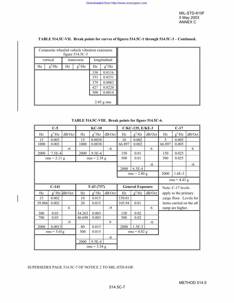
MIL-STD-810F5 May 2003ANNEX C
METHOD 514.5514.5C-7
TABLE 514.5C-VII. Break points for curves of figures 514.5C-1 through 514.5C-3 – Continued.
Composite wheeled vehicle vibration exposuresfigure 514.5C-3
vertical transverse longitudinal
Hz g2/Hz Hz g2/Hz Hz g2/Hz330 0.0116353 0.0231379 0.0083427 0.0220500 0.0014
2.05 g rms
TABLE 514.5C-VIII. Break points for figure 514.5C-6.
C-5 KC-10 C/KC-135, E/KE-3 C-17Hz g2/Hz dB/Oct Hz g2/Hz dB/Oct Hz g2/Hz dB/Oct Hz g2/Hz dB/Oct15 0.003 15 0.0038 10 0.002 5 0.005
1000 0.003 1000 0.0038 66.897 0.002 66.897 0.005-6 -6 6 6
2000 7.5E-4 2000 9.5E-4 150 0.01 150 0.025rms = 2.11 g rms = 2.38 g 500 0.01 500 0.025
-6 -62000 6.3E-4
rms = 2.80 g 2000 1.6E-3rms = 4.43 g
C-141 T-43 (737) General Exposure Note: C-17 levelsHz g2/Hz dB/Oct Hz g2/Hz dB/Oct Hz g2/Hz dB/Oct apply to the primary15 0.002 10 0.015 150.01 cargo floor. Levels for
39.086 0.002 20 0.015 105.94 0.01 items carried on the aft4 -9 6 ramp are higher.
300 0.03 34.263 0.003 150 0.02700 0.03 46.698 0.003 500 0.02
-9 9 -62000 0.0013 80 0.015 2000 1.3E-3
rms = 5.01g 500 0.015 rms = 4.02 g-6
2000 9.5E-4rms = 3.54 g
SUPERSEDES PAGE 514.5C-7 OF NOTICE 2 TO MIL-STD-810F.
Downloaded from http://www.everyspec.com

MIL-STD-810F30 August 2002ANNEX C
METHOD 514.5514.5C-8
3. FIGURES
0.00001
0.0001
0.001
0.01
0.1
1 10 100 1000
Frequency -Hz
Acc
eler
atio
n sp
ectra
l den
sity
-g2 /H
z
VerticalTransverseLongitudinal
Extend to lowest natural frequency
Curve break points are listed in table 514.5C-VII
FIGURE 514.5C-1. U. S. highway truck vibration exposure.
0.0001
0.001
0.01
0.1
1
1 10 100 1000
Frequency - Hz
Acc
eler
atio
n sp
ectra
l den
sity
- g2 /H
z
VerticalTransverseLongitudinal
Curve break points are listed in table 514.5.C-VII
FIGURE 514.5C-2. Composite two-wheeled trailer vibration exposure.
REPRINTED WITHOUT CHANGE.
Downloaded from http://www.everyspec.com

MIL-STD-810F5 May 2003ANNEX C
METHOD 514.5514.5C-9
0.0001
0.001
0.01
0.1
1
1 10 100 1000
Frequency - Hz
Acc
eler
atio
n sp
ectra
l den
sity
- g2 /H
z
VerticalTransverseLongitudinal
Curve break points are listed in table 514.5C-VII
FIGURE 514.5C-3. Composite wheeled vehicle vibration exposure.
1 10 100 1000
Frequency - Hz
Acc
eler
atio
n sp
ectra
l den
sity
- g2 /H
z
Note: Narrow bands represent swept regions.See reference "d" for detailed information.
FIGURE 514.5C-4. Tracked vehicle representative spectral shape.
SUPERSEDES PAGE 514.5C-9 OF NOTICE 2 TO MIL-STD-810F.
Downloaded from http://www.everyspec.com

MIL-STD-810F1 January 2000ANNEX C
METHOD 514.5514.5C-10
FIGURE 514.5C-5. Loose cargo test setup.
0.0001
0.001
0.01
0.1
1 10 100 1000 10000Frequency Hz
Acc
eler
atio
n Sp
ectra
l den
sity
- g2 /H
z
C-5KC-10C-17C/KC-135, E/KE-3C-141T-43 (737)General Exposure
Curve break point values are shown in Table 514.5C-VIII
FIGURE 514.5C-6. Jet aircraft cargo vibration exposure.
REPRINTED WITHOUT CHANGE.
Downloaded from http://www.everyspec.com

MIL-STD-810F5 May 2003
METHOD 516.5516.5-27
Step 4. Mount the test item in the fixture. Inspect and functionally test the item to document the pre-testcondition.
Step 5. Perform the shock test at the selected level and examine the recorded data to assure the test maximaxacceleration SRS is within tolerance.
Step 6. Visually examine and functionally test the materiel to determine if damage has occurred. If damage isfound or pre-established goals have been reached, go to Step 10.
Step 7. If it is required to determine the fragility of the test item in more than one axis then proceed to test theitem in the other axes (before changing the peak maximax acceleration SRS level).
Step 8. If the test item integrity is preserved, select the next predetermined peak maximax acceleration SRSlevel.
Step 9. Repeat steps 5 through 8 until the test objectives have been met.
Step 10. Document the results recording the peak maximax acceleration SRS to define the fragility level. If thetest item is damaged in one axis during test, then replace the test item with an identically configuredtest item and proceed in testing starting at Step 4.
4.5.4.4 Analysis of results.Refer to the guidance in Part One, paragraph 5.14, to assist in the evaluation of the test results. The outcome of asuccessful fragility test is one specified measurement level of test item failure to each test axis. Consider that if thetest item fails either functionally or structurally at the lowest level of testing and there is no provision for testing atlower levels, then the test item's fragility level is indeterminate.
4.5.5 Procedure IV - Transit Drop. The intent of this test is to determine the structural and functional integrity of the materiel to a transit drop in itstransit or combination case. Perform all tests with a quick release hook or drop tester. In general, there is noinstrumentation calibration for the test and measurement information is minimized, however, if measurements aremade, the maximax acceleration SRS and the pseudovelocity SRS will define the results of the test, along with themeasurement amplitude time history.
4.5.5.1 Controls. Test levels for this test are shown in table 516.5-VI. Test the item in the same configuration that is used in atransportation, handling or a combat situation. For test items under 45kg (100 pounds), the 26-drop requirement(table 516.5-VI) may be divided among up to five samples of the same test item in any combination. Toppling of theitem following impact will occur in the field and, therefore, toppling of the test item following its initial impactshould not be restrained as long as the test item does not leave the required drop surface. Levels for this test wereset by considering how materiel in the field might commonly be dropped. (For example, a light item might becarried by one man, chest high; thus it could drop 122 cm (48 inches).) Field data have shown that a typical pieceof man-portable materiel will be dropped from heights up to 122 cm an average of four to six times during its lifecycle. The 26-drop requirement exists to ensure each vulnerable position (faces, edges, and corners) of a typical testitem receives an impact. Conduct drops for equipment -5 up to 454 Kg (1000 pounds) and having its largestdimension less than 91 cm (36 inches) using a quick release hook, or drop tester. For the floor or barrier receivingthe impact use two-inch plywood backed by concrete. For equipment over 454 Kg, use a concrete floor or barrier.
4.5.5.2 Test tolerances.Ensure the test height of drop is within 2.5% of the height of drop as specified in table 516.5-VI.
SUPERSEDES PAGE 516.5-27 OF MIL-STD-810F.
Downloaded from http://www.everyspec.com

MIL-STD-810F5 May 2003
METHOD 516.5516.5-28
4.5.5.3 Procedure IV.Step 1. After performing a visual inspection and operational check for baseline data, install the test item in its
transit or combination case as prepared for field use (if measurement information is to be obtained,install and calibrate such instrumentation in this step.)
Step 2. From paragraph 4.5.5.1 and table 516.5-VI, determine the height of the drops to be performed, thenumber of drops per test item, and the drop surface.
Step 3. Perform the required drops using the apparatus and requirements of paragraph 4.5.5.1 and table 516.5-VI notes. Recommend visually and/or operationally checking the test item periodically during the droptest to simplify any follow-on failure evaluation that may be required.
Step 4. Document the impact point or surface for each drop and any obvious damage.
Step 5. Following completion of the required drops, visually examine the test item(s).
Step 6. Document the results.
Step 7. Conduct an operational checkout in accordance with the approved test plan.
Step 8. Document the results for comparison with data obtained in Step 1, above (if measurement informationwas obtained during the drop examine the time history traces and process them in this step according toprocedures outlined in the test plan).
4.5.5.4 Analysis of results. Refer to the guidance in Part One, paragraph 5.14, to assist in the evaluation of the test results. In general, analysisof results will consist of visual and operational comparisons for before test and after test. Measurementinstrumentation and subsequent processing of acceleration time history information can provide valuableinformation related to response characteristics of the test item and statistical variation in the shock environment.
4.5.6 Procedure V - Crash Hazard. The intent of this procedure is to disclose structural failures of materiel or mounts for materiel in air or groundvehicles that may present a hazard to personnel or other materiel if the materiel breaks loose from its mount duringor after a vehicle crash. The test in this procedure is intended to verify that materiel mounting and/or restrainingdevices will not fail, and that sub-elements are not ejected during crash situations. Attach the test item to its shockfixture by its in-service mounting or tiedowns.
4.5.6.1 Controls. Use figure 516.5-8 as the test spectrum for the axis of test with the effective shock duration, Te, between 15 and 23milliseconds for flight materiel, and between 8 and 13 milliseconds for ground materiel. If shock spectrum analysiscapabilities are not available, the classical terminal peak sawtooth pulse on figure 516.5-10 may be used as analternative to a complex transient waveform developed from the SRS on figure 516.5-8. Table 516.5-VII providesthe parameters for the terminal peak sawtooth pulse. An aircraft crash level of 40 g's is based on the assumptionthat, during a survivable crash, localized g levels can approach 40 g's. Ground transportation vehicles are designedwith a higher safety factor and, therefore, must sustain a much higher g level with correspondingly higher specifiedtest levels.
SUPERSEDES PAGE 516.5-28 OF MIL-STD-810F.
Downloaded from http://www.everyspec.com

MIL-STD-810F5 May 2003
METHOD 518518-1
METHOD 518
ACIDIC ATMOSPHERE
NOTE: Tailoring is essential. Select methods, procedures and parameter levels based on the tailoring processdescribed in Part One, paragraph 4.2.2, and Appendix C. Apply the general guidelines for laboratory test methodsdescribed in Part One, paragraph 5 of this standard.
1. SCOPE.
1.1 Purpose. Use the acidic atmosphere test to determine the resistance of materials and protective coatings to corrosiveatmospheres.
1.2 Application. Use this test method when the requirements documents state that the materiel is likely to be stored or operated inareas where acidic atmospheres exist, such as industrial areas or near the exhausts of any fuel-burning device.
1.3 Limitations.
This method is not a replacement for the salt fog method, nor is it suitable for evaluating the effects of hydrogensulfide that readily oxidizes in the test environment to form sulfur dioxide. Consult ASTM G85, “Standard Practicefor Modified Salt Spray (Fog) Testing” for information on introducing a sulfur dioxide environment. Caution:Although salt fog chambers are usually used for this test, introducing an acidic or sulfur dioxide atmosphere in a saltfog chamber may contaminate the chamber for future salt fog tests.
2. GUIDANCE/REQUIREMENTS.
2.1 Effects of the Environment. Acidic atmospheres are of increasing concern, especially for materiel in the vicinity of industrial areas or near theexhausts of fuel burning devices. Examples of problems that could occur as a result of acidic atmosphere exposureare as follows. The list is not intended to be all-inclusive, and some of the examples may overlap the categories. Reference a. provides further information.
a. Chemical attack of surface finishes and non-metallic materials. b. Corrosion of metals.c. Pitting of cement and optics.
2.2 Test Procedure. When an acidic atmosphere test is deemed necessary, the procedure included in this method is considered suitablefor most applications. The tailoring options are limited.
2.3 Sequence.a. General. See Part One, paragraph 5.5.b. Unique to this method. There are at least two philosophies related to test sequence. One approach is to
conserve test item life by applying what are perceived to be the least damaging environments first. Forthis approach, generally apply the acidic atmosphere test late in the test sequence. Another approach isto apply environments to maximize the likelihood of disclosing synergetic effects. For this approach,consider acidic atmosphere testing following dynamic tests, such as vibration and shock. Perform acidicatmosphere testing after any humidity or fungus testing, and before any sand and dust testing or other
SUPERSEDES PAGE 518-1 OF MIL-STD-810F.
Downloaded from http://www.everyspec.com

MIL-STD-810F5 May 2003
METHOD 518518-2
tests which damage protective coatings. Because this test is similar in severity to the salt fog test,recommend separate test items be used for each.- Sand and dust testing deposits may inhibit acid effects as well as abrade protective coatings;- Acid deposits may inhibit mold/fungal growth;- Residual deposits may accelerate chemical reactions during humidity testing.
2.4 Determine Test Levels and Conditions. Having selected this method and relevant procedures (based on the test item's requirements documents and thetailoring process), complete the tailoring process by identifying appropriate parameter levels and applicable testconditions and techniques for these procedures. Base these selections on the requirements documents, the LifeCycle Environmental Profile, Operational Environment Documentation (see Part One, figure 1-1), and informationprovided with this procedure. Consider the essential parameters for defining the acidic atmosphere test that includeexposure temperature, exposure time (duration), test item configuration, chemical composition of the testatmosphere, and concentration of the test solution.
2.4.1 Temperature severities. The test method and the exposure temperature used in this procedure are similar to that used in the salt fog test.
2.4.2 Test duration. Two severity levels are defined (reference b.). In view of the complexity of naturally occurring corrosion processes,no strict equivalencies with real exposure can be quoted. Use severity "a" below for simulating infrequent periodsof exposure, or for exposure in areas of much lower acidity. Use severity "b" below to represent approximately 10years natural exposure in a moist, highly industrial area, or a shorter period in close proximity to vehicle exhaustsystems, particularly ship funnel exhausts where the potential acidity is significantly higher.
a. Three 2-hour exposure periods with 22 hours storage after each.b. Four 2-hour exposure periods with 7 days storage after each.
2.4.3 Test item configuration. The configuration of the materiel is an important factor in how an acidic atmosphere affects it. Therefore, duringthe test use the anticipated configuration of the materiel during storage or use. As a minimum, consider thefollowing configurations:
a. In a shipping/storage container or transit case.b. Protected or unprotected.c. Deployed (realistically or with restraints, such as with openings that are normally covered).d. Modified with kits for special applications.
2.4.4 Chemical composition and concentration. For atomization, use a test solution containing 11.9 mg (6 :l) sulfuric acid (95-98%)/4 liters of solution and 8.8 mg(6 :l) nitric acid (68-71%)/4 liters solution in distilled or deionized water. This will produce a solution with a pH of4.17 that is representative of some of the worst rain pH’s recorded for rainfall in the eastern United States and otherheavily industrialized areas with acidic emissions. Reference c. provides information regarding the more commonchemical environmental contaminants together with some consequent likely forms of corrosion that material couldencounter.
WARNING: Strong acids are hazardous. The solution to be sprayed is harmful to people and clothing. Operatorscarrying out the test must take suitable precautions.
WARNING: Refer to the supplier’s Material Safety Data Sheet (MSDS) or equivalent for health hazard data.
SUPERSEDES PAGE 518-2 OF MIL-STD-810F.
Downloaded from http://www.everyspec.com

MIL-STD-810F5 May 2003
METHOD 518518-3
a. Do not enter the chamber during atomization and, before entry after exposure, purge the chamber withclean air to a level that will satisfy local safety requirements. Continue purging at intervals if necessaryto ensure the concentration of noxious fumes remains at a suitably low level.
b. Wear a suitable respirator and/or eye protection. Use rubber gloves to handle materiel.c. See paragraph 4.1b for hazardous waste disposal information.
2.4.5 Operational considerations. The test item will not normally be required to function during the test, but may be required to do so uponcompletion of the test, or on completion of a representative sequence of environmental tests.
3. INFORMATION REQUIRED.
3.1 Pretest. The following information is required to conduct acidic atmosphere tests adequately.
a. General. Information listed in Part One, paragraphs 5.7 and 5.9, and Appendix A, Task 405 of thisstandard.
b. Specific to this method.(1) Areas of the test item visually and functionally examined and an explanation of their inclusion or
exclusion.
(2) Whether the test is a demonstration of performance or survival.
(3) Whether the requirement is to demonstrate safety, safety and performance, or resistance to chemicalattack after the test.
(4) If functional performance is to be assessed, the phases of the test when the test item is to functionand be assessed, and the levels of performance required.
3.2 During Test. Collect the following information during conduct of the test:
a. General. Information listed in Part One, paragraph 5.10, and in Appendix A, Task 406 of this standard.b. Specific to this method.
(1) Record of chamber temperature versus time conditions.(2) Fallout quantities per unit of time (see paragraph 4.1g).(3) Fallout pH.
3.3 Post Test.The following post test information is required.
a. General. Information listed in Part One, paragraph 5.13, and in Appendix A, Task 406 of this standard.b. Specific to this method.
(1) Areas of the test item visually and functionally examined and an explanation of their inclusion orexclusion.
(2) Test variables:(a) Test solution pH.(b) Test solution fallout rate (ml/cm2/hr).
SUPERSEDES PAGE 518-3 OF MIL-STD-810F.
Downloaded from http://www.everyspec.com

MIL-STD-810F5 May 2003
METHOD 518518-4
(3) Results of examination for corrosion, electrical, and physical effects.
(4) Observations to aid in failure analysis.
4. TEST PROCESS.
4.1 Test Facility.a. For construction of the chamber, supporting racks, and atomization equipment use materials inert to the
acid solution being used, and that will not cause electrolytic corrosion with material with which it comesin contact.
b. Ensure the test chamber has a waste collection system so that all waste material can be tested prior todisposal. Dispose of any material determined to be hazardous waste in accordance with local, state, andfederal regulations.
c. Do not reuse acidic test solution drippings from the walls and ceilings of the chamber, and from the testitem. Vent the exposure chamber to prevent pressure buildup.
d. Use a chamber capable of maintaining temperatures in the exposure zone at 35 "2!C. Continuouslycontrol this temperature during the test. Do not use immersion heaters within the chamber exposure areafor the purpose of maintaining the temperature within the exposure zone.
e. Use an acid solution reservoir and dispenser made of material that is non-reactive with the acid solution,e.g., glass, hard rubber, or plastic. The reservoir provides a continuous supply to a tank normally (butnot necessarily) situated inside the test section in which the acid solution level is held reasonablyconstant. The atomizers are connected to this tank.
f. Use a chamber with a means for injecting the acid solution into the test chamber and with an input airhumidifier to minimize clogging of the nozzles. Use atomizers of such design and construction as toproduce a finely divided, wet, dense fog. Use atomizing nozzles and a piping system made of materialthat is non-reactive to the acid solution. Use a facility designed to provide the required atomizationdistribution and fallout.
g. Use a test setup that includes a minimum of 2 fallout collection receptacles. One is to be at theperimeter of the test item nearest to the nozzle, and the other also at the perimeter of the test item but atthe farthest point from the nozzle. If multiple nozzles are used, the same principles apply. Place thereceptacles so that they are not shielded by the test item and will not collect drops of solution from thetest item or other sources.
h. Constant air pressure for the continuous, uniform atomization of the acid solution using a compressedair supply, and produce a fallout such that each receptacle collects from 1 to 3 ml of solution per hourfor each 80 cm2 of horizontal collecting area (10 cm diameter).
4.2 Controls. a. Compressed air. Preheat the oil and dirt-free compressed air used to produce the atomized solution (to
offset the cooling effects of expansion to atmospheric pressure) and pre-humidify it such that thetemperature is 35 "2°C and the relative humidity is in excess of 85% at the nozzle (see table 518-I).
b. Preheating. Heat the acid solution to within "6°C of the test section temperature before injection intothe test section.
c. Test section air circulation. Use an air velocity in the test chambers that is minimal (essentially zero).
SUPERSEDES PAGE 518-4 OF MIL-STD-810F.
Downloaded from http://www.everyspec.com

MIL-STD-810F5 May 2003
METHOD 518518-5
TABLE 518-I. Temperature and pressure requirements for operation at 35!C.
Air Pressure (kPa) 83 96 110 124
Preheat temperature (°C)(before atomizing)
46 47 48 49
4.3 Test Interruptions.a. General. See Part One, paragraph 5.11 of this standard.
b. Specific to this method.
(1) Undertest interruption. If an unscheduled test interruption occurs that causes the test conditions toexceed allowable tolerances toward standard ambient conditions, give the test item a completevisual examination and develop a technical evaluation of the impact of the interruption on the testresults. Restart the test at the point of interruption and restabilize the test item at the test conditions.
(2) Overtest interruption. If an unscheduled test interruption occurs that causes the test conditions toexceed allowable tolerances away from standard ambient conditions, stabilize the test conditions towithin tolerances and hold them at that level until a complete visual examination and technicalevaluation can be made to determine the impact of the interruption on test results. If the visualexamination or technical evaluation results in a conclusion that the test interruption did notadversely affect the final test results, or if the effects of the interruption can be nullified withconfidence, restabilize the pre-interruption conditions and continue the test from the point where thetest tolerances were exceeded.
4.4 Procedure. The following test procedure provides a basis for assessing the suitability of the test item in an acidic atmosphereenvironment, and has limited tailorability.
4.4.1 Pretest information. See General Guidance and Information, paragraphs 5 and 6.1.
4.4.2 Preparation for test. a. Prepare a test solution as specified in paragraph 2.4.4. NOTE: MAKE THE SOLUTION BY ADDING
ACID TO WATER, NOT VICE VERSA.
WARNING: Strong acids are hazardous. The solution to be sprayed is harmful to people and clothing. Operatorscarrying out the test must take suitable precautions.
WARNING: Refer to the supplier’s Material Safety Data Sheet (MSDS) or equivalent for health hazard data.
(1) Do not enter the chamber during atomization. Before entry after atomization, purge the chamberwith clean air to a level that will satisfy local safety requirements. Continue purging at intervals ifnecessary to ensure the concentration of noxious fumes remains at a suitably low level.
(2) Wear a suitable respirator and/or eye protection. Use rubber gloves to handle materiel.
b. Chamber performance verification: Immediately before the test and with the exposure chamber empty,adjust all test parameters to those levels required for the test. Maintain these conditions for at least one24-hour period (or until proper operation and fallout collection can be verified). With the exception offallout rate, continuously monitor all test parameters to verify that the test chamber is operating properly.
SUPERSEDES PAGE 518-5 OF MIL-STD-810F.
Downloaded from http://www.everyspec.com

MIL-STD-810F5 May 2003
METHOD 518518-6
c. Conduct an operational checkout in accordance with the test plan and record the results for compliancewith Part One, paragraph 5.9. Handle the test item as little as possible, particularly on the significantsurfaces, and prepare it for test immediately before exposure. Unless otherwise specified, use test itemsfree of surface contamination such as oil, grease, or dirt, which could cause dewetting. Do not includethe use of corrosive solvents, solvents that deposit either corrosive or protective films, or abrasives otherthan pure magnesium oxide in the cleaning methods.
4.4.3 Acidic atmosphere test procedure.Step 1. With the test item installed in the test chamber in its storage configuration (or as otherwise specified in
the requirements documents), adjust the test chamber temperature to 35°C and temperature conditionthe test item for at least 2 hours before introducing the acid solution.
Step 2. Expose the test item to one of the two following severities as specified in the test plan. (See paragraph2.4.2.)a. Four 2-hour atomization periods with 7 days storage after each.b. Three 2-hour atomization periods with 22 hours storage after each.
Step 3. At the completion of Step 2, stabilize the test item at standard ambient conditions.Step 4. Using appropriate protective clothing, visually examine the test item to the extent practical.Step 5. If required, place the test item in an operational configuration and conduct an operational check of the
test item.Step 6. If required, test items may be cleaned by rinsing with a dilute sodium bicarbonate solution (to
neutralize any acidic residue), followed by distilled/deionized water, and dried by the application ofheat (up to 55°C), where this is acceptable, or by other means. Collect the rinse water and check it forhazardous substances prior to disposal (see paragraph 4.1b also).
Step 7. At the end of this test, and in conformity with the requirements documents, examine the test item forcorrosion and deterioration of parts, finishes, materials, and components.
5. ANALYSIS OF RESULTS. In addition to the guidance provided in Part One, paragraphs 5.14 and 5.17, the following information is provided toassist in the evaluation of the test results. Analyze any corrosion for its immediate effect on the satisfactoryfunctioning of the test item. Satisfactory operation following this test is not the sole criterion for pass/fail.
6. REFERENCE/RELATED DOCUMENTS.a. DEF STAN 00-50, Guide to Chemical Environmental Contaminants and Corrosion Affecting the
Design of Military Materiel. (UK)b. IEC 68-2-52, 1966, Test Kb, Salt Mist, Cyclic, NaCl solution.c. Acid Deposition in the United Kingdom, Warren Spring Laboratory, ISBN 085624 323X. (UK)d. NATO STANAG 4370, Environmental Testing.e. NATO Allied Environmental Conditions and Test Publication (AECTP) 300, Climatic
Environmental Tests, Method 319, “Acidic Atmosphere.”
SUPERSEDES PAGE 518-6 OF MIL-STD-810F.
Downloaded from http://www.everyspec.com

MIL-STD-810F5 May 2003
METHOD 520.2520.2-11
4. TEST PROCESS
4.1 Test facility.Use a facility that can provide the required combination of environmental elements. See the guidance for thefacilities for the individual element tests, i.e., methods 500.4, 501.4, 502.4, 507.4, and 514.5. Ensure the facilitysatisfies the requirements of Part One, paragraph 5.
4.2 Controls. Ensure calibration and test tolerance procedures are consistent with the guidance provided in Part One, paragraphs5.3.2 and 5.2, respectively.
4.3 Test interruption.a. General. See Part One, paragraph 5.11 of this standard.b. Specific to this method.
(1) Undertest interruption. Refer to the interruption guidance for the individual test elements; i.e.,temperature, humidity, low pressure, and vibration.
(2) Overtest interruption. Refer to the interruption guidance for the individual test elements; i.e.,temperature, humidity, low pressure, and vibration.
4.4 Data analysis.Detailed data analysis for verification of the input to the test item and the response monitoring of the test item are tobe in accordance with the test plan.
4.5 Test execution.The following steps, alone or in combination, provide the basis for collecting necessary information concerning thetest item in a combined environment of vibration, temperature, humidity, and altitude. Begin with the firstprocedure specified in the test plan.
4.5.1 Preparation for test
4.5.1.1 Preliminary steps. Before starting the test, review pretest information in the currently approved test plan to determine test details (e.g.,procedures, item configuration, cycles, durations, parameter levels for storage/operation, etc.). (See paragraph 3.1,above.)
4.5.1.2 Qualification test cycle. (Figure 520.2A-3.)Step 1. Ramp to Cold/Dry - With the test item non-operating, ramp the chamber temperature from room
ambient conditions down to the extreme low operating temperature at 5!C/minute or at a maximumrate provided by the test chamber.
Step 2. Cold/Dry Soak - Allow the test item to soak at this temperature until it has reached thermalstabilization or for 4 hours (whichever is greater). If vibration is to be performed during this step,derive it from a low altitude, high Mach flight condition (combined temperature/vibration may beperformed separately). Ground vehicles would use severe road/field vibration levels.
Step 3. Cold/Dry Warm-Up - Operate the test item at its minimum operating voltage. If supplemental coolingis supplied during this step, tailor cooling parameters for minimum heat removal (e.g., minimumtemperature and minimum flow for air cooling at or above the minimum operating temperature).Maintain this condition for the minimum specified warm-up period.
SUPERSEDES PAGE 520.2-11 OF NOTICE 2 TO MIL-STD-810F.
Downloaded from http://www.everyspec.com

MIL-STD-810F1 January 2000
METHOD 520.2520.2-12
Step 4. Cold/Dry Performance Check - Do a performance check immediately following Step 3 to verify thetest item operates as required.
Step 5. Ramp to Cold/Dry Altitude - With the test item operating, ramp the chamber from the site pressure tothe maximum cruise altitude (use the formulas on figure 520.2A-5 to derive pressure from altitude). Perform the pressure ramp at the maximum facility rate, not to exceed the predicted platform rate. Notapplicable to ground vehicles.
Step 6. Cold/Dry Altitude - Maintain the maximum cruise altitude for 30 minutes. If vibration is to beperformed during this step, derive it from a high altitude, high Mach flight condition. Not applicable toground vehicles.
Step 7. Ramp to Warm/Moist - Ramp the chamber conditions from Step 6 and uncontrolled humidity to 32!C(90!F) and site pressure and 95% relative humidity (RH). Perform this temperature/humidity/altituderamp at the maximum facility rate, not to exceed the predicted platform rate. This step simulates aquick descent from a high altitude and allows an altitude chamber to simulate a high altitude descent toa hot/humid day landing site. Not applicable to ground vehicles.
Step 8. Warm/Moist Dwell - Maintain 32!C, site pressure and 95% relative humidity for 30 minutes. Ifvibration is to be performed during this step, derive it from a low altitude, high Mach flight condition. Ground vehicles use an aggregate vibration schedule based on various road conditions.
Step 9. Ramp to Hot/Dry - Ramp the chamber temperature to the maximum operating temperature and thechamber humidity to less than 30% RH. Operate the test item at its maximum operating voltage. Atthe same time, supply supplemental cooling at the worst case thermal conditions (e.g., maximumtemperature and minimum flow for air-cooling). Perform this temperature/humidity ramp at themaximum facility rate, not to exceed the predicted platform rate.
Step 10. Hot/Dry Soak - Allow the test item to soak at the maximum operating temperature until it has reachedthermal stabilization or 2 hours (whichever is greater). If vibration is to be performed during this step,derive the vibration levels from the maximum of take-off/ascent or low altitude/high Mach (ifappropriate). Ground vehicles use aggregate off-road vibration levels.
Step 11. Hot/Dry Performance Check - Operate the test item and record data for comparison with pretest data.Step 12. Ramp to Hot/Dry Altitude - Ramp the chamber from site pressure to the maximum cruise altitude (use
the formulas on figure 520.2A-5 to derive pressure from altitude). Perform this pressure ramp at themaximum facility rate, not to exceed the predicted platform rate. Not applicable to ground vehicles.
Step 13. Hot/Dry Altitude - With the test item operating, maintain the maximum operating temperature andmaximum cruise altitude until the test item has reached thermal stabilization or 4 hours (whichever isgreater). If vibration is to be performed during this step, derive it from a high (or ultra-high ifapplicable) altitude, high Mach flight condition. Not applicable to ground vehicles.
Step 14. Hot/Dry Altitude Performance Check - Do a performance check to verify that the test item operates asrequired.
Step 15. Ramp to Room Ambient - Ramp the chamber from the maximum operating temperature and maximumcruise altitude to room ambient temperature, site pressure and uncontrolled humidity. Perform thistemperature/pressure ramp at the maximum facility rate, not to exceed the predicted platform rate. Return the test item to a non-operating condition and discontinue the supplemental cooling at theconclusion of the ramp.
Step 16. Repeat the cycle (Steps 1-15) as necessary to meet the test plan duration requirements or 10 cycles,whichever is greater.
4.5.1.3 Test development schedule.Utilized for each Procedure.
Step 1. Identify the platform missions and test materiel location.Step 2. Identify the mission profiles.Step 3. Select the top 80% of potential mission profile. (Table 520.2-I) (Procedure III only.)Step 4. Select most severe potential mission profile. (Exception: short term and transient events, e.g., gunfire,
crash shock, etc.) (Procedures I and III).Step 5. Identify the vibration levels by mission profile.
REPRINTED WITHOUT CHANGE.
Downloaded from http://www.everyspec.com

MIL-STD-810F5 May 2003ANNEX A
METHOD 520.2520.2A-3
FIGURE 520.2A-3. Qualification test cycle.
SUPERSEDES PAGE 520.2A-3 OF NOTICE 2 TO MIL-STD-810F.
Extreme Low Oper.
Downloaded from http://www.everyspec.com

MIL-STD-810F1 January 2000ANNEX A
METHOD 520.2520.2A-4
REPRINTED WITHOUT CHANGE.
Downloaded from http://www.everyspec.com