NOTICE OF CHANGE INCH-POUND The documentation...
27
1 MIL-STD-883E NOTICE 3 5 November 1999 DEPARTMENT OF DEFENSE TEST METHOD STANDARD MICROCIRCUITS TO ALL HOLDERS OF MIL-STD-883E: 1. THE FOLLOWING TEST METHODS OF MIL-STD-883E HAVE BEEN REVISED AND SUPERSEDE THE TEST METHODS LISTED: NEW METHOD DATE SUPERSEDED METHOD DATE 3023.1 5 November 1999 3023 19 August 1994 2. THE FOLLOWING PAGES OF MIL-STD-883E HAVE BEEN REVISED AND SUPERSEDE THE PAGES LISTED: METHOD NEW PAGE DATE SUPERSEDED PAGE DATE --- iii 31 December 1996 iii REPRINTED WITHOUT CHANGE --- iv 24 August 1998 iv REPRINTED WITHOUT CHANGE --- v 5 November 1999 v 31 December 1996 --- vi 31 December 1996 vi REPRINTED WITHOUT CHANGE 2009.9 5 19 August 1994 5 REPRINTED WITHOUT CHANGE 6 5 November 1999 6 19 August 1994 2020.7 1 5 November 1999 1 22 March 1989 2 5 November 1999 2 22 March 1989 2032.1 5 5 November 1999 3 1 June 1993 6 5 November 1999 4 1 June 1993 7 1 June 1993 7 REPRINTED WITHOUT CHANGE 8 5 November 1999 8 1 June 1993 13 5 November 1999 13 REPRINTED WITHOUT CHANGE 13a 5 November 1999 13a 1 June 1993 31 5 November 1999 31 1 June 1993 32 5 November 1999 32 1 June 1993 44a 5 November 1999 44a 1 June 1993 57 1 June 1993 57 REPRINTED WITHOUT CHANGE 58 5 November 1999 58 1 June 1993 5011.4 7 5 November 1999 7 31 October 1995 8 31 October 1995 8 REPRINTED WITHOUT CHANGE AMSC N/A FSC 5962 DISTRIBUTION STATEMENT A. Approved for public release; distribution is unlimited. INCH-POUND NOTICE OF CHANGE The documentation and process measures necessary to comply with this notice shall be completed by 5 April 2000. Downloaded from http://www.everyspec.com
Transcript of NOTICE OF CHANGE INCH-POUND The documentation...

1
MIL-STD-883ENOTICE 35 November 1999
DEPARTMENT OF DEFENSE
TEST METHOD STANDARDMICROCIRCUITS
TO ALL HOLDERS OF MIL-STD-883E:
1. THE FOLLOWING TEST METHODS OF MIL-STD-883E HAVE BEEN REVISED AND SUPERSEDE THE TESTMETHODS LISTED:
NEW METHOD DATE SUPERSEDED METHOD DATE
3023.1 5 November 1999 3023 19 August 1994
2. THE FOLLOWING PAGES OF MIL-STD-883E HAVE BEEN REVISED AND SUPERSEDE THE PAGES LISTED:
METHOD NEW PAGE DATE SUPERSEDED PAGE DATE
--- iii 31 December 1996 iii REPRINTED WITHOUT CHANGE --- iv 24 August 1998 iv REPRINTED WITHOUT CHANGE --- v 5 November 1999 v 31 December 1996 --- vi 31 December 1996 vi REPRINTED WITHOUT CHANGE2009.9 5 19 August 1994 5 REPRINTED WITHOUT CHANGE
6 5 November 1999 6 19 August 19942020.7 1 5 November 1999 1 22 March 1989
2 5 November 1999 2 22 March 19892032.1 5 5 November 1999 3 1 June 1993
6 5 November 1999 4 1 June 1993 7 1 June 1993 7 REPRINTED WITHOUT CHANGE 8 5 November 1999 8 1 June 1993 13 5 November 1999 13 REPRINTED WITHOUT CHANGE 13a 5 November 1999 13a 1 June 1993 31 5 November 1999 31 1 June 1993 32 5 November 1999 32 1 June 1993 44a 5 November 1999 44a 1 June 1993 57 1 June 1993 57 REPRINTED WITHOUT CHANGE 58 5 November 1999 58 1 June 1993
5011.4 7 5 November 1999 7 31 October 1995 8 31 October 1995 8 REPRINTED WITHOUT CHANGE
AMSC N/A FSC 5962DISTRIBUTION STATEMENT A. Approved for public release; distribution is unlimited.
INCH-POUND
NOTICE OFCHANGE
The documentation and process measures necessary tocomply with this notice shall be completed by 5 April 2000.
Downloaded from http://www.everyspec.com
MIL-STD-883ENOTICE 3
2
3. RETAIN THIS NOTICE AND INSERT BEFORE TABLE OF CONTENTS.
4. Holders of MIL-STD-883E will verify that page changes, additions, and corrections indicated above have beenentered. This notice page will be retained as a check sheet. This issuance, together with appended pages, is aseparate publication. Each notice is to be retained by stocking points until the military standard is completelyrevised or canceled.
NOTE: The margins of this notice are marked with asterisks to indicate where changes (additions, modifications,corrections, deletions) from the previous notice were made. This was done as a convenience only and theGovernment assumes no liability whatsoever for any inaccuracies in these notations. Bidders and contractors arecautioned to evaluate the requirements of this document based on the entire content irrespective of the marginalnotations and relationship to the last previous notice.
CONCLUDING MATERIAL
Custodians: Preparing activity:Army - CR DLA - CCNavy - ECAir Force - 11NASA-NADLA - CC
Review activities (Project 5962-1855)Army - AR, MI, SMNavy - OS, SH, TD, AS, CG, MCAir Force - 19, 99
Downloaded from http://www.everyspec.com

MIL-STD-883ENOTICE 3
iii
CONTENTS
PARAGRAPH Page
1. SCOPE ...................................................................................................................................... 11.1 Purpose.................................................................................................................................... 11.2 Intended use of or reference to MIL-STD-883 .......................................................................... 1
2. APPLICABLE DOCUMENTS ..................................................................................................... 32.1 General .................................................................................................................................... 32.2 Government documents ........................................................................................................... 32.3 Non-Government publications .................................................................................................. 42.4 Order of precedence ................................................................................................................ 5
3. ABBREVIATIONS, SYMBOLS, AND DEFINITIONS .................................................................. 63.1 Abbreviations, symbols, and definitions ................................................................................... 6
4. GENERAL REQUIREMENTS .................................................................................................... 84.1 Numbering system ................................................................................................................... 84.2 Test results .............................................................................................................................. 94.3 Test sample disposition............................................................................................................ 94.4 Orientation ............................................................................................................................... 94.5 Test conditions.........................................................................................................................124.6 General precautions.................................................................................................................14
5. DETAIL REQUIREMENTS.........................................................................................................15
6. NOTES.......................................................................................................................................16
FIGURES
FIGURE
1. Orientation of noncylindrical microelectronic devices to direction of applied force............................................................................................................10
2. Orientation of cylindrical microelectronic device to direction of applied force............................................................................................................11
REPRINTED WITHOUT CHANGE
Downloaded from http://www.everyspec.com
MIL-STD-883ENOTICE 3
iv
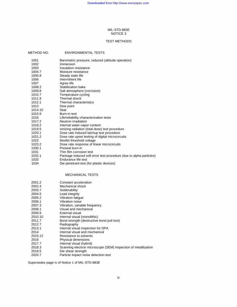
TEST METHODS
METHOD NO. ENVIRONMENTAL TESTS
1001 Barometric pressure, reduced (altitude operation)1002 Immersion1003 Insulation resistance1004.7 Moisture resistance1005.8 Steady state life1006 Intermittent life1007 Agree life1008.2 Stabilization bake1009.8 Salt atmosphere (corrosion)1010.7 Temperature cycling1011.9 Thermal shock1012.1 Thermal characteristics1013 Dew point1014.10 Seal1015.9 Burn-in test1016 Life/reliability characterization tests1017.2 Neutron irradiation1018.2 Internal water-vapor content1019.5 Ionizing radiation (total dose) test procedure1020.1 Dose rate induced latchup test procedure1021.2 Dose rate upset testing of digital microcircuits1022 Mosfet threshold voltage1023.2 Dose rate response of linear microcircuits1030.1 Preseal burn-in1031 Thin film corrosion test1032.1 Package induced soft error test procedure (due to alpha particles)1033 Endurance life test1034 Die penetrant test (for plastic devices)
MECHANICAL TESTS
2001.2 Constant acceleration2002.4 Mechanical shock2003.7 Solderability2004.5 Lead integrity2005.2 Vibration fatigue2006.1 Vibration noise2007.3 Vibration, variable frequency2008.1 Visual and mechanical2009.9 External visual2010.10 Internal visual (monolithic)2011.7 Bond strength (destructive bond pull test)2012.7 Radiography2013.1 Internal visual inspection for DPA2014 Internal visual and mechanical2015.12 Resistance to solvents2016 Physical dimensions2017.7 Internal visual (hybrid)2018.3 Scanning electron microscope (SEM) inspection of metallization2019.5 Die shear strength2020.7 Particle impact noise detection test
Supersedes page iv of Notice 1 of MIL-STD-883E
Downloaded from http://www.everyspec.com

MIL-STD-883ENOTICE 3
v
TEST METHODS
METHOD NO. MECHANICAL TESTS
2021.3 Glassivation layer integrity2022.2 Wetting balance solderability2023.5 Nondestructive bond pull2024.2 Lid torque for glass-frit-sealed packages2025.4 Adhesion of lead finish2026 Random vibration2027.2 Substrate attach strength2028.4 Pin grid package destructive lead pull test2029 Ceramic chip carrier bond strength2030 Ultrasonic inspection of die attach2031.1 Flip chip pull-off test2032.1 Visual inspection of passive elements2035 Ultrasonic inspection of TAB bonds
ELECTRICAL TESTS (DIGITAL)
3001.1 Drive source, dynamic3002.1 Load conditions3003.1 Delay measurements3004.1 Transition time measurements3005.1 Power supply current3006.1 High level output voltage3007.1 Low level output voltage3008.1 Breakdown voltage, input or output3009.1 Input current, low level3010.1 Input current, high level3011.1 Output short circuit current3012.1 Terminal capacitance3013.1 Noise margin measurements for digital microelectronic devices3014 Functional testing3015.7 Electrostatic discharge sensitivity classification3016 Activation time verification3017 Microelectronics package digital signal transmission3018 Crosstalk measurements for digital microelectronic device packages3019.1 Ground and power supply impedance measurements for digital microelectronics device packages3020 High impedance (off-state) low-level output leakage current3021 High impedance (off-state) high-level output leakage current3022 Input clamp voltage
* 3023.1 Static latch-up measurements for digital CMOS microelectronic devices3024 Simultaneous switching noise measurements for digital microelectronic devices
ELECTRICAL TESTS (LINEAR)
4001.1 Input offset voltage and current and bias current4002.1 Phase margin and slew rate measurements4003.1 Common mode input voltage range
Common mode rejection ratioSupply voltage rejection ratio
4004.1 Open loop performance4005.1 Output performance4006.1 Power gain and noise figure4007 Automatic gain control range
Supersedes page v of MIL-STD-883E
Downloaded from http://www.everyspec.com

MIL-STD-883ENOTICE 3
vi
TEST METHODS
METHOD NO. TEST PROCEDURES
5001 Parameter mean value control5002.1 Parameter distribution control5003 Failure analysis procedures for microcircuits5004.10 Screening procedures5005.13 Qualification and quality conformance procedures5006 Limit testing5007.6 Wafer lot acceptance5008.8 Test procedures for hybrid and multichip microcircuits5009.1 Destructive physical analysis5010.3 Test procedures for custom monolithic microcircuits5011.4 Evaluation and acceptance procedures for polymeric adhesives.5012.1 Fault coverage measurement for digital microcircuits.5013 Wafer fabrication control and wafer acceptance procedures for processed GaAs wafers.
REPRINTED WITHOUT CHANGE
Downloaded from http://www.everyspec.com

MIL-STD-883ENOTICE 3
METHOD 2009.919 August 1994
5
c. Radial cracks that exhibit the following:
1. Cracks that do not originate at the lead (see figures 2009-5a and 2009-5b).
2. Three or more cracks that extend beyond the midpoints of distance from the lead to the case (see figure2009-5c).
3. Two cracks that extend beyond the midpoint of the distance from the lead to the case and that lie within the samequadrant (see figure 2009-5d).
FIGURE 2009-5. Radial Cracks.
d. Any chip-out that penetrates the sealing glass deeper than the glass meniscus plane. The glass meniscus isdefined as that area of glass that wicks up the lead or terminal. Exposed base metal as a result of meniscus chipouts is acceptable, provided that the exposed area is no deeper than 0.010 inch (see figure 2009-6).
FIGURE 2009-6. Chip-outs.
REPRINTED WITHOUT CHANGE
Downloaded from http://www.everyspec.com

MIL-STD-883ENOTICE 3
METHOD 2009.919 August 1994
6
FIGURE 2009-7a. Surface bubbles. FIGURE 2009-7b. Subsurface bubbles.
e. Surface bubbles that exceed the following:
* 1. Open bubbles in the glass seal that exceed 5 mils in diameter (see Figure 2009-7a). For packages with a glass-filled header (i.e., TO-5), open bubbles that exceed 10 mils diameter, or an open bubble that exceeds 5 milsdiameter situated closer than 10 mils to a lead.
2. Open bubbles in strings or clusters that exceed 2/3 of the distance between the lead and the package wall.
f. Subsurface bubbles that exceed the following:
1. Large bubbles or voids that exceed 1/3 of the glass sealing area (see Figure 2009-8a).
2. Single bubble or void that is larger than 2/3 of the distance between the lead and the package wall at the site ofinclusion (see Figure 2009-7b and 2009-8b).
3. Two bubbles in a line totaling more than 2/3 distance from pin to case (see Figure 2009-8c).
4. Interconnecting bubbles greater than 2/3 the distance between pin and case (see Figure 2009-8d).
FIGURE 2009-8. Subsurface bubbles.
g. Reentrant seals that exhibit non-uniform wicking (i.e., negative meniscus) at the lead and/or body interface (see
Supersedes page 6 of MIL-STD-883E Notice 2
Downloaded from http://www.everyspec.com

MIL-STD-883ENOTICE 3
METHOD 2020.722 March 1989
1
METHOD 2020.7
PARTICLE IMPACT NOISE DETECTION TEST
1. PURPOSE. The purpose of this test is to detect loose particles inside a device cavity. The test provides anondestructive means of identifying those devices containing particles of sufficient mass that, upon impact with the case,excite the transducer.
2. APPARATUS. The equipment required for the particle impact noise detection (PIND) test shall consist of the following(or equivalent):
a. A threshold detector to detect particle noise voltage exceeding a preset threshold of the absolute value of 20 ±1millivolt peak reference to system ground.
b. A vibration shaker and driver assembly capable of providing essentially sinusoidal motion to the device under test(DUT) at:
(1) Condition A: 20 g peak at 40 to 250 Hz.
(2) Condition B: 10 g peak at 60 Hz minimum.
c. PIND transducer, calibrated to a peak sensitivity of -77.5 ±3 dB in regards to one volt per microbar at a point withinthe frequency of 150 to 160 kHz.
d. A sensitivity test unit (STU) (see figure 2020-1) for periodic assessment of the PIND system performance. TheSTU shall consist of a transducer with the same tolerances as the PIND transducer and a circuit to excite thetransducer with a 250 microvolt ±20 percent pulse. The STU shall produce a pulse of about 20 mV peak on theoscilloscope when the transducer is coupled to the PIND transducer with attachment medium.
e. PIND electronics, consisting of an amplifier with a gain of 60 ±2 dB centered at the frequency of peak sensitivity ofthe PIND transducer. The noise at the output of the amplifier shall not exceed 10 mV peak.
f. Attachment medium. The attachment medium used to attach the DUT to the PIND transducer shall be the sameattachment medium as used for the STU test.
g. Shock mechanism or tool capable of imparting shock pulses of 1,000 ±200 g peak to the DUT. The duration of themain shock shall not exceed 100 µs. If an integral co-test shock system is used the shaker vibration may beinterrupted or perturbed for period of time not to exceed 250 ms from initiation of the last shock pulse in thesequence. The co-test duration shall be measured at the 50 ±5 percent point.
3. PROCEDURES.
* 3.1 Test equipment setup. Shaker drive frequency and amplitude shall be adjusted to the specified conditions based oncavity size of the DUT (for condition A, see table I herein). The shock pulse shall be adjusted to provide 1,000 ±200 g peakto the DUT.
3.2 Test equipment checkout. The test equipment checkout shall be performed a minimum of one time per operationshift. Failure of the system to meet checkout requirements shall require retest of all devices tested subsequent to the lastsuccessful system checkout.
3.2.1 Shaker drive system checkout. The drive system shall achieve the shaker frequency and the shaker amplitudespecified. The drive system shall be calibrated so that the frequency settings are within ±8 percent and the amplitudevibration setting are within ±10 percent of the nominal values. If a visual displacement monitor is affixed to the transducer, itmay be used for amplitudes between 0.04 and 0.12 inch (1.02 and 3.05 mm). An accelerometer may be used over theentire range of amplitudes and shall be used below amplitudes of 0.040 inch (1.02 mm).
Supersedes page 1 of MIL-STD-883E
Downloaded from http://www.everyspec.com

MIL-STD-883ENOTICE 3
METHOD 2020.722 March 1989
2
3.2.2 Detection system checkout. With the shaker deenergized, the STU transducer shall be mounted face-to-face andcoaxial with the PIND transducer using the attachment medium used for testing the devices. The STU shall be activatedseveral times to verify low level signal pulse visual and threshold detection on the oscilloscope. Not every application of th eSTU will produce the required amplitude. All pulses which are greater than 20 mV shall activate the detector.
3.2.3 System noise verification. System noise will appear as a fairly constant band and must not exceed 20 millivoltspeak to peak when observed for a period of 30 to 60 seconds.
3.3 Test sequence. The following sequence of operations (a through i) constitute one test cycle or run.
a. 3 pre-test shocks.
b. Vibration 3 ±1 seconds.
c. 3 co-test shocks.
d. Vibration 3 ±1 seconds.
e. 3 co-test shocks.
f. Vibration 3 ±1 seconds.
g. 3 co-test shocks.
h. Vibration 3 ±1 seconds.
i. Accept or reject.
* 3.3.1 Mounting requirements. Special precautions (e.g., in mounting, grounding of DUT leads, or grounding of testoperator) shall be taken as necessary to prevent electrostatic damage to the DUT. Batch testing is prohibited.
Most part types will mount directly to the transducer via the attachment medium. Parts shall be mounted with thelargest flat surface against the transducer at the center or axis of the transducer for maximum sensitivity. Where morethan one large surface exists, the one that is the thinnest in section or has the most uniform thickness shall bemounted toward the transducer, e.g., flat packs are mounted top down against the transducer. Small axial-lead, rightcircular cylindrical parts are mounted with their axis horizontal and the side of the cylinder against the transducer.Parts with unusual shapes may require special fixtures. Such fixtures shall have the following properties:
(1) Low mass.
(2) High acoustic transmission (aluminum alloy 7075 works well).
(3) Full transducer surface contact, especially at the center.
(4) Maximum practical surface contact with test part.
(5) No moving parts.
(6) Suitable for attachment medium mounting.
Supersedes page 2 of MIL-STD-883E
Downloaded from http://www.everyspec.com

MIL-STD-883ENOTICE 3
METHOD 2032.11 June 1993
5
(34) Resistor ladder rung is that portion of a resistor ladder structure intended to be laser trimmed to result in anincremental change in resistance.
(35) Resistor loop is a resistor structure resembling a loop in appearance that can be trimmed. A coarse loopstructure is one in which trimming results in a large resistance change (one that can cause an out-of-tolerance condition to occur). A fine loop structure is one in which trimming results in a small resistancechange (one that cannot cause an out-of-tolerance condition to occur).
(36) Resistor material, self passivating is one on which a conformal insulating layer can be thermally grown (suchas tantalum nitride on which tantalum pentoxide is grown).
(37) Scorching is discoloration of laser trimmed thin film resistor material without alteration of its physical form.
(38) Scratch, metallization is any tearing defect, including probe marks, in the surface of the metallization. A maron the metallization surface is not considered to be a scratch.
(39) Scratch, resistor is any tearing defect in the resistor film. A mar on the resistor surface is not considered tobe a scratch.
(40) Sidebar is that portion of a resistor ladder structure to which rungs are attached. Sidebars are not intendedto be laser trimmed.
(41) Substrate is the supporting structural material into or upon which, or both, functional circuits are formed.
(42) Surface Acoustic Wave (SAW) element is a planar element fabricated typically using thin film manufacturingtechniques on various substrate materials. Size varies as a function of frequency and design featuresinclude interdigitated fingers.
(43) Terminal is a metal area used to provide an electrical access point to functional circuitry.
(44) Thick film is conductive, resistive or dielectric material screen printed onto a substrate and fired attemperature to fuse into its final form.
(45) Thin film is conductive, resistive or dielectric material, usually less than 50,000Å in thickness, that isdeposited onto a substrate by vacuum evaporation, sputtering, or other means.
(46) Underlying material is any layer of material below the top-layer metallization. This includes metallization,resistor, passivation or insulating layers, or the substrate itself.
* (47) Via is an opening in the insulating material in which a vertical conductive electrical connection from onemetallization layer to another is made.
(48) Vitrification is conversion into glass or a glassy substance by heat and fusion.
(49) Void, metallization is any missing metallization where the underlying material is visible (exposed). Voidstypically are caused by photolithographic, screen, or mask related defects, not by scratches.
(50) Void, resistor is any missing resistor material where the underlying material is visible (exposed). Voidstypically are caused by photolithographic, screen, or mask related defects, not by scratches.
Supersedes page 5 of MIL-STD-883E
Downloaded from http://www.everyspec.com

MIL-STD-883ENOTICE 3
METHOD 2032.11 June 1993
6
(51) Wraparound conductor is one which extends around the edge of the substrate by design.
(52) Coupling (air) bridge is a raised layer of metallization used for interconnection that is isolated from thesurface of the element by an air gap or other insulating material.
(53) Pit is a depression produced in a substrate surface typically by nonuniform deposition of metallization or bynonuniform processing such as excessively powered laser trim pulses.
(54) Substrate, hard is the inorganic, rigid material into or upon which or both, functional circuits are formed.Typical materials are alumina and silicon.
(55) Blister, metallization is a hollow bump that can be flattened.
(56) Nodule, metallization is a solid bump that cannot be flattened.
* (57) Substrate plug via is a cylinder-like volume in the substrate material filled with conductive material whichmakes electrical connection from contact areas on the top surface to the back surface of the substrate.
3.1 Thin film element inspection. Inspection for visual defects described in this section shall be conducted on each planarthin film passive element. The "high magnification" inspection shall be within the range of 100X to 200X for both class H andclass K. The "low magnification" inspection shall be within the range of 30X to 60X for both class H and class K. Wheninspection is performed prior to mounting, then elements utilizing ceramic or glass type substrates, without backsidemetallization, shall be inspected using backlighting for conditions of hair-line voiding or bridging. Patterned substrates thathave geometries of 2.0 mils or greater shall be inspected at 10X to 60X magnification.
Class H Class K
3.1.1 Operating metallization defects "highmagnification". No element shall be acceptablethat exhibits:NOTE: The metallization defect criteria containedin this section apply to operating metallizationonly.
3.1.1.1 Metallization scratches.
a. A scratch or probe mark in the metallization, a. Same as Class H.excluding bonding pads, that both exposesunder-lying material anywhere along its length andleaves less than 50 percent of the originalmetallization width undisturbed (see 2032-1h).NOTE: These criteria do not apply tocapacitors (see 3.1.1.1e).NOTE: Underlying material does not have to beexposed along the full length of the scratch.
Supersedes page 6 of MIL-STD-883E
Downloaded from http://www.everyspec.com

MIL-STD-883ENOTICE 3
METHOD 2032.11 June 1993
7
FIGURE 2032-1h. Class H metallization scratch criteria.
Class H Class K
3.1.1.1 b. Scratch in the bonding pad area 3.1.1.1 b. Less than 75 percent (seethat both exposes underlying material and figure 2032-2k).reduces the metallization path width,where it enters the bonding pad, and leavesless than 50 percent of its originalmetallization width. If two or moremetallization paths enter a bonding pad,each shall be considered separately(see figure 2032-2h).
FIGURE 2032-2h. Class H metallization width FIGURE 2032-2k. Class K metallization width reduction at bonding pad reduction at bonding pad criteria. criteria.
REPRINTED WITHOUT CHANGE
Downloaded from http://www.everyspec.com

MIL-STD-883ENOTICE 3
METHOD 2032.11 June 1993
8
Class H Class K
* 3.1.1.1 c. Scratch that completely crosses 3.1.1.1 c. Same as class H.a metallization path and damages thesurface of the surroundingpassivation, glassivation, or substrateon either side.
d. Scratches or probe marks in the d. Same as class H.bonding pad area that exposeunderlying material over greaterthan 25 percent of the originalunglassivated metallization area.
e. For capacitors only, a scratch in the e. Same as class H.metallization, other than in the bondingpad area, that exposes the dielectricmaterial.
3.1.1.2 Metallization voids.
a. Void(s) in the metallization, excluding a. Same as Class Hbonding pads, that leaves less than50 percent of the original metallizationwidth undisturbed (see figure 2032-3h).
FIGURE 2032-3h. Class H metallization void criteria.
b. Void(s) in the bonding pad area that reduces b. Less than 75 percentthe metallization path width, where itenters the bonding pad, to less than 50percent of its original metallization width.If two or more metallization paths enter abonding pad, each shall be consideredseparately.NOTE: Figures 2032-2h and 2032-2killustrate metallization width reductionat bonding pad criteria for scratches.Void criteria are similar.
Supersedes page 8 of MIL-STD-883E
Downloaded from http://www.everyspec.com

MIL-STD-883ENOTICE 3
METHOD 2032.11 June 1993
13
Class H Class K
3.1.1.8 Metallized through-hole defects,"high magnification". No element shall beacceptable that exhibits:
a. Through-hole metallization that is not a. Same as class H.vertically continuous or that does notcover at least a continuous 50 percentof the inside, circumferential surfacearea unless by design.
3.1.1.9 Wrap-around connection defects,"high magnification". No element shall beacceptable that exhibits:
a. Unmetallized area in the edges of a. Same as class H.wrap-around connections greater than 50percent of the largest dimension of the edgemetallization (see figure 2032-8h).
FIGURE 2032-8h. Class H wrap-around connection unmetallized area criterion.
REPRINTED WITHOUT CHANGE
Downloaded from http://www.everyspec.com

MIL-STD-883ENOTICE 3
METHOD 2032.11 June 1993
13a
* 3.1.1.10 Substrate plug via defects, “low magnification”. When inspected from each side of the substrate, no elementshall be acceptable that exhibits:
a. A complete void through the via.
b. Any lifting, peeling, or blistering of the via metallization.
c. Via fill less than 75% of the total surface area of the via plug and less than 75% of the substrate thickness.
* NOTE: These are minimum requirements. Via flatness and other requirements shall be in accordance with theapplicable detail drawings. The via fill may consist of thick film metallization.
* FIGURE 2032-8Bh. Classes H and K via plug fill criteria.
Supersedes page 13a of MIL-STD-883E
Downloaded from http://www.everyspec.com

MIL-STD-883ENOTICE 3
METHOD 2032.11 June 1993
31
Class H Class K
3.1.7 d. (Continued.)NOTE: This criteria does not apply to thesecond rung of a resistor loop since thesecond rung is inactive. This criteriadoes not apply to a fine loop or to aresistor structure that is comprised of fineloops (see figure 2032-28h).
NOTE: See 3.i.(35) for a definition ofcoarse and fine resistor loop structures.The element drawing must be referencedto determine if a given resistor loopstructure is coarse or fine.
* FIGURE 2032-28h. Class H resistor loop nicking and scorching criteria exceptions.
Supersedes page 31 of MIL-STD-883E
Downloaded from http://www.everyspec.com

MIL-STD-883ENOTICE 3
METHOD 2032.11 June 1993
32
Class H Class K
3.1.7 d. (Continued.)NOTE: This criterion does not apply to the lastrung of a resistor ladder if the last rungis inactive (see figure 2032-29h).
* FIGURE 2032-29h. Class H laser nicking criteria exception for the last rung of a resistor ladder.
e. A kerf or scorch which extends into a e. Same as class H.resistor ladder sidebar (see figure2032-30h).
FIGURE 2032-30h. Class H resistor ladder sidebar trim criterion.
Supersedes page 32 of MIL-STD-883E
Downloaded from http://www.everyspec.com

MIL-STD-883ENOTICE 3
METHOD 2032.11 June 1993
44a
* 3.2.1.9 Substrate plug via defects, “low magnification”. When inspected from each side of the substrate, no element shallbe acceptable that exhibits:
a. A complete void through the via.
b. Any lifting, peeling, or blistering of the via metallization.
c. Via fill less than 75% of the total surface area of the via plug and less than 75% of the substrate thickness.
NOTE: These are minimum requirements. Via flatness and other requirements shall be in accordance with theapplicable detail drawings.
* FIGURE 2032-43Bh. Classes H and K plug via fill criteria.
Supersedes page 44a of MIL-STD-883E
Downloaded from http://www.everyspec.com

THIS PAGE INTENTIONALLY BLANK
Downloaded from http://www.everyspec.com

MIL-STD-883ENOTICE 3
METHOD 2032.11 June 1993
57
Class H Class K
3.3.3 c. Evidence of separation (delamination) of 3.2.3 c. Delamination.metal plates or cracks along the plane ofthe metal plates (see figure 2032-57h).NOTE: Narrow grooves or channel less than NOTE: No delamination is allowed.1.0 mil wide that exhibit a glass-likeappearance and do not expose metalplates are acceptable.
FIGURE 2032-57h. Class H delamination criteria.
d. Crack or void in the metallization d. Same as class H.that exposes metal plates,or voids that are greater than 25 percentof the area of the metallizedterminal (see figure 2032-58h).
FIGURE 2032-58h. Class H termination defect criteria.
REPRINTED WITHOUT CHANGE
Downloaded from http://www.everyspec.com

MIL-STD-883ENOTICE 3
METHOD 2032.11 June 1993
58
Class H Class K
3.3.3 e. Void in the metallized edges of the 3.3.3 e. Same as class H.element that are greater than 10 percentof the metallized edge dimension, or barecorners of metallized terminals(see figure 2032-59h).NOTE: This criteria ia applicable tosolder attached elements only.
FIGURE 2032-59h. Class H metallized edge defect criteria.
f. Attached foreign material on the body that f. Same as class H.covers an area greater than 5.0 milssquare on any side.
3.3.4 Tantalum chip capacitor defects, "lowmagnification." No element shall be acceptable thatexhibits:
a. Flaking or peeling of the encapsulant that a. Same as class H.exposes any underlying material.
b. A metallized terminal that is less than 90 b. Same as class H.percent free of encapsulant material.
* c. Less than 50 percent continuous metallized c. Same as class H.terminal weld area without cracks. For capacitorswith riser wires, a riser wire connection with lessthan 25 percent continuous weld area.
d. Metallized terminal containing residue from the d. Same as class H.welding operation that is not firmlyattached metallurgically to the anode cap.
Supersedes page 58 of MIL-STD-883E
Downloaded from http://www.everyspec.com

MIL-STD-883ENOTICE 3
METHOD 3023.15 November 1999
1
METHOD 3023.1
STATIC LATCH-UP MEASUREMENTSFOR DIGITAL CMOS MICROELECTRONIC DEVICES
Latchup shall be performed in accordance with EIA/JESD78 dated March 1997. EIA/JESD78 supersedes JEDEC-STD-17.
Downloaded from http://www.everyspec.com

THIS PAGE INTENTIONALLY BLANK
Downloaded from http://www.everyspec.com

MIL-STD-883ENOTICE 3
METHOD 5011.431 October 1995
7
3.8.5.1 Thermal stability. The thermal stability of the polymeric material shall be determined by heating the specimensfrom room temperature to not less than 210°C, at a heating rate between 10°C/minute and 20°C/minute, in a nitrogenatmosphere with 20-30 milliliter/minute nitrogen flow. The weight loss at 200°C shall be determined.
3.8.5.2 Filler content. The filler content of polymeric materials using a filler to promote properties such as electrical orthermal conductivity shall be determined by heating the specimen from room temperature to 600°C, at a heating ratebetween 10°C/minute and 20°C/minute, in an air atmosphere with 20-30 milliliter/minute air flow. The temperature shall bemaintained at 600°C until constant weight is obtained. It is permitted to perform 3.8.5.1, followed by heating from 210°C to600°C as detailed above. The filler content shall be reported as weight percent of the cured specimen.
3.8.6 Outgassed materials. Ten test specimens shall be prepared using gold- or nickel-plated Kovar or ceramicpackages, (dielectric materials may be prepared using aluminum coated silicon as the substrate). (The use of "leadless"packages is permitted to reduce moisture contributions due to package construction). The material shall be cured using theminimum cure schedule and shall receive the minimum pre-seal bake specified in the assembly document(s) (see 3.5.1).After a pre-seal bake, the packages shall be hermetically sealed. Only those packages that meet the fine and gross leaktest requirements of test method 1014 shall be submitted for moisture content analysis. If less than 10 test specimensremain after hermetically testing, the failed packages shall be replaced by additional hermetical packages processed andtested in the same manner as the original group.
* 3.8.6.1 Testing for short term outgassing of moisture and other gaseous species. Five packages containing polymerprepared in accordance with 3.8.6 shall be heated in accordance with MIL-STD-883, method 1008, 24 hours at 150°C. Thepackages shall then be immediately (less than or equal to 5 minutes) inserted into the ambient gas analysis apparatus. Thepackages shall be subjected to ambient gas analysis in accordance with MIL-STD-883, method 1018, procedure 1. Inaddition to moisture, other gaseous species present in quantities greater than or equal to 100 ppmv (0.01 percent V/V) shallbe reported in ppmv or percent V/V. This testing shall meet the requirements of 3.5.3.
NOTE: From the 5 packages prepared in accordance with MIL-STD-883, method 1008, only 3 packages are required tobe subjected to the ambient gas analysis testing and the pass criteria of 3 packages (0 failures) shall apply (see3.5.3). However, in the event of a failure, the testing of the remaining 2 packages shall be required in order topass with the criteria of 5 packages (1 failure).
All polymeric materials tested shall have quantities of material equivalent in mass and exposed surface area to that ofthe intended application. Gold plated Kovar tabs and alumina blanks may be used as facsimile device elements.Several polymeric materials of different application may be tested in combination with each other in this test, howevertheir combined moisture content shall not exceed 5,000 ppmv.
3.8.6.2 Testing for long term outgassing of moisture and other gaseous species. Provided that the moisture requirementof 3.5.3 has been met by packages tested in 3.8.6.1, the remaining five devices containing polymer from the group preparedin accordance with 3.8.6 shall be heated in accordance with MIL-STD-883, method 1008 for 1,000 hours at 150°C. Thepackages shall then be immediately (less than or equal to 5 minutes) inserted into the ambient gas analysis apparatus. Thepackages shall be subjected to ambient gas analysis in accordance with MIL-STD-883, method 1018, procedure 1. Inaddition to moisture, other gaseous species present in quantities greater than or equal to 100 ppmv (0.01 percent V/V) shallbe reported in ppmv or percent V/V.
3.8.7 Ionic impurities. A water-extract analysis shall be performed to determine the level of ionic contamination in thecured polymeric material. The total ion content (specific electrical conductance) and the specific ionic content for thehydrogen (pH), chloride, sodium, fluoride and potassium ions shall be measured. Other ions present in quantities > 5 ppmshall also be reported in ppm. The methods of analysis submitted in the following paragraphs are suggested techniques.Alternate methods of analysis may be selected where it can be shown that the techniques are equivalent and the method ofanalysis is approved by the qualifying activity.
3.8.7.1 Sample preparation. Adequate material shall be cured to obtain 3 gram samples of polymer following grinding, forfinal preparation. The material shall be cured on teflon or other inert surface in a forced draft oven. When possible thecured specimen shall be removed from the curing substrate and ground to 60-100 mesh particles; polymeric film samplesless than or equal to 0.025 cm thick shall be cured and cut into less than or equal to 0.25 cm2 samples; gels or low modulusmaterials may be cast directly into the flat bottom of the sample flask for the extraction. Smaller sample sizes may beselected where it can be shown that the accuracy of the test method has not changed.
Supersedes page 7 of MIL-STD-883E
Downloaded from http://www.everyspec.com

MIL-STD-883ENOTICE 3
METHOD 5011.431 October 1995
8
3.8.7.2 Extraction procedure. 3 grams (equivalent resin) of the ground or cut equivalent polymer shall be added to acleaned; tarred, 250-ml flasks made of pyrex, or equivalent. The weight of the cured material in each flask shall be recordedto the nearest milligram. 150.0 grams of deionized water with a measured specific conductance less than or equal to 0.1millisiemens/meter (specific resistivity greater than or equal to 1.0 megohm-centimeter) shall be added to the flask. A blankshall be prepared by adding 150.0 grams of the deionized water and a boiling chip to a second 250-ml flask. The flasksshall be refluxed for 20 hours.
NOTE: 1.0 mho = 1.0 siemens; 1.0 mho/cm = 100.0 siemens/meter.
3.8.7.3 Measurement of ionic content.
3.8.7.3.1 Total ionic content. The total extractable ionic content shall be determined by measuring the specific electricalconductance of the water-extract samples and the blank using a conductivity meter with an immersion conductivity cellhaving a cell constant of 0.01/centimeter (alternatively 0.1 cm-1 to adjust for proper analysis of the solution). The total ioniccontent, in millisiemens/meter, shall be obtained by subtracting the specific conductance of the blank from the specificconductance of the samples.
3.8.7.3.2 Hydrogen ion content (pH). The pH of the water extract shall be determined using a pH meter with a standardcombination electrode.
3.8.7.3.3 Specific ion analysis. Specific ion analysis of the water extract shall be conducted using ion chromatography ora demonstrated equivalent. The ion concentrations in the extract shall be converted to the sample extractableconcentrations by multiplying the ratio of the deionized water weight (W) to polymer sample weight (S); that is, by (W/S).The chloride, sodium, fluoride and potassium ion levels and all other ions detected in quantities > 5 ppm shall be reported inppm.
3.8.8 Bond strength. The bond strength of the polymeric material shall be determined in accordance with 3.8.8.1, 3.8.8.2or 3.8.8.3 below. As a minimum, five elements shall be tested to failure at the following conditions:
a. At 25°C.
b. At 25°C after 1,000 hours at 150°C in an air or nitrogen ambient.
The average bond strength at each test condition shall be determined in kilograms (force).
3.8.8.1 Bond strength. The bond strength shall be determined in accordance with method 2019 ofMIL-STD-883. A gold-metallized substrate or a gold- or nickel-plated package shall be used as the bonding surface for bondstrength testing.
3.8.8.1.1 Type I materials. Suppliers shall use 0.08 inch-square (0.2 centimeter-square) gold-plated Kovar tabs.
3.8.8.1.2 Type II materials. Suppliers shall use 0.08 inch-square (0.2 centimeter-square) alumina chips.
3.8.8.2 Bond strength. The bond strength may be determined in accordance with ASTM D1002 as an alternative to testmethod 2019.
3.8.8.3 Molding compounds or encapsulants. Molding compounds or encapsulants shall be tested in accordance withMIL-STD-883, test method 1034.
REPRINTED WITHOUT CHANGE
Downloaded from http://www.everyspec.com

STANDARDIZATION DOCUMENT IMPROVEMENT PROPOSAL
INSTRUCTIONS1. The preparing activity must complete blocks 1, 2, 3, and 8. In block 1, both the document number and revision letter should be given.
2. The submitter of this form must complete blocks 4, 5, 6, and 7.
3. The preparing activity must provide a reply within 30 days from receipt of the form.
NOTE: This form may not be used to request copies of documents, nor to request waivers, or clarification of requirementson current contracts. Comments submitted on this form do not constitute or imply authorization to waive any portion of thereferenced document(s) or to amend contractual requirements.
I RECOMMEND A CHANGE: 1. DOCUMENT NUMBER
MIL-STD-883E Notice 3
2. DOCUMENT DATE (YYMMDD)
9911053. DOCUMENT TITLE
Test Method Standard Microcircuits4. NATURE OF CHANGE (Identify paragraph number and include proposed rewrite, if possible. Attach extra sheets as needed.)
5. REASON FOR RECOMMENDATION
6. SUBMITTERa. NAME (Last, First, Middle Initial) b. ORGANIZATION
c. ADDRESS (Include Zip Code) d. TELEPHONE (Include Area Code)
(1) Commercial
(2) AUTOVON (If applicable)
7. DATE SUBMITTED (YYMMDD)
8. PREPARING ACTIVITYa. NAME Mr. Jeff Bowling
b. TELEPHONE (Include Area Code)
(1) Commercial(614) 692-0532
(2) AUTOVON 850-0532
c. ADDRESS (Include Zip Code) DSCC-VAS Post Office Box 3990 Columbus, OH 43216-5000
IF YOU DO NOT RECEIVE A REPLY WITHIN 45 DAYS, CONTACT: Defense Quality and Standardization Office 5203 Leesburg Pike, Suite 1403, Falls Church, VA 22041-3466 Telephone (703) 756-2340 AUTOVON 289-2340
DD Form 1426, OCT 89 (EG) Previous editions are obsolete. PerFORM (DLA)
Downloaded from http://www.everyspec.com