
Notes_4satellite Networking Ppt-3
41
Satellite Networking Lecture 4 Satellite Link Design and Link Budget Calculations http://web.uettaxila.edu.pk/CMS/SP2015/ http://web.uettaxila.edu.pk/CMS/SP2015/ teSNms/ teSNms/
-
Upload
anandduraiswamy -
Category
Documents
-
view
215 -
download
0
description
sate
Transcript of Notes_4satellite Networking Ppt-3
Satellite Networking
Lecture 4Satellite Link Design and Link Budget Calculations
http://web.uettaxila.edu.pk/CMS/SP2015/teSNms/http://web.uettaxila.edu.pk/CMS/SP2015/teSNms/
Overview
Design of the Satellite Links Link Budget Calculations and their Interpretation
Design of the Satellite Link The satellite link is probably the most
basic in microwave communications since a line-of-sight path typically exists between the Earth and space.
This means that an imaginary line extending between the transmitting or receiving Earth station and the satellite antenna passes only through the atmosphere and not ground obstacles.
Such a link is governed by free-space propagation with only limited variation with respect to time due to various constituents of the atmosphere.
Design of the Satellite Link Free-space attenuation is determined by the inverse square law, which states that the power received is inversely proportional to the square of the distance. The same law applies to the amount of light that reaches our eyes from a distant point source such as an automobile headlight or star. There are, however, a number of additional effects that produce a significant amount of degradation and time variation. These include rain, terrain effects such as absorption by trees and walls, and some less-obvious impairment produced by unstable conditions of the air and ionosphere.
Design of the Satellite Link
It is the job of the communication engineer to identify all of the significant contributions to performance and make sure that they are properly taken into account.
The required factors include the performance of the satellite itself, the configuration and performance of the uplink and downlink Earth stations, and the impact of the propagation medium in the frequency band of interest.
Design of the Satellite Link
Also important is the efficient transfer of user information across the relevant interfaces at the Earth stations, involving such issues as the precise nature of this information, data protocol, timing, and the telecommunications interface standards that apply to the service.
A proper engineering methodology guarantees that the application will go into operation as planned, meeting its objectives for quality and reliability.
Design of the Satellite Link The RF carrier in any microwave communications
link begins at the transmitting electronics and propagates from the transmitting antenna through the medium of free space and absorptive atmosphere to the receiving antenna, where it is recovered by the receiving electronics.
The carrier is modulated by a baseband signal that transfers information for the particular application.
The first step in designing the microwave link is to identify the overall requirements and the critical components that determine performance.
For this purpose, we use the basic arrangement of the link shown in the following Figure:
Design of the Satellite Link
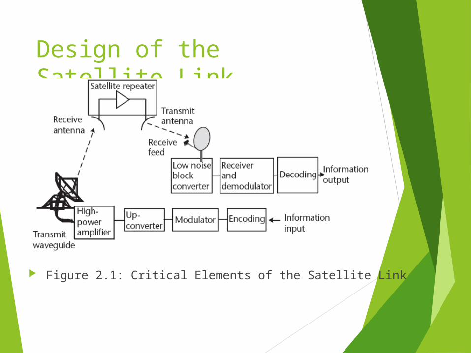
Figure 2.1: Critical Elements of the Satellite Link
Design of the Satellite Link The example shows a large hub type Earth
station in the uplink and a small VSAT in the downlink;
The satellite is represented by a simple frequency translating type repeater (e.g., a bent pipe).
Most geostationary satellites employ bent-pipe repeaters since these allow the widest range of services and communication techniques.
Design of the Satellite Link Bidirectional (duplex) communication
occurs with a separate transmission from each Earth station.
Due to the analog nature of the radio frequency link, each element contributes a gain or loss to the link and may add noise and interference as well.
Design of the Satellite Link The result in the overall performance is
presented in terms of the ratio of carrier power to noise (the carrier-to-noise ratio, C/N) and, ultimately, information quality (bit error rate, video impairment, or audio fidelity).
Done properly, this analysis can predict if the link will work with satisfactory quality based on the specifications of the ground and space components.
Any uncertainty can be covered by providing an appropriate amount of link margin, which is over and above the C/N needed to deal with propagation effects and nonlinearity in the Earth stations and satellite repeater.
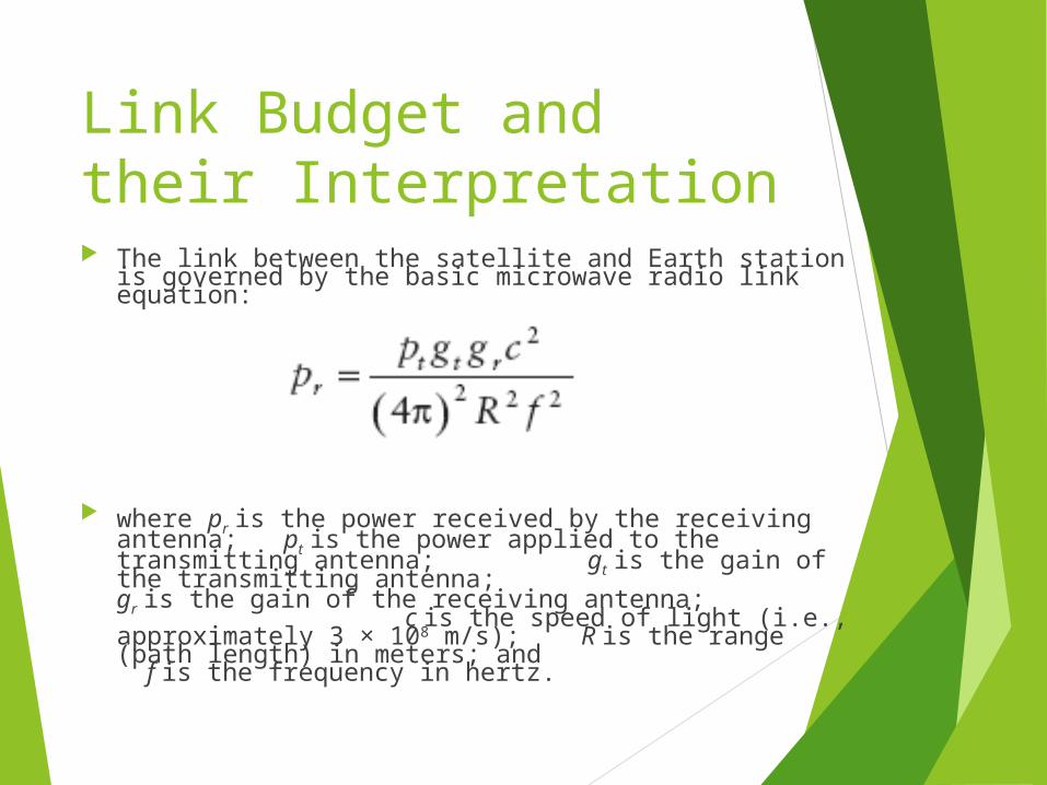
Link Budget and their Interpretation The link between the satellite and Earth station is governed by the basic microwave radio link equation:
where pr is the power received by the receiving antenna; pt is the power applied to the transmitting antenna; gt is the gain of the transmitting antenna; gr is the gain of the receiving antenna; c is the speed of light (i.e., approximately 3 × 10⁸ m/s); R is the range (path length) in meters; and f is the frequency in hertz.
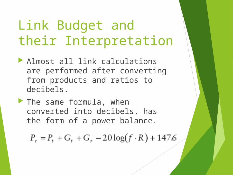
Link Budget and their Interpretation Almost all link calculations are
performed after converting from products and ratios to decibels.
The same formula, when converted into decibels, has the form of a power balance.
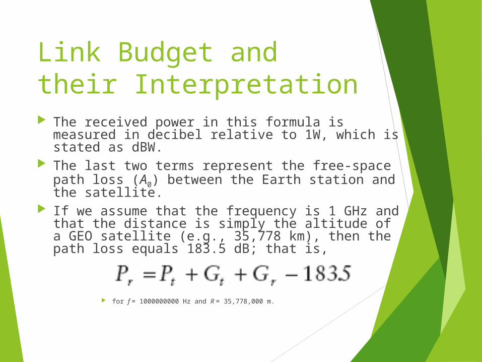
Link Budget and their Interpretation The received power in this formula is measured
in decibel relative to 1W, which is stated as dBW. The last two terms represent the free-space path
loss (A0) between the Earth station and the satellite.
If we assume that the frequency is 1 GHz and that the distance is simply the altitude of a GEO satellite (e.g., 35,778 km), then the path loss equals 183.5 dB; that is,
for f = 1000000000 Hz and R = 35,778,000 m.
Link Budget and their Interpretation
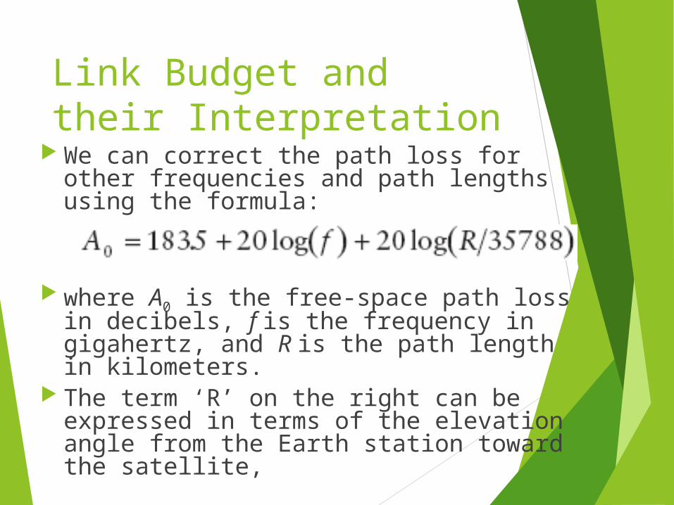
We can correct the path loss for other frequencies and path lengths using the formula:
where A0 is the free-space path loss in decibels, f is the frequency in gigahertz, and R is the path length in kilometers.
The term ‘R’ on the right can be expressed in terms of the elevation angle from the Earth station toward the satellite,
Link Budget and their Interpretation
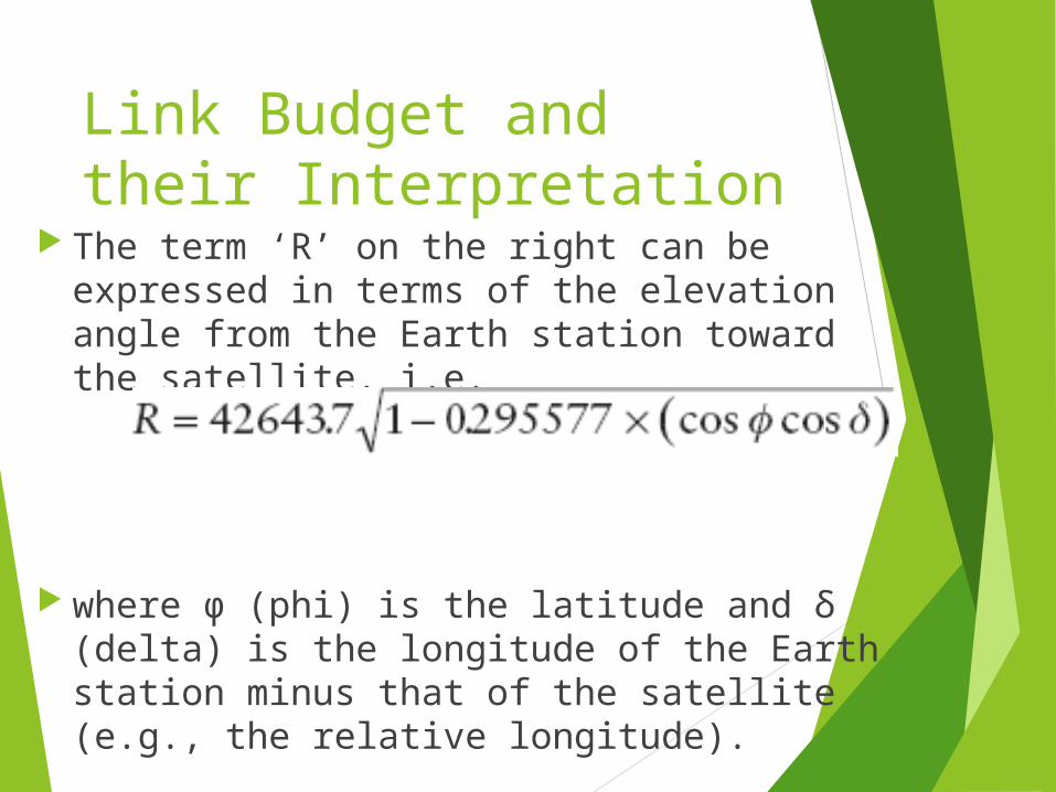
The term ‘R’ on the right can be expressed in terms of the elevation angle from the Earth station toward the satellite. i.e.
where φ (phi) is the latitude and δ (delta) is the longitude of the Earth station minus that of the satellite (e.g., the relative longitude).
Link Budget and their Interpretation
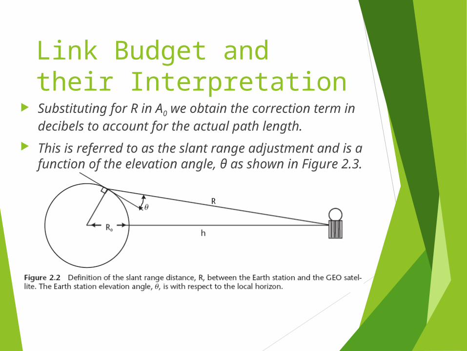
Substituting for R in A0 we obtain the correction term in decibels to account for the actual path length.
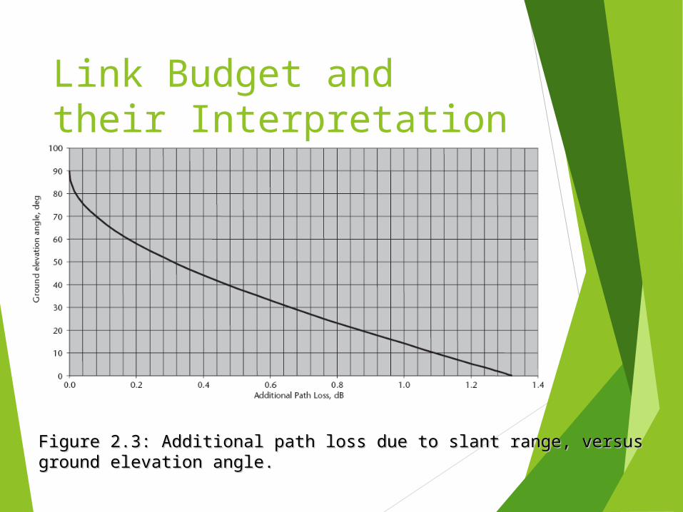
This is referred to as the slant range adjustment and is a function of the elevation angle, θ as shown in Figure 2.3.
Link Budget and their Interpretation
Figure 2.3: Additional path loss due to slant range, versus ground Figure 2.3: Additional path loss due to slant range, versus ground elevation angle.elevation angle.
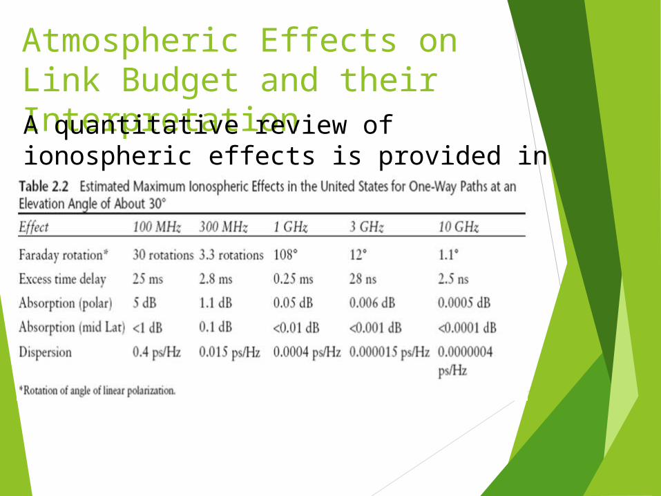
Atmospheric Effects on Link Budget and their InterpretationA quantitative review of ionospheric effects is provided in table below:
Atmospheric Effects on Link Budget and their Interpretation Ionospheric effects include effects of:
Faraday rotation, time delay, refraction, and dispersion.
It is clear from the data that Ionospheric effects are not significant at frequencies of 10 GHz and above,
but must be considered at L-, S-, and C-bands (L being the worst).
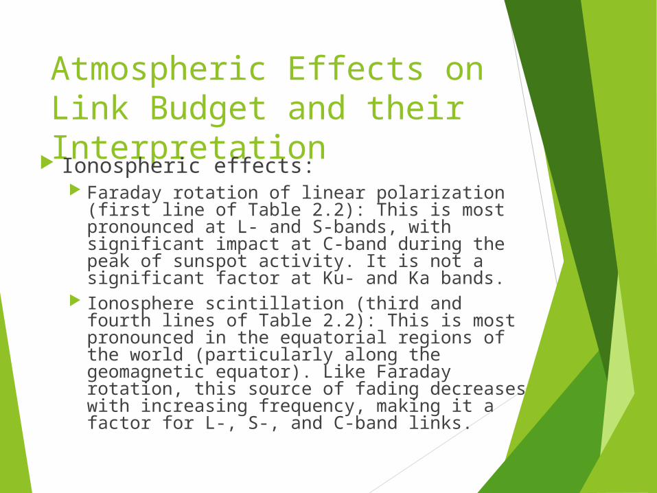
Atmospheric Effects on Link Budget and their Interpretation Ionospheric effects:
Faraday rotation of linear polarization (first line of Table 2.2): This is most pronounced at L- and S-bands, with significant impact at C-band during the peak of sunspot activity. It is not a significant factor at Ku- and Ka bands.
Ionosphere scintillation (third and fourth lines of Table 2.2): This is most pronounced in the equatorial regions of the world (particularly along the geomagnetic equator). Like Faraday rotation, this source of fading decreases with increasing frequency, making it a factor for L-, S-, and C-band links.
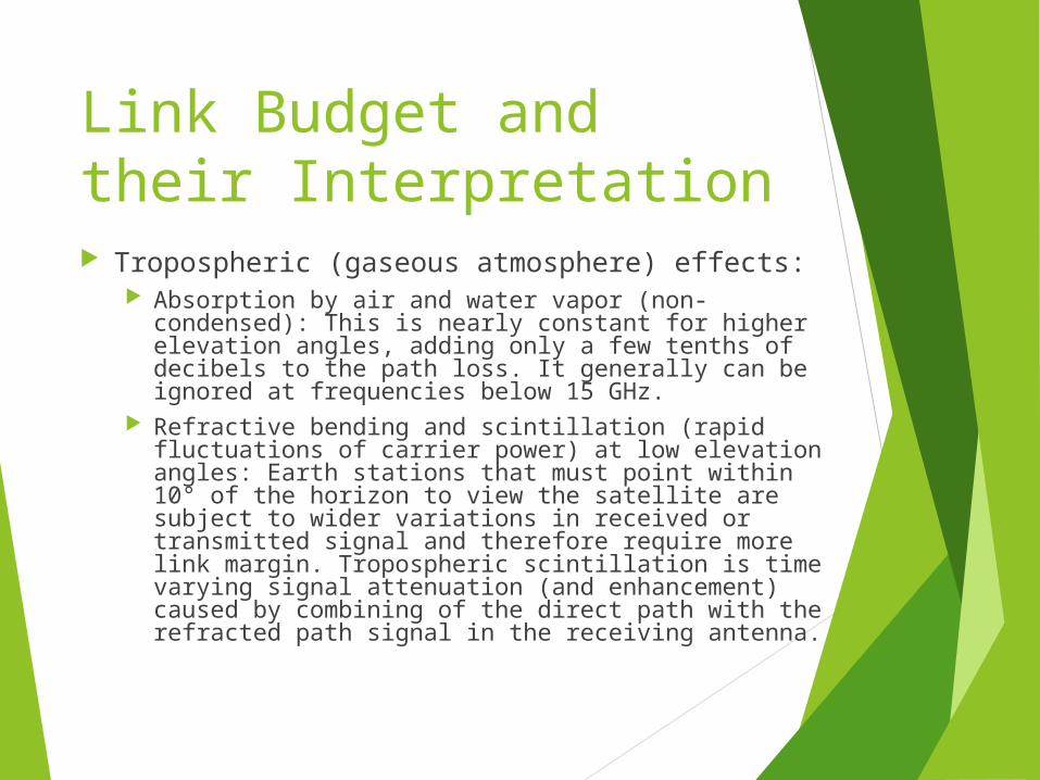
Link Budget and their Interpretation Tropospheric (gaseous atmosphere) effects:
Absorption by air and water vapor (non-condensed): This is nearly constant for higher elevation angles, adding only a few tenths of decibels to the path loss. It generally can be ignored at frequencies below 15 GHz.
Refractive bending and scintillation (rapid fluctuations of carrier power) at low elevation angles: Earth stations that must point within 10° of the horizon to view the satellite are subject to wider variations in received or transmitted signal and therefore require more link margin. Tropospheric scintillation is time varying signal attenuation (and enhancement) caused by combining of the direct path with the refracted path signal in the receiving antenna.
Link Budget and their Interpretation
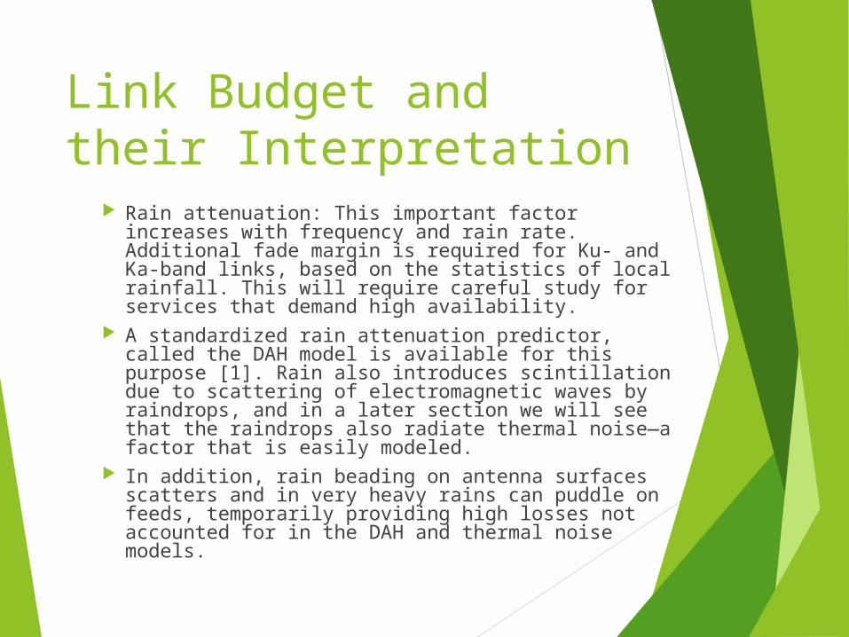
Rain attenuation: This important factor increases with frequency and rain rate. Additional fade margin is required for Ku- and Ka-band links, based on the statistics of local rainfall. This will require careful study for services that demand high availability.
A standardized rain attenuation predictor, called the DAH model is available for this purpose [1]. Rain also introduces scintillation due to scattering of electromagnetic waves by raindrops, and in a later section we will see that the raindrops also radiate thermal noise—a factor that is easily modeled.
In addition, rain beading on antenna surfaces scatters and in very heavy rains can puddle on feeds, temporarily providing high losses not accounted for in the DAH and thermal noise models.
Link Budget Example
Satellite application engineers need to assess and allocate performance for each source of gain and loss. The link budget is the most effective means since it can address and display all of the components of the power balance equation, expressed in decibels. In the past, each engineer was free to create a personalized methodology and format for their own link budgets. This worked adequately as long as the same person continued to do the work. Problems arose, however, when link budgets were exchanged between engineers, as formats and assumptions varied. A standardized link budget software tool should be used that performs all of the relevant calculations and presents the results in a clear and complete manner.
Link Budget Example We will now evaluate a specific example using a
simplified link budget containing the primary contributors. This will provide a typical format and some guidelines for
a practical approach. Separate uplink and downlink budgets are provided; our
evaluation of the total end-to-end link presumes the use of a bent-pipe repeater.
This is one that transfers both carrier and noise from the uplink to the downlink, with only a frequency translation and amplification.
The three constituents are often shown in a single table, but dividing them should make the development of the process clearer for readers.
The detailed engineering comes into play with the development of each entry of the table.
Several of the entries are calculated using straightforward mathematical equations; others must be obtained through actual measurements or at least estimates thereof.
Link Budget Example
This particular example is for a C-band digital video link at 40 Mbps, which is capable of transmitting 8 to 12 TV channels using the Motion Picture Experts Group 2 (MPEG 2) standard.
Link Budget Example:Downlink Budget
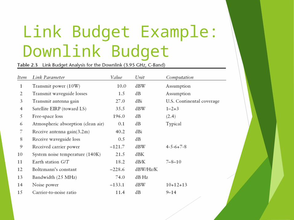
The following Table 2.3 presents the downlink budget in a manner that identifies the characteristics of the satellite transmitter and antenna, the path, the receiving antenna, and the expected performance of the Earth station receiver.
It contains the elements that select the desired radio signal (i.e., the carrier) and demodulates the useful information (i.e., the digital baseband containing the MPEG 2 “transport” bit stream).
Once converted back to baseband, the transmission can be applied to other processes, such as de-multiplexing, decryption, and digital-to-analog conversion (D/A conversion).
Link Budget Example:Downlink Budget
Link Budget Example:Downlink Budget
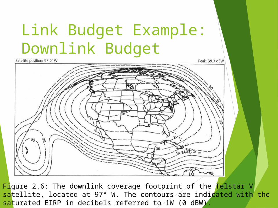
The following figure provides the horizontal downlink coverage of Telstar V, a typical C-band satellite that serves the United States.
Each contour shows a constant level of effective isotropic radiated power (EIRP) (the value at saturation of the transponder power amplifier).
Assuming the receiving Earth station is in Los Angeles, it is possible to interpolate between the contours and estimate a value of 38.5 dBW.
Link Budget Example:Downlink Budget
Figure 2.6: The downlink coverage footprint of the Telstar V satellite, located at 97° W. The contours are indicated with the saturated EIRP in decibels referred to 1W (0 dBW).
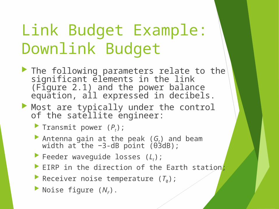
Link Budget Example:Downlink Budget The following parameters relate to the
significant elements in the link (Figure 2.1) and the power balance equation, all expressed in decibels.
Most are typically under the control of the satellite engineer: Transmit power (Pt); Antenna gain at the peak (Gt) and beam width at
the −3-dB point (θ3dB); Feeder waveguide losses (Lt); EIRP in the direction of the Earth station; Receiver noise temperature (T0); Noise figure (NF).
Link Budget Example:Downlink Budget
System noise temperature (Tsys) is the sum of T0 and the noise contribution of the receive antenna (Ta).
The overall Earth station figure of merit is defined as the ratio of receive gain to system noise temperature expressed in decibels per Kelvin—for example, G/T
The same can be said of EIRP for the transmit case. Reception is improved if either the gain is increased or the noise temperature is decreased; hence the use of a ratio.
Link Budget Example:Downlink Budget Each of the link parameters relates to a specific
piece of hardware or some property of the microwave path between space and ground.
A good way to develop the link budget is to prepare it with a spreadsheet program.
This permits the designer to include the various formulas directly in the budget, thus avoiding the problem of external calculation or the potential for arithmetic error (which still exists if the formulas are wrong or one adds losses instead of subtracting them).
Commercial link budget software, such as SatMaster Pro from Arrowe Technical Services, does the same job but in a standardized fashion.
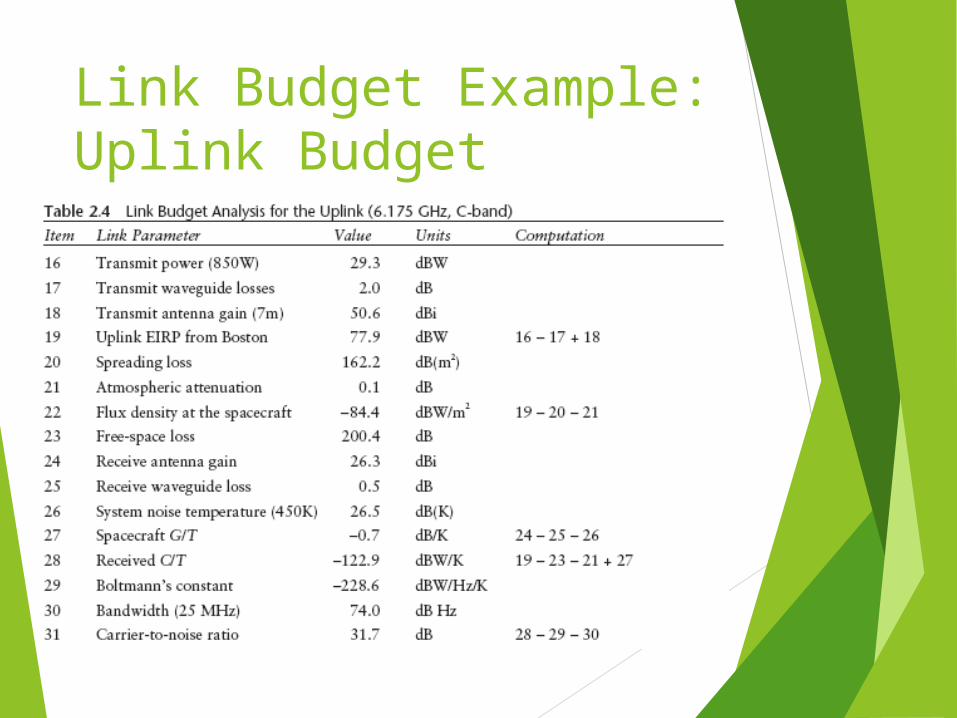
Link Budget Example:Uplink Budget
Link Budget Example:Uplink Budget
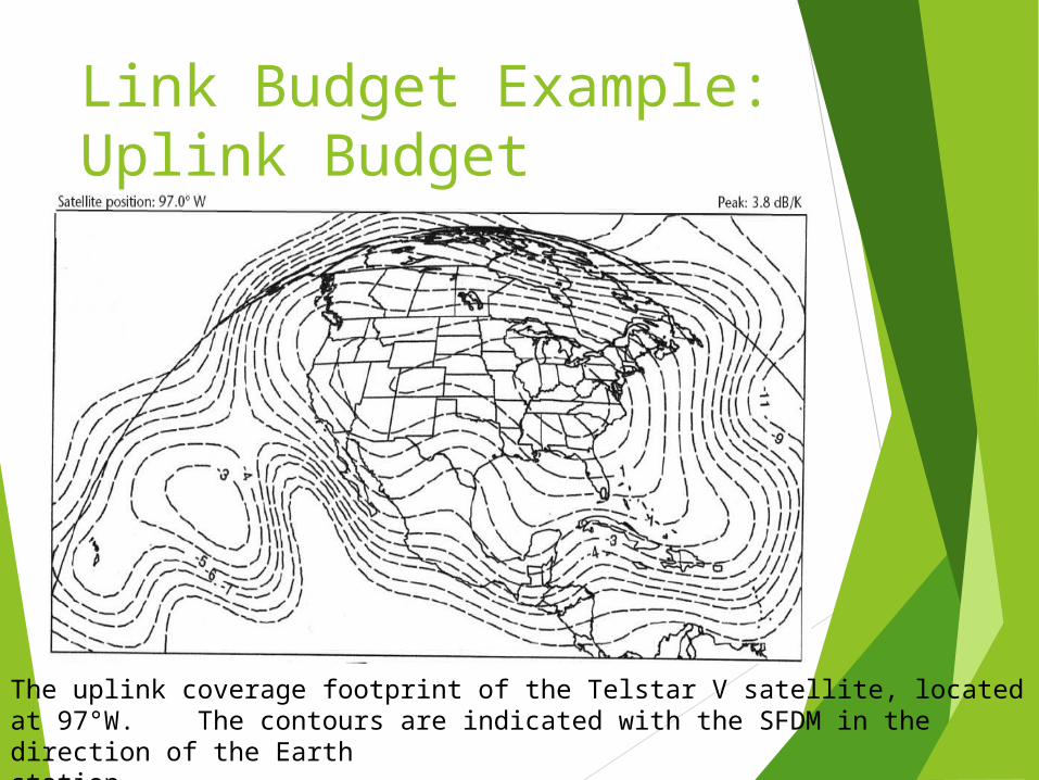
The uplink coverage footprint of the Telstar V satellite, located at 97°W. The contours are indicated with the SFDM in the direction of the Earthstation.
Link Budget Example:Uplink Budget The repeater in this design is a simple bent pipe
that does not alter or recover data from the transmission from the uplink. The noise on the uplink (e.g., N in the denominator of C/N) will be transferred directly to the downlink and added to the downlink noise.
In a baseband processing type of repeater, the uplink carrier is demodulated within the satellite and only the bits themselves are transferred to the downlink.
In such case, the uplink noise only produces bit errors (and possibly frame errors, depending on the modulation and multiple access scheme) that transfer over the re-modulated carrier.
This is a complex process and can only be assessed for the particular transmission system design in a digital processing satellite.
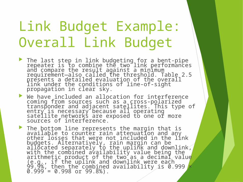
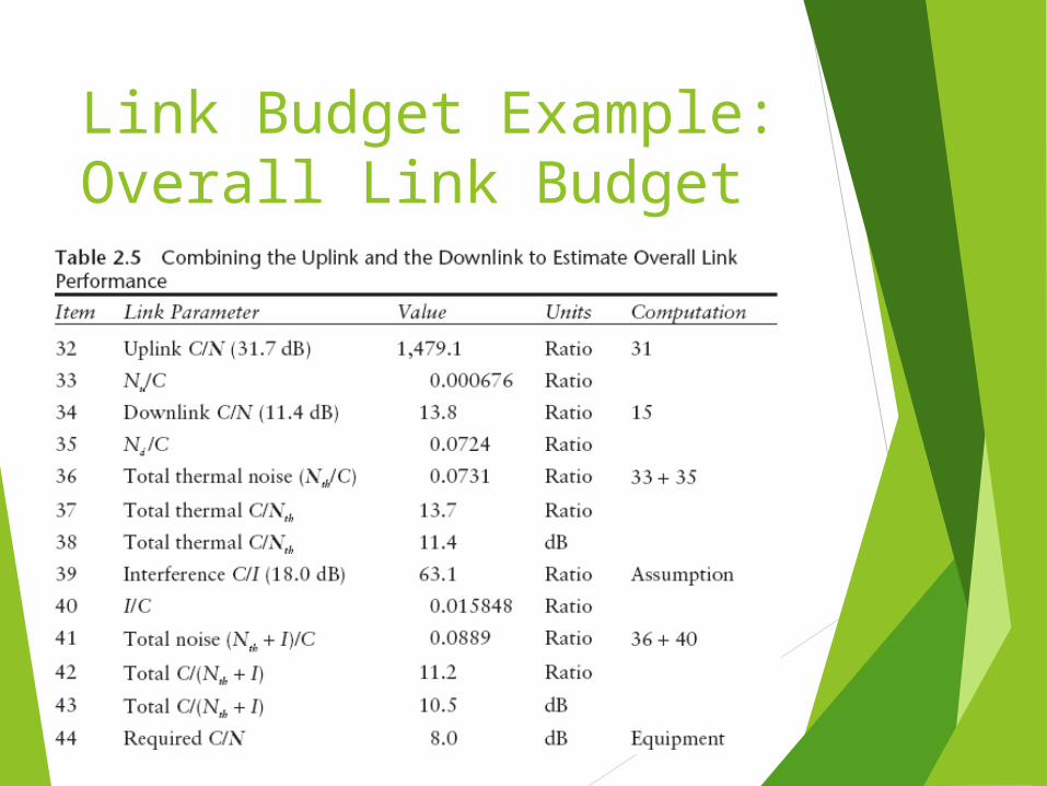
Link Budget Example:Overall Link Budget The last step in link budgeting for a bent-pipe repeater is to combine the two link performances and compare the result against a minimum requirement—also called the threshold. Table 2.5 presents a detailed evaluation of the overall link under the conditions of line-of-sight propagation in clear sky. We have included an allocation for interference coming from sources such as a cross-polarized transponder and adjacent satellites. This type of entry is necessary because all operating satellite networks are exposed to one or more sources of interference. The bottom line represents the margin that is available to counter rain attenuation and any other losses that were not included in the link budgets. Alternatively, rain margin can be allocated separately to the uplink and downlink, with the combined availability value being the arithmetic product of the two as a decimal value (e.g., if the uplink and downlink were each 99.9%, then the combined availability is 0.999 × 0.999 = 0.998 or 99.8%).
Link Budget Example:Overall Link Budget
Link Budget Summary
Over estimate link specification Downlink Budget Uplink Budget Overall Link Budget
Softwares for Satellite Calculations http://www.satellite-calculations.com http://science.nasa.gov/realtime/ http://www.qsl.net/kd2bd/predict.htm
l

Q&A
????
![[PPT]An Introduction to Software-Defined Networking … · Web viewSoftware 2016-02-21 Reviewing traditional networking Examples for motivating SDN Enabling networking as developing](https://static.fdocuments.net/doc/165x107/5b04ee627f8b9a3c378e5567/pptan-introduction-to-software-defined-networking-viewsoftware-2016-02-21.jpg)


![[PPT]Introduction to Networking & telecommunicationsa_illia/cis3200/Notes/MIS3200Class2.ppt · Web viewTitle Introduction to Networking & telecommunications Author x Last modified](https://static.fdocuments.net/doc/165x107/5b065ddc7f8b9a58148cbd1d/pptintroduction-to-networking-t-ailliacis3200notesmis3200class2pptweb-viewtitle.jpg)