Notes on Heavy Fuel Oilww2.eagle.org/content/dam/eagle/rules-and-guides/curre… · ·...
68
NOTES ON HEAVY FUEL OIL 1984 American Bureau of Shipping Incorporated by Act of Legislature of the State of New York 1862 Copyright 2001 American Bureau of Shipping ABS Plaza 16855 Northchase Drive Houston, TX 77060 USA
Transcript of Notes on Heavy Fuel Oilww2.eagle.org/content/dam/eagle/rules-and-guides/curre… · ·...
NOTES ON
HEAVY FUEL OIL
1984
American Bureau of ShippingIncorporated by Act of Legislature ofthe State of New York 1862
Copyright 2001American Bureau of ShippingABS Plaza16855 Northchase DriveHouston, TX 77060 USA

ABS NOTES ON HEAVY FUEL OIL 1984 1
NOTES ON
HEAVY FUEL OIL
CONTENTSSECTION 1 Introduction............................................................... 3
1 Diesel Power Plants and Fuels ................................ 3
SECTION 2 Marine Fuel Oil Origins and the Influence ofRefinery Processes................................................... 5
1 Crude Oil Sources.................................................... 7
3 Refinery Processes .................................................. 8
5 Market Influences on Marine Fuel Quality.............. 13
SECTION 3 Marine Fuel Oil Properties and Characteristicsand Their Impact on the Diesel Engine.................. 15
1 Marine Fuel Oil Characteristic Properties .............. 17
3 Marine Fuel Oil Contaminants................................ 28
SECTION 4 Fuel Sampling and Analysis................................... 33
1 Sampling Procedures............................................. 36
3 Shoreside Analysis................................................. 37
5 Shipboard Analyses ............................................... 37
7 Fuel Specifications and Standards......................... 38
SECTION 5 Shipboard Fuel Handling and Treatment forDiesel Engines ........................................................ 39
1 Marine Diesel Oil Systems..................................... 41
3 Heavy Fuel Oil Systems......................................... 43
5 Operating Guidelines and Recommendations ....... 49
7 Recommended Procedures for the OnboardTreatment of Problem Fuels: Very Poor Qualityor Highly Contaminated Fuel Oils .......................... 51
APPENDIX 1 Glossary and Abbreviations................................... 59
Glossary .............................................................................. 61
List of Abbreviations............................................................ 65

ABS NOTES ON HEAVY FUEL OIL 1984 3
S E C T I O N 1 Introduction
1 Diesel Power Plants and Fuels
Shipowners and operators, with increasing frequency, are seeing their vessels bunkered with fuelswhich, as a minimum, have significantly increased the crews’ fuel handling and treatment workload;and, in the extreme, have caused catastrophic diesel engine failures. These problems are not limited tospecific diesel engine types nor are they restricted to a narrow range of fuel grades. It is becomingapparent that no operator is immune. It also is evident that the future holds little prospect forimproved quality. The increasing use of some poorer grades of crude oil as feed stock and moreintensive refining practices have produced continued degradation in the quality of residual oils andblends, as well as some contamination of previously clean marine diesel oils (MDO).
Concurrent with continued fuel quality degradation, diesel engine designers have been increasing theMean Effective Pressures (M.E.P.) of engines in a never-ending search for higher power outputs (percylinder) and lower fuel consumption rates. The higher M.E.P.’s result in higher piston ring/linerloadings which can accelerate bore wear rates when poor quality heavy fuel oils are burned.
Because of its very small market share, the marine industry has little influence on world petroleumprices and refinery practices. Consequently, the ship operator must equip his ships with the necessarytools to cope with the escalating problem of degraded fuel quality.
The diesel’s capability to burn worldwide commercial grades of marine fuel oils is dependent uponthe range of significant fuel characteristics and the level of contaminants in the fuel oil. As fuel gradeand quality decrease, the impact on diesel engine operating reliability and economy will be stronglyinfluenced by the ability of shipboard fuel systems to provide properly treated fuel.
To adequately assess the influence of fuel quality on the operation of diesel engines and their supportsystems, such as the fuel storage, transfer, and service systems, a basic working knowledge of fuelcharacteristics and their impact on the performance of diesel engines and shipboard fuel handling andtreatment systems is required. It is the intent of this document to provide the reader with thisnecessary overview including:
i) The influence of crude oil sources and various refining procedures on the ultimate quality ofmarine fuels as bunkered
ii) The impact of marine fuel characteristic properties and contaminants on diesel engine andsupport system operation
iii) Fuel sampling and analysis techniques and laboratory and onboard test procedures for variousmarine fuel properties
iv) A review and functional description of storage, treatment, transfer and service systems fordiesel engines operated on marine diesel, and heavy marine fuels
v) Typical components and/or subsystems available for the onboard treatment of various fuelproperties which exceed specified levels


ABS NOTES ON HEAVY FUEL OIL 1984 5
S E C T I O N 2 Marine Fuel Oil Origins and theInfluence of Refinery Processes
CONTENTS1 Crude Oil Sources ................................................................... 7
3 Refinery Processes ................................................................. 8
3.1 Atmospheric Distillation ............................................................ 8
3.3 Vacuum Distillation................................................................. 10
3.5 Thermal Cracking ................................................................... 10
3.7 Catalytic Cracking .................................................................. 13
3.9 Refinery Blending and Storage .............................................. 13
5 Market Influences on Marine Fuel Quality ........................... 13
TABLE 1 Crude Source Related Properties andCharacteristics............................................................. 8
TABLE 2 Effect of Crude Source on Various Product Yieldsand Characteristics...................................................... 9
TABLE 3 Refining Process Related Characteristics andProperties................................................................... 10
FIGURE 1 Atmospheric or Straight-Run Method of Crude OilDistillation .................................................................. 11
FIGURE 2 Vacuum Distillation and Vis-breaking Processes.... 11
FIGURE 3 Thermal Cracking Process........................................ 12
FIGURE 4 Catalytic Cracking Process....................................... 12

ABS NOTES ON HEAVY FUEL OIL 1984 7
S E C T I O N 2 Marine Fuel Oil Origins and theInfluence of Refinery Processes
1 Crude Oil SourcesPetroleum products, in general, whether diesel oil, lubricating oil, light fuel oil or heavy fuel oil, areessentially composed of two major elements, carbon and hydrogen. The combination of these twoelements is called a hydrocarbon. Its ultimate source is crude oil as found in its natural states invarious geological formations throughout the world.
Crude oil consists of a very broad spectrum of hydrocarbons ranging from very light, volatile gases toheavy residues. Residual fuels are, in effect, the heavy residues resulting from the refining process.The more desired hydrocarbons and some less desirable ones are extracted from crude oil by therefining process. Similar processes are also used to reconstruct the less desirable hydrocarbon residuesinto forms that can meet current market demand. The hydrocarbons mostly found in marine fuel oilsfall into four (4) main classes − paraffinic, aromatic, naphthenic and olefinic. These basic compoundtypes are further categorized below.
Paraffinic hydrocarbons (CNH(2N+2)) are lower in specific gravity than aromatic hydrocarbons of thesame boiling point, while naphthenic and olefinic compounds are intermediate in density. Theirresistance to chemical change or oxidation is very good. These hydrocarbons are clean burning, andthus are desirable in distillates such as gas oil or diesel oil.
Aromatic hydrocarbons (CNH(2N-6)) possess a much higher specific gravity than the other threeclasses. Aromatics are very stable under heat and are chemically active to a moderate degree. Thearomatic compounds contain a higher proportion of carbon than the other hydrocarbon types. Due tothis characteristic, they have a tendency to smoke, which somewhat limits their use in diesel engines.
Naphthenic hydrocarbons (CNH2N-ring type) are extremely stable, cyclo-ring compounds and in manycases have more stability than the paraffins. These hydrocarbons are more commonly found in heavymarine fuel oils rather than distillate oils.
Olefinic hydrocarbons (CNH2-straight chain) are more chemically active than the other three classesof hydrocarbons. Olefins are subject to oxidation or polymerization, forming gums. Olefins are notpresent in large amounts in straight-run distillates, but are found in large quantities in cracked marinefuel oils.
While crude oil is the source of the various hydrocarbon compounds in marine fuels from whichthermal energy is produced during combustion in a diesel engine, it also is the source of manyundesirable properties and characteristics which are carried over in the refining process to theresultant petroleum product. Section 2, Table 1 lists the principal contaminants which are related tothe source of the crude oil. These contaminants will be concentrated in heavy fuel oils which havebeen subjected to intensive refining.
Section 2 Marine Fuel Oil Origins and the Influence of refinery Processes 2
8 ABS NOTES ON HEAVY FUEL OIL 1984
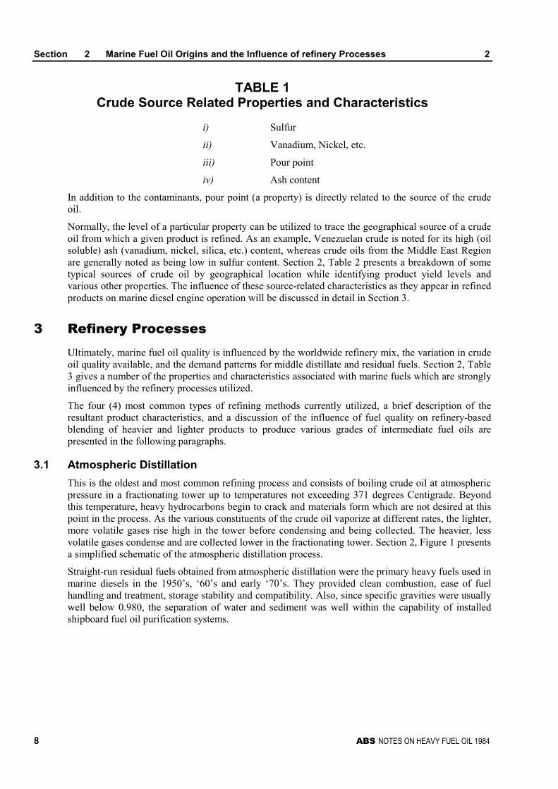
TABLE 1Crude Source Related Properties and Characteristics
i) Sulfur
ii) Vanadium, Nickel, etc.
iii) Pour point
iv) Ash content
In addition to the contaminants, pour point (a property) is directly related to the source of the crudeoil.
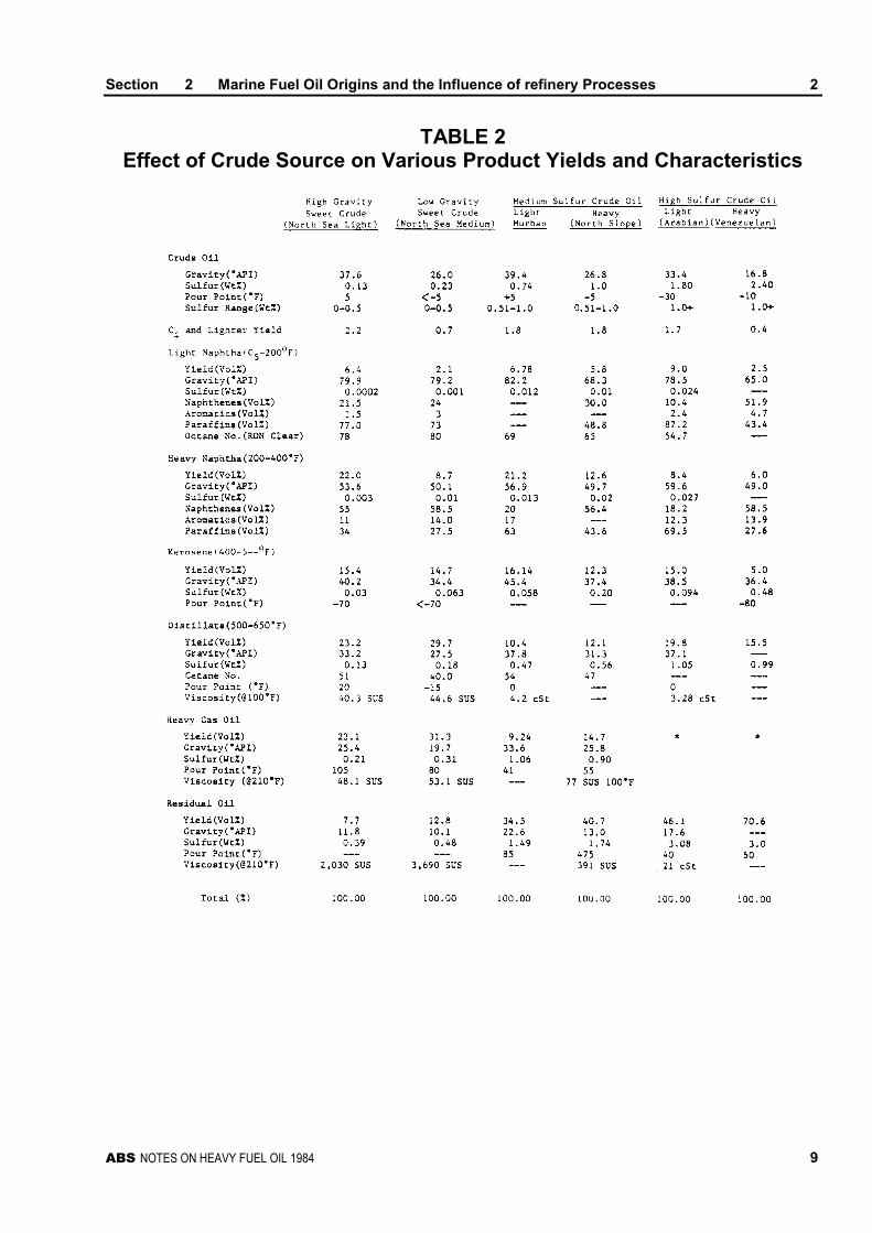
Normally, the level of a particular property can be utilized to trace the geographical source of a crudeoil from which a given product is refined. As an example, Venezuelan crude is noted for its high (oilsoluble) ash (vanadium, nickel, silica, etc.) content, whereas crude oils from the Middle East Regionare generally noted as being low in sulfur content. Section 2, Table 2 presents a breakdown of sometypical sources of crude oil by geographical location while identifying product yield levels andvarious other properties. The influence of these source-related characteristics as they appear in refinedproducts on marine diesel engine operation will be discussed in detail in Section 3.
3 Refinery ProcessesUltimately, marine fuel oil quality is influenced by the worldwide refinery mix, the variation in crudeoil quality available, and the demand patterns for middle distillate and residual fuels. Section 2, Table3 gives a number of the properties and characteristics associated with marine fuels which are stronglyinfluenced by the refinery processes utilized.
The four (4) most common types of refining methods currently utilized, a brief description of theresultant product characteristics, and a discussion of the influence of fuel quality on refinery-basedblending of heavier and lighter products to produce various grades of intermediate fuel oils arepresented in the following paragraphs.
3.1 Atmospheric Distillation
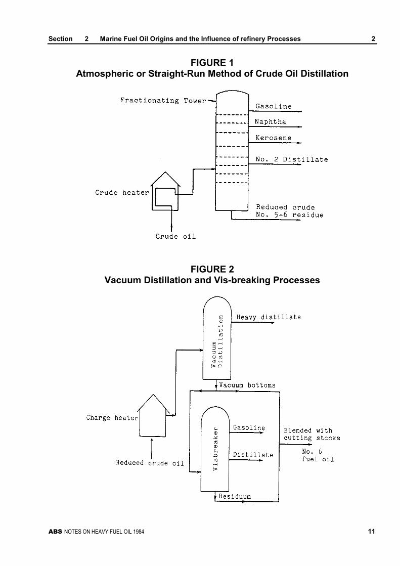
This is the oldest and most common refining process and consists of boiling crude oil at atmosphericpressure in a fractionating tower up to temperatures not exceeding 371 degrees Centigrade. Beyondthis temperature, heavy hydrocarbons begin to crack and materials form which are not desired at thispoint in the process. As the various constituents of the crude oil vaporize at different rates, the lighter,more volatile gases rise high in the tower before condensing and being collected. The heavier, lessvolatile gases condense and are collected lower in the fractionating tower. Section 2, Figure 1 presentsa simplified schematic of the atmospheric distillation process.
Straight-run residual fuels obtained from atmospheric distillation were the primary heavy fuels used inmarine diesels in the 1950’s, ‘60’s and early ‘70’s. They provided clean combustion, ease of fuelhandling and treatment, storage stability and compatibility. Also, since specific gravities were usuallywell below 0.980, the separation of water and sediment was well within the capability of installedshipboard fuel oil purification systems.
Section 2 Marine Fuel Oil Origins and the Influence of refinery Processes 2
ABS NOTES ON HEAVY FUEL OIL 1984 9
TABLE 2Effect of Crude Source on Various Product Yields and Characteristics
Section 2 Marine Fuel Oil Origins and the Influence of refinery Processes 2
10 ABS NOTES ON HEAVY FUEL OIL 1984
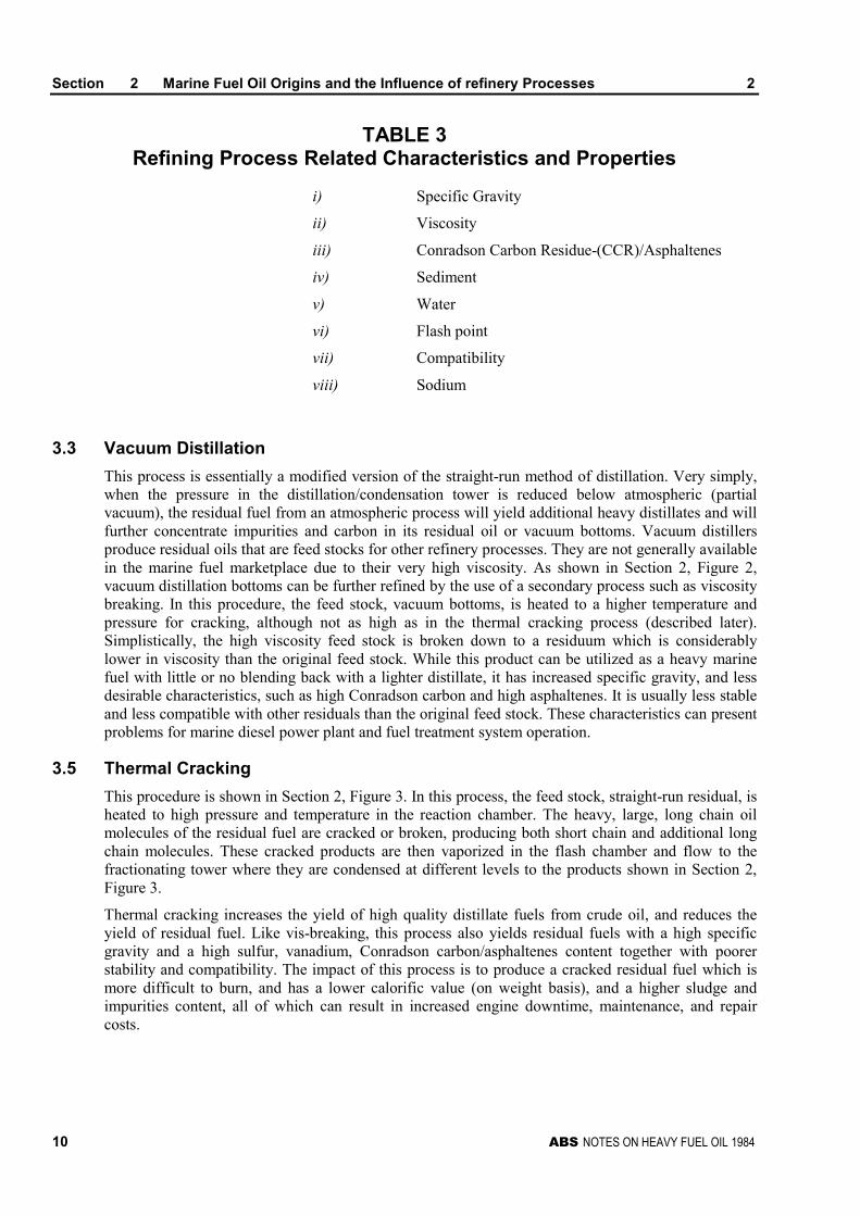
TABLE 3Refining Process Related Characteristics and Properties
i) Specific Gravity
ii) Viscosity
iii) Conradson Carbon Residue-(CCR)/Asphaltenes
iv) Sediment
v) Water
vi) Flash point
vii) Compatibility
viii) Sodium
3.3 Vacuum Distillation
This process is essentially a modified version of the straight-run method of distillation. Very simply,when the pressure in the distillation/condensation tower is reduced below atmospheric (partialvacuum), the residual fuel from an atmospheric process will yield additional heavy distillates and willfurther concentrate impurities and carbon in its residual oil or vacuum bottoms. Vacuum distillersproduce residual oils that are feed stocks for other refinery processes. They are not generally availablein the marine fuel marketplace due to their very high viscosity. As shown in Section 2, Figure 2,vacuum distillation bottoms can be further refined by the use of a secondary process such as viscositybreaking. In this procedure, the feed stock, vacuum bottoms, is heated to a higher temperature andpressure for cracking, although not as high as in the thermal cracking process (described later).Simplistically, the high viscosity feed stock is broken down to a residuum which is considerablylower in viscosity than the original feed stock. While this product can be utilized as a heavy marinefuel with little or no blending back with a lighter distillate, it has increased specific gravity, and lessdesirable characteristics, such as high Conradson carbon and high asphaltenes. It is usually less stableand less compatible with other residuals than the original feed stock. These characteristics can presentproblems for marine diesel power plant and fuel treatment system operation.
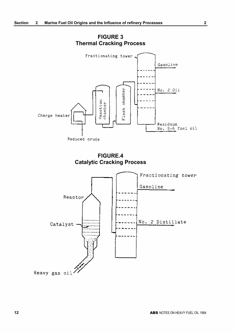
3.5 Thermal Cracking
This procedure is shown in Section 2, Figure 3. In this process, the feed stock, straight-run residual, isheated to high pressure and temperature in the reaction chamber. The heavy, large, long chain oilmolecules of the residual fuel are cracked or broken, producing both short chain and additional longchain molecules. These cracked products are then vaporized in the flash chamber and flow to thefractionating tower where they are condensed at different levels to the products shown in Section 2,Figure 3.
Thermal cracking increases the yield of high quality distillate fuels from crude oil, and reduces theyield of residual fuel. Like vis-breaking, this process also yields residual fuels with a high specificgravity and a high sulfur, vanadium, Conradson carbon/asphaltenes content together with poorerstability and compatibility. The impact of this process is to produce a cracked residual fuel which ismore difficult to burn, and has a lower calorific value (on weight basis), and a higher sludge andimpurities content, all of which can result in increased engine downtime, maintenance, and repaircosts.
Section 2 Marine Fuel Oil Origins and the Influence of refinery Processes 2
ABS NOTES ON HEAVY FUEL OIL 1984 11
FIGURE 1Atmospheric or Straight-Run Method of Crude Oil Distillation
FIGURE 2Vacuum Distillation and Vis-breaking Processes
Section 2 Marine Fuel Oil Origins and the Influence of refinery Processes 2
12 ABS NOTES ON HEAVY FUEL OIL 1984
FIGURE 3Thermal Cracking Process
FIGURE.4Catalytic Cracking Process
Section 2 Marine Fuel Oil Origins and the Influence of refinery Processes 2
ABS NOTES ON HEAVY FUEL OIL 1984 13
3.7 Catalytic Cracking
This process is a variation of thermal cracking. It is shown diagrammatically in Section 2, Figure 4.Catalytic cracking, including fluidic catalytic cracking, (F.C.C.), are processes in which a chemicalcatalyst is used to increase the yield of the thermal cracking process. The presence of a powderedcatalyst added to the feed stock stream allows the breakdown of long chain molecules into lighter,short chain hydrocarbon molecules at lower pressures and temperatures. In addition, the fine,powdered catalyst used with the charge stock can carry over into the resultant cracked residuum. Thispowdered catalyst, sometimes referred to as “catalyst fines” or “cat cracker catalyst”, is very hard andextremely abrasive. It is not unlike fine sand, and can rapidly increase the wear of injection pumps,fuel valves, injectors, piston rings, piston ring grooves, liners, stuffing box seals, and turbochargerblading. Whenever a straight-run residual oil has been processed through an F.C.C. unit to produce acracked residuum, there is a very high probability that some of these abrasive catalyst particles,comprised of aluminum oxide and/or silicon dioxide, will be carried over and find their way into eventhe lightest blends of intermediate marine fuels derived from the contaminated cracked residuum.
3.9 Refinery Blending and Storage
While not part of the actual refining process, on-site refinery fuel blending, handling and storage canhave a significant impact on fuel quality as bunkered. By blending, less desirable cracked residual oilcan be made more attractive as fuel oil. This is accomplished by adding to a given quantity of residualoil a small amount of lighter distillate or cutter stock. It is not uncommon for these fuels to have beenproduced in different refinery units and even from different crude stocks. Thus, the potential forincompatibility problems to occur, such as sludge formation or stratification, exists.
Currently marine fuels bunkered as residual oils are in fact blends of deep cracked residuum andlighter distillate cutter stock. These have, as a result of increasing refinery yield demands on crudesupplies, all but replaced the straight-run residual fuels obtained from atmospheric distillation, whichcharacterized marine residual fuels of the past.
While the most significant portion of fuel contamination by water and debris normally occurs duringbarge transport, pipeline transport and tank farm storage at the refinery also can increase contaminantlevels prior to transport for shipboard use.
5 Market Influences on Marine Fuel QualityCurrent trends translate into heavier, higher sulfur crudes for worldwide refiners. This fact, combinedwith refinery upgradings to the more complex cracking process to produce higher per unit crudedistillate yields, will have a significant impact on the quality of cracked residuals and blended fuelsavailable to the marine industry.

ABS NOTES ON HEAVY FUEL OIL 1984 15
S E C T I O N 3 Marine Fuel Oil Properties andCharacteristics and Their Impacton the Diesel Engine
CONTENTS1 Marine Fuel Oil Characteristic Properties............................ 17
1.1 Viscosity ................................................................................. 17
1.3 Specific Gravity....................................................................... 20
1.5 Carbon Residue/Asphaltenes................................................. 21
1.7 Sulfur ...................................................................................... 22
1.9 Ash/Sediment ......................................................................... 23
1.11 Vanadium ............................................................................... 23
1.13 Compatibility ........................................................................... 24
1.15 Cetane .................................................................................... 24
1.17 Flash Point.............................................................................. 25
1.19 Pour Point............................................................................... 25
1.21 Heating Value......................................................................... 26
3 Marine Fuel Oil Contaminants .............................................. 28
3.1 Water ...................................................................................... 28
3.3 Sodium (Na) ........................................................................... 29
3.5 Sediment ................................................................................ 29
3.7 Alumina/Silica ......................................................................... 30
3.9 Sludge .................................................................................... 31
3.11 Fibers...................................................................................... 31
3.13 Oxidation Products ................................................................. 31
TABLE 1 Kinematic/Redwood Viscosity Equivalents ofTypical Marine Fuels.................................................. 19
FIGURE 1 Relationship between Redwood and SI ViscositySystems...................................................................... 19
FIGURE 2 Relationship between Temperature and Viscosityfor Marine Fuels ......................................................... 20
FIGURE 3 Relationship between Carbon/Hydrogen Ratioand Gross Heating Value and Carbon Atoms .......... 27
FIGURE 4 Heating Values Relative to Gravity and SulfurContent ....................................................................... 28
FIGURE 5 Sodium-Vanadium Phase Diagram........................... 30

ABS NOTES ON HEAVY FUEL OIL 1984 17
S E C T I O N 3 Marine Fuel Oil Properties andCharacteristics and Their Impacton the Diesel Engine
Marine fuel quality can significantly affect the performance, operation and maintenance of the dieselengine. To better understand the important effect of diesel fuels on the engine itself, it is important tohave a basic understanding of fuel characteristics, properties and contaminants which impact theoperation of a diesel engine and its fuel handling and fuel treatment systems.
Whereas the marine diesel engine is a very efficient power plant, it does have a higher degree ofsensitivity to specific fuel properties and contaminants than does the steam boiler. For the purposes ofthis document, a fuel property is considered to be a characteristic occurring in the fuel carried overfrom its crude source or which is the result of the refining processes by which it was produced. Acontaminant is considered as foreign matter introduced into a fuel as a result of refining, transport orstorage. This section will address the following properties and contaminants and their influence ondiesel engine operation.
Characteristic Properties
ViscositySpecific GravityCarbonResidue/Asphaltenes
AshVanadiumCompatibilityCetane
Flash PointPour PointHeating Value
Contaminants
WaterSodiumSedimentAlumina/Silica (CatalyticFines)
SludgeFibersOxidation Products (Gums,Varnish)
1 Marine Fuel Oil Characteristic Properties
1.1 Viscosity
Heavy fuel oils are normally purchased on the basis of a limiting viscosity due to storage, handling, orengine-related restrictions. Viscosity does not, however, carry a quality implication, regardless of thefact that many purchasers of marine fuel oils believe this to be the case. A false sense of qualityassurance has developed through the procurement, on the basis of viscosity only, of straight-run fueloils. As heavy fuel oils are produced in the future by more and more intensive secondary processing,the relationship between fuel oil viscosity and fuel oil quality becomes less and less meaningful.Today, as well as in the future, viscosity is an inadequate yardstick by which to judge heavy fuel oilquality.
Section 3 Marine Fuel Oil Properties and Characteristics and Their Impacton the Diesel Engine 3
18 ABS NOTES ON HEAVY FUEL OIL 1984
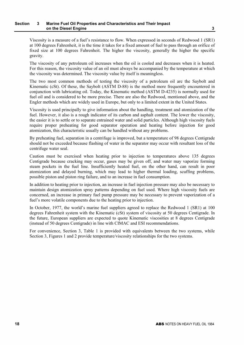
Viscosity is a measure of a fuel’s resistance to flow. When expressed in seconds of Redwood 1 (SR1)at 100 degrees Fahrenheit, it is the time it takes for a fixed amount of fuel to pass through an orifice offixed size at 100 degrees Fahrenheit. The higher the viscosity, generally the higher the specificgravity.
The viscosity of any petroleum oil increases when the oil is cooled and decreases when it is heated.For this reason, the viscosity value of an oil must always be accompanied by the temperature at whichthe viscosity was determined. The viscosity value by itself is meaningless.
The two most common methods of testing the viscosity of a petroleum oil are the Saybolt andKinematic (cSt). Of these, the Saybolt (ASTM D-88) is the method more frequently encountered inconjunction with lubricating oil. Today, the Kinematic method (ASTM D-4235) is normally used forfuel oil and is considered to be more precise. There are also the Redwood, mentioned above, and theEngler methods which are widely used in Europe, but only to a limited extent in the United States.
Viscosity is used principally to give information about the handling, treatment and atomization of thefuel. However, it also is a rough indicator of its carbon and asphalt content. The lower the viscosity,the easier it is to settle or to separate entrained water and solid particles. Although high viscosity fuelsrequire proper preheating for good separator operation and heating before injection for goodatomization, this characteristic usually can be handled without any problems.
By preheating fuel, separation in a centrifuge is improved, but a temperature of 98 degrees Centigradeshould not be exceeded because flashing of water in the separator may occur with resultant loss of thecentrifuge water seal.
Caution must be exercised when heating prior to injection to temperatures above 135 degreesCentigrade because cracking may occur, gases may be given off, and water may vaporize formingsteam pockets in the fuel line. Insufficiently heated fuel, on the other hand, can result in pooratomization and delayed burning, which may lead to higher thermal loading, scuffing problems,possible piston and piston ring failure, and to an increase in fuel consumption.
In addition to heating prior to injection, an increase in fuel injection pressure may also be necessary tomaintain design atomization spray patterns depending on fuel used. Where high viscosity fuels areconcerned, an increase in primary fuel pump pressure may be necessary to prevent vaporization of afuel’s more volatile components due to the heating prior to injection.
In October, 1977, the world’s marine fuel suppliers agreed to replace the Redwood 1 (SR1) at 100degrees Fahrenheit system with the Kinematic (cSt) system of viscosity at 50 degrees Centigrade. Inthe future, European suppliers are expected to quote Kinematic viscosities at 8 degrees Centigrade(instead of 50 degrees Centigrade) in line with CIMAC and ESI recommendations.
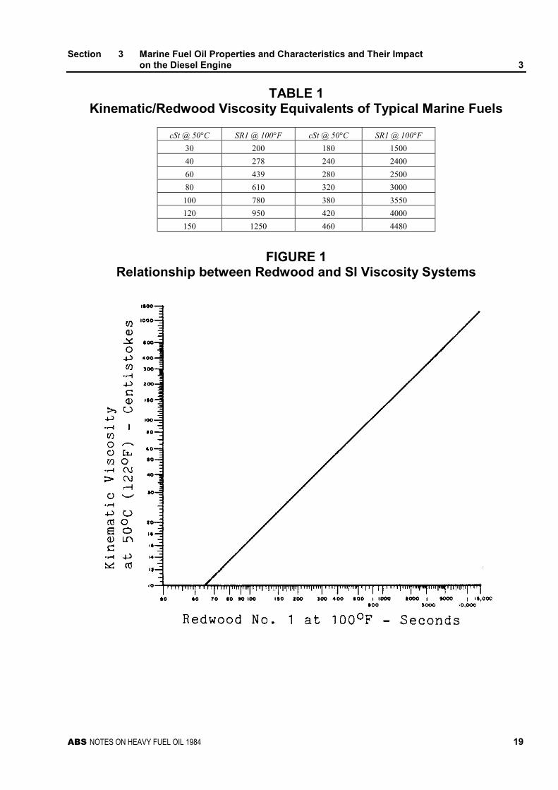
For convenience, Section 3, Table 1 is provided with equivalents between the two systems, whileSection 3, Figures 1 and 2 provide temperature/viscosity relationships for the two systems.
Section 3 Marine Fuel Oil Properties and Characteristics and Their Impacton the Diesel Engine 3
ABS NOTES ON HEAVY FUEL OIL 1984 19
TABLE 1Kinematic/Redwood Viscosity Equivalents of Typical Marine Fuels
cSt @ 50°C SR1 @ 100°F cSt @ 50°C SR1 @ 100°F
30 200 180 1500
40 278 240 2400
60 439 280 2500
80 610 320 3000
100 780 380 3550
120 950 420 4000
150 1250 460 4480
FIGURE 1Relationship between Redwood and SI Viscosity Systems
Section 3 Marine Fuel Oil Properties and Characteristics and Their Impacton the Diesel Engine 3
20 ABS NOTES ON HEAVY FUEL OIL 1984
FIGURE 2Relationship between Temperature and Viscosity for Marine Fuels
1.3 Specific Gravity
Specific gravity is defined as the ratio of the weight of a given volume of the product at 15 degreesCentigrade to the weight of an equal volume of water at the same temperature.
Specific gravity is determined by floating a hydrometer in the liquid and noting the point at which theliquid level intersects the hydrometer scale. Corrections must then be made in accordance with thetemperature of the sample at the time of test. The ASTM D-287 standard provides details on themethod.
The importance of specific gravity relative to diesel engine operation lies in the fact that today’sstandard fuel/water separating techniques are based upon the difference in density between the twosubstances. Therefore, as the specific gravity of fuel approaches 1.0, centrifuging becomes lesseffective. Since diesel engine fuels should be free of water and the salts normally dissolved therein,extra centrifuging capacity will be required for high gravity fuel. High specific gravity indicates aheavily cracked, aromatic fuel oil with poor combustion qualities, which can cause abnormal linerwear. This effect is most pronounced in smaller, higher speed diesels.
Heating the fuel prior to centrifuging assists in the separation process because the density of fuel oilchanges more rapidly with temperature than does the density of water. A viscosity decrease also helpscentrifuging. A maximum specific gravity of 0.991 (at 15 degrees Centigrade) can be handledsatisfactorily. Above this value the centrifugal purifier cannot repeatedly and successfully operate, dueto loss of its water seal. This 0.991 limit can vary under special circumstances. (See 5/7.7 “HighSpecific Gravity”).
Section 3 Marine Fuel Oil Properties and Characteristics and Their Impacton the Diesel Engine 3
ABS NOTES ON HEAVY FUEL OIL 1984 21
Specific gravity for future fuels is expected to rise to about 0.995. The major significance of thisincrease in specific gravity will be greater difficulty relative to water removal in settling tanks andcentrifuges. This trend toward higher specific gravity will mean also lower hydrogen-carbon ratios,which will increase the difficulty of achieving clean combustion or, conversely, will foster increasesin carbonaceous deposits and debris. This trend toward higher specific gravities has been dueprimarily to the more extensive use of secondary processing (vis-breaking and thermal or catalyticcracking) of heavier crude oils.
1.5 Carbon Residue/Asphaltenes
Conradson Carbon Residue (CCR) is a measure of the tendency of a fuel to form carbon depositsduring combustion and indicates the relative coke forming tendencies of a heavy oil. Carbon-richfuels are more difficult to burn and have combustion characteristics which lead to the formation ofsoot and carbon deposits. Since carbon deposits are a major source of abrasive wear, the CCR value isan important parameter for a diesel engine. The type of carbon also can affect abrasive wear.
Carbon residue is the percent of coked material remaining after a sample of fuel oil has been exposedto high temperatures under ASTM Method D-189 (Conradson) or D-524 (Ramsbottom).
Asphaltenes are those components of asphalt that are insoluble in petroleum naphtha and hot heptanebut are soluble in carbon disulfide and hot benzene. They can be hard and brittle and made up of largemacromolecules of high molecular weight, consisting of polynuclear hydrocarbon derivativescontaining carbon, hydrogen, sulfur, nitrogen, oxygen and, usually, the three heavy metals − nickel,iron and vanadium.
A high CCR/asphaltene level denotes a high residue level after combustion and may lead to ignitiondelay as well as after-burning of carbon deposits leading to engine fouling and abrasive wear. Poorengine performance caused by slow burning, high boiling point constituents results in higher thermalloading and changes in the rate of heat release in the cylinder.
Normally, most if not all of a heavy fuel oil injection should burn between top dead center (TDC) and90 degrees after TDC, with the expansion of generated gases acting on the piston to complete thepower stroke. After-burning is of particular concern because the increased time needed forcombustion exposes a greater area of cylinder liner to flame than would normally occur and subjectsthe cylinder lubricant to higher pressure and temperature stresses resulting in hot spots, severeradiation, and burning of the lube oil film. The latter leads to scuffing, cylinder wear and enginedeposits.
CCR is expressed as a percent of the whole fuel. Fuels with high CCR values have an increasingtendency to form carbon deposits on injection nozzles, pistons, and in the ports of two-stroke engines.This causes reduction in the efficiency and performance of those components and increased wear. Themaximum permissible CCR value depends on engine speed. The higher the speed, the shorter the timefor combustion and the more residue deposited; hence, acceptable CCR values should decrease asengine speed increases.
While two-cycle, slow speed engines are less affected by a high CCR than four-cycle engines, it doescontribute to increased fouling of gas ways and turbochargers, especially during low power operationor at idle. Idling should be limited to five to ten hours and be followed by running at full load to cleargas ways whenever possible. Continued operation at reduced output can also load up gas ways withunburned heavy fuel oils and lube oil. Here also, full load operation can help to clear gas ways.
As the Conradson Carbon increases, typically the asphaltene content of a heavy fuel oil also willincrease. The combination of higher Conradson Carbon content and higher asphaltene content canincrease the centrifuge sludge and fine filter burdens. This can require more frequent centrifugedesludging and filter element cleaning/replacement. Higher Conradson Carbon content also lowers thegross and net heating values (on weight basis) of a heavy fuel oil.
Section 3 Marine Fuel Oil Properties and Characteristics and Their Impacton the Diesel Engine 3
22 ABS NOTES ON HEAVY FUEL OIL 1984
Asphaltene content is particularly important in 4-cycle engines due to their higher operating speeds,smaller bore sizes, and reduced combustion time. Concentrations of ten percent (10%) or greater cancause difficulties in combustion when present in conjunction with other high boiling fractions in thefuel. Some engine manufacturers permit limits above ten percent (10%); however, combustiondifficulties will increase above this level, especially at reduced output.
A higher Conradson Carbon content/asphaltene content in heavy fuel oils is to be expected in thefuture. The increased content will result from refining more viscous, heavier crude oils and fromadditional, secondary processing, such as catalytic cracking and vis-breaking. These conditions willfurther concentrate more carbon in the bottoms that are blended or vis-broken to produce marineheavy fuel oils.
1.7 Sulfur
In varying forms and concentrations, sulfur occurs in all crude oils. When the crude is distilled, sulfurderivatives tend to concentrate in the heavier fractions, leaving the lighter fractions with relatively lowsulfur contents. The extent to which various concentrations of sulfur can be tolerated depends on thetype of engine and the operating power level of that engine.
This characteristic of fuel oil is responsible for “low temperature” corrosion which attacks cylinderliners and piston rings, leading to an increase in cylinder liner wear. The oxides in sulfur combinewith condensing water vapor in the combustion chamber to form highly corrosive sulfuric acid. Someof this water is present in the fuel already, while another source of moisture may be in the intake andscavenging air.
Ignition lag and poor combustion quality of high sulfur fuels cause ignition to occur later than normalin the power stroke, requiring a large volume of fuel to be burned in a shorter time. The subsequentpressure rise is greater than that normally experienced and places a severe strain on the cylinderlubricating oil film. This oil film also is subjected to the combustion flame farther down the cylinderliner where the oil film may be thinner. Sulfur has a tendency to combine with the water mistprecipitated by the lower inlet air temperatures, and the formation of sulfuric acid on cylinder linerstakes place. Careful control of the cooling water temperature in the inlet air coolers and/or installationof a water mist separator after the air coolers should remedy the problem of condensing moisture inthe intake air.
When operating an engine on a fuel with a high sulfur content, care must be taken to avoid reachingthe acid dew point temperature within the cylinder. One way of controlling this is to adjust the coolingwater temperature at the cylinder wall. As the M.E.P. of the diesel increases, the acid dew pointtemperature increases as well. Since sulfur is oil soluble, it cannot be removed from the fuel bycentrifuging. It can, however, be neutralized by the use of proper alkaline additives in the cylinderand/or engine lubricating oils.
It should be noted that although the sulfur content of a fuel can be neutralized by the use of cylinderlubricating oils of proper alkalinity (TBN − Total Base Number), over-treatment for sulfur (low sulfurfuel oil) can be just as harmful as under-treatment. Over-treatment for sulfur leaves an excess ofalkaline additive material free to form hard, abrasive deposits during combustion, with resultantincreased abrasive wear of cylinder liners and piston rings. Therefore, when burning low sulfur fueloil, the lube oil TBN should be lowered.
As the sulfur content rises above three percent (3%) by weight, the problem of condensation ofcorrosive acids becomes increasingly troublesome. This is especially important in trunk-type engineswhich are characteristic of 4-cycle diesel engines. In trunk-type engines the cylinder lube oil isscraped into the crankcase by oil control rings on the pistons. This oil has been contaminated by thesulfur in the fuel. Upon entering the crankcase, the sulfur is free to combine with moisture which maycollect there. The TBN of the lubricating oil is eventually lowered to a point where it is renderedineffective in controlling the sulfur content of the fuel.
Section 3 Marine Fuel Oil Properties and Characteristics and Their Impacton the Diesel Engine 3
ABS NOTES ON HEAVY FUEL OIL 1984 23
For 2-cycle engines, an increase in the sulfur content leads to slower and less complete combustionwith resultant formation of more corrosive acids, more unburned carbon, and an increase in wearrates. This is a very important consideration for slow-speed, crosshead type engines. The cylinder of acrosshead engine is more difficult to lubricate due to its greater surface area and the longer stroke.
When estimating the heating value of a fuel, the calorific value should be reduced by approximately126 BTU/lb for each one percent (1%) by weight of sulfur in the oil.
In the future, increased sulfur levels in marine fuels can be expected from refining higher sulfur,heavier crude oils, and additional secondary processing, such as catalytic cracking, whichconcentrates more sulfur in the cracked residuum which is blended to produce heavy marine fuel oils.
1.9 Ash/Sediment
The ash contained in heavy fuel oil includes the (inorganic) metallic content, other non-combustiblesand solid contamination. The ash content after combustion of a fuel oil takes into account solidforeign material (sand, rust, catalyst particles) and dispersed and dissolved inorganic materials, suchas vanadium, nickel, iron, sodium, potassium or calcium.
Ash deposits can cause localized overheating of metal surfaces to which they adhere and lead to thecorrosion of the exhaust valves. Excessive ash may also result in abrasive wear of cylinder liners,piston rings, valve seats and injection pumps, and deposits which can clog fuel nozzles and injectors.
In heavy fuel oil, soluble and dispersed metal compounds cannot be removed by centrifuging. Theycan form hard deposits on piston crowns, cylinder heads around exhaust valves, valve faces and valveseats and in turbocharger gas sides.
High temperature corrosion caused by the metallic ash content can be minimized by taking theseengine design factors into consideration; (1) hardened atomizers to minimize erosion and corrosionand (2) reduction of valve seat temperatures by better cooling.
1.11 Vanadium
Vanadium is a metallic element that chemically combines with sodium to produce very aggressivelow melting point compounds responsible for accelerated deposit formation and high temperaturecorrosion of engine components.
Vanadium itself is responsible for forming slag on exhaust valves and seats on 4-cycle engines, andpiston crowns on both 2- and 4-cycle engines, causing localized hot spots leading eventually toburning away of exhaust valves, seats and piston crowns. When combined with sodium, this occurs atlower temperatures and reduces exhaust valve life. As the vanadium content (ppm) increases, so doesthe relative corrosion rate.
Vanadium is oil soluble. It can be neutralized during combustion by the use of chemical inhibitors(such as magnesium or silicon). Cooling exhaust valves and/or exhaust valve seats will extend valveand seat life. Raising fuel/air ratios also prolongs component life. Other measures which can be usedto extend component life are the use of heat resistant material, rotating exhaust valves, and theprovisions of sufficient cooling for the high temperature parts.
Vanadium content varies widely in heavy fuel oils depending on the crude oil source or crude oilmixes used by the refinery.
The vanadium levels of future heavy fuel oils generally will be higher than today’s. This isparticularly true of fuel oils produced from Venezuelan and Mexican crude. Vanadium cannotpresently be economically reduced or removed by the refinery or the ship’s systems. The burden ofcoping with high vanadium levels will continue to remain with engine builders and ship operators.This tolerance must be achieved through advances in materials and cooling techniques and throughthe use of onboard treatment methods such as chemical additives.
Section 3 Marine Fuel Oil Properties and Characteristics and Their Impacton the Diesel Engine 3
24 ABS NOTES ON HEAVY FUEL OIL 1984
1.13 Compatibility
Residual fuel can be considered to be a colloidal dispersion of high molecular weight substances heldin chemical and/or physical equilibrium in heavy fuel oil. When the equilibrium forces are disturbed,the high molecular weight components (typically asphaltenes) are thrown out of solution orprecipitated to form a sludge or sediment. Compatibility problems occur when heavy fuel oils with ahigh asphaltene content are mixed with lighter fractions with a predominance of aliphatichydrocarbons. The mixing can cause precipitation of the asphaltenes. It occurs when fuel oil suppliersblend in order to reduce final fuel oil viscosity, specific gravity, or other fuel property.
Incompatible fuel oils result in rapid strainer and separator plugging with excessive sludge. In thediesel engine, incompatible fuel oils can cause injection pump sticking, injector deposits, exhaustvalve deposits, and turbocharger turbine deposits. Once an incompatible fuel oil is lifted or blendedonboard, little can be done to undo the resultant problems except to continue to desludge, clean out,and maintain the engine(s) round-the-clock until the incompatible fuel oil is consumed. If anotherbunker supply is available onboard, switching to a compatible fuel oil will eliminate the handling andengine problems, but will probably result in a significant build-up of sludge in the bottom of all tankscontaining the incompatible oil. Removal of the incompatible oil from affected tanks can be a verytime consuming operation.
To predict a potential incompatibility problem, and to avoid its troublesome consequences, everycutter stock and residual fuel oil considered for blending should be subjected to a compatibility test.Most major oil suppliers will provide this screening before the blends are made. The simplest test isthe ASTM D-278l spot test, which can be conducted quickly, inexpensively and without expensivetest equipment or without highly trained technicians. There are several other test methods used byothers, but these methods are more detailed, more costly and more time consuming.
It is very important to segregate bunkers. Frequently, compatibility problems are caused onboard bythe indiscriminate mixing of different bunkers. Bunker segregation practices should be applied tostorage, settling, and service tanks. As crude oils are subjected to more intense refining, compatibilityproblems can be expected to become more common because the secondary processes used tend toproduce more unstable and incompatible marine fuel oils.
1.15 Cetane
Ignition quality is indicated by cetane number. The lower the cetane number of a fuel, the greater theignition delay, and the longer the period of time between fuel injection and the beginning of the rapidpressure rise associated with fuel ignition and combustion. The cetane number of a fuel is dependenton the nature of the hydrocarbon from which the fuel is refined and the extent of refinery processingon the crude oil. As crude oils are refined more intensely, the fuel oils possess a greater aromaticity,which can increase the ignition delay, and can result in hard knocking or noisy engine running, whichis undesirable over long periods of time. The result could be poor fuel economy, loss of power and,possibly, even engine damage. If the fuel oil requires blending for viscosity reduction, the lowerviscosity cutter stock will have to contain a higher aromaticity to prevent incompatibility problemsafter blending. This higher aromaticity in the cutter stock can result in a similar increase in ignitiondelay, similar hard engine operation and similar end results. This can cause serious operationallimitations in medium- and high-speed diesel engines, which are sensitive to the ignition quality of thefuel provided. Diesels operating at speeds of less than 400 rpm are much less sensitive to fuel ignitionquality.
Difficulties in diesel fuel oil combustion are largely related to the time required to burn the fuel. Thistime includes ignition delay, or the time required to start combustion, and the complete combustion orburning period. Basically, ignition delay and burning duration increase with increased viscosity andaromatic content of the fuel and such fuels contain a higher percentage of high boiling pointhydrocarbons. Both factors tend to lower the cetane number. Physical factors which influence ignitionand burning time are the speed with which fuel droplets are atomized, vaporized and thermally
Section 3 Marine Fuel Oil Properties and Characteristics and Their Impacton the Diesel Engine 3
ABS NOTES ON HEAVY FUEL OIL 1984 25
cracked to form a combustible mixture. Ignition and burning time can be improved by decreasing fueldroplet size and/or increasing swirl. Experience also has indicated that raising inlet air temperaturecan reduce the cetane sensitivity of higher speed diesel engines.
Cetane number is normally quoted for distillate fuels only. A number of methods exist forapproximating the cetane number for residual fuels. However, there has not been a consensus ofopinion on a single preferred test method.
1.17 Flash Point
The flash point of a fuel is the temperature at which fuel vapors can be ignited when exposed to aflame. All petroleum products will burn. However, in order for this to occur, the ratio of fuel vapor toair must be within certain limits.
When heavy fuel oil at a given temperature is exposed to air, some of it will vaporize, causing avapor/air mixture of some degree near its surface. As the temperature of the fuel is raised, more andmore will vaporize until, eventually, a temperature is reached at which the vapor/air ratio is highenough to support combustion if a source of ignition is present. This temperature is the flash point ofthe product.
For heavy fuel oils, the flash point usually is determined by a closed cup method, in which the productis heated in a covered container. This procedure most closely approximates the conditions underwhich the products are handled in actual service.
Two closed cup methods for determining flash point are widely used. They differ primarily in detailsof the equipment and in the specific fields of application. However, the tests are basically similar andmay be grouped together for the purpose of description. They are:
ASTM D-56 Flash Point by Means of the Tag Closed Tester
ASTM D-93 Flash Point by Means of the Pensky-Martens Closed Tester
The former test (Tag) is used for most fuels and solvents, including lacquer solvents and dilutantswith low flash points. The latter test (Pensky-Martens) is ordinarily used for heavy fuel oils, but canalso be used for cutback asphalts and other viscous materials and suspensions of solids.
Flash point is important from a handling and storage consideration, but is of little value in determiningcombustion characteristics of a fuel. Maintain 10 degrees Centigrade below flash point in all storage,settling or service tanks.
The accepted, safe, minimum flash point for fuel oils established by most regulatory bodies is 60degrees Centigrade. The primary purpose of reporting flash point is for safety during storage, heatingand handling of liquid marine fuels. A high viscosity fuel with high specific gravity and a low flashpoint would be difficult to handle, because preheating above its flash point might be required forpumping and storage. As a practical matter, flash points of typical diesel fuels have little influence onthe operation, performance and maintenance of main propulsion or auxiliary diesel engines. Care mustbe taken not to heat any fuel oil tank to the flash point of the fuel, oil. It is recommended to heat towithin 10 degrees Centigrade of the flash point only.
1.19 Pour Point
For pumping and handling purposes, it is often necessary to know the minimum temperature at whicha particular fuel oil loses its fluid characteristics. This information can be of considerable importance,because wide variations in pour point exist between different oils − even between oils of comparableviscosity.
The origin of the crude oil can have a large effect upon the pour point of the fuel oil. Traditionally, theLibyan and Nigerian (Lagos) crude oils tend to have higher pour points and can require more attention
Section 3 Marine Fuel Oil Properties and Characteristics and Their Impacton the Diesel Engine 3
26 ABS NOTES ON HEAVY FUEL OIL 1984
to storage and heating. Also, straight-run residuals tend to have higher pour points than thecorresponding cracked residuals would possess.
The behavior of an oil at low temperature depends upon the type of crude from which it is refined, themethod of refining and the presence, if any, of additives. Paraffinic base stocks contain waxycomponents which remain in solution at warmer temperatures. When the temperature is decreased,these waxy components begin to crystallize. They become fully crystallized at a temperature slightlybelow the pour point. At this temperature, the undisturbed oil generally will not flow under theinfluence of gravity.
Crystallization of the waxy components does not mean that the oil as a whole is solidified − flowsimply is prevented by the crystalline wax structure. This structure can be ruptured by agitation andthe oil will proceed to flow, even though its temperature remains somewhat below the pour point.
An oil that is predominantly naphthenic, on the other hand, reacts in a somewhat different manner.Even with a comparatively low wax content, a naphthenic oil as a whole thickens more than aparaffinic oil of comparable viscosity when it is cooled. For this reason, at its pour point the entirebody of oil is congealed. Agitation has little effect upon fluidity, unless it raises the temperature.
The pour point of a fuel takes on importance from the handling and storage aspects. If a fuel has ahigh pour point (that is to say, it ceases to flow at a relatively high temperature), then sufficient tankheating is required to maintain fuel temperature at least l2-28 degrees Centigrade above its pour pointfor satisfactory pumping. Additional facilities may be required to purge fuel lines, especially thoseexposed to temperatures lower than the pour point of all fuel once the pumping operation iscompleted.
Ideally, the pour point limit should not exceed 40 degrees Centigrade. However, 27 degrees isbecoming a more practical, working pour point with today’s fuels. Care must be taken not to allow thefuel to reach its pour point while in storage, because a high pour point may indicate the presence ofparaffin crystals which, once formed, will prevent pumping even at 6-12 degrees Centigrade abovethe pour point.
1.21 Heating Value
When buying marine fuel oil, the heating values are of primary interest. More owner and chartererattention should focus on this important fuel oil property, to ensure the greatest value for the moneysspent.
Changes in diesel engine performance relative to the use of heavy fuel oil result primarily from thereduction in heat contained in and released during the combustion of higher gravity, higher sulfur,higher water content marine bunkers. this change can be quantified and observed as changes in brakespecific fuel consumption (a term most frequently used as a performance indicator by operators) andoverall engine efficiency (a more theoretically-oriented performance indicator). Diesel engineperformance normally is based on the lower heating value of the fuel being burned which is derivedfrom the higher (gross) heating value by subtraction of the latent heat of the water vapor producedduring combustion.
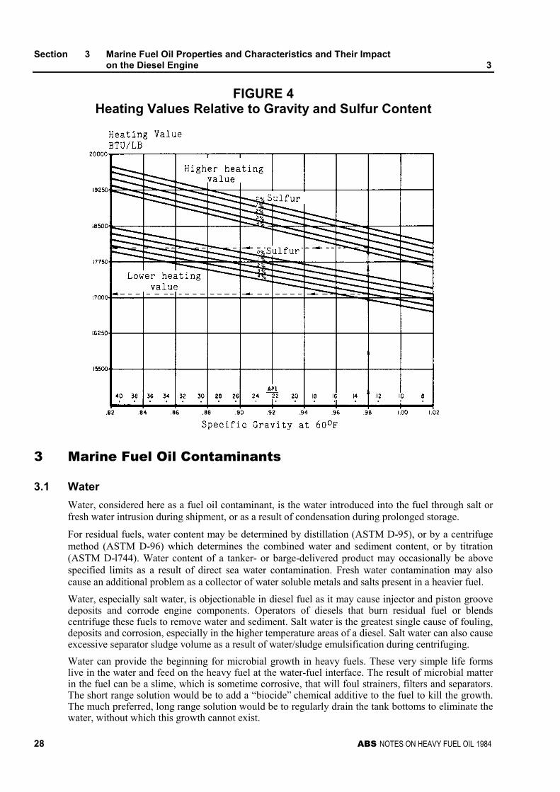
The specific gravity of a fuel oil is a reflection of its heating value. The heating value is determinedprimarily by the carbon/hydrogen ratio; as the carbon/hydrogen ratio increases, the specific gravitywill increase and the heating value will decrease. Section 3, Figure 3 will give some idea of the effectof the carbon/hydrogen ratio and the various hydrocarbon components on the heating value. Theheating value is also decreased by the presence of sulfur.
The heat contained in a fuel, or its heating value (BTU/lb), is primarily affected by changes in aspecific (or API) gravity and its sulfur content in percent by weight. As the gravity of the oilincreases, the ratio of carbon to hydrogen increases, as well as the sulfur content. The result is thatthere is less hydrogen with its high heating value available per pound, and a consequent decrease inheat released during combustion. From a performance viewpoint, this change in heat content is

Section 3 Marine Fuel Oil Properties and Characteristics and Their Impacton the Diesel Engine 3
ABS NOTES ON HEAVY FUEL OIL 1984 27
indicated by an increased brake specific fuel rate in pounds per brake horsepower-hour and, to a veryslight degree, by a decrease in overall engine efficiency, as more fuel with a lower heat content mustbe burned for a fixed power output.
Operationally, at a fixed power, these changes usually can be correlated with such parameters asincreased cylinder exhaust temperatures and increased firing pressures when burning a highergravity/sulfur content fuel. Generally, at constant load, the changes in engine performance due tooperation on higher gravity, lower heat content fuels are relatively small. It is in the area of enginecondition and related factors such as the amount and frequency of required maintenance that operationwith higher gravity and sulfur content fuels will have its greatest impact.
Section 3, Figure 4 presents a graphic relationship of higher and lower heating value sulfur contentand API and specific gravities for marine fuels.
FIGURE 3Relationship between Carbon/Hydrogen Ratio and Gross Heating Value
and Carbon Atoms
Section 3 Marine Fuel Oil Properties and Characteristics and Their Impacton the Diesel Engine 3
28 ABS NOTES ON HEAVY FUEL OIL 1984
FIGURE 4Heating Values Relative to Gravity and Sulfur Content
3 Marine Fuel Oil Contaminants
3.1 Water
Water, considered here as a fuel oil contaminant, is the water introduced into the fuel through salt orfresh water intrusion during shipment, or as a result of condensation during prolonged storage.
For residual fuels, water content may be determined by distillation (ASTM D-95), or by a centrifugemethod (ASTM D-96) which determines the combined water and sediment content, or by titration(ASTM D-l744). Water content of a tanker- or barge-delivered product may occasionally be abovespecified limits as a result of direct sea water contamination. Fresh water contamination may alsocause an additional problem as a collector of water soluble metals and salts present in a heavier fuel.
Water, especially salt water, is objectionable in diesel fuel as it may cause injector and piston groovedeposits and corrode engine components. Operators of diesels that burn residual fuel or blendscentrifuge these fuels to remove water and sediment. Salt water is the greatest single cause of fouling,deposits and corrosion, especially in the higher temperature areas of a diesel. Salt water can also causeexcessive separator sludge volume as a result of water/sludge emulsification during centrifuging.
Water can provide the beginning for microbial growth in heavy fuels. These very simple life formslive in the water and feed on the heavy fuel at the water-fuel interface. The result of microbial matterin the fuel can be a slime, which is sometime corrosive, that will foul strainers, filters and separators.The short range solution would be to add a “biocide” chemical additive to the fuel to kill the growth.The much preferred, long range solution would be to regularly drain the tank bottoms to eliminate thewater, without which this growth cannot exist.
Section 3 Marine Fuel Oil Properties and Characteristics and Their Impacton the Diesel Engine 3
ABS NOTES ON HEAVY FUEL OIL 1984 29
3.3 Sodium (Na)
Sodium is an alkaline, metallic element that is found in the combined form of common salt, NaCl. It isextremely active chemically. The sodium found in fuel can come from several sources. But most of itis a direct result of storing and handling procedures from the time the fuel leaves the refinery until it isdelivered to bunkers. Salt water contamination in barges used to transport the fuel is not uncommon.To some extent, even salt air condensation in fuel tanks contributes to the overall sodium content.
Regardless of the manner of contamination, sodium in fuel is usually water soluble and can, therefore,be removed with the centrifugal separator.
Sodium acts as a paste (flux) for vanadium slag. When unfavorable quantities of vanadium andsodium are present in a fuel they react at combustion temperatures to form (eutectic) compounds withash melting points within operating temperatures. In molten form sodium/vanadium ash can corrodealloy steels, and when this condition is allowed to persist unchecked, high temperature corrosion,overheating, and eventual burning away of exhaust valves, valve faces, and piston crowns is notuncommon. This sodium/vanadium ratio and its relationship to ash melting temperature are shown inSection 3, Figure 5.
The chief corrosive constituents in heavy fuel, oil ash formed during combustion are vanadiumpentoxide, sodium sulphate, and other complex forms of these primary compounds. The chemicalnature of these compounds and their interaction with steel surfaces on exhaust valve seats are of realconcern, as the relatively low melting points of most of these compounds make them very corrosive atnormal engine exhaust temperatures. The thickness of the various oxide layers depends on thetemperature and the exhaust gas composition. In their molten states, the vanadium-sodium-sulfurcompounds also act to dissolve the exhaust valve surface ferric oxide (Fe203) layer, thus exposing theunderlying steel surface to further oxidation attack and subsequent erosion.
The oxidation attack takes place by two mechanisms: gas phase oxidation and liquid phase oxidation.In the gas phase oxidation, the high temperature oxygen-containing exhaust gases react with steel toform oxides. Liquid phase oxidation (corrosion) takes place when molten sulfates and pyrosulfates inthe exhaust gases deposit on valve surfaces. In extreme situations, similar sodium/vanadium ashcorrosion attack can also occur downstream of the exhaust valves in the turbocharger exhaust gasturbine and blading.
3.5 Sediment
Sediment is another contaminant which finds its way into marine bunkers. Rust, scale, weld slag, dirtand other debris can be introduced in storage or in pipeline or barge transport. The majority of thissediment can be removed by settling, straining or filtration, or centrifuging in the shipboard fuel oilsystem.
As the specific gravity and the viscosity of fuel oils increase, the sediment level, which originatesprimarily from transport and storage contamination, will increase as a result of a slowing of thenatural settlement process. As both the water and sediment content of heavy fuel oil increase, theusable energy in the fuel decreases. Usually, if sediment (and water) exceed one percent (1%), mostoil suppliers will adjust bunkered fuel cost to compensate the buyer. However, since sediment (andwater) contamination frequently occur during storage and fuel transport over water, the buyer mustaccurately and continuously sample the fuel oil during bunkering to obtain a representative bunkersample to be assured he is getting what he is paying for. Sediment (and water) can be settled out to alarge degree during heated storage. However, as the specific gravity of heavy fuel oil approaches thatof water, the settling process becomes less and less effective. The effectiveness ofpurification/clarification treatment also is reduced. Sediment removal is essential to reduce high ashor particulate contamination of a fuel since both can contribute to increased deposits, corrosion orabrasive wear.

Section 3 Marine Fuel Oil Properties and Characteristics and Their Impacton the Diesel Engine 3
30 ABS NOTES ON HEAVY FUEL OIL 1984
FIGURE 5Sodium-Vanadium Phase Diagram
3.7 Alumina/Silica
Hard, abrasive particles, such as alumina/silica catalyst carry-over, originate in the refinery when thispowdered catalyst is added to the charge stock of a fluidic catalytic cracking (F.C.C.) unit. Due toerosion and fracture, some of the catalyst is not recovered but is carried over with the bottoms fromthe F.C.C. unit. Larger sized catalyst particles, greater than ten (10) microns, also can be carried overif there is a defect in the catalyst removal equipment (such as cyclone separators), if there is an upsetin the operation of the F.C.C. unit, or if the heavy (low API gravity) bottoms (containing catalystparticles) are not permitted sufficient time to settle-out in heated storage (when this method is used tocontrol catalyst carry-over).
It is also possible to contaminate a clean marine residual fuel oil with catalyst particles duringtransport. For example, if steamship fuel (frequently containing catalyst particles) has beentransported by barge prior to moving a clean heavy fuel oil for a diesel powered ship, the bargebottom sediment will be mixed with the clean fuel oil and will contaminate it.
Section 3 Marine Fuel Oil Properties and Characteristics and Their Impacton the Diesel Engine 3
ABS NOTES ON HEAVY FUEL OIL 1984 31
Because cat-fines are generally small, very hard, and quite abrasive to pumps, atomizers, piston ringsand liners, a number of major diesel engine builders have concluded that thirty parts per million(30 ppm) of alumina in the bunkered fuel oil is the upper limit for successful treatment and engineoperation. The average particle size, as well as the concentration, greatly impacts the wear rate ofengine components. Small sized catalyst particles, in the one to ten (1-10) micron range, typicallycause accelerated wear in injection pumps and injectors and only moderate increases in cylinderassembly wear, such as piston rings, piston grooves, and liners. The larger sized catalyst particles, inthe ten to seventy (10-70) micron range, typically cause very accelerated wear rates in the cylinderassembly area. Accelerated damage can also be expected on injection pump inlet valves, exhaustvalve seating areas, and turbocharger turbine blading. These larger sized particles have beenassociated with catastrophic wear rates.
3.9 Sludge
Sludge is a contaminant that results from the handling, mixing, blending, and pumping of heavy fuelwhile stored at and after it leaves the refinery. Storage tanks, heavy fuel pipe lines, and barging can allcontribute to the sludge. Water contamination of a high asphaltene fuel oil can produce an emulsionduring fuel handling which can contain more than fifty percent (50%) water. Shipboard transferpumps frequently can provide the necessary energy to produce emulsified sludges during normal fueltransfers. These emulsified sludges can cause rapid fouling and shutdown of centrifugal purifiers andclogging of strainers and filters in the fuel oil system, and rapid fouling if burned in the engine.
3.11 Fibers
Fiber contamination can cause significant problems in fuel handling aboard ship. This type ofcontamination usually occurs during transport and storage. Fibers can plug suction strainers protectingpumps within minutes of initial operation. Whereas cleaning strainers is not a difficult task, thefrequency of cleaning and the need for round-the-clock attention generally create problems. Acentrifuge normally is ineffective in removing oil soaked fibers because they have the same density asthe oil being purified. Hence, downstream manual or auto-strainers and fine filters can be expected toclog in a short period of time and continue to clog frequently until the entire amount of a fiber-contaminated fuel has been consumed or removed.
3.13 Oxidation Products
This form of contamination is the result of the marine residual fuel aging, either before or after it isbunkered. Residual fuels are not stable for long periods of time at elevated storage temperatures. Theelapsed time from the refinery to use onboard, ideally, should be less than three (3) months. Further, itis anticipated that future residual fuels resulting from more intense secondary processing will be evenless stable. Heated heavy fuels, stored in uncoated steel tanks and exposed to air (oxygen) oxidize andpolymerize with time. The resultant sludges, gums and resins will initially form in solution and thenagglomerate and settle or adhere to the tank’s surfaces. Also, as heavy fuels age, their shipboardconditioning and treatment become more difficult. In the extreme, the diesel engine’s combustionprocess can deteriorate causing increased fouling, deposits and corrosion as a result of burning suchpartially oxidized older fuel oils.
Generally, residual fuel oils should not be bunkered and utilized as ballast, trim, or held in reserve forextended periods of time. The oldest fuel on the ship should be burned first to prevent any heavy fueloil from aging beyond three (3) months from its bunkering date.

ABS NOTES ON HEAVY FUEL OIL 1984 33
S E C T I O N 4 Fuel Sampling and Analysis
CONTENTS1 Sampling Procedures............................................................ 36
3 Shoreside Analysis ............................................................... 37
5 Shipboard Analyses .............................................................. 37
7 Fuel Specifications and Standards ...................................... 38
FIGURE 1 Typical Sample Connection ...................................... 36

ABS NOTES ON HEAVY FUEL OIL 1984 35
S E C T I O N 4 Fuel Sampling and Analysis
Characteristic properties and contaminants may vary widely in heavy fuel oil, even though traditionalcriteria of viscosity, specific gravity and flash point may appear as standard for a given fuel grade.This inconsistency between accepted criteria and actual properties and high contaminant levels canmask the fact that fuel received is of a quality which can increase overall engine wear, causepremature engine component failures, and significantly raise overall maintenance costs. Theincreasing uncertainty as to marine fuel quality has made the onboard sampling and shipboard andshoreside analysis of a fuel’s physical characteristics necessary to ensure that shipboard fuel treatmentand fuel conditioning equipment can be properly adjusted and maintained to secure efficient dieselengine operation and extended operating life.
The characteristics of heavy fuel oil of importance to the user have been reviewed in previoussections. The traditional criteria of viscosity, specific gravity and flash point no longer yield sufficientinformation to the user as other important characteristics or contamination levels must be known tosafeguard the machinery and ensure proper utilization of the fuel.
To summarize, the properties of interest are:
Density (specific gravity)
Viscosity
Upper pour point
Conradson Carbon Residue
Ash
Water
Sulfur
Vanadium
Aluminum
Silicon
Sodium
Sediment
Asphaltenes
Compatibility
Heating Value
The accurate determination of these characteristics is best performed by a shoreside laboratoryexperienced and skilled in the art of heavy fuel oil analysis. In addition, shipboard test kits areavailable which permit some of these tests to be performed on a continuing basis. Such tests are usefulwhen there is any doubt that samples previously tested are really representative of the fuel being usedat any given time.
Section 4 Fuel Sampling and Analysis 4
36 ABS NOTES ON HEAVY FUEL OIL 1984
1 Sampling Procedures
Prior to testing, it is necessary to obtain a representative sample of the fuel oil as it is being deliveredonboard the vessel.
The fuel analysis will be of value only if it is representative of the bunkers actually loaded onboardand, for this reason, the taking of the sample is of greatest importance. It should be realized that thesample which is sent to the laboratory is only a tiny fraction of actual bunkers loaded and, therefore, itis most important that all containers and other apparatus used be clean and that sampling connectionsbe flushed through before sampling is started. It is also important that sampling be continuedthroughout the entire bunkering period, as the quality may change, due to stratification within thebunkering barge or changes in the blending ratios.
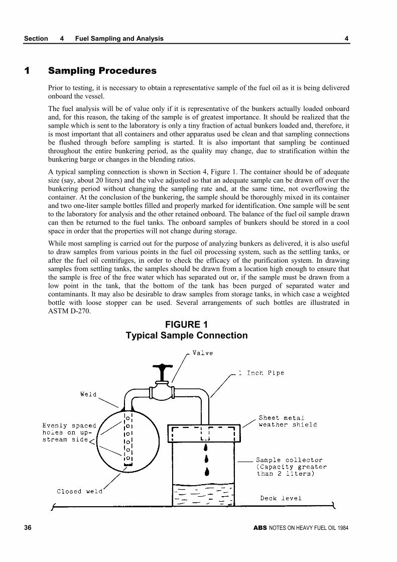
A typical sampling connection is shown in Section 4, Figure 1. The container should be of adequatesize (say, about 20 liters) and the valve adjusted so that an adequate sample can be drawn off over thebunkering period without changing the sampling rate and, at the same time, not overflowing thecontainer. At the conclusion of the bunkering, the sample should be thoroughly mixed in its containerand two one-liter sample bottles filled and properly marked for identification. One sample will be sentto the laboratory for analysis and the other retained onboard. The balance of the fuel oil sample drawncan then be returned to the fuel tanks. The onboard samples of bunkers should be stored in a coolspace in order that the properties will not change during storage.
While most sampling is carried out for the purpose of analyzing bunkers as delivered, it is also usefulto draw samples from various points in the fuel oil processing system, such as the settling tanks, orafter the fuel oil centrifuges, in order to check the efficacy of the purification system. In drawingsamples from settling tanks, the samples should be drawn from a location high enough to ensure thatthe sample is free of the free water which has separated out or, if the sample must be drawn from alow point in the tank, that the bottom of the tank has been purged of separated water andcontaminants. It may also be desirable to draw samples from storage tanks, in which case a weightedbottle with loose stopper can be used. Several arrangements of such bottles are illustrated inASTM D-270.
FIGURE 1Typical Sample Connection
Section 4 Fuel Sampling and Analysis 4
ABS NOTES ON HEAVY FUEL OIL 1984 37
In all cases, when samples are taken for shoreside analysis, it is good practice to take two samples ateach sample location and to retain one sample onboard. Should any questions arise as to the findings,a back-up sample is then available for confirmatory testing. It is also most important that all pertinentinformation relative to each sample, such as the ship’s name, fuel oil supplier, date, specified grade,sample locations, etc., should be recorded and attached to the sample container.
At all times in the taking of samples, care must be exercised to protect the crew from contact with hotoil, pipes or tanks, and exposure to petroleum vapors. Additionally, it should not be assumed thatheavy fuel oil is not capable of releasing potentially explosive vapors; many fuels as bunkered areblended with lighter stocks in order to provide the specified viscosity and, in many cases, the flashpoint is not reported, or is in error.
3 Shoreside Analysis
The benefit of a complete and accurate shoreside analysis can be summarized as follows:
i) Confirmation that bunkers as received meet purchase specifications (or do not meet specs, asthe case may be).
ii) Provides warning of contaminant levels, incompatibility, excessive water content, etc.
iii) Enables engineers to adopt suitable strategies for proper utilization of the fuel.
iv) Provides permanent independent third-party report (analysis) of fuel oil received and enablesowner to claim against bunker supplier in case of failure to meet purchase specifications or incase of delivery of unmarketable product.
v) Shoreside laboratory will normally alert owner to any unusual or potentially damagingcharacteristics or fuel oil and will suggest proper countervailing strategies.
The single most important constraint in this process is time. It is highly desirable to have the results ofthe shoreside analysis available to the owner (and, of course, the ship’s engineer) before the fuel is tobe used. As will be discussed in Section 5, modern practice requires that new bunkers be segregatedfrom existing bunkers to the greatest extent possible. The efficient shoreside laboratory should be ableto complete a sample analysis and transmit telex advice of results within 24 hours of receipt ofsample, and the proper management of the dispatch and routing of the sample is of great importance.In general, it is preferable to use one shoreside laboratory using known and accepted analyticaltechniques rather than a variety of laboratories around the world. A laboratory located on the MiddleAtlantic (East Coast) region of the United States is particularly favorably located with respect toairline service, and experienced courier services can provide rapid custom clearance and sampledelivery. By using a single laboratory, the results from all samples analyzed can be consideredcomparable, which will not be the case for analyses from different laboratories located in various partsof the world.
5 Shipboard Analyses
Shipboard fuel testing kits provide a means for the ship’s engineering personnel to perform several ofthe tests previously discussed. The kits are of moderate cost and are generally arranged to provide forthe following tests:
Density (specific gravity)
Pour Point
Viscosity
Water content
Salt water
Section 4 Fuel Sampling and Analysis 4
38 ABS NOTES ON HEAVY FUEL OIL 1984
Compatibility
Catalyst particles
Sludge/Wax determination
All of the above can be performed with relative ease and, although the same accuracy or reliabilityexpected from shoreside analyses cannot be attained, they are useful for adjustment of purifyingequipment, assuring proper temperature for required viscosity, quick and easy checks on bunkerreceipts, etc.
7 Fuel Specifications and Standards
Two documents are available to the owner for use in specifying fuel quality. The first is the BritishStandards Institute BSMA 100:1982, “Petroleum Fuels for Marine Oil Engines and Boilers,” and theother is the CIMAC (International Congress on Combustion Engines, Congress International desMachines a Combustion) “Requirements for Specifications of Intermediate Marine Fuels.” Inaddition, the ISO (International Organization for Standardization) has a draft standard in preparation.Both the British Standard and the CIMAC document are outgrowths of the ISO work.
It is important to recognize that the BSI standard is a supply standard; i.e., it is based on what may beavailable rather than what is required; the CIMAC recommendations represent the work of therepresentatives of the engine builders and are intended to establish certain quality categories suitablefor different types of engines. According to the chairman of the CIMAC Working Group “FutureFuels,” the engine manufacturers have agreed to base their fuel specifications on the CIMACrecommendations although, in individual cases, they may be amplified according to type of engine.
In all cases, the owner should give close attention to the engine builder’s specifications, as these maybe an issue in any engine damage warranty claims which may be related to fuel quality.
ABS NOTES ON HEAVY FUEL OIL 1984 39
S E C T I O N 5 Shipboard Fuel Handling andTreatment for Diesel Engines
CONTENTS1 Marine Diesel Oil Systems .................................................... 41
1.1 Fill, Transfer, Storage and Purification System...................... 41
1.3 Service System ...................................................................... 42
3 Heavy Fuel Oil Systems ........................................................ 43
3.1 Fill, Transfer, Storage and Purification System...................... 43
3.3 Transfer Pump Suction Strainers ........................................... 44
3.5 Transfer Pump........................................................................ 44
3.7 Settling Tanks......................................................................... 45
3.9 Separator Pump Suction Strainers......................................... 45
3.11 Separator Heaters .................................................................. 45
3.13 Separators .............................................................................. 45
3.15 Filters...................................................................................... 47
3.17 Service System ...................................................................... 47
3.19 Service Tank .......................................................................... 47
3.21 Mixing Tank ............................................................................ 48
3.23 Service Pump Suction Strainers............................................. 48
3.25 Fuel Oil Service Pumps.......................................................... 49
3.27 Fuel Oil Service Heaters ........................................................ 49
3.29 Viscometer.............................................................................. 49
3.31 Final Filter............................................................................... 49
5 Operating Guidelines and Recommendations .................... 49
5.1 General Fuel Handling ........................................................... 49
5.3 Centrifugal Separator ............................................................. 50
5.5 Preheating and Combustion................................................... 51
7 Recommended Procedures for the Onboard Treatmentof Problem Fuels: Very Poor Quality or HighlyContaminated Fuel Oils ........................................................ 51
7.1 High Water and Sediment ...................................................... 51
7.3 High Catalyst Particle and Ash Content ................................. 52
7.5 High Specific Gravity .............................................................. 53
7.7 High Vanadium, Nickel and Lead........................................... 54
7.9 High Conradson Carbon Content/High AsphalteneContent ................................................................................... 55
TABLE 1 Fuel Property/contaminant Problem ResolutionMatrix ..........................................................................58
FIGURE 1 Typical Diesel Oil Fill, Transfer, Storage andPurification System....................................................42
FIGURE 2 Typical Diesel Oil Service System.............................43
FIGURE 3 Typical Heavy Fuel Oil Fill, Transfer, Storage, andPurification System....................................................44
FIGURE 4 Typical Heavy Fuel Oil Service System ....................48
FIGURE 5 Typical Purifier/Purifier System for High Water andSediment (1 to 2%) .....................................................52
FIGURE 6 Typical Centrifuge Configuration for High Ash(0.20 to 0.50% wt.) High Catalytic Fines (60 ppm to300 ppm Total) ............................................................53
FIGURE 7 Typical Clarifier/Clarifier System for High SpecificGravity (0.991 to 1.006) Fuel Oils...............................54
FIGURE 8 Typical Additive Injection System for HighConcentrations of Oil Soluble Heavy Metals............56
FIGURE 9 Typical Water in Oil Emulsification/Homogenizationfor High Conradson Carbon Content Fuels (15 to22% wt.).......................................................................57
ABS NOTES ON HEAVY FUEL OIL 1984 41
S E C T I O N 5 Shipboard Fuel Handling andTreatment for Diesel Engines
The ship owner’s first point of active fuel control and handling begins at the ship’s bunkeringconnection. The ultimate movement, storage, inventory and final processing of the fuel is theresponsibility of the ship’s operating personnel. Pre-planned and prudent execution of fuel oilmanagement within the ship’s transfer and processing systems will minimize the potential for creatingunworkable fuel compatibility and combustion problems.
1 Marine Diesel Oil Systems
1.1 Fill, Transfer, Storage and Purification System
Marine diesel oil (MDO) is a middle distillate fuel oil which can contain traces to ten percent (10%)or more residual fuel oil from transportation contamination and/or heavy fuel oil blending.
Section 5, Figure 1 illustrates a basic diesel oil fill, transfer, storage and purification system. Thediesel oil is bunkered at a dedicated deck connection for transfer and distribution to the ship’s storagetanks. A sample cock is provided at the deck connection to permit obtaining fuel samples during thebunkering process.
Diesel oil is transferred from the storage tanks by means of a transfer pump and/or a purifier mountedpump. Single stage purification is typically operated at 100% throughput. However, a reduction inthroughput to 60-70% of rated capacity may be made when purifying the more contaminated dieseloils. The only heating requirement for diesel oil is a preheater for purification purposes.
Storage tank stripping connections should be provided to permit pumping the tank contents to anyother storage tank, the purifier, or a sludge tank.
The basic system illustrated in Section 5, Figure 1 provides the following capabilities:
i) Diesel oil sampling while bunkering
ii) Diesel oil transfer from storage to service tank(s) by way of the purifier system
iii) Diesel oil transfer from any storage tank to any other storage tank, or directly to the servicetank
iv) Diesel oil supplied to the emergency diesel generator by either the transfer pump or thepurifier
v) Diesel oil service tank bottom drains directly to the sludge tank
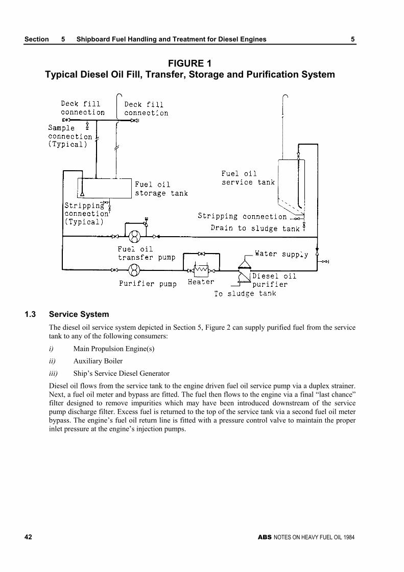
Section 5 Shipboard Fuel Handling and Treatment for Diesel Engines 5
42 ABS NOTES ON HEAVY FUEL OIL 1984
FIGURE 1Typical Diesel Oil Fill, Transfer, Storage and Purification System
1.3 Service System
The diesel oil service system depicted in Section 5, Figure 2 can supply purified fuel from the servicetank to any of the following consumers:
i) Main Propulsion Engine(s)
ii) Auxiliary Boiler
iii) Ship’s Service Diesel Generator
Diesel oil flows from the service tank to the engine driven fuel oil service pump via a duplex strainer.Next, a fuel oil meter and bypass are fitted. The fuel then flows to the engine via a final “last chance”filter designed to remove impurities which may have been introduced downstream of the servicepump discharge filter. Excess fuel is returned to the top of the service tank via a second fuel oil meterbypass. The engine’s fuel oil return line is fitted with a pressure control valve to maintain the properinlet pressure at the engine’s injection pumps.
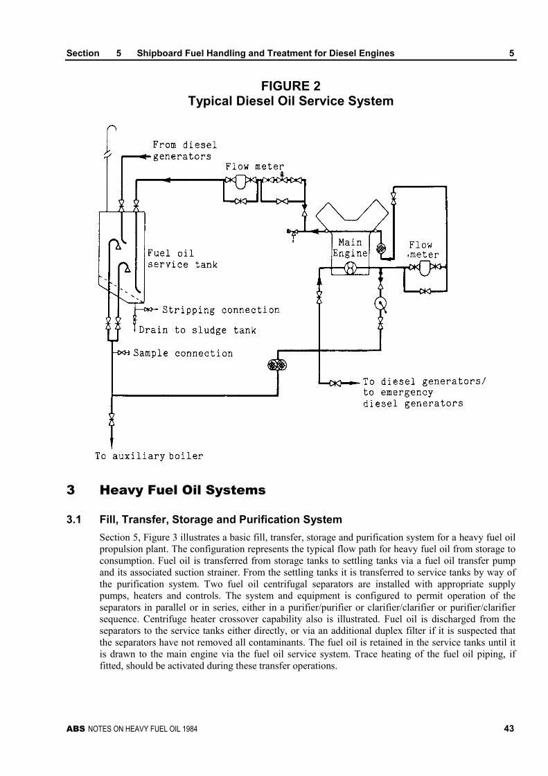
Section 5 Shipboard Fuel Handling and Treatment for Diesel Engines 5
ABS NOTES ON HEAVY FUEL OIL 1984 43
FIGURE 2Typical Diesel Oil Service System
3 Heavy Fuel Oil Systems
3.1 Fill, Transfer, Storage and Purification System
Section 5, Figure 3 illustrates a basic fill, transfer, storage and purification system for a heavy fuel oilpropulsion plant. The configuration represents the typical flow path for heavy fuel oil from storage toconsumption. Fuel oil is transferred from storage tanks to settling tanks via a fuel oil transfer pumpand its associated suction strainer. From the settling tanks it is transferred to service tanks by way ofthe purification system. Two fuel oil centrifugal separators are installed with appropriate supplypumps, heaters and controls. The system and equipment is configured to permit operation of theseparators in parallel or in series, either in a purifier/purifier or clarifier/clarifier or purifier/clarifiersequence. Centrifuge heater crossover capability also is illustrated. Fuel oil is discharged from theseparators to the service tanks either directly, or via an additional duplex filter if it is suspected thatthe separators have not removed all contaminants. The fuel oil is retained in the service tanks until itis drawn to the main engine via the fuel oil service system. Trace heating of the fuel oil piping, iffitted, should be activated during these transfer operations.
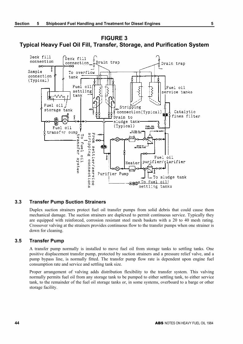
Section 5 Shipboard Fuel Handling and Treatment for Diesel Engines 5
44 ABS NOTES ON HEAVY FUEL OIL 1984
FIGURE 3Typical Heavy Fuel Oil Fill, Transfer, Storage, and Purification System
3.3 Transfer Pump Suction Strainers
Duplex suction strainers protect fuel oil transfer pumps from solid debris that could cause themmechanical damage. The suction strainers are duplexed to permit continuous service. Typically theyare equipped with reinforced, corrosion resistant steel mesh baskets with a 20 to 40 mesh rating.Crossover valving at the strainers provides continuous flow to the transfer pumps when one strainer isdown for cleaning.
3.5 Transfer Pump
A transfer pump normally is installed to move fuel oil from storage tanks to settling tanks. Onepositive displacement transfer pump, protected by suction strainers and a pressure relief valve, and apump bypass line, is normally fitted. The transfer pump flow rate is dependent upon engine fuelconsumption rate and service and settling tank size.
Proper arrangement of valving adds distribution flexibility to the transfer system. This valvingnormally permits fuel oil from any storage tank to be pumped to either settling tank, to either servicetank, to the remainder of the fuel oil storage tanks or, in some systems, overboard to a barge or otherstorage facility.
Section 5 Shipboard Fuel Handling and Treatment for Diesel Engines 5
ABS NOTES ON HEAVY FUEL OIL 1984 45
3.7 Settling Tanks
Settling tanks have several important functions in the proper treatment of heavy fuel oil. They providea settling function for gross water and solids, a heating function, a deaeration function, and a thermalstabilizing function. Ships’ settling tanks are designed to accept fuel oils with a 60 degrees Centigrademinimum flash point. The two settling tank concept is the most common arrangement, with each tankholding up to one day’s required fuel oil supply at full power. More conservative designs haveincreased settling tank residence time up to four (4) days per tank. Normally, one tank is being filledfrom the transfer system and holding fuel while the other tank is supplying fuel to service tanks viaheaters and separators. As soon as a settling tank is filled, it is heated to 72 degrees Centigrade, or6 degrees Centigrade below the flash point, whichever is lower. From a safety standpoint, fuel oilsmust never be heated in ships’ tankage at or above the fuel’s flash point. In a diesel propulsionsystem, once tank contents have been heated to the selected temperature, settling tank heat should besecured and the fuel allowed to settle undisturbed for as long as possible. The tanks should beinsulated where possible to reduce heat loss. It is important to secure the settling tank heat sourceonce its contents are up to temperature, because continuous heating will produce thermal currentswithin the tank which interfere with the settling process (Stokes’ law). Because of constant heat lossfrom a settling tank, it may be necessary to reactivate the tank heating system periodically in order tomaintain its contents at 60 degrees Centigrade or better.
Settling tanks should have bottom drains for water and sludge stripping. And, water and sludge shouldbe removed on a regular basis by means of these drains.
3.9 Separator Pump Suction Strainers
Duplex suction strainers are used to protect separator service pumps from debris in the delivered fuel.The 20 to 40 mesh baskets should be reinforced, corrosion resistant, and protected by a differentialpressure system. The strainers should have non-interrupting, crossover valving to provide continuousflow to the purifier service pumps on one strainer while cleaning the other.
3.11 Separator Heaters
Separator heaters are horizontal shell and tube or plate type units. Each heater normally services oneseparator and is designed to provide an oil outlet temperature of 98 degrees Centigrade. Thetemperature control circuit utilizes a temperature probe and transmitter, a steam control valve andsteam drain trap. Heaters are piped for one or two heater operation and are fitted with suitableisolation valving for single unit servicing. Successful separator operation dictates that these heatersand associated control circuits supply heavy fuel oils at the required temperature for reliable, efficientseparator operation.
3.13 Separators
Two properly sized, properly adjusted, correctly operated, self-cleaning separators are considered tobe necessary for any reliable, shipboard heavy fuel treatment system operating on today’s heavy fueloils, Whereas separator systems are a necessity, these basic units cannot supply total systemprotection under all circumstances. Other systems, discussed in 2/7, may be necessary to supplement,but not replace, these basic units.
Efficient and consistent separator operation depends on an understanding of and the application of thebasic principles of fuel handling, treating and conditioning:
i) The separator is the first major stage of fuel treatment
ii) To treat degraded fuel oils, supplementary systems in addition to the separators may berequired
Section 5 Shipboard Fuel Handling and Treatment for Diesel Engines 5
46 ABS NOTES ON HEAVY FUEL OIL 1984
iii) The following heavy fuel oil properties should be known to achieve proper adjustment andoperation of separators:
Viscosity
Specific Gravity (or API Gravity)
Compatibility of fuel oil
Water content
Ash content
Other contaminant content (such as BS&W)
iv) All installed heavy fuel oil separators should be online and operated continuously. The onlyacceptable reason for not operating a unit is during manual cleaning or overhaul.
v) Single separator flow rate (for series operation) or combined separator flow rate (for paralleloperation) should not exceed the existing engine fuel consumption rate by more than tenpercent (10%)
vi) Each time a new settling tank is pumped, a specific gravity check of the settling tank shouldbe made and the separator gravity disc checked and changed if necessary.
vii) Each separator should have all parts necessary to operate as a purifier and as a clarifier, aswell as a complete set of tools and spares
The centrifugal separator is the foundation of the total shipboard fuel treatment system. Its efficientoperation is critical to the safety and reliability of the main and auxiliary propulsion equipment. Itsoperation must be thoroughly understood by the shipboard engineers so that they can immediatelytroubleshoot heavy fuel oil problems as they occur. A treatment problem cannot wait until the nextport. Major main engine damage can result quickly from lack of proper treatment of degraded fuel oil.Some basic situations which can cause separators to operate below maximum efficiency, or not workat all, are:
i) Incorrect fuel handling before the centrifuge
ii) Unstable flow
iii) Incorrect flow, (usually too high a flow)
iv) Unstable temperature
v) Incorrect temperature
vi) Incorrect positioning of the water/oil interface, thereby inhibiting the correct flow of oilthrough all discs, (usually caused by incorrect gravity data and/or choice of an incorrectgravity disc)
vii) Overfilling of sludge space caused by extended intervals between desludging, or incompatibleheavy fuel oils with higher than normal sludge deposits
The following observations are indicative of inefficient or incorrect separator operation which may becaused by changes in the fuel oil characteristics. A separator which breaks the water seal afterexperiencing balanced operation may be the result of increased fuel density, increased viscosity,increased flow rate, or a decrease in temperature. If the oil/water interface moves towards the axis ofthe bowl to give poor fuel separation or water carryover into the oil phase, the potential causes may bedecreased flow rate, or increased temperature. If the separator failure occurs because of anuncontrollable fuel oil characteristic, such as increased density or viscosity, the gravity disc should bechanged to achieve efficient operation. It also may be necessary to decrease throughput to effectivelypurify higher viscosity fuels.
Section 5 Shipboard Fuel Handling and Treatment for Diesel Engines 5
ABS NOTES ON HEAVY FUEL OIL 1984 47
3.15 Filters
A filtration system before the service tank is recommended and is currently in use in many modernshipboard fuel treating and conditioning systems. The higher ash, solids, and catalyst particle contentbeing found more frequently in heavy fuels make such an installation prudent. A properly designedfiltration system would positively control solids that can damage high pressure pumps, injectionsystems, and the cylinder bores of diesel engines. Under normal operating conditions, properlydesigned and operated filtration systems can provide positive protection with 2000-3000 hourintervals between filter element replacement.
Because heavy fuel oils may contain more sediment, dirt, ash and catalyst particles, the separatorsystem, preferably operating in series, can provide a sizeable initial reduction in these solids, but notalways enough to prevent an increase in engine wear rates. The remainder of the small solids, as wellas a small percentage of large particles, can be effectively stopped by a five (5) micron (nominal),replaceable element, depth type, filtration system. The filtration units should be designed to preventbypassing of fuel around the end sealing cups. The filter housing should be equipped with a bottomwater drain, an air vent and a differential pressure gauge correlation to indicate the pressure dropacross the filter so that an accurate determination of filter element replacement requirement can bemade.
In addition to solids, trace quantities of free water carried over from the separators also are removedby these filters. Whereas removing trace water may seem unimportant, shipboard experience hasshown that injection pump life can increase by as much as 100 percent (100%) by its elimination. Thefilter water sumps should be drained daily to prevent water from rising above the sump level and“wetting” the filter elements.
3.17 Service System
Section 5, Figure 4 illustrates a typical heavy fuel oil service system for a diesel propulsion system.The fuel oil service system forwards the oil from the respective service tanks to the main propulsionengine(s), auxiliary diesel generator(s) and/or auxiliary boiler.
Fuel oil flows from the service tank via the fuel changeover valve to a mixing tank. From the mixingtank, one of two booster pumps delivers the fuel through a fuel oil service heater, a viscositycontroller, and a final filter to the main engine fuel pumps. Excess oil is normally returned to themixing tank or, if desired, to the service tank through a changeover valve.
3.19 Service Tank
Service tanks, or day tanks, have a very important function in the overall treatment of heavy fuel oilfor diesel engines. They provide a final settling function for water and solids, a heating function and athermal stabilizing function. The settling function is primarily a backup in the event of a performancefailure of the separators and/or during a by-pass of the filtration system. Two service tanks arenormally provided.
While one service tank is supplying fuel oil to the system, the other is receiving fuel oil conditionedthrough the separator and filtration systems. The tanks normally have high and low suction lines withdownturned diffusers. The cleanest fuel oil is available from the upper (high) suction. Therefore itshould be used whenever possible. The service tanks should have bottom drain connections for waterand sludge stripping. The water and sludge from this bottom drain should be removed at regularintervals.
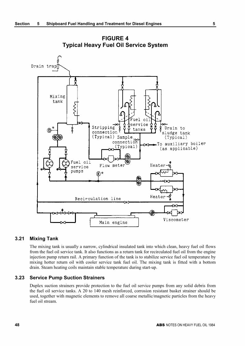
Section 5 Shipboard Fuel Handling and Treatment for Diesel Engines 5
48 ABS NOTES ON HEAVY FUEL OIL 1984
FIGURE 4Typical Heavy Fuel Oil Service System
3.21 Mixing Tank
The mixing tank is usually a narrow, cylindrical insulated tank into which clean, heavy fuel oil flowsfrom the fuel oil service tank. It also functions as a return tank for recirculated fuel oil from the engineinjection pump return rail. A primary function of the tank is to stabilize service fuel oil temperature bymixing hotter return oil with cooler service tank fuel oil. The mixing tank is fitted with a bottomdrain. Steam heating coils maintain stable temperature during start-up.
3.23 Service Pump Suction Strainers
Duplex suction strainers provide protection to the fuel oil service pumps from any solid debris fromthe fuel oil service tanks. A 20 to 140 mesh reinforced, corrosion resistant basket strainer should beused, together with magnetic elements to remove all coarse metallic/magnetic particles from the heavyfuel oil stream.
Section 5 Shipboard Fuel Handling and Treatment for Diesel Engines 5
ABS NOTES ON HEAVY FUEL OIL 1984 49
3.25 Fuel Oil Service Pumps
Two fuel oil service pumps (one standby and one operational) are provided to supply heavy fuel oil tothe downstream service system (service heaters, viscometer, flow meter and main engine). Each fueloil service pump is capable of supplying the total required fuel flow plus an additional margin.
3.27 Fuel Oil Service Heaters
Two fuel oil service, steam heated, shell and tube or plate-type heat exchangers with a capability ofheating heavy fuel oil to 150 degrees Centigrade should be installed. The final fuel oil outlettemperature is controlled by the viscometer. The viscometer continuously provides a viscosity readoutand control signal to the steam control valve regulating the steam flow to the heat exchanger. In thissystem, the viscosity to the diesel engine injectors is held constant even though the fuel oiltemperature might vary slightly. When heating heavy fuel oils to almost 150 degrees centigrade theuse of properly sized, steam heat exchangers will provide the necessary heat without thermallystressing the fuel oil with hot spots which produce coked heaters and cracked fuel.
3.29 Viscometer
The viscometer is a critical component which ensures uniform and accurate viscosity control. Theviscometer constantly samples the heavy fuel oil and produces a signal which is proportional toviscosity. Typical sensors employ calibrated capillary tubes, falling pistons, or vibrating rods.Irrespective of the method of determining viscosity, the viscometer output signal is utilized tomodulate an automatic steam control valve on the fuel oil service heaters. Since the viscometer isconstantly sampling and adjusting the fuel oil heater outlet temperature to maintain a constant presetviscosity, the accuracy of this unit must be checked and calibrated periodically. Experience suggeststhat service once every six (6) months by disassembly and recalibration is prudent. The unit should becarefully installed according to the manufacturer’s recommendations. A valved bypass and isolationvalves also should be provided to allow for service without plant shutdown.
3.31 Final Filter
A duplex, final protection, ten (10) micron filter usually is installed immediately prior to the inlet ofthe fuel injection pumps to protect pump plungers and barrels from any untreated contamination orrandom debris remaining in the fuel. While it may appear that this final filter is not necessary due tothe cleaning and treatment equipment upstream, high pressure diesel injection pumps are verysensitive to minute particles of debris. This material can cause micro-seizures and finally total failureof the pump plunger and barrel.
5 Operating Guidelines and Recommendations
There are a number of observations which lead to recommended procedures and operational changeswhich can improve the efficiency of fuel oil treatment and can reduce unnecessary extra maintenanceon the fuel system and the diesel engine-
For the most part, these procedures can be accomplished with little or no investment of capital funds.The observations and recommended procedures are enumerated in the following:
5.1 General Fuel Handling
i) Marine fuel oil quality is degrading and contamination levels are increasing.
ii) Diesel engines in many instances cannot operate on heavy fuel oils as bunkered.
iii) Viscosity does not define quality. Quality determinations based solely on viscosity aredangerous.
Section 5 Shipboard Fuel Handling and Treatment for Diesel Engines 5
50 ABS NOTES ON HEAVY FUEL OIL 1984
iv) As marine fuel oil quality degrades, the fuel treatment system must carry a greater load toprotect the engine adequately.
v) With degrading fuel quality, the fuel treatment system will be operating closer to the limit ofits capabilities. Less margin for error will exist.
vi) Bunker receipts do not tell the story − sometimes they are wrong − they are always inadequate
vii) Observe delivery oil temperature. High temperatures could mean a waxy fuel is beingsupplied.
viii) Shipboard personnel should take and retain a two-liter sample from the ship’s bunker lineduring each bunkering.
ix) Drain settling and service (day) tank bottoms daily. Note and report gross water discharge.
x) On a regular basis, every six to twelve months, have the viscometer checked and calibrated byfactory service representative.
xi) Simple shipboard testing is necessary to accurately adjust the fuel treatment system and tocheck on system operation.
xii) New bunkers must be segregated in storage, settling, and service tanks, particularly whencompatibility information is not available. Limit the transfer of fuel oil to prevent unwantedmixing.
xiii) Shipboard fuel treatment impacts the performance, operation and maintenance requirementsof a diesel engine.
xiv) It is important to recognize the nature of the deficiencies and contaminants in poor qualityfuel oil as soon as possible after receiving it.
xv) Early recognition and evaluation of the problem properties and early adjustment of the fuel oiltreatment systems to compensate is the only practical way to protect a diesel engine frompotential damage.
xvi) The key to successful operation of ships using fuel of high viscosity and low quality lies ingood engine room practices, together with carefully controlled treatment.
5.3 Centrifugal Separator
i) It is important that the separators be correctly adjusted for the specific gravity of the fuelbeing treated- All fuel oil separators available should be operated continuously. Fuel flow rateand temperature control also are important.
ii) Experience has shown that the correct temperature for centrifuging high viscosity fuels is inthe region of 95 to 98 degrees Centigrade.
iii) If excessive sludging should occur, giving evidence of incompatibility, the fuel should beseparated at the slowest possible rate using purifiers in parallel. When drawing from a fueltank for the first time, it is very important that a careful watch be kept on the purifier for thefirst twelve (12) hours of separation.
iv) When starting a separator, the fuel oil discharge should be returned to the settling tank untilstable efficient operation has been confirmed. Then it is safe to reroute the fuel oil to theservice tank.
v) For most operating situations, series separation is recommended. The purifier backed up bythe clarifier offers the best operation from a water, sediment and sludge removal, and safetyof operation viewpoint.
vi) If the specific gravity of the fuel oil exceeds 0.991, the purifier should be reconfigured as aclarifier and the shoot or sludge discharge cycle decreased to between five (5) and twenty (20)minutes.
Section 5 Shipboard Fuel Handling and Treatment for Diesel Engines 5
ABS NOTES ON HEAVY FUEL OIL 1984 51
vii) Fuel oil flow through a separator can best be controlled by a variable speed motor fitted onthe feed pump supplying the separator. This method is highly recommended over throttling asingle speed feed pump. The approach minimizes formation of troublesome third phase,water-in-oil emulsions that require extra maintenance to manually clean the separator.
5.5 Preheating and Combustion
i) Most engine manufacturers require that fuel should be of a specified viscosity at the fuelpump inlet. Where the viscosity has been altered due to mixing fuel from a different source, itis important to check on the new viscosity both from the point of view of correct separationand from the need to attain the correct level of preheating.
ii) Vessels fitted with automatic viscometers can cope readily with changing viscosity, if theviscometers are regularly maintained and calibrated.
iii) To determine a specific engine’s recommended injection viscosity, consult the enginebuilder’s operating manual.
iv) When burning high viscosity, carbon rich fuels, it is of paramount importance that the correctoperating limits be maintained in the engine, Scavenge air temperature, cooling watertemperature and cylinder oil feed rates must all be carefully monitored and adjusted.
v) In order to cope with the possible problems associated with deterioration in fuel quality, thenormal well-proven standards applicable to good combustion assume ever greater importance,i.e., injector maintenance, cooling temperature control, and scavenge air temperature control.
7 Recommended Procedures for the Onboard Treatment ofProblem Fuels: Very Poor Quality or Highly ContaminatedFuel Oils
Some percentage of fuel oil bunkerings will have a problem in that various fuel properties andcontamination levels will be very poor and will greatly exceed the engine manufacturer’s fuelrequirements. Some operators would suggest that one fuel delivery in every seven liftings has aproblem in meeting extremes in specified characteristics and quality. From another viewpoint, thiswould translate into every ship having a fuel problem at least once every year. An example of thismight be a fuel oil with high water contamination, possibly caused by a leak in the bunker deliverybarge. Recently, the fuel properties that have most frequently exceeded specification are free water,specific gravity and cat fines content The lifting of a problem fuel may never occur for manyoperators, occasionally for some and frequently for others who, because of particular trade routerequirements, must routinely bunker a specific fuel, or from a specific fuel oil supplier, or from aspecific port. To improve the diesel vessel’s capability to tolerate extremes in fuel properties andcontaminants, certain specialized components and subsystems can be installed aboard ship.Additionally, modified operational procedures for existing fuel system components may be used. Thisequipment and related procedures, as they are applied to the more common fuel related problems ofvery poor quality of highly contaminated fuel oils, are described in the following paragraphs.
7.1 High Water and Sediment
High water and sediment levels in heavy fuel oils usually result from extreme contamination intransportation or as a result of an upset in refinery storage operations. To prevent diesel injectionsystem corrosion and cavitation, and/or accelerated bore wear rates, the high water and sediment ratesmust be controlled by the fuel treatment system.
Both separators should be operated in parallel and configured in the purifier mode with both purifiersoperated at all times. The purifier sludge tank stripping and cleaning frequency should be increased as
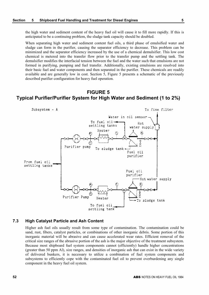
Section 5 Shipboard Fuel Handling and Treatment for Diesel Engines 5
52 ABS NOTES ON HEAVY FUEL OIL 1984
the high water and sediment content of the heavy fuel oil will cause it to fill more rapidly. If this isanticipated to be a continuing problem, the sludge tank capacity should be doubled.
When separating high water and sediment content fuel oils, a third phase of emulsified water andsludge can form in the purifier, causing the separator efficiency to decrease. This problem can beminimized and the separator efficiency increased by the use of a chemical demulsifier. This low costchemical is metered into the transfer flow prior to the transfer pump and the settling tank. Thedemulsifier modifies the interfacial tension between the fuel and the water such that emulsions are notformed in purifying, pumping and fuel transfer. Additionally, existing emulsions are resolved intotheir basic fuel and water components and then separated in the purifier. These chemicals are readilyavailable and are generally low in cost. Section 5, Figure 5 presents a schematic of the previouslydescribed purifier configuration for heavy fuel operation.
FIGURE 5Typical Purifier/Purifier System for High Water and Sediment (1 to 2%)
7.3 High Catalyst Particle and Ash Content
Higher ash fuel oils usually result from some type of contamination. The contamination could besand, rust, fibers, catalyst particles, or combinations of other inorganic debris. Some portion of thisinorganic material will be abrasive and can cause accelerated wear rates. Efficient removal of thecritical size ranges of the abrasive portion of the ash is the major objective of the treatment subsystem.Because most shipboard fuel system components cannot (efficiently) handle higher concentrations(greater than 50 ppm Al), size ranges, and densities of inorganic ash that can exist in the wide varietyof delivered bunkers, it is necessary to utilize a combination of fuel system components andsubsystems to efficiently cope with the contaminated fuel oil to prevent overburdening any singlecomponent in the heavy fuel oil system.
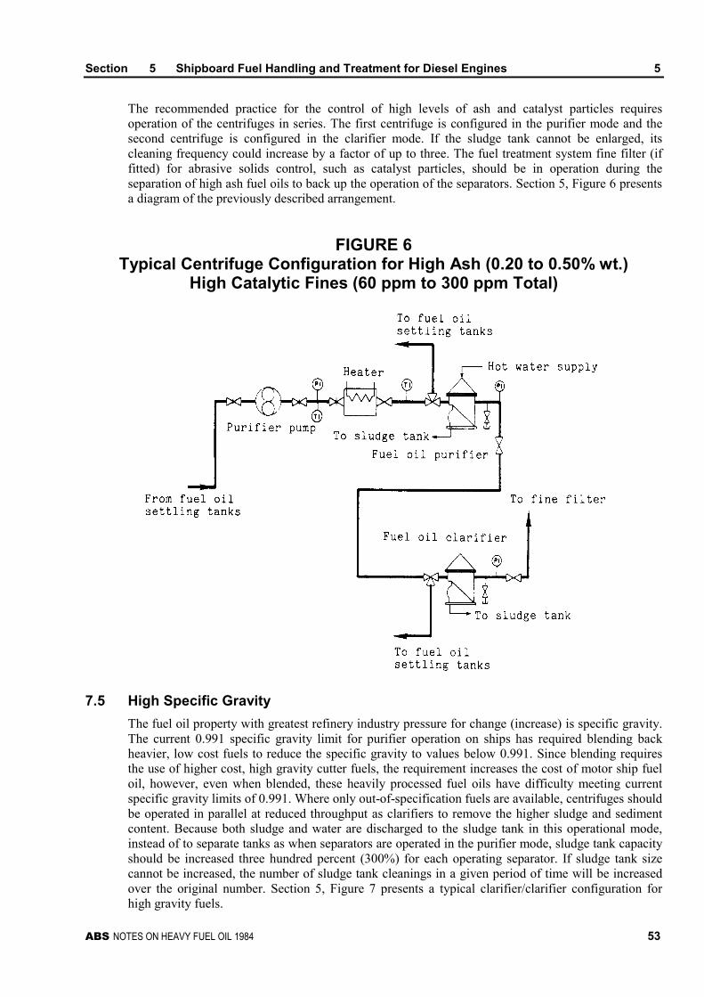
Section 5 Shipboard Fuel Handling and Treatment for Diesel Engines 5
ABS NOTES ON HEAVY FUEL OIL 1984 53
The recommended practice for the control of high levels of ash and catalyst particles requiresoperation of the centrifuges in series. The first centrifuge is configured in the purifier mode and thesecond centrifuge is configured in the clarifier mode. If the sludge tank cannot be enlarged, itscleaning frequency could increase by a factor of up to three. The fuel treatment system fine filter (iffitted) for abrasive solids control, such as catalyst particles, should be in operation during theseparation of high ash fuel oils to back up the operation of the separators. Section 5, Figure 6 presentsa diagram of the previously described arrangement.
FIGURE 6Typical Centrifuge Configuration for High Ash (0.20 to 0.50% wt.)
High Catalytic Fines (60 ppm to 300 ppm Total)
7.5 High Specific Gravity
The fuel oil property with greatest refinery industry pressure for change (increase) is specific gravity.The current 0.991 specific gravity limit for purifier operation on ships has required blending backheavier, low cost fuels to reduce the specific gravity to values below 0.991. Since blending requiresthe use of higher cost, high gravity cutter fuels, the requirement increases the cost of motor ship fueloil, however, even when blended, these heavily processed fuel oils have difficulty meeting currentspecific gravity limits of 0.991. Where only out-of-specification fuels are available, centrifuges shouldbe operated in parallel at reduced throughput as clarifiers to remove the higher sludge and sedimentcontent. Because both sludge and water are discharged to the sludge tank in this operational mode,instead of to separate tanks as when separators are operated in the purifier mode, sludge tank capacityshould be increased three hundred percent (300%) for each operating separator. If sludge tank sizecannot be increased, the number of sludge tank cleanings in a given period of time will be increasedover the original number. Section 5, Figure 7 presents a typical clarifier/clarifier configuration forhigh gravity fuels.

Section 5 Shipboard Fuel Handling and Treatment for Diesel Engines 5
54 ABS NOTES ON HEAVY FUEL OIL 1984
To further improve operation as a clarifier, a water (in fuel oil) monitor is needed and should beplaced downstream from clarifiers, as an indication of the water content of the fuel oil, and to monitorand to initiate the automatic cleaning cycles of the clarifiers. This latter feature can reduceunnecessary cleaning cycles without introducing lower operational efficiencies because of water over-loaded separator bowls.
FIGURE 7Typical Clarifier/Clarifier System for
High Specific Gravity (0.991 to 1.006) Fuel Oils
7.7 High Vanadium, Nickel and Lead
Heavy fuel oils with high trace metal (oil soluble) concentrations of vanadium, nickel, and lead cancause accelerated fouling and tenacious deposits, performance reductions, and corrosion. Tocompensate for the affects of these trace metals on exhaust valves and turbocharger blading, achemical inhibitor can be mixed with the heavy fuel oil to modify the chemical and physicalproperties of the resulting ash, which is the source of previously mentioned deposits and fouling.These chemical inhibitors are added to the heavy fuel oil in proportion to the metal content of the fuel.The manufacturer of the chemical additive should be consulted for specific inhibitor injection rates.
Chemical additives containing magnesium and/or silicon active metallic ingredients havedemonstrated successful results in the past. Section 5, Figure 8 illustrates a typical chemical inhibitorinjection system.
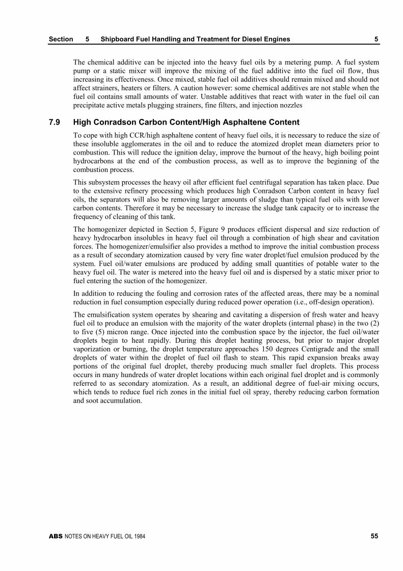
Section 5 Shipboard Fuel Handling and Treatment for Diesel Engines 5
ABS NOTES ON HEAVY FUEL OIL 1984 55
The chemical additive can be injected into the heavy fuel oils by a metering pump. A fuel systempump or a static mixer will improve the mixing of the fuel additive into the fuel oil flow, thusincreasing its effectiveness. Once mixed, stable fuel oil additives should remain mixed and should notaffect strainers, heaters or filters. A caution however: some chemical additives are not stable when thefuel oil contains small amounts of water. Unstable additives that react with water in the fuel oil canprecipitate active metals plugging strainers, fine filters, and injection nozzles
7.9 High Conradson Carbon Content/High Asphaltene Content
To cope with high CCR/high asphaltene content of heavy fuel oils, it is necessary to reduce the size ofthese insoluble agglomerates in the oil and to reduce the atomized droplet mean diameters prior tocombustion. This will reduce the ignition delay, improve the burnout of the heavy, high boiling pointhydrocarbons at the end of the combustion process, as well as to improve the beginning of thecombustion process.
This subsystem processes the heavy oil after efficient fuel centrifugal separation has taken place. Dueto the extensive refinery processing which produces high Conradson Carbon content in heavy fueloils, the separators will also be removing larger amounts of sludge than typical fuel oils with lowercarbon contents. Therefore it may be necessary to increase the sludge tank capacity or to increase thefrequency of cleaning of this tank.
The homogenizer depicted in Section 5, Figure 9 produces efficient dispersal and size reduction ofheavy hydrocarbon insolubles in heavy fuel oil through a combination of high shear and cavitationforces. The homogenizer/emulsifier also provides a method to improve the initial combustion processas a result of secondary atomization caused by very fine water droplet/fuel emulsion produced by thesystem. Fuel oil/water emulsions are produced by adding small quantities of potable water to theheavy fuel oil. The water is metered into the heavy fuel oil and is dispersed by a static mixer prior tofuel entering the suction of the homogenizer.
In addition to reducing the fouling and corrosion rates of the affected areas, there may be a nominalreduction in fuel consumption especially during reduced power operation (i.e., off-design operation).
The emulsification system operates by shearing and cavitating a dispersion of fresh water and heavyfuel oil to produce an emulsion with the majority of the water droplets (internal phase) in the two (2)to five (5) micron range. Once injected into the combustion space by the injector, the fuel oil/waterdroplets begin to heat rapidly. During this droplet heating process, but prior to major dropletvaporization or burning, the droplet temperature approaches 150 degrees Centigrade and the smalldroplets of water within the droplet of fuel oil flash to steam. This rapid expansion breaks awayportions of the original fuel droplet, thereby producing much smaller fuel droplets. This processoccurs in many hundreds of water droplet locations within each original fuel droplet and is commonlyreferred to as secondary atomization. As a result, an additional degree of fuel-air mixing occurs,which tends to reduce fuel rich zones in the initial fuel oil spray, thereby reducing carbon formationand soot accumulation.
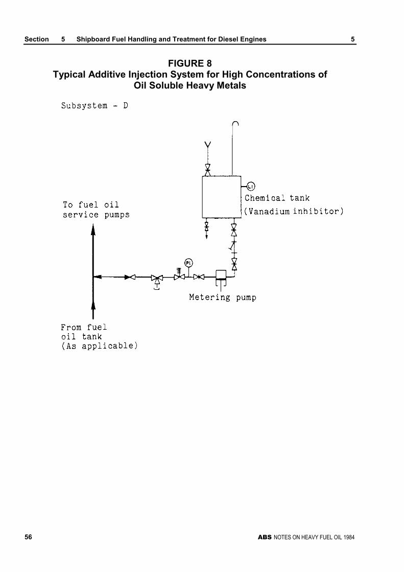
Section 5 Shipboard Fuel Handling and Treatment for Diesel Engines 5
56 ABS NOTES ON HEAVY FUEL OIL 1984
FIGURE 8Typical Additive Injection System for High Concentrations of
Oil Soluble Heavy Metals
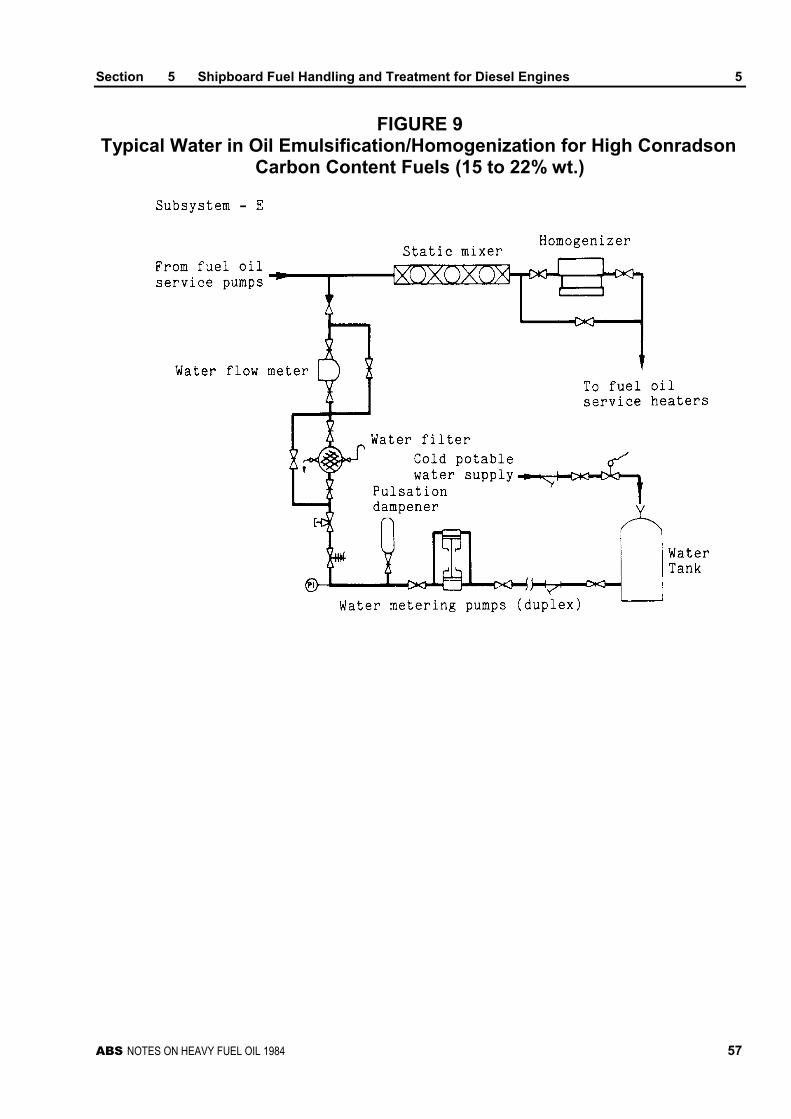
Section 5 Shipboard Fuel Handling and Treatment for Diesel Engines 5
ABS NOTES ON HEAVY FUEL OIL 1984 57
FIGURE 9Typical Water in Oil Emulsification/Homogenization for High Conradson
Carbon Content Fuels (15 to 22% wt.)

Section 5 Shipboard Fuel Handling and Treatment for Diesel Engines 5
58 ABS NOTES ON HEAVY FUEL OIL 1984
TABLE 1Fuel Property/contaminant Problem Resolution Matrix

ABS NOTES ON HEAVY FUEL OIL 1984 59
A P P E N D I X 1 Glossary and Abbreviations
CONTENTSGlossary.......................................................................................... 61
List of Abbreviations...................................................................... 65

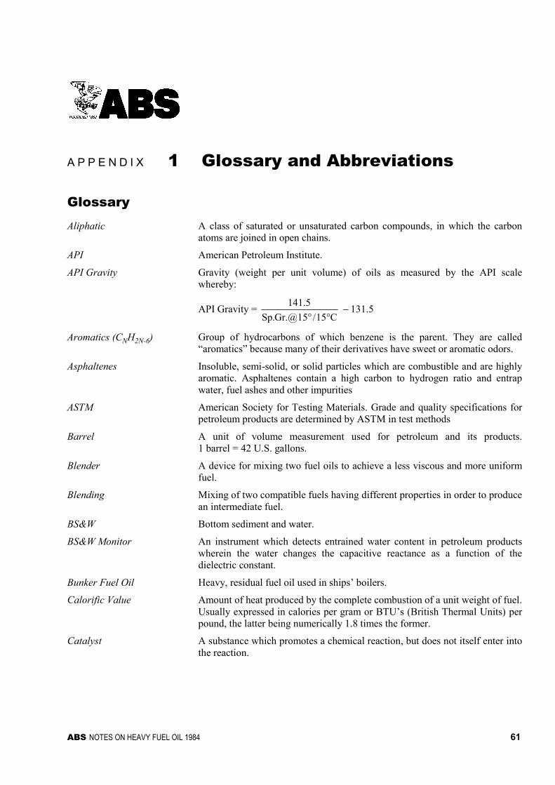
ABS NOTES ON HEAVY FUEL OIL 1984 61
A P P E N D I X 1 Glossary and Abbreviations
Glossary
Aliphatic A class of saturated or unsaturated carbon compounds, in which the carbonatoms are joined in open chains.
API American Petroleum Institute.
API Gravity Gravity (weight per unit volume) of oils as measured by the API scalewhereby:
API Gravity = C15/[email protected]
5.141
°° − 131.5
Aromatics (CNH2N-6) Group of hydrocarbons of which benzene is the parent. They are called“aromatics” because many of their derivatives have sweet or aromatic odors.
Asphaltenes Insoluble, semi-solid, or solid particles which are combustible and are highlyaromatic. Asphaltenes contain a high carbon to hydrogen ratio and entrapwater, fuel ashes and other impurities
ASTM American Society for Testing Materials. Grade and quality specifications forpetroleum products are determined by ASTM in test methods
Barrel A unit of volume measurement used for petroleum and its products.1 barrel = 42 U.S. gallons.
Blender A device for mixing two fuel oils to achieve a less viscous and more uniformfuel.
Blending Mixing of two compatible fuels having different properties in order to producean intermediate fuel.
BS&W Bottom sediment and water.
BS&W Monitor An instrument which detects entrained water content in petroleum productswherein the water changes the capacitive reactance as a function of thedielectric constant.
Bunker Fuel Oil Heavy, residual fuel oil used in ships’ boilers.
Calorific Value Amount of heat produced by the complete combustion of a unit weight of fuel.Usually expressed in calories per gram or BTU’s (British Thermal Units) perpound, the latter being numerically 1.8 times the former.
Catalyst A substance which promotes a chemical reaction, but does not itself enter intothe reaction.
Appendix 1 Glossary and Abbreviations A1
62 ABS NOTES ON HEAVY FUEL OIL 1984
Catalytic Fines Hard, abrasive crystalline particles of alumina, silica, and/or alumina silicathat can be carried over from the fluidic catalytic cracking process of residualfuel stocks. Particle size can range from sub-micron to greater than sixty (60)microns in size. These particles become more common in the higher viscositymarine bunker fuels.
Cat Cracker A large refinery vessel for processing reduced crudes or other feed-stocks inthe presence of a catalyst, as opposed to the older method of thermal cracking,which employs heat and pressure only. Catalytic cracking is generallypreferred since it produces less gas and other highly volatile byproducts. Itproduces a motor fuel of higher octane than the thermal process.
Cetane Index An empirical measure of ignition quality. Defined as the percentage byvolume of cetane in a mixture of cetane and methyl naphthalene which has thesame ignition quality when used in an engine as a fuel under test.
Clarifier A machine used for a liquid-sludge separation in which the particles with ahigher specific gravity are separated from the lower specific gravity of theliquid. A clarifier bowl has one outlet for the light phase oil; the heavier phaseparticles are retained on the bowl wall.
Cloud Point Temperature at which wax begins to crystallize from a distillate fuel.
Cracked Refers to a petroleum product produced by a secondary refining process, suchas thermal cracking or vis-breaking processes, which yield very low qualityresidua.
Cutter stock (Flux Stock) A petroleum stock which is used to reduce the viscosity of a heavier residualstock by dilution
Flash Point The lowest temperature at which a liquid will generate sufficient vapor toflash when exposed to a source of ignition.
Force Majeure A standard clause which indemnifies either or both parties to a transactionwhenever events reasonably beyond the control of either or both parties occurto prevent fulfillment of the terms of the contract.
Fraction A separate identifiable part of crude oil; the product of a refining ordistillation process.
Fuel Oil The heavy distillates from the oil refining process; used as fuel for powerstations, marine boilers.
Fungible Interchangeable. Products which can be commingled for purposes of pipelineshipment.
Gasoil Designation for No. 2 heating oils and diesel fuels. A clean distillate fuel oil.
Heavy crude Crude oil with a high specific gravity and a low API gravity due to thepresence of a high proportion of heavy hydrocarbon fractions and metalliccontent.
Homogenizer A mechanical device which is used to create a stable, uniform dispersion of aninsoluble phase (asphaltenes) within a liquid phase (fuel oil).
Layering This occurs in tanks when a high density fuel is mixed with a low density fuel.
Lifting Refers to tankers and barges taking on cargoes of oil or refined product at aterminal or transshipment point.
Light crude Crude oil with a low specific gravity and high API gravity due to the presenceof a high proportion of light hydrocarbon fractions and low metallic content.

Appendix 1 Glossary and Abbreviations A1
ABS NOTES ON HEAVY FUEL OIL 1984 63
Light Ends The more volatile products of petroleum refining; e.g., butane, propane,gasoline.
Long Ton An avoirdupois weight measure equaling 2,240 pounds.
Marine Diesel Oil (MDO) Marine Diesel Oil (MDO) is a middle distillate fuel oil which can containtraces to ten percent (10%) or more residual fuel oil from transportationcontamination and/or heavy fuel oil blending. The MDO does not requireheated storage.
Metric Ton A weight measure equal to 1,000 kilograms, 2,204.62 pounds, and 0.9842long tons.
Middle Distillate Term applied to hydrocarbons in the so-called “middle range” of refinerydistillation. Examples are heating oil, diesel fuels, and kerosene.
Motor Gasoline A complex mixture of relatively volatile hydrocarbons with or without smallquantities of additives, that have been blended to form a fuel suitable for usein spark-ignition engines.
Naphtha A volatile, colorless product of petroleum distillation. Used primarily as paintsolvent, cleaning fluid, and blendstock in gasoline production, to producemotor gasoline by blending with straight-run gasoline.
Naphthenes (CNH2M) One of three basic hydrocarbon classifications found naturally in crude oil.Naphthenes are widely used as petrochemical feedstock. Examples are;cyclopentane; methyl-, ethyl-, and propylcyclopentane
Oil Crude petroleum and other hydrocarbons produced at the wellhead in liquidform.
Olefins Class of unsaturated paraffin hydrocarbons recovered from petrol. Typicalexamples include butene, ethylene and propylene.
Petrochemical An intermediate chemical derived from petroleum, hydrocarbon liquids ornatural gas, e.g., ethylene, propylene, benzene, toluene and xylene.
Petroleum A generic name for hydrocarbons, including crude oil, natural gas liquids,natural gas and their products.
Polymerization Process of combining two or more simple molecules of the same type, calledmonomers, to form a single molecule having the same elements in the sameproportion as in the original molecules but having a different molecularweight. The product of the combination is a polymer.
Pour Point Lowest temperature at which an oil will pour or flow under certain prescribedconditions.
Purifier A machine used for a liquid-liquid separation in which the two intermixedliquids which are insoluble in each other have different specific gravities.Solids with specific gravities higher than those of the liquids can be separatedoff at the same time- A purifier bowl has two outlets; one for the light phaseliquid and one for the heavy phase liquid.
Reduced Crude Oil Crude oil that has undergone at least one distillation process to separate someof the lighter hydrocarbons. Reducing crude lowers its API gravity butincreases the handling safety by raising the flash point.
Refinery A plant used to separate the various components present in crude oil andconvert them into usable products or feedstock for other processes.
Appendix 1 Glossary and Abbreviations A1
64 ABS NOTES ON HEAVY FUEL OIL 1984
Residual Fuel Oil Heavy fuel oils produced from the non-volatile residue from the fractionaldistillation process. Heavy oils that are “leftovers” from various refiningprocesses. Heavy black oils used in ships’ boilers and in heating plants.
Short Ton An avoirdupois measure of weight equal to 2,000 lbs.
Slagging Formation of hard deposits on boiler tubes and/or piston crowns, usually dueto the presence of sodium, vanadium and sulfur.
Sludge Deposits in fuel tanks and caused by the presence of wax, sand, scale,asphaltenes, tars, water, etc.
Solvent A substance, normally a liquid, which is capable of absorbing another liquid,gas or solid to form a homogeneous mixture.
Specifications Term referring to the properties of a given crude oil or petroleum product,which are “specified” since they often vary widely even within the same gradeof product. In the normal process of negotiation, seller will guarantee buyerthat product or crude to be sold will meet certain specified limits, and willagree to have such limits certified in writing.
Generally, the major properties of oil for which a buyer would demand aguarantee are: API gravity (or specific gravity, in some cases); Sulfur, pct. wt.;Pour Point, deg C. max.; Viscosity, min./max; BS&W, pct. wt., etc.
Specific Gravity the ratio of the density of a substance at a particular temperature to the densityof water at 15 degrees Centigrade
Static Mixer A motionless mixer which has a series of fixed, geometric elements enclosedwithin a tubular housing. The internal elements impart flow division andradial mixing to the media flowing through the housing to produce a uniformdilution of the production.
Straight-Run Refers to a petroleum product produced by the primary distillation of crude oiland free of cracked components.
Stratification Occurs in blended fuels that have a compatibility problem. It is usuallyexperienced when paraffinic-based oils are mixed with asphaltic-based oils,causing asphaltenes to precipitate and settle to the bottom of a tank.
Sulfur An element that is present in crude oil and natural gas as an impurity in theform of its various compounds.
Topped Crude Oil Oil from which the light ends have been removed by a simple refiningprocess. Also referred to as “reduced crude oil.”
Total Existent Sediment Combination of inorganic and hydrocarbon sediments existing in a fuel asdelivered.
Vanadium Inhibitor An organic and/or inorganic metal bearing chemical intended to chemicallyand/or physically combine with the compounds formed during combustion ofheavy fuel oil to improve the surface properties of the treated ash compounds.
Viscometer A device for determining the viscosity of oil. There are several methods ordevices in general use. Basically, a fixed quantity of oil is allowed to passthrough a fixed orifice at a specified temperature over a measured time spanand then compared to a standard liquid such as a calibration oil or water.
Appendix 1 Glossary and Abbreviations A1
ABS NOTES ON HEAVY FUEL OIL 1984 65
Viscosity Measure of the internal friction or resistance of an oil to flow. As thetemperature of an oil is increased, its viscosity decreases and it is thereforeable to flow more readily. Viscosity is measured on several different scales,including Redwood No. 1 at 100 degrees Fahrenheit, Engler Degrees, SayboltSeconds, etc. The most common method for the designation of viscosity iskinematic viscosity, in Centistokes, cSt, at SO degrees Centigrade.
Vis-Breaking A light thermal cracking process carried out on the fuel oil during the refiningto reduce product viscosity without blending.
List of AbbreviationsAPI American Petroleum Institute
BHP Brake Horsepower
BS&W Bottom Sediment and Water
BTU British Thermal Unit
C/H Ratio Carbon/Hydrogen Ratio
CCR Conradson Carbon Residue
cSt Centistokes @ 50 degrees Centigrade
HHV Higher Heating Value
HP Horsepower
LHV Lower Heating Value
MCR Maximum Continuous Rating
MDO Marine Diesel Oil
mm Millimeter
ppm Parts per million (by weight)
rpm Revolutions per minute
Sp. Gr Specific Gravity
SR1 Seconds Redwood #1 @ 100 degrees Fahrenheit
TBN Total Base Number
TDC Top Dead Center
YR Year