Notes InfluenceLines
51
Structural Mechanics 4 CIE3109 MODULE : INFLUENCE LINES HANS WELLEMAN Civil Engineering TU-Delft date, 18 March 2014
-
Upload
dhimas-surya-negara -
Category
Documents
-
view
13 -
download
3
description
references
Transcript of Notes InfluenceLines

Structural Mechanics 4 CIE3109
MODULE : INFLUENCE LINES HANS WELLEMAN Civil Engineering TU-Delft
date, 18 March 2014

Structural Mechanics 4 Influence Lines
Ir J.W. Welleman March 2014 ii
TABLE OF CONTENT
1. INFLUENCE LINES ................................................................................................................................... 1
1.1 PROBLEM SKETCH AND ASSUMPTIONS ....................................................................................................... 1
1.1.1 Introduction of influence lines for force quantities. ........................................................................ 2
1.1.2 Work and reciprocity, Clapeyron and the theorem of Betti and Maxwell. ...................................... 6
1.1.2.1 Reciprocity, theorem of Betti and Maxwell’s law ...................................................................................... 7
1.1.2.2 example 2 : Illustration of Maxwell’s reciprocal theorem ........................................................................ 10
1.1.3 Influence lines for displacement quantities. .................................................................................. 11
1.2 STATICALLY DETERMINATE SYSTEMS ...................................................................................................... 14
1.2.1 Qualitative approach..................................................................................................................... 14
1.2.2 example 3 : influence lines for simply supported beam with a cantilever ..................................... 17
1.2.3 example 4 : Beam with a hinge ..................................................................................................... 20
1.3 STATICALLY INDETERMINATE SYSTEMS .................................................................................................. 21
1.3.1 Qualitative approach..................................................................................................................... 23
1.3.2 Quantitative calculation of influence lines .................................................................................... 25
1.3.3 Example 6 : Nth
order statically indeterminate structures ............................................................ 32
1.4 STIFFNESS DIFFERENCES IN STRUCTURES ................................................................................................. 35
1.5 SPRING SUPPORTS* .................................................................................................................................. 36
1.6 DISTRIBUTED LOADS AND INFLUENCE LINES ........................................................................................... 37
1.7 THE MOST UNFAVOURABLE POSITION OF THE LOAD ................................................................................ 38
1.8 EXERCISES ............................................................................................................................................... 41
Exercise 1 ................................................................................................................................................................. 41
Exercise 2 ................................................................................................................................................................. 41
Exercise 4 ................................................................................................................................................................. 42
1.9 APPENDIX ............................................................................................................................................ 47

Structural Mechanics 4 Influence Lines
Ir J.W. Welleman March 2014 iii
STUDY GUIDELINES
These lecture notes are part of the study material of Structural Mechanics 4. The theory and
examples in these lecture notes are presented in such a way that this topic can be mastered
through self-study. Apart from these notes with theory and examples there is additional
practice material available with extra examples, old exam questions and additional material.
An introduction to the topic of influence lines can be found in the book “Engineering
mechanics”, Volume 1, “Equilibrium” by Coen Hartsuijker and Hans Welleman, referred to
from this point on as EM-1-E. In EM-1-E chapter 16 an explanation on influence lines for
force quantities can be found for statically determinate systems. After a short introduction, the
method described in EM-1-E will be expanded and applied on influence lines for force- and
displacement quantities on statically determinate and statically indeterminate systems.
The powerpoint sheets used in the lectures will be available online on the following website:
http://icozct.tudelft.nl/TUD_CT/index.shtml
Despite the necessary precaution in putting together these lecture notes mistakes and flaws
will be inevitable. It is highly appreciated if mistakes are reported.
The teacher,
Hans Welleman
pdf-version, June 2013

Structural Mechanics 4 Influence Lines
Ir J.W. Welleman March 2014 1
1. INFLUENCE LINES
In this module the concept of influence lines will be introduced. First the concept of influence lines will be explained followed by the description of tools to construct influence lines of statically determinate and indeterminate systems for both force and displacement quantities. The theory will be applied to numerous examples.
1.1 Problem sketch and assumptions
Until now we have looked at the force distribution in a structure as a result of a static load at a
fixed location. This force distribution can be visualised using normal-, shear- and moment-
diagrams. If the position of the load is variable there is a problem in visualising the force
distribution.
Figure 1 : unit load that moves over the structure.
To find the magnitude of a force or displacement at a fixed position depending on the location
of the external load the concept of influence line is introduced.
Definition:
An influence line gives the value of a quantity in a specific point as a function of the
location of a moving unit load.
The unit load is a concentrated load with magnitude 1,0. Influence lines will be used to find
the most unfavourable position of the load for a certain quantity in statically determinate and
statically indeterminate systems. Quantities of interest could be:
- a support reaction
- a rotation in a certain point
- an internal moment in a certain cross-section
- a deflection in a specific point
- a shear force in a specific cross-section
In this chapter we will discuss how to determine influence lines for statically determinate and
indeterminate systems. In the last part the most unfavourable position of the load for a certain
quantity will be determined. For some applications only the shape of the influence line is
important. This is referred to as the qualitative aspect of the influence line. In other cases also
the exact magnitude of the influence factor is relevant. This latter aspect is referred to as the
quantitative aspect of the influence line.
1,0 kN
l
B A
AV BV

Structural Mechanics 4 Influence Lines
Ir J.W. Welleman March 2014 2
1.1.1 Introduction of influence lines for force quantities.
The concept of influence lines is introduced with the following example.
The beam in figure 2 is loaded with a concentrated load of 1,0 kN that moves from the left
support to the right support. This moving load is denoted with the horizontal dotted arrow.
Figure 2 : Example 1, moving unit load on a simply supported beam
The dynamic effects caused by the moving load are neglected completely. The problem is
considered tob e a static problem. Using this example we will introduce the influence lines for
force quantities:
• Influence lines for support reactions Av and Bv (positive reactions assumed upwards)
• Influence lines for internal forces VC and MC
Influence line for support reactions at A and B
The question is how the support reactions in A and B are related to the position of the moving
load. Equilibrium yields to:
V V
( ) 1,0 1,0l x xA B
l l
− × ×= =
The distribution of the support reaction at A and B depending on the position of the load x is
given below.
Figure 3 : Influence lines for Av and Bv.
1,0 kN
l=10 m
z
x
1,0
1,0
Influence line
AV
Influence line
BV
0,75
2,5 m
A B C
1,0 kN
l=10 m
B A C 2,5 m
AV BV

Structural Mechanics 4 Influence Lines
Ir J.W. Welleman March 2014 3
These graphs are the influence lines for Av and Bv. To determine the support reaction Av for a
load F placed somewhere on the structure we have to multiply the influence factor found from
the influence line at that location with the magnitude of the concentrated load. A load of 50
kN at 2.5 meters from the left support results in a support reaction at A of:
kN5,375075,0V =×=A
This support reaction acts upwards. It is important to take care of the signs and to pay
attention to the definition of the chosen coordinate system. Here we have chosen to plot the
positive values (upwards acting) of the support reaction downwards in the graph. Different
sign conventions are possible but must always be apparent from the assumed positive
direction of the quantity and positive coordinate directions should be depicted with an arrow.
The reader should pay attention to this. In these lecture notes we will apply the sign
convention that influence factors that correspond to upwards acting support reactions are
plotted below the x-axis.
Using the influence lines for the support reactions it is now possible to draw the influence
lines for a shear force and bending moment in a certain cross-section. It is important to realise
that a diagram will thus be drawn from which you can see the magnitude of a shear force or
moment in that specific cross-section if a unit load moves over the structure. This will be
demonstrated with two simple examples for the shear force and bending moment in a cross
section at point C (2,5 meters from the left support).
Influence line for the shear force in point C
The influence line for the shear force can be determined by calculating the influence factor for
a number of characteristic points. It seems obvious that following positions of the unit load
should be calculated:
x=0, x=2,5 (-), x=2,5 (+) en x=10,0
With (-) and (+) a cross-section just left and right of the given location is meant. Based on
equilibrium the shear force can be determined. If for example the moving unit load is located
at 2,5 meters from the left support the situation as seen in figure 4 is reached. At C the
magnitude of the shear force is 0,25 kN.
Figure 4 : Vertical equilibrium for a concentrated load at x = 2,5 (-) meters
1,0 kN
l=10 m
2,5(-) m
0,75 kN
0,25 kN
1,0 kN
0,75 kN 0,25 kN
B A C

Structural Mechanics 4 Influence Lines
Ir J.W. Welleman March 2014 4
For the characteristic points we can thus find the following values for the influence factor:
0)0,5(75,0)5,2(25,0)5,2(0)0( ==−== +− VVVV
Using these results we can create the influence line for the shear force at C. This is shown in
figure 5.
Figure 5 : Influence line for the shear force at C
In this figure we have shown to possible ways to draw the influence line. The first is based on
the deformation symbols. The second graph is based on the sign convention used in these
notes to plot positive values of the influence line always below the x-axis. Characteristic for
the influence line is that both segments are parallel and the jump in the influence line at point
C has a magnitude of 1,0.
1,0 kN
l = 10 m
z
x
Influence line
VC
0,75
2,5 m
-0,25
B A C
Influence line
VC
0,75
0,25
1,0

Structural Mechanics 4 Influence Lines
Ir J.W. Welleman March 2014 5
Influence line for the moment in point C
The influence line for the moment can also be determined using the influence line for the
support reactions. An equilibrium method will result in an influence line as shown in figure 6.
Figure 6 : Influence line for the moment in point C
The influence factor for the maximum moment at C follows from this diagram and is equal to
1,875. This is not a dimensionless number since the length is used in the calculation of this
value. Check this yourself!
Characteristic for this influence line is that the angle between both segments is equal to 1,0:
1,875 1,875
1,02,5 7,5
θ = + =
The concept of influence lines is introduced based on this example. Obviously we can also
draw influence lines for displacement quantities like deflections and rotations. For this we
need an additional tool which will be discussed in the next paragraph.
1,0 kN
l=10 m
z
x
Influence line
MC
2,5 m
1,875
B A C
1,875/2,5 1,875/7,5
θ = 1,0

Structural Mechanics 4 Influence Lines
Ir J.W. Welleman March 2014 6
1.1.2 Work and reciprocity, Clapeyron and the theorem of Betti and Maxwell.
Work is the product of a force and associated displacement. The associated displacement is
the component of the displacement in to the direction of the force as shown in figure 7. Using
vector notation work can be expressed as the dot product of the load vector F��
and
displacement vector u�
.
Figure 7 : Work generated by a force.
Obviously the work done can also be negative. In that case the force and corresponding
displacement are opposite towards each other. It is obvious that a displacement perpendicular
to the force does not contribute to the amount of work.
If on a linear elastic structure a force is applied slowly up to a value of F the structure will
deform and the deflection will grow up to a value of u. In figure 8a this situation is shown.
The force-displacement diagram is shown in figure 8b.
Figure 8 : work done by a concentrated load
If the force increases a little bit the deflection will increase with a value du. The load F will
generate additional work:
uFA dd ×=
When the final load is reached the total work is equal to:
∫ ×=u
uFA0
d
For the linear elastic structure we can easily see that the total work generated, is equal to the
area under the force-displacement curve:
FuA21=
(a) loaded situation
(b) force-displacementdiagram
u
force ukF ×=
du
F
deflection
u
F Linear elastic structure
uFA dd =
F
u
uF Work :
F orA F u A F u= × =�� �
i

Structural Mechanics 4 Influence Lines
Ir J.W. Welleman March 2014 7
In EM-1-E paragraph 15.1 the concept of strain energy is introduced. The amount of work
generated by the load is used to deform the structure. If the load is applied very slowly no
dynamics is involved and thus no kinenetic energy is involved. All generated work must be
converted into strain energy Ev.
VEA =
This direct relation between work and strain energy is also called the theorem of B.P.E.
Clapeyron (1799-1864). Clapeyron stated that for elastic systems the order in which the
system is loaded does not affect the total amount of work generated. This is because the work
is the sum of the work performed by each individual load. This principle of superposition
results in a total amount of work which must be stored in the deformed structure as strain
energy.
An application of the law of Clapeyron on a linear elastic system is shown below. The loads
are applied slowly and simultaneously to the given final values. The resulting final deflections
are shown as well.
Figure 9 : Clapeyron
The total amount of work that has to be stored as strain energy equals to:
iiuFuFuFuFEA ∑=++==
21
3321
2221
1121
V
1.1.2.1 Reciprocity, theorem of Betti and Maxwell’s law
When a structure is loaded the external forces generate work. Consider a beam loaded by two
concentrated loads applied one after the other. First the left concentrated load is slowly
applied until its final value of Fa is reached. Then the right load is applied slowly from 0 to its
final value Fb. This is shown in the left picture of figure 10.
Figuur 10 : Reciprocity
u1 u2 u3
F1 F2 F3
uaa uba
Fa Fb
ubb
uab
uaa uba
Fa Fb
ubb uab
A B A B

Structural Mechanics 4 Influence Lines
Ir J.W. Welleman March 2014 8
The displacements are shown with the first index representing the location of the
displacement and the second index indicates the point of application of the load. A
displacement uab is therefore a displacement at point A due to application of a load at point B.
The work generated by these loads for the left system equals to:
ababbb21
aaa21 uFuFuFA ×+×+×=
Please note that the load at A is applied completely before the load at B is applied. The force Fa remains constant while the force
Fb is applied.
Now we reverse the order of application of the loads. First we apply the force at B followed
by the application of the load at A. This is shown in the right picture of figure 10. The work
these point loads generate is equal to:
babaaa21
bbb21 uFuFuFA ×+×+×=
In the final situation we cannot discern in what order the loads were applied. The work
generated for both systems must be equal. This results in:
bababa uFuF =
This expression is known as the theorem of Betti. Maxwell has introduced the concept of
influence factor based on this theorem which we can use to define the deflection due to a load.
bbbbbababa
bababaaaaa
FcuFcu
FcuFcu
==
==
If we substitute these influence factors in the equation we found we obtain:
baab
ababbaba
cc
FcFFcF
=
=
This result reveals that the displacement at A due to a unit load at B is equal to the
displacement at B due to a unit load at point A. This is known as Maxwell’s reciprocal law.
The total deflection at A and B can now also be written as:
bbbababbbab
babaaaabaaa
FcFcuuu
FcFcuuu
+=+=
+=+=
Applying Maxwell and using a matrix-notation finally results in:
=
b
a
bbab
abaa
b
a
F
F
cc
cc
u
u
This relation is known as the flexibility relation and by using Maxwell’s reciprocal law this
matrix must be a symmetrical matrix.

Structural Mechanics 4 Influence Lines
Ir J.W. Welleman March 2014 9
Maxwell’s reciprocal law is derived here using forces and the displacements at different
positions. However this law is not restricted to this case only. The force vector can also be
comprised of couples and the degrees of freedom can also contain rotations thus resulting in
the following symmetrical matrix:
=
b
b
a
a
44342414
34332313
24232212
14131211
b
b
a
a
T
F
T
F
cccc
cccc
cccc
cccc
u
u
ϕ
ϕ
Two reciprocal relations are of particular interest here:
• The displacement at A due to a unit couple at A is equal to the rotation at A due a unit
load at A.
• The displacement at A due to a unit couple at B is equal to the rotation at B due to a
unit load at A.
These properties will be used later on influence lines.
The inverse of the flexibility relation is called the stiffness relation which can be written as:
−
−=
=
−
b
a
aaab
abbb
b
a
1
bbab
abaa
b
a
det
1
u
u
cc
cc
u
u
cc
cc
F
F
2
abbbaadet ccc −=
This stiffness relation can also be written as:
=
b
a
bbab
abaa
b
a
u
u
kk
kk
F
F
The stifness components can be expressed in terms of Maxwell’s influence factors:
2
abbbaa
aa
bb
2
abbbaa
abab
2
abbbaa
bb
aa
ccc
ck
ccc
ck
ccc
ck
−=
−−=
−=
The stiffness matrix is thus also a symmetrical matrix. Without elaborating on the proof behind this we
note that the determinant of the flexibility matrix is positive which means that the diagonal terms in the
stiffness matrix must always be positive. It can be proven that the eigenvalues of this matrix are all
positive and not equal to zero. This will result in a so-called positive-definite stiffness matrix.

Structural Mechanics 4 Influence Lines
Ir J.W. Welleman March 2014 10
1.1.2.2 example 2 : Illustration of Maxwell’s reciprocal theorem
In figure 11 a cantilever beam is shown that is loaded by a concentrated load and a couple at
point B.
Figure 11 : Cantilever beam loaded with a concentrated load and couple at the free end.
Using the “forget-me-nots” we can determine the deflections at the free end. For the vertical
displacement and rotation at point B the following equations must hold:
EI
lT
EI
lF
EI
lT
EI
lFw
B
2
B
B
2
B
3
BB
2
23
+=
+=
ϕ
In Matrix-notation this can be written as:
=
B
B
2
23
B
B
2
23T
F
EI
l
EI
lEI
l
EI
lw
ϕ
At the end of the beam the rotation due to a unit load F is equal to the deflection caused by a
unit couple T. This is in full compliance with Maxwell’s reciprocal theorem.
l
FB
wB
EI
TB ϕB x
A B

Structural Mechanics 4 Influence Lines
Ir J.W. Welleman March 2014 11
1.1.3 Influence lines for displacement quantities.
Using the tools we developed in the last paragraph we can now determine the influence lines
for displacement quantities. This will be applied on the example of a simply supported beam.
First we will look at the influence line for the vertical displacement and then we will look at
the influence line for the rotation of a specific point on the beam axis.
Influence line for the vertical displacement at point C.
To determine the influence line of the deflection at C we will first investigate the deflection at
C due to different point of application of the load. In figure 12 the structure is drawn again
with a number of characteristic points.
Figure 12 : Determining the deflection at C for several positions of the unit load.
To be able to draw the influence line we need the influence factors for several characteristic
points of the moving load. In figure 12 three positions of the unit load are investigated. The
influence factors for the deflection at C due to the three load positions are:
cc cd ce, andw w w
It is not necessary to determine the influence factors by moving the unit load to a different
position since Maxwell’s reciprocal theorem holds:
ecce
dccd
ww
ww
=
=
This means that the deflected beam due to a unit load at C is equal to the influence line for the
deflection at C. Check this yourself thoroughly!
To determine the value of the influence factors the deflection has to be determined for a unit
load at point C. This can be done in several ways:
- By using the forget-me-nots
- Method of elastic weights
- By application of the moment-area theorem (M/EI-diagram)
- By using computer software like for example: MatrixFrame
1,0 kN
4 × 2,5 m
B A C D E
1,0 kN 1,0 kN
wcc wdc wec

Structural Mechanics 4 Influence Lines
Ir J.W. Welleman March 2014 12
Try to determine the deflection line as shown in figure 13 yourself using one of the above
mentioned methods.
Figure 13 : Influence line for the deflection at point C
Influence line for the rotation in point C
In the diagram below the requested influence factors for the rotation at C are indicated.
Figure 14 : Rotation of the cross-section at C due to a moving unit load
For different positions of the unit load we monitor the slope of the deflection line at point C.
To determine the influence factors of the influence line for a rotation at point C we can once
again make use of Maxwell’s reciprocal theorem.
1,0 kN
4 × 2,5 m
B A C D E
11,718/EI Influence line for the
deflection in point C 14,322/EI
9,114/EI
1,0 kN
4 × 2,5 m
B A C D E
Deflection due to F at C
1,0 kN 1,0 kN
Deflection due to F at D
Deflection due to F at E
ϕcc
ϕcd
ϕce

Structural Mechanics 4 Influence Lines
Ir J.W. Welleman March 2014 13
According to Maxwell the following holds:
=
d
d
c
c
44342414
34332313
24232212
14131211
d
d
c
c
T
F
T
F
cccc
cccc
cccc
cccc
w
w
ϕ
ϕ
• The displacement in C due to a unit load at D is equal to the displacement at D caused by
a unit load at C.
• The displacement at C due to a unit couple at C is equal to the rotation in C as a result of
the unit load at C.
• The displacement at C due to a unit couple at D is equal to the rotation at D caused by a
unit load at C.
Based on the reciprocal relations above and the influence factors can be obtained with:
Step 1: The rotation at C due to a unit load at C (=desired influence factor) is equal to the deflection at
C as a result of a unit couple at C.
12c12c
12c12c
)0,1(
)0,1(
cTcw
cFc
==×=
==×=ϕ
Step 2 The rotation at C due to a unit load at D (=desired influence factor) is equal to the deflection at
D due to a unit couple at C.
23c23d
23d23c
)0,1(
)0,1(
cTcw
cFc
==×=
==×=ϕ
The result of these steps is that the deflection line due to a unit couple in C is the requested
influence line for the rotation of the cross-section at C. In the figure below this approach is
applied to the simply supported beam.
Figure 15 : Influence line for the rotation at C
Determining the value of the influence factors is left to the reader. In an identical manner as
described for the influence line for the deflection these influence factors can be obtained for
characteristic points of the beam. From this introduction it is apparent that determining the
influence factors of displacement quantities is somewhat laborious and a general procedure
for force quantities is yet missing. In the next paragraph we develop a convenient and fast
method to draw influence lines for force quantities.
l=10 m
B A C D E
Influence line for the
rotation at C
TC=1,0 kNm
Structural Mechanics 4 Influence Lines
Ir J.W. Welleman March 2014 14
1.2 Statically determinate systems
In the previous paragraph the concept of influence lines has been introduced. For statically
determinate systems we will now present a fast method to determine influence lines for force
quantities based on a qualitative approach. To determine influence lines that correspond to
displacements the method shown in the previous paragraph can be used.
1.2.1 Qualitative approach
To determine the influence line in the previous paragraph we put the load at a specific point
and found the force distribution based up on equilibrium. Repeating this procedure for several
characteristic points of the load leads to the required influence line. Professor Heinrich
Müller-Breslau introduced a qualitative and fast way to determine influence lines of force
quantities that is based on virtual work.
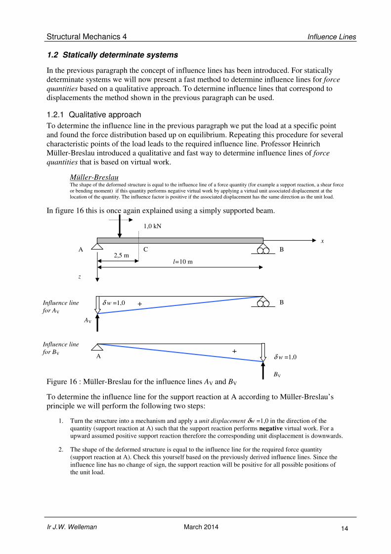
Müller-Breslau The shape of the deformed structure is equal to the influence line of a force quantity (for example a support reaction, a shear force
or bending moment) if this quantity performs negative virtual work by applying a virtual unit associated displacement at the
location of the quantity. The influence factor is positive if the associated displacement has the same direction as the unit load.
In figure 16 this is once again explained using a simply supported beam.
Figure 16 : Müller-Breslau for the influence lines AV and BV
To determine the influence line for the support reaction at A according to Müller-Breslau’s
principle we will perform the following two steps:
1. Turn the structure into a mechanism and apply a unit displacement δw =1,0 in the direction of the
quantity (support reaction at A) such that the support reaction performs negative virtual work. For a
upward assumed positive support reaction therefore the corresponding unit displacement is downwards.
2. The shape of the deformed structure is equal to the influence line for the required force quantity
(support reaction at A). Check this yourself based on the previously derived influence lines. Since the
influence line has no change of sign, the support reaction will be positive for all possible positions of
the unit load.
+
+
1,0 kN
l=10 m
B A C 2,5 m
B
AV
δ w =1,0 Influence line
for AV
A
BV
δ w =1,0
Influence line
for BV
x
z

Structural Mechanics 4 Influence Lines
Ir J.W. Welleman March 2014 15
The prove for this approach can be shown using the principle of virtual work. Releasing one
of the degrees of freedom changes the structure into a mechanism. The virtual work generated
by all external loads due to a kinematically admissible virtual displacement δw must be zero.
The support reaction generates negative virtual work due to the imposed virtual
displacement. The unit load in this case will generate positive work. Applying the principle of
virtual work for the load at A results in:
V
V
load at A: 1,0 0
1,0
w A w
A
δ δ− × + × = ⇔
= ↑
V
V
load at : 1,0 0x
x
x w A w
A w
δ δ
δ
− × + × = ⇔
= ↑
This result is equal to the influence factor we found for the support reaction at A due to a unit
load at A. In a similar way we can derive an influence factor for a unit load at x which will
give an expression which is identical to the displaced mechanism (right expressions).
For the internal forces like the shear force and the bending moment we can also apply Müller-
Breslau’s principle. To determine the influence line for a bending moment we have to perform
the following steps:
1. The structure has to be turned into a mechanism. By placing a hinge at C we have
created a mechanism. This is shown in figure 17. The virtual unit displacement
corresponding to the internal moment is a rotation of δθ =1,0
2. The displaced structure is the influence line. The influence factor at C for the bending
moment follows from the displacement at point C. With the geometric relation
between the unit rotation and the deflection at C the influence factor can be found.
This is demonstrated in the figure below.
Figure 17 : Müller-Breslau for the influence line MC
The displaced structure is the influence line for MC . The influence factor at C is 1,875. The
positive axis of the influence line is indicated by the black arrow with the + at the origin. The
influence line is positive over the entire length of the beam since the displacement has the
same direction as the unit load for all positions of the load.
With virtual work the result found can be checked. Use the mechanism from figure 17 with a
virtual displacement at C equal to δw. Zero total virtual work results in:
1,0 kN
l=10 m
z
x
Influence line
MC
2,5 m
B A C
S MC MC
δ w
δ θ =1,0 875,1
0,15,75,2
=
=+=
w
ww
δ
δδδθ
+

Structural Mechanics 4 Influence Lines
Ir J.W. Welleman March 2014 16
{ }kNm875,1
00,1
0
C
5,71
5,21
C
C
=
+×=
=×−×
=
M
wMw
Mw
A
δδ
δθδ
δ
This result is indeed the same as the previously found result.
remark : The bending moment generates negative work. This can be seen by splitting the
mechanism in two parts at point C and checking how the bending moments act on the
two beam ends and how these beams rotate. The figure below shows for both beam
ends opposite direction of the beam axis rotation and the bending moments at the
beam ends. The generated work is therefore negative.
Figure 18 : Work generated by bending moments at C
For the shear force we also need to find a mechanism in which the shear force generates
negative work due to a kinematically admissible unit displacement. This can be achieved by
placing a sliding hinge at the position of the cross section for which we have to determine the
influence line. This can be seen in figure 19. The shear force is drawn in its positive direction,
the sliding hinge is moved in the direction opposite to the direction of the force. The shear
force thus generates negative work.
Figure 19 : Müller-Breslau for the influence line VC
From the geometric demands1 of the mechanism we can find the values of the influence
factors. In this way we directly find the influence line as we derived earlier in figure 5. The
influence factor is positive when the displacement has the same direction as the unit load.
With these examples it has been shown that the principle of Müller-Breslau complies with the
virtual work method. Ensure that the required force quantity generates negative work in order
to obtain the correct influence line including the sign. The influence line will be equal to the
displaced mechanism.
1 Only the shear force has to generate work not the bending moment. The beam axis is therefore not allowed to
rotate at the sliding hinge.
1,0 kN
l=10 m
z
x
Influence line
VC
2,5 m
B A C
“sliding hinge”
VC
VC
δ w=1,0
+
δw
MC MC 5,72
wδθ =
5,21
wδθ = x
z
ϕ
Structural Mechanics 4 Influence Lines
Ir J.W. Welleman March 2014 17
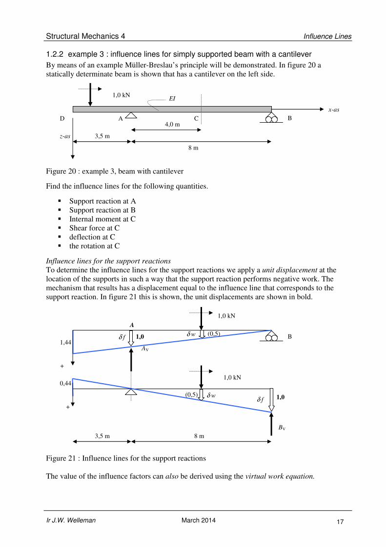
1.2.2 example 3 : influence lines for simply supported beam with a cantilever
By means of an example Müller-Breslau’s principle will be demonstrated. In figure 20 a
statically determinate beam is shown that has a cantilever on the left side.
Figure 20 : example 3, beam with cantilever
Find the influence lines for the following quantities.
� Support reaction at A
� Support reaction at B
� Internal moment at C
� Shear force at C
� deflection at C
� the rotation at C
Influence lines for the support reactions
To determine the influence lines for the support reactions we apply a unit displacement at the
location of the supports in such a way that the support reaction performs negative work. The
mechanism that results has a displacement equal to the influence line that corresponds to the
support reaction. In figure 21 this is shown, the unit displacements are shown in bold.
Figure 21 : Influence lines for the support reactions
The value of the influence factors can also be derived using the virtual work equation.
A
8 m 3,5 m
B δ f
δ f
BV
AV
1,0 kN
1,0 kN
δ w
δ w
+
+
1,0 (0,5)
1,44
1,0 (0,5)
0,44
1,0 kN
8 m
B A C 4,0 m
x-as
z-as 3,5 m
D
EI

Structural Mechanics 4 Influence Lines
Ir J.W. Welleman March 2014 18
By applying a unit load at the location of interest we can use virtual work to determine this
influence factor, e.g. for point C the following results:
1V 2
1V 2
1,0 0 with :8 4
1,0 0,5
f wA f A w w f
wA
f
δ δδ δ δ δ δ
δδ
= − × + × = = ⇒ =
= = × =
These influence factors are shown in brackets in figure 21. The support reaction at A is
always upwards, but this does not hold for the support reaction at B!
Influence lines for internal forces
To find the influence line for the bending moment in the cross-section at point C we apply:
• Create a mechanism by placing a hinge at C.
• Apply a unit rotation at C such that the bending moment MC generates negative work.
• The displaced shape of the mechanism is the required influence line.
This is shown in figure 22.
Figure 22 : Influence line for MC.
From the geometrical demands of the mechanism can be seen that the deflection at C is equal
to 2,0. This is the influence factor for the bending moment at C due to a unit load at C:
kNm0,210,2CC =×=M
This same value can be found based on equilibrium: 0,280,125,041
CC =××== FlM kNm
To find the shear force at C we also have to create a mechanism such that a unit displacement
that corresponds to the force quantity (shear force) can be applied. In figure 23 a sliding hinge
is placed at C to create the mechanism.
Figure 23 : Influence line for the shear force at point C
8 m 3,5 m
δ w
+ δδδδθθθθ = 1,0
(2,0)
1,75
8 m 3,5 m +
1,0
0,4375
0,5
0,5

Structural Mechanics 4 Influence Lines
Ir J.W. Welleman March 2014 19
Influence lines for the displacements
To determine the influence lines for displacements we will make use of the deflection line due
to a unit load as derived in paragraph 1.1.3. To determine the influence line for the vertical
deflection at C we must place the unit load at point C. The resulting deflection line is the
influence line we are looking for.
Figure 24 : Influence line for the deflection at C
The maximum deflection at the C can be found using the forget-me-nots:
EIEI
Fw
EIEI
Fw
145,3
16
85,3
667,10
48
8 2
CD
3
CC −=××
−=×−==×
= θ
To find the influence line for the rotation at C we have to apply a unit couple at C. In this case
the influence line we are looking for is also equal to the deflection line that results from this
unit couple. This deflection line is shown in figure 25.
Figure 25 : Influence line for the rotation at C
The displacement at C is zero. This means that the rotation at C due to a unit load at C is
equal to zero. For point D the influence factor can be derived using the forget-me-nots :
EIEI
Tw
1667,15,3
24
8CD −=×
×−=
8 m 3,5 m
1,0
+
1,1667/EI
D C
8 m 3,5 m
1,0
+ 10,667/EI
14,0/EI
D C A B θ
Structural Mechanics 4 Influence Lines
Ir J.W. Welleman March 2014 20
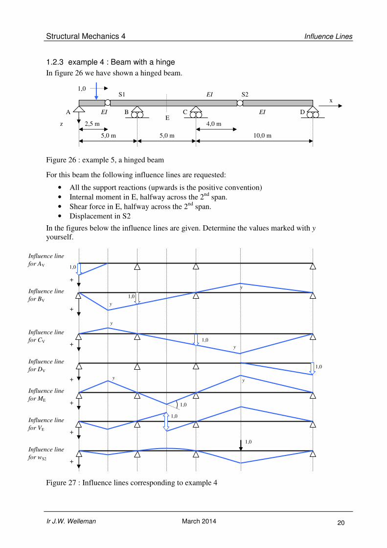
1.2.3 example 4 : Beam with a hinge
In figure 26 we have shown a hinged beam.
Figure 26 : example 5, a hinged beam
For this beam the following influence lines are requested:
• All the support reactions (upwards is the positive convention)
• Internal moment in E, halfway across the 2nd
span.
• Shear force in E, halfway across the 2nd
span.
• Displacement in S2
In the figures below the influence lines are given. Determine the values marked with y
yourself.
Figure 27 : Influence lines corresponding to example 4
Influence line
for AV
Influence line
for BV
Influence line
for CV
Influence line
for DV
Influence line
for ME
Influence line
for VE +
Influence line
for wS2
+
+
+
+
+
+
1,0
1,0
1,0
y
y
1,0
y
y
1,0
1,0
y y
1,0
5,0 m 5,0 m 10,0 m
4,0 m 2,5 m
S2 S1 EI
EI EI
z
x
1,0
A B C D E

Structural Mechanics 4 Influence Lines
Ir J.W. Welleman March 2014 21
1.3 Statically indeterminate systems
For statically indeterminate structures a similar approach as for statically determinate
structures can be applied to find the influence lines for force quantities. There is one
important difference though. The influence lines for all the force quantities are no longer
linear functions but they are curved. This will be illustrated with a statically indeterminate
beam as shown in figure 28. This structure has one redundant since it is statically
indeterminate to the degree of one.
Figuur 28 : Statically indeterminate beam
The clamping moment TB (negative bending moment) at B can be determined using the
forget-me-nots. The compatibility equation with respect to the deformation is that the rotation
in point B has to be equal to zero:
BB2
22
B
B
22B
AB
en2
)(
036
)(
TMl
xlFxT
EI
lT
EIl
xlFx
−=−
=
=−−
=ϕ
The clamping moment works in the shown direction for all values of x between 0 and l. The
vertical support reactions in A and B can be found from equilibrium. Check for yourself that
the results you find for these are equal to:
VV
3
323
V
1
2
23)(
AB
Fl
lxlx
l
T
l
xlFA B
−=
×+−
=−−
=
The support reactions act upwards for all values of x between 0 and l. With the functions we
have derived above the influence lines are now determined. For a number of values in
between the influence factors can be determined. In the table below these values are given for
points A, B, C and D.
Table : Influence factors
x/l AV ][ F× BV ][ F× TB ][ Fl× MB ][ Fl×
0,00 1,0000 0,0000 0,0000 -0,0000
0,25 0,6328 0,3672 0,1172 -0,1172
0,50 0,3125 0,6875 0,1875 -0,1875
0,75 0,0859 0,9141 0,1641 -0,1641
1,00 0,0000 1,0000 0,0000 -0,0000
1,0 kN
l
B A C
x=0,25 l
D
x=0,75 l
TB
BV AV

Structural Mechanics 4 Influence Lines
Ir J.W. Welleman March 2014 22
The influence lines for the force quantities can be plotted with this data. In figure 29 this
result is shown. These influence lines are no longer straight. Check for yourself that the
maxim value of the clamping moment is found if the unit load is placed at a distance
lx 331= .
Figure 29 : Influence lines for a statically indeterminate beam.
The consequence of this “discovery” is that determining the exact shape of the influence line
becomes a more laborious process than in statically determinate cases. Especially drawing the
influence lines for shear forces and bending moments in a cross section is a bit more work.
That is the reason we have not looked at them at first. In the next paragraph we will explain
that it is not always necessary to determine the exact shape of the influence line and that we
can suffice with the following:
• Values at the characteristic points,
• combined with the knowledge that the influence line is curved,
• and the shape can be determined with the principle of Müller-Breslau as described
before.
1,0 kN
l
B A C
Influence line
for MB
D
Influence line
for AV
Influence line
for BV
0,12l 0,19 l
0,16 l
1,00
0,31
0,63
0,09
1,0 0,37
0,69 0,91

Structural Mechanics 4 Influence Lines
Ir J.W. Welleman March 2014 23
1.3.1 Qualitative approach
When determining influence lines for statically determinate systems we have used the
following approach:
Displacement quantitites:
• Apply a unit load that corresponds to the requested displacement quantitiy, the
deformed shape is the influence line
Force quantities:
• Apply a unit displacement that corresponds to the force quantity you are interested in
such that the quantity performs negative work. The deformed shape is the desired
influence line. The quantity is positive for displacements in the direction of the unit
load.
To apply the unit displacement we added a degree of freedom by introducing a sliding hinge
or hinge (shear force, bending moment) or by removing one of the supports. For a statically
determinate structure this approach results in a mechanism. For statically indeterminate
systems the same approach will be used. The difference is that because the systems is
indeterminate the released structure will not be a mechanism. This principle will be applied on
the indeterminate structure of figure 28. The proof for this approach is found in the
APPENDIX.
Influence lines for the support reactions
To determine the influence line for the support reactions we have to apply a unit displacement
at the point of interest. In figure 30 this is illustrated for both support reactions.
Figure 30 : Influence lines for the support reactions according to Müller-Breslau
Without immediately determining the influence factors we quickly have a good view of the
influence line. Pay attention with this method that only the displacement that corresponds to
the force quantity you are looking for is given a unit displacement. This can be seen at the
right support, the clamped end results in a horizontal tangent for both influence lines at the
right end.
1,0 kN
l
B A
1,0
1,0
Influence line
for AV
Influence line
for BV
BV AV

Structural Mechanics 4 Influence Lines
Ir J.W. Welleman March 2014 24
The clamping moment at support B is of course also a support reaction. Here we can also
apply the same principle. The displacement that corresponds with the clamping moment is the
rotation of point B. Assume a positive moment in the beam and apply at B a unit rotation
such that TB performs negative work. The result is the displacement field as shown in figure
31. This is the influence line we are looking for.
Figure 31 : Influence line for the clamping moment at B.
The determination of the influence factor for characteristic points will be addressed later.
Influence lines for the internal forces
To determine the influence line for the shear force and the internal moment we can also apply
Müller-Breslau’s principle. The shape of the influence line for the shear force at point C is
sketched in figure 32. Pay attention: we have applied a sliding connection, the slope left and
right of C has to be the same! (otherwise the bending moment would also perform work.)
Figure 32 : Influence line for the shear force at point C
1,0 kN
l
B A
Influence line
for VC
C
1,0
1,0 kN
l
B A
θ = 1,0
0,1875 l
Influence line
for MB
TB
TB
MB

Structural Mechanics 4 Influence Lines
Ir J.W. Welleman March 2014 25
The influence line for the internal moment at point C can also be drawn in the same manner.
This is shown in figure 33.
Figure 33 : Influence line for the internal moment in point C
An important difference between the influence lines for statically determinate and
indeterminate systems is that the influence lines are not linear. In figure 33 for example the
part AC cannot be straight since the connecting parts at C have to make an angle equal to a
unit rotation!
1.3.2 Quantitative calculation of influence lines
Next to the previously shown qualitative approach it is necessary to determine the influence
factors at some characteristic points. This will be shown based upon the previous example.
Support reaction in A
From the influence line as shown in figure 30 we want to find the influence factor at mid
span. There are again multiple methods at our disposal to determine this influence factor. One
option is to use the force method based on the forget-me-nots to determine the force
distribution in the beam. To do so we apply a unit load at mid span. Then we create a
statically determinate system by removing the support at A. As a compatibility equation we
demand zero deflection at point A (there is a support there). This approach is further clarified
in figure 34.
Figure 34 : Support reaction at A due to a unit load at E
The demand for zero deflection at A using the forget-me-nots results in the following
expression for the vertical support reaction at A:
1,0 kN
l
B A
Influence line
for MC
C
1,0
B E
½l AV
½l
z-as
x-as
1,0

Structural Mechanics 4 Influence Lines
Ir J.W. Welleman March 2014 26
( ) ( )
3125,016
5
2
0,1
3
0,1
30
V
21
2
213
213
A
==
××
+×
+×
−==
A
lEI
l
EI
l
EI
lAw V
This influence factor for the support reaction at A due to a unit load at E was already
indicated in figure 29.
Internal Moment in B
To determine the influence line for the clamping moment at B we will apply a unit rotation at
point B. The deflection line we obtain using this method is the requested influence line. This
load case is shown in figure 35. The deflection at mid span can be determined using for
example the forget-me-nots or the moment-area theorem.
Figure 35 : Deflection line due to a unit roation at B.
The rotation at B is equal to -1,0. Using a forget-me-not we can thus determine the clamping
moment at B:
l
EIM
EI
lM 30,1
3B
BB −=⇒−==ϕ
Using the second moment-area theorem we can also determine the deflection at mid span. The
reader is asked to check these results:
lwE 163−=
This deflection is the requested influence factor for the clamping moment at point B due to a
unit load at E:
lM 1875,0B −=
This value corresponds to the value indicated in figure 29.
kwispel-effect
1,0 Deflection line
for a unit
rotation in B
l
3 5,0A =ϕ
83
23
21
21 ** ==
llθ
la61=
M/EI – diagram
(moment-area
theorem)
x
z
M/EI
0,5
E
MB

Structural Mechanics 4 Influence Lines
Ir J.W. Welleman March 2014 27
Influence line for the bending moment at C
To determine the characteristic values of the influence line for the bending moment at C we
can use the influence line for the support reaction at A. The influence factor can be
determined using the following:
1
C V 4
1C V 4
0 0,25 : 1,0 (0,25 )
0, 25 :
x l M A l l x
l x l M A l
≤ ≤ = × − × −
≤ ≤ = ×
In the table below the influence factor for several values of x have been collected.
Table : Influence factors for MC
x MC [*Fl] 0,00 0,0000
0,10 0,0626
0,20 0,1260
0,25 0,1582
0,30 0,1409
0,40 0,1080
0,50 0,0781
0,75 0,0214
1,00 0,0000
The influence line for MC is shown in figure 36. The line appears linear for the part AC but it
actually isn’t, to see this check the values in the table above and the earlier remark about this
that corresponds to figure 33.
Figure 36 : Influence line for MC.
The influence line for the shear force can be determined in the same manner. Determine for
yourself several characteristic values of the influence factor and draw the influence line based
on figure 36.
1,0 kN
l B A
Influence line
for MC
C
0,158 l

Structural Mechanics 4 Influence Lines
Ir J.W. Welleman March 2014 28
Example 5 : Continuous beam with three supports
In figure 37 a continuous beam with three supports is drawn.
Figure 37 : Example 5, continuous beam with three supports
The question is to determine the following influence lines:
o Support reactions at A, B and C
o Bending moment MD
o deflection at D
Before we will determine the influence lines precisely we will first use a qualitative approach
to sketch the correct shape of the influence lines. Based on these sketches we can then
determine for which characteristic points we have to calculate the exact values of the
influence factors to get a sufficiently accurate influence line.
Qualitative approach
Based on Müller-Breslau’s principle we can sketch the correct shape of the influence line. For
force quantities we apply a unit displacement, for displacement quantities we apply a unit
load. Check for yourself that the shown influence lines of figure 38 comply with this approach
in terms of shape.
Figure 38 : Example 5, qualitative influence lines
4,0 m 2,0 m
EI
C A B D
1,0 m 1,0
1,0
1,0
1,0
1,0
Influence line for AV
Influence line for BV
Influence line for CV
Influence line for MD
Influence line for wD
1,0

Structural Mechanics 4 Influence Lines
Ir J.W. Welleman March 2014 29
For the support reactions the influence lines we have found so far based on this approach are
quite accurate already. To be able to determine the influence line for the bending moment at
point D it is convenient if we first determine the influence line for the support reaction at C.
This is why we will discuss, for completeness, all the influence lines in a quantitative way.
Quantitative approach, support reactions
To determine the support reactions one can make use of several methods. The fastest method
would of course be to use some computer software to solve the problem. In these lecture notes
though we will once again make use of the forget-me-nots.
The structure is statically indeterminate to the first degree. If the support reaction at B is
chosen as the unknown redundant (so we remove the support at B) we need a compatibility
demand for zero deflection at B, since the beam is supported at B. The influence line for the
support reaction at B can then be determined in the same way as the previous example. This is
clarified in figure 39 in which a positive support reaction is assumed to act downwards. This
choice is made to make Maxwell’s formulas more recognizable in this example.
Figure 39 : Compatibility demand at B
The support reaction RBX at B due to a unit load at a distance x can be determined as follows:
bb
xb
bb
bxBX
BXbbbxbbbxB 00,10
c
c
c
cR
Rccwww
−=−=
=×+×=+==
The influence line can be determined by calculating the deflection at several points along the
beam due to a unit load at B. This means one single load case! These deflections are then
scaled by the deflection at B due to the unit load. This approach is basically a proof for the
method that was introduced in 1886 by Müller-Breslau. See for this proof, also the
APPENDIX.
4,0 m 2,0 m
EI
C A B
1,0
x
C A B
wbx
1,0
x
C A B
wbb
RBX
Please note we apply Maxwell’s law
here.

Structural Mechanics 4 Influence Lines
Ir J.W. Welleman March 2014 30
This calculation can be exectued in several ways. Here forget-me-nots will be used to
ccalculate the influence factor cxb once every meter along the beam.
determining cbx:
To determine the deflection at B due to a unit load at B using forget-me-not’s:
Figure 40 : forget-me-not for a point load
The deflection due to a concentrated load at B can be determined for every meter along the
beam using the moment-area theorem as has been done in a previous example. The results are
collected in the following table:
Table : Influence factors for cbx
x cbx 0 0
1
EI9
19
2
EI9
32
3
EI9
5,34
4
EI9
28
5
EI9
5,15
6 0
With this set of data we can determine the influence factors of the influence line, for several
characteristic points by making use of:
bb
xb
bb
bx
BXc
c
c
cR −=−=
Obviously because of the scaling the influence factor at B will be equal to -1,0 and at A and C
it’s must be equal to 0,0.
b = 4,0 a = 2,0
EI
A B
1,0
A
C
2 2 2 2
BB
( )
6
( )
6
32
3 3 9bb
F ab l b
lEI
F ab l a
lEI
Fa b a bw c
lEI lEI EI
ϕ
ϕ
× += −
× +=
= ⇔ = =
C x
z

Structural Mechanics 4 Influence Lines
Ir J.W. Welleman March 2014 31
With this we find the following results:
Table : influence factors for RB
x RB 0,0 0,000
1,0 -0,594
2,0 -1,000
3,0 -1,078
4,0 -0,875
5,0 -0,484
6,0 0,000
remark:
The influence factors can obviously also be found using computer software. By placing a unit load at
point B and determining the deflection for every meter we can quickly determine the influence line.
This means that we can find the influence line based on one load case with one calculation!
The influence line for RB can now be plotted accurately. Based on equilibrium all values of
the other support reactions can be found. In the table below the influence factors of all the
support reactions have been listed. In figure 41 all influence lines have been drawn again
making use of the standard conventions for directions and signs of the support reactions.
Table : Influence factors for the support reactions
x RA RB RC 0,0 -1,000 0,000 0,000
1,0 -0,437 -0,594 0,031
2,0 0,000 -1,000 0,000
3,0 0,219 -1,078 -0,141
4,0 0,250 -0,875 -0,375
5,0 0,156 -0,484 -0,672
6,0 0,000 -0,000 -1,000
Figure 41 : Influence line for the vertical support reactions at A, B and C
For these influence lines the standard conventions for vertical support reactions is used:
upwards acting reactions are positive which is plotted downwards in the influence line. These
lines show a clear resemblance with the expectations from the qualitative approach.
1,0
1,0
1,0
Influence line for AV
Influence line for BV
Influence line for CV
1,078
0,141
Note:
The assumed direction of the support reaction
B was wrong. The influence factors we found
are all negative! The correct direction is
upwards.
For the drawing of the influence lines the
standard conventions for signs and directions
is used. The vertical support reactions are
now AV, BV and CV. These support reactions
are positive if they act upwards. For all
influence lines holds that positive values are
plotted downwards.

Structural Mechanics 4 Influence Lines
Ir J.W. Welleman March 2014 32
Influence line for MD
The influence line for the bending moment at D can be determined using the found influence
line for CV. Check for yourself that following influence factors are found:
Table : Influence factors for MD
x MD ][ l×
0,0 0,000
1,0 -0,031
2,0 0,000
3,0 0,141
4,0 0,375
5,0 0,672
6,0 0,000
The influence line is shown in figure 42 (not to scale).
Figure 42 : Influence line for MD
1.3.3 Example 6 : Nth order statically indeterminate structures
The structures discussed so far have been statically indeterminate with one single redundant.
For nth
-times statically indeterminate structures the same solution strategy can be applied. For
these cases n unknowns are chosen accompanied by n compatibility equations. In figure 43 a
2-times statically indeterminate beam is shown together with the statically determinate
auxiliary system with the two unknowns, the vertical support reactions at B and C. Positive
support reaction are in this case assumed to act downwards. This choice is made to make
Maxwell’s formulas more recognizable in this example.
Figure 43 : 2-times statically indeterminate system
The accompanying compatibility equations are the demands for zero deflection at B and C.
This approach is identical to the outlined procedure in the previous example, use a statically
determinate auxiliary structure and elaborate the compatibility demand.
Influence line for MD
0,67 l
6,0 m 4,0 m
EI
C A B D
1,0
5,0 m
x
1,0
A
RB
D
RC

Structural Mechanics 4 Influence Lines
Ir J.W. Welleman March 2014 33
To find the influence lines, Maxwell’s reciprocal theorem is used which states that the
deflection at B due to a load at x is equal to the deflection at x due to the same load at B.
o Deflection at B due to a load at x : wbx = xb
o Deflection at B due to the unknown at B : wbb
o Deflection at B due to the unknown at C : wbc = cb
o Deflection at C due to a load at x : wcx = xc
o Deflection at C due to the unknown at B : wcb = bc
o Deflection at C due to the unknown at C : wcc
Using these results the compatibility equations can be rewritten as:
0
0
cccbxc
bcbbxb
=++
=++
www
www
These conditions can be written in terms of influence factors:
00,1
00,1
CccBbcxc
CbcBbbxb
=×+×+×
=×+×+×
RcRcc
RcRcc
Solving this system of equations results in the expressions for the two unknown (redundant)
support reactions:
2
bcccbb
xcbbxbbc
2
bcccbb
xbccxcbc
B enccc
ccccR
ccc
ccccR C −
−=
−
−=
To conclude the general procedure to follow is:
• First determine once the coefficients cbb , ccc and cbc for the auxiliary system,
• Then determine for a number of points the coefficients cxb and cxc
( perform two calculations, first with a load of 1,0 kN at B and then with 1,0 kN at C )
• Then solve the influence factors RB and RC for every position of x.
All other influence lines can be found based upon equilibrium by using the previously found
influence lines for the support reactions. This also holds for the bending moment and shear
force at a certain cross-section of the beam.
It should be obvious from the above example that determining an influence line of a statically
indeterminate structure is quite a laborious process. Based on the principle of Müller-Breslau
however a quick sketch of the influence line (qualitative) can be obtained without
calculations. In most cases this will give enough info for the most unfavourable position of
the load. If necessary more precise calculations will give the specific values of the influence
factors (quantitative) at characteristic points. For this frame analysis programs can be used or
in simple cases classical methods based on the forget-me-nots in combination with a
spreadsheet.
Assignment:
Determine for the given beam the influence lines for RB and RC. Practically this means that
two calculations for the statically determinate auxiliary system have to be performed. First a
calculation with a unit load at B, and then a calculation with a unit load at C. Collect the
deflection for every meter and then, using the system of equations, solve the unknowns and
draw the influence lines for RB and RC. This can all be done using a frame analysis program
and a spreadsheet but also by using the forget-me-nots.

Structural Mechanics 4 Influence Lines
Ir J.W. Welleman March 2014 34
For the calculations the previous defined directions of the support reactions RB and RC are
used again (positive downwards). As a check the results of the calculations are gathered in the
following table. To draw the influence lines the standard conventions concerning signs and
directions is used (positive values are plotted downwards).
The result shown in figure 44 corresponds with the expected result from a qualitative
approach: The influence line for the vertical support reaction has the same shape as the
deflection line when the support is given a unit displacement.
Figure 44 : influence lines for BV and CV
Table : calculation results
x cxb [*10-3] cxc [*10-3] RB RC
0 0,00 0,00 0,00 0,00
1 12588,89 11055,56 -0,34 0,05
2 24444,45 21777,78 -0,65 0,09
3 34833,34 31833,33 -0,88 0,08
4 43022,22 40888,89 -1,00 0,00
5 48444,45 48611,11 -0,98 -0,15
6 51200,00 54666,67 -0,85 -0,36
7 51555,56 58722,22 -0,64 -0,58
8 49777,78 60444,45 -0,41 -0,79
9 46133,34 59500,00 -0,18 -0,94
10 40888,89 55555,56 0,00 -1,00
11 34311,11 48444,45 0,10 -0,95
12 26666,67 38666,67 0,14 -0,80
13 18222,22 26888,89 0,12 -0,57
14 9244,44 13777,78 0,07 -0,30
15 0,00 0,00 0,00 0,00
cbb
ccc
cbc
cbc
1,0 A D
1,0
+
+
Influence line for BV
Influence line for CV
B
C

Structural Mechanics 4 Influence Lines
Ir J.W. Welleman March 2014 35
1.4 Stiffness differences in structures
For structures with varying stiffness the principle of Müller-Breslau can also be applied to
find influence lines. A pronounced example is the theoretical case where one part of the
structure is infinitely stiff compared to the other parts of the structure. A typical example is
shown in figure 45.
Figure 45 : Statically indeterminate structure with varying stiffness
Applying Müller-Breslau has to be done with caution here. Since the infinitely stiff elements
will not bend the resulting influence lines will differ from the expected results. Check the
influence lines in figure 46 for correctness.
Figure 46 : Influence line for bending moment and shear force at D
For the shear force at B take into account that part AB will not bend. This result is shown in
figure 47.
Figure 47 : Influence lines for the shear force at B
Assignment :
Draw the influence lines for the deflection at mid span of the right span and
for the rotation at point C.
Influence
line for MD
Influence
line for VD
1,0
1,0
0,5
0,5
+
+
Influence line
for VB-left
Influence line
for VB-right
1,0
+ 1,0
+
l l
1,0
EI EI=∞
C B A D
½l

Structural Mechanics 4 Influence Lines
Ir J.W. Welleman March 2014 36
1.5 Spring supports*
To find the influence lines for structures with spring supports the previously outlined method
of example 5 will be used with a small modification due to the influence of the spring. The
modified model is shown in figure 48.
Figure 48 : Statically indeterminate structure with a spring support
The spring support with stiffness k may represent a bad foundation or for example a
supporting structure that deforms elastically.
The support reaction at B is again taken as the redundant. The compatibility equation
associated to this support reaction is the displacement at B which is equal to the shortening of
the spring. This is shown in figure 49.
Figure 49 : Displacements due to the spring support
Like in example 5 the positive support reaction is chosen in the positive z-direction. The
linear spring characteristic is also shown in this figure and will be used in the compatibility
equation. The compatibility equation for B can thus be written as follows:
kc
cR
kRuRcc
1
/0,1
bb
bxBX
BXveerBXbbbx
+−=
−=−=×+×
In the limit of zero or infinite spring stiffness k, this equation gives the expected results.
4,0 m 2,0 m
EI
C A B
1,0
k
z
x
x
C A B wbx
1,0
x
C A B wbb
RBX
B k
RBX
uspring
k
uspring
RBX
z
z
z
Structural Mechanics 4 Influence Lines
Ir J.W. Welleman March 2014 37
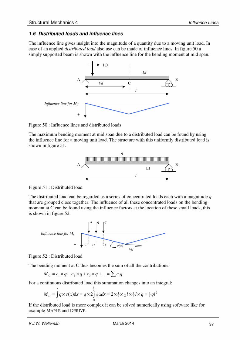
1.6 Distributed loads and influence lines
The influence line gives insight into the magnitude of a quantity due to a moving unit load. In
case of an applied distributed load also use can be made of influence lines. In figure 50 a
simply supported beam is shown with the influence line for the bending moment at mid span.
Figure 50 : Influence lines and distributed loads
The maximum bending moment at mid span due to a distributed load can be found by using
the influence line for a moving unit load. The structure with this uniformly distributed load is
shown in figure 51.
Figure 51 : Distributed load
The distributed load can be regarded as a series of concentrated loads each with a magnitude q
that are grouped close together. The influence of all these concentrated loads on the bending
moment at C can be found using the influence factors at the location of these small loads, this
is shown in figure 52.
Figure 52 : Distributed load
The bending moment at C thus becomes the sum of all the contributions:
qcqcqcqcM iC ∑=+×+×+×= ...321
For a continuous distributed load this summation changes into an integral:
2
81
21
41
21
0
21
0
22d)(2
1
qlqlldxxqxxcqM
ll
C =××××=×=×= ∫∫
If the distributed load is more complex it can be solved numerically using software like for
example MAPLE and DERIVE.
l
½l
EI
C A B
1,0
Influence line for MC
+
l
EI
A B
q
Influence line for MC
+
q q q
c1 c2 c3
¼l c(x)

Structural Mechanics 4 Influence Lines
Ir J.W. Welleman March 2014 38
1.7 The most unfavourable position of the load
Using influence lines it is possible to find for a specific quantity the most unfavourable
position of the load. If this is possible for a single load then this is also possible for a set of
loads or an infinite set of loads, the distributed load. In this paragraph we will first look at the
most unfavourable position of the above mentioned loads. As a starting point we will use the
statically determinate structure shown in figure 53. In this figure we have already drawn
several influence lines. Check the correctness of these influence lines.
Figure 53 : Statically determinate structure with influence lines
Unit load
Using these influence lines the position for which the quantity reaches its maximum value can
be read. To determine for example the maximum support reaction at A the load has to be
applied at the left end of the left cantilever.
Uniformly distributed load
A uniformly distributed load is
nothing more than a set of
concentrated loads packed
closely together. To determine
for example the maximum
support reaction at A due to a
distributed load the distributed
load has to be applied over the
entire part of the structure
where the influence line is
positive (below the axis). This
is shown in figure 54.
Figure 54 : Maximum AV due to a distributed load
4,0 m 2,0 m 2,0 m
1,0
EI
A B C
1,0
Influence
line for AV
1,5 +
q
Assumption:
Positive support reaction acts
upwards.
4,0 m 2,0 m 2,0 m
1,0
EI
A B C
1,0
1,0
0,5
0,5
Influence
line for AV
Influence
line for MC
Influence
line for VC
1,5 +
+
+
1,0
1,0
1,0

Structural Mechanics 4 Influence Lines
Ir J.W. Welleman March 2014 39
The vertical support reaction at A can be found with:
∫ ×=0,6
0
A d)( xxcqR
In this case the integral is equal to the area of the triangular area of the influence line
multiplied with the magnitude of the distributed:
qqR 5,45,10,65,0maxA =×××=
Check this answer also based up on equilibrium.
The use of influence lines to find the most unfavourable positions of distributed loads is also
illustrated with the example in figure 55 in which a braced frame is shown. To find the
unfavourable position of distributed loads for the bending moment at Z first the influence line
for the bending moment at Z is sketched. To find this influence line a unit rotation is applied
at a hinge which is positioned at Z and with a simple frame analysis the deflection xx can be
found which represents the influence factor. From this the spans with maximum loading
become clear as is indicated in figure 55.
Figure 55 : Most unfavourable position of the vertical distributed load for MZ
Load systems
Load systems are multiple (mobile) concentrated load which have a fixed relative position to
each other. These systems may represent a large moving truck or a train on a bridge. In figure
56 such a load system is shown.
Figure 56 : Load system on a statically determinate beam
The influence line for the bending moment at C is shown in figure 57.
x-as
1,0 kN
8,0 m
B A C 3,0 m
z-as 3,5 m
D
1,0 m
Z
xx
Influence
line for MZ
1,0

Structural Mechanics 4 Influence Lines
Ir J.W. Welleman March 2014 40
The question is to determine the most unfavourable position of the load system for the
bending moment at C.
Figure 57 : Starting position of the load system
The most unfavourable position of the system can be found by trying a few positions. Here
the sensitiveness of the position of the load system on the bending moment will be examined.
To do so the system is put at a starting position as is shown in figure 57. Then the system is
moved over a small distance x. This displacement will increase the contribution to the bending
moment of the left concentrated load and decrease the contribution of the right concentrated
load. This results in an total influence factor of the load system which depends on x:
0,10)0,5
875,1()
0,3
875,1()( 21 ≤≤−++= x
xc
xcxc
From this expression can be seen that moving the load system by 1,0 m tot the right results in
the maximum influence factor for the load system. For this case the result is easily seen. The
slope of the left part is steeper than the right part. By moving the system to the right we
increase the contribution of the left load more than we decrease the contribution of the right
load. The maximum influence of the left load is therefore the most unfavourable position of
the load system. This approach can be summarised as follows:
Increase of the influence = total load left × 1,875/3,0
Decrease of the influence = total load right × 1,875/5,0
For load systems consisting of two concentrated loads the most unfavourable position can
quite quickly be seen. It becomes slightly more difficult if the system consists of three
concentrated loads. The approach described here is still applicable though. For further
explanation of this we refer to EM-1-E paragraph 16.3.2.
8,0 m 3,5 m
+ δδδδθθθθ = 1,0
c2=1,875
2,1875
1,0 kN 1,0 m 2,0 m
x
c1=1,25

Structural Mechanics 4 Influence Lines
Ir J.W. Welleman March 2014 41
1.8 Exercises
Exercise 1
A hinged beam structure is shown in the figure below. The beam is fully clamped at C and
has two hinges S1 and S2.
a) Construct the influence line for the clamping moment at C
b) Construct the influence line for the shear force just right of B
c) Sketch the influence line for the deflection of hinge S2
remark : Construct means that the influence line must also be determined
quantitatively. Sketch means that the influence line must be determined
qualitatively where it also has to be clear whether the lines are straight or
curved.
Exercise 2
Another hinged beam structure is give in the figure below. The beam is fully clamped at C
and has one hinge S1.
a) Sketch the influence line for the moment at C
b) Sketch the influence line for the shear force just to the right of B
2,0 m 3,0 m 2,0 m 3,0 m
C S2 B A
S1
2,0 m 3,0 m 5,0 m
C B A
S1

Structural Mechanics 4 Influence Lines
Ir J.W. Welleman March 2014 42
Exercise 3
A hinged beam structure is shown in the figure below. The beam is clamped at A and B and
has two hinges S1 and S2. The influence of the axial deformation may be neglected.
a) Construct the influence line for the bending moment at A
b) Construct the influence line for the shear force halfway between S1-S2
c) Sketch the influence line for the deflection of hinge S2
remark : Construct means that the influence line must also be determined
quantitatively. Sketch means that the influence line must be determined
qualitatively where it also has to be clear whether the lines are straight or
curved.
Exercise 4
In the figure below a frame structure is given which consists of a beam on a column. The
beam is loaded with a downwards acting uniformly distributed load q.
a) Sketch the influence line for the bending moment at point G at mid span of AE.
b) Find the most unfavourable position of the distributed load q for the bending moment
at G.
c) Describe how the magnitude of this maximum bending moment can be determined
(qualitative approach)
3,0 m 4,0 m 3,0 m
B S2 A S1
C D
A
B
E
G

Structural Mechanics 4 Influence Lines
Ir J.W. Welleman March 2014 43
Exercise 5
A hinged beam structure is given in the figure below.
Find the influence lines for:
a) The vertical support reaction at B
b) The shear force at D
c) The bending moment at D
d) The most unfavourable position of the uniformly distributed load q for the above
quantities.
e) The corresponding extreme values of the quantities for this distributed load.
3a a a 3a
q kN/m
S
A B
C D

Structural Mechanics 4 Influence Lines
Ir J.W. Welleman March 2014 44
ANSWERS
2,0 m 3,0 m 2,0 m 3,0 m
C S2 B A
S1
1,0
Influence
line for MC
Influence line
for VB-right 1,0 1,5
Influence
line for wS-2
F=1,0 straight
straight
curved
2,0 m 3,0 m 5,0 m
C B A
S1
Influence
line for MC
1,0 curved
straight straight
Influence line
for VB-right
1,0
straight straight curved
3,0
4,5

Structural Mechanics 4 Influence Lines
Ir J.W. Welleman March 2014 45
3,0 m 4,0 m 3,0 m
B S2 A S1
Influence
line for MA
1,0
Influence
line for VS1-S2
0,5
0,5
Influence
line for wS2
F=1,0
straight
straight
curved
C D
A
B
E
G
Influence
line for MG
(top beam) 1,0
Total bending moment is equal to area
under the influence line times the
magnitude of the load q.

Structural Mechanics 4 Influence Lines
Ir J.W. Welleman March 2014 46
3a a a 3a
q kN/m
S
A B
C D
Influence
line for BV
BV
1,0
1,25
Influence
line for VD
0,25
0,75
0,25
Influence
line for MD 1,0 0,75 a
0,75 a Please note:
• Rewrite the unit rotation at D to a
deflection (position of the
mechanism)
• 2 options for the position of the
distributed load (left half or right
half since this has no influence on
the absolute value of the bending
moment at D) 231
max 2 24 0,75M a a q qa= × × × =
Maximum shear force: 1
max 2
1312 8
4 0,25
3 0,75
V a q
a q qa
= × × × +
× × × =

Structural Mechanics 4 Influence Lines
Ir J.W. Welleman March 2014 47
1.9 APPENDIX
Müller-Breslau’s method was introduced in 1886 to determine the influence lines of force
quantities. In this appendix the method is proven based on the continuous beam on three
supports for which we will determine the influence line of one of the support reactions. The
beam is shown in the figure below:
To find the support reaction at B due to a unit load at location x an auxiliary statically
determinate system is used in which the support at B is removed and the support reaction RB
is taken as an unknown load. The compatibility condition is a zero deflection at B from which
the unknown support reaction RB can be obtained.
Using Maxwell’s notation with influence factors this condition can be written as:
B
B B
= 0
1,0 0
bb bx
bb bx
w w w
w c R c
+ =
= + × =
The support reaction RB in B due to a unit load at x follows from:
B = 1,0bx
bb
cR
c− ×
Using Maxwell’s reciprocal theoreme bx xbc c= finally results in:
B = 1,0xb
bb
cR
c− ×
b a
EI
C A B
1,0
x
C A B
wbx
1,0
x
C A B
wbb
RB

Structural Mechanics 4 Influence Lines
Ir J.W. Welleman March 2014 48
This expression is in fact the influence line for the support reaction at B. The influence factor
depends on the variable x and is equal to:
xb
bb
c
c−
Apart from a scaling factor, this influence factor is equal to cxb which is the influence factor
for the deflection at x due to a load at B. In word, the deflection line of the statically
determinate system due to a unit load at B. The exact values of the influence factor have not
yet been determined but it must hold that:
xb xb
bb bb
c w
c w− = −
since:
B
B
bb bb
xb xb
w c R
w c R
= ×
= ×
The influence factor for the support reaction is a ratio that is independent of the value RB. If in
the above expression we choose for the scaling factor wbb a unit displacement the influence
factor becomes:
1,0
xb xbxb
bb
w ww
w
− −= = −
Expressed in words the above equation states that the influence factor for the support reaction
in B is equal to minus the deformed shape of the statically determinate system we have
chosen due to a unit displacement applied at the point of the force quantity we are looking at.
This is exactly what the principle of Müller-Breslau states; release the associated degree of
freedom and apply a unit displacement or rotation.
The minus sign in the expression arises from the assumed positive direction of the chosen
unknown RB. This is done deliberately to conform directly to the notation as introduced by
Maxwell. It should be clear that if the unknown (the support reaction at B) was chosen to be
positive if acting upwards combined with a positive (downwards) acting unit displacement the
minus sign would disappear from the above expression. In that case we let the requested force
quantity perform negative work which is in accordance to the approach we have presented
earlier for Müller-Breslau’s:
Apply a unit displacement that corresponds to the force quantity you are
investigating, such that the force quantity performs negative work. The deformed
structure is the influence line you are looking for. The quantity is positive for
displacements in the direction of the unit load.