Notes for chapter 4 · Notes for chapter 4 ... the form ˚= cx4=3, where cis a constant. Find the...
50
Notes for chapter 4 86 The curl operator in terms of the field’s components Fixing a Cartesian coordinate system, we find how to express the curl’s components in terms of the derivatives of the field’s components with respect to the coordinates. Because we want the curl to be a kind of first derivative operator, we expect it to depend only on the derivatives of the field’s compo- nents with respect to the coordinates. The field has three components, and there are three coordinates that we can differentiate with re- spect to, so there are nine possible partial derivatives that could consider. Because the curl is intended to be a kind of derivative, and derivatives are additive, we can isolate these partial derivatives from each other and add them. E.g., it’s conceivable (although not true, as we’ll see shortly) that the y compo- nent of the curl is 3∂E x /∂x - 7∂E y /∂z , but we don’t have to consider possibilities such as sin(∂E y /∂x). The partial derivative ∂E x /∂x contributes to the divergence, but it can’t contribute to the curl because of symmetry. For example, in the field x ˆ x, this is the only partial derivative that would be nonzero, but by symmetry the curl- meter won’t rotate when placed in this field. By rotational invariance, we can immediately conclude that there is no contribution from the other “self” terms, ∂E y /∂y and ∂E z /∂z . Visualizing the field yˆ z with a curl-meter and applying the right-hand rule, we can tell that its curl must have a positive x component. Up until now we have never specified the units of the curl-meter, but now we need to decide. We define the curl so that the result in this case is +1, so that ∂E z /∂y occurs in the expres- sion for the x component of the curl. Similar reasoning produces the term -∂E y /∂z . A cyclic permutation of x , y , and z . The remainder of the result follows from ro- tational invariance. It is possible to take the x, y, and z axes and rotate them rigidly in the manner shown in the figure, called a cyclic permutation. Therefore if a derivative like ∂E z /∂y occurs in the x component of the curl, then we must have the others obtained from it by cyclic permutation, such as ∂E x /∂z in the y component. The result is: (curl E) x = ∂E z ∂y - ∂E y ∂z (curl E) y = ∂E x ∂z - ∂E z ∂x (curl E) z = ∂E y ∂x - ∂E x ∂y . 91 No charge on the interior of a con- ductor For a conductor in equilibrium, any charge is on its surface, never in its interior. The proof of this assertion is essentially Earn- shaw’s theorem (example 11, p. 62). Suppose that a particle with charge q is in the con- ductor. For concreteness, let’s say q is posi- tive. By assumption, this charge is in a stable equilibrium. If the charge is at the surface, then this equilibrium can be created by both (1) the electric field, and (2) the force that keeps charges from getting out through the surface. But if the charge is in the interior, then only electrical forces can be involved, not other forces of type 2; this is essentially what Notes for chapter 4 101
Transcript of Notes for chapter 4 · Notes for chapter 4 ... the form ˚= cx4=3, where cis a constant. Find the...
Notes for chapter 486 The curl operator in terms of thefield’s components
Fixing a Cartesian coordinate system, we findhow to express the curl’s components in termsof the derivatives of the field’s componentswith respect to the coordinates.
Because we want the curl to be a kind of firstderivative operator, we expect it to dependonly on the derivatives of the field’s compo-nents with respect to the coordinates. Thefield has three components, and there are threecoordinates that we can differentiate with re-spect to, so there are nine possible partialderivatives that could consider. Because thecurl is intended to be a kind of derivative,and derivatives are additive, we can isolatethese partial derivatives from each other andadd them. E.g., it’s conceivable (although nottrue, as we’ll see shortly) that the y compo-nent of the curl is 3∂Ex/∂x − 7∂Ey/∂z, butwe don’t have to consider possibilities such assin(∂Ey/∂x).
The partial derivative ∂Ex/∂x contributes tothe divergence, but it can’t contribute to thecurl because of symmetry. For example, in thefield xx, this is the only partial derivative thatwould be nonzero, but by symmetry the curl-meter won’t rotate when placed in this field.By rotational invariance, we can immediatelyconclude that there is no contribution from theother “self” terms, ∂Ey/∂y and ∂Ez/∂z.
Visualizing the field yz with a curl-meter andapplying the right-hand rule, we can tell thatits curl must have a positive x component. Upuntil now we have never specified the units ofthe curl-meter, but now we need to decide. Wedefine the curl so that the result in this caseis +1, so that ∂Ez/∂y occurs in the expres-sion for the x component of the curl. Similarreasoning produces the term −∂Ey/∂z.
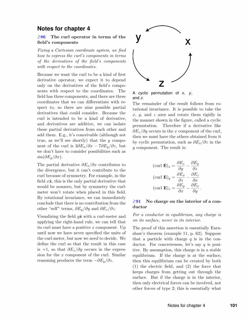
A cyclic permutation of x , y ,and z.The remainder of the result follows from ro-tational invariance. It is possible to take thex, y, and z axes and rotate them rigidly inthe manner shown in the figure, called a cyclicpermutation. Therefore if a derivative like∂Ez/∂y occurs in the x component of the curl,then we must have the others obtained from itby cyclic permutation, such as ∂Ex/∂z in they component. The result is:
(curl E)x =∂Ez∂y− ∂Ey
∂z
(curl E)y =∂Ex∂z− ∂Ez
∂x
(curl E)z =∂Ey∂x− ∂Ex
∂y.
91 No charge on the interior of a con-ductor
For a conductor in equilibrium, any charge ison its surface, never in its interior.
The proof of this assertion is essentially Earn-shaw’s theorem (example 11, p. 62). Supposethat a particle with charge q is in the con-ductor. For concreteness, let’s say q is posi-tive. By assumption, this charge is in a stableequilibrium. If the charge is at the surface,then this equilibrium can be created by both(1) the electric field, and (2) the force thatkeeps charges from getting out through thesurface. But if the charge is in the interior,then only electrical forces can be involved, notother forces of type 2; this is essentially what
Notes for chapter 4 101

we mean by saying that the substance is a con-ductor. The electric field acting on q would bethe field contributed by all the other charges,not by q itself (65). But now everythingplays out as in the original argument prov-ing Earnshaw’s theorem: a stable equilibriumwould require div E < 0, Gauss’s law forbidsthis negative divergence from being created byexternal sources.
102 Chapter 4 The electric potential

Problem 1.
Problem 2.
ProblemsKey√
A computerized answer check is available online.? A difficult problem.
1 The figure shows two climbing routes at Tahquitz Rock, nearIdyllwild, California. They begin and end at the same point. Com-pare the work done against gravity by the same climber climbingthe two routes. Why would it be of interest to state these figuresinstead as the work per kilogram of body mass, in units of J/kg?In the analogy with electrical fields, what would these units be?
. Solution, p. 425
2 The figure shows a rock climbing route lying in a vertical plane.It can be approximated by two line segments. Superimposed on theclimb is a grid of squares with sides of length `. The gravitationalfield is g.(a) Continuing the gravitational analogy from problem 1, find φB −φA and φC−φB, where the “electric potential” φ is the gravitationalpotential energy per unit mass.
√
(b) In the electrical version of this situation, the “height” is not aphysical distance in space at all, so we could say that only the hori-zontal segments of the squares represent distances, and the situationis effectively one-dimensional. Find the ratio of the “electric fields”EBC/EAB.
√
(c) In electromagnetism, we can always add an arbitrary constantto the potential while still describing the same physical situation.What would be the analogous statement for the climber in our gravi-ational analogy?
3 A hydrogen atom is electrically neutral, so at large distances,we expect that it will create essentially zero electric field. This isnot true, however, near the atom or inside it. Very close to theproton, for example, the field is very strong. To see this, think ofthe electron as a spherically symmetric cloud that surrounds theproton, getting thinner and thinner as we get farther away from theproton. (Quantum mechanics tells us that this is a more correctpicture than trying to imagine the electron orbiting the proton.)Near the center of the atom, the electron cloud’s field cancels outby symmetry, but the proton’s field is strong, so the total field isvery strong. The potential in and around the hydrogen atom canbe approximated using an expression of the form φ = r−1e−r. (Theunits come out wrong, because I’ve left out some constants.) Findthe electric field corresponding to this potential, and comment onits behavior at very large and very small r. . Solution, p. 425
Problems 103

4 Consider the following four potentials, which exist in someregion of the positive x axis:
φ1 = ax
φ2 = ax+ b
φ3 =a
x
φ4 =a
x+ b.
In each case, find the corresponding electric field, and give physicalinterpretations of what is going on physically and of the constantsa and b.
5 The figure shows a voltmeter being connected to a battery inthree different ways. In case some of the details are too hard to see,the readings are 1353, -1353, and 0, the rotary dial is on a 2000 mVDC scale, and the banana plug connector on the right is the onelabeled COM. Explain why these results are obtained.
. Solution, p. 425
Problem 5.
104 Chapter 4 The electric potential

Problem 8.
6 The figure shows two different field patterns.(a) In the first field pattern, suppose that moving a charge “uphill”along path ABD requires that work be done against the electric fieldin the amount of one joule per coulomb. How much work would haveto be done per unit charge along path ACD?
√
(b) In the second figure, the work per unit charge along EFH is 2J/C. What would it be along EGH?
√
(c) Can an electric potential φ be defined for field pattern a? Forb?
Problem 6.
7 The voltage difference between the ends of a AAA battery is1.5 V, and the battery’s length is 42 mm. If the electric field insideis constant, find its magnitude.
√
8 Electronic ink is a technology, used in electronic book read-ers such as the Amazon Kindle, for displaying images. The figureshows a side view of a cross-section of a small part of the screen,cutting through one row of pixels. Each pixel consists of a tinycapacitor, about 0.1 mm in height, with a capsule inside it. Thecapsule contains black and white particles of pigments which haveopposite charges. When a voltage is applied to the capacitor, theparticles sort themselves out in opposite directions. When the whiteparticles are on top, the pixel appears like white paper when viewedfrom above. When the black particles are on top, it appears like adot of black ink. An electric field of about 1.5× 10⁵ V/m is neededin order to make the particles move. Estimate the voltage that hasto be applied to the capacitor.
√
Problems 105
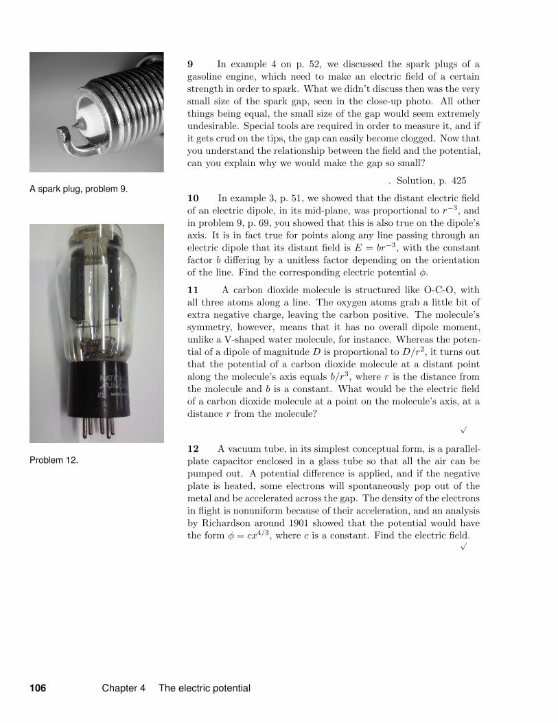
A spark plug, problem 9.
Problem 12.
9 In example 4 on p. 52, we discussed the spark plugs of agasoline engine, which need to make an electric field of a certainstrength in order to spark. What we didn’t discuss then was the verysmall size of the spark gap, seen in the close-up photo. All otherthings being equal, the small size of the gap would seem extremelyundesirable. Special tools are required in order to measure it, and ifit gets crud on the tips, the gap can easily become clogged. Now thatyou understand the relationship between the field and the potential,can you explain why we would make the gap so small?
. Solution, p. 425
10 In example 3, p. 51, we showed that the distant electric fieldof an electric dipole, in its mid-plane, was proportional to r−3, andin problem 9, p. 69, you showed that this is also true on the dipole’saxis. It is in fact true for points along any line passing through anelectric dipole that its distant field is E = br−3, with the constantfactor b differing by a unitless factor depending on the orientationof the line. Find the corresponding electric potential φ.
11 A carbon dioxide molecule is structured like O-C-O, withall three atoms along a line. The oxygen atoms grab a little bit ofextra negative charge, leaving the carbon positive. The molecule’ssymmetry, however, means that it has no overall dipole moment,unlike a V-shaped water molecule, for instance. Whereas the poten-tial of a dipole of magnitude D is proportional to D/r2, it turns outthat the potential of a carbon dioxide molecule at a distant pointalong the molecule’s axis equals b/r3, where r is the distance fromthe molecule and b is a constant. What would be the electric fieldof a carbon dioxide molecule at a point on the molecule’s axis, at adistance r from the molecule?
√
12 A vacuum tube, in its simplest conceptual form, is a parallel-plate capacitor enclosed in a glass tube so that all the air can bepumped out. A potential difference is applied, and if the negativeplate is heated, some electrons will spontaneously pop out of themetal and be accelerated across the gap. The density of the electronsin flight is nonuniform because of their acceleration, and an analysisby Richardson around 1901 showed that the potential would havethe form φ = cx4/3, where c is a constant. Find the electric field.√
106 Chapter 4 The electric potential
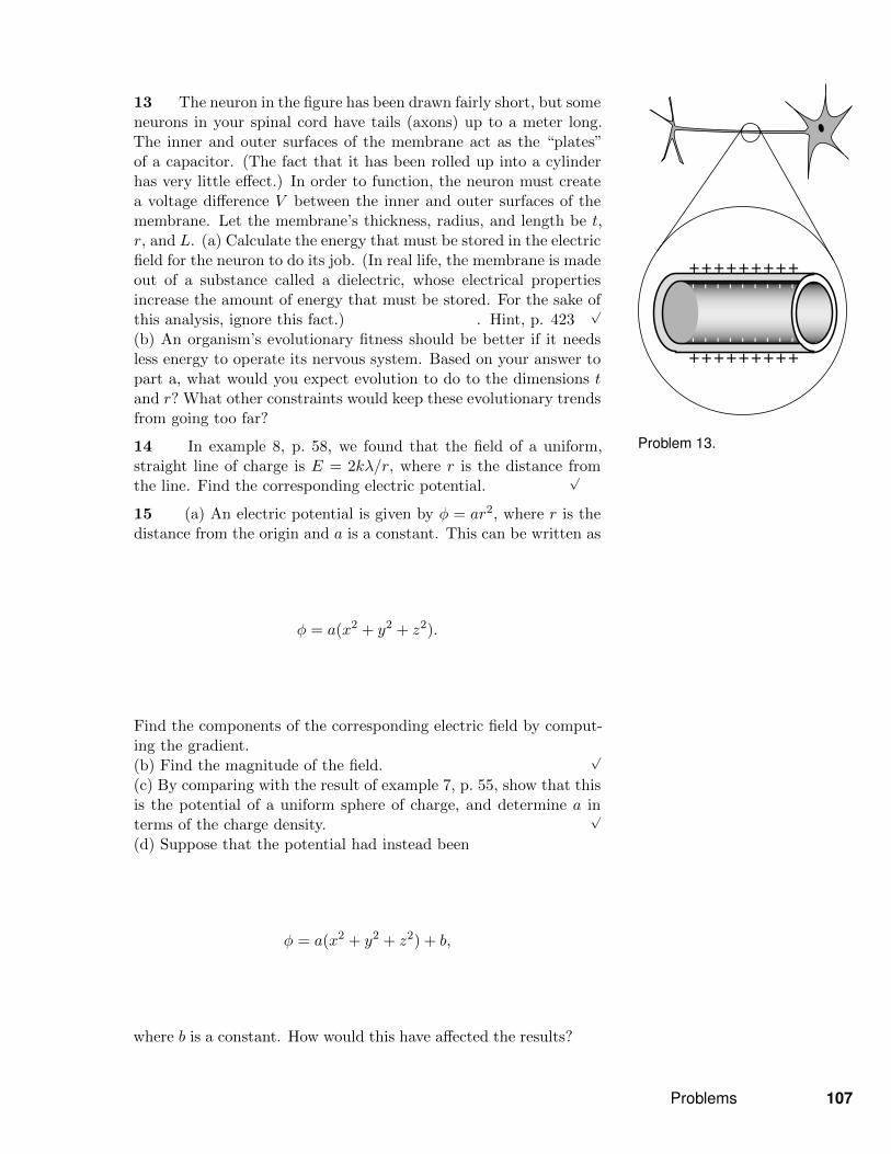
Problem 13.
13 The neuron in the figure has been drawn fairly short, but someneurons in your spinal cord have tails (axons) up to a meter long.The inner and outer surfaces of the membrane act as the “plates”of a capacitor. (The fact that it has been rolled up into a cylinderhas very little effect.) In order to function, the neuron must createa voltage difference V between the inner and outer surfaces of themembrane. Let the membrane’s thickness, radius, and length be t,r, and L. (a) Calculate the energy that must be stored in the electricfield for the neuron to do its job. (In real life, the membrane is madeout of a substance called a dielectric, whose electrical propertiesincrease the amount of energy that must be stored. For the sake ofthis analysis, ignore this fact.) . Hint, p. 423
√
(b) An organism’s evolutionary fitness should be better if it needsless energy to operate its nervous system. Based on your answer topart a, what would you expect evolution to do to the dimensions tand r? What other constraints would keep these evolutionary trendsfrom going too far?
14 In example 8, p. 58, we found that the field of a uniform,straight line of charge is E = 2kλ/r, where r is the distance fromthe line. Find the corresponding electric potential.
√
15 (a) An electric potential is given by φ = ar2, where r is thedistance from the origin and a is a constant. This can be written as
φ = a(x2 + y2 + z2).
Find the components of the corresponding electric field by comput-ing the gradient.(b) Find the magnitude of the field.
√
(c) By comparing with the result of example 7, p. 55, show that thisis the potential of a uniform sphere of charge, and determine a interms of the charge density.
√
(d) Suppose that the potential had instead been
φ = a(x2 + y2 + z2) + b,
where b is a constant. How would this have affected the results?
Problems 107
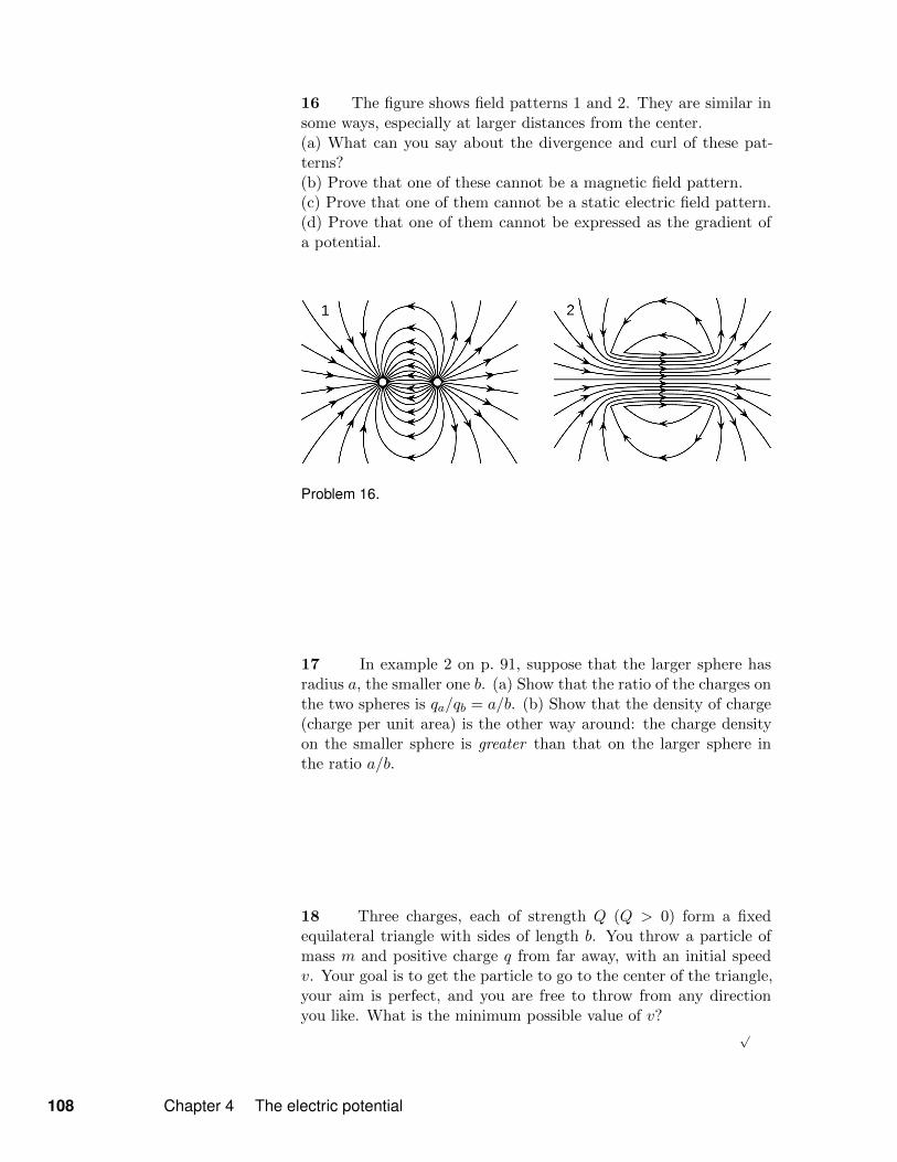
16 The figure shows field patterns 1 and 2. They are similar insome ways, especially at larger distances from the center.(a) What can you say about the divergence and curl of these pat-terns?(b) Prove that one of these cannot be a magnetic field pattern.(c) Prove that one of them cannot be a static electric field pattern.(d) Prove that one of them cannot be expressed as the gradient ofa potential.
Problem 16.
17 In example 2 on p. 91, suppose that the larger sphere hasradius a, the smaller one b. (a) Show that the ratio of the charges onthe two spheres is qa/qb = a/b. (b) Show that the density of charge(charge per unit area) is the other way around: the charge densityon the smaller sphere is greater than that on the larger sphere inthe ratio a/b.
18 Three charges, each of strength Q (Q > 0) form a fixedequilateral triangle with sides of length b. You throw a particle ofmass m and positive charge q from far away, with an initial speedv. Your goal is to get the particle to go to the center of the triangle,your aim is perfect, and you are free to throw from any directionyou like. What is the minimum possible value of v?
√
108 Chapter 4 The electric potential

Problem 19.
Problem 20.
19 The figure shows a simplified diagram of an electron gun suchas the one that creates the electron beam in a TV tube. Electronsthat spontaneously emerge from the negative electrode (cathode)are then accelerated to the positive electrode, which has a hole in it.(Once they emerge through the hole, they will slow down. However,if the two electrodes are fairly close together, this slowing down is asmall effect, because the attractive and repulsive forces experiencedby the electron tend to cancel.)(a) If the voltage difference between the electrodes is ∆V , what isthe velocity of an electron as it emerges at B? Assume that its initialvelocity, at A, is negligible.
√
(b) Evaluate your expression numerically for the case where ∆V=10kV, and compare to the speed of light. . Solution, p. 425
√
20 The figure shows a simplified diagram of a device calleda tandem accelerator, used for accelerating beams of ions up tospeeds on the order of 1-10% of the speed of light. (Since thesevelocities are not too big compared to c, you can use nonrelativisticphysics throughout this problem.) The nuclei of these ions collidewith the nuclei of atoms in a target, producing nuclear reactions forexperiments studying the structure of nuclei. The outer shell of theaccelerator is a conductor at zero voltage (i.e., the same voltage asthe Earth). The electrode at the center, known as the “terminal,” isat a high positive voltage, perhaps millions of volts. Negative ionswith a charge of −1 unit (i.e., atoms with one extra electron) areproduced offstage on the right, typically by chemical reactions withcesium, which is a chemical element that has a strong tendency togive away electrons. Relatively weak electric and magnetic forces areused to transport these −1 ions into the accelerator, where they areattracted to the terminal. Although the center of the terminal hasa hole in it to let the ions pass through, there is a very thin carbonfoil there that they must physically penetrate. Passing through thefoil strips off some number of electrons, changing the atom into apositive ion, with a charge of +n times the fundamental charge.Now that the atom is positive, it is repelled by the terminal, andaccelerates some more on its way out of the accelerator.
(a) Find the velocity, v, of the emerging beam of positive ions, interms of n, their mass m, the terminal voltage V , and fundamentalconstants. Neglect the small change in mass caused by the loss ofelectrons in the stripper foil.
√
(b) To fuse protons with protons, a minimum beam velocity of about11% of the speed of light is required. What terminal voltage wouldbe needed in this case?
√
(c) In the setup described in part b, we need a target containingatoms whose nuclei are single protons, i.e., a target made of hydro-
Problems 109
Problem 22.
Problem 24.
gen. Since hydrogen is a gas, and we want a foil for our target, wehave to use a hydrogen compound, such as a plastic. Discuss whateffect this would have on the experiment.
21 (a) A coaxial cable consists of a cylindrical inner conductorwith radius a and an outer one with radius b. If the potential dif-ference between the two conductors is ∆φ, find the electric field ata ≤ r ≤ b.
√
(b) Show that your answer makes sense when a = b and when b < a.
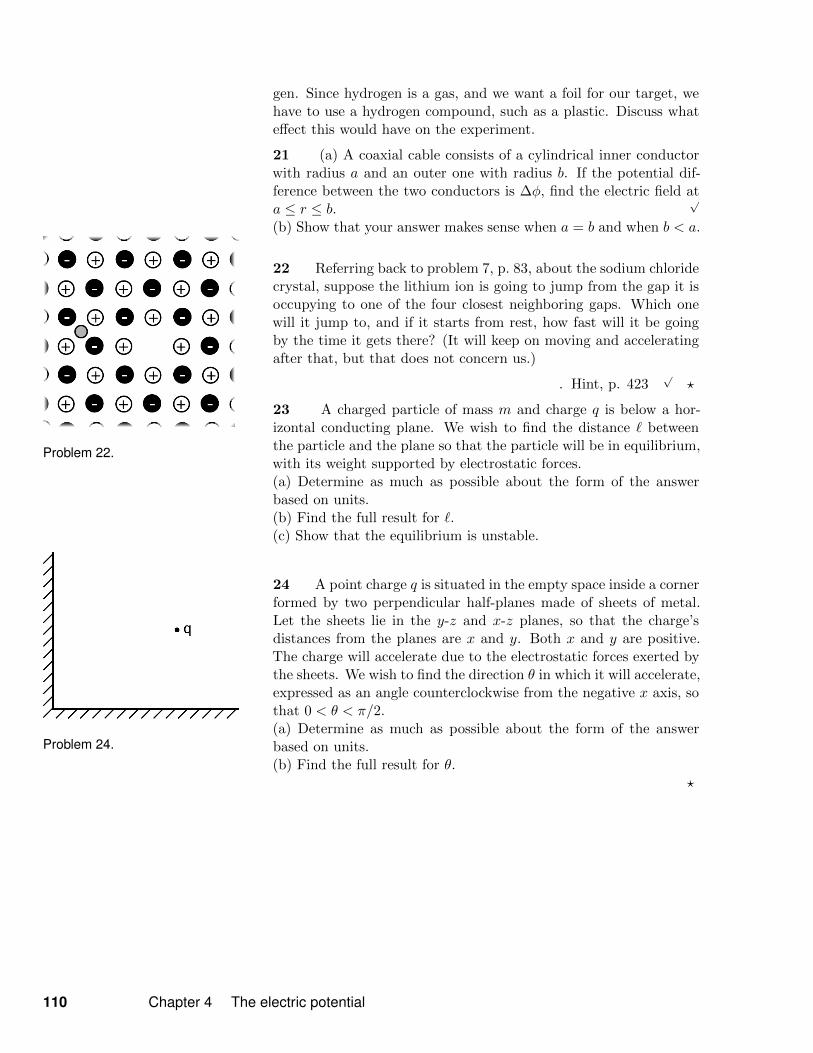
22 Referring back to problem 7, p. 83, about the sodium chloridecrystal, suppose the lithium ion is going to jump from the gap it isoccupying to one of the four closest neighboring gaps. Which onewill it jump to, and if it starts from rest, how fast will it be goingby the time it gets there? (It will keep on moving and acceleratingafter that, but that does not concern us.)
. Hint, p. 423√
?
23 A charged particle of mass m and charge q is below a hor-izontal conducting plane. We wish to find the distance ` betweenthe particle and the plane so that the particle will be in equilibrium,with its weight supported by electrostatic forces.(a) Determine as much as possible about the form of the answerbased on units.(b) Find the full result for `.(c) Show that the equilibrium is unstable.
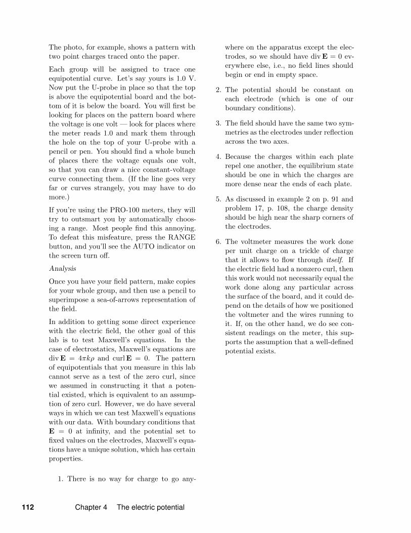
24 A point charge q is situated in the empty space inside a cornerformed by two perpendicular half-planes made of sheets of metal.Let the sheets lie in the y-z and x-z planes, so that the charge’sdistances from the planes are x and y. Both x and y are positive.The charge will accelerate due to the electrostatic forces exerted bythe sheets. We wish to find the direction θ in which it will accelerate,expressed as an angle counterclockwise from the negative x axis, sothat 0 < θ < π/2.(a) Determine as much as possible about the form of the answerbased on units.(b) Find the full result for θ.
?
110 Chapter 4 The electric potential

Minilab 4: Mapping electricfieldsApparatus
board and U-shaped probeDC power supplymultimeterstencils for drawing electrode shapes on pa-per
Goal: Visualize electric fields using equipo-tential curves.
Test Maxwell’s equations in the special case ofelectrostatics.
a / Circuit diagram.
Figure a shows a circuit diagram of the appa-ratus. The power supply provides an 8 V po-tential difference between the two metal elec-trodes, drawn in black. A voltmeter measuresthe potential difference between an arbitraryreference voltage and a point of interest in thegray area around the electrodes. The resultwill be somewhere between 0 and 8 V.
The photo in figure b shows the actual appa-ratus. The electrodes are painted with silverpaint on a detachable board, which goes un-derneath the big board. What you actually
b / Photo of the apparatus, showing a differ-ent electrode pattern (two point charges).
see on top is just a piece of paper on whichyou’ll trace the equipotentials with a pen. Thevoltmeter is connected to a U-shaped probewith a metal contact that slides underneaththe board, and a hole in the top piece for yourpen.
Turn your large board upside down. Findthe small detachable board with the parallel-plate capacitor pattern on it, and screw it tothe underside of the equipotential board, withthe silver-painted side facing down toward thetabletop. Use the washers to protect the silverpaint so that it doesn’t get scraped off whenyou tighten the screws. Now connect the volt-age source (using the provided wires) to thetwo large screws on either side of the board.Connect the multimeter so that you can mea-sure the voltage difference across the termi-nals of the voltage source. Adjust the voltagesource to give 8 volts.
If you press down on the board, you can slipthe paper between the board and the four but-tons you see at the corners of the board. Tapethe paper to your board, because the but-tons aren’t very dependable. There are plas-tic stencils in some of the envelopes, and youcan use these to draw the electrodes accuratelyonto your paper so you know where they are.
Minilab 4: Mapping electric fields 111
The photo, for example, shows a pattern withtwo point charges traced onto the paper.
Each group will be assigned to trace oneequipotential curve. Let’s say yours is 1.0 V.Now put the U-probe in place so that the topis above the equipotential board and the bot-tom of it is below the board. You will first belooking for places on the pattern board wherethe voltage is one volt — look for places wherethe meter reads 1.0 and mark them throughthe hole on the top of your U-probe with apencil or pen. You should find a whole bunchof places there the voltage equals one volt,so that you can draw a nice constant-voltagecurve connecting them. (If the line goes veryfar or curves strangely, you may have to domore.)
If you’re using the PRO-100 meters, they willtry to outsmart you by automatically choos-ing a range. Most people find this annoying.To defeat this misfeature, press the RANGEbutton, and you’ll see the AUTO indicator onthe screen turn off.
Analysis
Once you have your field pattern, make copiesfor your whole group, and then use a pencil tosuperimpose a sea-of-arrows representation ofthe field.
In addition to getting some direct experiencewith the electric field, the other goal of thislab is to test Maxwell’s equations. In thecase of electrostatics, Maxwell’s equations arediv E = 4πkρ and curl E = 0. The patternof equipotentials that you measure in this labcannot serve as a test of the zero curl, sincewe assumed in constructing it that a poten-tial existed, which is equivalent to an assump-tion of zero curl. However, we do have severalways in which we can test Maxwell’s equationswith our data. With boundary conditions thatE = 0 at infinity, and the potential set tofixed values on the electrodes, Maxwell’s equa-tions have a unique solution, which has certainproperties.
1. There is no way for charge to go any-
where on the apparatus except the elec-trodes, so we should have div E = 0 ev-erywhere else, i.e., no field lines shouldbegin or end in empty space.
2. The potential should be constant oneach electrode (which is one of ourboundary conditions).
3. The field should have the same two sym-metries as the electrodes under reflectionacross the two axes.
4. Because the charges within each platerepel one another, the equilibrium stateshould be one in which the charges aremore dense near the ends of each plate.
5. As discussed in example 2 on p. 91 andproblem 17, p. 108, the charge densityshould be high near the sharp corners ofthe electrodes.
6. The voltmeter measures the work doneper unit charge on a trickle of chargethat it allows to flow through itself. Ifthe electric field had a nonzero curl, thenthis work would not necessarily equal thework done along any particular acrossthe surface of the board, and it could de-pend on the details of how we positionedthe voltmeter and the wires running toit. If, on the other hand, we do see con-sistent readings on the meter, this sup-ports the assumption that a well-definedpotential exists.
112 Chapter 4 The electric potential
Exercise 4A: A preview of theelectric potential andmeasurement of voltagesThis exercise is meant to be done before read-ing ch. 4.
For certain types of electric fields, includingfields that don’t change over time, we can de-fine an electric potential, φ, which is a measureof electrical potential energy per unit charge.It has units of volts, 1 V=1 J/C. In a circuit,we can make an analogy with the behavior ofa fluid flowing through pipes: the flow is thecurrent, while the pressure causing the flow isthe voltage.
See figure g, p. 90, for instructions on how touse a meter to measure the difference in poten-tial between two points, ∆φ = φ2−φ1. Detailsdiffer, but meters are basically standardized.
(1) Use the meter to measure the voltage ofa battery. The battery is like a pump thatcreates a pressure difference.
(2) What happens when you do the followingthings?
• Reverse the connections.
• Connect both leads to the same terminalof the battery.
• Only connect one lead.
(3) Put two batteries in series:
This is most easily done using battery holders,alligator clips, and banana-plug cables. Mea-sure the ∆φ between the ends. The two cablesfrom the voltmeter can simply be touched tothe two ends, using them like probes; it is notnecessary to make hard connections every timeyou measure a voltage.
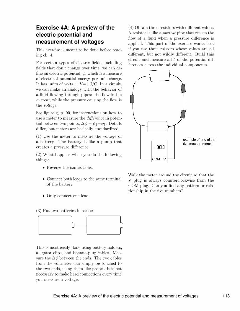
(4) Obtain three resistors with different values.A resistor is like a narrow pipe that resists theflow of a fluid when a pressure difference isapplied. This part of the exercise works bestif you use three rsistors whose values are alldifferent, but not wildly different. Build thiscircuit and measure all 5 of the potential dif-ferences across the individual components.
Walk the meter around the circuit so that theV plug is always counterclockwise from theCOM plug. Can you find any pattern or rela-tionship in the five numbers?
Exercise 4A: A preview of the electric potential and measurement of voltages 113

Exercise 4B: Charge density,field, and potential(1) A charge distribution is given by
ρ =
−a, z > b
+a, −b < z < b
−a, z < −b
(a) Use Gauss’s law to find the electric field inregion B as a function of z (not just at somespecial location such as z = b). As a bound-ary condition, we let E = 0 at z = 0, as sug-gested by the symmetry of the charge distri-bution. Without this boundary condition, wecould add any uniform field and get a differentsolution.
Similarly, find the field in region A. To savetime, it is not necessary to explicitly write outthe field in region C, because it is related bysymmetry to the field in A.
(b) Check your result by verifying that div E =4πkρ.
(c) Find the potential. You will have threeconstants of integration, two of which can bedetermined by requiring that φ be a continu-ous function.
(d) Sketch ρ, Ez, and φ as functions of z. Clas-sify these functions as even or odd.
(2) A sphere of radius R has charge q dis-tributed uniformly throughout its volume.
(a) Find the electric field. (The boundary con-dition is that E = 0 at infinity.)
(b) Find the potential.
114 Chapter 4 The electric potential

A tower and cables of the Golden Gate Bridge. The pressure and tension in the tower and cables are propertiesof the electric and magnetic fields at the atomic level.
Chapter 5
Electromagnetism
5.1 Current and magnetic fieldsAt this stage, you understand roughly as much about the classi-fication of interactions as physicists understood around the year1800. There appear to be three fundamentally different types ofinteractions: gravitational, electrical, and magnetic. Many typesof interactions that appear superficially to be distinct — stickiness,chemical interactions, the energy an archer stores in a bow — arereally the same: they’re manifestations of electrical interactions be-tween atoms. Is there any way to shorten the list any further? Theprospects seem dim at first. For instance, we find that if we rub apiece of fur on a rubber rod, the fur does not attract or repel a mag-net. The fur has an electric field, and the magnet has a magneticfield. The two are completely separate, and don’t seem to affectone another. Likewise we can test whether magnetizing a piece ofiron changes its weight. The weight doesn’t seem to change by any
115

a / 1. When no charge flowsthrough the wire, and the magnetis unaffected. It points in thedirection of the Earth’s magneticfield. 2. Charge flows through thewire. There is a strong effect onthe magnet, which turns almostperpendicular to it. If the earth’sfield could be removed entirely,the compass would point exactlyperpendicular to the wire; this isthe direction of the wire’s field.
b / A schematic representa-tion of an unmagnetized material,1, and a magnetized one, 2.
measurable amount, so magnetism and gravity seem to be unrelated.
That was where things stood until 1820, when the Danish physi-cist Hans Christian Oersted was delivering a lecture at the Univer-sity of Copenhagen, and he wanted to give his students a demon-stration that would illustrate the cutting edge of research. He useda battery to make charge flow through a wire, and held the wire neara magnetic compass. The ideas was to give an example of how onecould search for a previously undiscovered link between electricity(the charge flowing in the wire) and magnetism. One never knowshow much to believe from these dramatic legends, but the storyis that the experiment he’d expected to turn out negative insteadturned out positive: when he held the wire near the compass, thecharge flowing through the wire caused the compass to twist!
Oersted was led to the conclusion that when matter creates mag-netic fields, it happens because the matter contains moving charges.A permanent magnet, he inferred, contained moving charges on amicroscopic scale, but their motion simply wasn’t practical to detectusing human-scale measuring devices in the lab. Today this seemsnatural to us based on the planetary model of the atom. As shownin figure b, a magnetized piece of iron is different from an unmagne-tized piece because the atoms in the unmagnetized piece are jumbledin random orientations, whereas the atoms in the magnetized pieceare at least partially organized to face in a certain direction.
Not until later in this book will we get into the mathematical andgeometrical details of the magnetic fields created by moving charges.However, we can immediately make some far-reaching conclusions.Figure c/1 shows, in a cartoonish way, the fact that a line of positivecharges, at rest, makes an electric field in the surrounding space. Ifwe approximate the charges as a continuous line with no gaps, thenthe electric field is one we have already studied in sec. 2.7, p. 58: itpoints outward, and its magnitude is proportional to 1/r, where ris the distance from the line.
But now let’s switch to a different frame of reference, as in fig-ure c/2. In this frame, the charges are moving, so there is bothan electric field and a magnetic field. We are led to the followingimportant conclusion:
ElectromagnetismA certain mixture of electric and magnetic fields will be measuredas a different mixture by an observer in a different state of motion.
This shows that electric and magnetic fields are not entirely sep-arate things, but are instead two sides of the same coin. The con-clusion holds regardless of whether matter is present. For thesereasons, the entire subject of electricity and magnetism is often re-
116 Chapter 5 Electromagnetism

c / 1. A line of positive chargesis at rest. There is an electricfield. 2. In a different frame ofreference, the same chargesare seen as moving to the right.There is both an electric field anda magnetic field.
d / A salt crystal, example 1.
ferred to by the term electromagnetism. We often refer loosely to“the electromagnetic field,” meaning both E and B collectively.
In the language of section 2.6.2, p. 56, the fields are not invari-ant quantities. They depend on the frame of reference, as do othermore familiar quantities such as velocity. When we want to converta velocity vector from one frame of reference to another, we havea rule for doing so, which is simple vector addition. In fancy lan-guage, this is called “transforming” the velocity vector. The rulesfor transforming electric and magnetic fields are more complicated,and we will postpone discussing them until sec. 7.1, p. 173. How-ever, one thing we can say about the transformations is that theymust be additive, because the laws of physics obey the principle ofsuperposition, and we want the laws of physics to be equally validin all frames of reference.
By the way, the concepts that we are describing using the words“superposition” and “additive” are usually referred to by mathe-maticians using the terms “linearity” and “linear.” For example, amathematician would describe the derivative rule (f + g)′ = f ′ + g′
from freshman calculus as the linearity of the derivative.
Throwing salt doesn’t make a magnet example 1Figure d shows a salt crystal. The smaller, darker spheres aresodium atoms. Bigger, lighter ones are chlorine. When these dis-parate atoms assemble themselves into a solid, some charge istransferred from the chlorines to the sodiums. This is essentiallythe same thing that is going on in static electricity examples suchas the sticky tape in figure a, p. 41: different substances “likeelectrons” to different extents, so when they are put in contact,one steals from the other.
In the frame of reference where the crystal is at rest, it has an out-ward electric field E1 due to the sodiums and an inward field E2from the chlorines. These two fields are theoretically incredibly in-tense, but due to superposition, they almost exactly cancel at themacroscopic scale, and cannot be detected outside the crystal.(At the microscopic scale, where it is evident that the positive andnegative charge distributions aren’t exactly the same, the cancel-lation fails, and there are intense fields. These fields are whathold the crystal together.)
If we throw the salt crystal, then the field E1 of the sodiums trans-forms to some mixture of an electric field plus a magnetic fieldB1, and similarly we have a B2 from the chlorines. But becauseE1 + E2 = 0, and because the transformation is additive, we haveB1 + B2 = 0 as well, and no observable magnetic field is pro-duced.
Magnetic field of a wire example 2Since the electric field in c/1 is proportional to 1/r (sec. 2.7 and
Section 5.1 Current and magnetic fields 117

e / Example 2, the magneticfield of a wire with charge flowingthrough it. The field pattern isshown in the plane perpendicularto the wire. The orientation isrotated by 90 degrees relative tofigure c. The white circle at thecenter is the cross-section of thewire.
f / Right-hand rule for the di-rection of the magnetic fieldcreated by the current in astraight wire.
example 8, p. 58), the electric and magnetic fields in c/2 are alsoproportional to 1/r .
Now consider a wire such as the one in figure a/2. Such a wireis electrically neutral, containing equal numbers of positive andnegative charges. In the condition where charge is flowing, thecharges of one sign are standing still while the ones with the othersign move. (In a metal wire, the moving charges are the electronsand the stationary ones are the nuclei.) This is essentially thesituation in figure c/2, except that the electric fields cancel out,leaving a purely magnetic field. We conclude that when chargesflow through a wire, the magnetic field surrounding the wire isproportional to 1/r . We’ll work out the constants of proportionalityin example 6 on p. 179.
What is the direction of this field? It is not hard to show basedon symmetry arguments that the radial component of the fieldmust be zero (137), and this is also suggested by Oersted’sexperimental evidence (figure a, p. 116). Rather, the magneticfield circulates around the wire as shown in figure e.
In cases such as example 2, we find that the magnetic field de-pends only (137) on an electrical quantity called the current, de-fined as the number of coulombs per second that flow past a givenpoint. As with a river or a pipe carrying water, the same currentcould be created by a large amount of charge moving slowly, or asmall amount with a high velocity. Current is notated I, and isdefined formally as
I =dq
dt.
Its units are normally abbreviated as amperes (“amps”), 1 A=1 C/s.
self-check AWhy are the field lines in figure e unevenly spaced? . Answer, p. 429
In figure e, there was no obvious reason why the magnetic fieldshould have been counterclockwise rather than clockwise. This de-pends on the direction of the current, as shown in figure f. Thefact that we use a right-hand rule for this is clearly nothing basicabout physics — the right hand was chosen because humans aremostly right-handed. There are actually two arbitrary conventionsbehind this, which we encountered in sec. 2.1.1, p. 41. First, BenFranklin arbitrarily choose one type of charge q to call positive andone to call negative, and this also implies a definition of the sign ofthe current dq/dt. Second, someone had to resolve the ambiguitybetween defining the magnetic field to be our civilization’s B, or in-stead −B. Given these two arbitrary choices, we get the right-handrule illustrated in the figure.
A straight wire like the one in figure e is not usually a veryefficient or compact way of making a strong magnetic field. A more
118 Chapter 5 Electromagnetism
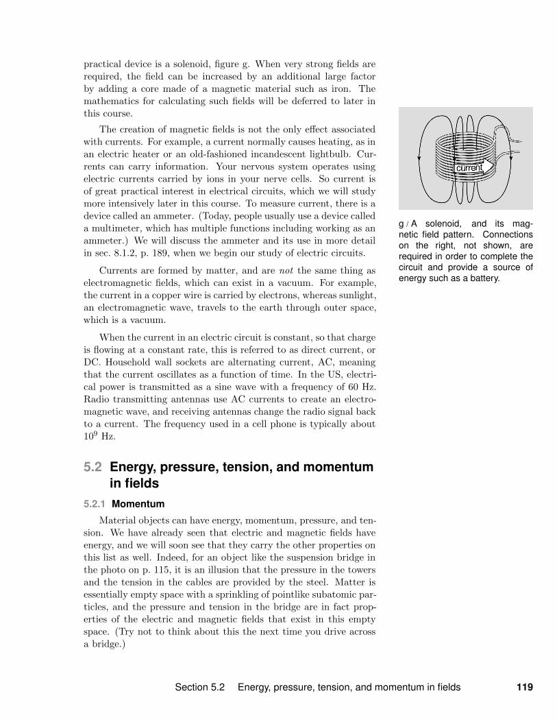
g / A solenoid, and its mag-netic field pattern. Connectionson the right, not shown, arerequired in order to complete thecircuit and provide a source ofenergy such as a battery.
practical device is a solenoid, figure g. When very strong fields arerequired, the field can be increased by an additional large factorby adding a core made of a magnetic material such as iron. Themathematics for calculating such fields will be deferred to later inthis course.
The creation of magnetic fields is not the only effect associatedwith currents. For example, a current normally causes heating, as inan electric heater or an old-fashioned incandescent lightbulb. Cur-rents can carry information. Your nervous system operates usingelectric currents carried by ions in your nerve cells. So current isof great practical interest in electrical circuits, which we will studymore intensively later in this course. To measure current, there is adevice called an ammeter. (Today, people usually use a device calleda multimeter, which has multiple functions including working as anammeter.) We will discuss the ammeter and its use in more detailin sec. 8.1.2, p. 189, when we begin our study of electric circuits.
Currents are formed by matter, and are not the same thing aselectromagnetic fields, which can exist in a vacuum. For example,the current in a copper wire is carried by electrons, whereas sunlight,an electromagnetic wave, travels to the earth through outer space,which is a vacuum.
When the current in an electric circuit is constant, so that chargeis flowing at a constant rate, this is referred to as direct current, orDC. Household wall sockets are alternating current, AC, meaningthat the current oscillates as a function of time. In the US, electri-cal power is transmitted as a sine wave with a frequency of 60 Hz.Radio transmitting antennas use AC currents to create an electro-magnetic wave, and receiving antennas change the radio signal backto a current. The frequency used in a cell phone is typically about109 Hz.
5.2 Energy, pressure, tension, and momentumin fields
5.2.1 Momentum
Material objects can have energy, momentum, pressure, and ten-sion. We have already seen that electric and magnetic fields haveenergy, and we will soon see that they carry the other properties onthis list as well. Indeed, for an object like the suspension bridge inthe photo on p. 115, it is an illusion that the pressure in the towersand the tension in the cables are provided by the steel. Matter isessentially empty space with a sprinkling of pointlike subatomic par-ticles, and the pressure and tension in the bridge are in fact prop-erties of the electric and magnetic fields that exist in this emptyspace. (Try not to think about this the next time you drive acrossa bridge.)
Section 5.2 Energy, pressure, tension, and momentum in fields 119
Summary of energy and mo-mentum densities
dUE =1
8πkE2 dv
dUB =c2
8πkB2 dv
dp =1
4πkE×B dv
There is a reason that we discussed the energy density of fieldsway back in chapter 1, but are only now getting to the momentumdensity. This is because, for straightforward mathematical reasons,momentum can never be carried by a pure electric or pure magneticfield, but only by a combination of both. That is, the momentumdensity is an electromagnetic property. To see this, consider the factthat we have only two ways of multiplying vectors: the dot product,which is a scalar, and the cross product, which is a vector. (Theseoperations were reviewed in sec. 1.3.6, p. 25.) Energy is a scalar,so it makes sense that the energy in the fields goes like E · E andB · B, i.e., like the squared magnitudes of the fields. Momentumis a vector, so the momentum density must be a cross product ofthe fields. But the cross product of parallel vectors is always zero,so expressions like E × E and B × B vanish identically and areuseless for our purposes. The momentum density must therefore beproportional to E × B, so it is a joint property of the two fields.Filling in the correct constant of proportionality, which we’ll comeback to in a moment, it turns out that the momentum is given by
dp =1
4πkE×B dv.
The argument given above only demonstrated that the momen-tum density had to be proportional to E ×B, but it didn’t fix theproportionality constant of c2/4πk. The c2/k has to be there be-cause of units, but we might wonder why the unitless factor isn’tsimply zero rather than 1/4π. After all, we don’t notice this momen-tum in everyday life; for example, when we turn on a flashlight, itdoesn’t recoil like a gun. The answer is that the physical quantitieson the list we’ve been discussing — energy, momentum, pressure,and tension — are not independent things. They’re all intimatelyrelated. For example, if we want to change the kinetic energy ofa car, we have to change its momentum as well (137). If a radiosignal comes along and pumps kinetic energy into the electrons inthe antenna of your phone, then it’s also transferring momentum tothem, and therefore it must have some momentum itself.
It is in fact plausible that the proportionality constant occurringin the equation for the momentum density is such that the momen-tum of light is too small to notice in everyday life. For materialobjects moving at speeds small compared to c, the kinetic energyand momentum are given by K = (1/2)mv2 and p = mv, so thatthe ratio of momentum to energy is p/K = 2/v. Therefore objectsmoving very fast have very little momentum in proportion to theirenergy. We see this, for example, in an old-fashioned CRT televisiontube, in which the electron beam moves at extremely high speeds(perhaps 106 m/s); the energy is enough to make a bright image onthe screen, but the device doesn’t recoil from the beam’s momen-tum when we turn it on, nor does it shake and rattle as the the
120 Chapter 5 Electromagnetism

h / Halley’s comet, example3.
i / Example 4.
beam is steered back and forth across the screen to paint the pic-ture. Although the equations above do not actually hold in detail forlight (the final result ends up being off by a factor of 2, as shown insec. 6.6.1, p. 157), it still makes sense that the momentum-to-energyratio is extremely small, because the speed, c, is so big.
A comet’s tail example 3Halley’s comet, shown in figure h, has a very elongated elliptical
orbit, like those of many other comets. About once per century,its orbit brings it close to the sun. The comet’s head, or nucleus,is composed of dirty ice, so the energy deposited by the intensesunlight gradually removes ice from the surface and turns it intowater vapor.
The sunlight does not just carry energy, however. If it only carriedenergy, then the water vapor would just form a spherical halo thatwould surround the nucleus and travel along with it. The light alsocarries momentum. Once the steam comes off, the momentum ofthe sunlight impacting on it pushes it away from the sun, forminga tail as shown in in the top image. (Some comets also have asecond tail, which is propelled by electrical forces rather than bythe momentum of sunlight.)
The Nichols radiometer example 4Figure i shows a simplified drawing of the 1903 experiment byNichols and Hull that verified the predicted momentum of lightwaves. Two circular mirrors were hung from a fine quartz fiber,inside an evacuated bell jar. A 150 mW beam of light was shoneon one of the mirrors for 6 s, producing a tiny rotation, whichwas measurable by an optical lever (not shown). The force waswithin 0.6% of the theoretically predicted value of 0.001 µN. Forcomparison, a short clipping of a human hair weighs ∼ 1 µN.
The hydrogen bomb example 5The technological feasibility of the hydrogen bomb was consid-ered uncertain for some time after the end of World War II. Thegeneral idea was to use a fission bomb to implode hydrogen fueland create conditions of high temperature and density in orderto initiate nuclear fusion reactions. If a few properties of certainnuclei had been slightly different, the human race might not havebeen afflicted with this weapon. The first successful design con-cept was created in 1951 by Stanislaw Ulam and Edward Teller,both of them Jewish refugees whose moral and political calculusanalogized Stalin to Hitler. A crucial trick was the use of radiationpressure from x-rays to implode the hydrogen fuel. Although thispressure was smaller than the pressure of the imploding materialparticles, the radiation traveled faster and got to the fuel first.
Because the momentum of light waves is so small in cases likeexamples 3 and 4, one might wonder why we should even bother dis-
Section 5.2 Energy, pressure, tension, and momentum in fields 121

j / Pressure and tension in thefield of a parallel-plate capacitor.Side view.
cussing it. Is it purely an impractical and theoretical consideration?The answer is that it is very practical in the sense that it helps usto understand important practical facts about these waves.
One such fact is that disturbances in the electric and magneticfields are never purely electric waves or magnetic waves. They carrymomentum, and therefore they must contain an oscillation of bothfields. This is why phenomena like light and radio waves are referredto as electromagnetic waves.
We can also see that such waves must have fields with nonvan-ishing components perpendicular to the direction in which the waveis traveling, because the cross product E × B is perpendicular toboth E and B. In fact, for the simplest wave patterns (such as alaser beam or a small enough piece of sunlight), we will see that thefields are purely perpendicular to the direction of propagation —they have no component at all parallel to the momentum.
5.2.2 Pressure and tension
Pressure is defined as the force per unit area, applied perpendic-ular to the area. It has units of newtons per square meter, whichcan also be abbreviated as pascals, 1 Pa = 1 N/m2. The earth’satmospheric pressure is about 100 kPa, and car tires are usuallyinflated to about 250 kPa over atmospheric pressure.
Whenever momentum is transferred from one region of space toanother, pressure is involved, and in fact this is an equally validdefinition of pressure. For example, when a bat hits a baseball, therate at which momentum is transferred into the ball, per unit area,is the pressure.
Some materials can sustain tension, which is negative pressure.For example, a rod can sustain either tension or pressure, but a ropecan only sustain tension — you can’t push with a rope.
In all of the examples above involving material objects, the pres-sure and tension are in fact properties not of the objects but of theelectric and magnetic fields, which are the glue holding the atomstogether. Although it is possible to give formulas for the pressureand tension in the electromagnetic field, we will find it more use-ful in this course to develop some visual rules for making accurateinferences based on pictures of the fields.
As a simple first example of these visual rules, consider the ar-rangement in figure j, in which positive and negative charges arespread across two parallel metal plates. This is called a capacitor.The field is drawn by hand to have roughly the features we wouldfind if we added up the fields of a large number of point chargeson the two plates. The field lines begin on the positive charges,which are the sources of the electric field, and end on the negativeones, which are the sinks. The field is nearly uniform on the interior
122 Chapter 5 Electromagnetism
and nearly zero on the exterior. To understand the reason for thisbehavior, recall that for an infinite plane of charge, the field is con-stant on both sides (sec. 2.7, p. 58). Since the two plates are finite,their individual contributions to the total field are nearly constanton either side of each one. If they were infinite, then these fieldswould be exactly constant, and their sum would exactly cancel onthe exterior, while reinforcing on the interior.
We know from Coulomb’s law that the positive and negativecharges are attracting one another, so the plates are being pulledtoward each other. The capacitor wants to collapse, and must beprevented from doing so by some external structure (not shown).This is a tension in the vertical direction. The field lines act liketaut ropes.
We also know that within each plate, the like charges are allrepelling each other, and this would cause the plate to explode inthe horizontal direction, except that again there must be somethingelse holding it together. This is a kind of pressure. We see thatpressure is exerted in the direction perpendicular to the field lines,as if they were physical objects trying to stay away from one another.
These are general rules, which apply to both the electric and themagnetic fields: field lines sustain tension parallel to themselves, andpressure in the perpendicular direction. Pressure and tension onlyproduce mechanical effects when there is a difference in pressure ortension. For example, a car with a flat tire has air pressure insidethe tire, but there is no difference capable of creating a net outwardmechanical force on the rubber. In figure j, the mechanical stresseson the capacitor exist because there is no field on the outside.
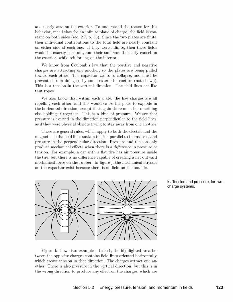
k / Tension and pressure, for two-charge systems.
Figure k shows two examples. In k/1, the highlighted area be-tween the opposite charges contains field lines oriented horizontally,which create tension in that direction. The charges attract one an-other. There is also pressure in the vertical direction, but this is inthe wrong direction to produce any effect on the charges, which are
Section 5.2 Energy, pressure, tension, and momentum in fields 123

l / Tension in the electric fieldsurrounding a charged sphere.
m / Example 6. The appara-tus was about half a meter tall.
separated from each other horizontally.
In k/2, the highlighted area between the two positive chargescontains field lines that exhibit vertical pressure, causing a repulsionbetween the charges, along with a horizontal tension which has noeffect on them.
In both examples in figure k, we have highlighted an area be-tween the charges, but it also matters that there is a differencebetween the pressure or tension in this area and that on the out-side.
To see the advantage of this mode of reasoning, compare with themuch more complicated logic that we had to do on p. 42 in order toanalyze the situation k/1 by talking about the change in the fields’energy that would have occurred if they were moved closer togetheror farther apart. (Cf. also the complicated handling of the limits ofintegration in note 64.)
Figure l shows the example of a charged, conducting sphere.The charge distributes itself uniformly on the surface, and the fieldis zero on the inside. The surface of the sphere wants to explodebecause of the electrical repulsion. We confirm this because there istension on the outside of the sphere, but none on the inside. Thisimbalance causes any piece of the surface to feel a net outward force.
Magnetostriction example 6The examples discussed above involved pressure and tensionmade by electric fields, but an exactly analogous effect occurs formagnetism. If you’ve ever heard a transformer buzzing, you’veobserved it.
Figure m shows part of a sensitive experiment carried out byJames Joule in 1842 which discovered the effect. Joule writes,“About the close of the year 1841, Mr. F.D. Arstall, an ingeniousmachinist of this town, suggested to me a new form of electro-magnetic engine. He was of the opinion that a bar of iron expe-rienced an increase of bulk by receiving the magnetic condition.”Joule first constructed a delicate experiment to look for a changein the length of an iron bar when it was used as the core of asolenoid. In an iron bar about half a meter tall, he found a de-crease in length of a little more than one part per million, with thestrongest field he could make. This is called magnetostriction.
This would suggest a decrease in volume as well, but there wasno sufficiently accurate way to measure the small diameter of thebar. Therefore Joule created the apparatus in figure m, in whichthe bar was submerged in water, with a thin capillary tube at thetop to take the volume of any small displacement of water andamplify it into a visible change in height. The result was no de-tectable volume change.
124 Chapter 5 Electromagnetism
These results seem natural in view of our picture of fields ascarrying tension in the longitudinal direction and pressure in thetransverse direction. The interior field of the solenoid, as shownin figure g, runs in the vertical direction. The lengthwise tensionreduced the length of the bar, but the transverse pressure ex-panded its diameter, and the result was that the volume stayedthe same.
In the more familiar modern example of the buzzing transformer,an AC current at 60 Hz creates oscillations at a frequency of 120Hz. This doubling of the frequency occurs because the energy,pressure, and tension of a field all depend on the square of thefield, so that for a magnetic field, B produces the same effect as−B. This means that the maximum magnetostriction occurs twiceper cycle, at both the peak and the trough of the sine wave.
Section 5.2 Energy, pressure, tension, and momentum in fields 125

n / A mechanical example ofshear forces. If the plate of jellois disturbed horizontally, internalshear forces bring it back toequilibrium.
It is beyond the scope of this book to work out fully generalequations for the pressure and tension in the fields. In the mostgeneral case, when both an electric and a magnetic field are present,this gets a little complicated, and one needs to consider not justpressure and tension but also shear forces, figure n. However, whenonly one field is present, we can make a few simple observations.Let’s say this is an electric field. Symmetry prevents the existenceof any shear forces, so we can only have tension in the directionparallel to the field and pressure along the two axes perpendicularto it. Symmetry requires that the pressures along these two axes beequal. Furthermore, if the only quantities we have handy are k andE, then units require that the pressure and tension be proportionalE2 (problem 21, p. 145), as we would have expected, since rotationalinvariance requires that the pressure remain unchanged if we replaceE with −E. It also turns out that the pressures are equal to thetension in absolute value (138).
Summarizing, we find that when the field is purely electric orpurely magnetic:
• There are only pressure P and tension T , not shear, and bothare proportional to the square of the field.
• |P | = |T |
126 Chapter 5 Electromagnetism

o / A uniform magnetic fieldsuperposed on the field of a wirecarrying current into the page.
5.3 Force of a magnetic field on a charge
Figure o shows the superposition of two magnetic fields. One isa uniform field pointing to the left, and the other is the field of awire carrying a current that flows into the page. (The circle witha cross is a standard way of indicating a direction into the page,meant to evoke the tail feathers of an arrow. A circle with a dotwould mean a direction out of the page.) To construct this diagram,we only needed vector addition plus the facts about the magneticfield of a wire proved in example 2 on p. 117. Since that exampledid not include any derivation of the constant of proportionality inthe relationship B ∝ 1/r, we can’t say, in any particular set of units,what is the current in the wire that would produce exactly this fieldpattern.
Since the pressure is greater below the wire than above it, thereis an upward force on the wire. Summarizing the geometrical rela-tionship, we have:
current into the page
B to the left
force up.
This is a right-hand rule, which smells like a cross product. Sincethe cross product is the only rotationally invariant way to multiplytwo vectors in order to get a third vector, the only possible force lawconsistent with these observations is that when a charged particlemoves with velocity v through a magnetic field B, the force actingon the particle is proportional to qv ×B. The constant of propor-tionality has to be unitless, and although we haven’t yet proved it,this constant equals 1. Taking into account the possibility that theparticle is also acted on by an electric field, we have
F = qE + qv ×B,
which is known as the Lorentz force law.
As an application, we can now describe how Thomson was ableto measure the velocity of the electrons in the experiment in whichhe discovered the electron. As described in sec. 3.2, p. 76, he mea-sured the deflection of the electrons in an electric field, but he alsodetermined how much magnetic field, applied perpendicular to thebeam, was necessary in order to produce the same deflection. Hethen had v = E/B.
Thomson was using a beam of electrons in a vacuum tube, butin applications it is more common for the moving charges to be theones in a current-carrying wire. When the wire is perpendicular tothe field, as in figure o, the force per unit length acting on the wireis F/` = IB (problem 13, p. 142).
Section 5.3 Force of a magnetic field on a charge 127

p / A compass needle in theearth’s field.
5.4 The dipole
Figure p shows the superposition of a compass needle’s mag-netic field (essentially the field of figure m, p. 26) with the earth’smagnetic field. The compass is not aligned with the earth’s field,and from what we know about magnetic compasses we expect thatthere will now be a torque that will tend to bring it into alignment.It could in principle be very difficult to find this torque, since themagnetic field pattern is so complicated. But by using the visualtechniques of section 5.2.2, it’s pretty easy to get the right answerfor its sign. There is tension at the top right and bottom left of theneedle because of the densely packed field lines. This tension willcreate a counterclockwise torque.
A real-world hiking compass is usually filled with water in orderto create friction. The needle vibrates about an equilibrium, butthis friction rapidly kills the oscillations, and it ends up in a stateof lowest energy, in which it is aligned with the earth’s field (137).If we were to redraw figure p for the equilibrium condition, it wouldhave a left-right mirror symmetry, so the torque must vanish, andthis is consistent with equilibrium.
The reason we can treat the earth’s field as uniform in this ex-ample is that the compass is so small compared the earth. In thisapproximation, which is an excellent one in this example, we canthink of the compass as an idealized, very small object which feelsno net force from the field, only a torque.1 Such an idealized objectis called a dipole. There can be both electric and magnetic dipoles.An electric dipole tends to align itself with the electric field.
If we change the orientation of a dipole, say a magnetic one,then its own contribution to the field, B1 rotates along with it.Meanwhile, the external field B2 remains constant. For a givenorientation, the superposition of the two fields may be somethingcomplicated like figure p. But regardless of how complicated it is,the total energy of this field will always vary with orientation in avery simple way: it is proportional to the cosine of the angle betweenthe external field and an axis, such as the long axis of the compassneedle, determined by the structure of the dipole (proof 138). Thisis the behavior of a vector dot product, so we have for the energy
U = −m ·B,
where m is a vector called the dipole moment, and the minus signis a matter of convention.
A mechanical analogy is that if a pendulum has length ` andmass M at the end, then we can define a vector with magnitude `M
1To get a nonvanishing force from the earth’s magnetic field, we would haveto have an isolated “magnetic charge,” and the apparent nonexistence of suchthings is expressed by Gauss’s law for magnetism.
128 Chapter 5 Electromagnetism
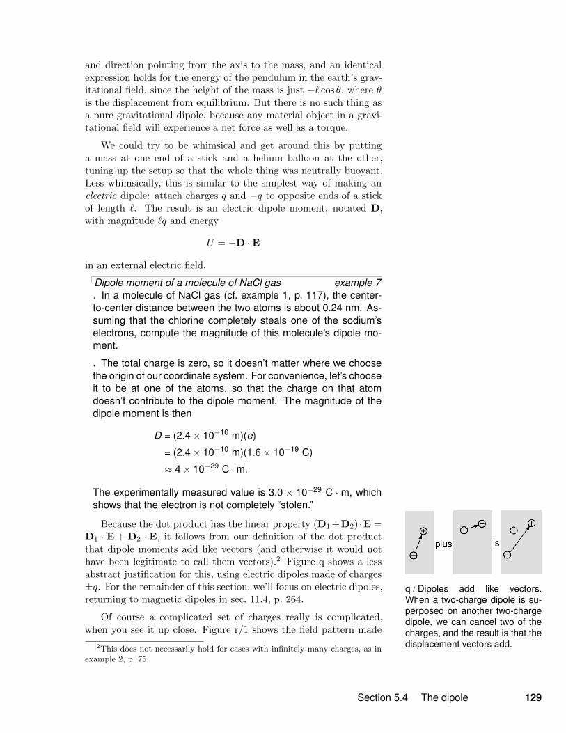
q / Dipoles add like vectors.When a two-charge dipole is su-perposed on another two-chargedipole, we can cancel two of thecharges, and the result is that thedisplacement vectors add.
and direction pointing from the axis to the mass, and an identicalexpression holds for the energy of the pendulum in the earth’s grav-itational field, since the height of the mass is just −` cos θ, where θis the displacement from equilibrium. But there is no such thing asa pure gravitational dipole, because any material object in a gravi-tational field will experience a net force as well as a torque.
We could try to be whimsical and get around this by puttinga mass at one end of a stick and a helium balloon at the other,tuning up the setup so that the whole thing was neutrally buoyant.Less whimsically, this is similar to the simplest way of making anelectric dipole: attach charges q and −q to opposite ends of a stickof length `. The result is an electric dipole moment, notated D,with magnitude `q and energy
U = −D ·E
in an external electric field.
Dipole moment of a molecule of NaCl gas example 7. In a molecule of NaCl gas (cf. example 1, p. 117), the center-to-center distance between the two atoms is about 0.24 nm. As-suming that the chlorine completely steals one of the sodium’selectrons, compute the magnitude of this molecule’s dipole mo-ment.
. The total charge is zero, so it doesn’t matter where we choosethe origin of our coordinate system. For convenience, let’s chooseit to be at one of the atoms, so that the charge on that atomdoesn’t contribute to the dipole moment. The magnitude of thedipole moment is then
D = (2.4× 10⁻¹⁰ m)(e)
= (2.4× 10⁻¹⁰ m)(1.6× 10⁻¹⁹ C)
≈ 4× 10⁻²⁹ C ·m.
The experimentally measured value is 3.0 × 10⁻²⁹ C · m, whichshows that the electron is not completely “stolen.”
Because the dot product has the linear property (D1 +D2) ·E =D1 · E + D2 · E, it follows from our definition of the dot productthat dipole moments add like vectors (and otherwise it would nothave been legitimate to call them vectors).2 Figure q shows a lessabstract justification for this, using electric dipoles made of charges±q. For the remainder of this section, we’ll focus on electric dipoles,returning to magnetic dipoles in sec. 11.4, p. 264.
Of course a complicated set of charges really is complicated,when you see it up close. Figure r/1 shows the field pattern made
2This does not necessarily hold for cases with infinitely many charges, as inexample 2, p. 75.
Section 5.4 The dipole 129
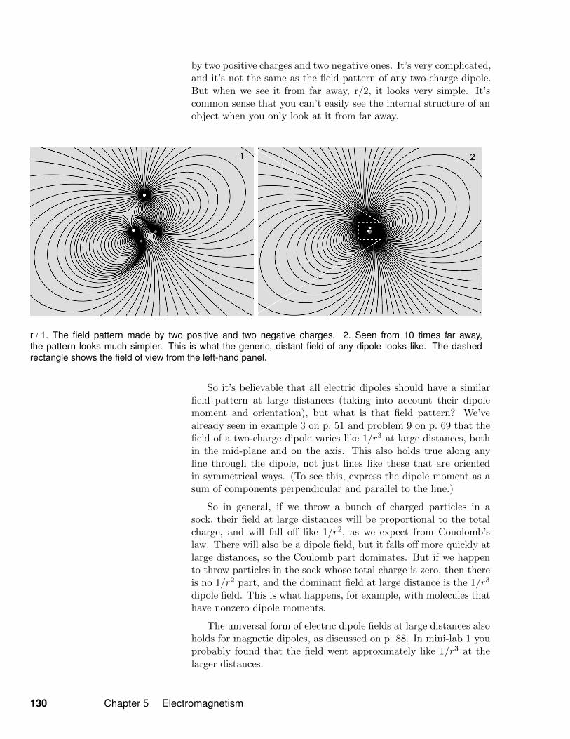
by two positive charges and two negative ones. It’s very complicated,and it’s not the same as the field pattern of any two-charge dipole.But when we see it from far away, r/2, it looks very simple. It’scommon sense that you can’t easily see the internal structure of anobject when you only look at it from far away.
r / 1. The field pattern made by two positive and two negative charges. 2. Seen from 10 times far away,the pattern looks much simpler. This is what the generic, distant field of any dipole looks like. The dashedrectangle shows the field of view from the left-hand panel.
So it’s believable that all electric dipoles should have a similarfield pattern at large distances (taking into account their dipolemoment and orientation), but what is that field pattern? We’vealready seen in example 3 on p. 51 and problem 9 on p. 69 that thefield of a two-charge dipole varies like 1/r3 at large distances, bothin the mid-plane and on the axis. This also holds true along anyline through the dipole, not just lines like these that are orientedin symmetrical ways. (To see this, express the dipole moment as asum of components perpendicular and parallel to the line.)
So in general, if we throw a bunch of charged particles in asock, their field at large distances will be proportional to the totalcharge, and will fall off like 1/r2, as we expect from Couolomb’slaw. There will also be a dipole field, but it falls off more quickly atlarge distances, so the Coulomb part dominates. But if we happento throw particles in the sock whose total charge is zero, then thereis no 1/r2 part, and the dominant field at large distance is the 1/r3
dipole field. This is what happens, for example, with molecules thathave nonzero dipole moments.
The universal form of electric dipole fields at large distances alsoholds for magnetic dipoles, as discussed on p. 88. In mini-lab 1 youprobably found that the field went approximately like 1/r3 at thelarger distances.
130 Chapter 5 Electromagnetism
t / 1. A charged piece of plasticpipe attracts an uncharged pieceof paper. 2. The mechanismfor the effect. 3. The analogousmagnetic effect.
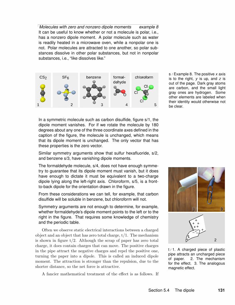
Molecules with zero and nonzero dipole moments example 8It can be useful to know whether or not a molecule is polar, i.e.,has a nonzero dipole moment. A polar molecule such as wateris readily heated in a microwave oven, while a nonpolar one isnot. Polar molecules are attracted to one another, so polar sub-stances dissolve in other polar substances, but not in nonpolarsubstances, i.e., “like dissolves like.”
s / Example 8. The positive x axisis to the right, y is up, and z isout of the page. Dark gray atomsare carbon, and the small lightgray ones are hydrogen. Someother elements are labeled whentheir identity would otherwise notbe clear.
In a symmetric molecule such as carbon disulfide, figure s/1, thedipole moment vanishes. For if we rotate the molecule by 180degrees about any one of the three coordinate axes defined in thecaption of the figure, the molecule is unchanged, which meansthat its dipole moment is unchanged. The only vector that hasthese properties is the zero vector.
Similar symmetry arguments show that sulfur hexafluoride, s/2,and benzene s/3, have vanishing dipole moments.
The formaldehyde molecule, s/4, does not have enough symme-try to guarantee that its dipole moment must vanish, but it doeshave enough to dictate it must be equivalent to a two-chargedipole lying along the left-right axis. Chloroform, s/5, is a front-to-back dipole for the orientation drawn in the figure.
From these considerations we can tell, for example, that carbondisulfide will be soluble in benzene, but chloroform will not.
Symmetry arguments are not enough to determine, for example,whether formaldehyde’s dipole moment points to the left or to theright in the figure. That requires some knowledge of chemistryand the periodic table.
Often we observe static electrical interactions between a chargedobject and an object that has zero total charge, t/1. The mechanismis shown in figure t/2. Although the scrap of paper has zero totalcharge, it does contain charges that can move. The positive chargesin the pipe attract the negative charges and repel the positive one,turning the paper into a dipole. This is called an induced dipolemoment. The attraction is stronger than the repulsion, due to theshorter distance, so the net force is attractive.
A fancier mathematical treatment of the effect is as follows. If
Section 5.4 The dipole 131
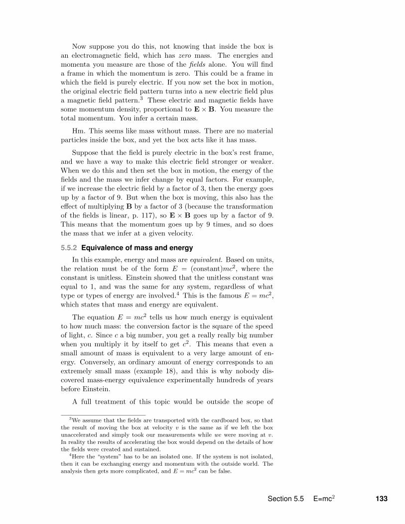
v / The black box has elec-tromagnetic fields inside. If weshake it, it has inertia.
a dipole with zero total charge is placed in a uniform field, it mayexperience a torque, but it will not experience any force. The situa-tion changes if the field is nonuniform. The force in the x directionis
Fx = −∂U∂x
.
We then have
Fx = − ∂
∂x(D ·E) = D · ∂E
∂x,
which depends on the dipole’s properties only through D. Similarexpressions apply for the y and z components.
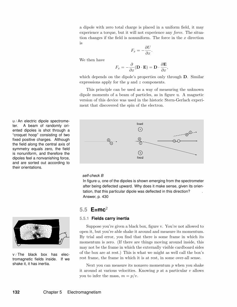
This principle can be used as a way of measuring the unknowndipole moments of a beam of particles, as in figure u. A magneticversion of this device was used in the historic Stern-Gerlach experi-ment that discovered the spin of the electron.
u / An electric dipole spectrome-ter. A beam of randomly ori-ented dipoles is shot through a“croquet hoop” consisting of twofixed positive charges. Althoughthe field along the central axis ofsymmetry equals zero, the fieldis nonuniform, and therefore thedipoles feel a nonvanishing force,and are sorted out according totheir orientations.
self-check BIn figure u, one of the dipoles is shown emerging from the spectrometerafter being deflected upward. Why does it make sense, given its orien-tation, that this particular dipole was deflected in this direction? .
Answer, p. 430
5.5 E=mc2
5.5.1 Fields carry inertia
Suppose you’re given a black box, figure v. You’re not allowed toopen it, but you’re able shake it around and measure its momentum.By trial and error, you find that there is some frame in which itsmomentum is zero. (If there are things moving around inside, thismay not be the frame in which the externally visible cardboard sidesof the box are at rest.) This is what we might as well call the box’srest frame, the frame in which it is at rest, in some over-all sense.
Next you can measure its nonzero momentum p when you shakeit around at various velocities. Knowing p at a particular v allowsyou to infer the mass, m = p/v.
132 Chapter 5 Electromagnetism
Now suppose you do this, not knowing that inside the box isan electromagnetic field, which has zero mass. The energies andmomenta you measure are those of the fields alone. You will finda frame in which the momentum is zero. This could be a frame inwhich the field is purely electric. If you now set the box in motion,the original electric field pattern turns into a new electric field plusa magnetic field pattern.3 These electric and magnetic fields havesome momentum density, proportional to E×B. You measure thetotal momentum. You infer a certain mass.
Hm. This seems like mass without mass. There are no materialparticles inside the box, and yet the box acts like it has mass.
Suppose that the field is purely electric in the box’s rest frame,and we have a way to make this electric field stronger or weaker.When we do this and then set the box in motion, the energy of thefields and the mass we infer change by equal factors. For example,if we increase the electric field by a factor of 3, then the energy goesup by a factor of 9. But when the box is moving, this also has theeffect of multiplying B by a factor of 3 (because the transformationof the fields is linear, p. 117), so E × B goes up by a factor of 9.This means that the momentum goes up by 9 times, and so doesthe mass that we infer at a given velocity.
5.5.2 Equivalence of mass and energy
In this example, energy and mass are equivalent. Based on units,the relation must be of the form E = (constant)mc2, where theconstant is unitless. Einstein showed that the unitless constant wasequal to 1, and was the same for any system, regardless of whattype or types of energy are involved.4 This is the famous E = mc2,which states that mass and energy are equivalent.
The equation E = mc2 tells us how much energy is equivalentto how much mass: the conversion factor is the square of the speedof light, c. Since c a big number, you get a really really big numberwhen you multiply it by itself to get c2. This means that even asmall amount of mass is equivalent to a very large amount of en-ergy. Conversely, an ordinary amount of energy corresponds to anextremely small mass (example 18), and this is why nobody dis-covered mass-energy equivalence experimentally hundreds of yearsbefore Einstein.
A full treatment of this topic would be outside the scope of
3We assume that the fields are transported with the cardboard box, so thatthe result of moving the box at velocity v is the same as if we left the boxunaccelerated and simply took our measurements while we were moving at v.In reality the results of accelerating the box would depend on the details of howthe fields were created and sustained.
4Here the “system” has to be an isolated one. If the system is not isolated,then it can be exchanging energy and momentum with the outside world. Theanalysis then gets more complicated, and E = mc2 can be false.
Section 5.5 E=mc2 133

w / Top: A PET scanner. Middle:Each positron annihilates with anelectron, producing two gamma-rays that fly off back-to-back.When two gamma rays are ob-served simultaneously in the ringof detectors, they are assumed tocome from the same annihilationevent, and the point at which theywere emitted must lie on the lineconnecting the two detectors.Bottom: A scan of a person’storso. The body has concentratedthe radioactive tracer around thestomach, indicating an abnormalmedical condition.
this book, but it’s fairly easy to see that if mass is equivalent toone form of energy, then it must be equivalent to all other formsof energy, with the same conversion factor. Let’s take heat as anexample. Suppose a rocket ship contains some electrical energystored in a battery. What if we believed that E = mc2 applied toelectromagnetic energy but not to heat. Then the pilot of the rocketcould use a battery to run a heater, decreasing the mass of the ship.Since momentum p = mv is conserved, this would require that theship speed up!
This would not only be strange, but it would violate the principlethat motion is relative, because the result of the experiment wouldbe different depending on whether the ship was at rest or not. Theonly logical conclusion is that all forms of energy are equivalent tomass. Running the heater then has no effect on the motion of theship, because the total energy in the ship was unchanged; one formof energy (electrical) was simply converted to another (heat).
A somewhat different, and equally valid, way of looking at E =mc2 is that energy and mass are not separately conserved. Thereforewe can have processes that convert one to the other.
A rusting nail example 9. An iron nail is left in a cup of water until it turns entirely to rust.The energy released is about 0.5 MJ. In theory, would a suffi-ciently precise scale register a change in mass? If so, how much?
. The energy will appear as heat, which will be lost to the envi-ronment. The total mass-energy of the cup, water, and iron willindeed be lessened by 0.5 MJ. (If it had been perfectly insulated,there would have been no change, since the heat energy wouldhave been trapped in the cup.) The speed of light is c = 3 × 10⁸
meters per second, so converting to mass units, we have
m =Ec2
=0.5× 10⁶ J(
3× 10⁸ m/s)2
= 6× 10⁻¹² kilograms.
The change in mass is too small to measure with any practicaltechnique. This is because the square of the speed of light issuch a large number.
Electron-positron annihilation example 10Natural radioactivity in the earth produces positrons, which are
like electrons but have the opposite charge. A form of antimat-ter, positrons annihilate with electrons to produce gamma rays, aform of high-frequency light. Such a process would have beenconsidered impossible before Einstein, because conservation ofmass and energy were believed to be separate principles, and
134 Chapter 5 Electromagnetism

this process eliminates 100% of the original mass. The amountof energy produced by annihilating 1 kg of matter with 1 kg ofantimatter is
E = mc2
= (2 kg)(
3.0× 10⁸ m/s)2
= 2× 10¹⁷ J,
which is on the same order of magnitude as a day’s energy con-sumption for the entire world’s population!
Positron annihilation forms the basis for the medical imaging tech-nique called a PET (positron emission tomography) scan, in whicha positron-emitting chemical is injected into the patient and map-ped by the emission of gamma rays from the parts of the bodywhere it accumulates.
5.5.3 A naughty infinity
In this subsection we discuss a theoretical issue that ends uphaving far-reaching implications. The reader who doesn’t find thisside-trip interesting can skip it.
Your mental picture of an electron may be either a point or asmall sphere. Which is right? Suppose that we think of it as asphere of finite radius r, containing a uniformly distributed chargeq. Its electric field contains some amount of energy E, and it followsfrom units that this energy equals kq2/r, multiplied by some unitlessconstant. The unitless constant is calculated in problem 9, p. 250,but all that matters for our present purposes is that it’s positive,since the energy density is everywhere positive, and the integral ofsomething positive must be positive.
Now clearly bad things will happen if we set r = 0. The energyof the electric field will blow up to infinity. Before Einstein, wecould have said that this was not necessarily a cosmic catastrophe.A physicist of the 19th century would probably have sniggered andtold us patronizingly that the energy E would be of no consequencein any case, because almost all of it was locked up in the part of thefield very close to the electron, and was therefore basically a constantand fixed contribution to the total energy of the universe. Addingany constant, no matter how large, to the total energy of the universehas no observable consequences. Worrying about whether r is trulyexactly zero, our supercilious friend tells us, is something that cannever be tested experimentally, and is therefore a meaningless thingto discuss, like how many angels can dance on the head of a pin.
But Einstein’s E = mc2 tells us that the issue cannot be wavedaway so easily. The field’s energy is equivalent to a certain amountof mass. It should contribute to the electron’s inertia. Now we knowwhat the mass is, so the energy in the field must be . mc2. This
Section 5.5 E=mc2 135

results in r & r0 = ke2/mc2, where r0 is called the classical electronradius, although it doesn’t just apply to electrons. Furthermore,there are processes that create electron-antielectron pairs, and theseprocesses don’t require infinite energy. The energy required to createsuch a pair should only be 2mc2, which is finite. In general, classicalelectromagnetism becomes an inconsistent theory if you considerpoint particles with r . r0.
Thus relativity seems to suggest that charged particles can’t bepointlike, and that there should be a lower bound on their sizes.For an electron, r0 is on the order of 10−15 meters. Particle physicsexperiments became good enough decades ago to search for internalstructure in the electron at this scale, and they tell us that it doesn’texist, in the sense that the electron cannot be a composite particle atthis scale. (For comparison, they tell us that a proton is composite— it turns out to be made of quarks.)
One could imagine that the electron had a finite size without be-ing composed of smaller particles, which would be consistent withthe particle physics experiments, because they basically test whetherthings can be broken up or internally manipulated, like taking a me-chanical pocketwatch and hitting it with a hammer. Maybe thereis size without any dynamical internal structure, just a rigid chargedistribution. Physicists around 1900 did put great effort into con-structing such models of the electron, but they never succeeded.With hindsight, we can see that this approach, too, was doomed be-cause of relativity. Relativity doesn’t allow perfectly rigid objects.In such an object, vibrations would propagate as sound waves atinfinite speed, but relativity doesn’t allow speeds greater than c.
So in the end, if we want to describe the charge and electricfield of an electron at scales below r0, we need some other theoryof nature than classical electricity and magnetism. That theory isquantum mechanics. In nonrigorous language, quantum mechanicsdescribes the scene at this scale in terms of rapid, random quantumfluctuations, with particle-antiparticle pairs springing into existenceand then reannihilating.
5.5.4 Summary of relativity
Summarizing what we know so far about relativity, we have thefollowing:
• Time is relative. The rate at which a clock runs is greatest inthe frame where the clock is at rest.
• For consistency with item 1, nothing can go faster than c.
• Mass and energy are equivalent, E = mc2.
136 Chapter 5 Electromagnetism
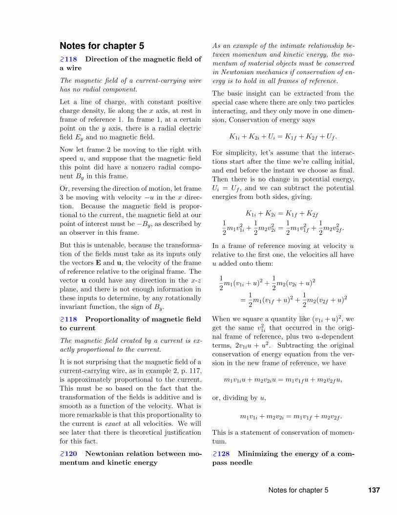
Notes for chapter 5118 Direction of the magnetic field ofa wire
The magnetic field of a current-carrying wirehas no radial component.
Let a line of charge, with constant positivecharge density, lie along the x axis, at rest inframe of reference 1. In frame 1, at a certainpoint on the y axis, there is a radial electricfield Ey and no magnetic field.
Now let frame 2 be moving to the right withspeed u, and suppose that the magnetic fieldthis point did have a nonzero radial compo-nent By in this frame.
Or, reversing the direction of motion, let frame3 be moving with velocity −u in the x direc-tion. Because the magnetic field is propor-tional to the current, the magnetic field at ourpoint of interest must be −By, as described byan observer in this frame.
But this is untenable, because the transforma-tion of the fields must take as its inputs onlythe vectors E and u, the velocity of the frameof reference relative to the original frame. Thevector u could have any direction in the x-zplane, and there is not enough information inthese inputs to determine, by any rotationallyinvariant function, the sign of By.
118 Proportionality of magnetic fieldto current
The magnetic field created by a current is ex-actly proportional to the current.
It is not surprising that the magnetic field of acurrent-carrying wire, as in example 2, p. 117,is approximately proportional to the current.This must be so based on the fact that thetransformation of the fields is additive and issmooth as a function of the velocity. What ismore remarkable is that this proportionality tothe current is exact at all velocities. We willsee later that there is theoretical justificationfor this fact.
120 Newtonian relation between mo-mentum and kinetic energy
As an example of the intimate relationship be-tween momentum and kinetic energy, the mo-mentum of material objects must be conservedin Newtonian mechanics if conservation of en-ergy is to hold in all frames of reference.
The basic insight can be extracted from thespecial case where there are only two particlesinteracting, and they only move in one dimen-sion, Conservation of energy says
K1i +K2i + Ui = K1f +K2f + Uf .
For simplicity, let’s assume that the interac-tions start after the time we’re calling initial,and end before the instant we choose as final.Then there is no change in potential energy,Ui = Uf , and we can subtract the potentialenergies from both sides, giving.
K1i +K2i = K1f +K2f
1
2m1v
21i +
1
2m2v
22i =
1
2m1v
21f +
1
2m2v
22f .
In a frame of reference moving at velocity urelative to the first one, the velocities all haveu added onto them:
1
2m1(v1i + u)2 +
1
2m2(v2i + u)2
=1
2m1(v1f + u)2 +
1
2m2(v2f + u)2
When we square a quantity like (v1i + u)2, weget the same v2
1i that occurred in the origi-nal frame of reference, plus two u-dependentterms, 2v1iu + u2. Subtracting the originalconservation of energy equation from the ver-sion in the new frame of reference, we have
m1v1iu+m2v2iu = m1v1fu+m2v2fu,
or, dividing by u,
m1v1i +m2v2i = m1v1f +m2v2f .
This is a statement of conservation of momen-tum.
128 Minimizing the energy of a com-pass needle
Notes for chapter 5 137

We discuss the minimization of the energy inthe magnetic field of a compass needle.
The result of our analysis of figure p on p. 128tells us that the compass needle will tend toalign itself so that its own internal field is inthe same direction as the ambient field. Thisis a little surprising, since the energy stored inthe magnetic field on the interior is then in-creased. However, the needle also contributesto the field outside itself, and this field ispredominantly in the opposite direction com-pared to the interior field. It’s true but notobvious that this smaller exterior field, inte-grated over the large exterior volume, ends upbeing the dominant effect.
128 Dipole’s energy proportional tocosine of an angle
We prove that the energy of a dipole in an ex-ternal field is proportional to the cosine of theangle between the field and some internal axisdetermined by the structure of the dipole.
In the notation introduced in the main text,B1 is the field of the dipole, B2 the uniformexternal field. The energy density of the to-tal magnetic field at any given point is pro-portional to (B1 + B2) · (B1 + B2), with theonly variation occurring because the wholefield pattern represented by B1 can be rigidlyrotated. Multiplying out the factors of thedot product, and discarding constant terms,we have 2B1 ·B2. The variable part of the to-tal energy is found by integrating this expres-sion over all space, but B2 is a constant, so wecan take it outside the integral, the result be-ing B2
∫. . . dv, where . . . represents whatever
field is going on inside the dipole. This has theform of a vector dot product, which is propor-tional to the cosine of the angle between thetwo factors.
126 In a pure electric field, |P | = |T |
We prove that in a pure electric field, the pres-sure and tension at a given point are equalin absolute value. Although we won’t prove ithere, the same holds for the magnetic field.
In the case of a purely electric field, we expect
the pressure and tension to depend only on thesquare of the field. Therefore, we only needone concrete example in which we know theanswer in order to show that the two constantsof proportionality are equal.
Physically, the simplest example of this typewould be the interaction between two pointcharges. However, the math turns out a littlesimpler if we instead consider two parallel linesof charge.
First consider the attractive case, with the twolines of charge having opposite densities λ and−λ of charge per unit length. These are paral-lel to the y axis and located at equal distancesabove and below the x-y plane, at z = ±h.Their attraction per unit length is propor-tional to the integral of the tension over theplane that is equidistant from the two lines.Each one contributes a field proportional to1/r, and the vector sum of the two fields isperpendicular to the plane and has a magni-tude proportional to r−1 cos θ, where θ is theangle between the the z axis and the radial lineto the point being considered. Since the ten-sion is proportional to the square of the field,the attractive force per unit length is propor-tional to the integral
∫∞−∞
(r−1 cos θ
)2dx. Do-
ing a change of variable to a unitless u = x/h,and expressing r, θ, and x in terms of u, weend up with the definite integral∫ ∞
−∞
du
(1 + u2)2=π
2.
Now we consider two lines of charge λ and λ,with the same sign, so that they repel one an-other. The combined field is now proportionalto r−1 sin θ. Discarding all the same constantfactors in the same way, but preserving thefactors that actually depend on u, we get theintegral ∫ ∞
−∞
u2 du
(1 + u2)2=π
2.
The forces are supposed to be equal, and thetwo definite integrals are equal. We thereforefind we have equal constants of proportionalityin the relation for the pressure and tension interms of the field.
138 Chapter 5 Electromagnetism
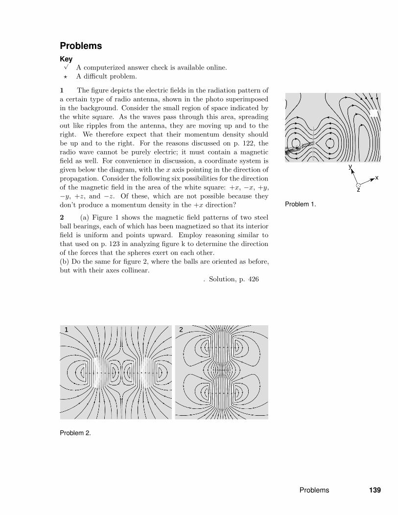
Problem 1.
ProblemsKey√
A computerized answer check is available online.? A difficult problem.
1 The figure depicts the electric fields in the radiation pattern ofa certain type of radio antenna, shown in the photo superimposedin the background. Consider the small region of space indicated bythe white square. As the waves pass through this area, spreadingout like ripples from the antenna, they are moving up and to theright. We therefore expect that their momentum density shouldbe up and to the right. For the reasons discussed on p. 122, theradio wave cannot be purely electric; it must contain a magneticfield as well. For convenience in discussion, a coordinate system isgiven below the diagram, with the x axis pointing in the direction ofpropagation. Consider the following six possibilities for the directionof the magnetic field in the area of the white square: +x, −x, +y,−y, +z, and −z. Of these, which are not possible because theydon’t produce a momentum density in the +x direction?
2 (a) Figure 1 shows the magnetic field patterns of two steelball bearings, each of which has been magnetized so that its interiorfield is uniform and points upward. Employ reasoning similar tothat used on p. 123 in analyzing figure k to determine the directionof the forces that the spheres exert on each other.(b) Do the same for figure 2, where the balls are oriented as before,but with their axes collinear.
. Solution, p. 426
Problem 2.
Problems 139
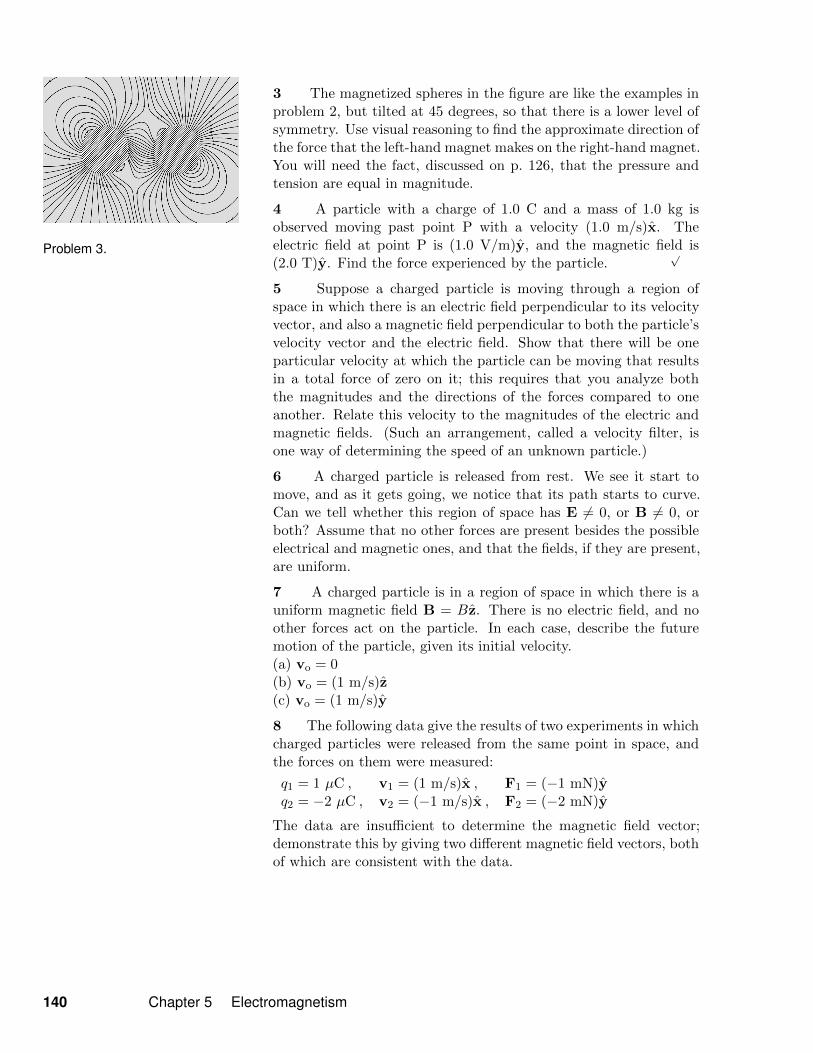
Problem 3.
3 The magnetized spheres in the figure are like the examples inproblem 2, but tilted at 45 degrees, so that there is a lower level ofsymmetry. Use visual reasoning to find the approximate direction ofthe force that the left-hand magnet makes on the right-hand magnet.You will need the fact, discussed on p. 126, that the pressure andtension are equal in magnitude.
4 A particle with a charge of 1.0 C and a mass of 1.0 kg isobserved moving past point P with a velocity (1.0 m/s)x. Theelectric field at point P is (1.0 V/m)y, and the magnetic field is(2.0 T)y. Find the force experienced by the particle.
√
5 Suppose a charged particle is moving through a region ofspace in which there is an electric field perpendicular to its velocityvector, and also a magnetic field perpendicular to both the particle’svelocity vector and the electric field. Show that there will be oneparticular velocity at which the particle can be moving that resultsin a total force of zero on it; this requires that you analyze boththe magnitudes and the directions of the forces compared to oneanother. Relate this velocity to the magnitudes of the electric andmagnetic fields. (Such an arrangement, called a velocity filter, isone way of determining the speed of an unknown particle.)
6 A charged particle is released from rest. We see it start tomove, and as it gets going, we notice that its path starts to curve.Can we tell whether this region of space has E 6= 0, or B 6= 0, orboth? Assume that no other forces are present besides the possibleelectrical and magnetic ones, and that the fields, if they are present,are uniform.
7 A charged particle is in a region of space in which there is auniform magnetic field B = Bz. There is no electric field, and noother forces act on the particle. In each case, describe the futuremotion of the particle, given its initial velocity.(a) vo = 0(b) vo = (1 m/s)z(c) vo = (1 m/s)y
8 The following data give the results of two experiments in whichcharged particles were released from the same point in space, andthe forces on them were measured:
q1 = 1 µC , v1 = (1 m/s)x , F1 = (−1 mN)yq2 = −2 µC , v2 = (−1 m/s)x , F2 = (−2 mN)y
The data are insufficient to determine the magnetic field vector;demonstrate this by giving two different magnetic field vectors, bothof which are consistent with the data.
140 Chapter 5 Electromagnetism

9 The following data give the results of two experiments in whichcharged particles were released from the same point in space, andthe forces on them were measured:
q1 = 1 nC , v1 = (1 m/s)z , F1 = (5 pN)x + (2 pN)yq2 = 1 nC , v2 = (3 m/s)z , F2 = (10 pN)x + (4 pN)y
Is there a nonzero electric field at this point? A nonzero magneticfield?
10 The following data give the results of three experiments inwhich charged particles were released from the same point in space,and the forces on them were measured:
q1 = 1 C , v1 = 0 , F1 = (1 N)yq2 = 1 C , v2 = (1 m/s)x , F2 = (1 N)yq3 = 1 C , v3 = (1 m/s)z , F3 = 0
Determine the electric and magnetic fields.√
11 In problem 10, the three experiments gave enough informationto determine both fields. Is it possible to design a procedure so that,using only two such experiments, we can always find E and B? Ifso, design it. If not, why not?
12 A charged particle of mass m and charge q moves in a circledue to a uniform magnetic field of magnitude B, which points per-pendicular to the plane of the circle.(a) Assume the particle is positively charged. Make a sketch show-ing the direction of motion and the direction of the field, and showthat the resulting force is in the right direction to produce circularmotion.(b) Find the radius, r, of the circle, in terms of m, q, v, and B.
√
(c) Show that your result from part b has the right units.(d) Discuss all four variables occurring on the right-hand side of youranswer from part b. Do they make sense? For instance, what shouldhappen to the radius when the magnetic field is made stronger?Does your equation behave this way?(e) Restate your result so that it gives the particle’s angular fre-quency, ω, in terms of the other variables, and show that v dropsout.
√
Remark: A charged particle can be accelerated in a circular device called acyclotron, in which a magnetic field is what keeps them from going off straight.This frequency is therefore known as the cyclotron frequency. The particles areaccelerated by other forces (electric forces), which are AC. As long as the electricfield is operated at the correct cyclotron frequency for the type of particles beingmanipulated, it will stay in sync with the particles, giving them a shove in theright direction each time they pass by. The particles are speeding up, so thisonly works because the cyclotron frequency is independent of velocity.
Problems 141
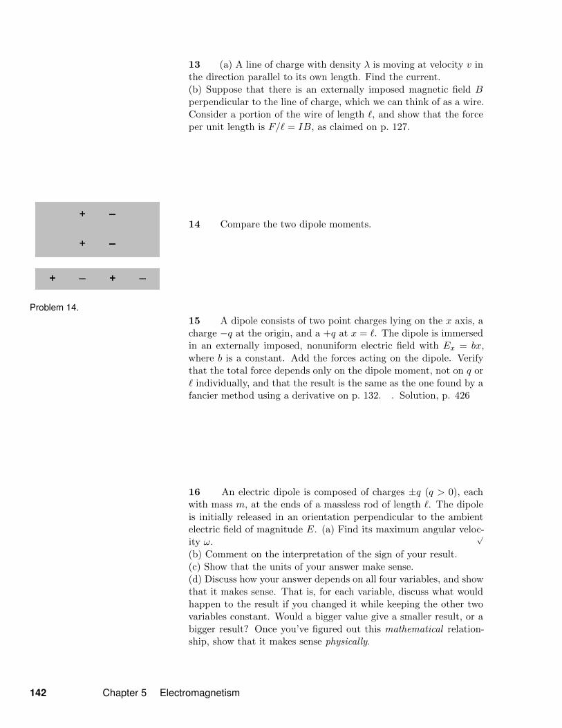
Problem 14.
13 (a) A line of charge with density λ is moving at velocity v inthe direction parallel to its own length. Find the current.(b) Suppose that there is an externally imposed magnetic field Bperpendicular to the line of charge, which we can think of as a wire.Consider a portion of the wire of length `, and show that the forceper unit length is F/` = IB, as claimed on p. 127.
14 Compare the two dipole moments.
15 A dipole consists of two point charges lying on the x axis, acharge −q at the origin, and a +q at x = `. The dipole is immersedin an externally imposed, nonuniform electric field with Ex = bx,where b is a constant. Add the forces acting on the dipole. Verifythat the total force depends only on the dipole moment, not on q or` individually, and that the result is the same as the one found by afancier method using a derivative on p. 132. . Solution, p. 426
16 An electric dipole is composed of charges ±q (q > 0), eachwith mass m, at the ends of a massless rod of length `. The dipoleis initially released in an orientation perpendicular to the ambientelectric field of magnitude E. (a) Find its maximum angular veloc-ity ω.
√
(b) Comment on the interpretation of the sign of your result.(c) Show that the units of your answer make sense.(d) Discuss how your answer depends on all four variables, and showthat it makes sense. That is, for each variable, discuss what wouldhappen to the result if you changed it while keeping the other twovariables constant. Would a bigger value give a smaller result, or abigger result? Once you’ve figured out this mathematical relation-ship, show that it makes sense physically.
142 Chapter 5 Electromagnetism

17 An electron has a nonzero magnetic dipole moment, which isaligned with its spin. Suppose that at distance r, at a certain pointin space relative to an electron, the magnetic field has magnitudeB. Find the magnitude of the magnetic field at a point lying atdistance 10r, along the same line.
√
18 The figure shows three molecules. You don’t actually need toknow any chemistry to do this problem, but in case you’re interested,they’re PCl2−5 , H3O+, and PF5, respectively. If you look carefully atthe figure, you should be able to see that molecule 1 is a pyramid, 2 isnot planar, and in 3 there are three atoms in a line plus three atomsarranged to form an equilateral triangle in a perpendicular plane.Use symmetry arguments to determine which of these moleculeshave zero electric dipole moments.
Problem 18.
Problems 143
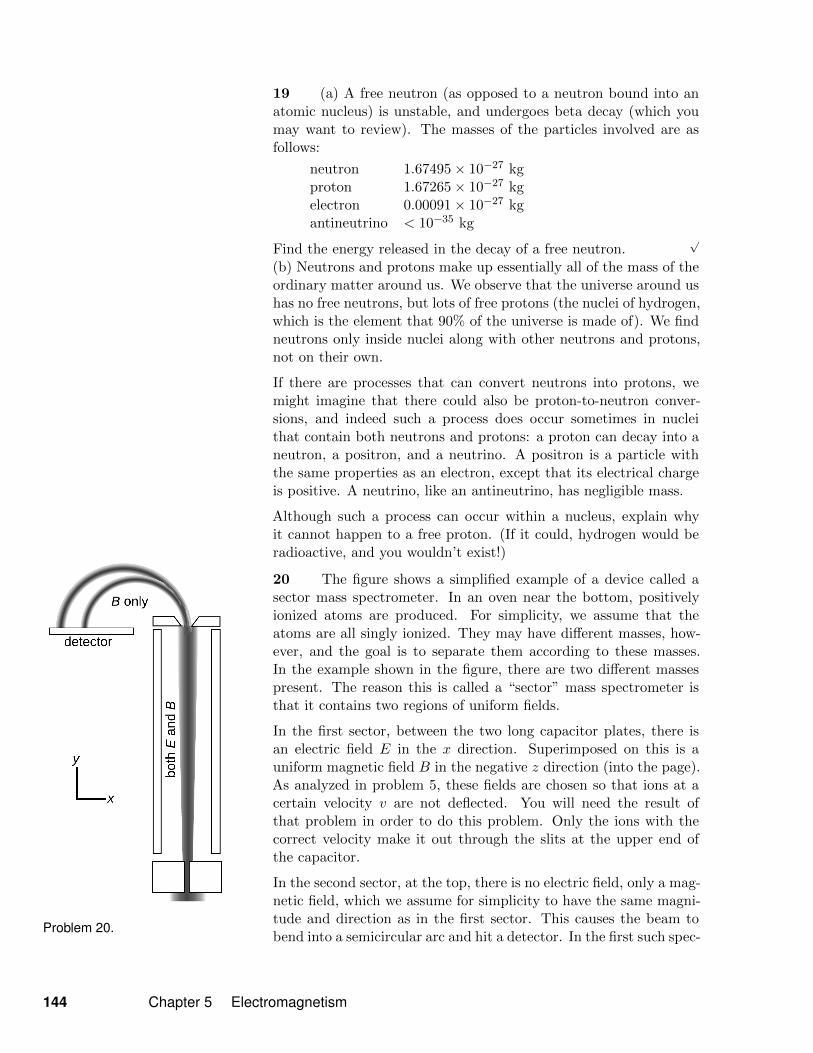
Problem 20.
19 (a) A free neutron (as opposed to a neutron bound into anatomic nucleus) is unstable, and undergoes beta decay (which youmay want to review). The masses of the particles involved are asfollows:
neutron 1.67495× 10⁻²⁷ kgproton 1.67265× 10⁻²⁷ kgelectron 0.00091× 10⁻²⁷ kgantineutrino < 10−35 kg
Find the energy released in the decay of a free neutron.√
(b) Neutrons and protons make up essentially all of the mass of theordinary matter around us. We observe that the universe around ushas no free neutrons, but lots of free protons (the nuclei of hydrogen,which is the element that 90% of the universe is made of). We findneutrons only inside nuclei along with other neutrons and protons,not on their own.
If there are processes that can convert neutrons into protons, wemight imagine that there could also be proton-to-neutron conver-sions, and indeed such a process does occur sometimes in nucleithat contain both neutrons and protons: a proton can decay into aneutron, a positron, and a neutrino. A positron is a particle withthe same properties as an electron, except that its electrical chargeis positive. A neutrino, like an antineutrino, has negligible mass.
Although such a process can occur within a nucleus, explain whyit cannot happen to a free proton. (If it could, hydrogen would beradioactive, and you wouldn’t exist!)
20 The figure shows a simplified example of a device called asector mass spectrometer. In an oven near the bottom, positivelyionized atoms are produced. For simplicity, we assume that theatoms are all singly ionized. They may have different masses, how-ever, and the goal is to separate them according to these masses.In the example shown in the figure, there are two different massespresent. The reason this is called a “sector” mass spectrometer isthat it contains two regions of uniform fields.
In the first sector, between the two long capacitor plates, there isan electric field E in the x direction. Superimposed on this is auniform magnetic field B in the negative z direction (into the page).As analyzed in problem 5, these fields are chosen so that ions at acertain velocity v are not deflected. You will need the result ofthat problem in order to do this problem. Only the ions with thecorrect velocity make it out through the slits at the upper end ofthe capacitor.
In the second sector, at the top, there is no electric field, only a mag-netic field, which we assume for simplicity to have the same magni-tude and direction as in the first sector. This causes the beam tobend into a semicircular arc and hit a detector. In the first such spec-
144 Chapter 5 Electromagnetism
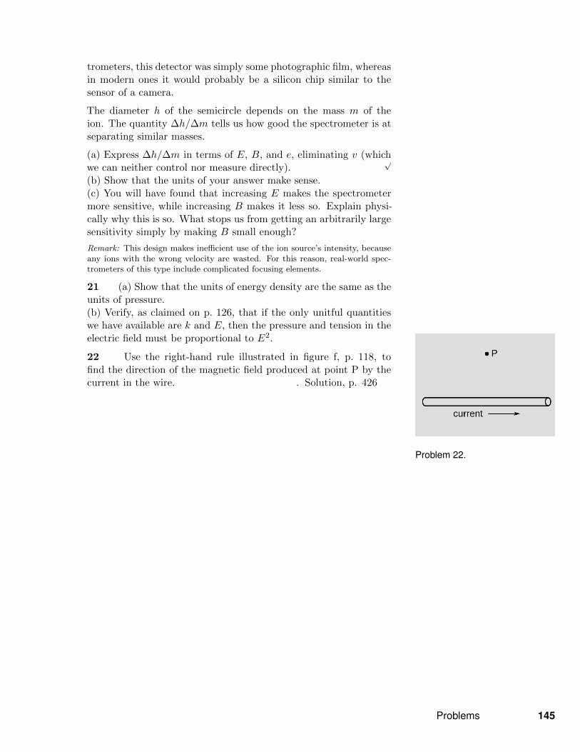
Problem 22.
trometers, this detector was simply some photographic film, whereasin modern ones it would probably be a silicon chip similar to thesensor of a camera.
The diameter h of the semicircle depends on the mass m of theion. The quantity ∆h/∆m tells us how good the spectrometer is atseparating similar masses.
(a) Express ∆h/∆m in terms of E, B, and e, eliminating v (whichwe can neither control nor measure directly).
√
(b) Show that the units of your answer make sense.(c) You will have found that increasing E makes the spectrometermore sensitive, while increasing B makes it less so. Explain physi-cally why this is so. What stops us from getting an arbitrarily largesensitivity simply by making B small enough?
Remark: This design makes inefficient use of the ion source’s intensity, becauseany ions with the wrong velocity are wasted. For this reason, real-world spec-trometers of this type include complicated focusing elements.
21 (a) Show that the units of energy density are the same as theunits of pressure.(b) Verify, as claimed on p. 126, that if the only unitful quantitieswe have available are k and E, then the pressure and tension in theelectric field must be proportional to E2.
22 Use the right-hand rule illustrated in figure f, p. 118, tofind the direction of the magnetic field produced at point P by thecurrent in the wire. . Solution, p. 426
Problems 145
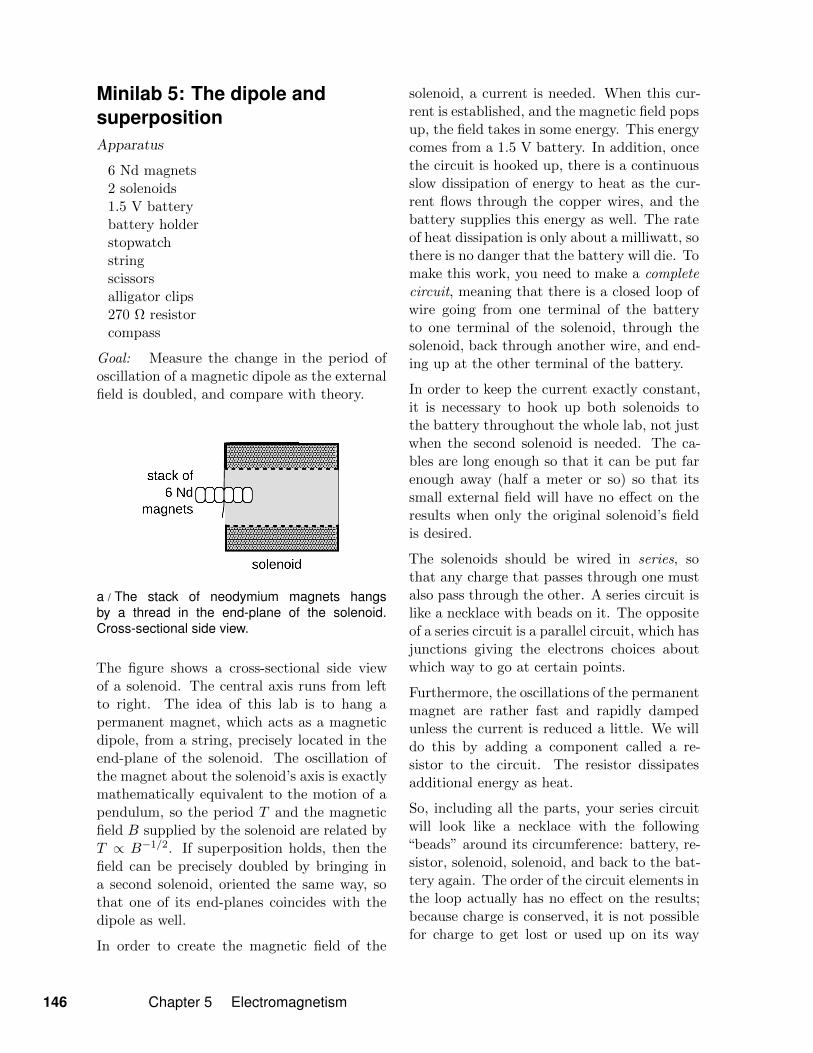
Minilab 5: The dipole andsuperpositionApparatus
6 Nd magnets2 solenoids1.5 V batterybattery holderstopwatchstringscissorsalligator clips270 Ω resistorcompass
Goal: Measure the change in the period ofoscillation of a magnetic dipole as the externalfield is doubled, and compare with theory.
a / The stack of neodymium magnets hangsby a thread in the end-plane of the solenoid.Cross-sectional side view.
The figure shows a cross-sectional side viewof a solenoid. The central axis runs from leftto right. The idea of this lab is to hang apermanent magnet, which acts as a magneticdipole, from a string, precisely located in theend-plane of the solenoid. The oscillation ofthe magnet about the solenoid’s axis is exactlymathematically equivalent to the motion of apendulum, so the period T and the magneticfield B supplied by the solenoid are related byT ∝ B−1/2. If superposition holds, then thefield can be precisely doubled by bringing ina second solenoid, oriented the same way, sothat one of its end-planes coincides with thedipole as well.
In order to create the magnetic field of the
solenoid, a current is needed. When this cur-rent is established, and the magnetic field popsup, the field takes in some energy. This energycomes from a 1.5 V battery. In addition, oncethe circuit is hooked up, there is a continuousslow dissipation of energy to heat as the cur-rent flows through the copper wires, and thebattery supplies this energy as well. The rateof heat dissipation is only about a milliwatt, sothere is no danger that the battery will die. Tomake this work, you need to make a completecircuit, meaning that there is a closed loop ofwire going from one terminal of the batteryto one terminal of the solenoid, through thesolenoid, back through another wire, and end-ing up at the other terminal of the battery.
In order to keep the current exactly constant,it is necessary to hook up both solenoids tothe battery throughout the whole lab, not justwhen the second solenoid is needed. The ca-bles are long enough so that it can be put farenough away (half a meter or so) so that itssmall external field will have no effect on theresults when only the original solenoid’s fieldis desired.
The solenoids should be wired in series, sothat any charge that passes through one mustalso pass through the other. A series circuit islike a necklace with beads on it. The oppositeof a series circuit is a parallel circuit, which hasjunctions giving the electrons choices aboutwhich way to go at certain points.
Furthermore, the oscillations of the permanentmagnet are rather fast and rapidly dampedunless the current is reduced a little. We willdo this by adding a component called a re-sistor to the circuit. The resistor dissipatesadditional energy as heat.
So, including all the parts, your series circuitwill look like a necklace with the following“beads” around its circumference: battery, re-sistor, solenoid, solenoid, and back to the bat-tery again. The order of the circuit elements inthe loop actually has no effect on the results;because charge is conserved, it is not possiblefor charge to get lost or used up on its way
146 Chapter 5 Electromagnetism

around the circuit.
A complication comes from the ambient fieldin the room, which is a combination of theearth’s field and the field of the building ma-terials. This field is a fraction of that of thesolenoids, but still significant enough to affectthe results. To deal with this, we will inten-tionally align the solenoids with the horizon-tal component of the ambient field, so thatthe vector addition of the horizontal fields isequivalent to addition of real numbers. Thenwe will take data with the current flowing inboth directions, so that in one case the am-bient field adds to the field of the solenoid(s)and in the other it subtracts. Averaging theperiods in these two conditions eliminates theeffect of the ambient field.
Minilab 5: The dipole and superposition 147

Exercise 5: Tension in the electric field1. Warm-up: Compare the charge on the terrier to the charges on the viola and the shoe.
2. Suppose that a metal plate is immersed in a uniform external electric field Eext. This fieldsuperposes with any field due to charge q on the plate itself. The force acting on the plate willdepend on the product qEext.
For the following examples, compare the forces, including both their direction and a quantitativemeasure of their strength.
3. Can you find a way to express these results in a simpler form, or make a rule that explainsthe results?
148 Chapter 5 Electromagnetism

a / “Why?”
Chapter 6
Radiation
Way back at the beginning of this book, on the second page of thevery first chapter, we proved, based only on experiments demon-strating the relative nature of time, that the universe could notoperate as envisioned in Newton’s picture of instantaneous actionat a distance. Electromagnetic forces must propagate as wave dis-turbances in the fields. Later we saw that the only sensible1 way offinding the direction of propagation of such a wave was the vectorcross product E×B, and argued (p. 122) that therefore these wavedisturbances must contain oscillations of both the electric and mag-netic field. In this chapter we will take up the description of theseelectromagnetic waves in more detail.
By the way, although I’m offering answers to “why” questionsabout these waves, it’s important to understand that in mathemat-ics and the hard sciences, a “why” question can have more than oneanswer. It’s different in other fields such as religion. If you ask atheologically well-informed Christian why humans have to endure
1i.e., rotationally invariant
149
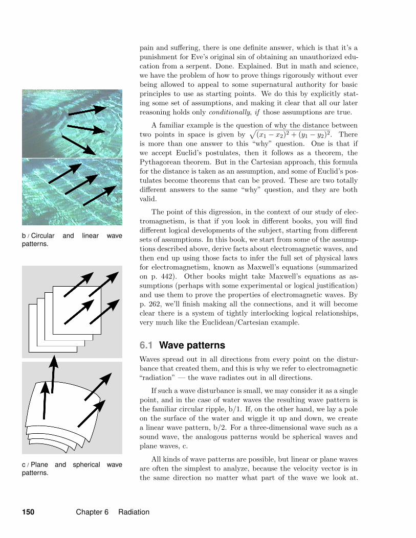
b / Circular and linear wavepatterns.
c / Plane and spherical wavepatterns.
pain and suffering, there is one definite answer, which is that it’s apunishment for Eve’s original sin of obtaining an unauthorized edu-cation from a serpent. Done. Explained. But in math and science,we have the problem of how to prove things rigorously without everbeing allowed to appeal to some supernatural authority for basicprinciples to use as starting points. We do this by explicitly stat-ing some set of assumptions, and making it clear that all our laterreasoning holds only conditionally, if those assumptions are true.
A familiar example is the question of why the distance betweentwo points in space is given by
√(x1 − x2)2 + (y1 − y2)2. There
is more than one answer to this “why” question. One is that ifwe accept Euclid’s postulates, then it follows as a theorem, thePythagorean theorem. But in the Cartesian approach, this formulafor the distance is taken as an assumption, and some of Euclid’s pos-tulates become theorems that can be proved. These are two totallydifferent answers to the same “why” question, and they are bothvalid.
The point of this digression, in the context of our study of elec-tromagnetism, is that if you look in different books, you will finddifferent logical developments of the subject, starting from differentsets of assumptions. In this book, we start from some of the assump-tions described above, derive facts about electromagnetic waves, andthen end up using those facts to infer the full set of physical lawsfor electromagnetism, known as Maxwell’s equations (summarizedon p. 442). Other books might take Maxwell’s equations as as-sumptions (perhaps with some experimental or logical justification)and use them to prove the properties of electromagnetic waves. Byp. 262, we’ll finish making all the connections, and it will becomeclear there is a system of tightly interlocking logical relationships,very much like the Euclidean/Cartesian example.
6.1 Wave patternsWaves spread out in all directions from every point on the distur-bance that created them, and this is why we refer to electromagnetic“radiation” — the wave radiates out in all directions.
If such a wave disturbance is small, we may consider it as a singlepoint, and in the case of water waves the resulting wave pattern isthe familiar circular ripple, b/1. If, on the other hand, we lay a poleon the surface of the water and wiggle it up and down, we createa linear wave pattern, b/2. For a three-dimensional wave such as asound wave, the analogous patterns would be spherical waves andplane waves, c.
All kinds of wave patterns are possible, but linear or plane wavesare often the simplest to analyze, because the velocity vector is inthe same direction no matter what part of the wave we look at.
150 Chapter 6 Radiation