NOTE: DOD-STD-2185 has been redesignated as a Standard...
29
NOTE: DOD-STD-2185 has been redesignated as a Standard Practice. The cover page has been changed for Administrative reasons. There are no other changes to this Document. DOD-STD-2185(SH) 28 OCTOBER 1986 SUPERSEDING NAVSEA 0991-LP-023-3002 15 July 1982 (See 6.4) AMSC N/A FSC 2010 DISTRIBUTION STATEMENT A. Approved for public release; distribution is unlimited. DEPARTMENT OF DEFENSE STANDARD PRACTICE REQUIREMENTS FOR REPAIR AND STRAIGHTENING OF BRONZE NAVAL SHIP PROPELLERS Downloaded from http://www.everyspec.com
Transcript of NOTE: DOD-STD-2185 has been redesignated as a Standard...

NOTE: DOD-STD-2185 has been redesignated as a Standard Practice. The cover pagehas been changed for Administrative reasons. There are no other changes tothis Document.
DOD-STD-2185(SH) 28 OCTOBER 1986
SUPERSEDING NAVSEA 0991-LP-023-3002
15 July 1982 (See 6.4)
AMSC N/A FSC 2010
DISTRIBUTION STATEMENT A. Approved for public release; distribution isunlimited.
DEPARTMENT OF DEFENSESTANDARD PRACTICE
REQUIREMENTS FOR REPAIR AND STRAIGHTENINGOF BRONZE NAVAL SHIP PROPELLERS
Downloaded from http://www.everyspec.com

00D-STD-2185(SH)28 October 1986
DEPARTMENT OF TRS NAVYNAVAL SEA SYSTEMS COH?IAND
Washington, DC 20362-5101
.
Requirementsfor Repair and Straighteningof Bronze Navel Ship Propellers
1. TIIisKilitary Standard is approved for use by the Naval Sea Systems Command,Department of the Navy, and is available for use by all Departments and Agenciesof the Department of Defense.
2. Beneficialcomments (recommendations,additions, deletions) and any pertinentdata which may be of use in improving this document should be addressed to:Commander, Naval Sea Systems Commend, SI?A5523, Department of the Navy,Washington,DC 20362-5101 by using the self-addressed StandardizationDocumentImprovementPropoeal (DD Form 1426) appearing at the end of this document orby letter.
. ..
ii
Downloaded from http://www.everyspec.com

000-S2’0-2185(SH)28 October 1986
FORSWOSO
1. This standard contains information and requirements for the repair of“—__liioiiZe-Naval SM-P–propellers.‘“- “ “ -.-./--
&I
c?iii
Downloaded from http://www.everyspec.com

Paragraph1.11.2
2.2.12.1.12.1.22.22.3
3.3.13.2
4.4.14.24.2.14.2.24.2.34.2.3.14.2.3.2.4.2.44.34.3.14.3.24.3.34.3.44.3.54.3.64.4
5.5.15.1.15.1.25.5.5.5.5.5.5.5.
.3
.4
.5
.5.1
.5.1.1
.5.1.2
.5.2
.5.2.15.1.5.2.25.1.5.2.3
5.25.2.1
00D-STD-2185(SH)28 October 1986
CONTENTS
SCOPE ——— —.-—--——— --—- —-- —,--——— ——Scope _—_—-_—_-_--- —--- —---—--— --—Approval —-—---——-—--—--—-----————
REFERENCED DOCUMENTS —----------—----—---————Government documents ---—--------——--—-——Specificationsand acandarda —---------—Other Government publications-----—---—-—Other publications -—-—---—-———-—Order of precedence ----------——----—-——
DEFINITIONS -—-—-—----------------—---————-General —- —---- —----------------- —----——Definitions —---------- —-------------—----—-—-
GENERAL RSQUIREHZNTS--------------------------——Responsibility—----------------------—-—-----—-Quality assurance ----------------—----—-———General -—------—-—-----------------------—-—Quality asaurance system -------——------——--—Records ___--_ -__——---------------------- —-—General —--—----—-—----—---------------——Record form ——------------------------——-—Noncompliance---_--------------------------——Welding qualifications——------------------———Welding procedure qualification -----------———Welding procedure and qualificationapproval —----Altemat e process -—--------------------------——Procedure requirement-----------—--- —---------— -Welder performancequalification -------—--—--——Welding equipment —--------------------------——-Atmosphere exposure -----------—--------------——
DETAILED REQUIRZNENTS—-—------—---—-------—-—Naterials ----------— ---------—___ —---— ——Hateriala for repair —---—-----------—-—------—Material substitution approval ---------—--——Specificationdeviations _-_---- _--__——_—_— -_Propeller material identification-----—--——Zinc equivalent and alpha/beta determination———Zinc equivalent -—------—----------———-—Zinc equivalent requirement -——-—---——--—--—Zinc equivalent eampling plan ----------—--——Alphalbeca determination-—-------------—---——Alphn/beta requirement ---------—_-_ --—--Alpha check sampling plan __--__ -____---—— ------Replica technique for determinationofalpha/betacontent -—-------—--—————Prope1ler hrmdling —---—------—-—-—-—-—General -— ------------------—__---—- —-——---— -
~
111
1.11122
223
55555666666777778
88810101010101111111111
111212
iv
Downloaded from http://www.everyspec.com

00D-STO-2185(SH)28 October 1986
..&ea-graph-.5..3.......5.3.15.3.25.3.35.3.45.3.55.3.65.3.75.3.7.15.3.85.65.4.15.b.25.b.35.4.45.55.5.15.5.1.15.5.25.5.2.1
5.5.2.2
5.5.2.3
Figure
Table
J
CONTSNTS - Continued
-e=--- - _- —-_____ L_________Welding prerequisite—--———-——----————Preheat -—- —-.---—--—-— —_—-_--_-_—Welding requirements—_- L--— --------------Sepairs to critical areas --—----— --—-- —Joint design and pasition —---—-- .—---— ——Peening ———----——-———Scpair exceptions —————--—————-Small defects _—-_--_— ______________Weld repair inspection —-—-—- —--__ —— ___ ---Straightening-———-—c -_--_--—-__—General -_—-—--_------— ----------------------Cold straightening-.---——-— ---—_--_ -—_-—Hot straightening—.----- —— ----------------------Inspectionafter straightening —--------------Stress relief ——_--—---- — -------------------General —- —-—___ -------_ ----_--___ -—___Manganese-nickel-aluminumbronze propellers —---—-Purnace stress relief -----------------------------Purnace ocresa relief of menganese bronze and’nickel-manganesebronze ----------------------—-—Purnace stre8s relief of manganese-nickel-aluminumbronze -—---------——--------------------—-—Temr.eraturerecordin$!—---------------------------
5.5.2.3.1 The&ocouple at tochniint--—--------------——-——5.5.3 Local stress relief —-----------------_---—_---_—5.5.3.1 General -— —- —---------- --------------------5.5.3.2 Major repairs —------__ --—--------------------5.5.3.3 $linorrepairs ---—-----—-------------------———5.5.4 Propeller support --—--- _---__----__--_--—— ----5.5.5
6.6.16.26.46.5
1.2.3.
I.11.111.IV.
Grinding --—-—--------—-------------------—--—
NOTES ——----—--—-----------—--------—-—------Intended use —--- —----_ -——-------_ --_--__-_—Mta requirements——-—---------_ -—-_ ---------Subject term (key word) listing ------------——-—Supersession——----—-—---—-— ---------------
PICUR2S
Blade critical area -——----—-----—---— -----------Typical gouge preparationfor welding repair -———-Typical joint design for blade tip repair ——---—---
TABL%S
Welding procedure qualification tensile requiremcnta—Welding processes and filler metals ---—-- —Welding processes and heating requirements——— ——--Heating requirementsfor straightening -----—-—-————
Vfvi
PaJ&
121212131414lk141614151515161616161616
:6
171717181818181818
1818192020
212223
791315
.4
Downloaded from http://www.everyspec.com

MD-STD-2185(SH)28 October 1986
1. SCOPE
1.1 *. This standard covers the requirements for straightening,. .-..--_weLding_.and..heat..tr.eatment.of .mangnneae.bronze, nickel-manganesebronze, nickel-
aluminum bronze aad manganese-nickel-aluminumbronze propellers used on Navalships.
1.2 @pr0va2. Facilitiesintending co“repairbronze propellers for theU.S. Navy, in accordance with this staadard, must have prior Naval ,SeaSystemsCommand (NAVSEA) approval of their technical ability for compliance. lhisaPPrOval shall be a part of their contract and may include documentation reviewor facility audita.
2. SEFESENCBD DOCUMENTS
2.1 Cevernment documents.
2.1.1 Specification and standards. Unless otherwise specified, thefollowing specificationsand acmrdarda of the issue listed in that iaaue of theDepartment of Defense Index of Specificationsand Standarda (DODISS) specified inthe solicitation form a part of this standard co the extent specified herein.
SPECIFICATIONS
PEDEIWLQQ-C-390 - Copper Alloy Caatinga (Including Ceac Bar).
IIILITARYML-E-278 - Eleccrodea, Welding, Covered, Aluminum Bronze.141L-E-23765/3- Electrodes and Snda - Welding, Bare, Solid copper
Alloy.FiIL-b-24480 - Bronze, Nickel-Aluminum (UNS No. C95800) caatinga
For Seawater Service.
STANDARD
FIILITARYIiIL-STO-248 - Welding and Brazing Procedure and Performance
Qualification.!lIL-STD-271 - NondestructiveTesting Acquirements for !letals.HIL-STD-278 - FabricationWelding and Inspection;and Caacing
Inspectionand Sepair for Machinery, Piping andPreaaure Veaaels in Ships of the United StatesNW y.
2.1.2 Dther Government publication. ‘Itrefollowing other Cevernmentpublications form a part of this standard to the extent specified herein. ,.
Downloaded from http://www.everyspec.com

OOD-STD-2185(St{)28 October 1986
PUBLICATIONS
NAVAL SEA SYSTEMS ~KNAND (NAVSEA)0900-LP-003-8000- Metals, Surface InspectionAcceptance Standards.O944-LP-OO7-4O1O- Marine Propellers.
(Cepies of specifications,standards, and publications required by con-tractors in connection with specific acquisition functions should be obtainedfrom the contracting activity or as directed by the contractingofficer.)
2.2 Other publication. The folloting documents form a part of this stan-dard co the extent apeclfied herein. Unle8a otherwise specified, the iasuea ofthe dncumenta which are OeD adnpted shall be those listed in the issue of theOeDISS specified in the solicitation. ‘lheiasuea of documents which have notbeen adopted shall be those in effect on the date of the cited.MDISS.
AKERICAN BURSAU OP SHIPPING (AM)Guidance Manual for Bronze and Stainlesa Steel Propeller Caacimg.
(Application for coplea should be addreaaed tn the American Bureau ofshipping, 65 Broadway, New York, NY 10006. )
AKSRICAN WELDING SOCIETY (AWS)A2.6 - Symbols for Welding and NondestructiveTesting
Including Brazing. (DoD adopted)A3.0 - Standard Welding Terms and Definitions Including
Terms For Brazing, Seldering, Therm82 Spraying,and Thermal Cutting. (DOD adopted)
A3.7 - Specification for Capper and Coppar AUoy BareWelding Rods and Electrodes. (OOD adopted)
A.5.27- Specificationfor Capper and Copper Alloy Soda fnrCmyfuel GM Weldfq.
M .0 - Standard Hethoda for Mechanical Testing of Welds.(OeD adopted)
(Application for copies should be addtesaed to the American WeldingSnciety, Inc., 550 NW l.eJeuneRoad, P.o. Box 351040, mad, Pf.33135.)
(Noegovernmentatandarda are generally available for reference fremlibrariea. I’?ieyare also distributed among nongovernment atandarda bediea andusing Federal agenciea.)
thiscake
2.3 Order of precedence. In the event of a conflict between the taxt ofstandard and the references cited herein. the text of thie standard shallprecedence.
3. DEFINITIONS
3.1 General.. ~cept as noted..her%io..VFLM$PS Q.PmePclatureaq definiS!O.Ea.shall conform to AWS A2.b and AWS AZ.0”.
I
2
Downloaded from http://www.everyspec.com

CX30-STO-2 185( SH)28 October 1986
3.2 Oefinitions. ‘IIIefollowing definitions are applicable to this standard:
(a) Acceptable. Acceptable Bhall mean complies with or conforms tothe applicable standard or specification.
(b) Activity. h activity is the physical plant of an organizationperforming work in accordance with a contract specificationwhich references this document.
(c) Approved (approval). Approved (or approval) shall mean thatthe item under considerationhas been approved by NAVSP.Aorits authorized representative. Unless otherwise specified,aPPrOWl or approved as used herein shall be by the authorizedrepresentative.
(d) NAVSEA authorized representative. Ihe NAVSSA authorized repre-sentative shall be the Government representativespecificallyauthorized co approve equipment, materials, or procedureswithin the ecope of this standard for NAVSSA and who is listedas follows:
(1) Naval Shipyard Commanders.(2) Supervisorsof Shipbuilding (SUPSHIP).(3) Commanding Officer, Naval Ship Systems
Engineering Station (NAVSSES).(6) Naval Ship Sepair Facilities Commander.(5) Delegated representativesof these authorities.(6) Representativesspecifically authorized by NAVSEA
on a case by case basis.
(e) Cavitation erosion. Cavitation erosion 1s erosion reeulcingfrom the rapid formation and collapse of water vapor bubbleson metal surfaces during high relative motion of che propellerwhich results in a porous, spongy, and pitted metal surface.Metal surface areas with heavily concentrated porosity, andconcentrated porosity associated with cavitated eroded areas,are to be interpretedand treated as part of the cavitationerosion effect.
(f) Propeller definitions.
(1) Pressure foce. me pressure or aft face-of thepropeller blade is che blade surface that is usuallyadjacent to the aft end of the hub. The aft end of .the hub is readily identified by the small end ofthe taper bore and reduced hub outside diameter.
(2) Suction face. The suction or forward face (sometimesreferred to as the back) is the blade surface that isusually adjacent to the forward end of the hub. Theforward end of the hub 18 readily identified by thelarge end of che taper bore, a large hub outside dia-meter and in ne?t cases a bore recess in the forwardface to receive the shaft sleeve, gland ring, and seal.
(-.
3
Downloaded from http://www.everyspec.com

DOD-STO-2185(SH)2&1October 1986
(3) Leading edg~. The leading edge of a propeller blade isthe blade edge adjacent to the forward end of the hub.This applies to both right hand and left hand propellers.The leading edge chicknesa is relatively heavy whencampared with the thinner t~aiIing edge.
(4) Trailing edge. ‘11’tetrailing edge of the propeller bladeia that which is adjacent to the aft end of the hub.‘l%isapplies to both right and left hand propellers. Thetrailing edge is the thin edge when compared to theleading edge.
(g) Minor repair definitions.
(1)
(2)
(3)
(4)
!l.inorbends. Mnor bends are those near the blade tip, norm-ally not farther from the edge than one-tenth of the bladesection length, or benda out=ide the 0.95 radius (R). t4inorbenda should be limited to blade sections under l-l/4 inches Ithick and with a corrected deflection of leas than 15 degrees.
Minor cracks. Hinor cracks are those located within 2 inchesof the blade edgea and with lengths less than 2 inches. Inaddition, surface cracks and cracka not exceeding l/8-inchin depth or one quarter of the local thickness, whichever islees, and not greater than 2 inches in length shall bedefined as minor.
Minor patchea. Minor patches are those patches appiied co ablade where a small portion of the blade edge is ❑isai.ng(not over 2 square inches) and repairs may be made entirelyby added weld metal.
Minor cavitation erosion. Weld repair of cavitated or erodedareaa less than 2 square inches in surface area and whichare less than l/2-inch deep.
(h) Hajor repair definitions.
(1)
(2)
(3)
(4)
-and may involve bending in a forward or aftMa or bends. Major bends are those greater than listed in
direction acroas the entire blade section.Major cracks. Major cracks are those greater than listed in3.2(g)(2).
w, or those requiring the uae of a separatelyUajor patches are those greater than listed
caat or forged patch piece welded to replace a missingsection.UajOr cavitation erosion. Hsjor cavitation erosion is thatwhich exceeds the limit as specified in 3.2(g)(4).
(i) Welding procedures. I+?ldingprocedures are written instructionsdesigned for use in production welding and repair welding,delineating the essential elements and providing guidance toproduce reliable welds.
Downloaded from http://www.everyspec.com

UUWSTD-2 185(SH)28 Uctober 1986
(j) Propeller classifications..
...-(1) Claaa I, high precision. C2asa I propellers are those
propellersnormally aaaociated with com?atant or other highperformanceahipa or craft. ‘Ihenoise critical type andnon-noiea critical type are within this claaaification.Propellar blade section and edge asd tip gaugea are normallyrequired for repaira to these propellers.
(2) Claaa II, moderate precision. Claae II propellers arenormally aaaoclated vith amphibious, auxiliary, and non-combatant ahipa. Propeller blade gauges may or may not berequired for manufacture, but the drawing tolerancesaregenerally in agreement with the requirements for non-combatant ship propellers.
(3) tiase 111, low precision. Claaa 111 propellers are thosepropellers for service craft, mall boats and similarapplication.
4. GENSML SEQUISEMNTS
4.1 Saaponaibility. Sach activity that accomplished wrk in accordancewith this standard ehell be familiar with ica proviaiona and reference specifi-caciona to the extent that these proviaiona apply to the work being performed.Also, each activity shall be:
(a)
(b)
(c)
(d)
Capable of welding, straightening and heat treatment of ship pro-pellers. Where aervicea of outside suppliers are utilized, cheactivity ia reaponaible for asauring that tha proceaa la performedin accordance with the requirements of this specification.F.eapensiblefor the qualicy of workmanship and maintenance nf con-trols and records neceaaary to ensure reliability and integrityof the finiahed propeller.Reapsnsible for preparation of proceaa procedures specified herein,including conductingwelding qualification teata, and maintainingqualification records in accordance with HIL-STU-248 and thisstandard.Seaponaible for the proficiency of personnel and equipment toensure conformance to the design and specificationrequirements. .-
4.2 Quality asaurance.
4.2.1 General. ‘1’hiasection containa the minimum requirements for aaauringthat repaired propellers meet the inspection criteria specified in thie standard.
4.2.2 Quality aaeurance ayatem. Sach activity shall maintain an inspectionayatem adequate to aasure NAVSEA or ica authorized representative that all of therequirementsof this standard have been and are continuously being met. writtenprocedures shall be prepared to aaaggn responsibilityand provide accountabilityfor performing work and inspection.
5
III
Downloaded from http://www.everyspec.com

DOO-STD-2185(Sll)28 October 1986
4.2.3 Records.
4.2.3.1 General. When specified in the contract or order, the qualitycontrol system shall be prepared for each repaired propeller (see 6.2):
4.2.3.2 Racord form. A record form s%all be prepared prior co thecommencementof the operation which it covers. Operations shall be recordedprior to the con!mencemantof the next operation. Sach operation on che recordform shall be signed by the organization’s cognizant supervisor and dated.When a specific item on the record form is noc applicable, the letters ‘N.A.-(not applicable)shall be entered. Final acceptance of a propeller repairshall not be granted until all items on the record forms are prepared andcompleted as specified in 4.2.3.1. ,.
6.2.4 Noncompliance. If NAVSSA or ics authorized representativehes evi-dence that che requirements of this standard are not being met, he may providewritten notification that the use of any questionablematerials, equipment,procedures,personnel, and ao forth is suspended, until compliance with therequirementsof this etandard ia judged satisfactory.
4.3 Welding qualifications.
4.3.1 Welding procedure qualification. When specified in the contract orOrder, Prior to production welding, written walding procedures certified bythe activity aa containing the easencial elements specified in HIL-STO-26gshall be prepared (see 6.2). The welding procedure shall be qualified inaccordancewith HIL-STD-248 except that:
(a) The lower material chickneas limit for teat plate thickness quali-fied does not apply co propeller repair. No lower limit exists.
(b) For procedure qualified on teat plate thickness leas then1-1/2 inches, tht!upper thickneaa limit for prediction weldingshall be two times the teat plate thickness;however, forprocedure qualified on teet place thickneaa 1-1/2 inches orgreater, the procedure is qualified for all thickneeaea.
(c) The qualification teat aeaembly shall be of sufficient size toparmit removal and testing of two tranavaree tensile apecimeos(see AWS S4.0), four side bend specimens (see AWS S4.0) adwe tranaverae macrospecimens. The acceptance criteria shallbe in accordance with FIIL-STD-248except that the tensilespecimens ehell meet the strength requirementsof table Iherein for the material qualified. Send specimen failure maynot necessarily disqualify a vald procedura. Send specimenfailure shall be reported to NAVSSA for consideration.
(d) tic weld proced.rea qualified with a 600 degreea Fahrenheit (“F)preheat qualify for repair welding at a minimum of 300”F preheat.
/
6
I
Downloaded from http://www.everyspec.com

DOD-STO-2185(S11)28 October 1986
TASLE I. Weldisg procedure qualification tensile requirements.
Type of propeller Tensile strength(alloy) Welding process Lb/Lnz minimum
Manganese (Nn) bronze Oxyfuzl 40,000
Nanganese (Km) bronze All arc procea.see 55,000
Nickel-manganese(NiNn) bronze Oxyfuel .45,000
Nickel-manganese(NiNn) bronze All arc pr0ces8es 60,000
Nickel-aluminum(NiA2) bronze All arc proceaaes 72,000
Hasganese-nickel-aluminum .421arc processes(NnNiAl) bronze
80,000
4.3.2 tieldiagprocedure and qualificationapproval. lhe qualification testdata shall be submitted to the authorized agent, as defined in accordance withML-STO-248, for approval. When specified in the contract or order, the weldingprocedure shall also be submitted for review and concurrencewhen qualificationtest data are submitted or whenever the welding procedure is prepared (see 6.2).
4.3.3 Alternate process. Welding processes, procedures and materials,other than those specified in this standard, may be used ottthe basis ofprocedure qualification tests for applications approved by NAVSEA or itsauthorized representative.
4.3.6 Procedure requirement. Qualification tests shall be made at eachactivity where it is intended to repair bronze propellers. Exceptions (a) and(b) below are to be detailed in the appropriate quallty assurance system anddemonstratedaa controllable during prebid audit.
(a) The liavalShip Repair Facilities and IntermediateNeintenanceActivities may use welding procedures qualified by U.S. NavalShipyards.
(b) The velding procedures qualified by a commercial establiahmcnt~Y be used by any Of ita facilities aa long as proceduralcontrols are menaged by a single entity of the establishment.
4.3.5 Welder performance qualifIcation. I%e welder who quslified theprocedure ia qualified for production welding. Additionalwelders shall berequired to qualify, and their qualification records maintained in accordancewith UIL-STD-248. For bend specimen review, aee 4.3.I(C).
4.3.6 Welding equipment. AU mcnual, semi-automatic,or automatic weldingequipment shall, in>he handa of a qualified welder or valding operator, consis-tently produce aatiafactory welds under production conditions.
7
Downloaded from http://www.everyspec.com

00D-STD-2185(SH)28 October 1986
6.4 Atmosphere exposure. Nanganese bronze or nickel-manganesebronzepropellersare co be protected from prolonged exposure to industrialatmospheres(tmnmoniagases or sol.encs). T%e cycle of repair for these propellers shall becontrolled ao as to minimize such exposure. NAVSEA vill consider temporarycoatings to act aa a barrier co industrial atmospheres. Control of exposuretime till minimize the potential for stress corrosion cracking.
5. DETAILED RZQUW.EM?XTS
5.1 llaterials.
5.1.1 Naterials for repair. Propellarmaterial and welding filler metalcombinationshall be in accordance with table 11. Propeller baae material andwalding filler metal shall conform to the following specifications:
(a) Propeller material:
Nm g a ne e e bronze - alloy 865 in accordance with QQ-C-390Nickel-manganesebronze - alloy 868 in accordance with QQ-C-390Nickel-aluminumbronze - alloy 1 in accordance with UIL-B-244$0Nanganese-nickel-aluminumbronze - MIL-B-24480
(b) Welding filler metal:
141L-E-CUA2-A in accordance with HIL-E-278EiiCuA1-A2in accordance with AUS A5.7RCuZn-B in accordance with AVS A5.21RCuZn-C in accordance with AWS A5.27UIL-CuAi-A2 in accordance with MIL-E-23765/3NIL-CuNiAi in accordance with NIL-E-2376513HIL-CIit41NiUin accordance with i41L-E-23765/3Niltnbronze strips
8
Downloaded from http://www.everyspec.com

UOD-STD-2185(SII)28 October 1986
I
I
,1
I ..
9
Downloaded from http://www.everyspec.com

DDD-STD-2185(SH)28 October 1986
5.1.2 Naterial substitutionapproval. Ihtlessotherwise specified in theCnvernment sc.ecifications,material acquired in accordance with AWS, ASTN, ASSor &3N!3standards (or approved substitutionmaterial list) may be used formaterials as specified in 5. 1.1 subject to approval by NAVSSA or its authorizedrepresentative.
5.1.3 Specificationdeviations. Unless otherwise epecified in che appli-cable contract or specification,deviations from the requirements of governingmaterial specificationsmust be approved by the contracting agent as concurredwith by NAVS~.
5. 1.4 Propeller material identification. On moat propellers, materialIdentificationis stamped on the hub. Naterial determination shall be performedprior to any repair operation in che following casea:
(a) When the material identificationstamped on the hub haa beenobliterated.
(b) When the propeller material is manganese bronze or nickel-manganeae bronze and repairs by welding are anricipaced.
(c) When there is reaaon to believe the scamped hub data isinaccurate.
(d) At the request of the NAVSEA representative.
5.1.5 Zinc equivalent and alpha/beta determinatio~.
5.1.5.1 Zinc equivalent. ‘iIreamount of aluminum and the zinc equivalentexert a major influence on the weldability of manganese bronze and nickel-maaganeae bronze. Values of zinc equivalent lees than 45 percent, calculatedaa follows, are indicative of a material chemistry that may be suitable forwelding:
Percent zinc equivalent = 100 - (100 x percent copper)(100 + A)
Where A la the algebraic aum of the following zinc replacement factora:
Tin (Sri)- + 1 X percent SnAluminum (Al) - + 5 X percent AlNanganese (W) - -0.5 X percent MIrnn (Fe) - -0.1 X percent Felead (Pb) - 0.0Nickel (Ni) = -2.3 X percent NiSilicnO (S1).!./- + 9.0 X percent S1
J-1only that pnrtion of the ailicnn which la in solid solution can be countedfor zinc replacement. Normal chemical analysis includes the ailicnn whichla present aa silica or ailicatea; rarely will mnre than half of thistotal amnunt be present aa ailicnn in solid aolutian.
/
10
Downloaded from http://www.everyspec.com

000-STO-2185(SN)28 October 1986
5. 1.5.1.1 Zinc equivalent requirement. A determination of zinc equivalentis required for manganese and nickel-manganesebronze propeller.
5.1.5.1.2 zinc equivalent samplins plan. For manganese and nickel-manganesebroaze propellers, one zinc equivalent check shall be taken frem each blank, orrenewal section of blank co be repaired. l%e sample shell be taken in reasonableproximity to the repair. Only one sample is required for each blank or section.If zinc equivalent is greater than 45 percent, request guidance frnm NAVSEA.
5.1.5.2 Alpha/beta determination. When the alpha phase content of a-Wanese brOnze or nickel-~anese bronze specimen taken from an area which istn be repaired by welding, or from the end of the acceptance test bar, is deter-mined by microscope measurement to be-20 percent or more, this is indicative ofmaterial good weldability.
5.1.5.2.1 Alpha/beta requirement. Alpha/beta determination is required for~Wanese and nickelmnganese bronze propellers.
5.1.5.2.2 Alpha check aampliog plan. For manganese bronze and nickel-manganese bronze propellers, one alpha check shall be taken from each blade, orrenewal section of blade, prior to weld repair. The sample shmll be taken inbase material at a reasonable proximity to the repair. The sample shall be takenin the vicinity of the zinc equivalent check. Only one sample may be requiredfor each blade or section in the caae of multiple repairs per blade or section.If alphn is less than 20 percent, NAVSZA guidance shall be required. lherecommendedmethod for alpha check shell be the replica technique (see 5.1.5.2.3),although regular matallographic sampling may be used. After weld repair andafter stress relief, an alpha check shell be taken in the vicinity of one weldaad in one 3 to 6 inch region from that one weld per propeller. It shall betaken in the vicinity of the teat prior to welding. Results shall be reportedto NAVSSA in accordance with the data ordering document included in the contractor order (see 6.2).
5.1.5.2.3 Replica techmique for determination of alpha/beta content. Thereplica technique (or plastic imprint method) ia a step-by-step documentationprocedure of the method aa developed by KK. Y. Omezu of Yokoauka Naval ShipRepair Facility. It ia used to determine the alphdbeta composition.
(a) Preparation of the blade shell be aa follova:(1) Sough grind the regions to be teated to ensure a flat surface
at the area to be arunpled.(2) Polish the surface of the teat regions trltha 64 grit sanding
paper. Ihen sand with aucceeaively finer grit papers (240,360, 400, and finally 600 grit) rotating the direction ofaandiag 90 degreea vich respect to the direction used withthe preceding grit paper, and continue vith one grit untilall marke of the previous larger grit are removed.
(3) Prepare a Poliabing paate by adding water to a chreme oxidepowder. Apply with a felt cloth and finish polish the three,surface areaa. Wrapping the cloth over a wooden paddle maybe uaef.1 in maintaining an even pressure during pelishing.
Downloaded from http://www.everyspec.com

000-sTD-218S(SH)28 October 1986
(b) Etching shell be as followe:(1) Using a 7X loupe (or higher magnification),locate regions
within the polished area which have minimal scracches. Itis recommended thet two eamples be taken from each area.
(2) Etch areas with nitric acid leaving the acid on the surfaceonly 2 or 3 seconds f~llowed by a water rinse each time.Etch the area three or four times, observing the etchedregion after each rinse. Cmce the areas are sufficientlyetched, finish rinse with acetone and air dry.
(c) Plastic imprinting shall be as follows:(1) Apply acetone to one aide of a piece of plastic (approxi-
mately 3/b by 3f4 by l/16 inch) wetting it for about 30seconds. Place plastic, acetone side dovn, on the bledesurface and press down approximately 30 seconds. Leeve inplace for 15 to 20 minutes. C8refully remove the specimensby prying up an edge and place the specimens in individuallymarked bags.
(d) The plastic replica is placed on the metallograph atege and emirror is placed above it to increase che contrast in the image.
(e) It ie recommended chat only one erea be etched et e time as thepnliahed area will continue to corrode even after the acetonerinse.
(f) Alpha/8cta content sh81~ be determined by standard metallogrephictechniques.
5.2 Propeller handling.
5.2.1 General. ‘Iheheodling, lifting, and turning of propellers shall bein accordance with NAVS8A O944-LP-OO7-4O1O.
5.3 Weldi%
5.3.1 Welding prerequisite. Prior to performing any repair welding onbronze propellers covered by this standard, the welding procedure and weldingo p erator shall be qunlified in accordance with ML-SKI-248 and es specified in4.3.1, 4.3.2, 4.3.3, 4.3.4, and 4.3.5.
I
5.3.2 Pceheat. Ihe preheat temperature ranges for the varioua welding Iprocesses and propeller alloye shall conform to table III. The preheat tempera-ture shall be measured in the area to be welded and on the opposite side of theblade. lhe difference in temperature between both aidea of che blade shall notexceed 50”F. I%e preheat temperature shall extend 12 inches in all directionsfrom the repair areu so that a maximum temperature gradient of about 100”P perfnot can easily be meiacained in the surrounding area. Seft gas torches (softneutral or slightly reducing fleme) or electrical resistance (8trlp) heatersare recemmanded fnr preheating rather than oxyacetylene tnrches, and the temper-ature should be checked at frequent incervela by means nf temperature indicatingcrayons or contact pyremetera. fie preheat temperature shall be maintainedthrnughnut the entire welding operation. Mequata euppnrt for the prnpellershall be provided during the preheat and welding operations.
I
12
Downloaded from http://www.everyspec.com
DOD-STD-2185(SH)28 October 1986
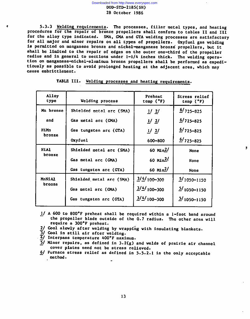
e 5.3.3 Welding requirements. The processes, filler metal types, and heatingprocedures for the repair of bronze propellers shall conform to tables 11 and IIIfor the alloy type indicated. SllA,G14Aand GTA welding procesaea are satisfactoryfor all ~jOr and n!JnOrrepaira on all typea of propellers. D%yfuel gas weldi~ie permttted on manganeae bronze and nickel~nganeae bronze propellers, but itshall be limited to the repair of edgea on the outer one-third nf the propellerradiua and in general to aectiona under 1-1/4 Inchee thick. The welding opera-tion cm manganeae-nickel-aluminum bronze propellera shall be performed aa expedi-tiouaiy aa poaaible to ovoid prolonged heating at the adjacent area. which mavcauae embrittlement.
TAMS III. Welding proceaaee and heating requirements.
Alloy Preheat Stress relieftype Welding proceaa temp (“F) temp “(‘F)
Hn bronze Shielded metal arc (SHA) II 21 kf725-825.-
and &a metal arc (GM) lf 2/ ~j~25-825——
Ni2fn &a tungsten arc (CTA) 1/ 2/ k~725-825bronze
—-
Oxyfuel 600-800 if725-825
NiA3 Shielded metal arc (51M) 60 M@ Nnnebronze
C8a metal arc (GM) 60 ni~~ None
Caa tungsten arc (CTA) 60 M@ None
!fnNiAl 3/4/lo&3f30Shielded.metal arc (SU@ __ Y105O-11SObronze
Cea metal arc (tWA) 2/1/100-300 2/1050-1150
Caa tungsten arc (CTA) ~1~1,o&3f30 2/1050-1150
~/ A 600 to 800”F preheat shall be required within a l-font band aroundthe propeller blade outside of the O.7 radiua. The other area willrequire a 300”P nrehent.
~/ Cool slnwly after-welding by wrappi”~ with insulating blamketa.3/ Cool in etill air after welding.~/ Interpaaa temperature 400”F maximum.~/ Minor repaire, se defined in 3.2(g) and welds of prairie air channel
cover platea need not be atreea relieved.~/ Furnace atreaa relief aa defined in 5.5.2.1 la the only acceptable
method.
13
Downloaded from http://www.everyspec.com

DOO-STO-2]85(M)28 October 1986
5.3.4 Repairs to critical areas. No welding in way of the critical areaof a blade is to ha undertaken without prior approvel by NAVSEA or authorizedrepresentative. Aa shown on figure 1, the critical area la defined as the areain the pressure face of the blade between the fillet and 0.4R and starting atthe leading edge encompassing 80 percent of the chord length taken at O.4R.Rapairs in these areaa shall be made by means of arc welding when approved.
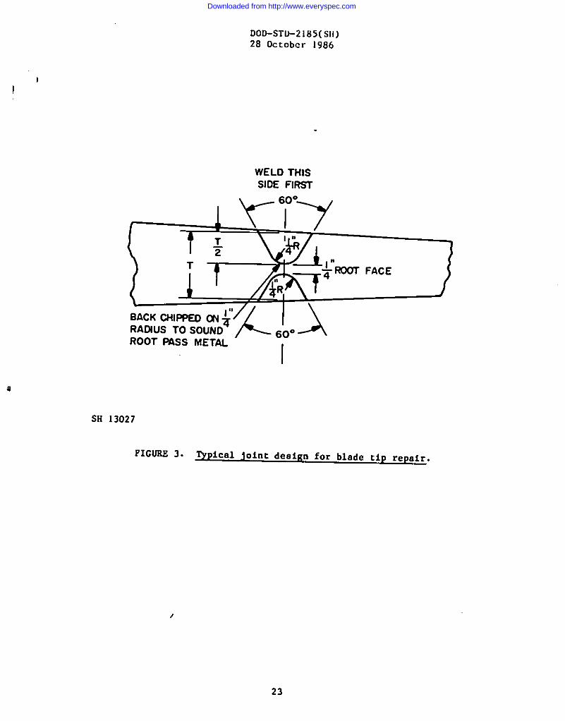
5.3.5 Joint design and position. Repairable defects shall be air-carbon-arced, chipped, or ground to sound m eta l , and recommendedgrooves (ace figures2 and 3) provided for welding in the flat (down hand) Position.
5.3.6 Peenin& All layers of weld ❑etal IMY be peened to help controldistortion or relieve atreaaes. Adequate propeller support shall be used whenpeening.of the first layer la performed. Peening of the last layer is permittedprovided this layer la subsequently ground to remove all evidence of peeningprior to visual and liquid penetrant inspection.
5.3.7 Rapair exceptions. The repair of defeccs by maana of soft aolderaor silver-brazingalloys shall not be permitted.
5.3.7.1 Small defects. Repair of small defecca for sake of appearanceabell be avoided. Caviciea with a maximum depth of 1/8-inch shall be leftundisturbed (ace 5.3.8).
5.3.8 Weld repair inspection. All welds shall be visually inspected afterweld repair and before etreae relief (if stress relief is required). Visualinspection is again required after atreas relief. Liquid penetrant inspection,in accordance with 141L-STD-271, shall be performed aa an aid to visual inspectionin locating discontinuities. Diacontinuities located by liquid penetrant inspec-tion shell ba evaluated for repair baaed on actual size of the discontinuity andnot on the indication size developed during the liquid penatrant Inspection.Weld repairs shall be evaluated in accordance with table I of NAVSEA0900-LP-O03-8000with the following exceptions:
(a) Combatant noise critical propellers. Surface porosity shallbe limited to 0.010 inch in size in a 1 inch wide band oneach face along the leading edge, and at the break of theknuckle along the trailing edge.
(b) All propellers. A propaller will be considered acceptableeven though it exceeds the limits epecified in table I ofNAVSEA 0900-LP+03-8000 under the folloving conditions:
(l) service and a.bsequent Inspection haa confinnad thatthere are no cracka in the affected erea. ‘Ihiamaybe in the original caating or previous weld repairareaa.
(2) Provided no actual cracks are detected, existing linearindication outside the weld repair area are acceptable.
,
I
(c) 5.3.8(a) takee precedence over 5.3.8(b).
14
Downloaded from http://www.everyspec.com

DOD-STD-2185(SH)28 October 1986
‘c
5.4 StraightenIn&.
s.4.1 General. The appropriate straighteningshall be followed in making repairs to the typee of
proceduresgiven in table IVpropell~r alloys listed.
5.4.2 Cold acraighteniq. tild straightening (temperaturebelsw 400”F) bymeans of dynamic loads @hell be used nnly to repair minor bends. The straight-ening operation, in the case of maaganeae bronze, nickel~nganeae bronze andcx?mganese-nickel-alumlnumbronze propellers, shall be followed by a suitablestrees relief treatment in accordance with table IV and 5.5.1 thrnugh 5.5.4.
TA8LS IV. Heating requiremence for scraighteni~
Loading!/ Straightening Streee reliefAlloy type Type of repair method temp “F temp “F
h bronze Minor Dynamic or 400 naxi?l ~/~25-825
elowly applied
Nitla U.innr Dynamic or 400 max?f !1725-825brnuze slowly applied
NiAl llinor Dynamic or 400 max Nnnebrnnze slowly applied
Plajoror minor 2/5j6/~40@~650Dynamic or --– None81OW1Y applied
linNiA2 Very minor only Dynamic or 400 max if 2IAI105O-115Obronze elowly applied
Flajnr or minnr Dynamic or 21!?II1450-1550 ilkl1(150-I150slewly applied Ifil1050-1150
~/ A dynamic load is nne which is mnving prior to contact with the propeller.A slnwly applied load ie in constant contact with the propeller whenecress is applied.
~/ Cool elowly after straightening.~/ Cool in still air after straightening and strees relief operetion.~/ Minor repaire as defined in 3.2(g) need noc be etress relieved.~j Temperature amst be reached and maintained during the complece straightening
operation.6/ In order to nbtain a temperaturewithin the 1400 tn 1650”F raWe the fOllO~-.
ing heating controls are recommended.(a) Heet with prnpane torchee for not less than 3 hours.(b) Heat should be applied over a large area and ehould extend
1-1/2 feet beyond the bend area.(c) Oxyacetylene torches ehnuld be used CO implement heating for
straightening.~/ A generous area in which straightening ie to be done ie to be heat
prior to applyiag load.~/ Purnace etress relief as defined in 5.5.2.1 is the only acceptable
soaked
method.
t
Downloaded from http://www.everyspec.com
DOD-S’I’O-2185(SN)28 October 1966
I1“
5.4.3 Hot straightenin&. Hot straighteningmmy only be applied as notedin table IV. The portion of the propeller which is being straightened should bekept within the recommended temperature range 8s specified in table IV duringthe course of the repair by means of soft gee torches (eoft neutral or slightlyreducing flame), supplementedwhen meceseary with heat from moving oxyacetylenetorches. A generous aree surrounding the iection to be straightened shall beheated through its entire thicknees to the required temperature. The requiredstraightening temperature and etress relief requirementsshall be in accordancewith table IV and 5.5.1 through 5.5.4.
5.4.6 Inspection after straightenin~ l%e straightening repairs shall bevisually inspected after straighteningand then again after etrees relief (ifstrese relief is required). Liquid penetrant inspection shell be performed asan aid to visual inspection in locating discontinuicies. The acceptance stan-dards and exception shall be as specified in 5.3.8.
5.5 Streaa relief.
5.5.1 General. Welding or straightening repaira made on manganese bronze,nickel-manganeeebronze and manganeae-nickel-aluminumbronze propellera shallbe streaa relieved within the appropriate temperature range shown in tablea 11and IV. Although the etreas relieving treatment ia usually carried out immedi-ately after repairing, no harm ie to be expected if the repaired area on mcnga-naae bronze or nickelmnganeae bronxe ia first allowed to cool slowly to roomtemperature by wrapping in an aabaetoa free insulation blanket. The heatingand cooling of manganeae-nickel-aluminumbronze shall be such aa to avoid the660 to 1050”F temperature range which may cauee embritclement. A atresarelieving treatment should be given aa coon aa practicable. A furnace atreaerelief ia required for all weld repaira and straighteningoperationa on manganeaebronze and nickelenganaae bronze baae material. For manganeae-dckel-aluminumbronze furnace atreea relief is atrengly recommendedwhere repalra in heavySeCtiOna or fillet areas have been made. Uanganeae and nickelanganeae bronxapropellers being recondicloned that have been in service over 7 yeara or thathave been In storage and cannot be certified aa having been otreaa relieved atthe time of reconditioningor prior to storage, to these requirements shall befurnace atreaa relieved. Nickel-aluminumbronze propellera do not require thestreaa relief treatment.
5.5.1.1 Menganeae-nickel-alumfnumbronza propellers. Streaa relieving ofmanganeae-ickel-aluminum bronze (auperaton 40) propellers is required aubaequentco straightening or weld repaira, except for the welds of prairie air channelcover platea and minor defects in noncritical areaa (ace 5.3.4).
5.5.2 Furnace etreaa relief.
5.5.2.1 Furnace atreas ralief of manganeae bronze and nickelenganeaebronxe. Furnace atreaa relief shall be accomplished by slow uniform heating toa holding tampemture of 725 to 825”F. Application of heat shall be controlled(a) ao that the he~ting rate doea not exceed 50”F per hour at any thermocoupleon the propeller; and (b) ao that a cempemture differential of 100”F ia notexceeded among any nf the attached therwcouplea. Time at the holding tempera-ture shell begin when all attached thermocouples are within 50”F of each other
16
Downloaded from http://www.everyspec.com

DDD-STD-2185@H)28 October 1986
and are vithin the 725 to 825”Y range. llrfscontrol (50”F mximum differentialwithin the 725 to 825°F range) shall be m aintaine d for a minimum of 12 hoursprior to the start of cooldown. Cooling shall be controlled (a) so that thecnoling rate does not exceed SO*F per hour at any thermocoupleon the propeller;and (b) so that a temperaturedifferential of 50”F is not exceeded smong theattached (without welding) thermocouples. Centrol of cooling and the monitoringof ternperatureeshall continue until the maximum temperatureof the thermocouplesattached to the hub is vithin 100”F of ambient air temperatureoutside thefurnnce.
5.5.2.2 Furnace stress relief of manganese-nickel-aluminumbronze. ltrismethod is recommended vhere possible and shall be accomplished by heating theentire propeller in a furnace. Streaa relief shell be effecced by slow unifocmheating co a holding temperature in the atrefiareliaf temperature range aarequired by cable 11 or IV. The heating rate shall be controlled ao that atemperaturegradient of 100”F la not exceeded among the thermocouplesattachedto the propeller for monitoring cemperaturaa. In addition, che surface onwhich the propeller ia placed shall be constructed in such a manner to permitcirculationof the hot gaaea through the propeller bore. Time at che holdingtemperatureshall sctrrtwhen all attached checmocouplearead within a tempera-ture differential of 100”F and are within the stresa relfeving range. ‘l’hisdegree of control shall be maintained during the holdiag period for a minimumof 12 hours prior co the start of cooling. Ouriag the cooling cycle, controlof the temperaturegradient shall be maintained so that the differential doesnoc exceed 50”F. 14enicoringof propeller temperatureshall continue until hubcamperaturesare within 100”F of ambient air temperatureoutside the furnace.
5.5.2.3 Temperature recording. A record of furnace air cemperatureaasveil as propeller temperature shell be obtained during the streea relief heatCreacmenc cycle at intervala not exceeding 1 hour. Fropeller te m p erature
shall be menltored by thermocoupleslocated in the followiag poaitiona:
(a) On the cop face of che hub.(b) On che bottom face of the hub.(c) At the center (mid-length) of the bore.(d) On the oucaide center (mid-lemgth) of the hub.(e) At the center (!3.6Rand mid-chord) of the pressure and suction
facea of tvn opposite bladea.(f) Within 1 inch of the tip at the centerline on the underside of
all bladea located to meaaure furnace ambient (air) temperature.(g) Located to maaaure furnace ambient (air) temperatureand furnaca
floor temperature.
5.5.2.3.1 Thecmncouple attacissenc. llcermocouplesshall be actsched to thepropeller in such a manner that their removal will not result in damage to theattachment areaa and they shall be insulated from che acmoapheric temperaturewirerewelding ia utilized in conjunction with maaganeae bronze or nickel-~Waneae brO@=e appropriate inspection ia to be made co ensure that no crackingha developed.
,
17
I
1
Downloaded from http://www.everyspec.com

.
DOO-STO-2185(SH)28 Ott’obcr1986
5.5.3 Local stress relief.
5.5.3.1 General. Lncal stress relief may be performed when furnace stressrelfef is not practical, or the scope of the veld repair is euch that furnacestress relief is not required. Lecal stress =elief may aleo be performed ifminor repairs are required after furnace strees relieving or when repairs(welding or straightening)have been partially accomplished but repair must beinterrupted and set aside for a period of time. In the latter case an interimlocal stress relief prior to furnace stress relief 18 recommended to minimizein-procese cracking. Local stress relief 10 not permitted on manganese bronzeand nickel-nnnganesebronze.
5.5.3.2 Major repairs. In order to effeet a suitable local stress relief,a band approximately 24 inches wide and extending across the entire width andthrough the entire chicknese of the blade shall be slowly heated to the stressrelieving temperature so that a temperature gradient of 100”F per foot is notexceeded outside this band. ‘lheband shell be so located that the repair areais on the centerline of the band width and the heating shall be accomplished bymeans of soft gas torches (eoft neutral slightly reducing flame) or electricalresistance (strip) heaters rather than by oxyacetylene torches. The holding(soaking) time at temperatureshall be at least 20 minutes per inch of basemetal thickness at the repaired area for manganese bronze or nickel~nganeaebronze propellers. The holding time for ❑anganese-mickel-aluminumbronzepropellers shall be nn longer than what la necessary to meet the minimum 20minutes per inch requirement. The repaired section of manganeae bronze ornickel~nganeae bronze propeller shall be slowly cooled ao that a temperaturegradient of 50”F per hour is not exceeded. Slow ceeling from the streaarelieving temperatureshall be accomplished by vrapping or covering with insu-lation blankets. The caeling of manganese-sickel-aluminumbronze shall be instill air at room temperature.
5.5.3.3 Minor repairs. For a local stress relief of minor repairs inareaa subject to low working atresaes, such aa the blade edges and tips, thestress relief treatment shall coneiat of a gradual spreading and maintaining ofthe heat by mcana of soft gaa torches or electrical resistance (strip) heatersin the repaired area so that the stress relief temperature extends through theentire thickneaa for a distance of about 12 inches on all sides of the repairedarea, vMle not exceeding a temperature gradient of about 100”F per foot.Cooling from the stress relief temperature shall be accomplished as stated in5.5.3.2.
5.5.4 Repeller support. Adequate support shall be provided during pre-heat, welding, straightening,or any stress relieving operation to minimizedistortion.
5.5.5 Grindin&. Ultengrindimg on manganese bronze or nickelmnganeaebronze, the contractor or shipyard shall meintain a temperature profile in thearea of grinding of 50”F maximum above ambient.
/6. NOTES
6.1 2stended use. This standard is used for repair and straightening ofbronze Naval ship propellers.
Downloaded from http://www.everyspec.com

DDD-STD-2185(SH)28 October 1986
{
6.2 Data requirements. When this standard is used in an acquisition whichincorporatesa DD Form 1423, Contract Oata RequirementsList (CDRL), the datarequirementsidentified below shall be developed as specified by an approved DataItem Description(DD Form 1664) and delivered in accordancewith the approvedCDRL incorporated into the contract. When th$ provisionsof OeD FAR Supplement,Part 27, Sub-Part 27.410-6 (DD Form 1423) are invoked and the DD Form 1423 is notused, the data specified below shmll be delivered by the contractor in accordancewith the contract or purchase order requirements. Deliverabledata required bythis standard are cited in the following paragraphs.
Paragraph no. Data requirement title Q@lcable DID no. Q2u4x!
4.2.3.1 and Snd item final inspec- DI-R-4809 --—
5.1.5.2.2 tion record4.3.1 Procedure, welding UDI-H-23383 —--4.3.2 Qualification data, UDI-H-2338fI --—
welding procedure
(Data item descriptions related to this standard, and identified in sec-tion 6 will h approved and listed as such in DnD SO1O.12-L., A14SDL. Cepiesof data item deacriptiona required by the contractors in connection with specificacquisition functions should be obtained from the Naval Publications and FormaCenter or as directed by the contracting officer.)
6.3 The quality control system should includewritten records of at least the following items:
(a)(b)
(c)
(d)(e)(f)
(g)(h)(i)(j)(k)(1)
Propeller identification (ship claas
preparing and maintaining
and aerial number).Material type, base and fille~, chemical analysia, and”alpha/beta check if required.~pe of repair (straightening or welding) includinglocation (face, radiua and chordvise location).Claaa of repair (minor or major).Repair procedure used.Heat treatment (include preheat, any interpass and post heattreatment). Post weld heat treatment data shall be collectedand provided in the form of graphical or tabulated temperatureveraua time data. The record shall be annotated vith thelocation and identification of the thecmecouples.Identificationof personnel performing repair and inspection.Inspection procedures used.Inspection ceaulta. Subsequent repairs shall be recorded.Diapoaition of repair.Microstructureanalysia when required with metallographic record.Weld repair documentation:
(l) Filler meterial(2) Subsequent repaira(3) Ijelderidentification(4) Welding datea
—.. . .
19
Downloaded from http://www.everyspec.com

M)D-sTo-2185(SH)28 October ]986
6.4 Subject term (key word) listin&.
Bronze propellers, weldingCavitation corrosionInspection,weld repairPropellers, welding requirementsStraightening,propellersWelder performance qualificationWelding procedures
6.5 Superseseion. ‘lMs document supersedes NAVSEA 0991-LP+23-3000,amendment 2 dated 15 July 1982, ACN 1/3 dated 19 July 1983, ACN 4 dated12 September 1984 and its clarification letter dated 18 Narch 1985.
Preparing activity:Navy - SH(Project 201O-NO24)
{
Downloaded from http://www.everyspec.com

DOD-STD-2185(SH)28 October 1986
L = CHORO LENGTH AT 0.4R
Sll13025/ .-....—.-
FIGUEE 1. Blade criticel eree.
Downloaded from http://www.everyspec.com

DOO-ST&2185(SH)28 October 1986
/
SK 13026
FIGURE 2. VP ical gouge preparation for veldinx repair.
(_
Downloaded from http://www.everyspec.com
DOD-STL)-2185(s}{)28 October 1986
I
!
WELD THISSIDE FIRW
~. 0.7
tTT
T
I
BACK CHIPPED ~ $RAOIUS TO SOUNDROOT PASS METAL
I
SH 13027
FICORE 3. VP ical joint desiKn for blade tip repair.
23
Downloaded from http://www.everyspec.com

I
I
I
I
i
III
I
IIII
IIII
III
-1I
II
III
I
I($
STANDARDIZATION 00CUMENT IMPROVEMENT PROPOSAL_.. ..—(See IIutrucfiom - Reverse .W.l
)OCUMEMTNUU8ER 1. 00CUMENT TITLE /ePair And Straightening OfK)o-sTo-2185(SH) R.m7eNAME OP 8U8MITTIN G oRO AUIZATIOW
& — Wadfw
REUAI+KS
I IDOo!%’.1426 PREv1OUJ ~ OITIO N m O#SOLCTS.
Downloaded from http://www.everyspec.com