Not-Aus-Modul BD 5987 - SAFEMASTER - Dold-PIM · 1 BD 5987 / 19.04.17 de / 962 SAFEMASTER...
44
1 BD 5987 / 19.04.17 de / 962 SAFEMASTER Not-Aus-Modul BD 5987 0262943 Datenblatt / Betriebsanleitung DEUTSCH E. DOLD & SÖHNE KG Postfach 1251 • 78114 Furtwangen • Deutschland Telefon +49 7723 6540 • Fax +49 7723 654356 [email protected] • www.dold.com Original DE EN FR IT
Transcript of Not-Aus-Modul BD 5987 - SAFEMASTER - Dold-PIM · 1 BD 5987 / 19.04.17 de / 962 SAFEMASTER...

1 BD 5987 / 19.04.17 de / 962
SAFEMASTER Not-Aus-Modul BD 5987
0262943
Datenblatt / Betriebsanleitung DEUTSCH
E. DOLD & SÖHNE KGPostfach 1251 • 78114 Furtwangen • DeutschlandTelefon +49 7723 6540 • Fax +49 7723 [email protected] • www.dold.com
Original
DE
EN
FR
IT
2 BD 5987 / 19.04.17 de / 962
Inhaltsverzeichnis
Symbol- und Hinweiserklärung ..........................................................................................................................................3
Allgemeine Hinweise ........................................................................................................................................................3
Bestimmungsgemäße Verwendung ...................................................................................................................................3
Sicherheitshinweise ...........................................................................................................................................................3
Produktbeschreibung .........................................................................................................................................................5
Funktionsdiagramm ...........................................................................................................................................................5
Blockschaltbild ...................................................................................................................................................................5
Zulassungen und Kennzeichen .........................................................................................................................................5
Anwendungen ....................................................................................................................................................................5
Geräteanzeigen .................................................................................................................................................................5
Schaltbilder ........................................................................................................................................................................6
Anschlussklemmen ............................................................................................................................................................6
Hinweise ............................................................................................................................................................................6
Technische Daten ..............................................................................................................................................................6
Technische Daten ..............................................................................................................................................................7
Standardtype .....................................................................................................................................................................7
Vorgehen bei Störungen ....................................................................................................................................................7
Wartung und Instandsetzung .............................................................................................................................................7
Varianten ...........................................................................................................................................................................7
Kennlinien ..........................................................................................................................................................................8
Anwendungsbeispiele ........................................................................................................................................................8
Anwendungsbeispiele ........................................................................................................................................................9
Beschriftung und Anschlüsse ..........................................................................................................................................41
Maßbild (Maße in mm) ....................................................................................................................................................41
Sicherheitstechnische Kenndaten ...................................................................................................................................42
EG-Konformitätserklärung ...............................................................................................................................................43
EG-Konformitätserklärung ...............................................................................................................................................44

3 BD 5987 / 19.04.17 de / 962
Sicherheitshinweise
WARNUNG
Gefahr durch elektrischen Schlag! Lebensgefahr oder schwere Verletzungsgefahr.• Stellen Sie sicher, dass Anlage und Gerät während der elektrischen Installation in spannungsfreiem Zustand sind und bleiben.• Das Gerät darf nur für die in der mitgeltenden Betriebsanleitung / Daten-
blatt vorgesehenen Einsatzfälle verwendet werden. Die Hinweise in den zugehörigen Dokumentationen müssen beachtet werden. Die zulässigen Umgebungsbedingungen müssen eingehalten werden.
• Der Berührungsschutz der angeschlossenen Elemente und die Isolation der Zuleitungen sind für die höchste am Gerät anliegende Spannung auszulegen.
• Beachten Sie die VDE- sowie die örtlichen Vorschriften, insbesondere hinsichtlich Schutzmaßnahmen.
WARNUNG
Brandgefahr oder andere thermische Gefahren! Lebensgefahr, schwere Verletzungsgefahr oder Sachschäden.• Das Gerät darf nur für die in der mitgeltenden Betriebsanleitung / Daten-
blatt vorgesehenen Einsatzfälle verwendet werden. Die Hinweise in den zugehörigen Dokumentationen müssen beachtet werden. Die zulässigen Umgebungsbedingungen müssen eingehalten werden. Insbesondere muss die Stromgrenzkurve beachtet werden.
• Das Gerät darf nur von sachkundigen Personen installiert und in Betrieb genommen werden, die mit dieser technischen Dokumentation und den geltenden Vorschriften über Arbeitssicherheit und Unfallverhütung vertraut sind.
WARNUNG
Funktionsfehler! Lebensgefahr, schwere Verletzungsgefahr oder Sachschäden.• Das Gerät darf nur für die in der mitgeltenden Betriebsanleitung / Daten-
blatt vorgesehenen Einsatzfälle verwendet werden. Die Hinweise in den zugehörigen Dokumentationen müssen beachtet werden. Die zulässigen Umgebungsbedingungen müssen eingehalten werden.
• Das Gerät darf nur von sachkundigen Personen installiert und in Betrieb genommen werden, die mit dieser technischen Dokumentation und den geltenden Vorschriften über Arbeitssicherheit und Unfallverhütung vertraut sind.
• Montieren Sie das Gerät in einen Schaltschrank mit Schutzart IP 54 oder besser (nicht zwingend erforderlich für die Variante BD 5987.02/301 bei Einsatz in einer Aufzugsanlage nach Aufzugsrichtlinie 2014/33/EU. Der Einsatz ist beschränkt auf einen stationären Schaltschrank - Einsatz nicht auf dem Fahrkorb. Umwelteinflüsse am Einbauort dürfen dabei keine negativen Auswirkungen auf die Funktion der Schaltung haben. Siehe auch Fußnote 1 im Abschnitt "Technische Daten" und Anwen- dungsbeispiele M10429_a, M6899_c und M11384); Staub und Feuch- tigkeit können sonst zur Beeinträchtigungen der Funktionen führen.
WARNUNG
Installationsfehler! Lebensgefahr, schwere Verletzungsgefahr oder Sachschäden. • Sorgen Sie an allen Ausgangskontakten bei kapazitiven und induktiven
Lasten für eine ausreichende Schutzbeschaltung.
! Achtung! • Die Sicherheitsfunktion muss bei Inbetriebnahme des Gerätes ausgelöst werden.• Entsteht ein Leitungsschluss über dem Ein-Taster nachdem die Span- nung an S12, S22 bereits anliegt, erfolgt eine ungewollte Aktivierung, weil sich dieser Leitungsschluss von der regulären Einschaltfunktion nicht unterscheidet.• AUTOMATISCHER START ! Gemäß IEC/EN 60 204-1 Punkt 9.2.5.4.2 darf nach dem Stillsetzen im Notfall kein automatischer Start erfolgen. Deshalb muss in den Betriebs- arten mit automatischem Start, eine übergeordnete Steuerung einen automatischen Start nach einem Not-Aus verhindern.• Durch Öffnen des Gehäuses oder eigenmächtige Umbauten erlischt jegliche Gewährleistung.
GEFAHR: Bedeutet, dass Tod oder schwere Körperverletzung eintreten
wird, wenn die entsprechenden Vorsichtsmaßnahmen nicht ge-troffen werden.
WARNUNG: Bedeutet, dass Tod oder schwere Körperverletzung eintreten
kann, wenn die entsprechenden Vorsichtsmaßnahmen nicht getroffen werden.
VORSICHT: Bedeutet, dass eine leichte Körperverletzung eintreten kann,
wenn die entsprechenden Vorsichtsmaßnahmen nicht getroffen werden.
! ACHTUNG:
Warnt vor Handlungen, die einen Schaden oder eine Fehlfunktion des Gerätes, der Geräteumgebung oder der Hard-/Software zur Folge haben können.
nfo Hinweis:
Bezeichnet Informationen, die Ihnen bei der optimalen Nutzung des Produktes behilflich sein sollen.
Die hier beschriebenen Produkte wurden entwickelt, um als Teil einer Gesamtanlage oder Maschine sicherheitsgerichtete Funktionen zu über-nehmen. Ein komplettes sicherheitsgerichtetes System enthält in der Regel Sensoren, Auswerteeinheiten, Meldegeräte und Konzepte für si-chere Abschaltungen. Es liegt im Verantwortungsbereich des Herstellers einer Anlage oder Maschine die korrekte Gesamtfunktion sicherzustellen. DOLD ist nicht in der Lage, alle Eigenschaften einer Gesamtanlage oder Maschine, die nicht durch DOLD konzipiert wurde, zu garantieren. Das Gesamtkonzept der Steuerung, in die das Gerät eingebunden ist, ist vom Benutzer zu validieren. DOLD übernimmt auch keine Haftung für Empfeh-lungen, die durch die nachfolgende Beschreibung gegeben bzw. impliziert werden. Aufgrund der nachfolgenden Beschreibung können keine neuen, über die allgemeinen DOLD-Lieferbedingungen hinausgehenden Garan-tie-, Gewährleistungs- oder Haftungsansprüche abgeleitet werden.
Allgemeine Hinweise
Symbol- und Hinweiserklärung
Bestimmungsgemäße Verwendung
Das BD 5987 dient dem sicherheitsgerichteten Unterbrechen eines Sicher-heitsstromkreises. Es kann zum Schutz von Personen und Maschinen in Anwendungen mit Not-Halt-Tastern und Schutztüren verwendet werden.Das BD 5987.02/301 kann als elektronische Sicherheitsschaltung zum Ersatz eines Sicherheitsschalters gem. EN 81-20, Abschnitt 5.11.2.2 ver-wendet werden. Applikationen entsprechend der Anwendungsbeispiele M10429_a, M6899_c und M11384.Bei bestimmungsgemäßer Verwendung und Beachtung dieser Anleitung sind keine Restrisiken bekannt. Bei Nichtbeachtung kann es zu Personen- und Sachschäden kommen.
Installation nur durch Elektrofachkraft!
Nicht im Hausmüll entsorgen! Das Gerät ist in Übereinstimmung mit den national gültigen Vorgaben und Bestimmungen zu entsorgen.
Aufbewahren für späteres Nachschlagen
Um Ihnen das Verständnis und das Wiederfinden bestimmter Textstellen und Hinweise in der Betriebsanleitung zu erleichtern, haben wir wichtige Hinweise und Informationen mit Symbolen gekennzeichnet.
Vor der Installation, dem Betrieb oder der Wartung des Gerätes muss diese Anleitung gelesen und verstanden werden.

4 BD 5987 / 19.04.17 de / 962
5 BD 5987 / 19.04.17 de / 962
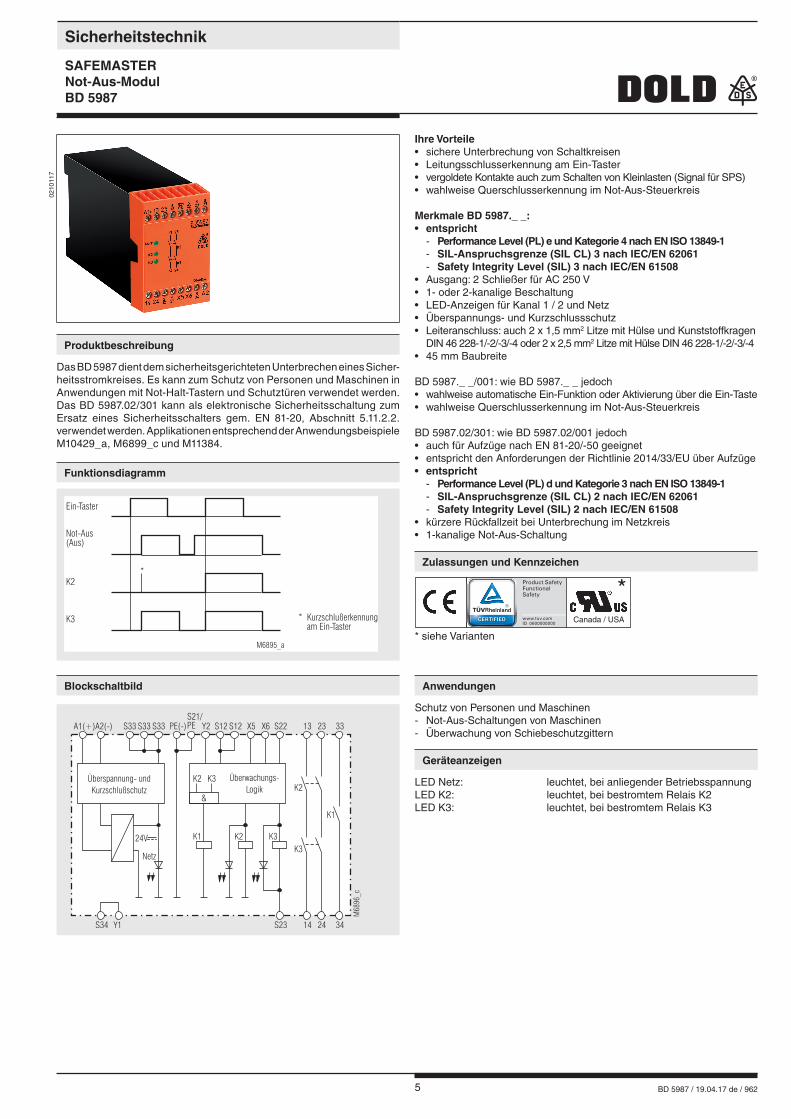
Ihre Vorteile• sichere Unterbrechung von Schaltkreisen• Leitungsschlusserkennung am Ein-Taster• vergoldete Kontakte auch zum Schalten von Kleinlasten (Signal für SPS)• wahlweise Querschlusserkennung im Not-Aus-Steuerkreis
Merkmale BD 5987._ _:• entspricht
- Performance Level (PL) e und Kategorie 4 nach EN ISO 13849-1 - SIL-Anspruchsgrenze (SIL CL) 3 nach IEC/EN 62061 - Safety Integrity Level (SIL) 3 nach IEC/EN 61508
• Ausgang: 2 Schließer für AC 250 V• 1- oder 2-kanalige Beschaltung• LED-Anzeigen für Kanal 1 / 2 und Netz• Überspannungs- und Kurzschlussschutz• Leiteranschluss: auch 2 x 1,5 mm2 Litze mit Hülse und Kunststoffkragen DIN 46 228-1/-2/-3/-4 oder 2 x 2,5 mm2 Litze mit Hülse DIN 46 228-1/-2/-3/-4• 45 mm Baubreite BD 5987._ _/001: wie BD 5987._ _ jedoch• wahlweise automatische Ein-Funktion oder Aktivierung über die Ein-Taste• wahlweise Querschlusserkennung im Not-Aus-Steuerkreis BD 5987.02/301: wie BD 5987.02/001 jedoch• auch für Aufzüge nach EN 81-20/-50 geeignet• entspricht den Anforderungen der Richtlinie 2014/33/EU über Aufzüge• entspricht
- Performance Level (PL) d und Kategorie 3 nach EN ISO 13849-1 - SIL-Anspruchsgrenze (SIL CL) 2 nach IEC/EN 62061 - Safety Integrity Level (SIL) 2 nach IEC/EN 61508
• kürzere Rückfallzeit bei Unterbrechung im Netzkreis• 1-kanalige Not-Aus-Schaltung
0210
117
Sicherheitstechnik
SAFEMASTER Not-Aus-ModulBD 5987
Produktbeschreibung
Das BD 5987 dient dem sicherheitsgerichteten Unterbrechen eines Sicher-heitsstromkreises. Es kann zum Schutz von Personen und Maschinen in Anwendungen mit Not-Halt-Tastern und Schutztüren verwendet werden.Das BD 5987.02/301 kann als elektronische Sicherheitsschaltung zum Ersatz eines Sicherheitsschalters gem. EN 81-20, Abschnitt 5.11.2.2. verwendet werden. Applikationen entsprechend der Anwendungsbeispiele M10429_a, M6899_c und M11384.
Funktionsdiagramm
Blockschaltbild
Zulassungen und Kennzeichen
Anwendungen
Schutz von Personen und Maschinen - Not-Aus-Schaltungen von Maschinen - Überwachung von Schiebeschutzgittern
Geräteanzeigen
LED Netz: leuchtet, bei anliegender BetriebsspannungLED K2: leuchtet, bei bestromtem Relais K2LED K3: leuchtet, bei bestromtem Relais K3
Ein-Taster
K2
M6895_a
K3 * Kurzschlußerkennungam Ein-Taster
*
Not-Aus(Aus)
A1(+)A2(-) S33 PE(-)S33S33 Y2 S12 S12S21/PE S22X6X5 332313
M68
96_c
S34 Y1 34S23 2414
K2K1K3
K2
K1
Netz
24V K3
Überspannung- undKurzschlußschutz
Überwachungs-Logik
K2 K3
&
* siehe Varianten
Canada / USA
*
6 BD 5987 / 19.04.17 de / 962
Eingang
Nennspannung UN: AC 24, 42, 48, 110, 127, 230, 240 V 1)
DC 24 VSpannungsbereich: AC 0,8 ... 1,1 UN
bei 10% Restwelligkeit: DC 0,9 ... 1,2 UN
bei 48% Restwelligkeit: DC 0,8 ... 1,1 UN
Nennverbrauch: ca. 5,5 VANennfrequenz: 50 / 60 HzSteuerspannung an S33: DC 24 VSteuerstromBD 5987.02: typ. DC 55 mABD 5987.02/001 + /301: typ. DC 45 mAMindestspannungan Klemmen S12, S22: DC 21 V bei aktiviertem GerätWiederbereitschaftszeit: 0,5 s nach Entriegelung der Not-Aus-Taste
Ausgang
Kontaktbestückung BD 5987.02: 2 SchließerBD 5987.03: 2 Schließer, 1 Schließer als Meldekontakt
Der Schließer 33-34 ist nur als Meldekontakt verwendbar
Ansprechzeit: max. 100 msBD 5987.02/001 + /301: bei automatischem Start ca. 1 sRückfallzeitbei 2-kanaliger Unterbrechung im Sekundärkreis (S12, S22 und S23): 50 ms ± 25 %bei Unterbrechung im NetzkreisBD 5987.02: 350 ms ± 50 %BD 5987.02/001: 120 ms ± 50 %BD 5987.02/301: 40 ms ± 50 %Fehlererkennungszeit bei UN:bei 1-kanaliger Unterbrechungin S12:BD 5987: typ. 430 msBD 5987/001+/201: typ. 85 msin S22 und S23: 50 ms ± 25 %Kontaktart: Relais, zwangsgeführtAusgangsnennspannung: AC 250 V 1)
DC: siehe LichtbogengrenzkurveThermischer Strom Ith: siehe Dauerstromgrenzkurve (max. 10 A in einem Kontaktstrang)SchaltvermögenKontakte 13/14, 23/24:nach AC 15: 5 A / AC 230 V 1) IEC/EN 60 947-5-1nach DC 13: 4 A / DC 24 V IEC/EN 60 947-5-1Kontakt 33/34:nach AC 15: 3 A / AC 230 V IEC/EN 60 947-5-1Elektrische Lebensdauer:nach AC 15 bei 2 A, AC 230 V: 105 Schaltspiele IEC/EN 60947-5-1Zulässige Schalthäufigkeit: 600 Schaltspiele / h
1) max. AC 160 V bzw. max. DC 160 V für die Variante BD 5987.02/301 bei Einsatz in einer Aufzugsanlage nach Aufzugsrichtlinie 2014/33/EU, wenn das BD 5987.02/301 nicht in einem Schaltschrank mit Schutzart IP 54 oder besser montiert wird.Kurzschlussfestigkeitmax. Schmelzsicherung: 6 A gL IEC/EN 60947-5-1Mechanische Lebensdauer: 10 x 106 Schaltspiele
Allgemeine Daten
Nennbetriebsart: DauerbetriebTemperaturbereich:Betrieb: - 15 ... + 55°C Lagerung : - 25 ... + 85 °CBetriebshöhe: < 2.000 m bei max. 90% LuftfeuchteLuft- und KriechstreckenBemessungsstoßspannung /Verschmutzungsgrad: 4 kV / 2 (Basisisolierung) IEC 60 664-1EMV: IEC/EN 62 061Funkentstörung: Grenzwert Klasse B EN 55 011SchutzartGehäuse: IP 40 IEC/EN 60 529Klemmen: IP 20 IEC/EN 60 529
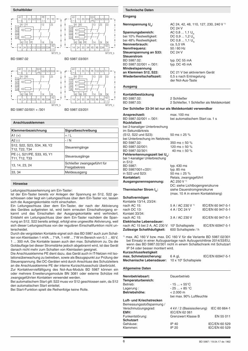
Schaltbilder
Anschlussklemmen
Klemmenbezeichnung SignalbeschreibungA1 (+) + / L
A2 (-) - / N
S12, S22, S23, S34, X6, Y2 T12, T22, T34
Steuereingänge
PE (-), S21/PE, S33, X5, Y1 T11, T12, T33
Steuerausgänge
13, 14, 23, 24Schließer zwangsgeführt für Freigabekreis
33, 34 Meldeausgang
Hinweise
Leitungsschlusserkennung am Ein-Taster:Ist der Ein-Taster bereits vor Anlegen der Spannung an S12, S22 ge-schlossen oder liegt ein Leitungsschluss über dem Ein-Taster vor, lassen sich die Ausgangskontakte nicht einschalten.Ein Leitungsschluss über dem Ein-Taster, der nach der Aktivierung des Gerätes aufgetreten ist, wird beim erneuten Einschaltvorgang er-kannt und das Einschalten der Ausgangskontakte wird verhindert. Entsteht ein Leitungsschluss über dem Ein-Taster nachdem die Span-nung an S12, S22 bereits anliegt, erfolgt eine ungewollte Aktivierung, weil sich dieser Leitungsschluss von der regulären Einschaltfunktion nicht un-terscheidet.Durch die vergoldeten Kontakte eignet sich das BD 5987 auch zum Schal-ten von Kleinlasten 1 mVA ... 7 VA, 1 mW ... 7 W im Bereich von 0,1 ... 60 V, 1 ... 300 mA. Die Kontakte lassen auch den max. Schaltstrom zu. Da die Goldauflage bei dieser Stromstärke jedoch abgebrannt wird, ist das Gerät danach nicht mehr zum Schalten von Kleinlasten geeignet.Die Anschlussklemme PE dient dazu, das Gerät auch in IT-Netzen mit Iso-lationsüberwachung zu betreiben, sowie als Bezugspunkt zur Prüfung der Steuerspannung. Bei DC-Geräten wird durch Anschluss des Schutzleiters an die Anschlussklemme PE der interne Kurzschlussschutz überbrückt.Zur Kontaktvervielfältigung des Not-Aus-Moduls BD 5987 können ein oder mehrere Erweiterungsmodule BN 3081 oder externe Schütze mit zwangsgeführten Kontakten verwendet werden.Bei automatischem Start gilt: S22 muss vor S12 geschlossen sein, da S12 den automatischen Start einleitet.Bei Start-Funktion spielt die Reihenfolge keine Rolle.
Technische Daten
K3
K2
Y2 PE
A1 Y1
S33
S12
S22
S34
A2
23
2414
13
S12 S12 S34
S33
S33 S33
A1(+)
PE(-)
S22
14 24
Y113 23 Y2
A2(-)
M7375_b
K3
K2
K1
X6 PE
A1 X5
S33
S12
S22
S34
A2
23
24 34
33
14
13
33 S34
S21/PE
34 X6X5
A1(+)
S22S12
14 24
S2313 23 S33
A2(-)
M7378_b
K3
K2
X6 PE
A1 X5
S33
S12
S22
S34
A2
23
2414
13
S12 S34
S21/PE
S33 X6X5
A1(+)
S22S12
14 24
S2313 23 S33
A2(-)
M7376_b
K3
K2
K1
X6 PE
A1 T11
T33
T12
T22
T34
A2
23
24 34
33
14
13
33 T34
PE
34 X6T33
A1(+)
T22T12
14 24
S2313 23 T11
A2(-)
M7379_c
BD 5987.02 BD 5987.03/001
BD 5987.02/001 + /301 BD 5987.03/201
7 BD 5987 / 19.04.17 de / 962
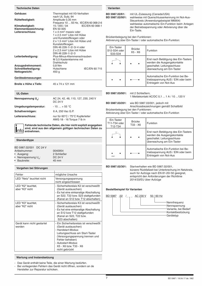
Gehäuse: Thermoplast mit V0-Verhalten nach UL Subj. 94Rüttelfestigkeit: Amplitude 0,35 mm Frequenz 10 ... 55 Hz, IEC/EN 60 068-2-6Klimafestigkeit: 15 / 055 / 04 IEC/EN 60 068-1Klemmenbezeichnung: EN 50 005Leiteranschluss: 1 x 4 mm2 massiv oder 1 x 2,5 mm2 Litze mit Hülse und Kunststoffkragen oder 2 x 1,5 mm2 Litze mit Hülse und Kunststoffkragen DIN 46 228-1/-2/-3/-4 oder 2 x 2,5 mm2 Litze mit Hülse DIN 46 228-1/-2/-3Leiterbefestigung: Plus-Minus-Klemmenschrauben M 3,5 Kastenklemme mit DrahtschutzAnzugsdrehmoment: 0,8 NmSchnellbefestigung: Hutschiene IEC/EN 60 715Nettogewicht: 450 g
Geräteabmessungen
Breite x Höhe x Tiefe: 45 x 74 x 121 mm
Technische Daten
Standardtype
BD 5987.02/001 DC 24 VArtikelnummer: 0040954• Ausgang: 2 Schließer• Nennspannung UN: DC 24 V• Baubreite: 45 mm
BD 5987.02/61: mit UL-Zulassung (Canada/USA)BD 5987.02/001: wahlweise mit Querschlusserkennung im Not-Aus- Steuerkreis (Anwendungsbeispiel M6904) wahlweise automatische Ein-Funktion beim Anlegen der Betriebsspannung oder Aktivierung über die Ein-Taste.
Brückenbelegung bei den Funktionen:Aktivierung über Ein-Taster / oder automatische Ein-Funktion:
M8687
Ein-TasterS12-S34 oder
S33-S34
BrückeX5 - X6
Funktion
Erst nach Betätigung des Ein-Tasters werden die Ausgangskontakte geschaltet. Leitungsschluss- überwachung am Ein-Taster
Automatische Ein-Funktion bei Be-triebsspannung AUS / EIN oder beim Entriegeln von Not-Aus
BD 5987.03/001: mit 2 Schließern, 1 Meldekontakt AC/DC 0,1 ... 1 A / 10 ...120 V
BD 5987.03/201: wie BD 5987.03/001, jedoch mit Anschlussbezeichnungen gemäß SchaltbildBrückenbelegung bei den Funktionen:Aktivierung über Ein-Taster / oder automatische Ein-Funktion
M8687
Ein-TasterT11-T34 oder
T12-T34
BrückeT33 - X6
Funktion
Erst nach Betätigung des Ein-Tasters werden die Ausgangskontakte geschaltet. Leitungsschluss- überwachung am Ein-Taster
Automatische Ein-Funktion bei Be-triebsspannung AUS / EIN oder beim Entriegeln von Not-Aus
BD 5987.02/301: Startverhalten wie BD 5987.02/001, kürzere Rückfallzeit bei Unterbrechung im Netzkreis, auch für Aufzüge nach EN 81-20/-50 geeignet, entspricht den Anforderungen der Richtlinie 2014/33/EU über Aufzüge
Bestellbeispiel für Varianten
BD 5987 .02 /_ _ _ AC 230 V 50 / 60 Hz
Nennfrequenz Nennspannung Variante, bei Bedarf Kontaktbestückung Gerätetyp
Varianten
Vorgehen bei Störungen
Fehler mögliche Ursache
LED "Netz" leuchtet nicht Versorgungsspannungnicht angeschlossen
LED "K2" leuchtet, aber "K3" nicht
- Sicherheitsrelais K2 ist verschweißt (Gerät austauschen) - Es hat eine einkanalige Abschaltung an S22, T22 bzw. S23 stattgefunden (Kanal an S12 bzw. T12 abschalten)
LED "K3" leuchtet, aber "K2" nicht
- Sicherheitsrelais K3 ist verschweißt (Gerät austauschen) - Es hat eine einkanalige Abschaltung an S12 bzw T12 stattgefunden (Kanal an S22, T22 bzw. S23 abschalten)
Gerät kann nicht gestartet werden
- Ein Sicherheitsrelais ist verschweißt (Gerät austauschen) - Handstart-Modus: Leitungsschluss am Start-Taster (Versorgungspannung trennen und Fehler beheben) - Autostart-Modus: X5 - X6 bzw. T33 - X6 nicht gebrückt
Wartung und Instandsetzung
- Das Gerät enthält keine Teile, die einer Wartung bedürfen. - Bei vorliegenden Fehlern das Gerät nicht öffnen, sondern an de
Hersteller zur Reparatur schicken.
Nennspannung UN: AC 24, 42, 48, 110, 127, 230, 240 V DC 24 V
Umgebungstemperatur: - 15 … + 55 °C
Schaltvermögen: 6 A, 250 Vac G.P.
Leiteranschluss: nur für 60°C / 75°C Kupferleiter AWG 18 - 16 Torque 7 lb in
nfoFehlende technische Daten, die hier nicht explizit angegeben sind, sind aus den allgemein gültigen technischen Daten zu entnehmen.
UL-Daten
8 BD 5987 / 19.04.17 de / 962
Kennlinien Anwendungsbeispiele
L1
M6898_bN
Not-Aus
A2(-)
A1(+) S33S34 S33 S33 PE(-) Y2 S12 S12 S22
Y1
BD5987
13 23
14 24
Ein
L1
M6900_bN
A2(-)
A1(+) S33S34 S33 S33 PE(-) Y2 S12 S12 S22
BD5987
Ein
Aus
Not-Aus
Y1
13 23
14 24
L1
M10429_a
A1(+)
BD5987.02/301
Aus
Not-Aus
N
A2(-) X5 X6 S34 14 24
Ein
S12 S12 S22 S21 S23 S33 13 23
S33
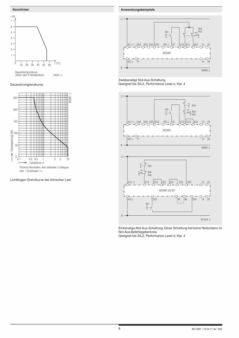
Zweikanalige Not-Aus-Schaltung.Geeignet bis SIL3, Performance Level e, Kat. 4
Einkanalige Not-Aus-Schaltung. Diese Schaltung hat keine Redundanz im Not-Aus-Befehlsgeberkreis.Geeignet bis SIL2, Performance Level d, Kat. 3
1
010
Dauerstromgrenzkurve(Strom über 2 Kontaktreihen)
20 30 40 50T ( C)�
60
M6897_a
2
3
4
5
6
7
I (A)
Dauerstromgrenzkurve
Lichtbogen-Grenzkurve bei ohmscher Last
00,1 0,3 0,5 1 3 5 10
Schaltstrom A
50
100
150
250
200
Scha
ltspa
nnun
gVD
C
M20
01_c
Sicheres Abschalten, kein stehender Lichtbogen,max. 1 Schaltspiel / s
9 BD 5987 / 19.04.17 de / 962
Anwendungsbeispiele
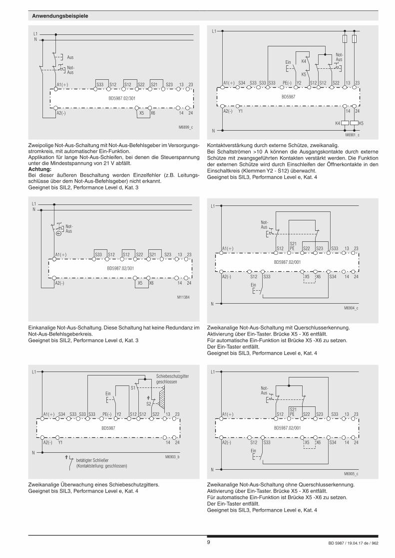
Zweipolige Not-Aus-Schaltung mit Not-Aus-Befehlsgeber im Versorgungs-stromkreis, mit automatischer Ein-Funktion.Applikation für lange Not-Aus-Schleifen, bei denen die Steuerspannung unter die Mindestspannung von 21 V abfällt.Achtung:Bei dieser äußeren Beschaltung werden Einzelfehler (z.B. Leitungs-schlüsse über dem Not-Aus-Befehlsgeber) nicht erkannt.Geeignet bis SIL2, Performance Level d, Kat. 3
Kontaktverstärkung durch externe Schütze, zweikanalig.Bei Schaltströmen >10 A können die Ausgangskontakte durch externe Schütze mit zwangsgeführten Kontakten verstärkt werden. Die Funktion der externen Schütze wird durch Einschleifen der Öffnerkontakte in den Einschaltkreis (Klemmen Y2 - S12) überwacht.Geeignet bis SIL3, Performance Level e, Kat. 4
Einkanalige Not-Aus-Schaltung. Diese Schaltung hat keine Redundanz im Not-Aus-Befehlsgeberkreis.Geeignet bis SIL2, Performance Level d, Kat. 3
Zweikanalige Not-Aus-Schaltung mit Querschlusserkennung.Aktivierung über Ein-Taster. Brücke X5 - X6 entfällt.Für automatische Ein-Funktion ist Brücke X5 -X6 zu setzen. Der Ein-Taster entfällt.Geeignet bis SIL3, Performance Level e, Kat. 4
Zweikanalige Überwachung eines Schiebeschutzgitters.Geeignet bis SIL3, Performance Level e, Kat. 4
Zweikanalige Not-Aus-Schaltung ohne Querschlusserkennung.Aktivierung über Ein-Taster. Brücke X5 - X6 entfällt.Für automatische Ein-Funktion ist Brücke X5 -X6 zu setzen. Der Ein-Taster entfällt.Geeignet bis SIL3, Performance Level e, Kat. 4
L1
M6901_cN
Not-Aus
A2(-)
A1(+) S33S34 S33 S33 PE(-) Y2 S12 S12 S22
Y1
BD5987
13 23
14 24
K4
K5
Ein
K4 K5M6899_c
Aus
Not-Aus
L1
A1(+)
BD5987.02/301
N
A2(-) X5 X6 14 24
S12 S22S12 S21 S23S33 13 23
M11384
Not-Aus
L1
A1(+)
BD5987.02/301
N
A2(-) X5 X6 14 24
S12 S22S12 S21 S23S33 13 23
L1
M6904_cN
Not-Aus
A2(-)
A1(+)S21PE S33S23S22S12
X5S33S12 X6 S34
BD5987.02/001
13 23
14 24
Ein
L1
M6903_bN
A2(-)
A1(+) S33S34 S33 S33 PE(-) Y2 S12 S12 S22
Y1
BD5987
13 23
14 24
Ein
betätigter Schließer(Kontaktstellung: geschlossen)
S1
S2
Schiebeschutzgittergeschlossen
L1
M6905_cN
Not-Aus
A2(-)
A1(+)S21PE S33S23S22S12
X5S33S12 X6 S34
BD5987.02/001
13 23
14 24
Ein

10 BD 5987 / 19.04.17 de / 962
E. DOLD & SÖHNE KG • D-78114 Furtwangene-mail: [email protected] • internet: http://www.dold.com
• Postfach 1251 • Telefon 0 77 23 / 654-0 • Telefax 0 77 23 / 654-356
11 BD 5987 / 19.04.17 en / 962
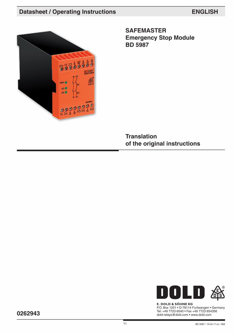
SAFEMASTER Emergency Stop Module BD 5987
Datasheet / Operating Instructions ENGLISH
E. DOLD & SÖHNE KGP.O. Box 1251 • D-78114 Furtwangen • GermanyTel: +49 7723 6540 • Fax +49 7723 [email protected] • www.dold.com
Translation of the original instructions
0262943

12 BD 5987 / 19.04.17 en / 962
Contents
Symbol and Notes Statement ..........................................................................................................................................13
General Notes .................................................................................................................................................................13
Designated Use ...............................................................................................................................................................13
Safety Notes ....................................................................................................................................................................13
Product Description .........................................................................................................................................................15
Fucntion Diagram ............................................................................................................................................................15
Block Diagram .................................................................................................................................................................15
Approvals and Markings ..................................................................................................................................................15
Applications .....................................................................................................................................................................15
Indication .........................................................................................................................................................................15
Circuit Diagrams ..............................................................................................................................................................16
Connection Terminals ......................................................................................................................................................16
Notes ...............................................................................................................................................................................16
Technical Data .................................................................................................................................................................16
Technical Data .................................................................................................................................................................17
Standard Type ..................................................................................................................................................................17
Troubleshooting ...............................................................................................................................................................17
Maintenance and repairs .................................................................................................................................................17
Variants ............................................................................................................................................................................17
Characteristics .................................................................................................................................................................18
Application Examples ......................................................................................................................................................18
Application Examples ......................................................................................................................................................19
Labeling and connections ................................................................................................................................................41
Dimensions (dimensions in mm) .....................................................................................................................................41
Safety Related Data ........................................................................................................................................................42
CE-Declaration of Conformity ..........................................................................................................................................43
CE-Declaration of Conformity ..........................................................................................................................................44
13 BD 5987 / 19.04.17 en / 962
Safety Notes
WARNING
Risk of electrocution! Danger to life or risk of serious injuries. • Disconnect the system and device from the power supply and ensure they remain disconnected during electrical installation.• The device may only be used for the applications described in the mu-
tually applicable operating instructions / data sheet. The notes in the respective documentation must be heeded. The permissible ambient conditions must be observed.
• The contact protection of the elements connected and the insulation of the supply cables must be designed in accordance with the requirements in the operating instructions / data sheet.
• Note the VDE and local regulations, particularly those related to protec-tive measures.
WARNING
Risk of fire or other thermal hazards! Danger to life, risk of serious injuries or property damage. • The device may only be used for the applications described in the mutually
applicable operating instructions / data sheet. The notes in the respective documentation must be heeded. The permissible ambient conditions must be observed. In particular, the current limit curve must be heeded.
• The device may only be installed and put into operation by experts who are familiar with this technical documentation and the applicable health and safety and accident prevention regulations.
WARNING
Functional error! Danger to life, risk of serious injuries or property damage. • The device may only be used for the applications described in the mu-
tually applicable operating instructions / data sheet. The notes in the respective documentation must be heeded. The permissible ambient conditions must be observed.
• The device may only be installed and put into operation by experts who are familiar with this technical documentation and the applicable health and safety and accident prevention regulations.
• The unit should be panel mounted in an enclosure rated at IP 54 or superior (not neccessary for variant BD5987.02/301 when used in an elevator control according to elevator directive 2014/33/EU. The usage is limited to the application in stationary cabinets - not in the lift cabin. Ambient conditions at the place of installation must not have a negative influence to function of the circuit. See also note 1 in section " technical data" and application examples M10430_a, M6745_b and M11385). Dust and dampness may lead to malfunction.
WARNING
Installation fault! Danger to life, risk of serious injuries or property damage. • Make sure of sufficient protection circuitry at all output contacts for
capacitive and inductive loads.
! Attention! • The safety function must be triggered during commissioning.• If a line fault occurs at the On pushbutton after the voltage is already present at S12, S22 undesired activation will take place, because this line fault does not differ from the normal closing function.• AUTOMATIC START ! According to IEC/EN 60 204-1 part 9.2.5.4.2 and 10.8.3 it is not allowed to restart automatically after emergency stop. Therefore the machine control has to disable the automatic start after emergency stop.• Opening the device or implementing unauthorized changes voids any warranty
DANGER
DANGER: Indicates that death or severe personal injury will result if
proper precautions are not taken.
WARNING
WARNING: Indicates that death or severe personal injury can result if
proper precautions are not taken.
CAUTION
CAUTION: Indicates that a minor personal injury can result if proper
precautions are not taken.
! ATTENTION:
Warns against actions that can cause damage or malfunction of the device, the device environment or the hardware / software result.
nfo INFO:
Referred information to help you make best use of the product.
Symbol and Notes Statement
The installation must only be done by a qualified electrican!
Do not dispose of household garbage! The device must be disposed of in compliance with nationally
applicable rules and requirements.
To help you understand and find specific text passages and notes in the operating instructions, we have important information and information marked with symbols.
Before installing, operating or maintaining this device, these in-structions must be carefully read and understood.
The product hereby described was developed to perform safety functions as a part of a whole installation or machine. A complete safety system normally includes sensors, evaluation units, signals and logical modules for safe disconnections. The manufacturer of the installation or machine is responsible for ensuring proper functioning of the whole system. DOLD cannot guarantee all the specifications of an installation or machine that was not designed by DOLD. The total concept of the control system into which the device is integrated must be validated by the user. DOLD also takes over no liability for recommendations which are given or implied in the following description. The following description implies no modification of the general DOLD terms of delivery, warranty or liability claims.
General Notes
Designated Use
The BD 5987 is used to interrupt a safety circuit in a safe way. It can be used to protect people and machines in applications with e-stop buttons and safety gates. The BD 5987 is used to interrupt a safety circuit in a safe way. It can be used to protect people and machines in applications with e-stop buttons and safety gates. The BD 5987.02/301 can be used as electronic replacement of a safety switch according to EN 81-20, section 5.11.2.2. Applications according to application examples M10430_a, M6745_b and M11385.When used in accordance with its intended purpose and following these operating instructions, this device presents no known residual risks. Nonobservance may lead to personal injuries and damages to property.
Storage for future reference

14 BD 5987 / 19.04.17 en / 962

15 BD 5987 / 19.04.17 en / 962
Your Advantages• Safe disconnection of electrical circuits• Line fault detection at On pushbutton• Gold-plated contacts to switch small loads (input for PLC)• Optionally cross fault detection in emergency stop circuit
Features BD 5987._ _:• According to - Performance Level (PL) e and category 4 to EN ISO 13849-1 - SIL Claimed Level (SIL CL) 3 to IEC/EN 62061 - Safety Integrity Level (SIL) 3 to IEC/EN 61508• Output: 2 NO contacts for AC 250 V• 1-channel or 2-channel connection• LED displays for channels 1 and 2• Overvoltage and short circuit protection• Wire connection: also 2 x 1,5 mm2 stranded ferruled (isolated), DIN 46 228-1/-2/-3/-4 or 2 x 2.5 mm2 stranded ferruled DIN 46 228-1/-2/-3• Width 45 mm
BD 5987._ _/001: same as BD 5987._ _ but• Optionally automatic On function or after activation by the On pushbutton• Optionally cross fault detection in emergency stop circuit BD 5987.02/301: same as BD 5987.02/001 but• Suitable also for elevators according to EN 81-20/-50• Complies to the requirements of the directive 2014/33/EU for elevators• According to - Performance Level (PL) d and category 3 to EN ISO 13849-1 - SIL Claimed Level (SIL CL) 2 to IEC/EN 62061 - Safety Integrity Level (SIL) 2 to IEC/EN 61508• Shorter release time when opening the supply circuit• Single-channel e-stop circuit
0221
553
Safety Technique
SAFEMASTEREmergency Stop ModuleBD 5987
Product Description
The BD 5987 is used to interrupt a safety circuit in a safe way. It can be used to protect people and machines in applications with e-stop buttons and safety gates. The BD 5987.02/301 can be used as electronic replacement of a safety switch according to EN 81-20, section 5.11.2.2. Applications according to application examples M10430_a, M6745_b and M11385.
Approvals and Markings
* see variants
Canada / USA
*
Applications
Protection of people and machines - Emergency stop circuits on machines - Monitoring of safety gates
Indication
LED power supply: on when operating voltage presentLED K2: on when supply on K2LED K3: on when supply on K3
Fucntion Diagram
PushbuttonOn
K2
M 6742
K3 * Short-circuit detectionat the On pushbutton
*
Emergency-stop (Off)
Block Diagram
M67
58_b
A1(+)A2(-) S33 PE(-)S33S33 Y2 S12 S12S21/PE S22X6X5 332313
S34 Y1 34S23 2414
K2K1K3
K1
24V K3
K2
&
power
monitoringlogic K2
K3overvoltage and short-circuit protection
All technical data in this list relate to the state at the moment of edition. We reserve the right for technical improvements and changes at any time.
16 BD 5987 / 19.04.17 en / 962
Input
Nominal voltage UN: AC 24, 42, 48, 110, 127, 230, 240 V 1)
DC 24 VVoltage range: AC 0.8 ... 1.1 UNat 10% residual ripple: DC 0.9 ... 1.2 UNat 48% residual ripple: DC 0.8 ... 1.1 UNNominal consumption: approx. 5.5 VANominal frequency: 50 / 60 HzControl voltage at S33: DC 24 VControl currentBD 5987.02: typ. DC 55 mABD 5987.02/001 + /301: typ. DC 45 mAMinimum voltage atterminals S12, S22: DC 21 V with activated deviceRecovery time: 0.5 s after release of the emergency stop pushbutton
Output
Contacts BD 5987.02: 2 NO contactsBD 5987.03: 2 NO contacts, 1 NO contact used for monitoring
The NO contact 33-34 can only be used for monitoring.
Operate time: max. 100 msBD 5987.02/001 + /301: with automatic restart approx. 1 sRelease time2-channel disconnecting in secondary circuit (S12, S22 and S23): 50 ms ± 25 %Opening in supply circuitBD 5987.02: 350 ms ± 50 %BD 5987.02/001: 120 ms ± 50 %BD 5987.02/301: 40 ms ± 50 %Fault detection time at UN:at 1-channel interruptionat S12:BD 5987: typ. 430 msBD 5987/001+/201: typ. 85 msat S22 and S23: 50 ms ± 25 %Contact type: relay, forcibly guidedNominal output voltage: AC 250 V 1)
DC: see limit curve for arc-free operationThermal current Ith: see continuous current limit curve (max. 10 A in one contact path)Switching capacitycontacts 13/14, 23/24:to AC 15: 5 A / AC 230 V 1) IEC/EN 60 947-5-1to DC 13: 4 A / DC 24 V IEC/EN 60 947-5-1contacts 33/34:to AC 15: 3 A / AC 230 V IEC/EN 60 947-5-1Electrical life:to AC 15 at 2 A, AC 230 V: 105 switching cycles IEC/EN 60 947-5-1Permissible operatingfrequency: 600 switching cycles / h
1) max. AC 160 V or DC 160V for the variant BD 5987.02/301 when used in an elevator control according to elevator directive 2014/33/EU, if the BD 5987.02/301 is not installed in a cabinet with protection degree IP 54 or better.
Short circuit strengthmax. fuse rating: 6 A gL IEC/EN 60 947-5-1Mechanical life: 10 x 106 switching cycles
General Data
Operating mode: Continuous operationTemperature rangeoperation: - 15 ... + 55°C at max. 90 % humiditystorage : - 25 ... + 85 °Caltitude: < 2.000 mClearance and creepagedistancesrated impuls voltage /pollution degree: 4 kV / 2 (basis insulation) IEC 60 664-1EMC: IEC/EN 62 061Interference suppression: Limit value class B EN 55 011Degree of protection Housing: IP 40 IEC/EN 60 529Terminals: IP 20 IEC/EN 60 529
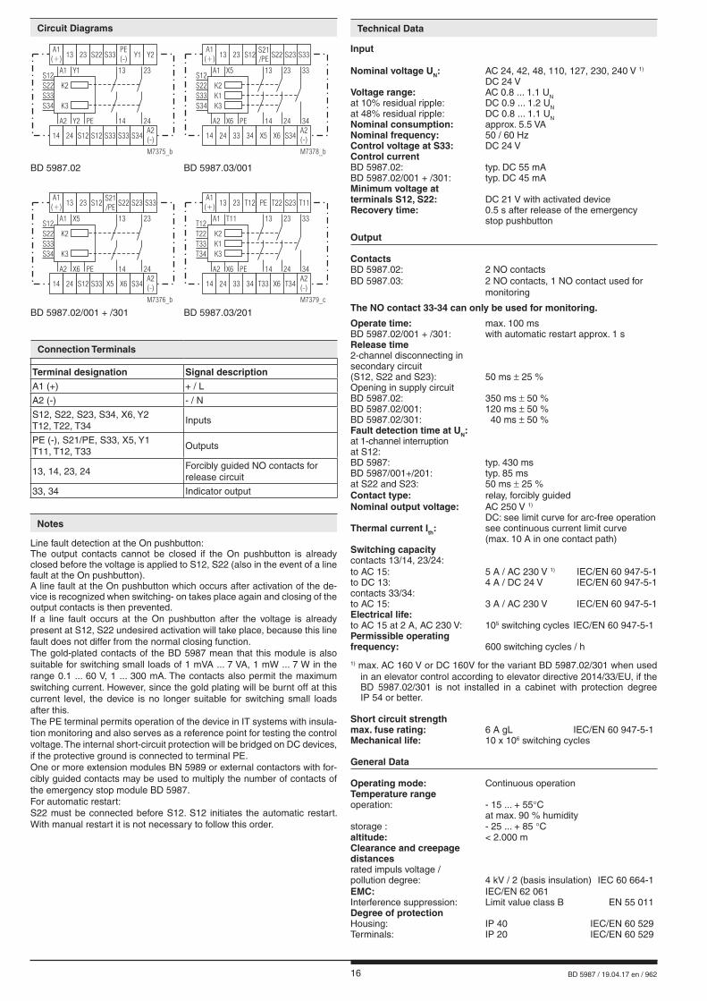
Connection Terminals
Terminal designation Signal descriptionA1 (+) + / L
A2 (-) - / N
S12, S22, S23, S34, X6, Y2 T12, T22, T34
Inputs
PE (-), S21/PE, S33, X5, Y1 T11, T12, T33
Outputs
13, 14, 23, 24Forcibly guided NO contacts for release circuit
33, 34 Indicator output
Notes
Line fault detection at the On pushbutton:The output contacts cannot be closed if the On pushbutton is already closed before the voltage is applied to S12, S22 (also in the event of a line fault at the On pushbutton).A line fault at the On pushbutton which occurs after activation of the de-vice is recognized when switching- on takes place again and closing of the output contacts is then prevented.If a line fault occurs at the On pushbutton after the voltage is already present at S12, S22 undesired activation will take place, because this line fault does not differ from the normal closing function.The gold-plated contacts of the BD 5987 mean that this module is also suitable for switching small loads of 1 mVA ... 7 VA, 1 mW ... 7 W in the range 0.1 ... 60 V, 1 ... 300 mA. The contacts also permit the maximum switching current. However, since the gold plating will be burnt off at this current level, the device is no longer suitable for switching small loads after this.The PE terminal permits operation of the device in IT systems with insula-tion monitoring and also serves as a reference point for testing the control voltage. The internal short-circuit protection will be bridged on DC devices, if the protective ground is connected to terminal PE.One or more extension modules BN 5989 or external contactors with for-cibly guided contacts may be used to multiply the number of contacts of the emergency stop module BD 5987.For automatic restart:S22 must be connected before S12. S12 initiates the automatic restart. With manual restart it is not necessary to follow this order.
Technical DataCircuit Diagrams
K3
K2
Y2 PE
A1 Y1
S33
S12
S22
S34
A2
23
2414
13
S12 S12 S34
S33
S33 S33
A1(+)
PE(-)
S22
14 24
Y113 23 Y2
A2(-)
M7375_b
K3
K2
K1
X6 PE
A1 X5
S33
S12
S22
S34
A2
23
24 34
33
14
13
33 S34
S21/PE
34 X6X5
A1(+)
S22S12
14 24
S2313 23 S33
A2(-)
M7378_b
K3
K2
X6 PE
A1 X5
S33
S12
S22
S34
A2
23
2414
13
S12 S34
S21/PE
S33 X6X5
A1(+)
S22S12
14 24
S2313 23 S33
A2(-)
M7376_b
K3
K2
K1
X6 PE
A1 T11
T33
T12
T22
T34
A2
23
24 34
33
14
13
33 T34
PE
34 X6T33
A1(+)
T22T12
14 24
S2313 23 T11
A2(-)
M7379_c
BD 5987.02 BD 5987.03/001
BD 5987.02/001 + /301 BD 5987.03/201

17 BD 5987 / 19.04.17 en / 962
Housing: Thermoplastic with V0 behaviour according to Ul subject 94Vibration resistance: Amplitude 0,35 mm IEC/EN 60 068-2-6 frequency 10 ... 55 HzClimate resistance: 15 / 055 / 04 IEC/EN 60 068-1Terminal designation: EN 50 005Wire connection: 1 x 4 mm2 solid or 1 x 2,5 mm2 stranded ferruled (isolated) or 2 x 1,5 mm2 stranded ferruled (isolated) DIN 46 228-1/-2/-3/-4 or 2 x 2,5 mm2 stranded ferruled DIN 46 228-1/-2/-3Wire fixing: Plus-minus terminal scews M3.5 box terminal with wire protectionFixing torque: 0.8 NmMounting: DIN rail IEC/EN 60 715Weight: 450 g
Dimensions
Width x height x depth: 45 x 74 x 121 mm
Technical Data
Standard Type
BD 5987.02/001 DC 24 VArticle number: 0040954• Output: 2 NO contacts• Nominal voltage UN: DC 24 V• Width: 45 mm
BD 5987.02/61: with UL approval (Canada/USA)BD 5987.02/001: Optionally cross fault monitoring on the emergency stop loop (see application M6749) Optionally automatic On function when operating voltage is applied or after activation by the On pushbutton.
Jumper asignment for functions:Activation via On pushbutton / or automatic On function:
M8687
On pushbuttonS12-S34 or
S33-S34
JumperX5 - X6
Function
The output contacts are switched only after operation of the On pushbutton. Line fault monitoring at the On push-button.
Automatic On function for operating voltage Off/On or after emergency-stop release
BD 5987.03/001: with 2 NO contacts, 1 signalling contact AC/DC 0,1 ... 1 A / 10 ...120 V
BD 5987.03/201: see BD 5987.03/001, but with special terminal designation
Jumper asignment for functions:Activation via On pushbutton / or automatic On function
M8687
On pushbuttonT11-T34 or
T12-T34
JumperT33 - X6
Function
The output contacts are switched only after operation of the On pushbutton. Line fault monitoring at the On push-button.
Automatic On function for operating voltage Off/On or after emergency-stop release
BD 5987.02/301: Starting behaviour as with BD 5987.02/001, shorter release time when opening the supply circuit, Suitable also for elevators according to EN 81-20/-50, Complies to the requirements of the directive 2014/33/EU for elevators.
Ordering example for variants
BD 5987 .02 /_ _ _ AC 230 V 50/60 Hz
Nominal frequency Nominal voltage Variant, if required Contacts Type
Variants
Troubleshooting
Failure Potential cause
LED "Power" does not light up Power supply not connected
LED "K2" lights up, but "K3" remains off
- Safety relay K2 is welded (replace device) - A 1-channel switch-off occurred on S22, T22 e.g. S23 (switch channel off on S12 e.g. T12)
LED "K3" lights up, but "K2" remains off
- Safety relay K3 is welded (replace device)- A 1-channel switch-off occurred on S12 e.g. T12 (switch channel off on S22, T22 e.g. S23)
Device cannot be activated - Safety relay is welded (replace device) - Manual start mode: Line fault on start-button (disconnect power supply and remove fault) - Automatic start mode: X5 - X6 e.g. T33 - X6 are not bridged
Maintenance and repairs
- The device contains no parts that require maintenance. - In case of failure, do not open the device but send it to manufacturer
for repair.
Nominal voltage UN: AC 24, 42, 48, 110, 127, 230, 240 V DC 24 V
Ambient temperature: - 15 … + 55 °C
Switching capacity: 6 A, 250 Vac G.P.
Wire connection: 60°C / 75°C copper conductors only AWG 18 - 16 Torque 7 lb in
nfoTechnical data that is not stated in the UL-Data, can be found in the technical data section.
UL-Data

18 BD 5987 / 19.04.17 en / 962
Characteristics Application Examples
Two-channel emergeny stop circuit.Suited up to SIL3, Performance Level e, Cat. 4
Single-channel emergency stop circuit. This circuit does not have any red-undancy in the emergency stop control circuit.Suited up to SIL2, Performance Level d, Cat. 3
L1
M6744_aN
emergency-stop
A2(-)
A1(+) S33S34 S33 S33 PE(-) Y2 S12 S12 S22
BD5987
on
Y1
13 23
14 24
L1
M6743_aN
A2(-)
A1(+) S33S34 S33 S33 PE(-) Y2 S12 S12 S22
BD5987
on
off
emergency-stop
Y1
13 23
14 24
L1
M10430_a
A1(+) S12 S12 S22 S21 S23 S33
BD5987.02/301
off
emergency-stop
13 23
N
A2(-) X5S33 X6 S34 14 24
on
00,1 0,3 0,5 1 3 5 10
switching current A
50
100
150
250
200
switc
hing
volta
geVD
C
M29
87_c
safe breaking, no continuous arcing,max. 1 switching cycle / s
Limit curve for arc-free operation with resistive load
1
010
Continuous current limit curve(Current via two contact rows)
20 30 40 50T ( C)�
60
M6759
2
3
4
5
6
7
I (A)
Continouos current limit curve
19 BD 5987 / 19.04.17 en / 962
Application Examples
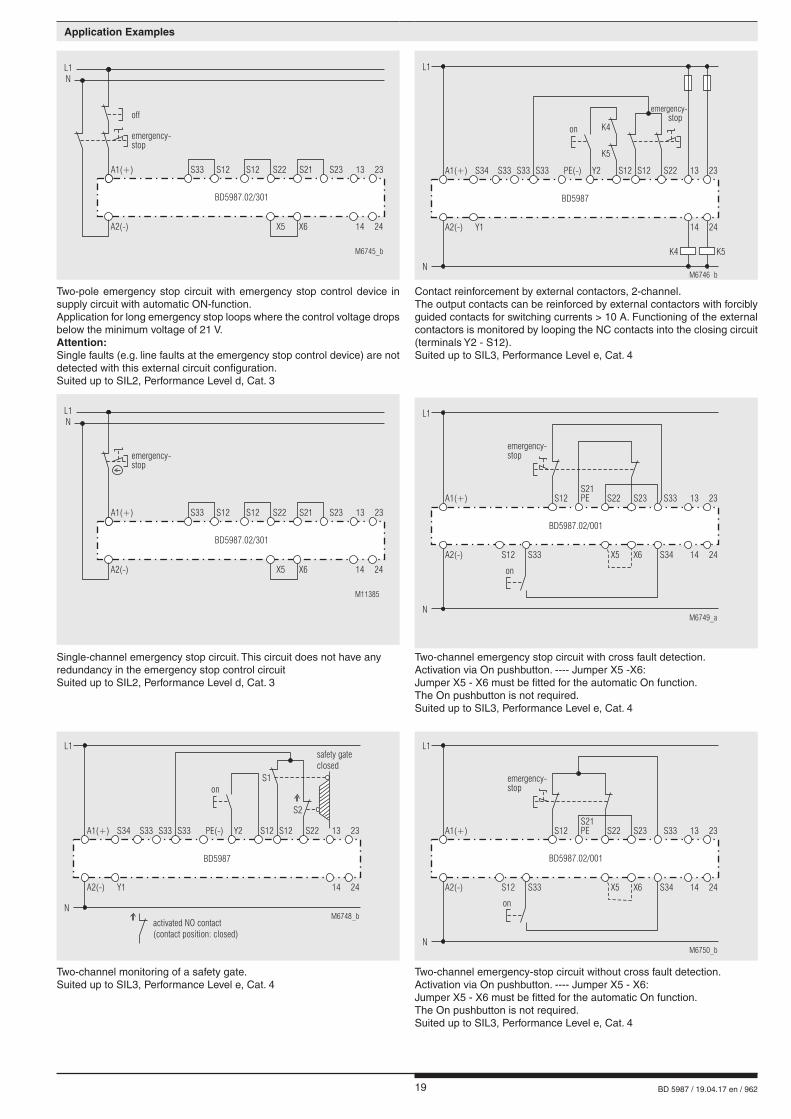
Two-pole emergency stop circuit with emergency stop control device in supply circuit with automatic ON-function.Application for long emergency stop loops where the control voltage drops below the minimum voltage of 21 V.Attention:Single faults (e.g. line faults at the emergency stop control device) are not detected with this external circuit configuration.Suited up to SIL2, Performance Level d, Cat. 3
Contact reinforcement by external contactors, 2-channel.The output contacts can be reinforced by external contactors with forcibly guided contacts for switching currents > 10 A. Functioning of the external contactors is monitored by looping the NC contacts into the closing circuit (terminals Y2 - S12).Suited up to SIL3, Performance Level e, Cat. 4
Single-channel emergency stop circuit. This circuit does not have any redundancy in the emergency stop control circuitSuited up to SIL2, Performance Level d, Cat. 3
Two-channel emergency stop circuit with cross fault detection.Activation via On pushbutton. ---- Jumper X5 -X6:Jumper X5 - X6 must be fitted for the automatic On function.The On pushbutton is not required.Suited up to SIL3, Performance Level e, Cat. 4
Two-channel monitoring of a safety gate.Suited up to SIL3, Performance Level e, Cat. 4
Two-channel emergency-stop circuit without cross fault detection.Activation via On pushbutton. ---- Jumper X5 - X6:Jumper X5 - X6 must be fitted for the automatic On function.The On pushbutton is not required.Suited up to SIL3, Performance Level e, Cat. 4
L1
M6745_b
A1(+)
BD5987.02/301
N
A2(-) X5 X6 14 24
S12 S22S12 S21 S23S33 13 23
off
emergency-stop
L1
M6746_bN
emergency-stop
A2(-)
A1(+) S33S34 S33 S33 PE(-) Y2 S12 S12 S22
Y1
BD5987
13 23
14 24
K4
K5
on
K4 K5
M11385
emergency-stop
L1
A1(+)
BD5987.02/301
N
A2(-) X5 X6 14 24
S12 S22S12 S21 S23S33 13 23
L1
M6749_aN
emergency-stop
A2(-)
A1(+)S21PE S33S23S22S12
X5S33S12 X6 S34
BD5987.02/001
13 23
14 24
on
L1
M6748_bN
A2(-)
A1(+) S33S34 S33 S33 PE(-) Y2 S12 S12 S22
Y1
BD5987
13 23
14 24
onS1
S2
safety gateclosed
activated NO contact(contact position: closed)
L1
M6750_bN
A2(-)
A1(+)S21PE S33S23S22S12
X5S33S12 X6 S34
BD5987.02/001
13 23
14 24
on
emergency-stop

20 BD 5987 / 19.04.17 en / 962
E. DOLD & SÖHNE KG • D-78114 Furtwangene-mail: [email protected] • internet: http://www.dold.com
• PO Box 1251 • Telephone (+49) 77 23 / 654-0 • Telefax (+49) 77 23 / 654-356

21 BD 5987 / 19.04.17 fr / 962
SAFEMASTER Module d'arrêt d'urgence BD 5987
Fiche Technique / Manuel d'utilisation FRANÇAIS
E. DOLD & SÖHNE KGB.P. 1251 • 78114 Furtwangen • AllemagneTél. +49 7723 6540 • Fax +49 7723 [email protected] • www.dold.com
Traduction de la notice originale
0262943

22 BD 5987 / 19.04.17 fr / 962
Tables des matières
Explication des symboles et remarques ..........................................................................................................................23
Remarques ......................................................................................................................................................................23
Usage approprié ..............................................................................................................................................................23
Consignes de sécurité .....................................................................................................................................................23
Description du produit .....................................................................................................................................................25
Diagramme de fonctionnement ........................................................................................................................................25
Schéma-bloc ....................................................................................................................................................................25
Homologations et sigles ..................................................................................................................................................25
Utilisations .......................................................................................................................................................................25
Affichages ........................................................................................................................................................................25
Schémas ..........................................................................................................................................................................26
Borniers ..........................................................................................................................................................................26
Remarques ......................................................................................................................................................................26
Caractéristiques techniques ............................................................................................................................................26
Caractéristiques techniques ............................................................................................................................................27
Versions standard ............................................................................................................................................................27
Diagnostics des défauts ..................................................................................................................................................27
Entretien et remise en état ..............................................................................................................................................27
Variantes ..........................................................................................................................................................................27
Courbes caractéristiques .................................................................................................................................................28
Exemples de raccordement .............................................................................................................................................28
Exemples de raccordement .............................................................................................................................................29
Marquage et raccordements ............................................................................................................................................41
Dimensions (dimensions en mm) ....................................................................................................................................41
Données techniques sécuritaires ....................................................................................................................................42
Déclaration de conformité européenne ...........................................................................................................................43
Déclaration de conformité européenne ...........................................................................................................................44
23 BD 5987 / 19.04.17 fr / 962
Consignes de sécurité
AVERTISSEMENT
Risque d'électrocution ! Danger de mort ou risque de blessure grave.• Assurez-vous que l'installation et l'appareil est et rese en l'état hors tension pendant l'installation électrique.• L'appareil peut uniquement être utilisé dans les cas d'application pré-
vus dans le mode d'emploi / la fiche technique. Les instructions de la documentation correspondante doivent être respectées. Les conditions ambiantes autorisées doivent être respectées.
• La protection de contact des éléments raccordés et l'isolation des câbles d'alimentation doivent être conçus conformément aux prescriptions du mode d'emploi/ fiche technique.
• Respecter les prescriptions de la VDE et les prescriptions locales, et tout particulièrement les mesures de sécurité.
AVERTISSEMENT
Risques d'incendie et autres risques thermiques ! Danger de mort, risque de blessure grave ou dégâts matériels. • L'appareil peut uniquement être utilisé dans les cas d'application prévus
dans le mode d'emploi / la fiche technique. Les instructions de la documen-tation correspondante doivent être respectées. Les conditions ambiantes autorisées doivent être respectées. Respectez tout particulièrement la courbe des seuils de courant.
• L'appareil peut uniquement être installé et mis en service par un personnel dûment qualifié et familier avec la présente documentation technique et avec les prescriptions en vigueur relatives à la sécurité du travail et à la préservation de l'environnement.
AVERTISSEMENT
Erreur de fonctionnement ! Danger de mort, risque de blessure grave ou dégâts matériels. • L'appareil peut uniquement être utilisé dans les cas d'application pré-
vus dans le mode d'emploi / la fiche technique. Les instructions de la documentation correspondante doivent être respectées. Les conditions ambiantes autorisées doivent être respectées.
• L'appareil peut uniquement être installé et mis en service par un personnel dûment qualifié et familier avec la présente documentation technique et avec les prescriptions en vigueur relatives à la sécurité du travail et à la préservation de l'environnement.
• Le relais doit être monté en armoire ayant un indice de protection au moins IP 54 (pas nécessaire pour la variante BD5987.02/301 pour l'utilisation dans une installation d'ascenseur selon directive 2014/33/EU. L'utilisation est limitée à un montage stationaire dans une armoire électrique - pas de montage sur cage d'ascensseur. L'environnement au lieu de montage ne doit pas avoir d'influences négatives sur la fonction du montage. Consultez également l'annotation 1 dans le chapitre "données techniques " et exemples de raccordement M10431_a, M6052_b et M11386); la poussière et l'humidité pouvant entraîner des disfonctionnements.
AVERTISSEMENT
Erreur d'installation ! Danger de mort, risque de blessure grave ou dégâts matériels. • Veillez à protéger suffisamment les contacts de sortie de charges ca-
pacitives et inductives.
! Attention! • La fonction de sécurité doit être activée lors de la mise en service.• S'il apparaît alors que la tension est déjà présente sur S12, S22, on observe une activation involontaire parce que ce court-circuit ne se distingue pas de la fonction d'enclenchement normale.• ATTENTION - Demarrage Automatique ! Selon IEC/EN 60 204-1 Art. 9.2.5.4.2 il est interdit d’effectuer un re- démarrage automatique après un Arrêt d’urgence. Losqu’un démarrage automatique est toutefois demandé, il est necéssaire de assurer qu’une commande prioritaire effectue le blocage après une action d’arrêt d’urgence.• L'ouverture de l'appareil ou des transformations non autorisées annulent la garantie.
DANGER
DANGER: Indique que la mort ou des blessures graves vont survenir en
cas de non respect des précautions demandées.
AVERTISSEMENT
AVERTISSEMENT: Indique que la mort ou des blessures graves peuvent survenir
si les précautions appropriées ne sont pas prises.
PRUDENCE
PRUDENCE: Signifie qu'une blessures légère peut survenir si les précautions
appropriées ne sont pas prises.
! ATTENTION:
Met en garde contre les actions qui peuvent causer des dommages au materiel Software ou hardware suite à un mauvais fonctionne-ment de l'appareil ou de l'environnement de l'appareil.
nfo INFO:
Concerne les informations qui vous sont mises à disposition pour le meilleur usage du produit.
Explication des symboles et remarques
L'installation ne doit être effectuée que par un electricien qualifié
Ne pas jeter aux ordures ménagères! L'appareil doit être éliminé conformément aux prescriptions et
directives nationales en vigueur.
Pour vous aider à comprendre et trouver des passages et des notes de texte spécifiques dans les instructions d'utilisation, nous avons marquées les informations importantes avec des symboles.
Avant l'installation, la mise en service ou l'entretien de cet appareil, on doit avoir lu et compris ce manuel d'utilisation.
Usage approprié
Le produit décrit ici a été développé pour remplir les fonctions de sécurité en tant qu'élément d'une installation globale ou d'une machine. Un systè-me de sécurité complet inclut habituellement des détecteurs ainsi que des modules d'évaluation, de signalisation et de logique aptes à déclencher des coupures de courant sûres. La responsabilité d'assurer la fiabilité de l'ensemble de la fonction incombe au fabricant de l'installation ou de la ma-chine. DOLD n'est pas en mesure de garantir toutes les caractéristiques d'une installation ou d'une machine dont la conception lui échappe. C'est à l'utilisateur de valider la conception globale du système auquel ce relais est connecté. DOLD ne prend en charge aucune responsabilité quant aux recommandations qui sont données ou impliquées par la description sui-vante. Sur la base du présent manuel d'utilisation, on ne pourra déduire aucune modification concernant les conditions générales de livraison de DOLD, les exigences de garantie ou de responsabilité.
Remarques
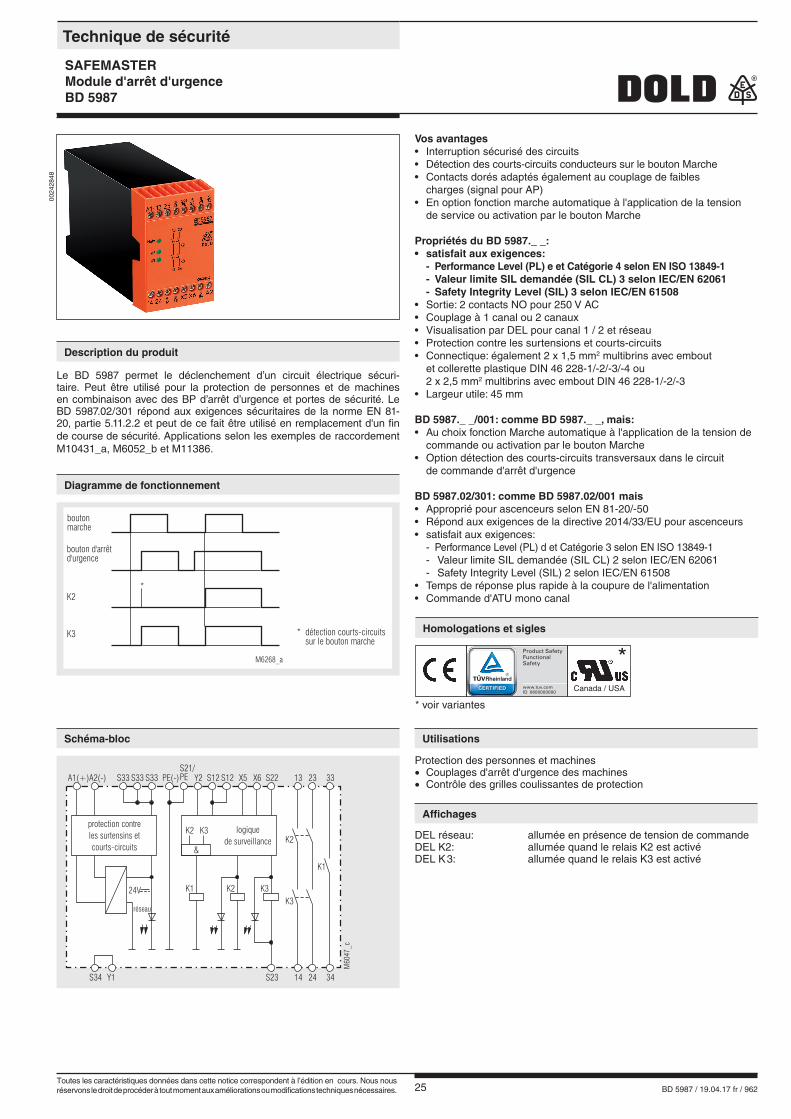
Le BD 5987 permet le déclenchement d’un circuit électrique sécuri-taire. Peut être utilisé pour la protection de personnes et de machines en combinaison avec des BP d’arrêt d’urgence et portes de sécurité. Le BD 5987.02/301 répond aux exigences sécuritaires de la norme EN 81-20, partie 5.11.2.2 et peut de ce fait être utilisé en remplacementd'un fin de course de sécurité. Applications selon les exemples de raccordement M10431_a, M6052_b et M11386.En cas d'emploi approprié et d'observation de ces instructions, on ne connaît aucun risque résiduel. Dans le cas contraire, on encourt des riques de dommages corporels et matériels.
Stockage pour référence future

24 BD 5987 / 19.04.17 fr / 962
25 BD 5987 / 19.04.17 fr / 962
Vos avantages• Interruption sécurisé des circuits• Détection des courts-circuits conducteurs sur le bouton Marche• Contacts dorés adaptés également au couplage de faibles charges (signal pour AP)• En option fonction marche automatique à l'application de la tension de service ou activation par le bouton Marche
Propriétés du BD 5987._ _:• satisfait aux exigences: - Performance Level (PL) e et Catégorie 4 selon EN ISO 13849-1 - Valeur limite SIL demandée (SIL CL) 3 selon IEC/EN 62061 - Safety Integrity Level (SIL) 3 selon IEC/EN 61508• Sortie: 2 contacts NO pour 250 V AC• Couplage à 1 canal ou 2 canaux• Visualisation par DEL pour canal 1 / 2 et réseau• Protection contre les surtensions et courts-circuits• Connectique: également 2 x 1,5 mm2 multibrins avec embout et collerette plastique DIN 46 228-1/-2/-3/-4 ou 2 x 2,5 mm2 multibrins avec embout DIN 46 228-1/-2/-3• Largeur utile: 45 mm BD 5987._ _/001: comme BD 5987._ _, mais:• Au choix fonction Marche automatique à l'application de la tension de commande ou activation par le bouton Marche• Option détection des courts-circuits transversaux dans le circuit de commande d'arrêt d'urgence BD 5987.02/301: comme BD 5987.02/001 mais• Approprié pour ascenceurs selon EN 81-20/-50• Répond aux exigences de la directive 2014/33/EU pour ascenceurs• satisfait aux exigences: - Performance Level (PL) d et Catégorie 3 selon EN ISO 13849-1
- Valeur limite SIL demandée (SIL CL) 2 selon IEC/EN 62061 - Safety Integrity Level (SIL) 2 selon IEC/EN 61508
• Temps de réponse plus rapide à la coupure de l'alimentation• Commande d'ATU mono canal
0024
2848
boutonmarche
K2
M6268_a
K3 * détection courts-circuitssur le bouton marche
*
bouton d'arrêtd'urgence
M60
47_c
A1(+)A2(-) S33 PE(-)S33S33 Y2 S12 S12S21/PE S22X6X5 332313
S34 Y1 34S23 2414
K2K1K3
K1
K3
K2 K3
&
réseau
24V
protection contreles surtensins etcourts-circuits
logiquede surveillance K2
Protection des personnes et machines• Couplages d'arrêt d'urgence des machines• Contrôle des grilles coulissantes de protection
DEL réseau: allumée en présence de tension de commandeDEL K2: allumée quand le relais K2 est activéDEL K 3: allumée quand le relais K3 est activé
Technique de sécurité
SAFEMASTERModule d'arrêt d'urgenceBD 5987
* voir variantes
Canada / USA
*
Description du produit
Diagramme de fonctionnement
Utilisations
Affichages
Homologations et sigles
Le BD 5987 permet le déclenchement d’un circuit électrique sécuri-taire. Peut être utilisé pour la protection de personnes et de machines en combinaison avec des BP d’arrêt d’urgence et portes de sécurité. Le BD 5987.02/301 répond aux exigences sécuritaires de la norme EN 81-20, partie 5.11.2.2 et peut de ce fait être utilisé en remplacement d'un fin de course de sécurité. Applications selon les exemples de raccordement M10431_a, M6052_b et M11386.
Schéma-bloc
Toutes les caractéristiques données dans cette notice correspondent à l’édition en cours. Nous nous réservons le droit de procéder à tout moment aux améliorations ou modifications techniques nécessaires.
26 BD 5987 / 19.04.17 fr / 962
Détection des courts-circuits conducteurs sur le bouton Marche:Si le bouton Marche est déjà fermé avant l'application de la tension sur S12, S22 (même en cas de court-circuit sur le bouton Marche), les con-tacts de sortie ne se laissent pas enclencher.Un court-circuit conducteur sur le bouton Marche survenant après l'activation du module est détecté lors de l'opération d'enclenchement sui-vante, et l'enclenchement des contacts de sortie est empêché. S'il apparaît alors que la tension est déjà présente sur S12, S22, on ob-serve une activation involontaire parce que ce court-circuit ne se distingue pas de la fonction d'enclenchement normale.Par ses contacts dorés, le module BD 5987 convient également au cou-plage de faibles charges 1 mVA ... 7 VA, 1 mW ... 7 W dans la plage de 0,1 ... 60 V, 1 ... 300 mA. Les contacts laissent également passer le maximum de charge, mais dans ce cas le revêtement est détruit et ne permet pas de réutiliser l'appareil pour de faibles charges.La borne de raccordement PE permet d'utiliser l'appareil dans des ré-seaux IT avec contrôle d'isolement ou de l'employer comme point de réfé-rence pour le contrôle de la tension de commande. Sur les modules DC, le branchement du conducteur de protection sur la borne de raccordement PE a pour effet de shunter la protection interne contre les courts-circuits.Pour la multiplication des contacts du module d'arrêt d'urgence BD 5987, on peut utiliser un ou plusieurs modules d'extension BN 3081 ou des con-tacteurs externes à contacts liés.Attention : en démarrage automatique, S22 doit être fermé avant S12, car S12 engage le démarrage automatique.En fonction démarrage, l'ordre d'enclenchement n'a aucune importance.
Entrée
Tension assignée UN: 24, 42, 48, 110, 127, 230, 240 V AC 1)
24 V DCPlage de tensions: AC 0,8 ... 1,1 UNà 10% d'ondulation résid.: DC 0,9 ... 1,2 UNà 48% d'ondulatin résid.: DC 0,8 ... 1,1 UNConsommation nominale: env. 5,5 VAFréquence assignée: 50 / 60 HzTens. de cde sur S33: 24 V DCCourant de commandeBD 5987.02: réf. DC 55 mABD 5987.02/001 + /301: réf. DC 45 mATension minimalesur les bornes S12, S22: 21 V DC, appareil activéTemps de rémarmement: 0,5 s après déverrouillage du bouton d'arrêt d'urgence
Sortie
Garnissage en contacts BD 5987.02: 2 contacts NOBD 5987.03: 2 contacts NO, 1 contacts NO utilisables uniquement comme contacts de signalisation
Le contact à fermeture 33-34 sont utilisables uniquement comme contacts de signalisation.
Temps de réponse: max. 100 msBD 5987.02/001 + /301: en démarrage automatique: env. 1 sTemps de retombée:Déconnexion 2 canaux dans lecicruit secondaire (S12, S22 et S23): 50 ms ± 25 % en cas de coupure dans le circuit réseauBD 5987.02: 350 ms ± 50 %BD 5987.02/001: 120 ms ± 50 %BD 5987.02/301: 40 ms ± 50 %Temps de détection à UN:avec une interruption monocanal à S12:BD 5987: typ. 430 msBD 5987/001+/201: typ. 85 msà S22 and S23: 50 ms ± 25 %Nature des contacts: relais liésTension nominale de sortie: 250 V AC 1)
DC: voir courbe limite d'arcCourant thermique Ith: voir courbe limite de courant continu (max. 10 A dans une connexion de contact)Pouvoir de coupurecontact 13/14, 23/24:en AC 15: 5 A / 230 V AC 1) IEC/EN 60 947-5-1en DC 13: 4 A / 24 V DC IEC/EN 60 947-5-1contact 33/34:en AC 15: 3 A /230 V AC IEC/EN 60 947-5-1Longévité électrique:en AC 15 pour 2 A, 230 V AC: 105 manoeuvres IEC/EN 60947-5-1Cadence admissible: 600 manoeuvres / h
1) max. 160 V AC ou max. 160 V DC pour la variante BD 5987.02/301 pour l'utilisation dans une installation d'ascenseur selon directive pour ascenseurs 2014/33/EU, si le BD 5987.02/301 n'est pas monté en une armoire de classe de protection IP 54 ou supérieure.Tenue aux courts-circuits,calibre max. de fusible: 6 A gL IEC/EN 60947-5-1Longévité mécanique: 10 x 106 manoeuvres
Caractéristiques générales
Type nominal de service: service permanentPlage de températuresopération: - 15 ... + 55 °C stockage: - 25 ... + 85 °C Altitude: < 2.000 m pour 90% max. d'humidité atmosphériqueDistances dans l'airet lignes de fuiteCatégorie de surtension /degré de contamination: 4 kV / 2 (isolation de base) IEC 60 664-1CEM IEC/EN 62 061Antiparasitage: seuil classe B EN 55 011Degré de protectionboîtier: IP 40 IEC/EN 60 529bornes: IP 20 IEC/EN 60 529
K3
K2
X6 PE
A1 X5
S33
S12
S22
S34
A2
23
2414
13
S12 S34
S21/PE
S33 X6X5
A1(+)
S22S12
14 24
S2313 23 S33
A2(-)
M7376_b
K3
K2
K1
X6 PE
A1 X5
S33
S12
S22
S34
A2
23
24 34
33
14
13
33 S34
S21/PE
34 X6X5
A1(+)
S22S12
14 24
S2313 23 S33
A2(-)
M7378_b
BD 5987.03/001
K3
K2
Y2 PE
A1 Y1
S33
S12
S22
S34
A2
23
2414
13
S12 S12 S34
S33
S33 S33
A1(+)
PE(-)
S22
14 24
Y113 23 Y2
A2(-)
M7375_b
BD 5987.02/001 + /301
BD 5987.02
K3
K2
K1
X6 PE
A1 T11
T33
T12
T22
T34
A2
23
24 34
33
14
13
33 T34
PE
34 X6T33
A1(+)
T22T12
14 24
S2313 23 T11
A2(-)
M7379_c
BD 5987.03/201
Borniers
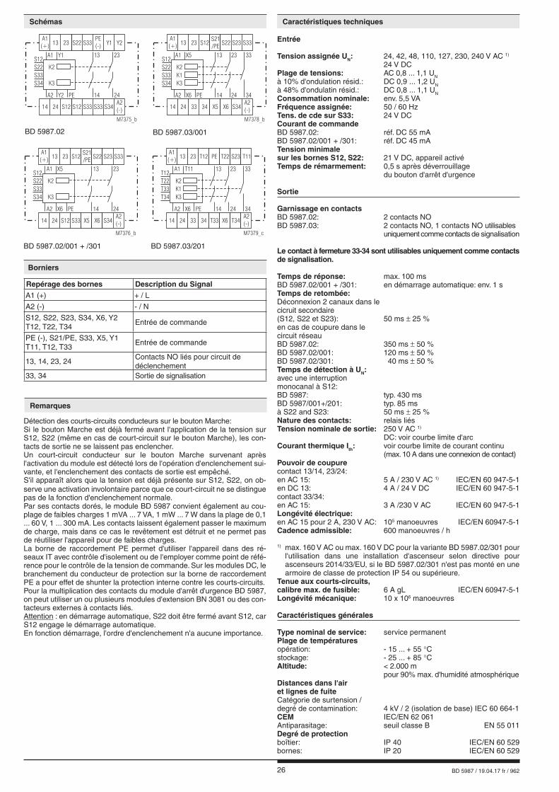
Repérage des bornes Description du SignalA1 (+) + / L
A2 (-) - / N
S12, S22, S23, S34, X6, Y2 T12, T22, T34
Entrée de commande
PE (-), S21/PE, S33, X5, Y1 T11, T12, T33
Entrée de commande
13, 14, 23, 24Contacts NO liés pour circuit de déclenchement
33, 34 Sortie de signalisation
Schémas
Remarques
Caractéristiques techniques
27 BD 5987 / 19.04.17 fr / 962
Boîtier: thermoplastique à comportement V0 selon UL Subj. 94Résistance aux vibrations: amplitude 0,35 mm fréquence 10 ... 55 Hz, IEC/EN 60 068-2-6Résistance climatique: 15 / 055 / 04 IEC/EN 60 068-1Repérage des bornes: EN 50 005Connectique: 1 x 4 mm2 massif ou 1 x 2,5 mm2 multibrins avec embout et collerette plastique, ou 2 x 1,5 mm2 multibrins avec embout et collerette plastique DIN 46 228-1/-2/-3/-4 ou 2 x 2,5 mm2 multibrins avec embout DIN 46 228-1/-2/-3Fixation des conducteurs: vis de serrage cruciforme M3,5 borne caisson av. protection conducteurCouple de serrage: 0,8 NmFixation instantanée: sur rail IEC/EN 60 715Poids net: 450 g
Dimensions
Largeur x hauteur x prof.: 45 x 74 x 121 mm
BD 5987.02/001 24 V DCRéférence: 0040954• Sortie: 2 contacts NO• Tension assignée UN: 24 V DC• Largeur utile: 45 mm
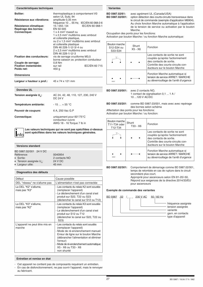
BD 5987.02/61: avec agrément UL (Canada/USA)BD 5987.02/001: option détection des courts-circuits transversaux dans le circuit de commande (exemple d'application M6904). Au choix fonction Marche automatique à l'application de la tension de service ou activation par le bouton Marche.Occupation des ponts pour les fonctions:Activation par bouton Marche / ou fonction Marche automatique:
M8687
BD 5987.03/001: avec 2 contacts NO, 1 contact de signalisation 0,1 ... 1 A / 10 ...120 V AC/DC
BD 5987.03/201: comme BD 5987.03/001, mais avec avec repérage des bornes selon schémaAffectation des ponts pour les fonctions:Activation par bouton Marche / ou fonction:
M8687
Bouton marcheT11-T34 oder
T12-T34
ShuntT33 - X6
Fonction
Les contacts de sortie ne sont couplés qu'après l'actionnementdes contacts de sortie.Contrôle des courts-circuits con-ducteurs sur le bouton Marche
Fonction Marche automatique si tension de service ARRET / MARCHEau déverrouillage de l'arrêt d'urgence
BD 5987.02/301: Comportement de démarrage comme BD 5987.02/001, temps de retombée en cas de rupture dans le circuit secondaire plus court, Approprié pour ascenceurs selon EN 81-20/-50, Répond aux exigences de la directive 2014/33/EU pour ascenceurs
Exemple de commande des variantes
BD 5987 .02 /_ _ _ 230 V AC 50 / 60 Hz fréquence assignée tension assignée variante garn. en contacts type d'appareil
Caractéristiques techniques
Versions standard
Variantes
Bouton marcheS12-S34 ou
S33-S34
ShuntX5 - X6
Fonction
Les contacts de sortie ne sont couplés qu'après l'actionnementdes contacts de sortie.Contrôle des courts-circuits con-ducteurs sur le bouton Marche
Fonction Marche automatique si tension de service ARRET / MARCHEau déverrouillage de l'arrêt d'urgence
Diagnostics des défauts
Défaut Cause possible
DEL "réseau" ne s'allume pas L'alimentation n'est pas connectée
La DEL "K2" s'allume,mais pas "K3"
- Les contacts du relais K2 sont soudés (remplacer l'appareil) - Le déclenchement d'un canal s'est produit sur S22, T22 ou S23 (déclencher le canal sur S12 ou T12)
La DEL "K3" s'allume,mais pas "K2"
- Les contacts du relais K3 sont soudés (remplacer l'appareil) - Le déclenchement d'un canal s'est produit sur S12 ou T12 (déclencher le canal sur S22, T22 ou S23)
L'appareil ne peut être mis en marche
- Les contacts du relais sont soudés (remplacer l'appareil) - Mode de ré-enclenchement manuel: Erreur de ligne sur le bouton Marche (débrancher l'alimentation et éliminer l'erreur) - Mode de ré-enclenchement automatique: X5 - X6 ou T33 - X6 non shunté
Entretien et remise en état
- Cet appareil ne contient pas de composants requérant un entretien. - En cas de disfonctionnement, ne pas ouvrir l'appareil, mais le renvoyer
au fabricant.
Tension assignée UN: AC 24, 42, 48, 110, 127, 230, 240 V DC 24 V
Température ambiante: - 15 … + 55 °C
Pouvoir de coupure: 6 A, 250 Vac G.P Connectique: uniquement pour 60°/75°C conducteur cuivre AWG 18 - 16 Torque 7 lb in
nfoLes valeurs techniques qui ne sont pas spécifiées ci-dessus sont spécifiées dans les valeurs techniques générales.
Données UL
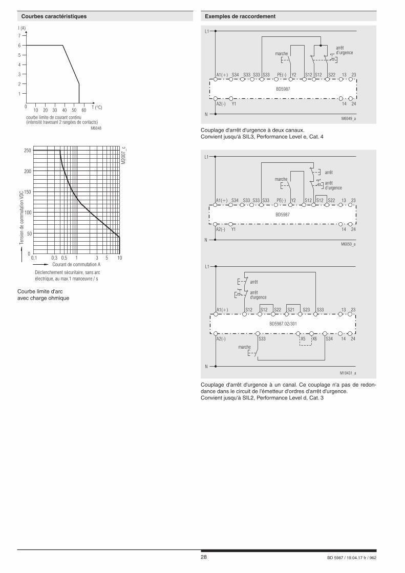
28 BD 5987 / 19.04.17 fr / 962
Couplage d'arrêt d'urgence à deux canaux.Convient jusqu‘à SIL3, Performance Level e, Cat. 4
Couplage d'arrêt d'urgence à un canal. Ce couplage n'a pas de redon-dance dans le circuit de l'émetteur d'ordres d'arrêt d'urgence.Convient jusqu‘à SIL2, Performance Level d, Cat. 3
Courbe limite d'arc avec charge ohmique
1
010
courbe limite de courant continu(intensité travesant 2 rangées de contacts)
20 30 40 50T ( C)�
60
M6048
2
3
4
5
6
7
I (A)L1
M6049_aN
arrêtd’urgence
A2(-)
A1(+) S33S34 S33 S33 PE(-) Y2 S12 S12 S22
BD5987
marche
Y1
13 23
14 24
L1
M6050_aN
A2(-)
A1(+) S33S34 S33 S33 PE(-) Y2 S12 S12 S22
BD5987
arrêt
arrêtd’urgence
marche
Y1
13 23
14 24
L1
M10431_a
A1(+)
BD5987.02/301
arrêt
arrêtd'urgence
N
A2(-) X5S33 X6 S34 14 24
marche
S12 S12 S22 S21 S23 S33 13 23
Courbes caractéristiques Exemples de raccordement
00,1 0,3 0,5 1 3 5 10
Courant de commutation A
50
100
150
250
200
M20
07_c
Déclenchement sécuritaire, sans arcélectrique, au max.1 manoeuvre / s
Tens
ion
deco
mm
u tat
i on
VDC
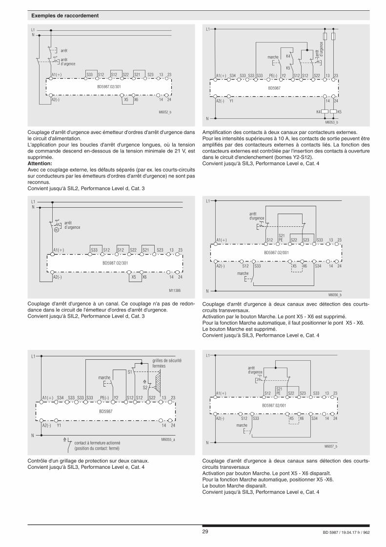
29 BD 5987 / 19.04.17 fr / 962
Couplage d'arrêt d'urgence à deux canaux avec détection des courts-crcuits transversaux.Activation par le bouton Marche. Le pont X5 - X6 est supprimé.Pour la fonction Marche automatique, il faut positionner le pont X5 - X6.Le bouton Marche est supprimé.Convient jusqu‘à SIL3, Performance Level e, Cat. 4
Amplification des contacts à deux canaux par contacteurs externes.Pour les intensités supérieures à 10 A, les contacts de sortie peuvent être amplifiés par des contacteurs externes à contacts liés. La fonction des contacteurs externes est contrôlée par l'insertion des contacts à ouverture dans le circuit d'enclenchement (bornes Y2-S12).Convient jusqu‘à SIL3, Performance Level e, Cat. 4
Couplage d'arrêt d'urgence à un canal. Ce couplage n'a pas de redon-dance dans le circuit de l'émetteur d'ordres d'arrêt d'urgence.Convient jusqu‘à SIL2, Performance Level d, Cat. 3
Contrôle d'un grillage de protection sur deux canaux.Convient jusqu‘à SIL3, Performance Level e, Cat. 4
Couplage d'arrêt d'urgence à deux canaux sans détection des courts-circuits transversauxActivation par bouton Marche. Le pont X5 - X6 disparaît.Pour la fonction Marche automatique, positionner X5 -X6. Le bouton Marche disparaît.Convient jusqu‘à SIL3, Performance Level e, Cat. 4
L1
M6053_bN
arrê
td’
urge
nce
A2(-)
A1(+) S33S34 S33 S33 PE(-) Y2 S12 S12 S22
Y1
BD5987
13 23
14 24
K4
K5
K4 K5
marche
L1
M6055_aN
A2(-)
A1(+) S33S34 S33 S33 PE(-) Y2 S12 S12 S22
Y1
BD5987
13 23
14 24
contact à fermeture actionné(position du contact: fermé)
S1
S2
grilles de sécuritéfermées
marche
L1
M6057_bN
A2(-)
A1(+)S21PE S33S23S22S12
X5S33S12 X6 S34
BD5987.02/001
13 23
14 24
arrêtd'urgence
marche
L1
M6056_bN
A2(-)
A1(+)S21PE S33S23S22S12
X5S33S12 X6 S34
BD5987.02/001
13 23
14 24
arrêtd'urgence
marche
Couplage d'arrêt d'urgence avec émetteur d'ordres d'arrêt d'urgence dans le circuit d'alimentation.L'application pour les boucles d'arrêt d'urgence longues, où la tension de commande descend en-dessous de la tension minimale de 21 V, est supprimée.Attention:Avec ce couplage externe, les défauts séparés (par ex. les courts-circuits sur conducteurs par les émetteurs d'ordres d'arrêt d'urgence) ne sont pas reconnus.Convient jusqu‘à SIL2, Performance Level d, Cat. 3
M6052_b
arrêt
arrêtd’urgence
L1
A1(+)
BD5987.02/301
N
A2(-) X5 X6 14 24
S12 S22S12 S21 S23S33 13 23
M11386
arrêtd’urgence
L1
A1(+)
BD5987.02/301
N
A2(-) X5 X6 14 24
S12 S22S12 S21 S23S33 13 23
Exemples de raccordement

30 BD 5987 / 19.04.17 fr / 962
E. DOLD & SÖHNE KG • D-78114 Furtwangene-mail: [email protected] • internet: http://www.dold.com
• B.P. 1251 • Téléphone (+49) 77 23 / 654-0 • Téléfax (+49) 77 23 / 654-356

31 BD 5987 / 19.04.17 it / 962
SAFEMASTER Modulo Stop Emergenza BD 5987
Scheda tecnica / Istruzioni operative ITALIANO
E. DOLD & SÖHNE KGPostfach 1251 • 78114 Furtwangen • DeutschlandTelefon +49 7723 6540 • Fax +49 7723 [email protected] • www.dold.com
Traduzione delle istruzioni originali
0262943
32 BD 5987 / 19.04.17 it / 962
Contenuto
Simboli e Annotazioni ......................................................................................................................................................33
Note generali ...................................................................................................................................................................33
Destinazione d'uso ..........................................................................................................................................................33
Avvertenze di sicurezza ...................................................................................................................................................33
Descrizione del prodotto ..................................................................................................................................................35
Diagramma funzionale .....................................................................................................................................................35
Schema a blocchi ............................................................................................................................................................35
Approvazioni e marchi ....................................................................................................................................................35
Applicazioni .....................................................................................................................................................................35
Indicazioni ........................................................................................................................................................................35
Schemi circuitali ...............................................................................................................................................................36
Connessione morsetti ......................................................................................................................................................36
Nota .................................................................................................................................................................................36
Caratteristiche tecniche ...................................................................................................................................................36
Caratteristiche tecniche ...................................................................................................................................................37
Procedere quando i disturbi .............................................................................................................................................37
Manutenzione e riparazione ............................................................................................................................................37
Tipo standard ...................................................................................................................................................................37
Varianti .............................................................................................................................................................................37
Curve caratteristiche........................................................................................................................................................38
Esempi applicativi ............................................................................................................................................................38
Esempi applicativi ............................................................................................................................................................39
Marcatura e collegamenti ................................................................................................................................................41
Dimensioni (dimensione in mm) ......................................................................................................................................41
I dati di sicurezza .............................................................................................................................................................42
Dichiarazione di conformità CE .......................................................................................................................................43
Dichiarazione di conformità CE .......................................................................................................................................44
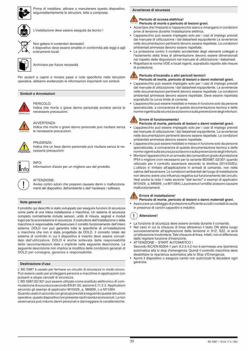
33 BD 5987 / 19.04.17 it / 962
Avvertenze di sicurezza
AVVERTENZA
Pericolo di scossa elettrica! Pericolo di morte o pericolo di lesioni gravi. • Accertare che l'impianto e l'apparecchio siano e rimangano in condizioni prive di tensione durante l'installazione elettrica.• L'apparecchio può essere impiegato solo per i casi di impiego previsti
dal manuale di utilizzazione / dal datasheet equipollente Le avvertenze nelle documentazioni pertinenti devono essere rispettate. Le condizioni ambientali ammesse devono essere rispettate.
• La protezione contro il contatto accidentale degli elementi collegati e l'isolamento della linea di alimentazione devono essere dimensionati nel rispetto delle disposizioni nel manuale di utilizzazione / datasheet.
• Rispettare le norme VDE e locali vigenti, soprattutto rispetto alle misure di protezione.
AVVERTENZA
Pericolo d'incendio o altri pericoli termici! Pericolo di morte, pericolo di lesioni o danni materiali gravi. • L'apparecchio può essere impiegato solo per i casi di impiego previsti
dal manuale di utilizzazione / dal datasheet equipollente. Le avvertenze nelle documentazioni pertinenti devono essere rispettate. Le condizioni ambientali ammesse devono essere rispettate. Deve essere rispettata soprattutto la curva limite di corrente.
• L'apparecchio può essere installato e messo in funzione solo da persone specializzate, a conoscenza di questa documentazione tecnica e delle norme vigenti sulla sicurezza sul lavoro e sulla prevenzione degli infortuni.
AVVERTENZA
Errore di funzionamento! Pericolo di morte, pericolo di lesioni o danni materiali gravi. • L'apparecchio può essere impiegato solo per i casi di impiego previsti
dal manuale di utilizzazione / dal datasheet equipollente. Le avvertenze nelle documentazioni pertinenti devono essere rispettate. Le condizioni ambientali ammesse devono essere rispettate.
• L'apparecchio può essere installato e messo in funzione solo da persone specializzate, a conoscenza di questa documentazione tecnica e delle norme vigenti sulla sicurezza sul lavoro e sulla prevenzione degli infortuni.
• Montare l'apparecchio in un armadio dei comandicon grado di protezione IP54 o migliore (non necessario per la variante BD5987.02/301 quando utilizzato per il controllo ascensore secondo la direttiva 2014/33/EU. L'utilizzo e' limitato all'applicazione in armadi di comando, non nella cabina dell'ascensore. Le condizioni ambientali del luogo di installazione non devono avere una influenza negativa sul funzionamento del circuito. Vedi anche la nota 1 nella sezione "dati tecnici" e esempi di applicativi M10429_a, M6899_c e M11384). La polvere e l'umidita' possono causare malfunzionamenti.
AVVERTENZA
Errore di installazione! Pericolo di morte, pericolo di lesioni o danni materiali gravi. • Assicurare un cablaggio di protezione sufficiente su tutti i contatti di uscita
in presenza di carichi capacitivi e induttivi.
! Attenzione! • La funzione di sicurezza deve essere avviata durante il comando.• Nel caso in cui la chiusura di linea attraverso il tasto ON abbia luogo successivamente all'applicazione della tensione in S12, S22, si avrà un'attivazione involontaria. Tale chiusura di linea, infatti, non si differenzia dalla regolare funzione d'inserzione.• ATTENZIONE – START AUTOMATICO ! Secondo IEC/EN 60204-1 part. 9.2.5.4.2 non è permessa una ripartenza automatica alla lo stop d’emergenza. Quindi il controllo macchina deve disabilitare la ripartenza automatica alla lo Stop d’Emergenza.• Aprire il dispositivo o eseguire cambi non autorizzati fa decadere ogni garanzia.
PERICOLO
PERICOLO: Indica che morte o grave danno personale avviene senza le
necessarie precauzioni.
AVVERTENZA
AVVERTENZA: Indica che morte o grave danno personale può risultare senza
le necessarie precauzioni.
PRUDENZA: Indica che un lieve danno personale può risultare senza le ne-
cessarie precauzioni.
! ATTENZIONE:
Avviso contro azioni che possono causare danni o malfunziona-menti del dispositivo, dell'ambiente o dell' hardware / software.
nfo INFO:
Informazioni d'aiuto per un migliore uso del prodotto.
Il prodotto qui descritto è stato sviluppato per eseguire funzioni di sicurezza come parte di una intera installazione o macchina. Un sistema di sicurezza completo normalmente include sensori, unità di misura, segnali e moduli logici per la sconnessione in sicurezza. Il costruttore dell’installazione o della macchina è responsabile nell’assicurare il corretto funzionamento dell’intero sistema. DOLD non può garantire tutte le specifiche di un’installazione o macchina che non è stata progettata da DOLD. Il concetto totale del sistema di controllo in cui il dispositivo è inserito deve essere convali-dato dall’utilizzatore. DOLD è anche sollevata dalla responsabilità delle raccomandazioni date o implicite nelle seguente descrizione. La seguente descrizione non implica la modifica delle condizioni generali di DOLD per consegna, garanzia e responsabilità.
Note generali
Simboli e Annotazioni
Destinazione d'uso
L' BD 5987 è ussato per fermare un circuito di sicurezza in modo sicuro. Può essere usato per proteggere persone e macchine in applicazioni con pulsanti e-stope cancelli di sicurezza. L' BD 5987.02/301 può essere utilizato come sostituto elettronico di com-mutatzione di sucurezza secondo EN 81-20, sezione 5.11.2.2. Applicationi secondo gli esempi di applicativi M10429_a, M6899_c e M11384.Quando usato in accordo con gli scopi previsti e seguendo queste istruzioni operative, questo dispositivo non presenta rischi residui sconosciuti. La non osservanza può indurre danni personali e danneggiare le caratteristiche.
L'installazione deve essere eseguita da tecnici !
Non gettare in contenitori domestici! Il dispositivo deve essere smaltito in conformità alle leggi e agli ordinamenti locali.
Archiviare per future necessità
Per aiutarti a capire e trovare passi e note specifiche nelle istruzioni operative, abbiamo evidenziato le informazioni importanti con simboli.
Prima di installare, attivare o manutenere questo dispositivo, seguireattentamente le istruzioni, lette e comprese.

34 BD 5987 / 19.04.17 it / 962
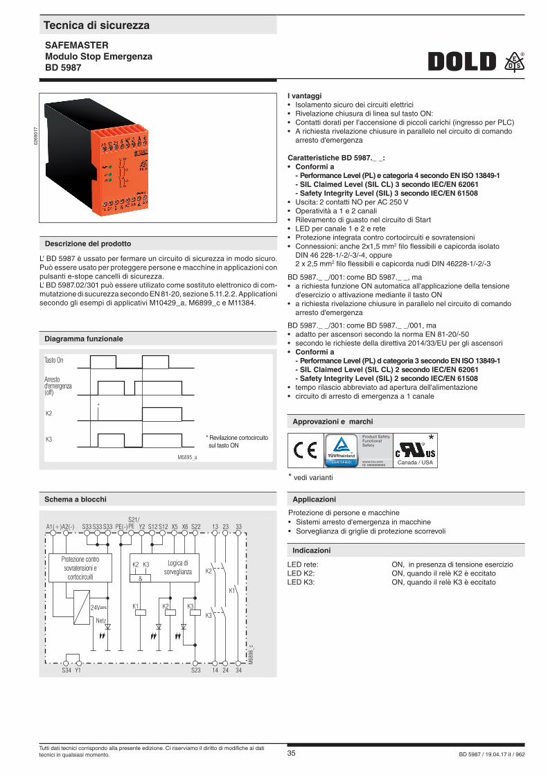
35 BD 5987 / 19.04.17 it / 962
I vantaggi• Isolamento sicuro dei circuiti elettrici• Rivelazione chiusura di linea sul tasto ON:• Contatti dorati per I'accensione di piccoli carichi (ingresso per PLC)• A richiesta rivelazione chiusure in parallelo nel circuito di comando arresto d'emergenza
Caratteristiche BD 5987._ _: • Conformi a
- Performance Level (PL) e categoria 4 secondo EN ISO 13849-1 - SIL Claimed Level (SIL CL) 3 secondo IEC/EN 62061 - Safety Integrity Level (SIL) 3 secondo IEC/EN 61508
• Uscita: 2 contatti NO per AC 250 V• Operatività a 1 e 2 canali• Rilevamento di guasto nel circuito di Start• LED per canale 1 e 2 e rete• Protezione integrata contro cortocircuiti e sovratensioni• Connessioni: anche 2x1,5 mm2 filo flessibili e capicorda isolato
DIN 46 228-1/-2/-3/-4, oppure 2 x 2,5 mm2 filo flessibili e capicorda nudi DIN 46228-1/-2/-3
BD 5987._ _/001: come BD 5987._ _, ma• a richiesta funzione ON automatica all'applicazione della tensione
d'esercizio o attivazione mediante il tasto ON• a richiesta rivelazione chiusure in parallelo nel circuito di comando
arresto d'emergenza
BD 5987._ _/301: come BD 5987._ _/001, ma• adatto per ascensori secondo la norma EN 81-20/-50• secondo le richieste della direttiva 2014/33/EU per gli ascensori• Conformi a
- Performance Level (PL) d categoria 3 secondo EN ISO 13849-1 - SIL Claimed Level (SIL CL) 2 secondo IEC/EN 62061 - Safety Integrity Level (SIL) 2 secondo IEC/EN 61508
• tempo rilascio abbreviato ad apertura dell'alimentazione• circuito di arresto di emergenza a 1 canale
026
9017
Protezione di persone e macchine• Sistemi arresto d'emergenza in macchine• Sorveglianza di griglie di protezione scorrevoli
LED rete: ON, in presenza di tensione esercizio LED K2: ON, quando il relè K2 è eccitatoLED K3: ON, quando il relè K3 è eccitato
* vedi varianti
Canada / USA
*
Tecnica di sicurezza
SAFEMASTERModulo Stop Emergenza BD 5987
Diagramma funzionale
Schema a blocchi
Approvazioni e marchi
Applicazioni
Indicazioni
Descrizione del prodotto
L' BD 5987 è ussato per fermare un circuito di sicurezza in modo sicuro. Può essere usato per proteggere persone e macchine in applicazioni con pulsanti e-stope cancelli di sicurezza. L' BD 5987.02/301 può essere utilizato come sostituto elettronico di com-mutatzione di sucurezza secondo EN 81-20, sezione 5.11.2.2. Applicationi secondo gli esempi di applicativi M10429_a, M6899_c e M11384.
Ein-Taster
K2
M6895_a
K3 * Kurzschlußerkennungam Ein-Taster
*
Not-Aus(Aus)
Tasto On
Arrestod'emergenza(off)
* Revilazione cortocircuito sul tasto ON
A1(+)A2(-) S33 PE(-)S33S33 Y2 S12 S12S21/PE S22X6X5 332313
M68
96_c
S34 Y1 34S23 2414
K2K1K3
K2
K1
Netz
24V K3
Überspannung- undKurzschlußschutz
Überwachungs-Logik
K2 K3
&
Protezione contro sovratensioni e
cortocircuiti
Logica di sorveglianza
Tutti dati tecnici corrispondo alla presente edizione. Ci riserviamo il diritto di modifiche ai dati tecnici in qualsiasi momento.
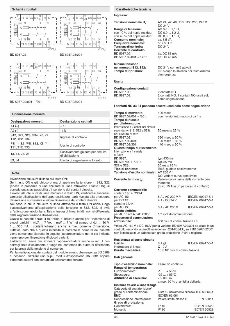
36 BD 5987 / 19.04.17 it / 962
Ingresso Tensione nominale UN: AC 24, 42, 48, 110, 127, 230, 240 V DC 24 VRange di tensione: AC 0,8 ... 1,1 UNcon 10 % del ripple residuo: DC 0,9 ... 1,2 UN con 48 % del ripple residuo: DC 0,8 ... 1,1 UNConsumo nominale: ca. 5,5 VAFrequenza nominale: 50 / 60 HzTensione di controllo: DC 24 VCorrente di controllo: BD 5987.02: tip. DC 55 mABD 5987.02/001 + /301: tip. DC 45 mA
Minima tensione nei morsetti S12, S22: DC 21 V con relé attivati Tempo di ripristino: 0,5 s dopo lo sblocco dei tasto arresto d'emergenza
Uscita
Configurazione contattiBD 5987.02: 2 contatti NOBD 5987.03: 2 contatti NO, 1 contatti NO usati solo come segnalazione
I contatti NO 33-34 possono essere usati solo come segnalazione
Tempo d'intervento: 100 msecBD 5987.02/001 + /301: con riavvio automatico circa 1 sTempo di rilascio per d'interruzioneInterruzione a 2 canali nel circuto secondario (S12, S22 e S23): 50 msec ± 25 %nel circuito di rete BD 5987.02: 350 msec ± 50 %BD 5987.02/001: 120 msec ± 50 %BD 5987.02/301: 40 msec ± 50 %Guasto tempo di rilevamento:Interruzione a 1 canale a S12:BD 5987: typ. 430 msBD 5987/001+/201: typ. 85 msS22 e S23: 50 ms ± 25 %Tipo di contatto: Relé, guidato positivamenteTensione d’uscita nominale : AC 250 V 1)
DC: vedere curva arco limiteCorrente termica Ith: Vedere curva limite della corrente per- manente (max. 10 A in un percorso di contatto)Corrente commutabilecontatti 13/14, 23/24:per AC 15: 5 A / AC 230 V 1) IEC/EN 60947-5-1per DC 13: 4 A / DC 24 V IEC/EN 60947-5-1contatto 33/44per AC 15: 3 A / AC 230 V IEC/EN 60947-5-1Durata elettricaper AC 15 a 2 A / AC 230 V: 105 cicli di commutazione Frequenza di commutazioneadmissibile: 600 cicli di commutazione / h1) max. AC 160 V o DC 160V per la variante BD 5987.02/301 se usato in un controllo secondo la directtiva ascensori 2014/33/EU, se il BD 5987.02/301 non è installat in un cabinet con grado protezione IP 54 o migliore.
Resistenza al corto-circuitofusibile: 6 A gL IEC/EN 60947-5-1interruttore di linea: C 10 ADurata meccanica: 10 x 106 cicli di commutazione
Dati generali
Tipo d’esercizio nominale: Esercizio continuoRange di temperatura:Funzionamento: -15 ... + 55°CStoccaggio: -25 ... + 85°CAltitudine di esercizio: < 2.000 m a max. 90 % di umidità dell'ariaDistanze tra aria e linee di fugaCategoria di sovratensione/grado di contaminazione: 4 kV / 2 (isolamento di base) IEC 60664-1EMC IEC/EN 62 061 Soppressione interferenze: Valore limite classe B EN 55011Grado di protezione: Contenitore: IP 40 IEC/EN 60529Morsetti: IP 20 IEC/EN 60529
Rivelazione chiusura di linea sul tasto ON: Se il tasto ON è già chiuso prima di applicare la tensione in S12, S22 (anche in presenza di una chiusura di linea attraverso il tasto ON), si esclude qualsiasi possibilità d'inserzione dei contatti d'uscita. L'eventuale chiusura di linea mediante il taslo ON, verificatasi successi-vamente all'attivazione dell'apparecchiatura, sarà rivelata alla procedura d'inserzione successiva e inibirà I'inserzione dei contatti d'uscita. Nel caso in cui la chiusura di linea attraverso il tasto ON abbia luogo successivamente all'applicazione della tensione in S12, S22, si avrà un'attivazione involontaria. Tale chiusura di linea, infatti, non si differenzia dalla regolare funzione d'inserzione. Grazie ai contatti dorati, il BO 5988 è indicato anche per I'inserzione di piccoli carichi 1 mVA ... 7 VA, 1 mW ... 7 W nel campo di 0,1 ... 60 V, 1 ... 300 mA. I contatti tollerano anche la max. corrente d'inserzione. Tuttavia, dato che a questa intensità di corrente la doratura dei contatti viene comunque distrutta, in seguito I'apparecchiatura non è più indicata nemmeno per I'inserzione di piccoli carichi. L'attacco PE serve per azionare I'apparecchiatura anche in reti IT con sorveglianza d'isolamento e funge nel contempo da punto di riferimento per la prova della tensione di comando. Per la multiplazione dei contatti del modulo arresto d'emergenza BO 5988 si possono utilizzare uno o più moduli d'espansione BN 3081 oppure contattori esterni con contatti ad azionamento forzato.
Connessione morsetti
Designazione morsetti Designazione segnaliA1 (+) + / L
A2 (-) - / N
S12, S22, S23, S34, X6, Y2 T12, T22, T34
Ingressi di controllo
PE (-), S21/PE, S33, X5, Y1 T11, T12, T33
Uscite di controllo
13, 14, 23, 24Positivamente guidato per circuito di abilitazione
33, 34 Uscita di segnalazione forzato
Schemi circuitali Caratteristiche tecniche
Nota
K3
K2
Y2 PE
A1 Y1
S33
S12
S22
S34
A2
23
2414
13
S12 S12 S34
S33
S33 S33
A1(+)
PE(-)
S22
14 24
Y113 23 Y2
A2(-)
M7375_b
K3
K2
K1
X6 PE
A1 X5
S33
S12
S22
S34
A2
23
24 34
33
14
13
33 S34
S21/PE
34 X6X5
A1(+)
S22S12
14 24
S2313 23 S33
A2(-)
M7378_b
K3
K2
X6 PE
A1 X5
S33
S12
S22
S34
A2
23
2414
13
S12 S34
S21/PE
S33 X6X5
A1(+)
S22S12
14 24
S2313 23 S33
A2(-)
M7376_b
K3
K2
K1
X6 PE
A1 T11
T33
T12
T22
T34
A2
23
24 34
33
14
13
33 T34
PE
34 X6T33
A1(+)
T22T12
14 24
S2313 23 T11
A2(-)
M7379_c
BD 5987.02 BD 5987.03/001
BD 5987.02/001 + /301 BD 5987.03/201

37 BD 5987 / 19.04.17 it / 962
Contenitore: Termoplastico con V0 secondo UL 94Resistenza alle vibrazioni: Ampiezza 0,35 mm Frequenza 10 ... 55 Hz, IEC/EN 60068-2-6Resistenza climatica: 15 / 055 / 04 IEC/EN 60068-1Siglatura dei morsetti: EN 50005Collegamento conduttore: 1 x 4 mm2 filo rigido oppure 1 x 2,5 mm2 filo flessibili e capicorda isolato oppure 2 x 1,5 mm2 filo flessibili e capicorda isolato oppure DIN 46228-1/-2/-3/-4 2 x 2,5 mm2 filo flessibili DIN 46228-1/-2/-3Fissaggio conduttore: Viti per morsetti M3,5 Terminali con protezione del conduttoreMontaggio rapido: su guida DIN IEC/EN 60715Peso netto: 450 g
Dimensioni Larghezza x Altezza x Profondità
45 x 74 x 121 mm
BD 5987.02/001 DC 24 VNumero articolo: 0040954• Uscita: 2 contatti NO• a richiesta funzione ON automatica all'applicazione della tensione
d'esercizio o attivazione mediante il tasto ON• Tensione nominale UN: DC 24 V• Larghezza: 45 mm
BD 5987.02/61: con omologazione UL (Canada/USA)BD 5987.02/001: a richiesta rivelazione chiusure in parallelo nel circuito di comando arresto d'emergenza (esempio M6904)Equipaggiamento dei ponticelli per le funzioni :attivazione mediante tasto ON / oppure funzione ON automatica
M8687
Tasto ONS12-S34 oS33-S34
PonticelloX5 - X6
Funzione
Intervento dei contatti d'uscita solo in seguito all'attivazione dei tasto ON . Sorveglianza chiusura di linea sul tasto ON.
Funzione ON automalica per tensio-ne d'esercizio OFF 1 ON oppure allo sblocco dell'arresto d'emergenza.
BD 5987.03/001: co 2 contatti NO, 1 contatto indicatore AC/DC 0,1 ... 1 A / 10 ...120 V
BD 5987.03/201: come BD 5987.03/001, ma con definizione speciale dei morsettiEquipaggiamento dei ponticelli per le funzioni :attivazione mediante tasto ON / oppure funzione ON automatica
M8687
Tasto ONT11-T34 oT12-T34
PonticelloT33 - X6
Funzione
Intervento dei contatti d'uscita solo in seguito all'attivazione dei tasto ON . Sorveglianza chiusura di linea sul tasto ON.
Funzione ON automalica per tensio-ne d'esercizio OFF 1 ON oppure allo sblocco dell'arresto d'emergenza.
BD 5987.03/301: Comportamento iniziale come BD 5987.02/001, tempo rilascio abbreviato ad apertura alimentazione adatto per ascensori secondo la norma EN 81-20/-50 Secondo le richieste della direttiva 2014/33/EU per gli ascensori
Esempi d’ordinazione per varianti
BD 5987 .02 /_ _ _ AC 230 V 50 / 60 Hz
Frequenza nominale Tensione nominale Variante, se richiesta Contatti Tipo
Tipo standard
Varianti
Caratteristiche tecniche
Manutenzione e riparazione
- Il dispositivo non contiene componenti avevano bisogno di manutenzione - In caso di guasto, non aprire il dispositavo, ma inviarlo al produttore
per la riparazione.
Procedere quando i disturbi
Errore Possibile causa
Non si accende il LED „Netz“ - Non è collegata l‘alimentazione
Si accende il LED „K2“ ma il „K3“rimane spento
- Il relè di sicurezza K2 è incollato (sostituire il dispositivo)- A 1-spegnimento del canale su S22, T22 o S23 (spegnere il canale su S12 o T12)
Si accende il LED „K3“ ma il „K2“rimane spento
- Il relè di sicurezza K3 è incollato (sostituire il dispositivo)- A 1-spegnimento del canale su S12, o T12 (spegnere il canale su S22, T22 o S23)
Impossibile attivare l‘apparecchio
- Un relè di sicurezza è incollato (sostituire il dispositivo) - Modalità di accensione su manuale:- Problema di linea sul pulsante di start (togliere l‘alimentazione ed eliminare il difetto) - Modalità di accensione automatica: X5 - X6 o T33 - X6 non ponticellati
Tensione nominale UN: AC 24, 42, 48, 110, 127, 230, 240 V DC 24 V
Temperatura ambiente: - 15 … + 55 °C
Corrente commutabile: 6 A, 250 Vac G.P
Connessione: solo per i 60° C / 75° C in rarne conduttori AWG 18 - 16 Torque 7 lb in
nfoLa mancanza di dati tecnici in esso contenute non in modo esplicito , sono i seguenti generale tecnico i dati si riferiscono.
Dati UL
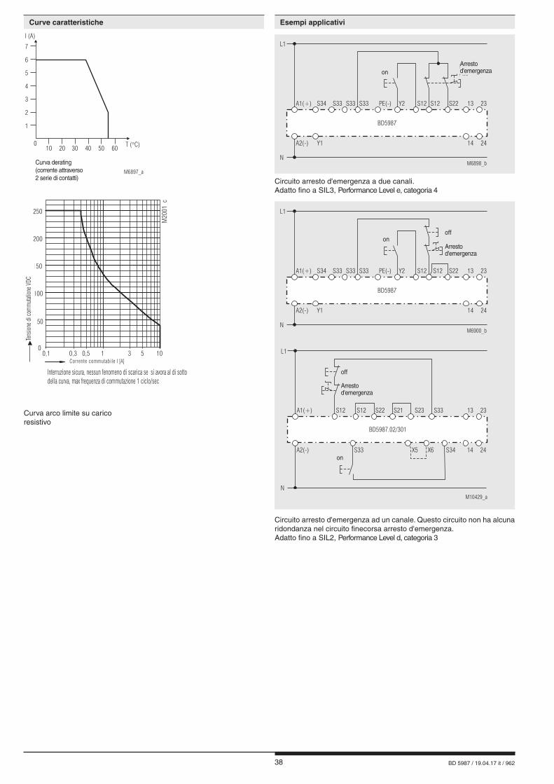
38 BD 5987 / 19.04.17 it / 962
00,1 0,3 0,5 1 3 5 10
Schaltstrom A
50
100
150
250
200
Scha
ltspa
nnun
gVD
C
M20
01_c
Sicheres Abschalten, kein stehender Lichtbogen,max. 1 Schaltspiel / s
Circuito arresto d'emergenza a due canali. Adatto fino a SIL3, Performance Level e, categoria 4
Circuito arresto d'emergenza ad un canale. Questo circuito non ha alcuna ridondanza nel circuito finecorsa arresto d'emergenza.Adatto fino a SIL2, Performance Level d, categoria 3
L1
M10429_a
A1(+)
BD5987.02/301
Aus
Not-Aus
N
A2(-) X5 X6 S34 14 24
Ein
S12 S12 S22 S21 S23 S33 13 23
S33
L1
M6900_bN
A2(-)
A1(+) S33S34 S33 S33 PE(-) Y2 S12 S12 S22
BD5987
Ein
Aus
Not-Aus
Y1
13 23
14 24
Arrestod'emergenza
off
on
onoff
Arrestod'emergenza
1
010
Dauerstromgrenzkurve(Strom über 2 Kontaktreihen)
20 30 40 50T ( C)�
60
M6897_a
2
3
4
5
6
7
I (A)
Curva derating(corrente attraverso 2 serie di contatti)
Curva arco limite su carico resistivo
Corrente commutabile l [A]
Ten
sione
di c
omm
utatio
ne V
DC▶
Interruzione sicura, nessun fenomeno di scarica se si avora al di sotto della curva, max frequenza di commutazione 1 ciclo/sec
Curve caratteristiche Esempi applicativi
L1
M6898_bN
Not-Aus
A2(-)
A1(+) S33S34 S33 S33 PE(-) Y2 S12 S12 S22
Y1
BD5987
13 23
14 24
Ein
Arrestod'emergenzaon
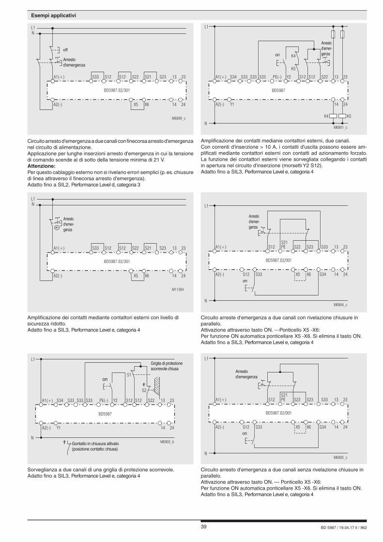
39 BD 5987 / 19.04.17 it / 962
Circuito arresto d'emergenza a due canali senza rivelazione chiusure inparallelo.Attivazione attraverso tasto ON. --- Ponticello X5 -X6:Per funzione ON automatica ponticellare X5 -X6. Si elimina il tasto ON.Adatto fino a SIL3, Performance Level e, categoria 4
Amplificazione dei contatti mediante contattori esterni con livello di sicurezza ridotto.Adatto fino a SIL3, Performance Level e, categoria 4
Circuito arreste d'emergenza a due canali con rivelazione chiusure inparallelo.Attivazione attraverso tasto ON. ---Ponticello X5 -X6:Per funzione ON automatica ponticellare X5 -X6. Si elimina il tasto ON.Adatto fino a SIL3, Performance Level e, categoria 4
Sorveglianza a due canali di una griglia di protezione scorrevole. Adatto fino a SIL3, Performance Level e, categoria 4
Circuito arresto d'emergenza a due canali con finecorsa arresto d'emergenza nel circuito di alimentazione.Applicazione per lunghe inserzioni arresto d'emergenza in cui la tensionedi comando scende al di sotto della tensione minima di 21 V.Attenzione: Per questo cablaggio esterno non si rivelano errori semplici (p. es. chiusure di linea attraverso iI finecorsa arresto d'emergenza).Adatto fino a SIL2, Performance Level d, categoria 3
Amplificazione dei contatti medianie contattori esterni, due canali.Con correnti d'inserzione > 10 A, i contatti d'uscita possono essere am-plificati mediante contattori esterni con contatti ad azionamento forzato. La funzione dei contattori esterni viene sorvegliata collegando i contatti in apertura nel circuito d'inserzione (morsetti Y2 S12).Adatto fino a SIL3, Performance Level e, categoria 4
L1
M6903_bN
A2(-)
A1(+) S33S34 S33 S33 PE(-) Y2 S12 S12 S22
Y1
BD5987
13 23
14 24
Ein
betätigter Schließer(Kontaktstellung: geschlossen)
S1
S2
Schiebeschutzgittergeschlossen
Griglia di protezione scorrevole chiusa
Gontatto in chiusura attivato (posizione contatto: chiusa)
onon
L1
M6905_cN
Not-Aus
A2(-)
A1(+)S21PE S33S23S22S12
X5S33S12 X6 S34
BD5987.02/001
13 23
14 24
Einon
Arrestod'emergenza
L1
M6904_cN
Not-Aus
A2(-)
A1(+)S21PE S33S23S22S12
X5S33S12 X6 S34
BD5987.02/001
13 23
14 24
Ein
Arrestod'emer-genza
on
M6899_c
Aus
Not-Aus
L1
A1(+)
BD5987.02/301
N
A2(-) X5 X6 14 24
S12 S22S12 S21 S23S33 13 23
Arrestod'emergenza
off
L1
M6901_cN
Not-Aus
A2(-)
A1(+) S33S34 S33 S33 PE(-) Y2 S12 S12 S22
Y1
BD5987
13 23
14 24
K4
K5
Ein
K4 K5
Arrestod'emer-genzaon
Esempi applicativi
M11384
Not-Aus
L1
A1(+)
BD5987.02/301
N
A2(-) X5 X6 14 24
S12 S22S12 S21 S23S33 13 23
Arrestod'emer-genza

40 BD 5987 / 19.04.17 it / 962
E. DOLD & SÖHNE KG • D-78114 Furtwangene-mail: [email protected] • internet: http://www.dold.com
• PO Box 1251 • Telefono (+49) 77 23 / 654-0 • Fax (+49) 77 23 / 654-356
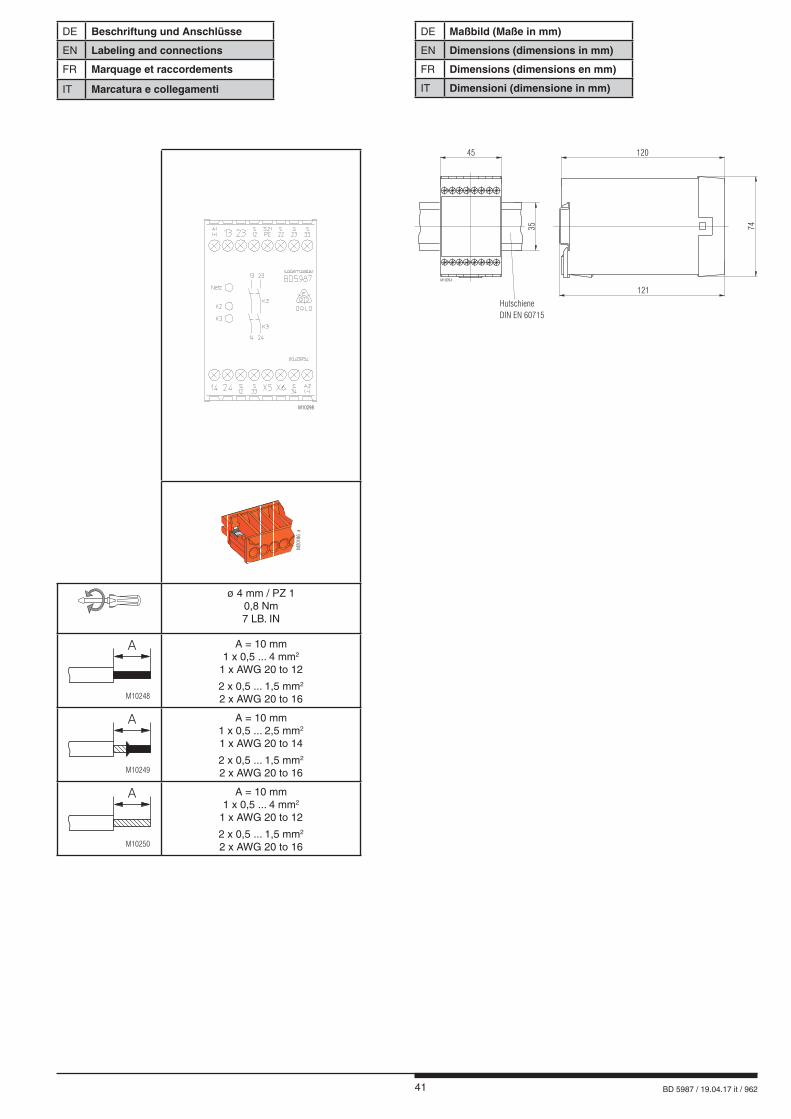
41 BD 5987 / 19.04.17 it / 962
DE Beschriftung und Anschlüsse
EN Labeling and connections
FR Marquage et raccordements
IT Marcatura e collegamenti
M10298
M20
186_
a
ø 4 mm / PZ 10,8 Nm7 LB. IN
M10248
A A = 10 mm1 x 0,5 ... 4 mm2
1 x AWG 20 to 12
2 x 0,5 ... 1,5 mm2
2 x AWG 20 to 16
M10249
A A = 10 mm1 x 0,5 ... 2,5 mm2
1 x AWG 20 to 14
2 x 0,5 ... 1,5 mm2
2 x AWG 20 to 16
M10250
A A = 10 mm1 x 0,5 ... 4 mm2
1 x AWG 20 to 12
2 x 0,5 ... 1,5 mm2
2 x AWG 20 to 16
M10054
35
120
121
74
Hutschiene
DIN EN 60715
45
DE Maßbild (Maße in mm)
EN Dimensions (dimensions in mm)
FR Dimensions (dimensions en mm)
IT Dimensioni (dimensione in mm)
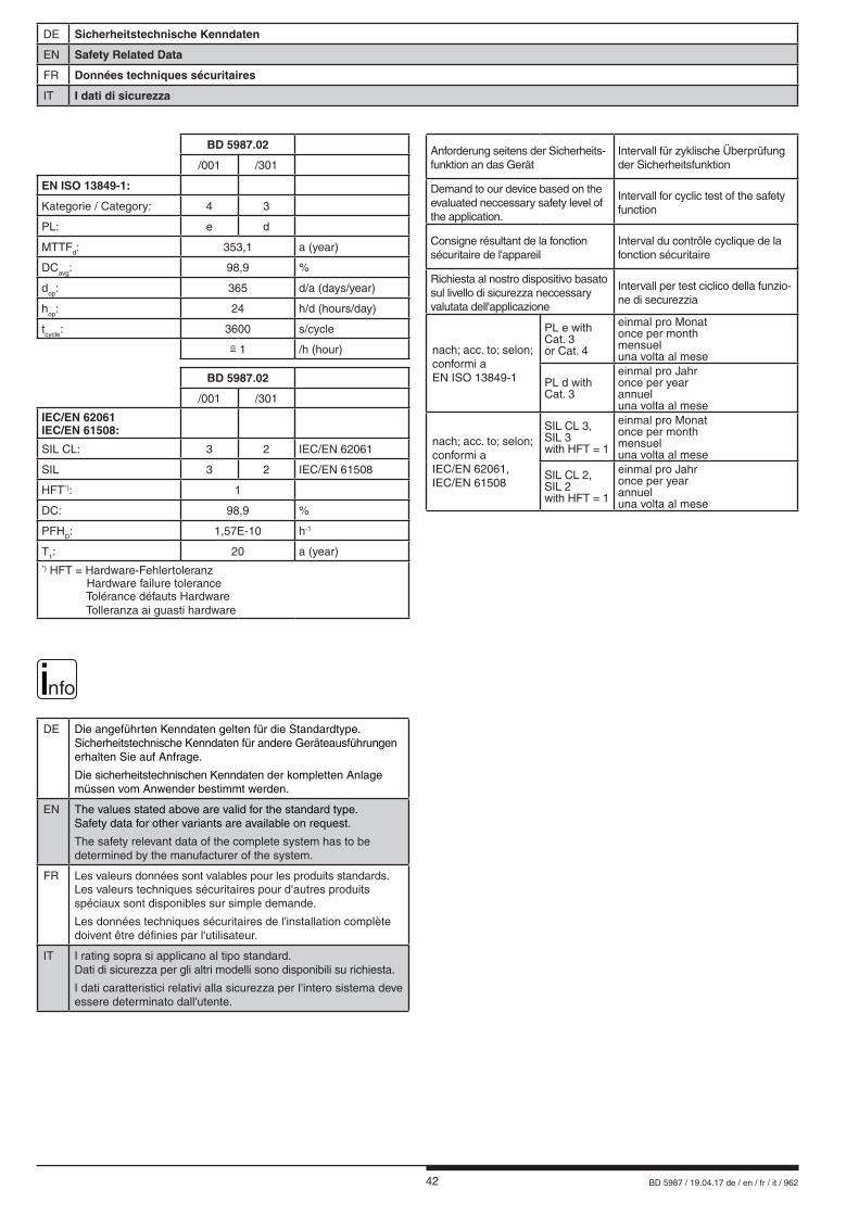
42 BD 5987 / 19.04.17 de / en / fr / it / 962
DE Sicherheitstechnische Kenndaten
EN Safety Related Data
FR Données techniques sécuritaires
IT I dati di sicurezza
nfo
DE Die angeführten Kenndaten gelten für die Standardtype. Sicherheitstechnische Kenndaten für andere Geräteausführungen erhalten Sie auf Anfrage.
Die sicherheitstechnischen Kenndaten der kompletten Anlagemüssen vom Anwender bestimmt werden.
EN The values stated above are valid for the standard type.Safety data for other variants are available on request.
The safety relevant data of the complete system has to be determined by the manufacturer of the system.
FR Les valeurs données sont valables pour les produits standards.Les valeurs techniques sécuritaires pour d‘autres produits spéciaux sont disponibles sur simple demande.
Les données techniques sécuritaires de l'installation complète doivent être définies par l'utilisateur.
IT I rating sopra si applicano al tipo standard. Dati di sicurezza per gli altri modelli sono disponibili su richiesta.
I dati caratteristici relativi alla sicurezza per I'intero sistema deve essere determinato dall'utente.
Anforderung seitens der Sicherheits- funktion an das Gerät
Intervall für zyklische Überprüfung der Sicherheitsfunktion
Demand to our device based on the evaluated neccessary safety level of the application.
Intervall for cyclic test of the safety function
Consigne résultant de la fonction sécuritaire de l'appareil
Interval du contrôle cyclique de la fonction sécuritaire
Richiesta al nostro dispositivo basato sul livello di sicurezza neccessary valutata dell'applicazione
Intervall per test ciclico della funzio-ne di securezzia
nach; acc. to; selon;conformi aEN ISO 13849-1
PL e with Cat. 3 or Cat. 4
einmal pro Monatonce per monthmensueluna volta al mese
PL d with Cat. 3
einmal pro Jahronce per yearannueluna volta al mese
nach; acc. to; selon;conformi a IEC/EN 62061, IEC/EN 61508
SIL CL 3,SIL 3with HFT = 1
einmal pro Monatonce per monthmensueluna volta al mese
SIL CL 2,SIL 2with HFT = 1
einmal pro Jahronce per yearannueluna volta al mese
BD 5987.02
/001 /301
EN ISO 13849-1:
Kategorie / Category: 4 3
PL: e d
MTTFd: 353,1 a (year)
DCavg: 98,9 %
dop: 365 d/a (days/year)
hop: 24 h/d (hours/day)
tcycle: 3600 s/cycle
= 1 /h (hour)
BD 5987.02
/001 /301
IEC/EN 62061IEC/EN 61508:
SIL CL: 3 2 IEC/EN 62061
SIL 3 2 IEC/EN 61508
HFT*): 1
DC: 98,9 %
PFHD: 1,57E-10 h-1
T1: 20 a (year)*) HFT = Hardware-Fehlertoleranz Hardware failure tolerance Tolérance défauts Hardware Tolleranza ai guasti hardware
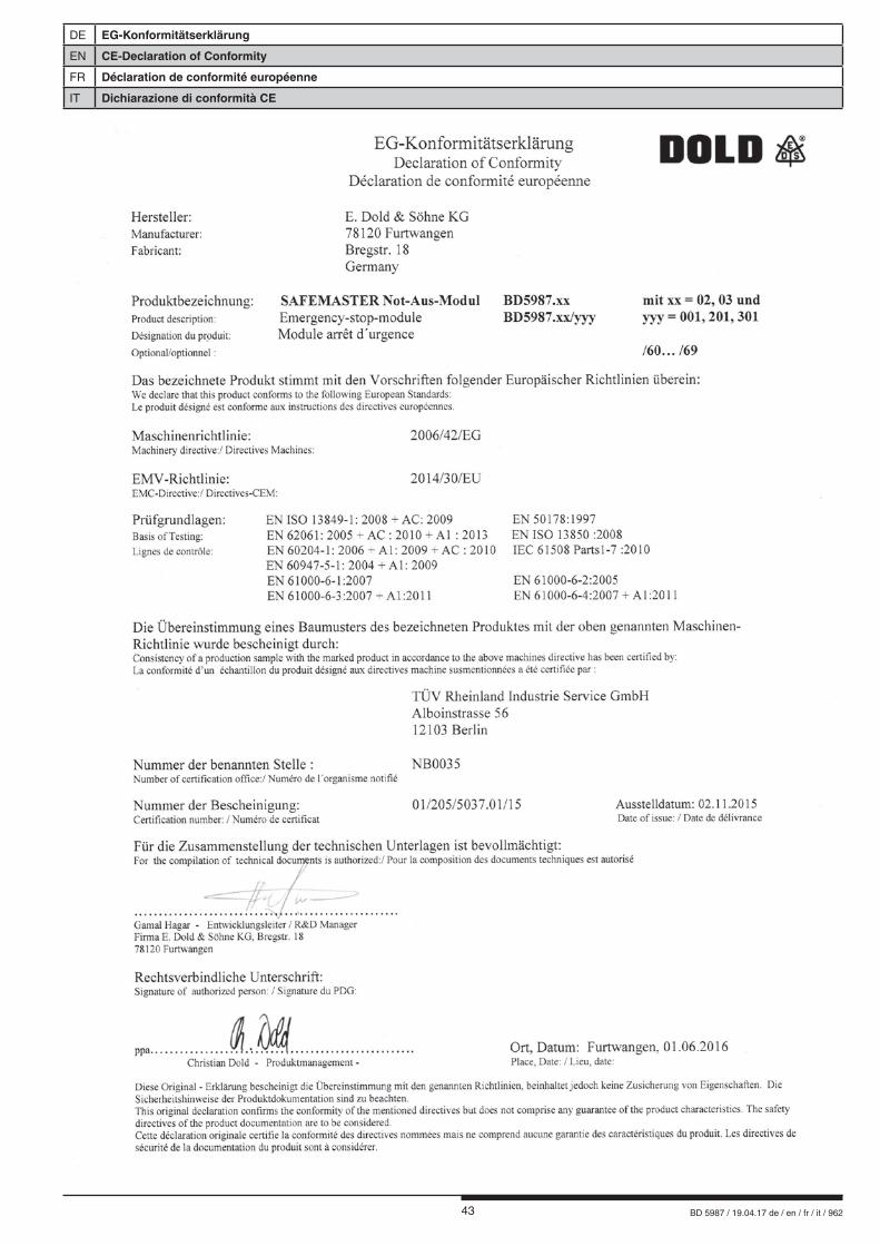
43 BD 5987 / 19.04.17 de / en / fr / it / 962
DE EG-Konformitätserklärung
EN CE-Declaration of Conformity
FR Déclaration de conformité européenne
IT Dichiarazione di conformità CE
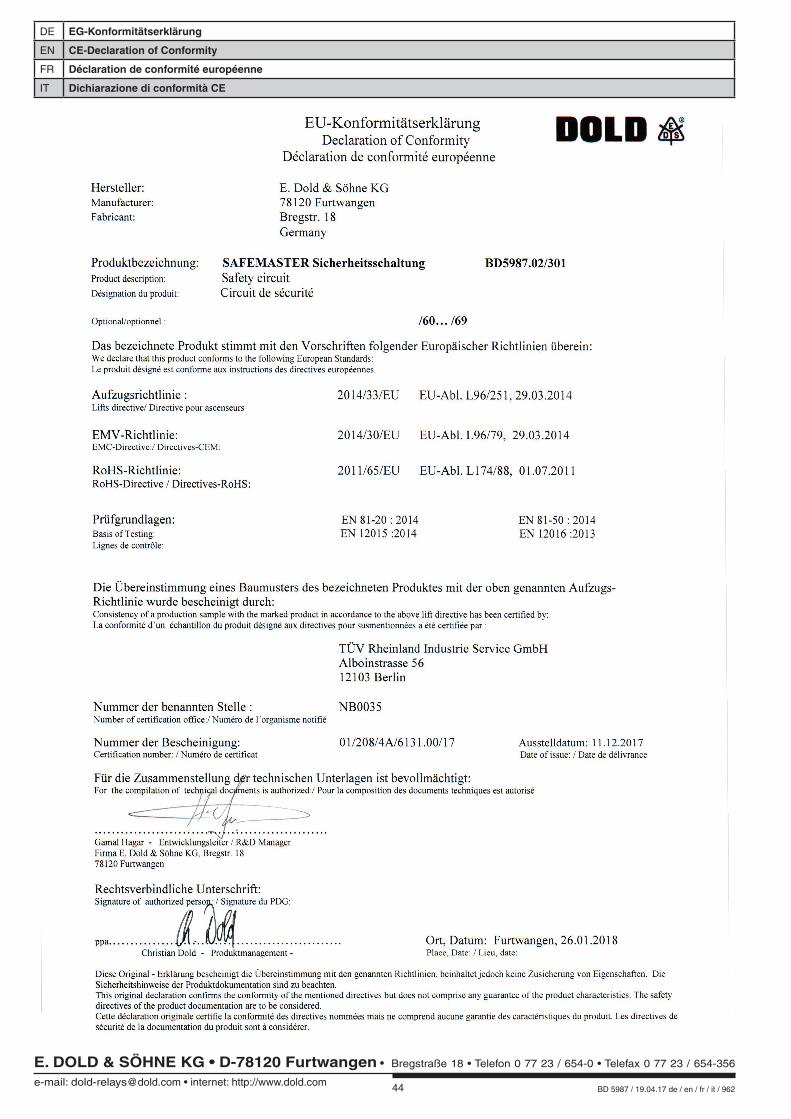
44 BD 5987 / 19.04.17 de / en / fr / it / 962
DE EG-Konformitätserklärung
EN CE-Declaration of Conformity
FR Déclaration de conformité européenne
IT Dichiarazione di conformità CE
E. DOLD & SÖHNE KG • D-78120 Furtwangene-mail: [email protected] • internet: http://www.dold.com
• Bregstraße 18 • Telefon 0 77 23 / 654-0 • Telefax 0 77 23 / 654-356


![l>lf·· E ·B; -I,:,C-·-1·1V · cat. no.i bd lj.657 bd lj.6]5 bd 4630 bd 4·627 bd 4628 bd 4886 bd 4546 bd 4·545 bd 4544 bd 4542 bd lj,588 bd lj.593 bd 0102 bd 4636 bd 4632 bd](https://static.fdocuments.net/doc/165x107/5f7c69bb7d840d18665ab1e6/llf-e-b-ic-11v-cat-noi-bd-lj657-bd-lj65-bd-4630-bd-4627-bd-4628-bd.jpg)


