North Carolina Division of Air Quality Quality/toxics... · North Carolina Division of Air Quality...
118
North Carolina Division of Air Quality Toxics Protection Branch Recycled Oil Management Plan January 2013
Transcript of North Carolina Division of Air Quality Quality/toxics... · North Carolina Division of Air Quality...

North Carolina
Division of Air Quality
Toxics Protection Branch
Recycled Oil Management Plan
January 2013

Recycled Oil Management Plan Rev. 1: 08/29/01
Rev. 2: 12/9/02
2
PREFACE
The Plan provides guidance to the processors/refiners of recycled oil to obtain approval from the
DAQ to distribute in the State of North Carolina recycled oil that is equivalent “unadulterated
fuel”. Chemical parameters with recommended analytical methodologies are tabulated in the Plan
to establish equivalency to “unadulterated fuel”. The Plan provides guidance to the DAQ
personnel, recycled oil processors and combustors/burners.
This document also includes details of recycled oil sampling using a variety of sample collection
devices from different and varied sources. Details of field activities and sample handling
procedures are also included. The samples are generally collected from industrial and/or
commercial facilities that have an air quality permit to combust/burn recycled oil.
Recycled Oil Management Plan Rev. 1: 12/9/02
3
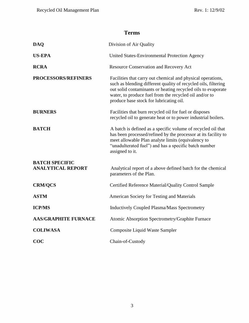
Terms
DAQ Division of Air Quality
US-EPA United States-Environmental Protection Agency
RCRA Resource Conservation and Recovery Act
PROCESSORS/REFINERS Facilities that carry out chemical and physical operations,
such as blending different quality of recycled oils, filtering
out solid contaminants or heating recycled oils to evaporate
water, to produce fuel from the recycled oil and/or to
produce base stock for lubricating oil.
BURNERS Facilities that burn recycled oil for fuel or disposes
recycled oil to generate heat or to power industrial boilers.
BATCH A batch is defined as a specific volume of recycled oil that
has been processed/refined by the processor at its facility to
meet allowable Plan analyte limits (equivalency to
“unadulterated fuel”) and has a specific batch number
assigned to it.
BATCH SPECIFIC
ANALYTICAL REPORT Analytical report of a above defined batch for the chemical
parameters of the Plan.
CRM/QCS Certified Reference Material/Quality Control Sample
ASTM American Society for Testing and Materials
ICP/MS Inductively Coupled Plasma/Mass Spectrometry
AAS/GRAPHITE FURNACE Atomic Absorption Spectrometry/Graphite Furnace
COLIWASA Composite Liquid Waste Sampler
COC Chain-of-Custody

Recycled Oil Management Plan Rev. 1: 08/29/01
Rev. 2: 12/9/02
Rev. 3: 5/5/04
Rev. 4: 3/26/09
4
Table of Contents
Sections Page 1.0 Plan Objective …………………………………………………………….. 6
2.0 Background ……………………………………………………………….. 6
3.0 Program Plan ……………………………………………………………… 8
3.1 Processor/Refiner ………………………………………………….. 8
3.1.1 Approval Requirements Processors/Refiners……………….9
3.1.2 Operating Requirements for An Approval
Vendor/Processor…………………………………………...12
3.1.3 Requirement for Re-Approval of Vendor/Processor………..12
3.2 Requirements for Burners ……………………………….………… 15
3.3 Definition of Unadulterated Fuel …………………………………. 16
3.4 Recycled Oil Analytical Guidelines ……………………………… 16
4.0 Sampling of Recycled Oil …………………………………………………. 18
4.1 Safety ……………………………………………………………… 19
4.2 Arrival at Facility …………………………………………………. 19
4.3 Sampling Equipment ……………………………………………… 20
4.4 Sample Container …………………………………………………. 20
4.5 Sample Volume …………………………………………………… 20
4.6 Sample Labeling and Identification ………………………………. 22
4.7 Sample Storage and Transportation ………………………………. 22
5.0 Recycled Oil Sample Collection Program ………………………………. 22
5.1 Manual Burner Pipeline Sampling ………………………………... 23
5.2 Storage Tanks and Tank Cars …………………………………….. 23
5.3 Drums, Barrels and Cans …………………………………………. 24
6.0 Recycled Oil Sample Analyses Program ………………………………….. 24
References ……………………………………………………………………………… 26
Tables Table 1 – Comparison of Virgin Oil vs Recycled Motor Oil ………………………….. 7
Table 2 – Recycled Oil Analytical Guidelines ………………………………………… 14
Table 3 – Laboratory Quality Assurance……………………………………………….. 18
Table 4 – Summary of Activities Related to Recycled Oil Collection ………………… 19
Table 5 – Recycled Oil Sample Analysis Plan ………………………………………… 24
Figures Figure 1 - Initial Processor Approval Process Flowchart…………………………………11
Figure 2 - Activities After Receipt of Samples by Laboratory ………………………… ..25

Recycled Oil Management Plan Rev. 1: 08/29/01
Rev. 2: 12/9/02
Rev. 3: 4/25/06
Rev. 4: 9/15/06
Rev. 5: 3/26/09
5
Attachments Attachment 1 - Memorandum of June 11, 1991,Used Oil Burning and Air Permitting
Requirements; Memorandum of June 11, 1991, Definition of
Unadulterated Fuel; Memorandum of June 11, 1991, Used Oil Analytical
Guidelines (No. 2 fuel oil); and Memorandum of July 22, 1991, Used #4
Residual Oil Analytical Guidelines.
Attachment 2 - Drum-Tanker-Rail Car COLIWASA and Drum Thief
Attachment 3 - Recycled Oil Sample Report Form
Attachment 4 - Chain-of-Custody Form
Attachment 5 - ASTM D5495-94, Standard Practice for Sampling With a Composite
Liquid Waste Sampler (COLIWASA)
Attachment 6 - Notice of Enforcement Policy
Attachment 7 - Example Form of Recycled Oil Analytical Report and Batch Signature
Information
Attachment 8 - North Carolina Approved List of Recycled Oil Suppliers (as of 2/13/2009)
Attachment 9 - Recycled Oil Permitting Procedures
Attachment 10- On-site Generated Waste (Recycled) Oil Combustion
Attachment 11- Method 3052: Microwave Assisted Acid Digestion of Siliceous and
Organically Based Matrices
Attachment 12- Method 6010B: Inductively Coupled Plasma-Atomic Emission Spectrometry
Attachment 13- Method 6020: Inductively Coupled Plasma – Mass Spectrometry
Attachment 14- Standard Operating Procedure for Recycled Oil Sample Collection
Attachment 15- Recycled Oil Sample Aliquoting

Recycled Oil Management Plan Rev. 1: 08/29/01
Rev. 2: 12/9/02
6
1.0 PLAN OBJECTIVES:
The objective of the plan is to ensure that burners of recycled oil are complying with appropriate
regulatory requirements delineated in their air permit. The plan establishes a physical compliance
and enforcement mechanism for the Division of Air Quality (DAQ) through specific guidelines
for recycled oil sample collection and analyses of relevant chemical parameters.
Included in this plan are details of the approval procedures for recycled oil processors that are
planning to distribute their product in North Carolina. The evaluation process involves the
determination of whether recycled oil can be deemed equivalent to virgin unadulterated oil.
Implementation of this plan seeks to ensure that all air permit holders using recycled oil that
DAQ has approved as equivalent to “Unadulterated Fuel,” as defined herein, are meeting
relevant requirements. A goal of this plan is also to manage data collection on the quantity of
recycled oil burned in North Carolina by facilities holding air permits.
2.0 BACKGROUND:
Recycled oil is defined by US-EPA (1)a
under 40 CFR Part 279 as any oil, that has been refined
from crude oil or synthetic oil, which has been used and as a result of such use is contaminated
by physical or chemical impurities. In the text of this plan, all references to recycled and/or
used, waste, or self generated oil are intended to carry the same meaning.
Recycled oil includes oils that are used as hydraulic fluids as well as oils that are used to
lubricate automobile engines and other machinery or suspend materials in industrial processes.
Oils used for these purposes can be contaminated (2-4) because:
● Engine heat can break down oil additives and other constituents in the oil.
● Dirt, dust and rust can get into the engine crankcase and be transferred into the oil.
● Metal particles from engine wear can also contaminate oil directly.
● Exhaust gases from combustion in the engine can leak through the engine piston rings
and into the oil, thus contaminating the oil with gasoline and gasoline combustion
products.
● Fluids such as water and antifreeze can leak into the oil during engine operation.
Because of the changes that occur during use, motor oils tend to differ in chemical and physical
composition from virgin oil (see Table 1). In general recycled oils have (2):
● Much higher water and sediment levels than virgin oil.
● Relatively higher concentrations of toxic organic compounds.
● Relatively higher levels of metals such as As, Cd, Cr, Pb, etc.
a Throughout the text, numbers in parenthesis indicate reference numbers.

Recycled Oil Management Plan Rev. 1: 08/29/01
Rev. 2: 12/9/02
7
TABLE 1. Comparison of Virgin Oil vs Recycled Motor Oil*
Constituent Virgin Motor Oil
(Range, PPM)
Recycled Motor Oil
(Range, PPM)
Cadmium 0 0.5 - 3.4
Chromium 0 0.8 - 2.3
Lead 0.03 – 0.28 5.5 – 150
* For details see references 4 and 5.
If managed properly, recycled oil is an valuable resource that can be reused as a base stock for
new lubricating oil or as a fuel, since it has a high BTU content. However, if managed
improperly, recycled oil can threaten human health and cause damage to the environment.
Federal regulations mandate (6) that used (or recycled) oil must be tested before disposal, and if
found hazardous, should be disposed of as hazardous waste under Subtitle C of RCRA (Resource
Conservation and Recovery Act). However, if the oil is determined not to be hazardous, it may
be disposed of in accordance with RCRA, Subtitle D. In either case, the regulatory requirements
are designed to prevent recycled oil from endangering human health and the environment
through the disposal process.
Further, US-EPA on September 10, 1992 published (6) its decision not to list recycled oil that is
destined for recycling as a hazardous waste. Because Used Oil Management Standards required
used oils to be managed in an environmentally safe manner, listing used oil that is to be recycled
as a hazardous waste has been considered to be unnecessary by the US-EPA (1). In other words,
used oil destined for recycling would be subjected to the Federal Used Oil Management
Standards. Waste oil destined for disposal as hazardous waste would be subjected to
requirements in RCRA Subtitle C and non-hazardous waste oil would be subjected to
requirements in RCRA Subtitle D.
As per US-EPA (6) the key groups involved in this recycling system are:
● Generators: Are those who introduce used oil into the used oil management
system including automotive generators, industrial generators, do-it-yourself etc.,
● Transporters: Are those that transport/carry used oil from generators to those
who recycle or otherwise process.
● Transfer Facilities: Any transportation related sites, e.g. loading docks or
parking lots where shipments of used oil are held for more than 24 hours and less
than 35 days.
● Processors/Refiners: Facilities that carry out chemical and physical operations,
such as blending different quality of recycled oils, filtering out solid contaminants
or heating recycled oil to evaporate water, to produce fuel oil from recycled oil
and/or to produce base stock for lubricating oil.
● Burners: Facilities that burn recycled oil for fuel or disposes recycled oil to
generate heat or to power industrial operations.
Recycled Oil Management Plan Rev. 1: 08/29/01
Rev. 2: 12/9/02
Rev. 3: 5/5/04
Rev. 4: 4/25/06
Rev. 5: 3/26/09
8
● Marketers: Persons/facilities that either determine that used oil meets burning
specifications or direct shipments of off-specification recycled oil from their
facility to a used oil burner.
Of the above mentioned key groups, only processors/refiners and burners are a focus of this
Recycled Oil Management Plan. This focus is mainly because these activities may release
increased quantities of toxic chemicals into the environment relative to those from virgin oil,
thus causing environmental pollution that may have an increased risk to human health.
3.0 PROGRAM PLAN
3.1 Processor/Refiner:
A processor/refiner is a facility that applies chemical and/or physical treatments to recycled oil to
produce fuel oils, lubricants or other recycled oil derived products. Processing includes, but is
not limited to, blending recycled oil with virgin oil to meet a required fuel specification, filtration
to remove solids and sediments, simple distillation to drive off water and other contaminating
volatile compounds, chemical and physical separation and refining. Processors/refiners generally
handle large quantities of recycled oil and perform a wide variety of operations and procedures.
As a result, these procedures tend to require strict controls (7) because such operations are
potentially damaging to the environment and human health.
Federal and North Carolina regulations mandate that recycled oil must be tested to assure that the
oil is not a hazardous waste as defined in the Resource Conservation and Recovery Act (RCRA)
or polychlorinated biphenyl (PCB) wastes regulated under 40 CFR 761 and incorporated by
reference in 15A N.C.A.C. 13A .0118. Under the Recycled Oil Management Plan, recycled oil
vendors or processors collect used oil and clean it enough to sell as unadulterated fuel. Under
the Plan, the product sold as recycled oil meeting Table 2 parameter limits is approved as
essentially equivalent to virgin fuel oil because the vendor/processor typically undertakes various
treatment steps. Treatments typically involve batch processing to remove water, filtering and
demineralizing to remove solids and additives to produce a batch equivalent to fuel oil. Once
treatment is completed for each discrete batch of recycled oil, a representative sample must be
collected and analyzed to determine whether key parameters meet Plan limits.
In addition to the stipulations under the Plan, Federal requirements under 40 CFR 761—
Polychlorinated Biphenyls (PCBs) Manufacturing, Processing, Distribution in Commerce, and
Use Prohibitions—restrict used oil from containing any quantifiable level (defined as 2 ppm) of
PCBs. To whom PCB-bearing oil can be marketed and incinerated are further restricted. Under
the Federal rules, used oil is presumed to contain quantifiable levels of PCB unless the marketer
(vendor/processor) obtains analyses (testing) or other information that refutes this claim. Other
information documenting that the used oil fuel does not contain quantifiable levels of PCBs may
consist of either personal, special knowledge of the source/ composition of the used oil, or a
certification from the generator of the oil claiming that the oil contains no detectable PCBs.
Documentation certifying a claim of no quantifiable PCBs and/or other documents relating to

Recycled Oil Management Plan Rev. 1: 08/29/01
Rev. 2: 12/9/02
Rev. 3: 5/5/04
Rev. 4: 4/25/06
Rev. 5: 3/26/09
9
transactions involving PCB-containing used oil must be part of the certification notice(s)
supplied to and by each marketer (vendor/processor). Under 40 CFR Part 279, when used oil
levels for total halogens are greater than 1,000 ppm, then there is a requirement to test for PCB to
meet the 50 ppm PCB limit
For the purposes of this Recycled Oil Management Plan, adherence to the recordkeeping
stipulations of the Federal rule serves to document a vendor/processor’s claim that their product
does not contain detectable PCBs and such documentation must accompany every delivery. An
approval for equivalency cannot be granted for used oil containing PCBs as these are absent
from virgin oil products.
If valid sample analysis results show that eight key parameters are within the parameter limits of
the Plan, and an accompanying certification indicated that the product does not contain
detectable PCB’s, then the batch is considered to be equivalent to virgin oil. The eight key
parameters subject to Plan limits are:
Eight key parameters Parameter Limits
1. Arsenic 1.0 ppm weight basis
2. Cadmium 2.0 ppm weight basis
3. Chromium 5.0 ppm weight basis
4. Lead 100 ppm weight basis
5. Total halogens 1,000 ppm weight basis
6. Sulfur * a. 0.50 % weight basis for No. 2 fuel oil
b. 2.0 % weight basis for No. 4, 5, or 6 fuel oils
7. Ash 1.0 %, weight basis
8. Minimum flash point * a. 100 ˚F for No. 2 fuel oil
b. 130 ˚F for No. 4 fuel oil
c. 175 ˚F for No. 5 or 6 fuel oils
* Note: Parameter limits differ for various fuel grades of No. 2, 4, 5, and 6 fuel oils.
ppm = parts per million
3.1.1 Initial Approval Requirements for Processors/Refiners:
In North Carolina, processors/refiners must request, in writing, for approval from the DAQ that
their refined/recycled oil be considered equivalent to virgin oil as defined in the memorandum
“Definition of Unadulterated Fuel” of June 11, 1991 (see Attachment 1 for definition) and
“Used Oil Analytical Guidelines” as specified in Table 2. Such an approval request must be
supported by submitting analytical results from at least three different batches of recycled oil
which addresses all chemical parameters included in Table 2, “Recycled Oil Analytical
Guidelines.” The analytical reports will be reviewed and evaluated for compliance with the
parameters in Table 2. The Section Chief, Technical Services Section, DAQ, will issue final
approval, for equivalence to virgin oil.

Recycled Oil Management Plan Rev. 1: 08/29/01
Rev. 2: 12/9/02
Rev. 3: 5/5/04
Rev. 4: 4/25/06
Rev. 5: 3/26/09
10
For approval, a vendor/processor must specify the recycled fuel oil equivalency number, i.e. No.
2, 4, 5, or 6 fuel oils, for which a vendor/processor plans to sell as approved recycled oil in North
Carolina. A written statement by the vendor/processor requesting approval for equivalency is
necessary and must accompany the analytical results from 3 separate batches (establishing
equivalency to virgin oil) for each recycled fuel oil number. Equivalency determination is
available for No. 2, 4, 5, or 6 fuel oils, but must be individually demonstrated for each fuel oil
number for which a vendor/processor plans to sell approved recycled oil in North Carolina.
Equivalency must be demonstrated for each discrete recycled fuel oil number (i.e., No. 2, 4, 5,
and 6). In other words, approval for one particular fuel oil number does not extend to any other
fuel oil without demonstration to and approval by DAQ.
As part of the initial approval process, processors will also be required to analyze recycled oil
Certified Reference Material (CRM)/Quality Control Samples (QCS) provided by the DAQ.
Such samples or combinations thereof, will be purchased by DAQ from a vendor who shall
certify the analyte concentrations. Results from the analysis of such CRM/QCS samples along
with analytical results of three different batches of recycled oil samples of the processor will be
considered by the Section Chief for granting approval to distribute recycled oil in the State of
North Carolina.
The following steps summarizes the initial processor approval process:
1. The processor requests approval to become an approved recycled oil supplier via written
request. This request includes analytical results of three different batches of recycled oil.
2. DAQ evaluates analytical results and the laboratory’s QA performance (see section 3.4
Note 4) of three batches for equivalency to the unadulterated recycled oil.
3. If DAQ is unable to establish equivalency via data evaluation process, then approval is
denied.
4. If DAQ is able to establish equivalency, then the processor will be requested to analyze
CRM/QCS samples.
5. DAQ evaluates CRM/QCS data and if the analytical performance QA report is
unsatisfactory, approval is denied.
6. If the analytical results and the laboratory’s QA performance are satisfactory, then DAQ
will send an approval letter to the processor to distribute the recycled oil in the State of
North Carolina.
Figure 1 is an initial processor approval process flowchart.

Recycled Oil Management Plan Rev. 1: 08/29/01
Rev. 2: 12/9/02
Rev. 3: 5/5/04
Rev. 4: 4/25/06
Rev. 5: 3/26/09
11
Figure 1
Initial Processor Approval Process Flowchart
Processor provides written
request letter, three batch
sample reports and QA
reports for each sample.
DAQ evaluates sample reports
and QA reports.
Is equivalency to the
unadulterated recycled oil
established?
Approval is
denied.
The processor will be
requested to analyze
CRM/QCS samples.
No
DAQ will send a letter to the
processor approving the
processor to distribute the
recycled oil in NC.
DAQ evaluates CRM/QCS data
and QA report.
Is it satisfactory?
Yes
Yes
No Approval is
denied.

Recycled Oil Management Plan Rev. 1: 08/29/01
Rev. 2: 12/9/02
Rev. 3: 5/5/04
Rev. 4: 4/25/06
Rev. 5: 3/26/09
12
3.1.2 Operating Requirements for An Approved Vendor/Processor
Approved vendors/processors must document and maintain organized records for a period of
three years for each of the following four key items: Facility-specific (1) tank batch volume(s);
(2) Batch analysis results; (3) Batch signature information; and (4) Delivery manifest. Failure to
perform and document fulfillment of the key operating requirements will jeopardize a
vendor/processors approval status. The following discussion describes and defines the key
operating requirements and how they are to be managed.
1. Tank batch volume(s) The recycled oil vendor/processor must certify and document the volume of each tank containing
a completely treated batch1 of recycled oil. Tank manufacturer information specifying the tank
size in gallons will be considered in determining the batch volume of each tank. A recycled oil
vendor/processor may have more than one tank at a facility to contain a completely treated batch
of recycled oil. If multiple tanks containing completely treated recycled oil are used, the
vendor/processor must establish batch volumes for each separate tank. In addition, the
vendor/processor must determine and document the batch frequency.2
2. Batch analysis results
The recycled oil vendor/processor must collect a representative sample of each batch and analyze
each batch sample for the eight key parameters using the analytical methods in Table 2. The
recycled oil vendor/processor must receive the batch analysis results and ensure the eight key
parameters meet the Table 2 Plan limits before shipping any of the batch. The recycled oil
vendor/processor must document and record representative sample analysis results3
for each
batch relative to the Plan limits for the eight key parameters on the delivery manifest showing
that the eight key parameters meet the Plan limits. The analytical report from the
vendor/processor shall be in a similar format as in Table 2 of the Plan, meaning the report shows
the analysis results along with the limits. Note: once a “batch” has been analyses no
additional material can be added in unless re-analysis occurs. And the oil cannot be sold or
distributed until satisfactory analyses are obtained and documented.
3. Batch signature information
The recycled oil vendor/processor must document and record batch signature information
uniquely identifying, and characterizing the eight key parameters in, each individual batch that
1 The term ‘batch’ is defined as a facility-specific volume of recycled oil that has been processed/treated by the
vendor/processor to meet the Plan limits (i.e., equivalency to “unadulterated fuel” in terms of the eight key
parameters). It is the size (in gallons) of the holding/storage tank containing the treated recycled oil from which a
representative sample is collected for analysis
2 The term ‘batch frequency’ is defined as the amount of time to process one (1) batch volume
3The term ‘batch analysis results’ is defined to be the results for the eight key parameters using the corresponding
appropriate sample preparation and analytical methods in Table 2 taken from a representative sample of a batch.

Recycled Oil Management Plan Rev. 1: 08/29/01
Rev. 2: 12/9/02
Rev. 3: 5/5/04
Rev. 4: 4/25/06
Rev. 5: 3/26/09
13
has undergone complete treatment. The batch signature information to accompany delivery
consists of:
a. Batch number,
b. Tank identification with batch volume of recycled oil,
c. Date and time the batch completed treatment, and
d. Volume(s) delivered to the burner facility.
4. Delivery manifest
The delivery manifest for recycled oil is the document clearly showing the shipment content and
amount, its place and date of loading and place and date of destination, as is customary in the
delivery industry. The delivery manifest from the vendor/processor to the burner shall
accompany the delivery shipment and include the batch signature information and batch analysis
results. The certification indicating that the used oil does not contain detectable (2 ppm) PCBs
shall also accompany the delivery manifest.
To set a reasonable time limit on the validity of batch analysis results, submitted analytical
results of the samples representative of the recycled oil shipment from the vendor/processor to
the burner shall be no more than one year old. This in effect limits the acceptable age of a batch
to no more than one year old without a repeat analysis documenting acceptability and assurance.
3.1.3 Requirements for Re-Approval of Vendor/Processors
After initial approval, the processor shall be re-approved every five (5) years. The re-approval
process is similar to the initial processor approval process involves the following:
1. The processor sends analytical results of three different batches of recycled oil.
2. Repeat the initial process 2 - 6.
Approximately once a year, all approved processors may also be required to analyze recycled oil
CRM/QCS submitted by DAQ to assure continual data quality. The processor’s continued
approval shall be dependent on the satisfactory performance of the CRM/QCS samples. A ±20%
deviation from the true value of the CRM/QCS samples for analyses of the Plan will be
considered as a processor’s satisfactory performance.
A list of the currently approved recycled oil processors is included as Attachment No. 8 (no
particular processor is recommended by DAQ).
The DAQ may find, through its own testing and analysis, that a specific supplier consistently
fails to comply with the parameter limits allowed for meeting the equivalency to unadulterated
virgin oil. Consequently, the supplier would be notified that he has no longer managed to
maintain his equivalency approval and consequently it will affect his approval status.

Recycled Oil Management Plan Rev. 1: 08/29/01
Rev. 2: 11/13/03
Rev. 3: 11/1/05
Rev. 4: 4/25/06
Rev. 5: 3/26/09
14
TABLE 2. Recycled Oil Parameter Limits1 and Analytical Guidelines
2
Parameter
Parameter
Limit 1
Analytical Method
3
Detection Limit (DL)
4
Arsenic (ppmw)
1.0
EPA SW- 846
3052 and 6020
0.10
Cadmium (ppmw)
2.0
EPA SW- 846
3052 and 6020
1.0
Chromium (ppmw)
5.0
EPA SW- 846
3052 and 6010B
1.0
Lead (ppmw)
100
EPA SW- 846
3052 and 6020
1.0
Total Halogens (ppmw)
1000
EPA SW- 846 9076
100
Sulfur No. 2 oil (% by
weight)
0.50
ASTM D4294
0.05
Sulfur No. 4, 5, or 6 oil (%
by weight)
2.0
ASTM D4294
0.05
Ash (% by weight)
1.0
ASTM D482-95
0.05
Flash Point Minimum
No. 2 oil (○F)
100
ASTM D56-96
NA
Flash Point Minimum
No. 4 oil (○F)
130 ASTM D-93 NA
Flash Point Minimum No. 5,
6 oil (○F)
175 ASTM D-93 NA
BTU/lb. Or BTU/gal.
NR
ASTM E771-90
0.05
Sp. Gravity, lb./gal.
NR
ASTM D287-92
0.05
Moisture %
NR
ASTM D95-83
0.05
Viscosity, SUS
4
NR
ASTM D445-96
0.05
1 = Maximum limits as per North Carolina Air Toxics regulations, except where specified as
minimum limits. Limits on Parameter 1 – 7 are on a weight basis.
2 = See subsection 3.4 for additional details under Note 1.
3 = Specified analytical method. (See Section 3.4)
4 = The minimum concentration of the analyte that can be measured with 95% confidence. NA = Detection limit not available.
ppmw = Parts per million by weight for arsenic, cadmium, chromium, lead, and total halogen

Recycled Oil Management Plan Rev. 1: 08/29/01
Rev. 2: 11/13/03
Rev. 3: 11/1/05
Rev. 4: 4/25/06
Rev. 5: 3/26/09
15
3.2 Requirements for Burners:
Burners combust recycled oil as a fuel to generate steam/heat for industrial operations. Such
facilities are required to obtain an air permit from the DAQ in order to legally operate their
combustion source in North Carolina (see Attachment 1, Air Permitting Requirements
memorandum dated June 11, 1991 and Attachment 9, Recycled Oil Permitting Procedures, draft
dated August 27, 1999). The combustion source is not required to obtain an air permit to burn
on-site generated recycled (waste) oil provided not more than 500 gallons are burned in any
single calendar year (see Attachment 10).
Facilities/sources burning recycled oil shall not accept any recycled oil without a batch specific
analytical report showing the oil to be within the parameter limits specified in Table 2 and that a
certification that the used oil does not contain detectable (2 ppm) PCBs accompanies the
analytical report. The delivery manifest from the vendor/processor shall also include batch
signature information, which consists of:
1. Batch number,
2. Tank identification with batch volume of recycled oil,
3. Date and time the batch completed treatment, and
4. Volume(s) delivered to the burner facility.
It shall be the recycled oil vendor/processor’s responsibility to deliver a manifest, PCB
certification and an analytical report of the batch delivered to the burner’s facility. Attachment 7
of the Plan presents an example form containing all the stipulated information for a manifest and
an analytical report on a single page.
It shall be the recycled oil processor’s responsibility to deliver a manifest and an analytical report
along with the batch delivery to the burner’s facility.
When an oil sample is identified as not meeting the equivalency criteria as specified in your air
quality permit, a NOTICE of VIOLATION will be issued to the facility combusting the oil even
if the approved supplier has provided you an analysis, which indicates that the recycled oil
shipment was in compliance with the unadulterated oil specifications (see Attachment 6).
The DAQ shall include a stipulation in the air permits of those facilities combusting recycled oil
that will require each facility to report to their respective Regional Office, within 30 days after
the end of each calendar year, the total gallons of recycled oil combusted at the facility for the
previous twelve (12) months (calendar year). Each Air Quality Regional Office will send copies
of all annual reports to the Toxics Protection Branch. These data may be used by to calculate the
total annual consumption of recycled oil in North Carolina.
A copy of the “Recycled Oil Permitting Procedures” is included as Attachment No. 9.

Recycled Oil Management Plan Rev. 1: 08/29/01
Rev. 2: 11/13/03
Rev.3: 09/15/06
16
3.3 Definition of Unadulterated Fuel:
In Attachment 1, the DAQ memorandum of June 11, 1991 defines “unadulterated fuel” as “fuel
oils, coal, natural gas, liquefied petroleum gas, and wood to which no toxic additives have been
added. The term toxic additives refers to additives or contaminants which could result in the
emission of toxic air pollutants of the North Carolina air toxics regulation.”
These air toxics regulations are listed in 15A NCAC 2D.1100, Control of Toxic Air Pollutants
and 15A NCAC 2Q .0700, Permit Requirements for Toxic Air Pollutants.
“Used oil is considered equivalent to unadulterated fossil fuel if toxics are demonstrated to be at
a level of no greater concern than those of unadulterated fuels. The permit applicant, or
supplier of the used oil, must demonstrate to the satisfaction of the DAQ Director that the used
oil toxic additives or contaminants are at a level such that it could be defined as unadulterated.”
3.4 Recycled Oil Analytical Guidelines:
Representative sample(s) of recycled oil must be collected as per the sampling procedure
outlined below in Sections 4, 5 and 6 and analyzed for the chemical parameters included in Table
2.
Note 1.
US-EPA SW 3052 and 6020 are the methods being specified by this Plan for recycled oil sample
analyses for arsenic, cadmium and lead. US-EPA SW 3052 and 6010B is the specified method
for chromium. Empirical work indicates that recycled oil samples must be sufficiently
digested/prepared before aspiration into the ICP/MS or an AAS graphite furnace. Further
empirical evidence derived from work with reference material oil indicate that the EPA method
3052 (see Attachment 11) does the most efficient job of destroying organic material contained in
the sample matrices, providing a clear-colored solution. The clarity of the digested solution is an
indication of the degree to which organic material in a recycled oil sample has been destroyed. If
this material is not disengaged from the sample matrix, it may interfere during the analysis
process possibly producing biased results.
A different analytical technique for chromium is necessary because empirical data suggests a
positive bias due to carbon interference under ICP/MS analysis. This bias is significantly
eliminated under ICP/AES analysis. ICP is preferred because of its multi-element capabilities.
Analytical sensitivity, specificity and reliability of As and Cd in recycled oil samples have been
determined to be improved with ICP/MS (see Attachment 12, 13).
Note 2: Processors should note that the requirements, particularly for arsenic and total halogens for
recycled oil to be distributed as a fuel for combustion in North Carolina differ somewhat from
Federal requirements given in 40 CFR Part 279 and may also differ from requirements in other
states. For arsenic, the limit is set at 1.0 PPM and for total halogens 1000 PPM. Therefore,
recycled oils containing > 1.0 PPM of arsenic and/or > 1000 PPM of total halogens are
considered to be not equivalent to “unadulterated fuel”. Such fuel type will not be burnt in the

Recycled Oil Management Plan Rev. 1: 08/29/01
Rev. 2: 11/13/03
Rev. 3: 9/15/06
Rev. 4: 3/26/09
17
DAQ permitted boilers in the State of North Carolina and must be disposed of accordingly.
Note 3:
In case a recycled oil sample is analyzed multiple times by the DAQ and/or the processor. The
reported analytical result shall represent an arithmetic mean of all analyses with a calculated
Percent Relative Standard Deviation (%RSD) from the reported mean value. The percent RSD
will be calculated by dividing the standard deviation by the mean of multiple analyses and
multiplying the resultant by 100.
Note 4:
Laboratory Quality Assurance Report
Each analysis report from laboratory should include a quality assurance report. Quality assurance
report should contain the following information:
Analysis parameter
Test method
Reporting limit
Percent recovery for lab control sample
Percent recovery for matrix spike
Results for method blank
Replicate analysis results
For metals analysis (Arsenic, Cadmium, Chromium and Lead) the acceptable recovery range for
laboratory control sample is 85%- 115%.
Acceptable range for matrix spike samples is 75% - 125%.
For all other analysis parameters the acceptable recover range for laboratory control sample is
90%- 110%. Acceptable range for matrix spike samples is 80% - 120%.
Table 3 shows laboratory’s QA performance and criteria.

Recycled Oil Management Plan Rev. 1: 08/29/01
Rev. 2: 11/13/03
Rev. 3: 9/15/06
Rev. 4: 3/26/09
18
TABLE 3. Laboratory Quality Assurance
Analysis Parameter Test Method Reporting
Limit
% Recovery for lab
control sample
% Recovery for
matrix spike
Arsenic EPA SW- 846 3052
and 6020
0.10 85%- 115% 75% - 125%
Cadmium EPA SW- 846 3052
and 6020
1.0 85%- 115% 75% - 125%
Chromium EPA SW- 846
3052 and 6010B
1.0 85%- 115% 75% - 125%
Lead EPA SW- 846
3052 and 6020
1.0 85%- 115% 75% - 125%
Total Halogens EPA SW- 846 9076 100 90%- 110% 80% - 120%
Sulfur No.2, 4,5,6 ASTM D4294 0.05 90%- 110% 80% - 120%
Ash ASTM D482-95 0.05 90%- 110% 80% - 120%
Flash Point
Minimum No.2,4,5,6
ASTM D-93 NA 90%- 110% 80% - 120%
BTU ASTM E771-90 0.05 90%- 110% 80% - 120%
Sp. Gravity ASTM D287-92 0.05 90%- 110% 80% - 120%
Moisture ASTM D95-83 0.05 90%- 110% 80% - 120%
Viscosity ASTM D445-96 0.05 90%- 110% 80% - 120%
4.0 SAMPLING OF RECYCLED OIL
The purpose of manual sample collection is to obtain a small amount (~1000 ml) of recycled oil
from a selected oil receptacle or container (tank, drum, barrel, boiler, etc.) that is considered to
be representative of the recycled oil being burned. A representative sample is defined as a small
portion of recycled oil collected from the total volume that contains the same chemical
constituents and in the same proportions that are present in the total volume. It is essential that a
representative sample of oil be collected to obtain accurate chemical data about the quality of oil
in any particular container. Such data can justifiably be used for compliance and enforcement
purposes.
Activities related to representative sample collection of recycled oil are summarized in Table 4
and are discussed briefly below.

Recycled Oil Management Plan Rev. 1: 08/29/01
Rev. 2: 11/13/03
Rev. 3: 9/15/06
Rev. 4: 3/26/09
19
TABLE 4
Summary of Activities Related to Recycled Oil Collection
Sample Activity
Program Plan
Equipment
Polyethylene Composite Liquid Waste
Sampler (COLIWASA) and/or Drum Thief Container
New 1000 ml Brown Nalgene Bottle
Volume
950 ml
Labeling and Identification
Use self-adhesive label and give sample
number in the field and write details in the
"Recycled Oil Sample Report." Storage and Transportation
Samples are stored and shipped in closed
containers. Transport samples to Toxics Lab
within 3 working days. At the Toxics Lab,
samples are aliquoted within 5 working days
and sent to analytical labs.
4.1 Safety
It is DAQ policy that personnel safety is of ultimate importance. In many cases, DAQ personnel
must determine in the field whether or not sampling can be conducted in a controlled and safe
environment. If DAQ personnel consider the situation unsafe, the first priority is to leave the
scene. Otherwise all safety precautions should be taken while collecting recycled oil samples.
For most sampling inspections, Level D type protective clothing is appropriate. This generally
includes the use of steel-toed safety shoes or boots, hardhat, and safety glasses. Facility
personnel should collect the sample, while a DAQ inspector is there to observe the collection
process and to make sure that DAQ sample collection procedures are followed. Always take a
waste container for disposal of wipes and gloves and dispose of these items in an appropriate
waste container on the facility property.
4.2 Arrival at the Facility
Upon arrival at a facility to collect a recycled oil sample, DAQ personnel should inform the
facility owner/operator that a duplicate sample will be offered to them in a State-provided
container. The owner/operator should also be informed that, upon completion of the sampling,
Recycled Oil Management Plan Rev. 1: 08/29/01
Rev. 2: 11/13/03
Rev. 3: 9/15/06
Rev. 4: 3/26/09
20
he/she will be asked to sign the sample report form acknowledging acceptance or rejection of a
duplicate sample.
The purpose of collecting duplicate samples is to allow the facility the opportunity to analyze the
"same" substance the State will analyze. When gathering field equipment and sample containers
prior to the sampling event, sampling personnel should bring enough containers to provide the
facility with duplicate samples. If recycled oil sampling is a part of a facility-wide inspection, it
is recommended that recycled oil samples be taken at the end of an inspection so that Chain-of-
Custody can be easily maintained.
Further, obtain a copy of the analytical report of the recycled oil batch that you will be sampling
and attach it to the “Recycled Oil Sample Report”. The facility should have a copy of this report
readily available, if not, make arrangements for the TPB to receive this report later.
4.3 Sampling Equipment
Depending on the container, collection of recycled oil may require special sampling devices. All
sampling devices and equipment are disposable and should never be reused. Consequently, there
are no cleaning methods recommended prior to sampling.
For this program, barrels, drums, tanks and tank cars may be sampled using a disposable
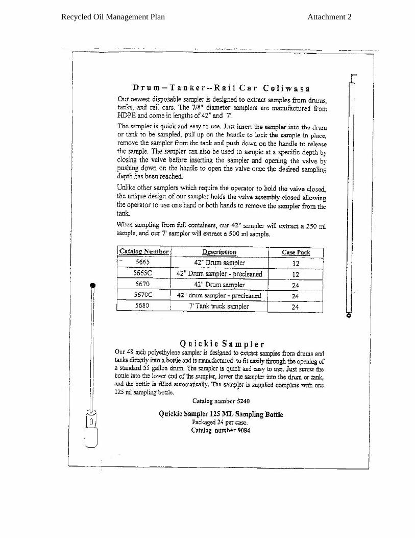
polyethylene COLIWASA (Composite Liquid Waste Sampler) and for small cans a Drum Thief
sampler is recommended (see description in Attachment 2 and additional details in 5.2 and 5.3
below).
4.4 Sample Container
Sample containers come in a variety of sizes, shapes and materials. When selecting the proper
container for a given application, one must have knowledge of the materials to be sampled to
ensure there is no interaction between the sampled material and the container, as this would
affect the sample integrity. A 1000 ml brown Nalgene bottle is recommended for all sampling
to protect potential light-sensitive materials. USE ONLY NEW BROWN NALGENE
BOTTLES. Used bottles should be discarded to prevent possible cross-contamination. Do not fill
to more than 95% of the bottle capacity. This will leave room for thermal expansion of the
sample during storage and transport.
4.5 Sample Volume
Analytical requirements essentially dictate the sample volume. However, it is always better to
have more sample than what is required for analyses. A 950 ml sample (95% capacity of a 1000
ml brown Nalgene bottle) is recommended.
Recycled Oil Management Plan Rev. 1: 08/29/01
Rev. 2: 12/9/02
21
4.6 Sample Labeling and Identification
It is imperative that the sample collected be immediately capped, labeled and adequately
identified. All samples are to be labeled immediately after collection in the field. Each
Nalgene bottle will be labeled using a "self-adhesive label" and should be additionally secured
using clear tape to prevent accidental defacing of the label. The person collecting the sample
should record the sample number on the label using the following format:
(example: Region/Date (month, day, year)/Sample Number - "WSRO/031798/01" –
Winston-Salem Region/March 17, 1998/sample 01). Inspectors collecting samples in the same
region, on the same day, should take precautions to prevent duplication of sample numbers.
Therefore, inspectors should put their initials on the label, in case two samples are accidentally
sent to the laboratory with the same number. This way it may be possible to differentiate
between samples to know who should be contacted. The date in the sample number should
always include two digits for each part (month-03, day-17, year-01).
Use the following letter designations for your respective region when assigning sample numbers:
ARO = Asheville Region
FRO = Fayetteville Region
MRO = Mooresville Region
RRO = Raleigh Region
WARO = Washington Region
WIRO = Wilmington Region
WSRO = Winston-Salem Region
RCO = Raleigh Central Office
The "Recycled Oil Sample Report" (see Attachment 3) is an important document to be
completed by DAQ personnel during each sampling event. Incomplete Recycled Oil Sample
Report forms will be returned for corrections by the regional DAQ inspector who collected the
sample. At a minimum this report shall include the following:
a. Sample number (as described above)
b. Date and time the sample was collected
c. Facility ID number (County/Prem number)
d. Name of facility sampled
e. Description of sample point (boiler feed line, tank, drum, etc.)
f. Recycled oil supplier information
g. Parameters for analysis
h. Type of recycled oil sampled (#2, #4, etc.)
i. Duplicate Sample Taken - Yes or No (signed)
j. Remarks - Describe any difficulty in sample collection,
sample condition, weather problems, etc.
k. Name of the person collecting sample(s)
l. Signature of sample collector

Recycled Oil Management Plan Rev. 1: 08/29/01
Rev. 2: 12/9/02
22
If samples are collected from more than one facility the same day, a separate "Recycled Oil
Sample Report" for each facility shall be completed and the sample number will increase
sequentially.
A copy of the "Recycled Oil Sample Report" shall be shipped along with all samples to the
Toxics Protection Branch Laboratory (see 4.7 below for the mailing address).
The "Recycled Oil Sample Report" should be accompanied with the "Chain-of-Custody" form
(see Attachment 4).
4.7 Sample Storage and Transportation
After collection, each recycled oil sample should be closed (capped) to minimize moisture and
dust contamination, effects of sun light and prevent loss of volatile organic constituents.
All samples should be sealed with a Chain-of-Custody (COC) seal and placed in the shipping
container (Pelican Case) along with a completed Recycled Oil Sample Report form and a Chain-
of-Custody form. This will ensure that chain-of-custody is maintained for each sample being
shipped.
Recycled oil samples should be shipped by Courier Mail on pre-printed labels to:
Toxics Protection Branch Laboratory
Division of Air Quality
1622 Mail Service Center
Raleigh, NC 27699-1622
COURIER #52-01-00
All recycled oil samples should be shipped within THREE workdays after collection. After
arrival at the laboratory, each sample will be aliquoted within FIVE working days and forwarded
to an appropriate analytical laboratory for analysis.
5.0 RECYCLED OIL SAMPLE COLLECTION PROGRAM
The recycled oil sampling program may require that samples be collected from a variety of
different sources and occasionally from difficult-to-reach sampling points. Therefore, details of
each and every situation cannot be included in this document, however, examples of the more
common sampling points are outlined below.
It is anticipated that most recycled oil samples will be collected from facilities burning recycled
oil in boilers, kilns, rotary dryers or furnaces. Such facilities may have recycled oil contained in
tanks, tank cars, barrels, drums, cans, etc. Consequently, sampling procedures detailed below
address these types of sources. However, upon request to the Toxocs Protection Branch,

Recycled Oil Management Plan Rev. 1: 08/29/01
Rev. 2: 12/9/02
Rev. 3: 5/5/04
23
technical details related to any other special point sources can be obtained. The procedures
included here are those that are approved and recommended by the American Society for Testing
and Materials (ASTM) {see Attachment 5, ASTM D5495-94 enclosed for additional details}.
The following sample procedures outlined here probably represent the majority of the sampling
situations that may be encountered.
5.1 Manual Burner Feedline Sampling
Feedline sampling is the preferred method since compositionally it represents the actual oil being
combusted at the time of the sample collection. Most burner fuel feed lines have a sample tap in
the line from which an oil sample can be collected. If the fuel feed line does not have a sample
tap, ask the facility personnel to have one installed for future sampling events. When sampling
from a burner fuel feed line, flush the sample tap and line until they are adequately (at minimum
two volumes of the sample tap) purged. Collect the sample into a 1000 ml brown Nalgene
bottle, cap, label and transport to the laboratory for chemical analysis of desired parameters as
listed in Table 2 (See Attachment 14 “ Standard Operating Procedure for Recycled Oil Sample
Collection”).
Caution: The fuel in these feed lines will be under pressure and may also be heated.
Therefore, take extreme care when opening the valve for sample collection.
5.2 Storage Tanks and Tank Cars
If it is not possible to collect a recycled oil sample from the fuel feed line, then it will be
necessary to collect the sample from an alternate location such as a storage tank or tank car.
Storage tanks and tank cars generally hold large volumes. These storage vessels should be
sampled by inserting an open disposable polyethylene COLIWASA, 7/8 inch diameter and 7 feet
long, into the top of the tank to a depth of approximately six inches to one foot from the bottom
This will help in avoiding the collection of water that may have settled to the bottom. Pull the
plunger on the COLIWASA to seal the end while removing the sample. Release the sample into
a sample bottle and repeat this process until the desired sample volume (950 ml) is reached.
Remember personal safety precautions should be exercised when collecting samples from
tanks or tank cars. Climbing to the top of a tank or tank car to collect samples can be risky, as
one can slip and fall. The facility should provide adequate personal protection for the safe
collection of recycled oil samples. A platform or man lift with safety handrails is the minimum
safe work area that should be used by the facility personnel during the sampling process. Details
of such sampling and/or sample locations should be described in the "Recycled Oil Sample
Report" under the sample point description. Additional disposable polyethylene COLIWASA
samplers, 7/8 inch diameter and 7 feet long, are commercially available for tank and tank car
sampling.
Recycled Oil Management Plan Rev. 1: 08/29/01
Rev. 2: 12/9/02
Rev. 3: 3/26/09
24
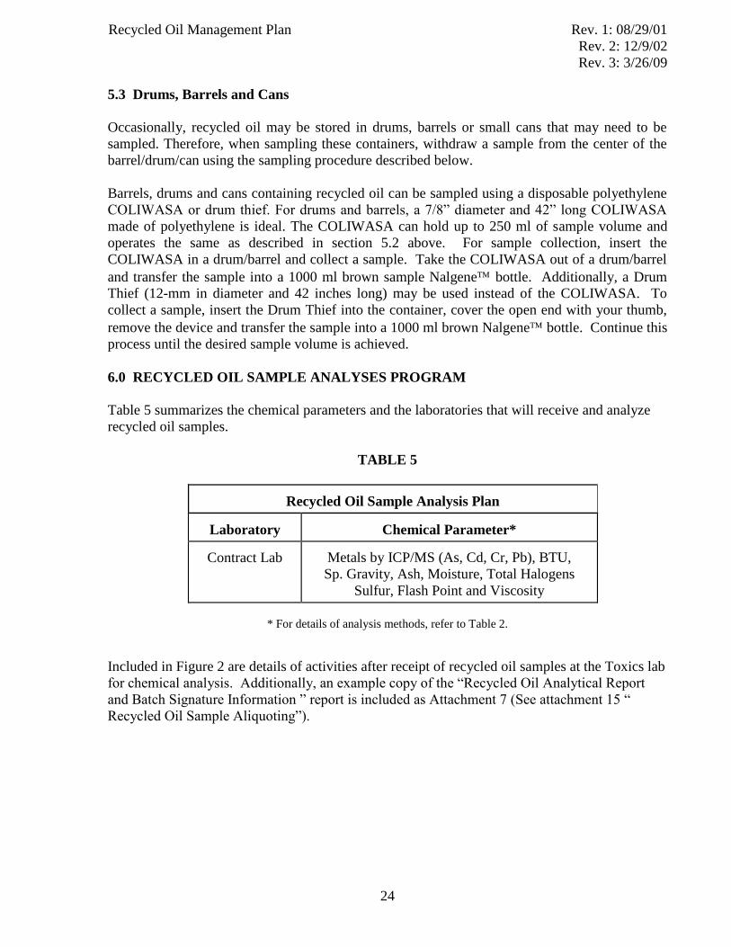
5.3 Drums, Barrels and Cans
Occasionally, recycled oil may be stored in drums, barrels or small cans that may need to be
sampled. Therefore, when sampling these containers, withdraw a sample from the center of the
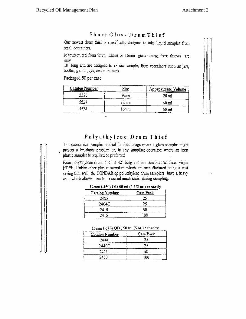
barrel/drum/can using the sampling procedure described below.
Barrels, drums and cans containing recycled oil can be sampled using a disposable polyethylene
COLIWASA or drum thief. For drums and barrels, a 7/8” diameter and 42” long COLIWASA
made of polyethylene is ideal. The COLIWASA can hold up to 250 ml of sample volume and
operates the same as described in section 5.2 above. For sample collection, insert the
COLIWASA in a drum/barrel and collect a sample. Take the COLIWASA out of a drum/barrel
and transfer the sample into a 1000 ml brown sample Nalgene bottle. Additionally, a Drum
Thief (12-mm in diameter and 42 inches long) may be used instead of the COLIWASA. To
collect a sample, insert the Drum Thief into the container, cover the open end with your thumb,
remove the device and transfer the sample into a 1000 ml brown Nalgene bottle. Continue this
process until the desired sample volume is achieved.
6.0 RECYCLED OIL SAMPLE ANALYSES PROGRAM
Table 5 summarizes the chemical parameters and the laboratories that will receive and analyze
recycled oil samples.
TABLE 5
Recycled Oil Sample Analysis Plan
Laboratory
Chemical Parameter*
Contract Lab
Metals by ICP/MS (As, Cd, Cr, Pb), BTU,
Sp. Gravity, Ash, Moisture, Total Halogens
Sulfur, Flash Point and Viscosity
* For details of analysis methods, refer to Table 2.
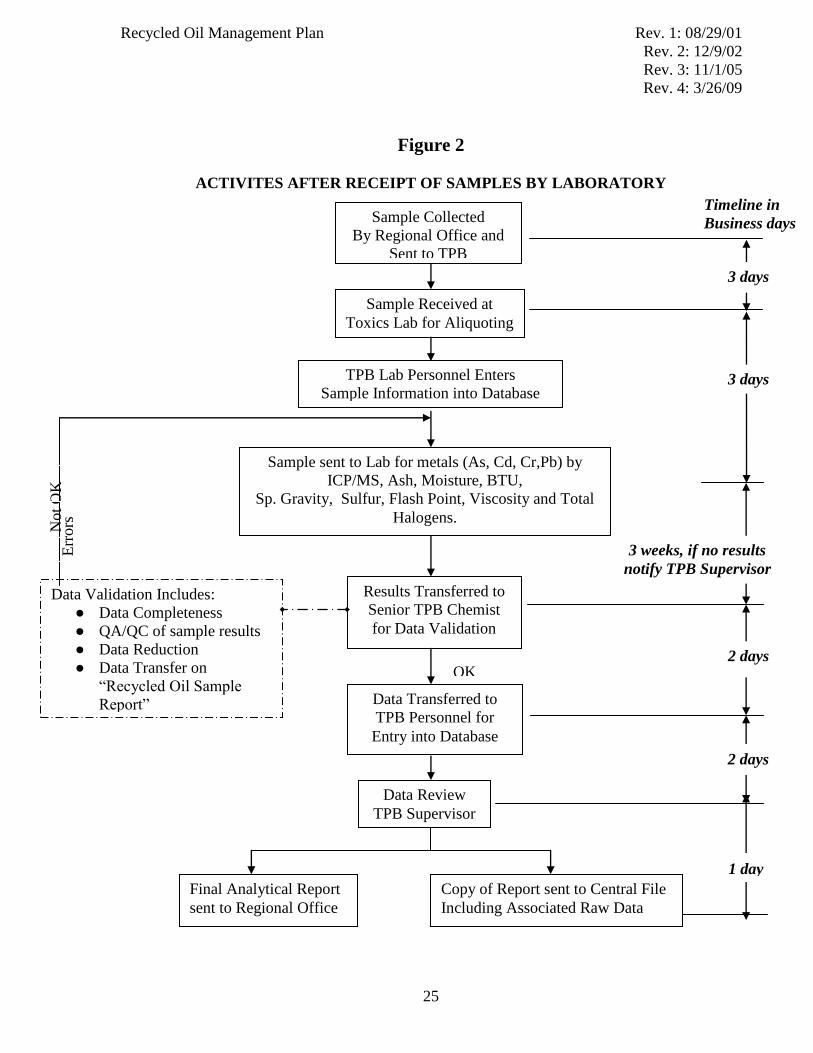
Included in Figure 2 are details of activities after receipt of recycled oil samples at the Toxics lab
for chemical analysis. Additionally, an example copy of the “Recycled Oil Analytical Report
and Batch Signature Information ” report is included as Attachment 7 (See attachment 15 “
Recycled Oil Sample Aliquoting”).
Recycled Oil Management Plan Rev. 1: 08/29/01
Rev. 2: 12/9/02
Rev. 3: 11/1/05
Rev. 4: 3/26/09
25
Figure 2
ACTIVITES AFTER RECEIPT OF SAMPLES BY LABORATORY
Timeline in
Business days Sample Collected
By Regional Office and
Sent to TPB
Sample Received at
Toxics Lab for Aliquoting
Results Transferred to
Senior TPB Chemist
for Data Validation
Data Transferred to
TPB Personnel for
Entry into Database
Data Validation Includes:
● Data Completeness
● QA/QC of sample results
● Data Reduction
● Data Transfer on
“Recycled Oil Sample
Report”
Final Analytical Report
sent to Regional Office
Copy of Report sent to Central File
Including Associated Raw Data
Data Review
TPB Supervisor
3 days
3 days TPB Lab Personnel Enters
Sample Information into Database
3 weeks, if no results
notify TPB Supervisor
2 days
2 days
1 day
Not
OK
E
rrors
OK
Sample sent to Lab for metals (As, Cd, Cr,Pb) by
ICP/MS, Ash, Moisture, BTU,
Sp. Gravity, Sulfur, Flash Point, Viscosity and Total
Halogens.
Recycled Oil Management Plan
26
REFERENCES
1. U.S. Environmental Protection Agency, Hazardous Waste Management Systems;
Identification and Listing of Hazardous Waste; Recycled Used Oil Management
Standards., Fed. Reg. 57 (176): 41566-41626., Sept. 10, 1992.
2. Mueller Associates, Waste Oil: Reclaiming Technology Utilization and Disposal., Park
Ridge, N.J. Noyes Data Corporation, 1989.
3. Byrne, J.P., C.A. Cody, P.J. Doyle, J.S. MacKinnon, A. A. Mayor, A.M. Reid, S.K
Rosner, and C. J. Talbot., Used Motor Oil in Massachusetts: A Prioritization of End Uses
Based on Human Health and Environmental Risk. Prepared for the Commonwealth of
Massachusetts-Department of Environmental Protection by Tufts University-Department
of Civil Engineering, 1989.
4. U.S. Environmental Protection Agency., Composition and Management of Used Oil
Generated in the United States., EPA/530-SW-013, Washington, D.C. 1984.
5. U.S. Environmental Protection Agency., Hazardous Waste Management System: General
Identification and Listing of Hazardous Wastes: Used Oil., Fed. Reg. 56 (184): 48000-
48074., Sept. 23, 1991.
6. U.S. Environmental Protection Agency., Environmental Regulations and Technology-
Managing Used Motor Oil, EPA/625/R-94/010, Page 3, Dec. 1994.
7. U.S. Environmental Protection Agency., Environmental Fact Sheets: Management
Standards Issued to Control Potential Risks from Recycled Used Oil-No Hazardous
Waste Listing., EPA/530-F-92-018, Washington, D.C. 1992.
Recycled Oil Management Plan
ATTACHMENTS
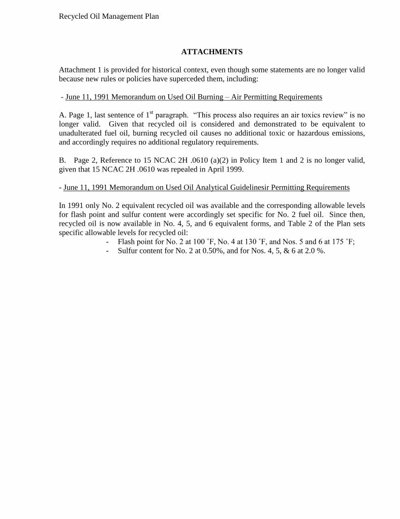
Attachment 1 is provided for historical context, even though some statements are no longer valid
because new rules or policies have superceded them, including:
- June 11, 1991 Memorandum on Used Oil Burning – Air Permitting Requirements
A. Page 1, last sentence of 1st paragraph. “This process also requires an air toxics review” is no
longer valid. Given that recycled oil is considered and demonstrated to be equivalent to
unadulterated fuel oil, burning recycled oil causes no additional toxic or hazardous emissions,
and accordingly requires no additional regulatory requirements.
B. Page 2, Reference to 15 NCAC 2H .0610 (a)(2) in Policy Item 1 and 2 is no longer valid,
given that 15 NCAC 2H .0610 was repealed in April 1999.
- June 11, 1991 Memorandum on Used Oil Analytical Guidelinesir Permitting Requirements
In 1991 only No. 2 equivalent recycled oil was available and the corresponding allowable levels
for flash point and sulfur content were accordingly set specific for No. 2 fuel oil. Since then,
recycled oil is now available in No. 4, 5, and 6 equivalent forms, and Table 2 of the Plan sets
specific allowable levels for recycled oil:
- Flash point for No. 2 at 100 ˚F, No. 4 at 130 ˚F, and Nos. 5 and 6 at 175 ˚F;
- Sulfur content for No. 2 at 0.50%, and for Nos. 4, 5, & 6 at 2.0 %.

Recycled Oil Management Plan Attachment 1

Recycled Oil Management Plan Attachment 1

Recycled Oil Management Plan Attachment 1

Recycled Oil Management Plan Attachment 1
Recycled Oil Management Plan Attachment 2
Recycled Oil Management Plan Attachment 2
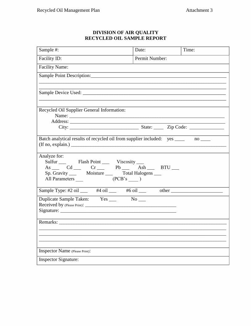
Recycled Oil Management Plan Attachment 3
DIVISION OF AIR QUALITY
RECYCLED OIL SAMPLE REPORT
Sample #: Date: Time:
Facility ID: Permit Number:
Facility Name:
Sample Point Description:_______________________________________________________
____________________________________________________________________________
____________________________________________________________________________
Sample Device Used: __________________________________________________________
____________________________________________________________________________
Recycled Oil Supplier General Information:
Name: _______________________________________________________________
Address: _______________________________________________________________
City: ____________________________ State: ____ Zip Code: ______________
Batch analytical results of recycled oil from supplier included: yes ____ no ____
(If no, explain.) _______________________________________________________________
Analyze for:
Sulfur ___ Flash Point ___ Viscosity ___
As ___ Cd ___ Cr ___ Pb ___ Ash ___ BTU ___
Sp. Gravity ___ Moisture ___ Total Halogens ___
All Parameters ___ (PCB’s ____ )
Sample Type: #2 oil ___ #4 oil ___ #6 oil ___ other _____________________
Duplicate Sample Taken: Yes ___ No ___
Received by (Please Print): _____________________________________
Signature: _______________________________________________
Remarks: ____________________________________________________________________
____________________________________________________________________________
____________________________________________________________________________
____________________________________________________________________________
Inspector Name (Please Print):
Inspector Signature:

Recycled Oil Management Plan Attachment 4

Recycled Oil Management Plan Attachment 5

Recycled Oil Management Plan Attachment 5
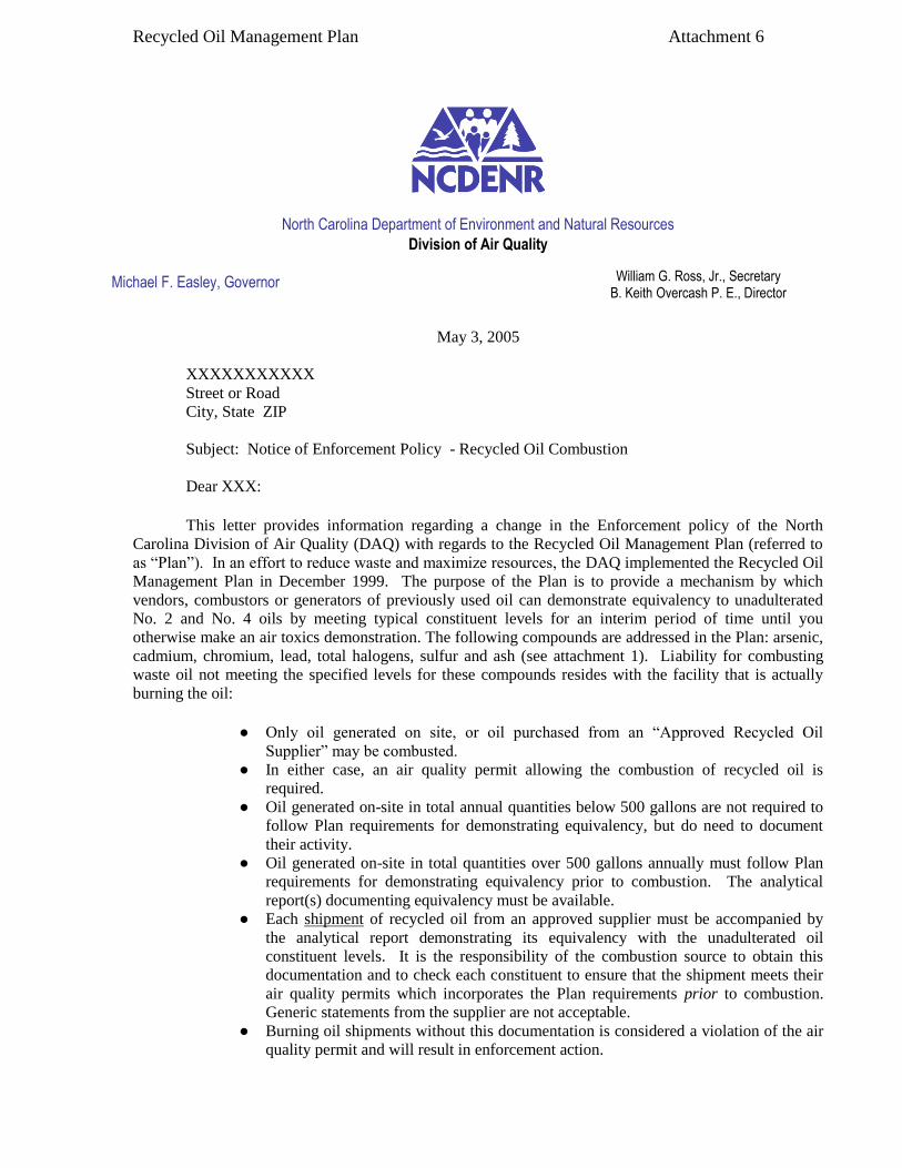
Recycled Oil Management Plan Attachment 6
North Carolina Department of Environment and Natural Resources
Division of Air Quality
Michael F. Easley, Governor
May 3, 2005
XXXXXXXXXXX
Street or Road
City, State ZIP
Subject: Notice of Enforcement Policy - Recycled Oil Combustion
Dear XXX:
This letter provides information regarding a change in the Enforcement policy of the North
Carolina Division of Air Quality (DAQ) with regards to the Recycled Oil Management Plan (referred to
as “Plan”). In an effort to reduce waste and maximize resources, the DAQ implemented the Recycled Oil
Management Plan in December 1999. The purpose of the Plan is to provide a mechanism by which
vendors, combustors or generators of previously used oil can demonstrate equivalency to unadulterated
No. 2 and No. 4 oils by meeting typical constituent levels for an interim period of time until you
otherwise make an air toxics demonstration. The following compounds are addressed in the Plan: arsenic,
cadmium, chromium, lead, total halogens, sulfur and ash (see attachment 1). Liability for combusting
waste oil not meeting the specified levels for these compounds resides with the facility that is actually
burning the oil:
● Only oil generated on site, or oil purchased from an “Approved Recycled Oil
Supplier” may be combusted.
● In either case, an air quality permit allowing the combustion of recycled oil is
required.
● Oil generated on-site in total annual quantities below 500 gallons are not required to
follow Plan requirements for demonstrating equivalency, but do need to document
their activity.
● Oil generated on-site in total quantities over 500 gallons annually must follow Plan
requirements for demonstrating equivalency prior to combustion. The analytical
report(s) documenting equivalency must be available.
● Each shipment of recycled oil from an approved supplier must be accompanied by
the analytical report demonstrating its equivalency with the unadulterated oil
constituent levels. It is the responsibility of the combustion source to obtain this
documentation and to check each constituent to ensure that the shipment meets their
air quality permits which incorporates the Plan requirements prior to combustion.
Generic statements from the supplier are not acceptable.
● Burning oil shipments without this documentation is considered a violation of the air
quality permit and will result in enforcement action.
William G. Ross, Jr., Secretary B. Keith Overcash P. E., Director

Recycled Oil Management Plan Attachment 6
● Burning oil shipments where documentation shows that equivalency has not been met
is considered a violation of the air quality permit and will result in enforcement
action.
● The DAQ periodically samples facilities combusting recycled oil and performs
laboratory analysis
Since implementation, DAQ has identified several instances where it appears that the constituent
levels had been exceeded in oil samples that were collected at facilities receiving oil from approved
vendors. In the past, DAQ’s procedures were to collect a second sample from these same facilities within
one year decisions regarding enforcement action were then made based on the subsequent sample. This
will no longer be the procedure. Now, during the DAQ audit, when an oil sample is identified as not
meeting the equivalency criteria as specified in your air quality permit, a NOTICE of VIOLATION will
be issued to the facility combusting the oil even if the approved supplier has provided you an analysis,
which indicates that the recycled oil shipment was in compliance with the unadulterated oil specifications.
It should be noted that all audit samples will be collected as close as possible to the burner.
In addition to sampling combustion sources, the DAQ will begin collecting inspection samples
from the Approved Recycled Oil Suppliers. Oil samples that fail the audit may result in revocation of a
supplier’s approval. Additionally, the DAQ is evaluating the feasibility of a rule change, which may
make it illegal in North Carolina to supply recycled oil not meeting specific criteria. In the interim,
facilities combusting recycled oil contrary to the terms and conditions of their air permits will be held
solely liable for violating North Carolina’s Air Quality Rules. Please discuss this issue with your
recycled oil supplier and take all steps necessary to avoid potential violations at your facility. One step
you may wish to consider is to install car-seals or similar "lock-out/tag-out" devices on the waste oil tank
fill and retain records that indicate when the seal is broken. Each broken seal event should reference a
particular delivery and that delivery’s supplier analysis. Should you have questions regarding this matter,
please contact the Compliance Coordinator in your regional DAQ office.
Sincerely,
Lee A. Daniel, Chief
Technical Services Section
CC: Regional Supervisors
Regional Compliance Coordinators

Recycled Oil Management Plan Attachment 7
Example Form of Recycled Oil Analytical Report and Batch Signature Information
FACILITY NAME _____________________________________FACILITY CITY ______________________________
FACILITY COUNTY _________________________________ FUEL OIL NUMBER ____________________________
VENDOR/PROCESSOR NAME __________________________SAMPLE NUMBER _____________________________
PCB CERTIFICATION ATTACHED: ___________________ BATCH NUMBER: _____________________________
BATCH VOLUME (GAL) ______________________________ PROCESSING TANK NUMBER: __________________
DATE /TIME BATCH COMPLETED TREATEMENT: ______________________________________________________
RECYCLED OIL VOLUME DELIVERED TO FACILITY (GAL): _____________________________________________
DATE /TIME OF DELIVERY TO FACILITY: __________________________________________________________
NC RECYCLED OIL
PARAMETER LIMIT 1 SAMPLE CONCENTRATION2
ARSENIC (ppmw) 1.0 . . . . . . . . . . . . . . . . . . . . . . . . . . . . . . _____________
CADMIUM ppmw) 2.0 . . . . . . . . . . . . . . . . . . . . . . . . . . . . . . _____________
CHROMIUM (ppmw) 5.0 . . . . . . . . . . . . . . . . . . . . . . . . . . . . . . _____________
LEAD (ppmw) 100 . . . . . . . . . . . . . . . . . . . . . . . . . . . . … . _____________
TOTAL HALOGENS (ppmw) 1000 . . . . . . . . . . . . . . . . . . . . . . . . . . . . . . . ______________
SULFUR (%weight basis)
- No. 2 0.50 . . . . . . . . . . . . . . . . . . . . . . . . . . . . . . .. ______________
- No. 4, 5, or 6 2.0 . . . . . . . . . . . . . . . . . . . . . . . . . . . . . .. ______________
ASH (%weight basis) 1.0 . . . . . . . . . . . . . . . . . . . . . . . . . . . . . ______________
FLASH POINT (ºF) (Minimim)
- No. 2 100 . . . . . . . . . . . . . . . . . . . . . . . . . . . . . . .. ______________
- No. 4 130 . . . . . . . . . . . . . . . . . . . . . . . . . . . . . . .. ______________
- No. 5 or 6 175 . . . . . . . . . . . . . . . . . . . . . . . . . . . . . . .. ______________
___________________________________________________________
1 = Maximum limits as per North Carolina Air Toxics regulations, except where specified as minimum
limits. Limits on Parameter 1 – 7 are on a weight basis.
2 = Analyte concentration expressed as ppmw or micrograms per gram), wt/wt, of sample.
Notes: ________________________________________________________________
Form Prepared By: _____________________________________________________

Recycled Oil Management Plan Attachment 8
NORTH CAROLINA
APPROVED LIST OF RECYCLED OIL SUPPLIERS
as of
January 28, 2013
Company
Grade Approved Date Re-Certified Date
Enterprise Oil
5201 N. Middlebrook Pike
Knoxville, Tennessee 37921
Contact: Charles Alexander
Phone: (800) 875-3860 or
(865) 558-0533
No. 4
12/95
11/18/2009
Holston Group, Inc.
19119 Great Smoky Mt. Expressway
Waynesville, North Carolina 28786
Contact: Roger Wilson
Phone: (800) 222-4530
No.2
No. 4
10/93
4/28/2009
Necessary Oil Company
1300 Georgia Ave.
Bristol, Tennessee 37620
Contact: Joe Byington
Phone: (423) 764-4533
No. 4
12/94
11/17/2009
Noble Oil Services, Inc.
5617 Clyde Rhyne Drive
Sanford, North Carolina 27330
Contact: Jim Noble
Phone: (919) 774-8180
No. 2
6/91
1/2009
Noble Oil Services, Inc.
5617 Clyde Rhyne Drive
Sanford, North Carolina 27330
Contact: Jim Noble
Phone: (919) 774-8180
No. 4
6/99
1/2009
Safety-Kleen System Inc.
12040 Goodrich Drive
Charlotte, North Carolina 28273
Contact: Richard Stout
Phone: (704) 201-2002
E-mail: [email protected]
No. 4
3/97
6/23/2009

Recycled Oil Management Plan Attachment 8
Company
Grade Approved Date Re-Certified Date
Safety-Kleen System Inc.
12040 Goodrich Drive
Charlotte, North Carolina 28273
Contact: Richard Stout
Phone: (704) 201-2002
E-mail: [email protected]
No. 2
12/08/98
6/23/2009
Safety-Kleen System Inc.
2760 Valley View Drive
Shreveport, Louisiana 71108
Contact: Brian Dick
Phone: (318) 688-1191
No.4
7/3/02
6/23/2009
FCC Environmental
2115 Speedrail Court
Concord, North Carolina 28025
Contact: Bill Henkel
Phone: (704) 455-1333 x 24
No. 2
No. 4
5/93
7/14/2009
FCC Environmental
5800 Farrington Avenue
Alexandria, Virginia 22304-4893
Contact: Drew Frye
Phone: (800) 673-8521 or
(703) 370-7306
FAX: (703) 370-8067
No. 4
1/16/98
7/14/2009
Shamrock Environmental Corporation
P.O. Box 14987
Greensboro, North Carolina 27415
Contact: Jim Hollingsworth
Phone: (336) 375-1989
FAX: (336) 375-1801
No. 4
7/3/02
8/2009
Universal Environmental Services, LLC
411 Dividend Drive
Peachtree City, Georgia 30269
Contact: Donald Golden
Phone: (770) 486-8816
FAX: (770) 486-0616
E-mail:
No. 2
12/17/04
11/2009

Recycled Oil Management Plan Attachment 8
Company Grade Approved Date Re-Certified Date
Advanced Oil
1257 Henrico Road
Conley, Georgia 30288-1005
Contact: Laurie Whittington
Phone: (404) 361-3811
FAX (404) 361-1788
No. 4
5/31/05
10/2009
FCC Environmental
2353 Lanier Road
Rockville, Virginia 23146
Contact: Ron Heath
Phone: (804) 749-8344x205
FAX: (804) 749-8450
No. 4
5/29/08
FCC Environmental
5539 Faris Street
Norfolk, Virginia 23531
Contact: Rob Helgeson
Phone: (757) 852-9142
FAX: (757) 852 – 9246
No. 4
5/29/08
VLS Recovery Service
305 South Main Street
Mauldin, SC 29662
Contact: Platt Moore
Phone:(864) 962-9953 Ext 314
FAX: (864) 679-3703
E-mail: [email protected]
No.4
12/03/08
Coastal Refining Corporation
2830 Tremont Road
Savannah, Georgia 31405
Contact: Richard L. Glendye, Jr.
Phone: (912) 233-9999
FAX: (912) 236-4162
No.5
1/23/2009
HAZ-MAT Environmental Services
221 Dalton Avenue
Charlotte, NC 28206
Contact: Neil Danziger-
Phone: (704) 332-5600
FAX :(704) 375-7183
E-mail: [email protected]
No.2
No.4
5/6/2009

Recycled Oil Management Plan Attachment 8
Company Grade Approved Date Re-Certified Date
Sully’s Oil Recovery
10518 Royster Road NE
Post Office Box 656
Leland, North Carolina 28451
Contact: Scott Sutherland
Phone:(910) 371-5792
No. 2
12/04/2012

Recycled Oil Management Plan Attachment 9
Note, for No. 4 fuel oil, the minimum flash point is 135°F, and a maximum 2.0 % S.
Note, for No. 5 or 6 fuel, the minimum flash point is 175°F, and a maximum 2.0 % S.
The latest recycled oil stipulation:

Recycled Oil Management Plan Attachment 9
Sulfur 0.5% maximum (by weight)

Recycled Oil Management Plan Attachment 10
NCDENR North Carolina Department of Environment and Natural Resources
Division of Air Quality
Michael F. Easley, Governor William G. Ross, Jr., Secretary B. Keith Overcash, P.E., Director
May 28, 2004
MEMORANDUM
To: DAQ Section Chiefs
DAQ Regional Supervisors
From: Keith Overcash, P.E.
Subject: On-site Generated Waste Oil Combustion
The DAQ currently has in place procedures that allow sources in North Carolina to burn
waste oils which have been deemed "unadulterated". These waste oil procedures were
designed to address large to medium sized shipments of waste oil by suppliers, like Noble Oil
Services, to manufacturing sites for use as fuel. The requirements set up under this procedure
include relatively frequent and complex sampling and monitoring. Such requirements are
reasonable for sources that burn large quantities of this product because when a facility bums
large quantities of waste oil a potential for increased toxic air pollutant (TAP) emissions exists if
the product cannot be ensured to be equivalent to unadulterated fuels.
On the other hand, the current procedure does not address small quantities of waste oil
such as those generated by on-site mechanical activities. When dealing with such smaller
quantities, the risk should be reduced and, therefore, the resulting regulatory regime governing
such activity can in most cases be safely mitigated. This is because the amount of waste oils
generated and burned are minimal as compared with the total quantity of fuel typically
burned at these facilities. From an environmental viewpoint, the dilution of the on-site waste oil
with a small amount of virgin fuel will quickly reduce the level of TAPs emitted to well below the
specifications we have developed to define unadulterated recycled waste oil. Additionally, in
the case of waste oil suppliers like Noble Oil, the product that is burned is a conglomeration of
oils collected from various locations and applications. In contrast, where a source burns
relatively small amounts of a waste oil generated from known and limited on-site sources, the
risk of contamination and adverse environmental impact is greatly reduced.
Based on these considerations, sources burning lesser quantities of on-site generated
waste oil should be able to do so through a second tier permitting approach. Using this
approach, the source is not required to obtain an air permit to burn on-site generated waste oil
provided not more than 500 gallons are burned in any single year.
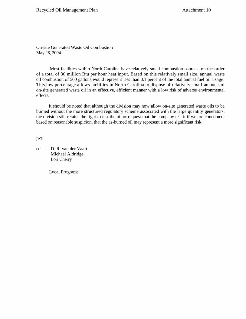
Recycled Oil Management Plan Attachment 10
On-site Generated Waste Oil Combustion
May 28, 2004
Most facilities within North Carolina have relatively small combustion sources, on the order
of a total of 30 million Btu per hour heat input. Based on this relatively small size, annual waste
oil combustion of 500 gallons would represent less than 0.1 percent of the total annual fuel oil usage.
This low percentage allows facilities in North Carolina to dispose of relatively small amounts of
on-site generated waste oil in an effective, efficient manner with a low risk of adverse environmental
effects.
It should be noted that although the division may now allow on-site generated waste oils to be
burned without the more structured regulatory scheme associated with the large quantity generators,
the division still retains the right to test the oil or request that the company test it if we are concerned,
based on reasonable suspicion, that the as-burned oil may represent a more significant risk.
jwe
cc: D. R. van der Vaart
Michael Aldridge
Lori Cherry
Local Programs

Recycled Oil Management Plan Attachment 11
METHOD 3052
MICROWAVE ASSISTED ACID DIGESTION OF SILICEOUS AND
ORGANICALLY BASED MATRICES
1.0 SCOPE AND APPLICATION 1.1 This method is applicable to the microwave assisted acid digestion of siliceous matrices, and organic matrices and other complex matrices. If a total decomposition analysis (relative to the target analyte list) is required, the following matrices can be digested: ashes, biological tissues, oils, oil contaminated soils, sediments, sludges, and soils. This method is applicable for the following elements:
Aluminum Cadmium Iron Molybdenum Sodium Antimony Calcium Lead Nickel Strontium Arsenic Chromium Magnesium Potassium Thallium Boron Cobalt Manganese Selenium Vanadium Barium Copper Mercury Silver Zinc Beryllium
Other elements and matrices may be analyzed by this method if performance is demonstrated for the analyte of interest, in the matrices of interest, at the concentration levels of interest (see Sec.8.0). Note: This technique is not appropriate for regulatory applications that require the use of leachate preparations (i.e., Method 3050, Method 3051, Method 1311, Method 1312, Method 1310, Method 1320, Method 1330, Method 3031, Method 3040). This method is appropriate for those applications requiring a total decomposition for research purposes (i.e., geological studies, mass balances, analysis of Standard Reference Materials) or in response to a regulation that requires total sample decomposition. 1.2 This method is provided as a rapid multi-element, microwave assisted acid digestion prior to analysis protocol so that decisions can be made about the site or material. Digests and alternative procedures produced by the method are suitable for analysis by flame atomic absorption spectrometry (FLAA), cold vapor atomic absorption spectrometry (CVAA), graphite furnace atomic absorption spectrometry (GFAA), inductively coupled plasma atomic emission spectrometry (ICPAES),inductively coupled plasma mass spectrometry (ICP-MS) and other analytical elemental analysis techniques where applicable. Due to the rapid advances in microwave technology, consult your manufacturer's recommended instructions for guidance on their microwave digestion system and refer to this manual’s "Disclaimer" when conducting analyses using Method 3052. 1.3 The goal of this method is total sample decomposition and with judicious choice of acid combinations this is achievable for most matrices (see Sec. 3.2). Selection of reagents which give the highest recoveries for the target analytes is considered the optimum method condition.
CD-ROM 3052 - 1 Revision 0 December 1996

Recycled Oil Management Plan Attachment 11
2.0 SUMMARY OF METHOD 2.1 A representative sample of up to 0.5 g is digested in 9 mL of concentrated nitric acid and usually 3 mL hydrofluoric acid for 15 minutes using microwave heating with a suitable laboratory microwave system. The method has several additional alternative acid and reagent combinations including hydrochloric acid and hydrogen peroxide. The method has provisions for scaling up the sample size to a maximum of 1.0 g. The sample and acid are placed in suitably inert polymeric microwave vessels. The vessel is sealed and heated in the microwave system. The temperature profile is specified to permit specific reactions and incorporates reaching 180 ± 5 ºC in approximately less than 5.5 minutes and remaining at 180 ± 5 ºC for 9.5 minutes for the completion of specific reactions (Ref. 1, 2, 3, 4). After cooling, the vessel contents may be filtered, centrifuged, or allowed to settle and then decanted, diluted to volume, and analyzed by the appropriate SW-846 method. 3.0 INTERFERENCES 3.1 Gaseous digestion reaction products, very reactive, or volatile materials that may create high pressures when heated and may cause venting of the vessels with potential loss of sample and analytes. The complete decomposition of either carbonates, or carbon based samples,may cause enough pressure to vent the vessel if the sample size is greater than 0.25 g. Variations of the method due to very reactive materials are specifically addressed in sections 7.3.4 and 7.3.6.1. 3.2 Most samples will be totally dissolved by this method with judicious choice of the acid combinations. A few refractory sample matrix compounds, such as TiO2, alumina, and other oxides may not be totally dissolved and in some cases may sequester target analyte elements. 3.3 The use of several digestion reagents that are necessary to either completely decompose the matrix or to stabilize specific elements may limit the use of specific analytical instrumentation methods. Hydrochloric acid is known to interfere with some instrumental analysis methods such as flame atomic absorption (FLAA) and inductively coupled plasma atomic emission spectrometry (ICP-AES). The presence of hydrochloric acid may be problematic for graphite furnace atomic absorption (GFAA) and inductively coupled plasma mass spectrometry (ICP-MS). Hydrofluoric acid, which is capable of dissolving silicates, may require the removal of excess hydrofluoric acid or the use of specialized non-glass components during instrumental analysis. Method 3052 enables the analyst to select other decomposition reagents that may also cause problems with instrumental analyses necessitating matrix matching of standards to account for viscosity and chemical differences. 4.0 APPARATUS AND MATERIALS
4.1 Microwave apparatus requirements. 4.1.1 The temperature performance requirements necessitate the microwave decomposition system sense the temperature to within ± 2.5EC and automatically adjust the microwave field output power within 2 seconds of sensing. Temperature sensors should be accurate to ± 2EC (including the final reaction temperature of 180EC). Temperature feedback control provides the primary control performance mechanism for the method. Due to the flexibility in the reagents used to achieve total analysis, tempertuare feedback control is necessary for reproducible microwave heating.

Recycled Oil Management Plan Attachment 11
Alternatively, for a specific set of reagent(s) combination(s), quantity, and specific vessel type, a calibration control mechanism can be developed similar to previous microwave methods (see Method 3051). Through calibration of the microwave power, vessel load and heat loss, the reaction temperature profile described in Section 7.3.6 can be reproduced. The calibration settings are specific for the number and type of vessel used and for the microwave system in addition to the variation in reagent combinations. Therefore no specific calibration settings are provided in this method. These settings may be developed by using temperature monitoring equipment for each specific set of equipment and reagent combination. They may only be used if not altered as previously described in other methods such as 3051 and 3015. In this circumstance, the microwave system provides programmable power which can be programmed to within ± 12 W of the required power.Typical systems provide a nominal 600 W to 1200 W of power (Ref. 1, 2, 5). Calibration control provides backward compatibility with older laboratory microwave systems without temperature monitoring or feedback control and with lower cost microwave systems for some repetitive analyses. Older lower pressure vessels may not be compatible.
4.1.2 The temperature measurement system should be periodically calibrated at an elevated temperature. Pour silicon oil (a high temperature oil into a beaker and adequately stirred to ensure a homogeneous temperature. Place the microwave temperature sensor and a calibrated external temperature measurement sensor into the beaker. Heat the beaker to a constant temperature of 180 ± 5°C. Measure the temperature with both sensors. If the measured temperatures vary by more than 1 - 2°C, the microwave temperature measurement system needs to be calibrated. Consult the microwave manufacturer’s instructions about the specific temperature sensor calibration procedure. CAUTION: The use of microwave equipment with temperature feedback control is required to control the unfamiliar reactions of unique or untested reagent combinations of unknown samples. These tests may require additional vessel requirements such as increased pressure capabilities. 4.1.3 The microwave unit cavity is corrosion resistant and well ventilated. All electronics are protected against corrosion for safe operation. CAUTION: There are many safety and operational recommendations specific to the model and manufacturer of the microwave equipment used in individual laboratories. A listing of these specific suggestions is beyond the scope of this method and require the analyst to consult the specific equipment manual, manufacturer, and literature for proper and safe operation of the microwave equipment and vessels. 4.1.4 The method requires essentially microwave transparent and reagent resistant suitably inert polymeric materials (examples are PFA or TFM suitably inert polymeric polymers) to contain acids and samples. For higher pressure capabilities the vessel may be contained within layers of different microwave transparent materials for strength, durability, and safety. The vessels internal volume should be at least 45 mL, capable of withstanding pressures of at least 30 atm (30 bar or 435 psi), and capable of controlled pressure relief. These specifications are to provide an appropriate, safe, and durable reaction vessel of which there are many adequate designs by many suppliers.

Recycled Oil Management Plan Attachment 11
CAUTION: The outer layers of vessels are frequently not as acid or reagent resistant as the liner material and must not be chemically degraded or physically damaged to retain the performance and safety required. Routine examination of the vessel materials may be required to ensure their safe use. CAUTION: The second safety concern relates to the use of sealed containers without pressure relief devices. Temperature is the important variable controlling the reaction. Pressure is needed to attain elevated temperatures, but must be safely contained. However, many digestion vessels constructed from certain suitably inert polymerics may crack, burst, or explode in the unit under certain pressures. Only suitably inert polymeric (such as PFA or TFM and others) containers with pressure relief mechanisms or containers with suitably inert polymeric liners and pressure relief mechanisms are considered acceptable. Users are therefore advised not to use domestic (kitchen) type microwave ovens or to use inappropriate sealed containers without pressure relief for microwave acid digestions by this method. Use of laboratory-grade microwave equipment is required to prevent safety hazards. For further details, consult Reference 3 and 6. 4.1.5 A rotating turntable is employed to insure homogeneous distribution of microwave radiation within most systems (Ref. 1). The speed of the turntable should be a minimum of 3 rpm. CAUTION: Laboratories should not use domestic (kitchen) type microwave ovens for this method. There are several significant safety issues. First, when an acid such as nitric is used to effect sample digestion in microwave units in open vessel(s), or sealed vessels equipment, there is the potential for the acid gas vapor released to corrode the safety devices that prevent the microwave magnetron from shutting off when the door is opened. This can result in operator exposure to microwave energy. Use of a system with isolated and corrosion resistant safety devices prevents this from occurring. 4.2 Volumetric ware, volumetric flasks, and graduated cylinders, 50 and 100 mL capacity or equivalent. 4.3 Filter paper, qualitative or equivalent. 4.4 Filter funnel, polypropylene, polyethylene or equivalent. 4.5 Analytical balance, of appropriate capacity, with a ± 0.0001 g or appropriate precision for the weighing of the sample. Optionally, the vessel with sample and reagents may be weighed, with an appropriate precision balance, before and after microwave processing to evaluate the seal integrity in some vessel types.
CD-ROM 3052 - 4 Revision 0 December 1996

Recycled Oil Management Plan Attachment 11
5.0 REAGENTS 5.1 All reagents should be of appropriate purity or high purity (acids for example, should be sub-boiling distilled where possible) to minimize the blank levels due to elemental contamination. All references to water in the method refer to reagent water (Ref. 7). Other reagent grades may be used, provided it is first ascertained that the reagent is of sufficient purity to permit its use without lessening the accuracy of the determination. If the purity of a reagent is questionable, analyze the reagent to determine the level of impurities. The reagent blank must be less than the MDL in order to be used. 6.0 SAMPLE COLLECTION, PRESERVATION, AND HANDLING 6.1 All samples must have been collected using a sampling plan that addresses the considerations discussed in Chapter Nine of this manual. 6.2 All sample containers must be prewashed with detergents, acids, and water. Plastic and glass containers are both suitable. See Chapter Three, Sec. 3.1.3 of this manual, for further information. 6.3 Refer to Chapter Three for the appropriate holding times and storage conditions. 7.0 PROCEDURE 7.1 Temperature control of closed vessel microwave instruments provides the main feedback control performance mechanism for the method. Control requires a temperature sensor in one or more vessels during the entire decomposition. The microwave decomposition system should sense the temperature to within ± 2.5 C and permit adjustment of the microwave output power within 2 seconds. 7.2 All digestion vessels and volumetric ware must be carefully acid washed and rinsed with reagent water. When switching between high concentration samples and low concentration samples, all digestion vessels (fluoropolymer liners only) should be cleaned by leaching with hot (1:1) hydrochloric acid (greater than 80 C, but less than boiling) for a minimum of two hours followed with o hot (1:1) nitric acid (greater than 80 C, but less than boiling) for a minimum of two hours and rinsed o with reagent water and dried in a clean environment. This cleaning procedure should also be used whenever the prior use of the digestion vessels is unknown or cross contamination from vessels is suspected. Polymeric or glass volumetric ware (not used with HF) and storage containers should be cleaned by leaching with more dilute acids (approximately 10% V/V) appropriate for the specific plastics used and then rinsed with reagent water and dried in a clean environment. To avoid precipitation of silver, ensure that all HCl has been rinsed from the vessels. 7.3 Sample Digestion 7.3.1 Weigh a well-mixed sample to the nearest 0.001 g into an appropriate vessel equipped with a pressure relief mechanism. For soils, ash, sediments, sludges, and siliceous wastes, initially use no more than 0.5 g. For oil or oil contaminated soils, initially use no more than 0.25 g.
CD-ROM 3052 - 5 Revision 0 December 1996
Recycled Oil Management Plan Attachment 11
7.3.2 Add 9 ± 0.1 mL concentrated nitric acid and 3 ± 0.1 mL concentrated hydrofluoric acid to the vessel in a fume hood. If the approximate silicon dioxide content of the sample is known, the quantity of hydrofluoric acid may be varied from 0 to 5 mL for stoichiometric reasons. Samples with higher concentrations of silicon dioxide (> 70%) may require higher concentrations of hydrofluoric acid (>3 mL HF). Alternatively samples with lower concentrations of silicon dioxide (< 10% to 0%) may require much less hydrofluoric acid (0.5 mL to 0 mL). Examples are presented in Table 1, 2, 3, and 6. Acid digestion reagent combinations used in the analysis of several matrices, listed in Table 7, provide guidance for the development of new matrix decomposition procedures. 7.3.3 The addition of other reagents with the original acids prior to digestion may permit more complete oxidation of organic sample constituents, address specific decomposition chemistry requirements, or address specific elemental stability and solubility problems. The addition of 2 ± 2 mL concentrated hydrochloric acid to the nitric and hydrofluoric acids is appropriate for the stabilization of Ag, Ba, and Sb and high concentrations of Fe and Al in solution. The amount of HCl needed will vary depending on the matrix and the concentration of the analytes. The addition of hydrochloric acid may; however, limit the techniques or increase the difficulties of analysis. Examples are presented in Table 4. The addition of hydrogen peroxide (30%) in small or catalytic quantities (such as 0.1 to 2 mL) may aid in the complete oxidation of organic matter. The addition of water (double deionized) may (0 to 5 mL) improve the solubility of minerals and prevent temperature spikes due to exothermic reactions. NOTE: Supporting documentation for the chemistry of this method has been prepared in chapters 2 and 3 of reference 3. It provides additional guidance and documentation of appropriate reagent, matrix and analyte combinations that can be employed in this method. CAUTION: Only one acid mixture or quantity may be used in a single batch in the microwave to insure consistent reaction conditions between all vessels and monitored conditions. This limitation is due to the current practice of monitoring a representative vessel and applying a uniform microwave field to reproduce these reaction conditions within a group of vessels being simultaneously heated. CAUTION: Toxic nitrogen oxide(s), hydrogen fluoride, and toxic chlorine (from the addition of hydrochloric acid) fumes are usually produced during digestion. Therefore, all steps involving open or the opening of microwave vessels must be performed in a properly operating fume ventilation system. CAUTION: The analyst should wear protective gloves and face protection and must not at any time permit a solution containing hydrofluoric acid to come in contact with skin or lungs.
CD-ROM 3052 - 6 Revision 0 December 1996

Recycled Oil Management Plan Attachment 11
CAUTION: The addition of hydrochloric acid must be from concentrated hydrochloric acid and not from a premixed combination of acids as a buildup of toxic chlorine and possibly other gases will result from a premixed acid solution. This will over pressurize the vessel due to the release of these gases from solution upon heating. The gas effect is greatly lessened by following this suggestion. CAUTION: When digesting samples containing volatile or easily oxidized organic compounds, initially weigh no more than 0.10 g and observe the reaction before capping the vessel. If a vigorous reaction occurs, allow the reaction to cease before capping the vessel. If no appreciable reaction occurs, a sample weight up to 0.25 g can be used. CAUTION: The addition of hydrogen peroxide should only be done when the reactive components of the sample are known. Hydrogen peroxide may react rapidly and violently on easily oxidizable materials and should not be added if the sample may contain large quantities of easily oxidizable organic constituents. 7.3.4 The analyst should be aware of the potential for a vigorous reaction. If a vigorous reaction occurs upon the initial addition of reagent or the sample is suspected of containing easily oxidizable materials, allow the sample to predigest in the uncapped digestion vessel. Heat may be added in this step for safety considerations (for example the rapid release of carbon dioxide from carbonates, easily oxidized organic matter, etc.). Once the initial reaction has ceased, the sample may continue through the digestion procedure. 7.3.5 Seal the vessel according to the manufacturer's directions. Properly place the vessel in the microwave system according to the manufacturer's recommended specifications and connect appropriate temperature and pressure sensors to vessels according to manufacturer’s specifications. 7.3.6 This method is a performance based method, designed to achieve or approach total decomposition of the sample through achieving specific reaction conditions. The temperature of each sample should rise to 180 ± 5 ºC in approximately 5.5 minutes and remain at 180 ± 5 ºC for 9.5 minutes. The temperature-time and pressure-time profile are given for a standard soil sample in Figure 1. The number of samples simultaneously digested is dependent on the analyst. The number may range from 1 to the maximum number of vessels that the microwave units magnetron can heat according to the manufacturer’s or literature specifications (the number will depend on the power of the unit, the quantity and combination of reagents, and the heat loss from the vessels). The pressure should peak between 5 and 15 minutes for most samples (Ref. 2, 3, 5). If the pressure exceeds the pressure limits of the vessel, the pressure will be reduced by the relief mechanism of the vessel. The total decomposition of some components of a matrix may require or the reaction kinetics are dramatically improved with higher reaction temperatures. If microwave digestion systems and/or vessels are capable of achieving higher temperatures and pressures, the minimum digestion time of 9.5 minutes at a temperature of at least 180 ± 5°C is an appropriate
CD-ROM 3052 - 7 Revision 0 December 1996

Recycled Oil Management Plan Attachment 11
alternative. This change will permit the use of pressure systems if the analysis verifies that 180°C is the minimum temperature maintained by these control systems. 7.3.6.1 For reactive substances, the heating profile may be altered for safety purposes. The decomposition is primarily controlled by maintaining the reagents at 180 ± 5°C for 9.5 minutes, therefore the time it takes to heat the samples to 180 ± 5°C is not critical. The samples may be heated at a slower rate to prevent potential uncontrollable exothermic reactions. The time to reach 180 ± 5 ºC may be increased to 10 minutes provided that 180 ± 5 ºC is subsequently maintained for 9.5 minutes. Decomposition profiles are presented in Figures 1 and 2. The extreme difference in pressure is due to the gaseous digestion products. 7.3.6.2 Calibration control is applicable in reproducing this method provided the power in watts versus time parameters are determined to reproduce the specifications listed in 7.3.6. The calibration settings will be specific to the quantity and combination of reagents, quantity of vessels, and heat loss characteristics of the vessels (Ref 1). If calibration control is being used, any vessels containing acids for analytical blank purposes are counted as sample vessels and when fewer than the recommended number of samples are to be digested, the remaining vessels should be filled with the same acid mixture to achieve the full complement of vessels. This provides an energy balance, since the microwave power absorbed is proportional to the total absorbed mass in the cavity (Ref. 1). Irradiate each group of vessels using the predetermined calibration settings. (Different vessel types should not be mixed). 7.3.6.3 Pressure control for a specific matrix is applicable if instrument conditions are established using temperature control. Because each matrix will have a different reaction profile, performance using temperature control must be developed for every specific matrix type prior to use of the pressure control system. 7.3.7 At the end of the microwave program, allow the vessels to cool for a minimum of 5 minutes before removing them from the microwave system. When the vessels have cooled to near room temperature, determine if the microwave vessels have maintained a seal throughout the digestion. Due to the wide variability of vessel designs, a single procedure is not appropriate. For vessels that are sealed as discrete separate entities, the vessel weight may be taken before and after digestion to evaluate seal integrity. If the weight loss of sample exceeds 1% of the weight of the sample and reagents, then the sample is considered compromised. For vessels with burst disks, a careful visual inspection of the disk may identify compromised vessels. For vessels with resealing pressure relief mechanisms, an auditory or sometimes a physical sign indicates a vessel has vented. 7.3.8 Complete the preparation of the sample by carefully uncapping and venting each vessel in a fume hood. Vent the vessels using the procedure recommended by the vessel manufacturer. Transfer the sample to an acid-cleaned bottle. If the digested sample contains particulates which may clog nebulizers or interfere with injection of the sample into the instrument, the sample may be centrifuged, allowed to settle, or filtered.
CD-ROM 3052 - 8 Revision 0 December 1996

Recycled Oil Management Plan Attachment 11
7.3.8.1 Centrifugation: Centrifugation at 2,000 - 3,000 rpm for 10 minutes is usually sufficient to clear the supernatant. 7.3.8.2 Settling: If undissolved material remains such as TiO , or 2 other refractory oxides, allow the sample to stand until the supernatant is clear. Allowing a sample to stand overnight will usually accomplish this. If it does not, centrifuge or filter the sample. 7.3.8.3 Filtering: If necessary, the filtering apparatus must be thoroughly cleaned and prerinsed with dilute (approximately 10% V/V) nitric acid. Filter the sample through qualitative filter paper into a second acid-cleaned container. 7.3.9 If the hydrofluoric acid concentration is a consideration in the analysis technique such as with ICP methods, boric acid may be added to permit the complexation of fluoride to protect the quartz plasma torch. The amount of acid added may be varied, depending on the equipment and the analysis procedure. If this option is used, alterations in the measurement procedure to adjust for the boric acid and any bias it may cause are necessary. This addition will prevent the measurement of boron as one of the elemental constituents in the sample. Alternatively, a hydrofluoric acid resistant ICP torch may be used and the addition of boric acid would be unnecessary for this analytical configuration. All major manufacturers have hydrofluoric resistant components available for the analysis of solutions containing hydrofluoric acid. CAUTION: The traditional use of concentrated solutions of boric acid can cause problems by turning the digestion solution cloudy or result in a high salt content solution interfering with some analysis techniques. Dilute solutions of boric acid or other methods of neutralization or reagent elimination are appropriate to avoid problems with HF and the glass sample introduction devices of analytical instrumentation. Gentle heating often serves to clear cloudy solutions. Matrix matching of samples and standards will eliminate viscosity differences. 7.3.10 The removal or reduction of the quantity of the hydrochloric and hydrofluoric acids prior to analysis may be desirable. The chemistry and volatility of the analytes of interest should be considered and evaluated when using this alternative. Evaporation to near dryness in a controlled environment with controlled pure gas and neutralizing and collection of exhaust interactions is an alternative where appropriate. This manipulation may be performed in the microwave system, if the system is capable of this function, or external to the microwave system in more common apparatus(s). This option must be tested and validated to determine analyte retention and loss and should be accompanied by equipment validation possibly using the standard addition method and standard reference materials. This alternative may be used to alter either the acid concentration and/or acid composition. Note: The final solution typically requires nitric acid to maintain appropriate sample solution acidity and stability of the elements. Commonly, a 2% (v/v) nitric acid concentration is desirable. Examples of analysis performed with and without removal of the hydrofluoric acid are presented in Table 5. Waste minimization techniques should be used to capture reagent
CD-ROM 3052 - 9 Revision 0 December 1996

Recycled Oil Management Plan Attachment 11
fumes. This procedure should be tested and validated in the apparatus and on standards before using on unknown samples. 7.3.11 Transfer or decant the sample into volumetric ware and dilute the digest to a known volume. The digest is now ready for analysis for elements of interest using appropriate elemental analysis techniques and/or SW-846 methods. 7.3.12 Sample size may be scaled-up from 0.1, 0.25, or 0.5 g to 1.0 g through a series of 0.2g sample size increments. Scale-up can produce different reaction conditions and/or produce increasing gaseous reaction products. Increases in sample size may not require alteration of the acid quantity or combination, but other reagents may be added to permit a more complete decomposition and oxidation of organic and other sample constituents where necessary (such as increasing the HF for the complete destruction of silicates). Each step of the scale-up must demonstrate safe operation before continuing. 7.4 Calculations: The concentrations determined are to be reported on the basis of the actual weight of the original sample. 7.5 Calibration of Microwave Equipment NOTE: If the microwave unit uses temperature feedback control to follow performance specifications of the method, then the calibration procedure will not be necessary. 7.5.1 Calibration is the normalization and reproduction of a microwave field strength to permit reagent and energy coupling in a predictable and reproducible manner. It balances reagent heating and heat loss from the vessels and is equipment dependent due to the heat retention and loss characteristics of the specific vessel. Available power is evaluated to permit the microwave field output in watts to be transferred from one microwave system to another. Use of calibration to control this reaction requires balancing output power, coupled energy, and heat loss to reproduce the temperature heating profile in section 7.3.6. The conditions for each acid mixture and each batch containing the same specified number of vessels must be determined individually. Only identical acid mixtures and vessel models and specified numbers of vessels may be used in a given batch. 7.5.2 For cavity type microwave equipment, this is accomplished by measuring the temperature rise in 1 kg of water exposed to microwave radiation for a fixed period of time. The analyst can relate power in watts to the partial power setting of the system. The calibration format required for laboratory microwave systems depends on the type of electronic system used by the manufacturer to provide partial microwave power. Few systems have an accurate and precise linear relationship between percent power settings and absorbed power. Where linear circuits have been utilized, the calibration curve can be determined by a three-point calibration method (7.5.4), otherwise, the analyst must use the multiple point calibration method (7.5.3).
CD-ROM 3052 - 10 Revision 0 December 1996
Recycled Oil Management Plan Attachment 11
7.5.3 The multiple point calibration involves the measurement of absorbed power over a large range of power settings. Typically, for a 600 W unit, the following power settings are measured; 100, 99, 98, 97, 95, 90, 80, 70, 60, 50, and 40% using the procedure described in section 7.5.5. This data is clustered about the customary working power ranges. Nonlinearity has been encountered at the upper end of the calibration. If the system's electronics are known to have nonlinear deviations in any region of proportional power control, it will be necessary to make a set of measurements that bracket the power to be used. The final calibration point should be at the partial power setting that will be used in the test. This setting should be checked periodically to evaluate the integrity of the calibration. If a significant change is detected (±10 W), then the entire calibration should be reevaluated. 7.5.4 The three-point calibration involves the measurement of absorbed power at three different power settings. Measure the power at 100% and 50% using the procedure described in section 7.5.5. From the 2-point line calculate the power setting corresponding to the required power in watts specified in the procedure. Measure the absorbed power at that partial power setting. If the measured absorbed power does not correspond to the specified power within ±10 W, use the multiple point calibration in 7.5.3. This point should also be used to periodically verify the integrity of the calibration. 7.5.5 Equilibrate a large volume of water to room temperature (23 ± 2 ºC). One kg of reagent water is weighed (1,000.0 g + 0.1 g) into a suitably inert polymeric beaker or a beaker made of some other material that does not significantly absorb microwave energy (glass absorbs microwave energy and is not recommended). The initial temperature of the water should be 23 ± 2 ºC measured to ± 0.05 ºC. The covered beaker is circulated continuously (in the normal sample path) through the microwave field for 2 minutes at the desired partial power setting with the system's exhaust fan on maximum (as it will be during normal operation). The beaker is removed and the water vigorously stirred. Use a magnetic stirring bar inserted immediately after microwave irradiation and record the maximum temperature within the first 30 seconds to ± 0.05 ºC. Use a new sample for each additional measurement. If the water is reused, both the water and the beaker must have returned to 23 ± 2 ºC. Three measurements at each power setting should be made. The absorbed power is determined by the following relationship: K Cp m )T Equation 1 P = __________ t Where: P = the apparent power absorbed by the sample in watts (W, W = joule sec–1 ) K = the conversion factor for thermochemical calories_sec–1 to watts (which equals 4.184) Cp = the heat capacity, thermal capacity, or specific heat (cal g–1 ºC–1 ) of water
CD-ROM 3052 - 11 Revision 0 December 1996
Recycled Oil Management Plan Attachment 11
m = the mass of the water sample in grams (g) ∆T = the final temperature minus the initial temperature (ºC) t = the time in seconds (s) Using the experimental conditions of 2 minutes and 1 kg of distilled water (heat capacity at 25 ºC is 0.9997 cal g ºC ) the calibration equation simplifies to: -1 -1 P = 34.86 ∆T NOTE: Stable line voltage is necessary for accurate and reproducible calibration and operation. The line voltage should be within manufacturer's specification, and during measurement and operation should not vary by more than ±5 V. Electronic components in most microwave units are matched to the system's function and output. When any part of the high voltage circuit, power source, or control components in the system have been serviced or replaced, it will be necessary to recheck the system’s calibration. If the power output has changed significantly (±10 W), then the entire calibration should be reevaluated. 8.0 QUALITY CONTROL 8.1 All quality control data must be maintained and available for reference or inspection for a period determined by all involved parties based on program or project requirements. This method is restricted to use by, or under supervision of, experienced analysts. Refer to the appropriate section of Chapter One for additional quality control guidance. 8.2 Duplicate samples should be processed on a routine basis. A duplicate sample is a sample brought through the whole sample preparation and analytical process. A duplicate sample should be processed with each analytical batch or every 20 samples, whichever is the greater number. A duplicate sample should be prepared for each matrix type (i.e., soil, sludge, etc.). 8.3 Spiked samples and/or standard reference materials should be included with each group of samples processed or every 20 samples, whichever is the greater number. A spiked sample should also be included whenever a new sample matrix is being analyzed. 8.4 Blank samples should be prepared using the same reagents and quantities used in sample preparation, placed in vessels of the same type, and processed with the samples. 9.0 METHOD PERFORMANCE 9.1 Precision: Precision data for Method 3052 are presented in the tables of this method. Tables 1 through 6 provide a summary of total elemental analysis. 9.2 The performance criteria are provided as an example in Figure 1. The temperature profile will be within ± 5 ºC of the mean of the temperature profile, but the pressure curve will vary depending on the acid mixture and gaseous digestion products and the thermal insulating properties of the vessel. Figure 2 provides criteria for the digestion of an oil sample.
CD-ROM 3052 - 12 Revision 0 December 1996
Recycled Oil Management Plan Attachment 11
10.0 REFERENCES 1. Introduction to Microwave Sample Preparation: Theory and Practice, Kingston, H. M. and Jassie, L. B., Eds.; ACS Professional Reference Book Series; American Chemical Society: Washington, DC, 1988. 2. Kingston, H. M., Walter, P. J., Comparison of Microwave Versus Conventional Dissolution for Environmental Applications, Spectroscopy, Vol. 7 No. 9,20-27,1992. 3. Kingston, H. M., Haswell, S, Microwave Enhanced Chemistry, ACS Professional Reference Book Series; American Chemical Society: Washington, DC, 1997. 4. Kingston, H. M.; Walter, P. J.; Lorentzen, E. M. L.; Lusnak, G. P. Report to NIST Office of Standard Reference Materials, The Performance of Leaching Studies on Soil SRMs 2710 and 2711, Duquesne University, Pittsburgh, PA, 1994. 5. Kingston, H. M. EPA IAG #DWI-393254-01-0 January 1-March 31, 1988, quarterly Report. 6. Kingston, H. M. and Jassie, L. B., "Safety Guidelines for Microwave Systems in the Analytical Laboratory". In Introduction to Microwave Acid Decomposition: Theory and Practice; Kingston, H. M. and Jassie, L. B., eds.; ACS Professional Reference Book Series; American Chemical Society: Washington, DC, 1988. 7. 1985 Annual Book of ASTM Standards, Vol. 11.01; "Standard Specification for Reagent Water”; ASTM, Philadelphia, PA, 1985, D1193-77. 8. Kingston, H. M.; Walter, P. J.; Link, D. D. Validation Study and Unpublished Data, Duquesne University, Pittsburgh, PA, 1995. FIGURE 1. TYPICAL REACTION PROFILE FOR THE DIGESTION OF A SOIL (REF. 4 AND 8)
CD-ROM 3052 - 13 Revision 0 December 1996

Recycled Oil Management Plan Attachment 11
CD-ROM 3052 - 14 Revision 0 December 1996

Recycled Oil Management Plan Attachment 11
CD-ROM 3052 - 15 Revision 0 December 1996

Recycled Oil Management Plan Attachment 11
CD-ROM 3052 - 16 Revision 0 December 1996

Recycled Oil Management Plan Attachment 11
CD-ROM 3052 - 17 Revision 0
December 1996

Recycled Oil Management Plan Attachment 11
CD-ROM 3052 - 18 Revision 0 December 1996

Recycled Oil Management Plan Attachment 11
TABLE 7 DIGESTION PARAMETERS USED IN THE ANALYSIS OF SEVERAL MATRICES BY
METHOD 3025
Matrix
HNO3 HF HCL
Soil
NIST SRM 2710 Highly Contaminated Montana Soil
9 ml 3 ml 0-2*ml
NIST SRM 2711 Moderately Contaminated Montana Soil
9 9 0-2*
Sediment
NIST SRM 2704 Buffalo River Sediment
9 3 0-2*
Biological
NIST SRM 1566a Oyster Tissue
9 0 0
NIST SRM 1577a Bovine Live
9 0 0
Botanical
NIST SRM 1515 Apple Leaves
9 0 0
NIST SRM 1547 Peach Leaves
9 0 0
NIST SRM 1572 Citrus Leaves
9 0.5 0
Waste Oil
NIST SRM 1084a Wear-Metals in Lubricating Oil
9 0.5 0-2*
* HCL is added to stabilize elements such as Ag and Sb when they are analyzed.
CD-ROM 3052 - 19 Revision 0 December 1996
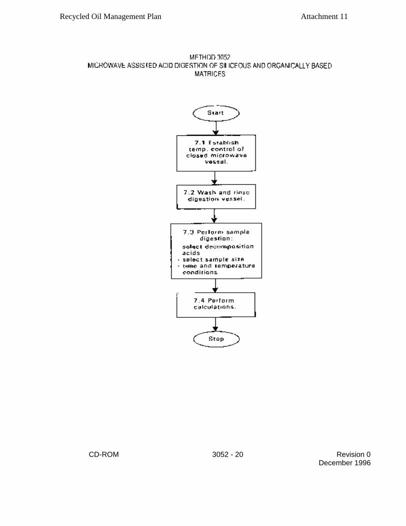
Recycled Oil Management Plan Attachment 11
CD-ROM 3052 - 20 Revision 0 December 1996
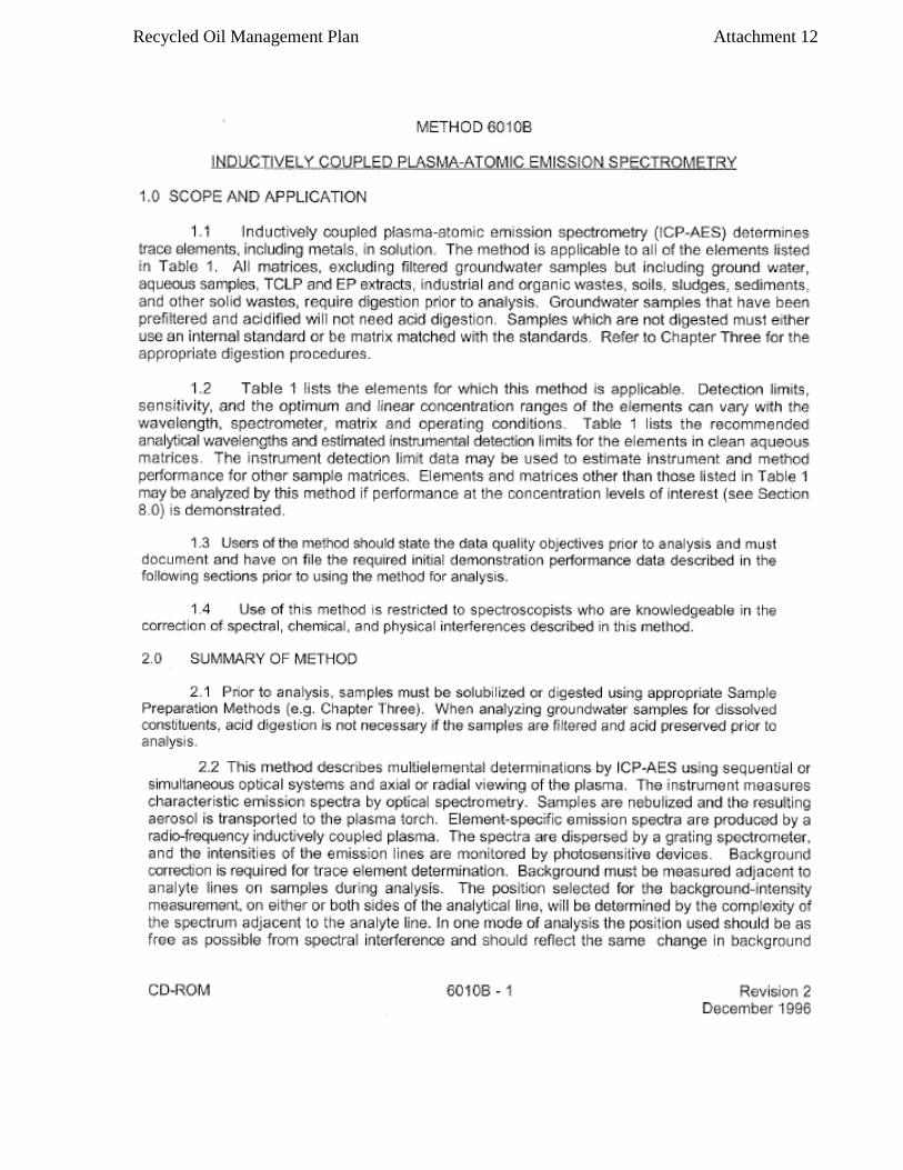
Recycled Oil Management Plan Attachment 12
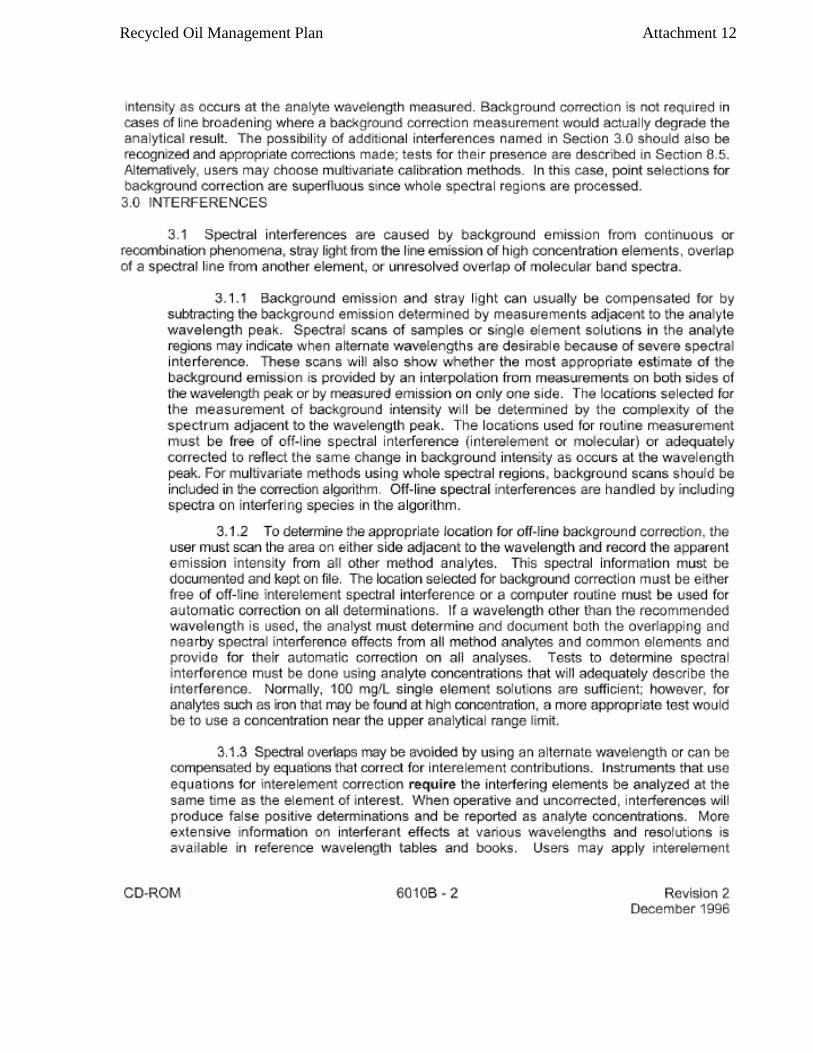
Recycled Oil Management Plan Attachment 12

Recycled Oil Management Plan Attachment 12

Recycled Oil Management Plan Attachment 12

Recycled Oil Management Plan Attachment 12

Recycled Oil Management Plan Attachment 12
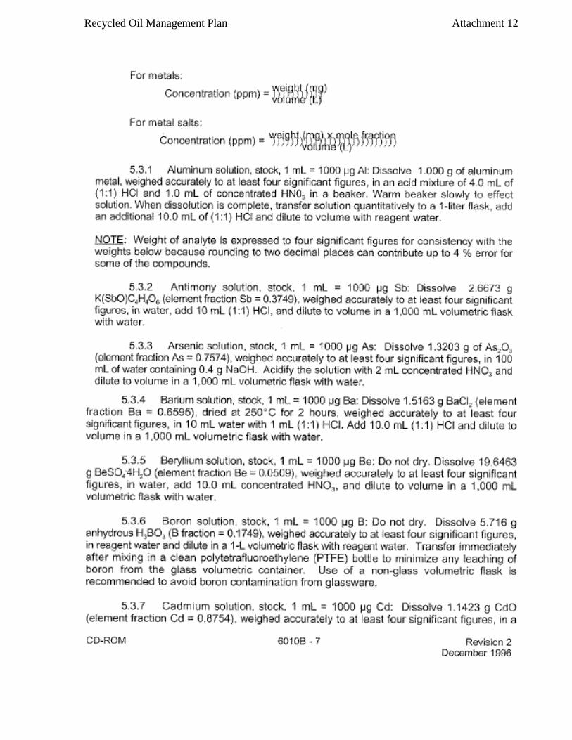
Recycled Oil Management Plan Attachment 12

Recycled Oil Management Plan Attachment 12

Recycled Oil Management Plan Attachment 12
Recycled Oil Management Plan Attachment 12

Recycled Oil Management Plan Attachment 12

Recycled Oil Management Plan Attachment 12

Recycled Oil Management Plan Attachment 12

Recycled Oil Management Plan Attachment 12

Recycled Oil Management Plan Attachment 12

Recycled Oil Management Plan Attachment 12
Recycled Oil Management Plan Attachment 12

Recycled Oil Management Plan Attachment 12

Recycled Oil Management Plan Attachment 12
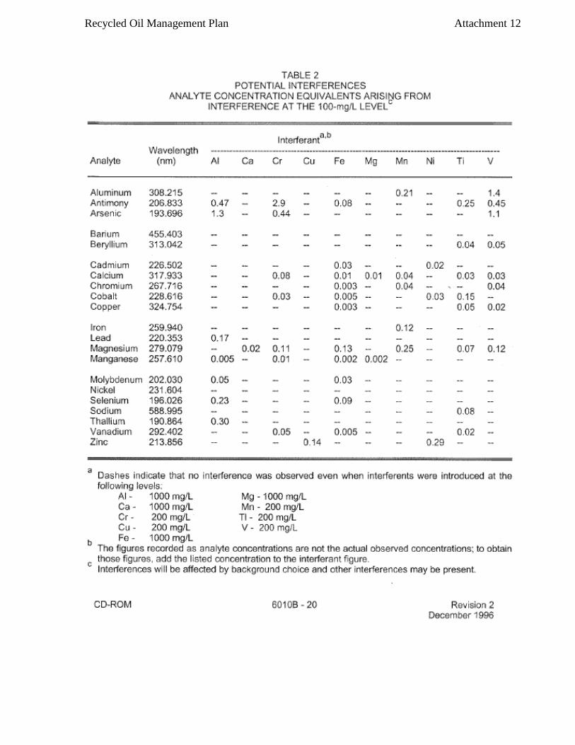
Recycled Oil Management Plan Attachment 12
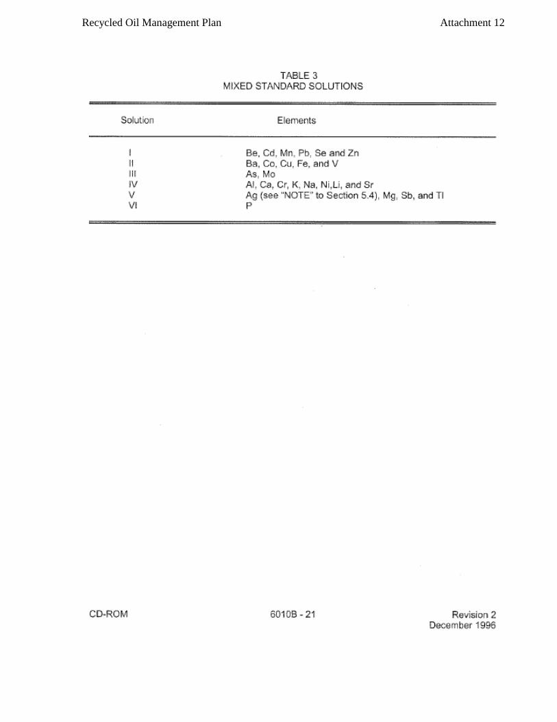
Recycled Oil Management Plan Attachment 12

Recycled Oil Management Plan Attachment 12

Recycled Oil Management Plan Attachment 12

Recycled Oil Management Plan Attachment 12

Recycled Oil Management Plan Attachment 12
Recycled Oil Management Plan Attachment 13
METHOD 6020
INDUCTIVELY COUPLED PLASMA - MASS SPECTROMETRY
1.0 SCOPE AND APPLICATION
1.1 Inductively coupled plasma-mass spectrometry (ICP-MS) is applicable to the
determination of sub-ug/L concentrations of a large number of elements in water
samples and in waste extracts or digests [1,2]. When dissolved constituents are
required, samples must be filtered and acid-preserved prior to analysis. No digestion
is required prior to analysis for dissolved elements in water samples. Acid digestion
prior to filtration and analysis is required for groundwater, aqueous samples,
industrial wastes, soils, sludges, sediments, and other solid wastes for which total
(acid-leachable) elements are required.
1.2 ICP-MS has been applied to the determination of over 60 elements in various
matrices. Analytes for which EPA has demonstrated the acceptability of Method 6020 in
a multi-laboratory study on solid wastes are listed in Table 1. Acceptability of the
method for an element was based upon the multi-laboratory performance compared with
that of either furnace atomic absorption spectroscopy or inductively coupled plasma-
atomic emission spectroscopy. It should be noted that the multi-laboratory study was
conducted in 1986. Multi-laboratory performance data for the listed elements (and
others) are provided in Section 9. Instrument detection limits, sensitivities, and
linear ranges will vary with the matrices, instrumentation, and operating conditions.
In relatively simple matrices, detection limits will generally be below 0.02 jug/L.
1.3 If Method 6020 is used to determine any analyte not listed in Table 1, it
is the responsibility of the analyst to demonstrate the accuracy and precision of the
Method in the waste to be analyzed. The analyst is always required to monitor
potential sources of interferences and take appropriate action to ensure data of known
quality (see Section 8.4).
1.4 Use of this method is restricted to spectroscopists who are knowledgeable
in the recognition and in the correction of spectral, chemical, and physical
interferences in ICP-MS.
1.5 An appropriate internal standard is required for each analyte determined by
ICP-MS. Recommended internal standards are 6Li, 45Sc, 89Y 103Rh, 115
In 159
Tb 165
Ho, and 209Bi .
The lithium internal standard should have an enriched abundance of 6Li, so that
interference from lithium native to the sample i s minimized. Other elements may need
to be used as internal standards when samples contain significant amounts of the
recommended internal standards.
2.0 SUMMARY OF METHOD
2.1 Prior to analysis, samples which require total ("acid-leachable") values
must be digested using appropriate sample preparation methods (such as Methods 3005 -
3051).
CD- ROM 6020-1 Revision 0
September 1994

Recycled Oil Management Plan Attachment 13
2.2 Method 6020 describes the multi-elemental determination of analytes
by ICP-MS. The method measures ions produced by a radio-frequency inductively
coupled plasma. Analyte species originating in a liquid are nebulized and the
resulting aerosol transported by argon gas into the plasma torch. The ions
produced are entrained in the plasma gas and introduced, by means of an interface,
into a mass spectrometer. The ions produced in the plasma are sorted according to
their mass-to-charge ratios and quantified with a channel electron multiplier.
Interferences must be assessed and valid corrections applied or the data flagged
to indicate problems. Interference correction must include compensation for
background ions contributed by the plasma gas, reagents, and constituents of the
sample matrix.
3.0 INTERFERENCES
3.1 Isobaric elemental interferences in ICP-MS are caused by isotopes of
different elements forming atomic ions with the same nominal mass-to-charge ratio
(m/z). A data system must be used to correct for these interferences. This
involves determining the signal for another isotope of the interfering element and
subtracting the appropriate signal from the analyte isotope signal. Since
commercial ICP-MS instruments nominally provide unit resolution at 10% of the peak
height, very high ion currents at adjacent masses can also contribute to ion
signals at the mass of interest. Although this type of interference is uncommon,
it is not easily corrected, and samples exhibiting a significant problem of this
type could require resolution improvement, matrix separation, or analysis using
another verified and documented isoptope, or use of another method.
3.2 Isobaric molecular and doubly-charged ion interferences in ICP-MS are
caused by ions consisting of more than one atom or charge, respectively. Most
isobaric interferences that could affect ICP-MS determinations have been
identified i n the literature [3,4] . Examples include ArCl+ ions on the 7S As
signal and Moo' ions on the cadmium isotopes. While the approach used to correct
for molecular isobaric interferences is demonstrated below using the natural
isotope abundances from the literature [5], the most precise coefficients for an
instrument can be determined from the ratio of the net isotope signals observed
for a standard solution at a concentration providing suitable (<1 percent)
counting statistics. Because the 35C1 natural abundance of 75.77 percent is 3.13
times the 37C1 abundance of 24.23 percent, the chloride correction for arsenic can
be calculated (approximately) as follows (where the 38Ar37C1+ contribution at m/z 75
is a negligible 0.06 percent of the 40Ar35CI+ signal):
corrected arsenic signal (using natural isotopes abundances for coefficient
approximations)=
(m/z 75 signal) - (3.13) (m/z 77 signal) + (2.73) (m/z 82 signal), (where the
final term adjusts for any selenium contribution at 77 m/z),
NOTE: Arsenic values can be biased high by this type of equation when the net
signal at m/z 82 is caused by ions other than 82 Se+, (e.g., 81BrH+ from bromine
wastes [6]).
CD-ROM 6020-2 Revision 0
September 1994

Recycled Oil Management Plan Attachment 13
Similarly,
corrected cadmium signal (using natural isotopes abundances for
coefficient approximations) =
(m/z 114 signal) - (0.027)(m/z 118 signal) - (1.63)(m/z 108 signal), (where last
2 terms adjust for any tin or Moo' contributions at m/z 114).
NOTE: Cadmium values will be biased low by this type of equation when 92Zr0'
ions contribute at m/z 108, but use of m/z 111 for Cd is even subject to direct
(94ZrOH+) and indirect ( 90ZrO+) additive interferences when Zr is present.
NOTE: As for the arsenic equation above, the coefficients in the Cd equation are
ONLY illustrative. The most appropriate coefficients for an instrument can be
determined from the ratio of the net isotope signals observed for a standard
solution at a concentration providing suitable (<1 percent) counting precision.
The accuracy of these types of equations is based upon the constancy of the OBSERVED
isotopic ratios for the interfering species. Corrections that presume a
constant fraction of a molecular ion relative to the "parent" ion have not been found
[7] to be reliable, e.g., oxide levels can vary. If a correction for an oxide ion is
based upon the ratio of parent-to-oxide ion intensities, the correction must be
adjusted for the degree of oxide formation by the use of an appropriate oxide internal
standard previously demonstrated to form a similar level of oxide as the interferant.
This type of correction has been reported [7] for oxide-ion corrections using ThO+/Th+
for the determination of rare earth elements. The use of aerosol desolvation and/or
mixed plasmas have been shown to greatly reduce molecular interferences [8]. These
techniques can be used provided that method detection limits, accuracy, and precision
requirements for analysis of the samples can be met.
3.3 Physical interferences are associated with the sample nebulization and
transport processes as well as with ion-transmission efficiencies. Nebulization and
transport processes can be affected if a matrix component causes a change in surface
tension or viscosity. Changes in matrix composition can cause significant signal
suppression or enhancement [9]. Dissolved solids can deposit on the nebul i zer tip of
a pneumatic nebul i zer and on the interface skimmers (reducing the orifice size and
the instrument performance). Total solid levels below 0.2% (2,000 mg/L) have been
currently recommended [10] to minimize solid deposition. An internal standard can be
used to correct for physical interferences, if it is carefully matched to the analyte
so that the two elements are similarly affected by matrix changes [11]. When the
intensity level of an internal standard is less than 30 percent or greater than 120
percent of the intensity of the first standard used during calibration, the sample
must be reanalyzed after a fivefold (1+4) or greater dilution has been performed.
3.4 Memory interferences can occur when there are large concentration
differences between samples or standards which are analyzed sequentially. Sample
CD-ROM 6020-3 Revision 0
September 1994
Recycled Oil Management Plan Attachment 13
deposition on the sampler and skimmer cones, spray chamber design, and the type of nebulizer affect the extent of the memory interferences which are observed. The rinse period between samples must be long enough to eliminate significant memory interference. 4.0 APPARATUS AND MATERIALS
4.1 Inductively coupled plasma-mass spectrometer:
4.1.1 A system capable of providing resolution, better than or equal to amu at 10% peak height is required. The system must have a mass range from at least 6 to 240 amu and a data system that allows corrections for isobaric interferences and the application of the internal standard technique. Use of a mass-flow controller for the nebulizer argon and a peristaltic pump for the sample solution are recommended.
4.1.2 Argon gas supply: high-purity grade (99.99%).
5.0 REAGENTS
5.1 Acids used in the preparation of standards and for sample processing must be of high purity. Redistilled acids are recommended because of the high sensitivity of ICP-MS. Nitric acid at less than 2 per cent (v/v) is required for ICP-MS to minimize damage to the interface and to minimize isobaric molecular-ion interferences with the analytes. Many more molecular-ion interferences are observed on the analytes when hydrochloric and sulfuric acids are used [3,4]. Concentrations of antimony and silver between 50-500 µg/L require 1% (v/v) HCl for stability; for concentrations above 500 µg/L Ag, additional HCl will be needed.
5.2 Reagent water: All references to water in the method refer to reagent water unless otherwise specified. Refer to Chapter One for a definition of reagent water.
5.3 Standard stock solutions may be purchased or prepared from ultra-high purity grade chemicals or metals (99.99 or greater purity). See Method 6010A, Section 5.3, for instructions on preparing standard solutions from solids.
5.3.1 Bismuth internal standard solution, stock, 1mL = 100ug Bi: Dissolve 0.1115 g Bi203 in a minimum amount of dilute HNO3. Add 10mL conc. HNO3 and dilute to 1,000mL with reagent water.
5.3.2 Holmium internal standard solution, stock, 1mL = 100 µg Ho:
Dissolve 0.1757 g H02(CO3)2.5H20 in 10mL reagent water and 10mL HNO3. After dissolution is complete, warm the solution to d egas. Add 10mL conc. HN03 and dilute to 1,000mL with reagent water.
CD-ROM 6020-4 Revision 0
September 1994

Recycled Oil Management Plan Attachment 13
5.3.3 Indium internal standard solution, stock, 1mL = 100 µg In: Dissolve 0.1000 g indium metal in 10mL conc. HNO3. Dilute to 1,000mL with reagent water.
5.3.4 Lithium internal standard solution, stock, 1mL = 100 jig
6Li: Dissolve 0.6312 g 95-atom-% 6Li, Li2CO3 in 10mL of reagent water and 10mL HNO3. After dissolution is complete, warm the solution to degas. Add 10mL conc. HNO3 and dilute to 1,000mL with reagent water.
5.3.5 Rhodium internal standard solution, stock, 1mL = 100 jig Rh:
Dissolve 0.3593 g ammonium hexachlororhodate (III) (NH4)3RhCl6 in 10mL reagent water. Add 100mL conc. HCl and dilute to 1,000mL with reagent water.
5.3.6 Scandium internal standard solution, stock, 1mL = 100 µg Sc:
Dissolve 0.15343 g Sc203 in 10mL (1+1) hot HNO3. Add 5mL conc. HNO3 and dilute to 1,000mL with reagent water.
5.3.7 Terbium internal standard solution, stock, 1mL = 100 jig Tb:
Dissolve 0.1828 g Tb2(C03)3. 5H2O i n 10mL (1+1) HNO3. After dissolution is complete, warm the solution to degas. Add 5mL conc. HNO3 and dilute to 1,000mL with reagent water.
5.3.8 Yttrium internal standard solution, stock, 1mL = 100 jig Y:
Dissolve 0.2316 g Y2(C03)3.3H2O in 10mL (1+1) HNO3. Add 5mL conc. HNO Sand dilute to 1,000mL with reagent water.
5.3.9 Titanium solution, stock, 1mL = 100 µg Ti: Dissolve 0.4133 g
(NH4)2TiF6 in reagent water. Add 2 drops conc. HF and dilute to 1,000mL with reagent water.
5.3.10 Molybdenum solution, stock, 1mL = 100ug Mo: Dissolve 0.2043
g (NH4)2Mo04 in reagent water. Dilute to 1,000mL with reagent water.
5.4 Mixed calibration standard solutions are prepared by diluting the stock-standard solutions to levels in the linear range for the instrument in a solvent consisting of 1 percent (v/v) HNO3 in reagent water. The calibration standard solutions must contain a suitable concentration of an appropriate internal standard for each analyte. Internal standards may be added on-line at the time of analysis using a second channel of the peristaltic pump and an appropriate mixing manifold.) Generally, an internal standard should be no more than 50amu removed from the analyte. Recommended internal standards include 6Li, 45Sc, 89Y, 103Rh, 15In, 159Th, 169 Ho, and 209 Bi. Prior to preparing the mixed standards, each stock solution must be analyzed separately to determine possible spectral interferences or the presence of impurities. Care must be taken when preparing the mixed standards that the elements are compatible and stable. Transfer the mixed standard solutions to freshly acid-cleaned FEP fluorocarbon bottles for storage. Fresh mixed standards must be prepared as needed with the realization that concentrations can change on aging. Calibration standards must be initially verified using a quality control standard (see Section 5.7) and monitored weekly for stability.
5.5 Blanks: Three types of blanks are required for the analysis. The calibration blank is used in establishing the calibration curve. The preparation blank is used to monitor for possible contamination resulting from
CD-ROM 6020-5 Revision 0
September 1994
Recycled Oil Management Plan Attachment 13
the sample preparation procedure. The rinse blank is used to flush the system between all samples and standards.
5.5.1 The calibration blank consists of the same concentration(s) of the same acids) used to prepare the final dilution of the calibrating solutions of the analytes [often 1 percent HNO3 (v/v) in reagent water] along with the selected concentrations of internal standards such that there is an appropriate internal standard element for each of the analytes. Use of HCl for antimony and silver is cited in Section 5.1
5.5.2 The preparation (or reagent) blank must be carried through
the complete preparation procedure and contain the same volumes of reagents as the sample solutions.
5.5.3 The rinse blank consists of 1 to 2 percent HNO3 (v/v) in
reagent water. Prepare a sufficient quantity to flush the system between standards and samples.
NOTE: The ICS solutions in Table 2 are intended to evaluate corrections for known interferences on only the analytes in Table 1. If Method 6020 is used to determine an element not listed in Table 1, it is the responsibility of the analyst to modify the ICS solutions, or prepare an alternative ICS solution, to allow adequate verification of correction of interferences on the unlisted element (see section 8.4).
5.6 The interference check solution (ICS) is prepared to contain known
concentrations of interfering elements that will demonstrate the magnitude of interferences and provide an adequate test of any corrections. Chloride in the ICS provides a means to evaluate software corrections for chloride-related interferences such as 35Cl160 + on 51 V+ and 40Ar35Cl+ on 75As+. Iron is used to demonstrate adequate resolution of the spectrometer for the determination of manganese. Molybdenum serves to indicate oxide effects on cadmium isotopes. The other components are present to evaluate the ability of the measurement system to correct for various molecular-ion isobaric interferences. The ICS is used to verify that the interference levels are corrected by the data system within quality control limits.
5.6.1 These solutions must be prepared from ultra-pure reagents. They can be obtained commercially or prepared by the following procedure.
5.6.1.1 Mixed ICS solution I may be prepared by adding
13.903g Al (N03)3.9H2O, 2.498g CaC03 (dried at 180 C for 1 h before weighing), 1.000g Fe, 1.658g MgO, 2.305g Na2CO3, and 1.767g K2C03 to 25mL of reagent water. Slowly add 40mL of (1+1) HNO3. After dissolution is complete, warm the solution to degas. Cool and dilute to 1,000mL with reagent water.
5.6.1.2 Mixed ICS solution II may be prepared by slowly
adding 7.444 g 85 % H3P04, 6.373 g 96% H2SO4, 40.024 g 37% HCl, and 10.664 g citric acid C60,H8 to 100mL of reagent water. Dilute to 1,000mL with reagent water.
5.6.1.3 Mixed ICS solution III may be prepared by adding
1.00mL each of 100-µg/mL arsenic, cadmium, chromium, cobalt, copper, manganese, nickel, silver, and zinc stock solutions to about
CD-ROM 6020-6 Revision 0
September 1994

Recycled Oil Management Plan Attachment 13
50mL reagent water. Add 2.0mL concentrated HNO3, and dilute to 100.0mL with reagent water.
5.6.1.4 Working ICS Solutions
5.6.1.4.1 ICS-A may be prepared by adding 10.0mL of
mixed ICS solution I (5.7.1.1), 2.0mL each of 100-ug/mL titanium stock solution (5.3.9) and molybdenum stock solution (5.3.10), and 5.0mL of mixed ICS solution II (5.7.1.2). Dilute to 100mL with reagent water. ICS solution A must be prepared fresh weekly.
5.6.1.4.2 ICS-AB may be prepared by adding 10.0mL of
mixed ICS solution I (5.7.1.1), 2.0mL each of 100-µg/mL titanium stock solution (5.3.9) and molybdenum stock solution (5.3.10), 5.0mL of mixed ICS solution II (5.7.1.2), and 2.0mL of Mixed ICS solution III (5.7.1.3). Dilute to 100mL with reagent water. Although the ICS solution AB must be prepared fresh weekly, the analyst should be aware that the solution may precipitate silver more quickly.
5.7 The quality control standard is the initial calibration verification
solution (ICV), which must be prepared in the same acid matrix as the calibration standards. This solution must be an independent standard near the midpoint of the linear range at a concentration other than that used for instrument calibration. An independent standard is defined as a standard composed of the analytes from a source different from those used in the standards for instrument calibration.
5.8 Mass spectrometer tuning solution. A solution containing elements representing all of the mass regions of interest (for example, 10 µg/L of Li, Co, In, and T1) must be prepared to verify that the resolution and mass calibration of the instrument are within the required specifications (see Section 7.5). This solution is also used to verify that the instrument has reached thermal stability (See Section 7.4). 6.0 SAMPLE COLLECTION, PRESERVATION, AND HANDLING
6.1 Sample collection procedures should address the considerations described in Chapter Nine of this Manual.
6.2 See the introductory material in Chapter Three, Inorganic Analytes, Sections 3.1.3 for information on sample handling and preservation. Only polyethylene or fluorocarbon (TFE or PFA) containers are recommended for use in Method 6020. 7.0 PROCEDURE
7.1 Solubilization and digestion procedures are presented in the Sample Preparation Methods (e.g., Methods 3005 - 3051).
7.2 Initiate appropriate operating configuration of the instruments computer according to the instrument manufacturer's instructions.
7.3 Set up the instrument with the proper operating parameters according to the instrument manufacturer's instructions.
CD-ROM 6020-7 Revision 0
September 1994

Recycled Oil Management Plan Attachment 13
7.4 Operating conditions: The analyst should follow the instructions provided by the instrument manufacturer. Allow at least 30 minutes for the instrument to equilibrate before analyzing any samples. This must be verified by analyzing a tuning solution (Section 5.8) at least four times with relative standard deviations of ≼ 5% for the analytes contained in the tuning solution.
NOTE: Precautions must be taken to protect the channel electron multiplier from high ion currents. The channel electron multiplier suffers from fatigue after being exposed to high ion currents. This fatigue can last from several seconds to hours depending on the extent of exposure. During this time period, response factors are constantly changing, which invalidates the calibration curve, causes instability, and invalidates sample analyses.
7.5 Conduct mass calibration and resolution checks in the mass regions of
interest. The mass calibration and resolution parameters are required criteria which must be met prior to any samples being analyzed. If the mass calibration differs more than 0.1amu from the true value, then the mass calibration must be adjusted to the correct value. The resolution must also be verified to be less than 0.9amu full width at 10 percent peak height.
7.6 Calibrate the instrument for the analytes of interest (recommended isotopes for the analytes in Table 1 are provided in Table 3), using the calibration blank and at least a single initial calibration standard according to the instrument manufacturer's procedure. Flush the system with the rinse blank (5.5.3) between each standard solution. Use the average of at leastthree integrations for both calibration and sample analyses.
7.7 All masses which could affect data quality should be monitored to determine potential effects from matrix components on the analyte peaks. The recommended isotopes to be monitored are liste in Table 3.
7.8 Immediately after the calibration has been established, the calibration must be verified and documented for every analyte by the analysis of the calibration verification solution (Section 5.7). When measurements exceed ± 10% of the accepted value, the analyses must be terminated, the problem corrected, the instrument recalibrated, and the new calibration verified. Any samples analyzed under an out-of-control calibration must be reanalyzed. During the course of an analytical run, the instrument may be "resloped" or recalibrated to correct for instrument drift. A recalibration must then be followed immediately by a new analysis of a CCV and CCB before any further samples may be analyzed.
7.9 Flush the system with the rinse blank solution (5.5.3) until the signal levels return to the method's levels of quantitation (usually about 30 seconds) before the analysis of each sample (see Section 7.7). Nebulize each sample until a steady-state signal is achieved (usually about 30 seconds) prior to collecting data. Analyze the calibration verification solution (Section 5.6) and the calibration blank (Section 5.5.1) at a frequency of at least once every 10 analytical samples. Flow-injection systems may be used as long as they can meet the performance criteria of this method.
7.10 Dilute and reanalyze samples that are more concentrated than the linear range for an analyte (or species needed for a correction) or measure an alternate less-abundant isotope. The linearity at the alternate mass must be confirmed by appropriate calibration (see Sec. 7.6 and 7.8).
CD-ROM 6020-8 Revision 0
September 1994

Recycled Oil Management Plan Attachment 13
7.11 Calculations: The quantitative values shall be reported in appropriate units, such as micrograms per liter(ug/L) for aqueous samples and milligrams per kilogram (mg/kg) for solid samples. If dilutions were performed, the appropriate corrections must be applied to the sample values.
7.11.1 If appropriate, or required, calculate results for solids on
a dry-weight basis as follows:
(1) A separate determination of percent solids must be performed.
(2) The concentrations determined in the digest are to be reported on the basis of the dry weight of the sample.
Concentration (dry weight)(mg/kg) = (CXV)/(WxS) Where,
C = Digest Concentration (mg/L) V = Final volume in liters after sample preparation
W = Weight in kg of wet sample
S = % Solids/100
Calculations should include appropriate interference corrections (see Section 3.2 for examples), internal-standard normalization, and the summation of
signals at 206, 207, and 208 m/z for lead (to compensate for any differences in the abundances of these isotopes between samples and standards). 8.0 QUALITY CONTROL
8.1 All quality control data should be maintained and be available for easy reference or inspection.
8.2 Instrument Detection Limits (IDLs) in ug/L can be estimated by calculating the average of the standard deviations of the three runs on three non-consecutive days from the analysis of a reagent blank solution with seven consecutive measurements per day. Each measurement must be performed as though it were a separate analytical sample (i.e., each measurement must be followed by a rinse and/or any other procedure normally performed between the analysis of separate samples). IDLs must be determined at least every three months and kept with the instrument log book. Refer to Chapter One for additional guidance.
8.3 The intensities of all internal standards must be monitored for every analysis. When the intensity of any internal standard fails to fall between 30 and 120 percent of the intensity of that internal standard in the initial calibration standard, the following procedure is followed. The sample must be diluted fivefold (1+4) and reanalyzed with the addition of appropriate amounts of internal standards. This procedure must be repeated until the internalstandard intensities fall within the prescribed window. The intensity levels of the internal standards for the calibration blank (Section 5.5.1) and instrument check standard (Section 5.6) must agree within ± 20 percent of the intensity level of the internal standard of the original calibration solution. If they do not agree, terminate the analysis, correct the problem, recalibrate, verify the new calibration, and reanalyze the affected samples.
CD-ROM 6020-9 Revision 0
September 1994

Recycled Oil Management Plan Attachment 13
8.4 To obtain analyte data of known quality, it is necessary to measure more than the analytes of interest in order to apply corrections or to determine whether interference corrections are necessary. If the concentrations of interference sources (such as C, Cl, Mo, Zr, W) are such that, at the correction factor, the analyte is less than the limit of quantification and the concentration of interferents are insignificant, then the data may go uncorrected. Note that monitoring the interference sources does not necessarily require monitoring the interferant itself, but that a molecular species may be monitored to indicate the presence of the interferent. When correcttion equations are used, all QC criteria must also be met. Extensive QC for interference corrections are required at all times. The monitored masses must include those elements whose hydrogen, oxygen, hydroxyl, chlorine, nitrogen, carbon and sulfur molecular ions could impact the analytes of interest. Unsuspected interferences may be detected by adding pure major matrix components to a sample to observe any impact on the analyte signals. When an interference source is present, the sample elements impacted must be flagged to indicate (a) the percentage interference correction applied to the data or (b) an uncorrected interference by virtue of the elemental equation used for quantitation. The isotope proportions for an element or molecular-ion cluster provide information useful for quality assurance.
NOTE: Only isobaric elemental, molecular, and doubly charged interference corrections which use the observed isotopic-response ratios or parent-tooxide ratios (provided an oxide internal standard is used as described in Section 3.2) for each instrument system are acceptable corrections for use in Method 6020.
8.5 Dilution Test: If the analyte concentration is within the linear
dynamic range of the instrument and sufficiently high (minimally, a factor of at least 100 times greater than the concentration in the reagent blank, refer to Section 5.5.2), an analysis of a fivefold (1+4) dilution must agree within ± 10% of the original determination. If not, an interference effect must be suspected. One dilution test must be included for each twenty samples (or less) of each matrix in a batch.
8.6 Post-Digestion Spike Addition: An analyte spike added to a portion of a prepared sample, or its dilution, should be recovered to within 75 to 125 percent of the known value or within the laboratory derived acceptance criteria. The spike addition should be based on the indigenous concentration of each element of interest in the sample. If the spike is not recovered within the specified limits, the sample must be diluted and reanalyzed to compensate for the matrix effect. Results must agree to within 10% of the original determination. The use of a standard-addition analysis procedure may also be used to compensate for this effect (Refer to Method 7000).
8.7 A Laboratory Control Sample (LCS) should be analyzed for each analyte using the same sample preparations, analytical methods and OA/QC procedures employed for the test samples. One LCS should be prepared and analyzed for each sample batch at a frequency of one LCS for each 20 samples or less.
8.8 Check the instrument calibration by analyzing appropriate quality control solutions as follows:
8.8.1 Check instrument calibration using a calibration blank (Section 5.5.1) and the initial calibration verification solution (Sections 5.7 and 7.9).
CD-ROM 6020-10 Revision 0
September 1994

Recycled Oil Management Plan Attachment 13
8.8.2 Verify calibration at a frequency of every 10 analytical samples with the instrument check standard (Section 5.6) and the calibration blank (Section 5.5.1). These solutions must also be analyzed for each analyte at the beginning of the analysis and after the last sample.
8.8.3 The results of the initial calibration verification solution
and the instrument check standard must agree within ± 10% of the expected value. If not, terminate the analysis, correct the problem, and recalibrate the instrument. Any sample analyzed under an out-of-control calibration must be reanalyzed .
8.8.4 The results of the calibration blank must be less than 3
times the current IDL for each element. If this is not the case, the reason for the out-of-control condition must be found and corrected, and affected samples must be reanalyzed. If the laboratory consistently has concentrations greater than 3 times the IDL, the IDL may be indicative of an estimated IDL and should be re-evaluated.
8.9 Verify the magnitude of elemental and molecular-ion isobaric
interferences and the adequacy of any corrections at the beginning of an analytical run or once every 12 hours, whichever is more frequent. Do this by analyzing the interference check solutions A and AB. The analyst should be aware that precipitation from solution AB may occur with some elements, specifically silver. Refer to Section 3.0 for a discussion on intereferences and potential solutions to those intereferences if additional guidance is needed.
8.10 Analyze one duplicate sample for every matrix in a batch at a frequency of one matrix duplicate for every 20 samples.
8.10.1 The relative percent difference (RPD) between duplicate determinations must be calculated as follows:
│ID, - Dz│
RPD = x 100 (D1 + D2)/2
where:
RPD = relative percent difference. D1 = first sample value. D2 = second sample value (duplicate)
A control limit of 20% RPD should not be exceeded for analyte values greater than 100 times the instrumental detection limit. If this limit is exceeded, the reason for the out-of-control situation must be found and corrected, and any samples analyzed during the out-of-control condition must be reanalyzed.
9.0 METHOD PERFORMANCE
9.1 In an EPA multi-laboratory study, 10 laboratories applied the ICP-MS technique to both aqueous and solid samples. TABLE 4 summarizes the method performance data for aqueous samples. Performance data for solid samples is provided in TABLE 5.
CD-ROM 6020-11 Revision 0
September 1994

Recycled Oil Management Plan Attachment 13
10.0 REFERENCES
1. Horlick, G., et al., Spectrochim. Acta 40B, 1555 (1985). 2. Gray, A.L., Spectrochim. Acta 40B, 1525 (1985); 41B, 151 (1986).
3. Tan, S.H., and Horlick, G., Appl. Spectrosc. 40, 445 (1986). 4.
Vaughan, M.A., and Horlick, G., Appl. Spectrosc. 40, 434 (1986).
5. Holden, N.E., "Table of the Isotopes," in Lide, D.R., Ed., CRC Handbook of Chemistry and Physics, 74th Ed., CRC Press, Boca Raton, FL, 1993. 6. Hinners, T.A., Heithmar, E., Rissmann, E., and Smith, D., Winter Conference on Plasma Spectrochemistry, Abstract THP18; p. 237, San Diego, CA (1994). 7. Lichte, F.[., et al., Anal. Chem. 59, 1150 (1987). 8. Evans E.H., and Ebdon, L., J. Anal. At. Spectrom. 4, 299 (1989).
9. Beauchemin, D., et al., Spectrochim. Acta 42B, 467 (1987). 10.
Houk, R.S., Anal. Chem. 58, 97A (1986).
11. Thompson, J.J., and Houk, R.S., Appl. Spectrosc. 41, 801 (1987).
CD-ROM 6020-12 Revision 0
September 1994

Recycled Oil Management Plan Attachment 13
TABLE 1. ELEMENTS APPROVED FOR ICP-MS DETERMINATION
Element CAS* #
Aluminum 7429-90-5 Antimony 7440-36-0 Arsenic 7440-38-2 Barium 7440-39-3 Beryllium 7440-41-7 Cadmium 7440-43-9 Chromium 7440-47-3 Cobalt 7440-48-4 Copper 7440-50-8 Lead 7439-92-1 Manganese 7439-96-5 Nickel 7440-02-0 Silver 7440-22-4 Thallium 7440-28-0 Zinc 7440-66-6
CD-ROM 6020-13 Revision 0
September 1994

Recycled Oil Management Plan Attachment 13
TABLE 2. RECOMMENDED INTERFERENCE CHECK SAMPLE COMPONENTS AND CONCENTRATIONS
Solution component
Solution A Concentration(mg/L)
Solution AB Concentration (mg/L)
Al 100.0 100.0 Ca 100.0 100.0 Fe 100.0 100.0 Mg 100.0 100.0 Na 100.0 100.0 P 100.0 100.0 K 100.0 100.0 S 100.0 100.0 C 200.0 200.0 Cl 1000.0 1000.0 Mo 2.0 2.0 Ti 2.0 2.0 As 0.0 0.0200 Cd 0.0 0.0200 Cr 0.0 0.0200 Co 0.0 0.0200 Cu 0.0 0.0200 Mn 0.0 0.0200 Ni 0.0 0.0200 Ag 0.0 0.0200 Zn 0.0 0.0200
CD-ROM 6020-14 Revision 0
September 1994

Recycled Oil Management Plan Attachment 13
TABLE 3. RECOMMENDED ISOTOPES FOR SELECTED ELEMENTS
Mass
Element of interest
27
Aluminum 121,
123 Antimony 75 Arsenic 138,
137, 136, 135, 134 Barium 9 Beryllium 209 Bismuth (IS) 114,
112, 111, 110, 113, 116,
106 Cadmium 42, 43, 44, 46, 48 Calcium (I) 35, 37, (77, 82)a Chlorine (I) 52, 53, 50, 54 Chromium 59 Cobalt 63, 65 Copper 165 Holmium (IS) 115,
113 Indium (IS) 56, 54, 57, 58 Iron (I) 139 Lanthanum (I) 208,
207, 206, 204 Lead 6b, 7 Lithium (IS) 24, 25, 26 Magnesium (I) 55 Manganese 98, 96, 92, 97,
94, (108)a Molybdenum (I)
58, 60, 62, 61, 64 Nickel 39 Potassium (I) 103 Rhodium (IS) 45 Scandium (IS) 107,
109 Silver 23 Sodium (I) 159 Terbium (IS) 205,
203 Thallium 120,
118 Tin (I) 89 Yttrium (IS) 64, 66,68, 67, 70 Zinc
NOTE: Method 6020 is recommended for only those analytes listed in Table 1. Other elements are included in this table because they are potential interferent (labeled 1) in the determination of recommended analytes, or they are commonly used internal standarda (labeled IS). Isotopes are listed in descending order of natural abundance. The most generally useful isotopes are underlined and in boldface, although certain matrices may require the use of alternative isotopes. a These masses are also useful for interference correction (Section 3.2). b Internal standard must be enriched in the6Li isotope. This minimizes interference from indigenous lithium.
CD-ROM 6020-15 Revision 0
September 1994
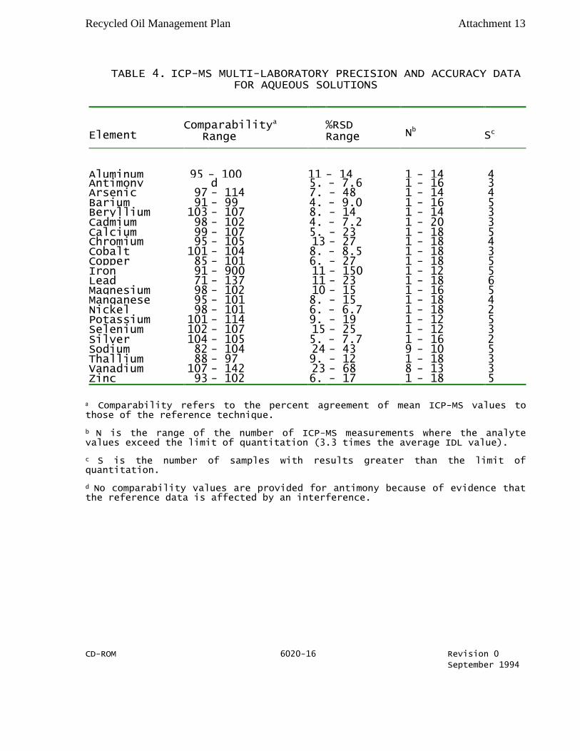
Recycled Oil Management Plan Attachment 13
TABLE 4. ICP-MS MULTI-LABORATORY PRECISION AND ACCURACY DATA FOR AQUEOUS SOLUTIONS
Element Comparabilitya
Range
%RSD Range Nb Sc
Aluminum 95 - 100 11 - 14 14 - 14 4
Antimony d 5.0
- 7.6 16 - 16 3
Arsenic 97 - 114 7.1
- 48 12 - 14 4
Barium 91 - 99 4.3
- 9.0 16 - 16 5
Beryllium 103 - 107 8.6
- 14 13 - 14 3
Cadmium 98 - 102 4.6
- 7.2 18 - 20 3
Calcium 99 - 107 5.7
- 23 17 - 18 5
Chromium 95 - 105 13 - 27 16 - 18 4
Cobalt 101 - 104 8.2
- 8.5 18 - 18 3
Copper 85 - 101 6.1
- 27 17 - 18 5
Iron 91 - 900 11 - 150 10 - 12 5
Lead 71 - 137 11 - 23 17 - 18 6
Magnesium 98 - 102 10 - 15 16 - 16 5
Manganese 95 - 101 8.8
- 15 18 - 18 4
Nickel 98 - 101 6.1
- 6.7 18 - 18 2
Potassium 101 - 114 9.9
- 19 11 - 12 5
Selenium 102 - 107 15 - 25 12 - 12 3
Silver 104 - 105 5.2
- 7.7 13 - 16 2
Sodium 82 - 104 24 - 43 9 - 10 5 Thallium 88 - 97 9.
7 - 12 1
8 - 18 3
Vanadium 107 - 142 23 - 68 8 - 13 3 Zinc 93 - 102 6.
8 - 17 1
6 - 18 5
a Comparability refers to the percent agreement of mean ICP-MS values to those of the reference technique.
b N is the range of the number of ICP-MS measurements where the analyte values exceed the limit of quantitation (3.3 times the average IDL value).
c S is the number of samples with results greater than the limit of quantitation.
d No comparability values are provided for antimony because of evidence that the reference data is affected by an interference.
CD-ROM 6020-16 Revision 0
September 1994
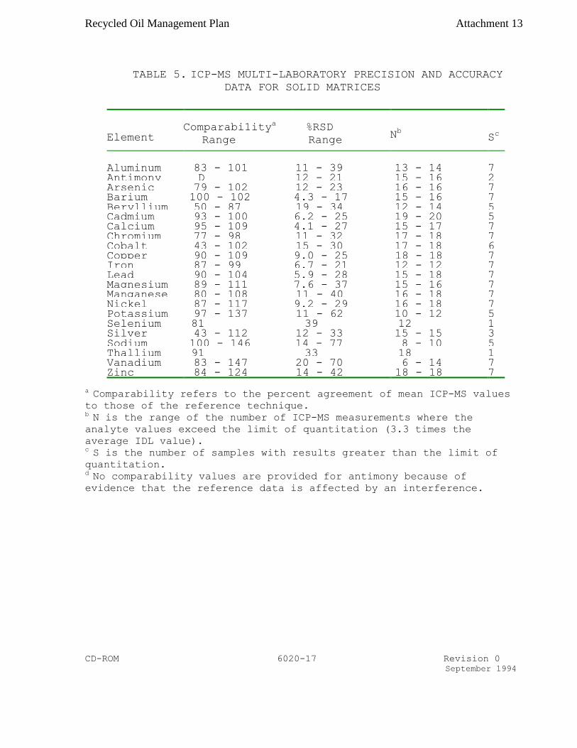
Recycled Oil Management Plan Attachment 13
TABLE 5. ICP-MS MULTI-LABORATORY PRECISION AND ACCURACY
DATA FOR SOLID MATRICES
Element Comparabi1ity
a
Range
%RSD
Range Nb S
c
Aluminum 83 - 101 11 - 39 13 - 14 7 Antimony D 12 - 21 15 - 16 2 Arsenic 79 - 102 12 - 23 16 - 16 7 Barium 100 - 102 4.3 - 17 15 - 16 7 Beryllium 50 - 87 19 - 34 12 - 14 5 Cadmium 93 - 100 6.2 - 25 19 - 20 5 Calcium 95 - 109 4.1 - 27 15 - 17 7 Chromium 77 - 98 11 - 32 17 - 18 7 Cobalt 43 - 102 15 - 30 17 - 18 6 Copper 90 - 109 9.0 - 25 18 - 18 7 Iron 87 - 99 6.7 - 21 12 - 12 7 Lead 90 - 104 5.9 - 28 15 - 18 7 Magnesium 89 - 111 7.6 - 37 15 - 16 7 Manganese 80 - 108 11 - 40 16 - 18 7 Nickel 87 - 117 9.2 - 29 16 - 18 7 Potassium 97 - 137 11 - 62 10 - 12 5 Selenium 81 39 12 1 Silver 43 - 112 12 - 33 15 - 15 3 Sodium 100 - 146 14 - 77 8 - 10 5 Thallium 91 33 18 1 Vanadium 83 - 147 20 - 70 6 - 14 7 Zinc 84 - 124 14 - 42 18 - 18 7
a Comparability refers to the percent agreement of mean ICP-MS values
to those of the reference technique. b N is the range of the number of ICP-MS measurements where the
analyte values exceed the limit of quantitation (3.3 times the
average IDL value). c S is the number of samples with results greater than the limit of
quantitation. d No comparability values are provided for antimony because of
evidence that the reference data is affected by an interference.
CD-ROM 6020-17 Revision 0
September 1994

Recycled Oil Management Plan Attachment 13
Start
7.1 Use
Method 3005
or Method
3015.
I s sample
oils, greases,
waxes?
7.1 Use
Method
3040.
7.1 Analyze by
Method 7000
or Method
6010.
Is H2O
acidified
pre-filtered?
7.2 Initiate
operating
configuration
of instrument
computer.
7.5 Perform
mass
calibration and
resolution
checks.
7.3 Set up and
stabilize
instrument.
7.4 Set
operating
conditions as
recommended.
7.7 Monitor all
masses which
could affect
data quality as
recommended.
7.6 Calibrate
the instrument
for the analytes
of interest.
7.11 Calculate
concentration.
7.8 Verify
calibration
with ICV.
Readjust
instrument per
manufacturer
recommendations
.
7.9 Analyze
check standard
and calibration
blank after each
10 samples.
Are results
outside +/-
10% range
of actual
value?
7.9 Flush
system and
analyze
sample.
Stop
Yes
No
Yes
Solid
GFAA
Aq
No
No
7.1 Use
Method
3020 or
Method
3015.
Is sample
analyzed by
FLAA/ICP
or GFAA?
Is sample
aqueous or
solid?
Is sample
water?
7.1 Use
Method 3050
or Method
3051.
Yes
No
Yes
FLAA/ICP
7.1 Use
Method 3010
or Method
3015.
7.10
Dilute
extract.
Does response
exceed calibr
curve range?
METHOD 6020
INDUCTIVELY COUPLED PLASMA
– MASS SPECTROMETRY

Recycled Oil Management Plan Attachment 14
Standard Operating Procedures for Recycled Oil Sample Collection
(#TPB 0017)
1.0 Purpose
The purpose of this SOP is to describe procedures to collect recycled oil samples from a variety
of receptacles or containers (e.g. tank, drum, barrel, boiler, and etc.)
Note: For your personal safety, make sure that the facility operator collects recycled oil samples
from the burner pipeline, large tanks and tank cars while the DAQ inspector observes the sample
collection process and ensures that the DAQ recommended procedures be followed. It is
considered that the inspectors are safe when collecting oil samples from drums, barrels, cans, etc.
Again it is advised that you be the judge of the situation and your safety, which should be of
prime importance.
2.0 References
The document “Recycled Oil Management Plan,” December 2002 contains more details on
recycled oil sample collection.
3.0 Equipment Description
Polyethylene Composite Liquid Waste Sampler (COLIWASA) recommended by the American
Society for Testing and Materials (ASTM) shall be used as the recycled oil sample collection
devise. The other equipment needs for this SOP are brown Nalgene bottles (capacity-1000ml),
disposable hand gloves, waste container, tissue wipes, self-adhesive labels and shipping cases.
Use only disposable COLIWASA samplers. Once used throw them away and never re-use.
Similarly, only new (unused) Nalgene bottles are to be used for recycled oil sample collection.
4.0 Procedures
4.1 Calibration and Certification
4.2 General Procedures
Activities related to recycled oil sample collection are summarized in Table 4-1.

Recycled Oil Management Plan Attachment 14
Table 4-1
Summary of Activities Related to Recycled Oil Collection
Sample Activity Program Plan
Equipment Polyethylene Composite Liquid Waste
Sampler (COLIWASA) and/or Drum Thief
Container New 1000 ml Brown Nalgene Bottle
Volume 950 ml
Labeling and Identification Use self-adhesive label and give sample
number in the field and complete (write) the
"Recycled Oil Sample Report."
Storage and Transportation Samples are stored and shipped in closed
containers. Transport samples to Toxics Lab
within 3 working days. At the Toxics Lab,
samples are aliquoted within 5 working days
and sent to analytical labs.
4.2.1 Arrival at the Facility: The facility operator should be informed that a
duplicate sample will be offered in a State-provided container and that
after completion of sampling, he/she will be asked to sign “Recycled Oil
Sample Report” acknowledging acceptance or rejection of a duplicate
sample. The purpose of collecting a duplicate sample is to allow the
facility the opportunity to analyze the same substance the State will be
analyzing. While at the facility, obtain a copy of the analytical report of
the recycled oil batch that will be sampled and attach it to the “Recycled
Oil Sample Report.” If this analytical report is not available, make
arrangements for the Toxics Protection Branch to receive a copy by
fax/mail.
4.2.2 Sampling Equipment: Use disposable COLIWASA for sample collection
from barrels, drums, tanks, tank cars and a Drum Thief for small cans (for
detail description of COLIWASA and Drum Thief, see Attachment 2 in
“Recycled Oil Management Plan,” December 2002).
4.2.3 Sample Container: Use a 1000 ml brown Nalgene bottle to collect
recycled oil samples. Use only new brown colored bottles to prevent
sample cross-contamination and to protect potential light-sensitive
materials in the recycled oil samples. Do not fill more than 95% of the
bottle capacity and leave room for thermal expansion of the sample during
storage and transport.
4.2.4 Sample volume: Collect approximately 950 ml (95% capacity of a 1000
ml brown Nalgene bottle). There is no need for precise sample volume
measurement. Analytical requirements are such that 950 ml sample
volume is considered to be adequate.
4.2.5 Sample Labeling and Identification: It is imperative that the sample
collected be immediately capped and labeled using “self-adhesive label”
and should be additionally secured using clear tape. The person collecting
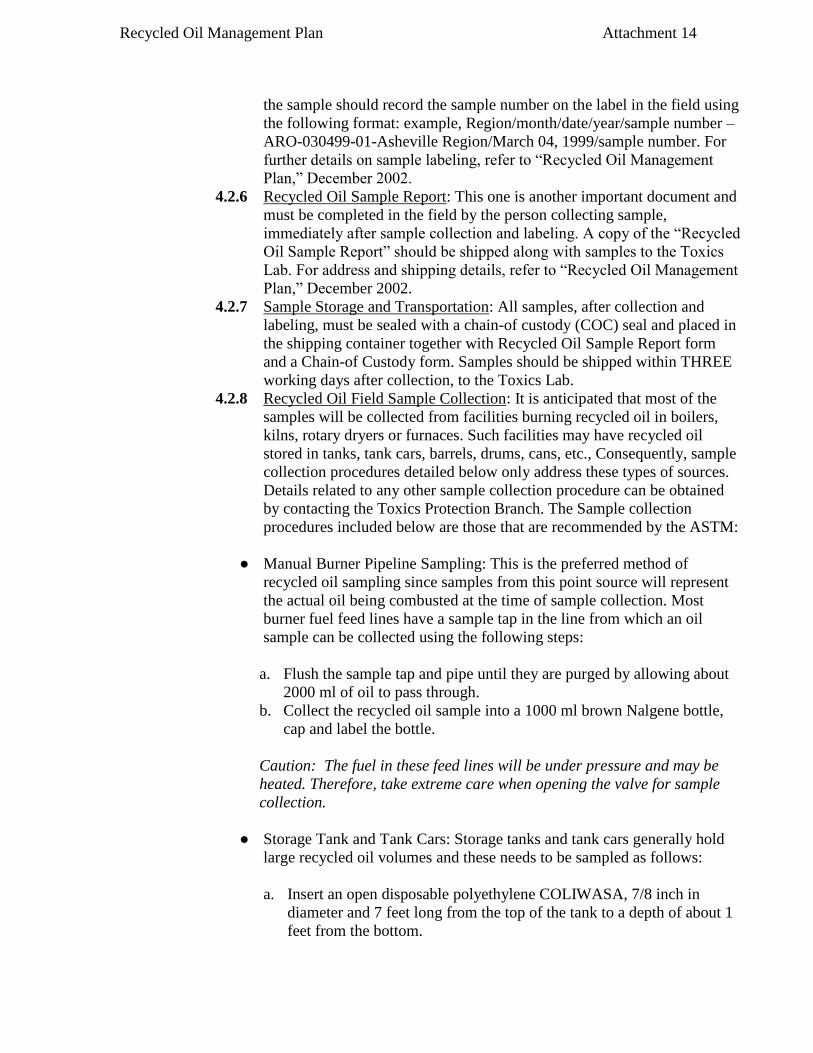
Recycled Oil Management Plan Attachment 14
the sample should record the sample number on the label in the field using
the following format: example, Region/month/date/year/sample number –
ARO-030499-01-Asheville Region/March 04, 1999/sample number. For
further details on sample labeling, refer to “Recycled Oil Management
Plan,” December 2002.
4.2.6 Recycled Oil Sample Report: This one is another important document and
must be completed in the field by the person collecting sample,
immediately after sample collection and labeling. A copy of the “Recycled
Oil Sample Report” should be shipped along with samples to the Toxics
Lab. For address and shipping details, refer to “Recycled Oil Management
Plan,” December 2002.
4.2.7 Sample Storage and Transportation: All samples, after collection and
labeling, must be sealed with a chain-of custody (COC) seal and placed in
the shipping container together with Recycled Oil Sample Report form
and a Chain-of Custody form. Samples should be shipped within THREE
working days after collection, to the Toxics Lab.
4.2.8 Recycled Oil Field Sample Collection: It is anticipated that most of the
samples will be collected from facilities burning recycled oil in boilers,
kilns, rotary dryers or furnaces. Such facilities may have recycled oil
stored in tanks, tank cars, barrels, drums, cans, etc., Consequently, sample
collection procedures detailed below only address these types of sources.
Details related to any other sample collection procedure can be obtained
by contacting the Toxics Protection Branch. The Sample collection
procedures included below are those that are recommended by the ASTM:
● Manual Burner Pipeline Sampling: This is the preferred method of
recycled oil sampling since samples from this point source will represent
the actual oil being combusted at the time of sample collection. Most
burner fuel feed lines have a sample tap in the line from which an oil
sample can be collected using the following steps:
a. Flush the sample tap and pipe until they are purged by allowing about
2000 ml of oil to pass through.
b. Collect the recycled oil sample into a 1000 ml brown Nalgene bottle,
cap and label the bottle.
Caution: The fuel in these feed lines will be under pressure and may be
heated. Therefore, take extreme care when opening the valve for sample
collection.
● Storage Tank and Tank Cars: Storage tanks and tank cars generally hold
large recycled oil volumes and these needs to be sampled as follows:
a. Insert an open disposable polyethylene COLIWASA, 7/8 inch in
diameter and 7 feet long from the top of the tank to a depth of about 1
feet from the bottom.

Recycled Oil Management Plan Attachment 14
b. Pull up the plunger on COLIWASA and seal the end while removing
the sample.
c. Release the sample into Nalgene bottle.
d. Repeat these steps until the desired sample volume of 950 ml is
obtained.
● Drums, Barrels and Cans: Barrels, drums and cans containing recycled oil
can be sampled using disposable COWLIWASA or Drum Thief. If there is
more than one Barrel/drum at the facility, collect an equal volume portion
from each to make up a composite sample volume of 950 ml. In this case,
describe details of sampling and or sample locations in the “ Recycled Oil
Sample Report”.
For drums and barrels, a 7/8 inch diameter and 42 inch long COLIWASA
holding 250 ml sample volume is also ideal. Repeat all sample collection
steps described in 4.8.2 to collect a 950 ml recycled oil sample.
Additionally, a Drum Thief (12-mm in diameter and 42 inches long) may
be used to collect recycled oil samples:
a. Insert the Drum Thief into the container, while covering the open end
with your thumb.
b. Remove the sampling device and transfer the sample into a 1000 ml
Nalgene bottle.
c. Repeat the above steps until the desired sample volume is obtained.
5.0 Maintenance
Not applicable
6.0 Safety
It is the policy of the Division of Air Quality (DAQ) that your personal safety is of prime
importance during recycled oil sample collection. Ultimately, it is you that must determine in the
field, whether or not sampling can be performed in a controlled and safe environment. For most
sampling visits, Level D protective clothing is appropriate which should include use of steel-toed
safety shoes or boots, hard hat, protective hand gloves, and safety glasses. For your personal
safety, make sure that the facility operator collects recycled oil samples from the burner pipeline,
large tanks and tank cars while the DAQ inspector observes the sample collection process and
ensures that the DAQ recommended procedures be followed. It is considered that the inspectors
are safe when collecting oil samples from drums, barrels, cans, etc. Again it is advised that you
be the judge of the situation and your safety, which should be of prime importance. Always take
a waste container for disposal of wipes and gloves and dispose these items in appropriate waste
containers, preferably on the facility property.
7.0 General Notes and Comments Not applicable

Recycled Oil Management Plan Attachment 14
8.0 Storage
There are no specific storage requirements for recycled oil samples. Samples are reported to be
stable at room temperature for at least 6 (six) months.
9.0 Attachments
For additional details refer to “Recycled Oil Management Plan,” December 2002.

Recycled Oil Management Plan Attachment 15
RECYCLED OIL ALIQUOTING
1.0 Purpose
The purpose of this document is to define a standard operating procedure (SOP) for the recycled oil
sample aliquoting.
2.0 References
North Carolina Division of Air Quality “Recycled Oil Management Plan”
3.0 Equipment Description
Amber Nalgene Sample bottle 500 ml, funnel, safety glasses, Gloves, fume hood.
4.0 Procedures
4.1 The samples received in the laboratory must be in a 1000 ml amber Nalgene sample
bottles.
4.2 General Operations
Under a hood the 1000 ml sample should be agitated properly to maintain a homogeneous
sample. The sample is poured using a funnel into two 500 ml bottles.
5 Maintenance
The funnel should be washed in hot water and detergent after every use. Use new Nalgene sample
bottles for every recycled oil sample.
6 Safety
All sample aliquoting should be done under a hood. Gloves and aprons and safety glasses will be
used at all times.

Recycled Oil Management Plan Attachment 15