NORTH ATLANTIC MNPS AIRSPACE OPERATIONS MANUALleonardo-in-flight.nl/PDF/North Atlantic MNPS Airspace...
102
NAT MNPS NORTH ATLANTIC MNPS AIRSPACE OPERATIONS MANUAL - Edition 2005 - Published on behalf of the North Atlantic Systems Planning Group (NAT SPG) by the European and North Atlantic Office of ICAO
Transcript of NORTH ATLANTIC MNPS AIRSPACE OPERATIONS MANUALleonardo-in-flight.nl/PDF/North Atlantic MNPS Airspace...
NAT MNPS
NORTH ATLANTIC MNPS AIRSPACE
OPERATIONS MANUAL
- Edition 2005 -
Published on behalf of the North Atlantic Systems Planning Group (NAT SPG) by the European and North Atlantic Office of ICAO

NORTH ATLANTIC MNPSA OPERATIONS MANUAL
NAT MNPS i Edition 2005
EXCLUSION OF LIABILITY
A printed or electronic copy of this Manual, plus any associated documentation, is provided to the recipient as is and without any warranties as to its description, condition, quality, fitness for purpose or functionality and for use by the recipient solely for guidance only. Any implied conditions terms or warranties as to the description, condition, quality, fitness for purpose or functionality of the software and associated documentation are hereby excluded.
The information published by ICAO on this document is made available without warranty of any kind; the Organization accepts no responsibility or liability whether direct or indirect, as to the currency, accuracy or quality of the information, nor for any consequence of its use.
The designations and the presentation of material in this publication do not imply the expression of any opinion whatsoever on the part of ICAO concerning the legal status of any country, territory, city or area of its authorities, or concerning the delimitation of its frontiers or boundaries.
First published December 1979 Second edition September 1980 Third edition December 1981 Fourth edition October 1984 Fifth edition June 1988 Sixth edition December 1993 Seventh edition December 1997 Eighth edition April 1999 Ninth edition September 2000 Edition 2005 September 2005 There is no objection to the reproduction of extracts of information contained in this Document if the source is acknowledged.
NORTH ATLANTIC MNPSA OPERATIONS MANUAL
NAT MNPS ii Edition 2005
FOREWORD
This Document is for guidance only. Regulatory material relating to North Atlantic aircraft operations is contained in relevant ICAO Annexes, PANS/ATM (Doc.4444), Regional Supplementary Procedures (Doc.7030), State AIPs and current NOTAMs, which should be read in conjunction with the material contained in this Document.
The NAT MNPS – Edition 2005 is an updated version of Guidance Material first published in 1979 and is primarily for the information of pilots and dispatchers planning and conducting operations in North Atlantic (NAT) Minimum Navigation Performance Specification (MNPS) Airspace.
The Manual has been produced with the approval and on behalf of the North Atlantic Systems Planning Group (NAT SPG); a North Atlantic regional planning body established under the auspices of the International Civil Aviation Organisation (ICAO). This Group is responsible for developing the required operational procedures; specifying the necessary services and facilities and; defining the aircraft and operator approval standards employed in the NAT Region.
Edited by European and North Atlantic Office of ICAO 3 bis, Villa Emille Bergerat 92522 Neuilly-sur-Seine Cedex – France Tel: +33 1 4641 8585 Fax : +33 1 4641 8500 Email: [email protected] http://www.paris.icao.int/
This Document will be made available to users from a number of web sites including the NAT Programme Co-ordination Office (PCO) web site: http://www.nat-pco.org/ . The PCO web site will also include, any errata (changes) or addenda (additions) to the current edition of the Manual. the Manual will be reissued on a yearly basis in September. Details of additional Internet access will be promulgated through the Aeronautical Information Service (AIS) of NAT ATS Provider States.
Further material, for the information of States of Registry and Aircraft Operating Agencies, dealing primarily with planning and management aspects of NAT MNPS operations, is contained in ICAO ‘Consolidated Guidance and Information Material concerning Air Navigation in the North Atlantic Region’ (NAT Doc 001), published by the European and North Atlantic Office of ICAO and available at http://www.nat-pco.org/.
To assist with the editing of this Manual and to ensure the currency and accuracy of future editions it would be appreciated if readers would submit their comments/suggestions for possible amendments/additions, to the ICAO EUR/NAT Office at the above Email address.
The NATSPG has also commissioned the UK National Air Traffic Services to produce an interactive DVD ROM, “On the Right Track”, which contains general information on Air Traffic Control in the North Atlantic Region and which highlights many of the common operational errors and discusses their causes. This DVD ROM, like this Manual, is aimed at pilots, dispatchers and others concerned in operations on the North Atlantic. It is available at no charge to bona fide operators on application to: [email protected].
NORTH ATLANTIC MNPSA OPERATIONS MANUAL
NAT MNPS iii Edition 2005
As part of the continuing development within the operating environment of NAT MNPS Airspace, various trials take place in the NAT from time to time. Some of these trials require the assistance of operators and pilots. For a listing of current trials (if any) and participation details etc., reference should be made to the AIS documentation of NAT ATS Provider States. Details may also be found on the above-mentioned PCO web site.
MINIMUM NAVIGATION PERFORMANCE SPECIFICATION AIRSPACE
The vertical dimension of MNPS Airspace is between FL285 and FL420 (i.e. in terms of normally used cruising levels, from FL290 to FL410 inclusive).
The lateral dimensions include the following Control Areas (CTAs):
REYKJAVIK SHANWICK, GANDER and SANTA MARIA OCEANIC NEW YORK OCEANIC North of 27°N but excluding the area west of 60°W and
south of 38°30'N
Some idea of these dimensions can be obtained from the map on the cover and the maps in Chapters 2 and 3. However, for specific dimensions, reference should be made to ICAO Regional Supplementary Procedures (Doc.7030) - NAT/RAC (available at http://www.nat-pco.org/).
Pilots MUST NOT fly across the North Atlantic within MNPS Airspace, nor at flight levels 290 to 410 inclusive anywhere within the NAT Region, unless they are in possession of the appropriate Approval(s) issued by the State of Registry or the State of the Operator.
The North Atlantic is the busiest oceanic airspace in the world. In 2004 more than 370,000 flights crossed the North Atlantic and annual traffic growth rates are now returning to the typical figures of between 5% and 10%. For the most part in the North Atlantic, Direct Controller Pilot Communications (DCPC) and Radar Surveillance are unavailable. Aircraft separation assurance and hence safety are nevertheless ensured by demanding the highest standards of horizontal and vertical navigation performance/accuracy and of operating discipline. Within NAT MNPS Airspace a formal Approval Process by the State of Registry of the aircraft or the State of the Operator ensures that aircraft meet defined MNPS Standards and that appropriate crew procedures and training have been adopted.
NORTH ATLANTIC MNPSA OPERATIONS MANUAL
NAT MNPS iv Edition 2005
AMENDMENTS TO THE NAT MNPS MANUAL
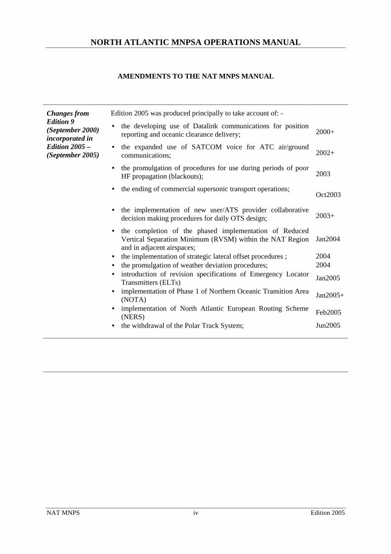
Edition 2005 was produced principally to take account of: -
• the developing use of Datalink communications for position reporting and oceanic clearance delivery; 2000+
• the expanded use of SATCOM voice for ATC air/ground communications; 2002+
• the promulgation of procedures for use during periods of poor HF propagation (blackouts); 2003
• the ending of commercial supersonic transport operations; Oct2003
• the implementation of new user/ATS provider collaborative decision making procedures for daily OTS design; 2003+
• the completion of the phased implementation of Reduced Vertical Separation Minimum (RVSM) within the NAT Region and in adjacent airspaces;
Jan2004
• the implementation of strategic lateral offset procedures ; 2004 • the promulgation of weather deviation procedures; 2004 • introduction of revision specifications of Emergency Locator
Transmitters (ELTs) Jan2005
• implementation of Phase 1 of Northern Oceanic Transition Area (NOTA) Jan2005+
• implementation of North Atlantic European Routing Scheme (NERS) Feb2005
Changes from Edition 9 (September 2000) incorporated in Edition 2005 –(September 2005)
• the withdrawal of the Polar Track System; Jun2005
NORTH ATLANTIC MNPSA OPERATIONS MANUAL
NAT MNPS v Edition 2005
GLOSSARY OF TERMS
ACARS Aircraft Communications Addressing and Reporting System ACAS Airborne Collision Avoidance System ACC Area Control Centre ADC Air Data Computer ADF Automatic Direction Finding ADS Automatic Dependant Surveillance AFTN Aeronautical Fixed Telecommunication Network AGHME Aircraft Geometric Height Measuring Element AIC Aeronautical Information Circular AIP Aeronautical Information Publication AIS Aeronautical Information Service ARINC ARINC - formerly Aeronautical Radio Incorporated ASR Aviation Safety Report ATA Actual Time of Arrival ATC Air Traffic Control ATM Air Traffic Management ATS Air Traffic Services AWPR Automatic Waypoint Position Reporting BOTA Brest Oceanic Transition Area BRNAV Basic Area Navigation CAR Caribbean CDL Configuration Deviation List CDR ConDitional Route CDU Control Display Unit CMA Central Monitoring Agency CPDLC Controller Pilot Data Link Communications CTA Control Area DCPC Direct Controller/Pilot Communications DME Distance Measuring Equipment DR Dead Reckoning DVD ROM Digital Video Disk Read-Only Memory ELT Emergency Locator Transmitter ETA Estimated Time of Arrival ETOPS Extended Range Twin-engine Aircraft Operations EUR Europe FAA Federal Aviation Administration FANS 1/A Future Air Navigation System 1 or A. (Respectively, Boeing and Airbus
Proprietary Air-Ground ATC Data Link Communications Systems) FDE Fault Detection and Exclusion
NORTH ATLANTIC MNPSA OPERATIONS MANUAL
NAT MNPS vi Edition 2005
FIR Flight Information Region FL Flight Level FLAS Flight Level Allocation Scheme FMC Flight Management Computer FMS Flight Management System GLONASS Global Orbiting Navigation Satellite System GMU GPS (Height) Monitoring Unit GNE Gross Navigation Error GNSS Global Navigation Satellite System GP General Purpose GPS Global Positioning System HF High Frequency HMU Height Monitoring Unit HSI Horizontal Situation Indicator IATA International Air Transport Association ICAO International Civil Aviation Organisation IFR Instrument Flight Rules INS Inertial Navigation System IRS Inertial Reference System JAA Joint Aviation Authorities kHz Kilohertz LAT Latitude LONG Longitude LRNS Long Range Navigation System MASPS Minimum Aircraft System Performance Specification MEL Minimum Equipment List MET Meteorological MHz Megahertz MMEL Master Minimum Equipment List MNPS Minimum Navigation Performance Specification MTT Minimum Time Track NAM North America NAR North American Route NAT North Atlantic NAT SPG North Atlantic Systems Planning Group NDB Non Directional Beacon NERS North Atlantic European Routing Scheme nm Nautical Mile NOAA National Oceanic and Atmospheric Administration NOTA Northern Oceanic Transition Area
NORTH ATLANTIC MNPSA OPERATIONS MANUAL
NAT MNPS vii Edition 2005
NOTAM Notice to Airmen OAC Oceanic Area Control Centre OCA Oceanic Control Area Oceanic Entry Point That point on the FIR boundary where the aircraft enters the first oceanic
control area Oceanic Exit Point That point on the FIR boundary where the aircraft leaves the last oceanic
control area OTS Organized Track System PRM Preferred Route Message RA Resolution Advisory (per ACAS) RAIM Receiver-Autonomous Integrity Monitoring RMI Remote Magnetic Indicator RNP Required Navigation Performance R/T Radio Telephony RVSM Reduced Vertical Separation Minimum SAM South America SELCAL Selective Calling SID Standard Instrument Departure SLOP Strategic Lateral Offset Procedure SOTA Shannon Oceanic Transition Area SSB Single Sideband SSR Secondary Surveillance Radar TA Traffic Advisory (per ACAS) TAS True Airspeed TCAS Traffic (Alert and) Collision Avoidance System TLS Target Level of Safety TMI Track Message Identification UTC Co-ordinated Universal Time VHF Very High Frequency VOR VHF Omni-directional Range WAH When Able Higher WATRS West Atlantic Route System WPR Waypoint Position Report
NORTH ATLANTIC MNPSA OPERATIONS MANUAL
NAT MNPS viii Edition 2005
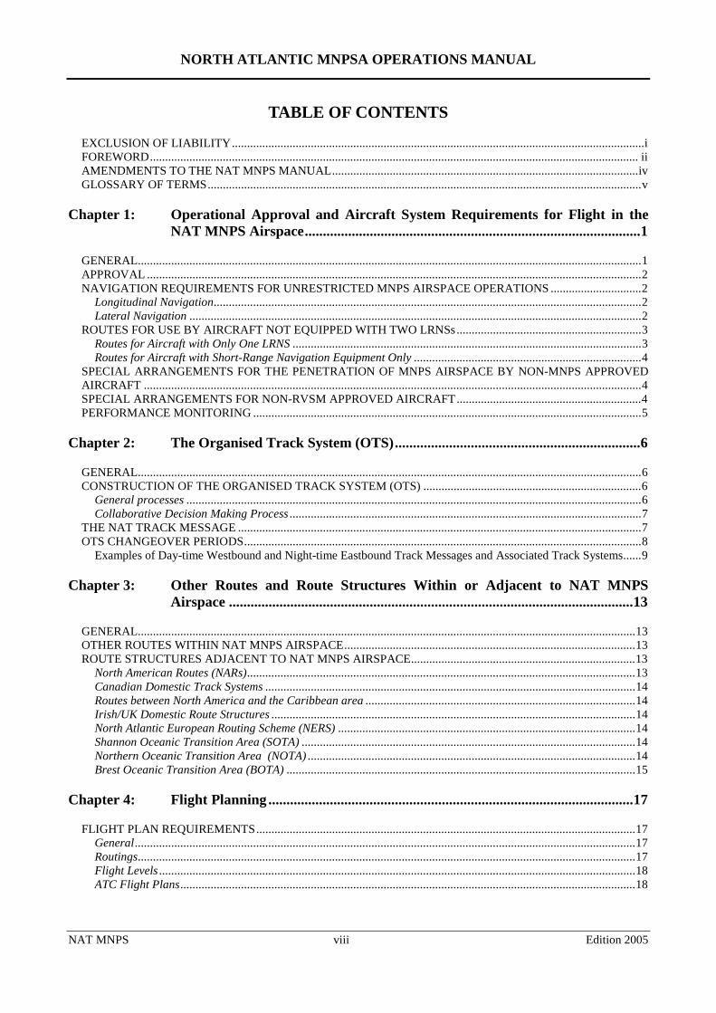
TABLE OF CONTENTS
EXCLUSION OF LIABILITY........................................................................................................................................i FOREWORD................................................................................................................................................................. ii AMENDMENTS TO THE NAT MNPS MANUAL.....................................................................................................iv GLOSSARY OF TERMS...............................................................................................................................................v
Chapter 1: Operational Approval and Aircraft System Requirements for Flight in the NAT MNPS Airspace.............................................................................................1
GENERAL......................................................................................................................................................................1 APPROVAL ...................................................................................................................................................................2 NAVIGATION REQUIREMENTS FOR UNRESTRICTED MNPS AIRSPACE OPERATIONS ..............................2
Longitudinal Navigation.............................................................................................................................................2 Lateral Navigation .....................................................................................................................................................2
ROUTES FOR USE BY AIRCRAFT NOT EQUIPPED WITH TWO LRNSs.............................................................3 Routes for Aircraft with Only One LRNS ...................................................................................................................3 Routes for Aircraft with Short-Range Navigation Equipment Only ...........................................................................4
SPECIAL ARRANGEMENTS FOR THE PENETRATION OF MNPS AIRSPACE BY NON-MNPS APPROVED AIRCRAFT ....................................................................................................................................................................4 SPECIAL ARRANGEMENTS FOR NON-RVSM APPROVED AIRCRAFT.............................................................4 PERFORMANCE MONITORING ................................................................................................................................5
Chapter 2: The Organised Track System (OTS)....................................................................6
GENERAL......................................................................................................................................................................6 CONSTRUCTION OF THE ORGANISED TRACK SYSTEM (OTS) ........................................................................6
General processes ......................................................................................................................................................6 Collaborative Decision Making Process ....................................................................................................................7
THE NAT TRACK MESSAGE .....................................................................................................................................7 OTS CHANGEOVER PERIODS...................................................................................................................................8
Examples of Day-time Westbound and Night-time Eastbound Track Messages and Associated Track Systems......9
Chapter 3: Other Routes and Route Structures Within or Adjacent to NAT MNPS Airspace ................................................................................................................13
GENERAL....................................................................................................................................................................13 OTHER ROUTES WITHIN NAT MNPS AIRSPACE................................................................................................13 ROUTE STRUCTURES ADJACENT TO NAT MNPS AIRSPACE..........................................................................13
North American Routes (NARs)................................................................................................................................13 Canadian Domestic Track Systems ..........................................................................................................................14 Routes between North America and the Caribbean area .........................................................................................14 Irish/UK Domestic Route Structures ........................................................................................................................14 North Atlantic European Routing Scheme (NERS) ..................................................................................................14 Shannon Oceanic Transition Area (SOTA) ..............................................................................................................14 Northern Oceanic Transition Area (NOTA) ............................................................................................................14 Brest Oceanic Transition Area (BOTA) ...................................................................................................................15
Chapter 4: Flight Planning .....................................................................................................17
FLIGHT PLAN REQUIREMENTS.............................................................................................................................17 General.....................................................................................................................................................................17 Routings....................................................................................................................................................................17 Flight Levels .............................................................................................................................................................18 ATC Flight Plans......................................................................................................................................................18
NORTH ATLANTIC MNPSA OPERATIONS MANUAL
NAT MNPS ix Edition 2005
FLIGHT PLANNING REQUIREMENTS ON SPECIFIC ROUTES..........................................................................19 Flights Planning on the Organised Track System ....................................................................................................19 Flights Planning on Random Route Segments in a Generally Eastbound or Westbound Direction at/or South of 70°N..........................................................................................................................................................................19 Flights Planning on a Generally Eastbound or Westbound Direction on Random Route Segments North of 70°N 20 Flights Planning on Random Routes in a Generally Northbound or Southbound Direction ...................................20 Flights Planning to Operate Without HF Communications .....................................................................................20
Chapter 5: Oceanic ATC Clearances.....................................................................................21
GENERAL....................................................................................................................................................................21 CONTENTS OF CLEARANCES ................................................................................................................................22 OCEANIC CLEARANCES FOR WESTBOUND FLIGHTS ROUTING VIA 61°N 010°W.....................................23 OCEANIC CLEARANCES FOR FLIGHTS INTENDING TO OPERATE WITHIN THE NAT REGION AND SUBSEQUENTLY ENTER THE EUR OR NAM REGIONS.....................................................................................23 OCEANIC CLEARANCES FOR RANDOM FLIGHTS INTENDING TO OPERATE WITHIN THE NAT REGION AND SUBSEQUENTLY ENTER REGIONS OTHER THAN NAM OR EUR .........................................................24 OCEANIC FLIGHTS ORIGINATING FROM THE CAR OR SAM REGIONS AND ENTERING NAT MNPS AIRSPACE VIA THE NEW YORK OCA ..................................................................................................................24 ERRORS ASSOCIATED WITH OCEANIC CLEARANCES....................................................................................24
ATC System Loop Errors..........................................................................................................................................24 Waypoint Insertion Errors........................................................................................................................................24
Chapter 6: Communications and Position Reporting Procedures......................................26
ATS COMMUNICATIONS.........................................................................................................................................26 HF Voice Communications.......................................................................................................................................26
SELCAL ..............................................................................................................................................................26 Twelve Tone SELCAL ......................................................................................................................................27
VHF Voice Communications ....................................................................................................................................27 SATCOM Voice Communications ............................................................................................................................28 Datalink Communications ........................................................................................................................................28
INTER-PILOT AIR-TO-AIR VHF FACILITY 123.45 MHz and EMERGENCY FREQUENCY 121.5 MHz..........28 POSITION REPORTING.............................................................................................................................................29
Time and Place of Position Reports .........................................................................................................................29 Contents of Position Reports ....................................................................................................................................29 Standard Message Types ..........................................................................................................................................29 Addressing of Position Reports ................................................................................................................................30
WHEN ABLE HIGHER” (WAH) REPORTS..............................................................................................................30 METEOROLOGICAL REPORTS ...............................................................................................................................31 HF COMMUNICATIONS FAILURE .........................................................................................................................31
General Provisions...................................................................................................................................................32 Communications Procedures for Use in the Event of an On-board HF Equipment Failure....................................32 Communications Procedures for Use during Poor HF Propagation Conditions ....................................................33 Rationale for Lost Communications Operational Procedures .................................................................................34
Radar Environment ..............................................................................................................................................34 Non-Radar Environment ......................................................................................................................................34
Operational Procedures following Loss of HF Communications Prior to Entry into the NAT ................................34 On-Board HF Communications Equipment Failure.............................................................................................34 HF Blackout .........................................................................................................................................................35
Operational Procedures following Loss of HF Communications after Entering the NAT .......................................35 Summary of Operational Procedures Required following Loss of Air/Ground ATS Communications in the NAT Region ......................................................................................................................................................................36
OPERATION OF TRANSPONDERS .........................................................................................................................36 AIRBORNE COLLISION AVOIDANCE SYSTEMS (ACAS) ..................................................................................36
NORTH ATLANTIC MNPSA OPERATIONS MANUAL
NAT MNPS x Edition 2005
Chapter 7: Application of Mach Number Technique ..........................................................37
DESCRIPTION OF TERMS........................................................................................................................................37 OBJECTIVE.................................................................................................................................................................37 PROCEDURES IN NAT OCEANIC AIRSPACE .......................................................................................................37 PROCEDURE AFTER LEAVING OCEANIC AIRSPACE .......................................................................................38
Chapter 8: MNPS Flight Operation & Navigation Procedures ..........................................39
INTRODUCTION ........................................................................................................................................................39 GENERAL PROCEDURES.........................................................................................................................................40
Importance of Accurate Time ...................................................................................................................................40 The Use of a Master Document ................................................................................................................................41 Position Plotting.......................................................................................................................................................42 Provision of Step-Climbs..........................................................................................................................................42 Relief Crew Members ...............................................................................................................................................43
PRE-FLIGHT PROCEDURES.....................................................................................................................................43 Inertial Navigation Systems......................................................................................................................................43
Initial Insertion of Latitude and Longitude ..........................................................................................................43 System Alignment................................................................................................................................................43
GNSS (GPS) Systems................................................................................................................................................44 Satellite Availability ............................................................................................................................................44 Satellite Navigation Prediction ............................................................................................................................44 Operational Control Restrictions..........................................................................................................................45
The Capability to determine a GPS position ...................................................................................................45 Determination of the Availability of RAIM......................................................................................................45
Loading of Initial Waypoints ....................................................................................................................................45 Flight Plan Check.....................................................................................................................................................46 Leaving the Ramp .....................................................................................................................................................47
IN FLIGHT PROCEDURES........................................................................................................................................47 Initial flight...............................................................................................................................................................47 ATC Oceanic Clearance...........................................................................................................................................47 Approaching the Ocean............................................................................................................................................48 Entering the MNPS Airspace and Reaching an Oceanic Waypoint .........................................................................48 Routine Monitoring ..................................................................................................................................................49 Approaching Landfall...............................................................................................................................................49
SPECIAL IN-FLIGHT PROCEDURES.......................................................................................................................49 Strategic Lateral Offset Procedure (SLOP) .............................................................................................................49 Monitoring during Distractions from Routine..........................................................................................................51 Avoiding Confusion between Magnetic and True Track Reference..........................................................................51 Navigation in the Area of Compass Unreliability ....................................................................................................51 Deliberate Deviation from Track .............................................................................................................................51
POST-FLIGHT PROCEDURES ..................................................................................................................................52 Inertial Navigation System Accuracy Check ............................................................................................................52
HORIZONTAL NAVIGATION PERFORMANCE MONITORING .........................................................................52
Chapter 9: RVSM Flight in MNPS Airspace........................................................................53
GENERAL....................................................................................................................................................................53 Pre-Flight .................................................................................................................................................................53 In-Flight - Before Operating in MNPS Airspace......................................................................................................54 In-Flight – Entering and Flying in MNPS Airspace.................................................................................................54
EQUIPMENT FAILURES ...........................................................................................................................................55 VERTICAL NAVIGATION PERFORMANCE MONITORING ...............................................................................55
NORTH ATLANTIC MNPSA OPERATIONS MANUAL
NAT MNPS xi Edition 2005
Chapter 10: Procedures in the Event of Navigation System Degradation or Failure.........57
GENERAL....................................................................................................................................................................57 Detection of Failures................................................................................................................................................57 Methods of Determining which System is Faulty .....................................................................................................57 Action if the Faulty System Cannot be Identified .....................................................................................................58 Guidance on What Constitutes a Failed System.......................................................................................................58 Inertial System Failures ...........................................................................................................................................58 GPS Failures ............................................................................................................................................................58
Satellite Fault Detection Outage ..........................................................................................................................59 Fault Detection Alert............................................................................................................................................59
PARTIAL OR COMPLETE LOSS OF NAVIGATION/FMS CAPABILITY BY AIRCRAFT HAVING STATE APPROVAL FOR UNRESTRICTED OPERATIONS IN MNPS AIRSPACE...........................................................59
One System Fails Before Take-Off ...........................................................................................................................59 One System Fails Before the OCA Boundary is Reached.........................................................................................60 One System Fails After the OCA Boundary is Crossed ............................................................................................60 The Remaining System Fails After Entering MNPS Airspace ..................................................................................61 Complete Failure of Navigation Systems Computers ...............................................................................................62
Chapter 11: Special Procedures for In-Flight Contingencies................................................63
INTRODUCTION ........................................................................................................................................................63 GENERAL PROCEDURES.........................................................................................................................................63 SPECIAL PROCEDURES ...........................................................................................................................................63
Initial Action.............................................................................................................................................................64 Subsequent Action ....................................................................................................................................................64
DEVIATIONS AROUND SEVERE WEATHER........................................................................................................64 WAKE TURBULENCE...............................................................................................................................................65 ACAS/TCAS ALERTS AND WARNINGS ................................................................................................................65
Chapter 12: A Check List for Pilots Not Familiar With Operations in NAT MNPS Airspace ................................................................................................................67
Chapter 13: Guarding Against Complacency.........................................................................68
INTRODUCTION ........................................................................................................................................................68 OPERATIONAL HEIGHT ERRORS ..........................................................................................................................68 LATERAL NAVIGATION ERRORS .........................................................................................................................70
More Common Causes Of Lateral Navigation Errors .............................................................................................70 Rare Causes Of Lateral Navigation Errors..............................................................................................................70
LESSONS TO BE LEARNED.....................................................................................................................................71
Chapter 14: The Prevention of Deviations From Track as a Result of Waypoint Insertion Errors ....................................................................................................................73
THE PROBLEM...........................................................................................................................................................73 THE CURE...................................................................................................................................................................73
Chapter 15: Guidance for Dispatchers (updated by Roy Wynn, IFALDA) ........................75
INTRODUCTION ........................................................................................................................................................75 FLIGHT PLANNING...................................................................................................................................................75
Routes .......................................................................................................................................................................75 Random Routes.........................................................................................................................................................76 East/West Random Routes North of 70˚N.................................................................................................................77
NORTH ATLANTIC MNPSA OPERATIONS MANUAL
NAT MNPS xii Edition 2005
Northbound/Southbound Flights. .............................................................................................................................77 Flight Levels .............................................................................................................................................................77 MEL Compliance......................................................................................................................................................78 Non-MNPS Compliant Operations...........................................................................................................................78 Communications.......................................................................................................................................................78 ETOPS/LROPS .........................................................................................................................................................79
CDM TOOLS ...............................................................................................................................................................79 Nav Canada TDA (Traffic Density Analyser.) Website ............................................................................................79 Eurocontrol CFMU (Central Flow Management Unit) Website ..............................................................................79 FAA Website .............................................................................................................................................................79
FLIGHT MONITORING .............................................................................................................................................79 Oceanic ATC Clearances .........................................................................................................................................79 Transponder Use ......................................................................................................................................................80 Re-Routes. ................................................................................................................................................................80 En route ....................................................................................................................................................................80
DISPATCHER GUIDANCE FOR RVSM OPERATIONS. ........................................................................................80 References ................................................................................................................................................................80
FAA Interim Guidance (IG) 91-RVSM (Change2, 10 February 2004). ..............................................................80 Flight Planning ........................................................................................................................................................81 En route Contingencies ............................................................................................................................................81
Prior to entering NAT RVSM Airspace...............................................................................................................81 Failure after entering NAT RVSM Airspace. ......................................................................................................82
Checklist for Aircraft Dispatch into NAT RVSM Airspace.......................................................................................82 Flight of non-RVSM compliant aircraft....................................................................................................................83
ATTACHMENTS
Attachment 1 - Sample of Error Investigation Form....................................................................84
Attachment 2 - Altitude Deviation Report Form ..........................................................................86
Attachment 3 - Wake Turbulence Report Form ...........................................................................87
BIBLIOGRAPHY ............................................................................................................................89
NORTH ATLANTIC MNPSA OPERATIONS MANUAL CHAPTER 1
NAT MNPS 1 Edition 2005
Chapter 1: Operational Approval and Aircraft System Requirements for Flight in the NAT MNPS Airspace
Pilots may fly across the North Atlantic within MNPS Airspace only if they are in possession of the appropriate MNPS and RVSM Approvals issued by the State of Registry of the aircraft or by the State of the Operator.
1.1 GENERAL
1.1.1 It is implicit in the concept of MNPS that all flights within the airspace achieve the highest standards of horizontal and vertical navigation performance and accuracy. Formal monitoring programmes are undertaken to quantify the achieved performances and to compare them with standards required to ensure that established Target Levels of Safety (TLS) are met.
Note : - Collision Risk Modelling is used to estimate risk in each of the three dimensions (i.e. lateral, longitudinal and vertical). Target maxima set for these estimates are expressed in terms of potential collisions per flight hour and are known as “Target Levels of Safety(TLSs)”.
1.1.2 Aircraft operating within MNPS Airspace are required to meet a Minimum Navigation Performance Specification (MNPS) in the horizontal plane through the mandatory carriage and proper use of a specified level of navigation equipment that has been approved by the State of Registry, or State of the Operator, for the purpose. Such approvals encompass all aspects affecting the expected navigation performance of the aircraft, including the designation of appropriate cockpit/flght deck operating procedures. The requirements are set out in ICAO NAT Doc 001, ‘Consolidated Guidance and Information Material concerning Air Navigation in the North Atlantic Region’ (available at http://www.nat-pco.org/ ).
1.1.3 With the final phase implementation of RVSM at all levels in NAT MNPS Airspace (January 2002), all aircraft intending to operate within NAT MNPS Airspace must be equipped with altimetry and height-keeping systems which meet RVSM Minimum Aircraft System Performance Specifications (MASPS). RVSM MASPS are contained in ICAO Doc 9574 and detailed in designated FAA document, 91-RVSM, and in Joint Aviation Authority (JAA) Temporary Guidance Leaflet (TGL No.6), Revision 1. These documents can be downloaded from: http://www.faa.gov/ats/ato/rvsm1.htm and http://www.ecacnav.com/rvsm/library.htm respectively).
1.1.4 NAT Doc 001 (available at http://www.nat-pco.org/ ) is maintained by the ICAO European and North Atlantic Office (Paris) and is provided, together with the RVSM MASPS documents, to assist States of Registry, operators, owners and planning staff who are responsible for issuing or obtaining MNPS/RVSM approvals for aircraft. However, the ultimate responsibility for checking that a NAT MNPS/RVSM flight has the necessary approval(s) rests with the pilot in command. In the case of most regular scheduled flights this check is a matter of simple routine but pilots of special charter flights, private flights, ferry and delivery flights are advised to pay particular attention to this matter. Routine monitoring of NAT traffic regularly reveals examples of pilots of non-approved flights, from within these user groups, flight planning or requesting clearance within MNPS Airspace. All such instances are prejudicial to safety and are referred to relevant State Authorities for further action.
1.1.5 While not a specific element of NAT MNPS approval, pilots and operators are reminded that for flights over the NAT, ICAO SARPS Annex 6, Part 1, Chapter 6, requires carriage of Emergency Locator Transmitters (ELTs). It should be further noted that new specifications for these beacons to operate exclusively on frequency 406 MHz (but with a 121.5 MHz search and rescue homing capability) have been in effect since January 2005. New aircraft have been required to be so equipped since 2005.
NORTH ATLANTIC MNPSA OPERATIONS MANUAL CHAPTER 1
NAT MNPS 2 Edition 2005
1.2 APPROVAL
1.2.1 Approval for MNPS operations will require the checking by the State of Registry or State of the Operator, of various aspects affecting navigation performance. These aspects include: the navigation equipment used, together with its installation and maintenance procedures; plus the crew navigation procedures employed and the crew training requirements.
1.2.2 Since MNPS Airspace is now designated as RVSM airspace at all levels (i.e. FL290-410 inclusive) State RVSM Approval is also required to operate within MNPS Airspace. RVSM Approvals prescribe both airworthiness requirements, to ensure aircraft height-keeping performance in accordance with the RVSM MASPS, and also crew operating procedures. In general RVSM Approvals granted by most States are not regionally specific but are valid for world-wide operations. However, some crew operating procedures, particularly those to be followed in contingency situations, are specific to the airspace environment. Such procedures for use in MNPS airspace vary from those adopted in a domestic airspace environment in which radar surveillance and DCPC are available (see Chapter 9 & Chapter 11). States provide approval of these procedures specific to MNPS or Oceanic airspace operations in different ways. It may be explicitly addressed in the general RVSM Approval. It may be included as an element of the MNPS Approval or it may be a stated item of the Operations Specifications. Nevertheless, however provided, all NAT crews/operators must be State approved specifically for NAT RVSM operations and each aircraft intended to be flown in MNPS airspace must have State RVSM Airworthiness Approval.
1.3 NAVIGATION REQUIREMENTS FOR UNRESTRICTED MNPS AIRSPACE OPERATIONS
Longitudinal Navigation
1.3.1 Longitudinal separations between subsequent aircraft following the same track (in-trail) and between aircraft on intersecting tracks in the NAT MNPS Airspace are assessed in terms of differences in ATAs/ETAs at common waypoints. The longitudinal separation minima currently used in the NAT MNPS Airspace are thus expressed in clock minutes. The maintenance of in-trail separations is aided by the application of the Mach Number Technique (See Chapter 7: Application of Mach Number Technique ). However, aircraft clock errors resulting in waypoint ATA errors in position reports can lead to an erosion of actual longitudinal separations between aircraft. It is thus vitally important that the time-keeping device intended to be used to indicate waypoint passing times is accurate, and is synchronised to an acceptable UTC time signal before commencing flight in MNPS Airspace. In many modern aircraft, the Master Clock can only be reset while the aircraft is on the ground. Thus the pre-flight procedures for any NAT MNPS operation must include a UTC time check and resynchronisation of the aircraft Master Clock. Lists of acceptable time sources for this purpose have been promulgated by NAT ATS Provider States. A non-exhaustive list is shown in Chapter 8 of this Document.
Lateral Navigation
1.3.2 There are two navigational requirements for aircraft planning to operate in MNPS Airspace. One refers to the navigation performance that should be achieved, in terms of accuracy. The second refers to the need to carry standby equipment with comparable performance characteristics (ICAO Annex 6, Parts I and II, Chapter 7 refer). Thus in order to justify consideration for State approval of unrestricted operation in the MNPS Airspace an aircraft must be equipped with the following:
NORTH ATLANTIC MNPSA OPERATIONS MANUAL CHAPTER 1
NAT MNPS 3 Edition 2005
• two fully serviceable Long Range Navigation Systems (LRNSs). A LRNS may be one of the following:
- one Inertial Navigation System (INS);
- one Global Navigation Satellite System (GNSS); or
- one navigation system using the inputs from one or more Inertial Reference System (IRS) or any other sensor system complying with the MNPS requirement.
Note 1: Currently the only GNSS system fully operational and for which approval material is available, is GPS.
Note 2: A GPS installation must be approved as follows:
If the two required LRNSs are both GPS, they must be approved in accordance with FAA Advisory Circular AC-20-138A Appendix 1 and their operation approved in accordance with FAA HBAT 95-09. AC-20-138A (previously FAA Notice 8110.60) requires that GPS systems used in Oceanic airspace must have a FDE function. Equipment which previously demonstrated compliance with N8110.60 need not be re-evaluated. States other than the USA may set their own standards for operational approval of GPS to provide Primary Means of Navigation in Oceanic and remote areas but in all cases these approvals will include the requirement to carry out Pre-Departure Satellite Navigation Prediction Programmes (See Chapter 8 - GNSS (GPS) Systems for further details). If, however, GPS serves as only one of the two required LRNSs, then it must be approved in accordance with FAA TSO-C129 or later standard as Class A1, A2, B1, B2, C1 or C2, or with equivalent JAA documentation JTSO-C129a. In this instance individual States vary in their insistence upon the need for the conduct of pre-departure satellite navigation prediction programmes (viz.FDE RAIM).
Note 3: Currently equivalent approval material for GLONASS is not under development but it will need to be available prior to approval of any GLONASS equipped aircraft for MNPS operations.
• each LRNS must be capable of providing to the flight crew a continuous indication of the aircraft position relative to desired track.
• it is highly desirable that the navigation system employed for the provision of steering guidance is capable of being coupled to the autopilot.
1.4 ROUTES FOR USE BY AIRCRAFT NOT EQUIPPED WITH TWO LRNSs
Routes for Aircraft with Only One LRNS
1.4.1 A number of special routes have been developed for aircraft equipped with only one LRNS* and carrying normal short-range navigation equipment (VOR, DME, ADF), which require to cross the North Atlantic between Europe and North America (or vv). It should be recognised that these routes are within MNPS Airspace, and that State approval must be obtained prior to flying along them. These routes are also available for interim use by aircraft normally approved for unrestricted MNPS operations that have suffered a partial loss of navigation capability and have only a single remaining functional LRNS. Detailed descriptions of the special routes known as ‘Blue Spruce Routes’ are included in Chapter 10, paragraph 10.2.2 of this Document. Other routes also exist within MNPS Airspace that may be flown by aircraft equipped with only a single functioning LRNS. These include routings between the Azores and the

NORTH ATLANTIC MNPSA OPERATIONS MANUAL CHAPTER 1
NAT MNPS 4 Edition 2005
Portuguese mainland and/or the Madeira Archipelago and also routes between Northern Europe and Spain/Canaries/Lisbon FIR to the east of longitude 009° 01' W (viz.T9).
Note: if this single LRNS is a GPS it must be approved in accordance with FAA TSO-C129 or later standard as Class A1, A2, B1, B2, C1 or C2, or with equivalent JAA documentation JTSO-C129a. Some States may have additional requirements regarding the carriage and use of GPS (e.g. a requirement for FDE RAIM) and pilots should check with their own State of Registry to ascertain what, if any, they are. (These above mentioned documents can be found at : http://www.airweb.faa.gov/Regulatory_and_Guidance_Library/rgWebcomponents.nsf/HomeFrame?OpenFrameSet and
Routes for Aircraft with Short-Range Navigation Equipment Only
1.4.2 Aircraft that are equipped only with short-range navigation equipment (VOR, DME, ADF) may operate through MNPS Airspace but only along routes G3 or G11. However, once again formal State Approval must be obtained. (See Chapter 10 , paragraph 10.2.2 for details of these routes.)
1.4.3 The filed ATS Flight Plan does not convey information to the controller on any such MNPS certification limitation. Hence, it is the responsibility of those pilots with less than unrestricted (i.e. limited) certification to reject any ATC clearances that would otherwise divert them from officially permitted routes.
1.5 SPECIAL ARRANGEMENTS FOR THE PENETRATION OF MNPS AIRSPACE BY NON-MNPS APPROVED AIRCRAFT
1.5.1 Aircraft not approved for operation in MNPS Airspace may be cleared by the responsible ATC unit to climb or descend through MNPS Airspace provided:
• MNPS approved aircraft operating in that part of the MNPS Airspace affected by such climbs or descents are not penalised.
Details of other required provisions will be found in the AIS publications of the appropriate ATS Provider State.
1.6 SPECIAL ARRANGEMENTS FOR NON-RVSM APPROVED AIRCRAFT :
- To Climb/Descend Through RVSM Levels
1.6.1 MNPS approved aircraft that are not approved for RVSM operation will be permitted, subject to traffic, to climb/descend through RVSM levels in order to attain cruising levels above or below RVSM airspace. Flights should climb/descend continuously through the RVSM levels without stopping at any intermediate level and should “Report leaving” current level and “Report reaching” cleared level (N.B. this provision contrasts with the regulations applicable for RVSM airspace operations in Europe, where aircraft not approved for RVSM operations are not permitted to effect such climbs or descents through RVSM levels.). Such aircraft are also permitted to flight plan and operate at FL430 either Eastbound or Westbound above NAT MNPS Airspace.
NORTH ATLANTIC MNPSA OPERATIONS MANUAL CHAPTER 1
NAT MNPS 5 Edition 2005
- To Operate at RVSM Levels
1.6.2 ATC may provide special approval for an MNPS approved aircraft that is not approved for RVSM operation to fly in MNPS Airspace provided that the aircraft:
• is on a delivery flight; or
• was RVSM approved but has suffered an equipment failure and is being returned to its base for repair and/or re-approval; or
• is on a mercy or humanitarian flight.
1.6.3 Operators requiring such special approval should request prior approval by contacting the initial Oceanic Area Control Centre (OAC), normally not more than 12 hours and not less than 4 hours prior to the intended departure time, giving as much detail as possible regarding acceptable flight levels and routings. Operators should be aware, due to the requirements to provide non-RVSM separation, that requested levels and/or routes may not always be available (especially when infringing active OTS systems). The special approval, if and when received, should be clearly indicated in Item 18 of the ICAO flight plan. Operators must appreciate that the granting of any such approval does not constitute an oceanic clearance, which must be obtained from ATC, by the pilot, in the normal manner. The service will not be provided to aircraft that are not approved for MNPS operations.
1.6.4 It must be noted that the provision of this service is intended exclusively for the purposes listed above and is not the means for an operator or pilot to circumvent the RVSM approval process. Operators or pilots are required to provide written justification for the request, upon completion of the flight plan, to the NAT Central Monitoring Agency (CMA). Any suspected misuse of the exceptions rule above, regarding RVSM operation, will be reported and will therefore be subject to follow-up action by the State of Registry or State of the Operator as applicable.
1.7 PERFORMANCE MONITORING
1.7.1 The horizontal (i.e. latitudinal and longitudinal) and vertical navigation performance of operators within NAT MNPS Airspace is monitored on a continual basis. If a deviation is identified, follow-up action after flight is taken, both with the operator and the State of Registry of the aircraft involved, to establish the cause of the deviation and to confirm the approval of the flight to operate in NAT MNPS and/or RVSM Airspace. The overall navigation performance of all aircraft in the MNPS Airspace is compared to the standards established for the Region, to ensure that the relevant TLSs are being maintained. (See Chapter 8 & Chapter 9.)
NORTH ATLANTIC MNPSA OPERATIONS MANUAL CHAPTER 2
NAT MNPS 6 Edition 2005
Chapter 2: The Organised Track System (OTS)
2.1 GENERAL
2.1.1 As a result of passenger demand, time zone differences and airport noise restrictions, much of the North Atlantic (NAT) air traffic contributes to two major alternating flows: a westbound flow departing Europe in the morning, and an eastbound flow departing North America in the evening. The effect of these flows is to concentrate most of the traffic unidirectionally, with peak westbound traffic crossing the 30W longitude between 1130 UTC and 1900 UTC and peak eastbound traffic crossing the 30W longitude between 0100 UTC and 0800 UTC.
2.1.2 Due to the constraints of large horizontal separation criteria and a limited economical height band (FL310–400) the airspace is congested at peak hours. In order to provide the best service to the bulk of the traffic, a system of organised tracks is constructed to accommodate as many flights as possible within the major flows on or close to their minimum time tracks and altitude profiles. Due to the energetic nature of the NAT weather patterns, including the presence of jet streams, consecutive eastbound and westbound minimum time tracks are seldom identical. The creation of a different organised track system is therefore necessary for each of the major flows. Separate Organised Track Structures (OTS) are published each day for eastbound and westbound flows.
2.1.3 It should be appreciated, however, that use of OTS tracks is not mandatory. Currently about half of NAT flights utilise the OTS. Aircraft may fly on random routes which remain clear of the OTS or may fly on any route that joins or leaves an outer track of the OTS. There is also nothing to prevent an operator from planning a route which crosses the OTS. However, in this case, operators must be aware that whilst ATC will make every effort to clear random traffic across the OTS at published levels, re-routes or significant changes in flight level from those planned are very likely to be necessary during most of the OTS traffic periods.
2.1.4 Over the high seas, the NAT Region is primarily Class A airspace (at and above FL55), in which Instrument Flight Rules (IFR) apply at all times. Throughout the NAT Region, below FL410, 1000 feet separation is applied. However, airspace utilisation is under continual review, and within the MNPS portion of NAT airspace, in addition to the strategic and tactical use of ‘opposite direction’ flight levels during peak flow periods the Mach Number Technique is applied.
2.2 CONSTRUCTION OF THE ORGANISED TRACK SYSTEM (OTS)
General processes
2.2.1 The appropriate OAC constructs the OTS after determination of basic minimum time tracks; with due consideration of airlines' preferred routes and taking into account airspace restrictions such as danger areas and military airspace reservations. The night-time OTS is produced by Gander OAC and the day-time OTS by Shanwick OAC (Prestwick), each incorporating any requirement for tracks within the New York, Reykjavik, Bodø and Santa Maria Oceanic Control Areas (OCAs). OAC planners co-ordinate with adjacent OACs and domestic ATC agencies to ensure that the proposed system is viable. They also take into account the requirements of opposite direction traffic and ensure that sufficient track/flight level profiles are provided to satisfy anticipated traffic demand. The impact on domestic route structures and the serviceability of transition area radars and navaids are checked before the system is finalised.
2.2.2 When the expected volume of traffic justifies it, tracks may be established to cater for the EUR/CAR traffic axis or for traffic between the Iberian Peninsular and North America. Extra care is
NORTH ATLANTIC MNPSA OPERATIONS MANUAL CHAPTER 2
NAT MNPS 7 Edition 2005
required when planning these routes as they differ slightly from the 'core tracks' in that they may cross each other (using vertical separations via different flight level allocations), and in some cases may not extend from coast-out to coast-in (necessitating random routing to join or leave). Similarly, some westbound tracks may commence at 30°W, North of 61°N, to cater for NAT traffic routing via the Reykjavik OCA and Northern Canada.
Collaborative Decision Making Process
2.2.3 Operators proposing to execute NAT crossings during the upcoming OTS period are encouraged to contribute to the OTS planning process. A comprehensive set of Collaborative Decision Making (CDM) procedures for NAT track design is now employed.
2.2.4 This CDM process commences with the Preferred Route Message (PRM) system, which has been used in the NAT Region for many years. To enable oceanic planners to take into consideration operators' preferred routes in the construction of the OTS, all NAT operators (both scheduled and non-scheduled) are urged to provide information by AFTN message to the appropriate OACs regarding the optimum tracks of any/all of their flights which are intended to operate during the upcoming peak traffic periods. Such information should be provided, in the correct format, as far in advance as possible, but not later than 1900 UTC for the following day-time OTS and 1000 UTC for the following night-time OTS. Addresses and formats for providing PRMs are published in the Canadian and UK AIPs/NOTAMs.
2.2.5 Subsequently, following the initial construction of the NAT tracks by the publishing agencies (Gander OAC for Eastbound tracks and Shanwick OAC for Westbound tracks), the proposed tracks are published on an internet site for interested parties to view and discuss. An hour is allocated for each of the proposals during which any comments will be considered by the publishing agency and any changes which are agreed are then incorporated into the final track design. This internet site is currently operated by NavCanada. Access to this site is by password which any bona fide NAT operator may obtain on application to NavCanada - see Canada AIP for details.
2.3 THE NAT TRACK MESSAGE
2.3.1 The agreed OTS is promulgated by means of the NAT Track Message via the AFTN to all interested addressees. A typical time of publication of the day-time OTS is 2200 UTC and of the night-time OTS is 1400 UTC.
2.3.2 This message gives full details of the co-ordinates of the organised tracks as well as the flight levels that are expected to be in use on each track. In most cases there are also details of domestic entry and exit routings associated with individual tracks (e.g. ‘NERS…’ or ‘NAR …..’). In the westbound (day-time) system the track most northerly, at its point of origin, is designated Track 'A' (Alpha) and the next most northerly track is designated Track 'B' (Bravo) etc. In the eastbound (night-time) system the most southerly track, at its point of origin, is designated Track 'Z' (Zulu) and the next most southerly track is designated Track 'Y' (Yankee), etc.. Examples of both eastbound and westbound systems and Track Messages are shown in the Appendix to this Chapter.
2.3.3 The originating OAC identifies each NAT Track Message, within the Remarks section appended to the end of the NAT Track message, by means of a 3-digit Track Message Identification (TMI) number equivalent to the Julian calendar date on which that OTS is effective. For example, the OTS effective on February 1st will be identified by TMI 032. (The Julian calendar date is a simple progression of numbered days without reference to months, with numbering starting from the first day of the year.) If any subsequent NAT Track amendments affecting the entry/exit points, route of flight (co-ordinates) or flight level allocation, are made the whole NAT Track Message will be re-issued. The reason for this amendment will be shown in the Notes and a successive alphabetic character, i.e. ‘A’, then ‘B’, etc., will be added to the end of the TMI number (e.g. TMI 032A).
NORTH ATLANTIC MNPSA OPERATIONS MANUAL CHAPTER 2
NAT MNPS 8 Edition 2005
2.3.4 The remarks section is an important element of the Track Message. The Remarks may vary significantly from day to day. They include essential information that Shanwick or Gander need to bring to the attention of operators. These Remarks sometimes include details of special flight planning restrictions that may be in force and in the case of the Night-time Eastbound OTS Message, they include information on clearance delivery frequency assignments. The hours of validity of the two Organised Track Systems (OTS) are normally as follows:
Day-time OTS 1130 UTC to 1900 UTC at 30°W Night-time OTS 0100 UTC to 0800 UTC at 30°W
2.3.5 Changes to these times can be negotiated between Gander and Shanwick OACs and the specific hours of validity for each OTS are indicated in the NAT Track Message. For flight planning, operators should take account of the times as specified in the relevant NAT Track Message(s). Tactical extensions to OTS validity times can also be agreed between OACs when required, but these should normally be transparent to operators.
2.3.6 Correct interpretation of the track message by airline dispatchers and aircrews is essential for both economy of operation and in minimising the possibility of misunderstanding leading to the use of incorrect track co-ordinates. Oceanic airspace outside the published OTS is available, subject to application of the appropriate separation criteria and NOTAM restrictions. It is possible to flight plan to join or leave an outer track of the OTS. If an operator wishes to file partly or wholly outside the OTS, knowledge of separation criteria, the forecast upper wind situation and correct interpretation of the NAT Track Message will assist in judging the feasibility of the planned route. When the anticipated volume of traffic does not warrant publication of all available flight levels on a particular track, ATC will publish only those levels required to meet traffic demand. However, the fact that a specific flight level is not published for a particular track does not necessarily mean that it cannot be made available if requested.
2.4 OTS CHANGEOVER PERIODS
2.4.1 To ensure a smooth transition from night-time to day-time OTSs and vice-versa, a period of several hours is interposed between the termination of one system and the commencement of the next. These periods are from 0801 UTC to 1129 UTC: and from 1901 UTC to 0059 UTC.
2.4.2 During the changeover periods some restrictions to flight planned routes and levels are imposed. Eastbound and westbound aircraft operating during these periods should file flight level requests in accordance with the Flight Level Allocation Scheme (FLAS) as published in the UK and Canada AIPs.
2.4.3 It should also be recognised that during these times there is often a need for clearances to be individually co-ordinated between OACs and cleared flight levels may not be in accordance with those flight planned. If, for any reason, a flight is expected to be level critical, operators are recommended to contact the initial OAC prior to filing of the flight plan to ascertain the likely availability of required flight levels.
NORTH ATLANTIC MNPSA OPERATIONS MANUAL CHAPTER 2
APPENDIX
NAT MNPS 9 Edition 2005
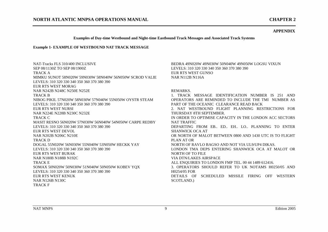
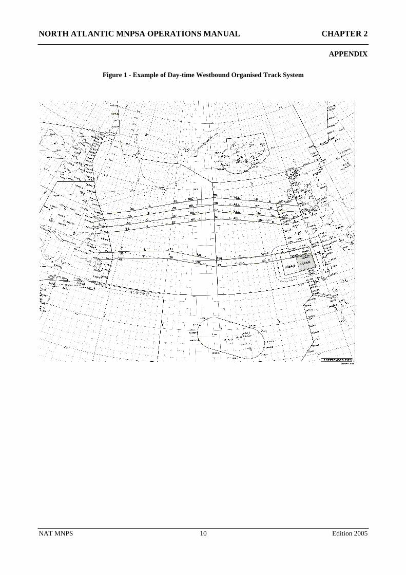
Examples of Day-time Westbound and Night-time Eastbound Track Messages and Associated Track Systems
Example 1- EXAMPLE OF WESTBOUND NAT TRACK MESSAGE
NAT-Tracks FLS 310/400 INCLUSIVE SEP 08/1130Z TO SEP 08/1900Z TRACK A MIMKU SUNOT 58N020W 59N030W 58N040W 56N050W SCROD VALIE LEVELS: 310 320 330 340 350 360 370 380 390 EUR RTS WEST MORAG NAR N242B N248C N250E N252E TRACK B NIBOG PIKIL 57N020W 58N030W 57N040W 55N050W OYSTR STEAM LEVELS: 310 320 330 340 350 360 370 380 390 EUR RTS WEST NURSI NAR N224E N228B N230C N232E TRACK C MASIT RESNO 56N020W 57N030W 56N040W 54N050W CARPE REDBY LEVELS: 310 320 330 340 350 360 370 380 390 EUR RTS WEST DEVOL NAR N202B N206C N210E TRACK D DOGAL 55N020W 56N030W 55N040W 53N050W HECKK YAY LEVELS: 310 320 330 340 350 360 370 380 390 EUR RTS WEST BURAK NAR N180B N188B N192C TRACK E SOMAX 50N020W 50N030W 51N040W 50N050W KOBEV YQX LEVELS: 310 320 330 340 350 360 370 380 390 EUR RTS WEST KENUK NAR N126B N130C TRACK F
BEDRA 49N020W 49N030W 50N040W 49N050W LOGSU VIXUN LEVELS: 310 320 330 340 350 360 370 380 390 EUR RTS WEST GUNSO NAR N112B N116A REMARKS. 1. TRACK MESSAGE IDENTIFICATION NUMBER IS 251 AND OPERATORS ARE REMINDED TO INCLUDE THE TMI NUMBER AS PART OF THE OCEANIC CLEARANCE READ BACK 2. NAT WESTBOUND FLIGHT PLANNING RESTRICTIONS FOR THURSDAY 8TH SEPTEMBER. IN ORDER TO OPTIMISE CAPACITY IN THE LONDON ACC SECTORS NAT TRAFFIC DEPARTING FROM EB.. ED.. EH.. LO.. PLANNING TO ENTER SHANWICK OCA AT OR NORTH OF MALOT BETWEEN 0800 AND 1430 UTC IS TO FLIGHT PLAN AT OR NORTH OF RAVLO BAGSO AND NOT VIA UL9/UP4 DIKAS. LONDON TMA DEPS ENTERING SHANWICK OCA AT MALOT OR NORTH OF TO FILE VIA DTN/LAKES AIRSPACE ALL ENQUIRIES TO LONDON FMP TEL. 00 44 1489 612416. 3. OPERATORS SHOULD REFER TO UK NOTAMS H0250/05 AND H0254/05 FOR DETAILS OF SCHEDULED MISSILE FIRING OFF WESTERN SCOTLAND.)
NORTH ATLANTIC MNPSA OPERATIONS MANUAL CHAPTER 2
APPENDIX
NAT MNPS 10 Edition 2005
Figure 1 - Example of Day-time Westbound Organised Track System
NORTH ATLANTIC MNPSA OPERATIONS MANUAL CHAPTER 2
APPENDIX
NAT MNPS 11 Edition 2005
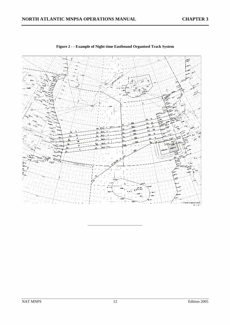
Example 2 - EXAMPLE OF EASTBOUND NAT TRACK MESSAGE
EASTBOUND TRACKS (NAT- TRACKS FLS 300/400 INCLUSIVE SEP 08/0100Z TO SEP 08/0800Z NAT-T DOTTY CRONO 52/50 54/40 55/30 56/20 PIKIL MIMKU MORAG EAST LVLS 320 330 340 350 360 370 380 390 400 WEST LVLS NIL EUR RTS EAST EHAM E223A EDDF E223A EDDM E223A EHAM E225A EDDF E225A EDDM E225A NAR N111B N113B N115B- U CYMON DENDU 51/50 53/40 54/30 55/20 RESNO NIBOG NURSI EAST LVLS 320 330 340 350 360 370 380 390 400 WEST LVLS NIL EUR RTS EAST EHAM E261A EDDF E261A EDDM E261A EHAM E263A EDDF E263A EDDM E263A NAR N95B N97B N99A- V YQX KOBEV 50/50 52/40 53/30 54/20 DOGAL BABAN EAST LVLS 320 330 340 350 360 370 380 390 400 WEST LVLS NIL EUR RTS EAST NIL NAT N79B N83B N85A- W VIXUN LOGSU 49/50 51/40 52/30 53/20 MALOT BURAK EAST LVLS 320 330 340 350 360 370 380 390 400 WEST LVLS NIL EUR RTS EAST NIL NAR N63B N67B- X YYT NOVEP 48/50 50/40 51/30 52/20 LIMRI DOLIP EAST LVLS 320 330 340 350 360 370 380 390 400 WEST LVLS NIL EUR RTS EAST NIL NAR N53B N59A- Y COLOR RONPO 47/50 49/40 50/30 51/20 DINIM GIPER
EAST LVLS 320 330 340 350 360 370 380 390 400 WEST LVLS NIL EUR RTS EAST NIL NAR N43A N49A- Z 41/40 47/30 50/20 SOMAX KENUK EAST LVLS 310 340 380 WEST LVLS NIL EUR RTS EAST NIL NAR NIL- REMARKS: 1. TRACK MESSAGE IDENTIFICATION NUMBER IS 251 AND OPERATORS ARE REMINDED TO INCLUDE THE TRACK MESSAGE IDENTIFICATION NUMBER. AS PART OF THE OCEANIC CLEARANCE READ BACK 2. CLEARANCE DELIVERY FREQUENCY ASSIGNMENTS FOR AIRCRAFT OPERATING FROM MOATT TO BOBTU INCLUSIVE: MOATT TO SCROD 128.7 OYSTR TO YAY 135.45 DOTTY TO CYMON 135.05 YQX TO YYT 128.45 COLOR TO BOBTU 119.42 3. 80 PERCENT OF GROSS NAVIGATIONAL ERRORS RESULT FROM POOR COCKPIT PROCEDURES. ALWAYS CARRY OUT PROPER WAYPOINT CHECKS. 4. NAT EASTBOUND FLIGHT PLANNING RESTRICTIONS IN FORCE REFER TO EGGX G0344/04.)
NORTH ATLANTIC MNPSA OPERATIONS MANUAL CHAPTER 3
NAT MNPS 12 Edition 2005
Figure 2 - - Example of Night-time Eastbound Organised Track System
NORTH ATLANTIC MNPSA OPERATIONS MANUAL CHAPTER 3
NAT MNPS 13 Edition 2005
Chapter 3: Other Routes and Route Structures Within or Adjacent to NAT MNPS Airspace
3.1 GENERAL
3.1.1 The Organised Track System is the most significant route structure within NAT MNPS Airspace. Other route structures within and adjacent to MNPS Airspace are detailed below.
3.2 OTHER ROUTES WITHIN NAT MNPS AIRSPACE
3.2.1 Other routes within NAT MNPS Airspace (illustrated in Fig 3) are as follows:
(1) A699 and A700 in the western part of the New York OCA;
(2)* ‘Blue Spruce’ Routes, established as special routes for aircraft equipped with only one serviceable LRNS. (Chapter 1 refers.) State approval for MNPS operations is required in order to fly along these routes. (See Chapter 10 for full route definitions);
(3) routes between Northern Europe and Spain/Canaries/Lisbon FIR. (T9*, T14 and T16);
(4)* routings between the Azores and the Portuguese mainland and between the Azores and the Madeira Archipelago;
(5) special routes of short stage lengths where aircraft equipped with normal short-range navigation equipment can meet the MNPS track-keeping criteria (G3 and G11). State approval for MNPS operations is required in order to fly along these routes.
*Note: routes identified with an asterisk in sub paragraphs (2), (3) and (4) above may be flight planned and flown by approved aircraft equipped with normal short-range navigation equipment (VOR, DME, ADF) and at least one approved fully operational LRNS.
3.3 ROUTE STRUCTURES ADJACENT TO NAT MNPS AIRSPACE
North American Routes (NARs)
3.3.1 The North American Routes (NARs) consist of a numbered series of predetermined routes which provide an interface between NAT oceanic and North American domestic airspace. The NAR System is designed to accommodate major airports in North America.
3.3.2 Full details of all NAR routings (eastbound and westbound) together with associated procedures are published in the United States Airport Facility Directory - Northeast and the Canada Flight Supplement (See http://www.naco.faa.gov/index.asp?xml=naco/catalog/charts/supplementary/af_directory and http://www.tc.gc.ca/civilaviation/regserv/Affairs/AIP/about.htm respectively). It should be noted that these routes are subject to occasional changes and are re-published/updated on a regular AIRAC 56-day cycle
NORTH ATLANTIC MNPSA OPERATIONS MANUAL CHAPTER 3
NAT MNPS 14 Edition 2005
Canadian Domestic Track Systems
3.3.3 Within Canada there are two track systems: the Northern Control Area tracks and the Southern Control Area tracks; these provide links for NAT traffic operating between Europe and North America to central and western North American airports. Track procedures and details are published in AIP Canada.
Routes between North America and the Caribbean area
3.3.4 An extensive network of routes linking points in the United States and Canada with Bermuda, the Bahamas and the Caribbean area are defined in the New York OCA to the west of 60°W. This network is known as the Western Atlantic Route System (WATRS). Details of these routes and associated procedures are contained in the United States AIP.
Irish/UK Domestic Route Structures
3.3.5 The UK AIP and AIP Ireland both specify the domestic routes to be used for westbound NAT traffic, based upon entry points into oceanic airspace.
North Atlantic European Routing Scheme (NERS)
3.3.6 Previous flight planning arrangements for the European domestic route portion of eastbound NAT flights were superseded in February 2005 by Phase 1 of the NERS. Later Phases will also include westbound routings. The NERS is similar in concept to the NARS which has been in use in North America by NAT traffic for many years. The NERS consists of a numbered series of predetermined routes which provide an interface between NAT oceanic and European domestic airspace. The NER system is designed to accommodate major airports in Europe.
3.3.7 The NERS valid for a particular day will be published on the track signal but will only be used when the traffic density warrants their use. They are not expected to be published every day. Full details of all NER routings together with associated procedures are published in CFMU Route Availabilty Document Annex NAT (www.cfmu.eurocontrol.int/rad/).
Shannon Oceanic Transition Area (SOTA)
3.3.8 Part of the Shanwick OCA is designated as the Shannon Oceanic Transition Area (SOTA). MNPS Airspace requirements are still applicable from FL285 to FL420. SOTA has the same vertical extent as the Shanwick OCA, and is bounded by lines joining successively the following points:
N5100 W01500 – N5100 W00800 – N4830 W00800 – N4900 W01500 – N5100 W01500
3.3.9 Air Traffic Service is provided by Shannon ACC using the call sign SHANNON CONTROL. Full details of the service provided and the procedures used are contained in AIP Ireland.
Northern Oceanic Transition Area (NOTA)
3.3.10 Similar to the long established SOTA, since early 2005, a further part of Shanwick OCA has been designated as the Northern Oceanic Transition Area NOTA.
3.3.11 MNPS requirements are still applicable from FL 285 to FL 420. NOTA has the same vertical extent as the Shanwick OCA and is bounded by the lines joining successively the following points.
N5400 W01500 - N5700 W01500 - N5700 W01000W - N5434 W01000 - N5400 W01500.
NORTH ATLANTIC MNPSA OPERATIONS MANUAL CHAPTER 3
NAT MNPS 15 Edition 2005
3.3.12 Air Traffic service is provided by Shannon ACC using the callsign SHANNON CONTROL. Full details of the service provided and the procedures used are contained in AIP Ireland and AIP UK. (N.B. For an interim period, westbound aircraft entering the NOTA are required to obtain an oceanic clearance from Shanwick at least 40 minutes prior to crossing KORIB, MASIT, NIBOG or MIMKU. This interim period is expected to continue until Autumn 2006. Termination of interim procedures will be notified by NOTAM.)
Brest Oceanic Transition Area (BOTA)
3.3.13 Part of the Shanwick OCA is designated as the Brest Oceanic Transition Area (BOTA). MNPS Airspace requirements are still applicable from FL285 to FL420. BOTA has the same vertical extent as the Shanwick OCA, and is bounded by lines joining successively the following points:
N4834 W00845 – N4830 W00800 – N4500 W00800 – N4500 W00845 – N4834 W00845
3.3.14 Air Traffic service is provided by the Brest ACC, call sign BREST CONTROL.
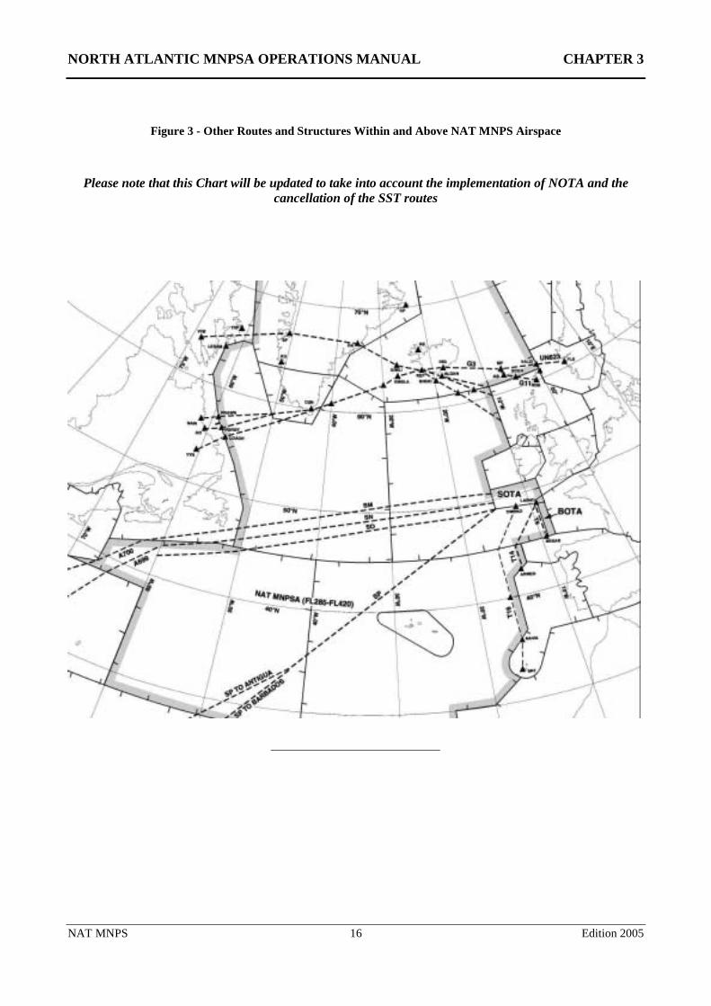
NORTH ATLANTIC MNPSA OPERATIONS MANUAL CHAPTER 3
NAT MNPS 16 Edition 2005
Figure 3 - Other Routes and Structures Within and Above NAT MNPS Airspace
Please note that this Chart will be updated to take into account the implementation of NOTA and the cancellation of the SST routes
NORTH ATLANTIC MNPSA OPERATIONS MANUAL CHAPTER 4
NAT MNPS 17 Edition 2005
Chapter 4: Flight Planning
4.1 FLIGHT PLAN REQUIREMENTS
General
4.1.1 It is essential that care is taken when feeding track information into a computer and the information should be cross-checked before it is given to the operating crew. Crews of all NAT MNPSA flights, even those that are not planned to use the OTS, should be given both the organised track message and relevant amendments to it. (N.B. In the event of a contingency or diversion, knowledge of the location of the OTS tracks will be useful to the crew of any NAT MNPSA flight). Should more than one version of the daily Track Message have been issued, then crews should be issued the entire revised version together with an appropriate explanation to relate differences between versions. Each successive version will be identified by the TMI and an alphabetic suffix. e.g. 243A, 243B etc.
4.1.2 All flights which generally route in an eastbound or westbound direction should normally be flight planned so that specified ten degrees of longitude (20°W, 30°W, 40°W etc.) are crossed at whole degrees of latitude; and all generally northbound or southbound flights should normally be flight planned so that specified parallels of latitude spaced at five degree intervals (65°N, 60°N, 55°N etc.) are crossed at whole degrees of longitude. (N.B. For those flights that generally route in an eastbound or westbound direction, it is important that the latitude crossings of ALL oceanic ten-degree meridians be included as waypoints in the flight plan submitted to ATC. Even where “named” significant points are close to these "prime" meridians of longitude it is not appropriate to omit the ten-degree crossings from the ATC Flight Plan.).
4.1.3 All flights should plan to operate on great circle tracks joining successive significant waypoints.
Routings
4.1.4 During the hours of validity of the OTS, operators are encouraged to flight plan as follows:
• in accordance with the OTS; or
• along a route to join or leave an outer track of the OTS; or
• on a random route to remain clear of the OTS
4.1.5 Nothing in the paragraph above prevents operators from flight planning across the OTS. However they should be aware that whilst ATC will make every effort to clear random traffic across the OTS at published levels, re-routes or significant changes in flight level are likely to be necessary during most of the OTS traffic periods.
4.1.6 Outside of the OTS periods operators may flight plan any random routing, except that during the two hours prior to each OTS period the following restrictions apply:
(1) eastbound flights that cross 30°W less than one hour prior to the incoming/pending westbound OTS (i.e. after 1029 UTC), or westbound flights that cross 30°W less than one hour prior to the incoming/pending eastbound OTS (i.e. after 2359 UTC), should plan to remain clear of the incoming/pending OTS structure.
NORTH ATLANTIC MNPSA OPERATIONS MANUAL CHAPTER 4
NAT MNPS 18 Edition 2005
(2) any such opposite direction flights crossing 30oW between one and two hours prior to the incoming/pending OTS (i.e. any eastbound flights between 0930 and 1029 UTC, or any westbound flights between 2300 and 2359 UTC) where the route beyond 30°W would coincide with the incoming/pending OTS structure at any point, should plan to join an outer track at any point, or backtrack the length of one of the incoming/pending tracks.
Flight Levels
4.1.7 Within RVSM Airspace greater opportunity exists for step climbs. Operators may include step climbs in the flight plan, although each change of level during flight must be requested from ATC by the pilot. The chance of approval of such requests will, of course, be entirely dependent upon potential traffic conflicts. Outside the OTS there is a good likelihood of achieving the requested profiles. However, within the prime OTS levels at peak times, ATC may not always be able to accommodate requested flight level changes and prudent pre-flight fuel planning should take this into consideration.
4.1.8 During the OTS Periods (eastbound 0100-0800 UTC, westbound 1130-1900 UTC) aircraft intending to follow an OTS Track for its entire length may plan at any of the levels as published for that track on the current daily OTS Message. Flights which are planned to remain entirely clear of the OTS or which join or leave an OTS Track (i.e. follow an OTS track for only part of its published length), are all referred to as Random Flights. Pilots intending to fly on a random route or outside the OTS time periods, should normally plan flight level(s) appropriate to the direction of flight.
Note: “Appropriate Direction Levels” within the NAT MNPSA are specified by the Semi-circular Rule Per ICAO Annex 2, Appendix 3, Table a):
4.1.9 Planners should note however that the AIPs specify some exceptions to use of “Appropriate Direction Levels” both during the OTS time periods and outside them. At specified times, appropriate direction levels are reserved for use by (opposite direction) traffic flows that then predominate. These exceptions may be modified in future to accommodate changes in traffic flows. The current usage allocation of flight levels in the NAT MNPSA is published in the UK and Canadian AIPs as the NAT Flight Level Allocation Scheme (FLAS). Hence, pilots and planners should always consult the current AIPs and any supporting NOTAMs when flight planning random routes through NAT MNPS Airspace.
4.1.10 If a flight is expected to be level critical, operators should contact the initial OAC prior to filing of the flight plan to determine the likely availability of specific flight levels.
ATC Flight Plans
4.1.11 Correct completion and addressing of the flight plan is extremely important as errors can lead to delays in data processing and to the subsequent issuing of clearances to the flights concerned. Despite the growing use of automated flight planning systems a significant proportion of ATC Flight Plans submitted in respect of flights through the North Atlantic Region continue to contain errors. In some instances these errors are such that the Flight Plan is rejected and the Operator is required to re-submit a corrected version. Full and detailed explanations of how to complete an ATS Flight Plan in respect of the NAT portion of a flight are contained in the NAT Flight Planning Guidance Material (available at http://www.nat-pco.org/ ). This document also highlights the more common completion errors that are made. UK AIC 55/2003 provides similar NAT Region specific guidance and includes example completed ICAO Flight Plans. A copy of this AIC may be downloaded from the NAT PCO website http://www.nat-pco.org/. New and/or infrequent North Atlantic operators are earnestly recommended to make diligent reference to these documents.
NORTH ATLANTIC MNPSA OPERATIONS MANUAL CHAPTER 4
NAT MNPS 19 Edition 2005
4.1.12 In order to signify that a flight is approved to operate in NAT MNPS Airspace, the letter ‘X’ shall be inserted, in addition to the letter ‘S’, within Item 10 of the flight plan. A ‘W’ must also be included in Item 10 to indicate that the flight is approved for RVSM operations.
4.1.13 For turbojet aircraft the Mach Number planned to be used for each portion of the flight in the NAT Region should be specified in Item 15 of the flight plan.
4.1.14 Item 15 of the flight plan should reflect the proposed speeds in the following sequence:
• cruising True Airspeed (TAS);
• oceanic entry point and cruising Mach Number;
• oceanic landfall and cruising TAS.
4.2 FLIGHT PLANNING REQUIREMENTS ON SPECIFIC ROUTES
(Full details are contained in the NAT FP GM (available at http://www.nat-pco.org/ )
Flights Planning on the Organised Track System
4.2.1 If (and only if) the flight is planned to operate along the entire length of one of the organised tracks, from oceanic entry point to oceanic exit point, as detailed in the NAT Track Message, should the intended organised track be defined in Item 15 of the flight plan using the abbreviation 'NAT' followed by the code letter assigned to the track.
4.2.2 Flights wishing to join or leave an organised track at some intermediate point are considered to be random route aircraft and full route details must be specified in the flight plan. The track letter must not be used to abbreviate any portion of the route in these circumstances.
4.2.3 The planned Mach Number and flight level for the organised track should be specified at either the last domestic reporting point prior to oceanic airspace entry or the organised track commencement point.
4.2.4 Each point at which a change of Mach Number or flight level is planned must be specified by geographical co-ordinates in latitude and longitude or as a named waypoint.
4.2.5 For flights operating along the whole length of one of the organised tracks, estimates are only required for the commencement point of the track.
Flights Planning on Random Route Segments in a Generally Eastbound or Westbound Direction at/or South of 70°N
4.2.6 The requested Mach Number and flight level should be specified at either the last domestic reporting point prior to oceanic airspace entry or the OCA boundary.
4.2.7 The route of flight should be specified in terms of the following significant points, with estimates included in Item 18 of the flight plan:
(1) the last domestic reporting point prior to the oceanic entry point;
(2) the OCA boundary entry point (only required by the Gander, Shanwick, New York and Santa Maria OACs);
NORTH ATLANTIC MNPSA OPERATIONS MANUAL CHAPTER 4
NAT MNPS 20 Edition 2005
(3) significant points formed by the intersection of half or whole degrees of latitude, with meridians spaced at intervals of ten degrees of longitude from the Zero degree E/W (Greenwich) Meridian to longitude 70°W;
(4) the OCA boundary exit point (only required by the Gander, Shanwick, New York and Santa Maria OACs); and
(5) the first domestic reporting point after ocean exit.
4.2.8 Each point at which a change of Mach Number or flight level is requested must be specified and followed in each case by the next significant point.
Flights Planning on a Generally Eastbound or Westbound Direction on Random Route Segments North of 70°N
4.2.9 Flight planning requirements for flights in this category are identical to those listed for flights on random route segments at/or south of 70°N except that a route should be specified in terms of significant points formed by the intersection of parallels of latitude expressed in degrees and minutes with meridians normally spaced at intervals of 20° from the Zero degree E/W (Greenwich ) Meridian to longitude 60°W.
Flights Planning on Random Routes in a Generally Northbound or Southbound Direction
Note : The ICAO Regional Supplementary Procedures for the NAT Region (Doc.7030) state that flights operating between North America and Europe shall generally be considered as operating in a predominantly east-west direction. However, flights planned between these two continents via the North Pole shall be considered as operating in a predominantly north-south direction.
4.2.10 Flight planning requirements for flights in this category are identical to those listed for flights operating on random route segments at/or south of 70°N except that the route should be specified in terms of significant points formed by the intersection of whole degrees of longitude with specified parallels of latitude which are spaced at 5° intervals from 20°N to 90°N.
Flights Planning to Operate Without HF Communications
4.2.11 The carriage of HF communications is mandatory for flight in the Shanwick OCA. Aircraft with only functioning VHF communications equipment should plan their route outside the Shanwick OCA and ensure that they remain within VHF coverage of appropriate ground stations throughout the flight. Theoretical VHF coverage charts are included in ICAO NAT Doc 001. Such strict routing restriction may not apply in all NAT Oceanic Control Areas. Some may permit the use of SATCOM Voice to substitute for or supplement HF communications. Details of communication requirements by individual NAT ATS Providers are published in State AIPs. However, it must also be recognised that the Safety Regulator of the operator may impose its own operational limitations on SATCOM Voice usage. Any operator intending to fly through NAT MNPS Airspace without fully functional HF communications should ensure that it will meet the requirements of its State of Registry and those of all the relevant ATS Providers throughout the proposed route.
NORTH ATLANTIC MNPSA OPERATIONS MANUAL CHAPTER 5
NAT MNPS 21 Edition 2005
Chapter 5: Oceanic ATC Clearances
5.1 GENERAL
5.1.1 Oceanic Clearances are required for all flights within NAT controlled Airspace (at or above FL55). Pilots should request Oceanic Clearances from the ATC unit responsible for the first OCA within which they wish to operate, following the procedures and the time-frame laid down in appropriate AIPs. Such clearances, although in most cases obtained some time before reaching the Oceanic entry point, are applicable only from that entry point. It is recommended that pilots should request their Oceanic Clearance at least 40 minutes prior to the Oceanic entry point ETA and, if requesting an OTS track, should include the next preferred alternative.
5.1.2 When requesting an oceanic clearance the pilot should notify the OAC of the maximum acceptable flight level possible at the boundary, taking into account that a climb to the assigned oceanic flight level must be achieved prior to entering oceanic airspace and normally whilst the aircraft is within radar coverage. The pilot should also notify the OAC of any required change to the oceanic flight planned level, track or Mach Number as early as practicable after departure to assist the OAC in pre-planning optimum airspace utilisation.
5.1.3 Specific information on how to obtain oceanic clearance from each NAT OAC is published in State AIPs. Various methods of obtaining Oceanic Clearances include:
(1) use of published VHF clearance delivery frequencies;
(2) by HF communications to the OAC through the appropriate aeradio station (at least 40 minutes before boundary/entry estimate);
(3) a request via domestic or other ATC agencies;
(4) by data link, when arrangements have been made with designated airlines to request and receive clearances using on-board equipment (ACARS). This method of Oceanic Clearance delivery is only possible from participating OACs with the necessary means of automation. Detailed procedures for its operation may vary. Gander and Shanwick OACs have been providing such a facility for a number of years and the relevant operational procedures are available for download from the NAT PCO website (see http://www.nat-pco.org/). Reykjavik and Santa Maria OACs anticipate offering such an ACARS-based service in the near future. New York OAC expects to use the FANS 1/A CPDLC function to uplink some oceanic clearances.
5.1.4 At some airports situated close to oceanic boundaries, the Oceanic Clearance must be obtained before departure (e.g. from Prestwick, Shannon, Glasgow, Dublin, Belfast, Edinburgh, Bristol, Gander, Goose Bay, and St Johns). Indeed on the east side of the NAT this will apply to departures from all Irish airfields, all UK airfields west of 2° 30'W and all French Airfields west of zero degree longitude. Oceanic Clearances for controlled flights leaving airports within the region are issued by the relevant ATS unit prior to departure.
5.1.5 If an aircraft, which would normally be RVSM and/or MNPS approved, encounters, whilst en route to the NAT Oceanic Airspace, a critical in-flight equipment failure, or at dispatch is unable to meet the MEL requirements for RVSM or MNPS approval on the flight, then the pilot must advise ATC at initial contact when requesting Oceanic Clearance.
NORTH ATLANTIC MNPSA OPERATIONS MANUAL CHAPTER 5
NAT MNPS 22 Edition 2005
5.1.6 After obtaining and reading back the clearance, the pilot should monitor the forward estimate for oceanic entry, and if this changes by 3 minutes or more, should pass a revised estimate to ATC. As planned longitudinal spacing by these OACs is based solely on the estimated times over the oceanic entry fix or boundary, failure to adhere to this ETA amendment procedure may jeopardise planned separation between aircraft, thus resulting in a subsequent re-clearance to a less economical track/flight level for the complete crossing. Any such failure may also penalise following aircraft.
5.1.7 If any of the route, flight level or Mach Number in the clearance differs from that flight planned, requested or previously cleared, attention may be drawn to such changes when the clearance is delivered (whether by voice or by datalink). Pilots should pay particular attention when the issued clearance differs from the Flight Plan. (N.B. a significant proportion of navigation errors investigated in the NAT involve an aircraft which has followed its Flight Plan rather than its differing clearance).
5.1.8 Furthermore it must be recognised that if the entry point of the oceanic route on which the flight is cleared differs from that originally requested and/or the oceanic flight level differs from the current flight level, the pilot is responsible for requesting and obtaining the necessary domestic re-clearance to ensure that the flight is in compliance with its Oceanic Clearance when entering oceanic airspace.
5.1.9 There are three elements to an Oceanic Clearance: route, Mach Number and flight level. These elements serve to provide for the three basic elements of separation: lateral, longitudinal and vertical.
5.1.10 The Oceanic Clearance issued to each aircraft is at a specific flight level and cruise Mach Number. Flight level or Mach Number changes should not normally be made without prior ATC clearance. (See Chapter 7 for Application of Mach Number Technique.)
5.1.11 If pilots have not received their Oceanic Clearance prior to reaching the Shanwick OCA boundary, they must contact Domestic ATC and request instructions to enable them to remain clear of Oceanic Airspace whilst awaiting such Clearance. This is not the case for other NAT OCAs into any of which flights may enter whilst pilots are awaiting receipt of a delayed Oceanic Clearance. Pilots should always endeavour to obtain Oceanic Clearance prior to entering these other NAT OCAs; however if any difficulty is encountered the pilot should not hold while awaiting Clearance unless so directed by ATC. In such circumstances, pending receipt of the Oceanic Clearance, the aircraft should continue to maintain the flight level cleared by the current control authority.
5.1.12 An example of a pilot voice request for Oceanic Clearance is as follows:
“ACA 865 request Oceanic Clearance. Estimating 56N010W at 1131. Request Mach decimal eight zero, Flight Level three five zero, able Flight Level three six zero, second choice Track Charlie”.
5.1.13 If the request also includes a change to the original flight plan, affecting the OCA, then it should be according to the following example:
“BAW 123 request Oceanic Clearance. Estimating 55N010W at 1147. Request Mach decimal eight zero, Flight Level three four zero. Now requesting Track Charlie, able Flight Level three six zero, second choice Track Delta”.
5.2 CONTENTS OF CLEARANCES
5.2.1 An abbreviated clearance is issued by Air Traffic Services when clearing an aircraft to fly along the whole length of an Organised Track. When an abbreviated clearance is issued it includes:
• clearance Limit, which will normally be destination airfield;
NORTH ATLANTIC MNPSA OPERATIONS MANUAL CHAPTER 5
NAT MNPS 23 Edition 2005
• cleared track specified as “Track” plus code letter;
• cleared flight level(s);
• cleared Mach Number; and
• if the aircraft is designated to report MET information en route, the phrase “SEND MET REPORTS”.
5.2.2 Procedures exist for an abbreviated read back of an Oceanic Clearance issued on VHF. A typical example of such a clearance is as follows:
“ACA865 is cleared to Toronto via Track Bravo, from 56N010W maintain Flight Level three five zero, Mach decimal eight zero”.
5.2.3 The flight crew will confirm that they are in possession of the current NAT Track message by using the TMI number (including any appropriate alpha suffix) in the read-back of the Oceanic Clearance, as follows:
“ACA865 is cleared to Toronto via Track Bravo 283A, from 56N010W maintain Flight Level three five zero, Mach decimal eight zero”.
5.2.4 If the TMI number is included in the read-back there is no requirement for the pilot to read back the NAT Track co-ordinates even if the cleared NAT Track is not the one which was originally requested. If any doubt exists as to the TMI (see fuller explanation of this term in Chapter 2,, paragraph 2.3.3) or the NAT Track co-ordinates, the pilot should request the complete track co-ordinates from the OAC. Similarly, if the pilot cannot correctly state the TMI, the OAC will read the cleared NAT Track co-ordinates in full and request a full read back of those co-ordinates.
5.2.5 For aircraft cleared by Shanwick OAC on random routings in the NAT Region the present procedure of reading the full track co-ordinates as part of the Oceanic Clearance and requesting from the pilot a full read back of the co-ordinates is expected to continue. Gander and Reykjavik OACs may, however, issue clearances for random routings which specify “via flight plan route”. Nevertheless, in all circumstances regarding random route clearances, pilots are required to read back the full track co-ordinates of the flight plan route, from the oceanic entry point to the exit point.
5.3 OCEANIC CLEARANCES FOR WESTBOUND FLIGHTS ROUTING VIA 61°N 010°W
5.3.1 The provision of air traffic service at RATSU (61°N 010°W) has been delegated by Shanwick to Reykjavik. Flights intending to route via RATSU (61°N 010°W) should not call Shanwick for an Oceanic Clearance. The required Oceanic Clearance will be issued by Reykjavik Control. There are three points established at the boundary of delegated airspace from Scottish to Reykjavik, BESGA, DEVBI and BARKU on routes to RATSU. Reykjavik will issue Oceanic Clearances from those points. Aircraft that have not received their oceanic clearance prior those points shall enter Reykjavik airspace at the domestic cleared flight level while awaiting such oceanic clearance.
5.4 OCEANIC CLEARANCES FOR FLIGHTS INTENDING TO OPERATE WITHIN THE NAT REGION AND SUBSEQUENTLY ENTER THE EUR OR NAM REGIONS
5.4.1 Oceanic Clearances issued to most flights in this category are strategic clearances intended to provide a safe separation for each flight, from oceanic entry to oceanic track termination point. Should a pilot receive a clearance on a track other than originally flight planned, special caution should be exercised to ensure that the co-ordinates of the assigned track and of the associated landfall and domestic routings are
NORTH ATLANTIC MNPSA OPERATIONS MANUAL CHAPTER 5
NAT MNPS 24 Edition 2005
fully understood and correctly inserted into the automated navigation system. Appropriate cross checks should be carried out. In all cases when an en route re-clearance is requested, the pilot should ensure that the revised ATC clearance includes the new routing from the oceanic exit point to the first landfall point or coastal fix. If at the time of being given a clearance or re-clearance, the pilot has any doubt, details should be checked with the ATC unit issuing the clearance/re-clearance.
5.5 OCEANIC CLEARANCES FOR RANDOM FLIGHTS INTENDING TO OPERATE WITHIN THE NAT REGION AND SUBSEQUENTLY ENTER REGIONS OTHER THAN NAM OR EUR
5.5.1 Oceanic Clearances issued to flights in this category are similar to domestic ATC clearances in that clearances are to destination on the assumption that co-ordination will be effected ahead of the aircraft's passage. In this case, the flight profile may be changed en route, prior to hand-over from one centre to another, depending upon traffic conditions in the adjacent area.
5.6 OCEANIC FLIGHTS ORIGINATING FROM THE CAR OR SAM REGIONS AND ENTERING NAT MNPS AIRSPACE VIA THE NEW YORK OCA
5.6.1 If a pilot has received the three clearance elements. i.e. a complete route, altitude, and Mach Number, even if these elements are not issued at the same time, then the pilot has been provided with an Oceanic Clearance and no request for one is necessary. For example: on a flight from Santo Domingo to Europe, Santo Domingo ACC issues a Clearance with a complete route and altitude; later, San Juan CERAP issues the aircraft a clearance to maintain Mach 0.84. At this point, all three required elements (route, Mach Number and flight level) have been received and the flight has an Oceanic Clearance. Subsequent changes to any single element of the Oceanic Clearance does not alter the others.
5.6.2 If the pilot has not received all three elements of an Oceanic Clearance, then a full Oceanic Clearance should be obtained prior to entering MNPS Airspace. If any difficulty is encountered obtaining the elements of the Oceanic Clearance, the pilot should not hold while awaiting a Clearance unless so instructed by ATC. The pilot should proceed on the cleared route into MNPS Airspace and continue to request the Clearance elements needed.
5.7 ERRORS ASSOCIATED WITH OCEANIC CLEARANCES
5.7.1 Navigation errors associated with Oceanic Clearances fall into several categories of which the most significant are ATC System Loop errors and Waypoint Insertion errors.
ATC System Loop Errors
5.7.2 An ATC system loop error is any error caused by a misunderstanding between the pilot and the controller regarding the assigned flight level, Mach Number or route to be followed. Such errors can arise from incorrect interpretation of the NAT Track Message by dispatchers; errors in co-ordination between OACs; or misinterpretation of Oceanic Clearances or re-clearances by pilots. Errors of this nature, which are detected by ATC from pilot position reports will normally be corrected. However, timely ATC intervention cannot always be guaranteed, especially as it may depend on HF communications.
Waypoint Insertion Errors
5.7.3 Experience has shown that many of the track keeping errors which occur result from:
• failure to observe the principles of checking waypoints to be inserted in the navigation systems, against the ATC cleared route;
NORTH ATLANTIC MNPSA OPERATIONS MANUAL CHAPTER 5
NAT MNPS 25 Edition 2005
• failure to load waypoint information carefully; or
• failure to cross-check on-board navigation systems.
5.7.4 More detailed guidance on this subject is contained in Chapter 8, Chapter 13 and Chapter 14 of this Document.
5.7.5 Many of the navigation error occurrences are the product of one or both of the foregoing causes. It is therefore extremely important that pilots double check each element of the Oceanic Clearance on receipt, and at each waypoint, since failure to do so may result in inadvertent deviation from cleared route and/or flight level.
NORTH ATLANTIC MNPSA OPERATIONS MANUAL CHAPTER 6
NAT MNPS 26 Edition 2005
Chapter 6: Communications and Position Reporting Procedures
6.1 ATS COMMUNICATIONS
HF Voice Communications
6.1.1 Most NAT air/ground communications are conducted on single side-band HF frequencies. Pilots communicate with OACs via aeradio stations staffed by communicators who have no executive ATC authority. Messages are relayed, from the ground station to the air traffic controllers in the relevant OAC for action.
6.1.2 In the North Atlantic Region there are six aeronautical radio stations, one associated with each of the Oceanic Control Areas. They are: Bodo Radio (Norway, Bodo ACC), Gander Radio (Canada, Gander OACC), Iceland Radio (Iceland, Reykjavik ACC), New York Radio (USA, New York OACC), Santa Maria Radio (Portugal, Santa Maria OACC) and Shanwick Radio (Ireland, Shanwick OACC). However, the aeradio stations and OACs are not necessarily co-located. For example in the case of Shanwick operations, the OAC is located at Prestwick in Scotland whilst the associated aeradio station is at Ballygirreen in the Republic of Ireland. In addition to those six aeronautical stations, there are two other stations that operate NAT frequencies. They are Canarias Radio which serves Canarias ACC and Arctic Radio serving Edmonton, Winnipeg and Montreal ACC’s.
6.1.3 To support air/ground ATC communications in the North Atlantic Region, twenty-four HF frequencies have been allocated, in different bands (ranging from 2.8 to 18 MHz). There are a number of factors which affect the optimum frequency for communications over a specific path. The most significant is the diurnal variation in intensity of the ionisation of the refractive layers of the ionosphere. Hence frequencies from the lower HF bands tend to be used for communications during night-time and those from the higher bands during day-time. Generally in the North Atlantic frequencies of less than 7 MHz are utilised at night and frequencies greater than 8 MHz during the day. The 24 NAT frequencies are organized into six groups known as Families. The families are identified as NAT Family A, B, C, D, E and F. Each Family contains a range of frequencies from each of the HF frequency bands. A number of stations share families of frequencies and co-operate as a network to provide the required geographical and time of day coverage.. A full listing of the frequency hours of operation of each NAT aeradio station is contained in the “HF Management Guidance Material for the NAT Region” – ICAO NAT Doc.003 (Appendices 1 thru 6), available via the NAT-PCO website at http://www.nat-pco.org . Each Family is designated for use by aircraft of specific States of Registry and according to the route to be flown. NAT ATS provider State AIPs list the families of frequencies to be used.
6.1.4 Each individual aircraft is normally allocated a primary and a secondary HF frequency, either when it receives its clearance or by domestic controllers shortly before the oceanic boundary.
6.1.5 When initiating contact with an aeradio station the pilot should state the HF frequency in use. HF Radio operators usually maintain a listening watch on more than one single frequency. Identification by the calling pilot of the particular frequency being used, is helpful to the radio operator.
SELCAL
6.1.6 When using HF communications and even when using ADS and/or CPDLC, pilots should maintain a listening watch on the assigned frequency, unless SELCAL is fitted, in which case they should ensure the following sequence of actions:
NORTH ATLANTIC MNPSA OPERATIONS MANUAL CHAPTER 6
NAT MNPS 27 Edition 2005
(1) provision of the SELCAL code in the flight plan; (any subsequent change of aircraft for a flight will require passing the new SELCAL information to the OAC);
(2) checking the operation of the SELCAL equipment, at or prior to entry into Oceanic airspace, with the appropriate aeradio station. (This SELCAL check must be completed prior to commencing SELCAL watch); and
(3) maintenance thereafter of a SELCAL watch
6.1.7 It is important to note that it is equally essential to comply with the foregoing SECAL provisions even if ADS and/or CPDLC are being used for routine air/ground ATS communications. This will ensure that ATC has a means of contacting the aircraft even if data communications fail.
Twelve Tone SELCAL
6.1.8 Flight management staffs and crews of aircraft equipped with 12-tone SELCAL equipment should be made aware that SELCAL code assignment is predicated on the usual geographical area of operation of that aircraft. If the aircraft is later flown in geographical areas other than as originally specified by the aircraft operator, the aircraft may encounter a duplicate SELCAL code situation. Whenever an aircraft is to be flown routinely beyond the area of normal operations or is changed to a new geographic operating area, the aircraft operator should contact the SELCAL Registrar and request a SELCAL code appropriate for use in the new area.
6.1.9 When acquiring a previously owned aircraft equipped with SELCAL, many aircraft operators mistakenly assume that the SELCAL code automatically transfers to the purchaser or lessee. This is not true. As soon as practical, it is the responsibility of the purchaser or lessee to obtain a SELCAL code from the Registrar, or, if allocated a block of codes for a fleet of aircraft, to assign a new code from within the block of allocated codes. In the latter instance, if 12-tone equipment is involved, the Registrar should be consulted when there is any question as to the likely geographical area of operation and the possibility of code duplication.
6.1.10 The registrar can be contacted via the AFTN address KDCAXAAG, and by including “ATTN. OPS DEPT. (forward to SELCAL Registrar)” as the first line of message text.
VHF Voice Communications
6.1.11 Aeradio stations are also responsible for the operation of General Purpose VHF (GP/VHF) outlets. North Atlantic flights may use these facilities for all regular and emergency communications with relevant OACs. Such facilities are especially valuable in the vicinity of Iceland, Faroes and Greenland since VHF is not as susceptible to sunspot activity as HF. Outlets are situated at Prins Christian Sund, which is remotely controlled from Gander Aeradio station, and at Qaqatoqaq, Kulusuk and the Faroes, via Iceland Radio. Theoretical VHF coverage charts are included in the ICAO publication NAT Doc 001 (available for download at http://www.nat-pco.org/). When using GP/VHF frequencies in areas of fringe coverage however, care should be taken to maintain a SELCAL watch on HF thus ensuring that if VHF contact is lost the aeradio station is still able to contact the aircraft. It is important for the pilot to appreciate that when using GP/VHF communications they are with an aeradio station and not by direct contact with ATC. However Direct Controller/Pilot Communications (DCPC) can be arranged if necessary on some GP/VHF frequencies.
6.1.12 The carriage of HF communications equipment is mandatory for flight in the Shanwick OCA. Aircraft with only functioning VHF communications equipment should plan their route outside the Shanwick OCA and ensure that they remain within VHF coverage of appropriate ground stations throughout the flight.. Details of communication requirements are published in State AIPs and ICAO publications.
NORTH ATLANTIC MNPSA OPERATIONS MANUAL CHAPTER 6
NAT MNPS 28 Edition 2005
SATCOM Voice Communications
6.1.13 SATCOM ATS air/ground voice communications are in various stages of trial and/or implementation in all the North Atlantic OCAs. State AIPs contain the necessary telephone numbers and/or short-codes for air-initiated call access to aeradio stations and/or direct to OACs. Procedures and rules governing the use of SATCOM Voice for regular or emergency communications are continually developing as trials proceed. Currently, SATCOM may be used by any equipped aircraft in emergency or non-routine situations. An unforeseen inability to communicate by HF is deemed to constitute such a non-routine situation. Since oceanic traffic typically communicate with ATC through aeradio facilities, a SATCOM call made due to unforeseen inability to communicate by other means should be made to such a facility rather than the ATC Centre, unless the urgency of the communication dictates otherwise. In addition to this, trials are presently being conducted in which equipped International General Aviation (IGA) aircraft may provide waypoint position reports to NAT aeradio facilities via SATCOM. IGA Operators wishing to participate in these trials must pre-register. Full details of the trials are contained in the document “Guidance Material for SATCOM WPR Trials in NAT Airspace” available at http://www.nat-pco.org/ . It is expected that these trials will be progressively expanded in the future to include all suitably equipped aircraft operating in the Region and to include all regular ATS communications. Operators are, of course, also bound by their own State of Registry’s regulations regarding carriage and use of any and all long-range ATS communications equipment. In many instances MMEL remarks for HF systems now provide significant relief for SATCOM equipped aircraft, thereby making the requirement for the carriage of fully serviceable HF communications equipment much less of an issue (Reference HF Communications Failure).
Datalink Communications
6.1.14 Datalink communications are gradually being introduced into the NAT environment for position reporting ( via FANS 1/A ADS & CPDLC and also via FMC WPR through ACARS) and for other air/ground ATS exchanges (using FANS 1/A CPDLC). Guidance Material containing full details of the various services and operational procedures can be downloaded from http://www.nat-pco.org/ . AIS publications of the NAT ATS Provider States should be consulted to determine the extent of current implementation in each of the North Atlantic OCAs. N.B. The first such datalink initiative in the North Atlantic Region, Centralised ADS (CADS) was phased out on 31 May 2005. From that date aircraft intending to provide ADS position reports must logon specifically to the initial OAC and additionally the crews are now required to be also trained for CPDLC operation.
6.1.15 On first contact with the initial aeradio stations crews of participating aircraft should expect to receive the instruction “VOICE POSITION REPORTS NOT REQUIRED”.
6.2 INTER-PILOT AIR-TO-AIR VHF FACILITY 123.45 MHz and EMERGENCY FREQUENCY 121.5 MHz
6.2.1 An air-to-air VHF frequency has been established for world-wide use when aircraft are out of range of VHF ground stations which utilise the same or adjacent frequencies. This frequency, 123.45 MHz, is intended for pilot-to-pilot exchanges of operationally significant information (N.B. It is not to be used as a “chat” frequency).
6.2.2 123.45 MHz may be used to relay position reports via another aircraft in the event of an air-ground communications failure. If necessary initial contact for such relays can be established on 121.5 MHz - although great care must be exercised should this be necessary, as the frequency 121.5 MHz is to be monitored by all aircraft operating in the NAT Region in case it is being used by aircraft experiencing emergencies.
6.2.3 Therefore in order to minimise unnecessary use of 121.5 MHz, it is recommended that aircraft additionally monitor 123.45 MHz when flying through NAT airspace.
NORTH ATLANTIC MNPSA OPERATIONS MANUAL CHAPTER 6
NAT MNPS 29 Edition 2005
6.3 POSITION REPORTING
Time and Place of Position Reports
6.3.1 Unless otherwise requested by Air Traffic Control, position reports from flights on routes which are not defined by designated reporting points should be made at the significant points listed in the flight plan.
6.3.2 Air Traffic Control may require any flight operating in a North/South direction to report its position at any intermediate parallel of latitude when deemed necessary.
6.3.3 In requiring aircraft to report their position at intermediate points, ATC is guided by the requirement to have positional information at approximately hourly intervals and also by the need to cater for varying types of aircraft and varying traffic and MET conditions.
6.3.4 If the estimated time for the ‘next position’, as last reported to ATC, has changed by three minutes or more, a revised estimate should be transmitted to the ATS unit concerned as soon as possible.
6.3.5 Pilots must always report to ATC as soon as possible on reaching any new cruising level.
Contents of Position Reports
6.3.6 For flights outside domestic ATS route networks, position should be expressed in terms of latitude and longitude except when flying over named reporting points. For flights whose tracks are predominantly east or west, latitude should be expressed in degrees and minutes, longitude in degrees only. For flights whose tracks are predominantly north or south, latitude should be expressed in degrees only, longitude in degrees and minutes. However, it should be noted that when such minutes are zero then the position report may refer solely to degrees (as per examples below).
6.3.7 All times should be expressed in four digits giving both the hour and the minutes UTC.
Standard Message Types
6.3.8 Standard air/ground message types and formats are used within the NAT Region and are published in State AIPs and Atlantic Orientation charts. To enable ground stations to process messages in the shortest possible time, pilots should observe the following rules:
(1) use the correct type of message applicable to the data transmitted;
(2) state the message type in the contact call to the ground station or at the start of the message;
(3) adhere strictly to the sequence of information for the type of message;
(4) all times in any of the messages should be expressed in hours and minutes UTC.
6.3.9 The message types are shown below with examples:
POSITION Example: “Position, Swissair 100, on 5649, 56 North 010 West at 1235, Flight Level 330, Estimating
56 North 020 West at 1310, 56 North 030 West Next”
NORTH ATLANTIC MNPSA OPERATIONS MANUAL CHAPTER 6
NAT MNPS 30 Edition 2005
REQUEST CLEARANCE Example: “Request Clearance, American 123, on 5616, 56 North 020 West at 1308, Flight Level 330, Estimating 56 North 030 West at 1340, 56 North 040 West Next. Request Flight Level 350”
or if a position report is not required “Request Clearance, Speedbird 212, Request Flight Level 370”
REVISED ESTIMATE Example: “Revised Estimate, Speedbird 212, 57 North 040 West at 0305”
MISCELLANEOUS Plain language – free format
Addressing of Position Reports
6.3.10 Position reports for aircraft operating on tracks through successive points on the mutual boundary of two OCAs (e.g. when routing along the 45ºN parallel), should be made to both relevant OACs. (In practice this only requires an addition to the address. (e.g. “Shanwick copy Santa Maria”.)
6.4 “WHEN ABLE HIGHER” (WAH) REPORTS
6.4.1 Prior advice to ATC of the time or position that a flight will be able to accept the next higher level can assist ATC in ensuring optimal usage of available altitudes. A WAH Report must be provided by all flights entering the MNPS Airspace portion of the New York OCA and entering the Santa Maria OCA. Due to the higher number of step climb requests on the generally longer NAT route segments that transit New York and Santa Maria OCAs and also because of the greater frequency of crossing traffic situations here, the strategy of issuing “coast-out to coast-in” conflict free clearances is not always employed by these two oceanic control centres. More tactical traffic control is often exercised. The provision of WAH Reports in these circumstances allows the controllers to more effectively utilise their airspace and provide aircraft more fuel efficient profiles. Provision of WAH Reports on entering other NAT OCAs is optional or they may be requested by any OAC.
6.4.2 When required or when otherwise provided, upon entering an oceanic FIR, pilots should include in the initial position report the time or location that the flight will be able to accept the next higher altitude. The report may include more than one altitude if that information is available.
Example: ”Global Air 543, 40 North 040 West at 1010, Flight Level 350, Estimating 40 North 050 West at 1110, 40 North 060 West Next. Able Flight Level 360 at 1035, Able Flight Level 370 at 1145, Able Flight Level 390 at 1300”
6.4.3 Information thus provided of the aircraft’s future altitude “ability” will not automatically be interpreted by ATC as an advance “request” for a step climb. It will be used as previously indicated to assist ATC in planning airspace utilisation. However, should the pilot wish to register a request for one or more future step climbs, this may be incorporated in the WAH report by appropriately substituting the word “Request” for the word “Able”.
NORTH ATLANTIC MNPSA OPERATIONS MANUAL CHAPTER 6
NAT MNPS 31 Edition 2005
Example: “Global Air 543, 42 North 040 West at 1215, Flight Level 330, Estimating 40 North 050 West at 1310, 38 North 060 West Next.
Request Flight Level 340 at 1235, Able Flight Level 350 at 1325, Request Flight Level 360 at 1415”
6.4.4 Although optimal use of the WAH reports is in conjunction with a Position Report, a WAH report can be made or updated separately at any time.
Example: “Global Air 543, Able Flight Level 360 at 1035, Request Flight Level 370 at 1145, Able Flight Level 390 at 1300”
6.4.5 It should be noted that ATC acknowledgement of a WAH report (and any included requests) is NOT a clearance to change altitude.
6.5 METEOROLOGICAL REPORTS
6.5.1 Some aircraft flying in the NAT are required to report MET observations of wind speed and direction plus outside air temperature. Any turbulence encountered should be included in these reports. From among the aircraft intending to operate on the organised track system, OACs designate those which will be required to report routine meteorological observations at, and midway between, each prescribed reporting point. The designation is made by the OAC when issuing the Oceanic Clearance using the phrase “SEND MET REPORTS“, and is normally made so as to designate one aircraft per track at approximately hourly intervals. Pilots flying routes which are partly or wholly off the OTS should include routine MET observations with every prescribed report. The midpoint observation should be recorded then transmitted at the next designated reporting point. The format to be used for the reporting of such additional observations must be by reference to the latitude (degrees and minutes) and longitude (degrees only) for the intermediate mid-point. It should be recognised that the use of the term “MID” is insufficient for direct input into MET computers.
6.5.2 When a ground unit establishes an event contract with an aircraft to provide ADS position reports, it may also establish an additional periodic report contract (e.g. with a 30 mins interval). Such ADS periodic reports, unlike event reports, contain wind and temperature data and thereby satisfy the MET authorities requirements. Similarly, “FMC Waypoint position reports” sent via datalink also include wind and temperature data and aircraft participating in such a datalink programme are deemed to meet the MET authorities requirement for the provision of MET data. Nevertheless it must be appreciated that any such automated MET Reports do not include information on any turbulence or any other unusual meteorological phenomena. Any pilot providing position reports via datalink, who encounters turbulence, etc should report this information via voice or if appropriate via a CPDLC free text downlink message.
6.6 HF COMMUNICATIONS FAILURE
6.6.1 Rules and procedures for the operation of an aircraft following a radio communications failure (RCF) are established to allow ATC to anticipate that aircraft’s subsequent actions and thus for ATC to be able to provide a service to all other flights within the same vicinity, so as to ensure the continued safe separation of all traffic. The general principles of such rules and procedures are set out in Annexes 2 and 10 to the ICAO Convention. States publish in their AIPs specific RCF rules and regulations to be followed within their particular sovereign airspace.
6.6.2 It must be recognised that there is in general an underlying premise in “normal” radio communications failure procedures that they are for use when a single aircraft suffers an on-board communications equipment failure. Within the NAT Region and some adjacent domestic airspace (e.g. Northern Canada), where HF Voice is primarily used for air-ground ATC communications, ionospheric disturbances resulting in poor radio propagation conditions can also interrupt these communications. While
NORTH ATLANTIC MNPSA OPERATIONS MANUAL CHAPTER 6
NAT MNPS 32 Edition 2005
it is impossible to provide guidance for all situations associated with an HF communications failure, it is, however, extremely important to differentiate between two distinct circumstances: - firstly, an on-board communications equipment failure, resulting in an individual aircraft losing HF communications with ATC and; secondly, the occurrence of poor HF propagation conditions (commonly referred to as “HF Blackouts”), which can simultaneously interrupt HF air-ground communications for many aircraft over a wide area.
6.6.3 In the case of an on-board communications equipment failure, even though ATC loses contact with that aircraft, it can anticipate that aircraft’s actions and, if necessary modify the profiles of other aircraft in the same vicinity in order to maintain safe separations.
6.6.4 However, the occurrence of poor HF propagation conditions can simultaneously interrupt HF air-ground communications for many aircraft over a wide area and ATC may then be unable to make any interventions to assure safe traffic separations. Notwithstanding the gradual introduction of Datalink and perhaps SATCOM Voice for regular air-ground ATS communications in the NAT Region, all pilots must recognise that, pending the mandatory carriage and use of such means, an HF blackout will impact the ability of ATC to ensure the safe separation of all traffic. Hence, even if using other than HF for regular communications with ATC, pilots should still exercise appropriate caution when HF blackout conditions are encountered.
6.6.5 The following procedures are intended to provide general guidance for aircraft operating in, or proposing to operate in, the NAT Region, which experience a communications failure. These procedures are intended to complement and not supersede State procedures/regulations.
General Provisions
1. The pilot of an aircraft experiencing a two way ATS communications failure should operate the SSR Transponder on identity Mode A Code 7600 and Mode C.
2. When so equipped, an aircraft should use Satellite Voice Communications to contact the responsible aeradio station via special telephone numbers/short codes published in State AIPs (see also “HF Management Guidance Material for the NAT Region”). However, it must be appreciated that pending further system developments and facility implementations the capability for Ground(ATC)-initiated calls varies between different NAT OACs
3. If the aircraft is not equipped with SATCOM then the pilot should attempt to use VHF to contact any (other) ATC facility or another aircraft, inform them of the difficulty and request that they relay information to the ATC facility with whom communications are intended.
4. The inter-pilot air-to-air VHF frequency, 123.45 MHz, may be used to relay position reports via another aircraft. (N.B. The emergency frequency 121.5 MHz should not be used to relay regular communications, but since all NAT traffic is required to monitor the emergency frequency, it may be used, in these circumstances, to establish initial contact with another aircraft and then request transfer to the inter-pilot frequency for further contacts).
5. In view of the traffic density in the NAT Region, pilots of aircraft experiencing a two way ATS communications failure should broadcast regular position reports on the inter-pilot frequency (123.45 MHz) until such time as communications are re-established.
Communications Procedures for Use in the Event of an On-board HF Equipment Failure
6.6.6 Use SATCOM voice communications, if so equipped. (See General Provisions 2. above).
NORTH ATLANTIC MNPSA OPERATIONS MANUAL CHAPTER 6
NAT MNPS 33 Edition 2005
6.6.7 If not SATCOM equipped try VHF relay via another aircraft (See General Provisions 3. & 4. above).
Communications Procedures for Use during Poor HF Propagation Conditions
6.6.8 Poor HF propagation conditions are the result of ionospheric disturbances. These are usually caused by sun-spot or solar flare activity creating bursts of charged particles in the solar wind which can spiral down around the Earth’s magnetic lines of force and distort or disturb the ionised layers in the stratosphere which are utilised to refract HF radio waves. As with the Aurora Borealis, which is of similar origin, these ionospheric disturbances most commonly occur in regions adjacent to the Magnetic Poles. Since the Earth’s North Magnetic Pole is currently located at approximately 80N 110W, flights through the North Atlantic and Northern Canada regions can, on occasions, experience resulting HF communications difficulties.
6.6.9 SATCOM Voice communications are unaffected by most ionospheric disturbances. Therefore, when so equipped, an aircraft may use SATCOM for ATC communications (See General Provisions 2 above).
6.6.10 If, however, not SATCOM equipped, in some circumstances it may be feasible to seek the assistance, via VHF, of a nearby SATCOM equipped aircraft to relay communications with ATC (See General Provisions 3. & 4. above).
6.6.11 Whenever aircraft encounter poor HF propagation conditions that would appear to adversely affect air-ground communications generally, it is recommended that all pilots then broadcast their position reports on the air-to-air VHF frequency 123.45 MHz. Given the density of traffic in the NAT Region and the fact that in such poor propagation conditions ATC will be unable to maintain contact with all aircraft, it is important that even those aircraft that have been able to establish SATCOM contact also broadcast their position reports.
6.6.12 If for whatever reason SATCOM communications (direct or relayed) are not possible, then the following procedures may help to re-establish HF communications. Sometimes these ionospheric disturbances are very wide-spread and HF air-ground communications at all frequencies can be severely disrupted throughout very large areas (e.g. simultaneously affecting the whole of the NAT Region and the Arctic.). However, at other times the disturbances may be more localised and/or may only affect a specific range of frequencies.
6.6.13 In this latter circumstance, HF air-ground communications with the intended aeradio station may sometimes continue to be possible but on a frequency other than either the primary or secondary frequencies previously allocated to an aircraft. Hence in the event of encountering poor HF propagation conditions pilots should first try using alternative HF frequencies to contact the intended aeradio station.
6.6.14 However, while the ionospheric disturbances may be severe, they may nevertheless only be localized between the aircraft’s position and the intended aeradio station, thus rendering communications with that station impossible on any HF frequency. But the aeradio stations providing air-ground services in the NAT Region do co-operate as a network and it may, even then, still be possible to communicate with another aeradio station in the NAT network on HF and request that they relay communications. Efforts should therefore be made to contact other NAT aeradio stations via appropriate HF frequencies.
6.6.15 Nevertheless, as previously indicated, there are occasions when the ionospheric disturbance is so severe and so widespread that HF air-ground communications with any aeradio station within the NAT Region network are rendered impossible.
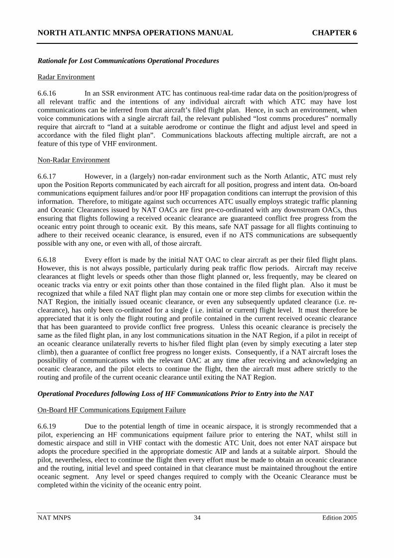
NORTH ATLANTIC MNPSA OPERATIONS MANUAL CHAPTER 6
NAT MNPS 34 Edition 2005
Rationale for Lost Communications Operational Procedures
Radar Environment
6.6.16 In an SSR environment ATC has continuous real-time radar data on the position/progress of all relevant traffic and the intentions of any individual aircraft with which ATC may have lost communications can be inferred from that aircraft’s filed flight plan. Hence, in such an environment, when voice communications with a single aircraft fail, the relevant published “lost comms procedures” normally require that aircraft to “land at a suitable aerodrome or continue the flight and adjust level and speed in accordance with the filed flight plan”. Communications blackouts affecting multiple aircraft, are not a feature of this type of VHF environment.
Non-Radar Environment
6.6.17 However, in a (largely) non-radar environment such as the North Atlantic, ATC must rely upon the Position Reports communicated by each aircraft for all position, progress and intent data. On-board communications equipment failures and/or poor HF propagation conditions can interrupt the provision of this information. Therefore, to mitigate against such occurrences ATC usually employs strategic traffic planning and Oceanic Clearances issued by NAT OACs are first pre-co-ordinated with any downstream OACs, thus ensuring that flights following a received oceanic clearance are guaranteed conflict free progress from the oceanic entry point through to oceanic exit. By this means, safe NAT passage for all flights continuing to adhere to their received oceanic clearance, is ensured, even if no ATS communications are subsequently possible with any one, or even with all, of those aircraft.
6.6.18 Every effort is made by the initial NAT OAC to clear aircraft as per their filed flight plans. However, this is not always possible, particularly during peak traffic flow periods. Aircraft may receive clearances at flight levels or speeds other than those flight planned or, less frequently, may be cleared on oceanic tracks via entry or exit points other than those contained in the filed flight plan. Also it must be recognized that while a filed NAT flight plan may contain one or more step climbs for execution within the NAT Region, the initially issued oceanic clearance, or even any subsequently updated clearance (i.e. re-clearance), has only been co-ordinated for a single ( i.e. initial or current) flight level. It must therefore be appreciated that it is only the flight routing and profile contained in the current received oceanic clearance that has been guaranteed to provide conflict free progress. Unless this oceanic clearance is precisely the same as the filed flight plan, in any lost communications situation in the NAT Region, if a pilot in receipt of an oceanic clearance unilaterally reverts to his/her filed flight plan (even by simply executing a later step climb), then a guarantee of conflict free progress no longer exists. Consequently, if a NAT aircraft loses the possibility of communications with the relevant OAC at any time after receiving and acknowledging an oceanic clearance, and the pilot elects to continue the flight, then the aircraft must adhere strictly to the routing and profile of the current oceanic clearance until exiting the NAT Region.
Operational Procedures following Loss of HF Communications Prior to Entry into the NAT
On-Board HF Communications Equipment Failure
6.6.19 Due to the potential length of time in oceanic airspace, it is strongly recommended that a pilot, experiencing an HF communications equipment failure prior to entering the NAT, whilst still in domestic airspace and still in VHF contact with the domestic ATC Unit, does not enter NAT airspace but adopts the procedure specified in the appropriate domestic AIP and lands at a suitable airport. Should the pilot, nevertheless, elect to continue the flight then every effort must be made to obtain an oceanic clearance and the routing, initial level and speed contained in that clearance must be maintained throughout the entire oceanic segment. Any level or speed changes required to comply with the Oceanic Clearance must be completed within the vicinity of the oceanic entry point.
NORTH ATLANTIC MNPSA OPERATIONS MANUAL CHAPTER 6
NAT MNPS 35 Edition 2005
6.6.20 If, however, an oceanic clearance cannot be obtained, the individual aircraft suffering radio communications equipment failure should enter oceanic airspace at the first oceanic entry point, level and speed contained in the filed flight plan and proceed via the filed flight plan route to landfall. The initial oceanic level and speed included in the filed flight plan must be maintained until landfall. N.B. This is the ONLY situation in which a pilot may unilaterally elect to “fly the flight plan” through the NAT Region.
“HF Blackout”
6.6.21 In the case of aircraft that lose ATC communications as a result of poor propagation conditions (“HF Blackouts”) when approaching NAT airspace through domestic airspace where ATC communications are also conducted via HF (e.g. entering the NAT through Northern Canadian airspace into the Reykjavik OCA), it is probably less advisable to execute unscheduled landings. These poor propagation conditions are very likely to affect many aircraft simultaneously and multiple diversions of “lost comms” aircraft might create further difficulties and risks.
6.6.22 As with the equipment failure situation, aircraft approaching the NAT and losing ATC communications as a result of poor HF radio propagation conditions, should if already in receipt of an oceanic clearance, follow the routing specified in that clearance and maintain the initial cleared level and speed throughout the oceanic segment i.e. through to landfall.
6.6.23 However, in these HF Blackout circumstances, if no oceanic clearance has been received, the aircraft must remain at the last cleared domestic flight level, not only to the ocean entry point but also throughout the whole subsequent oceanic segment (i.e. until final landfall). This is in stark contrast to the equipment failure case. In such HF Blackouts, pilots must not effect level changes to comply with filed flight plans. Such aircraft should, however, enter oceanic airspace at the first oceanic entry point and speed contained in the filed flight plan and proceed via the filed flight plan route to landfall.
6.6.24 The rationale here must be appreciated. In such circumstances it is likely that ATC will have simultaneously lost HF communications with multiple aircraft in the same vicinity. Should pilots then wrongly apply the “normal” radio failure procedures and “fly the flight plan”, there is a possibility that two such aircraft may have filed conflicting flight paths/levels through the subsequent oceanic airspace, and without communications with either aircraft, ATC would then be unable to intervene to resolve the conflict. Since safe aircraft level separation assurance has already been incorporated into the current domestic clearances, it is consequently imperative that under such (Domestic and Oceanic) HF-blackout circumstances, all aircraft electing to continue flight into NAT oceanic airspace without a received and acknowledged oceanic clearance, should adhere to the flight level in the last received domestic clearance. No level changes should be made to comply with a filed oceanic level that is different from that of the domestic clearance in effect at the time that ATC air-ground communications were lost.
Operational Procedures following Loss of HF Communications after Entering the NAT
6.6.25 If the HF communications equipment failure occurs or HF Blackout conditions are encountered after entering the NAT then : -
The pilot must proceed in accordance with the last received and acknowledged Oceanic Clearance, including level and speed, to the last specified oceanic route point (normally landfall). After passing this point, the pilot should conform with the relevant AIP specified State procedures/regulations and if necessary rejoin the filed flight plan route by proceeding, via the published ATS route structure where possible, to the next significant point contained in the filed flight plan. Note: the relevant State procedures/regulations to be followed by an aircraft in order to rejoin its filed Flight Plan route are specified in detail in the appropriate State AIP.
NORTH ATLANTIC MNPSA OPERATIONS MANUAL CHAPTER 6
NAT MNPS 36 Edition 2005
6.6.26 Aircraft with a destination within the NAT Region should proceed to their clearance limit and follow the ICAO standard procedure to commence descent from the appropriate designated navigation aid serving the destination aerodrome at, or as close as possible to, the expected approach time. Detailed procedures are promulgated in relevant State AIPs.
Summary of Operational Procedures Required following Loss of Air/Ground ATS Communications in the NAT Region
• Equipment Failure before receiving an Oceanic Clearance:-
Divert or fly the Flight Plan route, speed and initial planned oceanic level to landfall.
• Blackout encountered (in an HF comms Domestic ATC environment) before receiving an Oceanic Clearance:-
Continue at Domestic cleared level and follow flight planned route and speed to landfall.
• Equipment Failure or Blackout after receiving an Oceanic Clearance:-
Fly that clearance to landfall.
In all cases, after landfall rejoin, or continue on, the flight planned route, using appropriate State AIP specified procedures for the domestic airspace entered.
6.7 OPERATION OF TRANSPONDERS
6.7.1 Unless otherwise directed by ATC, pilots of aircraft equipped with SSR transponders flying in the NAT FIRs will operate transponders continuously in Mode A/C Code 2000, except that the last assigned code will be retained for a period of 30 min after entry into NAT airspace. Pilots should note that it is important to change from the last assigned domestic code to the Mode A/C Code 2000 since the original domestic code may not be recognised by the subsequent Domestic Radar Service on exit from the oceanic airspace. It should be noted that this procedure does not affect the use of the special purpose codes (7500, 7600 and 7700) in cases of: unlawful interference, radio failure or emergency. However, given the current heightened security environment crews must exercise CAUTION when selecting Codes not to inadvertently cycling through any of these special purpose codes and thereby possibly initiate the launching of an interception.
6.7.2 Reykjavik ACC provides a radar control service in the south-eastern part of its area and consequently transponder codes issued by Reykjavik ACC must be retained throughout the Reykjavik OCA until advised by ATC.
6.8 AIRBORNE COLLISION AVOIDANCE SYSTEMS (ACAS)
6.8.1 From 1 January 2005, all turbine-engined aeroplanes having a maximum certificated take-off mass exceeding 5,700 kg or authorized to carry more than 19 passengers are required to carry and operate ACAS II in the NAT Region. Pilots should report all ACAS Resolution Advisories which occur in the NAT Region to the controlling authority for the airspace involved. (See further on this in Chapter 11.)
NORTH ATLANTIC MNPSA OPERATIONS MANUAL CHAPTER 7
NAT MNPS 37 Edition 2005
Chapter 7: Application of Mach Number Technique
7.1 DESCRIPTION OF TERMS
7.1.1 The term ‘Mach Number Technique’ is used to describe a technique whereby subsonic turbojet aircraft operating successively along suitable routes are cleared by ATC to maintain appropriate Mach Numbers for a relevant portion of the en route phase of their flight.
7.2 OBJECTIVE
7.2.1 The principal objective of the use of Mach Number Technique is to achieve improved utilisation of the airspace on long route segments where ATC has no means, other than position reports, of ensuring that the longitudinal separation between successive aircraft is not reduced below the established minimum. Practical experience has shown that when two or more turbojet aircraft, operating along the same route at the same flight level, maintain the same Mach Number, they are more likely to maintain a constant time interval between each other than when using other methods. This is due to the fact that the aircraft concerned are normally subject to approximately the same wind and air temperature conditions, and minor variations in speed, which might increase and decrease the spacing between them, tend to be neutralised over long periods of flight.
7.2.2 For many aircraft types the cockpit instrument displays the True Mach being flown. However, for some types the AFM notes a correction that must be made to the Indicated Mach to provide the True Mach. It is important to recognise that the maintenance of longitudinal separations depends upon the assumption that the ATC assigned Mach numbers maintained by all aircraft are True Mach numbers. Pilots must therefore ensure that any required corrections to indicated Mach are taken into account when complying with the True Mach number specified in the ATC clearance.
7.3 PROCEDURES IN NAT OCEANIC AIRSPACE
7.3.1 The ATC clearance includes the assigned (True) Mach Number which is to be maintained. It is therefore necessary that information on the desired Mach Number be included in the flight plan for turbojet aircraft intending to fly in NAT oceanic airspace. ATC uses Mach Number together with pilot position reports to calculate estimated times for significant points along track. These times provide the basis for longitudinal separation between aircraft and for co-ordination with adjacent ATC units.
7.3.2 ATC will try to accommodate pilot/dispatcher requested or flight planned Mach Numbers when issuing Oceanic Clearances. It is rare that ATC will assign a Mach Number more than 0.01 faster or 0.02 slower than that requested. The prescribed longitudinal separation between successive aircraft flying a particular track at the same flight level is established over the oceanic entry point. Successive aircraft following the same track may be assigned different Mach Numbers but these will be such as to ensure that prescribed minimum separations are assured throughout the oceanic crossing. Intervention by ATC thereafter should normally only be necessary if an aircraft is required to change its Mach Number due to conflicting traffic or to change its flight level.
7.3.3 It is, however, important to recognise that the establishment and subsequent monitoring of longitudinal separation is totally reliant upon aircraft providing accurate waypoint passing times in position reports. It is therefore essential that pilots conducting flights in MNPS Airspace utilise accurate clocks and synchronise these with a standard time signal, based on UTC, prior to entering MNPS Airspace. It should be noted that some aircraft clocks can only be re-set while the aircraft is on the ground. (See further comments on time-keeping/longitudinal navigation in Chapter 1 and Chapter 8.)
NORTH ATLANTIC MNPSA OPERATIONS MANUAL CHAPTER 7
NAT MNPS 38 Edition 2005
7.3.4 In the application of Mach Number Technique, pilots must adhere strictly to their assigned True Mach Numbers unless a specific re-clearance is obtained from the appropriate ATC unit. However, as the aircraft weight reduces it may be more fuel efficient to adjust the Mach Number. Since the in-trail and crossing track separations between individual aircraft are established on the basis of ETAs passed to, or calculated by, ATC, it is essential that ATC approval is requested prior to effecting any change in cruise Mach Number. Such approval will be given if traffic conditions permit. If an immediate temporary change in the Mach Number is essential, e.g. due to turbulence, ATC must be notified as soon as possible.
7.3.5 Pilots should maintain their last assigned Mach Number during step-climbs in oceanic airspace. If due to aircraft performance this is not feasible ATC should be advised at the time of the request for the step climb.
7.4 PROCEDURE AFTER LEAVING OCEANIC AIRSPACE
7.4.1 After leaving oceanic airspace pilots must maintain their assigned Mach Number in domestic controlled airspace unless and until the appropriate ATC unit authorises a change.
NORTH ATLANTIC MNPSA OPERATIONS MANUAL CHAPTER 8
NAT MNPS 39 Edition 2005
Chapter 8: MNPS Flight Operation & Navigation Procedures
8.1 INTRODUCTION
8.1.1 The aircraft navigation systems necessary for flying in NAT MNPS Airspace are capable of high-performance standards. However it is essential that stringent cross-checking procedures are employed, both to ensure that these systems perform to their full capabilities and to minimise the consequences of equipment failures and possible human errors.
8.1.2 Navigation systems are continuously evolving and early editions of this Manual concentrated on offering specific guidance on the use of individual systems. Rather than specifying the types of equipment required for flying in defined airspace, current thinking is moving towards specifying a Required Navigation Performance (RNP), in other words a track keeping capability. As an example, the navigation performance accuracy of the aircraft population operating in airspace designated RNP X airspace would be expected to be X nm on a 95% containment basis. The NAT Minimum Navigation Performance Specification (MNPS) inter alia defines a requirement for the standard deviation of lateral track errors to be less than 6.3 nms. Since two standard deviations provide for about 95 % containment, the MNPS statement is effectively equivalent to an RNP value of 12.6. It is also perhaps interesting to note that actual measurements of the achieved navigation performance by the entire fleet of NAT aircraft, even before GPS came into use by a large proportion, indicated an achieved standard deviation of approximately 2 nms.
8.1.3 MNPS was devised and implemented in the NAT Region long before the RNP concept was developed. MNPS was established primarily with the NAT OTS environment in mind. The defining waypoints of OTS tracks are specified by whole degrees of latitude and, using an effective 60 nms lateral separation standard, most adjacent tracks are separated by only one degree of latitude at each ten-degree meridian. The traffic density in the OTS is higher than in any other oceanic airspace. In such a densely populated flexible track system (one that changes twice every day), it is essential to avoid (whole degree) waypoint insertion errors by crews. Such errors in the NAT MNPSA will inevitably result in a conflict with traffic on an adjacent track. For this reason Minimum Navigation Performance Specifications had to include not just the technical navigation accuracy of the Long-range Navigation Systems used on the aircraft but also the crew navigation procedures employed. The MNPS statement thus involves both cockpit/flight deck procedures and crew training requirements. In the early days of the RNP concept, it was these additional requirements that separated MNPS from RNP. However, RNP has come a long way since its inception and the development of the RNP-10 approvals for PAC operations have brought it much closer to the original MNPS concept. The ICAO Air Navigation Plan for the North Atlantic Region states that the intention in the future is that navigational performance is expected to be tied to a level of RNP.
(For more detailed information on RNP and MNPS see the following ICAO Documents: Doc 9613 – ‘Manual on Required Navigation Performance’ and NAT Doc 001 – ‘Consolidated Guidance and Information Material concerning Air Navigation in the North Atlantic Region’(available at http://www.nat-pco.org /.)
8.1.4 Obviously, there are several combinations of airborne sensors, receivers, computers with navigation data bases and displays which are capable of producing like accuracies, and which with inputs to automatic flight control systems provide track guidance. However, regardless of how sophisticated or mature a system is, it is still essential that stringent navigation and cross checking procedures are maintained if Gross Navigation Errors (GNEs) are to be avoided. A GNE within NAT Airspace is defined as a deviation from cleared track of 25 nm or more. Some of these errors are detected by means of long range radars as aircraft leave oceanic airspace. Other such errors may also be identified through the scrutiny of routine position reports from aircraft.
NORTH ATLANTIC MNPSA OPERATIONS MANUAL CHAPTER 8
NAT MNPS 40 Edition 2005
8.1.5 All reported navigation errors in North Atlantic airspace are thoroughly investigated. Records show that navigation equipment or system technical failures are now fortunately rare. However, when they do occur they can be subtle or progressive, resulting in a gradual and perhaps not immediately discernible degradation of performance. Chapter 11 of this Manual provides guidance on detection and recovery when such problems are encountered.
8.1.6 Unfortunately, human failings produce the vast majority of navigation errors in the North Atlantic Region. As indicated above, while the flexible OTS structure and the employment of a 60 nms lateral separation standard, provide for highly efficient use of NAT airspace, they also bring with them a demand for strictly disciplined navigation procedures. About half of NAT flights route via an OTS track and a large portion of the remaining random flights follow routes that at some point approach within one or two degrees of the outermost OTS tracks. One consequence of this is that a single digit error in the latitude of one significant point of an aircraft’s route definition will very likely lead to a conflict with another aircraft which is routing correctly via the resulting common significant point. Ironically, the risk of an actual collision between two aircraft routing via a common point, as is the case when such errors are made, is further exacerbated by the improved technical accuracy of the modern navigation equipment employed.
8.1.7 Today in North Atlantic operations the predominant source of aircraft positioning information is that of GPS. This includes aircraft that use stand-alone GPS equipment and aircraft where GPS positioning information is integrated into the system navigation solution (e.g. a GPS / IRS mix). The accuracy of GPS navigation is such that the actual flight paths of any two GPS equipped aircraft navigating to a common point will almost certainly pass that point within less than a wingspan of each other. Given that the North Atlantic is the most heavily used oceanic airspace anywhere in the world, it must therefore be appreciated that even a single digit error in just one waypoint, can result in a significant conflict potential.
8.1.8 The importance of employing strict navigation system operating procedures designed to avoid the insertion of wrong waypoints or misunderstandings between pilots and ATC over cleared routes, cannot be over-emphasised. The principles embodied in many of the procedures described in this Chapter are aimed squarely at the prevention of such problems.
8.1.9 Many of the procedures listed in this Chapter are not equipment specific and others may not be pertinent to every aircraft. For specific equipment, reference should be made to Manufacturers' and operators' handbooks and manuals.
8.1.10 There are various references in this material to two pilots; however when carried, a third crew member should be involved in all cross check procedures to the extent practicable.
8.1.11 Maintenance of a high standard of navigation performance is absolutely essential to the maintenance of safety in the NAT MNPS Airspace.
8.2 GENERAL PROCEDURES
Importance of Accurate Time
8.2.1 It must be recognised that proper operation of a correctly functioning LRNS will ensure that the aircraft follows its cleared track. ATC applies standard separations between cleared tracks and thereby assures the safe lateral separation of aircraft. However, longitudinal separations between subsequent aircraft following the same track and between aircraft on intersecting tracks are assessed in terms of differences in ETAs/ATAs at common waypoints. Aircraft clock errors resulting in position report time errors can therefore lead to an erosion of actual longitudinal separations between aircraft. It is thus vitally important that prior to entry into the NAT MNPS Airspace the time reference system to be used during the flight is accurately synchronised to UTC and that the calculation of waypoint ETAs and the reporting of waypoint ATAs are always referenced to this system. Many modern aircraft master clocks can only be
NORTH ATLANTIC MNPSA OPERATIONS MANUAL CHAPTER 8
NAT MNPS 41 Edition 2005
reset while the aircraft is on the ground. Thus the Pre-flight Procedures for any NAT MNPS flight must include a UTC time check and resynchronisation of the aircraft master clock. Lists of acceptable time sources for this purpose have been promulgated by NAT ATS Provider States.
8.2.2 The following are examples of acceptable time standards:
(1) GPS (Corrected to UTC) - Available at all times to those crews who can access time via approved on-board GPS (TSO-C129) equipment.
(2) WWV - National Institute of Standards (NIST - Fort Collins, Colorado). WWV operates continually H24 on 2500, 5000, 10,000, 15,000 and 20,000 kHz (AM/SSB) and provides UTC (voice) once every minute.
(3) CHU - National Research Council (NRC - Ottawa, Canada) - CHU operates continually H24 on 3330, 7335 and 14,670 kHz (SSB) and provides UTC (voice) once every minute (English even minutes, French odd minutes).
(4) BBC - British Broadcasting Corporation (United Kingdom). The BBC transmits on a number of domestic and world-wide frequencies and transmits the Greenwich time signal (referenced to UTC) once every hour on most frequencies, although there are some exceptions.
8.2.3 Further details of these and other acceptable time references can be found in AIS documentation of the NAT ATS Provider States. In general, the use of any other source of UTC, that can be shown to the State of the Operator or the State of Registry of the aircraft to be equivalent, may be allowed for this purpose.
The Use of a Master Document
8.2.4 Navigation procedures must include the establishment of some form of master working document to be used on the flight deck. This document may be based upon the flight plan, navigation log, or other suitable document which lists sequentially the waypoints defining the route, the track and distance between each waypoint, and other information relevant to navigation along the cleared track. When mentioned subsequently in this guidance material, this document will be referred to as the 'Master Document'.
8.2.5 Misuse of the Master Document can result in GNEs occurring and for this reason strict procedures regarding its use should be established. These procedures should include the following:
• only one Master Document to be used on the flight deck. However, this does not preclude other crew members maintaining a separate flight log.
• on INS equipped aircraft a waypoint numbering sequence should be established from the outset of the flight and entered on the Master Document. The identical numbering sequence should be used for storing waypoints in the navigation computers.
• for aircraft equipped with FMS data bases, FMS generated or inserted waypoints should be carefully compared to Master Document waypoints and cross checked by both pilots.
• an appropriate symbology should be adopted to indicate the status of each waypoint listed on the Master Document.
8.2.6 The following is a typical example of Master Document annotation. An individual operator’s procedures may differ slightly but the same principles should be applied:
NORTH ATLANTIC MNPSA OPERATIONS MANUAL CHAPTER 8
NAT MNPS 42 Edition 2005
• the waypoint number is entered against the relevant waypoint co-ordinates to indicate that the waypoint has been inserted into the navigation computers.
• the waypoint number is circled, to signify that insertion of the correct co-ordinates in the navigation computers has been double-checked independently by another crew member.
• the circled waypoint number is ticked, to signify that the relevant track and distance information has been double-checked.
• the circled waypoint number is crossed out, to signify that the aircraft has overflown the waypoint concerned.
8.2.7 All navigational information appearing on the Master Document must be checked against the best available prime source data. When a re-route is necessary, it is recommended that a new Master Document is prepared for the changed portion of the flight. If the original Master Document is to be used the old waypoints should be clearly crossed out and the new ones entered in their place.
8.2.8 When ATC clearances or re-clearances are being obtained, headsets should be worn. The inferior clarity of loud-speakers has, in the past, caused errors during receipt. Two qualified crew members should monitor such clearances, one of them recording the clearance on the Master Document as it is received, the other cross-checking the receipt and read-back. All waypoint co-ordinates should be read back in detail, adhering strictly to standard ICAO phraseology, except where approved local procedures make this unnecessary. Detailed procedures pertaining to abbreviated clearances/read-backs are contained in the appropriate AIPs, and in this Manual at Chapter 5 - Oceanic ATC Clearances.
Position Plotting
8.2.9 A simple plotting chart provides a visual presentation of the intended route which, otherwise, is defined only in terms of navigational co-ordinates. Plotting the intended route on such a chart may reveal errors and discrepancies in the navigational co-ordinates which can then be corrected immediately, before they reveal themselves in terms of a deviation from the ATC cleared route. As the flight progresses, plotting the aircraft's position on this chart will also serve the purpose of a navigation cross check, provided that the scale and graticule are suitable.
8.2.10 As the flight progresses in oceanic airspace, plotting the aircraft's position on this chart will help to confirm (when it falls precisely on track) that the flight is proceeding in accordance with its clearance. However, if the plotted position is laterally offset, the flight may be deviating unintentionally, and this possibility should be investigated at once.
8.2.11 It is recommended that a chart with an appropriate scale be used for plotting. Many company Progress Charts are of the wrong scale or too small. It has been noted that the use of plotting charts that are small can lead to oceanic errors. EAG Chart NAT (H/L) 1&1e; No 1 AIDU (MOD) Charts AT(H)1, 2, 3 & 4 and the Jeppesen North/Mid Atlantic Plotting Charts are all useful compromises between scale and overall chart size; while the NOAA/FAA North Atlantic Route Chart has the advantage, for plotting purposes, of a 1° latitude/longitude graticule."
Provision of Step-Climbs
8.2.12 Tactical radar control and tactical procedural control are exercised in some areas of the NAT MNPS Airspace. However, oceanic clearances for most NAT flights are of a strategic nature, whereby flights are allocated a conflict-free route and profile from coast-out to landfall. Although such strategic clearances normally specify a single flight level for the entire crossing, there is often scope for en route step-climb re-clearances as fuel burn-off makes higher levels more optimal. Controllers will accommodate
NORTH ATLANTIC MNPSA OPERATIONS MANUAL CHAPTER 8
NAT MNPS 43 Edition 2005
requests for step-climbs whenever possible. When so re-cleared, pilots should initiate the climb without delay (unless their discretion was invited) and always report to ATC immediately upon reaching the new cruising level.
Relief Crew Members
8.2.13 Very long range operations may include the use of relief crew. In such cases it is necessary to ensure that procedures are such that the continuity of the operation is not interrupted, particularly in respect of the handling and treatment of the navigational information.
8.3 PRE-FLIGHT PROCEDURES
Inertial Navigation Systems
Initial Insertion of Latitude and Longitude
8.3.1 Two fundamental principles concerning the operation of an IRS are: that it needs to be accurately aligned before flight; and that the actual position of the aircraft, at alignment, is set into the system. If either of these principles is violated, systematic errors will be introduced. These errors can be corrected whilst the aircraft is on the ground but it is not possible to adequately recover from them whilst the aircraft is in flight, despite indications to the contrary. Correct insertion of the initial position must therefore be checked before inertial systems are aligned and the position should be recorded in the flight log and/or Master Document. It is recommended that subsequent 'silent' checks of the present position and of the inertial velocity outputs (e.g. ground speed registering zero) be carried out independently by both pilots during (an early stage of) the pre-flight checks and again just before the aircraft is moved. Any discrepancies should be investigated.
8.3.2 With regard to the insertion of the initial co-ordinates whilst on the ramp, the following points should be taken into account:
• in some inertial systems, insertion errors exceeding about one degree of latitude will illuminate a malfunction light. It should be noted that very few systems provide protection against longitude insertion errors.
• at all times, but particularly in the vicinity of the Zero Degree E/W (Greenwich) Meridian or near to the Equator, care should be taken to ensure that the co-ordinates inserted are correct. (i.e. E/W or N/S).
System Alignment
8.3.3 The alignment of inertial systems must be completed and the equipment put into navigation mode prior to releasing the parking brake at the ramp. Some systems will align in about 10 minutes, others can take 15 minutes or more; expect alignment to take longer in extreme cold or at higher latitudes. A rapid realignment feature is sometimes provided but should only be used if, during an intermediate stop, it becomes necessary to increase the system accuracy. The aircraft must be stationary during rapid realignment which typically will take about one minute.
8.3.4 To ensure that there is adequate time for the initial alignment, the first crew member on the flight deck should normally put the inertial system(s) into the align mode as soon as practicable.
NORTH ATLANTIC MNPSA OPERATIONS MANUAL CHAPTER 8
NAT MNPS 44 Edition 2005
GNSS (GPS) Systems
8.3.5 As with conventional LRNS operation, GPS LRNS operation must be approved by the State of the Operator (or the State of Registry for International General Aviation operations) as part of the MNPS operational approval. When both the LRNSs required for unrestricted MNPS operations are GPSs the approval of their operation will include the requirement to carry out Pre-Departure Satellite Navigation Prediction Programmes (as shown below). When only one of the two LRNSs required is a GPS, State Authorities vary as to whether they require their operators to conduct such pre-departure programmes.
Satellite Availability
8.3.6 Given suitable geometry:
• Four satellites are required to determine 3-D position;
8.3.7 For Receiver Autonomous Integrity Monitoring (RAIM) purposes:
• Five satellites are required to detect the presence of a single faulty satellite;
8.3.8 For Fault Detection and Exclusion (FDE) purposes:
• Six satellites are required to identify a faulty satellite and exclude it from participating in further navigation solution calculations. (Note that an FDE algorithm is normally associated with a RAIM algorithm).
Note: the above numbers of satellites (for RAIM and FDE purposes only) may in each case be reduced by one if barometric aiding is used.
Satellite Navigation Prediction
8.3.9 When so required, operators intending to conduct GPS navigation in MNPS Airspace must utilise a Satellite Navigation Availability Prediction Programme specifically designated for the GPS equipment installed. This prediction programme must be capable of predicting, prior to departure for flight on a "specified route", the following:
• Any loss of navigation coverage (meaning that less than 3 satellites will be in view to the receiver).
and
• Any loss of the RAIM function and its duration.
Note: "specified route" is defined by a series of waypoints (to perhaps include the route to any required alternate), with the time between waypoints based on planned speeds. Since flight planned ground speeds and/or departure times may not be met, the pre-departure prediction must be performed for a range of expected ground speeds.
8.3.10 This prediction programme must use appropriate parameters from the RAIM algorithm employed by the installed GPS equipment. In order to perform the predictions this programme must provide the capability for the operator to manually designate satellites that are scheduled to be unavailable. Such information is not included in the GPS almanac or ephemeris data in the navigation message (i.e. the GPS receiver does not receive this information). Information on GPS satellite outages is promulgated via the U.S. NOTAM Office. The KNMH transmitting station (US Coast Guard Station, Washington D.C.) is
NORTH ATLANTIC MNPSA OPERATIONS MANUAL CHAPTER 8
NAT MNPS 45 Edition 2005
responsible for release (in NOTAM format) of information relating to the operating condition of the GPS constellation satellites. These NOTAMs can be obtained through direct query to the USA data bank, via the AFTN, using the following service message format : SVC RQ INT LOC = KNMH addressed to KDZZNAXX. Such information can also be found on the US Coastguard Web site at http://www.navcen.uscg.gov ."
8.3.11 When GPS is being used as a supplementary navigation means or when GPS is only one of the two LRNSs required for MNPS approval (e.g. when the second LRNS is an IRS/INS installation) then some States of Registry may not require the operator to conduct pre-flight RAIM checks.
Operational Control Restrictions
The Capability to determine a GPS position
8.3.12 Prior to departure, the operator must use the prediction programme to first demonstrate that forecast satellite outages will not result in a loss of navigation coverage (i.e. the capability to determine position) on any part of the specified route of flight. If such outages are detected by the programme, the flight will need to be re-routed, delayed or cancelled.
Determination of the Availability of RAIM
8.3.13 Once the position determination function is assured (i.e. no loss in navigation coverage for the route has been predicted), the operator must run the RAIM outage prediction programme. Any continuous outage of RAIM capability of greater than 51 minutes in MNPS airspace means again that the flight should be re-routed, delayed or cancelled. It is understood that some prediction programmes carry out both these checks together.
Note - Derivation of the 51 minute limit – At the instant the RAIM capability is lost, it is assumed that the GPS navigation solution proceeds to direct the aircraft away from track at a speed of 35 knots. With the current MNPS track spacing of 60 nautical miles, it is further assumed that aircraft on adjacent tracks have a lateral “safety buffer” of 30 nautical miles. At 35 knots it will take an aircraft 51 minutes to exit this “safety buffer”. It should be noted that this is a very conservative methodology and it is thought unlikely that a RAIM outage alone could cause such errant navigation behaviour.
Loading of Initial Waypoints
8.3.14 The manual entry of waypoint data into the navigation systems must be a co-ordinated operation by two persons, working in sequence and independently: one should key in and insert the data, and subsequently the other should recall it and confirm it against source information. It is not sufficient for one crew member just to observe or assist another crew member inserting the data.
8.3.15 The ramp position of the aircraft, plus at least two additional waypoints, or, if the onboard equipment allows, all the waypoints relevant to the flight, should be loaded while the aircraft is at the ramp. However, it is more important initially to ensure that the first en route waypoint is inserted accurately.
Note - The vast majority of commercial air transport aircraft operating in MNPS airspace have an IRS/INS as part of their Long Range navigation fit. An increasing number of those with IRS/INS also have GPS and whilst GPS may then be considered the primary LRNS, these aircraft are still required to input the ramp position. This should then be compared with the GPS solution. For those few aircraft with GPS as the only LRNS, whilst there may be no need to actually load the ramp position, it is good airmanship and recommended operational practice to compare the published ramp position with the GPS-derived position. Without selective availability GPS should give a position
NORTH ATLANTIC MNPSA OPERATIONS MANUAL CHAPTER 8
NAT MNPS 46 Edition 2005
within 30 metres of the published ramp position. If the GPS position is more than 100 metres from the published ground position, then the cause should be investigated. If sufficient satellites are in view the most likely causes are GPS receiver error, atmospheric interference, or, incorrect ramp co-ordinates.
8.3.16 During flight, at least two current waypoints beyond the leg being navigated should be maintained in the Control Display Units (CDUs) until the destination ramp co-ordinates are loaded. Two pilots should be responsible for loading, recalling and checking the accuracy of the inserted waypoints; one loading and the other subsequently recalling and checking them independently. However, this process should not be permitted to engage the attention of both pilots simultaneously during the flight. Where remote loading of the units is possible, this permits one pilot to cross-check that the data inserted automatically is indeed accurate.
8.3.17 An alternative and acceptable procedure is for the two pilots silently and independently to load their own initial waypoints and then cross-check them. The pilot responsible for carrying out the verification should work from the CDU display to the Master Document rather than in the opposite direction. This may lessen the risk of the pilot 'seeing what is expected to be seen’ rather than what is actually displayed.
Flight Plan Check
8.3.18 The purpose of this check is to ensure complete compatibility between the data in the Master Document and the calculated output from the navigation systems. Typical actions could include:
• checking the distance from the ramp position to the first waypoint. Some systems will account for the track distance involved in an ATC SID; in others, an appropriate allowance for a SID may have to be made to the great circle distance indicated in order to match that in the Master Document. If there is significant disagreement, rechecking initial position and waypoint co-ordinates may be necessary.
• selecting track waypoint 1 to waypoint 2 and doing the following:
- checking accuracy of the indicated distance against that in the Master Document;
- checking, when data available, that the track displayed is as listed in the Master Document. (This check will show up any errors made in lat/long designators (i.e. N/S or E/W).)
• similar checks should be carried out for subsequent pairs of waypoints and any discrepancies between the Master Document and displayed data checked for possible waypoint insertion errors. These checks can be co-ordinated between the two pilots checking against the information in the Master Document.
• when each leg of the flight has been checked in this manner it should be annotated on the Master Document by means of a suitable symbology as previously suggested (See "The Use of a Master Document” above).
• some systems have integral navigation databases and it is essential that the recency of the database being used is known. It must be recognised that even the co-ordinates of waypoint positions contained in a data base have been keyed in at some point by another human. The possibility of input errors is always present. Do not assume the infallibility of navigation databases and always maintain the same thorough principles which are applied in the checking of your own manual inputs.
NORTH ATLANTIC MNPSA OPERATIONS MANUAL CHAPTER 8
NAT MNPS 47 Edition 2005
Leaving the Ramp
8.3.19 The aircraft must not be moved prior to the navigation mode being initiated, otherwise inertial navigation systems must be realigned. Prior to leaving the ramp Zero Ground Speed indications from the LRNS should be confirmed. Any excessive Ground Speeds noted while on chocks should be resolved by checking fault codes, the currency of data bases and RAIM (if GPS is employed).
8.3.20 After leaving the ramp, inertial groundspeeds should be checked (a significantly erroneous reading may indicate a faulty or less reliable inertial unit). A check should be made on any malfunction codes whilst the aircraft is stopped but after it has taxied at least part of the way to the take-off position; any significant ground-speed indications whilst stationary may indicate a faulty inertial unit such as a tilted platform. Prior to take-off, operators with an avionic fit which employs an electronic map display should confirm that the derived position indicates that the aircraft is at the start of the runway.
8.3.21 Many modern aircraft are equipped with FMS navigation systems (i.e. Flight Management Computers fed by multiple navigation sensors.). Once the FMS is put into 'Nav' mode, the system decides on the most appropriate (i.e. accurate) navigation sensors to use for position determination. If GPS is part of the solution, then the position is normally predominantly based on GPS inputs with the IRS/INS in a supporting role. It may therefore be difficult to know exactly what component of the navigation solution (IRS, GPS, DME etc) is being used to derive position at any one time. With an FMS-based system, or a GPS stand-alone system, the “Leaving the Ramp” checks should designed to provide assurance that the navigation information presented is indeed 'sensible'.
8.4 IN FLIGHT PROCEDURES
Initial flight
8.4.1 It is recommended that during the initial part of the flight, ground navaids should be used to verify the performance of the LRNSs. Large or unusual ‘map shifts’ in FMS output, or other discrepancies in navigation data, could be due to inertial platform misalignment or initialisation errors. Position updates to the FMS will not correct these errors despite possible indications to the contrary. If such a situation is encountered when INS/IRS are the primary LRNSs then it would be unwise to continue into NAT MNPS Airspace. Pilots should consider landing in order to investigate the cause and then perhaps be in a position to correct the problem.
ATC Oceanic Clearance
8.4.2 Where practicable, two flight crew members should listen to and record every ATC clearance and both agree that the recording is correct. Any doubt should be resolved by requesting clarification from ATC.
8.4.3 If the ATC oceanic cleared route is identical to the flight planned track, it should be drawn on the plotting chart and verified by the other pilot.
8.4.4 If the aircraft is cleared by ATC on a different track from that flight planned, it is strongly recommended that a new Master Document be prepared showing the details of the cleared track. Overwriting of the existing flight plan can cause difficulties in reading the waypoint numbers and the new co-ordinates. For this purpose, a blank pro-forma Master Document (flight plan) should be carried with the flight documents. One flight crew member should transcribe track and distance data from the appropriate reference source onto the new Master Document pro-forma and this should be checked by another crew member. If necessary, a new plotting chart may be used on which to draw the new track. The new document(s) should be used for the oceanic crossing. If the subsequent domestic portion of the flight
NORTH ATLANTIC MNPSA OPERATIONS MANUAL CHAPTER 8
NAT MNPS 48 Edition 2005
corresponds to that contained in the original flight plan, it should be possible to revert to the original Master Document at the appropriate point.
8.4.5 Experience suggests that when ATC issues a re-clearance involving re-routing and new waypoints, there is a consequential increase in the risk of errors being made. Therefore, this situation should be treated virtually as the start of a new flight; and the procedures employed with respect to the following, should all be identical to those procedures employed at the beginning of a flight:
• copying the ATC re-clearance;
• amending the Master Document;
• loading and checking waypoints;
• extracting and verifying flight plan information, tracks and distances, etc.; and
• preparing a new plotting chart.
8.4.6 Strict adherence to the above procedures should minimise the risk of error. However, flight deck management should be such that one pilot is designated to be responsible for flying the aircraft whilst the other pilot carries out any required amendments to documentation and reprogramming of the navigation systems - appropriately monitored by the pilot flying the aircraft, as and when necessary.
Approaching the Ocean
8.4.7 Prior to entering MNPS Airspace, the accuracy of the LRNSs should be thoroughly checked, if necessary by using independent navigation aids. For example, INS position can be checked by reference to en route or proximate VOR/DMEs, etc. However, with a modern FMS, the system decides which LRNS is to be used, and indeed, the FMS may be taking information from DMEs (and possibly VORs) as well as the LRNS carried. Nevertheless, in spite of all this modern technology and even if the FMS is using GPS, it is still worthwhile to carry out a 'reasonableness' check of the FMS/GPS position, using (for example) DME/VOR distance and bearing.
8.4.8 When appropriate and possible, the navigation system which, in the opinion of the pilot, has performed most accurately since departure should be selected for automatic navigation steering.
8.4.9 In view of the importance of following the correct track in oceanic airspace, it is advisable at this stage of flight that, if carried, a third pilot or equivalent crew member should check the clearance waypoints which have been inserted into the navigation system, using source information such as the track message or data link clearance if applicable.
Entering the MNPS Airspace and Reaching an Oceanic Waypoint
8.4.10 When passing waypoints, the following checks should be carried out:
• just prior to the waypoint, check the present position co-ordinates of each navigation system against the cleared route in the Master Document, and
• check the next two waypoints in each navigation system against the Master Document.
• at the waypoint, check the distance to the next waypoint, confirm that the aircraft turns in the correct direction and takes up a new heading and track appropriate to the leg to the next waypoint.
NORTH ATLANTIC MNPSA OPERATIONS MANUAL CHAPTER 8
NAT MNPS 49 Edition 2005
• before transmitting the position report to ATC, verify the waypoint co-ordinates against the Master Document and those in the steering navigation system. When feasible the position report “next” and “next plus 1” waypoint co-ordinates should be read from the CDU of the navigation system coupled to the autopilot.
8.4.11 Even if automatic waypoint position reporting via data link (e.g. ADS, CPDLC or FMC WPR) is being used to provide position reports to ATC the above checks should still be performed.
8.4.12 The crew should be prepared for possible ATC follow-up to the position report.
Routine Monitoring
8.4.13 It is important to remember that there are a number of ways in which the autopilot may unobtrusively become disconnected from the steering mode. Therefore, regular checks of correct engagement with the navigation system should be made.
8.4.14 It is recommended that where possible the navigation system coupled to the autopilot should display the present position co-ordinates throughout the flight. If these are then plotted as suggested above, they will provide confirmation that the aircraft is tracking in accordance with its ATC clearance. Distance to go information should be available on the instrument panel, whilst a waypoint alert light, where fitted, provides a reminder of the aircraft’s imminent arrival over the next waypoint.
8.4.15 A position check should be made at each waypoint and the present position plotted 10 minutes after passing each waypoint. For a generally east-west flight, it may be simpler to plot present position a further 2 degrees of longitude after each 10 Degree waypoint. There may be circumstances, (e.g. when, due to equipment failure, only one LRNS remains serviceable) in which additional plots midway between each waypoint may be justified.
8.4.16 The navigation system not being used to steer the aircraft should display cross-track distance and track angle error. Both of these should be monitored, with cross-track distance being displayed on the HSI where feasible.
Approaching Landfall
8.4.17 When the aircraft is within range of land based navaids, and the crew is confident that these navaids are providing reliable navigation information, consideration should be given to updating the LRNSs. Automatic updating of the LRNSs from other navaids should be closely monitored, and before entry into airspace where different navigation requirements have been specified (e.g. RNP5 in European BRNAV airspace), crews should use all aids (including VORs and DMEs) to confirm that the in-use navigation system is operating to the required accuracy. If there is any doubt regarding system accuracy, the appropriate ATC unit should be informed.
8.5 SPECIAL IN-FLIGHT PROCEDURES
Strategic Lateral Offset Procedure (SLOP)
8.5.1 ATC clearances are designed to ensure that separation standards are continually maintained for all traffic. However, the chain of clearance definition, delivery and execution involves a series of technical system processes and human actions. Errors are very rare but they do occur. Neither pilots nor controllers are infallible. Gross Navigation Errors (usually involving whole latitude degree mistakes in route waypoints) are made, and aircraft are sometimes flown at flight levels other than those expected by the controller. As previously indicated, when such errors are made, ironically, the extreme accuracies of modern navigation and height keeping systems themselves exacerbate the risk of an actual collision. Within an SSR

NORTH ATLANTIC MNPSA OPERATIONS MANUAL CHAPTER 8
NAT MNPS 50 Edition 2005
environment the controller is alerted to such errors and can therefore intervene in a timely fashion. In Oceanic airspace, such as the North Atlantic, in which the controller’s awareness of traffic disposition is reliant largely upon pilot voice position reports, this is not the case. Consequently, it has been determined that allowing aircraft conducting oceanic flight to fly lateral offsets will provide an additional safety margin and mitigate the risk of traffic conflict when non-normal events such as aircraft navigation errors, height deviation errors and turbulence induced altitude-keeping errors do occur. Collision risk is significantly reduced by application of these offsets. This procedure is known as “Strategic Lateral Offset Procedure (SLOP)”.
8.5.2 This procedure provides for offsets within the following guidelines:
• along a route or track there will be three positions that an aircraft may fly: centreline or one or two miles right; and
• offsets will not exceed 2 NM right of centreline.
8.5.3 Distributing aircraft laterally and equally across the three available positions adds an additional safety margin and reduces collision risk. This is now a standard operating procedure for the entire NAT Region and pilots are required to adopt this procedure as is appropriate. In this connection, it should be noted that:
• Aircraft without automatic offset programming capability must fly the centreline.
• Operators capable of programming automatic offsets may fly the centreline or offset one or two nautical miles right of centreline to obtain lateral spacing from nearby aircraft. (Offsets will not exceed 2 NM right of centreline and offsets left of track centreline must not be made). An aircraft overtaking another aircraft should offset within the confines of this procedure, if capable, so as to create the least amount of wake turbulence for the aircraft being overtaken.
• Pilots should use whatever means are available (e.g. TCAS, communications, visual acquisition, GPWS) to determine the best flight path to fly.
• For wake turbulence purposes, pilots should also fly one of the three positions shown above. Pilots should not offset to the left of centreline nor offset more than 2 nm right of centreline. Pilots may contact other aircraft on the air-to-air channel, 123.45 MHz, as necessary; to co-ordinate the best wake turbulence mutual offset option. (Note. It is recognised that the pilot will use his/her judgement to determine the action most appropriate to any given situation and that the pilot has the final authority and responsibility for the safe operations of the aeroplane. See also Chapter 11, paragraph 11.5.) As indicated below, contact with ATC is not required.
• Pilots may apply an offset outbound at the oceanic entry point and must return to centreline prior to the oceanic exit point.
• Aircraft transiting radar-controlled airspace mid-ocean should remain on their already established offset positions.
• There is no ATC clearance required for this procedure and it is not necessary that ATC be advised.
• Voice Position reports should be based on the waypoints of the current ATC clearance and not the offset positions.
NORTH ATLANTIC MNPSA OPERATIONS MANUAL CHAPTER 8
NAT MNPS 51 Edition 2005
Monitoring during Distractions from Routine
8.5.4 Training and drills should ensure that minor emergencies or interruptions to normal routine are not allowed to distract the crew to the extent that the navigation system is mishandled.
8.5.5 If during flight the autopilot is disconnected (e.g. because of turbulence), care must be taken when the navigation steering is re-engaged to ensure that the correct procedure is followed. If the system in use sets specific limits on automatic capture, the across-track indications should be monitored to ensure proper recapture of the programmed flight path/profile.
8.5.6 Where crews have set low angles of bank, perhaps 10° or less, say for passenger comfort considerations, it is essential to be particularly alert to possible imperceptible departures from cleared track.
Avoiding Confusion between Magnetic and True Track Reference
8.5.7 To cover all navigation requirements, some operators produce flight plans giving both magnetic and true tracks. However, especially if crews are changing to a new system, there is a risk that at some stage (e.g. during partial system failure, re-clearances, etc.), confusion may arise in selecting the correct values. Operators should therefore devise procedures which will reduce this risk, as well as ensuring that the subject is covered during training.
8.5.8 Crews who decide to check or update their LRNSs by reference to VORs should remember that in the Canadian Northern Domestic Airspace these may be oriented with reference to true north, rather than magnetic north.
Navigation in the Area of Compass Unreliability
8.5.9 In areas of compass unreliability basic inertial navigation requires no special procedures but most operators feel it is desirable to retain an independent heading reference in case of system failure.
8.5.10 Different manufacturers may offer their own solutions to the special problems existing in areas of compass unreliability. Such solutions should not however involve the use of charts and manual measurement of direction.
8.5.11 Furthermore, Operators/Pilots are reminded that before operating in an Area of Magnetic Unreliability they are responsible for checking with their State Authorities whether specific regulatory approval is required.
Deliberate Deviation from Track
8.5.12 Deliberate temporary deviations from track are sometimes necessary, usually to avoid severe weather; whenever possible, prior ATC approval should be obtained. Such deviations have often been the source of gross errors as a consequence of failing to re-engage the autopilot with the navigation system. It should also be noted that selection of the 'turbulence' mode of the autopilot on some aircraft may have the effect of disengaging it from the aircraft navigation system. After use of the turbulence mode, extra care should be taken to ensure that the desired track is recaptured by the steering navigation system.
NORTH ATLANTIC MNPSA OPERATIONS MANUAL CHAPTER 8
NAT MNPS 52 Edition 2005
8.6 POST-FLIGHT PROCEDURES
Inertial Navigation System Accuracy Check
8.6.1 At the end of each flight, an evaluation of accuracy of the aircraft's navigation systems should be carried out. Equipment operating manuals specify maxima for radial errors before a system is considered to be unserviceable. For inertial systems these are in the order of 2 nms per hour. One method used to determine radial error is to input the shutdown ramp position; in other systems error messages are output giving differences between raw inertial reference positions and computed radio navigation updated positions. Whatever method is used, a record should be kept of the performance of each INS.
8.7 HORIZONTAL NAVIGATION PERFORMANCE MONITORING
8.7.1 The navigation performance of operators within NAT MNPS Airspace is monitored on a continual basis. The navigation accuracy achieved by NAT MNPS aircraft is periodically measured and additionally all identified instances of significant deviation from cleared track are subject to thorough investigation by the NAT Central Monitoring Agency (CMA), currently operated on behalf of the NAT SPG by the UK National Air Traffic Services Limited.
8.7.2 When a GNE is identified, follow-up action after flight is taken, both with the operator and the State of Registry of the aircraft involved, to establish the reason/cause and to confirm the approval of the flight to operate in NAT MNPS Airspace. The format of the (navigation) Error Investigation Form used for follow-up action is as shown at Attachment 1. Operational errors can have a significant effect on the assessment of risk in the system. For their safety and the safety of other users, crews are reminded of the importance of co-operating with the reporting OAC in the provision of incident information.
8.7.3 The overall navigation performance of all aircraft in the MNPS Airspace is continually assessed and compared to the standards established for the Region, to ensure that the TLS is being maintained
NORTH ATLANTIC MNPSA OPERATIONS MANUAL CHAPTER 9
NAT MNPS 53 Edition 2005
Chapter 9: RVSM Flight in MNPS Airspace
9.1 GENERAL
9.1.1 The aircraft altimetry and height keeping systems necessary for flying in RVSM airspace are capable of high-performance standards. However it is essential that stringent operating procedures are employed, both to ensure that these systems perform to their full capabilities and also to minimise the consequences of equipment failures and possible human errors.
9.1.2 As is the case with lateral navigation systems, technical failures of altimetry and/or height keeping systems are extremely rare within the NAT MNPSA. However, less rare in the NAT MNPSA are situations in which an aircraft is flown at a level other that cleared by ATC. ATC Loop Errors, when there is a misunderstanding or miscommunication between ATC and the pilot over the actual cleared level, unfortunately do occur. In an SSR environment ATC are alerted to any such error immediately the aircraft departs from the cleared level. Furthermore with Direct Controller Pilot Communications (DCPC) the controller can instantly intervene to resolve the situation and/or to provide potential conflict warnings to other traffic. In the NAT MNPSA SSR coverage is very limited and regular air/ground ATC communications are conducted via a third party radio operator, most commonly using HF.
9.1.3 Severe turbulence in the NAT MNPSA is uncommon but mountain waves in the vicinity of Greenland and clear air turbulence associated with jet streams are not unknown. Aircraft encountering such conditions can inadvertently depart from their cleared levels or the pilot may elect to change level to avoid the effects of the turbulence. Other circumstances also occur in which the pilot will be forced to change level, before an appropriate ATC re-clearance can be obtained, e.g. power or pressurisation failure, freezing fuel, etc. Again, without surveillance or DCPC, there can be a significant lag between the aircraft’s departure from its cleared level and any possible action from the controller to provide separation from any other potentially conflicting traffic.
9.1.4 It must be appreciated that the NAT MNPSA is the busiest oceanic airspace in the world. Furthermore, NAT traffic is comprised of a very wide range of aircraft types, flying a wide range of sector lengths and carrying a significant range of loads. As a result, optimum flight levels vary over the whole jet cruising range and nearly all the flight levels of the core tracks of the OTS, during peak hours, are fully occupied. Also, the Mach Numbers flown can vary significantly (e.g. typically between M0.78 and M0.86), resulting in up to 20 mins variation in NAT transit times. Given that the nominal longitudinal separation standard employed in the NAT MNPSA is 10 mins, one consequence of the foregoing is that it is rare for any NAT OTS flight to transit the NAT without overtaking, or being overtaken, by another aircraft at an adjacent level on the same track. It will therefore be seen that an on-track departure from cleared level in the NAT MNPSA will involve a significant risk of conflicting with other traffic. Furthermore, given the extreme accuracy of lateral track keeping provided by modern LRNSs (e.g. GPS) such conflict risk can translate to a collision risk. It is primarily with this in mind that the Strategic Lateral Offset Procedure (see “Strategic Lateral Offset Procedure (SLOP)” above in Chapter 8) has been established as a standard operating procedure in the NAT Region.
Pre-Flight
9.1.5 For flight through the NAT MNPS Airspace the aircraft and the operator must have the requisite State Approvals for both MNPS and RVSM operations. The crew must be qualified for flight in RVSM airspace and all aircraft intending to operate within NAT MNPS Airspace must be equipped with altimetry and height-keeping systems which meet RVSM Minimum Aircraft System Performance Specifications (MASPS). RVSM MASPS are contained in ICAO Doc 9574# and detailed in designated
NORTH ATLANTIC MNPSA OPERATIONS MANUAL CHAPTER 9
NAT MNPS 54 Edition 2005
FAA document, 91-RVSM, and in JAA document, TGL6, Revision 1 (i.e. Temporary Guidance Leaflet No. 6) (these documents can be accessed via: http://www.faa.gov/ats/ato/rvsm1.htm and http://www.ecacnav.com/rvsm/library.htm respectively). The Minimum Equipment List (MEL) for RVSM operations must be strictly observed
9.1.6 A ‘W’ must be entered into Item 10 of the ICAO flight plan to indicate that the aircraft is approved for flight at RVSM levels; the letter ‘X’ must still be included to show that the aircraft satisfies MNPS lateral navigation performance requirements.
9.1.7 Most flights through the NAT MNPSA enter via European and/or North American RVSM airspace. These flights will have been required to perform standard pre-flight checks of altimeters for their initial operations in those continental RVSM areas. Other flights departing directly into the NAT Region should ensure that such checks are made.
9.1.8 Special arrangements exist for non-RVSM approved aircraft/operators to climb or descend through NAT RVSM airspace; and in very specific circumstances arrangements may be made for non-approved aircraft to fly at RVSM levels in the NAT Region. Both such arrangements are explained above in Chapter 1 (See Special Arrangements for the Penetration of MNPS Airspace by Non-MNPS Approved Aircraft ).
In-Flight - Before Operating in MNPS Airspace
9.1.9 Most flights will approach the MNPSA through European or North American RVSM airspaces. It is therefore expected that continuous monitoring of the serviceability of the aircraft’s height keeping systems will have been undertaken. Nevertheless, in view of the significant change of operating environment (i.e. to indirect surveillance and communications) it is recommended that a final confirmation of the aircraft systems serviceability is performed immediately prior to entering the NAT MNPSA. An altimeter cross check should be carried out; at least two primary altimeters must agree within plus or minus 200 ft. The readings of the primary and standby altimeters should be recorded to be available for use in possible contingency situations.
In-Flight – Entering and Flying in MNPS Airspace
9.1.10 One automatic altitude-control system should be operative and engaged throughout the cruise. This system should only be disengaged when it is necessary to retrim the aircraft, or when the aircraft encounters turbulence and operating procedures dictate.
9.1.11 When passing waypoints, or at intervals not exceeding 60 minutes (whichever occurs earlier), or on reaching a new cleared flight level, a cross-check of primary altimeters should be conducted. If at any time the readings of the two primary altimeters differ by more than 200 ft, the aircraft’s altimetry system should be considered defective and ATC must be informed as soon as possible.
9.1.12 To prevent unwanted TCAS/ACAS warnings or alerts when first approaching any cleared flight level in NAT RVSM airspace, pilots should ensure that the vertical closure speed is not excessive. It is considered that, with about 1500 ft to go to a cleared flight level, vertical speed should be reduced to a maximum of 1500 ft per minute and ideally, to between 1000 ft per minute and 500 ft per minute. Additionally, it is important to ensure that the aeroplane neither undershoots nor overshoots the cleared level by more than 150 ft, manually overriding if necessary.
9.1.13 Abnormal operational circumstances (e.g. engine failures, pressurisation problems, freezing fuel, turbulence, etc.), sometimes require a pilot to change level prior to obtaining a re-clearance from ATC. Such a re-clearance is more difficult to obtain in oceanic or remote areas where DCPC are not necessarily available. This is indeed the case in NAT MNPS Airspace, in which the vast majority of ATS
NORTH ATLANTIC MNPSA OPERATIONS MANUAL CHAPTER 9
NAT MNPS 55 Edition 2005
communications are conducted indirectly through a third party radio operator, utilising HF or GP/VHF facilities. As previously indicated, extreme caution and vigilance should be exercised when executing any such (uncleared) level changes, as the potential collision risk (particularly in the OTS) is significant.
9.1.14 It must also be recognised that even under normal operations when using such indirect communication methods, there does exist the potential for misunderstanding between pilot and controller regarding the detail of any issued clearances or re-clearances. Occasionally, such “ATC Loop Errors” can lead to an aircraft being flown at a level other than that expected by the controller. In such circumstances separation safety margins may be eroded. To avoid possible risks from any of the foregoing situations, it is therefore essential in NAT MNPS Airspace that pilots always report to ATC immediately on reaching any new cruising level.
9.1.15 The Strategic Lateral Offset Procedure (SLOP) described in Chapter 8, paragraph 8.5, has been established as a standard operating procedure in the NAT Region to assist in mitigating the potential risks of any of the foregoing height deviations or errors.
9.2 EQUIPMENT FAILURES
9.2.1 The following equipment failures must be reported to ATC as soon as practicable following their identification:
• loss of one or more primary altimetry systems; or
• failure of all automatic altitude-control systems
9.2.2 The aircraft should then follow the appropriate procedure described in Chapter 11, “Special Procedures for In-Flight Contingencies”, or as instructed by the controlling ATC unit.
9.3 VERTICAL NAVIGATION PERFORMANCE MONITORING
9.3.1 The vertical navigation performance of operators within NAT MNPS Airspace is monitored on a continual basis by the NAT CMA. Such monitoring includes both measurement of the technical height-keeping accuracy of RVSM approved aircraft and assessment of collision risk associated with all reported operational deviations from cleared levels.
9.3.2 All identified operational situations or errors which lead to aircraft deviating from ATC cleared levels are subject to thorough investigation. Follow-up action after flight is taken, both with the operator and the State of Registry of the aircraft involved, to establish the reason for the deviation or cause of the error and to confirm the approval of the flight to operate in NAT MNPS and RVSM Airspace. Operational errors, particularly those in the vertical plane, can have a significant effect on risk in the system. For their safety and the safety of other users, crews are reminded of the importance of co-operating with the reporting OAC in the compilation of appropriate documentation including the completion of an ‘Altitude Deviation Report Form’, as illustrated at Attachment 2.
9.3.3 The detailed circumstances of all operational errors, both in the vertical and horizontal planes, are thoroughly reviewed by the CMA, together with a Safety Management Co-ordination Group of the NAT SPG, which includes current NAT pilots and controllers. Any lessons learned from this review, which may help to limit the possibility of recurrences of such errors, are communicated back to NAT operators and ATS authorities. The intent is to improve standard operating procedures, thereby reducing the future frequency of operational errors and thus contribute to the safety of the overall system.
NORTH ATLANTIC MNPSA OPERATIONS MANUAL CHAPTER 9
NAT MNPS 56 Edition 2005
9.3.4 At RVSM levels, moderate and severe turbulence may also increase the level of system risk and crews should report ALL occasions, whilst flying in MNPS Airspace, when a 300 ft or more deviation occurs. The form at Attachment 2 may also be used for this purpose.
9.3.5 The technical height-keeping accuracies of NAT aircraft are passively monitored during flight over a Height Monitoring Unit (HMU) located near to Strumble in Wales. Alternatively, individual aircraft can be monitored through temporary carriage of portable GPS (Height) Monitoring Units (GMUs). Furthermore, height monitoring data is available to the NAT CMA from the 3 European HMUs and in future from the North American Aircraft Geometric Height Measuring Elements (AGHMEs). This monitoring allows the height-keeping accuracies of aircraft types and individual operator’s fleets to be assessed. Any single airframe which does not meet required standards can also be identified. In any such (very rare) cases the operator and the State of Registry are advised of the problem and corrective action must be undertaken before further flights in RVSM airspace are conducted.
9.3.6 The overall vertical navigation performance of all aircraft in NAT RVSM airspace is continually assessed and compared to the standards established for the Region, to ensure that the relevant TLS is being maintained.
NORTH ATLANTIC MNPSA OPERATIONS MANUAL CHAPTER 10
NAT MNPS 57 Edition 2005
Chapter 10: Procedures in the Event of Navigation System Degradation or Failure
10.1 GENERAL
10.1.1 The navigation systems fitted to MNPS approved aircraft are generally very accurate and very reliable and GNEs as a result of system technical failures are rare in NAT MNPS Airspace. Nevertheless, the risks that such errors pose can be significant and crews must employ rigorous procedures to ensure early detection of any possible errors and hence mitigation of the ensuing risk. The NAT CMA thoroughly investigates the circumstances of all reported GNEs in the MNPS Airspace. The majority are the result of human error, and diligent application by crews of operating procedures such as those described in Chapter 8 should help to minimise the frequency of such errors. As previously stated, actual failures of navigation systems or equipment in MNPS approved aircraft occur very rarely. However, when they do occur, their potential effects on the aircraft’s navigation capability can be subtle or progressive, resulting in a gradual and perhaps not immediately discernible degradation of performance. ‘Vigilance’ must be the watchword when navigating in NAT MNPS Airspace. ‘Complacency’ has no place here.
10.1.2 For unrestricted operation in MNPS Airspace an approved aircraft must be equipped with a minimum of two fully serviceable LRNSs. MNPS approved aircraft that have suffered any equipment failures that result in only a single LRNS remaining serviceable may still be flight planned and flown through the MNPS Airspace but only on specified routes established for this purpose.
10.1.3 If after take-off, abnormal navigation indications relating to INS or IRS systems occur, they should be analysed to discover their cause. Unless the flight can proceed safely using alternative approved navigation sources only, the pilot should consider landing at the nearest appropriate airfield to allow the problem to be fully investigated, using technical assistance if necessary. Under no circumstances should a flight continue into oceanic (MNPS) Airspace with unresolved navigation system errors, or with errors which have been established to have been caused by inertial platform misalignment or initial data input error.
10.1.4 Crew training and consequent approval for MNPS operations should include instruction on what actions are to be considered in the event of navigation system failures. This Chapter provides guidance on the detection of failures and what crew action should be considered, together with details of the routes that may be used when the aircraft’s navigation capability is degraded below that required for unrestricted operations in NAT MNPS Airspace.
Detection of Failures
10.1.5 Normally, navigation installations include comparator and/or warning devices, but it is still necessary for the crew to make frequent comparison checks. When an aircraft is fitted with three independent systems, the identification of a defective system should be straightforward.
Methods of Determining which System is Faulty
10.1.6 With only two systems on board, identifying the defective unit can be difficult. If such a situation does arise in oceanic airspace any or all of the following actions should be considered:
• checking malfunction codes for indication of unserviceability
• obtaining a fix. It may be possible to use the following:
NORTH ATLANTIC MNPSA OPERATIONS MANUAL CHAPTER 10
NAT MNPS 58 Edition 2005
- the weather radar (range marks and relative bearing lines) to determine the position relative to an identifiable landmark such as an island; or
- the ADF to obtain bearings from a suitable long-range NDB, in which case magnetic variation at the position of the aircraft should be used to convert the RMI bearings to true; or
- if within range, a VOR, in which case the magnetic variation at the VOR location should be used to convert the radial to a true bearing (except when flying in the Canadian Northern Domestic Airspace where VOR bearings may be oriented with reference to true as opposed to magnetic north).
• contacting a nearby aircraft on VHF, and comparing information on spot wind, or ground speed and drift.
• if such assistance is not available, and as a last resort, the flight plan wind speed and direction for the current DR position of the aircraft, can be compared with that from navigation system outputs.
Action if the Faulty System Cannot be Identified
10.1.7 Occasions may still arise when distance or across track differences develop between systems, but the crew cannot determine which system is at fault. The majority of operators feel that the procedure most likely to limit gross tracking errors under such circumstances is to fly the aircraft half way between the across track differences as long as the uncertainty exists. In such instances, ATC should be advised that the flight is experiencing navigation difficulties so that appropriate separation can be effected if necessary.
Guidance on What Constitutes a Failed System
10.1.8 Operations or navigation manuals should include guidelines on how to decide when a navigation system should be considered to have failed, e.g. failures may be indicated by a red warning light, or by self diagnosis indications, or by an error over a known position exceeding the value agreed between an operator and its certifying authority. As a generalisation, if there is a difference greater than 15 nm between two aircraft navigation systems (or between the three systems if it is not possible to detect which are the most reliable) it is advisable to split the difference between the readings when determining the aircraft's position. However, if the disparity exceeds 25 nm one or more of the navigation systems should be regarded as having failed, in which case ATC should be notified.
Inertial System Failures
10.1.9 INSs have proved to be highly accurate and very reliable in service. Manufacturers claim a drift rate of less than 2 nm per hour; however in practice IRSs with laser gyros are proving to be capable of maintaining accuracy to better than 1 nm per hour. This in itself can lead to complacency, although failures do still occur. Close monitoring of divergence of output between individual systems is essential if errors are to be avoided and faulty units identified.
GPS Failures
10.1.10 If the GPS displays a “loss of navigation function alert”, the pilot should immediately revert to other available means of navigation, including DR procedures if necessary, until GPS navigation is regained. The pilot must report the degraded navigation capability to ATC.
NORTH ATLANTIC MNPSA OPERATIONS MANUAL CHAPTER 10
NAT MNPS 59 Edition 2005
Satellite Fault Detection Outage
10.1.11 If the GPS receiver displays an indication of a fault detection function outage (i.e. RAIM is not available), navigation integrity must be provided by comparing the GPS position with the position indicated by another LRNS sensor (i.e. other than GPS), if the aircraft is so equipped. However, if the only sensor for the approved LRNS is GPS, then comparison should be made with a position computed by extrapolating the last verified position with airspeed, heading and estimated winds. If the positions do not agree within 10 nm, the pilot should adopt navigation system failure procedures as subsequently described, until the exclusion function or navigation integrity is regained, and should report degraded navigation capability to ATC.
Fault Detection Alert
10.1.12 If the GPS receiver displays a fault detection alert (i.e. a failed satellite), the pilot may choose to continue to operate using the GPS-generated position if the current estimate of position uncertainty displayed on the GPS from the FDE algorithm is actively monitored. If this exceeds 10 nm, the pilot should immediately begin using the following navigation system failure procedures, until the exclusion function or navigation integrity is regained, and should report degraded navigation capability to ATC.
10.2 PARTIAL OR COMPLETE LOSS OF NAVIGATION/FMS CAPABILITY BY AIRCRAFT HAVING STATE APPROVAL FOR UNRESTRICTED OPERATIONS IN MNPS AIRSPACE
10.2.1 Some aircraft carry triplex equipment (3 LRNSs) and hence if one system fails, even before take off, the two basic requirements for MNPS Airspace operations may still be met and the flight can proceed normally. The following guidance is offered for aircraft equipped with only two operational LRNSs:
One System Fails Before Take-Off
10.2.2 The pilot must consider:
• delaying departure until repair is possible;
• obtaining a clearance above or below MNPS Airspace;
• planning on the special routes known as the ‘Blue Spruce’ Routes, which have been established for use by aircraft suffering partial loss of navigation capability (Note: As indicated in Chapter 1, these routes may also be flown by aircraft approved for NAT MNPSA operations but equipped with only a single LRNS). These Blue Spruce Routes are as follows :
- (Stornoway/Benbecula) STN/BEN – RATSU(61°N 10°W) – ALDAN – KEF (Keflavik) (VHF coverage exists. Non HF equipped aircraft can use this route)
- (Stornoway/Benbecula) STN/BEN – ATSIX(60°N 10°W) – 61°N 12°34'W – ALDAN – KEF (Keflavik) (HF is required on this route)
- (Shannon/Machrihanish/Belfast/Glasgow) SHA/MAC/BEL/GOW – GOMUP(57°N 10°W) – 60°N 15°W – 61°N 16°30'W – BREKI – KEF (Keflavik)
(HF is required on this route)
- (Keflavik) KEF – EMBLA – 63°N 30°W – 61°N 40°W – OZN (Prins Christian Sund)
- (Keflavik) KEF – GIMLI – DA (Kulusuk) – SF (Sondre Stromfjord) – YFB (FROBAY)
NORTH ATLANTIC MNPSA OPERATIONS MANUAL CHAPTER 10
NAT MNPS 60 Edition 2005
- (Prins Christian Sund) OZN – 59°N 50°W – PRAWN – NAIN
- (Prins Christian Sund) OZN – 59°N 50°W – PORGY – HO (Hopedale)
- (Prins Christian Sund) OZN – 58°N 50°W – LOACH – YYR (Goose Bay)
• The following special routes may also be flown without an LRNS (i.e. with only short-range navigation equipment such as VOR, DME, ADF), but it must be noted that State approval for operation within MNPS Airspace via these routes is still necessary:
- (Flesland) FLS - VALDI - MY (Myggenes) - ING (Ingo) - KEF(Keflavik) (UN623 from FLS to VALDI and G3 thereafter)
- (Sumburgh) SUM - SIDER - AB (Akraberg) - MY (Myggenes) (UG11 from SUM to SIDER and G11 thereafter)
10.2.3 Such use of the foregoing routes is subject to the following conditions:
• sufficient navigation capability remains to ensure that MNPS accuracy and the ICAO Annex 6 (Chapter 7 of Parts I and II) requirements for redundancy can be met by relying on short-range navaids;
• a revised flight plan is filed with the appropriate ATS unit;
• an appropriate ATC clearance is obtained.
(Further information on the requisite procedures to follow can be obtained from Section ENR 1.8-4 and 1.8-5 in AIP Iceland and in Section RAC 11.22 in AIP Canada.)
Note: detailed information (including route definitions and operating procedures), which enables flight along other special routes within MNPS Airspace, may be found in relevant AIPs. This is specifically so, for aircraft operating without 2 LRNSs between Iceland and Greenland and between Greenland and Canada.
One System Fails Before the OCA Boundary is Reached
10.2.4 The pilot must consider:
• landing at a suitable aerodrome before the boundary or returning to the aerodrome of departure;
• diverting via one of the special routes described previously;
• obtaining a re-clearance above or below MNPS Airspace.
One System Fails After the OCA Boundary is Crossed
10.2.5 Once the aircraft has entered oceanic airspace, the pilot should normally continue to operate the aircraft in accordance with the Oceanic Clearance already received, appreciating that the reliability of the total navigation system has been significantly reduced.
NORTH ATLANTIC MNPSA OPERATIONS MANUAL CHAPTER 10
NAT MNPS 61 Edition 2005
10.2.6 The pilot should however,
• assess the prevailing circumstances (e.g. performance of the remaining system, remaining portion of the flight in MNPS Airspace, etc.);
• prepare a proposal to ATC with respect to the prevailing circumstances (e.g. request clearance above or below MNPS Airspace, turn-back, obtain clearance to fly along one of the special routes, etc.);
• advise and consult with ATC as to the most suitable action;
• obtain appropriate re-clearance prior to any deviation from the last acknowledged Oceanic Clearance.
10.2.7 When the flight continues in accordance with its original clearance (especially if the distance ahead within MNPS Airspace is significant), the pilot should begin a careful monitoring programme:
• to take special care in the operation of the remaining system bearing in mind that routine methods of error checking are no longer available;
• to check the main and standby compass systems frequently against the information which is still available;
• to check the performance record of the remaining equipment and if doubt arises regarding its performance and/or reliability, the following procedures should be considered:
- attempting visual sighting of other aircraft or their contrails, which may provide a track indication;
- calling the appropriate OAC for information on other aircraft adjacent to the aircraft’s estimated position and/or calling on VHF to establish contact with such aircraft (preferably same track/level) to obtain from them information which could be useful. e.g. drift, groundspeed, wind details.
The Remaining System Fails After Entering MNPS Airspace
10.2.8 The pilot should:
• immediately notify ATC;
• make best use of procedures specified above relating to attempting visual sightings and establishing contact on VHF with adjacent aircraft for useful information;
• keep a special look-out for possible conflicting aircraft, and make maximum use of exterior lights;
NORTH ATLANTIC MNPSA OPERATIONS MANUAL CHAPTER 10
NAT MNPS 62 Edition 2005
• if no instructions are received from ATC within a reasonable period consider climbing or descending 500 feet, broadcasting action on 121.5 MHz and advising ATC as soon as possible.
Note: this procedure also applies when a single remaining system gives an indication of degradation of performance, or neither system fails completely but the system indications diverge widely and the defective system cannot be determined.
Complete Failure of Navigation Systems Computers
10.2.9 A characteristic of the navigation computer system is that the computer element might fail, and thus deprive the aircraft of steering guidance and the indication of position relative to cleared track, but the basic outputs of the IRS (LAT/LONG, Drift and Groundspeed) are left unimpaired. A typical drill to minimise the effects of a total navigation computer system failure is suggested below. It requires the carriage of a suitable plotting chart.
• draw the cleared route on a chart and extract mean true tracks between waypoints.
• use the basic IRS/GPS outputs to adjust heading to maintain mean track and to calculate ETAs.
• at intervals of not more than 15 minutes plot position (LAT/LONG) on the chart and adjust heading to regain track.
Note: EAG Chart NAT (H/L) 1&1e; No 1 AIDU (MOD) Charts AT(H)1, 2, 3 & 4; the Jeppesen North/Mid Atlantic Plotting Charts and the NOAA/FAA North Atlantic Route Chart are considered suitable for this purpose.
NORTH ATLANTIC MNPSA OPERATIONS MANUAL CHAPTER 11
NAT MNPS 63 Edition 2005
Chapter 11: Special Procedures for In-Flight Contingencies
11.1 INTRODUCTION
11.1.1 The following procedures are intended for guidance only. Although all possible contingencies cannot be covered, they provide for such cases as:
• inability to maintain assigned level due to weather (for example severe turbulence);
• aircraft performance problems; or
• pressurisation failure.
11.1.2 They are applicable primarily when rapid descent, turn-back, or diversion to an alternate aerodrome is required. The pilot's judgement will determine the specific sequence of actions taken, having regard to the prevailing circumstances.
11.2 GENERAL PROCEDURES
11.2.1 If an aircraft is unable to continue its flight in accordance with its ATC clearance, a revised clearance should be obtained whenever possible, prior to initiating any action, using the radio telephony distress (MAYDAY) signal or urgency (PAN PAN) signal as appropriate.
11.2.2 If prior clearance cannot be obtained, an ATC clearance should be obtained at the earliest possible time and, in the meantime, the aircraft should broadcast its position (including the ATS Route designator or the Track Code as appropriate) and its intentions, at frequent intervals on 121.5 MHz (with 123.45 MHz as a back-up frequency). It must be recognised that due to the use of SELCAL with HF communications in North Atlantic operations, pilots' situation awareness, of other potentially conflicting traffic, may be non-existent or incomplete.
11.2.3 Until a revised clearance is obtained the specified NAT in-flight contingency procedures should be carefully followed. Detailed procedures are contained within the ICAO NAT Regional Supplementary Procedures (Doc.7030) (available at http://www.nat-pco.org/ ) and appropriate NAT Provider States’ AIPs and are paraphrased below.
11.2.4 In general terms, the aircraft should be flown at a flight level and/or on a track where other aircraft are least likely to be encountered. Maximum use of aircraft lighting should be made and a good look-out maintained. If TCAS is carried, the displayed information should be used to assist in sighting proximate traffic.
11.3 SPECIAL PROCEDURES
11.3.1 The general concept of these NAT in-flight contingency procedures is, whenever operationally feasible, to offset from the assigned route by 30 nm# and climb or descend to a level which differs from those normally used by 500 ft if below FL410 or by 1000 ft if above FL410.
# The Special Procedures for in-flight Contingencies, contained in the NAT Regional Supplementary Procedures (SUPPS) (Doc 7030), have been changed by Amendment 4 to the 14th Edition of the PANS ATM (Doc 4444), which becomes effective on 24 November 2005. Essentially, the change is to alter the offset distance from 30NM to 15 NM. It is expected that revised procedure will be promulgated by the States concerned, with an implementation in late 2005 early 2006. The NAT SUPPs will be amended and MNPS Operations Manual Edition 2005 will also be amended when the States implement the change.
NORTH ATLANTIC MNPSA OPERATIONS MANUAL CHAPTER 11
NAT MNPS 64 Edition 2005
Initial Action
11.3.2 The aircraft should leave its assigned route or track by initially turning 90° to the right or left whenever this is feasible. The direction of the turn should, where appropriate, be determined by the position of the aircraft relative to any organised route or track system (e.g. whether the aircraft is outside, at the edge of, or within the system). Other factors which may affect the direction of turn are: direction to an alternate airport, terrain clearance, levels allocated on adjacent routes or tracks and any known SLOP off sets adopted by other nearby traffic.
Subsequent Action
11.3.3 An aircraft that is able to maintain its assigned flight level should:
• climb or descend 1000 ft if above FL410
• climb or descend 500 ft when below FL410
• climb 1000 ft or descend 500 ft if at FL410
11.3.4 An aircraft that is unable to maintain its assigned flight level should, whenever possible, minimise its rate of descent while acquiring the 30 nm offset track; and for the subsequent level flight, a flight level should be selected which differs from those normally used: by 1000 ft if above FL410 or by 500 ft if below FL410.
11.3.5 Before commencing any diversion across the flow of adjacent traffic, aircraft should, whilst maintaining the 30 nm offset track, expedite climb above or descent below the vast majority of NAT traffic (i.e. to a level above FL410 or below FL285), and then maintain a flight level which differs from those normally used: by 1000 ft if above FL410, or by 500 ft if below FL410. However, if the pilot is unable or unwilling to carry out a major climb or descent, then any diversion should be carried out at a level 500 ft different from those in use within MNPS Airspace, until a new ATC clearance is obtained.
11.3.6 If these contingency procedures are employed by a twin engine aircraft as a result of the shutdown of a power unit or the failure of a primary aircraft system the pilot should advise ATC as soon as practicable of the situation, reminding ATC of the type of aircraft involved and requesting expeditious handling.
11.4 DEVIATIONS AROUND SEVERE WEATHER
11.4.1 If the aircraft is required to deviate from track to avoid weather (e.g. thunderstorms), the pilot should request a revised clearance from ATC and obtain essential traffic information, if possible prior to deviating. However, if such prior ATC clearance cannot be obtained, the procedures described below should be adopted and in the meantime efforts should be continued to obtain an appropriate ATC clearance.
a) If possible, deviate away from the organised track or route system;
b) Establish communications with and alert nearby aircraft broadcasting, at suitable intervals: aircraft identification, flight level, aircraft position (including ATS route designator or the track code) and intentions, on the frequency in use and on frequency 121.5 MHz (or, as a back-up, on the VHF inter-pilot air-to-air frequency 123.45 MHz);
c) Watch for conflicting traffic both visually and by reference to ACAS (if equipped);
d) Turn on all aircraft exterior lights.
NORTH ATLANTIC MNPSA OPERATIONS MANUAL CHAPTER 11
NAT MNPS 65 Edition 2005
e) For deviations of less than 10 nms, aircraft should remain at the level assigned by ATC;
f) For deviations of greater than 10 nms, when the aircraft is approximately 10 nms from track, initiate a level change of 300 ft.
- If flying generally Eastbound (i.e. a magnetic track of 000° to 179°) and deviating left (ie north) of track then descend 300 ft; if, however, deviating right (i.e. south) of track then climb 300 ft.
- If flying generally Westbound (i.e. a magnetic track of 180° to 359°) and deviating left (i.e. south) of track then climb 300 ft; if, however, deviating right (i.e. north) of track then descend 300 ft.
i.e.
Route centre line track Deviations>19 km (10 NM) Level change
EAST (000° 179° magnetic) LEFT RIGHT
DESCEND 90 m (300 ft) CLIMB 90 m (300 ft)
WEST (180° 359° magnetic) LEFT RIGHT
CLIMB 90 m (300 ft) DESCEND 90 m (300 ft)
g) When returning to track, regain the last assigned flight level, when the aircraft is within
approximately 10 nms of centre line.
11.4.2 The pilot should inform ATC when weather deviation is no longer required, or when a weather deviation has been completed and the aircraft has returned to the centre line (or previously adopted SLOP Offset) of its cleared route.
11.5 WAKE TURBULENCE
11.5.1 Any pilot who encounters a wake turbulence incident when flying in NAT MNPS Airspace should ensure that a detailed report is provided to the NAT CMA. A suggested ‘Wake Turbulence Report Form’ for this purpose is shown at Attachment 3 to this Manual.
11.5.2 The Strategic Lateral Offset Procedure (see Chapter 8) is now a standard operating procedure throughout the NAT Region. Thus when flying within NAT MNPS Airspace, if the aircraft encounters wake turbulence and the pilot considers it necessary to offset from the current track then the pilot may only elect to fly another of the three options allowable in SLOP (i.e. Cleared Track centre-line, or 1 nm or 2 nms right of centre-line). It is no longer possible to offset left of the track centre-line to avoid wake turbulence. If neither of the remaining SLOP offset tracks are upwind of the other aircraft which is causing the wake turbulence, then the pilot should co-ordinate with the other aircraft via the inter-pilot frequency 123.45 MHz, and perhaps request that the other aircraft adopt an alternative (SLOP) allowable downwind offset.
11.6 ACAS/TCAS ALERTS AND WARNINGS
11.6.1 With effect from 01 January 2005 all turbine-engined aircraft with a certificated take-off mass exceeding 5,700 Kgs or authorised to carry more than 19 passengers are required to carry and operate ACAS II in the NAT Region.
11.6.2 The provisions relating to the carriage and use of ACAS II are contained in ICAO Annexes 2, 6, 10 & 11 and in the Procedures for Air Navigation Services (PANS) Ops & ATM. Operational procedures are fully detailed in PANS-OPS Doc 8168, Volume 1, Part VIII, Chapter 3
NORTH ATLANTIC MNPSA OPERATIONS MANUAL CHAPTER 11
NAT MNPS 66 Edition 2005
11.6.3 All Resolution Advisories (RAs) should be reported to ATC:
• verbally, as soon as practicable; and
• in writing, to the Controlling Authority, after the flight has landed, using the necessary procedure and forms, including, when appropriate, the ‘Altitude Deviation Report Form’ shown at Attachment 2 to this Manual.
NORTH ATLANTIC MNPSA OPERATIONS MANUAL CHAPTER 12
NAT MNPS 67 Edition 2005
Chapter 12: A Check List for Pilots Not Familiar With Operations in NAT MNPS Airspace
12.1 To assist those pilots who are less familiar with operating in NAT MNPS Airspace, the following short check list has been prepared:
(1) Are you sure that your State of Registry has granted approval for both RVSM and MNPS operations in connection with this flight by this aircraft ? (See Chapter 1: Operational Approval and Aircraft System Requirements for Flight in the NAT MNPS Airspace)
(2) If it has, are the letters ‘X’ and ‘W’ in Item 10 of your flight plan?
(3) If you are intending to follow an organised track, and bearing in mind that the OTS changes every 12 hours, do you have a copy of the valid track message, including when applicable, any “TMI Alpha Suffixed” changes to it? (See THE NAT TRACK MESSAGE in Chapter 2: The Organised Track System (OTS)
(4) Are you familiar with the Mach Number Technique? (See Chapter 7: Application of Mach Number Technique)
(5) Have you had an accurate time check referenced to UTC, and is the system you will be using on the flight deck for MNPS operation also accurately referenced to UTC? Is this time accuracy going to be maintained for the planned duration of the flight ? (See Chapter 8 - Importance of Accurate Time)
(6) If using GPS, have you checked the latest NOTAMs regarding the serviceability of GPS satellites and have you performed a Satellite Navigation Availabilty Prediction Programme analysis? (See Chapter 8: MNPS Flight Operation & Navigation Procedures)
(7) If flying via the special Greenland/Iceland routes, have you checked the serviceability of your one remaining LRNS and of your short range navigation systems plus the ground navigation aids which you will use? (See Chapter 10 - Partial or Complete Loss of Navigation/FMS Capability by Aircraft having State Approval for Unrestricted Operations in MNPS Airspace)
(8) If flying a non-HF equipped aircraft, is your route approved for VHF only? (See Chapter 4, Flights Planning to Operate Without HF Communications, paragraph- 4.2.11.)
(9) If flying other than on the special routes, are you sure that both your LRNSs are fully operational?
(10) Have you planned ahead for any actions you might need to take should you suffer a failure of one LRNS? (See Chapter 10: - Procedures in the Event of Navigation System Degradation or Failure).
(11) Are you sure that both your primary altimetry systems and at least one altitude alerter and one autopilot are fully operational ?
(12) Are you familiar with the required procedures for flight at RVSM levels? (See Chapter 9).
12.2 If, as a pilot, you have any doubt about your answers to these questions, it may be necessary for you to consult with the Civil Aviation Department of your State of Registry.
NORTH ATLANTIC MNPSA OPERATIONS MANUAL CHAPTER 13
NAT MNPS 68 Edition 2005
Chapter 13: Guarding Against Complacency
13.1 INTRODUCTION
13.1.1 Since 1977, when the MNPS rules were introduced, careful monitoring procedures have provided a good indication both of the frequency with which navigation errors occur and their causes. Their frequency is low: only one flight in around ten thousand commits a serious navigation error. However because of the accuracy and reliability of modern navigation systems, the errors which do occur are most often seen to be as a result of aircrew error.
13.1.2 Operational errors in the vertical plane also occur. Aircraft are sometimes flown at levels other than those for which ATC clearance has been issued. In preparation for the introduction of RVSM in the NAT Region (1997) a comprehensive data collection programme for vertical deviations was implemented, together with an annual assessment of the resulting collision risks. As in the horizontal plane, the frequency of vertical errors is low. However, the potential risk of even a single incidence of flying at an uncleared level can be very significant. Currently, the NAT MNPSA risk estimates in the vertical plane, as a result of operational errors or uncleared departures from flight level, exceed those arising from lateral gross navigation errors.
13.1.3 It is therefore essential that crews do not take modern technology for granted. They should at all times, especially during periods of low workload, guard against complacency and over-confidence, by adhering rigidly to approved cockpit/flight deck procedures which have been formulated over many years, in order to help stop operational errors from being an inevitability.
13.1.4 This chapter lists some of the errors that have been recorded in the NAT during recent years. Also the NATSPG commissioned the UK National Air Traffic Services to produce an interactive DVD ROM, “On the Right Track”, which highlights many of the common errors and discusses their causes. The DVD ROM additionally contains general information on Air Traffic Control in the North Atlantic Region. The DVD ROM, like this Manual, is aimed at pilots, dispatchers and others concerned in operations on the North Atlantic. It is available at no charge to bona fide operators on application to: [email protected].
13.2 OPERATIONAL HEIGHT ERRORS
13.2.1 The most common height errors are caused by:
• executing an uncleared climb.
e.g. the crew of an aircraft entering Reykjavik OCA from Edmonton FIR encountered HF Blackout conditions prior to reaching the Reykjavik OCA boundary and before receiving an Oceanic Clearance. During the subsequent more than two hours of flight in the MNPSA, the crew executed two step climbs before re-establishing contact with ATC.
Aircraft following an ATC clearance are assured of separation from other potentially conflicting traffic. In HF Blackout conditions if an aircraft unilaterally changes level, ATC has no means to advise or intervene with other traffic and separation can no longer be assured. In such a circumstance, if a climb without ATC clearance is imperative then this should be treated as a contingency and the appropriate track offset should be flown.
• misinterpreting an ATC acknowledgement of a request as a clearance
NORTH ATLANTIC MNPSA OPERATIONS MANUAL CHAPTER 13
NAT MNPS 69 Edition 2005
e.g. a crew requested a step climb from Shanwick OAC using HF Voice through the Shannon aeradio station. The radio operator acknowledged the request to the aircraft and forwarded it to the Shanwick controller for review and action. The crew interpreted the radio operator’s acknowledgement as an approval of the request and immediately executed the step climb. The controller subsequently denied the request due to conflicting traffic with inadequate longitudinal separation at the requested higher level. The requesting aircraft had reached the new level and therefore violated separation minima before receiving the denial. Similar incidents have occurred during NAT CPDLC trials when crews have misinterpreted a technical acknowledgement of a datalink request for an ATC approval.
When DCPC is unavailable and air/ground ATS communications are via a third party (whether radio operator or datalink service provider) crews must be aware that acknowledgements of requests do not constitute approval.
• not climbing or descending as cleared
e.g. a crew was cleared for a climb to cross 4030W at FL350. The crew mis-interpreted the clearance and took it to mean climb to cross 40°N 30°W (instead of 40° 30'W) at FL350.
While this was caused by a seemingly ambiguous clearance, crews must be on their guard and query the clearance if in any doubt. Crews should be aware of the risks of non-compliance with a clearance, or with a restriction within a clearance. A significant number of height deviations have been reported where an aircraft had been cleared to change level after the next route waypoint and has done so immediately or has been cleared to change level immediately and had not done so until a later time. Both cases can very easily result in the loss of safe separation with other traffic.
• not following the correct contingency procedures
e.g. following an engine failure a crew descended the aircraft on track rather than carrying out the correct contingency procedures (see Chapter 11).
Particularly when flying in the OTS, crews must appreciate that there is a significant likelihood of conflict with other aircraft at lower levels unless the appropriate contingency offset is adopted prior to commencing any descent.
• entering the NAT MNPSA at a level different from that contained in the received Oceanic Clearance.
e.g. a crew flying through Brest FIR at FL310 en route to the Shanwick OCA boundary received an oceanic clearance for FL330. The crew requested a climb from Brest but it had not been received when the aircraft reached the Shanwick boundary. The crew elected to continue into the NAT MNPSA at FL310. Separation was immediately lost with a preceeding aircraft at that flight level.
Crews are responsible for requesting and obtaining any domestic ATC clearance necessary to climb (or descend) to the initial flight level specified in their received Oceanic Clearance, prior to reaching the oceanic boundary. Such requests must be made sufficiently early to allow the domestic ATC unit to respond.
• An occasional error is to fly at one (uncleared) level and report at the (different) cleared level !
NORTH ATLANTIC MNPSA OPERATIONS MANUAL CHAPTER 13
NAT MNPS 70 Edition 2005
e.g. the crew of a major airline reported at FL360 (the cleared level), all the way across the ocean but were in fact flying at FL350!! They had been cleared to cross 40°W at FL360 and correctly entered the cleared level into the FMC but did not execute the command prior to 40°W. During position reporting the aircraft level was reported by reference to the FMC altitude hold box.
Without SSR ATC must rely upon crew position report data to plan for the safe separation of all traffic. If any such data is in error actual separations can be compromised.
13.3 LATERAL NAVIGATION ERRORS
More Common Causes Of Lateral Navigation Errors
13.3.1 The most common causes of GNEs, in approximate order of frequency, have been as follows:
• having already inserted the filed flight plan route co-ordinates into the navigation computers, the crew have been re-cleared by ATC, or have asked for and obtained a re-clearance, but have then omitted to re-program the navigation system(s), amend the Master Document or update the plotting chart accordingly.
• a mistake of one degree of latitude has been made in inserting a forward waypoint. There seems to be a greater tendency for this error to be made when a track, after passing through the same latitude at several waypoints (e.g. 57°N 50°W, 57°N 40°W, 57°N 30°W) then changes by one degree of latitude (e.g. 56°N 20°W). Other circumstances which can lead to this mistake being made include receiving a re-clearance in flight.
• the autopilot has been inadvertently left in the heading or de-coupled mode after avoiding weather, or left in the VOR position after leaving the last domestic airspace VOR. In some cases, the mistake has arisen during distraction caused by SELCAL or by some flight deck warning indication.
• an error has arisen in the ATC Controller/Pilot communications loop, so that the controller and the crew have had different understandings of the clearance. In some cases, the pilot has heard not what was said, but what he/she was expecting to hear.
Rare Causes Of Lateral Navigation Errors
13.3.2 To illustrate the surprising nature of things which can go wrong, the following are examples of some extremely rare faults which have occurred:
• the lat/long co-ordinates displayed near the gate position at one international airport were wrong.
• because of a defective component in one of the INS systems on an aircraft, although the correct forward waypoint latitude was inserted by the crew (51°) it subsequently jumped by one degree (to 52°).
• the aircraft was equipped with an advanced system with all the co-ordinates of the waypoints of the intended route already in a database; the crew assumed that these co-ordinates were correct, but one was not.
• when crossing longitude 40°W westbound the Captain asked what co-ordinates he should insert for the 50°W waypoint and was told 48 50. He wrongly assumed this to mean 48°50'N at 50°00W (when it really meant 48°N 50°W ) and as a result deviated 50 nm from track.
NORTH ATLANTIC MNPSA OPERATIONS MANUAL CHAPTER 13
NAT MNPS 71 Edition 2005
• the flight crew had available to them the correct co-ordinates for their cleared track, but unfortunately the data which they inserted into the navigation computer was from the company flight plan, in which an error had been made.
• at least twice since 1989, longitude has been inserted with an error of magnitude of times 10. e.g. 100°W instead of 10°W, or 5°W instead of 50°W. Because of low angles of bank, the aircraft departed from track without the crews being aware, and both lateral and longitudinal separations with other aircraft were compromised.
• a crew based at and usually operating from London Heathrow was positioned at London Gatwick for a particular flight. One pilot inadvertently loaded the Heathrow co-ordinates into the INS, instead of those for Gatwick. This initialisation error was only discovered when the aircraft had turned back within the NAT after experiencing a GNE.
• the pilot of a flight departing from the Caribbean area input the wrong departure airfield co-ordinates prior to departure. This error was discovered when deviation from cleared route seriously eroded separation with two other opposite direction aircraft.
13.4 LESSONS TO BE LEARNED
���� Never relax or be casual in respect of cross-check procedures. This is especially important towards the end of a long night flight.
���� Avoid casual R/T procedures. A number of GNEs have been the result of a misunderstanding between pilot and controller as to the cleared route and/or flight level. Adhere strictly to proper R/T phraseology and do not be tempted to clip or abbreviate details of waypoint co-ordinates.
���� Make an independent check on the gate position. Do not assume that the gate co-ordinates are correct without cross-checking with an authoritative source. Normally one expects co-ordinates to be to the nearest tenth of a minute. Therefore, ensure that the display is not to the hundredth, or in minutes and seconds. If the aircraft is near to the Zero Degree E/W (Greenwich) Meridian, remember the risk of confusing east and west.
���� Before entering Oceanic Airspace make a careful check of LRNS positions at or near to the last navigation facility – or perhaps the last but one.
���� Never initiate an on-track uncleared level change. If a change of level is essential and prior ATC clearance cannot be obtained, treat this situation as a contingency and execute the appropriate contingency offset procedure, when possible before leaving the last cleared flight level. Inform ATC as soon as practicable.
���� Do not assume that the aircraft is at a waypoint merely because the alert annunciator so indicates. Cross-check by reading present position.
���� Flight deck drills. There are some tasks on the flight deck which can safely be delegated to one member of the crew, but navigation using automated systems is emphatically not one of them, and the Captain should participate in all navigation cross-check procedures. All such cross-checks should be performed independently by at least two pilots.
NORTH ATLANTIC MNPSA OPERATIONS MANUAL CHAPTER 13
NAT MNPS 72 Edition 2005
���� Initialisation errors. Always return to the ramp and re-initialise inertial systems if the aircraft is moved before the navigation mode is selected. If after getting airborne, it is found that during initialisation a longitude insertion error has been made, unless the crew thoroughly understand what they are doing, and have also either had recent training on the method or carry written drills on how to achieve the objective, the aircraft should not proceed into MNPS Airspace, but should turn back or make an en route stop.
���� Waypoint loading. Before departure, at least two pilots should independently check that the following agree: computer flight plan, ICAO flight plan, track plotted on chart, and if appropriate, the track message. In flight, involve two different sources in the cross-checking, if possible. Do not be so hurried in loading waypoints that mistakes become likely, and always check waypoints against the current ATC clearance. Always be aware that the cleared route may differ from that contained in the filed flight plan. Prior to entering the NAT MNPSA ensure that the waypoints programmed into the navigation computer reflect the Oceanic Clearance received and not any different previously entered planned or requested route.
���� Use a flight progress chart on the flight deck. It has been found that making periodic plots of position on a suitable chart and comparing with current cleared track, greatly helps in the identification of errors before getting too far from track.
���� Consider making a simple use of basic DR Navigation as a back-up. Outside polar regions, provided that the magnetic course (track) is available on the flight log, a check against the magnetic heading being flown, plus or minus drift, is likely to indicate any gross tracking error.
���� Always remember that something absurd may have happened in the last half-hour. There are often ways in which an overall awareness of directional progress can be maintained; the position of the sun or stars; disposition of contrails; islands or coast-lines which can be seen directly or by using radar; radio navaids, and so forth. This is obvious and basic, but some of the errors which have occurred could have been prevented if the crew had shown more of this type of awareness.
���� If the crew suspects that equipment failure may be leading to divergence from cleared track, it is better to advise ATC sooner rather than later.
���� In conclusion, navigation equipment installations vary greatly between operators; but lessons learned from past mistakes may help to prevent mistakes of a similar nature occurring to others in the future.
NORTH ATLANTIC MNPSA OPERATIONS MANUAL CHAPTER 14
NAT MNPS 73 Edition 2005
Chapter 14: The Prevention of Deviations From Track as a Result of Waypoint Insertion Errors
14.1 THE PROBLEM
14.1.1 During the monitoring of navigation performance in the NAT MNPS Airspace, a number of GNEs are reported. There were 10 in 2003 and 15 in 2004. Such errors are normally detected by means of long range radars as aircraft leave oceanic airspace. In addition, however, on 71 occasions in 2003 and 118 occasions in 2004, potential navigation errors were identified by ATC from routine aircraft position reports (from “next” or “next plus one” waypoints) and ATC were able to intervene to prevent incorrect routing by the aircraft. Of the 118 such instances in 2004, 81 were attributable to crew errors and 16 resulted from a communications misunderstanding between controller and pilot.
14.1.2 Investigations into the causes of all recent deviations show that about 75% are attributable to equipment control errors by crews and that almost all of these errors are the result of programming the navigation system(s) with incorrect waypoint data – otherwise known as waypoint insertion errors.
14.2 THE CURE
14.2.1 Waypoint insertion errors can be virtually eliminated if all operators/crews adhere at all times to approved operating procedures and cross checking drills. This Manual provides a considerable amount of guidance and advice based on experience gained the hard way, but it is quite impossible to provide specific advice for each of the many variations of navigation systems fit.
14.2.2 The following procedures are recommended as being a good basis for MNPS operating drills/checks:
• Record the initialisation position programmed into the navigation computer. This serves two purposes:
– it establishes the starting point for the navigation computations; and
– in the event of navigation difficulties it facilitates a diagnosis of the problem.
• Ensure that your flight log has adequate space for the ATC cleared track co-ordinates, and always record them. This part of the flight log then becomes the flight deck Master Document for:
– read back of clearance;
– entering the route into the navigation system;
– plotting the route on your chart.
• Plot the cleared route on a chart with a scale suitable for the purpose (e.g. Aerad, Jeppesen, NOAA en route charts). This allows for a visual check on the reasonableness of the route profile and on its relationship to the OTS, other aircraft tracks/positions, diversion airfields, etc.
• Plot your Present Position regularly on your chart.
NORTH ATLANTIC MNPSA OPERATIONS MANUAL CHAPTER 14
NAT MNPS 74 Edition 2005
– this may seem old-fashioned but, since the present position output cannot normally be interfered with and its calculation is independent of the waypoint data, it is the one output which can be relied upon to detect gross tracking errors. A position should be checked and preferably plotted approximately 10 minutes after passing each waypoint, and, if circumstances dictate, midway between waypoints. e.g. if one system has failed.
• Check the present, next and next+1 waypoint co-ordinates as shown on the Master Document against those in the steering CDU before transmitting position reports (in performing these checks review the LRNS stored co-ordinates in expanded Lat/Long format (not abbreviated ARINC 424 format).
• Check the LRNS indicated magnetic heading and distance to the next waypoint against those listed on the Master Document.
14.2.3 The procedures outlined in this Section will detect any incipient gross errors, providing that the recorded/plotted cleared route is the same as that provided by the controlling ATS authority. If there has been a misunderstanding between the pilot and controller over the actual route to be flown (i.e. an ATC loop error has occurred), then the last drill above, together with the subsequent passing of the position report, will allow the ATS authority the opportunity to correct such misunderstanding before a hazardous track deviation can develop. The vast majority of instances of waypoint insertion errors occur when the ATC cleared oceanic route segment differs (partly or wholly) from that included in the filed flight plan or that requested by the pilot. Thorough and diligent checking and cross-checking, by more than one crew member, of the waypoints entered into the navigation computer, against the received Oceanic Clearance would eliminate most of these unnecessary and avoidable errors.
NORTH ATLANTIC MNPSA OPERATIONS MANUAL CHAPTER 15
NAT MNPS 75 Edition 2005
Chapter 15: Guidance for Dispatchers (updated by Roy Wynn, IFALDA)
15.1 INTRODUCTION
15.1.1 Other chapters of this Manual specifically address the actions of Aircraft Operators, flight crews and ATS Providers regarding operations in NAT MNPS Airspace.
15.1.2 All US FAR Part 121 carriers and many non-US carriers employ aircraft dispatchers or flight operations officers (hereafter referred to as dispatchers) to provide flight planning, flight watch and/or flight monitoring services. Most of the information presented here is included in other chapters of this manual but since this chapter deals with issues primarily important to dispatchers, the information is sometimes repeated here for emphasis and additional guidance.
15.1.3 Nothing in this chapter should be construed as to take precedence over appropriate government regulations or individual company policy.
15.1.4 The dispatcher is responsible for providing the pilot-in-command with information necessary to conduct a flight safely and legally under appropriate State civil aviation authority regulatory requirements. ICAO Annex 6 defines the requirement for an en route aircraft, but when operating under US FAR Part 121 or/and certain other State civil aviation rules, the dispatcher shares responsibility for operational control with the pilot-in-command of the flight. A successful flight will always start with an intelligent, informed and conservative plan.
15.1.5 The dispatcher must plan the operation of flights within NAT MNPS Airspace in accordance with ICAO separation standards and in compliance with State regulations and protocols. The responsibility to separate traffic belongs of the ATS provider, but without proper planning and co-ordination the compliance with these minimum standards cannot be accomplished.
15.1.6 This chapter discusses requirements, procedures, standards and constraints that must be complied with for flight planning and flight monitoring phases. It also addresses some of the CDM tools that may be helpful in this process.
15.1.7 The NAT is essentially divided into two distinct areas for flight operation, i.e. MNPS Airspace and non-MNPS airspace. Operations within MNPS Airspace require the user to adhere to very specific operating protocols. The boundaries of MNPS Airspace are defined in the Foreword to this Manual, but basically cover all airspace between FL285 to FL420 in Reykjavik, Shanwick, Gander, Santa Maria and New York Oceanic Control Areas.
15.2 FLIGHT PLANNING
Routes
15.2.1 All users are encouraged to provide the appropriate OAC with information about their proposed flights twice each day with preferred route messages (see Chapter 2, paragraph 2.2.4). Dispatchers and/or meteorologists determine track models most advantageous for their operation. This information is sent to the relevant OAC where it is evaluated and compared with requests from other users. Restrictions such as danger areas and military operations areas are taken into account. Forecast weather systems, potential turbulence areas, thunderstorms and other areas of significant weather are analysed and evaluated. The OAC also considers the requirements of opposite direction traffic and ensures that sufficient track/altitude level profiles are available to satisfy the anticipated traffic demand. The track system is then promulgated by the OAC with consideration to the preferences of the users. The impact of domestic route
NORTH ATLANTIC MNPSA OPERATIONS MANUAL CHAPTER 15
NAT MNPS 76 Edition 2005
structures and the serviceability of transition area radars and navigation aids are checked before the system is finalized. While MNPS Airspace is normally the core of the route structure, transition routes play a major part in the selection of appropriate NAT routes. Remarks are added as appropriate with information that Gander and Shanwick OAC facilities want to bring to the attention of users.
Organized Track System (OTS)
15.2.2 The NAT OTS message is issued twice daily by the appropriate OAC. A typical time of publication is 2200 UTC for the Westbound OTS and 1400 UTC for Eastbound OTS. They are valid at following times.
Daytime (Westbound) OTS (1130 UTC-1900 UTC at 30W)
Nighttime (Eastbound) OTS (0100 UTC-0800 UTC at 30W)
15.2.3 A detailed description of the NAT Track message is provided in Chapter 2. Dispatchers must pay particular attention to defined co-ordinates, domestic entry and exit routings, allowable altitudes, Track message identification number (TMI) and any other information included in the remarks section. Also, be aware of any amendments or corrections that may be issued. Since track messages are often manually entered into company flight planning systems, dispatchers should verify that all waypoints on flight plans comply with the current OTS message.
15.2.4 It is important for dispatchers to understand that transition routes specified in the NAT Track message are as important as the tracks themselves. The transition route systems in Europe – the North Atlantic European Routing Scheme (NERS) and in North America – the North American Routes (NARs) and the Canadian NCA/SCA routes are described in Chapter 3. Dispatchers should comply with any specified transition route requirements in all regions. Failure to comply may result in rejected flight plans, lengthy delays and operating penalties such as in-flight re-routes and/or your flight not receiving requested altitudes.
15.2.5 If (and only if) the flight is planned to operate along the entire length of one of the organized tracks, from oceanic entry point to oceanic exit point, as detailed in the NAT track message, should the intended track be defined in Item 15 of the ICAO flight plan using the abbreviation "NAT" followed by the code letter assigned to the track.
15.2.6 The planned Mach number and flight level at the commencement point of the track should be specified at the organised track commencement point.
15.2.7 Each point at which a change of Mach Number or flight level is requested must be specified as geographical co-ordinates in latitude and longitude or as a named point.
15.2.8 For flights operating along the entire length of an OTS track, estimated elapsed times (EET/ in Item 18) are only required for the commencement point of the track and for FIR boundaries.
15.2.9 Flights operated against the peak traffic flows should plan to avoid the opposite direction OTS (or co-ordinate routes directly with appropriate OACs) as follows. This affects Eastbound traffic crossing 30W at 1030 UTC or later; and Westbound traffic crossing 30W at 0000 UTC and later.
Random Routes
15.2.10 A Random route is any route that is not planned to operate along the entire length of the organised track from oceanic entry point to oceanic exit point. Random routes are permitted in MNPS airspace.
NORTH ATLANTIC MNPSA OPERATIONS MANUAL CHAPTER 15
NAT MNPS 77 Edition 2005
15.2.11 Random routes can be planned anywhere within MNPS Airspace but the dispatcher should avoid those routes that conflict directly with the OTS. Examples of random routes include routes that:
1. Remain clear of the OTS by at least 1 deg;
2. Leave or join outer tracks of the OTS;
3. Are above or below the OTS flight level stratum.
4. Are planned on track co-ordinates before/after valid OTS times.
15.2.12 Care should be taken when planning random routes and dispatchers should plan sufficient fuel to allow for potential re-routes or non-optimum altitudes.
Examples:
1. Flights planned to initially operate below MNPS Airspace/RVSM flight levels at FL280 on routes that pass under the OTS should not plan to climb until 1 degree clear of the OTS.
2. Planning to join an outer track will seldom be allowed due to the adverse impact on track capacity. Leaving an outer track is seldom a problem as long as 1 degree of separation is maintained from other tracks.
3. Random routes paralleling the OTS 1 or 2 degrees north or south can be as busy as the OTS Itself.
4. Dispatchers planning NAT flights originating in south Florida or the Caribbean should consider the effect of traffic from South America operating north eastwards to the USA, when deciding on flight levels. Although the dispatcher should plan optimum flight levels, adequate fuel should be carried so that a NAT flight can accept a lower altitude (FL260 or FL280) until east of 70˚W.
5. Any flight planning to leave an OTS track after the oceanic entry point must be treated as a random route. The track letter must not be used to abbreviate the route description.
6. Although it is allowable to flight plan to join a track beyond track commencement point, flights will seldom receive clearance on such routings. It would be prudent to avoid planning such a routing, particularly during peak traffic periods.
7. When planning a random route care should be taken not to conflict with any part of the OTS. Flights that are planned to conflict with OTS entry or exit points will most likely be subject to a re-route.
East/West Random Routes North of 70˚N.
15.2.13 Same as other random routes except that points will be specified with 20 degree intervals from Zero degree meridian to 60˚W.
Northbound/Southbound Flights.
15.2.14 Same as other random routes except points will be specified at 5 degree intervals from 20˚N to 90˚N.
Flight Levels
15.2.15 Flight Dispatchers should be aware of the North Atlantic Flight Level Allocation Scheme (FLAS). This is subject to change and the current FLAS is published in the UK and Canadian AIPs.
NORTH ATLANTIC MNPSA OPERATIONS MANUAL CHAPTER 15
NAT MNPS 78 Edition 2005
15.2.16 Chapters 2 and 4 contain details on RVSM flight level guidance. Since virtually all airspace adjoining MNPS airspace is now RVSM, transition problems are no longer an issue for ATC or dispatchers. Guidance for flight procedures in MNPS airspace can be found in Chapter 9 of this Manual.
15.2.17 RVSM allows more flight levels for planning and therefore provides better opportunity to fly closer to an optimum route/profile. As aircraft fly towards their destination they become lighter as fuel on-board is consumed and they are then able to climb to more fuel efficient altitudes. It is acceptable to plan and/or request step climbs within the OTS but because of traffic volumes and the difference in aircraft performance it is wise to plan conservatively. Climbs on random routes that are totally north or south of the track system are more readily approved. If you plan your flight without profiling a climb please encourage crews to request a climb as weight permits.
MEL Compliance
15.2.18 Dispatchers planning flights within MNPS Airspace must ensure that their allocated aircraft have the minimum required navigation, communications and altitude alerting/reporting equipment on board. Flight procedures for minimum equipment and standards can be found in Chapters 8 and 10 of this manual. Particular attention must be paid to MEL Items that may affect the aircraft. Be aware that your company MEL or Operations Specifications may be more restrictive than MNPS requirements. HF is required for entering the Shanwick OAC. Many airline Operations Specifications require dual HF for operation in Class II (A) airspace for more than one hour, even when aircraft is SATCOM equipped. However some States may permit Dispatch with only one serviceable HF system providing the aircraft is equipped with SATCOM.
15.2.19 Even though failure of a system (or component) once en route is not directly mandated to abide by MEL restrictions, it is important that any failures that will affect either MNPS or RVSM operations be closely co-ordinated with the appropriate ATS facility.
Non-MNPS Compliant Operations
15.2.20 If an aircraft MEL (navigation, communications or altitude alerting/reporting system) prohibits operations in MNPS airspace it will be necessary to modify an aircraft’s route of flight.
15.2.21 An example would be an aircraft not equipped with two Long Range Navigation Systems (or LRNS's that are fully serviceable). This situation could occur before departure or once en route but before entering MNPS Airspace. Options that should be considered by the dispatcher are:
- operate above or below MNPS Airspace;
- fly on special routes developed for aircraft equipped with limited LRNS equipment – see Chapters 1, paragraph 1.4 , Chapter 3, paragraph 3.2 & Chapter 10, paragraph 10.2.
Communications
15.2.22 HF communication is mandatory in Shanwick OCA. Most routes require 2 long range communications systems. Some operators are allowed SATCOM as a substitute for one HF system. VHF communications (freq 123.45 or 121.5) can be used as to relay air-ground ATS communications as backup in case of en route HF failure.
15.2.23 Many operators now use CPDLC (controller pilot data link communications) and ADS (automatic dependent surveillance) for oceanic position reporting and clearance updating. These features improve position reporting speed and accuracy. They also reduce the chance of errors.
NORTH ATLANTIC MNPSA OPERATIONS MANUAL CHAPTER 15
NAT MNPS 79 Edition 2005
ETOPS/LROPS
15.2.24 A large portion of NAT crossings are ETOPS operations. ETOPS rules require that one or more suitable en route alternate airports are named prior to dispatch and then monitored while aircraft are en route. En route alternate airports in the NAT Region are limited to those in the Azores, Bermuda, Greenland and Iceland. In determining ETOPS alternate minima, the dispatcher must consider weather conditions, airport conditions (in addition to simple runway lengths), navigation approach aids, and the availability of ATS and ARFF facilities.
15.2.25 Recent changes have begun to attach additional conditions to 3-4 engine aircraft long range operations. In situations requiring the aircraft to operate long distances from adequate en route airports, more stringent planning conditions may apply. Guidance can be obtained from appropriate government and industry websites.
15.3 CDM TOOLS
15.3.1 It would not be practical to list all available CDM tools and available websites here. Refer to the bibliography at the end of this manual for a more complete list. The following are some of the most important sites for managing the daily operation of your flights.
Nav Canada TDA (Traffic Density Analyser.) Website
15.3.2 This tool was designed to Introduce Collaborative Decision Making during the NAT OTS design phase. The OTS are posted in advance of formal publication so the user community can comment on whether or not they agree with the proposed OTS. A USER ID and Password can be obtained from NavCanada. Track Loading Information is available and it is possible to view all filed Flight Plans on the OTS and random routes.
Eurocontrol CFMU (Central Flow Management Unit) Website
15.3.3 This website contains a wealth of tactical information regarding restrictions, delays, weather problems, military activity, CDR routes, preferred routing schemes and transition routes. (http://www.cfmu.eurocontrol.int/cfmu/public/subsite_homepage/homepage.html)
15.3.4 There is a free text editor that will validate your ICAO flight plan before filing and let you know if a flight plan is acceptable for routes, altitudes and transitions. If your flight plan would be rejected, this editor will describe what is wrong so you can repair it before filing the ICAO flight plan.
FAA Website
15.3.5 Contains complete FAR section, Airport information, airport capacity (real time) advisories with airport delays and status, NOTAMS, weather Information, RVSM and statistical data.
15.4 FLIGHT MONITORING
Oceanic ATC Clearances
15.4.1 Oceanic clearances can be obtained by VHF, HF, domestic ATC agencies or data link. Chapter 5 of this manual can be referenced for complete oceanic clearance requirements. Be aware that for airports located close to oceanic boundaries (Prestwick, Shannon, Glasgow, Dublin, Belfast, Bristol, Edinburgh, Gander, Goose Bay and St Johns, etc.) oceanic clearances must be obtained before departure. Indeed on the east side of the NAT this will apply to departures from all Irish airfields, all UK airfields west of 2 degrees 30 minutes West and all French Airfields west of 0 degrees longitude. Oceanic Clearances for
NORTH ATLANTIC MNPSA OPERATIONS MANUAL CHAPTER 15
NAT MNPS 80 Edition 2005
controlled flights leaving airports within the region (e.g airports in Iceland, Greenland or the Azores) are issued by the relevant ATS unit prior to departure.
15.4.2 It is important for dispatchers to verify the contents of the oceanic clearance and check it against the filed route. If the flight has received a re-route or a different altitude the Dispatcher may provide the flight with re-analysis data for fuel consumption along the revised route.
Transponder Use
15.4.3 All aircraft flying in MNPS Airspace will set their transponders as follows:
Mode A, Code 2000 all directions.
The last assigned code is to be retained for 30 minutes after entering MNPS Airspace.
(Note that transponder codes assigned by Reykjavik ACC must be retained throughout their airspace or until advised by ATC.)
Re-Routes.
15.4.4 When traffic exceeds track capacity, ATS providers may not be able to accommodate a flight’s filed altitude or routing. A different flight level on the planned route will be offered as the first option. If this is not possible, ATC will offer an alternative route that may be stated in Field 18 of the ICAO flight plan. On an eastbound flight the pilot should anticipate a preferred route within the domestic route structure appropriate to the oceanic exit point of the re-route. For westbound flights into Canada, ATC will normally attempt to route the flight back to its original route unless the crew requests a new domestic routing. Many operators attach secondary flight plans on adjacent tracks that will include the preferred domestic routings. This will help flight crews evaluate and more quickly adjust when re-route situations are required.
En route
15.4.5 Dispatchers must also be aware of special procedures for In-Flight contingencies as published in Chapter 11 of this manual. They include procedures in event aircraft is unable to maintain assigned altitude for weather, turbulence, aircraft performance or maintenance problems or loss of pressurization. The general concept of the in-flight contingency procedures is to offset from the assigned track by 30 NM and climb or descend to a level by 500 ft below FL410 and 1000 ft above FL410.
15.4.6 Procedures for loss of communications and HF failure are contained in Chapter 6 of this manual.
15.5 DISPATCHER GUIDANCE FOR RVSM OPERATIONS.
References
FAA Interim Guidance (IG) 91-RVSM (Change2, 10 February 2004).
15.5.1 This document was developed by ICAO sponsored international working groups, to provide guidance on airworthiness and operations programmes for RVSM. ICAO has recommended that State CAA's use IG 91-RVSM (http://www.faa.gov/ats/ato/rvsm1.htm) or an equivalent State document for approval of aircraft and operators to conduct RVSM operations. Appendices 4 and 5 of IG 91-RVSM contain practices and procedures for pilots and dispatchers involved in RVSM operations.
NORTH ATLANTIC MNPSA OPERATIONS MANUAL CHAPTER 15
NAT MNPS 81 Edition 2005
15.5.2 This particular dispatcher guidance was developed using those appendices as the reference.
Flight Planning
• NAT RVSM Airspace - This is defined as any airspace between FL 285-FL 420 where 1,000 ft vertical separation is applied.
• Limits of Operational Authorisation. At the flight planning stage, the dispatcher is responsible for selecting and filing a route that is consistent with the carrier’s operational authorisation (e.g. Operations Specifications), taking account of all route, aircraft and weather considerations, crew constraints and other limitations.
• MEL. When planning and filing to fly within NAT RVSM airspace, the dispatcher must ensure that the route meets the requirements of the paragraph above and that the aircraft also meets certain MEL provisions.
• TCAS (Traffic Collision Avoidance System)/ACAS (Airborne Collision Avoidance System). Aircraft operating in the MNPS are required to have TCAS/ACAS installed. However, MEL relief is provide for inoperative TCAS/ACAS, for dispatch into MNPS Airspace. TCAS/ACAS improves operational safety by enhancing pilot situational awareness and by providing a system for collision avoidance – particularly in densely populated airspace.
Note: For flights in the North Atlantic Region ACAS II is was mandated as a requirement effective January 1, 2005 for all aircraft having more than 19 seats or a certified take-off mass of more than 5,700 Kgs. (Other standards may be in effect in other parts of the world) However, there are provisions for MEL relief.
• Maintenance Flights. NAT ATS providers have established a policy to enable an aircraft that is temporarily non-RVSM compliant to fly in NAT RVSM Airspace for the purpose of positioning the aircraft at a maintenance facility. This policy may vary and requires prior co-ordination with appropriate ATC centres so that 2,000 ft separation can be applied between the non-compliant aircraft and other aircraft. These requests must be co-ordinated with each individual OAC. The dispatcher must be aware of the policy for such operations, as published in NOTAMS, AIPs and other appropriate documents.
• Delivery and Humanitarian Flights. ATS Providers allow limited operations by aircraft not approved for RVSM but which are engaged on delivery or humanitarian flights. For such flights, the dispatcher must also comply with the policies published in State AIPs, NOTAMS and other appropriate documents. Co-ordinate directly with appropriate ATC facilities.
En route Contingencies
Prior to entering NAT RVSM Airspace
15.5.3 The following equipment is required to be operational:
- two independent primary altimetry systems;
- one automatic altitude control system; and
- one altitude alerting device
NORTH ATLANTIC MNPSA OPERATIONS MANUAL CHAPTER 15
NAT MNPS 82 Edition 2005
15.5.4 If any required equipment fails prior to entering NAT RVSM Airspace, the pilot-in-command will notify ATS and obtain a new Oceanic Clearance to fly above or below NAT RVSM Airspace. The pilot should accept the new clearance contingent upon review by the dispatcher. Dispatcher actions are based on the options, identified as OPTION 1 to OPTION 3, outlined later in this chapter.
Failure after entering NAT RVSM Airspace.
15.5.5 The appropriate State RVSM guidance material provides for pilot and controller actions if RVSM required aircraft equipment fails after entry into NAT RVSM Airspace, or the aircraft encounters turbulence that affects the aircraft’s ability to maintain its level. Should any required RVSM equipment fail, or turbulence greater than moderate be encountered, then the pilot-in-command is expected to notify ATS of the intended course of action.
Pilot-in-command options are to:
(1) continue with the original clearance if ATC can apply another form of aircraft separation (i.e. lateral, longitudinal or 2,000 ft vertical separation);
(2) request ATC clearance to climb above or descend below NAT RVSM Airspace if ATC cannot provide adequate separation from other traffic; or
(3) execute contingency procedures to offset from track and flight level if ATC cannot provide adequate separation from other aircraft. The pilot-in-command will maintain any offsets until a revised ATC clearance can be obtained.
Dispatcher Actions
OPTION 1 - if the pilot-in-command elects for Option (1) then no Dispatcher action is required.
OPTION 2 - if the pilot-in-command elects to follow Option (2) then the pilot-in-command should contact the dispatcher who will evaluate the clearance with due consideration for the effect on fuel consumption, time en route, any MEL/CDL issues and/or other operational factors. The dispatcher shall make a recommendation to the pilot-in command on whether to continue on to the destination, or the dispatcher will amend the release to allow the aircraft to proceed to an intermediate airport or return back to the departure airport. The pilot will then either confirm the new clearance with ATC or request a new clearance to another airport. The final decision rests with the pilot-in command.
OPTION 3 - if the pilot-in-command elects to follow Option (3), then when time permits, the pilot-in command will advise the dispatcher of any offset made from track or/and flight level. No action by the dispatcher is required since the effect on performance should be minimal.
Checklist for Aircraft Dispatch into NAT RVSM Airspace.
15.5.6 The dispatcher must:
(1) Determine the minimum and maximum flight levels plus the horizontal boundaries of NAT RVSM Airspace;
(2) Verify that the airframe is RVSM approved;
(3) Determine if any operating restrictions (e.g. speed or altitude limitations) apply to the aircraft for RVSM operation;
NORTH ATLANTIC MNPSA OPERATIONS MANUAL CHAPTER 15
NAT MNPS 83 Edition 2005
(4) Check the MEL for system requirements related to RVSM;
(5) Check Field 10 (Equipment) of the ICAO ATS flight plan to ensure that it correctly reflects RVSM approval status. For North Atlantic operation, insertion of letter “W” indicates that the operator and aircraft are RVSM approved;
(6) Review reported and forecast weather en route, with specific emphasis on conditions such as turbulence, which may affect an aircraft’s ability to maintain its level; and
(7) Determine if TCAS/ACAS is operational.
Flight of non-RVSM compliant aircraft
15.5.7 The dispatcher must comply with any ATS requirements regarding flight of non-RVSM compliant aircraft for maintenance, aircraft delivery or humanitarian flights.
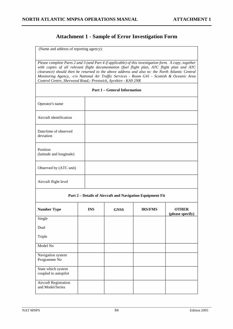
NORTH ATLANTIC MNPSA OPERATIONS MANUAL ATTACHMENT 1
NAT MNPS 84 Edition 2005
Attachment 1 - Sample of Error Investigation Form
(Name and address of reporting agency): Please complete Parts 2 and 3 (and Part 4 if applicable) of this investigation form. A copy, together with copies of all relevant flight documentation (fuel flight plan, ATC flight plan and ATC clearance) should then be returned to the above address and also to: the North Atlantic Central Monitoring Agency, -c/o National Air Traffic Services - Room G41 - Scottish & Oceanic Area Control Centre, Sherwood Road,- Prestwick, Ayrshire - KA9 2NR
Part 1 – General Information
Operator's name
Aircraft identification
Date/time of observed deviation
Position (latitude and longitude)
Observed by (ATC unit)
Aircraft flight level
Part 2 – Details of Aircraft and Navigation Equipment Fit
Number Type
INS
GNSS
IRS/FMS
OTHER
(please specify) Single Dual Triple
Model No
Navigation system Programme No
State which system coupled to autopilot
Aircraft Registration and Model/Series
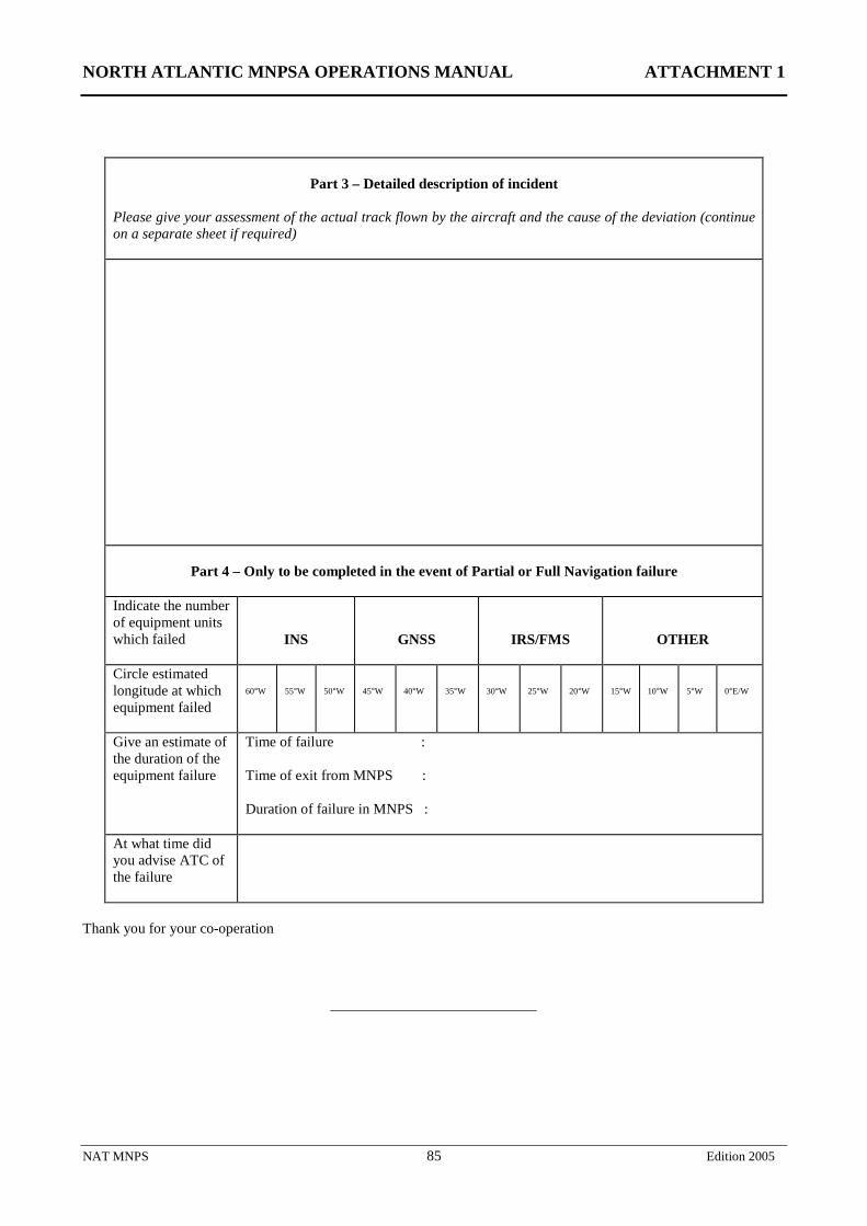
NORTH ATLANTIC MNPSA OPERATIONS MANUAL ATTACHMENT 1
NAT MNPS 85 Edition 2005
Part 3 – Detailed description of incident
Please give your assessment of the actual track flown by the aircraft and the cause of the deviation (continue on a separate sheet if required)
Part 4 – Only to be completed in the event of Partial or Full Navigation failure
Indicate the number of equipment units which failed
INS
GNSS
IRS/FMS
OTHER
Circle estimated longitude at which equipment failed
60°W
55°W
50°W
45°W
40°W
35°W
30°W
25°W
20°W
15°W
10°W
5°W
0°E/W
Give an estimate of the duration of the equipment failure
Time of failure : Time of exit from MNPS : Duration of failure in MNPS :
At what time did you advise ATC of the failure
Thank you for your co-operation
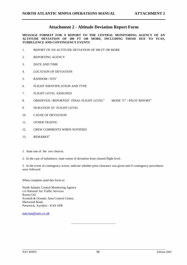
NORTH ATLANTIC MNPSA OPERATIONS MANUAL ATTACHMENT 2
NAT MNPS 86 Edition 2005
Attachment 2 - Altitude Deviation Report Form
MESSAGE FORMAT FOR A REPORT TO THE CENTRAL MONITORING AGENCY OF AN ALTITUDE DEVIATION OF 300 FT OR MORE, INCLUDING THOSE DUE TO TCAS, TURBULENCE AND CONTINGENCY EVENTS 1. REPORT OF AN ALTITUDE DEVIATION OF 300 FT OR MORE 2. REPORTING AGENCY 3. DATE AND TIME 4. LOCATION OF DEVIATION 5. RANDOM / OTS1 6. FLIGHT IDENTIFICATION AND TYPE 7. FLIGHT LEVEL ASSIGNED 8. OBSERVED / REPORTED1 FINAL FLIGHT LEVEL2 MODE “C” / PILOT REPORT1
9. DURATION AT FLIGHT LEVEL 10. CAUSE OF DEVIATION 11. OTHER TRAFFIC 12. CREW COMMENTS WHEN NOTIFIED 13. REMARKS3
1. State one of the two choices. 2. In the case of turbulence, state extent of deviation from cleared flight level. 3. In the event of contingency action, indicate whether prior clearance was given and if contingency procedures were followed When complete send this form to: North Atlantic Central Monitoring Agency c/o National Air Traffic Services Room G41 Scottish & Oceanic Area Control Centre, Sherwood Road, Prestwick, Ayrshire - KA9 2NR [email protected]
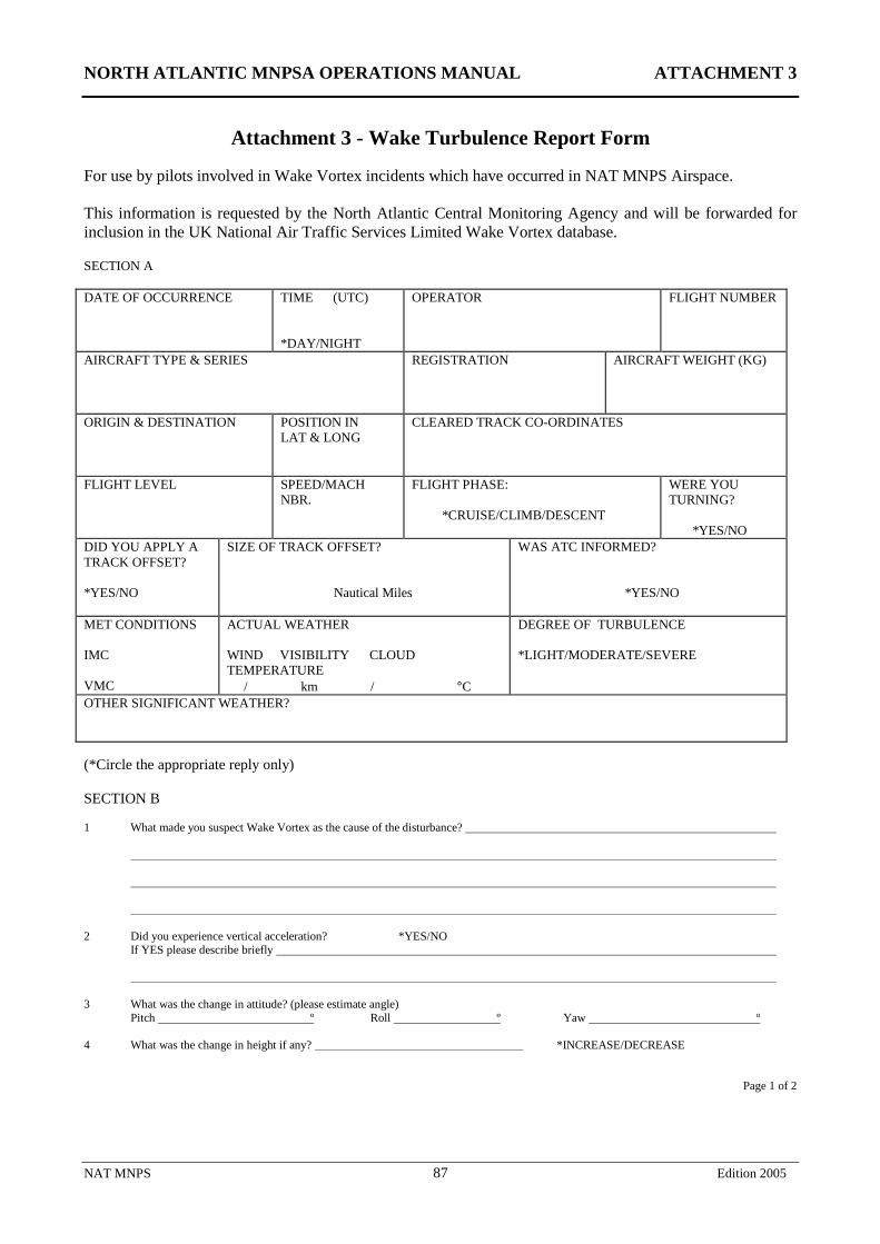
NORTH ATLANTIC MNPSA OPERATIONS MANUAL ATTACHMENT 3
NAT MNPS 87 Edition 2005
Attachment 3 - Wake Turbulence Report Form For use by pilots involved in Wake Vortex incidents which have occurred in NAT MNPS Airspace. This information is requested by the North Atlantic Central Monitoring Agency and will be forwarded for inclusion in the UK National Air Traffic Services Limited Wake Vortex database. SECTION A DATE OF OCCURRENCE TIME (UTC)
*DAY/NIGHT
OPERATOR FLIGHT NUMBER
AIRCRAFT TYPE & SERIES
REGISTRATION AIRCRAFT WEIGHT (KG)
ORIGIN & DESTINATION
POSITION IN LAT & LONG
CLEARED TRACK CO-ORDINATES
FLIGHT LEVEL SPEED/MACH NBR.
FLIGHT PHASE: *CRUISE/CLIMB/DESCENT
WERE YOU TURNING? *YES/NO
DID YOU APPLY A TRACK OFFSET? *YES/NO
SIZE OF TRACK OFFSET? Nautical Miles
WAS ATC INFORMED? *YES/NO
MET CONDITIONS IMC VMC
ACTUAL WEATHER WIND VISIBILITY CLOUD TEMPERATURE / km / °C
DEGREE OF TURBULENCE *LIGHT/MODERATE/SEVERE
OTHER SIGNIFICANT WEATHER? (*Circle the appropriate reply only) SECTION B 1 What made you suspect Wake Vortex as the cause of the disturbance? 2 Did you experience vertical acceleration? *YES/NO If YES please describe briefly 3 What was the change in attitude? (please estimate angle) Pitch º Roll º Yaw º 4 What was the change in height if any? *INCREASE/DECREASE
Page 1 of 2
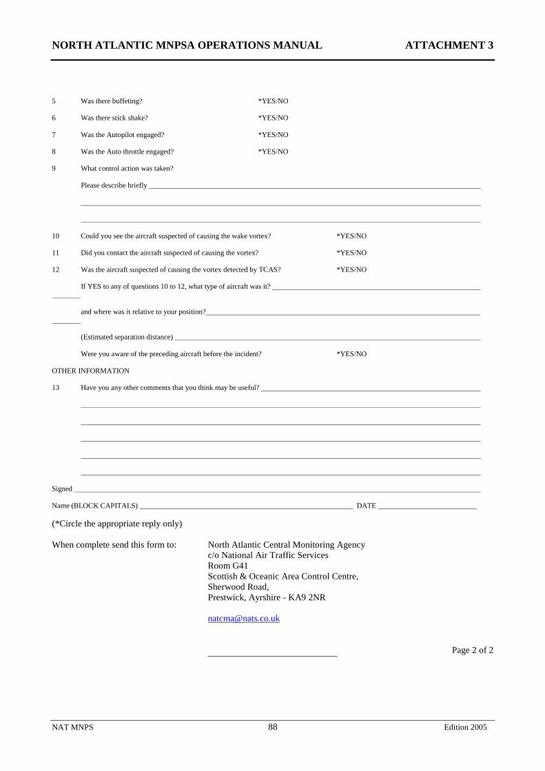
NORTH ATLANTIC MNPSA OPERATIONS MANUAL ATTACHMENT 3
NAT MNPS 88 Edition 2005
5 Was there buffeting? *YES/NO 6 Was there stick shake? *YES/NO 7 Was the Autopilot engaged? *YES/NO 8 Was the Auto throttle engaged? *YES/NO 9 What control action was taken? Please describe briefly 10 Could you see the aircraft suspected of causing the wake vortex? *YES/NO 11 Did you contact the aircraft suspected of causing the vortex? *YES/NO 12 Was the aircraft suspected of causing the vortex detected by TCAS? *YES/NO If YES to any of questions 10 to 12, what type of aircraft was it? and where was it relative to your position? (Estimated separation distance) Were you aware of the preceding aircraft before the incident? *YES/NO OTHER INFORMATION 13 Have you any other comments that you think may be useful? Signed Name (BLOCK CAPITALS) DATE (*Circle the appropriate reply only) When complete send this form to: North Atlantic Central Monitoring Agency
c/o National Air Traffic Services Room G41 Scottish & Oceanic Area Control Centre, Sherwood Road, Prestwick, Ayrshire - KA9 2NR [email protected]
Page 2 of 2
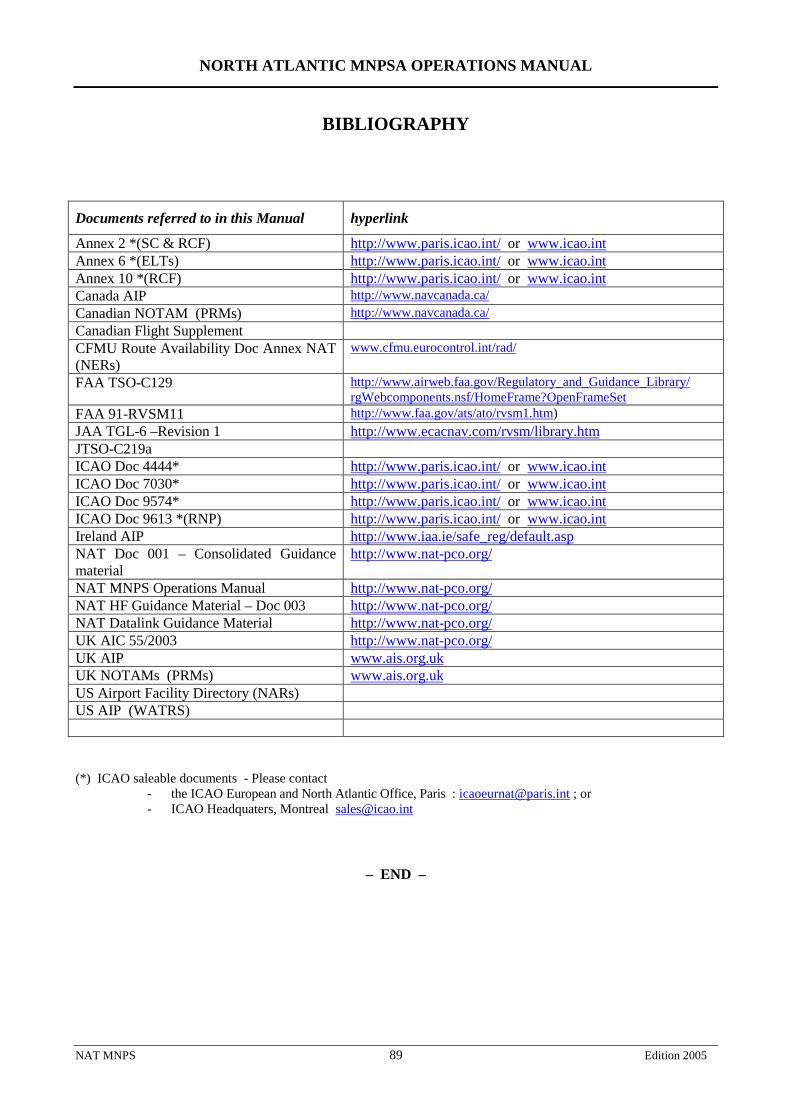
NORTH ATLANTIC MNPSA OPERATIONS MANUAL
NAT MNPS 89 Edition 2005
BIBLIOGRAPHY
Documents referred to in this Manual hyperlink
Annex 2 *(SC & RCF) http://www.paris.icao.int/ or www.icao.int Annex 6 *(ELTs) http://www.paris.icao.int/ or www.icao.int Annex 10 *(RCF) http://www.paris.icao.int/ or www.icao.int Canada AIP http://www.navcanada.ca/ Canadian NOTAM (PRMs) http://www.navcanada.ca/ Canadian Flight Supplement CFMU Route Availability Doc Annex NAT (NERs)
www.cfmu.eurocontrol.int/rad/
FAA TSO-C129 http://www.airweb.faa.gov/Regulatory_and_Guidance_Library/ rgWebcomponents.nsf/HomeFrame?OpenFrameSet
FAA 91-RVSM11 http://www.faa.gov/ats/ato/rvsm1.htm) JAA TGL-6 –Revision 1 http://www.ecacnav.com/rvsm/library.htm JTSO-C219a ICAO Doc 4444* http://www.paris.icao.int/ or www.icao.int ICAO Doc 7030* http://www.paris.icao.int/ or www.icao.int ICAO Doc 9574* http://www.paris.icao.int/ or www.icao.int ICAO Doc 9613 *(RNP) http://www.paris.icao.int/ or www.icao.int Ireland AIP http://www.iaa.ie/safe_reg/default.asp NAT Doc 001 – Consolidated Guidance material
http://www.nat-pco.org/
NAT MNPS Operations Manual http://www.nat-pco.org/ NAT HF Guidance Material – Doc 003 http://www.nat-pco.org/ NAT Datalink Guidance Material http://www.nat-pco.org/ UK AIC 55/2003 http://www.nat-pco.org/ UK AIP www.ais.org.uk UK NOTAMs (PRMs) www.ais.org.uk US Airport Facility Directory (NARs) US AIP (WATRS) (*) ICAO saleable documents - Please contact
- the ICAO European and North Atlantic Office, Paris : [email protected] ; or - ICAO Headquaters, Montreal [email protected]
– END –