Nortel GSM BSS Fundamentals
454
Global System for Mobile Communications (GSM) Nortel GSM BSS Fundamentals — Operating Principles 411-9001-007 .
-
Upload
stefanrott -
Category
Documents
-
view
661 -
download
25
description
Nortel GSM BSS Fundamentals
Transcript of Nortel GSM BSS Fundamentals
Global System for Mobile Communications (GSM)
Nortel GSM BSS Fundamentals— Operating Principles
411-9001-007.

Document status: StandardDocument version: 16.04Document date: 16 October 2006
Copyright © 1999-2006, Nortel NetworksAll Rights Reserved.
Originated in France
The information contained in this document is the property of Nortel Networks. Except as specifically authorizedin writing by Nortel Networks, the holder of this document shall keep the information contained herein confidentialand shall protect same in whole or in part from disclosure and dissemination to third parties and use for evaluation,operation and maintenance purposes only.
You may not reproduce, represent, or download through any means, the information contained herein in any way or inany form without prior written consent of Nortel Networks.
3
Contents
New in this release 11Features 11Other changes 15
Introduction 17
Chapter 1 General operating mechanisms 211.1 Overview of network operations 21
1.1.1 The OMC-R 211.1.2 Major operating principles 21
1.2 BSC 12000HC functional characteristics 251.3 BSC 3000 functional characteristics 261.4 OMC-R features and functions 291.5 Basic definitions 30
1.5.1 OMC-R functional architecture 301.5.2 Objects 311.5.3 Databases 311.5.4 Object classes and instances 331.5.5 Parameters 341.5.6 Operations 341.5.7 Unsolicited messages 35
1.6 Configuration management 351.6.1 Object classes 351.6.2 Managed entities 431.6.3 State parameters 441.6.4 Managed object relationships 461.6.5 Permanent parameter classes 541.6.6 Parameter validity controls 561.6.7 Hardware configuration 571.6.8 BSC 3000 load balancing - estimatedSiteLoad parameter 601.6.9 Number radio site configuration 611.6.10 Basic operations 641.6.11 Secure operation in reparenting 701.6.12 Improved build online performance 721.6.13 PCUSN configuration 72
Global System for Mobile Communications (GSM)Nortel GSM BSS Fundamentals — Operating Principles
411-9001-007 16.04 Standard16.0 16 October 2006
Copyright © 1999-2006, Nortel Networks Nortel Networks Confidential
.
4 Contents
1.7 OMN access management 751.7.1 OMN access management for BSC 12000HC 751.7.2 BSC 3000 OMN access management 81
1.8 OMC-R network configuration 881.8.1 TCP/IP over Ethernet 881.8.2 X25 over a serial link 88
1.9 AMR Overview 891.9.1 BSS capacity 901.9.2 Effect of satellite links on AMR services link adaptation mechanism 901.9.3 AMR based on traffic 901.9.4 FACCH repetition 91
1.10 Software management 911.10.1 Definitions 911.10.2 BSC 12000HC software management 931.10.3 BSC 3000 software management 1061.10.4 Consulting BSS software versions 1201.10.5 BSC/OMC-R exchanges 1201.10.6 Centralized downloading of BTS by BSC 1211.10.7 Automatic downloading of DRX software 1251.10.8 Improved upgrade performance 127
1.11 SMS-CB management 1271.11.1 Overview 1271.11.2 Principles 1281.11.3 Message management 1281.11.4 Broadcast management 130
1.12 Performance management 1321.12.1 Overview 1321.12.2 Permanent observations 1371.12.3 Performance Monitor observation 1501.12.4 Temporary observation for BSC 12000HC only 1531.12.5 Trace management 1571.12.6 OMC-R message store 1631.12.7 Performance management reporting 1671.12.8 Obtaining distributions on radio measurements 1681.12.9 Call drop analysis 1711.12.10 Generating an Interference Matrix 174
1.13 Fault management 1771.13.1 Definitions 1771.13.2 Overview 1771.13.3 Unsolicited message management 1801.13.4 Alarm management 1871.13.5 Alarm criteria 1911.13.6 Man-machine commands 195
Global System for Mobile Communications (GSM)Nortel GSM BSS Fundamentals — Operating Principles
411-9001-007 16.04 Standard16.0 16 October 2006
Copyright © 1999-2006, Nortel Networks Nortel Networks Confidential
.
Contents 5
1.13.7 Alarm counters and relays 2001.13.8 PCUSN interface 201
1.14 Preventive maintenance management 2021.14.1 BSC 12000HC 2021.14.2 PCUSN 204
1.15 Network graphic management 2041.15.1 Network display 2041.15.2 State management 220
1.16 Security management 2311.16.1 Overview 2311.16.2 Service access management 2321.16.3 Work session management 2381.16.4 Special cases 2411.16.5 Output classes 242
1.17 Command file management 2431.17.1 Overview 2431.17.2 Operating principles 2431.17.3 File Execution time Duration (FED) 2491.17.4 Command file directory management 249
1.18 User facilities 2501.18.1 Overview 2501.18.2 System log services 2501.18.3 System time management 2531.18.4 Job scheduler 2551.18.5 Inter-user mail facility 2591.18.6 On-line help 260
1.19 Synchronization 2601.19.1 BTS Synchronization 2601.19.2 Network synchronization 262
1.20 Introduction to OMC-R data server (SDO) 2631.21 Network level presence identification of eDRX, ePA and HePA 264
1.21.1 Overview 2641.21.2 Operating principles 2651.21.3 Impacts 266
1.22 Disaster recovery 267
Chapter 2 GSM evolutions 2692.1 General Packet Radio Service (GPRS) 269
2.1.1 Introduction 2692.1.2 Principles 2692.1.3 Implementation 2702.1.4 OA&M interfaces evolution 2702.1.5 GSM/GPRS/EGPRS TSs dynamic sharing 2712.1.6 RLC polling improvement 273
Global System for Mobile Communications (GSM)Nortel GSM BSS Fundamentals — Operating Principles
411-9001-007 16.04 Standard16.0 16 October 2006
Copyright © 1999-2006, Nortel Networks Nortel Networks Confidential
.
6 Contents
2.1.7 TBF establishment improvements 2742.1.8 GPRS TBF establishment improvement: one phase access 2762.1.9 Extended uplink TBF 2772.1.10 Full Keep Alive 2782.1.11 Disabling TBF Keep Alive during GMM procedure 2782.1.12 GPRS sleepy cells Step 1: automatic detection and recovery 2792.1.13 Configure sending of SI13 and SI2Quater on Ext or Normal BCCH 2792.1.14 PS paging duplication on BSC 2812.1.15 GRPS/EDGE Suspend and Resume 2812.1.16 Implementing Network Mode of Operation 1 (NMO1) 281
2.2 Base Station Controller 3000 and TransCoder Unit 3000 (BSC 3000 and TCU3000) 286
2.2.1 OMN interfaces evolution 2862.3 Location services 291
2.3.1 Introduction 2912.3.2 NSS-based solution 2912.3.3 Tandem-hybrid solution 2922.3.4 BSS-based solution 2942.3.5 Location methods 3002.3.6 A-GPS Assistance data support 303
2.4 EDGE 3032.4.1 Introduction 3032.4.2 Data backhaul 3042.4.3 TDMA selection 3042.4.4 Link adaptation 3062.4.5 Dynamic allocation 3062.4.6 ARQ window management and compressed bitmap feature 3072.4.7 DL incremental redundancy 3072.4.8 Configuration 3082.4.9 Dynamic Agprs & EDGE: Joker handling algorithm 3092.4.10 Rules applicable to EDGE from V15.1 310
2.5 Wireless Priority Service 3112.5.1 Introduction 3112.5.2 Queuing services 3122.5.3 Public access bandwidth protection 3122.5.4 Directed retry without queuing activation feature 3122.5.5 Access class barring 313
2.6 GSM for Railways (GSM-R) 3152.6.1 Introduction 3152.6.2 Advanced Speech Call Items (ASCI) 3162.6.4 Hardware constraints 3182.6.5 Features implemented 3182.6.6 Channel Release on BTS after Abis failure 321
Global System for Mobile Communications (GSM)Nortel GSM BSS Fundamentals — Operating Principles
411-9001-007 16.04 Standard16.0 16 October 2006
Copyright © 1999-2006, Nortel Networks Nortel Networks Confidential
.
Contents 7
Chapter 3 Radio configuration principles 3233.1 Introduction 3233.2 Dictionary of objects 324
3.2.1 The omc object 3243.2.2 The md subtree 3243.2.3 The network subtree 3283.2.4 The bsc subtree 3293.2.5 The transcoder subtree 3313.2.6 The btsSiteManager subtree 3323.2.7 The multiple site object 3363.2.8 The software object 3363.2.9 The short message object 3363.2.10 Inter-object relationships 337
3.3 Radio entity management principles 3393.3.1 BSC management 3393.3.2 PCM link management 3403.3.3 LAPD link management 3483.3.4 Concentric cells 3533.3.5 Software management 355
3.4 Radio measurement processing 3553.4.1 Principles 3563.4.2 Configuration parameters 3563.4.3 Definitions 3583.4.4 Measurement processing 3583.4.5 New power control algorithms 365
3.5 Radio cell selection and reselection 3673.5.1 Principles 3673.5.2 Configuration parameters 3673.5.3 Selection management 3693.5.4 Reselection management 3703.5.5 Network assisted cell change for release 4 MS 372
3.6 Handover management 3723.6.1 Principles 3723.6.2 Configuration parameters 3773.6.3 Processing algorithms 3833.6.4 Concentric cells 3893.6.5 Neighbor cells 3923.6.6 Microcells 398
3.7 Power control 3993.7.1 Principles 3993.7.2 Configuration parameters 4003.7.3 Processing algorithms 401
Global System for Mobile Communications (GSM)Nortel GSM BSS Fundamentals — Operating Principles
411-9001-007 16.04 Standard16.0 16 October 2006
Copyright © 1999-2006, Nortel Networks Nortel Networks Confidential
.
8 Contents
3.7.4 Maximum transmission power 4033.8 Call monitoring 415
3.8.1 Principles 4153.8.2 Mobile distance control 4153.8.3 Radio link monitoring 416
3.9 Radio resource allocation 4183.9.1 Principles 4183.9.2 Configuration parameters 4183.9.3 Priority management 4193.9.4 Queuing management 4193.9.5 Processing algorithm 4203.9.6 Concentric cells 4203.9.7 Idle radio channel classification 421
3.10 Frequency hopping management 4213.10.1 Configuration parameters 4213.10.2 Frequency hopping management principles 4223.10.3 Frequency redefinition process 4233.10.4 Time slot reconfiguration 424
3.11 Frequency plan change for large scale networks 4243.12 Defense and reconfiguration 424
3.12.1 Configuration parameters 4253.12.2 Defense 4253.12.3 Reconfiguration 426
3.13 Uplink mapping 4283.13.1 Principles 4283.13.2 Prerequisites 4283.13.3 Configuration parameters 4283.13.4 Measurement processing 429
3.14 Hardware constraints (from V14 release): 430
Appendix A BTS TEI NUMBERING RULES 431A.1 S2000 BTSs 431A.2 S4000 BTSS 431A.3 S2000 H/L BTSs 431A.4 e-cell BTSs 431
A.4.1 Monoband configurations 431A.4.2 Dualband BCF configurations with monoband cells 431
A.5 S8002 BTSs 432A.6 S8000 Outdoor/Indoor BTSs 432
A.6.1 Monoband S8000 BTS configurations 432A.6.2 Dualband BCF S8000 BTS configurations with dualband cells 433A.6.3 Dualband BCF S8000 BTS configurations with monoband cells 435A.6.4 Dualband CBCF S8000 BTS configurations with dualband cells 437A.6.5 Dualband CBCF S8000 BTS configurations with monoband cells 438
Global System for Mobile Communications (GSM)Nortel GSM BSS Fundamentals — Operating Principles
411-9001-007 16.04 Standard16.0 16 October 2006
Copyright © 1999-2006, Nortel Networks Nortel Networks Confidential
.
Contents 9
A.7 S12000 Outdoor/Indoor BTSs 440A.7.1 Monoband S12000 BTS configurations 440A.7.2 Dual band S12000 BTS configurations with dualband cells 442A.7.3 Dualband CBCF S12000 BTS configurations with dualband sites 445
A.8 BTS 18000 446A.8.1 TEI Numbering 446A.8.2 TEI Mapping 447A.8.3 Location of shelves 448
Appendix B GSM EQUIVALENCES 449
FiguresFigure 1 Position of the OMC-R in the mobile network 22Figure 2 OMC-R design 31Figure 3 Operations database and application database 33Figure 4 Object main tree structure 37Figure 5 OMC subtree objects 37Figure 6 MD subtree objects 38Figure 7 Network subtree objects 39Figure 8 BSC 12000HC subtree objects 40Figure 9 BSC 3000 subtree objects 40Figure 10 btsSiteManager subtree objects 41Figure 11 Equipment configuration 48Figure 12 Agprs interface configuration 49Figure 13 Radio resource configuration (Abis interface) 50Figure 14 Ater and A interface configuration for BSC/TCU 2G and BSC/TCU
3000 51Figure 15 Object enabling sequence 52Figure 16 PCUSN in the BSS subsystem 74Figure 17 OMC-R communication equipment for BSC 12000HC 77Figure 18 OMC-R communication equipment for BSC 3000 84Figure 19 OMC-R WAN 88Figure 20 Software management (specific BSC/TCU 2G) on the man-machine
interface 93Figure 21 Software management (specific BSC/TCU 3000) on the man-machine
interface 107Figure 22 BSC 12000HC/OMC-R exchanges 121Figure 23 Observation file store and transfer process 145Figure 24 Threshold crossing detection 149Figure 25 Information concentration for maintenance purposes 178Figure 26 Layout of the OMC-R browser 205Figure 27 Logical mode screen hierarchy 215Figure 28 Physical mode screen hierarchy 216Figure 29 Mode display selection on the OMC-R browser 218Figure 30 Logical / Physical mode swapping scheme 219Figure 31 Simple modelled object 221Figure 32 Expandable modelled object 221Figure 33 Container object 222Figure 34 OMC-R and MD-R graphic objects 222Figure 35 Flexible group graphic object 223
Global System for Mobile Communications (GSM)Nortel GSM BSS Fundamentals — Operating Principles
411-9001-007 16.04 Standard16.0 16 October 2006
Copyright © 1999-2006, Nortel Networks Nortel Networks Confidential
.
10 Contents
Figure 36 Physical view graphic object 223Figure 37 Link graphic object 223Figure 38 Link group graphic object 223Figure 39 bscMdInterface dedicated graphic object 223Figure 40 Off-page connector graphic object 224Figure 41 Off-page selector graphic object 224Figure 42 State display 225Figure 43 Graphic object with alarms 226Figure 44 Graphic summary count symbolic 226Figure 45 Selection display 230Figure 46 Interfaces associated with the NMO1 feature 282Figure 47 MS not attached to GPRS - CS paging through A interface 283Figure 48 MS attached to GPRS - paging through Gs, Gb, and Agprs 284Figure 49 MS attached to GPRS - in GMM ready state 285Figure 50 LCS logical architecture 292Figure 51 Standard LCS network architecture 295Figure 52 Lb direct SMLC configuration 296Figure 53 Lb via MSC STP configuration 297Figure 54 Signalling part of the data model 299Figure 55 Inter-object relationships 338Figure 56 1st example of drop and insert configuration: chained BTSs and no
redundant CPCMI board 346Figure 57 2nd example of drop and insert configuration: looped BTSs with
redundant CPCMI boards 347Figure 58 LAPD link management in a BSS (with BSC 12000HC) 352Figure 59 Interference level calculations 365Figure 60 Handover cases 376Figure 61 Inter-zone handover 391Figure 62 Dualband cell handover cases 394
TablesTable 1 Order of creating objects in the BDE 53Table 2 Static data maximum configuration with BSC/TCU 2G. 56Table 3 Static data maximum configuration with BSC/TCU 3000 57Table 4 BSC 12000HC configurations managed on the OMC-R 58Table 5 BSC 12000HC architecture controls 58Table 6 BTS controls for BSC 12000HC 62Table 7 BTS controls for BSC 3000 63Table 8 Correspondence between DRX hardware and EFT name 126Table 9 Alarm display evolution 227Table 10 Maximum number of DS0 per TRX 311Table 11 Handover causes and types 375Table 12 e-cell bsTxPwrMax versus coupling system 406Table 13 DLU attenuation versus coupling system 407Table 14 DLU attenuation versus coupling system for BTS 18000 408Table 15 Pr vs bsTxPwrMax (Part 1) 409Table 16 Pr vs bsTxPwrMax (Part 2) 411Table 17 Coupling loss mean values 413Table 18 TRX TEI Numbering 447Table 19 ABM TEI Numbering 447
Global System for Mobile Communications (GSM)Nortel GSM BSS Fundamentals — Operating Principles
411-9001-007 16.04 Standard16.0 16 October 2006
Copyright © 1999-2006, Nortel Networks Nortel Networks Confidential
.
11
New in this release
The following sections detail what’s new in the Nortel GSM BSSFundamentals Operating Principles guide for release V16.0. See thefollowing sections for information about feature changes:
Features• PM1270 - TDMA based counters (15405) (v16.01)
— This feature provides TDMA based counters that give a more preciseview of the quality of the network. TDMA based counters provide thefollowing metrics at the TDMA level:
– TCH drop ratio normalized either per Erlang or per TCHsuccessfully seized
– TCH seizure failure ratio normalized per TCH seizure attempt
– Handover failure rate
– Layer one average performance avg Rxlev, Path balance,RxQual, FER, …
— Modified Section 1.12.2.3 "Permanent observation reportavailability" (page 139).
• OMC-R OAM SW Delivery on DVD (26674) (v16.01)
— This feature replaces the current SW delivery done on tapes bya delivery on DVD. The Workstation must have a DVD reader. Itreduces the number of media required in the software delivery andreduces the installation time.
— Modified Section 1.10 "Software management" (page 91).
• OMC-R Time Synchronization from an external NTP source (27018)(v16.01)
— This feature allows the time synchronization of the local OMC-Rserver clock at the OS level thanks to the Network Time Protocol
Global System for Mobile Communications (GSM)Nortel GSM BSS Fundamentals — Operating Principles
411-9001-007 16.04 Standard16.0 16 October 2006
Copyright © 1999-2006, Nortel Networks Nortel Networks Confidential
.
12 New in this release
(NTP). NTP uses its own time reference (similar to being based onGMT). The customer must provide the NTP server.
— Modified Section 1.18.3.4 "Time server" (page 254).
• Capacity increase for SF V890 (27817) (v16.01)
— This feature introduces a UHC (Ultra High Capacity) for a SF V890configuration to be able to manage 40 BSCs and 4800 cells.
— Modified Section 1.4 "OMC-R features and functions" (page 29).
• Call Drop analysis – interface evolution V16.0 (29043) (v16.01)
— This feature introduces some evolutions in the existing Call Dropanalysis features.
— Modified Section 1.12.9 "Call drop analysis" (page 171).
• Distributions on Radio Measurements – interface evolution V16.0(29042) (v16.01)
— This feature introduces some evolutions in the existing Distributionson Radio Measurements feature.
— Modified Section 1.12.8 "Obtaining distributions on radiomeasurements" (page 168)
• WPS for PCUSN configuration (29818) (v16.01)
— This feature introduces WPS (Wireless Provisioning Server) as areplacement for the configuration functions previously offered bythe PCUengCONF tool).
— Updated Section 1.6.13 "PCUSN configuration" (page 72).
• BSC 3000 support of BTS SW background downloading (25316)(v16.01)(v16.02)
— This feature allows new software to be downloaded to a BTS whilethis BTS carries GSM/GPRS traffic (on a live network).
— Inserted Section 1.10.3.6 "BTS software background downloading"(page 116).
• Channel release policy on BTS after Abis failure (22810) (v16.01)(v16.02)
— This feature improves BTS behavior on Abis link failure (includingBSC failure) by stopping BTS broadcast of BCCH and SACCH.
— Inserted Section 2.6.6 "Channel Release on BTS after Abis failure"(page 321)in Section 2.6 "GSM for Railways (GSM-R)" (page 315).
Global System for Mobile Communications (GSM)Nortel GSM BSS Fundamentals — Operating Principles
411-9001-007 16.04 Standard16.0 16 October 2006
Copyright © 1999-2006, Nortel Networks Nortel Networks Confidential
.
Features 13
• BSC 3000 support for Lb interface (multi DPC) to Nortel SMLC throughNortel and other vendors’ MSC (20365)(v16.01)
— This feature introduces the support of the Lb interface on the BSC3000.
— Re-organized Section 2.3 "Location services" (page 291) andinserted Section 2.3.4 "BSS-based solution" (page 294).
• U-TDOA support on the BSS (BSC 3000 Lb only) (24917) (v16.01)
— This feature provides support for the LCS messaging required forLCS U-TDOA (Uplink-Time Difference of Arrival) on the BSC 3000.
— Re-organized Section 2.3 "Location services" (page 291) , insertedSection 2.3.5 "Location methods" (page 300), and modified Section2.3.5.4 "U-TDOA method" (page 302).
• GPRS/EDGE cell reselection improvement NACC for R4 MS (22859)(v16.01)
— This feature enables the network to assist the MS during cellreselection, thereby, reducing the service interruption at cell change.
— Updated Section 3.5.2 "Configuration parameters" (page 367)
— Inserted Section 3.5.5 "Network assisted cell change for release4 MS" (page 372).
• EDGE: Minimum number of joker TS on Agprs set by the operator(26954) (v16.01)
— This feature enables the operator to define a minimum number ofjokers that cannot be pre-empted by the Dynamic Agprs feature.
— Updated Section 2.4.9 "Dynamic Agprs & EDGE: Jokerhandling algorithm" (page 309)
• BSC defense procedures for centralized downloading (29213) (v16.01)
— This feature brings improved BSC defense for centralizeddownloading.
— Updated Section 1.10.6 "Centralized downloading of BTS by BSC"(page 121)
• PM1398 Switch interference matrix (16411) (v16.01) (v16.02)
— This feature enables Interference Matrix data to be collected. AnInterference Matrix is used in frequency planning.
— Updated Section 1.12 "Performance management" (page 132)byinserting Section 1.12.10 "Generating an Interference Matrix" (page174).
Global System for Mobile Communications (GSM)Nortel GSM BSS Fundamentals — Operating Principles
411-9001-007 16.04 Standard16.0 16 October 2006
Copyright © 1999-2006, Nortel Networks Nortel Networks Confidential
.
14 New in this release
— Updated Section 1.20 "Introduction to OMC-R data server (SDO)"(page 263)
• FACCH repetition (30296) (v16.02)
— This feature enables the BTS to re-transmit the FACCH (FastAssociated Control CHannel) frames in the downlink without waitingfor the acknowledgement from the mobile. This helps to secure thehandover procedure in poor radio conditions (with AMR FR).
— Inserted Section 1.9.4 "FACCH repetition" (page 91)
• Tx Power Offset for Signalling Channels (30293) (v16.02)
— This features enables the BTS to use a power offset to transmitsignalling bursts to increase the robustness of the signallingchannels (FACCH and SACCH) in the downlink. This can help avoidcall drops in situations where the radio conditions are deteriorating.
— Updated Section 3.7.2 "Configuration parameters" (page 400)
— Inserted Section 3.7.4.3 "Tx Power Offset for Signalling Channels"(page 414)
• BTS 18000 MPRM differentiation at the OMC-R (30713) (v16.02)
— This features enables the OMC-R to distinguish MPRMs from RMs.
— Updated Table 8 "Correspondence between DRX hardware and EFTname" (page 126)
• Radio measurement distribution post-processing product introduction(30494)(v16.02)
— This feature provides a tool to process the data collected by theRadio Measurement Distribution (RMD) feature.
— Inserted Section 1.12.8.6 "Post-processing of data collected" (page169)
• Call drop analsis post-processing (28796)(v16.02)
— This feature provides a tool to process the data collected by theCall Drop Analysis (CDA) feature.
— Inserted Section 1.12.9.6 "Post-processing of data collected" (page172)
• Interference matrix port-processing product introduction (30769)(v16.02)
— This feature provides a tool to process the data collected by theInterference matrix (IM) feature.
Global System for Mobile Communications (GSM)Nortel GSM BSS Fundamentals — Operating Principles
411-9001-007 16.04 Standard16.0 16 October 2006
Copyright © 1999-2006, Nortel Networks Nortel Networks Confidential
.
Other changes 15
— Inserted Section 1.12.10.6 "Post-processing of data collected"(page 175)
• SDO data compression (30308) (v16.02)
— This feature provides a tool that automatically compresses SDOdata files.
— Updated Section 1.20 "Introduction to OMC-R data server (SDO)"(page 263)
• BSC support for Lb interface to SMLC through A-link (33160) (v16.04)
— This feature allows the A interface and the MSC to be used as anSTP to convey SS7 traffic between the BSC and the SMLC. Thisfeature is an enhancement of the feature 20365 (referenced above).
— Updated the description of the BSS-based solution (locationservices) in
Other changesSee the following sections for information about changes that are notfeature-related:
• Removed information on BSC 12000 due to EOL (End Of Life).
• Replaced all occurrences of BSC 2G with BSC 12000HC.
• Updated the directory name for configuration files in Section 1.12.3.6"Consulting Performance Monitor observation reports" (page 152)
• Updated the directory name for manufacturer’s files in Section 1.12.4.6"Consulting temporary observation reports" (page 156)
Global System for Mobile Communications (GSM)Nortel GSM BSS Fundamentals — Operating Principles
411-9001-007 16.04 Standard16.0 16 October 2006
Copyright © 1999-2006, Nortel Networks Nortel Networks Confidential
.

16 New in this release
Global System for Mobile Communications (GSM)Nortel GSM BSS Fundamentals — Operating Principles
411-9001-007 16.04 Standard16.0 16 October 2006
Copyright © 1999-2006, Nortel Networks Nortel Networks Confidential
.
17
Introduction
This Operations and Maintenance Center - Radio (OMC-R) operatingNTP contains principles on general operating mechanisms and radioconfiguration.
PrerequisitesUsers must be familiar with radio and networking principles.
< 000 > : Nortel GSM BSS Documentation Roadmap
They must also be familiar with the following NTPs:
< 001 > : Nortel GSM BSS Overview
< 006 > : Nortel GSM OMC-R Fundamentals
< 032 > : Nortel GSM OMC-R Routine Maintenance and Troubleshooting
< 034 > : Nortel GSM BSS Configuration — Operating Procedures
< 124 > : Nortel GSM BSS Parameter Reference
< 125 > : Nortel GSM BSS Performance Management — ObservationCounters Dictionary
< 128 > : Nortel GSM OMC-R Commands Reference — Objects and Faultmenus
< 129 > : Nortel GSM OMC-R Commands Reference — Configuration,Performance, and Maintenance menus
< 130 > : Nortel GSM OMC-R Commands Reference — Security,Administration, SMS-CB, and Help menus
< 133 > : Nortel GSM BSS Performance Management — ObservationCounters Fundamentals
Global System for Mobile Communications (GSM)Nortel GSM BSS Fundamentals — Operating Principles
411-9001-007 16.04 Standard16.0 16 October 2006
Copyright © 1999-2006, Nortel Networks Nortel Networks Confidential
.
18 Introduction
< 211 > : Nortel GSM PCUSN Performance Management — ObservationCounters Dictionary
NavigationChapter 1 "General operating mechanisms" (page 21) describes the majoroperating principles under the following headings:
• Description of the position of the OMC-R in the mobile network (seeSection 1.1 "Overview of network operations" (page 21)).
• Review of BSC 12000HC functions (see Section 1.2 "BSC 12000HCfunctional characteristics" (page 25)).
• Review of BSC 3000 functions (see Section 1.3 "BSC 3000 functionalcharacteristics" (page 26)).
• Review of OMC-R functions (see Section 1.4 "OMC-R features andfunctions" (page 29)).
• Basic definitions (see Section 1.5 "Basic definitions" (page 30)).
• Configuration Management which is based on the operating objectmodel (see Section 1.6 "Configuration management" (page 35)).
• OMN Access Management which enables BSS/OMC-R link connectionand monitoring (see Section 1.7 "OMN access management" (page75)).
• AMR management which manages the half and full rate (see Section1.9 "AMR Overview" (page 89)).
• Software Management which manages BSS software applications (seeSection 1.10 "Software management" (page 91)).
• SMS-CB Management which provides unacknowledged, shortmessage broadcast facilities in radio cells (see Section 1.11 "SMS-CBmanagement" (page 127)).
• Performance Management which is based on observation countercollection (see Section 1.12 "Performance management" (page 132)).
• Fault Management which is based on the feedback of notifications to theOMC-R (see Section 1.13 " Fault management" (page 177)).
• Preventive Maintenance management which is based on configurableplug-in tests on BSS sub-systems (see Section 1.14 "Preventivemaintenance management" (page 202))
• State Management which provides a graphic aid for monitoring thenetwork (see Section 1.15 "Network graphic management" (page 204)).
• Security Management which controls user access to OMC-R servicesand monitors their work sessions (see Section 1.16 "Securitymanagement" (page 231)).
Global System for Mobile Communications (GSM)Nortel GSM BSS Fundamentals — Operating Principles
411-9001-007 16.04 Standard16.0 16 October 2006
Copyright © 1999-2006, Nortel Networks Nortel Networks Confidential
.
Navigation 19
• Command File Management which provides network configurationor reconfiguration facilities (see Section 1.17 "Command filemanagement" (page 243)).
• User Facilities which allows users to consult the system logs, managethe system reference time, schedule jobs, and provides access tointer-user messaging and on-line help (see Section 1.18 "Userfacilities" (page 250)).
• Synchronization which allows users to synchronize a BTS from anotherBTS or using GPS (see Section 1.19 "Synchronization" (page 260)).
• OMC-R Data Server: It is used to export OMC-R data to externalapplications (see Section 1.20 "Introduction to OMC-R data server(SDO)" (page 263)).
• Network level presence identification which consists in finding a way todifferentiate in a system view eDRX from DRX and ePA and HePA fromPA (see Section 1.21 "Network level presence identification of eDRX,ePA and HePA" (page 264)).
Chapter 2 "GSM evolutions" (page 269) describes optional GSM extensions:
• GPRS (General Packet Radio Service)
• GSM-R (ASCI features)
• BSC 3000 and TCU 3000
• Location Services
Chapter 3 "Radio configuration principles" (page 323) introduces BSS radioconfiguration principles. It describes the relations between radio operatingparameters and the effects on the BSS.
Global System for Mobile Communications (GSM)Nortel GSM BSS Fundamentals — Operating Principles
411-9001-007 16.04 Standard16.0 16 October 2006
Copyright © 1999-2006, Nortel Networks Nortel Networks Confidential
.

20 Introduction
Global System for Mobile Communications (GSM)Nortel GSM BSS Fundamentals — Operating Principles
411-9001-007 16.04 Standard16.0 16 October 2006
Copyright © 1999-2006, Nortel Networks Nortel Networks Confidential
.
21
Chapter 1General operating mechanisms
1.1 Overview of network operations1.1.1 The OMC-R
The OMC-R is the Operations and Maintenance Center for the BSS Radiosubsystem.
A Base Station Subsystem (BSS) includes a Base Station Controller (BSC)connected:
• to TransCoding Units (TCUs) for access to the MSC
• to Packet Control Unit Support Node (PCUSN) for access to the SGSN(Serving GPRS Support Node)
In addition, the BSC manages a group of Base Transceiver Stations (BTSs).
The BSS and OMC-R are organized in a hierarchical tree structure:
• A BSC can manage several BTSs, but a BTS is connected to only oneBSC.
• A BSC can be connected to several TCUs, but a TCU is connected toonly one BSC.
• An OMC-R can manage several BSCs, but a BSC is connected to onlyone OMC-R.
The BSCs and the OMC-R in the Public Land Mobile Network (PLMN) areconnected via the operations and maintenance network interface (OMN).
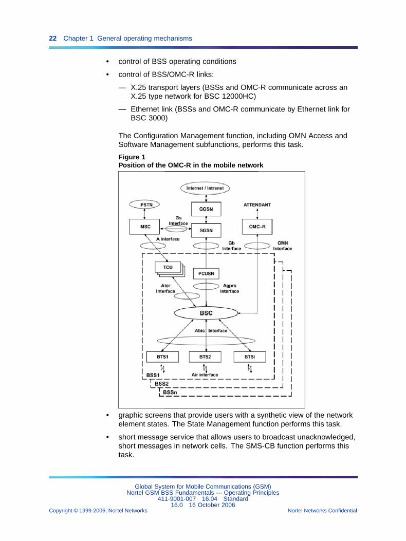
Position of the OMC-R in the mobile network shows the position of theOMC-R in the mobile network.
1.1.2 Major operating principlesThe OMC-R provides the following services to operate a digital mobilenetwork:
• hardware and software resource management
Global System for Mobile Communications (GSM)Nortel GSM BSS Fundamentals — Operating Principles
411-9001-007 16.04 Standard16.0 16 October 2006
Copyright © 1999-2006, Nortel Networks Nortel Networks Confidential
.
22 Chapter 1 General operating mechanisms
• control of BSS operating conditions
• control of BSS/OMC-R links:
— X.25 transport layers (BSSs and OMC-R communicate across anX.25 type network for BSC 12000HC)
— Ethernet link (BSSs and OMC-R communicate by Ethernet link forBSC 3000)
The Configuration Management function, including OMN Access andSoftware Management subfunctions, performs this task.
Figure 1Position of the OMC-R in the mobile network
• graphic screens that provide users with a synthetic view of the networkelement states. The State Management function performs this task.
• short message service that allows users to broadcast unacknowledged,short messages in network cells. The SMS-CB function performs thistask.
Global System for Mobile Communications (GSM)Nortel GSM BSS Fundamentals — Operating Principles
411-9001-007 16.04 Standard16.0 16 October 2006
Copyright © 1999-2006, Nortel Networks Nortel Networks Confidential
.
1.1 Overview of network operations 23
• network observations that provide users with the information required tomonitor operations in order to optimize performances. The PerformanceManagement function performs this task.
• network maintenance repairs, malfunctions, and system failures. TheOMC-R saves all the information it receives and analyzes it in real timeor stores it for a later time. It sends alarm event messages to users tofacilitate equipment reconfiguration and the analysis of test results. TheFault Management function performs this task.
• network preventive maintenance. The OMC-R enables the userto manage growing networks and to anticipate equipment failures,outages, and quality of service deterioration. It allows the user toconfigure, schedule and activate preventive maintenance tests onBSS sub-systems and to view the associated results. The PreventiveMaintenance modules (one module for each test) perform this task.They can be installed as plug-ins without any OMC-R restart.
• network protection which consists of controlling system users’ accessrights. Only a limited number of users can access all OMC-R operations.The Security Management function performs this task.
• network operations services that optimize user working conditions. TheCommand File Manager and User Facilities provide these services.
• To facilitate the commissioning of new BSS versions when hardware andsoftware are upgraded, the OMC-R provides an effective File TransferService with the BSSs that allow users to manage configuration filesfrom the OMC-R. The Software Management function uses this serviceto manage software and the Performance Management function tocollect certain types of observation data.
The OMC-R operations require the administration of its own resources:
• The administration task consists of organizing its hardware and softwareentities (and their use) to archive and restore the managed systemdata and specific OMC-R application data required to monitor its ownhardware and software operations. The OMC Administration functionperforms this task.
The OMC-R Data Server, or SDO, is used to export OMC-R data to externalapplications.
The Man-Machine Interface (MMI), developed for network management,provides a user-friendly communication interface. The MMI is describedin NTPs <128> to < 130 >.
This NTP reviews the BSC and OMC-R digital mobile network managementfunctions and details the major operating principles, apart from the OMCAdministration function which is described in the NTP < 006 >.
Global System for Mobile Communications (GSM)Nortel GSM BSS Fundamentals — Operating Principles
411-9001-007 16.04 Standard16.0 16 October 2006
Copyright © 1999-2006, Nortel Networks Nortel Networks Confidential
.
24 Chapter 1 General operating mechanisms
OMC-R centralized installation and upgrade service feature Thisfeature was introduced in V15.0 and is used for OMC-R installations andupgrades. It is based on Sun MicrosystemsTM JumpStart TM, LiveUpgradeand Flash Archive features, which facilitate the installation and upgradeof Sun MicrosystemsTM SolarisTM machines by automating JumpStartTM,performing Operating System Upgrades On-Line (LiveUpgrade) andspeeding-up the installation and upgrade phase (Flash Archive). Coupledwith a GUI sequencer, this feature offers a full "Hands Free" efficient andautomatic installation and upgrade package for the entire OMC-R system.Additional information for this feature is available in NTP < 006 >.
OMC-R Solaris jumpstart automated installation feature This featurewas introduced in V15.0 and is an automatic installation process available inthe Sun MicrosystemsTM SolarisTM operating environment. It allows systemadministrators to categorize machines on their network and automaticallyinstall systems based on the category to which a system belongs. TheSolarisTM JumpStartTM Automated Installation feature provides the systemadministrator with the following advantages:
• simplifies installations
• speed - Faster than CD-ROM installation
• allows unattended installation
• replication - same systems across the enterprise
All SolarisTM base installations require some basic configuration. WithJumpStartTM, Sun has enabled the system administrator to avoid repetitivetasks associated with bringing a Sun system online.
OMC-R system patch automation feature This feature was introducedin V15.0 and is used to manage OMC-R system patches automatically. Itwas added to the install_data tool, which is normally used to install and/orapply patches and plug-ins in installed OMC-R configurations. The OMC-Rsystem patch automation feature performs the following functions:
• installs and applies system patches automatically
• performs fallback functions from system patches
• displays the system patch level
The install_data tool performs these functions from an application scriptwhich is delivered with the patch by the Nortel team responsible forsystem patches. The system patch automation feature will be introducedprogressively as system patches are delivered with an application script.
Global System for Mobile Communications (GSM)Nortel GSM BSS Fundamentals — Operating Principles
411-9001-007 16.04 Standard16.0 16 October 2006
Copyright © 1999-2006, Nortel Networks Nortel Networks Confidential
.
1.2 BSC 12000HC functional characteristics 25
The install_data tool will place system patches delivered without anapplication script on the OMC-R active server. Additional information for thisfeature is available in NTP < 006 >.
1.2 BSC 12000HC functional characteristicsThe Base Station Controller provides the following:
• Base Transceiver Station (BTS) management which:
— configures physical paths to control radio transceivers (TRX/DRXs)
— initializes TRX/DRXs and configures channels
— concentrates LAPD signalling with the BTSs
— monitors BTS operations
— reconfigures the BTSs when required
— updates system parameters
• TransCoding Unit (TCU 2G) management which:
— initializes and configures the TCBs
— concentrates LAPD signalling with the TCU 2Gs
— monitors TCU 2G operations
• Radio resource management which:
— controls radio access
— allocates radio channel
— monitors radio channel operations
• Call processing which:
— seizes terrestrial and radio circuits
— switches channels from BTSs to MSC, and vice versa
— packets channels from BTSs to SGSN, and vice versa
• Call sustaining procedure execution which
— processes measurements taken by mobiles and base stations withpreprocessing at BTS level
— controls uplink and downlink power
— performs handovers without loss: such as intra-bss, inter-bss andintra-bts handovers on TCHs and SDCCHs (traffic and signallingchannels)
Global System for Mobile Communications (GSM)Nortel GSM BSS Fundamentals — Operating Principles
411-9001-007 16.04 Standard16.0 16 October 2006
Copyright © 1999-2006, Nortel Networks Nortel Networks Confidential
.
26 Chapter 1 General operating mechanisms
• Message transport from MSC or SGSN to mobiles, and vice versa
• Message transport from SMLC to mobiles, and vice versa
• Operations and maintenance which
— links with an operations and maintenance center (OMC-R)
— executes the operating procedures required by the OMC-R, savesthe procedure data, and distributes to BSS equipment, whennecessary
— saves BSS configurations and software with distribution to therequired entities
• Defense which
— detects failures and malfunctions
— performs local defense by isolating defective equipment to avoidfault propagation
— reconfigures equipment onto redundant equipment. This functionalso includes BSC 12000HC chain switchover and restartprocedures.
1.3 BSC 3000 functional characteristicsThe BSC 3000 provides the following
• Radio resource management which:
— processes radio access
— allocates radio channels (traffic and signalling)
— monitors radio channel operating states
• Call processing which:
— sets up and releases terrestrial and radio links
— transfers messages between the mobile stations and:
– the MSC via TCU 2G or TCU 3000 and the BTS
– the SGSN via PCUSN and the BTS
— commutes the switch channels between BTSs and MSC via TCU3000
— commutes the packet channels between BTSs and SGSN viaPCUSN
• Call sustaining procedures which:
— process measurements from mobile stations and the BTSs
Global System for Mobile Communications (GSM)Nortel GSM BSS Fundamentals — Operating Principles
411-9001-007 16.04 Standard16.0 16 October 2006
Copyright © 1999-2006, Nortel Networks Nortel Networks Confidential
.
1.3 BSC 3000 functional characteristics 27
— launches:
– the power control procedures
– the handover procedures
• BTS management which:
— sets physical channels, to control transceivers (TRX)
— initializes the TRX and sets the channels
— supervises BTS operating states
— provides BTS reconfiguration, if needed
— updates system parameters
• TCU management
• BSC 3000 defense which:
— detects and corrects failures and operating anomalies
— provides local defense by isolating faulty units, to avoid problemspreading
— provides equipment unit reconfiguration using redundant units.These functions include the module switching and restartmechanisms for the BSC 3000.
The BSC 3000 houses the following main systems:
• a cooling system
• an alarm system
• a power system
• a control node
• an interface node
• a PCM switching system
For more information about these systems refer to NTP < 126 >.
The BSC 3000 software architecture is based on a network model ofprocessors called a "core system", which can be tailored to fit into differenthardware structures. The core system is divided into logical process units.A set of modules which house boards and processors provide each logicalunit with the processing power they need.
The main types of processing unit are split up as follows:
• for the control node:
Global System for Mobile Communications (GSM)Nortel GSM BSS Fundamentals — Operating Principles
411-9001-007 16.04 Standard16.0 16 October 2006
Copyright © 1999-2006, Nortel Networks Nortel Networks Confidential
.
28 Chapter 1 General operating mechanisms
— the OMU modules enable the following basic BSC 3000 operatingfunctions:
– MMS module management
– BSC 3000 initialization sequences (loading the programs anddata into the different processors)
– monitoring correct processor operations
– OMC-R access and related function management
– interface node
— the TMU modules enable:
– centralized call processing functions
– communication with the BTS (traffic management, radioenvironment monitoring, message broadcasting, traffic overloadcontrol, etc.)
– communication with the MSC (SS7 signalling channels)
– communication with the SGSN
– TCU 2G and TCU 3000 management
— the ATM_SW (also named CC-1) modules enable:
– conversion of the ATM 25 to the SONET interfaces (ATM 155)
– conversion of the LAPD and SS7 channels on each TMU modulevia the VP-VC on AAL1
• for the interface node:
— the ATM-RM modules enable:
– conversion of the AAL1 to S-link interfaces
– conversion of the AAL5 to Spectrum messaging interfaces
— the CEM modules enable:
– management of the ATM-RM, 8K-RM and LSA-RC
– management of the mixing order for the 64K and the 8Kswitching parts
— the 8K-RM modules enable:
– running of the mixing order to the 8K switching part
— the LSA-RC enable:
– management of the PCM/defect monitoring
Global System for Mobile Communications (GSM)Nortel GSM BSS Fundamentals — Operating Principles
411-9001-007 16.04 Standard16.0 16 October 2006
Copyright © 1999-2006, Nortel Networks Nortel Networks Confidential
.
1.4 OMC-R features and functions 29
– conversion of the PCM to S-link interfaces
1.4 OMC-R features and functionsThe OMC-R enables BSS subsystem operations and maintenanceoperations in digital GSM and dualband mobile networks. It performs thefunctions required by the network operator for management.
The OMC-R manages resources, initializes the system, configures BSSentities, controls the start and end of operations. The OMC-R managesthe entire radio chain or the OMUs.
The OMC-R monitors the network from the Air interface to the A interface. Itstores BSC observation data and allows users to analyze the measurementsin real time or at a later time.
The OMC-R monitors the GPRS network and reports observations andalarms. The OMC-R enables dynamic queries.
The OMC-R provides system maintenance facilities by reportingmalfunctions and failures, saving the information on disk, and enablingequipment reconfiguratio n.
The OMC-R controls system access rights that vary according to the user.
The OMC-R monitors its own operations. In a standard configurationincluding two servers operating in duplex mode, the OMC Administrationfunction automatically switches the active server onto the backup serverand manages redundant resources.
A graphic user interface enables user dialogues for network managementpurposes. The user can enter commands, view traffic conditions andeventual malfunctions.
The OMC-R also provides services for backing up data to cartridges suchas fault files, observation reports, trace data and operating data files.
OMC-R provides two types of server configurations:
• Single server configuration
• Dual server configuration
The standard system configurations of the OMC-R are the following:
• Single server configuration
. The supported or nominal single-server configurations are made upof either
— one SFV890 (V890+) server with internal disks or
— one SFV880 server and two external T3 disk arrays or
— one E4XXX server and two external T3 disk arrays
Global System for Mobile Communications (GSM)Nortel GSM BSS Fundamentals — Operating Principles
411-9001-007 16.04 Standard16.0 16 October 2006
Copyright © 1999-2006, Nortel Networks Nortel Networks Confidential
.
30 Chapter 1 General operating mechanisms
• Dual server configuration
. The supported dual-server configuration is made of
— Two E4500 servers and two external T3 disk arrays
The two servers are linked by a serial link used for mutual surveillancepurpose. They are also connected on 100baseT Full Duplex Ethernet LAN.
The OMC-R stations are ULTRA 45 (nominal) or SUNBLADE 1500(nominal) or SUNBLADE 150 (Supported) or ULTRA 5 (Supported).
The new nominal workstation is the ULTRA 45 (1600 MHz).
For more information on these configurations, refer to NTP < 006 >.
Throughout this document, the names of directories beginning with "/OMC"or "/MD" should be read as "/OMC_SRV" or "/MD_SRV" for the active serverand "/OMC_BKP" or "/MD_BKP" for the backup server.
1.5 Basic definitions1.5.1 OMC-R functional architecture
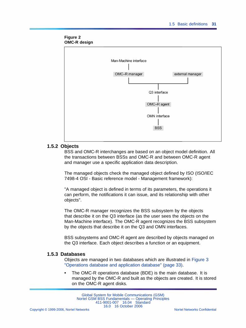
The OMC-R is a BSS subsystem manager that performs mediation functionsand provides a Q3 interface:
• The OMC-R manager enables exchanges with users through theMan-Machine interface, and with the OMC-R agent through the Q3interface.
• The OMC-R agent enables exchanges with the BSSs through the OMNinterface and provides mediation functions between managed objectson the Q3 interface and managed objects on the OMN interface.
The notifications are forwarded from the md to the local manager usinga pseudo Q3 interface. Whereas the notifications sent to the externalmanagers are correlated, those sent to the local manager are un-correlated.Thus the flood of notifications is faster for the local manager, whichever isthe response delay of the external managers.
Global System for Mobile Communications (GSM)Nortel GSM BSS Fundamentals — Operating Principles
411-9001-007 16.04 Standard16.0 16 October 2006
Copyright © 1999-2006, Nortel Networks Nortel Networks Confidential
.
1.5 Basic definitions 31
Figure 2OMC-R design
1.5.2 ObjectsBSS and OMC-R interchanges are based on an object model definition. Allthe transactions between BSSs and OMC-R and between OMC-R agentand manager use a specific application data description.
The managed objects check the managed object defined by ISO (ISO/IEC7498-4 OSI - Basic reference model - Management framework):
"A managed object is defined in terms of its parameters, the operations itcan perform, the notifications it can issue, and its relationship with otherobjects".
The OMC-R manager recognizes the BSS subsystem by the objectsthat describe it on the Q3 interface (as the user sees the objects on theMan-Machine interface). The OMC-R agent recognizes the BSS subsystemby the objects that describe it on the Q3 and OMN interfaces.
BSS subsystems and OMC-R agent are described by objects managed onthe Q3 interface. Each object describes a function or an equipment.
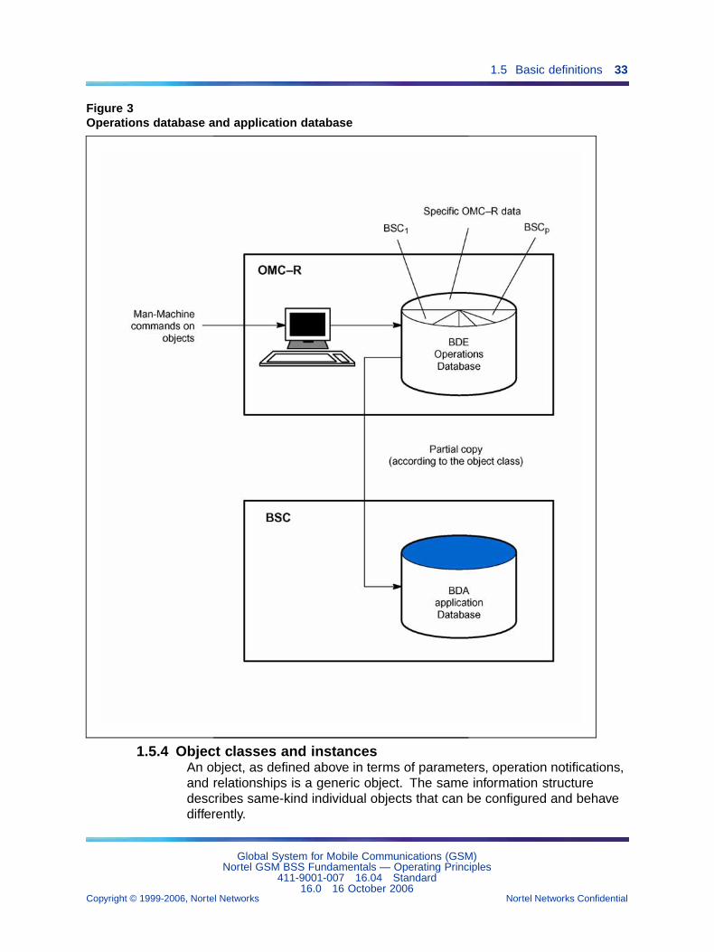
1.5.3 DatabasesObjects are managed in two databases which are illustrated in Figure 3"Operations database and application database" (page 33).
• The OMC-R operations database (BDE) is the main database. It ismanaged by the OMC-R and built as the objects are created. It is storedon the OMC-R agent disks.
Global System for Mobile Communications (GSM)Nortel GSM BSS Fundamentals — Operating Principles
411-9001-007 16.04 Standard16.0 16 October 2006
Copyright © 1999-2006, Nortel Networks Nortel Networks Confidential
.
32 Chapter 1 General operating mechanisms
The BDE is automatically updated after each operation and containsall the BSS objects, and certain specific OMC-R objects that are notknown to the BSC.
• The BSC application database (BDA) is stored on the BSC disk. It isbuilt from the BDE. The BSC database building operation is controlledby users.
To allow the system to function correctly, the two databases must beconsistent. Users can check their consistency by using an auditingcommand. The system warns the user if the two bases are inconsistent, bysending a specific message in response to the command.
Global System for Mobile Communications (GSM)Nortel GSM BSS Fundamentals — Operating Principles
411-9001-007 16.04 Standard16.0 16 October 2006
Copyright © 1999-2006, Nortel Networks Nortel Networks Confidential
.
1.5 Basic definitions 33
Figure 3Operations database and application database
1.5.4 Object classes and instancesAn object, as defined above in terms of parameters, operation notifications,and relationships is a generic object. The same information structuredescribes same-kind individual objects that can be configured and behavedifferently.
Global System for Mobile Communications (GSM)Nortel GSM BSS Fundamentals — Operating Principles
411-9001-007 16.04 Standard16.0 16 October 2006
Copyright © 1999-2006, Nortel Networks Nortel Networks Confidential
.
34 Chapter 1 General operating mechanisms
For example, the same information structure is used to describe all thebts objects modelling the radio cells under OMC-R management control.The description differentiates a non-operational cell C1 configured withtwo TRX/DRXs at a given time from an operational cell C2 configured withfour TRX/DRXs at the same time.
To avoid any ambiguity between the generic object and the individual object,a difference is made between the object class and the object instance. Inthe example above, C1 and C2 are both instances of the bts object class.
1.5.5 ParametersAll the objects in a same class are described in the same way by a set ofparameters. The values of these parameters vary according to the object.
There are three kinds of parameters:
• Permanent parameters, which are defined by the users
They are recorded in the BDE and BDA databases. Most of them aremandatory and are defined with the object that uses them. Some ofthem are optional and their value depends on the radio subsystemconfiguration. They are designated by the abbreviation DP (PermanentData) in this NTP.
• Dynamic parameters, which are not controlled by the users
They are not controlled by users. They are not recorded in thedatabases. The BSC manages dynamic parameters that are updated byBSC applications and can be consulted on request. They are designatedby the abbreviation DD (Dynamic Data) in this NTP.
• Internal parameters, which are managed from the OMC-R
They are recorded in the BDE database and cannot be modified byusers. They supply additional information on the object configuration ata given time and can be consulted on request. They are designated bythe abbreviation DI (Internal Data) in this NTP.
For more information on parameters:
• In alphabetical order, refer to NTP <124>.
• Grouped according to the objects, refer to NTP <128>.
1.5.6 OperationsOperations on objects are commands that the user sends to the OMC-Ron the Man-Machine interface. They allow users to communicate with theOMC-R and update the databases when necessary.
The OMC-R checks the command semantics before forwarding thecommands to the BSC to ensure that it only receives commands that arelikely to be correctly executed.
Global System for Mobile Communications (GSM)Nortel GSM BSS Fundamentals — Operating Principles
411-9001-007 16.04 Standard16.0 16 October 2006
Copyright © 1999-2006, Nortel Networks Nortel Networks Confidential
.
1.6 Configuration management 35
The same set of operations apply to all the objects in a given class. Themain types of operation are as follows:
• Create an object.
• Delete an object.
• Lock or unlock an object.
• Set an object’s permanent parameters.
• Display an object’s permanent and internal parameters.
• Display an object’s permanent, internal, and dynamic parameters.
• Audit a BDA to check consistency.
• Perform an action on an object.
1.5.7 Unsolicited messagesUnsolicited messages sent by the managed objects are translated intonotifications that provide users with information on network operatingconditions.
The same types of message apply to all the objects in a given class. Thesemessages are grouped as follows:
• software anomaly
• hardware fault
• warning
• state change
• parameter value change
• restart
• BIST result
• purge
• observation
• trace
• build BDA request
1.6 Configuration management1.6.1 Object classes
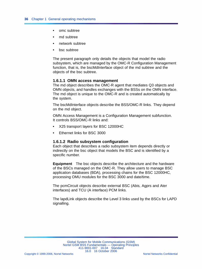
The system configuration is based on object class definitions. Figure 4"Object main tree structure" (page 37) to Figure 7 "Network subtree objects"(page 39) show the tree structure of the configuration objects managedon the OMC-R:
• main tree structure
Global System for Mobile Communications (GSM)Nortel GSM BSS Fundamentals — Operating Principles
411-9001-007 16.04 Standard16.0 16 October 2006
Copyright © 1999-2006, Nortel Networks Nortel Networks Confidential
.
36 Chapter 1 General operating mechanisms
• omc subtree
• md subtree
• network subtree
• bsc subtree
The present paragraph only details the objects that model the radiosubsystem, which are managed by the OMC-R Configuration Managementfunction, that is, the bscMdInterface object of the md subtree and theobjects of the bsc subtree.
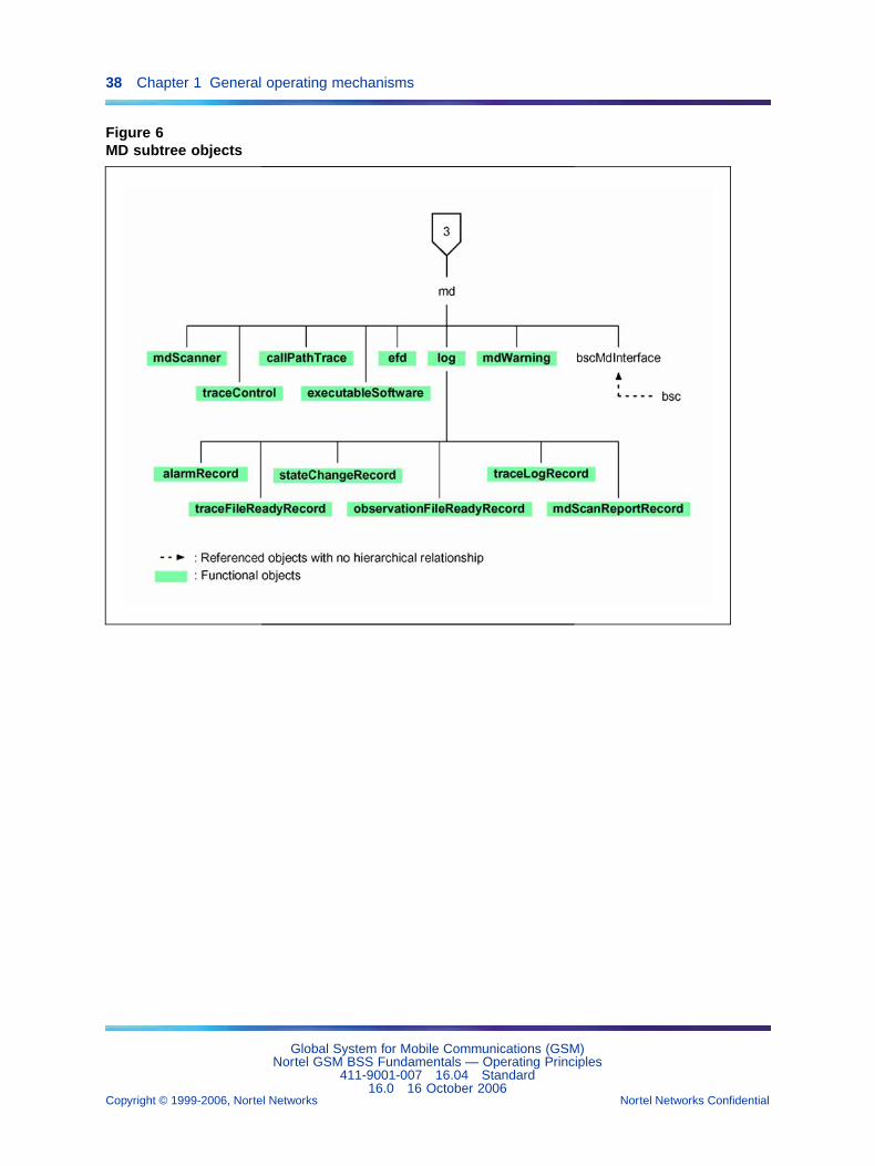
1.6.1.1 OMN access managementThe md object describes the OMC-R agent that mediates Q3 objects andOMN objects, and handles exchanges with the BSSs on the OMN interface.The md object is unique to the OMC-R and is created automatically bythe system.
The bscMdInterface objects describe the BSS/OMC-R links. They dependon the md object.
OMN Access Management is a Configuration Management subfunction.It controls BSS/OMC-R links and:
• X25 transport layers for BSC 12000HC
• Ethernet links for BSC 3000
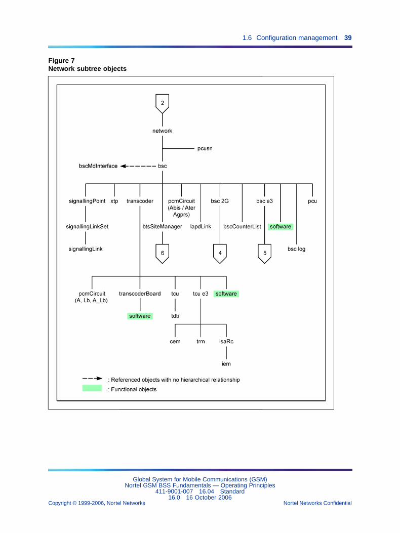
1.6.1.2 Radio subsystem configurationEach object that describes a radio subsystem item depends directly orindirectly on the bsc object that models the BSC and is identified by aspecific number.
Equipment The bsc objects describe the architecture and the hardwareof the BSCs managed on the OMC-R. They allow users to manage BSCapplication databases (BDA), processing chains for the BSC 12000HC,processing OMU modules for the BSC 3000 and date/time.
The pcmCircuit objects describe external BSC (Abis, Agprs and Aterinterfaces) and TCU (A interface) PCM links.
The lapdLink objects describe the Level 3 links used by the BSCs for LAPDsignalling.
Global System for Mobile Communications (GSM)Nortel GSM BSS Fundamentals — Operating Principles
411-9001-007 16.04 Standard16.0 16 October 2006
Copyright © 1999-2006, Nortel Networks Nortel Networks Confidential
.
1.6 Configuration management 37
Figure 4Object main tree structure
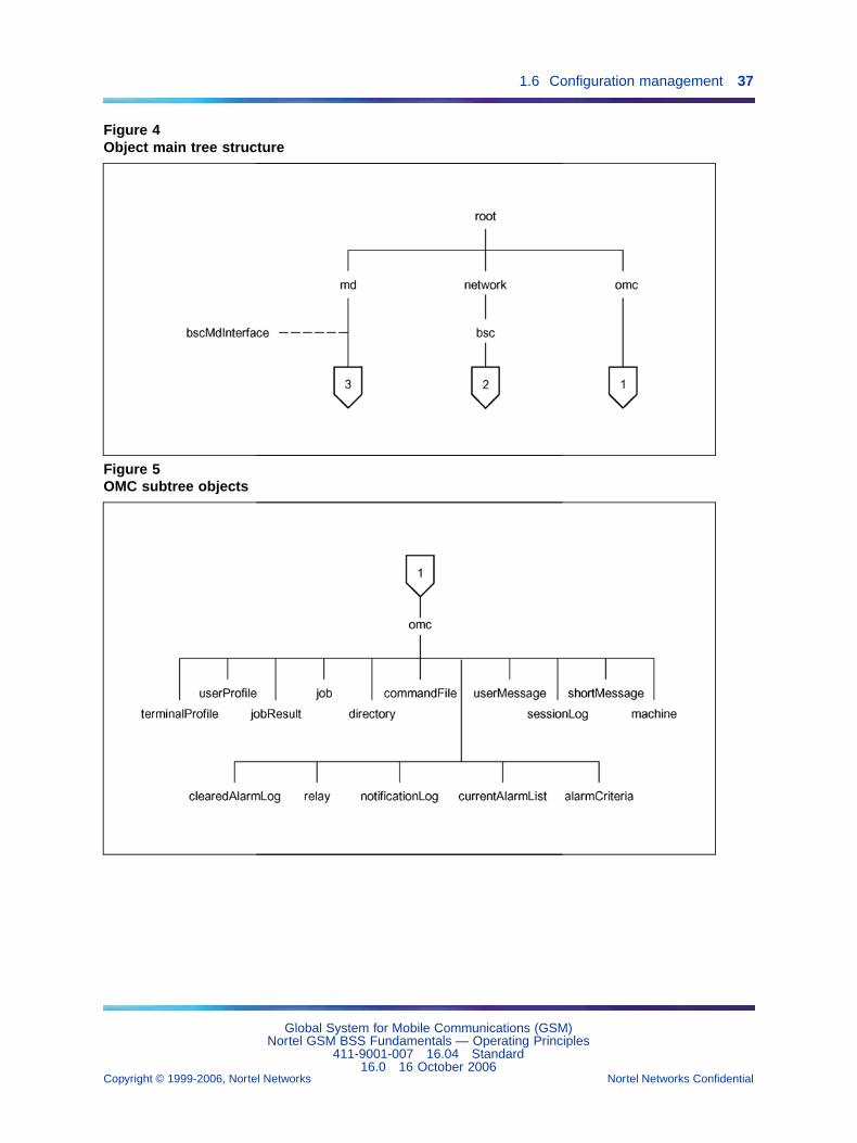
Figure 5OMC subtree objects
Global System for Mobile Communications (GSM)Nortel GSM BSS Fundamentals — Operating Principles
411-9001-007 16.04 Standard16.0 16 October 2006
Copyright © 1999-2006, Nortel Networks Nortel Networks Confidential
.
38 Chapter 1 General operating mechanisms
Figure 6MD subtree objects
Global System for Mobile Communications (GSM)Nortel GSM BSS Fundamentals — Operating Principles
411-9001-007 16.04 Standard16.0 16 October 2006
Copyright © 1999-2006, Nortel Networks Nortel Networks Confidential
.
1.6 Configuration management 39
Figure 7Network subtree objects
Global System for Mobile Communications (GSM)Nortel GSM BSS Fundamentals — Operating Principles
411-9001-007 16.04 Standard16.0 16 October 2006
Copyright © 1999-2006, Nortel Networks Nortel Networks Confidential
.
40 Chapter 1 General operating mechanisms
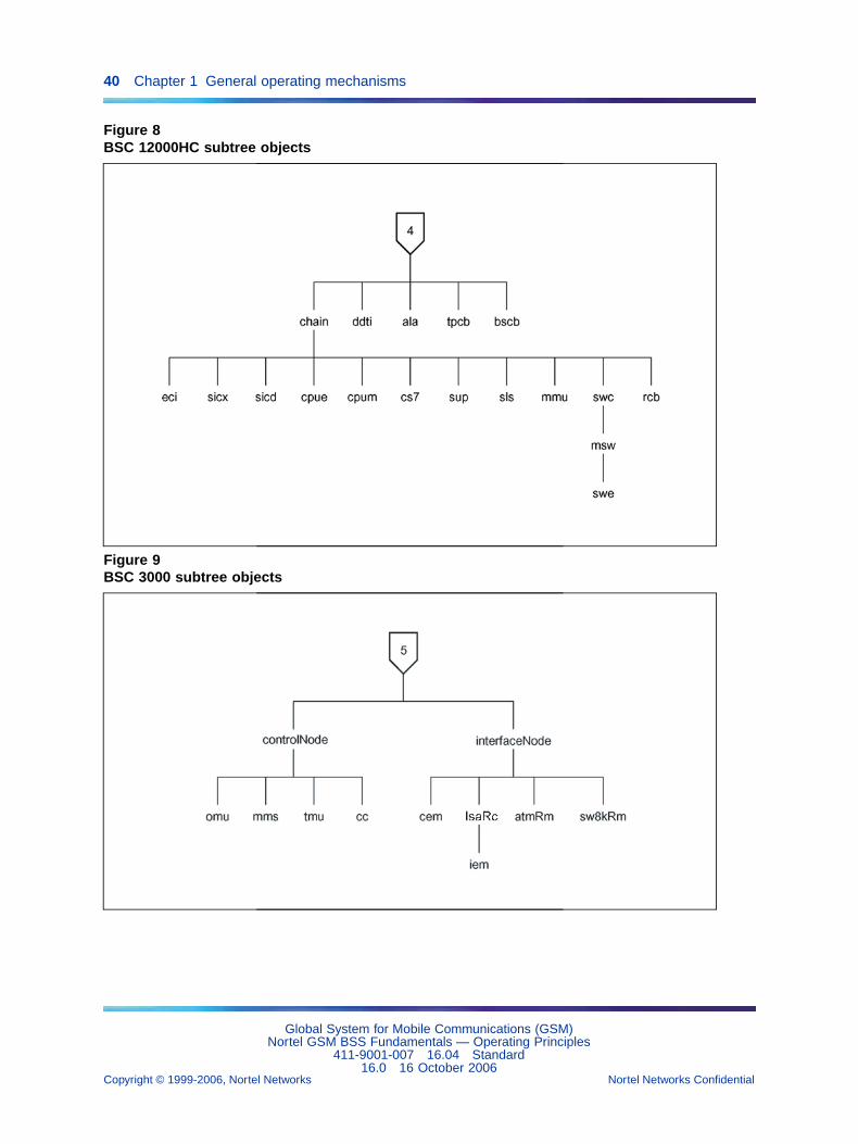
Figure 8BSC 12000HC subtree objects
Figure 9BSC 3000 subtree objects
Global System for Mobile Communications (GSM)Nortel GSM BSS Fundamentals — Operating Principles
411-9001-007 16.04 Standard16.0 16 October 2006
Copyright © 1999-2006, Nortel Networks Nortel Networks Confidential
.
1.6 Configuration management 41
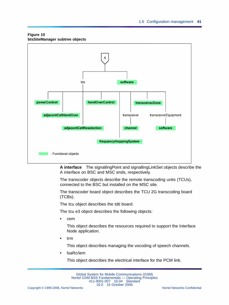
Figure 10btsSiteManager subtree objects
A interface The signallingPoint and signallingLinkSet objects describe theA interface on BSC and MSC ends, respectively.
The transcoder objects describe the remote transcoding units (TCUs),connected to the BSC but installed on the MSC site.
The transcoder board object describes the TCU 2G transcoding board(TCBs).
The tcu object describes the tdti board.
The tcu e3 object describes the following objects:
• cem
This object describes the resources required to support the InterfaceNode application.
• trm
This object describes managing the vocoding of speech channels.
• lsaRc/iem
This object describes the electrical interface for the PCM link.
Global System for Mobile Communications (GSM)Nortel GSM BSS Fundamentals — Operating Principles
411-9001-007 16.04 Standard16.0 16 October 2006
Copyright © 1999-2006, Nortel Networks Nortel Networks Confidential
.
42 Chapter 1 General operating mechanisms
The signallingLink objects describe the SS7 signalling links handled by theTCUs and used to convey signalling on the A interface.
The xtp objects describe the terrestrial traffic circuits handled by the TCUs,used to convey traffic and data on the A interface.
Radio and Abis resources The btsSiteManager objects describe radiosites (BTSs). BTS management on the Abis interface includes PCM links(level 1), LAPD protocol (level 2), and traffic and O&M signalling (level 3).
The bts objects describe the serving cells of radio sites.
The transceiverEquipment objects describe the transceiver units(TRX/DRXs) that manage TDMA frames in radio sites.
The transceiver objects describe TDMA frames (time-division multiplexingof radio channels) that enable radio transmissions.
The channel objects describe physical radio channels (TSs) in TDMAframes.
1.6.1.3 Software managementThe software-bsc objects allow users to download and start up BSCsoftware.
The software-btsSiteManager objects are used to download and start upBCF software.
The software-transceiverEquipment objects are used to download and startup TRX software.
The software transcoder board objects are used to download and startup TCB software.
The software bsc e3 and tcu e3 objects are downloaded to the BSC 3000disk. BSC 3000 is used to start up the TCU 3000 software.
Software Management is a Configuration Management subfunction thatdoes not depend on the radio subsystem configuration. Refer to Section1.10 "Software management" (page 91) for more details.
1.6.1.4 SMS-CB managementThe short message objects allow users to create short messages and tomanage unacknowledged message broadcasts in network radio cells.
Global System for Mobile Communications (GSM)Nortel GSM BSS Fundamentals — Operating Principles
411-9001-007 16.04 Standard16.0 16 October 2006
Copyright © 1999-2006, Nortel Networks Nortel Networks Confidential
.
1.6 Configuration management 43
SMS-CB management is a Configuration Management subfunction thatdoes not depend on the radio subsystem configuration. Refer to ParagraphSection 1.11 "SMS-CB management" (page 127) for more details.
1.6.2 Managed entitiesObject management entities are divided into the following subsets:
• managed object
• functional object
• Man Machine Interface (MMI) object
1.6.2.1 Managed object subsetA MANAGED OBJECT describes a graphic object, shown on theMan-Machine interface, that models a network element. A managed objectcan be directly accessed by users.
1.6.2.2 Functional object subsetA FUNCTIONAL OBJECT describes an object, which can be shown ornot shown on the Man-Machine interface (called a hidden object in casewhen it is not visible on the Man-Machine interface), that models a givenfunctionality.
A functional object relates to one managed object:
• The adjacentCellHandOver object associated with the bts objectdescribes the neighbor cells of serving cells for handover managementpurposes. It has numerous instances.
• The adjacentCellReselection object associated with the bts objectdescribes the BCCH frequencies used for reselection managementpurposes. It has numerous instances.
• The frequencyHoppingSystem object associated with the bts object(and related to the channel object) describes radio time slot frequencyhopping management parameters. It has numerous instances.
• The handOverControl object associated with the bts object describeshandover management parameters in serving cells. It has only oneinstance and must be created for each created bts object.
• The powerControl object associated with the bts object describespower control management parameters in serving cells. It has only oneinstance and must be created for each created bts object.
• The transceiverZone object associated with the bts object (and relatedto the transceiver object) describes TDMA frame allotment zones inconcentric serving cells. It has two instances and must be created foreach created bts object of this type.
Global System for Mobile Communications (GSM)Nortel GSM BSS Fundamentals — Operating Principles
411-9001-007 16.04 Standard16.0 16 October 2006
Copyright © 1999-2006, Nortel Networks Nortel Networks Confidential
.
44 Chapter 1 General operating mechanisms
• The software object associated with bsc, btsSiteManager,transceiverEquipment, transcoderBoard and tcu e3 objects, describesthe BSC, radio site BCF, TRX/DRX, TCB and TCU 3000 softwareversions, respectively. It has only one instance and must be created foreach created object in these classes.
Functional objects are managed by users as follows:
• A functional object is created after the managed object to which it refers.It can not be created unless required by the system configuration.
• A functional object instance is defined by the managed object instanceto which it refers and a specific identifier.
1.6.2.3 MMI object subsetAn MMI OBJECT is a non-Q3 object shown on the Man-Machine interface.MMI objects are managed by the OMC-R manager, they are not known bythe OMC-R agent and are not stored in its operations BDE database.
Two types of MMI OBJECT subsets are defined:
• The summary objects (See Figure 4 "Object main tree structure" (page37) to Figure 7 "Network subtree objects" (page 39)) represent sets ofobjects at higher level. They also summarize the real time informationon alarms available below on the corresponding objects.
• The omc object allows the user to manage the active alarm criteriaconfiguration, monitor OMC-R manager and connected workstationperformance, and initiate specific actions on the OMC-R manager.
1.6.3 State parametersThe managed objects have three ISO states:
• administrativeState
• operationalState
• availabilityStatus
1.6.3.1 AdministrativeStateThe administrative state is a permanent parameter [DP] with the followingvalues:
• unlocked
• locked
• shuttingDown (soft release of bts, transceiverEquipment and xtp objectsonly)
Global System for Mobile Communications (GSM)Nortel GSM BSS Fundamentals — Operating Principles
411-9001-007 16.04 Standard16.0 16 October 2006
Copyright © 1999-2006, Nortel Networks Nortel Networks Confidential
.
1.6 Configuration management 45
The OMC-R forces the administrativeState to "locked" when an object iscreated, except for the bscMdInterface objects that are created in unlockedstate. It can then be updated for users.
The administrativeState of certain objects is not significant:
• The bts, pcmCircuit, btsSiteManager, signallingLink, transceiverEquip-ment, transcoder, transcoderBoard, and xtp objects have anadministrativeState. Other objects cannot be brought to service untilthese objects are unlocked.
• The channel, lapdLink, signallingLinkSet, signallingPoint, and transceiverobjects have no administrativeState of their own (they are only significantto the OMC-R). The BSC manages their operationalState, whichdepends on the administrativeState of higher level objects.
• A functional object can have an administrativeState.
A managed object with no administrativeState of its own is automatically putinto service on the network.
The OMC-R manages the administrativeState of the bsc object as follows:
• The transition from unlocked to locked state has no impact on the BSC’sown operations.
• The transition from locked to unlocked state causes the automaticsuicide of both BSC processing chains if Class 1 parameters have beenmodified (BSC 12000HC only, see below).
1.6.3.2 OperationalStateThe operationalState of an object is a dynamic parameter [DD] that cannotbe modified by users. It can be displayed on the user’s request:
• enabled
• disabled
The operationalState of an object may be changed by internal systemoperating conditions, or when the administrativeState of the object oranother network object changes.
1.6.3.3 AvailabilityStatusThe availabilityStatus of an object is a dynamic parameter [DD] that cannotbe modified by the user.
Global System for Mobile Communications (GSM)Nortel GSM BSS Fundamentals — Operating Principles
411-9001-007 16.04 Standard16.0 16 October 2006
Copyright © 1999-2006, Nortel Networks Nortel Networks Confidential
.
46 Chapter 1 General operating mechanisms
It can be displayed on the user’s request:
{} ......................... not significant
dependency ........ out of reach
failed ................... faulty
The availabilityStatus of an object is specific to that object. It providesadditional information in association with other state parameters.
1.6.4 Managed object relationships1.6.4.1 Parent/child dependencyAn object A depends on an object B if A is out of reach when B is locked,and if when object B is unlocked, object A remains disabled until object Bis enabled.
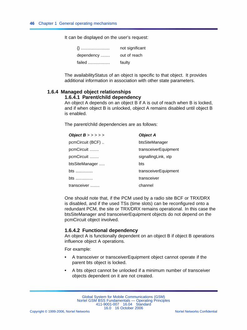
The parent/child dependencies are as follows:
Object B > > > > > Object A
pcmCircuit (BCF) .. btsSiteManager
pcmCircuit ........ transceiverEquipment
pcmCircuit ........ signallingLink, xtp
btsSiteManager ..... bts
bts ............... transceiverEquipment
bts ............... transceiver
transceiver ........ channel
One should note that, if the PCM used by a radio site BCF or TRX/DRXis disabled, and if the used TSs (time slots) can be reconfigured onto aredundant PCM, the site or TRX/DRX remains operational. In this case thebtsSiteManager and transceiverEquipment objects do not depend on thepcmCircuit object involved.
1.6.4.2 Functional dependencyAn object A is functionally dependent on an object B if object B operationsinfluence object A operations.
For example:
• A transceiver or transceiverEquipment object cannot operate if theparent bts object is locked.
• A bts object cannot be unlocked if a minimum number of transceiverobjects dependent on it are not created.
Global System for Mobile Communications (GSM)Nortel GSM BSS Fundamentals — Operating Principles
411-9001-007 16.04 Standard16.0 16 October 2006
Copyright © 1999-2006, Nortel Networks Nortel Networks Confidential
.
1.6 Configuration management 47
• A transceiver object cannot operate if the associatedtransceiverEquipment object is not operational.
The logical order to put objects into service is:
bts >>> transceiverEquipment >>> transceiver
A cell cannot operate if a minimum number of the TDMA frames dependingon it are not configured correctly (priority allocation) or if the TDMA frameconveying the BCCH is no longer operational.
1.6.4.3 Order of creating objectsThe order in which managed objects are created is determined by theirrelationships:
• A bsc object is the parent of a btsSiteManager object.
• A btsSiteManager object is the parent of a bts object.
• A bts object is the parent of a transceiverEquipment object.
• A bts object is the parent of a transceiver object.
• A transceiver object is the parent of a channel object.
• A bsc object is the parent of a pcu object.
Generally speaking, if an object B references an object A, object A mustbe created before object B.
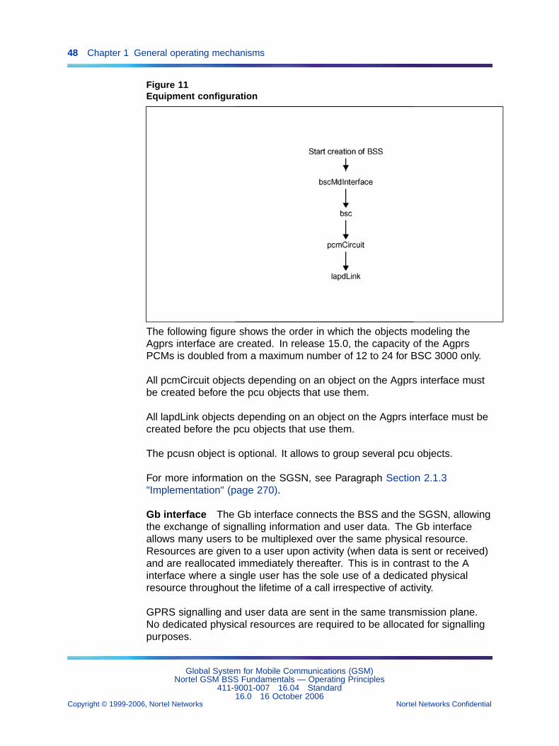
The following figure shows the order in which the objects modeling theequipment are created.
Global System for Mobile Communications (GSM)Nortel GSM BSS Fundamentals — Operating Principles
411-9001-007 16.04 Standard16.0 16 October 2006
Copyright © 1999-2006, Nortel Networks Nortel Networks Confidential
.
48 Chapter 1 General operating mechanisms
Figure 11Equipment configuration
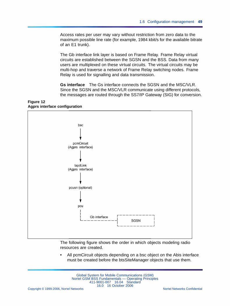
The following figure shows the order in which the objects modeling theAgprs interface are created. In release 15.0, the capacity of the AgprsPCMs is doubled from a maximum number of 12 to 24 for BSC 3000 only.
All pcmCircuit objects depending on an object on the Agprs interface mustbe created before the pcu objects that use them.
All lapdLink objects depending on an object on the Agprs interface must becreated before the pcu objects that use them.
The pcusn object is optional. It allows to group several pcu objects.
For more information on the SGSN, see Paragraph Section 2.1.3"Implementation" (page 270).
Gb interface The Gb interface connects the BSS and the SGSN, allowingthe exchange of signalling information and user data. The Gb interfaceallows many users to be multiplexed over the same physical resource.Resources are given to a user upon activity (when data is sent or received)and are reallocated immediately thereafter. This is in contrast to the Ainterface where a single user has the sole use of a dedicated physicalresource throughout the lifetime of a call irrespective of activity.
GPRS signalling and user data are sent in the same transmission plane.No dedicated physical resources are required to be allocated for signallingpurposes.
Global System for Mobile Communications (GSM)Nortel GSM BSS Fundamentals — Operating Principles
411-9001-007 16.04 Standard16.0 16 October 2006
Copyright © 1999-2006, Nortel Networks Nortel Networks Confidential
.
1.6 Configuration management 49
Access rates per user may vary without restriction from zero data to themaximum possible line rate (for example, 1984 kbit/s for the available bitrateof an E1 trunk).
The Gb interface link layer is based on Frame Relay. Frame Relay virtualcircuits are established between the SGSN and the BSS. Data from manyusers are multiplexed on these virtual circuits. The virtual circuits may bemulti-hop and traverse a network of Frame Relay switching nodes. FrameRelay is used for signalling and data transmission.
Gs interface The Gs interface connects the SGSN and the MSC/VLR.Since the SGSN and the MSC/VLR communicate using different protocols,the messages are routed through the SS7/IP Gateway (SIG) for conversion.
Figure 12Agprs interface configuration
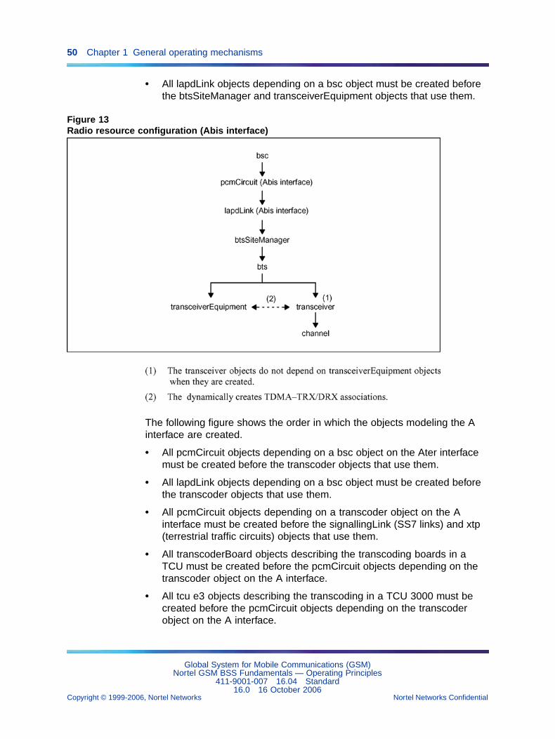
The following figure shows the order in which objects modeling radioresources are created.
• All pcmCircuit objects depending on a bsc object on the Abis interfacemust be created before the btsSiteManager objects that use them.
Global System for Mobile Communications (GSM)Nortel GSM BSS Fundamentals — Operating Principles
411-9001-007 16.04 Standard16.0 16 October 2006
Copyright © 1999-2006, Nortel Networks Nortel Networks Confidential
.
50 Chapter 1 General operating mechanisms
• All lapdLink objects depending on a bsc object must be created beforethe btsSiteManager and transceiverEquipment objects that use them.
Figure 13Radio resource configuration (Abis interface)
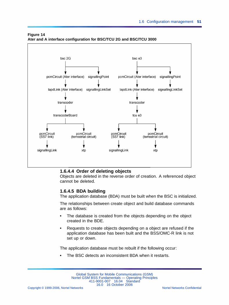
The following figure shows the order in which the objects modeling the Ainterface are created.
• All pcmCircuit objects depending on a bsc object on the Ater interfacemust be created before the transcoder objects that use them.
• All lapdLink objects depending on a bsc object must be created beforethe transcoder objects that use them.
• All pcmCircuit objects depending on a transcoder object on the Ainterface must be created before the signallingLink (SS7 links) and xtp(terrestrial traffic circuits) objects that use them.
• All transcoderBoard objects describing the transcoding boards in aTCU must be created before the pcmCircuit objects depending on thetranscoder object on the A interface.
• All tcu e3 objects describing the transcoding in a TCU 3000 must becreated before the pcmCircuit objects depending on the transcoderobject on the A interface.
Global System for Mobile Communications (GSM)Nortel GSM BSS Fundamentals — Operating Principles
411-9001-007 16.04 Standard16.0 16 October 2006
Copyright © 1999-2006, Nortel Networks Nortel Networks Confidential
.
1.6 Configuration management 51
Figure 14Ater and A interface configuration for BSC/TCU 2G and BSC/TCU 3000
1.6.4.4 Order of deleting objectsObjects are deleted in the reverse order of creation. A referenced objectcannot be deleted.
1.6.4.5 BDA buildingThe application database (BDA) must be built when the BSC is initialized.
The relationships between create object and build database commandsare as follows:
• The database is created from the objects depending on the objectcreated in the BDE.
• Requests to create objects depending on a object are refused if theapplication database has been built and the BSS/OMC-R link is notset up or down.
The application database must be rebuilt if the following occur:
• The BSC detects an inconsistent BDA when it restarts.
Global System for Mobile Communications (GSM)Nortel GSM BSS Fundamentals — Operating Principles
411-9001-007 16.04 Standard16.0 16 October 2006
Copyright © 1999-2006, Nortel Networks Nortel Networks Confidential
.
52 Chapter 1 General operating mechanisms
• BDA prototype configuration files are modified when the softwareversion is changed.
• The architecture or type of the object changes (class 0 parameters).
Only OMC-R class 0 is available for BDA.
• The result of the audit command indicates BDA inconsistencies.
• The system returns a software anomaly notification or an error messagein response to a user command.
In all cases, the database must be reset before rebuilding.
The database must also be rebuilt after an On line reset BDA command isused to reconfigure the network without influencing BSC operations.
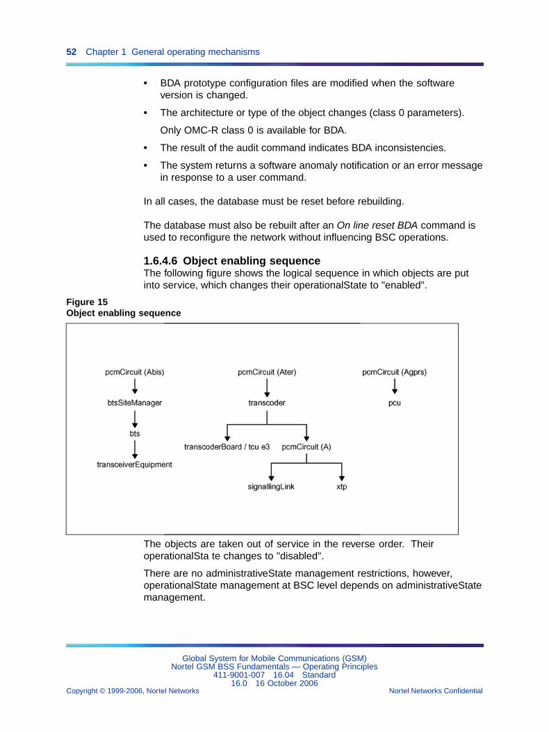
1.6.4.6 Object enabling sequenceThe following figure shows the logical sequence in which objects are putinto service, which changes their operationalState to "enabled".
Figure 15Object enabling sequence
The objects are taken out of service in the reverse order. TheiroperationalSta te changes to "disabled".
There are no administrativeState management restrictions, however,operationalState management at BSC level depends on administrativeStatemanagement.
Global System for Mobile Communications (GSM)Nortel GSM BSS Fundamentals — Operating Principles
411-9001-007 16.04 Standard16.0 16 October 2006
Copyright © 1999-2006, Nortel Networks Nortel Networks Confidential
.
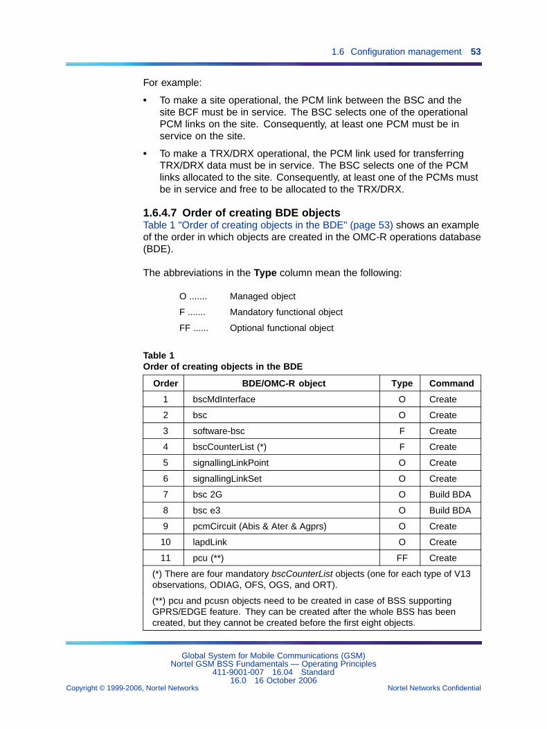
1.6 Configuration management 53
For example:
• To make a site operational, the PCM link between the BSC and thesite BCF must be in service. The BSC selects one of the operationalPCM links on the site. Consequently, at least one PCM must be inservice on the site.
• To make a TRX/DRX operational, the PCM link used for transferringTRX/DRX data must be in service. The BSC selects one of the PCMlinks allocated to the site. Consequently, at least one of the PCMs mustbe in service and free to be allocated to the TRX/DRX.
1.6.4.7 Order of creating BDE objectsTable 1 "Order of creating objects in the BDE" (page 53) shows an exampleof the order in which objects are created in the OMC-R operations database(BDE).
The abbreviations in the Type column mean the following:
O ....... Managed object
F ....... Mandatory functional object
FF ...... Optional functional object
Table 1Order of creating objects in the BDE
Order BDE/OMC-R object Type Command
1 bscMdInterface O Create
2 bsc O Create
3 software-bsc F Create
4 bscCounterList (*) F Create
5 signallingLinkPoint O Create
6 signallingLinkSet O Create
7 bsc 2G O Build BDA
8 bsc e3 O Build BDA
9 pcmCircuit (Abis & Ater & Agprs) O Create
10 lapdLink O Create
11 pcu (**) FF Create
(*) There are four mandatory bscCounterList objects (one for each type of V13observations, ODIAG, OFS, OGS, and ORT).
(**) pcu and pcusn objects need to be created in case of BSS supportingGPRS/EDGE feature. They can be created after the whole BSS has beencreated, but they cannot be created before the first eight objects.
Global System for Mobile Communications (GSM)Nortel GSM BSS Fundamentals — Operating Principles
411-9001-007 16.04 Standard16.0 16 October 2006
Copyright © 1999-2006, Nortel Networks Nortel Networks Confidential
.
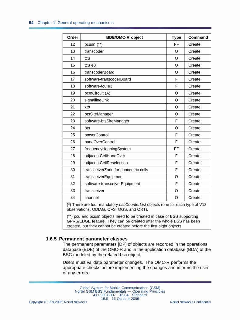
54 Chapter 1 General operating mechanisms
Order BDE/OMC-R object Type Command
12 pcusn (**) FF Create
13 transcoder O Create
14 tcu O Create
15 tcu e3 O Create
16 transcoderBoard O Create
17 software-transcoderBoard F Create
18 software-tcu e3 F Create
19 pcmCircuit (A) O Create
20 signallingLink O Create
21 xtp O Create
22 btsSiteManager O Create
23 software-btsSiteManager F Create
24 bts O Create
25 powerControl F Create
26 handOverControl F Create
27 frequencyHoppingSystem FF Create
28 adjacentCellHandOver F Create
29 adjacentCellReselection F Create
30 transceiverZone for concentric cells F Create
31 transceiverEquipment O Create
32 software-transceiverEquipment F Create
33 transceiver O Create
34 channel O Create
(*) There are four mandatory bscCounterList objects (one for each type of V13observations, ODIAG, OFS, OGS, and ORT).
(**) pcu and pcusn objects need to be created in case of BSS supportingGPRS/EDGE feature. They can be created after the whole BSS has beencreated, but they cannot be created before the first eight objects.
1.6.5 Permanent parameter classesThe permanent parameters [DP] of objects are recorded in the operationsdatabase (BDE) of the OMC-R and in the application database (BDA) of theBSC modeled by the related bsc object.
Users must validate parameter changes. The OMC-R performs theappropriate checks before implementing the changes and informs the userof any errors.
Global System for Mobile Communications (GSM)Nortel GSM BSS Fundamentals — Operating Principles
411-9001-007 16.04 Standard16.0 16 October 2006
Copyright © 1999-2006, Nortel Networks Nortel Networks Confidential
.
1.6 Configuration management 55
The system is not always reconfigured immediately after the parametersare set. The impact of the changes on other objects or BSC operatingconditions is determined. For this reason, permanent parameters areorganized in classes. The classes are as follows:
• Class 0 parameters
• Class 1 parameters
• Class 2 parameters
• Class 3 parameters
1.6.5.1 Class 0 parametersThe class 0 parameters are as follows:
• The OMC-R manages class 0 parameter changes (no transaction issent to the BSC). Class 0 parameters can only be set before the BSCapplication database (BDA) is built (bdaState = "not built").
• The system is effectively reconfigured after the BSC database is built inresponse to a Build BDA command.
• Class 0 is the most restrictive class.
1.6.5.2 Class 1 parameters for BSC 12000HC onlyThe class 1 parameters are as follows:
• The class 1 parameters of an object created on the OMC-R can onlybe set when the related bsc object is locked.
• In this mode, the modeled BSC remains operational, but the systemonly accepts commands that modify the class 1 parameters of the bscor dependent objects, and the following commands:
— On line and Off line reset BDA commands on the bsc object
— Kill chain and Suicide chain commands on the bsc 12000HC object
— Kill cn/in and Suicide cn/in commands on the bsc e3 object
— change software version commands (see Section 1.10 "Softwaremanagement" (page 91))
• The system is effectively reconfigured after the bsc object is unlocked.Both BSC 12000HC processing chains are reset when class 1parameters are effectively modified.
1.6.5.3 Class 2 parametersThe class 2 parameters are as follows:
• The class 2 parameters of an object created on the OMC-R can only beset when the object is locked and the parent bsc object is unlocked.
Global System for Mobile Communications (GSM)Nortel GSM BSS Fundamentals — Operating Principles
411-9001-007 16.04 Standard16.0 16 October 2006
Copyright © 1999-2006, Nortel Networks Nortel Networks Confidential
.
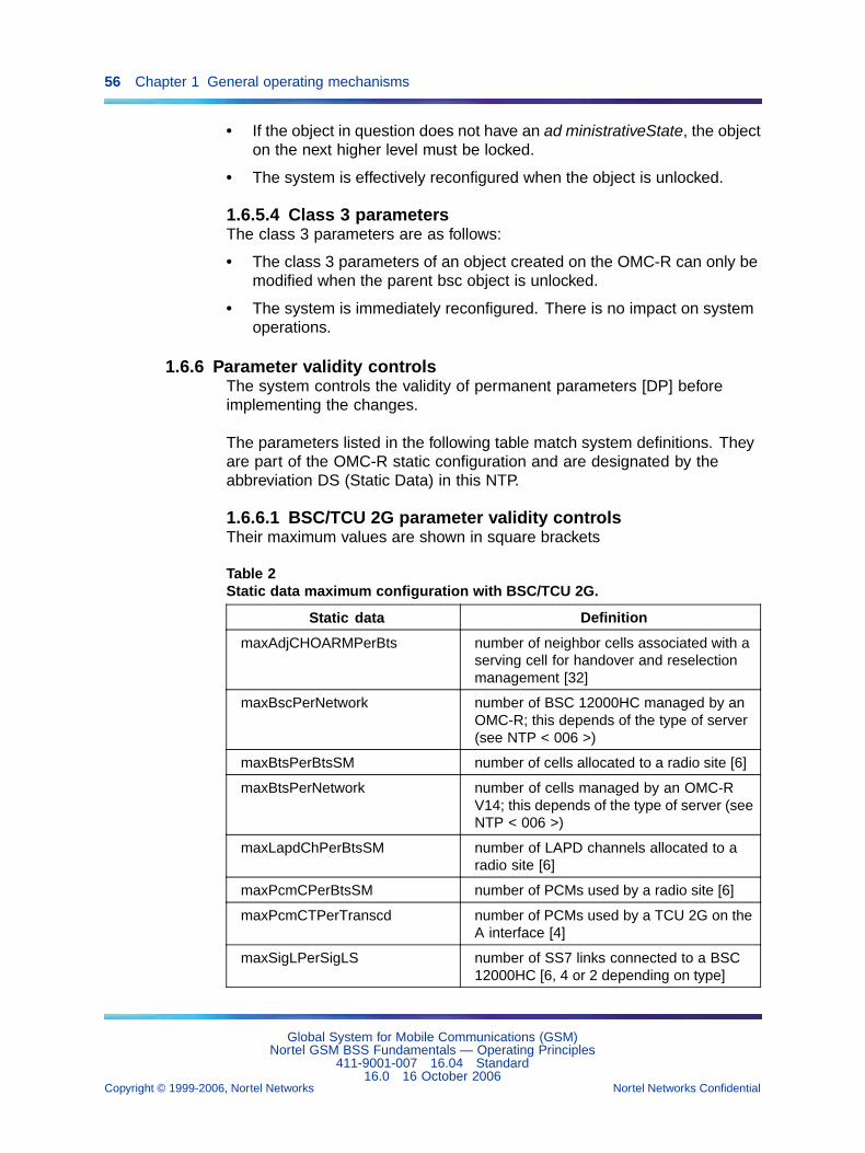
56 Chapter 1 General operating mechanisms
• If the object in question does not have an ad ministrativeState, the objecton the next higher level must be locked.
• The system is effectively reconfigured when the object is unlocked.
1.6.5.4 Class 3 parametersThe class 3 parameters are as follows:
• The class 3 parameters of an object created on the OMC-R can only bemodified when the parent bsc object is unlocked.
• The system is immediately reconfigured. There is no impact on systemoperations.
1.6.6 Parameter validity controlsThe system controls the validity of permanent parameters [DP] beforeimplementing the changes.
The parameters listed in the following table match system definitions. Theyare part of the OMC-R static configuration and are designated by theabbreviation DS (Static Data) in this NTP.
1.6.6.1 BSC/TCU 2G parameter validity controlsTheir maximum values are shown in square brackets
Table 2Static data maximum configuration with BSC/TCU 2G.
Static data Definition
maxAdjCHOARMPerBts number of neighbor cells associated with aserving cell for handover and reselectionmanagement [32]
maxBscPerNetwork number of BSC 12000HC managed by anOMC-R; this depends of the type of server(see NTP < 006 >)
maxBtsPerBtsSM number of cells allocated to a radio site [6]
maxBtsPerNetwork number of cells managed by an OMC-RV14; this depends of the type of server (seeNTP < 006 >)
maxLapdChPerBtsSM number of LAPD channels allocated to aradio site [6]
maxPcmCPerBtsSM number of PCMs used by a radio site [6]
maxPcmCTPerTranscd number of PCMs used by a TCU 2G on theA interface [4]
maxSigLPerSigLS number of SS7 links connected to a BSC12000HC [6, 4 or 2 depending on type]
Global System for Mobile Communications (GSM)Nortel GSM BSS Fundamentals — Operating Principles
411-9001-007 16.04 Standard16.0 16 October 2006
Copyright © 1999-2006, Nortel Networks Nortel Networks Confidential
.
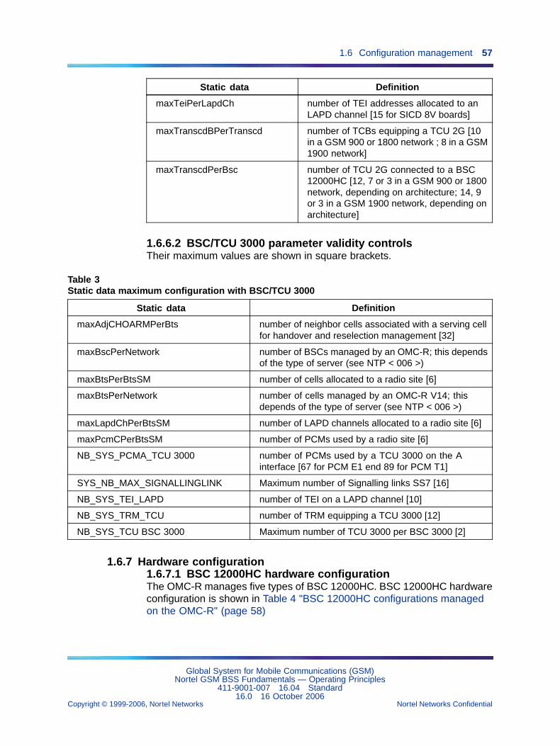
1.6 Configuration management 57
Static data Definition
maxTeiPerLapdCh number of TEI addresses allocated to anLAPD channel [15 for SICD 8V boards]
maxTranscdBPerTranscd number of TCBs equipping a TCU 2G [10in a GSM 900 or 1800 network ; 8 in a GSM1900 network]
maxTranscdPerBsc number of TCU 2G connected to a BSC12000HC [12, 7 or 3 in a GSM 900 or 1800network, depending on architecture; 14, 9or 3 in a GSM 1900 network, depending onarchitecture]
1.6.6.2 BSC/TCU 3000 parameter validity controlsTheir maximum values are shown in square brackets.
Table 3Static data maximum configuration with BSC/TCU 3000
Static data Definition
maxAdjCHOARMPerBts number of neighbor cells associated with a serving cellfor handover and reselection management [32]
maxBscPerNetwork number of BSCs managed by an OMC-R; this dependsof the type of server (see NTP < 006 >)
maxBtsPerBtsSM number of cells allocated to a radio site [6]
maxBtsPerNetwork number of cells managed by an OMC-R V14; thisdepends of the type of server (see NTP < 006 >)
maxLapdChPerBtsSM number of LAPD channels allocated to a radio site [6]
maxPcmCPerBtsSM number of PCMs used by a radio site [6]
NB_SYS_PCMA_TCU 3000 number of PCMs used by a TCU 3000 on the Ainterface [67 for PCM E1 end 89 for PCM T1]
SYS_NB_MAX_SIGNALLINGLINK Maximum number of Signalling links SS7 [16]
NB_SYS_TEI_LAPD number of TEI on a LAPD channel [10]
NB_SYS_TRM_TCU number of TRM equipping a TCU 3000 [12]
NB_SYS_TCU BSC 3000 Maximum number of TCU 3000 per BSC 3000 [2]
1.6.7 Hardware configuration1.6.7.1 BSC 12000HC hardware configurationThe OMC-R manages five types of BSC 12000HC. BSC 12000HC hardwareconfiguration is shown in Table 4 "BSC 12000HC configurations managedon the OMC-R" (page 58)
Global System for Mobile Communications (GSM)Nortel GSM BSS Fundamentals — Operating Principles
411-9001-007 16.04 Standard16.0 16 October 2006
Copyright © 1999-2006, Nortel Networks Nortel Networks Confidential
.
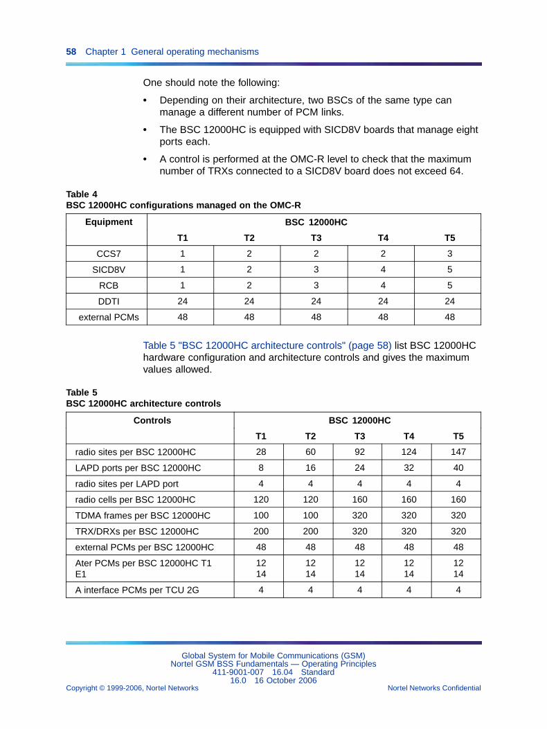
58 Chapter 1 General operating mechanisms
One should note the following:
• Depending on their architecture, two BSCs of the same type canmanage a different number of PCM links.
• The BSC 12000HC is equipped with SICD8V boards that manage eightports each.
• A control is performed at the OMC-R level to check that the maximumnumber of TRXs connected to a SICD8V board does not exceed 64.
Table 4BSC 12000HC configurations managed on the OMC-R
BSC 12000HCEquipment
T1 T2 T3 T4 T5
CCS7 1 2 2 2 3
SICD8V 1 2 3 4 5
RCB 1 2 3 4 5
DDTI 24 24 24 24 24
external PCMs 48 48 48 48 48
Table 5 "BSC 12000HC architecture controls" (page 58) list BSC 12000HChardware configuration and architecture controls and gives the maximumvalues allowed.
Table 5BSC 12000HC architecture controls
BSC 12000HCControls
T1 T2 T3 T4 T5
radio sites per BSC 12000HC 28 60 92 124 147
LAPD ports per BSC 12000HC 8 16 24 32 40
radio sites per LAPD port 4 4 4 4 4
radio cells per BSC 12000HC 120 120 160 160 160
TDMA frames per BSC 12000HC 100 100 320 320 320
TRX/DRXs per BSC 12000HC 200 200 320 320 320
external PCMs per BSC 12000HC 48 48 48 48 48
Ater PCMs per BSC 12000HC T1E1
1214
1214
1214
1214
1214
A interface PCMs per TCU 2G 4 4 4 4 4
Global System for Mobile Communications (GSM)Nortel GSM BSS Fundamentals — Operating Principles
411-9001-007 16.04 Standard16.0 16 October 2006
Copyright © 1999-2006, Nortel Networks Nortel Networks Confidential
.
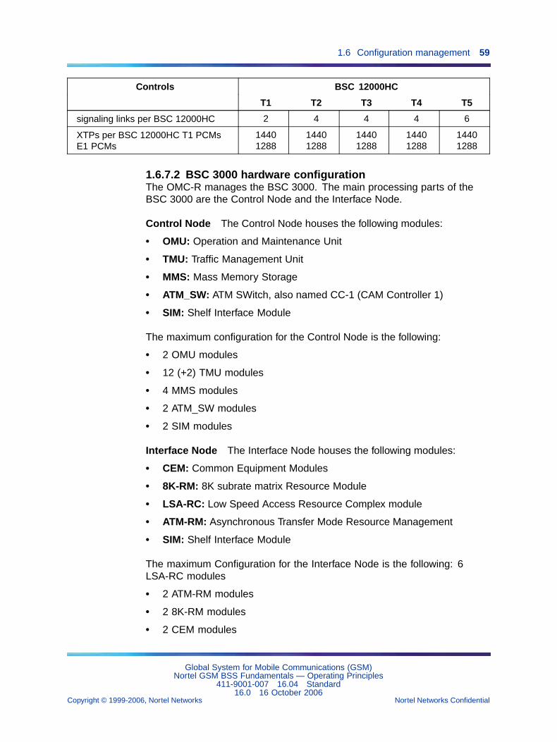
1.6 Configuration management 59
BSC 12000HCControls
T1 T2 T3 T4 T5
signaling links per BSC 12000HC 2 4 4 4 6
XTPs per BSC 12000HC T1 PCMsE1 PCMs
14401288
14401288
14401288
14401288
14401288
1.6.7.2 BSC 3000 hardware configurationThe OMC-R manages the BSC 3000. The main processing parts of theBSC 3000 are the Control Node and the Interface Node.
Control Node The Control Node houses the following modules:
• OMU: Operation and Maintenance Unit
• TMU: Traffic Management Unit
• MMS: Mass Memory Storage
• ATM_SW: ATM SWitch, also named CC-1 (CAM Controller 1)
• SIM: Shelf Interface Module
The maximum configuration for the Control Node is the following:
• 2 OMU modules
• 12 (+2) TMU modules
• 4 MMS modules
• 2 ATM_SW modules
• 2 SIM modules
Interface Node The Interface Node houses the following modules:
• CEM: Common Equipment Modules
• 8K-RM: 8K subrate matrix Resource Module
• LSA-RC: Low Speed Access Resource Complex module
• ATM-RM: Asynchronous Transfer Mode Resource Management
• SIM: Shelf Interface Module
The maximum Configuration for the Interface Node is the following: 6LSA-RC modules
• 2 ATM-RM modules
• 2 8K-RM modules
• 2 CEM modules
Global System for Mobile Communications (GSM)Nortel GSM BSS Fundamentals — Operating Principles
411-9001-007 16.04 Standard16.0 16 October 2006
Copyright © 1999-2006, Nortel Networks Nortel Networks Confidential
.
60 Chapter 1 General operating mechanisms
• 2 SIM modules
For more information about the BSC 3000 architecture refer to the NTP< 126 >.
1.6.8 BSC 3000 load balancing - estimatedSiteLoad parameterThe "BSC 3000 load balancing - estimatedSiteLoad parameter" feature(24520), introduced in V15.1, enables the operator to specify the estimatedErlang load of a cell group using the estimatedSiteLoad parameter andprovides an improved load distribution function.
1.6.8.1 Erlang load of a cell groupAn Erlang is a unit of measure of telecommunications traffic load/intensity.Capacity can also be expressed in Erlangs (since capacity is the capabilityto handle a given traffic load). Since handling traffic involves consumingresources, there is also a relationship between traffic load (in Erlangs) andresource consumption. For example, a high Erlang value results in a greaterconsumption of CPU and memory resources than a low Erlang value.
Pre-V15.1, the Erlang load of a cell group was calculated from a MIB table"Erlang_Per_N_TRX_Cell". This table can be modified using the BSC DataConfiguration procedure (see the description of this procedure in NTP<034>).
With the feature 24520, the operator can also specify the Erlang load ofa cell group using the estimatedSiteLoad parameter which is then usedinstead of the value in the MIB table. If the estimatedSiteLoad is notspecified or is set to 0, the value in the MIB table is still used.
1.6.8.2 Load distributionThe BSC 3000 Load Balancing function distributes the load among theTMUs (Traffic Management Units) that are available.
If the traffic load is modified, the Load Balancing function adjusts thisdistribution. Examples of events that modify the traffic load include: cellreconfiguration, addition of TRX, addition of a cell/site/cell group, additionof TCU, change of TCU/PCU configuration, etc.
The Load Balancing function also adjusts the load distribution if the offeredcapacity is modified. Examples of events that modify the offered capacityinclude: addition of a TMU, failure/recovery of a TMU, and removal of a TMU.
Each time the Load Balancing function adjusts the load distribution, it sendsa notification (ANO_LB_RESULT) to the OMC-R.
Global System for Mobile Communications (GSM)Nortel GSM BSS Fundamentals — Operating Principles
411-9001-007 16.04 Standard16.0 16 October 2006
Copyright © 1999-2006, Nortel Networks Nortel Networks Confidential
.
1.6 Configuration management 61
1.6.8.3 Anomaly detected during load distributionThe BSC 3000 Load Balancing function compares the number of TMUsavailable with the number of TMUs required to reach the capacity configuredby the OMC (in terms of sites, cells, TRXs, TCUs, PCUs, etc.).
If the Load Balancing function concludes that there are not enough TMUsavailable, it notifies the OMC (alarm ANO_LOADBALANCING) and indicatesthe number of extra TMUs needed (to reach the required capacity).
The parameters estimatedSiteLoad, associatedTMUPosition, cpueNumber,and cpueOccurence are associated with this feature. See also thedescriptions of these parameters in NTP <124>.
1.6.9 Number radio site configuration1.6.9.1 BSC 12000HC number radio siteThe number of radio sites controlled by a BSC 12000HC is calculated asfollows:
• When a BSC 12000HC does not concentrate BTS LAPD signaling, themaximum number of sites managed by the BSC 12000HC is less thanthe number of available SICD ports: one port is reserved for the remotetranscoders and each site uses one SICD port.
• When a BSC 12000HC concentrates BTS LAPD signaling, it is equippedwith twelve BSCBs. Since each BSCB concentrates the signaling oftwelve radio sites on three LAPD links (four sites per link) and eachLAPD link uses one SICD port, the following apply:
— Twelve BSCBs handle 12x12 = 144 sites.
— Twelve BSCBs use 3x12 = 36 SICD ports.
Since the BSC 12000HC is equipped with forty SICD ports among whichone is reserved for TCU signaling, three more can be allotted to threeindividual sites, which gives a total of 144 + 3 = 147 radio sites.
If one of the BSCBs is used for redundancy (default configuration), theconcentration is performed by eleven BSCBs (that is 132 sites) whichuse thirty-three SICD ports. Six SICD ports can then be allotted to sixindividual sites (40 - 33 - 1), which gives a total of 132 + 6 = 138 radiosites.
For BSC 12000HC types 1, 2, 3, and 4, the number of sites controlledby the BSC 12000HC is limited by the number of SICD ports available;one port is reserved for remote transcoders and any other SICD portcan be used for four concentrated sites signaling.
Global System for Mobile Communications (GSM)Nortel GSM BSS Fundamentals — Operating Principles
411-9001-007 16.04 Standard16.0 16 October 2006
Copyright © 1999-2006, Nortel Networks Nortel Networks Confidential
.
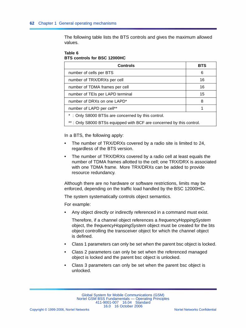
62 Chapter 1 General operating mechanisms
The following table lists the BTS controls and gives the maximum allowedvalues.
Table 6BTS controls for BSC 12000HC
Controls BTS
number of cells per BTS 6
number of TRX/DRXs per cell 16
number of TDMA frames per cell 16
number of TEIs per LAPD terminal 15
number of DRXs on one LAPD* 8
number of LAPD per cell** 1
* : Only S8000 BTSs are concerned by this control.
** : Only S8000 BTSs equipped with BCF are concerned by this control.
In a BTS, the following apply:
• The number of TRX/DRXs covered by a radio site is limited to 24,regardless of the BTS version.
• The number of TRX/DRXs covered by a radio cell at least equals thenumber of TDMA frames allotted to the cell; one TRX/DRX is associatedwith one TDMA frame. More TRX/DRXs can be added to provideresource redundancy.
Although there are no hardware or software restrictions, limits may beenforced, depending on the traffic load handled by the BSC 12000HC.
The system systematically controls object semantics.
For example:
• Any object directly or indirectly referenced in a command must exist.
Therefore, if a channel object references a frequencyHoppingSystemobject, the frequencyHoppingSystem object must be created for the btsobject controlling the transceiver object for which the channel objectis defined.
• Class 1 parameters can only be set when the parent bsc object is locked.
• Class 2 parameters can only be set when the referenced managedobject is locked and the parent bsc object is unlocked.
• Class 3 parameters can only be set when the parent bsc object isunlocked.
Global System for Mobile Communications (GSM)Nortel GSM BSS Fundamentals — Operating Principles
411-9001-007 16.04 Standard16.0 16 October 2006
Copyright © 1999-2006, Nortel Networks Nortel Networks Confidential
.
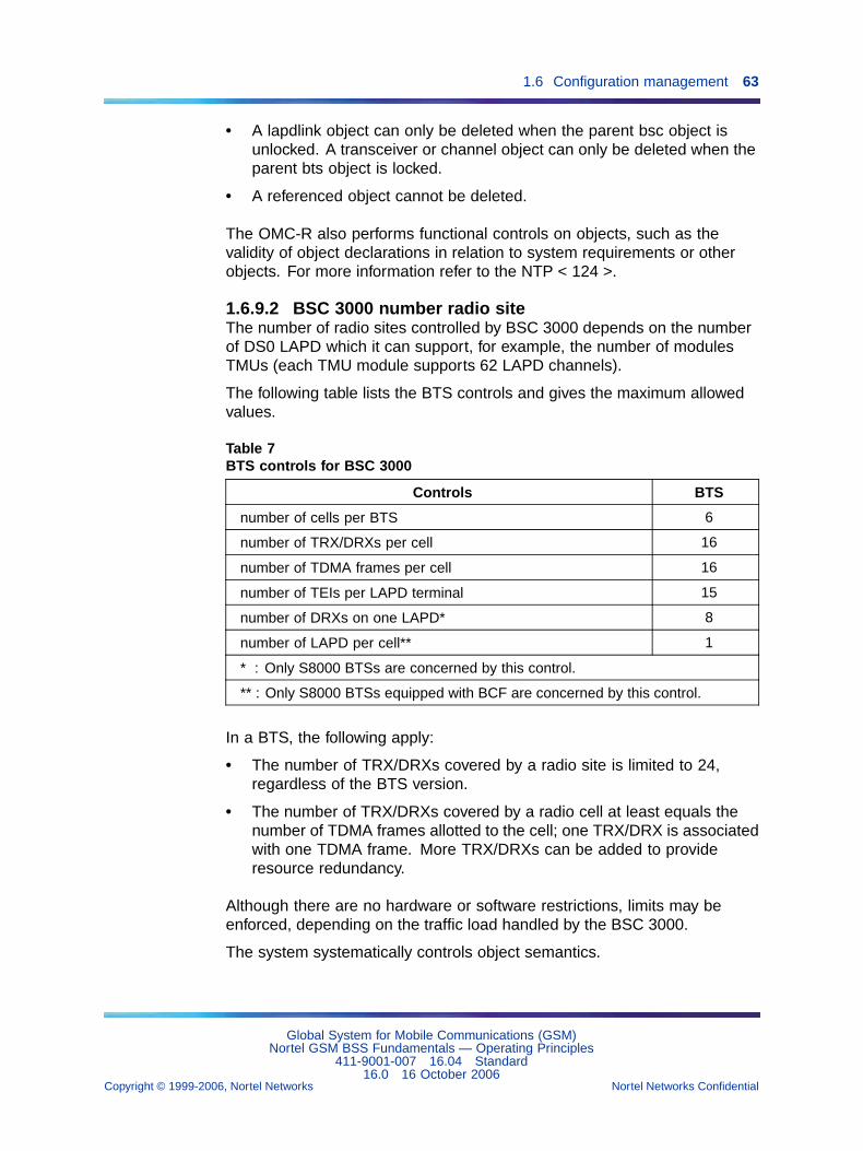
1.6 Configuration management 63
• A lapdlink object can only be deleted when the parent bsc object isunlocked. A transceiver or channel object can only be deleted when theparent bts object is locked.
• A referenced object cannot be deleted.
The OMC-R also performs functional controls on objects, such as thevalidity of object declarations in relation to system requirements or otherobjects. For more information refer to the NTP < 124 >.
1.6.9.2 BSC 3000 number radio siteThe number of radio sites controlled by BSC 3000 depends on the numberof DS0 LAPD which it can support, for example, the number of modulesTMUs (each TMU module supports 62 LAPD channels).
The following table lists the BTS controls and gives the maximum allowedvalues.
Table 7BTS controls for BSC 3000
Controls BTS
number of cells per BTS 6
number of TRX/DRXs per cell 16
number of TDMA frames per cell 16
number of TEIs per LAPD terminal 15
number of DRXs on one LAPD* 8
number of LAPD per cell** 1
* : Only S8000 BTSs are concerned by this control.
** : Only S8000 BTSs equipped with BCF are concerned by this control.
In a BTS, the following apply:
• The number of TRX/DRXs covered by a radio site is limited to 24,regardless of the BTS version.
• The number of TRX/DRXs covered by a radio cell at least equals thenumber of TDMA frames allotted to the cell; one TRX/DRX is associatedwith one TDMA frame. More TRX/DRXs can be added to provideresource redundancy.
Although there are no hardware or software restrictions, limits may beenforced, depending on the traffic load handled by the BSC 3000.
The system systematically controls object semantics.
Global System for Mobile Communications (GSM)Nortel GSM BSS Fundamentals — Operating Principles
411-9001-007 16.04 Standard16.0 16 October 2006
Copyright © 1999-2006, Nortel Networks Nortel Networks Confidential
.
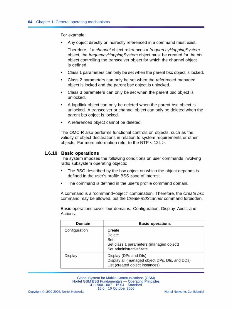
64 Chapter 1 General operating mechanisms
For example:
• Any object directly or indirectly referenced in a command must exist.
Therefore, if a channel object references a frequen cyHoppingSystemobject, the frequencyHoppingSystem object must be created for the btsobject controlling the transceiver object for which the channel objectis defined.
• Class 1 parameters can only be set when the parent bsc object is locked.
• Class 2 parameters can only be set when the referenced managedobject is locked and the parent bsc object is unlocked.
• Class 3 parameters can only be set when the parent bsc object isunlocked.
• A lapdlink object can only be deleted when the parent bsc object isunlocked. A transceiver or channel object can only be deleted when theparent bts object is locked.
• A referenced object cannot be deleted.
The OMC-R also performs functional controls on objects, such as thevalidity of object declarations in relation to system requirements or otherobjects. For more information refer to the NTP < 124 >.
1.6.10 Basic operationsThe system imposes the following conditions on user commands involvingradio subsystem operating objects:
• The BSC described by the bsc object on which the object depends isdefined in the user’s profile BSS zone of interest.
• The command is defined in the user’s profile command domain.
A command is a "command+object" combination. Therefore, the Create bsccommand may be allowed, but the Create mdScanner command forbidden.
Basic operations cover four domains: Configuration, Display, Audit, andActions.
Domain Basic operations
Configuration CreateDeleteSetSet class 1 parameters (managed object)Set administrativeState
Display Display (DPs and DIs)Display all (managed object DPs, DIs, and DDs)List (created object instances)
Global System for Mobile Communications (GSM)Nortel GSM BSS Fundamentals — Operating Principles
411-9001-007 16.04 Standard16.0 16 October 2006
Copyright © 1999-2006, Nortel Networks Nortel Networks Confidential
.
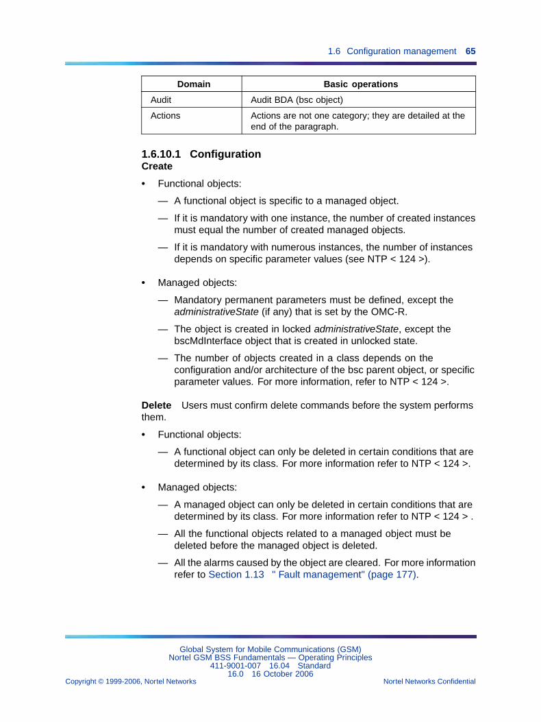
1.6 Configuration management 65
Domain Basic operations
Audit Audit BDA (bsc object)
Actions Actions are not one category; they are detailed at theend of the paragraph.
1.6.10.1 ConfigurationCreate
• Functional objects:
— A functional object is specific to a managed object.
— If it is mandatory with one instance, the number of created instancesmust equal the number of created managed objects.
— If it is mandatory with numerous instances, the number of instancesdepends on specific parameter values (see NTP < 124 >).
• Managed objects:
— Mandatory permanent parameters must be defined, except theadministrativeState (if any) that is set by the OMC-R.
— The object is created in locked administrativeState, except thebscMdInterface object that is created in unlocked state.
— The number of objects created in a class depends on theconfiguration and/or architecture of the bsc parent object, or specificparameter values. For more information, refer to NTP < 124 >.
Delete Users must confirm delete commands before the system performsthem.
• Functional objects:
— A functional object can only be deleted in certain conditions that aredetermined by its class. For more information refer to NTP < 124 >.
• Managed objects:
— A managed object can only be deleted in certain conditions that aredetermined by its class. For more information refer to NTP < 124 > .
— All the functional objects related to a managed object must bedeleted before the managed object is deleted.
— All the alarms caused by the object are cleared. For more informationrefer to Section 1.13 " Fault management" (page 177).
Global System for Mobile Communications (GSM)Nortel GSM BSS Fundamentals — Operating Principles
411-9001-007 16.04 Standard16.0 16 October 2006
Copyright © 1999-2006, Nortel Networks Nortel Networks Confidential
.
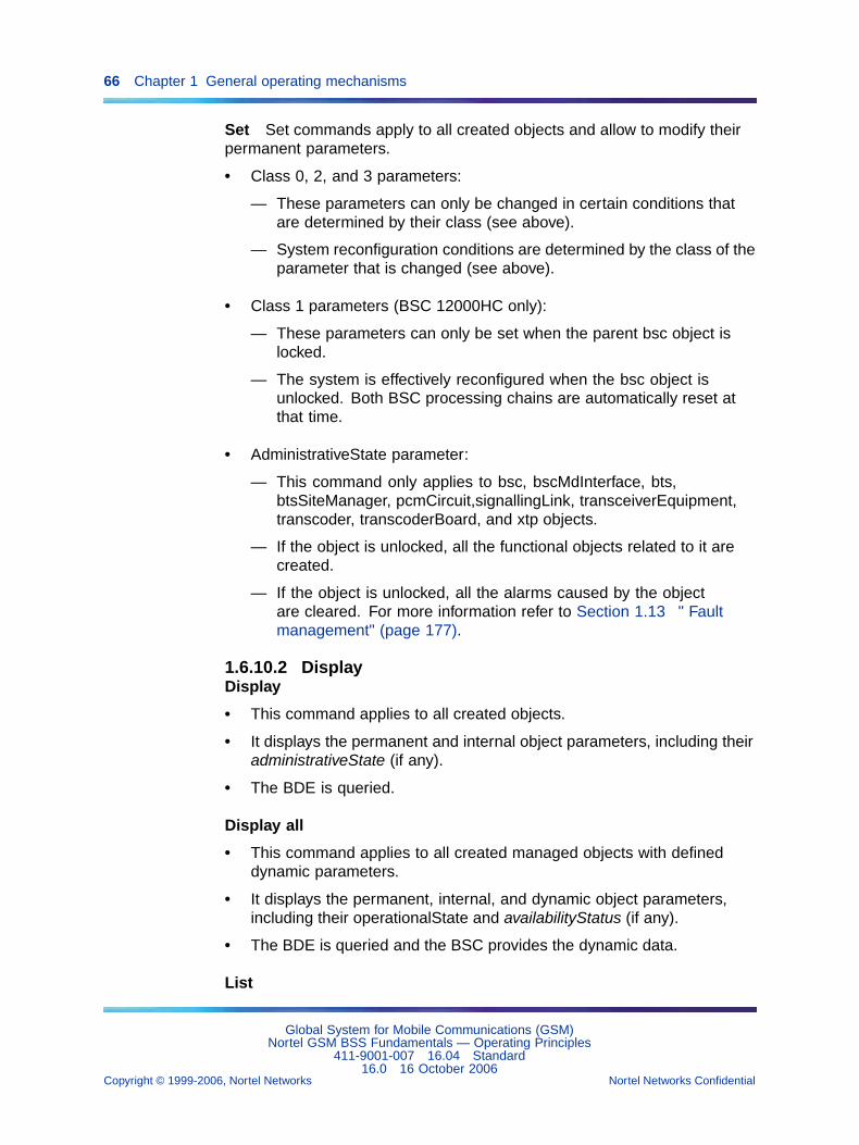
66 Chapter 1 General operating mechanisms
Set Set commands apply to all created objects and allow to modify theirpermanent parameters.
• Class 0, 2, and 3 parameters:
— These parameters can only be changed in certain conditions thatare determined by their class (see above).
— System reconfiguration conditions are determined by the class of theparameter that is changed (see above).
• Class 1 parameters (BSC 12000HC only):
— These parameters can only be set when the parent bsc object islocked.
— The system is effectively reconfigured when the bsc object isunlocked. Both BSC processing chains are automatically reset atthat time.
• AdministrativeState parameter:
— This command only applies to bsc, bscMdInterface, bts,btsSiteManager, pcmCircuit,signallingLink, transceiverEquipment,transcoder, transcoderBoard, and xtp objects.
— If the object is unlocked, all the functional objects related to it arecreated.
— If the object is unlocked, all the alarms caused by the objectare cleared. For more information refer to Section 1.13 " Faultmanagement" (page 177).
1.6.10.2 DisplayDisplay
• This command applies to all created objects.
• It displays the permanent and internal object parameters, including theiradministrativeState (if any).
• The BDE is queried.
Display all
• This command applies to all created managed objects with defineddynamic parameters.
• It displays the permanent, internal, and dynamic object parameters,including their operationalState and availabilityStatus (if any).
• The BDE is queried and the BSC provides the dynamic data.
List
Global System for Mobile Communications (GSM)Nortel GSM BSS Fundamentals — Operating Principles
411-9001-007 16.04 Standard16.0 16 October 2006
Copyright © 1999-2006, Nortel Networks Nortel Networks Confidential
.
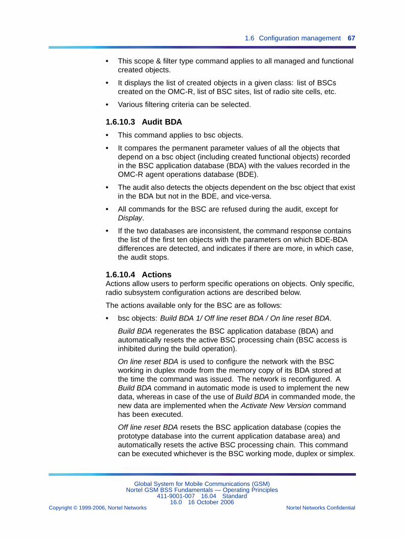
1.6 Configuration management 67
• This scope & filter type command applies to all managed and functionalcreated objects.
• It displays the list of created objects in a given class: list of BSCscreated on the OMC-R, list of BSC sites, list of radio site cells, etc.
• Various filtering criteria can be selected.
1.6.10.3 Audit BDA
• This command applies to bsc objects.
• It compares the permanent parameter values of all the objects thatdepend on a bsc object (including created functional objects) recordedin the BSC application database (BDA) with the values recorded in theOMC-R agent operations database (BDE).
• The audit also detects the objects dependent on the bsc object that existin the BDA but not in the BDE, and vice-versa.
• All commands for the BSC are refused during the audit, except forDisplay.
• If the two databases are inconsistent, the command response containsthe list of the first ten objects with the parameters on which BDE-BDAdifferences are detected, and indicates if there are more, in which case,the audit stops.
1.6.10.4 ActionsActions allow users to perform specific operations on objects. Only specific,radio subsystem configuration actions are described below.
The actions available only for the BSC are as follows:
• bsc objects: Build BDA 1/ Off line reset BDA / On line reset BDA.
Build BDA regenerates the BSC application database (BDA) andautomatically resets the active BSC processing chain (BSC access isinhibited during the build operation).
On line reset BDA is used to configure the network with the BSCworking in duplex mode from the memory copy of its BDA stored atthe time the command was issued. The network is reconfigured. ABuild BDA command in automatic mode is used to implement the newdata, whereas in case of the use of Build BDA in commanded mode, thenew data are implemented when the Activate New Version commandhas been executed.
Off line reset BDA resets the BSC application database (copies theprototype database into the current application database area) andautomatically resets the active BSC processing chain. This commandcan be executed whichever is the BSC working mode, duplex or simplex.
Global System for Mobile Communications (GSM)Nortel GSM BSS Fundamentals — Operating Principles
411-9001-007 16.04 Standard16.0 16 October 2006
Copyright © 1999-2006, Nortel Networks Nortel Networks Confidential
.

68 Chapter 1 General operating mechanisms
• bsc objects: Synchronize bsc clock
This command broadcasts the OMC-R agent reference date and time toa BSC. It can be launched on several BSCs at a time.
• bscMdInterface objects: Display circular file state / Close circular file /Open circular file / Clear circular file
These commands respectively display the state, close, open, and cleara circular file which contains spontaneous messages from a BSC.
• bts object: Force HandOvers
This command redirects the traffic handled by a serving cell towards itsneighbor cells. It can be launched on several cells at a time. It can beused before shutting down a serving cell in order to speed up the softrelease process.
• btsSiteManager objects: Display hardware configuration
Display hardware configuration displays the configuration of ardwareand is mainly used for system maintenance. It can be launched onseveral radio sites at a time. The BTS or BTSs that receive the messagereturn the information to the OMC-R.
• btsSiteManager objects: Display data configuration
Display data configuration optionally displays report information relatedto Edge capability of the BTS and TRX configuration data.
• btsSiteManager objects: Display hardware information
Display hardware information displays detailed information on hardwareof a BTS described by a btsSiteManager object (site, cell and TRXrelated equipment type, number, status...)
• btsSiteManager objects: Display data information
Display data information displays detailed information on configurationdata of a BTS described by a btsSiteManager object (SITE dataconfiguration display or SITE EDGE data display).
• btsSiteManager objects: Use btsSiteManager battery
Use btsSiteManager battery forces 1a BTS to use its battery if it is suchequipped. The battery must operate correctly.
• channel objects: Set channel state
Set channel state is used to block or unblock a logical channel supportedby a radio time slot.
• channel objects: Display channel state
Display channel state displays the states of all the logical channelssupported by a radio time slot. It can be launched on several time slots
Global System for Mobile Communications (GSM)Nortel GSM BSS Fundamentals — Operating Principles
411-9001-007 16.04 Standard16.0 16 October 2006
Copyright © 1999-2006, Nortel Networks Nortel Networks Confidential
.
1.6 Configuration management 69
at a time. It is also used to check the results of a block command on achannel object.
• signallingLink objects: Set inhibit
This command is used to inhibit or enable an SS7 signaling link on theA interface.
Inhibiting an SS7 link stops all the traffic on the link, but the link remainsin service (terrestrial traffic circuits remain preempted).
• transceiver objects: Display channel state
This command displays the states of all the logical channels supportedby all the radio time slots of a TDMA frame. It can be launched onseveral TDMA frames at a time.
• transceiverEquipment objects: Display hardware configuration
This command displays the configuration of a TRX/DRX hardware andis mainly used for system maintenance. It can be launched on severalTRX/DRXs at a time. The BTS or BTSs that receive the message returnthe information to the OMC-R.
Actions available only for BSC 12000HC Each action available only forthe BSC 12000HC are as follows:
• bsc objects: Display chain information
Display chain information displays the state of BSC 12000HC processingchain boards (chain A or B). It can be launched on several BSC12000HC at a time. The BSC 12000HC that receive the message returnthe information to the OMC-R.
• bsc objects: Kill chain
Kill chain resets one (active or standby) or both BSC 12000HC chains.The user must confirm the command. It has the following effect:
— active chain: The chain is reset and declared as standby; the otherchain is activated (switchover). Operations restart automatically butthe system is not reconfigured. Class 1 DP parameters are notupdated in applications, since the newly active chain is not reset.
— standby chain: The chain is reset when it can be reached. Thiscommand has no impact on operations (BSS operations are notinterrupted).
— active and standby chains: Both chains are reset. The firstprocessing chain that is operational again is declared active.Operations restart automatically and the system is reconfigured.Class 1 DP parameters are updated in the applications, since thenewly active chain has been reset.
Global System for Mobile Communications (GSM)Nortel GSM BSS Fundamentals — Operating Principles
411-9001-007 16.04 Standard16.0 16 October 2006
Copyright © 1999-2006, Nortel Networks Nortel Networks Confidential
.
70 Chapter 1 General operating mechanisms
• bsc objects: Suicide chain
Suicide chain resets a BSC 12000HC processing chain (A or B). Theuser must confirm the command. It has the following effect:
— If the chain is active when the BSC 12000HC receives the command,the chain is reset and is declared standby. The other chain isactivated (switchover). Operations restart automatically.
— If the chain is standby when the BSC 12000HC receives thecommand, it is reset when it can be reached.
1.6.11 Secure operation in reparenting1.6.11.1 OverviewThis feature provides a new Graphical User Interface (GUI) for the NetworkReconfiguration Procedure (NRP) tool. In the previous versions, each NRPprocedure was described on paper. This tool eliminates the need for paperprocedures.
This feature applies to version 15.0 of the BSS system. The NRPintegrations in this tool are:
• BSC reparenting
• BTS reparenting
• PCU reparenting
These procedures help the user to operate and reconfigure a BSS withoutreferring to paper procedures. This tool has the following enhancements:
• Reparenting procedures are performed using only mouse clicks, withouta UNIX window. The tool executes all the steps in one procedure.
• Typing errors are minimized because the paper procedure is no longerrequired.
• The tool can handle error cases and fallback in real time. In previousversions, errors were displayed in the log file.
• The tool provides a simple way to configure the network with a windowlook and feel.
1.6.11.2 ArchitectureThe tool is based on the client/server architecture. A tool server is installedon each OMC-R server. The tool server uses a socket connection with aspecific port number. The tool also uses Sybase client/server connections.The tool client connects to each server to obtain information such asconfiguration files, etc. or to execute a script on the server. Using thisarchitecture, the tool client can be installed on any UNIX station, even if it
Global System for Mobile Communications (GSM)Nortel GSM BSS Fundamentals — Operating Principles
411-9001-007 16.04 Standard16.0 16 October 2006
Copyright © 1999-2006, Nortel Networks Nortel Networks Confidential
.
1.6 Configuration management 71
is not an OMC-R station. The server/client tools enable communicationsbetween the local machine and available OMC-Rs. The tool can handle upto 4 active OMC-Rs, but it does not support a remote workstation.
1.6.11.3 SecurityThe server is in a listen mode at each OMC-R level via the defaultcommunications port. This port is only authorized to handle communicationsbetween the client and server with encrypted keys. For that reason, asecurity tool is implemented on each machine hosting a client and/or servertools.
The security tool interacts with following tools:
• Reparenting tool: gives it encrypted keys for the administration usersand remote server tools. This is done only for authorized administrationusers after their login using the security tool.
• Server tool: gives it its encrypted key and/or the result of the passwordcontained in the encrypted key for validity. All communications with theserver tools are dependent on the validity of the encrypted keys sent bythe client tools.
All operations performed by the reparenting tool via client/server toolsare indexed with encrypted keys. These keys are limited in time. Eachcommand sent to server tool through client tool has a unique key and cannot be reused.
The security tool has the following four main roles:
Administrator login security The operator must be logged-in withadministrator user privileges to execute the reparenting tool procedures.The reparenting tool connects to the security tool during the login processand the security tool displays a login window where the operator enters theadministrator name and password. The security tool checks the validity ofuser and password and returns an administrator-encrypted key, if the checkis ok. An error message is returned, if the security check fails.
Server key security To communicate with server tools, the reparentingtool must have a valid server-encrypted key per server tool. Thisserver-encrypted key is obtained via the security tool from the remote server.
Command send security To communicate with server tools, thecommands sent by the client tools must be followed by a valid and uniqueserver-encrypted key (one per command at a given time). The server toolexecutes this command, if the server-encrypted key is valid. If not, it returnsan error code status to the client tool.
Global System for Mobile Communications (GSM)Nortel GSM BSS Fundamentals — Operating Principles
411-9001-007 16.04 Standard16.0 16 October 2006
Copyright © 1999-2006, Nortel Networks Nortel Networks Confidential
.
72 Chapter 1 General operating mechanisms
Managing security information The security tool is used to:
• Create users and their passwords on the local and remote machine
• Change user name or password on the local and remote machine
• Add users on the local and remote machine
• Delete users from the local and remote machine
1.6.12 Improved build online performanceThe build on line improvements, introduced in V15.1, reduce the amountof time required for a BSC start-up. This start-up is required after the MIBis built.
Currently, the build on line is done in two phases:
• Phase 1: A MIB build that is done without interruption of services.
• Phase 2: A complete restart of the BSC that involves an interruptionof services.
The improvements reduce the duration of the interruption of services due tothe BSC restart. These improvements have no impact on the OMC-R.
The improvements include:
• restarting OMU applications (instead of resetting the OMU) to load newdata from the new MIB
• restarting some components earlier in the BSC restart cycle
• reducing the number of messages exchanged during PCM configuration
1.6.13 PCUSN configurationGeneral Packet Radio Service (GPRS) on the BSS. The PCUSN is aseparate node within the BSS which is based on a Nortel NetworksMultiservice Switch, Figure 16 "PCUSN in the BSS subsystem" (page74). It has a dedicated Operation, Administration and Maintenance (OAM)server running on a Sun Blade 150 or a Sun Blade 1500 workstation. ThePCU-OAM server is connected to the OMC-R through the OMC-R LAN.
The dedicated PCU-OAM server will not be needed when the OMC-Rserver is upgraded to a Sun FireTM V880 because the PCU-OAM serverfunctions will be transferred to it.
From V15.1, the Sun FireTM V890 server is used as the successor of theSun FireTM V880, and the Sun Blade 1500 workstation is used as thesuccessor of the Sun Blade 150 workstation.
Global System for Mobile Communications (GSM)Nortel GSM BSS Fundamentals — Operating Principles
411-9001-007 16.04 Standard16.0 16 October 2006
Copyright © 1999-2006, Nortel Networks Nortel Networks Confidential
.
1.6 Configuration management 73
The PCUSN is managed through specific software integrated in the server.The following two software packages are utilized on the PCU-OAM server:
• MDM (Multiservice Data Management) for the configuration and thefault management functions
• MDP (Management Data Provider) for the performance managementfunctions
The following day-to-day PCUSN operations are also integrated in theOMC-R for easy access:
• The GPRS access fault management is fully integrated within the GSMaccess faultmanagement. The fault and alarmmessages are forwardedin real time to the OMC-R database to be displayed on a Man--MachineInterface (MMI) workstation.
• Configuration management is accomplished with MDM hosted in theOMC-R server. It allows the operator to configure the PCUSN using anemulation window on each workstation.
• Other specific MDM applications are available on each MMI workstationto complete the integration of the functions for the GPRS PCUSN intothe OMC-R server.
Global System for Mobile Communications (GSM)Nortel GSM BSS Fundamentals — Operating Principles
411-9001-007 16.04 Standard16.0 16 October 2006
Copyright © 1999-2006, Nortel Networks Nortel Networks Confidential
.
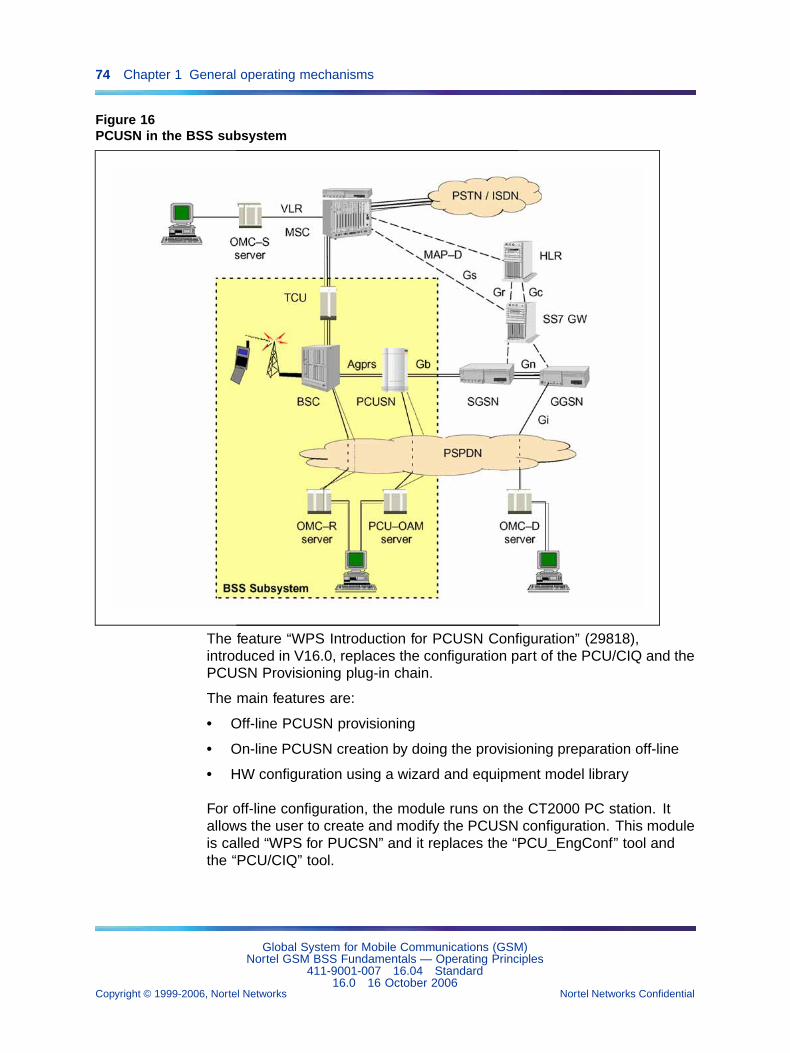
74 Chapter 1 General operating mechanisms
Figure 16PCUSN in the BSS subsystem
The feature “WPS Introduction for PCUSN Configuration” (29818),introduced in V16.0, replaces the configuration part of the PCU/CIQ and thePCUSN Provisioning plug-in chain.
The main features are:
• Off-line PCUSN provisioning
• On-line PCUSN creation by doing the provisioning preparation off-line
• HW configuration using a wizard and equipment model library
For off-line configuration, the module runs on the CT2000 PC station. Itallows the user to create and modify the PCUSN configuration. This moduleis called “WPS for PUCSN” and it replaces the “PCU_EngConf” tool andthe “PCU/CIQ” tool.
Global System for Mobile Communications (GSM)Nortel GSM BSS Fundamentals — Operating Principles
411-9001-007 16.04 Standard16.0 16 October 2006
Copyright © 1999-2006, Nortel Networks Nortel Networks Confidential
.
1.7 OMN access management 75
For on-line configuration, the module runs on the OMC-R workstationconnected to the PCU-OAM. This module is included on the current plug-in“PCUSN provisioning”. It replaces the DRF to CAS converter.
The PCUSN Provisioning process contains 3 main steps:
1. Creation/Modification of the PCUSN configuration off-line
2. Generation of commands (CAS files) for PCUSN creation or modification
3. Applying modifications on the PCUSN
Step 1 is managed by WPS. Steps 2 and 3 are managed by the PCUSNprovisioning plug-in
The reverse process contains 2 main steps:
1. Retrieve the current PCUSN configuration
2. Load the configuration on the off-line tool
Step 1 is managed by the PCUSN provisioning plug-in evolution. Step 2is managed by WPS.
1.7 OMN access management1.7.1 OMN access management for BSC 12000HC
1.7.1.1 OverviewThe Operations and Maintenance Network (OMN) is a packet switched datanetwork used for communications between the OMC-R and the BSS in thePublic Land Mobile Network (PLMN). The OMN is a layered communicationnetwork complying with the first four layers of the OSI reference model.
The OMC-R communicates with the BSC 12000HC across the OMNnetwork via the first four layers of the OSI reference model:
• Level 1 (physical layer) supports synchronous serial links (V35interface).
• Level 2 (LAP-B data layer) and Level 3 (packet switching network layer)comply with CCITT X.25 recommendations.
• Level 4 (transport layer) complies with CCITT X.214 and X.224standards.
The OMC-R has two OMN network access points. Both access points areused to handle communications with the BSC 12000HC on a load-sharingmode. If one access is inhibited, the other handles the other’s load untilthe other access is restored.
The following associations with a BSS can be opened on the OMN interface:
• INIT association (initialization)
• FAULT association (fault message transfer)
Global System for Mobile Communications (GSM)Nortel GSM BSS Fundamentals — Operating Principles
411-9001-007 16.04 Standard16.0 16 October 2006
Copyright © 1999-2006, Nortel Networks Nortel Networks Confidential
.
76 Chapter 1 General operating mechanisms
• MARK association (marking message transfer)
• PERF association (observation message transfer)
• TRACE association (trace message transfer)
• TRANSAC association (TGEs)
• UPDATE association (on-line build operation)
The INIT and FAULT associations are opened when the BSS/OMC-R link isestablished. The INIT association is opened first.
The MARK, PERF, TRACE, and TRANSAC associations are opened whenthe BSC 12000HC application database (BDA) is being built.
1.7.1.2 OMN access equipmentOMC-R equipment The standard OMC-R configuration includes one ortwo server(s) working and three local workstations.
Figure 1-16 (OMC-R communication equipment) shows the High SpeedInterface (HSI) board equipping the servers that provides the OMC-R withOMN access points. Each board controls two 64 kbit/s X.25 links.
For more details on the OMC-R equipment, refer to NTP < 006 >.
Global System for Mobile Communications (GSM)Nortel GSM BSS Fundamentals — Operating Principles
411-9001-007 16.04 Standard16.0 16 October 2006
Copyright © 1999-2006, Nortel Networks Nortel Networks Confidential
.
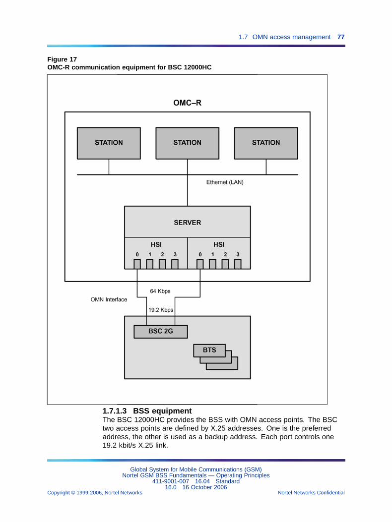
1.7 OMN access management 77
Figure 17OMC-R communication equipment for BSC 12000HC
1.7.1.3 BSS equipmentThe BSC 12000HC provides the BSS with OMN access points. The BSCtwo access points are defined by X.25 addresses. One is the preferredaddress, the other is used as a backup address. Each port controls one19.2 kbit/s X.25 link.
Global System for Mobile Communications (GSM)Nortel GSM BSS Fundamentals — Operating Principles
411-9001-007 16.04 Standard16.0 16 October 2006
Copyright © 1999-2006, Nortel Networks Nortel Networks Confidential
.
78 Chapter 1 General operating mechanisms
These ports are reserved for BSS/OMC-R links.
1.7.1.4 TerminalsIn addition to local workstations, the system contains the following:
• remote workstations, identical to the local workstations, and connectedto the OMC-R through routers across the X.25 network
• X terminals, selected by the operator, and connected across a local areanetwork through local or remote workstations
• remote access terminals, connected to the OMC-R by telephone link andmodem via a terminal server. The remote access terminals (RACEs)are PCs running under Windows.
1.7.1.5 Link managementPort selection principles Each BSS has one link with the OMC-R.
A BSS/OMC-R link uses an X.25 virtual circuit and has two transportconnections, one for transaction protocol messages (TGE, RGE, and eventreports), the other for file transfers (FTAM).
The network operator selects the access port for OMC-R communicationswhen the link is created. The OMN Access Management function canautomatically select the port to use on the basis of equal loads.
To select the correct access port, the X.25 network must not set up the calltransfer; therefore, this service should not be subscribed in the networksubscriptions.
Identifying a link Each BSS/OMC-R link in the OMC-R operationsdatabase (BDE) is described by a bscMdInterface object. Specificcommands on this object allow users to manage the BSC circular files thatcontain spontaneous messages transmitted by the BSC.
Creating a link The OMC-R always initiates BSS/OMC-R link setup. TheOMC-R is the calling party (outgoing connections) and the BSS are thecalled parties (incoming connections).
Since OMC-R and BSC each have two OMN access points, the accessused to set up a link are selected as follows:
• The preferred BSC 12000HC X.25 address is used. If the connectionfails, the backup address is used.
• The access port is selected by the user or the OMN Access Managementfunction (see above).
Global System for Mobile Communications (GSM)Nortel GSM BSS Fundamentals — Operating Principles
411-9001-007 16.04 Standard16.0 16 October 2006
Copyright © 1999-2006, Nortel Networks Nortel Networks Confidential
.
1.7 OMN access management 79
Link states A BSS/OMC-R link is managed as an equipment. ThebscMdInterface object that describes the link is characterized by three ISOstates: administrativeState, operationalState, and availabilityStatus.
Setting up a link The OMC-R agent attempts to set up a BSS/OMC-R linkwhen the bsc object is created and if the provided bscMdInterface objectdescribing the link is unlocked. Users may request link setup if the link hasbeen taken out of service (bscMdInterface object locked).
The operation consists of setting up a first transport connection from the listof parameters selected in descending order of preference.
If link setup procedure fails, attempts to reconnect the link are made atintervals defined in static configuration data.
OMC-R port selection by the user
1st choice destination = preferred BSC 12000HC access
2nd choice destination = backup BSC 12000HC access
Automatic OMC-R port selection
1st choice destination = preferred BSC 12000HC accessOMC-R port = least loaded port
2nd choice destination = backup BSC 12000HC accessOMC-R port = least loaded port
3rd choice destination = preferred BSC 12000HC accessOMC-R port = most loaded port
4th choice destination = backup BSC 12000HC accessOMC-R port = most loaded port
Releasing a link A BSS/OMC-R link is released by locking thebscInterface object that describes the link to disconnect the link betweenthe OMC-R and the BSC 12000HC. The link remains created but the BSC12000HC is out of reach and cannot communicate with the OMC-R.
Deleting a link User requests to delete a BSS/OMC-R link must beconfirmed and are accepted if the bsc object has been deleted. It is thenimpossible to communicate with the BSS.
Fault handling Since the OMC-R always initiates BSS/OMC-R link setup,any disconnect indication for which the user is not responsible is consideredabnormal.
Global System for Mobile Communications (GSM)Nortel GSM BSS Fundamentals — Operating Principles
411-9001-007 16.04 Standard16.0 16 October 2006
Copyright © 1999-2006, Nortel Networks Nortel Networks Confidential
.
80 Chapter 1 General operating mechanisms
The OMN Access Management function sends a hardware fault messageto the Fault Management function that generates a notification for OMC-Rusers.
Periodic attempts are made to set up the link. When the OMC-R starts up,the value of the interval between two attempts is set with a minimum valuedefined in static configuration data. It is reset when the connect attempt issuccessful. It is multiplied by two after each unsuccessful attempt untilit reaches a maximum value defined in static configuration data. Whenthe maximum value is reached, the attempts are stopped and the link isdeclared defective.
1.7.1.6 Access managementAccess port configuration The system command to start up the X.25layers assigns a logical number (0, 1, 2, or 3) to each physical X.25 accessport and selects the number of bits/s used: 64 kbits/s on ports 0 and 1(OMN access) and 9.6 kbits/s on other ports (reserved).
X.25 port configuration parameters are derived from network subscriptiondata.
Transport layer configuration The values of transport layer operatingparameters are stored in OMC-R system files. They must be compatiblewith the connected BSS transport layer definitions.
1.7.1.7 Management mechanismsLink configuration at start-up BSS/OMC-R links are configured from theinformation recorded in the OMC-R operations database (BDE).
1.7.1.8 Restoring links when servers switch overThe server switchover mechanism is used when the OMC-R has twoservers operating in duplex mode (standard configuration). It does not applyin single-server configurations with redundancy.
The standby server is declared active when the system switches over.
Since the operations database managed by the standby server is an exactcopy of the other server database, the link restoration mechanism usesthe information in the ex-standby server database to automatically restoreBSS/OMC-R links.
The normal start-up procedure is used.
Reconfiguring links at shutdown When the OMC-R shuts down,the OMN Access Management function automatically releases all theBSS/OMC-R links without changing their administrativeState.
Global System for Mobile Communications (GSM)Nortel GSM BSS Fundamentals — Operating Principles
411-9001-007 16.04 Standard16.0 16 October 2006
Copyright © 1999-2006, Nortel Networks Nortel Networks Confidential
.
1.7 OMN access management 81
When the OMC-R starts up again, the link configuration is restored as itwas before shutdown.
Choosing the OMC-R channel The network operator can select to usean A interface PCM time slot to handle the BSS/OMC-R link.
This choice is made when the BSC 12000HC is commissioned. In thatcase, a DPN100 equipment or a BayStack ASN is used to set the X.25connection between the BSC 12000HC and the OMC-R.
1.7.2 BSC 3000 OMN access management1.7.2.1 OverviewThe Operations and Maintenance Network (OMN) is a packet switched datanetwork used for communications between the OMC-R and the BSS in thePublic Land Mobile Network (PLMN). The OMN is a layered communicationnetwork complying with the layers of the OSI reference model.
The BSC 3000 cabinet and the OMC-R communicate through an OSIprotocol stack which covers the following needs:
• physical connection capability
LAN/RFC1006 (TCP/IP): two Ethernet links at up to 100 Mbps.
• association management capability
The associations manager is interfaced upon the Transport layer API.
• the FTAM (File transfer Access Management)
The FTAM contains the following characteristics:
— only the responder capability is needed
— restart and recovery capabilities are used
— content list types needed: NBS9, FTAM-1 and FTAM-3
The OSI protocol stack is compliant with the following recommendations:
• General
— ISO 7498/ITU-T X.200
Basic Reference model of Open Systems Interconnection
— ITU-T Q.811
Lower layer Protocol Profiles for the Q3 Interface
— ITU-T Q.812
Upper Layer Protocol Profiles for the Q3 Interface
• Application Layer
Global System for Mobile Communications (GSM)Nortel GSM BSS Fundamentals — Operating Principles
411-9001-007 16.04 Standard16.0 16 October 2006
Copyright © 1999-2006, Nortel Networks Nortel Networks Confidential
.
82 Chapter 1 General operating mechanisms
— ISO 8571
File Transfer, Access and Management Protocol
— ISO 8649/ITU-T X.217
Association Control Service Element Service
— ISO 8649/ITU-T X.227
Association Control Service Element Protocol
• Presentation Layer
— ISO 8822/ITU-T X.216
Connection-Oriented Presentation Definition
— ISO 8823/ITU-T X.226
Connection-Oriented Presentation Protocol
— ISO 8825/ITU-T X.209
ASN 1, Basic Service Element Protocol
• Session Layer
— ISO 8326/ITU-T X.215
Connection Oriented Session Service Definition
— ISO 8327/ITU-T X.225
Connection Oriented Session Protocol
• Transport Layer
— ISO 8072/ITU-T X.214
Connection Oriented Transport Service
— ISO 8073/ITU-T X.224
Connection Oriented Transport Protocol Class 4,2,0
— RFC 1006
OSI Transport Services on top of TCP
• Network Layer
— ISO 8208/ITU-T X.25
Packet Level Protocol for DTE
— ISO 8348/ITU-T X.213
Network Service Definition
Global System for Mobile Communications (GSM)Nortel GSM BSS Fundamentals — Operating Principles
411-9001-007 16.04 Standard16.0 16 October 2006
Copyright © 1999-2006, Nortel Networks Nortel Networks Confidential
.
1.7 OMN access management 83
• Datalink & Physical Layer
Essentially an Ethernet link:
LAN/RFC1006 (TCP/IP): two Ethernet links at up to 100 Mbps.
The OMC-R has two OMN network access points. Both access points areused to handle communications with the BSC 3000 on a load-sharingmode. If one access is inhibited, the other handles the other’s load untilthe other access is restored.
The following associations with a BSS can be opened on the OMN interface:
• INIT association (initialization)
• FAULT association (fault message transfer)
• MARK association (marking message transfer)
• PERF association (observation message transfer)
• TRACE association (trace message transfer)
• TRANSAC association (TGEs)
• UPDATE association (on-line build operation)
The INIT and FAULT associations are opened when the BSS/OMC-R link isestablished. The INIT association is opened first.
The MARK, PERF, TRACE, and TRANSAC associations are opened whenthe BSC 3000 application database (BDA) is being built.
1.7.2.2 OMN access equipmentThe standard OMC-R configuration includes one or two working server(s)and three local workstations.
Figure 18 "OMC-R communication equipment for BSC 3000" (page 84)shows the OMC-R equipment connected to an Ethernet Local Area Network(LAN) and the OMN connection between the OMC-R server and a BaseStation Controller (BSC 3000). The OMN LAN connection between theOMC-R server and the BSC 3000 uses two Ethernet links, which have acombined capacity up to 100 Mbps.
For more details on the OMC-R equipment, refer to NTP < 006 >
Global System for Mobile Communications (GSM)Nortel GSM BSS Fundamentals — Operating Principles
411-9001-007 16.04 Standard16.0 16 October 2006
Copyright © 1999-2006, Nortel Networks Nortel Networks Confidential
.
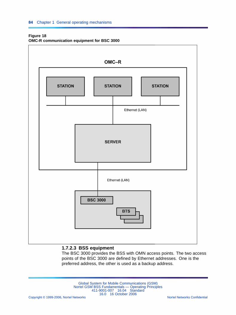
84 Chapter 1 General operating mechanisms
Figure 18OMC-R communication equipment for BSC 3000
1.7.2.3 BSS equipmentThe BSC 3000 provides the BSS with OMN access points. The two accesspoints of the BSC 3000 are defined by Ethernet addresses. One is thepreferred address, the other is used as a backup address.
Global System for Mobile Communications (GSM)Nortel GSM BSS Fundamentals — Operating Principles
411-9001-007 16.04 Standard16.0 16 October 2006
Copyright © 1999-2006, Nortel Networks Nortel Networks Confidential
.
1.7 OMN access management 85
1.7.2.4 TerminalsIn addition to local workstations, the system contains the following:
• remote workstations, identical to the local workstations, and connectedto the OMC-R.
• X terminals, selected by the operator, and connected across a local areanetwork through local or remote workstations
• remote access terminals, connected to the OMC-R by telephone link andmodem via a terminal server. The remote access terminals (RACEs)are PCs running under Windows.
1.7.2.5 Link managementPort selection principles Each BSS has one link with the OMC-R.
A BSS/OMC-R link uses an Ethernet Network.
The network operator selects the access port for OMC-R communicationswhen the link is created. The OMN Access Management function canautomatically select the port to use on the basis of equal loads.
Identifying a link Each BSS/OMC-R link in the OMC-R operationsdatabase (BDE) is described by a bscMdInterface object. Specificcommands on this object allow users to manage the BSC 3000 circular filesthat contain spontaneous messages transmitted by the BSC 3000.
Creating a link The OMC-R always initiates BSS/OMC-R link setup. TheOMC-R is the calling party (outgoing connections) and the BSS are thecalled parties (incoming connections).
Since OMC-R and BSC 3000 each have two OMN access points, theaccess used to set up a link are selected as follows:
• The preferred BSC 3000 Ethernet address is used. If the connectionfails, the backup address is used.
• The access port is selected by the user or the OMN Access Managementfunction (see above).
Link states A BSS/OMC-R link is managed as an equipment. ThebscMdInterface object that describes the link is characterized by three ISOstates: administrativeState, operationalState, and availabilityStatus.
Setting up a link The OMC-R agent attempts to set up a BSS/OMC-Rlink when the bsc e3 object is created and if the provided bscMdInterfaceobject describing the link is unlocked. Users may request link setup if thelink has been taken out of service (bscMdInterface object locked).
Global System for Mobile Communications (GSM)Nortel GSM BSS Fundamentals — Operating Principles
411-9001-007 16.04 Standard16.0 16 October 2006
Copyright © 1999-2006, Nortel Networks Nortel Networks Confidential
.
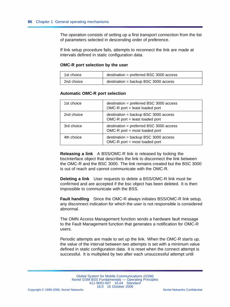
86 Chapter 1 General operating mechanisms
The operation consists of setting up a first transport connection from the listof parameters selected in descending order of preference.
If link setup procedure fails, attempts to reconnect the link are made atintervals defined in static configuration data.
OMC-R port selection by the user
1st choice destination = preferred BSC 3000 access
2nd choice destination = backup BSC 3000 access
Automatic OMC-R port selection
1st choice destination = preferred BSC 3000 accessOMC-R port = least loaded port
2nd choice destination = backup BSC 3000 accessOMC-R port = least loaded port
3rd choice destination = preferred BSC 3000 accessOMC-R port = most loaded port
4th choice destination = backup BSC 3000 accessOMC-R port = most loaded port
Releasing a link A BSS/OMC-R link is released by locking thebscInterface object that describes the link to disconnect the link betweenthe OMC-R and the BSC 3000. The link remains created but the BSC 3000is out of reach and cannot communicate with the OMC-R.
Deleting a link User requests to delete a BSS/OMC-R link must beconfirmed and are accepted if the bsc object has been deleted. It is thenimpossible to communicate with the BSS.
Fault handling Since the OMC-R always initiates BSS/OMC-R link setup,any disconnect indication for which the user is not responsible is consideredabnormal.
The OMN Access Management function sends a hardware fault messageto the Fault Management function that generates a notification for OMC-Rusers.
Periodic attempts are made to set up the link. When the OMC-R starts up,the value of the interval between two attempts is set with a minimum valuedefined in static configuration data. It is reset when the connect attempt issuccessful. It is multiplied by two after each unsuccessful attempt until
Global System for Mobile Communications (GSM)Nortel GSM BSS Fundamentals — Operating Principles
411-9001-007 16.04 Standard16.0 16 October 2006
Copyright © 1999-2006, Nortel Networks Nortel Networks Confidential
.
1.7 OMN access management 87
it reaches a maximum value defined in static configuration data. Whenthe maximum value is reached, the attempts are stopped and the link isdeclared defective.
1.7.2.6 Transport layer configurationThe values of transport layer operating parameters are stored in OMC-Rsystem files. They must be compatible with the connected BSS transportlayer definitions.
1.7.2.7 Management mechanismsLink configuration at start-up BSS/OMC-R links are configured from theinformation recorded in the OMC-R operations database (BDE).
1.7.2.8 Restoring links when servers switch overThe server switchover mechanism is used when the OMC-R has twoservers operating in duplex mode (standard configuration). It does not applyin single-server configurations with redundancy.
The standby server is declared active when the system switches over.
Since the operations database managed by the standby server is an exactcopy of the other server database, the link restoration mechanism usesthe information in the ex-standby server database to automatically restoreBSS/OMC-R links.
The normal start-up procedure is used.
Reconfiguring links at shutdown When the OMC-R shuts down,the OMN Access Management function automatically releases all theBSS/OMC-R links without changing their administrativeState.
When the OMC-R starts up again, the link configuration is restored as itwas before shutdown.
Choosing the OMC-R Channel There are two Ethernet ports whichmay be ‘called’ by the OMC-R, each with a different IP address. Both areaccessible for local maintenance with a local TML, but only the active onewill ′answer′ to the OMC-R ′call′.
The operator can choose to switch ports according to the active OMU.
If the active Ethernet link fails, the OMC-R tries to connect to the second IPaddress. Because the second IP address corresponds to the passive OMU,no connection will be established.
Global System for Mobile Communications (GSM)Nortel GSM BSS Fundamentals — Operating Principles
411-9001-007 16.04 Standard16.0 16 October 2006
Copyright © 1999-2006, Nortel Networks Nortel Networks Confidential
.
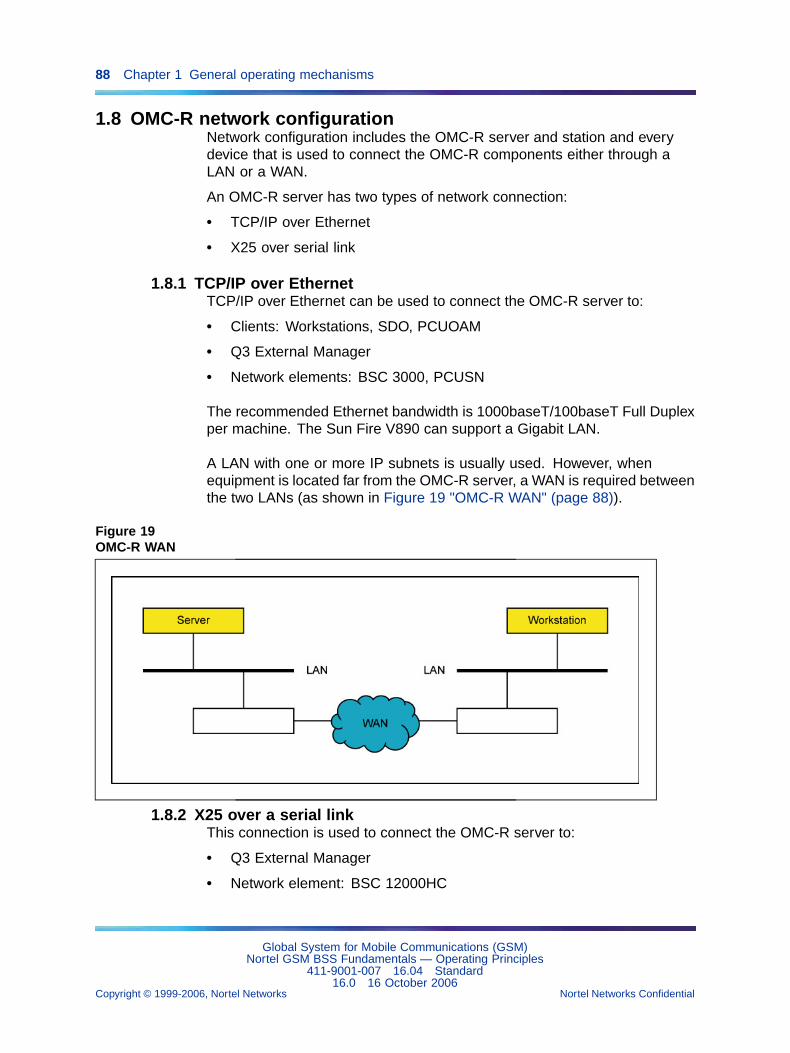
88 Chapter 1 General operating mechanisms
1.8 OMC-R network configurationNetwork configuration includes the OMC-R server and station and everydevice that is used to connect the OMC-R components either through aLAN or a WAN.
An OMC-R server has two types of network connection:
• TCP/IP over Ethernet
• X25 over serial link
1.8.1 TCP/IP over EthernetTCP/IP over Ethernet can be used to connect the OMC-R server to:
• Clients: Workstations, SDO, PCUOAM
• Q3 External Manager
• Network elements: BSC 3000, PCUSN
The recommended Ethernet bandwidth is 1000baseT/100baseT Full Duplexper machine. The Sun Fire V890 can support a Gigabit LAN.
A LAN with one or more IP subnets is usually used. However, whenequipment is located far from the OMC-R server, a WAN is required betweenthe two LANs (as shown in Figure 19 "OMC-R WAN" (page 88)).
Figure 19OMC-R WAN
1.8.2 X25 over a serial linkThis connection is used to connect the OMC-R server to:
• Q3 External Manager
• Network element: BSC 12000HC
Global System for Mobile Communications (GSM)Nortel GSM BSS Fundamentals — Operating Principles
411-9001-007 16.04 Standard16.0 16 October 2006
Copyright © 1999-2006, Nortel Networks Nortel Networks Confidential
.
1.9 AMR Overview 89
with a bandwidth up to 2048 kbps.
1.9 AMR OverviewThe feature AMR [SV713 - AMR full rate (FR); SV885 AMR Half rate (HR)]was introduced in V14. AMR (Adaptive Multi-Rate) enables the BSS tointroduce sophisticated traffic management features which deal with callquality management and capacity improvements.
AMR introduction induces creations or modifications of following algorithmsin the BSS:
• AMR management: AMR vocoders, dedicated VAD (Voice ActiveDetection)/DTX, link adaptation mechanisms, RATSCCH (Robust ARMTraffic Synchronized Control Channel) channel and TRAU (Transcodingand Rate Adaptor Unit) frames.
• To guarantee good voice quality, the choice between a half rate and afull rate channel are usually determined by a threshold based on radiocriteria. AMR half rate channels are now allocated only during heavytraffic periods. By selecting more aggressive radio thresholds, you canget more radio capacity for the same number of TRX.
• L1m (Layer one Management) mechanisms: adaptation of currentmechanisms (power control and handover to the intrinsic quality ofAMR channel.
• TMG (Traffic ManaGement) mechanisms: allocation and managementof AMR channels and especially half rate channel.
Up to V14, L1m algorithms are common for all types of dedicated channels,but due to performances of AMR channels:
• an FR AMR channel, especially with low codec mode, is more resistantthan the normal FR channel,
• an HR AMR channel is more sensitive to interference than the normalFR channel.
• some new mechanisms dedicated for AMR channels have beendesigned.
These mechanisms are mainly based on "requested codec mode" in uplinkand downlink paths, which is the best representation of the quality in thiscase. For this reason, RxQual criterion is not used in L1m algorithm,dealing with AMR channel.
In V14, only the L1m V2 introduced in V12 is available for DCU4 and DRX,In V14, only the L1m V1 is available for DCU2. But, to allow a smooth AMRintroduction, this new AMR L1m can be deactivated, thanks a dedicatedparameter.
Global System for Mobile Communications (GSM)Nortel GSM BSS Fundamentals — Operating Principles
411-9001-007 16.04 Standard16.0 16 October 2006
Copyright © 1999-2006, Nortel Networks Nortel Networks Confidential
.
90 Chapter 1 General operating mechanisms
For more information, refer to NTP <126>.
1.9.1 BSS capacity1.9.1.1 Abis PCMAMR half Rate allows twice the number of calls that could be carried ona Abis PCM.
1.9.1.2 BSC 3000 capacityThe introduction of AMR on BSC 3000 introduces:
• the handover between half rate and full rate TCH, in order to adapt theradio link to radio conditions
• more complex algorithm
1.9.1.3 TCU 3000 capacityAMR introduce more complexity on TCU 3000, but no capacity reductioncompared with EFR (enhancement full rate) or FR (Full rate) calls isexpected.
For more information refer to NTP <126>.
1.9.2 Effect of satellite links on AMR services link adaptationmechanism
The Satellite link on BSS Abis (E1) feature (26834), introduced in V15.1,allows the implementation of satellite links instead of terrestrial links on theAbis interface. Feature 26834 is an optional feature.
For AMR services, a link adaptation mechanism is used to switch fromone codec to another one. The efficiency of this mechanism depends onits reactivity (around 160 milliseconds for the downlink path). The use ofsatellite links increases this delay (by around 550 milliseconds). The linkadaptation tables must be tuned accordingly.
1.9.3 AMR based on trafficIn order to guarantee good voice quality, the choice between a half rateand a full rate channel are usually determined by a threshold based onradio criteria. AMR half rate channels are now allocated only during heavytraffic periods.
Thanks to this strategy, you can select more aggressive radio thresholdsand then get more radio capacity for the same number of TRX.
Global System for Mobile Communications (GSM)Nortel GSM BSS Fundamentals — Operating Principles
411-9001-007 16.04 Standard16.0 16 October 2006
Copyright © 1999-2006, Nortel Networks Nortel Networks Confidential
.
1.10 Software management 91
1.9.4 FACCH repetitionWith the feature 30296 (FACCH repetition), introduced in V16.0, the BTScan re-transmit the FACCH (Fast Associated Control CHannel) frames inthe downlink without waiting for the acknowledgement from the mobile. TheFACCH is a dedicated signaling channel (in the Um interface).
The BTS uses this repeated downlink FACCH functionality when FR lowrate codecs are used and when the first transmission fails.
The purpose of the feature is to secure the handover procedure in poorradio conditions (with AMR FR). The implementation is consistent with the3GPP approved contribution GP-050905.
Enhanced mobiles have the possibility to combine both repeated frames.Legacy mobiles can also benefit since the decoding probability is improvedand this results in a faster handover. The expected benefit for mobiles usingsoft combining is about 4 dB gain and about 2 dB gain for legacy mobiles.
The feature applies to the BTS 18000, the e-cell, and the BTS S8000 andS12000 equipped with e-DRX or DRX-ND3. The feature does not apply toother BTS hardware.
The parameter enableRepeatedFacchFr (bts object) is used toenable/disable the feature. For a description, see NTP < 124 >.
Repeated FACCH frames are not considered by the Call Drop Analysisfeature.
REJects (for each repeated I-frame, the mobile may receive an I-frame withan unexpected sequence number and so send a REJect frame to the BTS)are captured in the LAPDm history.
The feature leads to better call retaining in badly covered areas or highlyinterfered areas. Acceptable voice quality is maintained due to the robustAMR/FR codec. Since voice quality may be degraded slightly during thehandover procedures (because of repeated frame stealing), the preventiveretransmission scheme should be triggered only in bad radio conditions.
1.10 Software management1.10.1 Definitions
BSS entity For the radio subsystem entity driven by software = BSC12000HC; BCF (BTS switching and control unit), TRX/DRX (radio BTStransceivers), and TCB (TCU transcoding boards).
Global System for Mobile Communications (GSM)Nortel GSM BSS Fundamentals — Operating Principles
411-9001-007 16.04 Standard16.0 16 October 2006
Copyright © 1999-2006, Nortel Networks Nortel Networks Confidential
.
92 Chapter 1 General operating mechanisms
For the radio subsystem entity driven by software = BSC 3000, BCF (BTSswitching and control unit), TRX/DRX (radio BTS transceivers), and TCU3000.
BSS object Object of class bsc (BSC 12000HC or BSC e3),btsSiteManager (radio site), transceiverEquipment (TRX/DRX),transcoderBoard (TCB) or tcu e3 used in the OMC-R operations database.
Software type Specific BSS entity software.
EFT Set of transferable files containing a given type of software that doesnot depend on the equipment hardware. EFT files are an indivisible entity.
From V12 onwards, EFT files can be delivered compressed. A specificheader is present at the beginning of a compressed EFT file. In the absenceof this header, the file is considered non compressed.
Both compressed or non compressed files can be downloaded from thesame EFT to a BSC 12000HC. The decompression of a file is started onlywhen the file has been entirely transferred.
Since in parallel a compressed file can be downloaded while another isbeing uncompressed, file transfer on X.25 and downloading durations arereduced.
delivery In the case of the BSC/TCU 3000, delivery is defined as beinga collection of EFTs, each one of them containing a unit of file with theextension ".LIV". Delivery is a physical object.
executableSoftware The executableSoftware is the name of thedelivery.
Both compressed or non compressed files can be downloaded from thesame executableSoftware to a BSC 3000. The decompression of a file isstarted only when the file has been entirely transferred.
Since in parallel a compressed file can be downloaded while another isbeing uncompressed, file transfer on Ethernet and downloading durationsare reduced.
DLU (Data Load Unit) BTS variable configuration file associated witha BCF-type EFT that allows to configure the software according to theequipment hardware.
STF (File Transfer Service) File transfer service used to copy EFTs ontothe OMC-R server disks and download EFTs onto a BSC disk.
Global System for Mobile Communications (GSM)Nortel GSM BSS Fundamentals — Operating Principles
411-9001-007 16.04 Standard16.0 16 October 2006
Copyright © 1999-2006, Nortel Networks Nortel Networks Confidential
.
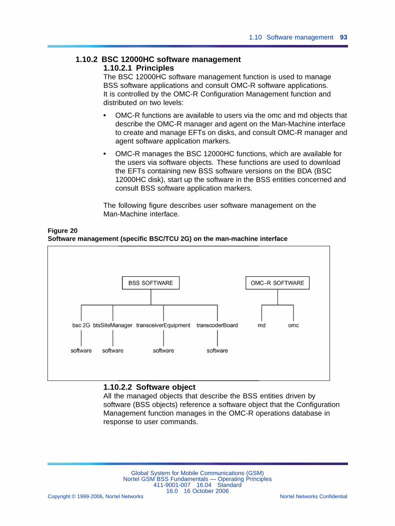
1.10 Software management 93
1.10.2 BSC 12000HC software management1.10.2.1 PrinciplesThe BSC 12000HC software management function is used to manageBSS software applications and consult OMC-R software applications.It is controlled by the OMC-R Configuration Management function anddistributed on two levels:
• OMC-R functions are available to users via the omc and md objects thatdescribe the OMC-R manager and agent on the Man-Machine interfaceto create and manage EFTs on disks, and consult OMC-R manager andagent software application markers.
• OMC-R manages the BSC 12000HC functions, which are available forthe users via software objects. These functions are used to downloadthe EFTs containing new BSS software versions on the BDA (BSC12000HC disk), start up the software in the BSS entities concerned andconsult BSS software application markers.
The following figure describes user software management on theMan-Machine interface.
Figure 20Software management (specific BSC/TCU 2G) on the man-machine interface
1.10.2.2 Software objectAll the managed objects that describe the BSS entities driven bysoftware (BSS objects) reference a software object that the ConfigurationManagement function manages in the OMC-R operations database inresponse to user commands.
Global System for Mobile Communications (GSM)Nortel GSM BSS Fundamentals — Operating Principles
411-9001-007 16.04 Standard16.0 16 October 2006
Copyright © 1999-2006, Nortel Networks Nortel Networks Confidential
.
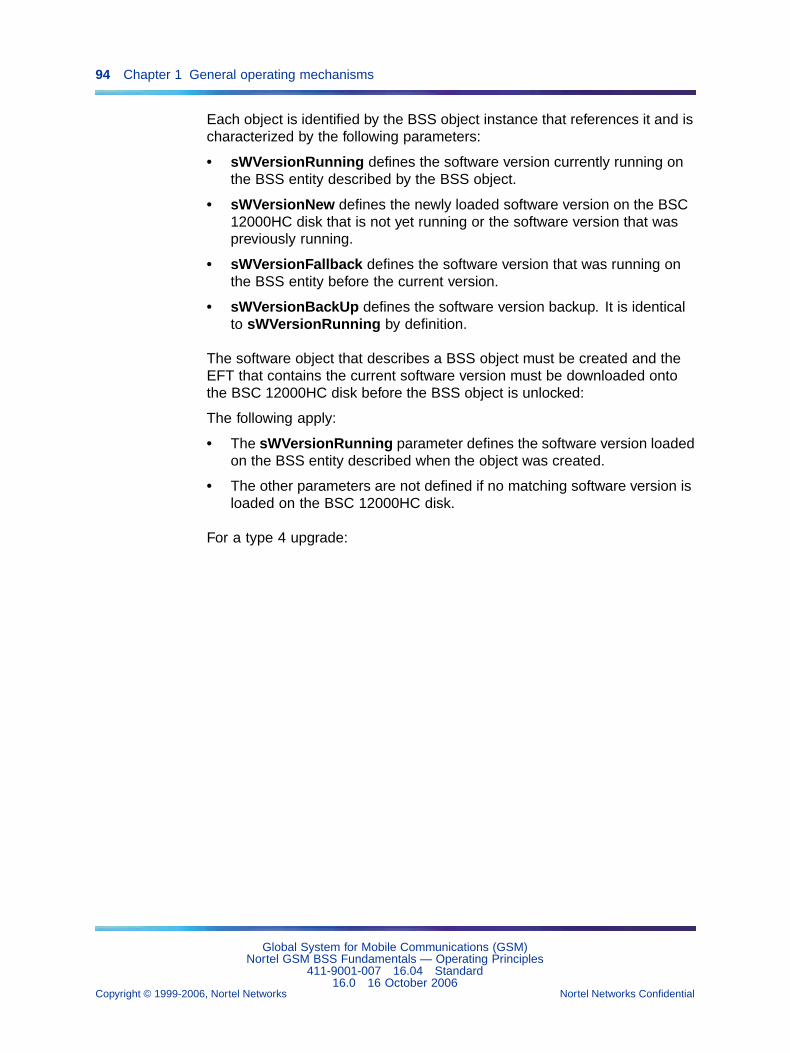
94 Chapter 1 General operating mechanisms
Each object is identified by the BSS object instance that references it and ischaracterized by the following parameters:
• sWVersionRunning defines the software version currently running onthe BSS entity described by the BSS object.
• sWVersionNew defines the newly loaded software version on the BSC12000HC disk that is not yet running or the software version that waspreviously running.
• sWVersionFallback defines the software version that was running onthe BSS entity before the current version.
• sWVersionBackUp defines the software version backup. It is identicalto sWVersionRunning by definition.
The software object that describes a BSS object must be created and theEFT that contains the current software version must be downloaded ontothe BSC 12000HC disk before the BSS object is unlocked:
The following apply:
• The sWVersionRunning parameter defines the software version loadedon the BSS entity described when the object was created.
• The other parameters are not defined if no matching software version isloaded on the BSC 12000HC disk.
For a type 4 upgrade:
Global System for Mobile Communications (GSM)Nortel GSM BSS Fundamentals — Operating Principles
411-9001-007 16.04 Standard16.0 16 October 2006
Copyright © 1999-2006, Nortel Networks Nortel Networks Confidential
.
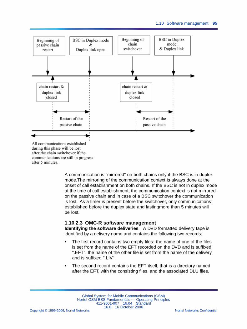
1.10 Software management 95
A communication is "mirrored" on both chains only if the BSC is in duplexmode.The mirroring of the communication context is always done at theonset of call establishment on both chains. If the BSC is not in duplex modeat the time of call establishment, the communication context is not mirroredon the passive chain and in case of a BSC switchover the communicationis lost. As a timer is present before the switchover, only communicationsestablished before the duplex state and lastingmore than 5 minutes willbe lost.
1.10.2.3 OMC-R software managementIdentifying the software deliveries A DVD formatted delivery tape isidentified by a delivery name and contains the following two records:
• The first record contains two empty files: the name of one of the filesis set from the name of the EFT recorded on the DVD and is suffixed".EFT", the name of the other file is set from the name of the deliveryand is suffixed ".LIV".
• The second record contains the EFT itself, that is a directory namedafter the EFT, with the consisting files, and the associated DLU files.
Global System for Mobile Communications (GSM)Nortel GSM BSS Fundamentals — Operating Principles
411-9001-007 16.04 Standard16.0 16 October 2006
Copyright © 1999-2006, Nortel Networks Nortel Networks Confidential
.
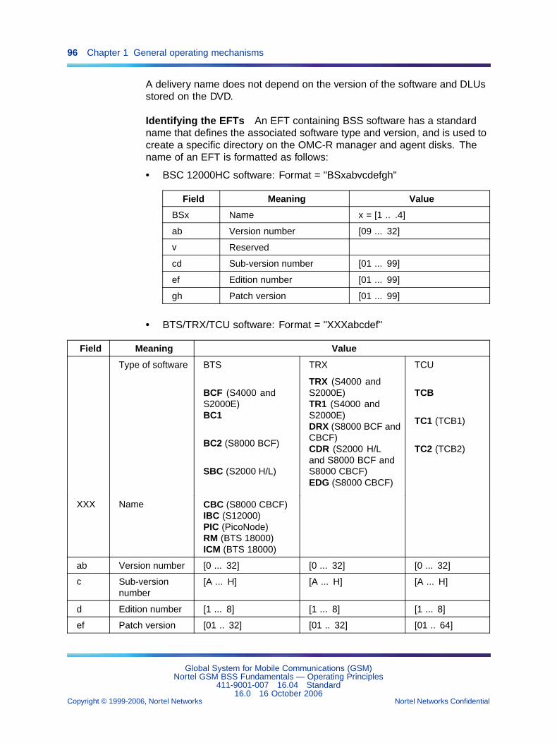
96 Chapter 1 General operating mechanisms
A delivery name does not depend on the version of the software and DLUsstored on the DVD.
Identifying the EFTs An EFT containing BSS software has a standardname that defines the associated software type and version, and is used tocreate a specific directory on the OMC-R manager and agent disks. Thename of an EFT is formatted as follows:
• BSC 12000HC software: Format = "BSxabvcdefgh"
Field Meaning Value
BSx Name x = [1 .. .4]
ab Version number [09 ... 32]
v Reserved
cd Sub-version number [01 ... 99]
ef Edition number [01 ... 99]
gh Patch version [01 ... 99]
• BTS/TRX/TCU software: Format = "XXXabcdef"
Field Meaning Value
Type of software BTS
BCF (S4000 andS2000E)BC1
BC2 (S8000 BCF)
SBC (S2000 H/L)
XXX Name CBC (S8000 CBCF)IBC (S12000)PIC (PicoNode)RM (BTS 18000)ICM (BTS 18000)
TRX
TRX (S4000 andS2000E)TR1 (S4000 andS2000E)DRX (S8000 BCF andCBCF)CDR (S2000 H/Land S8000 BCF andS8000 CBCF)EDG (S8000 CBCF)
TCU
TCB
TC1 (TCB1)
TC2 (TCB2)
ab Version number [0 ... 32] [0 ... 32] [0 ... 32]
c Sub-versionnumber
[A ... H] [A ... H] [A ... H]
d Edition number [1 ... 8] [1 ... 8] [1 ... 8]
ef Patch version [01 .. 32] [01 .. 32] [01 .. 64]
Global System for Mobile Communications (GSM)Nortel GSM BSS Fundamentals — Operating Principles
411-9001-007 16.04 Standard16.0 16 October 2006
Copyright © 1999-2006, Nortel Networks Nortel Networks Confidential
.
1.10 Software management 97
Identifying the DLUs The name of a DLU configuration file is coded as"Fabcyyyz", where:
• abc is the software version number (ab = [08 to 32], c = [A to H]).
• yyy is the hardware configuration index (0 to 9, A to V) of the DLU file forthe equipment.
• z is the revision factor (0 to 9, A to V).
The DLU name is used to create a special subdirectory under the associatedEFT directory on the OMC-R manager and agent disks.
BSS software management by the OMC-R manager User commandsare available when using the OMC object:
• Read Gigatape
Copy a set of transferable files containing a BSS software version andthe associated DLUs supplied on DVD to the OMC-R manager disks..
The DVD must be installed in the drive of the active OMC-R managerserver.
The delivery and EFT names supplied on the tape are displayed insession logs when the copy is complete. The EFT name defines theOMC-R manager disk directory where the EFT is stored.
• Download EFT to md
Copy an EFT containing a BSS software version and the associatedDLUs from OMC-R manager disks onto OMC-R agent disks.
The EFT to download is identified by name. The OMC-R agent diskdirectory used to store the EFT must be created (see next Paragraph).
• Download and validate EFT from Gigatape to md
Copy a set of transferable files containing a BSS software version andthe associated DLUs supplied on DVD to the OMC-R manager andagent disks, and validate the EFT and DLU downloading to disk.
This command enables to gather in one command the two previouslisted commands and the two creating commands described in thefollowing subparagraph.
• Delete EFT
Delete an EFT containing a BSS software version and the associatedDLUs from the OMC-R manager disks.
The EFT is identified by name. The disk directory and all the files itcontains are deleted.
Global System for Mobile Communications (GSM)Nortel GSM BSS Fundamentals — Operating Principles
411-9001-007 16.04 Standard16.0 16 October 2006
Copyright © 1999-2006, Nortel Networks Nortel Networks Confidential
.
98 Chapter 1 General operating mechanisms
• List EFT
Display the list of EFTs and associated DLUs created on theOMC-R manager disks. The OMC-R manager file manager suppliestheinformation.
BSS software management by the OMC-R agent This function performstasks that may cause the OMC-R operations database (BDE) to be updated.
User commands are available using the md object as follows:
• Create EFT dir
Create a directory on the OMC-R agent disks to store an EFT containinga BSS software version and the associated DLUs.
The directory is identified by the name of the EFT due to be downloadednext (see previous Paragraph):
— BSC 12000HC software: The EFT creation is not already validated(see next).
— BCF software: If the EFT creation is already validated, the commandcan be used to associate more DLU files to the EFT.
— TRX/DRX and TCB software: The EFT creation is not alreadyvalidated (see next).
• Create EFT
Validate an EFT and associated DLU downloading to the OMC-R agentdisks (see previous Paragraph) to declare the BSS software version tothe OMC-R agent Software Management function.
If the command follows a Create EFT dir command used toassociate more DLU files to the EFT, downloading the EFT to a BSC12000HC disk is forbidden until the command is complete.
The directories corresponding to an EFT delivery that is not validatedare automatically cleared and deleted when they are more than threedays old.
• Delete EFT
Delete an EFT and the associated DLUs from the OMC-R agent disks.The disk directory and all the files it contains are deleted.
The command is refused if the software version is referenced by asoftware object created in the BDE.
• List EFT
Display the list of EFTs and associated DLUs created on the OMC-Ragent disks. The OMC-R agent file manager supplies the information.
• List (object instances referencing an EFT)
Global System for Mobile Communications (GSM)Nortel GSM BSS Fundamentals — Operating Principles
411-9001-007 16.04 Standard16.0 16 October 2006
Copyright © 1999-2006, Nortel Networks Nortel Networks Confidential
.
1.10 Software management 99
Display the list of software objects that reference a named EFT. TheBDE supplies the information.
This command is a multiple-type command (scope & filter) and cannotbe accessed using a software object. It can be used before deleting anEFT to check whether the EFT is referenced.
EFT loading sequence BSS software loading commands must beentered in the following order to allow the OMC-R Software Managementfunction to organize software versions correctly:
• Read GigaTape (omc object)
• Create EFT dir (md object)
• Download EFT to md (omc object)
• Create EFT (md object)
After the system validates the last command, the EFT is effectivelyaccepted by the OMC-R agent Software Management function and can bedownloaded to the BSC 12000HC disk.
Use the Download and validate EFT from Gigatape to mdcommand instead of the four separate commands listed above.
Consulting BSS and OMC-R software markers This function identifiesthe software applications currently running on BSS entities and on OMC-Rmanager and agent servers.
The marker files are stored in BSC 12000HC and OMC-R server diskdirectories. A software application marker contains the following information:
• type (BSS entity or server) and name of the associated entity
• name and number of the application version (a version number isencoded in Vab_cd Enn format)
• a variable comments area, depending on the application type (usuallythe date when the application was generated)
Consulting BSS software markers The Display markers commandon any created software object provides the following information:
• software versions running on a BSC 12000HC, radio site BCF, radiotransceiver (TRX/DRX), or remote transcoding unit (TCB)
• PROM software versions in the same entities
• BSC 12000HC prototype application database (BDA) configuration files
Global System for Mobile Communications (GSM)Nortel GSM BSS Fundamentals — Operating Principles
411-9001-007 16.04 Standard16.0 16 October 2006
Copyright © 1999-2006, Nortel Networks Nortel Networks Confidential
.
100 Chapter 1 General operating mechanisms
The command run invokes a reference file updated by the BSC 12000HCthat contains the list of BSS markers. The BSC 12000HC then sends theinformation to the OMC-R.
A reference file updating request is sent to the BSC 12000HC and theresulting information is provided to users.
Consulting OMC-R software markers The Display markerscommand on the md object identifies the OMC-R agent active and passiveserver software applications.
The Display server markers and Display workstationmarkers commands on the omc object respectively identify the OMC-Rmanager active and passive server software applications, and the softwareapplications of a given workstation.
The file manager provides information on the application software that isrunning in the servers and workstations.
1.10.2.4 BSC 12000HC disk configurationThe BSC 12000HC disk is divided into partitions defined in staticconfiguration data. Some partitions are dedicated to BSS softwaremanagement. The simplified outline of the disk configuration that follows isonly intended to help users to understand the disk management structure.
The hard disk of the BSC 12000HC houses:
• the BSC 12000HC software, which is split up as follows:
— The active partitions :MB_CODE: and :MB_PROTO: contain thecurrent BSC software version (actually running):
– The :MB_CODE: partition contains the application code.
– The :MB_PROTO: partition contains the prototype applicationdatabase (BDA) configuration files.
— The delivery partitions :LIV_COD: and :LIV_PRO: contain thesoftware version to be delivered if any (either a new version of BSC12000HC software downloaded to the BSC 12000HC disk or thepreviously running version):
– The :LIV_COD: partition contains the application code.
– The :LIV_PRO: partition contains the prototype applicationdatabase (BDA) configuration files.
• the BCF and TRX/DRX software, which is stored as follows:
The :BTS: partition contains GSM site entity software versions (BCF andTRX/DRX) downloaded to the BSC 12000HC disk.
Global System for Mobile Communications (GSM)Nortel GSM BSS Fundamentals — Operating Principles
411-9001-007 16.04 Standard16.0 16 October 2006
Copyright © 1999-2006, Nortel Networks Nortel Networks Confidential
.
1.10 Software management 101
• the TCB software, which is stored as follows:
The :TCB: partition contains remote TCU 2G transcoding board (TCB)software versions downloaded to the BSC 12000HC disk.
1.10.2.5 Downloading managementThis function allows users to download new BSS software versions to theBSC 12000HC disks from the EFT created and validated on the OMC-Ragent disks.
User command The Download command is available for all createdsoftware objects.
Downloading consists of copying a BSS software version from the OMC-Ragent disks to the BSC 12000HC disk related to the selected BSS object.
The user enters the EFT name.
EFT and associated DLU files are stored in dedicated directory(ies). Thedirectory and subdirectories are identified from the information suppliedby the EFT.
Requirements The main requirements for the BSC 12000HC are:
• No change software version command is executing on the selectedBSC 12000HC.
• No create or download new DLU file command is being processed forthe concerned EFT.
• Up to five download commands that involve different BSC 12000HCscan be executed at the same time by system users. After that, theOMC-R refuses the commands.
The STF service provided by the OMC-R agent and the MTF service on theBSC 12000HC manages the download command routine.A download command can be launched on several BSC 12000HCs at a time.
BSC 12000HC software downloading All the files in the delivery partition:LIV_COD: are deleted except for the FCP_VCHG.TXT file.
Only the EFT files that are different in the current version (stored in :MB_xxx:partitions) are transferred to the corresponding :LIV_xxx: partitions. TheBSC 12000HC file transfer service copies the files that are identical in thecurrent version from the active partition to the delivery partition.
Global System for Mobile Communications (GSM)Nortel GSM BSS Fundamentals — Operating Principles
411-9001-007 16.04 Standard16.0 16 October 2006
Copyright © 1999-2006, Nortel Networks Nortel Networks Confidential
.
102 Chapter 1 General operating mechanisms
BTS and TCB software downloading by the BSC 12000HC All the filesin the dedicated :BTS: or :TCB: partition on the BSC 12000HC disk that arenot associated with a software version referenced in the BDE are deleted(files not referenced by a software object).
Only the EFT files not stored in the dedicated BSC 12000HC disk partitionare transferred. The list of files is obtained by comparing them with existingfiles.
The maximum number of site background downloading processes that canbe performed simultaneously by a BSC 12000HC is eight.
Consequences
• BSC 12000HC software:
— If the sWVersionNew or sWVersionFallback parameter wasdefined before downloading, the reference to the associatedsoftware version is deleted.
— The sWVersionNew parameter is defined with the newly loadedsoftware version.
— The sWVersionRunning is not changed.
— The sWVersionFallback is not defined.
• BCF, TRX/DRX, and TCB software:
— If the sWVersionNew parameter was defined before downloading,the reference to the associated software version is deleted.
— The sWVersionNew parameter is defined with the newly loadedsoftware version.
— The sWVersionRunning and sWVersionFallback parameters arenot changed.
DRX automatic downloading See Section 1.10.7 "Automaticdownloading of DRX software" (page 125).
1.10.2.6 BTS software background downloading
CAUTIONCustomer specificIndicates that specific equipment and specific software (such asspecific software in the BSC) dedicated to a specific application isused and that therefore the feature is not available for all standardGSM users.
Global System for Mobile Communications (GSM)Nortel GSM BSS Fundamentals — Operating Principles
411-9001-007 16.04 Standard16.0 16 October 2006
Copyright © 1999-2006, Nortel Networks Nortel Networks Confidential
.
1.10 Software management 103
This function allows the downloading of BTS software while BTSs are stillworking and, in doing so, reduces the out of service time during softwareupgrades. It requires BTSs support of the centralized downloading protocol.
The update process of BTS software consists of two separate phases:
• The first one, the longest, is the software downloading. The BTS is stillworking and is not yet upgraded.
• The second one is the activation of the new software. During this phase,the service is interrupted for a short time.
User commands OMC-R commands are provided to manage theupgrade process:
• The "BTS background download" command launches the softwaredownloading, which can be immediately followed by an activation.
• The "BTS background activate" command activates the new software.
• The "BTS background abort" command interrupts the softwaredownloading.
• The "BTS background download status" provides information onsoftware downloading.
1.10.2.7 Version managementThis function allows users to manage BSS software versions. The OMC-Roperations database (BDE) is updated.
User commands The user commands for changing software versions areavailable for all created software objects:
• The Activate new version command starts up a new softwareversion in a BSS entity.
• The Return to previous version command reactivates an oldsoftware version in a BSS entity.
Requirements
• General conditions:
— No BSC 12000HC downloading command is executing on theselected BSC 12000HC.
— The bsc object is unlocked.
— Activate new version: A new software version is installedon the BSC 12000HC disk for the BSS object involved (thesWVersionNew parameter of the associated software object isdefined).
Global System for Mobile Communications (GSM)Nortel GSM BSS Fundamentals — Operating Principles
411-9001-007 16.04 Standard16.0 16 October 2006
Copyright © 1999-2006, Nortel Networks Nortel Networks Confidential
.
104 Chapter 1 General operating mechanisms
— Return to previous version: An old software version isinstalled on the BSC 12000HC disk for the BSS object involved (thesWVersionFallback parameter of the associated software objectis defined).
• BSC 12000HC software:
— The BSC 12000HC has two processing chains operating in duplexmode.
— Return to previous version: No new BSC software versionhas been downloaded to the BSC disk since the current version wasactivated (see previous Paragraph).
• BCF and TRX/DRX software:
— The concerned btsSiteManager or transceiverEquipment object islocked.
• TCB software:
— The concerned transcoderBoard object is locked.
— To optimize TCB software downloading time in remote transcodingunits, the system limits the number of operational TCB softwareversions to two at any given time.
This limit must be respected. Before changing a software versionof this type, the procedure for checking and possibly upgradingsoftware must be performed (see NTP < 034 >).
After validating the command, the BSC 12000HC loads the software versionin the BSS entity. The software type determines when the version is put inservice.
Starting up BSC 12000HC software System and user actions depend onthe impact of the new software version on operating conditions.
Type 3 version change The configuration of the BSC 12000HC prototypeapplication database in the new version is incompatible with the runningversion. The system does the following:
• resets both BSC 12000HC processing chains at the same time
• deletes the BDA
• restarts the BSC 12000HC
The BSC 12000HC sends a build application database request to theOMC-R. Upon receipt of the notification, the user performs a ActivateNew Version command on the bsc object to make it operational.
Global System for Mobile Communications (GSM)Nortel GSM BSS Fundamentals — Operating Principles
411-9001-007 16.04 Standard16.0 16 October 2006
Copyright © 1999-2006, Nortel Networks Nortel Networks Confidential
.
1.10 Software management 105
Any observations that were running on the BSC 12000HC before theActivate New Version command was issued are suspended until theBDA is rebuilt, then restart automatically.
Type 4 version change Only the application code is different in the newand running versions. The system does the following:
• resets the BSC 12000HC processing chains one after the other
• restarts the BSC 12000HC
The BSC 12000HC sends a restart message to the OMC-R. The userreceives a notification at the end of the command run. The BSC 12000HCremains operational throughout the operation, except during the restartphase.
Type 5 version change The configuration of the BSC 12000HC prototypeapplication database in the new version is incompatible with the runningversion.
The BSC 12000HC sends a build application database request to theOMC-R. Upon receipt of the notification, the user performs a Build BDAcommand followed by a Activate New Version command. Then theBSC 12000HC is again operational.
For a Type 5 version change the period during which the BSC 12000HC isnot operational is reduced compared to a Type 3 version change. FromV11, BSC BDA is being built in a dedicated partition of the BSC 12000HCdisks, so that two BDAs coexist on the BSC 12000HC disks. The periodduring which the BSC 12000HC is not operational takes place during theBDA New Version Activation. Moreover the user is asked at the endof this phase whether he accepts the software change ("Validate softwarechange") or refuses it ("Cancel software change") through the End ofprobative phase command.
Any observations that were running on the BSC 12000HC before theActivate New Version command was issued are suspended until theend of the Probative Phase.
Starting up BCF, TRX/DRX, and TCB software The new softwareversion starts up automatically when the concerned BSS object is unlockedby the user.
Consequences The impact on software object parameters is the same,regardless of the new software type.
• Activate new version
Global System for Mobile Communications (GSM)Nortel GSM BSS Fundamentals — Operating Principles
411-9001-007 16.04 Standard16.0 16 October 2006
Copyright © 1999-2006, Nortel Networks Nortel Networks Confidential
.
106 Chapter 1 General operating mechanisms
— If the sWVersionFallback parameter was defined before thecommand, the reference to the associated software version isdeleted.
— The sWVersionRunning parameter is defined with the new softwareversion.
— The sWVersionFallback is defined with the previously runningsoftware version.
— The sWVersionNew parameter is not defined. The reference to theassociated software version is deleted.
• Return to previous version
— If the sWVersionNew was defined before the command, thereference to the associated software version is deleted.
— The sWVersionRunning parameter is defined with the restoredsoftware version.
— The sWVersionNew parameter is defined with the previouslyrunning version.
— The sWVersionFallback parameter is not defined. The reference tothe associated software version is deleted.
1.10.3 BSC 3000 software management1.10.3.1 PrinciplesThe BSC 3000 software management function is used by the userto manage BSS software applications and consult OMC-R softwareapplications. It is controlled by the OMC-R Configuration Managementfunction and distributed on two levels:
• OMC-R functions are available to users via the omc and md objects thatdescribe the OMC-R manager and agent on the Man-Machine interfaceto create and manage delivery on the disks, and consult OMC-Rmanager and agent software application markers.
• OMC-R manages the BSC 3000 functions, which are available for theuser through software objects. These functions are used to downloadthe delivery containing new BSS software versions on the BDA (BSC3000 disk), start up the software in the BSS entities concerned andconsult BSS software application markers.
The following figure describes user software management on theMan-Machine interface.
Global System for Mobile Communications (GSM)Nortel GSM BSS Fundamentals — Operating Principles
411-9001-007 16.04 Standard16.0 16 October 2006
Copyright © 1999-2006, Nortel Networks Nortel Networks Confidential
.
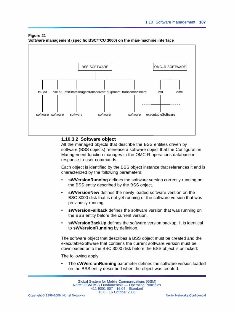
1.10 Software management 107
Figure 21Software management (specific BSC/TCU 3000) on the man-machine interface
1.10.3.2 Software objectAll the managed objects that describe the BSS entities driven bysoftware (BSS objects) reference a software object that the ConfigurationManagement function manages in the OMC-R operations database inresponse to user commands.
Each object is identified by the BSS object instance that references it and ischaracterized by the following parameters:
• sWVersionRunning defines the software version currently running onthe BSS entity described by the BSS object.
• sWVersionNew defines the newly loaded software version on theBSC 3000 disk that is not yet running or the software version that waspreviously running.
• sWVersionFallback defines the software version that was running onthe BSS entity before the current version.
• sWVersionBackUp defines the software version backup. It is identicalto sWVersionRunning by definition.
The software object that describes a BSS object must be created and theexecutableSoftware that contains the current software version must bedownloaded onto the BSC 3000 disk before the BSS object is unlocked:
The following apply:
• The sWVersionRunning parameter defines the software version loadedon the BSS entity described when the object was created.
Global System for Mobile Communications (GSM)Nortel GSM BSS Fundamentals — Operating Principles
411-9001-007 16.04 Standard16.0 16 October 2006
Copyright © 1999-2006, Nortel Networks Nortel Networks Confidential
.
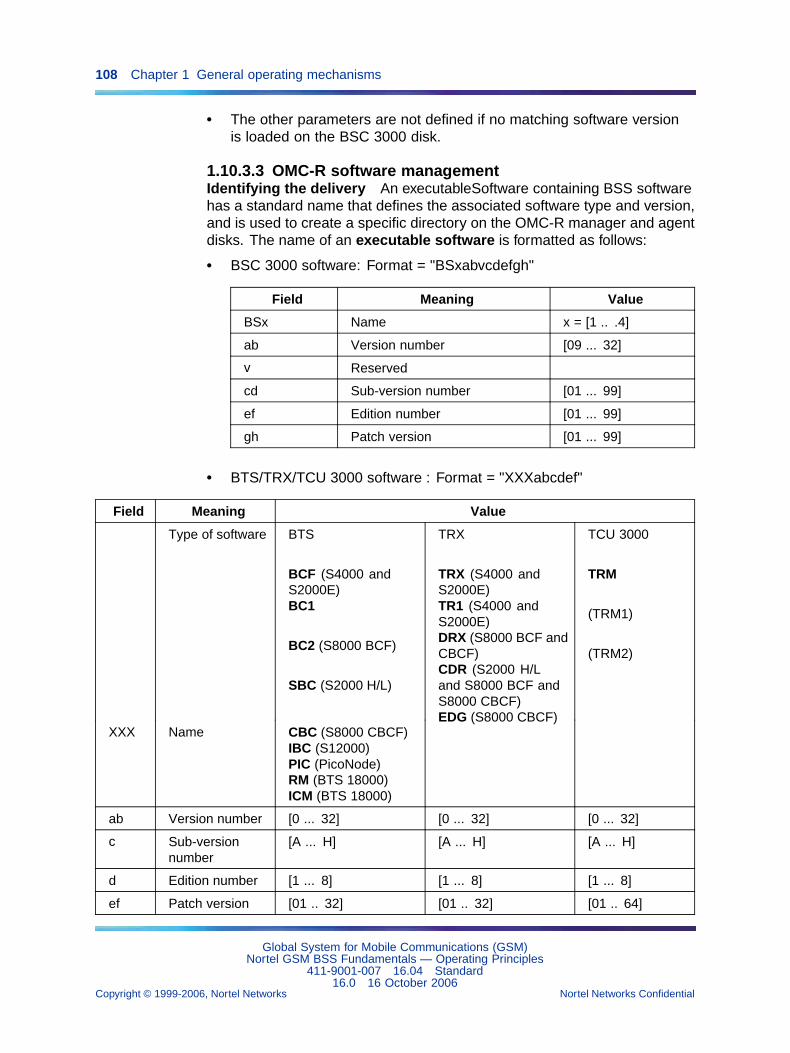
108 Chapter 1 General operating mechanisms
• The other parameters are not defined if no matching software versionis loaded on the BSC 3000 disk.
1.10.3.3 OMC-R software managementIdentifying the delivery An executableSoftware containing BSS softwarehas a standard name that defines the associated software type and version,and is used to create a specific directory on the OMC-R manager and agentdisks. The name of an executable software is formatted as follows:
• BSC 3000 software: Format = "BSxabvcdefgh"
Field Meaning Value
BSx Name x = [1 .. .4]
ab Version number [09 ... 32]
v Reserved
cd Sub-version number [01 ... 99]
ef Edition number [01 ... 99]
gh Patch version [01 ... 99]
• BTS/TRX/TCU 3000 software : Format = "XXXabcdef"
Field Meaning Value
Type of software BTS
BCF (S4000 andS2000E)BC1
BC2 (S8000 BCF)
SBC (S2000 H/L)
XXX Name CBC (S8000 CBCF)IBC (S12000)PIC (PicoNode)RM (BTS 18000)ICM (BTS 18000)
TRX
TRX (S4000 andS2000E)TR1 (S4000 andS2000E)DRX (S8000 BCF andCBCF)CDR (S2000 H/Land S8000 BCF andS8000 CBCF)EDG (S8000 CBCF)
TCU 3000
TRM
(TRM1)
(TRM2)
ab Version number [0 ... 32] [0 ... 32] [0 ... 32]
c Sub-versionnumber
[A ... H] [A ... H] [A ... H]
d Edition number [1 ... 8] [1 ... 8] [1 ... 8]
ef Patch version [01 .. 32] [01 .. 32] [01 .. 64]
Global System for Mobile Communications (GSM)Nortel GSM BSS Fundamentals — Operating Principles
411-9001-007 16.04 Standard16.0 16 October 2006
Copyright © 1999-2006, Nortel Networks Nortel Networks Confidential
.
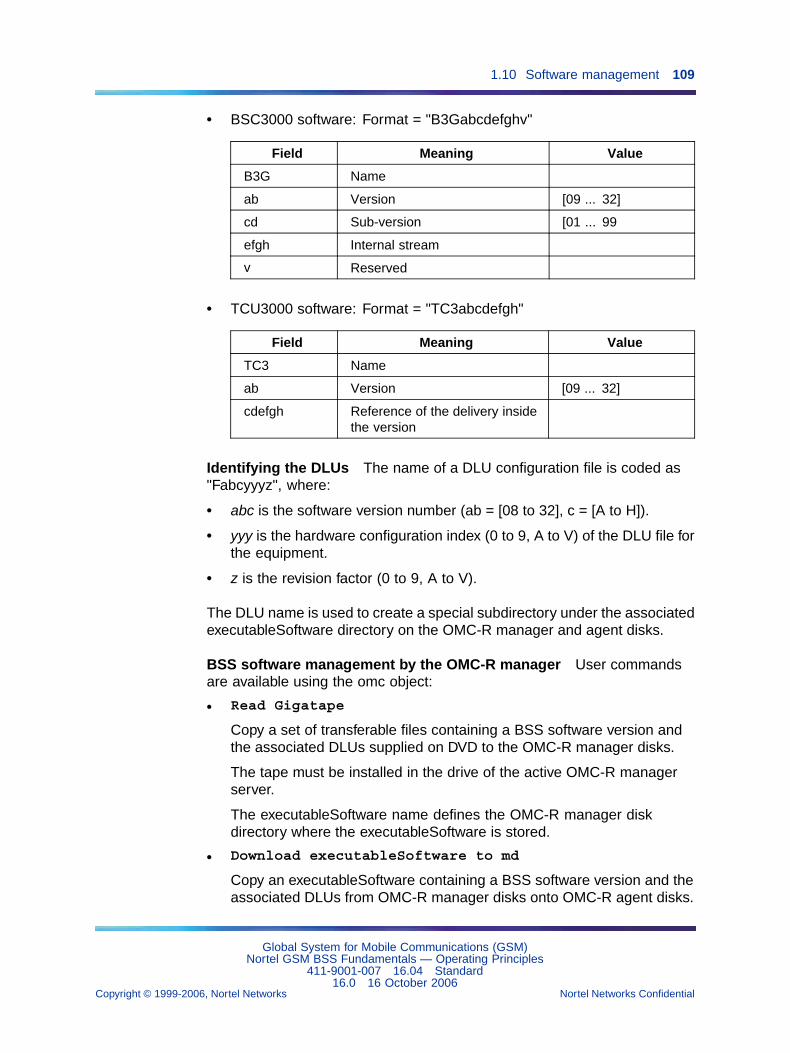
1.10 Software management 109
• BSC3000 software: Format = "B3Gabcdefghv"
Field Meaning Value
B3G Name
ab Version [09 ... 32]
cd Sub-version [01 ... 99
efgh Internal stream
v Reserved
• TCU3000 software: Format = "TC3abcdefgh"
Field Meaning Value
TC3 Name
ab Version [09 ... 32]
cdefgh Reference of the delivery insidethe version
Identifying the DLUs The name of a DLU configuration file is coded as"Fabcyyyz", where:
• abc is the software version number (ab = [08 to 32], c = [A to H]).
• yyy is the hardware configuration index (0 to 9, A to V) of the DLU file forthe equipment.
• z is the revision factor (0 to 9, A to V).
The DLU name is used to create a special subdirectory under the associatedexecutableSoftware directory on the OMC-R manager and agent disks.
BSS software management by the OMC-R manager User commandsare available using the omc object:
• Read Gigatape
Copy a set of transferable files containing a BSS software version andthe associated DLUs supplied on DVD to the OMC-R manager disks.
The tape must be installed in the drive of the active OMC-R managerserver.
The executableSoftware name defines the OMC-R manager diskdirectory where the executableSoftware is stored.
• Download executableSoftware to md
Copy an executableSoftware containing a BSS software version and theassociated DLUs from OMC-R manager disks onto OMC-R agent disks.
Global System for Mobile Communications (GSM)Nortel GSM BSS Fundamentals — Operating Principles
411-9001-007 16.04 Standard16.0 16 October 2006
Copyright © 1999-2006, Nortel Networks Nortel Networks Confidential
.
110 Chapter 1 General operating mechanisms
The executableSoftware to download is identified by name. The OMC-Ragent disk directory used to store the executableSoftware must becreated (see next Paragraph).
• Download and validate executableSoftware fromGigatape to md
Copy a set of transferable files containing a BSS software version andthe associated DLUs supplied on DVD to the OMC-R manager andagent disks, and validate the executableSoftware and DLU downloadingto disk.
This command enables to gather in one command the two previouslisted commands and the two creating commands described in thefollowing subparagraph.
• Delete executableSoftware
Delete an executableSoftware containing a BSS software version andthe associated DLUs from the OMC-R manager disks.
The executableSoftware is identified by name. The disk directory andall the files it contains are deleted.
• List executableSoftware
Display the list of delivery and associated DLUs created on the OMC-Rmanager disks. The OMC-R file manager supplies the information.
BSS software management by the OMC-R agent This function performstasks that may cause the OMC-R operations database (BDE) to be updated.
User commands are available using the md object as follows:
• Create executableSoftware dir
Create a directory on the OMC-R agent disks to store anexecutableSoftware containing a BSS software version and theassociated DLUs.
The directory is identified by the name of the executableSoftware due tobe downloaded next (see previous Paragraph):
— BSC 3000 software: The executableSoftware creation is not alreadyvalidated (see next).
— BCF software: If the executableSoftware creation is alreadyvalidated, the command can be used to associate more DLU files tothe executableSoftware.
— TRX/DRX and TCU 3000 software: The executableSoftware creationis not already validated (see next).
Global System for Mobile Communications (GSM)Nortel GSM BSS Fundamentals — Operating Principles
411-9001-007 16.04 Standard16.0 16 October 2006
Copyright © 1999-2006, Nortel Networks Nortel Networks Confidential
.
1.10 Software management 111
• Create executableSoftware
Validate an executableSoftware and associated DLU downloading tothe OMC-R agent disks (see previous Paragraph) to declare the BSSsoftware version to the OMC-R agent Software Management function.
If the command follows a Create executableSoftware dircommand used to associate more DLU files to the executableSoftware,downloading the executableSoftware to a BSC 3000 disk is forbiddenuntil the command is complete.
The directories corresponding to an executableSoftware delivery thatis not validated are automatically cleared and deleted when they aremore than three days old.
• Delete executable software
Delete an executableSoftware and the associated DLUs from theOMC-R agent disks. The disk directory and all the files it contains aredeleted.
The command is refused if the software version is referenced by asoftware object created in the BDE.
• List executableSoftware
Display the list of delivery and associated DLUs created on the OMC-Ragent disks. The OMC-R agent file manager supplies the information.
• "List (object instances referencing an executable-Software)
Display the list of software objects that reference a namedexecutableSoftware. The BDE supplies the information.
This command is a multiple-type command (scope & filter) and cannotbe accessed through a software object. It can be used before deletingan executableSoftware to check whether the executableSoftware isreferenced.
executableSoftware loading sequence BSS software loadingcommands must be entered in the following order to allow the OMC-RSoftware Management function to organize software versions correctly:
• Create executableSoftware dir (md object)
• Download executableSoftware to md (omc object)
• Create executableSoftware (md object)
After the system validates the last command, the executableSoftware iseffectively accepted by the OMC-R agent Software Management functionand can be downloaded to the BSC 3000 disk.
Global System for Mobile Communications (GSM)Nortel GSM BSS Fundamentals — Operating Principles
411-9001-007 16.04 Standard16.0 16 October 2006
Copyright © 1999-2006, Nortel Networks Nortel Networks Confidential
.
112 Chapter 1 General operating mechanisms
Consulting BSS and OMC-R software markers This function identifiesthe software applications currently running on BSS entities and on OMC-Rmanager and agent servers.
The marker files are stored in BSC 3000 and OMC-R server disk directories.A software application marker contains the following information:
• type (BSS entity or server) and name of the associated entity
• name and number of the application version (a version number isencoded in Vab_cd Enn format)
• a variable comments area, depending on the application type (usuallythe date when the application was generated)
Consulting BSS software markers The Display markers commandon any created software object provides the following information:
• software versions running on a BSC 3000, radio site BCF, radiotransceiver (TRX/DRX), or TCU 3000.
• PROM software versions in the same entities
• BSC 3000 prototype application database (BDA) configuration files
The command run invokes a reference file updated by the BSC 3000 thatcontains the list of BSS markers. The BSC 3000 then sends the informationto the OMC-R.
A reference file updating request is sent to the BSC 3000 and the resultinginformation is provided to users.
Consulting OMC-R software markers The Display markerscommand on the md object identifies the OMC-R agent active and passiveserver software applications.
The Display server markers and Display workstationmarkers commands on the omc object respectively identify the OMC-Rmanager active and passive server software applications, and the softwareapplications of a given workstation.
The file manager provides information on the application software that isrunning in the servers and workstations.
delivery downloading to the BSC 3000 The BSC 3000 delivery mustbe downloaded in /OMU/delivery/B3G/new. In fact, this directory containssix subdirectories which are AIX, AIN, BIN, BCN, BDA, APT; and thesubdirectories which correspond to the delivery are transferred to thatdelivery.
Global System for Mobile Communications (GSM)Nortel GSM BSS Fundamentals — Operating Principles
411-9001-007 16.04 Standard16.0 16 October 2006
Copyright © 1999-2006, Nortel Networks Nortel Networks Confidential
.
1.10 Software management 113
The TCU 3000 delivery must be downloaded in /OMU/delivery/TC3/new.
The BTS delivery must be downloaded in /OMU/delivery/BTS.
1.10.3.4 BSC 3000 disk configurationThe BSC 3000 houses two types of SCSI hard disks:
• the private disks
• the shared disks
Private disks Two private or local disks are used in a BSC 3000. Each ofthem is associated with one OMU module:
The partitions in each private disk are split up as follows:
• The root partition "/" contains the root directory, and AIX root file.
• The "/usr", "/var", "/tmp", "home" partitions contain the AIX runningsoftware. The sizes are derived from the AIX software needs.
• The "/tmp" file system partition is used also during upgrade to storethe copy of the package.
• The "/OMU_STORAGE" directory contains the applicative files storedon the OMU local and shared disk. The rw_ data directory is a"read/write" directory, used for important, long life applicative data. Thelog directory is used for short life data, which is temporarily stored onthe disk before being either sent to the OMC or erased by newer data.In case of disk space shortage on the log directory, the rw_datadirectory is not affected because they are on different partitions.
• The LOCAL_LOG "/OMU_STORAGE/log/local" partition contains thedump of the AIX board, because the OMU may not have access to theshared disk when restarting.
• The LOCAL_LOG "/OMU_STORAGE/rw_data/local" partition does notcontain anything.
• The LOCAL_LOG "/OMU_STORAGE/TREEn/local/usr" partitioncontains OAM platform and BaseOS application and tools.
Shared disks Two shared disks are used in a BSC 3000. Each of them ismanaged in a mirroring way for both OMU modules:
The partitions in each shared disk is split up as follows:
• Partition /OMU_STORAGE/rw_data/share, this partition contains filesthat are of long duration, compulsory, and whose size does not dependon the traffic or network configuration.
Global System for Mobile Communications (GSM)Nortel GSM BSS Fundamentals — Operating Principles
411-9001-007 16.04 Standard16.0 16 October 2006
Copyright © 1999-2006, Nortel Networks Nortel Networks Confidential
.
114 Chapter 1 General operating mechanisms
• Partition /OMU_STORAGE/SHARE, this partition contains the SW(switch) needed by the BSS, which includes all the former partitions(transited into directory only).
1.10.3.5 Downloading managementThis function is used to download new BSS software versions to the BSC3000 disks from the executableSoftware created and validated on theOMC-R agent disks.
User command The Download command is available for all createdsoftware objects.
Downloading consists of copying a BSS software version from the OMC-Ragent disks to the BSC 3000 disk related to the selected BSS object.
The user enters the executableSoftware name.
executableSoftware and associated DLU files are stored in dedicateddirectory(ies). The directory and subdirectories are identified from theinformation supplied by the executableSoftware.
Requirements The main requirements for the BSC 3000 are:
• No change software version command is executing on the selectedBSC 3000.
• No create or download new DLU file command is being processed forthe concerned executableSoftware.
• Up to five download commands that involve BSC 3000 can be executedat the same time by system users. After that, the OMC-R refuses thecommands.
The STF service provided by the OMC-R agent and the MTF service on theBSC 3000 manages the download command routine.Two download commands can be launched on BSC 3000 at the same time.
BSC 3000 software downloading The BSS software (BSC 3000, TCU3000 and BTS) is downloaded by the BSC 3000 from the OMC-R. For eachversion and edition, the complete BSS software is delivered on a CD-ROM.
It is sufficient for all upgrades from any authorized version (typically N-2and N-1 versions).
It is compressed and divided into several files in order to download only themodified files between two versions and to reduce as much as possiblethe duration of downloading.
Global System for Mobile Communications (GSM)Nortel GSM BSS Fundamentals — Operating Principles
411-9001-007 16.04 Standard16.0 16 October 2006
Copyright © 1999-2006, Nortel Networks Nortel Networks Confidential
.
1.10 Software management 115
The BSC 3000 stores two versions of the BSS software and the new versioncan be downloaded in the background without impacting BSC 3000 service.
Both the BSS software and the BSC 3000 OS can be downloaded in thebackground task, or installed locally from the TML through the Ethernet link.
There is no PROM memory on the BSC 3000 & TCU 3000 hardwaremodule, with the exception of the ATM_SW module (ATM switch).
All firmware is in flash EPROM and can be modified and downloadedremotely by the system.
The complete BSS software (BSC 3000, TCU 3000 and BTS) is downloadedfrom the OMC-R to the BSC 3000 through FTAM.
The OMC-R and BSC 3000 are connected through Ethernet and IPprotocols. The throughput is up to 10/100 Mbit/s (Ethernet standard) if theOMC is locally connected to the BSC 3000.
When the BSC 3000 is remote, a minimum throughput of 128 kbps isnecessary for the efficiency of OMC-R / BSC 3000 communication.
BTS and TCU 3000 software downloading by the BSC 3000
BTS software downloading The BSC 3000 can download ten BTS/TRXssimultaneously per TMU module. With ten "active" TMU modules, 100 BTSscan be downloaded simultaneously.
TCU 3000 software downloading TCU 3000 software is downloaded bythe BSC 3000. It is compressed and divided into several files, in order todownload only the modified files between two versions and to reduce thedownloading duration as much as possible.
The BSC 3000 stores two versions of TCU 3000 software.
The new version can be downloaded as a background task, withoutimpacting TCU 3000 service.
The TCU 3000 software can also be installed locally from the TML.
A set of LAPD connections is used for TCU 3000 management in normaloperation. These connections pre-empt (or wait for) time-slots used forcommunications. Two LAPD channels are managed per LSA module.
Download of a set of files (size of about 20 Mbytes per TCU 3000) lasts:
• with four LAPDs: about 20 minutes (requires a minimum of 2 LSAs)
• with eight LAPDs: about 10 minutes (requires a minimum of 3 LSAs)
Global System for Mobile Communications (GSM)Nortel GSM BSS Fundamentals — Operating Principles
411-9001-007 16.04 Standard16.0 16 October 2006
Copyright © 1999-2006, Nortel Networks Nortel Networks Confidential
.
116 Chapter 1 General operating mechanisms
Consequences
• BSC 3000 software:
— If the sWVersionNew or sWVersionFallback parameter wasdefined before downloading, the reference to the associatedsoftware version is deleted.
— The sWVersionNew parameter is defined with the newly loadedsoftware version.
— The sWVersionRunning is not changed.
— The sWVersionFallback is not defined.
• BCF, TRX/DRX, and TCU 3000 software:
— If the sWVersionNew parameter was defined before downloading,the reference to the associated software version is deleted.
— The sWVersionNew parameter is defined with the newly loadedsoftware version.
— The sWVersionRunning and sWVersionFallback parameters arenot changed.
DRX automatic downloading See Section 1.10.7 "Automaticdownloading of DRX software" (page 125).
1.10.3.6 BTS software background downloadingTwo phase upgrade process
With the feature “BSC3000 support of BTS SW background downloading(25316)”, introduced in V16.0, the upgrade process is done in two distinctphases: download and activation.
Without BTS background downloading, the time required to perform a start,a download, and a restart is much longer.
Download phase
BTS background downloading allows the software of the BTS to bedownloaded while the BTS is still running. The download phase can lastseveral hours but it does not impact the service. This phase can be doneoutside of the maintenance window.
Activation phase
The activation phase is similar to the pre-V16.0 activate procedure.However, it is much shorter since it no longer includes the time needed bythe download (which is done in a separate phase). This phase should bedone in the maintenance window.
User commands
Global System for Mobile Communications (GSM)Nortel GSM BSS Fundamentals — Operating Principles
411-9001-007 16.04 Standard16.0 16 October 2006
Copyright © 1999-2006, Nortel Networks Nortel Networks Confidential
.
1.10 Software management 117
OMC-R commands are provided to manage the upgrade process:
• The "BTS background download" command launches the softwaredownloading, which can be immediately followed by an activation.
• The "BTS background activate" command activates the new software.
• The "BTS background abort" command interrupts the softwaredownloading.
• The "BTS background download status" provides information onsoftware downloading.
1.10.3.7 Version managementThis function allows users to manage BSS software versions. The OMC-Roperations database (BDE) is updated.
User commands The user commands for changing software versions areavailable for all created software objects:
• The Activate new version command starts up a new softwareversion in a BSS entity.
• The Return to previous version command reactivates an oldsoftware version in a BSS entity.
Requirements
• General conditions:
— No BSC 3000 downloading command is executing on the selectedBSC 3000.
— The bsc e3 object is unlocked.
— Activate new version: A new software version is installed onthe BSC 3000 disk for the BSS object involved (the sWVersionNewparameter of the associated software object is defined).
— Return to previous version: An old software version isinstalled on the BSC 3000 disk for the BSS object involved (thesWVersionFallback parameter of the associated software objectis defined).
• BSC 3000 software:
— The BSC 3000 has two processing OMUs operating in duplex mode.
— Return to previous version: No new BSC 3000 softwareversion has been downloaded to the BSC 3000 disk since thecurrent version was activated (see previous Paragraph).
• BCF and TRX/DRX software:
Global System for Mobile Communications (GSM)Nortel GSM BSS Fundamentals — Operating Principles
411-9001-007 16.04 Standard16.0 16 October 2006
Copyright © 1999-2006, Nortel Networks Nortel Networks Confidential
.
118 Chapter 1 General operating mechanisms
— The concerned btsSiteManager or transceiverEquipment object islocked.
• TCU 3000 software:
— To optimize TCU 3000 software downloading time in remotetranscoding units, the system limits the number of operational TCU3000 software versions to two at any given time.
This limit must be respected. Before changing a software versionof this type, the procedure for checking and possibly upgradingsoftware must be performed (see NTP < 034 >).
After validating the command, the BSC 3000 loads the software version inthe BSS entity. The software type determines when the version is put inservice.
Starting up BSC 3000 software
BSC 3000 or TCU 3000 Cold Startup (BDA not built) The overall startupsequence describes how the BSC 3000 goes from its initial power-up state,with no software running, to a fully operational state where the applicationsare running and providing GSM service.
This type of startup is called dead office recovery and first needs the entireControl Node startup sequence to be performed.
The operator builds the network at OMC-R level and creates the BSC 3000logical object. He has to create the LSA-RC modules as well (with theirhardware positions).
As soon as the OMC-R/BSC 3000 link is established, the BSC 3000 sendsa notification indicating that an BDA build is requested.
Upon receipt of this notification, the OMC-R triggers the BDA build phase:
• The BDA is built on the active OMU.
• The "Build BDA N+1" upgrade feature is provided on the BSC 3000, asin a BSC 12000HC.
• This phase ends with the creation of the BDA logical objects followed bythe reception of a report build message.
Board startup: general behavior A module is said to be operationalwhen all of its boards are operational.
For each board, the startup sequence consists of three ordered steps:
• boot sequence
• platform initialization
• application initialization
Global System for Mobile Communications (GSM)Nortel GSM BSS Fundamentals — Operating Principles
411-9001-007 16.04 Standard16.0 16 October 2006
Copyright © 1999-2006, Nortel Networks Nortel Networks Confidential
.

1.10 Software management 119
Application initialization covers both the creation and initialization of theGSM BSC 3000 applications, this phase is managed in accordance with theBSC 3000 configuration and available resources.
Some boards are able to start autonomously, booting from non-volatilestorage, whereas others must wait as they require the services of anotherboard when operational.
The Control Node is operational once application initialization hascompleted successfully and the BSC 3000 is operational when the Controland Interface Nodes are operational.
BSC 3000 or TCU 3000 hot startup (BDA built) Since the BDA is alreadybuilt, we only have to check the hardware configuration consistency.
We must check that modules have not been introduced or removed whenthe BSC 3000 or the TCU 3000 was previously switched off.
The BSC 3000 and TCU 3000 will have the same behavior as for a coldstartup. The consistency between the new and the previous hardwareconfiguration is checked out at the OMC-R level.
Three things can happen:
• A module has been extracted: the corresponding object is deleted onthe MMI and in the BDA, and an alarm on the parent object indicatesthe suppression.
• A module has been plugged into a previously-free slot: thecorresponding object is automatically created on the MMI and in theBDA, and an alarm on the parent object indicates the creation.
• A module has been replaced by another one:
— The object corresponding to the replaced module is deleted on theMMI and in the BDA.
— The object corresponding to the newly inserted module is created onthe MMI and in the BDA.
— Alarms on the parent object indicate the suppression and thecreation.
Consequences The impact on software object parameters is the same,regardless of the new software type.
• Activate new version
— If the sWVersionFallback parameter was defined before thecommand, the reference to the associated software version isdeleted.
Global System for Mobile Communications (GSM)Nortel GSM BSS Fundamentals — Operating Principles
411-9001-007 16.04 Standard16.0 16 October 2006
Copyright © 1999-2006, Nortel Networks Nortel Networks Confidential
.
120 Chapter 1 General operating mechanisms
— The sWVersionRunning parameter is defined with the new softwareversion.
— The sWVersionFallback is defined with the previously runningsoftware version.
— The sWVersionNew parameter is not defined. The reference to theassociated software version is deleted.
• Return to previous version
— If the sWVersionNew was defined before the command, thereference to the associated software version is deleted.
— The sWVersionRunning parameter is defined with the restoredsoftware version.
— The sWVersionNew parameter is defined with the previouslyrunning version.
— The sWVersionFallback parameter is not defined. The reference tothe associated software version is deleted.
1.10.4 Consulting BSS software versionsThis function identifies the software versions available for the differenttypes of BSS entities. The OMC-R supplies the information recorded in itsoperations database.
The Display command on any created software object displays the objectparameters and the software versions it references.
1.10.5 BSC/OMC-R exchangesThe following figure illustrates the BSC/OMC-R exchanges related to usersoftware management commands.
The exchange with an OMC-R by a BSC 3000 or a BSC 12000HC isidentical. However, the EFT for the BSC 12000HC corresponds to the"executableSoftware" for the BSC 3000.
Global System for Mobile Communications (GSM)Nortel GSM BSS Fundamentals — Operating Principles
411-9001-007 16.04 Standard16.0 16 October 2006
Copyright © 1999-2006, Nortel Networks Nortel Networks Confidential
.
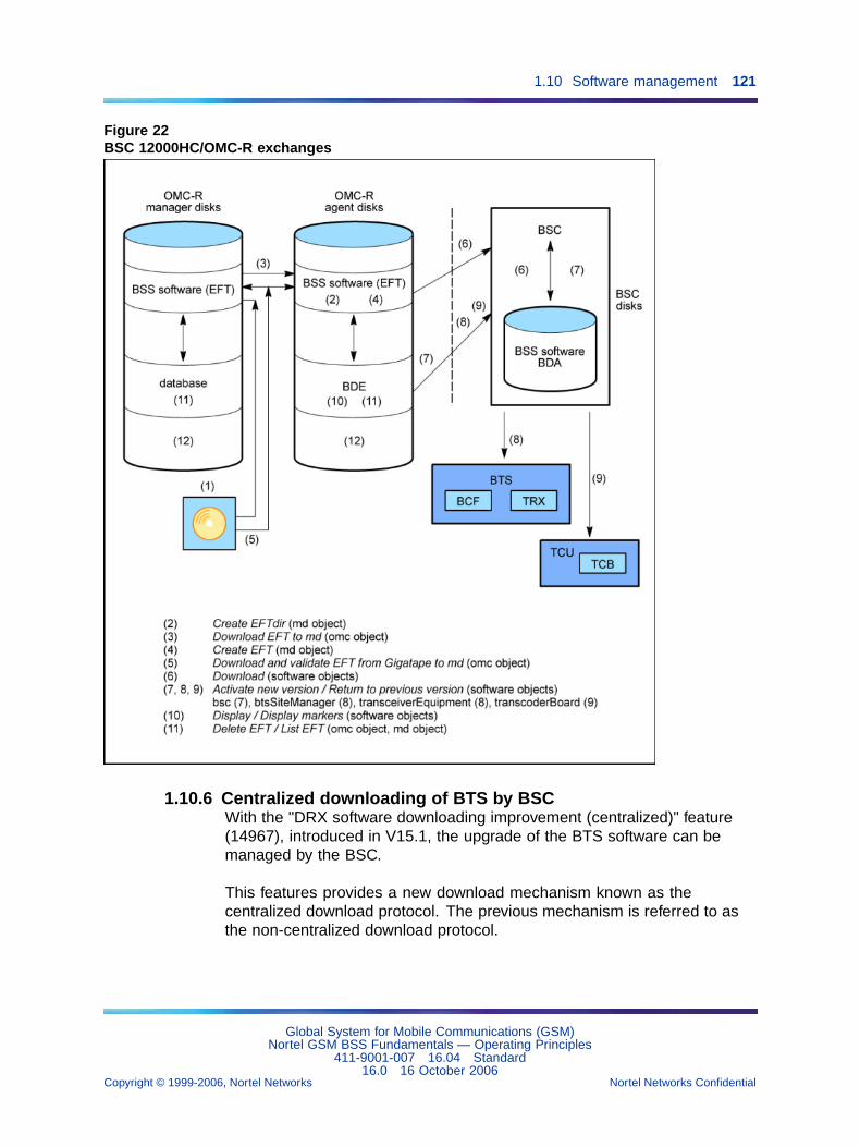
1.10 Software management 121
Figure 22BSC 12000HC/OMC-R exchanges
1.10.6 Centralized downloading of BTS by BSCWith the "DRX software downloading improvement (centralized)" feature(14967), introduced in V15.1, the upgrade of the BTS software can bemanaged by the BSC.
This features provides a new download mechanism known as thecentralized download protocol. The previous mechanism is referred to asthe non-centralized download protocol.
Global System for Mobile Communications (GSM)Nortel GSM BSS Fundamentals — Operating Principles
411-9001-007 16.04 Standard16.0 16 October 2006
Copyright © 1999-2006, Nortel Networks Nortel Networks Confidential
.
122 Chapter 1 General operating mechanisms
1.10.6.1 Centralized download protocolWith the centralized download protocol, the management of the softwaredownload is centralized in the Base Common Functions (BCF) of the BTS.The BSC gives the BCF a description of the software version(s) to bedownloaded. The BCF requests an Abis download of the necessary files.This avoids sending the same file several times on the Abis link. The BCFalso manages software duplication within the BTS. Since upgrades are donein parallel, the overall time required is reduced. The BSC periodically sendsa message to monitor progress and to detect changes in the downloadingstatus of the equipment.
Each DRX downloads its software directly from the BTS instead of from theassociated BSC. Consequently, the DRX software is transferred just oncefrom the BSC to the BTS (instead of being transferred for each DRX).
1.10.6.2 Non-centralized download protocolTo ensure compatibility with the existing non-centralized download protocol,and to permit the upgrade/downgrade of software versions that support thecentralized download protocol, the BTS informs the BSC of the downloadprotocols that it supports. The BTS can indicate that it supports one ofthe following:
• only the non-centralized protocol
• only the centralized protocol
• both protocols
If this field is not present in the message sent by the BTS, by default, theBSC selects the non-centralized download protocol. Existing BTSs remaincompatible with the non-centralized download protocol.
The non-COAM BTS (S4000) supports only the non-centralized downloadprotocol.
For operational reasons, some BTSs (as e-cell and BTS 18000) supportonly the new centralized download protocol.
For a BTS that supports both protocols, if the non-centralized downloadprotocol is selected by the BSC, the software download behavior is thesame as in V14.2, V14.3, and V15.0.
1.10.6.3 Improved BSC defense for centralized downloadingThe “BSC defense procedures for centralized downloading” feature (29213),introduced in V16.0, offers improved BSC defense procedures in the caseof centralized downloading.
Global System for Mobile Communications (GSM)Nortel GSM BSS Fundamentals — Operating Principles
411-9001-007 16.04 Standard16.0 16 October 2006
Copyright © 1999-2006, Nortel Networks Nortel Networks Confidential
.
1.10 Software management 123
The BSC and BTS exchange messages using the CSM (CentralizedSoftware Management) protocol. These messages are internal and arenot described here. However, since the message name may appear inthe Cause/Source associated with a Fault Number (for example, 1052 and1073), their names are listed below.
Names of CSM messages
The names CSM messages used are the following:
• CSM load container
• CSM load container ack/nack
• CSM software update init
• CSM software update control
• CSM software update report
• CSM software update abort
• CSM software update abort report
• CSM downloading start
• CSM downloading start ack/nack
• CSM downloading end
• CSM downloading end ack/nack
• CSM load init
• CSM load init ack/nack
• CSM load data
• CSM load data ack/nack
• CSM load end
• CSM load end ack/nack
• CSM flash activation (only used in offline mode)
• Extended CSM flash activation (only used in background mode)
• CSM flash activation report
Stages of an Abis download
The download of a file on the Abis takes place in three stages:
• CSM Load init procedure
• CSM Load data procedure
• CSM Load end procedure
Global System for Mobile Communications (GSM)Nortel GSM BSS Fundamentals — Operating Principles
411-9001-007 16.04 Standard16.0 16 October 2006
Copyright © 1999-2006, Nortel Networks Nortel Networks Confidential
.
124 Chapter 1 General operating mechanisms
CSM Load init procedure
This sequence permits the BSC and the BTS equipment to initiate thedownload of a file and establish the characteristics of the data transfer.
The BSC proposes the parameters of the download taking account of itsown capacity.
The equipment confirms the parameters of the download, taking accountof its own capacity and that of the BSC. The equipment can modify someparameters without exceeding the maximum or minimum limits proposedby the BSC.
CSM Load data procedure
The download takes place as follows:
1. The BSC sends a CSM load data message within the limit of the sendingbuffer size (a download parameter).
2. The equipment (BCF or TRX) acknowledges by sending a CSM loaddata ack message taking account of the limit of the acknowledgementbuffer size (a download parameter).
The CSM load data messages are numbered.
In case of loss of a message, the equipment sends a CSM load data nackcontaining the number of the incomplete window. The BSC then resumesemission of CSM load data messages at the beginning of the windowcontaining the unreceived block.
In case of non-receipt of a CSM load data ack, the BSC resumesthe emission of CSM load data messages at the beginning of theunacknowledged window.
This mechanism of resuming is activated several times before aborting thedownload (so as to be able to resume the download of a file in progressafter a loss of PCM).
CSM Load end procedure
The BSC sends a CSM downloading end message and the equipmentreplies with a CSM downloading end ack message.
BSC defense mechanisms
The following enhanced BSC defense mechanisms are implemented inV16.0. These mechanisms are used on:
• receipt of BTS error report
• non-response of BTS to a CSM message sent by BSC
Global System for Mobile Communications (GSM)Nortel GSM BSS Fundamentals — Operating Principles
411-9001-007 16.04 Standard16.0 16 October 2006
Copyright © 1999-2006, Nortel Networks Nortel Networks Confidential
.
1.10 Software management 125
When there is a no response from the BTS, a notification 1059 (with thecause “no response from BTS”) is sent to operator. In the case of offlinedownloading, this notification includes the CSM message sent by the BSC.
The BSC uses internal counters to count the number of attempts atdownloading and the number of attempts at sending of a message. TheBSC takes account of these counters in deciding the defense action it takes.
The BSC defense actions are:
• Retry the download
• Stop the download
Retry the download (also known as “retry_dwld”)
1. Emit a Fault number 1073 with the cause related to the problemdetected.
2. Send a CSM software update abort message (if the report is OK, NOK,or if there is no response, the following actions will be the same).
3. Send a RESET message (only for offline downloading, not forbackground downloading).
4. Wait for a TBOOT.
5. Retry the session (by sending a new CSM software update initmessage).
Stop the download (also known as “stop_dwld”):
1. Send a CSM software update abort message (if the report is OK, NOK,or if there is no response, the following actions will be the same),
2. Send a RESET message (only for offline downloading, not forbackground downloading),
3. Emit a Fault number 1052 with the cause related to the problemdetected.
1.10.7 Automatic downloading of DRX softwareEach of type of DRX hardware: DRX, eDRX, ND3, etc. has its own softwareload (EFT, catalog file) and a hardware reference. If one type of DRX isreplaced by another type, the operator must download the appropriatesoftware for the new type.
1.10.7.1 Downloading procedureThe "S8000 DRX-EDGE DRX automatic downloading on BSC 3000" feature(27633), introduced in V15.1, automatically finds the EFT on the OMC-Rand downloads it.
Global System for Mobile Communications (GSM)Nortel GSM BSS Fundamentals — Operating Principles
411-9001-007 16.04 Standard16.0 16 October 2006
Copyright © 1999-2006, Nortel Networks Nortel Networks Confidential
.
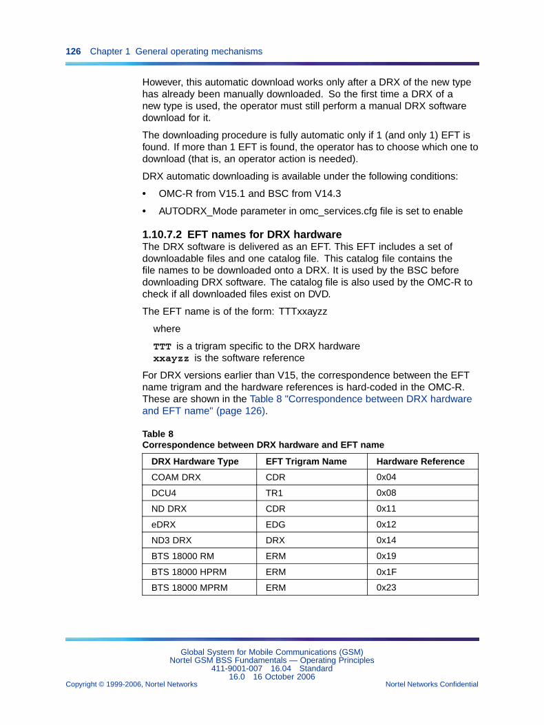
126 Chapter 1 General operating mechanisms
However, this automatic download works only after a DRX of the new typehas already been manually downloaded. So the first time a DRX of anew type is used, the operator must still perform a manual DRX softwaredownload for it.
The downloading procedure is fully automatic only if 1 (and only 1) EFT isfound. If more than 1 EFT is found, the operator has to choose which one todownload (that is, an operator action is needed).
DRX automatic downloading is available under the following conditions:
• OMC-R from V15.1 and BSC from V14.3
• AUTODRX_Mode parameter in omc_services.cfg file is set to enable
1.10.7.2 EFT names for DRX hardwareThe DRX software is delivered as an EFT. This EFT includes a set ofdownloadable files and one catalog file. This catalog file contains thefile names to be downloaded onto a DRX. It is used by the BSC beforedownloading DRX software. The catalog file is also used by the OMC-R tocheck if all downloaded files exist on DVD.
The EFT name is of the form: TTTxxayzz
where
TTT is a trigram specific to the DRX hardwarexxayzz is the software reference
For DRX versions earlier than V15, the correspondence between the EFTname trigram and the hardware references is hard-coded in the OMC-R.These are shown in the Table 8 "Correspondence between DRX hardwareand EFT name" (page 126).
Table 8Correspondence between DRX hardware and EFT name
DRX Hardware Type EFT Trigram Name Hardware Reference
COAM DRX CDR 0x04
DCU4 TR1 0x08
ND DRX CDR 0x11
eDRX EDG 0x12
ND3 DRX DRX 0x14
BTS 18000 RM ERM 0x19
BTS 18000 HPRM ERM 0x1F
BTS 18000 MPRM ERM 0x23
Global System for Mobile Communications (GSM)Nortel GSM BSS Fundamentals — Operating Principles
411-9001-007 16.04 Standard16.0 16 October 2006
Copyright © 1999-2006, Nortel Networks Nortel Networks Confidential
.
1.11 SMS-CB management 127
The catalog file contains an internal table that contains hardware masksand hardware references. The hardware masks list the features availablefor each DRX hardware type supported by the catalog file. The hardwarereferences identify the types of BTS hardware supported by the catalog file.Column 3 of Table 8 "Correspondence between DRX hardware and EFTname" (page 126) lists these hardware references for the case of DRXhardware.
Any values of hardware references other than those shown in the table arenot treated by the DRX automatic downloading feature.
For DRX versions later than V15, the OMC-R manages a dynamic table thatgives the correspondence between the EFT name trigram and the hardwarereferences.
Each time a V15 EFT is downloaded on the OMC-R, the OMC-R:
• analyses the EFT
• opens the catalog file to read the hardware references
• updates its correspondence table with the EFT trigram/hardwarereferences
1.10.8 Improved upgrade performanceThe upgrade improvements, introduced in V15.1, reduce the amount oftime required for an upgrade. These improvements apply to upgradingfrom V15.1.
The improvements include:
• upgrading components in parallel instead serially where possible (CNand IN)
• verifying that the component status is compatible with upgrade beforestarting the upgrade (CC1 reset)
• improving the flash upgrade protocol (OMU)
1.11 SMS-CB management1.11.1 Overview
The OMC-R Short Message Service - Cell Broadcast (SMS-CB) functionallows users to broadcast short messages to a preselected list of BSCsand BTSs.
This service allows users to manage short messages on the OMC-R andsend the orders to the BSSs to broadcast the messages to mobiles. It hastwo functions:
• short message management
• message broadcast management
Global System for Mobile Communications (GSM)Nortel GSM BSS Fundamentals — Operating Principles
411-9001-007 16.04 Standard16.0 16 October 2006
Copyright © 1999-2006, Nortel Networks Nortel Networks Confidential
.
128 Chapter 1 General operating mechanisms
1.11.2 PrinciplesShort messages are defined on the OMC-R. They are managed locallyby the OMC-R manager and recorded as short message objects in itsdatabase.
Each short message is identified by a specific name allocated by the user.The name is unique on the OMC-R.
The messages are broadcast on a Cell Broadcast control CHannel (CBCH):
• A short message broadcast in unacknowledged mode is characterizedby an identifier specified by the user and a unique serial numberallocated by the OMC-R at the start of the broadcast. It allows themobiles to identify the message and ignore a previously receivedmessage.
• A short message broadcast can be started in any number of cells,possibly belonging to different BSSs, at the same time.
• Five short messages at a time can be broadcast in a cell, whateverthe BSS version is.
System users can access all the short messages, regardless of their owner.
Each BSC that controls the cells where a message is being broadcast sendsthe selected message to the BTSs covering the cells at regular intervalsaccording to the repetition rate defined by the user.
The messages broadcast in a BSS are stored in a duplex partition on theBSC disk. In case of BSC restart or switchover, short message broadcastsare not interrupted.
Short message broadcasts in a BSS are automatically interrupted if theBSC application database is reset by a user command. The broadcast mustbe restarted when the database is rebuilt.
Short message broadcasts in a radio cell are aborted if the broadcastconditions in the cell are not satisfied (CBCH deleted).
1.11.3 Message managementThe Message Management subfunction of the SMS-CB service allowsusers to do the following:
• create, modify, and delete short messages
• display created short message characteristics
• list the short messages created on the OMC-R
Global System for Mobile Communications (GSM)Nortel GSM BSS Fundamentals — Operating Principles
411-9001-007 16.04 Standard16.0 16 October 2006
Copyright © 1999-2006, Nortel Networks Nortel Networks Confidential
.
1.11 SMS-CB management 129
1.11.3.1 Short message characteristicsA short message is identified by a name defined by the user who creates itand is unique on the OMC-R. This information is not forwarded to the BSCs.
The message parameters are as follows:
• message language (English, French, Spanish, etc.)
• message text
• message identifier
• optional comments
The short message characteristics (including its name) can be changedduring an ongoing broadcast. The new data are only implemented when theshort message broadcast restarts.
A short message cannot be deleted during an ongoing broadcast.
1.11.3.2 Editing short messagesUsers can change the name of a short message created on the OMC-Rwith the Rename command.
The Display command displays short message characteristics.
The multiple-type List command or the Line mode List shortmessages command allows users to display the list of short messagescreated on the OMC-R (only the message names and comments, if any,are supplied).
1.11.3.3 Managing the SMS-CB alphabetThe Man-Machine interface allows the user to use any SMS-CB alphabetcharacter, as defined in the GSM 03.41 standard, version 4.4.0, in order towrite a short message text.
The following apply:
• ASCII characters that can be directly entered from the keyboard areseized either by pressing the corresponding key or by typing the ‘character followed by the character hexadecimal value.
• Characters that cannot be directly entered from the keyboard are seizedin one of the following ways:
— type the ’character followed by the character hexadecimal value
— for some of them, use the compose key followed by a specialsequence of keys
The Man-Machine interface checks that all characters seized by the userare part of the SMS-CB alphabet.
Global System for Mobile Communications (GSM)Nortel GSM BSS Fundamentals — Operating Principles
411-9001-007 16.04 Standard16.0 16 October 2006
Copyright © 1999-2006, Nortel Networks Nortel Networks Confidential
.
130 Chapter 1 General operating mechanisms
In the dialogue window, the short message text definition field includes adialogue zone where the text is displayed as it is seized (ASCII display whenthe seizure is direct or the compose key is used, or hexadecimal displaywhen the hexadecimal value is entered), and a zone where the hexadecimalvalues of all entered characters are displayed.
On-line help provides the correspondence between all SMS-CB alphabetcharacters and their hexadecimal codes.
Starting from V14.2, customers can access the binary data format inaddition to the existing ASCII format.
The characters of the 7-bits coded SMS-CB alphabet and the specialsequences of keys used with the compose key are detailed in the NTP<130> (Chapter describing the SMS-CB management commands).
1.11.4 Broadcast managementThe Broadcast Management subfunction of the SMS-CB service allowsusers to do the following:
• start and stop short message broadcast
• display information on a short message broadcast
1.11.4.1 RequirementsThe bts and bsc objects concerned by an unacknowledged, short messagebroadcast must be created on the OMC-R.
No more than five short messages at a time can be broadcast in a cell.
The messages are broadcast to mobiles on a specific radio channel, theCBCH. This channel must be defined for any cell concerned by a broadcastcommand or the OMC-R refuses the request for that cell.
Unacknowledged short messages can only be broadcast in a BSS when theBSC application database (BDA) is built or the OMC-R refuses the request.
1.11.4.2 Starting a broadcastThe Start broadcast command on a short message object starts agiven short message broadcast in a number of cells that may belong todifferent BSSs.
The user specifies the following:
• name of the short message to broadcast
• periodicity (repetition rate). The authorized values are as follows: 2 s,30 s (default), 1 mn, 2 mn, 4 mn, 8 mn, 16 mn, and 32 mn
Global System for Mobile Communications (GSM)Nortel GSM BSS Fundamentals — Operating Principles
411-9001-007 16.04 Standard16.0 16 October 2006
Copyright © 1999-2006, Nortel Networks Nortel Networks Confidential
.
1.11 SMS-CB management 131
• cells concerned (list of bts objects). Each cell is identified by a (bsc,btsSiteManager, bts) combination or by a list of BSCs that identifies thecell on the OMC-R.
The OMC-R manager searches for an available serial number in the rangeof values [16 to 16368] to allocate to the broadcast:
• The search starts in ascending order from the last allocated serialnumber, plus 16.
• If the maximum number is reached, the search continues from theminimum value [16].
• The first available serial number is allocated to the broadcast andrecorded.
• If no serial number is available, the broadcast request is refused andthe user is informed.
If the broadcast command is validated, the system response to the usercommand contains the serial number allocated to the broadcast.
If the short message broadcast in a cell is refused, the user is informed ofthe cause. This does not prevent the broadcast in the other cells in the list.
Choosing a broadcasting repetition rate of 2 seconds forbids othermessages to be broadcast in the concerned cell at the same time; thisis due to the maximum capacity of the Air interface which is limited toone message every two seconds. Since the OMC-R does not check thatconstraint, the user is not warned.
1.11.4.3 Broadcast scheduling in the BSSWhen several messages are scheduled for broadcasting at the same time,the BSC has to choose which message should be broadcast first.
In case of broadcasting conflict, the following rules apply:
• If two messages are scheduled for broadcasting in the same slot, theBSC will favor the message with the longer repetition rate.
• If two messages with the same repetition rate are scheduled forbroadcasting in the same slot, the BSC will favor the message that hasnot been broadcast the most recently (this allows to alternate betweenthe two messages).
1.11.4.4 Stopping a broadcastA broadcast can be stopped in two ways.
• Stop broadcast command on a bts object
Global System for Mobile Communications (GSM)Nortel GSM BSS Fundamentals — Operating Principles
411-9001-007 16.04 Standard16.0 16 October 2006
Copyright © 1999-2006, Nortel Networks Nortel Networks Confidential
.
132 Chapter 1 General operating mechanisms
This command stops short message broadcasting in the specified cell.Once the command is validated, the system response to the commandcontains the list of the short messages that were being broadcast inthe cell.
• Stop broadcast command on a short message object
This command stops the specified short message broadcast in allthe cells where it is broadcast. Once the command is validated, thesystem response to the command contains the list of the cells wherethe broadcast has been stopped.
1.11.4.5 Displaying broadcast characteristicsUsers can choose between the following commands:
• Display broadcast characteristics on a bts object displaysthe characteristics of ongoing short message broadcasts in a specifiedcell. For each ongoing message broadcast in the cell, the OMC-Rsupplies the following information:
— short message name and characteristics
— broadcast periodicity (repetition rate)
— serial number allocated to the broadcast
• Display broadcast characteristics on a short message objectdisplays the characteristics of a specified short message broadcast innetwork cells. The short message is identified by name. The OMC-Rsupplies the following information:
— short message characteristics
— for each cell broadcasting the short message:
– (bsc, btsSiteManager, bts) combination identifying the cell
– broadcast periodicity (repetition rate)
– serial number allocated to the broadcast
1.12 Performance management1.12.1 Overview
1.12.1.1 PrinciplesThe OMC-R Performance Management function analyzes the informationon operating conditions supplied by the OMC-R manager and connectedworkstations on one hand and by the OMC-R agent and the BSSs it controlson the other hand, to provide users with network monitoring and archivingfacilities.
Global System for Mobile Communications (GSM)Nortel GSM BSS Fundamentals — Operating Principles
411-9001-007 16.04 Standard16.0 16 October 2006
Copyright © 1999-2006, Nortel Networks Nortel Networks Confidential
.
1.12 Performance management 133
The raw measurements obtained from the OMC-R agent and BSSobservations (for GSM and GPRS services) allow users to monitor networkand management system performances and intervene on operatingconditions.
The Performance Management function does the following:
• manages the observations:
— for the OMC-R agent and BSSs, starts (create mdScanner objects),stops (delete these objects or automatic abort by the system), andcontrols (display and set created objects)
— collects raw measurements (raw counters) from the OMC-Rmanager and connected workstations on one hand (permanentobservation) and from the BSSs and the OMC-R agent on the otherhand (permanent and temporary observations)
— calculates performance indicators (synthetic counters) in real timefrom raw counters (manager, md, BSS permanent, real time andpcuSN).
The operator can create synthetic counters for the observationssupporting this function (i.e. permanent observation: OFS, OGS,ORT, ODIAG and OPCUSN).
— detects BSS and OMC-R agent permanent observation raw counterthreshold crossing at OMC-R agent level
— detects BSS, MD-R, PCUSN and Manager synthetic counterthreshold crossing at OMC-R manager level
• manages Call tracing and Call path tracing functions:
— starts (create traceControl and callPathTrace objects), stops (deleteor lock these objects), and controls (display and set created objects)
— collects trace messages from the BSS tracing functions
• stores observation records in specific files on the OMC-R agent andmanager disks
• stores trace records in specific files on the OMC-R agent disks
• makes available, on request, permanent and temporary observationreports (raw, custom, daily, and busiest day of the month)
• archives information at OMC-R manager level on removable magneticcartridges that allow users to study the information at a later time toimprove the quality of service and optimize cost effectiveness
• collects radio distribution files from the BSC and makes them availableon SDO in XML format
Global System for Mobile Communications (GSM)Nortel GSM BSS Fundamentals — Operating Principles
411-9001-007 16.04 Standard16.0 16 October 2006
Copyright © 1999-2006, Nortel Networks Nortel Networks Confidential
.
134 Chapter 1 General operating mechanisms
• collects call drop files from the BSC and makes them available on SDOin XML format
• collects interference matrix files from the BSC and makes them availableon SDO in XML format
1.12.1.2 Managed objectsManaged objects at OMC-R agent level The objects managed atOMC-R agent level fall into the following categories:
• The mdScanner objects created by users stop and start the OMC-Ragent permanent observation and the BSS permanent and temporaryobservations.
• The traceControl and callPathTrace objects created by users stop andstart the BSS Call tracing (traceControl objects) and Call path tracing(callPathTrace objects) functions.
• The associated log objects created by the OMC-R agent defineassociated message storage conditions on the OMC-R agent disks:a current observation log is partnered with each created mdScannerobject (not including the instrument panel), a current trace log ispartnered with each created traceControl or callPathTrace object, arestored message log is created when observation or trace files arerestored to OMC-R agent disks.
• The efd objects of "obs" and "trace" types allow users to filter theobservation or trace message feedback to the OMC-R manager.
• The mdWarning objects describe the conditions in which alarms relatedto "observation counter threshold crossing" and "excessive softwareapplication error rate" notifications are issued by the OMC-R agent.
• The mdScanReportRecord objects store the temporary observationdata record in an observation log.
• The observationFileReadyRecord objects store the filename ofpermanent observation data record in an observation log.
• The traceLogRecord objects describes the call tracing data recordformat in a trace log for the priority traces collected by the Call tracingfunction.
• The traceFileReadyRecord objects describe the names of the fileswhere the records of non--priority traces collected by the Call tracingand Call path tracing functions are stored.
All these objects are functional objects that depend on the md object. Theycan be accessed through the related managed object (such as bsc, bts, md,etc.). They have numerous instances.
Global System for Mobile Communications (GSM)Nortel GSM BSS Fundamentals — Operating Principles
411-9001-007 16.04 Standard16.0 16 October 2006
Copyright © 1999-2006, Nortel Networks Nortel Networks Confidential
.
1.12 Performance management 135
Managed objects at OMC-R manager level The MMI omc object allowsusers to consult OMC-R manager and connected workstation observationreports.
1.12.1.3 Mechanisms of observation.The mechanism of observation can be subdivided as follows:
• Permanent observation : specific mechanisms
— Real time observation (ORT)
— The general statistic permanent observation (OGS)
This observation must allow the realization of daily statistics.
— The fast statistic observation (OFS)
This observation must allow the realization of hourly statistics.
— Diagnostic permanent observation (ODIAG)
This observation must allow the observation and the control of networkor the investigation on the bad function. The diagnostic of observation isactivated on cells selected or preselected during a time defines.
• Temporary observation (specific to the BSC 12000HC)
The temporary observations types available depend on BSS release.
— Abis Interface temporary observation
— Interference temporary observation,
— SS7 link temporary observation
BSS permanent observation The BSS permanent observation is startedon user request and covers a large number of BSS counters that areperiodically sent to the OMC-R agent for forwarding to the OMC-R manager.
The data are stored. They are displayed and backed up on user request.
Permanent md observation The permanent md observation is started onuser request and involves all the OMC-R agent counters that are periodicallyread by the OMC-R agent and forwarded to the OMC-R manager.
The data are stored. They are displayed and backed up on user request.
Permanent manager observation The permanent manager observationis automatically started when the OMC-R is started up and is not managedby users. It involves all the OMC-R manager and connected workstationcounters that are periodically read and collected by the OMC-R manager.
Global System for Mobile Communications (GSM)Nortel GSM BSS Fundamentals — Operating Principles
411-9001-007 16.04 Standard16.0 16 October 2006
Copyright © 1999-2006, Nortel Networks Nortel Networks Confidential
.
136 Chapter 1 General operating mechanisms
The data are stored. They are displayed and backed up on user request.
Real time observation The BSC real time observation is a subset of theBSS permanent observation. Its content is informative and is periodicallyforwarded to the OMC-R agent.
The last received message can be displayed in real time.
Temporary observations (specific for the BSC 12000HC) A temporaryobservation is started on user request and involves a large number ofcounters that supply indications on the operating conditions of BSS entities(physical or logical) that are not regularly monitored.
BSS counters are periodically sent to the OMC-R agent for forwarding tothe OMC-R manager.
The data are used for in--depth analysis of permanent observations and arestored. They are displayed and backed up on user request.
1.12.1.4 Observation time parametersObservation time parameters are as follows:
• periodicity of BSS counter collection
The mdGranularityPeriod parameters of the mdScanner objectsdescribing the BSS permanent, performance monitor, and temporaryobservations define the period at which the OMC-R agent collects theBSS counters.
These periodicities are set by the user with different values accordingto the observed BSC and observation type. The BSS permanent andperformance monitor observation parameters can be modified.
• periodicity of OMC-R agent counter collection
The mdGranularityPeriod parameter of the mdScanner object describingthe permanent md observation defines the period at which the OMC-Ragent reads its own counters.
The default value of this parameter is 5 minutes but can be modified.
• periodicity of OMC-R manager counter collection
The period at which the OMC-R manager reads its own counters andthose of the connected workstations is defined in the static configurationand cannot be modified.
• temporary observation run times
The stopTime parameter of mdScanner objects describing temporaryobservations defines the corresponding observation run time.
Global System for Mobile Communications (GSM)Nortel GSM BSS Fundamentals — Operating Principles
411-9001-007 16.04 Standard16.0 16 October 2006
Copyright © 1999-2006, Nortel Networks Nortel Networks Confidential
.
1.12 Performance management 137
Run times are set by the user with different values according to theobservation. They cannot be modified and are limited to 24 hours.
1.12.1.5 Observation countersThere are two types of observation counters:
• Raw counters contain the raw measurements from the BSS (GSMand GPRS services) or OMC-R agent and are divided into cumulativecounters, load counters, and value counters (BSS).
• Synthetic counters contain the data calculated from raw counter dataor other synthetic counter data. The calculation formulas are definedin configuration files.
These counters allow users to perform an in--depth analysis ofnetwork operating conditions. They are unique to permanent manager,permanent md, BSS permanent, pcuSN and Performance Monitorobservations.
Some totals can be calculated in time (custom totals, daily totals) and inspace (for example, totals calculated on all cells of a BSS).
1.12.1.6 Identifying the observation countersThe OMC-R identifies each observation counter by a Q3 name and title thatidentify the counter in a defined class/type:
• class = raw, synthetic
• type = BSS permanent (OFS and OGS), Real Time (ORT), temporary(including ODIAG), permanent md, permanent manager and PCUSN
A raw counter contains the raw data measured by the BSS entity, whereas asynthetic counter contains the processed results calculated by the OMC-Rfrom raw measurements or synthetic calculations.
NTPs < 125 > and < 133 > detail the observation counters and theirfunctions.
1.12.2 Permanent observations1.12.2.1 Permanent observation management
• BSS permanent observation
A BSS permanent observation must be activated when the BSS isstarted up for the first time by creating an mdScanner object. Theobservation is stopped by deleting the mdScanner object but this isnot recommended.
The Display command on the object allows users to see whetherthe observation is running, check the counter collection period
Global System for Mobile Communications (GSM)Nortel GSM BSS Fundamentals — Operating Principles
411-9001-007 16.04 Standard16.0 16 October 2006
Copyright © 1999-2006, Nortel Networks Nortel Networks Confidential
.
138 Chapter 1 General operating mechanisms
(mdGranularityPeriod parameter), and obtain other characteristics. Thecollection period can be changed while the observation is running.
A BSS permanent observation processes raw counters collected by theBSS and synthetic counters computed by the OMC-R agent.
• Permanent md observation
The OMC-R agent permanent observation starts automatically when thesystem is initialized and cannot be stopped. When the mdScanner objectthat describes the observation is created, the OMC-R agent immediatelystarts collecting and forwarding its own counters to the OMC-R manager.
The Display command on the object allows users to check thecounter collection period (mdGranularityPeriod parameter), and obtainother characteristics. The collection period can be changed when thecorresponding mdScanner object is created.
The permanent md observation processes raw counters collected onthe OMC-R agent active server and synthetic counters computed bythe OMC-R manager.
• Permanent manager observation
The OMC-R manager permanent observation starts automaticallywhen the system is initialized and cannot be stopped. When a newworkstation is connected, its own counters are automatically collected.
The permanent manager observation processes raw counters collectedon the active OMC-R manager and connected workstation servers, andsynthetic counters computed by the OMC-R manager.
1.12.2.2 Permanent observation periodsThe mdGranularityPeriod periods are used to manage this observation.
Their characteristics are the following:
• A BSS permanent observation collection period may vary independentlyof the permanent observation collection periods of other BSSs controlledby the OMC-R agent. Each period is synchronized on the BSC referencetime stamp.
Global System for Mobile Communications (GSM)Nortel GSM BSS Fundamentals — Operating Principles
411-9001-007 16.04 Standard16.0 16 October 2006
Copyright © 1999-2006, Nortel Networks Nortel Networks Confidential
.
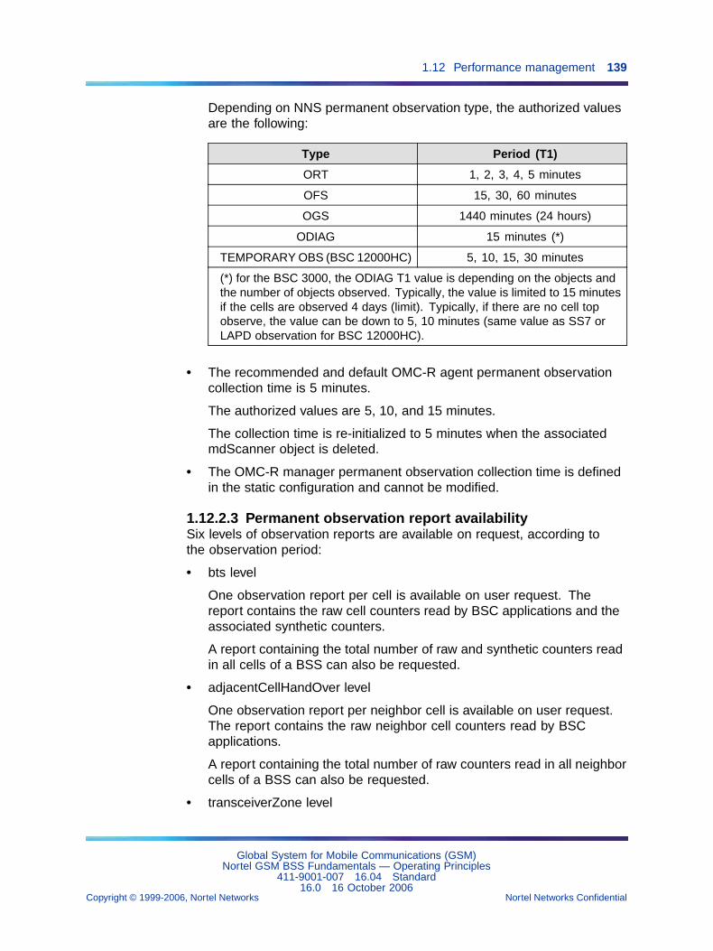
1.12 Performance management 139
Depending on NNS permanent observation type, the authorized valuesare the following:
Type Period (T1)
ORT 1, 2, 3, 4, 5 minutes
OFS 15, 30, 60 minutes
OGS 1440 minutes (24 hours)
ODIAG 15 minutes (*)
TEMPORARY OBS (BSC 12000HC) 5, 10, 15, 30 minutes
(*) for the BSC 3000, the ODIAG T1 value is depending on the objects andthe number of objects observed. Typically, the value is limited to 15 minutesif the cells are observed 4 days (limit). Typically, if there are no cell topobserve, the value can be down to 5, 10 minutes (same value as SS7 orLAPD observation for BSC 12000HC).
• The recommended and default OMC-R agent permanent observationcollection time is 5 minutes.
The authorized values are 5, 10, and 15 minutes.
The collection time is re-initialized to 5 minutes when the associatedmdScanner object is deleted.
• The OMC-R manager permanent observation collection time is definedin the static configuration and cannot be modified.
1.12.2.3 Permanent observation report availabilitySix levels of observation reports are available on request, according tothe observation period:
• bts level
One observation report per cell is available on user request. Thereport contains the raw cell counters read by BSC applications and theassociated synthetic counters.
A report containing the total number of raw and synthetic counters readin all cells of a BSS can also be requested.
• adjacentCellHandOver level
One observation report per neighbor cell is available on user request.The report contains the raw neighbor cell counters read by BSCapplications.
A report containing the total number of raw counters read in all neighborcells of a BSS can also be requested.
• transceiverZone level
Global System for Mobile Communications (GSM)Nortel GSM BSS Fundamentals — Operating Principles
411-9001-007 16.04 Standard16.0 16 October 2006
Copyright © 1999-2006, Nortel Networks Nortel Networks Confidential
.
140 Chapter 1 General operating mechanisms
One observation report per zone is available on user request. Thereport contains the raw counters read by BSC applications related to theallocation of resources and intra-bts handovers in a concentric cell.
• bsc level
One observation report per BSC is available on user request. The reportcontains the raw and synthetic counters computed from the BSS cell,PCM and radio site raw counters.
• md level
One single md observation report is available on user request, thatcontains the raw counters read on the active OMC-R agent server.
• manager level
One single omc observation report is available on user request, thatcontains the raw counters read on the active OMC-R manager andconnected workstation servers.
• transcoderUnit level
One observation report per TCU is available on user request. Thereport contains the raw TCU counters read by BSC applications and theassociated synthetic counters. A report containing the total numberof raw and synthetic counters read in all TCUs of a BSS can also berequested.
• TDMA level
The feature “PM1270 - TDMA based counters (15405)”, introduced inV16.0, provides TDMA based counters (for BSC 3000 only). These arein addition to having counters at the TDMA class (TransceiverZone) orcell level. The purpose of these TDMA-based counters is to give theoperator a more precise view of the quality of the network.
The counters are produced on a multiple of <mdGranularityPeriod> minutesafter the exact hour. The following apply:
• If an observation run is started at 13H 50 mn with a 15 minutes collectionperiod, the counters are produced at 14H, 14H 15 mn, 14H 30 mn, etc.
• If an observation run is started at 14H 10 mn with a 30 minutes collectionperiod, the counters are produced at 14H 30, 15H, 15H 30 mn, etc.
If the user changes the collection period, counting is not interrupted,but the time of the next reading is automatically reset to a multiple of<mdGranularityPeriod> minutes after the exact hour.
The mdObservationDuration value is for each observation record theexact duration of the measurement;
Global System for Mobile Communications (GSM)Nortel GSM BSS Fundamentals — Operating Principles
411-9001-007 16.04 Standard16.0 16 October 2006
Copyright © 1999-2006, Nortel Networks Nortel Networks Confidential
.
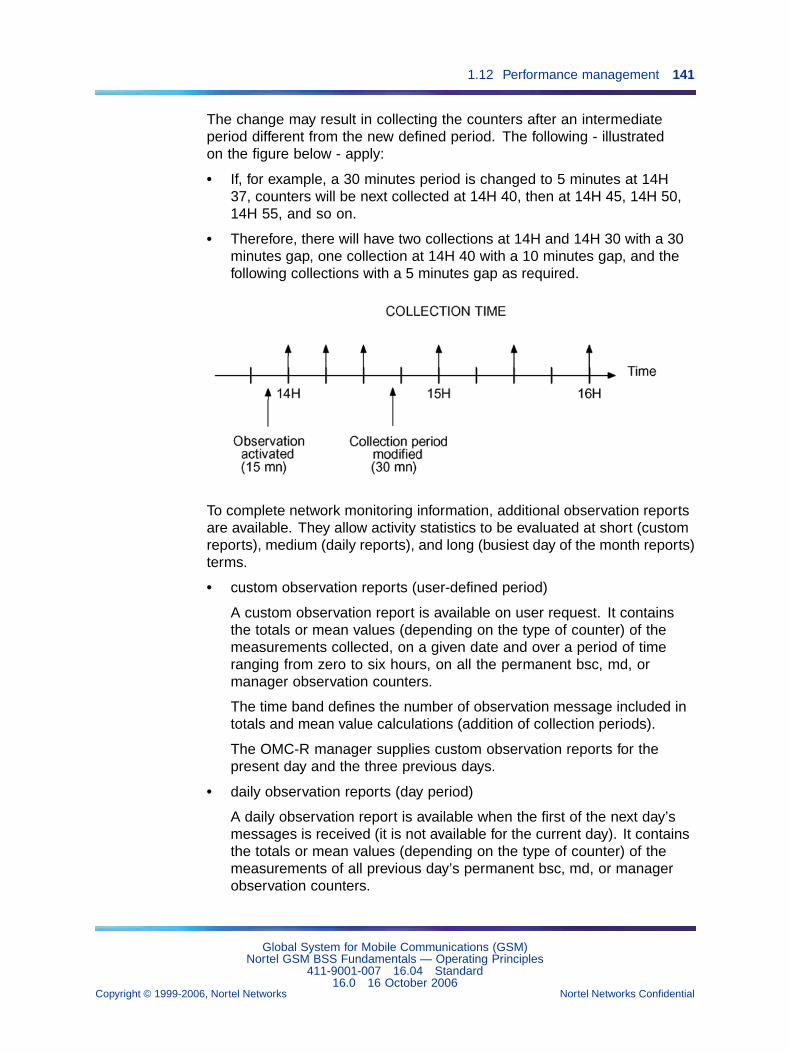
1.12 Performance management 141
The change may result in collecting the counters after an intermediateperiod different from the new defined period. The following - illustratedon the figure below - apply:
• If, for example, a 30 minutes period is changed to 5 minutes at 14H37, counters will be next collected at 14H 40, then at 14H 45, 14H 50,14H 55, and so on.
• Therefore, there will have two collections at 14H and 14H 30 with a 30minutes gap, one collection at 14H 40 with a 10 minutes gap, and thefollowing collections with a 5 minutes gap as required.
To complete network monitoring information, additional observation reportsare available. They allow activity statistics to be evaluated at short (customreports), medium (daily reports), and long (busiest day of the month reports)terms.
• custom observation reports (user-defined period)
A custom observation report is available on user request. It containsthe totals or mean values (depending on the type of counter) of themeasurements collected, on a given date and over a period of timeranging from zero to six hours, on all the permanent bsc, md, ormanager observation counters.
The time band defines the number of observation message included intotals and mean value calculations (addition of collection periods).
The OMC-R manager supplies custom observation reports for thepresent day and the three previous days.
• daily observation reports (day period)
A daily observation report is available when the first of the next day’smessages is received (it is not available for the current day). It containsthe totals or mean values (depending on the type of counter) of themeasurements of all previous day’s permanent bsc, md, or managerobservation counters.
Global System for Mobile Communications (GSM)Nortel GSM BSS Fundamentals — Operating Principles
411-9001-007 16.04 Standard16.0 16 October 2006
Copyright © 1999-2006, Nortel Networks Nortel Networks Confidential
.
142 Chapter 1 General operating mechanisms
The totals and mean value calculations start at 0h on D-day and areupdated in real time as each new observation message is received thesame day.
The OMC-R manager can at most supply daily observation reports forthe last three days. The availability of the daily observation reportsdepends on purge configuration at manager level.
• busiest day of the month observation reports
An observation report on the busiest day of the month is the dailyobservation report generated on the day of the month during which thetotal values measured on a reference counter over a given referenceperiod were the highest. The reference period can be in the range of00 to 24 hours (it may be as follows: 08:00 - 19:00). The referencetime and counter are statically configured (raw BSS counter, or activeOMC-R agent or manager UNIX server counter).
The OMC-R manager supplies the busiest day of the month observationreport for the current and previous months. The busiest day of thecurrent month observation report is available as soon as the second dayof the month is started and is updated each day until the first day ofthe following month.
1.12.2.4 Custom report and daily report counter processingAn elementary report is the report that uses data collected when the definedmdGranularityPeriod elapses.
A custom or daily report is established from a number (N) of elementaryreports calculated by adding the periods of each elementary report itcontains. For example, a custom report covering a period of two hours cancontain three elementary reports of 30 minutes each and two elementaryreports of 15 minutes each.
The method used to calculate a custom or daily report depends on the typeof counter involved (cumulative, value, or load).
Elementary report counters Let i be the elementary report number:
• cumulative counter Ti:
— Tcvi = total of Ti
• value counter Vi:
— Vcvi = total of Vi
— Vnei = number of samples in Vi
— Vavi = average of Vi = Vcvi / Vnei
Global System for Mobile Communications (GSM)Nortel GSM BSS Fundamentals — Operating Principles
411-9001-007 16.04 Standard16.0 16 October 2006
Copyright © 1999-2006, Nortel Networks Nortel Networks Confidential
.
1.12 Performance management 143
• load counter Ci:
— Ccvi = total of Ci
— Cnei = number of samples in Ci
— Cavi = average of Ci = Ccvi / Cnei
Custom or daily report counters Let n be the number of elementaryreports in the custom or daily report:
• total cumulative counter value:
— Tcv = Tcv1 + Tcv2 + ... + Tcvn
• mean value counter value:
— Vav = (Vcv1 + Vcv2 + ... + Vcvn) / (Vne1 + Vne2 + ... + Vnen)
• mean load counter value:
— Cav = (Cav1 + Cav2 + ... + Cavn) / n
1.12.2.5 Storing permanent observation recordsStorage and transfer Two modes of sending observation results to theOMC-R are used depending on the observation type. These are describedbelow :
• The first mode is direct access to the OMC-R for the messages related tothe temporary (only for the BSC 12000HC) and the real time observation.
— Temporary observations are stored at the end of each period ofobservation in a circular file able to contain 24 hours of observationat most.
— Real time observations are stored at the end of each period ofobservation in a circular file able to contain only one message.
• The second mode uses the standard protocol of File Transfer (FTAM).This mode is necessary for counter messages related to general statisticobservation, fast statistic observation and diagnostic observation. Onefile per observation type, named with its collecting date, is opened foreach counter message. This file is also mirrored. After concatenationof the segments and the storage of the complete message on the disk,an event report is sent to the OMC-R file, signalling the existing file.The OMC-R has to read and then to delete this file according to theFTAM protocol.
BSC 12000HC observation record store Each time the definedmdGranularityPeriod expires, the observation counters are collected and anobservation record is generated. It is stored in a file of the :GPO: partition
Global System for Mobile Communications (GSM)Nortel GSM BSS Fundamentals — Operating Principles
411-9001-007 16.04 Standard16.0 16 October 2006
Copyright © 1999-2006, Nortel Networks Nortel Networks Confidential
.
144 Chapter 1 General operating mechanisms
on BSC 12000HC disks with relevant information, such as serial number,measurement time, an collection period. The BSC 12000HC informs theOMC-R agent that a new observation file is ready for transfer.
In normal operating conditions, the observation file is immediatelytransferred and automatically purged from the :GPO: partition.
For some reason, particularly in case of BSS/OMC-R link outage or when aBSC 12000HC audit is in progress, it may not be possible to transfer the file.Then it is stored in the :GPO: partition with all subsequent observation filesuntil the link is restored or the audit ends (see the following figure).
If the :GPO: partition of the BSC 12000HC is saturated, then BSC 12000HCremoves the whole partition.
When the BSS/OMC-R link is restored or the audit ends, the files aretransferred in chronological order and purged from the :GPO: partition.
If the BSC 12000HC switches over to the standby chain, the file transfer(when the BSS/OMC-R link is operational) or storage (when the link isdown) continues since the BSC 12000HC processing chains are mirrored.
If the BSC 12000HC application database is rebuilt, some records maybe lost since the BSC automatically deletes any record collected but nottransferred once its database is rebuilt.
The :GPO: partition can store all the observation files generated in a24-hour period. In case of overflow, then the BSC 12000HC deletes allthe files that are over 24 hours old.
All the observation records received more than three days after they werecollected are purged the following night. The OMC-R automatic purgefunction only recognizes the date included in the OMC-R file name.
BSC 3000 observation record store General statistic observation, faststatistic observation and diagnostic observations are stored at the end ofeach period of observation in the corresponding file on a disk partition ofthe BSC 3000. The name of the partition in Unix is "/OMU/share /log/".This partition is sized in order to be able to contain at least 72 hours ofobservation. After 72 hours, the messages will be discarded each hour,
• a warning will be sent to the OMC-R as well as the name of associatedfile.
• if no place is available, a hardware anomaly, as well as the name of thepartition, will be sent to the OMC-R.
Global System for Mobile Communications (GSM)Nortel GSM BSS Fundamentals — Operating Principles
411-9001-007 16.04 Standard16.0 16 October 2006
Copyright © 1999-2006, Nortel Networks Nortel Networks Confidential
.
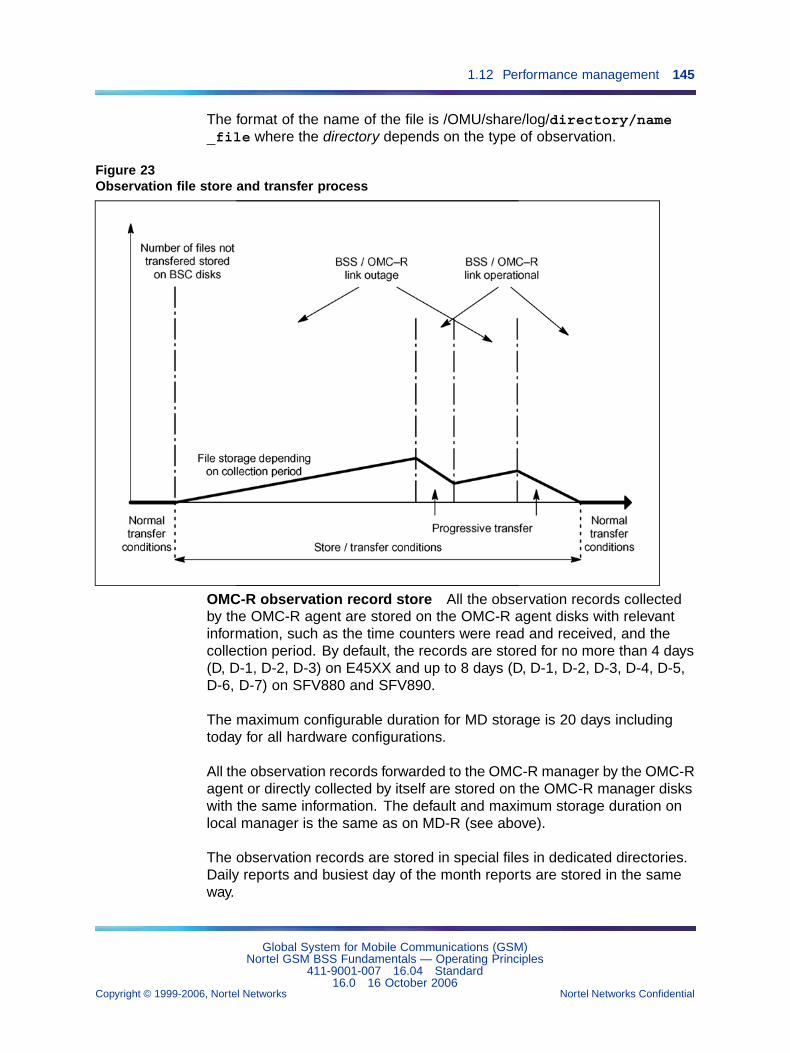
1.12 Performance management 145
The format of the name of the file is /OMU/share/log/directory/name_file where the directory depends on the type of observation.
Figure 23Observation file store and transfer process
OMC-R observation record store All the observation records collectedby the OMC-R agent are stored on the OMC-R agent disks with relevantinformation, such as the time counters were read and received, and thecollection period. By default, the records are stored for no more than 4 days(D, D-1, D-2, D-3) on E45XX and up to 8 days (D, D-1, D-2, D-3, D-4, D-5,D-6, D-7) on SFV880 and SFV890.
The maximum configurable duration for MD storage is 20 days includingtoday for all hardware configurations.
All the observation records forwarded to the OMC-R manager by the OMC-Ragent or directly collected by itself are stored on the OMC-R manager diskswith the same information. The default and maximum storage duration onlocal manager is the same as on MD-R (see above).
The observation records are stored in special files in dedicated directories.Daily reports and busiest day of the month reports are stored in the sameway.
Global System for Mobile Communications (GSM)Nortel GSM BSS Fundamentals — Operating Principles
411-9001-007 16.04 Standard16.0 16 October 2006
Copyright © 1999-2006, Nortel Networks Nortel Networks Confidential
.
146 Chapter 1 General operating mechanisms
The directories and observation file naming rules are described in Section1.12.6 "OMC-R message store" (page 163).
1.12.2.6 Consulting permanent observation reportsUsers can only display and print permanent observation reports duringwork sessions. Reports are not automatically displayed and printed butmust be requested.
The reports are available immediately after the defined collection timeexpires.
A manufacturer’s file stored in the "/OMC/config/locale/en" directory on theOMC-R manager disks describes the display presentation format.
Other than the actual observation data, the reports contain the followinginformation:
• report level (adjacentCellHandOver, bts, bsc, md, manager,transceiverZone, tdma)
• identifier of the observed object (for all BSS reports), OMC-R agent (mdreport), OMC-R manager and connected workstations (manager report)
• date and time of counter collection by the BSC (permanent bscobservation reports), the OMC-R agent (permanent md observationreport), or the OMC-R manager (permanent manager observationreport)
• date and time the OMC-R agent received the messages (permanent bscand md observations) or the OMC-R manager collected the messages(permanent manager observation)
• effective observation run time
Users may also consult the current and the last three days’ custom reports,the last three daily reports, and the busiest day of the month reports forthe current and previous months.
• On the BSC 3000, the collection of the information is duplex (mirror diskand duplex OMU), but the entities where we collect the observationsmay be themselves duplex (swact of activity of any entity of the BSC).Typically, it is possible that collection of observations on specific objet istemporarily unavailable, lost or not representative because of a swact ofactivity inside the system.
1.12.2.7 Archiving permanent observation messagesThe permanent observation messages stored before the current day canbe backed up and restored on--line.
Global System for Mobile Communications (GSM)Nortel GSM BSS Fundamentals — Operating Principles
411-9001-007 16.04 Standard16.0 16 October 2006
Copyright © 1999-2006, Nortel Networks Nortel Networks Confidential
.
1.12 Performance management 147
The right to archive permanent observation messages is set in configurationdata the user can modify when the mdScanner object describing theobservation is created.
Observation message archiving parameters are statically configured (seeNTP < 006 >). All the reports generated on a given date are archived (rawreports, daily reports, busiest day of the month reports).
1.12.2.8 Permanent observation synthetic countersThere are two types of permanent observation synthetic counters:"manufacturer" and "operator".
The "manufacturer" synthetic counters are defined by Nortel and cannot bemodified by the user. They are delivered with the OMC-R. They are storedin files whose names are: *_nmc_formulas.dat (where * is bss, omc, or pcu).
The "operator" synthetic counters are defined by the user and can bemodified using the Synthetic Counters Editor tool (and reloaded on userrequest). They are stored in files whose names are: *_operator_formulas.cfg(where * is bss, omc, or pcu).
The following operations are allowed:
• add, subtract, multiply, divide
• total of all counter occurrences
• minimum of all counter occurrences
• maximum of all counter occurrences
• mean value of all counter occurrences
BSS permanent observation The manufacturer file is in the directory"/OMC/data/perf" directory (on the OMC-R manager disks) and its nameis "bss_nmc_formulas.dat".
The operator file is in the directory "/OMC/data/custo_config/config"directory and its name is "bss_operator_formulas.cfg".
Synthetic counters are uniquely identified in the OMC-R. They are displayedusing the appropriate formatting file with observation reports.
When consulting a permanent bsc observation report, the user can choosewhether to include synthetic counters in the report.
OMC-R agent and manager permanent observations The manufacturerfile is in the directory "/OMC/data/perf" directory (on the OMC-R managerdisks) and its name is "omc_nmc_formulas.dat".
Global System for Mobile Communications (GSM)Nortel GSM BSS Fundamentals — Operating Principles
411-9001-007 16.04 Standard16.0 16 October 2006
Copyright © 1999-2006, Nortel Networks Nortel Networks Confidential
.
148 Chapter 1 General operating mechanisms
The operator file is in the directory "/OMC/data/custo_config/c onfig"directory and its name is "omc_operator_formulas.cfg".
Permanent md and manager observation synthetic counters are uniquelyidentified in the OMC-R and are part of these permanent observations.
PCUSN permanent observation It is possible to have synthetic countersfor the PCUSN.
The manufacturer file is in the directory "/OMC/data/perf" directory (on theOMC-R manager disks) and its name is "pcu_nmc_formulas.dat".
The operator file is in the directory "/OMC/data/custo_config/config"directory and its name is "pcu_operator_formulas.cfg".
1.12.2.9 Counter threshold crossingBSS permanent observation (GSM and GPRS services)
Raw counters (BSS only) When the OMC-R agent PerformanceManagement function receives a BSS permanent observation message, itanalyzes the counters contained in the message.
If for the first time one of the counters crosses the limits defined by theoperator (values above or below the high and low thresholds defined withthe associated mdWarning object), the OMC-R agent sends a message tothe Fault Management function that may issue a notification or generate analarm. Refer to Section 1.13 " Fault management" (page 177).
The mdWarning functionality is available only for OFS observations (not forall BSS permanent observations).
Figure 24 "Threshold crossing detection" (page 149) shows the thresholdcrossing message generation mechanisms.
For a cumulative counter, the accounting time used for the test is set to oneminute in static configuration data. The threshold values correspond tothe defined accounting time and are independent of the counter collectionperiod.
Four types of messages are generated:
• M1 on start of high threshold crossing (S1H)
• M2 on end of high threshold crossing (S2H)
• M3 on start of low threshold crossing (S1B)
• M4 on end of low threshold crossing (S2B)
Global System for Mobile Communications (GSM)Nortel GSM BSS Fundamentals — Operating Principles
411-9001-007 16.04 Standard16.0 16 October 2006
Copyright © 1999-2006, Nortel Networks Nortel Networks Confidential
.
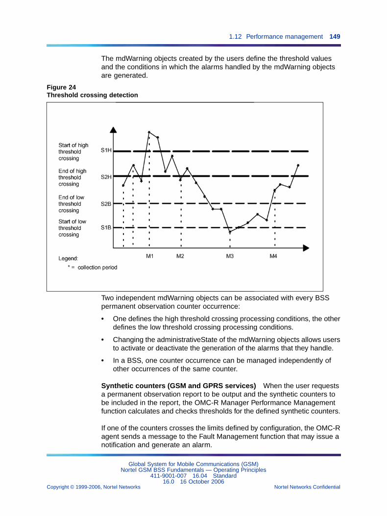
1.12 Performance management 149
The mdWarning objects created by the users define the threshold valuesand the conditions in which the alarms handled by the mdWarning objectsare generated.
Figure 24Threshold crossing detection
Two independent mdWarning objects can be associated with every BSSpermanent observation counter occurrence:
• One defines the high threshold crossing processing conditions, the otherdefines the low threshold crossing processing conditions.
• Changing the administrativeState of the mdWarning objects allows usersto activate or deactivate the generation of the alarms that they handle.
• In a BSS, one counter occurrence can be managed independently ofother occurrences of the same counter.
Synthetic counters (GSM and GPRS services) When the user requestsa permanent observation report to be output and the synthetic counters tobe included in the report, the OMC-R Manager Performance Managementfunction calculates and checks thresholds for the defined synthetic counters.
If one of the counters crosses the limits defined by configuration, the OMC-Ragent sends a message to the Fault Management function that may issue anotification and generate an alarm.
Global System for Mobile Communications (GSM)Nortel GSM BSS Fundamentals — Operating Principles
411-9001-007 16.04 Standard16.0 16 October 2006
Copyright © 1999-2006, Nortel Networks Nortel Networks Confidential
.
150 Chapter 1 General operating mechanisms
Threshold values and alarm processing conditions are defined in theconfiguration file.
One should note that, unlike raw counters, the following apply:
The high and low thresholds associated to the definition of a syntheticcounter are used for all the occurrences of this counter. For instance ifthe "TOTO" counter of bts class has two thresholds H and L, these twothresholds apply to the "TOTO" counter in all the bts objects (bts1, bts2, ...).
1.12.3 Performance Monitor observation1.12.3.1 Performance Monitor observation managementThe performance monitor (ORT, and OFS) observation must be startedwhen the BSS starts up for the first time by creating an mdScanner object.The observation can be stopped by deleting the mdScanner object but thisis not recommended.
The Display command on the object indicates whether the observationis running, and allows users to check the counter collection period(mdGranularityPeriod parameter) and other characteristics. The collectionperiod can be changed while the observation is running.
The Performance Monitor observation uses the raw counters collected bythe BSS and the synthetic counters processed by the OMC-R. When thePerformance Monitor window is opened, the report the user accesses is anhistorical report on the selected counters over the period configured in the"Display only last ... hours (<2)" field of the Performance Monitor window.
1.12.3.2 Performance Monitor observation periodsThe mdGranularityPeriod periods are used to manage this observation:
• The value of the period at which performance monitor data are collectedin a BSS may vary independently of the collection periods of other BSSscontrolled by the same OMC-R.
The authorized values for ORT are 1, 2, 3, 4, and 5 minutes, and forOFS (available in the Performance Monitor window from V12), 15,30, and 60 minutes.
1.12.3.3 Performance Monitor observation report availabilityThe following reports are available on user request:
• bsc
• btsSiteManager
• bts
• pcmCircuit
Global System for Mobile Communications (GSM)Nortel GSM BSS Fundamentals — Operating Principles
411-9001-007 16.04 Standard16.0 16 October 2006
Copyright © 1999-2006, Nortel Networks Nortel Networks Confidential
.
1.12 Performance management 151
• adjacentCellHandover
• transceiverZone
• tdma
• omu
• tmu
• cc
• cem
• pcmPort
• signallingLink
• channel
The report is refreshed when new observation messages are received.
1.12.3.4 Storing Performance Monitor observation messagesBSC observation message store Each time the definedmdGranularityPeriod expires, the observation counters are collected and anobservation message is generated. It is stored in a file of the :GPO: partitionon BSC 12000HC disks with relevant information, such as serial number,measurement time, and collection period. The BSC 12000HC informs theOMC-R agent when a new observation message is ready for transfer.
In normal operating conditions, the observation message is immediatelytransferred and automatically purged from the :GPO: partition.
For some reason, particularly in case of BSS/OMC-R link outage or when aBSC 12000HC audit is in progress, it may not be possible to transfer themessages. Then they are stored in the :GPO: partition with all subsequentobservation messages until the link is restored or the audit ends.
If the :GPO: partition of the BSC 12000HC is saturated, then BSC 12000HCremoves the whole partition.
When the BSS/OMC-R link is restored or the audit ends, the messages aretransferred in chronological order and purged from the :GPO: partition.
If the :GPO: partition of the BSC 12000HC is saturated, it is deleted.
If the BSC 12000HC switches over to the standby chain, the messagetransfer (when the BSS/OMC-R link is operational) or storage (when the linkis down) continues since the BSC 12000HC processing chains are mirrored.
Global System for Mobile Communications (GSM)Nortel GSM BSS Fundamentals — Operating Principles
411-9001-007 16.04 Standard16.0 16 October 2006
Copyright © 1999-2006, Nortel Networks Nortel Networks Confidential
.
152 Chapter 1 General operating mechanisms
If the BSC 12000HC application database is rebuilt, some messages maybe lost since the BSC automatically deletes any message collected but nottransferred once its database is rebuilt.
The :GPO: partition can store all the observation messages generated in a24-hour period. In case of overflow, then the BSC 12000HC deletes all themessages that are over 24 hours old.
All the observation messages received more than three days after theywere collected are purged the following night. The OMC-R automatic purgefunction only recognizes the date included in the OMC-R file name.
OMC-R observation message store See the section "OMC-Robservation record store" in Section 1.12.2.5 "Storing permanentobservation records" (page 143).
1.12.3.5 Updating Performance Monitor observation reportsThe OMC-R Manager only keeps in memory the last record received.
When a user requests a report in Performance Monitor, all the informationis immediately displayed. The data are automatically updated after eachcollection.
1.12.3.6 Consulting Performance Monitor observation reportsUsers can display and print performance monitor observation reports duringa work session or from an off-line terminal. Reports are not automaticallydisplayed and printed but must be requested.
"Performance monitor" windows are partnered with an output class (referto Section 1.16 "Security management" (page 231) in this chapter). Thereports that can be consulted are available immediately after the definedcollection time.
The configuration files defining the presentation of text ORT report arestored in /OMC/config/locale/en/<xxVyy>, where <xxVyy> can be 2GV12,2GV15, 3GV14, 3GV15 and 3GV16.
Other than the actual observation data, the reports contain the followinginformation:
• report level (bts, bsc)
• observed cell (bts report) or BSC (bsc report) reference number
• date and time of counter collection by the BSC
• date and time of message reception by the OMC-R agent
• effective observation period
Global System for Mobile Communications (GSM)Nortel GSM BSS Fundamentals — Operating Principles
411-9001-007 16.04 Standard16.0 16 October 2006
Copyright © 1999-2006, Nortel Networks Nortel Networks Confidential
.
1.12 Performance management 153
1.12.3.7 Archiving Performance Monitor observation messagesPerformance Monitor observation messages are only intended for real timedisplays. They are not stored, on the OMC-R disks and cannot be archived.
1.12.3.8 Performance Monitor observation synthetic countersThere are two types of Performance Monitor observation synthetic counters:"manufacturer" and "operator".
The "manufacturer" synthetic counters are defined by Nortel and cannot bemodified by the user. They are delivered with the OMC-R. They are storedin the "/OMC/data/perf/bss_nmc_formulas.dat" file.
The "operator" synthetic counters are defined by the userand can be modified using the Synthetic Counters Editortool (and reloaded on user request). They are stored in the"/OMC/data/custo_config/config/bss_operator_formulas.cfg" file.
The following operations are allowed:
• add, subtract, multiply, divide
• total of all counter occurrences
• minimum of all counter occurrences
• maximum of all counter occurrences
• mean value of all counter occurrences
Performance Monitor observation synthetic counters are uniquely identifiedin the OMC-R and are part of the BSS Performance Monitor observation.They are displayed using the appropriate formatting file with BSSPerformance Monitor observation reports.
When consulting a Performance Monitor observation report, the user canchoose whether to include synthetic counters in the report.
1.12.4 Temporary observation for BSC 12000HC only1.12.4.1 Temporary observation managementBSS permanent and Performance Monitor observations should not beinterrupted and are an essential part of network performance monitoring.
Users can start temporary observation measurements (by creating anmdScanner object) to obtain additional information on the performance ofa particular BSS entity in case of operating problems. To stop temporaryobservation measurements, the user deletes the mdScanner object whenthe problem is solved or when sufficient information has been supplied.
Global System for Mobile Communications (GSM)Nortel GSM BSS Fundamentals — Operating Principles
411-9001-007 16.04 Standard16.0 16 October 2006
Copyright © 1999-2006, Nortel Networks Nortel Networks Confidential
.
154 Chapter 1 General operating mechanisms
The Display command on the mdScanner object indicates whether theobservation is running and allows the user to check the counter collectionperiod (mdGranularityPeriod parameter), and the observation run time(stopTime parameter). The observation collection period and durationcannot be modified while the observation is running.
A temporary observation is stopped by the OMC-R agent when thestopTime timer expires or when the user deletes the mdScanner object. Ifthe observation is still running when the user closes the work session, theobservation continues until the defined run time expires.
Notes:
• The user must specify a stopTime for a temporary observation byapplying the following rule:
startTime + mdGranularityPeriod < stopTime <startTime + 24 h
Thus, at least one observation record is collected.
• Concerning the last record, since the collections take place at instantsmultiple of mdGranularityPeriod (ex: H:00, H:30, for mdGranularityPeriod = 30 min), if the observation expiration occurs at H:03, the lastcollected record will be the one of H:00.
Restrictions regarding temporary observation management are thefollowing:
• Two temporary observations of the same type cannot be run at thesame time in a BSS.
• Temporary observations in a BSS cannot be stopped before thestopTime timer expires if the BSS/OMC-R link is down or if a BSCdatabase audit is in--progress.
• The number of temporary observations that can be run simultaneouslyon all the BSSs controlled by the OMC-R agent is limited.
BSS temporary observation measurements only produce raw counters.
1.12.4.2 Temporary observation periods and run timesThe mdGranularityPeriod periods and stopTime run times are used tomanage this observation:
• The value of the period at which temporary observation data arecollected in a BSS may vary independently of the temporary observationcollection periods of other BSSs controlled by the OMC-R agent.
The authorized values, for all temporary observation types (except forODIAG) are 5, 10, 15, 30 and 60 minutes.
For ODIAG the only authorized value is 15 minutes.
Global System for Mobile Communications (GSM)Nortel GSM BSS Fundamentals — Operating Principles
411-9001-007 16.04 Standard16.0 16 October 2006
Copyright © 1999-2006, Nortel Networks Nortel Networks Confidential
.
1.12 Performance management 155
• A temporary observation run time must be greater or equal to thedefined collection period and is limited to 1440 minutes (24 hours).
1.12.4.3 Temporary observation report generationThe following types of BSS observations can be run:
• Interference temporary observation
• Abis Interface temporary observation
• SS7 link temporary observation
• ODIAG
Additional custom observation reports are available to evaluate activitystatistics at short terms:
• A custom report per temporary observation is available on user request.It contains the totals or mean values (depending on the type of counter)of the measurements collected on a given date and over a period oftime ranging from zero to six hours, on all the temporary observationcounters.
• The time band defines the number of observation message included intotals and mean value calculations (addition of collection periods).
• The OMC-R manager supplies custom observation reports for thepresent day and the three previous days.
1.12.4.4 Storing temporary observation messagesBSC observation message store Each time the definedmdGranularityPeriod expires, the observation counters are collected andtemporary observation records are generated. They are stored in a circularfile created in the :TO: partition on the BSC disks with relevant information,such as serial number, time of reading, and collection period. The BSCinforms the OMC-R agent when a new observation record is ready fortransfer.
In normal working conditions, the observation records are immediatelytransferred to the OMC-R agent and the circular file is progressively purged.
For some reason, particularly in case of BSS/OMC-R link outage or if aBSC audit is in progress, it may not be possible to transfer the observationrecords to the OMC-R agent. The data are stored in the circular file untilthe link is restored or the audit ends.
As soon as the link is restored or the audit ends, the records are sent to theOMC-R agent one by one, starting with the oldest record. The frequency oftransfer is set at 20 seconds in static configuration data.
Global System for Mobile Communications (GSM)Nortel GSM BSS Fundamentals — Operating Principles
411-9001-007 16.04 Standard16.0 16 October 2006
Copyright © 1999-2006, Nortel Networks Nortel Networks Confidential
.
156 Chapter 1 General operating mechanisms
The same process shown on Figure 23 "Observation file store andtransfer process" (page 145) is used for storing and transferring temporaryobservation records.
The circular file can store all the records generated in a 24-hours period.
If the BSC switches over to the standby chain, the message transfer (whenthe BSS/OMC-R link is operational) or storage (when the link is down)continues since the BSC processing chains are mirrored.
If the BSC application database is rebuilt, some records may be lost sincethe BSC automatically deletes any record collected but not transferred onceits database is rebuilt.
All observation records received more than three days after they werecollected are purged the following night. The OMC-R automatic purgefunction only recognizes the date included in the OMC-R file name.
1.12.4.5 Statutory time changeWhen the statutory time changes (from Summer to Winter time, andvice--ver sa), temporary observation run times are decreased or increasedaccordingly.
1.12.4.6 Consulting temporary observation reportsUsers can only display and print temporary observation reports duringwork sessions. Reports are not automatically displayed and printed butmust be requested.
A user can request a report while the observation is running or after itstopped. The reports are available after each defined collection time.
A manufacturer’s file stored in /OMC/config/locale/en/<xxVyy> (where<xxVyy> can be 2GV12, 2GV15, 3GV14, 3GV15 and 3GV16) on theOMC-R manager disks describes the display presentation format.
Other than the actual observation data, the reports contain the followinginformation:
• report type: handOver, interference, etc.
• reference numbers of the observed objects on the OMC-R
• date and time of counter collection by the BSC
• date and time of message reception by the OMC-R agent
• effective observation period
1.12.4.7 Archiving temporary observation messagesThe temporary observation messages stored before the current day canbe backed up and restored on-line.
Global System for Mobile Communications (GSM)Nortel GSM BSS Fundamentals — Operating Principles
411-9001-007 16.04 Standard16.0 16 October 2006
Copyright © 1999-2006, Nortel Networks Nortel Networks Confidential
.
1.12 Performance management 157
The right to archive temporary observation reports is defined in configurationdata the user can update when the mdScanner object describing thetemporary observation is created.
Observation message archiving is defined in static configuration data (seeNTP < 006 >) for a given date. It concerns all the raw reports generated onthe given date.
1.12.5 Trace management1.12.5.1 PrinciplesCall tracing function The Call tracing function is unique in a BSS andallows, on MSC request, to record information related to one or more callscontrolled by the BSC.
Trace data storage is activated at BSC level on receipt of the BSSMAP MSCTRACE INVOKE message (MSC Phase II) or the BSSMAP TRACE INVOKEmessage (MSC Phase I) issued by the MSC. Trace characteristics (type oftransfer according to the trace priority, type of trace = basic, handover, radio)are transmitted to the BSC through this message.
Tracing a call ends when the call is no more controlled by the BSC, that iswhen the call ends or when an outgoing handover is performed.
The BSS Call tracing function is activated by creating a traceControl object.It is deactivated when the object is locked or deleted.
The Display command on that objet allows the user to know if the functionis active (unlocked object) and check its characteristics. They can bemodified when the traceControl object is locked.
Call path tracing function The Call path tracing function (follow-up ofcalls using common resources) is unique in a BSS and is controlled by theBSC. It allows to record information related to calls using selected resourcesin the BSS, such as set of cells, set of TRX/DRXs, set of terrestrial circuits.
During a path tracing follow-up, all calls that enter the observation area areautomatically traced by the BSC (in the limits set for each type of trace). Forexample, if only one terrestrial circuit is observed and a call is establishedon that circuit when the Call path tracing function is activated, then thecall is automatically traced.
Tracing a call ends when the call stops using the traced resources or whenthe path tracing follow-up stops.
The BSS Call path tracing function is activated by creating a callPathTraceobject. It is deactivated when the object is locked or deleted.
Global System for Mobile Communications (GSM)Nortel GSM BSS Fundamentals — Operating Principles
411-9001-007 16.04 Standard16.0 16 October 2006
Copyright © 1999-2006, Nortel Networks Nortel Networks Confidential
.
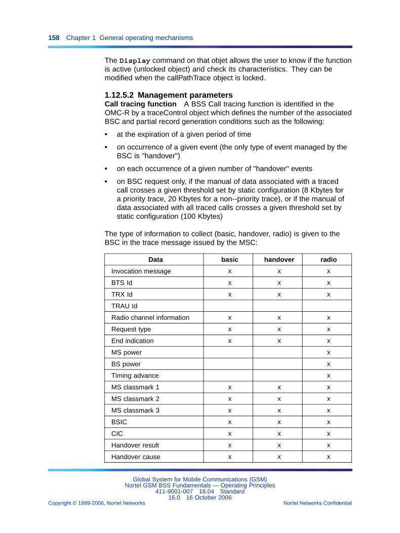
158 Chapter 1 General operating mechanisms
The Display command on that objet allows the user to know if the functionis active (unlocked object) and check its characteristics. They can bemodified when the callPathTrace object is locked.
1.12.5.2 Management parametersCall tracing function A BSS Call tracing function is identified in theOMC-R by a traceControl object which defines the number of the associatedBSC and partial record generation conditions such as the following:
• at the expiration of a given period of time
• on occurrence of a given event (the only type of event managed by theBSC is "handover")
• on each occurrence of a given number of "handover" events
• on BSC request only, if the manual of data associated with a tracedcall crosses a given threshold set by static configuration (8 Kbytes fora priority trace, 20 Kbytes for a non--priority trace), or if the manual ofdata associated with all traced calls crosses a given threshold set bystatic configuration (100 Kbytes)
The type of information to collect (basic, handover, radio) is given to theBSC in the trace message issued by the MSC:
Data basic handover radio
Invocation message x x x
BTS Id x x x
TRX Id x x x
TRAU Id
Radio channel information x x x
Request type x x x
End indication x x x
MS power x
BS power x
Timing advance x
MS classmark 1 x x x
MS classmark 2 x x x
MS classmark 3 x x x
BSIC x x x
CIC x x x
Handover result x x x
Handover cause x x x
Global System for Mobile Communications (GSM)Nortel GSM BSS Fundamentals — Operating Principles
411-9001-007 16.04 Standard16.0 16 October 2006
Copyright © 1999-2006, Nortel Networks Nortel Networks Confidential
.
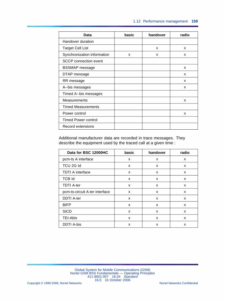
1.12 Performance management 159
Data basic handover radio
Handover duration
Target Cell List x x
Synchronization information x x x
SCCP connection event
BSSMAP message x
DTAP message x
RR message x
A--bis messages x
Timed A--bis messages
Measurements x
Timed Measurements
Power control x
Timed Power control
Record extensions
Additional manufacturer data are recorded in trace messages. Theydescribe the equipment used by the traced call at a given time :
Data for BSC 12000HC basic handover radio
pcm-ts A interface x x x
TCU 2G Id x x x
TDTI A interface x x x
TCB Id x x x
TDTI A-ter x x x
pcm-ts-circuit A-ter interface x x x
DDTI A-ter x x x
BIFP x x x
SICD x x x
TEI-Abis x x x
DDTI A-bis x x x
Global System for Mobile Communications (GSM)Nortel GSM BSS Fundamentals — Operating Principles
411-9001-007 16.04 Standard16.0 16 October 2006
Copyright © 1999-2006, Nortel Networks Nortel Networks Confidential
.
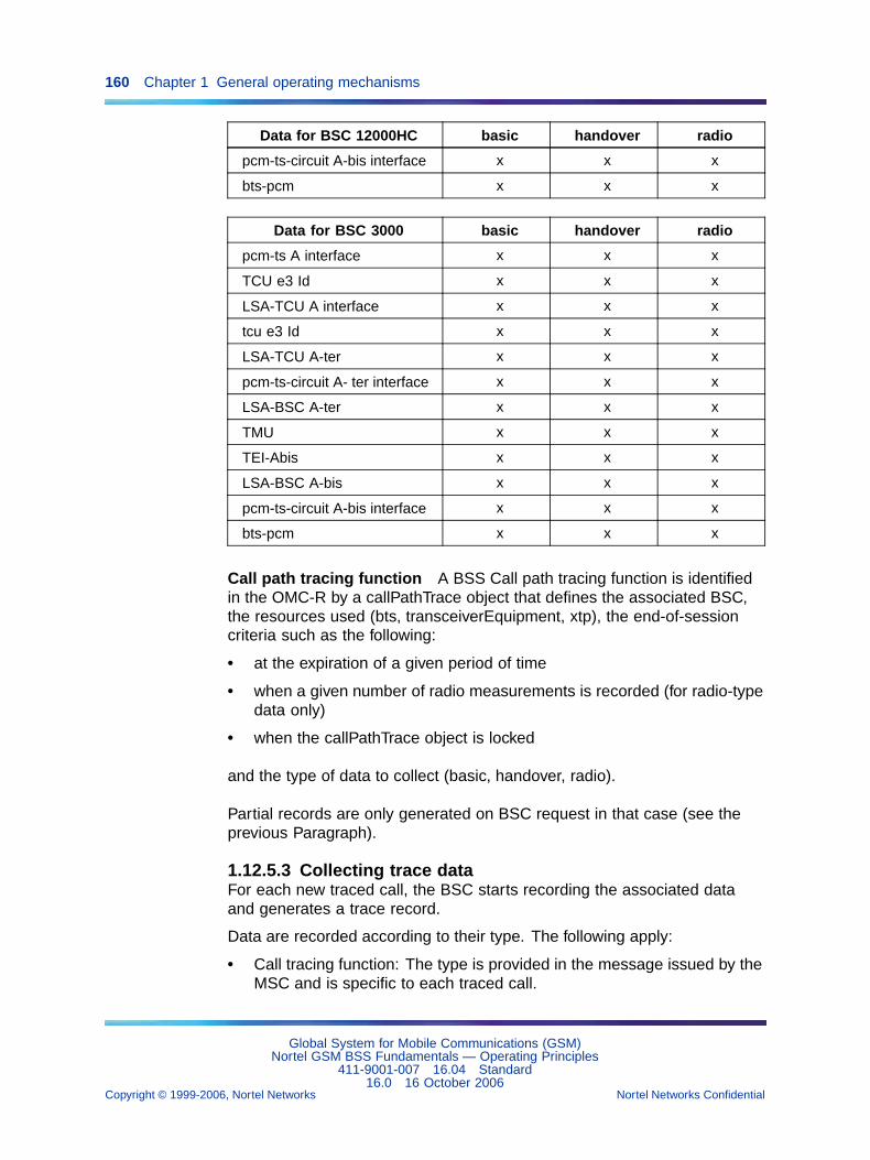
160 Chapter 1 General operating mechanisms
Data for BSC 12000HC basic handover radio
pcm-ts-circuit A-bis interface x x x
bts-pcm x x x
Data for BSC 3000 basic handover radio
pcm-ts A interface x x x
TCU e3 Id x x x
LSA-TCU A interface x x x
tcu e3 Id x x x
LSA-TCU A-ter x x x
pcm-ts-circuit A- ter interface x x x
LSA-BSC A-ter x x x
TMU x x x
TEI-Abis x x x
LSA-BSC A-bis x x x
pcm-ts-circuit A-bis interface x x x
bts-pcm x x x
Call path tracing function A BSS Call path tracing function is identifiedin the OMC-R by a callPathTrace object that defines the associated BSC,the resources used (bts, transceiverEquipment, xtp), the end-of-sessioncriteria such as the following:
• at the expiration of a given period of time
• when a given number of radio measurements is recorded (for radio-typedata only)
• when the callPathTrace object is locked
and the type of data to collect (basic, handover, radio).
Partial records are only generated on BSC request in that case (see theprevious Paragraph).
1.12.5.3 Collecting trace dataFor each new traced call, the BSC starts recording the associated dataand generates a trace record.
Data are recorded according to their type. The following apply:
• Call tracing function: The type is provided in the message issued by theMSC and is specific to each traced call.
Global System for Mobile Communications (GSM)Nortel GSM BSS Fundamentals — Operating Principles
411-9001-007 16.04 Standard16.0 16 October 2006
Copyright © 1999-2006, Nortel Networks Nortel Networks Confidential
.
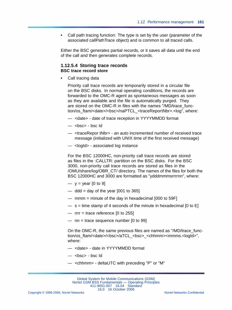
1.12 Performance management 161
• Call path tracing function: The type is set by the user (parameter of theassociated callPathTrace object) and is common to all traced calls.
Either the BSC generates partial records, or it saves all data until the endof the call and then generates complete records.
1.12.5.4 Storing trace recordsBSC trace record store
• Call tracing data
Priority call trace records are temporarily stored in a circular fileon the BSC disks. In normal operating conditions, the records areforwarded to the OMC-R agent as spontaneous messages as soonas they are available and the file is automatically purged. Theyare stored on the OMC-R in files with the names "/MD/trace_func-tion/os_ftam/<date>/<bsc>/naPTCL_<traceReportNbr>.<log", where:
— <date> - date of trace reception in YYYYMMDD format
— <bsc> - bsc Id
— <traceRepor tNbr> - an auto incremented number of received tracemessage (initialized with UNIX time of the first received message)
— <logId> - associated log instance
For the BSC 12000HC, non-priority call trace records are storedas files in the :CALLTR: partition on the BSC disks. For the BSC3000, non-priority call trace records are stored as files in the/OMU/share/log/OBR_CT/ directory. The names of the files for both theBSC 12000HC and 3000 are formatted as "ydddmmmsrrrrnn", where:
— y = year [0 to 9]
— ddd = day of the year [001 to 365]
— mmm = minute of the day in hexadecimal [000 to 59F]
— s = time stamp of 4 seconds of the minute in hexadecimal [0 to E]
— rrrr = trace reference [0 to 255]
— nn = trace sequence number [0 to 99]
On the OMC-R, the same previous files are named as "/MD/trace_func-tion/os_ftam/<date>/<bsc>/aTCL_<bsc>_<chhmm><mmms.<logId>",where:
— <date> - date in YYYYMMDD format
— <bsc> - bsc Id
— <chhmm> - deltaUTC with preceding "P" or "M"
Global System for Mobile Communications (GSM)Nortel GSM BSS Fundamentals — Operating Principles
411-9001-007 16.04 Standard16.0 16 October 2006
Copyright © 1999-2006, Nortel Networks Nortel Networks Confidential
.
162 Chapter 1 General operating mechanisms
— <logId> - associated log instance
Once a record is stored, a spontaneous message is sent to the OMC-Ragent, indicating that a new data file is available. Data are transferredusing FTAM, and under the OMC-R agent control.
• Call path tracing data
Non-priority traces are the only type that is possible for the callPathTrace.Non-priority traces are always archived. On the BSC 12000HC,non-priority callPathTrace file names are stored in the :CALLPATH:partition on the BSC disks in a file whose capacity is set by the user(parameter of the associated callPathTrace object).
When the file is full, a spontaneous message is sent to the OMC-Ragent, indicating that a new data file is available. Data are transferredusing FTAM, and under the OMC-R agent control.
A new file is then open and this file stores the new records of theongoing traces.
On the BSC 3000, non--priority callPathTrace records are stored as filesin the OMU/share/log/OBR_CPT/ directory. The names of the files forboth the BSC 12000HC and 3000 are formatted as "ydddmmms", where:
— y - year [0 to 9]
— ddd - day of the year [001 to 365]
— mmm - minute of the day in hexadecimal [000 to 59F]
— s - time stamp of 4 seconds of the minute in hexadecimal [0 to E]
• Special cases
When the BSC operations switch over to the standby chain, ongoing calltracing is stopped (all data are lost, unless they have been recorded inpartial records). New calls are automatically traced when the standbychain becomes active.
When the BSC application database is rebuilt, some messages may belost since the BSC automatically purges all collected messages thathave not been transferred once the database is rebuilt.
OMC-R trace record store Each trace record collected by the OMC-Ragent is stored on disk. The records are stored for no more than four days(D, D-1, D-2, D-3) by default. This period can be statically modified.
The maximum configurable duration for MD storage is 10 days includingtoday for all hardware configurations.
Global System for Mobile Communications (GSM)Nortel GSM BSS Fundamentals — Operating Principles
411-9001-007 16.04 Standard16.0 16 October 2006
Copyright © 1999-2006, Nortel Networks Nortel Networks Confidential
.
1.12 Performance management 163
Directories and trace file naming rules are described in the Section 1.12.6"OMC-R message store" (page 163).
1.12.5.5 Archiving trace dataTrace data stored before the current day can be backed up and restoredon--line.
Trace data archiving is defined in static configuration data (see NTP < 006>) for a given date. It concerns all the records generated on the given date.
1.12.6 OMC-R message store1.12.6.1 OMC-R agent message storeSpecific objects model observation and trace message storing by theOMC-R agent:
• The observationFileReadyRecord objects define the recording format ofpermanent observation data in observation logs.
• The mdScanReportRecord objects define the recording format oftemporary observation data in observation logs.
• The traceFileReadyRecord objects define the recording format ofnon--priority trace messages in trace logs.
• The traceLogRecord objects define the recording format of priority tracemessages in trace logs.
Directories The raw messages contained in elementary permanent andtemporary observation reports are stored in dedicated OMC-R agent diskdirectories
/MD/obs/os_ftam/yyyymmdd/nnn
where "yyyymmdd" is the date on which the OMC-R agent collected themessages and "nnn" is the reference number of the observed entity (BSC orOMC-R agent). For example, if bsc = 5, nnn is read "005".
The raw messages contained in trace reports are stored in dedicatedOMC-R agent disk directories
/MD/trace_function/os_ftam/yyyymmdd/nnn
where "yyyymmdd" and "nnn" have the same meaning as above.
A new directory is created when the first observation or trace record of theday is delivered. It stores all records delivered on that same day.
Raw messages are stored on OMC-R manager disks. See Section1.12.6.2 "OMC-R manager message store" (page 165).
Global System for Mobile Communications (GSM)Nortel GSM BSS Fundamentals — Operating Principles
411-9001-007 16.04 Standard16.0 16 October 2006
Copyright © 1999-2006, Nortel Networks Nortel Networks Confidential
.
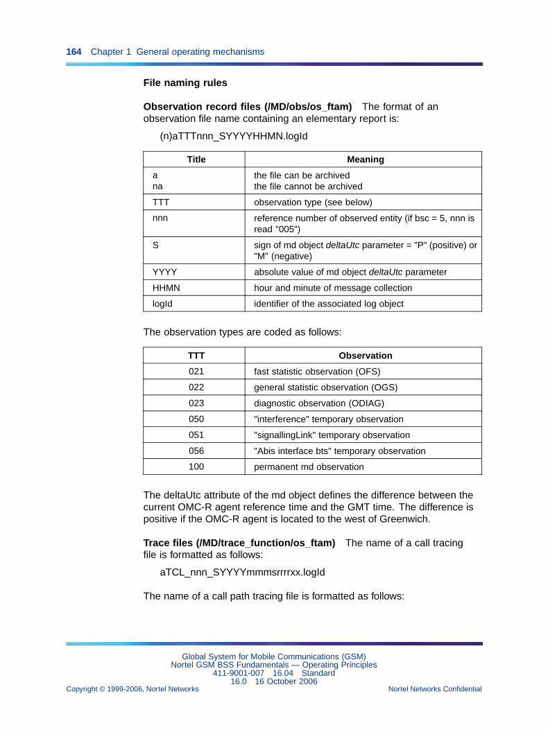
164 Chapter 1 General operating mechanisms
File naming rules
Observation record files (/MD/obs/os_ftam) The format of anobservation file name containing an elementary report is:
(n)aTTTnnn_SYYYYHHMN.logId
Title Meaning
ana
the file can be archivedthe file cannot be archived
TTT observation type (see below)
nnn reference number of observed entity (if bsc = 5, nnn isread "005")
S sign of md object deltaUtc parameter = "P" (positive) or"M" (negative)
YYYY absolute value of md object deltaUtc parameter
HHMN hour and minute of message collection
logId identifier of the associated log object
The observation types are coded as follows:
TTT Observation
021 fast statistic observation (OFS)
022 general statistic observation (OGS)
023 diagnostic observation (ODIAG)
050 "interference" temporary observation
051 "signallingLink" temporary observation
056 "Abis interface bts" temporary observation
100 permanent md observation
The deltaUtc attribute of the md object defines the difference between thecurrent OMC-R agent reference time and the GMT time. The difference ispositive if the OMC-R agent is located to the west of Greenwich.
Trace files (/MD/trace_function/os_ftam) The name of a call tracingfile is formatted as follows:
aTCL_nnn_SYYYYmmmsrrrrxx.logId
The name of a call path tracing file is formatted as follows:
Global System for Mobile Communications (GSM)Nortel GSM BSS Fundamentals — Operating Principles
411-9001-007 16.04 Standard16.0 16 October 2006
Copyright © 1999-2006, Nortel Networks Nortel Networks Confidential
.
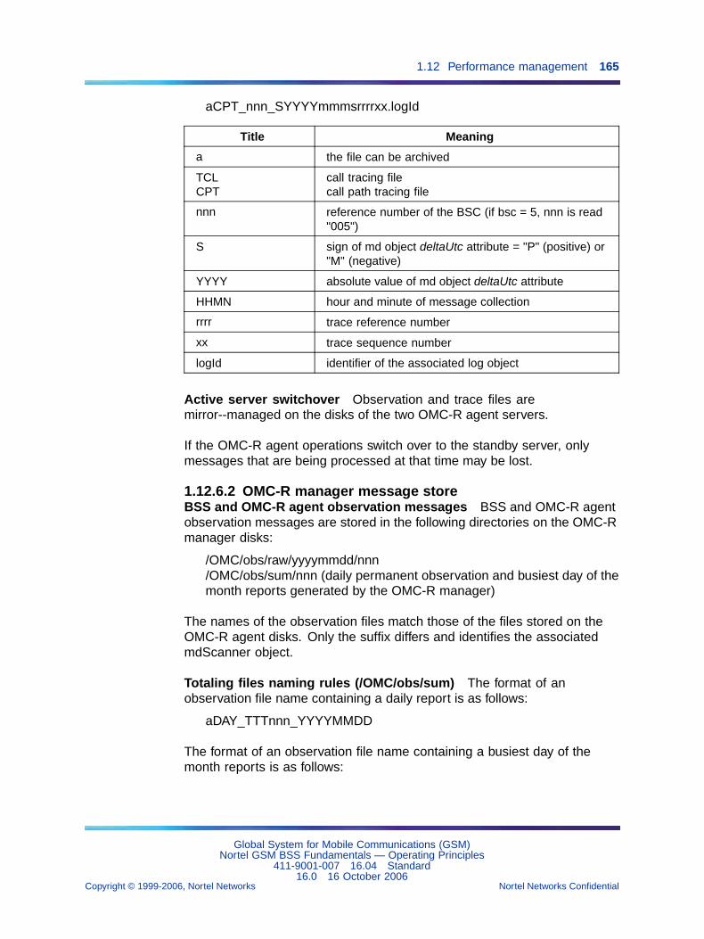
1.12 Performance management 165
aCPT_nnn_SYYYYmmmsrrrrxx.logId
Title Meaning
a the file can be archived
TCLCPT
call tracing filecall path tracing file
nnn reference number of the BSC (if bsc = 5, nnn is read"005")
S sign of md object deltaUtc attribute = "P" (positive) or"M" (negative)
YYYY absolute value of md object deltaUtc attribute
HHMN hour and minute of message collection
rrrr trace reference number
xx trace sequence number
logId identifier of the associated log object
Active server switchover Observation and trace files aremirror--managed on the disks of the two OMC-R agent servers.
If the OMC-R agent operations switch over to the standby server, onlymessages that are being processed at that time may be lost.
1.12.6.2 OMC-R manager message storeBSS and OMC-R agent observation messages BSS and OMC-R agentobservation messages are stored in the following directories on the OMC-Rmanager disks:
/OMC/obs/raw/yyyymmdd/nnn/OMC/obs/sum/nnn (daily permanent observation and busiest day of themonth reports generated by the OMC-R manager)
The names of the observation files match those of the files stored on theOMC-R agent disks. Only the suffix differs and identifies the associatedmdScanner object.
Totaling files naming rules (/OMC/obs/sum) The format of anobservation file name containing a daily report is as follows:
aDAY_TTTnnn_YYYYMMDD
The format of an observation file name containing a busiest day of themonth reports is as follows:
Global System for Mobile Communications (GSM)Nortel GSM BSS Fundamentals — Operating Principles
411-9001-007 16.04 Standard16.0 16 October 2006
Copyright © 1999-2006, Nortel Networks Nortel Networks Confidential
.
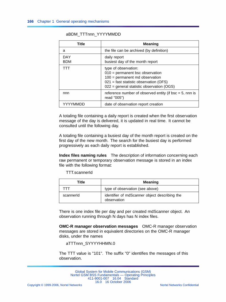
166 Chapter 1 General operating mechanisms
aBDM_TTTnnn_YYYYMMDD
Title Meaning
a the file can be archived (by definition)
DAYBDM
daily reportbusiest day of the month report
TTT type of observation:010 = permanent bsc observation100 = permanent md observation021 = fast statistic observation (OFS)022 = general statistic observation (OGS)
nnn reference number of observed entity (if bsc = 5, nnn isread "005")
YYYYMMDD date of observation report creation
A totaling file containing a daily report is created when the first observationmessage of the day is delivered, it is updated in real time. It cannot beconsulted until the following day.
A totaling file containing a busiest day of the month report is created on thefirst day of the new month. The search for the busiest day is performedprogressively as each daily report is established.
Index files naming rules The description of information concerning eachraw permanent or temporary observation message is stored in an indexfile with the following format:
TTT.scannerId
Title Meaning
TTT type of observation (see above)
scannerId identifier of mdScanner object describing theobservation
There is one index file per day and per created mdScanner object. Anobservation running through N days has N index files.
OMC-R manager observation messages OMC-R manager observationmessages are stored in equivalent directories on the OMC-R managerdisks, under the names
aTTTnnn_SYYYYHHMN.0
The TTT value is "101". The suffix "0" identifies the messages of thisobservation.
Global System for Mobile Communications (GSM)Nortel GSM BSS Fundamentals — Operating Principles
411-9001-007 16.04 Standard16.0 16 October 2006
Copyright © 1999-2006, Nortel Networks Nortel Networks Confidential
.
1.12 Performance management 167
Trace data Trace data are stored as tables in a dedicated database ofthe OMC-R manager.
1.12.7 Performance management reporting1.12.7.1 NIMS PrOptimaTM
The V15.0 BSS release introduces a performance analyzer: NIMSPrOptima. It replaces the CT7100 tools for BSS and NSS. Fully integratedinto the BSS release, the NIMS PrOptima is backward compliant with V14.3and V14.2 releases.
NIMS PrOptima processes with performance data recorded by the BSSnetwork equipments and collected by the OMC-R in SDO files. Performancedata are then analyzed to provide feedback for corrective actions or to makerecommendations for future improvements.
Standalone implementation PrOptima for GSM Access in a standaloneimplementation provides a performance management solution on a singleplatform. It includes data warehousing for all counters, monitoring andonline query, historical performance reporting, optimizing on thresholdsand observations for:
• Network performance and troubleshooting
• Network maintenance and operations
• Capacity planning
• Radio frequency evaluation
• Management reporting
• Network optimization
Client - server architecture PrOptima for GSM Access is built on a client- server architecture. The PrOptima server runs on a SUN Solaris machineand the client runs on a Windows Professional PC. The server - SDOcommunication and the client - server communication take place throughan Ethernet LAN or through high speed TCP/IP WAN links. The PrOptimaserver and the PrOptima client must be isolated from the OMC-R LAN by afiltering bridge.
Data analysis PrOptima provides the following BSS analysis:
• Performance reporting:
— Executive indicators, which allow the user to evaluate globalperformance and trends of the network from graphs and tables
— Advanced reports, which provides more details at cell level or BSClevel
Global System for Mobile Communications (GSM)Nortel GSM BSS Fundamentals — Operating Principles
411-9001-007 16.04 Standard16.0 16 October 2006
Copyright © 1999-2006, Nortel Networks Nortel Networks Confidential
.
168 Chapter 1 General operating mechanisms
• Quality of service monitoring. It provides Top N QoS module (whichfilters the worst cases to be processed in priority), Network Elementtrending, Group of Cells trending, information on dual band networks,and handover analysis
• Capacity monitoring, which analyzes the dimensioning and the load ofradio resources and BSC processors
Report builder The Report Builder function allows the user to customizereports. It is achieved by selecting predefined counters or NetworkElements, and building up a report from related data.
BSS data import BSS data are collected by the PrOptima server throughone or several SDO. Data that can be collected are:
• Observation data
• BSS network configuration data
1.12.8 Obtaining distributions on radio measurements1.12.8.1 PrinciplesYou can get distribution on radio measurements at the TRX level. Whenworking at the cell level, all TRX from this cell are sending information.
The Radio Measurement Distribution (RMD) feature provides the followinginformation:
• power control steps,
• RxLev and RxQual,
• FER uplink,
• Timing advance,
• SNR,
• RxLev rescaled to Pmax.
1.12.8.2 BenefitsThese measurements provide information about voice quality and radioconditions which help you:
• increase the network capacity,
• optimize the "coverage vs. capacity" tradeoff.
1.12.8.3 ActivationThe following class 3 OMC-R parameters on bts object trigger the feature:
• distributionActivation: enabled/disabled
• distributionTime: starting time in hour, minutes
Global System for Mobile Communications (GSM)Nortel GSM BSS Fundamentals — Operating Principles
411-9001-007 16.04 Standard16.0 16 October 2006
Copyright © 1999-2006, Nortel Networks Nortel Networks Confidential
.
1.12 Performance management 169
• distributionDuration: observation duration by increments of 15 minutes.
For details on parameters, see NTP <124>.
1.12.8.4 File naming conventionsFor the file naming conventions on the SDO, see NTP < 130 >.
1.12.8.5 Interoperability with other featuresCall path/call path trace The features Call path/Call path trace and RadioDistribution Measurements both use a lot of memory space in the BSC andthe SDO. To avoid congestion on the BSC and the SDO, it is recommendednot to activate both features at the same time (to avoid congestion on theBSC and the SDO).
Switch Interference Matrix (16411) The Switch Interference Matrixstores a lot of data on the BSC disk. Due to disk space limitation on theBSC, it is forbidden to activate simultaneously both the Switch InterferenceMatrix and the Radio Distribution Measurements features.
When activating the Radio Distribution Measurements on a cell, theOMC-R/W-NMS checks the flag interferenceMatrixRunning. If thecell is still running the Interference Matrix measurements, then thedistributionActivation parameter cannot be set to enabled (that is, the RadioDistribution Measurements feature cannot be activated).
1.12.8.6 Post-processing of data collectedThe feature 30494 (Radio Measurement Distribution post-processingproduct introduction), introduced in V16.0, provides a tool to process thedata collected by the Radio Measurement Distribution (RMD) feature. Thistool is available on the OMC-R but not on the WNMS.
The purpose of this tool is to provide a way to monitor the radio interfaceby analysing distributions at a specific timeframe and TRX, Cell level, orTdma class level.
Using the tool With the tool, the user can select/transfer the RMD datafrom the server (SDO) where it is stored to the PC on which the tool isinstalled, and then process the data.
For performance reasons, it is recommended not to run the RMD (Radiomeasurement distribution), CDA (Call drop analysis), and IM (Interferencematrix) post-processing tools at the same time.
For more details of the post-processing tool, see NTP < 006 >.
There are three phases:
• transferring data
Global System for Mobile Communications (GSM)Nortel GSM BSS Fundamentals — Operating Principles
411-9001-007 16.04 Standard16.0 16 October 2006
Copyright © 1999-2006, Nortel Networks Nortel Networks Confidential
.
170 Chapter 1 General operating mechanisms
• selecting data
• post-processing the data
Transferring data The data can be transferred in one of the followingways:
• Manually
A file explorer window helps the user to select the files or folder to beretrieved. The user can select one or more SDO servers and/or retrieveone or more days data from these SDOs.
• Semi-automatically
Using a profile name, the user can launch the data retrieval by pressinga button. From the profile, the tool knows the SDO server to connect toand all RMD data not present on the user’s PC is retrieved.
• Automatically
A job scheduler helps the user to set the time, date, and the periodicityof the data retrieval. This operation can be set only if the PC on whichthe tool is installed is connected (that is, it is not in offline mode). Thejob scheduler definition is associated with a profile.
Selecting data Examples of data selection are:
• Select data from one or more SDOs, one or more days, one or moreBSCIds, one or more Cells.
• Select data based on: Cells, Group of cells, TRX, Group of TRX, TDMAclass.
• Select data for a period (one or more days selected with start and enddate).
• Select data for a time of the day (whole day or a specific time period).
Post-processing data Examples of post-processing for RMD data are:
• Filter the different distributions to take account only of certainmeasurements.
• Print all or part of distributions.
• Export all or a selected distribution in csv (comma-separated values)format.
• Export all or a selected distribution in HTML format.
• Display all or part of a distribution.
• Display distribution at TRX level, Tdmaclass level or Cell level.
• Compare different distributions for different dates.
Global System for Mobile Communications (GSM)Nortel GSM BSS Fundamentals — Operating Principles
411-9001-007 16.04 Standard16.0 16 October 2006
Copyright © 1999-2006, Nortel Networks Nortel Networks Confidential
.
1.12 Performance management 171
• Compare different distributions for different Cell/TRXs.
1.12.9 Call drop analysis1.12.9.1 PrinciplesWith this feature, you can obtain information about call drops. Thisinformation can help analyse the call drop scenarios and fine-tune thenetwork.
The data available includes:
• RSL layer 3 history:
It gives a maximum of 63 last treated Abis RSL and BTS internalmessages at the BTS at TDMA level. This allows you to determine inwhich phase of the communication the call drop occurred. For eachmessage, it gives the message type and the BTS state when themessage was treated.
• LAPDm history:
It gives a maximum of 16 LAPDm frames exchanged between the MSand the BTS (uplink and downlink) on SAPI 0 of the main channel. Foreach message, it gives the channel and the N3 message type if any.
• Connection context:
It gives last average measurements available in L1M for thecommunication, and last received (enhanced) measurement report.This allows you to check the radio characteristics of the communication.
The role of the BTS in the Call Drop Analysis feature is to provide therelevant information for the analysis to be done at the OMC-R.
When the call drop is detected by the BTS, the BTS systematically sendsthe data it owns to the BSC to help in analysing the call drop.
When the Call Drop is detected by the BSC, the BSC requests informationthrough a RF_CHAN_REL message. The request can be for one or moreitems of information.
This feature is guaranteed only with a BSC 3000.
GSM-R dropped calls are not analyzed.
1.12.9.2 Interoperability with other featuresCall path/call path trace The features Call path/Call path trace and CallDrop analysis both use a lot of memory space on the BSC and the SDO.Both features can be activated at the same time, but in that case, it isrecommended that the operator activates only a few cells at a time on thesame BSC (to avoid congestion on the BSC and the SDO).
Global System for Mobile Communications (GSM)Nortel GSM BSS Fundamentals — Operating Principles
411-9001-007 16.04 Standard16.0 16 October 2006
Copyright © 1999-2006, Nortel Networks Nortel Networks Confidential
.
172 Chapter 1 General operating mechanisms
Switch Interference Matrix (16411) The Switch Interference Matrixstores a lot of data on the BSC disk. Due to disk space limitation on theBSC, it is forbidden to activate the Switch Interference Matrix and the CallDrop analysis features simultaneously.
When activating the Call Drop Analysis on a cell, the OMC-R/W-NMS checksthe flag interferenceMatrixRunning. If the cell is still running the InterferenceMatrix measurements, then the callDropActivation parameter cannot be setto enabled (that is, the Call Drop Analysis feature cannot be activated).
1.12.9.3 BenefitsThe feature provides the operator with a means to analyze call drops andthus to optimize the RF network.
On cells where the call drop ratio is too high, the operator can activate thefeature and analyze the call drops. This enables time and cost efficient RFnetwork optimization according to the call drops causes.
1.12.9.4 ActivationThe class 3 OMC-R parameter callDropActivation (on the bts object) is usedto enable or disable the feature. If enabled, the operator can select:
• drops on TCH communications
• drops on SDCCH communications
• drops on both TCH and SDCCH communications
1.12.9.5 File naming conventionsFor the file naming conventions on the SDO, see NTP < 130 >.
1.12.9.6 Post-processing of data collectedThe feature 28796 (Call drop analysis post-processing), introduced inV16.0, provides a tool to process the data collected by the call drop analysis(CDA) feature. This tool is available on the OMC-R but not on the WNMS.
The purpose of tool is to help extract and process information to:
• Characterize the conditions when the call drop occurred.
• Sort the different types of call drops.
• Create user customized reports and graphs to identify call drop causes.
• Provide statistics for each kind of call drop or group of call dropsrespecting the same criteria (filter choice) for a selected NE (cell, groupof cells).
Using the tool With the tool, the user can select/transfer the CDA datafrom the server (SDO) where it is stored to the PC on which the tool isinstalled, and then process the data.
Global System for Mobile Communications (GSM)Nortel GSM BSS Fundamentals — Operating Principles
411-9001-007 16.04 Standard16.0 16 October 2006
Copyright © 1999-2006, Nortel Networks Nortel Networks Confidential
.
1.12 Performance management 173
For performance reasons, it is recommended not to run the RMD (Radiomeasurement distribution), CDA (Call drop analysis), and IM (Interferencematrix) post-processing tools at the same time.
For more details of the post-processing tool, see NTP < 006 >.
There are three phases:
• transferring data
• selecting data
• post-processing the data
Transferring data The data can be transferred in one of the followingways:
• Manually
A file explorer window helps the user to select the files or folder to beretrieved. The user can select one or more SDO servers and/or retrieveone or more days data from these SDOs.
• Semi-automatically
Using a profile name, the user can launch the data retrieval by pressinga button. From the profile, the tool knows the SDO server to connect toand all CDA data not present on the user’s PC is retrieved.
• Automatically
A job scheduler helps the user to set the time, date, and the periodicityof the data retrieval. This operation can be set only if the PC on whichthe tool is installed is connected (that is, it is not in offline mode). Thejob scheduler definition is associated with a profile.
Selecting data Examples of data selection are:
• Select data from one or more SDOs.
• Select data based on: BSCIC, Cell Id, LAC.
• Select data for a period (one or more days selected with start and enddate).
• Select data for a time of the day (whole day or a specific time period).
Post-processing data Examples of post-processing for CDA data are:
• Filter the data with user-defined filters.
• Display the total number of signalling and traffic drops per cell.
• Export CDA data in csv (comma-separated values) format.
• Export CDA data in HTML format.
Global System for Mobile Communications (GSM)Nortel GSM BSS Fundamentals — Operating Principles
411-9001-007 16.04 Standard16.0 16 October 2006
Copyright © 1999-2006, Nortel Networks Nortel Networks Confidential
.
174 Chapter 1 General operating mechanisms
• Display statistical reports (general drops, radio drops, intercell HOdrops, intracell HO drops, system drops etc.).
• Compare graphs for the same cell at different dates.
1.12.10 Generating an Interference Matrix1.12.10.1 PrinciplesThis feature enables you to request the network to generate an interferencematrix.
An interference matrix is a matrix of coefficients (Mij), where the value ofeach Mij represents the cell overlaps between cell i and cell j.
An interference matrix is used during frequency planning.
1.12.10.2 BenefitsAn interference matrix that is calculated directly by the network itself, givesan improved view of the network and consequently the quality of the finalfrequency plan is improved.
An interference matrix, allows you to evaluate cell overlaps. It also allowsyou to detect which neighboring cells cause interference and optimizeintercell relationships.
Interference can be reduced, and both the network quality and networkcapacity are increased.
1.12.10.3 ActivationTo start the generation of an interference matrix, the operator uses the“Launch Interference Matrix Measurement” menu option (from the OMC-Ror W-NMS graphical user interface).
At the launch stage, the operator defines the network cells to be includedin the matrix.
At the BSC, the interferenceMatrixRunning parameter (bts object) indicateswhether or not the Interference Matrix feature is running.
On the MMI, you can use a Get command to see if the Interference Matrixfeature is running on a BTS (interferenceMatrixRunningOnBts = yes), or ona BSC (interferenceMatrixRunningOnBsc = yes, if there is at least one cellof the BSC with interferenceMatrixRunningOnBts = yes).
For details on parameters, see NTP <124>.
1.12.10.4 File naming conventionsFor the file naming conventions on the SDO, see NTP < 130 >.
Global System for Mobile Communications (GSM)Nortel GSM BSS Fundamentals — Operating Principles
411-9001-007 16.04 Standard16.0 16 October 2006
Copyright © 1999-2006, Nortel Networks Nortel Networks Confidential
.
1.12 Performance management 175
1.12.10.5 Interoperability with other featuresThe Switch Interference Matrix stores a lot of data on the BSC disk.
Due to disk space limitation on the BSC, it is forbidden to activatesimultaneously the Switch Interference Matrix and the Call Drop analysisfeatures, or the Switch Interference Matrix and the Radio DistributionMeasurement features.
When activating the Call Drop Analysis on a cell, the OMC-R/W-NMS checksthe flag interferenceMatrixRunning. If the cell is still running the InterferenceMatrix measurements, then the callDropActivation parameter cannot be setto enabled (that is, the Call Drop Analysis feature cannot be activated).
When activating the Radio Distribution Measurement feature on a cell,OMC-R/W-NMS checks the flag interferenceMatrixRunning. If the cell is stillrunning the Interference Matrix measurement, then the distributionActivationparameter cannot be set to enabled (that is, the Radio DistributionMeasurements feature cannot be activated).
1.12.10.6 Post-processing of data collectedThe feature 30769 (Interference matrix port-processing productintroduction), introduced in V16.0, provides a tool to process the datacollected by the Interference matrix (IM) feature. This tool is available onthe OMC-R but not on the WNMS.
The purpose of this feature is to provide:
• an interference matrix
• graphical information on CI
• output files compatible with an AFP (Automatic Frequency Plannning)tool
• neighbour analysis
Using the tool With the tool, the user can select/transfer the IM data fromthe server (SDO) where it is stored to the PC on which the tool is installed,and then process the data.
For performance reasons, it is recommended not to run the RMD (Radiomeasurement distribution), CDA (Call drop analysis), and IM (Interferencematrix) post-processing tools at the same time.
For more details of the post-processing tool, see NTP < 006 >.
There are three phases:
• transferring data
• selecting data
Global System for Mobile Communications (GSM)Nortel GSM BSS Fundamentals — Operating Principles
411-9001-007 16.04 Standard16.0 16 October 2006
Copyright © 1999-2006, Nortel Networks Nortel Networks Confidential
.
176 Chapter 1 General operating mechanisms
• post-processing the data
Transferring data The data can be transferred in one of the followingways:
• Manually
A file explorer window helps the user to select the files or folder to beretrieved. The user can select one or more SDO servers and/or retrieveone or more days data from these SDOs.
• Semi-automatically
Using a profile name, the user can launch the data retrieval by pressinga button. From the profile, the tool knows the SDO server to connect toand all IM data not present on the user’s PC is retrieved.
• Automatically
A job scheduler helps the user to set the time, date, and the periodicityof the data retrieval. This operation can be set only if the PC on whichthe tool is installed is connected (that is, it is not in offline mode). Thejob scheduler definition is associated with a profile.
Selecting data Examples of data selection are:
• Select data from one or more SDOs, one or more ImSession Ids, one ormore BSCIds, one or more Cells.
• Select data for a period (one or more days selected with start and enddate).
• Select data for a time of the day (whole day or a specific time period).
Post-processing data Examples of post-processing for IM data are:
• Filter the data using BSIC, BCCH, CELLID, LAC.
• Select an interfered cell and one or more interfering cells.
• Export all or selected data in csv (comma-separated values) format.
• Display different interference matrices (complete IM, cochannel IM,adjacent channel IM).
• Perform neighbouring analysis.
• Perform polluting cell analysis.
Global System for Mobile Communications (GSM)Nortel GSM BSS Fundamentals — Operating Principles
411-9001-007 16.04 Standard16.0 16 October 2006
Copyright © 1999-2006, Nortel Networks Nortel Networks Confidential
.
1.13 Fault management 177
1.13 Fault management1.13.1 Definitions
1.13.1.1Unsolicited message Message spontaneously issued by BSS or OMCapplications such as software and hardware faults, state and parametervalue changes, counter threshold crossing, excessive error rate, restart,warnings, and BIST results.
Q3 notification Notification sent to the OMC-R manager by the OMC-Ragent, following an unsolicited message. The cross-reference betweenunsolicited messages and Q3 notifications is as follows:
• parameterValueChange (parameter value change)
• CommunicationAlarm (restart or warning)
• EnvironmentalAlarm (equipment environment alarm)
• EquipmentAlarm (hardware fault)
• ObjectCreation (object creation)
• ObjectDeletion (object deletion)
• ProcessingErrorAlarm (software or BIST result)
• QualityOfServiceAlarm (threshold crossing or error rate)
• StateChange (state change)
User notification Q3 notification translated into plain language by theOMC-R manager for user purposes
Alarm Message generated by the OMC-R manager to warn users that anotification has occurred that requires user action
1.13.2 OverviewFault management is based on the retrieval and analysis of unsolicitedmessages sent by BSS or OMC applications.
An unsolicited message that gives rise to a notification is sent to the FaultManagement function (see the following figure).
Global System for Mobile Communications (GSM)Nortel GSM BSS Fundamentals — Operating Principles
411-9001-007 16.04 Standard16.0 16 October 2006
Copyright © 1999-2006, Nortel Networks Nortel Networks Confidential
.
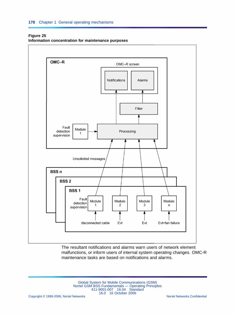
178 Chapter 1 General operating mechanisms
Figure 25Information concentration for maintenance purposes
The resultant notifications and alarms warn users of network elementmalfunctions, or inform users of internal system operating changes. OMC-Rmaintenance tasks are based on notifications and alarms.
Global System for Mobile Communications (GSM)Nortel GSM BSS Fundamentals — Operating Principles
411-9001-007 16.04 Standard16.0 16 October 2006
Copyright © 1999-2006, Nortel Networks Nortel Networks Confidential
.
1.13 Fault management 179
The OMC-R Fault Management function includes notification managementand resultant alarm management.
• notification management:
— unsolicited message reception
— unsolicited message translation into notifications
— notification storage in a database
— notification log processing
• alarm management:
— filtering notifications to avoid redundancy
— alarm generation: A notification cannot trigger an alarm (theconditions in which alarms are triggered are defined in theconfiguration and can be modified by users).
— alarm storage in a database: The list of ongoing alarms and thecleared alarms.
— current alarm processing: display, acknowledge, cease, purge, andprint
— ceased alarm processing: display, purge, and print
— alarm counter and relay management
1.13.2.1 Management objectsA log object managed by the OMC-R agent describes the way in whichfaults collected on the OMC-R agent disks are stored. The OMC-R agentcreates restored log type objects whenever a fault file is restored to disk.
The mdWarning objects allow users to control the conditions in which BSSobservation counter threshold crossing and excessive error rate eventsare handled.
Six efd objects managed by the OMC-R manager allow users to filter thetypes of alarms that are fed back:
• efdAlarm: CommunicationAlarm, EnvironmentalAlarm,EquipmentAlarm, ProcessingErrorAlarm, and QualityOfServiceAlarmnotifications
• efdConfiguration: parameterValueChange, ObjetCreation, andObjetDeletion notifications
• efdStateChange: StateChange notifications
• efdObs: CommunicationAlarm notifications (observationFile Readyand mdScanReport) related to observation message processing andmanaged by the Performance Management function
Global System for Mobile Communications (GSM)Nortel GSM BSS Fundamentals — Operating Principles
411-9001-007 16.04 Standard16.0 16 October 2006
Copyright © 1999-2006, Nortel Networks Nortel Networks Confidential
.
180 Chapter 1 General operating mechanisms
• efdTrace: CommunicationAlarm notifications (traceFileRead y andtraceReport) related to trace message processing and managed by thePerformance Management function
• efdSpecificNotif: beginning and end of specific action notifications sentby the OMC-R agent, such as end of BDA buiding, end of audit. Thesemessages are displayed in the session logs.
The mdWarning, log, and efd objects are functional objects related to themd object. They have numerous instances.
1.13.3 Unsolicited message managementThe Fault Management function manages the following:
• unsolicited messages sent by the BSC
• unsolicited messages sent by OMC applications
1.13.3.1 Unsolicited messages sent by the BSCThe unsolicited messages are stored in circular files on BSC disks. Eachmessage contains the following:
• date and time the message was sent (BSS reference)
• message type
• identity of the logical entity (object) responsible for the message
• specific information (type and number of BTS equipment, type andnumber of BSC processor, etc.)
In case of BSS/OMC-R link outage, the files must be able to store all themessages sent in a 24-hours period.
When the link is restored, the messages contained in these files areforwarded to the OMC-R agent. Messages may be lost if the maximumcircular file capacity is reached or if the disks are reset when the BSCis restarted.
The BSS unsolicited messages handled by the Fault Management functionare as follows:
• software anomaly
• hardware fault
• warning
• state change
• parameter value change
• restart
• BIST result
Global System for Mobile Communications (GSM)Nortel GSM BSS Fundamentals — Operating Principles
411-9001-007 16.04 Standard16.0 16 October 2006
Copyright © 1999-2006, Nortel Networks Nortel Networks Confidential
.
1.13 Fault management 181
• purge
Their functions are as follows:
• The software anomaly messages inform users of anomalies detectedin software applications running on BSC processing chains. They aregenerated by bsc objects.
• The hardware fault messages inform users of equipment failures andmalfunctions. They are generated by bsc, bsc e3, bts, btsSiteManager,pcmCircuit, tcu e3, transceiver, transceiverEquipment, transcoder, andtranscoderBoard objects.
• The warning messages inform users of network operating changes,such as reference clock resetting, short-lived faults, inconsistenciesdetected on A, Abis, and Ater interfaces, etc. They are generated by bsc,bsc e3, bts, btsSiteManager, lapdLink, signallingLink, signallingLinkSet,signallingPoint, tcu e3, transceiverEquipment, transcoder, andtranscoderBoard objects.
• The state change messages inform users of object operationalStatechanges that may be due to a change in internal system operatingconditions or changes to the same or another object administrativeState.They are generated by bsc, bsc e3, bts, btsSiteManager, lapdLink,pcmCircuit, signallingLink, tcu e3, transceiver, transceiverEquipment,transcoder, transcoderBoard, and xtp objects.
• The parameter value change messages inform users of spontaneouschanges to managed BSC object parameter values: dynamicre-allocation, state change, etc. They are generated by bsc objects.
• The restart messages inform users
— For BSC 12000HC
that the BSC 12000HC has been reconfigured because of an internalproblem or in response to a BSC 12000HC chain suicide request.They are generated by bsc 2G objects:
– restart after a TRAP or NMI (Non Maskable Interrupt) due to anMPU, OMU, SICD 8V, or CCS7 processor in the BSC
– suicide request triggered by a board and generated by the ECIor the SICX board in the BSC 12000HC
– suicide triggered by a BSC 12000HC application and generatedby the OMU processor in the BSC 12000HC
BSC 12000HC chain suicide may also be triggered by users.
— For BSC 3000
Global System for Mobile Communications (GSM)Nortel GSM BSS Fundamentals — Operating Principles
411-9001-007 16.04 Standard16.0 16 October 2006
Copyright © 1999-2006, Nortel Networks Nortel Networks Confidential
.
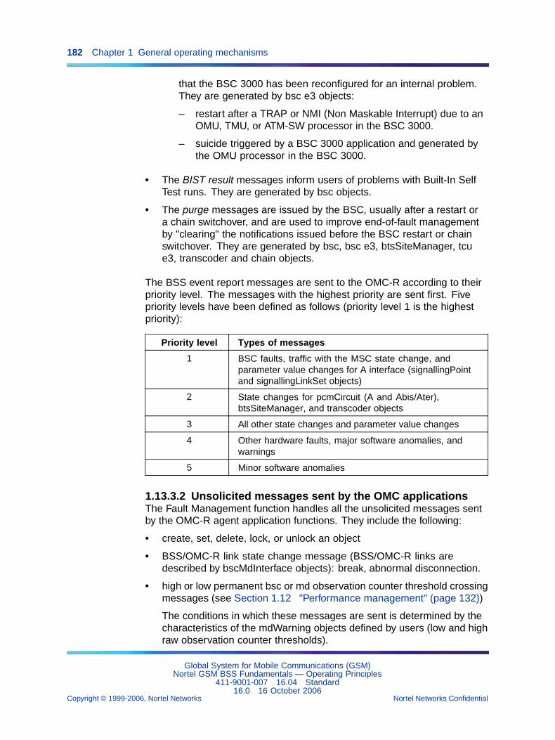
182 Chapter 1 General operating mechanisms
that the BSC 3000 has been reconfigured for an internal problem.They are generated by bsc e3 objects:
– restart after a TRAP or NMI (Non Maskable Interrupt) due to anOMU, TMU, or ATM-SW processor in the BSC 3000.
– suicide triggered by a BSC 3000 application and generated bythe OMU processor in the BSC 3000.
• The BIST result messages inform users of problems with Built-In SelfTest runs. They are generated by bsc objects.
• The purge messages are issued by the BSC, usually after a restart ora chain switchover, and are used to improve end-of-fault managementby "clearing" the notifications issued before the BSC restart or chainswitchover. They are generated by bsc, bsc e3, btsSiteManager, tcue3, transcoder and chain objects.
The BSS event report messages are sent to the OMC-R according to theirpriority level. The messages with the highest priority are sent first. Fivepriority levels have been defined as follows (priority level 1 is the highestpriority):
Priority level Types of messages
1 BSC faults, traffic with the MSC state change, andparameter value changes for A interface (signallingPointand signallingLinkSet objects)
2 State changes for pcmCircuit (A and Abis/Ater),btsSiteManager, and transcoder objects
3 All other state changes and parameter value changes
4 Other hardware faults, major software anomalies, andwarnings
5 Minor software anomalies
1.13.3.2 Unsolicited messages sent by the OMC applicationsThe Fault Management function handles all the unsolicited messages sentby the OMC-R agent application functions. They include the following:
• create, set, delete, lock, or unlock an object
• BSS/OMC-R link state change message (BSS/OMC-R links aredescribed by bscMdInterface objects): break, abnormal disconnection.
• high or low permanent bsc or md observation counter threshold crossingmessages (see Section 1.12 "Performance management" (page 132))
The conditions in which these messages are sent is determined by thecharacteristics of the mdWarning objects defined by users (low and highraw observation counter thresholds).
Global System for Mobile Communications (GSM)Nortel GSM BSS Fundamentals — Operating Principles
411-9001-007 16.04 Standard16.0 16 October 2006
Copyright © 1999-2006, Nortel Networks Nortel Networks Confidential
.
1.13 Fault management 183
• abnormally high error rate messages from the same BSS entity
The conditions in which these messages are sent is determined by thecharacteristics of the mdWarning object defined by users (maximumerror rate, accounting reference period).
• OMC-R malfunction messages.The OMC-R considers itself a networkelement and manages its own faults in the same way as the otherentities (see NTP < 032 >).
Disk, memory, database (BDE) rebuilding operation, etc., areresponsible for software or hardware faults.
The OMC-R defense function preprocesses these messages and maydecide not to forward the information to the Fault Management function.
• purge messages
These messages are issued by the OMC-R agent, under the followingconditions:
— defensive purge: When the number of correlated notifications for agiven BSC reaches a threshold set by configuration, the OMC-Ragent deletes the oldest notifications to avoid disk overflowing.
— daily purge: Everyday, the OMC-R agent activates a process topurge the correlated notifications which are more than N days old,where N is set in static configuration data.
1.13.3.3 NotificationsThe unsolicited messages are translated into notifications for user purposes.
All unsolicited messages resulting in an alarm notification are identified by afault number which is specific to the message type: a given fault numberis only contained in messages of a given type.
All notifications are given a specific serial number that allows users toidentify them. The message also includes the date/time when the eventmessage was sent and the date/time of delivery to the OMC-R manager.
The OMC-R decodes the object identifiers contained in the messages. TheOMC-R operations database is read to obtain the information supplied bythe Configuration Management function.
The BSC 12000HC and BSC 3000 architectures provide information on theBSC hardware configuration, such as the number of the equipment, theprocessor or the chain, that allows the defective board to be located.
More than one notification may be issued in response to an unsolicitedmessage. Each notification contains the following information:
• Common information:
— identification number of the notification on the OMC-R manager
Global System for Mobile Communications (GSM)Nortel GSM BSS Fundamentals — Operating Principles
411-9001-007 16.04 Standard16.0 16 October 2006
Copyright © 1999-2006, Nortel Networks Nortel Networks Confidential
.
184 Chapter 1 General operating mechanisms
— identification number of the notification on the OMC-R agent whenthe message is issued by a BSS or the OMC-R agent
— notification type
— identification number of the BSC when the message is issued bya BSS
— identification number of the OMC-R agent when the message isissued by the OMC-R agent
— reference number and name of the machine (server or workstation)when the message is issued by the OMC-R manager
— reference number of the task when the message is issued by theOMC-R manager
— class and instance of the concerned object
— date and time of unsolicited message transmission
— date and time of notification reception on the OMC-R manager
• Alarm notification:
— specific problems. This parameter includes two fields:
– fault number
– associated cause(s)
— probable cause = numerical value of the ISO probableCause field
— perceived severity. It indicates how it is perceived that the capabilityof the managed object has been affected; "cleared" indicates theclearing of one or more previous faults.
— model, type, and equipment number when the message is issuedby a BSC or a BTS
— location of the faulty equipment (cabinet, rack, etc.) when themessage is issued by a BSS
— additional information such as post-mortem information, identifier ofthe BSC 12000HC chain or the BSC 3000 OMU involved, identifierof the observation counter involved, or identifier of the mdWarningobject involved
— additional information such as the information for the operator(PLMNO) and for the manufacturer (MANU)
• State change notification:
— source indicator
Global System for Mobile Communications (GSM)Nortel GSM BSS Fundamentals — Operating Principles
411-9001-007 16.04 Standard16.0 16 October 2006
Copyright © 1999-2006, Nortel Networks Nortel Networks Confidential
.
1.13 Fault management 185
— state parameter values such as administrativeState,operationalState, availabilityStatus, standbyStatus, usageState,controlStatus, and upgradeStatus
• parameter value change notification:
— source indicator
— list of the parameters involved and their values when the messageis issued by a BSS
1.13.3.4 Notification correlation mechanismThe notification correlation mechanism provides an alarm notification whichcontains a list of identifiers of the notifications that are considered to becorrelated.
Two notifications are said to be correlated if they contain the same valuesof the following information items:
• class and instance of the related managed object
• type and number of the processor involved (when appropriate)
• type and number of the equipment involved (when appropriate)
• identifier of the chain involved (when appropriate)
• identifier of the related mdWarning (when appropriate)
• fault number
• MD cause when the event is from an OMC application
The alarm notifications issued by this process have a severity parameterset to "cleared".
1.13.3.5 Notification logsSystem notification log The OMC-R automatically saves notifications inreal time in a system notification log.
The system notification log contains all the notifications that aregenerated except the notifications that are hidden to the operator. Thelist of such rejected notifications is statically configurable in the file/OMC/base/config/fmMgr.cfg, parameter listCodanosReject (as well as foruser notification log). It is kept up to date and to avoid saturation, the oldestmessages are progressively deleted to make room for the more recentmessages. The log storage capacity is set in the static configuration tohold seven days’ notifications.
Authorized users can consult the log in a dedicated log consultation windowduring work sessions. The notifications are filtered according to the zone ofinterest defined in the connected user’s profile.
Global System for Mobile Communications (GSM)Nortel GSM BSS Fundamentals — Operating Principles
411-9001-007 16.04 Standard16.0 16 October 2006
Copyright © 1999-2006, Nortel Networks Nortel Networks Confidential
.
186 Chapter 1 General operating mechanisms
The entire log or selected portions can be consulted. The following is apartial list of selection criteria:
• messages of a given type
• messages containing given fault numbers
• messages sent by a type of BSC processor, BTS equipment, or object(the user can also select a given processor, equipment, or particulartype of object)
• messages sent or received in a given period of time
• notifications with given serial numbers
One or more criteria can be selected. Without criteria, all the notificationsrelated to entities in the user’s zone of interest are displayed. The displayednotifications can be printed.
User notification log A user notification log is made available to everyuser during a work session in a dedicated log consultation window.
This log only contains the notifications issued after the window was openedin response to the unsolicited messages sent by the entities defined in thezone of interest of the connected user.
Notifications can be selected with the same criteria as above. The displayednotifications can be printed.
A user notification log is deleted when the consultation window is closed.
User state change log Object state changes are notified to the user in adedicated log, the user state change log.
This log contains all Q3 notifications of StateChange type resulting fromobject locking/unlocking user commands (administrativeState changes) orunsolicited state change messages (operationalState and availabilityStatuschanges).
Each notification is translated into a specific message stored in the log thatcontains the following information:
• date and time of state change occurrence
• class of the concerned object
• object administrativeState, operationalState, availabilityStatus,usageState, controlStatus, upgradeStatus, and standbyStatusparameter values
• identity of the concerned object
Global System for Mobile Communications (GSM)Nortel GSM BSS Fundamentals — Operating Principles
411-9001-007 16.04 Standard16.0 16 October 2006
Copyright © 1999-2006, Nortel Networks Nortel Networks Confidential
.
1.13 Fault management 187
A user state change log is made available to every user during a worksession in a dedicated log consultation window.
The log only contains state change messages related to the entities definedin the zone of interest of the connected user. The window contents arerefreshed in real time.
A user state change log is deleted when the session ends.
1.13.4 Alarm management1.13.4.1 Alarm triggering mechanismsA notification contains a certain amount of information. It is identified by afault number specific to the associated unsolicited message type. It is alsoidentified by hardware fault, state change, threshold crossing, etc.
If the Fault Management function recognizes start-of-fault information ina message, an alarm may be triggered. The alarm message is sent topinpoint a specific problem and to warn users that action is required.
The following Q3 notifications may trigger an alarm:
• CommunicationAlarm (restart, warning)
• EnvironmentalAlarm (equipment environment alarm)
• EquipmentAlarm (hardware fault)
• ProcessingErrorAlarm (software anomaly, BIST result)
• QualityOfServiceAlarm (threshold crossing, error rate)
• StateChange (state change)
Start-of-alarm conditions are defined in the configuration and partiallydepend on the type of Q3 notification issued. An alarm is only triggeredwhen the defined conditions are met.
1.13.4.2 Alarm clearing mechanismsAn alarm is cleared if the OMC-R receives an end-of-fault messagemeaning that the Fault Management function considers that the fault hasbeen cleared and the defective element is now operating correctly.
Specific end-of-alarm conditions are defined in the configuration. They mustbe consistent with the start-of-alarm conditions.
If, for example, a start-of-alarm message is issued when an object statechanges to disabled (for possible causes, refer to the operationalStateentries in NTP < 124 >), an end-of-alarm message must be sent when theobject state changes back to enabled.
In some conditions, the end of fault is not detected and no correspondingmessage is generated.
Global System for Mobile Communications (GSM)Nortel GSM BSS Fundamentals — Operating Principles
411-9001-007 16.04 Standard16.0 16 October 2006
Copyright © 1999-2006, Nortel Networks Nortel Networks Confidential
.
188 Chapter 1 General operating mechanisms
The event(s) that trigger(s) end-of-fault messages may not be delivered tothe OMC-R. For example, to repair a defective equipment, the equipmentis taken out of service and the object on the level above that describes thedefective equipment may also be taken out of service. After repairs, theequipment and the object on the level above are both returned to service.However, some of the information may no longer be available and theend-of-fault message is not generated.
To overcome this problem, alarms can be ceased in two ways, automaticallyby the system or manually by the user.
• automatic alarm ceasing when the following occurs:
— end-of-fault message received. All alarms activated on the samecriteria and concerning the same object or equipment are ceased.
— purge message received. All alarms resulting from correlatednotifications that correspond to the criteria defined in the purgemessage are ceased.
— object deletion or unlocking. All alarms related to the object areceased (the OMC-R assumes that the problem has been solved).The following also occur:
– All alarms related to transceiver and channel objects dependingon an unlocked bts object are ceased.
– For alarms raised by synthetic counters which are automaticallycleared after an unlock command, then in accordance withcommon behavior, the alarm will be immediately generated againif the fault is still present, that is, if the counter is still above (orbelow) the threshold at the moment of the purge.
— BSS observation counter threshold change. All alarms related to thecounter occurrence are ceased if the new threshold value returnsthe counter to normal operating mode.
— All alarms are ceased by the purge mechanism if the correspondingend-of-fault message is not received or generated within 30 days.
• manual alarm ceasing by users:
A user can cease alarms in one of the following ways:
— cease selected alarms
— cease selected object alarms
— cease whole subtree (md, bsc, etc.) alarms
Global System for Mobile Communications (GSM)Nortel GSM BSS Fundamentals — Operating Principles
411-9001-007 16.04 Standard16.0 16 October 2006
Copyright © 1999-2006, Nortel Networks Nortel Networks Confidential
.
1.13 Fault management 189
1.13.4.3 Alarm state detecting mechanismsThe conditions in which alarms are triggered or ceased are defined inconfiguration data and depend on the type of the Q3 notification issued.Note that all alarms can be ceased by users or on system time-out. Onlythe conditions specific to each notification type are described below.
• EquipmentAlarm notification:
— An alarm may be generated after a failure that triggers this type ofmessage sending.
— The alarm is ceased if one of the following occurs:
– An end-of-alarm message is received (message generation isonly guaranteed when the fault is detected by ALA boards inBSC).
– The defective object is deleted or unlocked.
– The defective object depends on an unlocked object: transceiverand channel objects.
• CommunicationAlarm notification:
— An alarm may be generated if the system operating conditions areseverely degraded.
— This type of alarm is only ceased on time-out.
• StateChange notification:
— An alarm may be generated if an object has changed into an alarmgenerating state.
— The alarm is ceased on receipt of an end-of-alarm messageindicating that the object has changed out of an alarm generatingstate.
The list of alarm generating states varies according to the object.As a general rule, an alarm is generated if the object changesto "disabled/{dependency}" or "disabled/{failed}" state when itsadministrativeState is "unlocked". It is ceased when its operationalStateis "enabled" or its administrativeState is "locked" (see operationalStateentries in NTP < 124 >).
• ProcessingErrorAlarm notification:
— An alarm may be generated when this message is received.
— This type of alarm can only be ceased by users or on time-out.
• QualityOfServiceAlarm notification:
— threshold crossing:
Global System for Mobile Communications (GSM)Nortel GSM BSS Fundamentals — Operating Principles
411-9001-007 16.04 Standard16.0 16 October 2006
Copyright © 1999-2006, Nortel Networks Nortel Networks Confidential
.
190 Chapter 1 General operating mechanisms
– An alarm may be generated when a BSS permanent observationcounter crosses a high or low threshold.
– The alarm is ceased when the end-of-alarm message isreceived, indicating that the counter is operating normally.
The operator can set threshold values dynamically for eachobservation counter occurrence. If a counter alarm was reportedand the newly read value is no longer above or below the definedthreshold, an end-of-fault message is automatically generated.
The threshold crossing detection mechanism is described in theSection 1.12 "Performance management" (page 132).
— excessive error rate:
– An alarm may be generated if the OMC-R detects an error rateabove the maximum reference threshold over a given referenceperiod and from any BSS entity.
– An end-of-alarm message is generated when the rate dropsbelow the minimum threshold for a given minimum accountingtime.
The operator configures the thresholds and reference periodsdynamically. They may vary between BSSs. The accounting time is setat one minute in the static configuration.
In order to give the operator some time to react when this type ofnotification is received, the alarm state is maintained over a 15-minutesperiod by the OMC-R agent. At the expiration, a new period is startedand the following apply:
— If an end-of-fault message is received during this period, anend-of-fault notification is generated.
— If no new notification is received during this period, the state of theentity is controlled at the end of the period and the OMC-R agenttakes the appropriate actions.
If the associated mdWarning object is locked, the system does nottake any alarm change state into account.
1.13.4.4 Alarm generating mechanismsIf the alarm triggering conditions are met after checking, the OMC-R allowsusers to decide whether to generate the alarm and define the type of action(severity) required if the alarm is generated (the alarm is then called acurrent or ongoing alarm).
Global System for Mobile Communications (GSM)Nortel GSM BSS Fundamentals — Operating Principles
411-9001-007 16.04 Standard16.0 16 October 2006
Copyright © 1999-2006, Nortel Networks Nortel Networks Confidential
.
1.13 Fault management 191
When a current alarm is generated, the OMC-R generates an alarmmessage. These messages are automatically saved in chronological orderand real time in a dedicated log, the list of ongoing alarms.
When an alarm is ceased automatically or manually, the correspondingmessage is deleted from the list of ongoing alarms and stored in anotherdedicated log, the cleared alarm log.
1.13.5 Alarm criteriaThe function of the alarm criteria is to determine whether the notificationsthat are issued should result in alarms.
The OMC-R provides users with alarm criteria configurations that allow toassociate user alarms with BSS or OMC-R faults.
There are three alarm criteria configurations. Each configuration definesspecific conditions in which notifications are handled. The following apply:
• The OMC-R Fault Management function uses one of the configurationsto manage the notifications, it is called the active alarm handlingconfiguration.
• MMI commands on the omc object allow users to display and set theactive alarm handling configuration at any time.
1.13.5.1 Manufacturer and operator alarm criteriaThere are two types of alarm criteria:
• Some alarm criteria are defined by the manufacturer and can only belocked or unlocked by the operator (they cannot be deleted or editedby the operator).
• Other alarm criteria can be modified by the operator. The value of thealarm criterion identifier determines whether it is a "manufacturer" or an"operator" alarm criterion. These values are given in the descriptionof the alarm criteria identifier in Section 1.13.5.3 "Definition of alarmcriteria" (page 192).
All alarm criteria are stored in the directory named /OMC/data/fm.
Alarm criteria files are not an interface for alarm criteria modifications. Allactions with alarm criteria should be done through the MMI browser.
1.13.5.2 Operating configurationsThree alarm operating configurations are supplied, they are named daytime,nighttime and specific.
• "/OMC/data/fm/fmCritAlaDay.dat" - file in which the daytime configurationis stored.
Global System for Mobile Communications (GSM)Nortel GSM BSS Fundamentals — Operating Principles
411-9001-007 16.04 Standard16.0 16 October 2006
Copyright © 1999-2006, Nortel Networks Nortel Networks Confidential
.
192 Chapter 1 General operating mechanisms
• "/OMC/data/fm/fmCritAlaNight.dat" - file in which the nighttimeconfiguration is stored.
• "/OMC/data/fm/fmCritAlaPart.dat" - file in which the specific configurationis stored.
The network operator defines the operating configurations in agreementwith the manufacturer. They can be modified during work sessions.
The names given to the configurations are used to differentiate them. Usersmay activate any configuration at any time, but only one configuration canbe activated at a time. Users may create a job that automatically switches toa given configuration at defined dates and times (see Section 1.18 "Userfacilities" (page 250)).
When the OMC-R starts up or after the active server switches over, theOMC-R activates the configuration corresponding to the time at whichstart-up or switchover occurred. It is the only occasion when the "time" inthe configuration name is significant:
• The daytime configuration is activated if the operation is performedbetween 9 a.m. and 6 p.m. (this period of time can be staticallyreconfigured).
• The nighttime configuration is activated if the operation is performedbetween 6 p.m. and 9 a.m. (this period of time can be staticallyreconfigured).
By definition, an operator alarm criterion is simultaneously created in thethree operating configurations with identical management parameters,except for the type of action that can differ from one configuration to theother.
These configurations give users some flexibility in managing the alarms.One configuration could, for example, be used during weekday workinghours, the second at night when traffic conditions are different, and the thirdon statutory holidays or week ends when traffic conditions are differentagain.
1.13.5.3 Definition of alarm criteriaAn alarm configuration is a table that defines the list of criteria for handlingthe faults according to their type and source.
Each criterion is identified by a unique number in the table and is describedby a list of associated parameters as follows:
• alarm criteria identifier:
— Alarm criteria with identifiers < 100000 are pre-defined. They arealso OMC-R configuration and cannot be deleted or changed by
Global System for Mobile Communications (GSM)Nortel GSM BSS Fundamentals — Operating Principles
411-9001-007 16.04 Standard16.0 16 October 2006
Copyright © 1999-2006, Nortel Networks Nortel Networks Confidential
.
1.13 Fault management 193
the user. However, it is possible to lock or unlock these criteria (bychanging the administrative state).
— Alarm criteria with identifiers >= 100000 can be added, edited anddeleted by the user without any restriction. These are also known as"operator" alarm criteria.
ATTENTIONThe total number of alarm criteria must not exceed 1000 in V16.0.
• associated parameters:
— type of configuration (manufacturer or operator) where the criterionis defined. Note that an operator criterion simultaneously exists inthe three operating configurations.
— type of the notifications handled by the criterion. There are twopossibilities as follows:
– all alarm notifications (CommunicationAlarm, Environ-mentalAlarm, EquipmentAlarm, ProcessingErrorAlarm,QualityOfServiceAlarm)
– all state change notifications (StateChange)
— scope of the criterion = subset of network objects to which thecriterion applies. There are four possibilities as follows:
– one object instance
– all object instances of a given class
– all objects in a given subtree
– all objects
— type of the BSC 12000HC, BTS or BSC 3000 controlling the subsetof network elements to which the criterion applies
— criterion state indicator for analysis purposes: An active criterion(unlocked state) is analyzed when the notification satisfies thecriterion, an inactive criterion (locked state) is ignored.
— action to take when the notification satisfies the criterion (no alarm,immediate alarm, deferred alarm, alarm with no action)
— if no counter is associated with the criterion:
– start-of-alarm condition = logical expression that defines thetype of notifications to which the criterion applies (for example:severity = MAJOR & fault number = 1067) and which activatesan alarm when TRUE
Global System for Mobile Communications (GSM)Nortel GSM BSS Fundamentals — Operating Principles
411-9001-007 16.04 Standard16.0 16 October 2006
Copyright © 1999-2006, Nortel Networks Nortel Networks Confidential
.
194 Chapter 1 General operating mechanisms
– end-of-alarm condition = logical expression that depends on thetype of notifications to which the criterion applies and whichallows to cease the alarm
— if a counter is associated with the criterion:
– counter level consulting condition = logical expression
– synthetic fault number to assign to the alarm [39500 to 39549]
– alarm duration
– accounting reference period
– high threshold level triggering a start-of-alarm message
– low threshold level triggering an end-of-alarm message
The configuration may therefore contain a criterion xxx partnered with anotification whose source is any object instance of the bts class with animmediate action alarm category, and a criterion zzz partnered with thesame type of notification whose source is any object instance of anotherclass with a deferred action alarm category.
In the same way, a criterion xxx partnered with a notification whose sourceis any object instance of the bts class may activate an immediate alarmin the daytime configuration, activate a deferred alarm in the nighttimeconfiguration, and not activate any alarm in the specific configuration.
1.13.5.4 Notification processingAlarm criteria are organized as two groups which are the following:
• the group of criteria that request to activate an alarm (action = immediatealarm, deferred alarm, no-action alarm)
• the group of criteria that do not request to activate an alarm (action= no alarm)
Within each group, alarm criteria are organized as coherent sub-groupscalled "families". By definition, a family is made of all criteria with the samescope and applying to the same type of notification.
When a notification is received, the OMC-R analyzes its type and source.Then, the analysis from the alarm criteria configuration that is active atthat time is as follows:
• The search for the alarm criterion to apply to the received notificationstarts with the group of criteria that request to activate an alarm. If nocriterion in that group is found, the search goes on with the group ofcriteria that do not request to activate an alarm.
Global System for Mobile Communications (GSM)Nortel GSM BSS Fundamentals — Operating Principles
411-9001-007 16.04 Standard16.0 16 October 2006
Copyright © 1999-2006, Nortel Networks Nortel Networks Confidential
.
1.13 Fault management 195
Therefore if two criteria apply to the same fault number, with one thatrequests to activate an alarm and the other that does not request toactivate an alarm, then the former is applied and the notifications withthat fault number will always activate an alarm.
• Within a given family, criteria are analyzed in ascending order.
Therefore if two criteria in a same family can apply to the receivednotification and request to activate an alarm, the one with the smallestidentifier will be applied.
• The search goes on until the most specific criterion that can apply tothe received notification is found.
Therefore if two criteria in two different families can apply to the receivednotification, with one that applies to the instance of the object involvedand the other to the class of the object involved, the former will beapplied.
When the most suitable criterion is found, according to the rules definedabove, the analysis stops and the OMC-R executes the action defined bythat criterion.
Notes:
• Inactive criteria are not analyzed when a notification is received.
• The priority of alarm triggering criteria over non-alarm triggering criteriais a default configuration data. It can be reversed by reconfiguration.
1.13.5.5 Table of alarm configuration criteriaThe detailed structure of the alarm criterion configuration table is describedin NTP < 006 >.
1.13.6 Man-machine commands1.13.6.1 Alarm managementThe Current alarm list windows The MMI "Current alarm list" windowsallow users to display and manage ongoing alarms.
A "Current alarm list" window is opened from an "OMC-R Browser" windowby selecting one of the Show options of the Fault menu. Alarm messagesare displayed by manually selecting network elements in the "OMC-RBrowser" window.
In a "Current alarm list" window, ongoing alarms are displayed as a table.Each alarm is described on one line which contains the following information:
• identification number of the alarm
• identification of the object that is the source of the alarm
• date and time of alarm creation on the OMC-R
Global System for Mobile Communications (GSM)Nortel GSM BSS Fundamentals — Operating Principles
411-9001-007 16.04 Standard16.0 16 October 2006
Copyright © 1999-2006, Nortel Networks Nortel Networks Confidential
.
196 Chapter 1 General operating mechanisms
• type of the associated Q3 notification
• alarm severity and acknowledgment state
Selecting an alarm in the table leads to display the associated alarmmessage in the window, as it is stored in the OMC-R list of ongoing alarms.
Various buttons allow users to filter the alarms to display.
Only the alarm messages related to network elements belonging to thezone of interest defined in the connected user’s or off-line terminal profileare displayed.
The window contents can be permanently refreshed on a new alarmoccurrence from a selected network element, acknowledgement, automaticor manual ceasing of current alarms, or the display can be frozen. Twospecial buttons allow users to switch from a permanently refreshed state toa frozen state or vice versa.
The "Current alarm list" windows are partnered with an output class. Referto the Section 1.16 "Security management" (page 231).
Alarm messages An alarm message contains the following information:
• a serial number that identifies the alarm in time. At a given time, anumber is allocated to one alarm. This number is increased whenevera new alarm is received.
• the serial number assigned to the notification responsible for the alarmmessage
• date and time at which the notification was sent: BSS reference timefor unsolicited messages sent by the BSS, OMC-R reference time formessages sent by the OMC applications
• date and time at which the notification was received (OMC-R agentreference time)
• type of the corresponding Q3 notification
• fault number that identifies the kind of fault and its cause (this code isthe unsolicited message code if the BSS sent the message)
• alarm severity: critical (immediate action), major (deferred action), orminor (no action required)
• alarm title
• identity and location of the object and/or equipment responsible for thealarm (meaning the element that detected the problem and that is notnecessarily the defective element)
Global System for Mobile Communications (GSM)Nortel GSM BSS Fundamentals — Operating Principles
411-9001-007 16.04 Standard16.0 16 October 2006
Copyright © 1999-2006, Nortel Networks Nortel Networks Confidential
.
1.13 Fault management 197
• alarm acknowledgement state. An alarm is generated inunacknowledged state. It may subsequently be acknowledged by auser (see below).
• if the alarm is acknowledged, the identity of the acknowledger, eitheran OMC-R user (manual acknowledgement) or the OMC-R agent(automatic acknowledgement)
• if the alarm is ceased:
— date and time at which the corresponding notification was sent
— identity of the clearer, either a user (manual ceasing) or the OMC-Ragent (automatic ceasing)
Alarm messages are stored in chronological order and real time in twodedicated OMC-R logs that users may consult: the list of ongoing alarmsand the cleared alarm log.
• list of ongoing alarms
The list of ongoing alarms contains all the current alarm messages.
The list is kept up to date: new alarm occurrence, manual or automaticacknowledgement, manual or automatic ceasing.
The list of ongoing alarms is never purged and is always available tousers.
• cleared alarm log
When an alarm is ceased, either manually or automatically, thecorresponding message disappears from the list of ongoing alarms andis stored in the cleared alarm log.
The OMC-R automatically and progressively purges ceased alarms fromthe log. To avoid saturation, the oldest alarm messages are deleted tomake room for the most recent.
Acknowledging alarms An alarm is acknowledged when the user attendsto it. This does not mean that the cause of the alarm has been cured, butthat the user is aware of the problem.
Alarms can be acknowledged by MMI commands, either from an "OMC-RBrowser" window (alarms related to a selected network element or subtree),or from an "Alarms monitor" window (selected alarms). The list of ongoingalarms is updated in the OMC-R, as well as all the concerned windowsthat are opened.
Only an authorized user can manually acknowledge alarms. The right toacknowledge alarms is determined by the output domain defined in theconnected user’s profile.
Global System for Mobile Communications (GSM)Nortel GSM BSS Fundamentals — Operating Principles
411-9001-007 16.04 Standard16.0 16 October 2006
Copyright © 1999-2006, Nortel Networks Nortel Networks Confidential
.
198 Chapter 1 General operating mechanisms
Ceasing alarms Alarms can be ceased by MMI commands, either froman "OMC-R Browser" window (alarms related to a selected network elementor subtree), or from an "Current alarm list" window (selected alarms). Theceased alarm messages are deleted from the list of ongoing alarms andstored in the cleared alarm log. All the concerned windows that are openedare updated as well.
Only an authorized user can manually cease alarms. The right to ceasealarms is determined by the output domain defined in the connected user’sprofile.
1.13.6.2 Log consultationUsers can display all or selected notifications stored in the systemnotification log, or all or selected alarm messages stored in the clearedalarm log, during a work session, and within the limits of the zone of interestof the connected user’s profile.
These logs can be accessed by selecting the matching option of the Faultmenu in an "OMC-R Browser" window. The information is displayed in a logconsultation window that opens on the terminal screen.
The selection criteria applying to both logs are as follows:
• messages with a given fault number
• messages with given serial numbers
• messages from a type of BSC 12000HC processor, BSC 3000processor, BTS equipment, or object (users can also choose aprocessor, equipment, or an object of a given type)
• messages related to the notifications sent or received at a given time orin a given interval of time
The following criterion can be applied to cleared alarms only:
• alarm messages ceased by a given user
1.13.6.3 Off-line alarm managementThe graphic elements shown in an "OMC-R Browser" window on anymanagement level are filtered according to the zone of interest defined inthe profile of the terminal that is used and represent the set of networkelements that users can monitor using that terminal outside a work session.
The following occurs in this context:
• Only the alarms resulting from the notifications sent by the entitiesdefined in the zone of interest defined in the terminal’s profile aredisplayed in an "Current alarm list" window.
• Acknowledge and cease alarm commands are rejected.
Global System for Mobile Communications (GSM)Nortel GSM BSS Fundamentals — Operating Principles
411-9001-007 16.04 Standard16.0 16 October 2006
Copyright © 1999-2006, Nortel Networks Nortel Networks Confidential
.
1.13 Fault management 199
1.13.6.4 Alarm criteria managementAlarm criteria manager window The MMI "Alarm criteria manager"window allows users to display and manage alarm criteria.
This window is opened from any "OMC-R Browser" window by selecting theAlarm criteria manager option in the Fault menu with the mouse.
The "Alarm criteria manager" window is partnered with an output class.Refer to the Section 1.16 "Security management" (page 231).
Alarm criteria configuration management Alarm criteria defined in thethree alarm criteria configurations are displayed as a table in the "Alarmcriteria manager" window. Each line in the table identifies an alarm criterionand each column in the table displays one of the associated parameters.
Alarm criteria are displayed in ascending numerical order by default. Theorder of display can be re-arranged by moving columns one by one to theleft or to the right. A configuration menu allows to filter the alarm criteria orassociated parameters to display at a given time.
The following commands are used for managing the alarm criteria:
• Create
This command allows to create a new alarm criterion in the threeoperating configurations at a time.
• Set
This command allows to modify the parameters of an alarm criterion inthe three operating configurations at a time.
• Delete
This command allows to remove an alarm criterion from the threeoperating configurations at a time.
• Clone
This command allows to create an alarm criterion.
A test command allows to simulate a given notification processing. Itprovides the list of the alarm criteria that would possibly be taken intoaccount if the notification were really processed by the OMC-R FaultManagement function.
ATTENTIONAlarm criteria with identifiers < 100000 cannot be deleted or changed by the user.
Global System for Mobile Communications (GSM)Nortel GSM BSS Fundamentals — Operating Principles
411-9001-007 16.04 Standard16.0 16 October 2006
Copyright © 1999-2006, Nortel Networks Nortel Networks Confidential
.
200 Chapter 1 General operating mechanisms
ATTENTIONAlarm criteria with identifiers >= 100000 can be added, edited and deleted bythe user without any restriction. See also the description of the alarm criteriaidentifier in Section 1.13.5.3 "Definition of alarm criteria" (page 192) "Definitionof alarm criteria".
Active configuration management Two commands on the omc objectshown in the "OMC-R Browser" window on OMC level are used formanaging the active alarm handling configuration.
• Display
This command displays the name of the current OMC-R alarm handlingconfiguration (day / night / specific / reference).
• Set
This command sends instructions to the OMC-R Fault Managementfunction to use the specified fault handling configuration (day / night /specific / reference).
If the requested configuration cannot be loaded, the OMC-R switches tothe reference configuration and warns the user.
The groups and families of alarm criteria are defined at that time fromthe newly loaded configuration.
1.13.7 Alarm counters and relays1.13.7.1 Alarm countersThe OMC-R manager controls alarm counters covering two managementlevels: system level and BSS level.
• At system level, three totaling counters tally the following:
— the number of ongoing, critical, unacknowledged alarms on all BSSsand OMC-R agent
— the number of ongoing, major, unacknowledged alarms on all BSSsand OMC-R agent
— the number of ongoing, minor, unacknowledged alarms on all BSSsand OMC-R agent
• At BSS level, three totaling counters tally the following:
— the number of ongoing, critical, unacknowledged alarms for the BSS
— the number of ongoing, major, unacknowledged alarms for the BSS
— the number of ongoing, minor, unacknowledged alarms for the BSS
The OMC-R manager updates all the counters whenever a new alarmoccurs or disappears, or an old alarm is acknowledged.
Global System for Mobile Communications (GSM)Nortel GSM BSS Fundamentals — Operating Principles
411-9001-007 16.04 Standard16.0 16 October 2006
Copyright © 1999-2006, Nortel Networks Nortel Networks Confidential
.
1.13 Fault management 201
Three BSS alarm counters are permanently displayed in the "Alarmsbanner" window on the terminal screen:
• When a user session is open on the terminal, the counters tally thenumber of unacknowledged ongoing critical, major, and minor alarms onthe network entities defined in the BSS zone of interest in the connecteduser’s profile.
• If no user session is open on the terminal, the alarm counters tally thenumber of unacknowledged ongoing critical, major, and minor alarms onthe network entities defined in the BSS zone of interest in the off-lineterminal profile.
1.13.7.2 Alarm relaysIn order to transfer the state of the alarm counters to an alarm monitoringpanel or a remote alarm monitoring site, each OMC-R server has a boardmanaging 64 usable relays (with other possible values of 0, 24 and 32). Thisnumber can be statically reconfigured..
• Relays 1 and 2 indicate that system counters are not zero. Relay 1 isdedicated to unacknowledged ongoing immediate action system alarms,relay 2 is dedicated to unacknowledged ongoing deferred action systemalarms.
• A relay in the range [4 to 31] indicates that a counter of unacknowledgedongoing immediate action alarms is not zero for one of the BSSsassigned to the relay.
BSS alarm relays are described by relay objects on the Man-Machineinterface. Each relay is managed independently of the other relays, asfollows:
• BSS-relay associations are dynamically managed by users.
• A BSS can be assigned to several relays at a time.
1.13.8 PCUSN interfaceThe following day-to-day PCUSN operations are also integrated in theOMC-R for an easy access. The GPRS access fault management isfully integrated within the GSM access fault management. The fault andalarm messages are forwarded in real time to the OMC-R database tobe displayed on a Man-machine Interface (MMI) workstation. The faultmanagement function treats system malfunctions and failures to supplythe elements needed for maintenance actions. This function continuouslymonitors system operations. The OMC-R stores all of the event reports itreceives from the PCU-OAM server. The incoming proprietary notificationformat from the PCUSN Network Management System (NMS) includes thefollowing information:
• NMS notification type (mandatory)
Global System for Mobile Communications (GSM)Nortel GSM BSS Fundamentals — Operating Principles
411-9001-007 16.04 Standard16.0 16 October 2006
Copyright © 1999-2006, Nortel Networks Nortel Networks Confidential
.
202 Chapter 1 General operating mechanisms
• Date and time of the PCUSN event creation (mandatory)
• PCUSN identifier number (mandatory)
• CompId (mandatory for events on PCUSN objects only)
• Fault number (mandatory)
• Start/end flag (mandatory for fault reports only)
• Operational state (mandatory for state change notifications only)
• Other notification specific data (optional)
1.14 Preventive maintenance management1.14.1 BSC 12000HC
Preventive maintenance management is based on software modules(plug-ins) containing preventive maintenance tests on BSS sub-systems.These tests can be configured, scheduled, and activated from the OMC-R.And their results can be displayed at the OMC-R. These software modulesenable the user to schedule and perform preventive maintenance operationson BSS equipment from the OMC-R.
The Preventive Maintenance management function allows to:
• schedule preventive maintenance tests (according to the user’s zoneof interest)
• execute, abort, suspend or continue tests on user demand (according tothe user’s zone of interest)
• handle test execution conflicts (through the "Scheduler" window)
• monitor test execution
• display test results in logs and sometimes in reports (depending onthe test)
• monitor test scheduling
• print and save reports
1.14.1.1 DefinitionsPreventive maintenance test A preventive maintenance test is a softwaremodule that can be installed as a plug-in without any OMC-R restart. Itcontains a test concerning one specific BSS target equipment. Log files andresult reports are produced at the end of tests, and they can be displayed,stored and retrieved from the Maintenance menu at the OMC-R.
The following preventive maintenance test is available: BSC 12000HC chainswitchover (see NTP < 034 >). This test triggers a BSC 12000HC chainswitchover, so as to check preventively that the chain switchover function isoperational and that the passive chain is operational too.
Global System for Mobile Communications (GSM)Nortel GSM BSS Fundamentals — Operating Principles
411-9001-007 16.04 Standard16.0 16 October 2006
Copyright © 1999-2006, Nortel Networks Nortel Networks Confidential
.
1.14 Preventive maintenance management 203
Target equipment A target equipment is the network element to betested, for example a BTS or a BSC 12000HC.
Activation object An activation object is related to a target equipment,and is directly interfaced with the OMC-R. If the target equipment is aBTS, or a list of BTSs, the associated activation object is the related BSC12000HC. The target equipment and the activation object can be the sameobject, for example: a BSC 12000HC.
Preventive maintenance execution window A execution window isthe time interval during which a scheduled test test can be activated, forexample: from 22:15 to 05:30.
1.14.1.2 Configuring a testA test must be configured before being executed or scheduled.
The parameters to be defined depend on the test itself:
• parameters to define specific test options (if any)
• parameters to define the selected target equipment, which can be:
— either one specific network element (for example one BSC 12000HC)
— or a list of target network elements (for example a list of BTSs).These target elements are grouped according to the relatedactivation object (generally the BSC 12000HC.
Executing a testTests can be triggered in two different ways:
• activation on user demand
• scheduled activation
If a target equipment list contains several activation objects (for exampleseveral BSC 12000HC), at execution time each couple (test, activationobject) will be executed separately:
• test abortion triggered on user demand can be done per activationobject only
• a test can be executed for one given activation object, even if otheractivation objects are busy
Activation on user demand
Method Selecting the Execute test option in the Maintenance menu ofthe "OMC-R Browser" window enables the user to trigger one preventivemaintenance test.
Global System for Mobile Communications (GSM)Nortel GSM BSS Fundamentals — Operating Principles
411-9001-007 16.04 Standard16.0 16 October 2006
Copyright © 1999-2006, Nortel Networks Nortel Networks Confidential
.
204 Chapter 1 General operating mechanisms
Requirements It is possible to execute only one test at a time peractivation object.
Scheduled activation
Requirements It is possible to execute only one test at a time peractivation object.
1.14.2 PCUSNThe preventive maintenance management functions for the Packet ControlUnit Support Node (PCUSN) are performed by the Network InformationManagement System (NIMS) PrOptimaTM Performance Management tool,which is designed by third-party Mycom International. NIMS-PrOptima usermanual PRO-SUP-USM-NOR- 041-1.04-EN describes how to use themodules offered in the NIMS-PrOptima solution including the QOS Warningsmodule, which performs Quality of Service (QoS) functions for the PCUSN.
1.15 Network graphic management1.15.1 Network display
1.15.1.1 OMC-R browser windowsThe MMI "OMC-R browser" windows present network elements. Two viewmodes exist:
• the logical mode view is based on a logical approach to show Q3 objects.
• the physical mode view is based on a physical approach to show theequipment.
The main purposes of the "OMC-R browser" windows are:
• to allow network supervision by providing synoptic real time informationabout all network elements using the logical and physical modes.
• to perform various commands by accessing to all Q3 objects and relatedcommands using the logical mode.
The OMC-R browser is made up of the 5 following areas:
• the menu bar which allows to access the services
• the network elements display area
• the navigation area which reflects the network part displayed in thenetwork element display area
• the display control area which allows to display alarms and states.Display mode (physical versus logical) control is also included in thisarea.
• The bscMdInterface display area which contains the bscMdInterface (ormatching summary) representation.
Global System for Mobile Communications (GSM)Nortel GSM BSS Fundamentals — Operating Principles
411-9001-007 16.04 Standard16.0 16 October 2006
Copyright © 1999-2006, Nortel Networks Nortel Networks Confidential
.
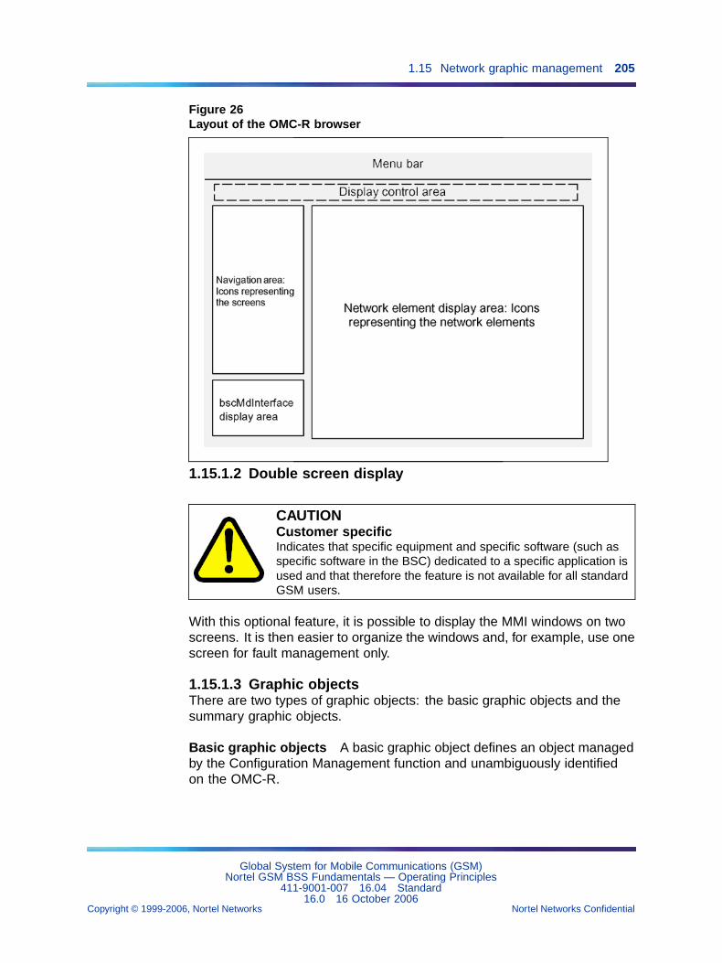
1.15 Network graphic management 205
Figure 26Layout of the OMC-R browser
1.15.1.2 Double screen display
CAUTIONCustomer specificIndicates that specific equipment and specific software (such asspecific software in the BSC) dedicated to a specific application isused and that therefore the feature is not available for all standardGSM users.
With this optional feature, it is possible to display the MMI windows on twoscreens. It is then easier to organize the windows and, for example, use onescreen for fault management only.
1.15.1.3 Graphic objectsThere are two types of graphic objects: the basic graphic objects and thesummary graphic objects.
Basic graphic objects A basic graphic object defines an object managedby the Configuration Management function and unambiguously identifiedon the OMC-R.
Global System for Mobile Communications (GSM)Nortel GSM BSS Fundamentals — Operating Principles
411-9001-007 16.04 Standard16.0 16 October 2006
Copyright © 1999-2006, Nortel Networks Nortel Networks Confidential
.
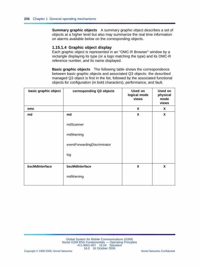
206 Chapter 1 General operating mechanisms
Summary graphic objects A summary graphic object describes a set ofobjects at a higher level but also may summarize the real time informationon alarms available below on the corresponding objects.
1.15.1.4 Graphic object displayEach graphic object is represented in an "OMC-R Browser" window by arectangle displaying its type (or a logo matching the type) and its OMC-Rreference number, and its name displayed.
Basic graphic objects The following table shows the correspondencebetween basic graphic objects and associated Q3 objects: the describedmanaged Q3 object is first in the list, followed by the associated functionalobjects for configuration (in bold characters), performance, and fault.
basic graphic object corresponding Q3 objects Used onlogical mode
views
Used onphysical
modeviews
omc X X
md md
mdScanner
mdWarning
eventForwardingDiscriminator
log
X X
bscMdInterface bscMdInterface
mdWarning
X X
Global System for Mobile Communications (GSM)Nortel GSM BSS Fundamentals — Operating Principles
411-9001-007 16.04 Standard16.0 16 October 2006
Copyright © 1999-2006, Nortel Networks Nortel Networks Confidential
.
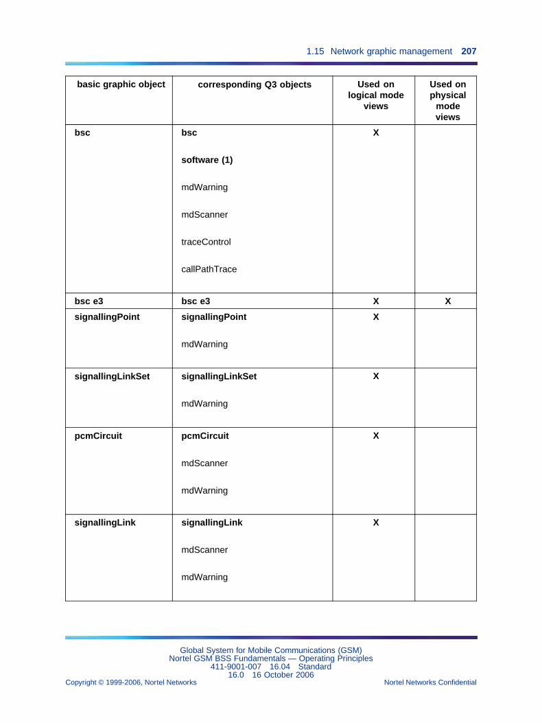
1.15 Network graphic management 207
basic graphic object corresponding Q3 objects Used onlogical mode
views
Used onphysical
modeviews
bsc bsc
software (1)
mdWarning
mdScanner
traceControl
callPathTrace
X
bsc e3 bsc e3 X X
signallingPoint signallingPoint
mdWarning
X
signallingLinkSet signallingLinkSet
mdWarning
X
pcmCircuit pcmCircuit
mdScanner
mdWarning
X
signallingLink signallingLink
mdScanner
mdWarning
X
Global System for Mobile Communications (GSM)Nortel GSM BSS Fundamentals — Operating Principles
411-9001-007 16.04 Standard16.0 16 October 2006
Copyright © 1999-2006, Nortel Networks Nortel Networks Confidential
.
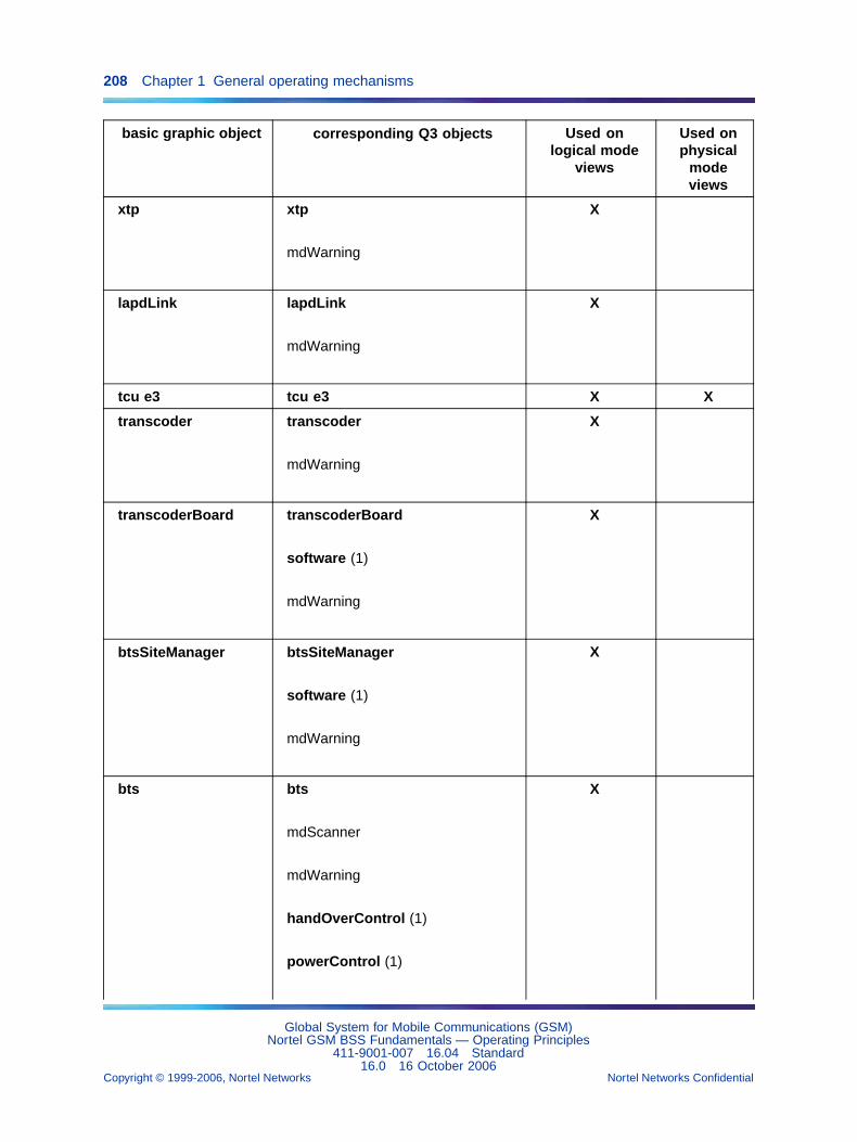
208 Chapter 1 General operating mechanisms
basic graphic object corresponding Q3 objects Used onlogical mode
views
Used onphysical
modeviews
xtp xtp
mdWarning
X
lapdLink lapdLink
mdWarning
X
tcu e3 tcu e3 X X
transcoder transcoder
mdWarning
X
transcoderBoard transcoderBoard
software (1)
mdWarning
X
btsSiteManager btsSiteManager
software (1)
mdWarning
X
bts bts
mdScanner
mdWarning
handOverControl (1)
powerControl (1)
X
Global System for Mobile Communications (GSM)Nortel GSM BSS Fundamentals — Operating Principles
411-9001-007 16.04 Standard16.0 16 October 2006
Copyright © 1999-2006, Nortel Networks Nortel Networks Confidential
.
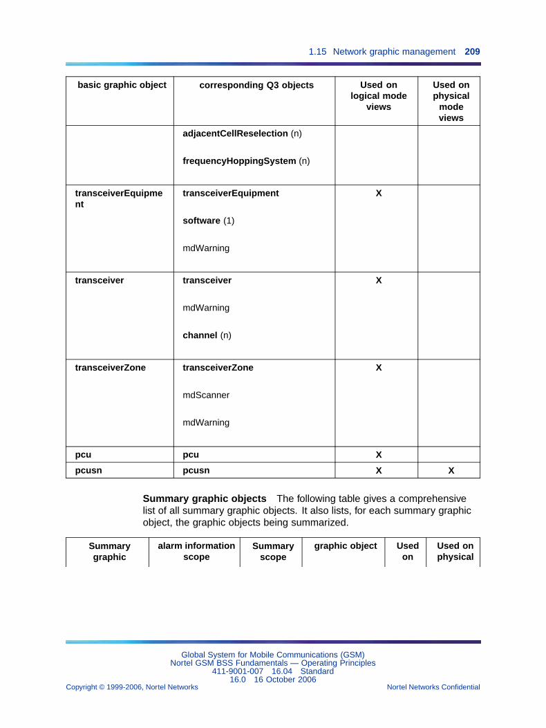
1.15 Network graphic management 209
basic graphic object corresponding Q3 objects Used onlogical mode
views
Used onphysical
modeviews
adjacentCellReselection (n)
frequencyHoppingSystem (n)
transceiverEquipment
transceiverEquipment
software (1)
mdWarning
X
transceiver transceiver
mdWarning
channel (n)
X
transceiverZone transceiverZone
mdScanner
mdWarning
X
pcu pcu X
pcusn pcusn X X
Summary graphic objects The following table gives a comprehensivelist of all summary graphic objects. It also lists, for each summary graphicobject, the graphic objects being summarized.
Summarygraphic
alarm informationscope
Summaryscope
graphic object Usedon
Used onphysical
Global System for Mobile Communications (GSM)Nortel GSM BSS Fundamentals — Operating Principles
411-9001-007 16.04 Standard16.0 16 October 2006
Copyright © 1999-2006, Nortel Networks Nortel Networks Confidential
.
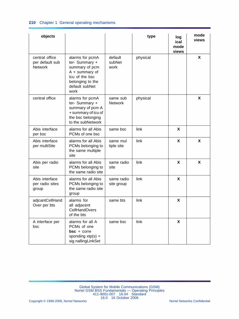
210 Chapter 1 General operating mechanisms
objects type logical
modeviews
modeviews
central officeper default subNetwork
alarms for pcmAter- Summary +summary of pcmA + summary oftcu of the bscbelonging to thedefault subNetwork
defaultsubNetwork
physical X
central office alarms for pcmAter- Summary +summary of pcm A+ summary of tcu ofthe bsc belongingto the subNetwork
same subNetwork
physical X
Abis interfaceper bsc
alarms for all AbisPCMs of one bsc
same bsc link X
Abis interfaceper multiSite
alarms for all AbisPCMs belonging tothe same multiplesite
same multiple site
link X X
Abis per radiosite
alarms for all AbisPCMs belonging tothe same radio site
same radiosite
link X X
Abis interfaceper radio sitesgroup
alarms for all AbisPCMs belonging tothe same radio sitegroup
same radiosite group
link X
adjcantCellHandOver per bts
alarms forall adjacentCellHandOversof the bts
same bts link X
A interface perbsc
alarms for all APCMs of onebsc + corresponding xtp(s) +sig nallingLinkSet
same bsc link X
Global System for Mobile Communications (GSM)Nortel GSM BSS Fundamentals — Operating Principles
411-9001-007 16.04 Standard16.0 16 October 2006
Copyright © 1999-2006, Nortel Networks Nortel Networks Confidential
.
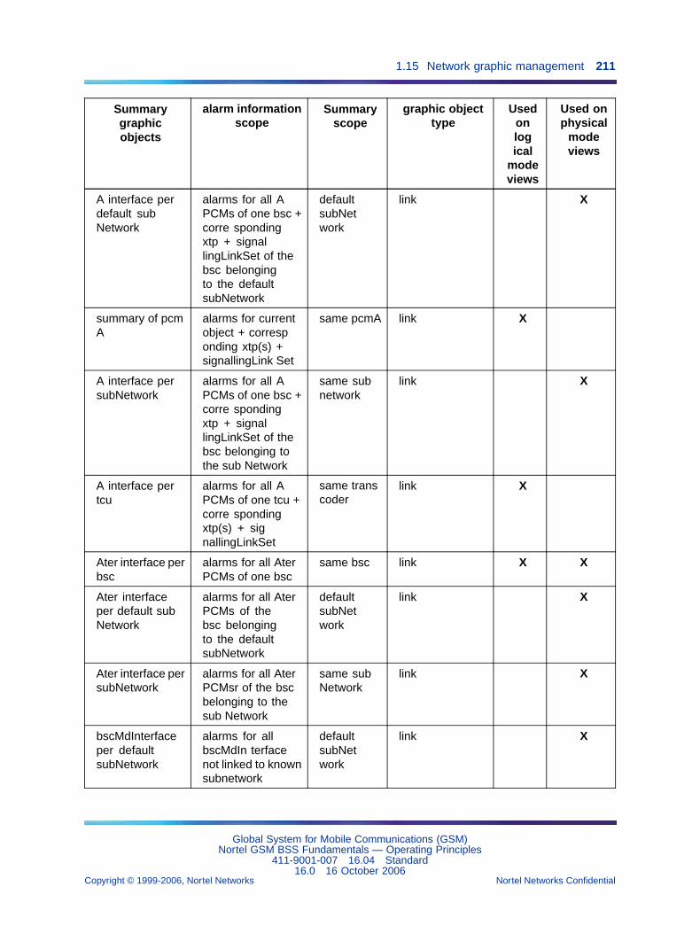
1.15 Network graphic management 211
Summarygraphicobjects
alarm informationscope
Summaryscope
graphic objecttype
Usedonlogical
modeviews
Used onphysical
modeviews
A interface perdefault subNetwork
alarms for all APCMs of one bsc +corre spondingxtp + signallingLinkSet of thebsc belongingto the defaultsubNetwork
defaultsubNetwork
link X
summary of pcmA
alarms for currentobject + corresponding xtp(s) +signallingLink Set
same pcmA link X
A interface persubNetwork
alarms for all APCMs of one bsc +corre spondingxtp + signallingLinkSet of thebsc belonging tothe sub Network
same subnetwork
link X
A interface pertcu
alarms for all APCMs of one tcu +corre spondingxtp(s) + signallingLinkSet
same transcoder
link X
Ater interface perbsc
alarms for all AterPCMs of one bsc
same bsc link X X
Ater interfaceper default subNetwork
alarms for all AterPCMs of thebsc belongingto the defaultsubNetwork
defaultsubNetwork
link X
Ater interface persubNetwork
alarms for all AterPCMsr of the bscbelonging to thesub Network
same subNetwork
link X
bscMdInterfaceper defaultsubNetwork
alarms for allbscMdIn terfacenot linked to knownsubnetwork
defaultsubNetwork
link X
Global System for Mobile Communications (GSM)Nortel GSM BSS Fundamentals — Operating Principles
411-9001-007 16.04 Standard16.0 16 October 2006
Copyright © 1999-2006, Nortel Networks Nortel Networks Confidential
.
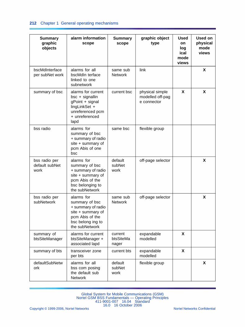
212 Chapter 1 General operating mechanisms
Summarygraphicobjects
alarm informationscope
Summaryscope
graphic objecttype
Usedonlogical
modeviews
Used onphysical
modeviews
bscMdInterfaceper subNet work
alarms for allbscMdIn terfacelinked to onesubnetwork
same subNetwork
link X
summary of bsc alarms for currentbsc + signallingPoint + signallingLinkSet +unreferenced pcm+ unreferencedlapd
current bsc physical simplemodelled off-page connector
X X
bss radio alarms forsummary of bsc+ summary of radiosite + summary ofpcm Abis of onebsc
same bsc flexible group
bss radio perdefault subNetwork
alarms forsummary of bsc+ summary of radiosite + summary ofpcm Abis of thebsc belonging tothe subNetwork
defaultsubNetwork
off-page selector X
bss radio persubNetwork
alarms forsummary of bsc+ summary of radiosite + summary ofpcm Abis of thebsc belong ing tothe subNetwork
same subNetwork
off-page selector X
summary ofbtsSiteManager
alarms for currentbtsSiteManager +associated lapd
currentbtsSiteManager
expandablemodelled
X
summary of bts transceiver zoneper bts
current bts expandablemodelled
X
defaultSubNetwork
alarms for allbss com posingthe default subNetwork
defaultsubNetwork
flexible group X
Global System for Mobile Communications (GSM)Nortel GSM BSS Fundamentals — Operating Principles
411-9001-007 16.04 Standard16.0 16 October 2006
Copyright © 1999-2006, Nortel Networks Nortel Networks Confidential
.
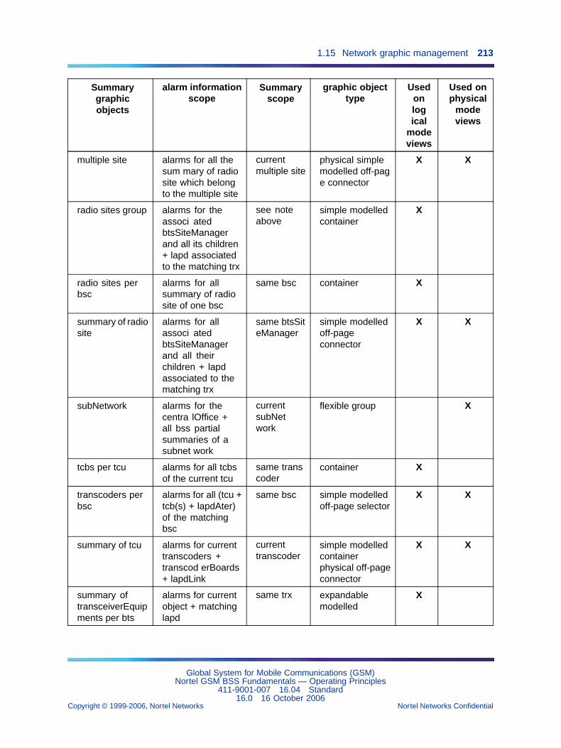
1.15 Network graphic management 213
Summarygraphicobjects
alarm informationscope
Summaryscope
graphic objecttype
Usedonlogical
modeviews
Used onphysical
modeviews
multiple site alarms for all thesum mary of radiosite which belongto the multiple site
currentmultiple site
physical simplemodelled off-page connector
X X
radio sites group alarms for theassoci atedbtsSiteManagerand all its children+ lapd associatedto the matching trx
see noteabove
simple modelledcontainer
X
radio sites perbsc
alarms for allsummary of radiosite of one bsc
same bsc container X
summary of radiosite
alarms for allassoci atedbtsSiteManagerand all theirchildren + lapdassociated to thematching trx
same btsSiteManager
simple modelledoff-pageconnector
X X
subNetwork alarms for thecentra lOffice +all bss partialsummaries of asubnet work
currentsubNetwork
flexible group X
tcbs per tcu alarms for all tcbsof the current tcu
same transcoder
container X
transcoders perbsc
alarms for all (tcu +tcb(s) + lapdAter)of the matchingbsc
same bsc simple modelledoff-page selector
X X
summary of tcu alarms for currenttranscoders +transcod erBoards+ lapdLink
currenttranscoder
simple modelledcontainerphysical off-pageconnector
X X
summary oftransceiverEquipments per bts
alarms for currentobject + matchinglapd
same trx expandablemodelled
X
Global System for Mobile Communications (GSM)Nortel GSM BSS Fundamentals — Operating Principles
411-9001-007 16.04 Standard16.0 16 October 2006
Copyright © 1999-2006, Nortel Networks Nortel Networks Confidential
.
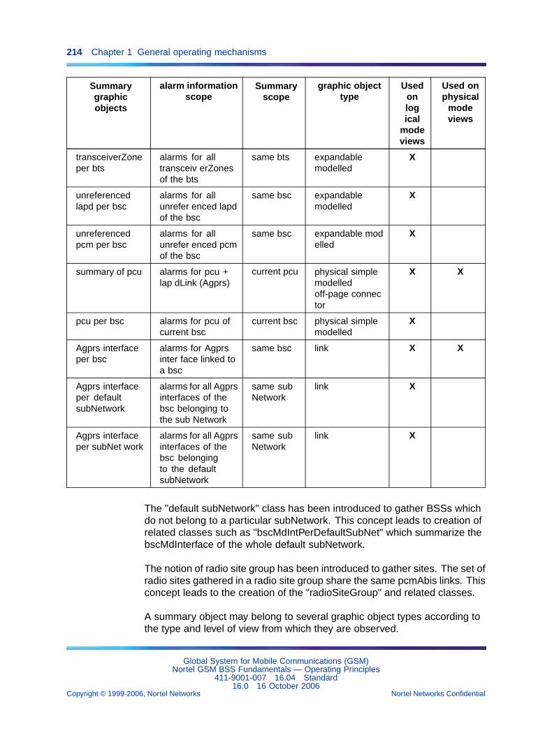
214 Chapter 1 General operating mechanisms
Summarygraphicobjects
alarm informationscope
Summaryscope
graphic objecttype
Usedonlogical
modeviews
Used onphysical
modeviews
transceiverZoneper bts
alarms for alltransceiv erZonesof the bts
same bts expandablemodelled
X
unreferencedlapd per bsc
alarms for allunrefer enced lapdof the bsc
same bsc expandablemodelled
X
unreferencedpcm per bsc
alarms for allunrefer enced pcmof the bsc
same bsc expandable modelled
X
summary of pcu alarms for pcu +lap dLink (Agprs)
current pcu physical simplemodelledoff-page connector
X X
pcu per bsc alarms for pcu ofcurrent bsc
current bsc physical simplemodelled
X
Agprs interfaceper bsc
alarms for Agprsinter face linked toa bsc
same bsc link X X
Agprs interfaceper defaultsubNetwork
alarms for all Agprsinterfaces of thebsc belonging tothe sub Network
same subNetwork
link X
Agprs interfaceper subNet work
alarms for all Agprsinterfaces of thebsc belongingto the defaultsubNetwork
same subNetwork
link X
The "default subNetwork" class has been introduced to gather BSSs whichdo not belong to a particular subNetwork. This concept leads to creation ofrelated classes such as "bscMdIntPerDefaultSubNet" which summarize thebscMdInterface of the whole default subNetwork.
The notion of radio site group has been introduced to gather sites. The set ofradio sites gathered in a radio site group share the same pcmAbis links. Thisconcept leads to the creation of the "radioSiteGroup" and related classes.
A summary object may belong to several graphic object types according tothe type and level of view from which they are observed.
Global System for Mobile Communications (GSM)Nortel GSM BSS Fundamentals — Operating Principles
411-9001-007 16.04 Standard16.0 16 October 2006
Copyright © 1999-2006, Nortel Networks Nortel Networks Confidential
.
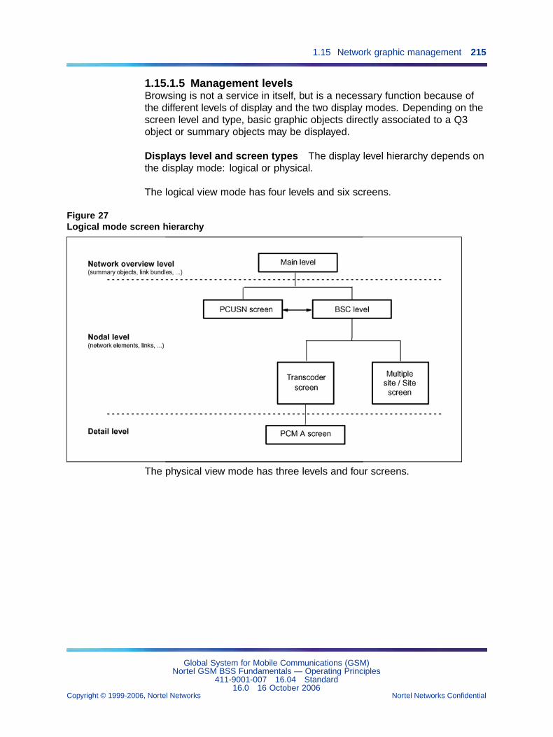
1.15 Network graphic management 215
1.15.1.5 Management levelsBrowsing is not a service in itself, but is a necessary function because ofthe different levels of display and the two display modes. Depending on thescreen level and type, basic graphic objects directly associated to a Q3object or summary objects may be displayed.
Displays level and screen types The display level hierarchy depends onthe display mode: logical or physical.
The logical view mode has four levels and six screens.
Figure 27Logical mode screen hierarchy
The physical view mode has three levels and four screens.
Global System for Mobile Communications (GSM)Nortel GSM BSS Fundamentals — Operating Principles
411-9001-007 16.04 Standard16.0 16 October 2006
Copyright © 1999-2006, Nortel Networks Nortel Networks Confidential
.
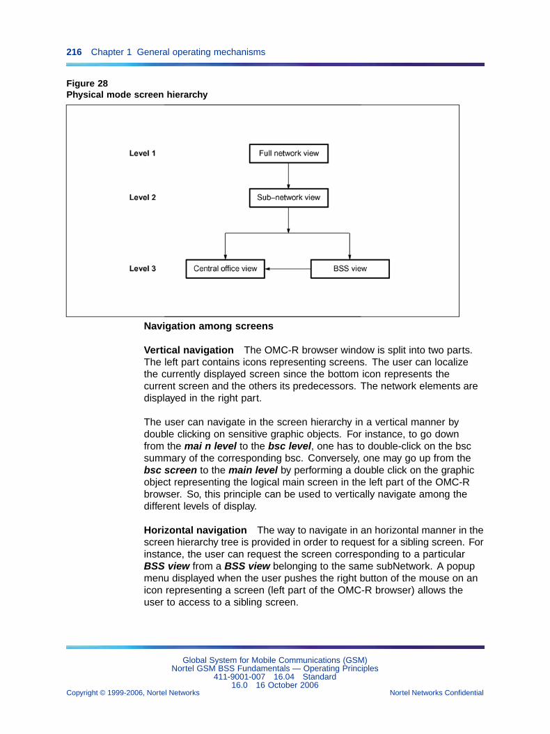
216 Chapter 1 General operating mechanisms
Figure 28Physical mode screen hierarchy
Navigation among screens
Vertical navigation The OMC-R browser window is split into two parts.The left part contains icons representing screens. The user can localizethe currently displayed screen since the bottom icon represents thecurrent screen and the others its predecessors. The network elements aredisplayed in the right part.
The user can navigate in the screen hierarchy in a vertical manner bydouble clicking on sensitive graphic objects. For instance, to go downfrom the mai n level to the bsc level, one has to double-click on the bscsummary of the corresponding bsc. Conversely, one may go up from thebsc screen to the main level by performing a double click on the graphicobject representing the logical main screen in the left part of the OMC-Rbrowser. So, this principle can be used to vertically navigate among thedifferent levels of display.
Horizontal navigation The way to navigate in an horizontal manner in thescreen hierarchy tree is provided in order to request for a sibling screen. Forinstance, the user can request the screen corresponding to a particularBSS view from a BSS view belonging to the same subNetwork. A popupmenu displayed when the user pushes the right button of the mouse on anicon representing a screen (left part of the OMC-R browser) allows theuser to access to a sibling screen.
Global System for Mobile Communications (GSM)Nortel GSM BSS Fundamentals — Operating Principles
411-9001-007 16.04 Standard16.0 16 October 2006
Copyright © 1999-2006, Nortel Networks Nortel Networks Confidential
.
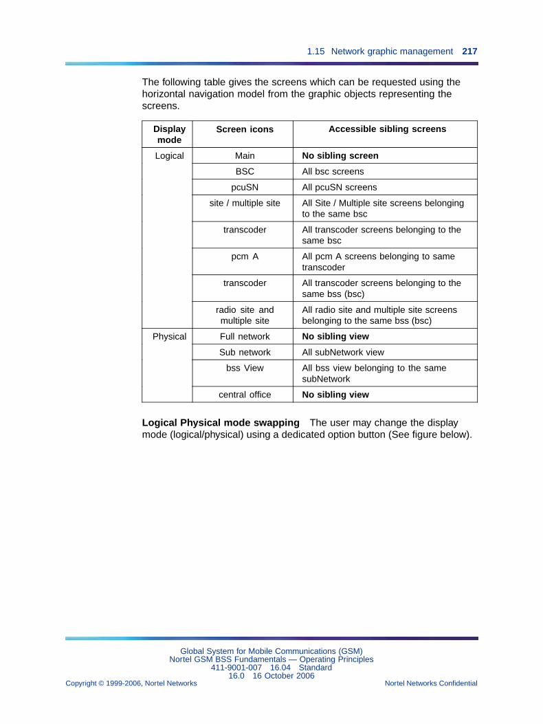
1.15 Network graphic management 217
The following table gives the screens which can be requested using thehorizontal navigation model from the graphic objects representing thescreens.
Displaymode
Screen icons Accessible sibling screens
Main No sibling screen
BSC All bsc screens
pcuSN All pcuSN screens
site / multiple site All Site / Multiple site screens belongingto the same bsc
transcoder All transcoder screens belonging to thesame bsc
pcm A All pcm A screens belonging to sametranscoder
transcoder All transcoder screens belonging to thesame bss (bsc)
Logical
radio site andmultiple site
All radio site and multiple site screensbelonging to the same bss (bsc)
Full network No sibling view
Sub network All subNetwork view
bss View All bss view belonging to the samesubNetwork
Physical
central office No sibling view
Logical Physical mode swapping The user may change the displaymode (logical/physical) using a dedicated option button (See figure below).
Global System for Mobile Communications (GSM)Nortel GSM BSS Fundamentals — Operating Principles
411-9001-007 16.04 Standard16.0 16 October 2006
Copyright © 1999-2006, Nortel Networks Nortel Networks Confidential
.
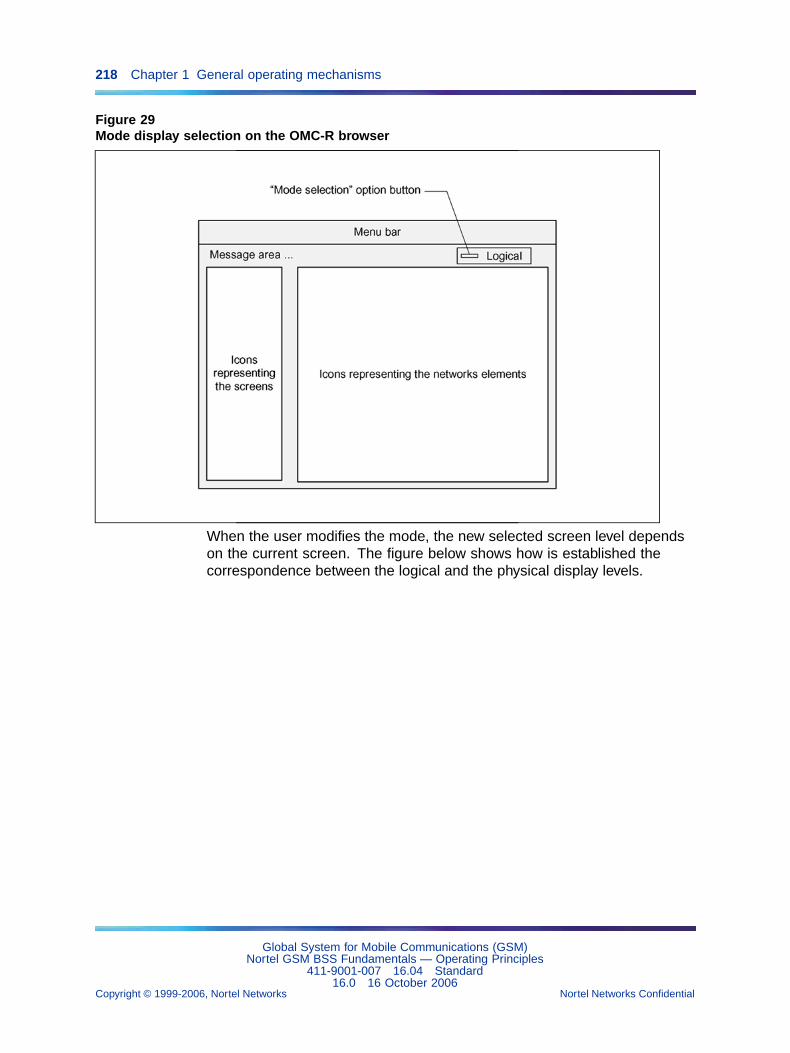
218 Chapter 1 General operating mechanisms
Figure 29Mode display selection on the OMC-R browser
When the user modifies the mode, the new selected screen level dependson the current screen. The figure below shows how is established thecorrespondence between the logical and the physical display levels.
Global System for Mobile Communications (GSM)Nortel GSM BSS Fundamentals — Operating Principles
411-9001-007 16.04 Standard16.0 16 October 2006
Copyright © 1999-2006, Nortel Networks Nortel Networks Confidential
.
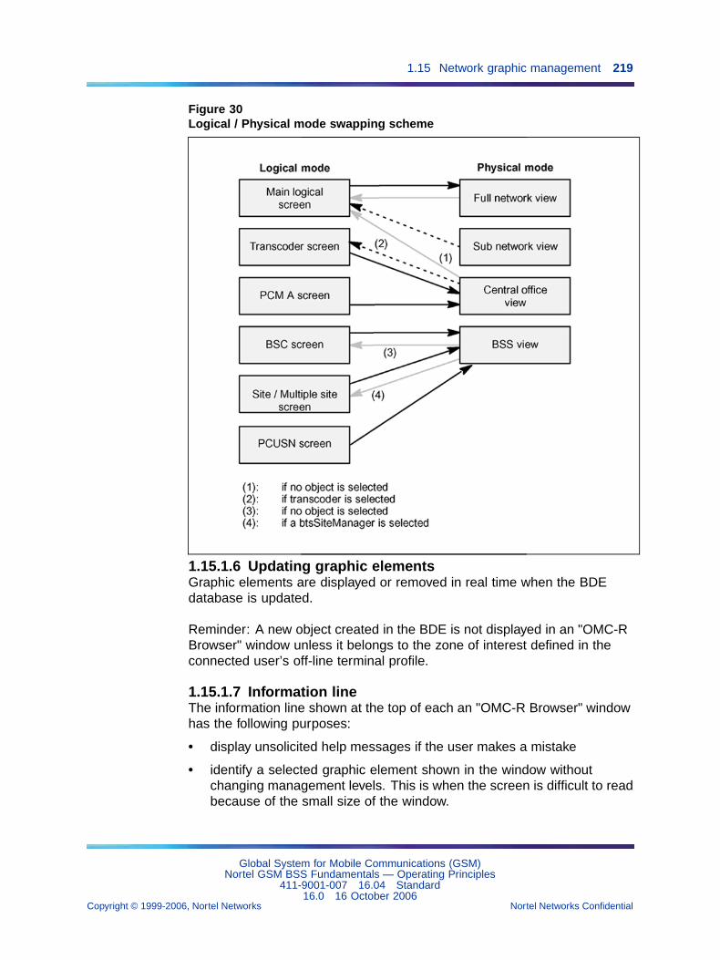
1.15 Network graphic management 219
Figure 30Logical / Physical mode swapping scheme
1.15.1.6 Updating graphic elementsGraphic elements are displayed or removed in real time when the BDEdatabase is updated.
Reminder: A new object created in the BDE is not displayed in an "OMC-RBrowser" window unless it belongs to the zone of interest defined in theconnected user’s off-line terminal profile.
1.15.1.7 Information lineThe information line shown at the top of each an "OMC-R Browser" windowhas the following purposes:
• display unsolicited help messages if the user makes a mistake
• identify a selected graphic element shown in the window withoutchanging management levels. This is when the screen is difficult to readbecause of the small size of the window.
Global System for Mobile Communications (GSM)Nortel GSM BSS Fundamentals — Operating Principles
411-9001-007 16.04 Standard16.0 16 October 2006
Copyright © 1999-2006, Nortel Networks Nortel Networks Confidential
.
220 Chapter 1 General operating mechanisms
Moreover, it allows the user to identify the radio sites using a given PCMAbis link on request.
The information displayed on the line gives the name and/or referencenumber of the objects described by the selected graphic elements.
1.15.1.8 On-line helpUsers can obtain on-line help at all times on all management levels.
• User help requests
Select the Color legend option of Help menu in an "OMC-R Browser"window. A text appears in the help window that opens on the screen toremind users of the meaning of the different colors shown in the window.
• Unsolicited system help
If the user makes a mistake, unsolicited system help messages appearon the information line.
1.15.1.9 Sizing the OMC-R browser windowsThey can be enlarged to fill the entire screen or reduced to small size.
No information is lost when the windows are reduced, but they becomemore difficult to read. The graphic elements are reorganized to be as legibleas possible and their size is tailored to match the size of the window.
1.15.1.10 OMC-R browser iconWhen an "OMC-R browser" window is iconified, it is represented by theOMC-R Browser icon on the terminal screen.
The pictogram is symbolic and does not represent alarm states on themanagement level that was on display when the window was closed
1.15.2 State managementObjects appearing in this view are graphic objects, which conform to theNortel Corporate Design Group (CDG) recommendation:
• The shape and the aspect of the object depends on the object type (link,managed Q3 object, summary ...).
• The state of the Q3 objects is displayed using specific symbols locatedon the left top.
• The alarms are displayed using colored alarm balloons and objectbackground.
• The selection status is shown using a white border. The objects can beselected using the mouse.
States are not displayed on the physical view.
Global System for Mobile Communications (GSM)Nortel GSM BSS Fundamentals — Operating Principles
411-9001-007 16.04 Standard16.0 16 October 2006
Copyright © 1999-2006, Nortel Networks Nortel Networks Confidential
.
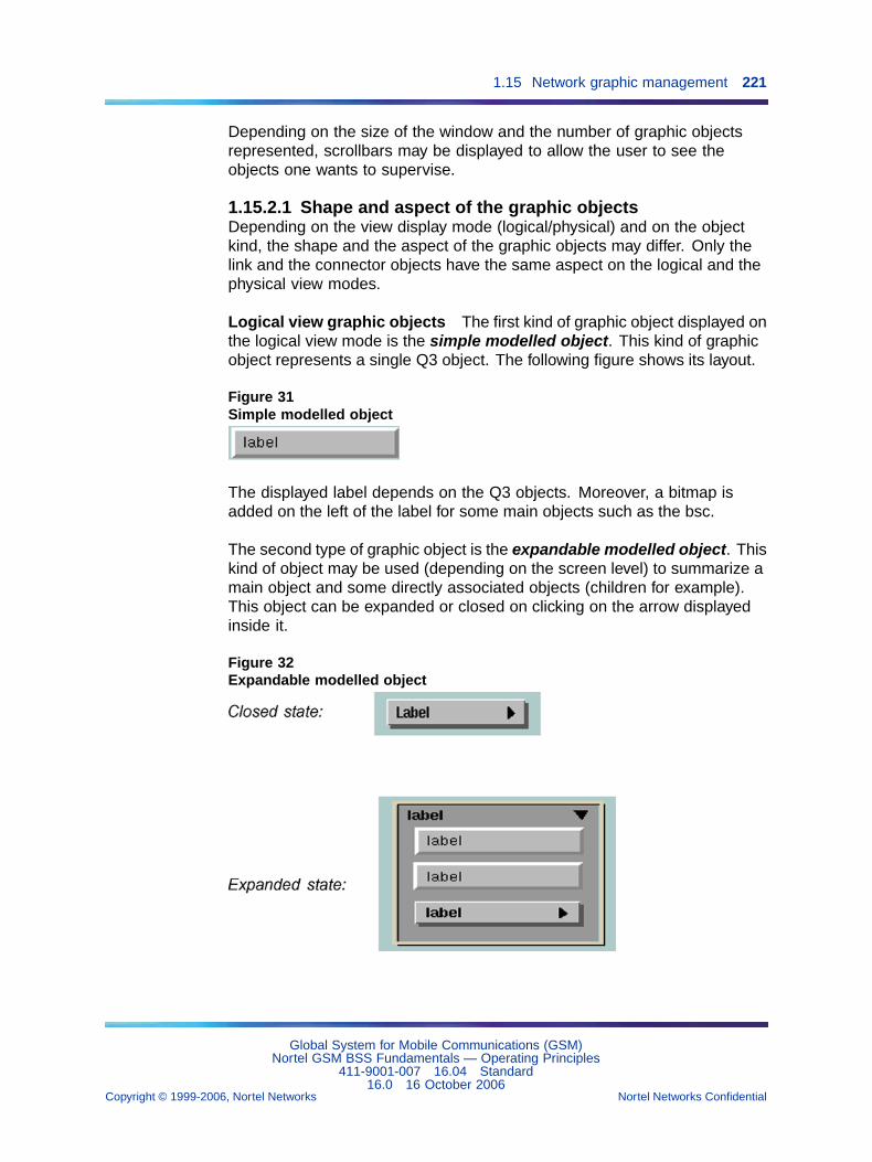
1.15 Network graphic management 221
Depending on the size of the window and the number of graphic objectsrepresented, scrollbars may be displayed to allow the user to see theobjects one wants to supervise.
1.15.2.1 Shape and aspect of the graphic objectsDepending on the view display mode (logical/physical) and on the objectkind, the shape and the aspect of the graphic objects may differ. Only thelink and the connector objects have the same aspect on the logical and thephysical view modes.
Logical view graphic objects The first kind of graphic object displayed onthe logical view mode is the simple modelled object. This kind of graphicobject represents a single Q3 object. The following figure shows its layout.
Figure 31Simple modelled object
The displayed label depends on the Q3 objects. Moreover, a bitmap isadded on the left of the label for some main objects such as the bsc.
The second type of graphic object is the expandable modelled object. Thiskind of object may be used (depending on the screen level) to summarize amain object and some directly associated objects (children for example).This object can be expanded or closed on clicking on the arrow displayedinside it.
Figure 32Expandable modelled object
Global System for Mobile Communications (GSM)Nortel GSM BSS Fundamentals — Operating Principles
411-9001-007 16.04 Standard16.0 16 October 2006
Copyright © 1999-2006, Nortel Networks Nortel Networks Confidential
.
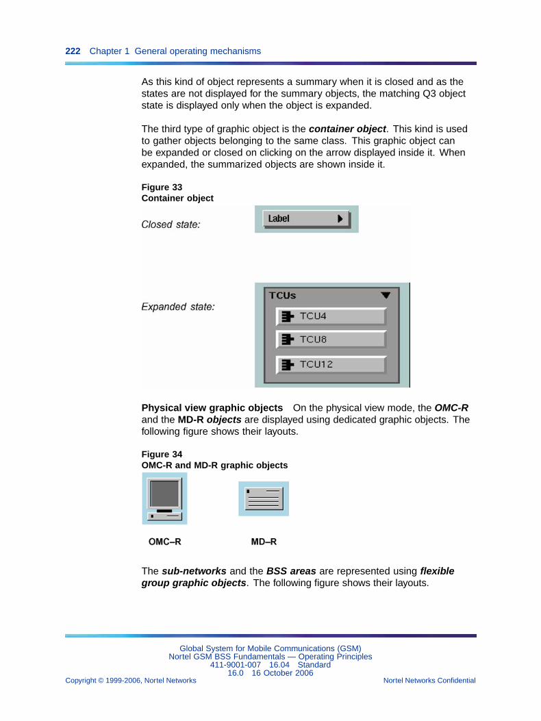
222 Chapter 1 General operating mechanisms
As this kind of object represents a summary when it is closed and as thestates are not displayed for the summary objects, the matching Q3 objectstate is displayed only when the object is expanded.
The third type of graphic object is the container object. This kind is usedto gather objects belonging to the same class. This graphic object canbe expanded or closed on clicking on the arrow displayed inside it. Whenexpanded, the summarized objects are shown inside it.
Figure 33Container object
Physical view graphic objects On the physical view mode, the OMC-Rand the MD-R objects are displayed using dedicated graphic objects. Thefollowing figure shows their layouts.
Figure 34OMC-R and MD-R graphic objects
The sub-networks and the BSS areas are represented using flexiblegroup graphic objects. The following figure shows their layouts.
Global System for Mobile Communications (GSM)Nortel GSM BSS Fundamentals — Operating Principles
411-9001-007 16.04 Standard16.0 16 October 2006
Copyright © 1999-2006, Nortel Networks Nortel Networks Confidential
.
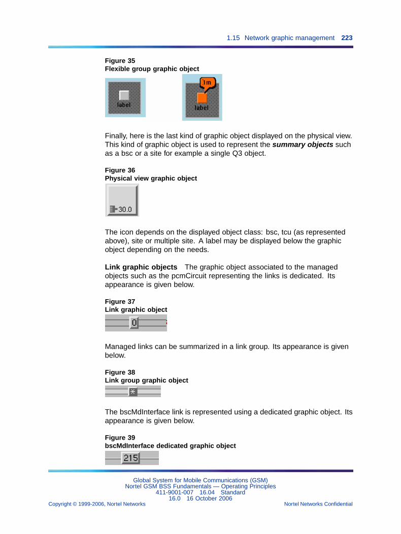
1.15 Network graphic management 223
Figure 35Flexible group graphic object
Finally, here is the last kind of graphic object displayed on the physical view.This kind of graphic object is used to represent the summary objects suchas a bsc or a site for example a single Q3 object.
Figure 36Physical view graphic object
The icon depends on the displayed object class: bsc, tcu (as representedabove), site or multiple site. A label may be displayed below the graphicobject depending on the needs.
Link graphic objects The graphic object associated to the managedobjects such as the pcmCircuit representing the links is dedicated. Itsappearance is given below.
Figure 37Link graphic object
Managed links can be summarized in a link group. Its appearance is givenbelow.
Figure 38Link group graphic object
The bscMdInterface link is represented using a dedicated graphic object. Itsappearance is given below.
Figure 39bscMdInterface dedicated graphic object
Global System for Mobile Communications (GSM)Nortel GSM BSS Fundamentals — Operating Principles
411-9001-007 16.04 Standard16.0 16 October 2006
Copyright © 1999-2006, Nortel Networks Nortel Networks Confidential
.
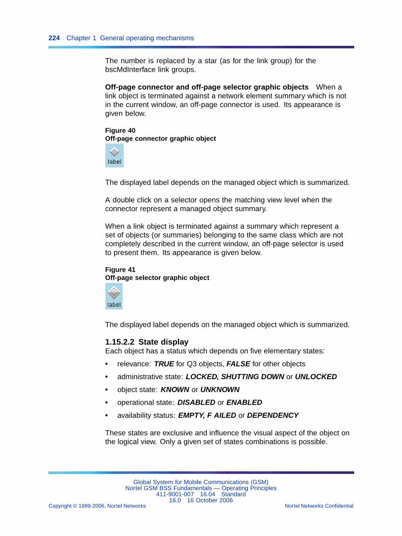
224 Chapter 1 General operating mechanisms
The number is replaced by a star (as for the link group) for thebscMdInterface link groups.
Off-page connector and off-page selector graphic objects When alink object is terminated against a network element summary which is notin the current window, an off-page connector is used. Its appearance isgiven below.
Figure 40Off-page connector graphic object
The displayed label depends on the managed object which is summarized.
A double click on a selector opens the matching view level when theconnector represent a managed object summary.
When a link object is terminated against a summary which represent aset of objects (or summaries) belonging to the same class which are notcompletely described in the current window, an off-page selector is usedto present them. Its appearance is given below.
Figure 41Off-page selector graphic object
The displayed label depends on the managed object which is summarized.
1.15.2.2 State displayEach object has a status which depends on five elementary states:
• relevance: TRUE for Q3 objects, FALSE for other objects
• administrative state: LOCKED, SHUTTING DOWN or UNLOCKED
• object state: KNOWN or UNKNOWN
• operational state: DISABLED or ENABLED
• availability status: EMPTY, F AILED or DEPENDENCY
These states are exclusive and influence the visual aspect of the object onthe logical view. Only a given set of states combinations is possible.
Global System for Mobile Communications (GSM)Nortel GSM BSS Fundamentals — Operating Principles
411-9001-007 16.04 Standard16.0 16 October 2006
Copyright © 1999-2006, Nortel Networks Nortel Networks Confidential
.
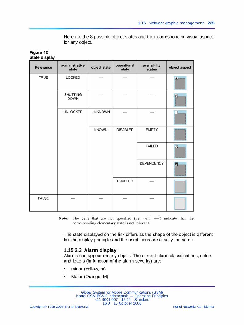
1.15 Network graphic management 225
Here are the 8 possible object states and their corresponding visual aspectfor any object.
Figure 42State display
The state displayed on the link differs as the shape of the object is differentbut the display principle and the used icons are exactly the same.
1.15.2.3 Alarm displayAlarms can appear on any object. The current alarm classifications, colorsand letters (in function of the alarm severity) are:
• minor (Yellow, m)
• Major (Orange, M)
Global System for Mobile Communications (GSM)Nortel GSM BSS Fundamentals — Operating Principles
411-9001-007 16.04 Standard16.0 16 October 2006
Copyright © 1999-2006, Nortel Networks Nortel Networks Confidential
.
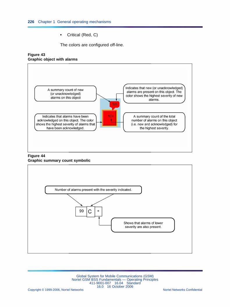
226 Chapter 1 General operating mechanisms
• Critical (Red, C)
The colors are configured off-line.
Figure 43Graphic object with alarms
Figure 44Graphic summary count symbolic
Global System for Mobile Communications (GSM)Nortel GSM BSS Fundamentals — Operating Principles
411-9001-007 16.04 Standard16.0 16 October 2006
Copyright © 1999-2006, Nortel Networks Nortel Networks Confidential
.
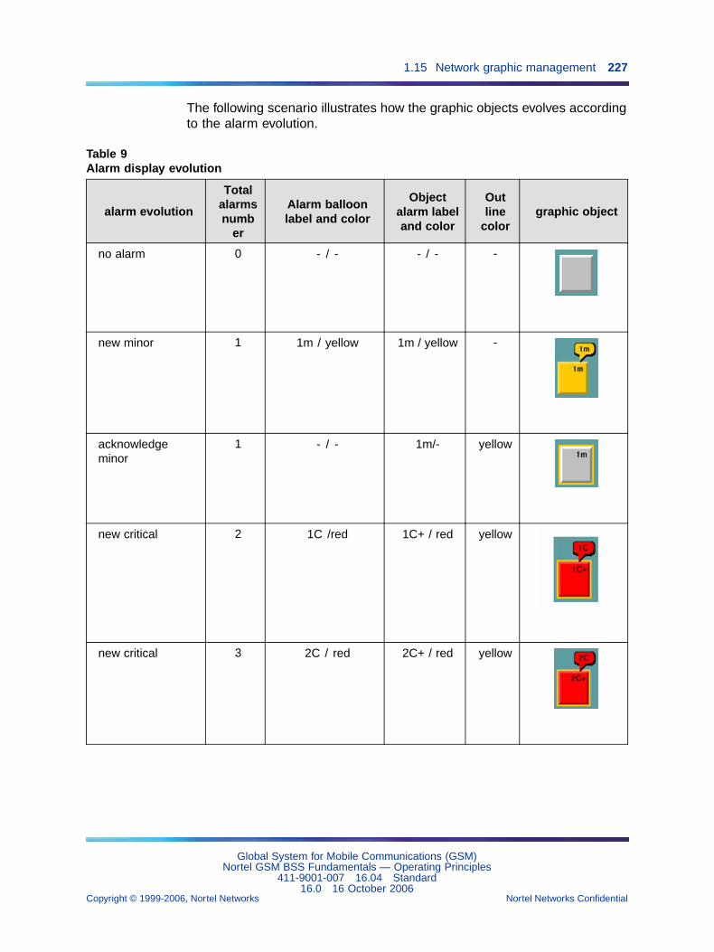
1.15 Network graphic management 227
The following scenario illustrates how the graphic objects evolves accordingto the alarm evolution.
Table 9Alarm display evolution
alarm evolution
Totalalarmsnumb
er
Alarm balloonlabel and color
Objectalarm labeland color
Outline
colorgraphic object
no alarm 0 - / - - / - -
new minor 1 1m / yellow 1m / yellow -
acknowledgeminor
1 - / - 1m/- yellow
new critical 2 1C /red 1C+ / red yellow
new critical 3 2C / red 2C+ / red yellow
Global System for Mobile Communications (GSM)Nortel GSM BSS Fundamentals — Operating Principles
411-9001-007 16.04 Standard16.0 16 October 2006
Copyright © 1999-2006, Nortel Networks Nortel Networks Confidential
.
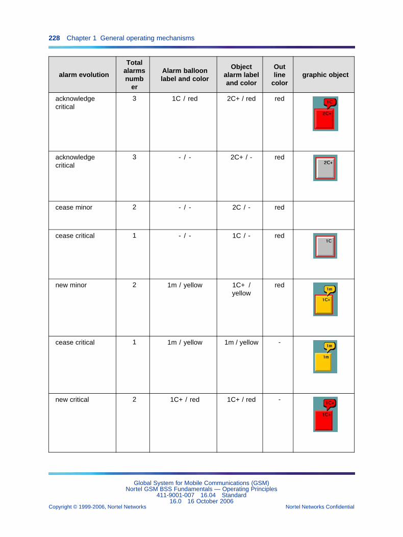
228 Chapter 1 General operating mechanisms
alarm evolution
Totalalarmsnumb
er
Alarm balloonlabel and color
Objectalarm labeland color
Outline
colorgraphic object
acknowledgecritical
3 1C / red 2C+ / red red
acknowledgecritical
3 - / - 2C+ / - red
cease minor 2 - / - 2C / - red
cease critical 1 - / - 1C / - red
new minor 2 1m / yellow 1C+ /yellow
red
cease critical 1 1m / yellow 1m / yellow -
new critical 2 1C+ / red 1C+ / red -
Global System for Mobile Communications (GSM)Nortel GSM BSS Fundamentals — Operating Principles
411-9001-007 16.04 Standard16.0 16 October 2006
Copyright © 1999-2006, Nortel Networks Nortel Networks Confidential
.
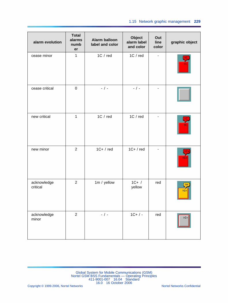
1.15 Network graphic management 229
alarm evolution
Totalalarmsnumb
er
Alarm balloonlabel and color
Objectalarm labeland color
Outline
colorgraphic object
cease minor 1 1C / red 1C / red -
cease critical 0 - / - - / - -
new critical 1 1C / red 1C / red -
new minor 2 1C+ / red 1C+ / red -
acknowledgecritical
2 1m / yellow 1C+ /yellow
red
acknowledgeminor
2 - / - 1C+ / - red
Global System for Mobile Communications (GSM)Nortel GSM BSS Fundamentals — Operating Principles
411-9001-007 16.04 Standard16.0 16 October 2006
Copyright © 1999-2006, Nortel Networks Nortel Networks Confidential
.
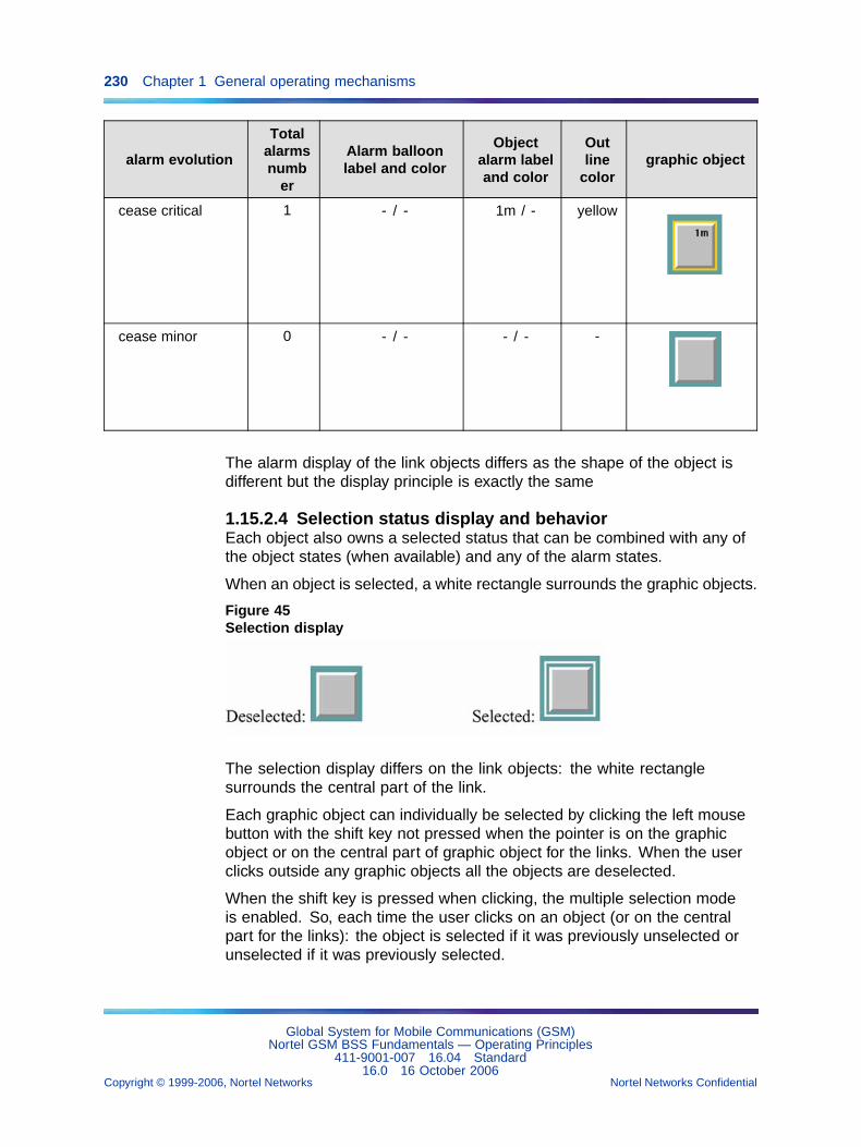
230 Chapter 1 General operating mechanisms
alarm evolution
Totalalarmsnumb
er
Alarm balloonlabel and color
Objectalarm labeland color
Outline
colorgraphic object
cease critical 1 - / - 1m / - yellow
cease minor 0 - / - - / - -
The alarm display of the link objects differs as the shape of the object isdifferent but the display principle is exactly the same
1.15.2.4 Selection status display and behaviorEach object also owns a selected status that can be combined with any ofthe object states (when available) and any of the alarm states.
When an object is selected, a white rectangle surrounds the graphic objects.
Figure 45Selection display
The selection display differs on the link objects: the white rectanglesurrounds the central part of the link.
Each graphic object can individually be selected by clicking the left mousebutton with the shift key not pressed when the pointer is on the graphicobject or on the central part of graphic object for the links. When the userclicks outside any graphic objects all the objects are deselected.
When the shift key is pressed when clicking, the multiple selection modeis enabled. So, each time the user clicks on an object (or on the centralpart for the links): the object is selected if it was previously unselected orunselected if it was previously selected.
Global System for Mobile Communications (GSM)Nortel GSM BSS Fundamentals — Operating Principles
411-9001-007 16.04 Standard16.0 16 October 2006
Copyright © 1999-2006, Nortel Networks Nortel Networks Confidential
.
1.16 Security management 231
Some configuration and functional Q3 objects such as the software or theadjacentCellHandOvers are not displayed into the browser. They are named"hidden objects". They are automatically selected when the matching"reference" Q3 object is selected. These "reference" objects are named"hiding" objects. For example, when the user selects a bsc, the matchingbsc software is automatically selected when it exists. But, the selection ofthe hidden object is made as a snapshot and not refreshed in real time. Thatis to say the hidden objects remain in the selected object list until the hidingobject is reselected even if they are deleted. The same kind of behaviorexists on hidden object creation: it is not automatically selected when thematching hiding object is already selected. In this case the user have toreselect the hiding object to be able to access to the new hidden object.
When a Q3 "reference" object is selected, the user has access to allcommands that are relevant to both the object itself (hiding object) and allassociated configuration and functional objects (hidden objects).
For instance, if the graphic object representing a bts is selected, the userwill have access to all commands relevant to:
• the bts object instance (main configuration object)
• the handOverControl object instance
• the powerControl object instance
• the adjacentCellReselection object instance(s)
• the frequencyHoppingSystem object instance(s)
• the mdScanner object instance(s)
• the mdWarning object instance(s)
1.16 Security management1.16.1 Overview
Security management controls users’ access to OMC-R services.
The OMC-R manager Security Management function does the following:
• monitors service access by controlling the information that users canaccess and controlling the terminals through which users communicatewith the OMC-R
It is based on the analysis of user and terminal profiles that defineaccess rights to different services.
• monitors work sessions by controlling each step in the routine (login,session interactions, logout)
It is based on the following:
— analysis of users’ profiles defining each user’s working conditions
Global System for Mobile Communications (GSM)Nortel GSM BSS Fundamentals — Operating Principles
411-9001-007 16.04 Standard16.0 16 October 2006
Copyright © 1999-2006, Nortel Networks Nortel Networks Confidential
.
232 Chapter 1 General operating mechanisms
— recording user interactions with the system: command executionand system responses to the commands, system warning messages
It uses the system and user session logs as supports.
User and terminal profiles are stored in mirrored files on the OMC-Rmanagerdisks.
1.16.2 Service access management1.16.2.1 Access rightsThere are three categories of service access rights, as follows:
• command domain
• output domain
• zone of interest
Command domain The user’s rights to execute commands are definedby a command domain that contains the list of command classes that auser is allowed to access. A command domain contains up to twenty-fivecommand classes.
A command class is identified by a number in static configuration data thatreferences a set of commands associated with a given object (a CreatebtsSiteManager object command may be allowed in a user’s profile buta Create mdScanner object command not allowed). One command maybelong to several classes.
The user’s command domain defines the set of data that the user canaccess through MMI commands. Managing the alarms generated by theFault Management function is, for instance, controlled by a command class.
The mobile network operator, in agreement with the manufacturer, definescommand classes. The command classes are unique to an installationand are configured before the network is commissioned. They cannot bemodified in user work sessions.
The MMI List command classes command allows authorized users tolist all the MMI commands and command class(es).
Output domain The user or terminal rights to output data are defined inthe output domain that contains the authorized output classes.
Output classes provide access to various MMI windows from the main MMIscreen. Each window allows the user to manage (during work sessions) ormonitor (from off-line terminals) a set of same-kind data. BSS instrumentpanel observation data are, for instance, in this category.
Global System for Mobile Communications (GSM)Nortel GSM BSS Fundamentals — Operating Principles
411-9001-007 16.04 Standard16.0 16 October 2006
Copyright © 1999-2006, Nortel Networks Nortel Networks Confidential
.
1.16 Security management 233
The mobile network operator, in agreement with the manufacturer, definesoutput classes in the static configuration. They cannot be modified. Outputclasses are described at the end of this chapter.
The command domain and output domain defined in the same user’s profilemust be consistent.
Zone of interest The zone of interest defines the user’s field of actionduring a work session. It defines the portion of the network monitored by aterminal when the user has not opened a work session on the terminal.
The zone of interest is divided into the BSS zone and the OMC zone.
• BSS zone of interest
The BSS zone of interest allocated to a user defines the BSSs for whichthe user is responsible (one BSS may be managed by different users)and allows the user to do the following:
— filter the commands entered on the Man-Machine interface accordingto the objects involved
— filter the data that can be managed according to the source
A terminal BSS zone of interest defines the BSSs that users can monitoroutside work sessions and allows users to filter the data that they canconsult from the terminal according to the source.
• OMC zone of interest
The OMC zone of interest allocated to a user or terminal defines accessrights to the notifications and alarm messages generated in response tounsolicited messages by the OMC-R manager or agent.
1.16.2.2 User profilesA user is registered as an OMC-R user by the definition of a specific profile.The network operator creates and determines user profiles.
A user’s profile contains the following information:
• name and password
• password validity duration
• access rights (command domain, output domain, zone of interest)
• authorized inactivity time
• authorized access time
• session context saving mode
Global System for Mobile Communications (GSM)Nortel GSM BSS Fundamentals — Operating Principles
411-9001-007 16.04 Standard16.0 16 October 2006
Copyright © 1999-2006, Nortel Networks Nortel Networks Confidential
.
234 Chapter 1 General operating mechanisms
The operator controls the profiles of all the system users. They can onlybe modified and deleted by authorized users. The profiles can be modifiedinside or outside work sessions. The new parameters are used the nexttime the concerned user opens a work session.
When a user profile is deleted, the user is denied access to the network.The session is not aborted if the user is working when the profile is deleted,but future login requests are denied.
Name and password To access the network, a user must be known to thesystem. A user is identified by a specific name and password.
Name and password are a unique combination that identifies the user atlogin time. They are compared to the values defined in the user’s profile andallow the OMC-R to control user access, as follows:
• The name is limited to thirty characters.
The name of an OMC-R user cannot be modified
• The password must begin with a letter and be at least six-characterslong, with one non-alphanumeric character among the first eightcharacters.
A list of "forbidden" passwords is defined in static configuration data.Any password beginning with a string of characters that matches one ofthe passwords in the list is refused (the character case is significant).
The password of an OMC-R user can be modified in a work session bythe user (MMI Change password command) or by an authorized user(MMI Set a user profile command).
When a user runs the Change password command, current and newpasswords are not displayed on the terminal screen. The new passwordmust be entered twice to be validated.
A new password must be different from its N previous occurrences (Nis defined in static configuration data) and is only used the next timethe user logs into a work session.
Password validity duration For security reasons, users’ passwords mustbe changed at regular intervals.
The password validity duration is limited and can be modified. Users receivea warning message just before the validity counter defined in their profileexpires.
If a password is not updated at the required time, the user must change it onopening the next work session. The system displays the password entrywindow at the start of the session. If the user does not update the password,the system refuses access to commands on the Man-Machine interface.
Global System for Mobile Communications (GSM)Nortel GSM BSS Fundamentals — Operating Principles
411-9001-007 16.04 Standard16.0 16 October 2006
Copyright © 1999-2006, Nortel Networks Nortel Networks Confidential
.
1.16 Security management 235
Access rights There are three categories of user access rights to OMC-Rservices, which are the following:
• The command domain defines the commands that the user is allowed toexecute in work sessions and the data that can be accessed throughMMI commands.
• The output domain defines the sets of data that the user can managefrom dedicated windows.
• The zone of interest defines the network entities where the user isallowed to intervene:
— Configuration commands are only allowed on the objects describingentities in the zone of interest.
— Notifications and alarm messages are only displayed if thecorresponding unsolicited messages are generated by entitiesdefined in the zone of interest.
The results of multiple-type (scope & filter) commands are not filtered bythe zone of interest.
Inactivity time-out During a work session, a counter defines themaximum period of user inactivity between two commands. After that time,the system automatically generates a logout request.
• The default inactivity time is five minutes. It can be set to another valueat a later time and may be infinite.
• A warning message is displayed on the terminal just before this periodelapses. The session is broken off with no further warning when thetime runs out.
• The inactivity counter is reset to zero by moving the mouse in an MMIwindow displayed on the terminal screen, without the user actuallyentering a command.
The jobs executed by the Job scheduler are not counted in inactivitytime-out.
Access time A table defines the time at which users are allowed to logineach day and the time after which access is prohibited.
If the user is still working after the authorized access time, a warningmessage is periodically displayed on the terminal and a buzzer is triggered,but the system does not close the session.
Authorized users define and update the table. A user is not allowed toaccess the OMC-R outside the defined time band. The time band mayinclude midnight (for example: 20H - 4H).
Global System for Mobile Communications (GSM)Nortel GSM BSS Fundamentals — Operating Principles
411-9001-007 16.04 Standard16.0 16 October 2006
Copyright © 1999-2006, Nortel Networks Nortel Networks Confidential
.
236 Chapter 1 General operating mechanisms
Session context saving mode This parameter indicates whether theMan-Machine interface configuration is saved automatically each time theconcerned user logs out or only on request.
The automatic context saving allows to start a new work session withthe MMI characteristics of the last work session: All windows opened oriconified on the terminal screen are represented in the same way and at thesame place. Specific display options are saved too.
However, one should note that, in order to avoid confusion, the windowinformation contents correspond to the state of the network at the time thenew session is open.
If the session context is not saved, the standard MMI screen is displayedwhen a newwork session is started.
User profile management commands OMC-R user profiles aredescribed as user profile objects on the Man-Machine interface.
The following object-oriented commands are managed locally by theOMC-R manager:
• Create / Set / Display / Delete
These commands are used to manage system user profiles.
Modified values are used at the start of the next work session.
• Change password
This command allows users to change their password during a worksession using the password entry window on the terminal screen.
The new password must be used the next time the user logs in.
• Modify session context saving mode
This command allows users to set their own MMI context on opening awork session (see the previous page).
By default, the automatic saving mode is on when the user profile iscreated or modified by the network operator. Then, the concerned usercan de-activate or re-activate it by this command.
• List command classes
This command displays the list of MMI commands and class(es).
• List user profiles (Line mode command)
This command displays the list of user names declared to the OMC-R.This list is displayed in the "Security Manager" window on the terminalscreen.
Global System for Mobile Communications (GSM)Nortel GSM BSS Fundamentals — Operating Principles
411-9001-007 16.04 Standard16.0 16 October 2006
Copyright © 1999-2006, Nortel Networks Nortel Networks Confidential
.
1.16 Security management 237
• List connected users
This command displays the list of users working in session when theOMC-R executes the command.
1.16.2.3 Terminal profilesData are displayed on the following terminals: local or remote workstations,X terminals.
During work sessions, the terminals support user communication with theOMC-R. Outside user work sessions, the data spontaneously output by thesystem are automatically displayed on the same off-line terminals.
Each OMC-R terminal is identified by a profile identifying the terminalaccess rights. The mobile network operator controls the profiles of allOMC-R terminals. They can be modified by authorized users.
Access rights Terminal access rights to OMC-R services are dividedinto the following categories:
• The output domain defines the sets of data that users can consult fromdedicated windows on the terminal outside work sessions.
• The zone of interest filters data output according to the data source(BSS and/or OMC-R).
Therefore, only predefined data are displayed on a terminal.
When a terminal is used for a work session, the connected user’s profilesupersedes the terminal profile. The following apply:
• The sets of data that can be managed on a terminal during a worksession depend on the output domain and zone of interest defined inthe user’s profile.
• The sets of data that can be monitored on a terminal outside a worksession depend on the output domain and zone of interest defined in theprofile of the terminal used.
Terminal profile management commands The OMC-R terminal profilesare described as terminal profile objects on the Man-Machine interface.
The following object-oriented commands are managed locally by theOMC-R manager:
• Create / Set / Display / Delete
These commands are used to manage the profiles of the OMC-Rterminals.
• List terminal profiles (Line mode command)
Global System for Mobile Communications (GSM)Nortel GSM BSS Fundamentals — Operating Principles
411-9001-007 16.04 Standard16.0 16 October 2006
Copyright © 1999-2006, Nortel Networks Nortel Networks Confidential
.
238 Chapter 1 General operating mechanisms
This command displays the list of terminal names declared to theOMC-R. This list is displayed in the "Security Manager" window openedon the terminal screen.
• List machines
This command displays the list of servers and workstations declared tothe OMC-R. Each machine is identified by the name and the type.
1.16.2.4 Initial configurationWhen the system is commissioned, the OMC-R software has one userprofile template which is the following:
• name ...................... administrator
• password duration ............ two days
• command domain ............class allowing access to all MMIcommands
• output domain ............... all classes
• zone of interest .............. unrestricted
• inactivity time-out ............ unrestricted
• access time band ............. 0H - 24H
• context saving mode .......... on user request
1.16.3 Work session management1.16.3.1 Session logsThe information concerning user communication with the OMC-R isrecorded in the system session log and the user session log.
• The system session log records all the commands entered by usersduring work sessions, the system responses to the commands, and thesystem warning messages. Users are identified by their user name andthe name of the terminal where they are logged in.
The system session log is stored in an OMC-R manager disk file. Itscapacity is set in static configuration data to store the past three days’data.
Authorized users can consult the system session log. The userresponsible for network monitoring should examine the log at regularintervals.
The system session log is accessed by selecting the System sessionlog option of the Administration menu in an "OMC-R Browser" window.The contents are displayed in a dedicated log consultation window.
A subset of data recorded in the log can be selected; for example, thesessions opened by a given user, all the sessions opened on a giventerminal, or the information recorded over a given period of time.
Global System for Mobile Communications (GSM)Nortel GSM BSS Fundamentals — Operating Principles
411-9001-007 16.04 Standard16.0 16 October 2006
Copyright © 1999-2006, Nortel Networks Nortel Networks Confidential
.
1.16 Security management 239
• A user session log only records, in real time, the commands executedby the user, the system responses to the commands, and the systemwarning messages concerning the user.
A user session log is accessed by selecting the User session logoption of the Administration menu in an "OMC-R Browser" window.The contents are displayed in a dedicated log consultation window.
A user session log is deleted at the end of the work session.
The size of a user session log is limited by a parameter defined in the staticconfiguration data (the default value is 940000 bytes).
The information displayed in the log consultation window can be printed orsaved in a temporary file on user request.
1.16.3.2 Work session monitoringA work session is divided into three steps: login, the session itself, andlogout.
Login A login request is not accepted unless the user’s profile containsmatching information:
• The name entered by the user must match an existing profile.
• The password entered by the user must match the password in theuser’s profile.
If the password duration has elapsed, the user must change thepassword before continuing (access to all commands is denied).
• The date and time of the login request must be inside the access timeband defined in the user’s profile.
If the information matches, the system access request is granted. If not, theuser is not allowed to access the system and a message indicates the cause.
The commands entered by the user and the system responses are recordedin the system session log regardless of the outcome.
Several users identified by the same name and password can log in at thesame time on different terminals.
If the MMI context is saved for the user who logs in, the information contentsof the windows that are displayed correspond to the network state at thetime the session opens.
Global System for Mobile Communications (GSM)Nortel GSM BSS Fundamentals — Operating Principles
411-9001-007 16.04 Standard16.0 16 October 2006
Copyright © 1999-2006, Nortel Networks Nortel Networks Confidential
.
240 Chapter 1 General operating mechanisms
OMC-R access confidentiality A special mechanism allows the OMC-Rto block the access to the "Login" window for a period of T seconds after Nunsuccessful attempts to enter the right name/password combination. T andN are defined in static configuration data (T = 180 seconds or 3 minutes).
Simultaneously, a notification is issued. It contains the name of the terminalused, the name of the host workstation for an X terminal, and the date andtime of the event.
On T elapse, connections with the terminal are resumed.
If a second round of N unsuccessful connection attempts is made, accessto the "Login" window is blocked for 2T seconds. If a third round is made,access to the window is blocked for 4T seconds, and so on until a maximumblocking time M is reached. M is defined in static configuration data (1000seconds).
Session A work session is constantly monitored using the informationdefined in the user’s profile.
• access rights:
— Commands entered by a user must be authorized by the commanddomain defined in the user’s profile. If not, the system rejects them.
— User access to data depends on the output domain and zone ofinterest defined in the user profile.
The command domain, output domain, and zone of interest are definedby the network operator. The OMC-R manager detects inconsistenciesand warns the user.
Some commands do not depend on the user’s zone of interest and areaccepted only if the command domain is authorized.
• inactivity time-out:
The interval between two commands must not exceed the inactivity timedefined in the user profile.
The system automatically ends the session after that time (mousemovement in an MMI window resets the counter to zero).
• access time:
Users may only open sessions within the access time band definedin their profile.
If the user is still working when the access time runs out, the systemissues a warning message on the terminal where the user is workingand triggers a buzzer, but the session is not aborted.
Global System for Mobile Communications (GSM)Nortel GSM BSS Fundamentals — Operating Principles
411-9001-007 16.04 Standard16.0 16 October 2006
Copyright © 1999-2006, Nortel Networks Nortel Networks Confidential
.
1.16 Security management 241
The information entered by the user and the system responses are recordedin the session logs.
Commands that are refused for syntax reasons are not recorded in thesystem log. Spontaneously issued warnings are recorded.
Logout A logout command is required to end a work session.
• logout upon user request: The work session is closed after confirmingthe request.
ATTENTIONBefore ending a work session, users should wait for the system response tothe last command to check the result (responses may take some time).
• logout on system request when the inactivity time-out between twocommands elapses (see above)
• unconditional logout requested by the system when the terminal orOMC-R needs to be restarted
The reason and the time of logout are always recorded in the systemsession log. If saving the session context is required in the profile of the userwho logs out, the MMI context is saved, unless a communication problemwith the OMC-R server leads to loose the data; the user is then warned.
1.16.4 Special cases1.16.4.1 Command managementThe following commands cannot be accessed from a remote accessterminal (RACE):
• Create, Set, Display, Delete a user profile
• Create, Set, Display, Delete a terminal profile
• List user profiles, List terminal profiles
• List machines
• Set administrativeState for a job
• Switch over, Restart (md object)
• Shut down, Shut server down, Shut workstation down(omc object)
1.16.4.2 Zone of interest managementThe zone of interest management mechanism is not activated for allcommands.
• commands not concerned on input:
— Display-Several when base = "network"
Global System for Mobile Communications (GSM)Nortel GSM BSS Fundamentals — Operating Principles
411-9001-007 16.04 Standard16.0 16 October 2006
Copyright © 1999-2006, Nortel Networks Nortel Networks Confidential
.
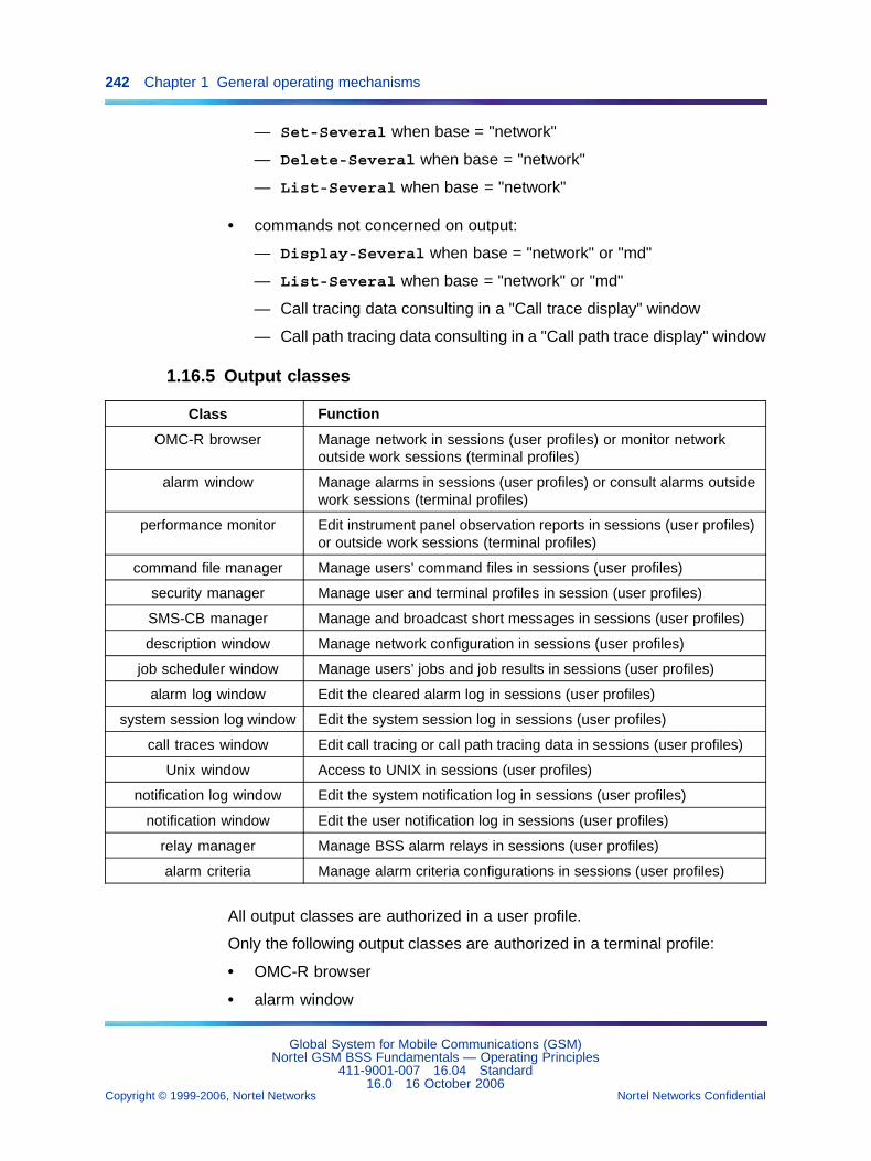
242 Chapter 1 General operating mechanisms
— Set-Several when base = "network"
— Delete-Several when base = "network"
— List-Several when base = "network"
• commands not concerned on output:
— Display-Several when base = "network" or "md"
— List-Several when base = "network" or "md"
— Call tracing data consulting in a "Call trace display" window
— Call path tracing data consulting in a "Call path trace display" window
1.16.5 Output classes
Class Function
OMC-R browser Manage network in sessions (user profiles) or monitor networkoutside work sessions (terminal profiles)
alarm window Manage alarms in sessions (user profiles) or consult alarms outsidework sessions (terminal profiles)
performance monitor Edit instrument panel observation reports in sessions (user profiles)or outside work sessions (terminal profiles)
command file manager Manage users’ command files in sessions (user profiles)
security manager Manage user and terminal profiles in session (user profiles)
SMS-CB manager Manage and broadcast short messages in sessions (user profiles)
description window Manage network configuration in sessions (user profiles)
job scheduler window Manage users’ jobs and job results in sessions (user profiles)
alarm log window Edit the cleared alarm log in sessions (user profiles)
system session log window Edit the system session log in sessions (user profiles)
call traces window Edit call tracing or call path tracing data in sessions (user profiles)
Unix window Access to UNIX in sessions (user profiles)
notification log window Edit the system notification log in sessions (user profiles)
notification window Edit the user notification log in sessions (user profiles)
relay manager Manage BSS alarm relays in sessions (user profiles)
alarm criteria Manage alarm criteria configurations in sessions (user profiles)
All output classes are authorized in a user profile.
Only the following output classes are authorized in a terminal profile:
• OMC-R browser
• alarm window
Global System for Mobile Communications (GSM)Nortel GSM BSS Fundamentals — Operating Principles
411-9001-007 16.04 Standard16.0 16 October 2006
Copyright © 1999-2006, Nortel Networks Nortel Networks Confidential
.
1.17 Command file management 243
• performance monitor
1.17 Command file management1.17.1 Overview
The OMC-R Command File Manager allows system users to createcommand files to facilitate network configuration, reconfiguration, andmonitoring.
Instead of executing commands entered on a terminal, the user records thecommands in a file in the chronological order of execution.
1.17.2 Operating principles1.17.2.1 Creating a command fileA command file is created by activating the record mode and enteringcommands in Menu mode.
In active record mode, the commands are saved without being executed.Command syntax is checked as each command is entered.
A command file can invoke another command file. The default numberof nested calls is set to five, but it can be statically reconfigured. All thecommands authorized in the command domain defined in the user’s profileare accepted. Commands to create and delete user or terminal profilesare not usually authorized.
When the user deactivates the record mode, the file is added to the list ofcommand files managed on the OMC-R. It is identified by a file name. Thenewly created command file is saved in the OMC-R manager disk directoryselected by the user at the start of the command recording procedure.
A command file can be modified or deleted only by the user who createdthe file. It can be copied, displayed, and run by an authorized user (whencopied, that user has the same privileges as the owner of the file).
Notes:
• The Display / Set command cannot be used in record mode(its selection with the mouse has no effect). Use the Display (insession log) command instead.
• Only MMI commands can be recorded in a command file. Directivescannot be recorded.
• If a user closes a work session without deactivating the record mode,the command file that was being prepared is not created and all thepreviously recorded commands are lost.
Global System for Mobile Communications (GSM)Nortel GSM BSS Fundamentals — Operating Principles
411-9001-007 16.04 Standard16.0 16 October 2006
Copyright © 1999-2006, Nortel Networks Nortel Networks Confidential
.
244 Chapter 1 General operating mechanisms
1.17.2.2 Managing command filesCommand File Manager commands and directives are as follows:
• Display
This command displays the properties of a command file in a displaywindow opened for that purpose, that is:
— name of the command file owner
— date of file creation on the OMC-R
— date of last modification
— list of users authorized to copy, visualize, execute and display theproperties of the command file. The list is empty when the commandfile is created and can be updated using the Set command describedbelow.
— summary explaining the goal of the file
— list of $XXX parameters included in the file (see "Setting commandparameters" in the paragraph)
• Copy
— Copy file
This command copies a command file to the same directory, underthe name "<command_filename>.cpy". The copy belongs to theuser who made it.
— Copy
This directive, using the "drag & drop method" copies a command fileto another directory, under the name "<command_filename>.cpy".The copy belongs to the user who made it.
• Move
This directive moves a command file from one directory to another,using the "drag & drop" method. The file is copied to the new directorythen deleted from the old directory.
• Edit file
This directive displays the contents of a selected command file in theCommand file editor window from where it can be updated andexecuted.
• Run
This command starts a selected command file run without editing itbeforehand.
Global System for Mobile Communications (GSM)Nortel GSM BSS Fundamentals — Operating Principles
411-9001-007 16.04 Standard16.0 16 October 2006
Copyright © 1999-2006, Nortel Networks Nortel Networks Confidential
.
1.17 Command file management 245
This command can be used to create an associated job. The commandfile run is then delayed until the first execution date and time set by theuser (see Section 1.18.4.3 "Job scheduler" (page 256)).
• Abort
This directive stops a command file currently running. The file runcommand is identified by a dedicated serial number in session logs.
If the command to abort is a simple MMI command, the command filerun stops when that command is executed. If the command to abort isanother command file run command, the command file run stops whenthe last command in that file has been executed.
• Set
This command allows the owner of a command file to modify itsproperties (such as the list of authorized users).
• Rename file
This command changes the name of a command file without changingdirectories.
• Delete file
This command deletes a command file from a directory afterconfirmation.
If the file is running (see end of chapter), the file is deleted after the lastcommand in the file has been executed.
• Display file
This directive displays the contents of a selected command file in theCommand file editor window from where it can be executed but notupdated.
1.17.2.3 Editing command filesAll command files created on the OMC-R can be edited by their ownerbefore being run. The commands recorded in the file are displayed in Linemode syntax and can be modified according to Line mode syntax rules.
Line mode syntax The general rules of Line mode syntax are as follows:
Action - class: object = (id = ident); param = value; param = value; ...
• Action ............ command name (Create, Display, etc)
• class .............. object class (bsc, bts, etc)
• object = () ......... string of characters to insert unchanged
• id = ident .......... object identification sequence
Global System for Mobile Communications (GSM)Nortel GSM BSS Fundamentals — Operating Principles
411-9001-007 16.04 Standard16.0 16 October 2006
Copyright © 1999-2006, Nortel Networks Nortel Networks Confidential
.
246 Chapter 1 General operating mechanisms
• param ............ name of a command parameter
• value ............. parameter definition
A command is identified at the OMC-R by an "Action + class" combination.Object classes and commands are listed in NTP < 124 > and at the endof NTPs to < 128 >.
The following separators are used:
• - (hyphen) separates the action from the command object.
• : (colon) separates the command from its parameters.
• = (equal) separates an identifier or parameter name from its value.
• ; (semicolon) separates command parameters.
Parentheses can be used. If there is a space in a character string, the stringis written between quotes. For example:
Set - bsc: object = (bsc = "BSC 2"); bscName = BSC2
Object identification The elements that identify an object depending on ahigher level object are separated by an ampersand "&". Example:
Create - btsSiteManager: object = (bsc = 1 & btsSiteManager = 1); ...
List parameters A list is a variable number of elements separated by a"commercial &". Example:
mobileAllocation = 1 & 2 & 3
Group parameters A group is a fixed number of indivisible elementsseparated by a tilde. Example:
thresholdInterference = -100 ~ -90 ~ -80 ~ -70
Filter parameters A filter is a variable number of elements matchingmathematical criteria and linked through the following logical operators:
• = means "equal".
• > means "greater or equal".
• < means "less or equal".
• & defines a "logical and".
• | defines a "logical or".
• ! defines a "logical not".
Special commands
Global System for Mobile Communications (GSM)Nortel GSM BSS Fundamentals — Operating Principles
411-9001-007 16.04 Standard16.0 16 October 2006
Copyright © 1999-2006, Nortel Networks Nortel Networks Confidential
.
1.17 Command file management 247
• The format of a command that does not apply to an object is as follows:
Action: param = value; param = value; etc.
For example: Sleep: duration = 12
• The format of a multiple command that may apply to several objects isas follows:
Action - Several: object = (id = ident) ; scope = scopeValue; filter =filterValue; param = value; param = value; ...
"Several" is a keyword, "object" defines the node of objects concernedby the command, "scope" defines the subset of objects depending onthe node, "filter" defines the conditions in which the command applies,and "param" defines the command parameters.
For example:
— This command is used to unlock all bts object instances describingthe radio cells of a BSS at the same time:
Set - Several: object = (bsc = 1); scope = "whole sub-tree";filter = (objectClass = bts & administrativeState = locked);administrativeState = unlocked;
— This command is used to list all bts object instances describing theradio cells of a BSS created on the OMC-R:
List - Several: object = (bsc = 1); scope = (level = 2); filter =(objectClass = bts);
Logical operators that can be used to define the conditions in which thecommand applies are listed in the previous paragraph.
Setting command parameters Users can edit command files to updatecommand parameters.
For example, a command file containing a "Display bsc" command is asfollows:
Display - bsc: object = (bsc = 1)
If the command is run, the attributes of the BSC no. 1 are displayed.
Let’s modify the command and replace "1" with $BSCID. The command isnow as follows:
Display - bsc: object = (bsc = $BSCID)
Before starting the file run, the OMC-R manager recognizes the $ characterand prompts the user to enter the reference number of the BSC whoseattributes are required.
Global System for Mobile Communications (GSM)Nortel GSM BSS Fundamentals — Operating Principles
411-9001-007 16.04 Standard16.0 16 October 2006
Copyright © 1999-2006, Nortel Networks Nortel Networks Confidential
.
248 Chapter 1 General operating mechanisms
With one command file, the user can then display the attributes of any bscobject created in the OMC-R.
For instance, a BSS configuration file could be created in this way thatcontains the identifiers or names of all the network elements.
ATTENTIONAny string of alphanumerical, uppercase characters recorded in a command filethat begins with $ and ends with a space or a lowercase character is viewed as avariable when the command file is run.
Special-purpose commands The following commands are useful forcommand file purposes:
CAUTIONBSC 12000HC specificThe sleep command was specifically designed for the BSC12000HC. Attempting to use this command on the BSC 3000 candamage some of its files.
• Sleep: duration = xxx is used to stop the command file run forxxx seconds and delay execution of the commands that follow.
• Echo: text = blah blah blah is used to display the text "blahblah blah", which indicates the exact position of the command file run.
Lines of comments Lines of comments can be inserted. These linesalways begin with a "#" character and are ignored when the command file isrun.
Blank lines also can be inserted. These lines are ignored when thecommand file is run.
1.17.2.4 Running command filesThe Run command is used to execute the commands contained in acommand file in the order which they were recorded. The next command isrun only after the system response to the previous command.
The commands and the system responses are saved in session logs in thesame way as commands entered directly on the terminal.
The system assigns a line number to identify each command recorded ina command file.
Users can decide to start running a command file from a given line number.The commands recorded before the line number specified in the commandare not executed.
Global System for Mobile Communications (GSM)Nortel GSM BSS Fundamentals — Operating Principles
411-9001-007 16.04 Standard16.0 16 October 2006
Copyright © 1999-2006, Nortel Networks Nortel Networks Confidential
.
1.17 Command file management 249
Users can decide to stop or continue a command file run if an applicationerror is detected during the run. If the system detects any other type oferror, the command file run is stopped. The user is informed and theOMC-R supplies the incorrect command number.
The OMC-R can be configured so that, when an application returns an errorin response to a command, the command is re-run. The period betweentwo re-runs, the maximum number of re-runs, and the errors that can behandled that way are defined in static configuration data. This treatment haspriority over the user’s choice to stop or continue the command file runwhen an application error occurs.
1.17.2.5 Saving command filesThis directive is used to save the commands being edited in a new orpreviously created command file.
Saving commands in a previously created file (whether the file is the onebeing edited or another file) may generate a backup file version containingthe previously recorded commands (static configuration option).
1.17.3 File Execution time Duration (FED)1.17.3.1 PrinciplesThe File Execution time Duration tool (FED) estimates the duration of acommand file execution. This tool adds up durations of each command,using laboratory test results.
1.17.3.2 Command File Estimator plug-in
CAUTIONCustomer specificIndicates that specific equipment and specific software (such asspecific software in the BSC) dedicated to a specific application isused and that therefore the feature is not available for all standardGSM users.
The Command File Estimator is an OMC-R plug-in which is an enhancementof the FED. As a plug-in, it is integrated into the standard OMC-R graphicaluser interface (GUI).
1.17.4 Command file directory management1.17.4.1 PrinciplesAll command files created by OMC-R users are saved in subdirectories ofthe "root" directory on the OMC-R manager disks.
Global System for Mobile Communications (GSM)Nortel GSM BSS Fundamentals — Operating Principles
411-9001-007 16.04 Standard16.0 16 October 2006
Copyright © 1999-2006, Nortel Networks Nortel Networks Confidential
.
250 Chapter 1 General operating mechanisms
Each user can create a dedicated subdirectory to save the command filescreated during the user’s work sessions. Sub-subdirectories can also becreated.
1.17.4.2 Managing the directoriesThe following MMI commands are available:
• Create directory
Creates a new command file directory in the "root" tree.
• Rename directory
Changes the name of a command file directory in the "root" tree.
• Delete directory
Removes a command file directory from the "root" tree, afterconfirmation.
• List
Displays the contents of a command file directory in the "root" tree.Subdirectories and command files created in the selected directory areidentified by name.
1.18 User facilities1.18.1 Overview
User Facilities concern general operating aspects. They are largelyindependent of other OMC-R functions and include the following:
• system log services
• system time management
• job scheduler management
• inter-user mail facility
• on-line help
The SMS-CB and Command file management services are also userfacilities. These services are detailed in previous paragraphs.
1.18.2 System log services1.18.2.1 System logsThe OMC-R manages the following system logs:
• system notification log
• cleared alarm log
• system session log
Global System for Mobile Communications (GSM)Nortel GSM BSS Fundamentals — Operating Principles
411-9001-007 16.04 Standard16.0 16 October 2006
Copyright © 1999-2006, Nortel Networks Nortel Networks Confidential
.
1.18 User facilities 251
The system notification log stores all the notifications received orspontaneously issued by the OMC-R agent. This log is independent ofuser sessions and is kept up to date in real time by the Fault Managementfunction.
The cleared alarm log stores the alarms automatically ceased by the systemor manually ceased by users. This log is kept up to date in real time by theFault Management function.
The system session log stores all the information on user interactions withthe OMC-R during work sessions. It is kept up to date by the SecurityManagement function and contains the following information:
• login and logout requests accepted or not by the system
• commands executed during the sessions (commands refused becauseof syntax errors are not stored in the log)
• system response to commands
• system warning messages
System logs are stored in OMC-R disk files:
• Their capacity is set in the static configuration to store the last threedays’ information.
• They are systematically purged to hold only the most recent information.
Only authorized users may consult the system logs.
1.18.2.2 System notification logConnected users can consult the notifications generated in response to theunsolicited messages issued by the entities in the zone of interest defined intheir profile.
Within these limits, authorized users can consult the entire log or selectedportions of the log. The following criteria can be used to select notifications:
• notifications with given serial numbers
• notifications of a given type
• notifications containing a given fault number
• notifications involving a type of BSC model and equipment, BTS modeland equipment, or object (the user may also select a named equipmentor object)
• notifications generated at a given time or within a given period of time
• notifications generated in response to unsolicited messages issuedwithin a given period of time
Global System for Mobile Communications (GSM)Nortel GSM BSS Fundamentals — Operating Principles
411-9001-007 16.04 Standard16.0 16 October 2006
Copyright © 1999-2006, Nortel Networks Nortel Networks Confidential
.
252 Chapter 1 General operating mechanisms
If no criterion is selected, all notifications in the connected user’s zone ofinterest are displayed.
If optimization mechanism is activated, then the number of processedincoming notifications depends on CPU load.
1.18.2.3 Cleared alarm logConnected users can consult the alarm messages related to the entities inthe zone of interest defined in their profile.
Within these limits, authorized users can consult the entire log or selectedportions of the log. The following criteria can be used to select alarmmessages:
• alarm messages with given serial numbers
• alarm messages with a given severity
• alarm messages containing a given fault number
• alarm messages related to notifications of a given type
• alarm messages involving a type of BSC model and equipment, BTSmodel and equipment, or object (the user may also select a namedequipment or object)
• alarm messages generated at a given time or within a given period oftime
• alarm messages generated in response to unsolicited messages issuedwithin a given period of time
• acknowledged or unacknowledged alarm messages
• alarm messages acknowledged by a given user
• alarm messages ceased by a given user
• alarm messages ceased for a given reason
If no criterion is selected, all notifications in the connected user’s zone ofinterest are displayed.
If optimization mechanism is activated, then the number of processedincoming alarms depends on CPU load.
1.18.2.4 System session logAuthorized users can consult the entire log or selected portions of the log.The following criteria can be used to select the information:
• consultation of a user’s work sessions
• consultation of all user sessions opened on a given terminal
Global System for Mobile Communications (GSM)Nortel GSM BSS Fundamentals — Operating Principles
411-9001-007 16.04 Standard16.0 16 October 2006
Copyright © 1999-2006, Nortel Networks Nortel Networks Confidential
.
1.18 User facilities 253
• consultation of information recorded within a given period of time. Thiscriteria can be combined with either of the previous criteria, but the twoother criteria are mutually exclusive
If no criterion is selected, all the information stored in the log is displayed.
1.18.3 System time management1.18.3.1 PurposeMonitoring and resetting the reference date and time of the OMC-R agent isfundamental for all the network operating events in time, such as:
• time-stamping events (notifications and alarms)
• time-stamping observation reports
• job runs triggered by the OMC-R manager
1.18.3.2 System time settingSetting the OMC-R agent reference date and time is fundamental since thisinformation is broadcast to all the connected BSSs.
The user in charge must monitor the OMC-R agent reference date and timeclosely. These references are characterized as follows:
• The md object externalTime attribute defines the current OMC-R agentdate and time.
• The md object deltaUtc attribute defines the difference between thecurrent OMC-R agent time and the Greenwich reference.
When the current OMC-R agent date and time are updated, the new dataare broadcast to all managed BSCs. When the GMT difference is updated,the new value is transmitted to the OMC-R manager.
Changing the reference OMC-R agent date and time does not affect thedate and time data displayed in the "Session information" window, if open,which refer to the terminal internal clock.
When the statutory time changes (automatically reset on the OMC-Rmanager and agent), the new system references are broadcast to themanaged BSCs no later than TCLOCK1 (periodicity with which the OMC-Ragent controls the BSC time = one hour). Consult the note at the end ofthe paragraph and the BSC time control mechanism described in codano31001 in NTP < 032 >.
1.18.3.3 Managing system time differencesThe statutory time is automatically reset on the OMC-R manager and agent.
Global System for Mobile Communications (GSM)Nortel GSM BSS Fundamentals — Operating Principles
411-9001-007 16.04 Standard16.0 16 October 2006
Copyright © 1999-2006, Nortel Networks Nortel Networks Confidential
.
254 Chapter 1 General operating mechanisms
Since the new time is not transmitted to the BSCs immediately, a timedifference can exist between the OMC-R agent and a BSC at that time,which is highlighted by the following warning message:
Event: MAJOR SOFTWARE FAULTFault number: 31001BSC-OMC time difference greater than TCLOCK4
The user in charge has the following choices:
• Either wait for the next BSC time control by the OMC-R agent (everyTCLOK1 = one hour), when the new references are automaticallybroadcast to all the managed BSCs,
• Or execute the Synchronize bsc clock command on each BSC createdon the OMC-R to immediately broadcast the system reference dateand time to the managed BSCs.
1.18.3.4 Time serverThe feature “OMC-R Time Synchronization from an external NTP source(27018)”, introduced in V16.0, allows the time of several OMC-R hosts tobe adjusted from a single source. This single source can be a referenceatomic clock (through a local time server) or an external NTP (NetworkTime Protocol) server.
NTP is an Internet standard protocol used to synchronize the system clocksof networked workstations and servers to some time reference over TCP/IPnetworks. NTP uses UDP packets for data transfer.
The OMC-R server(s) can transmit the reference time they obtain toworkstations, BSCs, and PCUSNs connected to them.
Local time server
A local time server can be held on an OMC-R workstation. For redundancypurposes, two distinct OMC-R workstations are required. A local timeserver gets the reference time from an atomic clock through a radio clockbox. It is regularly polled for time by the OMC-R server(s) by means ofthe NTP protocol.
External NTP server
The reference time from an external NTP server can be obtained through agateway to an external network. This external network can include up to10 NTP servers. These servers are regularly polled for time by the OMC-Rserver(s) by means of the NTP protocol like the local ones.
Global System for Mobile Communications (GSM)Nortel GSM BSS Fundamentals — Operating Principles
411-9001-007 16.04 Standard16.0 16 October 2006
Copyright © 1999-2006, Nortel Networks Nortel Networks Confidential
.
1.18 User facilities 255
1.18.4 Job schedulerThe OMC-R Job scheduler allows users to execute deferred MMI commandruns by partnering management parameters to the command. The"command/management parameters" combination defines a job.
The Job scheduler is an efficient way to perform big jobs during off-peaksystem periods, or perform specific jobs at a given date or at regularintervals (setting the active alarm handling configuration, for example).
The Job scheduler is installed on the OMC-R servers. The scheduler, whichis the list of jobs created by users, is stored in a mirrored disk file so thatjobs are not lost when the active server switches over.
The scheduler contents are updated in real time according to usercommands (create, set, or delete a job) or internal OMC-R job schedulermanagement (automatic job deletion by the system, or deletion of a userprofile meaning that all the jobs created by the user are automaticallydeleted).
1.18.4.1 JobsThere types of jobs are defined: the occasional jobs, the repeated jobs overa given period, and the repeated jobs with no time limit set.
• An occasional job is run once at a given date and time. These jobs arewithdrawn from the scheduler after the run.
• A repeated job over a given period is run at regular intervals, starting ona given date and time. These jobs are withdrawn from the scheduler atthe end of the given period.
• A repeated job with no time limit set is run at regular intervals, startingon a given date and time, until the user decides to withdraw it fromthe scheduler.
A job is identified by name and contains the following information:
• command line
• name of the machine where the job is run (server or workstation)
• date and time of first run
• for repeated jobs: job run period, job activation state (newly created jobsare active by definition, but they can be set inactive by the user at anyother time), and date and time of next run (progressively calculated bythe system for successive job occurrences during the defined run period)
• for repeated jobs over a given period of time: date and time of automaticpurge (calculated by the system from the date and time of the last rundefined by the user)
Global System for Mobile Communications (GSM)Nortel GSM BSS Fundamentals — Operating Principles
411-9001-007 16.04 Standard16.0 16 October 2006
Copyright © 1999-2006, Nortel Networks Nortel Networks Confidential
.
256 Chapter 1 General operating mechanisms
Not all the machines declared to the OMC-R are allowed to run jobs (Xterminals and RACEs are usually excluded). The list of authorized machinesis defined in static configuration data.
1.18.4.2 Command lineThe command that references a job is defined in Line mode syntax. Forexample:
Display - bsc: object = (bsc = 2);
This command may reference a command file. For example:
Run - commandFile: object = (commandFile = "/root/brigitt e/test");
1.18.4.3 Job schedulerThe OMC-R Job Scheduler manages all the jobs created by users in realtime.
Job management On a machine, several jobs may be simultaneouslyrun. The maximum number N of jobs that can be simultaneously run isdefined in static configuration data.
When this maximum number is reached for a machine, the OMC-R delaysthe start of a new job that is ready to run. The following apply:
• If the new job is occasional, it is run no more than one minute after oneof the current jobs finishes running.
• If it is repeated, it is run at the date and time of the next scheduledoccurrence and the job owner is warned.
If a machine shuts down for any reason and a job is scheduled before themachine restarts, the following apply:
• An occasional job is executed as soon as possible after the machinerestarts.
• A repeated job is executed at the date and time of the next scheduledoccurrence after the machine restarts.
When the system date and time are set (see "System time management"),these data are forwarded to the Job scheduler. If the statutory time changes,a job may be run twice during the same night when clocks are set back ornot run at all when clocks are set forward.
A repeated job is only run if it is active when the next occurrence is due(administrationState attribute = "unlocked").
Global System for Mobile Communications (GSM)Nortel GSM BSS Fundamentals — Operating Principles
411-9001-007 16.04 Standard16.0 16 October 2006
Copyright © 1999-2006, Nortel Networks Nortel Networks Confidential
.
1.18 User facilities 257
A message is sent to the users’ mailbox when a job they created has beenexecuted. Users are also warned if one of their jobs could not be run andgives the reason (inactive job, run delayed, etc.).
User commands Job scheduler operations are detailed below.
Users can manage the jobs they create without any restrictions. Authorizedusers may also manage the other users’ jobs.
• Create
A job is created by defining the command to run and the parametersrequired by the OMC-R to manage the run as follows:
— job name (identifier)
— command to execute
— name of the machine where the job is run
— date and time of first job run
— for repeated jobs, period of execution, and date and time of thelast run if any
The job must not exist in the Job scheduler, the Line command syntaxmust be correct, and the machine must be authorized to run jobs.
When the command references a command file, the system does notcheck whether the file exists at this point (it is checked on the first joboccurrence).
After the create command is validated, the job is recorded in thescheduler.
By definition, a job newly created is active.
• Display / Display any
These commands allow connected users to display the characteristicsof a job they have created or any scheduled job.
The job is identified by name with the following information:
— name of the user who created the job
— command line to execute
— name of the machine where the job is run
— date and time of first run
— for repeated jobs, period of execution, activation state, and date andtime of next occurrence
— for repeated jobs over a limited period, date and time of last run
Global System for Mobile Communications (GSM)Nortel GSM BSS Fundamentals — Operating Principles
411-9001-007 16.04 Standard16.0 16 October 2006
Copyright © 1999-2006, Nortel Networks Nortel Networks Confidential
.
258 Chapter 1 General operating mechanisms
• Set / Set any
These commands allow connected users to update a job they havecreated or any scheduled job.
The job is identified by name. All the job parameters can be set with thiscommand, apart from the activation state.
The Set command is only validated if the date and time of the next runcalculated by the system from the data defined in the command arebefore the end date and time, whether or not these data are set.
The parameters of a running job cannot be updated.
• Set administrativeState / Set any administrativeS tate
These commands allow connected users to modify the activation stateof a job they have created or any scheduled job.
The job is identified by name.
The activation state of a running job cannot be updated.
Reminder: An inactive job is not run when its next occurrences are due.
• Delete / Delete any
These commands allow connected users to delete a job they havecreated or any scheduled job.
The job is identified by name. If it is running, the run is not interrupted.
These commands must be confirmed before the system validates themand can be used for all job types. They are useful for deleting repeatedjobs when the date and time of last run have not been defined.
The result of a job that is deleted from the scheduler is not erased (seebelow).
Reminder: The system deletes occasional jobs from the schedulerafter the run and deletes repeated jobs over a limited period from thescheduler on the calculated date and time.
• Abort running job / Abort any running job
These commands only concern jobs that are running and allowconnected users to abort a job they have created or any scheduled job.
The job is identified by name. Repeated jobs that are aborted are runon the next scheduled occurrence.
• List jobs (Line mode command)
This command displays the characteristics of all jobs created in theOMC-R.
All jobs created on the OMC-R are displayed in the "Job Scheduler"window on the terminal screen.
Global System for Mobile Communications (GSM)Nortel GSM BSS Fundamentals — Operating Principles
411-9001-007 16.04 Standard16.0 16 October 2006
Copyright © 1999-2006, Nortel Networks Nortel Networks Confidential
.
1.18 User facilities 259
• List running jobs (Line mode command)
This command displays the characteristics of all the jobs that arecurrently running on a machine at the time of the command.
If no job is running, the system displays an appropriate message.
All jobs currently running are identified by a special logo in the "JobScheduler" window on the terminal screen.
1.18.4.4 Job resultsPrinciples One job result references each scheduled job and contains allthe messages related to the successive job runs (executed commandsand system responses). The system assigns a job result the name of thejob it represents.
The OMC-R stores job results in mirrored disk files so that no informationis lost when the active server switches over. The system regularly purgesthe files to avoid overfilling the disks.
If a second job is created with the same name as a previous job and theprevious job result is still stored on disk, the result of the second job isrecorded in the same file.
User commands The operations on job results are detailed below.
• Display (any) job result contents
These commands display the result of a job created by the connecteduser or the results of any scheduled job.
• Delete (any) job result
These commands delete the result of a job created by the connecteduser or the results of any scheduled job.
The job is not deleted when the associated result is deleted.
1.18.5 Inter-user mail facilityThe OMC-R Mail function manages inter-user messages.
Users registered with the OMC-R have a mailbox that is allocated whentheir profile is created and stores all the user’s mail.
Users can send mail to selected users (identified by name) or all systemusers at one time.
If a user is working in a session when a message is delivered, a messageappears on the terminal and the mail can be read without closing thesession. Any mail that is delivered when the user is not connected isannounced the next time the user logs in.
Global System for Mobile Communications (GSM)Nortel GSM BSS Fundamentals — Operating Principles
411-9001-007 16.04 Standard16.0 16 October 2006
Copyright © 1999-2006, Nortel Networks Nortel Networks Confidential
.
260 Chapter 1 General operating mechanisms
The OMC-R Mail function allows all connected users to list, consult, print,and delete the messages in their mailbox, send new mail, or answer apreviously received message.
Users are prompted to purge their mailboxes at regular intervals to avoidoverfilling.
1.18.6 On-line helpUsers can consult the OMC-R On-line Help facility during work sessions toobtain information on each menu, button, or operating parameter displayedon the terminal screen.
Any item in an MMI window is associated with a text that explains itsfunction. After selecting the item and the appropriate option in the Helpmenu, the information on the selected item is displayed in a special windowon the terminal screen.
On-line help is not available on remote access terminals (RACEs).
1.19 Synchronization1.19.1 BTS Synchronization
PrinciplesBTS synchronization consists in synchronizing one BTS with another BTSinstead of with a BSC (through the Abis link). The principle is to synchronizeone or two BTSs, called slave BTSs, with the synchronization signalreceived from a third BTS, called master BTS, instead of from the Abis link
The BTS that synchronizes another BTS is called the master BTS. AnS8000 Compact Base Common Functions (CBCF) module or an S12000BTS can synchronize an S8000 CBCF module, an S12000, or a BTS 18000.
The master BTS receives the synchronization from the BSC using the Abislink (and generates its own GSM time as a regular BTS does) or from aGPS clock.
The BTS that is synchronized by the master BTS is called a slave BTS. Theslave BTS receives the synchronization and GSM time from an externalsignal coming from the master BTS using a new specific cable. The GSMtime that is received by the slave BTS is re--generated and sent to the TRXwithout delay, to ensure that the radio frames of the slave BTS are in phasewith the radio frames of the master BTS.
Global System for Mobile Communications (GSM)Nortel GSM BSS Fundamentals — Operating Principles
411-9001-007 16.04 Standard16.0 16 October 2006
Copyright © 1999-2006, Nortel Networks Nortel Networks Confidential
.
1.19 Synchronization 261
The new specific cable is a “Y” cable that diverts the signal sent by themain cabinet of the master BTS to its two extension cabinets towards thetwo slave BTSs. The cable is connected to the Base Common Functionsinterconnection (BCFICO) board of the slave BTS S8000 or S12000 or tothe Interface Module (IFM) board of the BTS 18000 slave.
The operator can detect whether the slave BTS is correctly synchronizedwith the master BTS by loking at the LEDs.
BenefitsBTS synchronization allows:
• large capacity site configuration by extension of S8000 and S12000colocalized sites,
• 1*1 reuse pattern, using optimized frequency hopping system betweensynchronized sites.
ParametersTwo specific parameters are associated with this feature:
• btsSynchroMode which tells in which mode the BTS operates (normal,master or slave),
• masterBtsSmId which gives the identifier of the master BTS.
For details on these parameters, refer to NTP <124>.
Loss of synchronizationIf a slave BTS loses its external synchronization (on the master), there is analarm on the OMC-R stating that synchronization is no longer guaranteed.The slaveBTS synchronizes itself on the BSC (using the Abis link) to avoidservice interruption.
ActivationThe operator activates BTS synchronization at the OMC-R.
The BTS synchronization is sent to the BTS in the SET EXTERNALCONTACT REQUEST message.
Full BTS synchronizationFull BTS synchronization consists in activating the master and slave modesby setting the btsSMSynchroMode parameter.
If the master BTS is synchronized using GPS, the GPS time is indirectlybroadcast to the slave BTSs. The cable that broadcasts the master timeto the slave BTSs introduces delays that are compensated at the slave
Global System for Mobile Communications (GSM)Nortel GSM BSS Fundamentals — Operating Principles
411-9001-007 16.04 Standard16.0 16 October 2006
Copyright © 1999-2006, Nortel Networks Nortel Networks Confidential
.
262 Chapter 1 General operating mechanisms
BTS level. To achieve this configuration, the possible values for thebtsSMSynchroMode parameter for the master can be GpsBurstSync ormasterGpsTimeSync. The values for the slaveBTSs are set to normal.
Full BTS synchronization can also be achieved by synchronizing 3BTSs using GPS. To achieve this configuration, the btsSMSynchroModeparametermust be set to gpsTimeSync.
BTSs must be on the same BSCThe synchronizing and synchronized BTS must be on the same BSC.
For a description of BTS reparenting in case of BTS synchronization, seethe description in NTP < 034 >.
1.19.2 Network synchronizationPrinciplesThe network synchronization feature is a standalone feature.
The network synchronization consists in using the network as a commonclock source for network synchronization.
The following synchronization modes are available:
• Burst synchronization
• Time synchronization
The burst synchronization consists in enslaving the network on a sourceclock and ensuring that all bursts are aligned in time.
The time synchronization consists in enslaving the network on a sourceclock and forcing the GSM time to be deduced from a unique source time.
A network is synchronized when its entities share a common timesource.GSMtime synchronization is not mandatory but all clocks must followthe same pulse (burst synchronization). The pulse reference is taken fromthe GPS system.
1.19.2.1 BenefitsThe main benefits are:
• the smaller number of frequencies needed
• the increased frequency load on hopping plans
ActivationThe operator activates network synchronization by setting the appropriatevalue of the btsSMSynchroMode parameter. The operator also specifieswhich mode is used for network synchronization: burst or time.
Global System for Mobile Communications (GSM)Nortel GSM BSS Fundamentals — Operating Principles
411-9001-007 16.04 Standard16.0 16 October 2006
Copyright © 1999-2006, Nortel Networks Nortel Networks Confidential
.
1.20 Introduction to OMC-R data server (SDO) 263
The activation (the value of the btsSMSynchroMode parameter) is directlytransferred from the OMC-R to the BTS in the SET EXTERNAL CONTACTREQUEST message.
1.20 Introduction to OMC-R data server (SDO)The OMC-R Data Server, or SDO, is installed by the manufacturer whenthe system is commissioned.
The SDO Data Server application is a communication interface between theOMC-R and the peri-OMC applications. It does the following:
• processes data records and radio network configuration parameters inan ASCII readable format:
— counters of the Fast Statistic Observation - OFS records
— counters of the General Statistic Observation - OGS
— counters of the PCUSN observation
— counters of the PCU/BSC observation
— call tracing records
— call path tracing records
— cellTiering records
— fault and stateChange notification records
— radio network configuration parameters
— zones of interest (ZI) of the connected workstations
— OMC-R session log
• transfers OMC-R data the following ways, depending on data types andSDO configuration parameters:
— periodically (up to one day)
— at start time (only for automatic transfer mode), to recover the currentday data records produced at the OMC-R level since the last SDOhas been stopped.
— on event reception: each time a data record is received by theOMC-R
— on demand: these transfers apply to data collection period definedas part of one or more days using the beginSearchTime and theendSearchTime input criteria.
• builds per-record reports for:
— observation data
Global System for Mobile Communications (GSM)Nortel GSM BSS Fundamentals — Operating Principles
411-9001-007 16.04 Standard16.0 16 October 2006
Copyright © 1999-2006, Nortel Networks Nortel Networks Confidential
.
264 Chapter 1 General operating mechanisms
• builds per-period transfers for:
— fault and stateChange notifications
• builds consolidated reports (daily or user-defined time interval) for:
— observation data
— call tracing data
— call path tracing data
— fault and stateChange notifications
• builds reports for:
— radio network configuration
— OMC-R system session log
— zone of interest
• provides the following administration facilities:
— start and stop
— suspend and continue
— delay management
— survey and defense mechanisms
— daily purge
— defense purge
— on-demand purge
— data archival
— log SDO activity
— automatic data file compression algorithm
• transform and stores data on radio distribution measurements (seeDistributions on radio measurements)
• transform and stores data on call drops (see Call drop analysis)
• transforms and stores interference matrix data (see Interference matrix)
For more details, see NTP <006> and NTP <130>.
1.21 Network level presence identification of eDRX, ePA and HePA1.21.1 Overview
This feature (SV1374.1 & 020247 - Network level identification of eDRX,ePA and HePA presence) is a 14.3 features.
Global System for Mobile Communications (GSM)Nortel GSM BSS Fundamentals — Operating Principles
411-9001-007 16.04 Standard16.0 16 October 2006
Copyright © 1999-2006, Nortel Networks Nortel Networks Confidential
.
1.21 Network level presence identification of eDRX, ePA and HePA 265
The feature consists in finding a way to differentiate in a system view eDRXfrom DRX and ePA and HePA from PA for maintenance purpose and Edgefeature implementation preparation.
1.21.2 Operating principlesThe differentiation can be done in adding three new equipments in the BTSPOD of the products:
• EDRX type: 0xC0
• EPA type: 0xC1
• HEPA type: 0xC2
Existing equipment types are the following:
• DRX type: 0x90
• PA type: 0x68
Event reports on Abis interface will then be sent with the correspondingequipments in the event_code.
StatusRsp with Hardware Config will also be fulfilled in function of thepresent equipments, eDRX or DRX and ePA, HePA or PA.
BTS starts with default equipments DRX and PA and update them infunction of the connection of the Edge equipments. Type of DRX and type ofPA is detected by the BCF by the mean of the BoardInitRsp message fromthe DRX; the equipments by default will be DRX and PA.
When the BCF detects the presence of a eDRX or a ePA or a HePA, thecopy of the DLU in RAM must be updated with eDRX or ePA or HePA. Theequipment table in the DRX Slave Manager table must be also updated witheDRX or ePA or HePA. Event reports and Status with Hardware Config mustbe built with eDRX or ePA or HePA.
When eDRX has never been connected, it is seen by the BTS by default asa DRX (and not a eDRX). When ePA has never been connected, it is seenby the BTS by default as a PA (and not a ePA)
When HePA has never been connected, it is seen by the BTS by default asa PA -and not a HePA- (from a status report and event report point of view ;from a power management point of view, it is seen as a "unknown type" PA).
When starting, default equipment are DRX and PA, on Enable TRXmessage, an Event DRX_LINK is sent to the BSC on DRX equipment (evenif a eDRX is present).
Global System for Mobile Communications (GSM)Nortel GSM BSS Fundamentals — Operating Principles
411-9001-007 16.04 Standard16.0 16 October 2006
Copyright © 1999-2006, Nortel Networks Nortel Networks Confidential
.
266 Chapter 1 General operating mechanisms
When eDRX is connected (after StatusRsp from DRX), end of fault event issent to the BSC on DRX equipment (BoardInitRsp message has not beenreceived yet) and on BoardInitRsp message.
eDRX and ePA or HePA equipments are used in the Status with HwConfigand in other Event Report messages that could appear.
1.21.3 ImpactsNo modification on HW/SW compatibility (mapping of TDMA Edge on EdgeeDRX and ePA or HePA will use another mechanism, type of DRX is notenough to decide if the TDMA could be mapped or not, ePA or HePA is alsonecessary to take the decision and BSC has no vision for the moment onequipments PA)
Existing alarms that can occur on the equipment DRX can now occur alsoon eDRX equipment. Existing alarms that can occur on the equipment PAcan now occur also on ePA and HePA equipments.
CODANO 1060 and 1067 can now accept new causes wordingcorresponding to the eDRX, ePA and HePA fault causes.
New equipment at OMC-R allow to identify the type of equipment to replacein case of failure: DRX or eDRX, PA or ePA or HePA.
Replacement of a DRX by a eDRX procedure : A Lock/Unlock TRX mustbe made to ensure the coherence of the notifications sent to OMC-R.Replacement of a (H)(e)PA procedure : A Lock/Unlock or a reset TRX mustbe made to ensure the coherence of the control of the number of HePAand PA in the BTS.
Notes:
1 Feature SV1374 identifies eDRX, ePA and HePA at a network level.
2 A BSS configuration which contains an OMC-R with feature SV1374and a BTS without feature SV1374 works.
3 A BSS configuration which contains an OMC-R without feature SV1374and a BTS with feature SV1374 does not work because the OMC-Rcannot display a Status with Hardware Configuration containingunknown equipment.
New equipment eDRX (0xC0), ePA (0xC1) and HePA (0xC2) have to beimplemented in the OMC-R in terms of event reports decoding and displayhardware decoding. The event report causes defined for the equipmentDRX and PA can occur now also on eDRX, ePA and HePA equipment.
Global System for Mobile Communications (GSM)Nortel GSM BSS Fundamentals — Operating Principles
411-9001-007 16.04 Standard16.0 16 October 2006
Copyright © 1999-2006, Nortel Networks Nortel Networks Confidential
.
1.22 Disaster recovery 267
When failure on a (e)DRX or a (H)(e)PA, the operator will arrive on site withthe right equipment to replace thanks to the differentiation mechanism.
BTS detects the presence of eDRX, ePA and HePA and modify the DLUcopy in RAM to update the corresponding equipment types. Abis Eventsand StatusRsp with Hardware Config are then fulfilled with eDRX or DRXand ePA, HePA or PA equipment.
1.22 Disaster recoveryIf a disaster occurs on an OMC-R, all of the supervision is lost on thatOMC-R. The disaster plan describes how an OMC-R can be reconfigured tominimize the amount of time a loss of supervision lasts when an OMC-Rfails.
The disaster plan is divided into the following three main parts:
• Configuration. Sites are configured to perform daily backup operationsas part of the disaster recovery plan process.
• Recovery. A recovery of the backed-up OMC-R configuration occurs ona spare configuration to replace the failed OMC-R.
• Site restoration. The site which failed is restored to normal operations.
Additional procedural information for the disaster recovery plan in availablein the NTP <006>.
Global System for Mobile Communications (GSM)Nortel GSM BSS Fundamentals — Operating Principles
411-9001-007 16.04 Standard16.0 16 October 2006
Copyright © 1999-2006, Nortel Networks Nortel Networks Confidential
.
268 Chapter 1 General operating mechanisms
Global System for Mobile Communications (GSM)Nortel GSM BSS Fundamentals — Operating Principles
411-9001-007 16.04 Standard16.0 16 October 2006
Copyright © 1999-2006, Nortel Networks Nortel Networks Confidential
.
269
Chapter 2GSM evolutions
2.1 General Packet Radio Service (GPRS)2.1.1 Introduction
The GPRS is a wireless packet data service which is an extension to theGSM network. It provides an efficient method to transfer data by optimizingthe use of network resources together with providing the mobility. The GPRSradio resources allocator allows to provide multiple radio channels to oneuser in order to reach high data user rate. Furthermore, one radio channelcan be shared by multiple users in order to optimize the radio resources.
Operators can offer Data Services based on GSM for applications such as:
• Corporate services, including e-mail, Fax, Internet & Intranet accesses,File transfer, Telecommuting services
• Fixed access, including e-mail, Fax, Internet access, File transfer
• Consumer oriented info based messaging, WAP, SIM toolkits, Java
• Telemetric type applications
The GPRS is available only for BSSs equipped with a BSC 12000HC orBSC 3000 and in cells whose transceiver architecture consists of eitherDCU4 or DRX, but are not mixed.
2.1.2 PrinciplesGPRS uses a packet-mode technique to transfer high-speed and low-speeddata and signalling in an efficient manner. GPRS optimizes the use of thenetwork and radio resources.
New GPRS radio channels are defined and the allocation of these channelsis flexible.
The radio interface resources can be dynamically shared:
• by the active users (for GPRS TSs only)
Global System for Mobile Communications (GSM)Nortel GSM BSS Fundamentals — Operating Principles
411-9001-007 16.04 Standard16.0 16 October 2006
Copyright © 1999-2006, Nortel Networks Nortel Networks Confidential
.
270 Chapter 2 GSM evolutions
• between speech and data services (GPRS TSs and speech TSs on thesame TDMA, see Section 2.1.5 "GSM/GPRS/EGPRS TSs dynamicsharing" (page 271))
2.1.3 Implementation2.1.3.1 New equipmentThe GPRS network architecture is implemented on the existing wirelessinfrastructure with the addition of the following network identities:
• on the BSS side
The Packet Control Unit Support Node (PCUSN) performs the functionslinked to GPRS traffic management.
• on the Core Network (new packet handling subsystem) side:
— The Serving GPRS Support Node (SGSN) performs securityfunctions and access control
— The Gateway GPRS Support Node (GGSN) provides interworkingwith external packet-switched networks.
The SGSN has the equivalent role as the MSC role in the NSS but forthe data domain. Moreover the HLR is enhanced with GPRS subscriberinformation.
The main functions of the SGSN include:
• detecting new GPRS mobile stations in its service area
• sending and receiving data packets to and from the mobile stations
• recording the location of mobile stations inside its service area
One of the main roles of the SGSN is to perform data packet routing.Another key role of the SGSN is mobility management. In addition to thesetwo key roles, the SGSN provides a number of other functionalities. Theseinclude ciphering and compression.
2.1.4 OA&M interfaces evolutionThe implementation of GPRS introduces new parameters, redefinessemantics for some existing parameters, and introduces new observationcounters. The parameters are described in the NTP <128> and the countersare described in this section.
2.1.4.1 New observation countersTwo types of new counters are introduced by the GPRS feature. These newcounters are described in the following sub-sections.
New BSS observation counters
• 1086/x (grpsRachRejectedSicd<x>)
Global System for Mobile Communications (GSM)Nortel GSM BSS Fundamentals — Operating Principles
411-9001-007 16.04 Standard16.0 16 October 2006
Copyright © 1999-2006, Nortel Networks Nortel Networks Confidential
.
2.1 General Packet Radio Service (GPRS) 271
• 1087/x (grpsImmAssRejectedSicd<x>)
• 1088/x (grpsPagingRejectedSicd<x>)
• 1812 (allocatedCircuitTs(TrZone)Cum/Ech/Max/Moy)
• 1813 (allocatedPacketTs(TrZone)Cum/Ech/Max/Moy)
Refer to these new entries in NTP < 125 >.
New PCUSN observation counters The PCUSN presence in the networkintroduces new PCUSN counters. The PCUSN observation consists in thetwo following groups:
• BSS observed counters
• PCUSN observed counters
The numbering of these new PCUSN counters is 150xx and 151xx.
Refer to these new entries in NTP < 125 >.
Synthetic counters Synthetic counters contain the data calculated fromraw counter data or other synthetic counter data. The calculation formulasare defined in configuration files.
2.1.5 GSM/GPRS/EGPRS TSs dynamic sharingThis feature (TF1121 - GSM/GPRS TSs Dynamic sharing) enables dynamicsharing between GSM and GPRS of the TSs on the Air interface. The mainbenefit is the increase of the efficiency of this interface.
2.1.5.1 PrinciplesFor GSM/GPRS networks, three types of radio TSs are defined. The typesare as follows:
• fixed GPRS radio TSs
These TSs are used in order to guarantee a minimal number of radioTSs allocated to GPRS in this option. The operator sets this numberat the OMC-R level.
• fixed GSM radio TSs
These TSs are only used for GSM mode.
• shared radio TSs between GSM and GPRS
These TSs are by default used in GPRS mode, thus given to the PCUSNat the cell configuration and preempted by GSM in case of lack of fixedGSM radio TSs.
Global System for Mobile Communications (GSM)Nortel GSM BSS Fundamentals — Operating Principles
411-9001-007 16.04 Standard16.0 16 October 2006
Copyright © 1999-2006, Nortel Networks Nortel Networks Confidential
.
272 Chapter 2 GSM evolutions
At the OMC-R the operator indicates the cell radio TSs which manageGPRS (channelType attribute of the channel object set to "pDTCH") and thecorresponding TSs on the Abis interface connected through the BSC to theAgprs interface. Thus the same number of Agprs TSs as GPRS allocatedradio TSs is reserved on the Agprs interface.
In case of lack of GSM radio TSs, the BSC starts a preemption procedureto allocate shared radio TSs for GSM. Moreover, when a shared radio TStemporarily allocated to GSM is released (end of GSM allocation due to endof call or handover), a reallocation procedure towards GPRS is started toincrease the GPRS capacity.
The EDGE dynamic allocation features a single cell to share one or morepacket data channels (PDCHs) on the air interface between EnhancedGPRS (EGPRS) and GPRS mobiles. With this feature, cells share on-airtimeslots and backhaul resources by multiplexing GPRS and EGPRSmobiles. The multiplexing feature can be introduced on every kind ofnetwork (GPRS only, EGPRS only and EGPRS/GPRS) without anyconstraints. There are no degradations of the service when only GPRS isused. Sharing on-air timeslots and backhaul resources improves resourceuse and increases capacity. No parameters are required for multiplexingEGPRS/GPRS.
2.1.5.2 ConfigurationThe implementation on the OMC-R interface is the following:
• on channel object:
The channelType parameter must be set as follows:
— "tchFull" value for GSM only TSs
— "pDTCH" value for GPRS only and shared TSs
• on bts object:
— radioAllocator parameter enables to choose whether "voice+datacircuit" or "voice + data circuit + packet data" is supported.
In a GSM-R V.15 specific context, radioAllocator should be set to"voice + data circuit + packet data" to allow both GPRS calls andAdvanced Speech Call Item (ASCI) calls in the same cell.
— minNbrGprsTs parameter defines the minimum number of GPRSTSs in the cell.
— gprsPreemption parameter allows (or not) PCUSN to send a PCUSNTDMA Nack Status message at the end of the preemption procedure.
Global System for Mobile Communications (GSM)Nortel GSM BSS Fundamentals — Operating Principles
411-9001-007 16.04 Standard16.0 16 October 2006
Copyright © 1999-2006, Nortel Networks Nortel Networks Confidential
.
2.1 General Packet Radio Service (GPRS) 273
— gprsPreemptionProtection parameter defines the protection timerused to reduce the load in case of NACK during the preemptionprocedure.
• on transceiver object:
— gprsPriority parameter defines TDMA capacity to manage GPRS.
2.1.6 RLC polling improvementThe GPRS/EDGE Radio Link Control (RLC) polling improvement featureprovides a way for the operator to modify the polling frequency used bythe PCUSN at the end of Temporary Block Flow (TBF) periods (when theprobability for uplink TBF setup is high). The polling frequency has an impacton the end-user’s perception of system reactivity for applications composedof many short transfers which alternate Uplink (UL) and Downlink (DL).
2.1.6.1 PrincipleBefore this feature was available, the polling frequency was fixed and setto 240 ms during the Keep Alive period, the DL pre-establishment periodand the DL preventive retransmissions period. During these periods, theMS waits 240 ms for the next polling occurrence to request a UL TBF.This waiting period can be reduced by increasing the polling frequency.Parameter "rLCPolling" was added to the OMC-R for this purpose. Refer toNTP <124> for its description and values.
2.1.6.2 Polling limitationIncreasing the polling frequency for a given MS reduces the availablebandwidth for other mobile stations partitioned on the same Time Slots(TS). In order to reduce TBF establishment time and have more bandwidthfor the UL TBF when established, the number of blocks used for polling isintentionally limited to 50% of the overall TS bandwidth, if at least one TBFis established on this TS. If no UL TBF is allocated on a TS, the pollingfrequency is only limited by the available bandwidth and the number ofmobile stations requesting polling.
2.1.6.3 Polling during keep aliveDuring the first 240 ms period of the Keep Alive period, the polling frequencyis controlled by a timer set to 240 ms (or 120 ms or 60 ms depending onthe rLCPolling parameter). After the first 240 ms period, polling is repeatedevery 240 ms up to the Keep Alive Timer expiration.
2.1.6.4 Polling during DL pre-establishment periodDuring the first 240 ms period of the DL pre-establishment period, thepolling frequency is controlled by a timer set to 240 ms (or 120 ms or 60ms depending on the rLCPolling parameter). After the first 240 ms period,polling is repeated every 240 ms up to the DL TBF pre-establishment timerexpiration.
Global System for Mobile Communications (GSM)Nortel GSM BSS Fundamentals — Operating Principles
411-9001-007 16.04 Standard16.0 16 October 2006
Copyright © 1999-2006, Nortel Networks Nortel Networks Confidential
.
274 Chapter 2 GSM evolutions
2.1.6.5 Polling during DL preventive retransmissions periodDuring preventive retransmission period, the polling frequency is controlledby a timer set to 240 ms (or 120 ms or 60 ms depending on the rLCPollingparameter). Note that the DL preventive retransmissions period is usuallyshorter than 240 ms (typically 140-180 ms); therefore if the timer isset to 240 ms, this may prevent any polling during the DL preventiveretransmissions period.
2.1.7 TBF establishment improvementsThis feature (TF1220 - TBF establishment improvements) enables todecrease the time for starting data transfer. More precisely, it enablesto decrease the uplink and downlink TBF (Temporary Block Flow)establishment time, in order to increase the data throughput.
2.1.7.1 PrinciplesThis aim is reached using different sub-features related to one or both TBFtypes (uplink and downlink):
Uplink TBF improvement
TF1220.4 fast uplink assignment: This sub-feature allows to start theuplink data transfer immediately. The PCUSN immediately allocates one TSwhen receiving an initial PACKET RESOURCE REQUEST message.
This sub-feature is always activated.
Downlink TBF improvement
TF1220.3 transfer non DRX mode: This sub-feature is used whena downlink data transfer occurs, just after the release of downlink TBF.More precisely, in case of downlink data packet reception at the PCUSNlevel during the non-DRX period, the PCUSN takes into account a timer(partly defined by the drxTimerMax parameter), and sends an IMMEDIATEASSIGNMENT message to the MS in non-DRX mode.
This sub-feature allows to:
• reduce the TBF establishment time by half a CCCH period
• make the TBF establishment time independent of the CCCHconfiguration in some specific cases
The duration of the CCCH period is directly linked to CCCH parameters andespecially the noOfMultiFramesBetweenPaging parameter.
Global System for Mobile Communications (GSM)Nortel GSM BSS Fundamentals — Operating Principles
411-9001-007 16.04 Standard16.0 16 October 2006
Copyright © 1999-2006, Nortel Networks Nortel Networks Confidential
.
2.1 General Packet Radio Service (GPRS) 275
TF1220.6 fast downlink assignment: When receiving an initial downlinkdata frame, the PCUSN starts data transfer as soon as possible (i.e. whenreceiving the IMMEDIATE ASSIGNMENT message by the MS + reactiontime). This sub-feature is always activated.
TF1220.7 downlink pre-establishment: At the end of an uplink datatransfer, when the last data block is received and acknowledged, thePCUSN immediately starts a downlink TBF and triggers a timer defined bythe upAckTime parameter (before the reception of LLC frame coming fromthe SGSN), in order to resume faster, downlink data transfer, if needed.
This sub-feature induces an increase of bandwidth and TFI use.
Nevertheless, as the downlink TBF is established without Lapd and CCCHmessages, this feature decreases:
• the BSC load the
• Lapd channel load
• the CCCH load
Uplink and downlink TBF improvement
TF1220.5 TBF keep alive algorithm: This sub-feature is used at the endof a downlink TBF, in order to resume data transfer faster in case of:
• uplink data request
• downlink data request
In case of downlink TBF, if the last data block is sent, the TBF is not releasedeven if the MS has acknowledged all data, in order to resume faster, uplinkor downlink data transfer, if needed.
At the end of a downlink TBF, this feature keeps the TBF alive during a perioddefined by a timer (dwAckTime parameter), instead of releasing immediatelyall associated resources, thus increases resource use (bandwidth and TFI).
However, since the MS has still an established TBF, there is no need ofLapd and CCCH messages to restart the data transfer. Thus this featuredecreases:
• the BSC load
• the Lapd channel load
• the CCCH load and avoid in some cases a supplementary CCCH radioTS
Global System for Mobile Communications (GSM)Nortel GSM BSS Fundamentals — Operating Principles
411-9001-007 16.04 Standard16.0 16 October 2006
Copyright © 1999-2006, Nortel Networks Nortel Networks Confidential
.
276 Chapter 2 GSM evolutions
2.1.7.2 ConfigurationThe implementation on the OMC-R interface is the following:
• on transceiver object:
— dwAckTime parameter (packetAckTime) enables to activate /deactivate the sub-feature TF1220.5 keep alive algorithm
— upAckTime parameter (packetAckTime) enables to activate /deactivate the sub-feature TF1220.7 downlink pre-establishment
• on bts object:
— drxTimerMax parameter enables to activate / deactivate thesub-feature TF1220.3 transfer non-DRX mode
Refer to these entries in NTP < 124 >.
Sub-features TF1220.4 fast uplink assignment and TF1220.6 fast downlinkassignment are always activated.
2.1.8 GPRS TBF establishment improvement: one phase accessThe GPRS "one phase access" feature allows the uplink Temporary BlockFlow (TBF) to start faster, which decreases the uplink TBF establishmenttime in order to increase the data throughput from an end-user point of view.
The GPRS "one phase access" feature is implemented in the V15.0 releaseand is only applicable to GPRS. This feature is not available for DCU2 andDCU4 dual channel units.
2.1.8.1 PrinciplesThis feature allocates resources requested by an uplink TBF at the receptionof a "One phase" Channel Request message and starts the uplink datatransfer as soon as possible.
2.1.8.2 GPRS one phase access feature activation parameterThis feature is activated at the OMC-R using the following parameter:
• onePhaseAccess:
— Object: bts
— Values: enable / disable
— Class: 2
— Default value: disable
If the one phase access feature is deactivated, the BTS manages all GPRSand EDGE Channel Requests as in previous version (if CCCH at BTS isactivated).
Global System for Mobile Communications (GSM)Nortel GSM BSS Fundamentals — Operating Principles
411-9001-007 16.04 Standard16.0 16 October 2006
Copyright © 1999-2006, Nortel Networks Nortel Networks Confidential
.
2.1 General Packet Radio Service (GPRS) 277
The PCUSN uses the PDCH Assignment Parameters procedure, in order toinform the BTS of the activation or deactivation of the one phase accessfeature.
2.1.8.3 Cell configuration and modification parameterThe default number of downlink TS is managed in the pCU2GConfCellelement (byte 11). The number of downlink TS can be changed at theOMC-R using the following parameter:
• onePhaseDnMsCapability
— range: 1..255
— default value: 1
Values 1 to 8 are significant, but values 0 and 9 to 255 must beinterpreted as the default value by the PCUSN.
2.1.8.4 GPRS one phase access feature PCUSN countersThe following PCUSN counters are associated with the GPRS "one phaseaccess" feature:
• pcuChannelRequestOnePhase
• pcuUpTbfImmediateAssignmentOnePhase
• pcuContentionFailureOnePhase
Refer to NTP <125> for a description of these counters.
2.1.9 Extended uplink TBFThe "Extended Uplink TBF" feature (22915), introduced in V15.1, enablesthe uplink TBF (Temporary Block Flow) to be extended at the end of anuplink data transfer so that another uplink transfer can begin immediatelyafterwards.
This feature is defined in the 3GPP Release 4 (TS 44.060). It is mandatoryfor 3GPP Release 4 terminals and optional for the network.
This feature enables uplink resources to the MS to be retained duringtemporary inactive periods (when the MS has no RLC data blocks to send).During such periods, the network keeps allocating UL radio blocks to the MSso that it can send new RLC data blocks as soon as they become available.In this case, the MS is said to be operating in extended UL TBF mode.However, even in this mode, after a certain period of inactivity (during whichthe MS has sent no RLC data blocks), the uplink TBF is released by thePCUSN (at a point determined by the PCUSN).
Global System for Mobile Communications (GSM)Nortel GSM BSS Fundamentals — Operating Principles
411-9001-007 16.04 Standard16.0 16 October 2006
Copyright © 1999-2006, Nortel Networks Nortel Networks Confidential
.
278 Chapter 2 GSM evolutions
Without the feature, all resources are released at the end of an uplink TBF.Consequently, there will be a set-up time for the next uplink transfer. In thiscase, the MS is said to be operating in non-extended UL TBF mode.
The parameters nwExtUtbf, extUtbfNoData, tNwExtUtbf, tUsfExt, nUsfExt,onlyExtUtbf, and fullD1Ka are associated with this feature. See also thedescriptions of these parameters in NTP <124>.
2.1.10 Full Keep AliveThe "GPRS/EDGE Full Keep Alive" feature (28111), introduced in V15.1,enables pre-Release 4 terminals, operating in non-extended UL TBFmode, to increase their UL throughput by preserving DL TBF at UL TBFestablishments.
The feature increases throughput by decreasing set-up times and "saving"UL blocks. This feature is a consequence to the feature Extended UplinkTBF (described in Section 2.1.9 "Extended uplink TBF" (page 277)).
Without the feature, during an UL TCP transfer, a short DL TBF is set upto carry the TCP acknowledgements. This increases the set-up time and"wastes" UL blocks when sending control blocks for these TBF. Such controlblocks include Packet Control Acknowledgement messages respondingto the receipt of the DL TBF establishment requests (for example, PacketDownlink Assignment messages), or Packet Downlink Ack/Nack messagesresponding to the receipt of the DL TBF release requests (last data blockswith FBI=1 and RRBP).
2.1.11 Disabling TBF Keep Alive during GMM procedureThe "Disabling TBF Keep Alive during GMM procedure" feature (23038),introduced in V15.1, enables the MS to disable DL Keep Alive during aGMM (GPRS Mobility Management) procedure.
GMM procedures between the MS and SGSN result in the establishment ofshort TBFs which are followed either by a "DL TBF pre-establishment" or a"DL Keep Alive" procedure. During these latter 2 procedures, if NMO1 is notactivated, the MS is not reachable and cannot receive CS-paging. In thecase of "DL TBF pre-establishment" procedure, this can be 0.5 seconds. Inthe case of a a "DL Keep Alive" procedure, this can be 2.5 seconds.
The tGmmKeepAlive parameter is used to disable/enable and configure thefeature. See also the description of this parameter in NTP <124>.
Global System for Mobile Communications (GSM)Nortel GSM BSS Fundamentals — Operating Principles
411-9001-007 16.04 Standard16.0 16 October 2006
Copyright © 1999-2006, Nortel Networks Nortel Networks Confidential
.
2.1 General Packet Radio Service (GPRS) 279
2.1.12 GPRS sleepy cells Step 1: automatic detection and recoveryUp to V14 BSS version, some configuration problems or sub-systemcomponent failures may lead to what we call "GPRS sleepy cells". That isa cell on which GPRS is not operational but this state is not clearly statedto the operator.
The aim of this feature is to try an automatic recovery when the PCUSNdetects a problem that may be solved by a cell GPRS reconfiguration.
This recovery is done respectively through a cell GPRS reconfiguration.
2.1.12.1 PrinciplesThis feature modifies the BSS defense mechanism when the PCUSNdetects a problem that may be solved by a cell GPRS reconfiguration.
The problem detected by the PCUSN can be:
• BTS is not responding to CELL_GPRS_OPEN
• SGSN is not responding to BSSGP protocol message and BSSGPparapet NOK
• Cell unsynchronized on Agprs interface
• Pdch Assign Param procedure failure
• Incomplete config received from BSC
This defense is based on a message to the operator and a reconfigurationof the faulty entity in order to recover as soon as possible the GPRS service.
2.1.12.2 Main defense mechanismsGPRS service closing consists in disabling GPRS in MS using BCCHsys_info messages:
• System information 13 with empty content: the BTS stops broadcastingSI13 messages to the MS
• System information 3 and 4 (and 7 and 8 if necessary): deactivateGPRS broadcast indicator
A cell_GPRS_close message is also sent from the PCUSN to the BTS ifnecessary (cell_open previously sent). On receipt of this message, the BTSstops counters and the Abis GSL link is disabled.
2.1.13 Configure sending of SI13 and SI2Quater on Ext or Normal BCCHThis feature (27318) allows System Information 13 (SI13) and SystemInformation 2 Quater (SI2Quater) messages to be configured for normal orextended BCCH. The feature is implemented in the V15.0.1 release and isonly applicable for GPRS.
Global System for Mobile Communications (GSM)Nortel GSM BSS Fundamentals — Operating Principles
411-9001-007 16.04 Standard16.0 16 October 2006
Copyright © 1999-2006, Nortel Networks Nortel Networks Confidential
.
280 Chapter 2 GSM evolutions
2.1.13.1 PrinciplesSI13 and SI2Quater broadcast information is sent to the BTS and MS inthe System Information 3 (SI3) message, in the SI3 rest octet InformationElement (IE).
This feature allows the operator to choose normal or extended BCCH tosend the SI13 and SI2Quater messages. Two new parameters were addedto the BSC DATA CONFIG table on label 64 "mobile specificity configuration"to allow the selection of normal or extended BCCH. See Section 2.1.13.2"BSC data configuration parameters" (page 280) for a description of theconfiguration parameters.
Sending system information messages on extended BCCH will add trafficon PCH/AGCH.
2.1.13.2 BSC data configuration parametersBit 9: SI13_position:
• 0x00 (default value): SYSTEM INFORMATION TYPE 13 message issent on BCCH Norm
• 0x01: SYSTEM INFORMATION TYPE 13 message is sent on BCCH Ext
Bit 10: SI2Quater_position:
• 0x00 (default value): SYSTEMINFORMATIONTYPE 2Quater messageis sent on BCCH Norm
• 0x01: SYSTEMINFORMATIONTYPE 2Quatermessage is sent onBCCH Ext
SI13_position and SI2Quater_position IE in the SI3 rest octet will be set bythe BSC according to the BSC data configuration value.
2.1.13.3 Feature benefitsThe following concerns are resolved by the feature:
• MS device issues
— If the MS cannot read SI13 messages when sent on extendedBCCH, prevents the MS from connecting to GPRS services.
— If MS cannot read SI2Quater messages when sent on normalBCCH, leads to MS reboot or CS calls set up failure.
• Both SI13 and SI2Quater
— If both SI13 and SI2Quater are sent on normal BCCH, the MS takesmore time to read system information, causing increased reselectiontime.
Global System for Mobile Communications (GSM)Nortel GSM BSS Fundamentals — Operating Principles
411-9001-007 16.04 Standard16.0 16 October 2006
Copyright © 1999-2006, Nortel Networks Nortel Networks Confidential
.
2.1 General Packet Radio Service (GPRS) 281
— The number of reselection attempts may increase for some MSwhen both SI13 and SI2Quater are sent on normal BCCH.
2.1.14 PS paging duplication on BSCThe "PS Paging duplication on BSC" feature (26186), introduced in V15.1,reduces the Agprs load due to PS paging in the Downlink direction.
Without this feature, PS paging duplication is done on the PCUSN side.
With this feature, PS paging duplication is done by the BSC instead of onthe PCUSN side. This reduces the number of paging commands sent onthe Agprs GSL (GPRS Signaling Link) link towards the BTS. There is aconsequent improvement in performance.
2.1.15 GRPS/EDGE Suspend and ResumeThe "GPRS/EDGE Suspend and Resume" feature (25155), introduced inV15.1, enables a class B MS to resume its GPRS service after suspensionwithout sending a new RA (Routing Area) Update request.
Every class B MS which is GPRS attached must suspend its GPRS servicewhen it enters dedicated mode. Dedicated mode includes handling a circuitcall, making an LA (Location Area) update, sending/receiving an SMS, etc.When it leaves dedicated mode, it resumes its GPRS service.
Without this feature, the GPRS service is resumed using an RA Updaterequest to establish a TBF over the PS domain. Both TBF establishmentand the RA Update procedure consume resources.
With the feature, the GPRS service is resumed using a GPRS Resumerequest. The MS does not need to perform an RA Update. This proceduresaves resources in the PDTCH and the PCUSN CPU. As less PCUSNprocessing is required for signaling, the PCUSN capacity for handlingdata traffic is increased. This feature also reduces the duration of the MSunavailability period to receive an incoming CS call.
The parameters suspendResumeActivation, tSuspendAck, and tResumeAckare associated with this feature. See also the descriptions of theseparameters in NTP <124>.
2.1.16 Implementing Network Mode of Operation 1 (NMO1)The "Network Mode of Operation 1 (NM01) (TF 1134.2)" feature (17635),introduced in V15.1, enables a class B mobile currently performing a datatransfer (GPRS service) to be paged for an incoming voice call (GSM) andsuspend the data transfer to accept the voice communication.
A number of interfaces are used by this feature. These are shown in Figure46 "Interfaces associated with the NMO1 feature" (page 282).
Global System for Mobile Communications (GSM)Nortel GSM BSS Fundamentals — Operating Principles
411-9001-007 16.04 Standard16.0 16 October 2006
Copyright © 1999-2006, Nortel Networks Nortel Networks Confidential
.
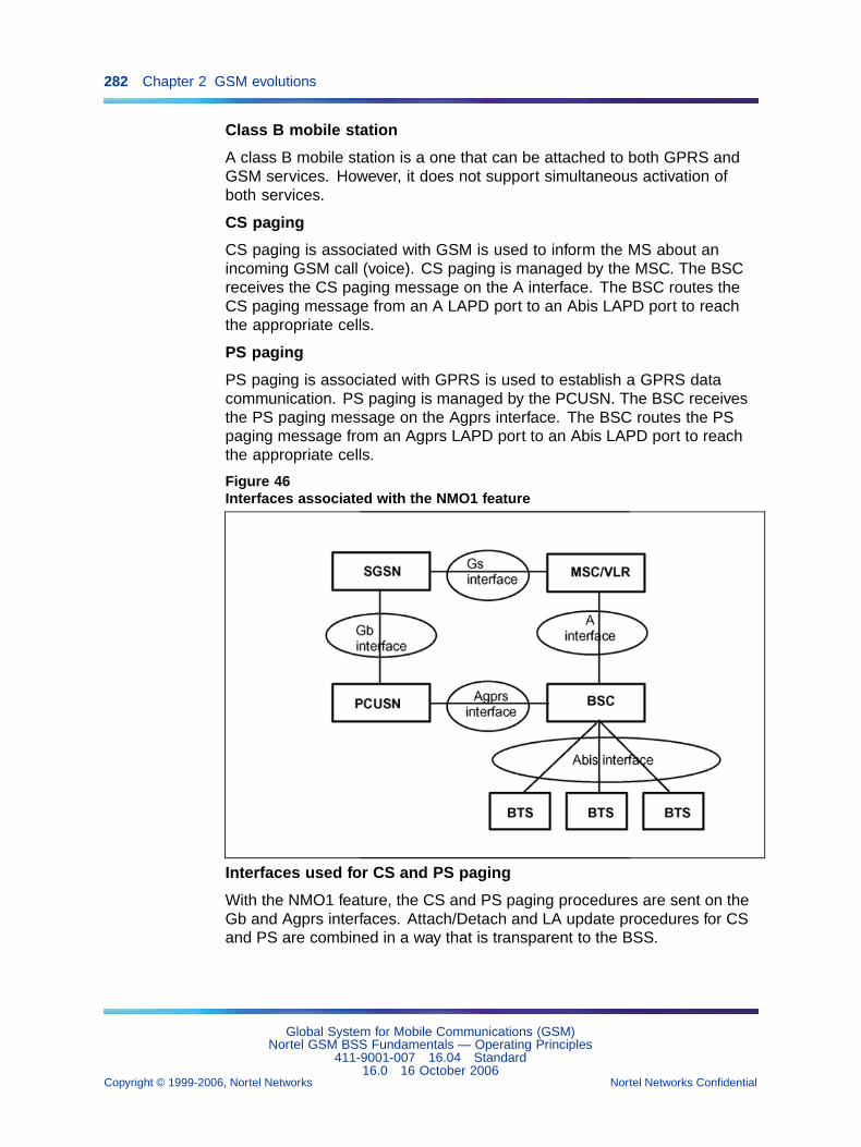
282 Chapter 2 GSM evolutions
Class B mobile station
A class B mobile station is a one that can be attached to both GPRS andGSM services. However, it does not support simultaneous activation ofboth services.
CS paging
CS paging is associated with GSM is used to inform the MS about anincoming GSM call (voice). CS paging is managed by the MSC. The BSCreceives the CS paging message on the A interface. The BSC routes theCS paging message from an A LAPD port to an Abis LAPD port to reachthe appropriate cells.
PS paging
PS paging is associated with GPRS is used to establish a GPRS datacommunication. PS paging is managed by the PCUSN. The BSC receivesthe PS paging message on the Agprs interface. The BSC routes the PSpaging message from an Agprs LAPD port to an Abis LAPD port to reachthe appropriate cells.
Figure 46Interfaces associated with the NMO1 feature
Interfaces used for CS and PS paging
With the NMO1 feature, the CS and PS paging procedures are sent on theGb and Agprs interfaces. Attach/Detach and LA update procedures for CSand PS are combined in a way that is transparent to the BSS.
Global System for Mobile Communications (GSM)Nortel GSM BSS Fundamentals — Operating Principles
411-9001-007 16.04 Standard16.0 16 October 2006
Copyright © 1999-2006, Nortel Networks Nortel Networks Confidential
.
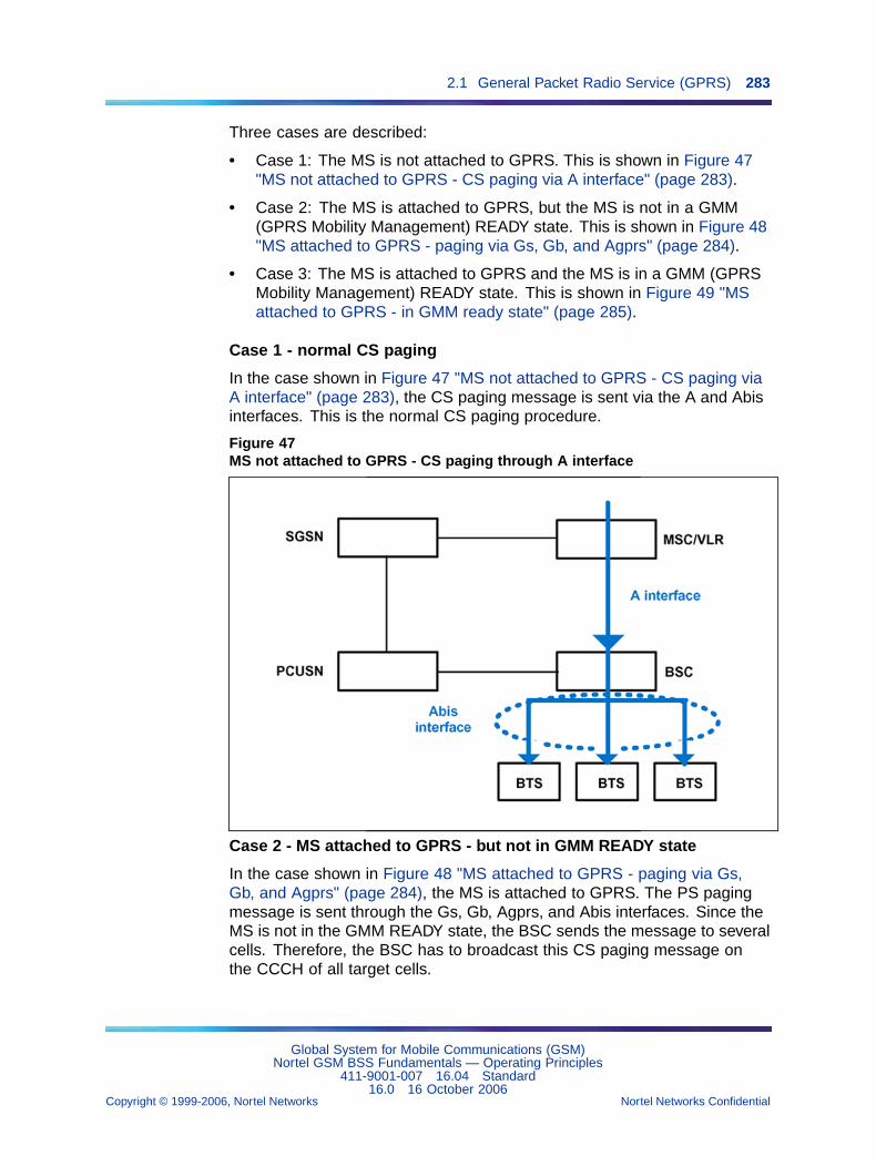
2.1 General Packet Radio Service (GPRS) 283
Three cases are described:
• Case 1: The MS is not attached to GPRS. This is shown in Figure 47"MS not attached to GPRS - CS paging via A interface" (page 283).
• Case 2: The MS is attached to GPRS, but the MS is not in a GMM(GPRS Mobility Management) READY state. This is shown in Figure 48"MS attached to GPRS - paging via Gs, Gb, and Agprs" (page 284).
• Case 3: The MS is attached to GPRS and the MS is in a GMM (GPRSMobility Management) READY state. This is shown in Figure 49 "MSattached to GPRS - in GMM ready state" (page 285).
Case 1 - normal CS paging
In the case shown in Figure 47 "MS not attached to GPRS - CS paging viaA interface" (page 283), the CS paging message is sent via the A and Abisinterfaces. This is the normal CS paging procedure.
Figure 47MS not attached to GPRS - CS paging through A interface
Case 2 - MS attached to GPRS - but not in GMM READY state
In the case shown in Figure 48 "MS attached to GPRS - paging via Gs,Gb, and Agprs" (page 284), the MS is attached to GPRS. The PS pagingmessage is sent through the Gs, Gb, Agprs, and Abis interfaces. Since theMS is not in the GMM READY state, the BSC sends the message to severalcells. Therefore, the BSC has to broadcast this CS paging message onthe CCCH of all target cells.
Global System for Mobile Communications (GSM)Nortel GSM BSS Fundamentals — Operating Principles
411-9001-007 16.04 Standard16.0 16 October 2006
Copyright © 1999-2006, Nortel Networks Nortel Networks Confidential
.
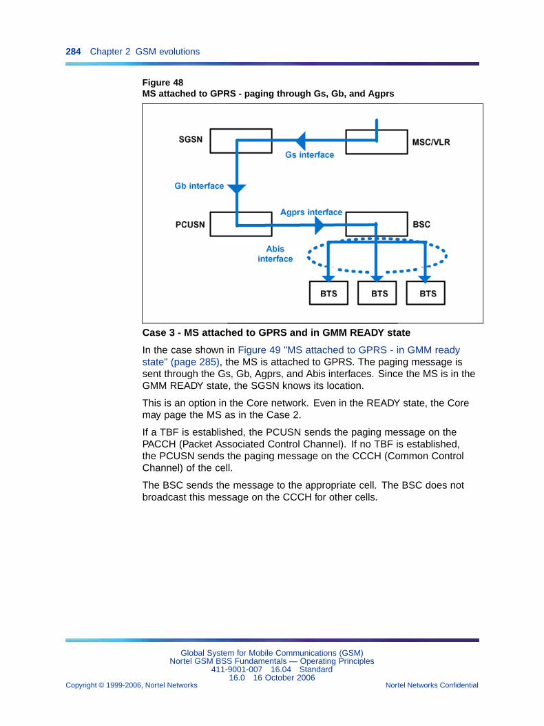
284 Chapter 2 GSM evolutions
Figure 48MS attached to GPRS - paging through Gs, Gb, and Agprs
Case 3 - MS attached to GPRS and in GMM READY state
In the case shown in Figure 49 "MS attached to GPRS - in GMM readystate" (page 285), the MS is attached to GPRS. The paging message issent through the Gs, Gb, Agprs, and Abis interfaces. Since the MS is in theGMM READY state, the SGSN knows its location.
This is an option in the Core network. Even in the READY state, the Coremay page the MS as in the Case 2.
If a TBF is established, the PCUSN sends the paging message on thePACCH (Packet Associated Control Channel). If no TBF is established,the PCUSN sends the paging message on the CCCH (Common ControlChannel) of the cell.
The BSC sends the message to the appropriate cell. The BSC does notbroadcast this message on the CCCH for other cells.
Global System for Mobile Communications (GSM)Nortel GSM BSS Fundamentals — Operating Principles
411-9001-007 16.04 Standard16.0 16 October 2006
Copyright © 1999-2006, Nortel Networks Nortel Networks Confidential
.
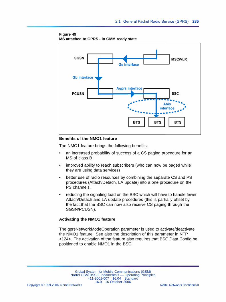
2.1 General Packet Radio Service (GPRS) 285
Figure 49MS attached to GPRS - in GMM ready state
Benefits of the NMO1 feature
The NMO1 feature brings the following benefits:
• an increased probability of success of a CS paging procedure for anMS of class B
• improved ability to reach subscribers (who can now be paged whilethey are using data services)
• better use of radio resources by combining the separate CS and PSprocedures (Attach/Detach, LA update) into a one procedure on thePS channels.
• reducing the signaling load on the BSC which will have to handle fewerAttach/Detach and LA update procedures (this is partially offset bythe fact that the BSC can now also receive CS paging through theSGSN/PCUSN).
Activating the NMO1 feature
The gprsNetworkModeOperation parameter is used to activate/deactivatethe NMO1 feature. See also the description of this parameter in NTP<124>. The activation of the feature also requires that BSC Data Config bepositioned to enable NMO1 in the BSC.
Global System for Mobile Communications (GSM)Nortel GSM BSS Fundamentals — Operating Principles
411-9001-007 16.04 Standard16.0 16 October 2006
Copyright © 1999-2006, Nortel Networks Nortel Networks Confidential
.
286 Chapter 2 GSM evolutions
2.2 Base Station Controller 3000 and TransCoder Unit 3000 (BSC3000 and TCU 3000)
2.2.1 OMN interfaces evolutionThe implementation of the BSC/TCU 3000 in the GSM system introducesnew objects and parameters seen from the OMC-R.
2.2.1.1 New objectsThe new object classes for an OMC-R V14 are the following:
• atmRm
• cc
• cem
• controlNode
• g3BscEqpt
• executableSoftware
• bsc2GEqpt
• g3Transcoder
• iem
• interfaceNode
• lsaRc
• mms
• omu
• sw8kRm
• tmu
• trm
• bscLog
2.2.1.2 New parametersThe following functional objects are defined:
• atmRm object
The atmRm object attributes are the following:
— administrativeState
— availabilityStatus
— operationalState
— upgradeStatus
— standbyStatus
Global System for Mobile Communications (GSM)Nortel GSM BSS Fundamentals — Operating Principles
411-9001-007 16.04 Standard16.0 16 October 2006
Copyright © 1999-2006, Nortel Networks Nortel Networks Confidential
.
2.2 Base Station Controller 3000 and TransCoder Unit 3000 (BSC 3000 and TCU 3000) 287
— positionInShelf
— shelfNumber
• cc object
The cc object attributes are the following:
— administrativeState
— availabilityState
— operationalState
— upgradeStatus
— positionInShelf
— shelfNumber
• cem object
The cem object attributes are the following:
— administrativeState
— availabilityStatus
— operationalState
— upgradeState
— standbyStatus
— positionInShelf
— shelfNumber
• controlNode object
The controlNode object attributes are the following:
— availabilityStatus
— interOmuEtherlinkOper
— operationalState
— rowPosition
• iem object
The iem object attributes are the following:
— administrativeState
— availabilityStatus
— CTU cable
— lsaRc Reference
Global System for Mobile Communications (GSM)Nortel GSM BSS Fundamentals — Operating Principles
411-9001-007 16.04 Standard16.0 16 October 2006
Copyright © 1999-2006, Nortel Networks Nortel Networks Confidential
.
288 Chapter 2 GSM evolutions
— numberOfEnabledHDLCPorts
— operationalState
— upgradeStatus
— standbyStatus
— positionInShelf
— shelfNumber
— lapdexists
— lsaPcmList
• interfaceNode object
The interfaceNode object attributes are the following:
— availabilityStatus
— operationalState
• lsaRc object
The lsaRc object attributes are the following:
— administrationState
— availabilityStatus
— lapdexists
— lsaPcmList
— operationalState
— positionInShelf
— shelfNumber
• mms object
The mms object attributes are the following:
— administrativeState
— availabilityStatus
— operationalState
— positionInShelf
— shelfNumber
— privateMmsOmuRef
— mmsUsag e
• omu object
Global System for Mobile Communications (GSM)Nortel GSM BSS Fundamentals — Operating Principles
411-9001-007 16.04 Standard16.0 16 October 2006
Copyright © 1999-2006, Nortel Networks Nortel Networks Confidential
.
2.2 Base Station Controller 3000 and TransCoder Unit 3000 (BSC 3000 and TCU 3000) 289
The omu object attributes are the following:
— administrativeState
— availabilityStatus
— portEthernetOperational
— portEthernetStatus
— X25Port0Operational
— X25Port1Operational
— port0X25Status
— port1X25Status
— operationalState
— upgradeStatus
— standbyStatus
— positionInShelf
— shelfNumber
• sw8kRm object
The sw8kRm object attributes are the following:
— administrativeState
— availabilityStatus
— operationalState
— upgradeStatus
— standbyStatus
— positionInShelf
— shelfNumber
• tmu object
The tmu object attributes are the following:
— administrativeState
— availabilityStatus
— numberOfEnabledHDLCPorts
— operationalState
— upgradeStatus
— positionInShelf
Global System for Mobile Communications (GSM)Nortel GSM BSS Fundamentals — Operating Principles
411-9001-007 16.04 Standard16.0 16 October 2006
Copyright © 1999-2006, Nortel Networks Nortel Networks Confidential
.
290 Chapter 2 GSM evolutions
— shelfNumber
• trm object
The trm object attributes are the following:
— administrativeState
— availabilityStatus
— operationalState
— upgradeStatus
— standbyStatus
— positionInShelf
— shelfNumber
• bsc2GEqpt
The bsc2GEqpt object attributes are the following:
— bsc2GEqptId
— tSCBNumber
— tSCBUse
— aLAIntState
• bsc3GEqpt
The bsc3GEqpt object attributes are the following:
— bsc3GEqptId
— bscReset
• bscLog
The bscLog object attributes are the following:
— bscLogId
— maxNbrConsMess
• executableSoftware-
The executableSoftware object attributes are the following:
— executableSoftwareId
— executableSoftxareName
— RelatedSoftwares
— configRefList
Global System for Mobile Communications (GSM)Nortel GSM BSS Fundamentals — Operating Principles
411-9001-007 16.04 Standard16.0 16 October 2006
Copyright © 1999-2006, Nortel Networks Nortel Networks Confidential
.
2.3 Location services 291
— bscList
— softwareLabel
2.3 Location services2.3.1 Introduction
The objective of this feature is to allow the GSM network to geographicallyposition of Mobile Stations (MSs).
Nortel offers 3 solutions:
• NSS-based solution (supported in V16.0 for compatibility reasons)
• Tandem-hybrid solution (replaced by the BSS-based solution in V16.0)
• BSS-based solution (V16.0 solution)
The Tandem-hybrid solution is also known as the “Multi-SSN Lb” solution.
Each solution is described below.
2.3.2 NSS-based solutionThe NSS-based solution enables the SMLC (Serving Mobile LocationCenter) to be connected to the MSC, in order to locate the mobile throughthe Ls and the A interface. This implementation is present on BSC 3000and BSC 12000HC.
In this solution Nortel provides a combined Gateway Mobile Location Centerand Serving Mobile Location Center (GMLC/SMLC) in a single platform, theMobile Location Server. This server is connected to the MSC. The BSSacts as a relay between the mobiles on one side and the Mobile LocationServer on the other side.
There are no specific overload protection mechanisms for LoCationServices (LCS) other than the general overload mechanisms. No specificnew counters or configuration parameters are introduced.”
In these software releases, there are no specific overload protectionmechanisms for LoCation Services (LCS) other than the general overloadmechanisms. Also, no specific new counters or configuration parametersare introduced.
LCS is logically implemented on the GSM structure through the additionof two network nodes, the Gateway Mobile Location Center (GMLC) andthe Serving Mobile Location Center (SMLC). Nortel has implemented bothnodes on the same platform called Mobile Location Server.
A generic LCS logical architecture is shown in LCS logical architecture.
Global System for Mobile Communications (GSM)Nortel GSM BSS Fundamentals — Operating Principles
411-9001-007 16.04 Standard16.0 16 October 2006
Copyright © 1999-2006, Nortel Networks Nortel Networks Confidential
.
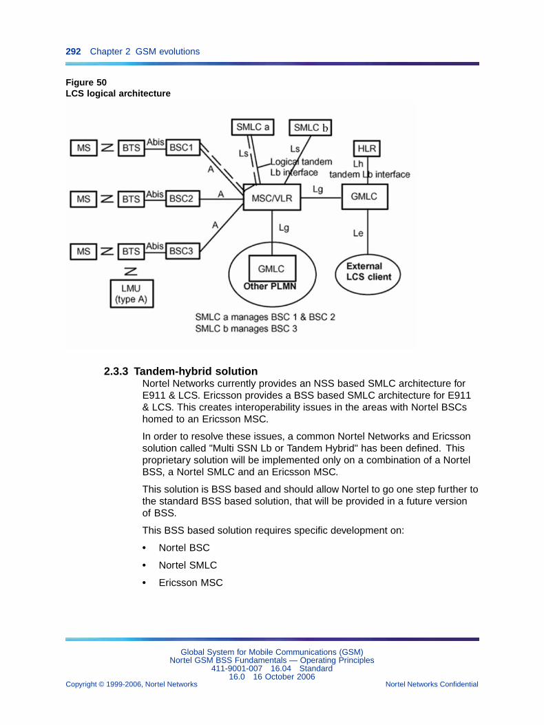
292 Chapter 2 GSM evolutions
Figure 50LCS logical architecture
2.3.3 Tandem-hybrid solutionNortel Networks currently provides an NSS based SMLC architecture forE911 & LCS. Ericsson provides a BSS based SMLC architecture for E911& LCS. This creates interoperability issues in the areas with Nortel BSCshomed to an Ericsson MSC.
In order to resolve these issues, a common Nortel Networks and Ericssonsolution called "Multi SSN Lb or Tandem Hybrid" has been defined. Thisproprietary solution will be implemented only on a combination of a NortelBSS, a Nortel SMLC and an Ericsson MSC.
This solution is BSS based and should allow Nortel to go one step further tothe standard BSS based solution, that will be provided in a future versionof BSS.
This BSS based solution requires specific development on:
• Nortel BSC
• Nortel SMLC
• Ericsson MSC
Global System for Mobile Communications (GSM)Nortel GSM BSS Fundamentals — Operating Principles
411-9001-007 16.04 Standard16.0 16 October 2006
Copyright © 1999-2006, Nortel Networks Nortel Networks Confidential
.
2.3 Location services 293
The aim of this section is to describe the new feature "20364: BSC supportfor Lb interface (Multi SSN or Tandem Hybrid) to Nortel SMLC throughEricsson MSC" solution and serve as a common reference to both Ericssonand Nortel for all future developments linked to this solution.
Depending on the SMS-C implementation on Nortel SMLC, Inter-OperabilityTesting (IOT) with the Ericsson MSC may be required. This will not beaddressed in this document.
This solution only impacts low-level communication layers between theBSC, MSC and SMLC (up-to BSSAP/BSSAP-LE). Application layers above(BSSLAP) are not impacted by this solution. Only the initiation and theending of the location procedure are modified.
From V15.1, the "Multi SSN Lb or Tandem Hybrid" feature is declared Endof Life (EOL) on BSC 12000HC. With the swap from BSC 12000HC to BSC3000, this feature is no longer needed or supported on BSC 12000HC. It isstill supported on BSC 3000 in V15.1.
A interface evolution
The Hybrid solution is a Nortel and Ericsson common solution. It will allowthe Nortel BSS to support the BSS based SMLC network architecture(Logical Lb interface support). The Lb logical interface is supported by theA and the Ls physical interfaces as well as a relay function implementedwithin Ericsson MSC.
New messages
The A interface supports some BSSMAP_LE messages, which weresupported as BSSMAP in NSS based solution. The following threemessages have been added:
• Perform_Location_Request
• Perform_Location_Response
• Perform_Location_Abort
O&M interface evolution
Moreover, the state of the new SSN won’t be sent to the OMC as there isno object SSN created at OMC level. Instead of a state change, there willbe a notification (warning) sent by the BSC to the OMC in order to give atBSC level the state of the SSN LCS (OK or NOK)
New alarms & notifications
Global System for Mobile Communications (GSM)Nortel GSM BSS Fundamentals — Operating Principles
411-9001-007 16.04 Standard16.0 16 October 2006
Copyright © 1999-2006, Nortel Networks Nortel Networks Confidential
.
294 Chapter 2 GSM evolutions
A new notification message identified as VAL_SYS_ANO_S7M_I_LCS issent by S7M (BSC 12000HC) to the OMC. This notification provides the stateof the SSN LCS and will be emitted on the object signalling link set whichdefines the A interface. Refer to < 128 > OMC-R User Manual - Volume 1 of3: Object and Fault menus for a description of notification messages.
New counters
Counters 1104 and 1106 have some new screenings dedicated to SSNLCS. Refer to NTP < 125 > for a description of these counters.
2.3.4 BSS-based solution2.3.4.1 PrinciplesThe BSS-based solution enables the SMLC to exchange messages directlywith the BSC through the Lb interface and thereby locate a mobile station.The BSC has to make the correlation between the communication managedwith the MSC and the location procedure required by the SMLC. Thissolution is available only on BSC 3000.
From V16.0, the BSS-based solution replaces the Tandem-hybrid solution(which emulates the Lb interface) on BSC 3000 and it is more efficient asregards the message flow.
The BSS-based solution supports the following four methods of MS location:
• cell_id
• Timing-Advance (also known as TA/NMR)
• U-TDOA
• A-GPS
2.3.4.2 Routes usedThe BSS-based solution relies on two distinct physical routes between theBSC and the MSC and the BSC and the SMLC. Each route supports onelink set:
• one for the A interface with the SCCP connections for thecommunications (DPC=MSC).
• one for the Lb interface with the SCCP connections destined to the LCSprocedure (DPC=SMLC).
Two pools of Signalling Links (SLK) are available on that route for the couple(DPC, SSN) MSC and the couple (DPC, SSN) SMLC.
Either distinct PCMAs or one common pool of PCMAs (outside the TCU)are used to convey the signalling links.
Global System for Mobile Communications (GSM)Nortel GSM BSS Fundamentals — Operating Principles
411-9001-007 16.04 Standard16.0 16 October 2006
Copyright © 1999-2006, Nortel Networks Nortel Networks Confidential
.
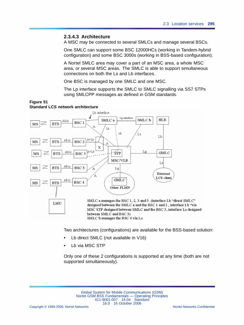
2.3 Location services 295
2.3.4.3 ArchitectureA MSC may be connected to several SMLCs and manage several BSCs.
One SMLC can support some BSC 12000HCs (working in Tandem-hybridconfiguration) and some BSC 3000s (working in BSS-based configuration).
A Nortel SMLC area may cover a part of an MSC area, a whole MSCarea, or several MSC areas. The SMLC is able to support simultaneousconnections on both the Ls and Lb interfaces.
One BSC is managed by one SMLC and one MSC.
The Lp interface supports the SMLC to SMLC signalling via SS7 STPsusing SMLCPP messages as defined in GSM standards.
Figure 51Standard LCS network architecture
Two architectures (configurations) are available for the BSS-based solution:
• Lb direct SMLC (not available in V16)
• Lb via MSC STP
Only one of these 2 configurations is supported at any time (both are notsupported simultaneously).
Global System for Mobile Communications (GSM)Nortel GSM BSS Fundamentals — Operating Principles
411-9001-007 16.04 Standard16.0 16 October 2006
Copyright © 1999-2006, Nortel Networks Nortel Networks Confidential
.
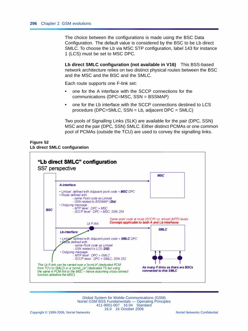
296 Chapter 2 GSM evolutions
The choice between the configurations is made using the BSC DataConfiguration. The default value is considered by the BSC to be Lb directSMLC. To choose the Lb via MSC STP configuration, label 143 for instance1 (LCS) must be set to MSC DPC.
Lb direct SMLC configuration (not available in V16) This BSS-basednetwork architecture relies on two distinct physical routes between the BSCand the MSC and the BSC and the SMLC.
Each route supports one F-link set:
• one for the A interface with the SCCP connections for thecommunications (DPC=MSC, SSN = BSSMAP)
• one for the Lb interface with the SCCP connections destined to LCSprocedure (DPC=SMLC, SSN = Lb, adjacent DPC = SMLC)
Two pools of Signalling Links (SLK) are available for the pair (DPC, SSN)MSC and the pair (DPC, SSN) SMLC. Either distinct PCMAs or one commonpool of PCMAs (outside the TCU) are used to convey the signalling links.
Figure 52Lb direct SMLC configuration
Global System for Mobile Communications (GSM)Nortel GSM BSS Fundamentals — Operating Principles
411-9001-007 16.04 Standard16.0 16 October 2006
Copyright © 1999-2006, Nortel Networks Nortel Networks Confidential
.
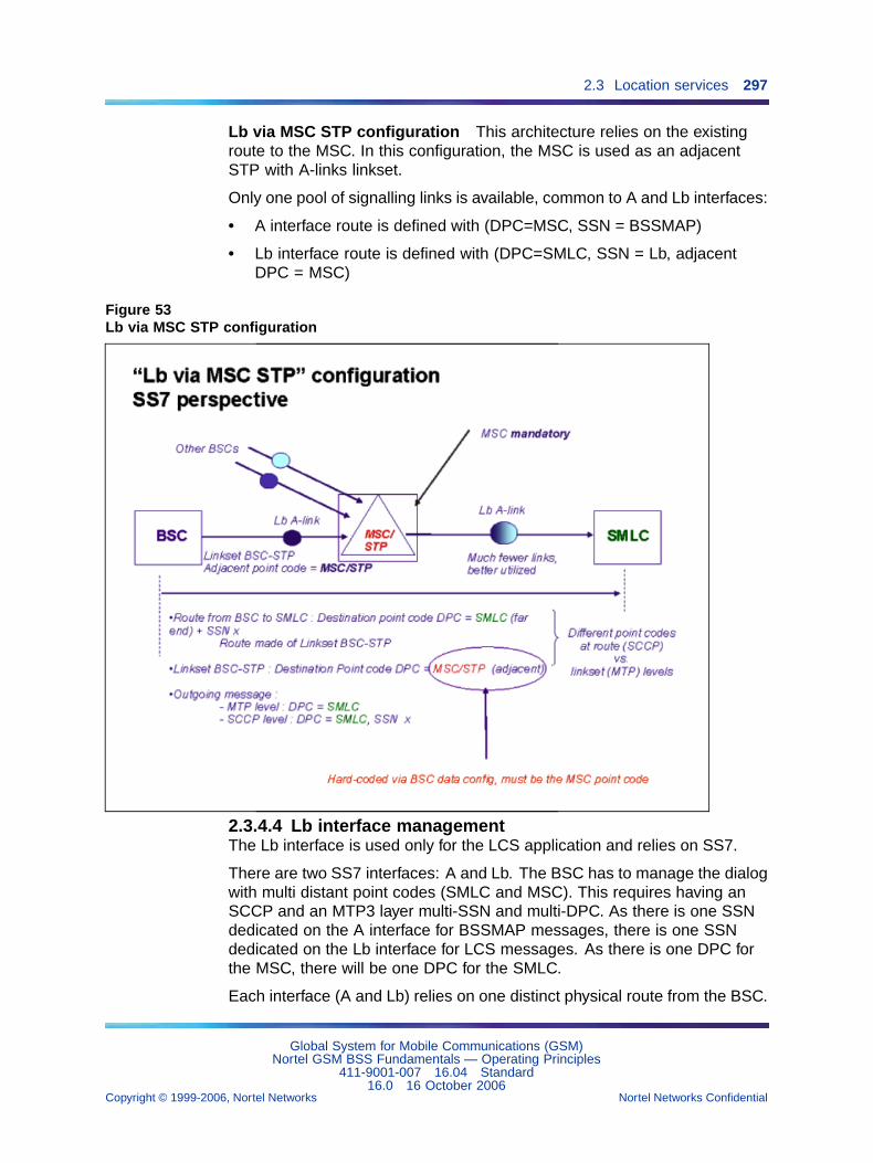
2.3 Location services 297
Lb via MSC STP configuration This architecture relies on the existingroute to the MSC. In this configuration, the MSC is used as an adjacentSTP with A-links linkset.
Only one pool of signalling links is available, common to A and Lb interfaces:
• A interface route is defined with (DPC=MSC, SSN = BSSMAP)
• Lb interface route is defined with (DPC=SMLC, SSN = Lb, adjacentDPC = MSC)
Figure 53Lb via MSC STP configuration
2.3.4.4 Lb interface managementThe Lb interface is used only for the LCS application and relies on SS7.
There are two SS7 interfaces: A and Lb. The BSC has to manage the dialogwith multi distant point codes (SMLC and MSC). This requires having anSCCP and an MTP3 layer multi-SSN and multi-DPC. As there is one SSNdedicated on the A interface for BSSMAP messages, there is one SSNdedicated on the Lb interface for LCS messages. As there is one DPC forthe MSC, there will be one DPC for the SMLC.
Each interface (A and Lb) relies on one distinct physical route from the BSC.
Global System for Mobile Communications (GSM)Nortel GSM BSS Fundamentals — Operating Principles
411-9001-007 16.04 Standard16.0 16 October 2006
Copyright © 1999-2006, Nortel Networks Nortel Networks Confidential
.
298 Chapter 2 GSM evolutions
As the SMLC, the MSC and the BSC are part of the same SS7 network, theset of SCCP parameters should be identical for the Lb and A interfaces.
This physical route goes through either specific or common PCMs. Twopools of Signalling Links (SLK) supported by these PCM circuits are defined:one pool for the A interface, the other one for the Lb interface. If one SLK islost for any reason (for example, loss of the PCM), the SCCP connectionsrunning on this SLK will be recovered on another SLK of the same pool.
The following possible values are added to the pcmType parameter:
• pcmA_Lb (4)
• pcmLb (5)
The existing pcmA-Lb (0) value is still used when the A and Lb interface areon the same PCMA out of the TCU (use of cross-connect equipment).
2.3.4.5 SCCP managementThe MS location procedure (cell_id method, Timing-Advance method,U-TDOA and A-GPS method) requires a specific SCCP connection betweenthe BSC and the SMLC per mobile.
The following SCCP messages are supported on the Lb interface:
• CR (Connection Request)
• CC (Connection Confirm)
• CREF (Connection REFusal)
• DT1 (Data Type 1)
• IT (Inactivity Test)
• UDT (Unit Data)
• RLSD (SenD ReLease)
• RLC (ReLease Confirm)
• SSP (SubSystem Prohibited)
• SST (SubSystem Test)
• SSA (SubSystem Allowed)
2.3.4.6 Data modelThe part of the data model of interest to feature 20365 is shown in thefollowing Figure.
Global System for Mobile Communications (GSM)Nortel GSM BSS Fundamentals — Operating Principles
411-9001-007 16.04 Standard16.0 16 October 2006
Copyright © 1999-2006, Nortel Networks Nortel Networks Confidential
.
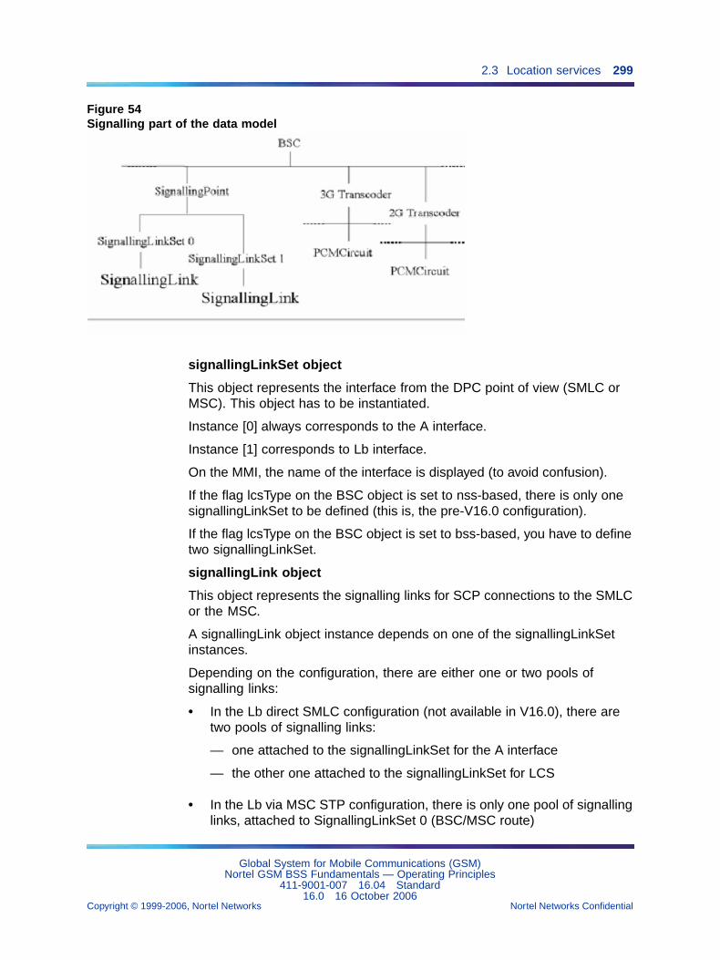
2.3 Location services 299
Figure 54Signalling part of the data model
signallingLinkSet object
This object represents the interface from the DPC point of view (SMLC orMSC). This object has to be instantiated.
Instance [0] always corresponds to the A interface.
Instance [1] corresponds to Lb interface.
On the MMI, the name of the interface is displayed (to avoid confusion).
If the flag lcsType on the BSC object is set to nss-based, there is only onesignallingLinkSet to be defined (this is, the pre-V16.0 configuration).
If the flag lcsType on the BSC object is set to bss-based, you have to definetwo signallingLinkSet.
signallingLink object
This object represents the signalling links for SCP connections to the SMLCor the MSC.
A signallingLink object instance depends on one of the signallingLinkSetinstances.
Depending on the configuration, there are either one or two pools ofsignalling links:
• In the Lb direct SMLC configuration (not available in V16.0), there aretwo pools of signalling links:
— one attached to the signallingLinkSet for the A interface
— the other one attached to the signallingLinkSet for LCS
• In the Lb via MSC STP configuration, there is only one pool of signallinglinks, attached to SignallingLinkSet 0 (BSC/MSC route)
Global System for Mobile Communications (GSM)Nortel GSM BSS Fundamentals — Operating Principles
411-9001-007 16.04 Standard16.0 16 October 2006
Copyright © 1999-2006, Nortel Networks Nortel Networks Confidential
.
300 Chapter 2 GSM evolutions
A signallingLink object instance is defined with:
• BSCid
• SignallinglinkPointid
• SignallingLinksetid
• SignallingLinkId
One signallingLink will support either some SCCP connections with theSMLC (OPC:BSC, DPC:SMLC, SSN:LCS), or some SCCP connections withthe MSC (OPC:BSC, DPC:MSC, SSN=BSSMAP).
pcmCircuit object
The PCM dedicated to the A interface (in previous releases) may now bededicated to A and Lb interface.
The pool of PCMs may be common.
2.3.5 Location methods2.3.5.1 Cell_id methodThis method applies only to the BSS-based solution and the BSC 3000.
When the communication is established (with a dedicated SCCP connectionreference) and as the MSC detects the mobile that needs to be located, theMSC sends a BSSMAP Perform Location message to the serving BSCfor the target MS.
On reception of this message, the BSC opens a new SCCP connection withthe SMLC dedicated for the location of that mobile. This SCCP is definedwith the DPC = SMLC and the SSN = LCS. The message BSSMAP_LEPerform location request is sent from the BSC to the SMLC encapsulated inthe SCCP connection request.
The LCS procedure starts between the SMLC and the BSC. There is nospecific message for the transfer of the cell_id. The SMLC already gets thecell_id of the MS in the message initiating the procedure.
The SMLC answers with a BSSMAP_LE perform location response (onthe SCCP cnx just opened).
The BSC sends back the BSSMAP Perform Location response to the MSCon the SCCP_ref dedicated to the communication.
On reception of the message, the BSC closes the SCCP connection withthe SMLC dedicated to LCS.
Global System for Mobile Communications (GSM)Nortel GSM BSS Fundamentals — Operating Principles
411-9001-007 16.04 Standard16.0 16 October 2006
Copyright © 1999-2006, Nortel Networks Nortel Networks Confidential
.
2.3 Location services 301
2.3.5.2 Timing-advance methodThis method applies only to the BSS-based solution and the BSC 3000.
The timing advance method (also known as the TA/NMR method) hasthe same initiation and the same release as the cell_id method. Thismethod requires the support of the two BSSMAP_LE connection orientedinformation messages on the Lb interface for the LCS procedure. Thesemessages are routed on the SCCP connection dedicated to LCS.
The SMLC sends the BSSMAP_LE connection oriented information thatincludes the messages TA request to the BSC on the SCCP connectiondedicated to LCS.
The BSC returns the current TA value and current serving cell for thetarget MS to the MSC in a TA response contained within a BSSMAP_LEconnection oriented information message. TheTA response must notinclude the latest measurement results received from the target MS for theserving and neighboring cells. If the BSC does not get the TA, it will send areset with a cause “failure for other radio related event”. The SMLC derivesa location estimate for the target MS based on received serving Cell_id, TAvalue, and other measurement results.
2.3.5.3 A-GPS methodThis method applies only to the BSS-based solution and the BSC 3000.
The A-GPS method requires the same initiation and release as the cell_idmethod.
The SMLC sends the BSSMAP_LE connection oriented informationmessage to the serving BSC containing an embedded BSSLAP MS positioncommand with an RRLP message. This is transferred to the BSC.
If the RLLP message is an Assistance Data message, the BSC transfers itto the BTS without any control or treatment. The BSC gives the embeddedRRLP message to the target MS inside an RR application informationmessage. Once the RR application message has been transferred, theBSC starts a positioning supervision timer. If the timer expires before thefinal response is received, the BSC returns a BSSMAP_LE connectionoriented information message to the SMLC containing the BSSLAP abortwith a cause of timeout BSC. This message of abort will be routed by theMSC to the SMLC.
If the BSC receives a response from the MS after the timer expires, the BSCdiscards the RRLP message just received. If the mobile is unable to performthe necessary measurements, or compute a location, a failure indicationidentifying the reason for failure is returned instead.
Global System for Mobile Communications (GSM)Nortel GSM BSS Fundamentals — Operating Principles
411-9001-007 16.04 Standard16.0 16 October 2006
Copyright © 1999-2006, Nortel Networks Nortel Networks Confidential
.
302 Chapter 2 GSM evolutions
Otherwise, the BSC forwards the RRLP message to the SMLC inside aBSSLAP MS position response message contained in a BSSMAP_LEconnection oriented information message to the SMLC. The BSC stopsthe supervision timer started earlier when the message is forwarded tothe SMLC.
2.3.5.4 U-TDOA methodThis method applies to the Tandem-hybrid, NSS-based, and BSS-basedsolutions, and to the BSC 3000
The SMLC sends the BSSMAP_LE connection oriented information thatincludes the message U-TDOA request to the BSC on the SCCP connectiondedicated to LCS.
The BSC starts a “delta_timer” (value given in the U-TDOA request) andreturns the channel description parameter for the target MS to the MSC ina U-TDOA response contained within a BSSMAP_LE connection orientedinformation message.
On reception of the BSSMAP_Perform_Location_Response, or ondelta-timer expiry, the BSC closes the LCS related SCCP connection.
The U-TDOA location method uses transmit energy to locate an MS on anexisting dedicated connection (SDCCH or TCH).
Channel assignment information is given by the BSC to the SMLC, thentransmitted to a set of Location Measurement Units (LMUs). These LMUsstart capturing and storing MS bursts. Each LMU determines a Time OfArrival (TOA) value and sends it to the Positioning Determination Entity(PDE).
LMUs are wireless devices (type A).
The PDE uses the received TOA values to calculate a geographic position.Information transfer between the PDE and the LMUs is independent fromthe BSC.
During the localization procedure, all changes in channel assignmentinformation is sent by the BSC to the SMLC. A timer called delta-timer isused to define the maximum time during which the BSC supervises thelocation request.
When a MS is close to a base station, the power control can be up to 36dB.Surrounding base stations may have difficulty listening to that MS. Thenumber of bursts required for U-TDOA positioning may be considerablyincreased.
Global System for Mobile Communications (GSM)Nortel GSM BSS Fundamentals — Operating Principles
411-9001-007 16.04 Standard16.0 16 October 2006
Copyright © 1999-2006, Nortel Networks Nortel Networks Confidential
.
2.4 EDGE 303
2.3.6 A-GPS Assistance data supportWith the "GPS Assistance data support over LS interface" feature (25363),introduced in V15.1, more information can be sent to an A-GPS capable MSto help it complete its GPS location measurements.
This information is sent to the MS during the A-GPS (Assisted-GlobalPositioning System) location procedure. The A-GPS assistance datamessages are part of the Radio Resource LCS Protocol (RRLP) usedbetween the MS and the Serving Mobile Location Center (SMLC). Theassistance data that the SMLC has decided to send or that the MS hasrequested, may be sent in one or more assistance data components. NeitherRRLP segmentation nor the LAPDm priority management feature is used.
The feature uses three new RRLP messages:
• RRLP (Assistance data)
• RRLP (Protocol error)
• RRLP (Assistance data Ack)
These messages are described in the following recommendation:
• 3GPP TS 44.031 Release 6 "Location Services (LCS) Mobile Station(MS)/Serving Mobile Location Centre (SMLC)" Radio Resource LCSProtocol (RRLP)".
This feature is available only if the BSC is working with an SMLC thatsupports the A-GPS location procedure. It is supported by BSC 3000. Itis not supported by BSC 12000HC.
2.4 EDGE2.4.1 Introduction
Enhanced Data for GSM Evolution (EDGE) is an extension of theGSM/GPRS Access network. It largely inherits the administration,maintenance and supervision of the currently deployed BSS. The GPRSCoding Schemes are enhanced with seven EDGE coding schemes (MCS2,MCS3, and MCS5 through MCS9) using two radio modulations (GMSK and8-PSK). These schemes increase the peak radio throughput of a carrier.(The EDGE throughput is three times greater than GPRS throughput). Tobenefit from the coding schemes, a BTS needs E-DRX and E-PA hardware.Extending the backhaul of a BTS allows it to benefit from the full rangeof schemes.
EDGE is part of the 1999 release of 3GPP specifications and is supportedby the 1997 release of SGSN. The BSS complies with the 1999 3GPPspecification on the radio interface.
Note that to benefit from EDGE features:
• BSC 3000 is required
Global System for Mobile Communications (GSM)Nortel GSM BSS Fundamentals — Operating Principles
411-9001-007 16.04 Standard16.0 16 October 2006
Copyright © 1999-2006, Nortel Networks Nortel Networks Confidential
.
304 Chapter 2 GSM evolutions
• eDRX and ePA are necessary on the BTS
2.4.2 Data backhaulWhen V12.4 introduced packet data services in the BSS, the radiothroughput was limited to 13.4 kbps. From V15, new EDGE coding schemesare managed from MCS1 up to MCS9 (59.2 kbps). Seven EDGE codingschemes greatly improve the capacity of EDGE backhaul functions andsupport higher data rates. The Abis and Agprs interfaces based on 16kbpsTS have been enhanced in order to manage this new throughput. EDGEalso provides a backhaul mechanism to increase capacity by routing dataindirectly, beyond its destination and back again to utilize more availableroutes, when doing so is more efficient, less expensive, necessary, orotherwise advantageous.
2.4.3 TDMA selectionIn V15.0, the maximum number of TDMAs of a cell that could supportEDGE channels was 1. In V15.1, all the TDMAs of a cell can supportEDGE channels.
Due to the Feature 25494 "EDGE Multiple TDMA" feature (25494),introduced from V15.1, the selection principles have been modified (asdescribed below).
2.4.3.1 Selection principles on PCUSNOnce an EDGE capable MS connects to the network, the PCUSN allocatesit a TDMA.
As far as EDGE is concerned, any TDMA can be of 2 types:
• No EDGE
• Full EDGE
For more details on these types, refer to description of theedgeDataServiceTyp e parameter in NTP < 124 >.
To benefit from the higher EDGE throughput, an EDGE MS should beallocated on EDGE capable TDMAs if possible.
To benefit from the higher EDGE throughput, an EDGE MS should beallocated on EDGE capable TDMAs if possible. The edgeFavor parameter,introduced in V15.0 to favor EDGE TDMA against GPRS TDMA, is used toassign a higher offer to an EDGE TS for an EDGE MS. The parameter isset on a per TDMA basis and it reflects the relative throughput that can beobtained with EDGE on that TDMA.
Global System for Mobile Communications (GSM)Nortel GSM BSS Fundamentals — Operating Principles
411-9001-007 16.04 Standard16.0 16 October 2006
Copyright © 1999-2006, Nortel Networks Nortel Networks Confidential
.
2.4 EDGE 305
The selection of a TDMA depends on the type of the TDMA and on thevalue of the edgeFavor parameter. It also depends on the GPRS and EDGEload in the TDMA. In V15.1, where multiple EDGE TDMA can be configured,the edgeFavor parameter can also be used to favor one EDGE TDMAcompared to another EDGE TDMA.
Allocator principles The Allocator principles for TS selection are:
• In the case of an equal offer for 2 TDMAs, the PCUSN will select anEDGE capable TDMA for an EDGE capable MS.
• In the case of an equal offer for 2 TDMAs, the PCUSN will select firsta GPRS-only TDMA for a GPRS capable MS.
2.4.3.2 Selection principles on BSCFrom a BSC point of view (the PCUSN uses the reverse way), shared radioTSs are allocated using the following criteria:
• a TDMA priority linked to the requested service
• the TDMA number
• the TS number
This algorithm is not changed for GPRS-only TDMAs.
In order to avoid pre-emption of EDGE TSs, the EDGE TDMAs are assigneda "Super High" priority by the BSC. This means that they are assigned inpriority to PCUSN. Note that a TDMA is declared as being EDGE using theedgeDataServiceType parameter.
Allocator principles The allocation order is:
• an EDGE TDMA (according to the GPRS priority)
• a GPRS TDMA (according to the GPRS priority)
• the TDMA number
• TS number
Pre-emption follows the reverse order.
2.4.3.3 Allocation in case of lack of resourcesWhen an EDGE capable MS is allocated in GPRS mode because of lack ofresources, a specific counter pcuEdgeDowngradedTbf is increased.
The MS is treated as a GPRS MS up to the end of the TBF (note that thespecification does not allow a GPRS TBF to be modified to an EDGE TBFor vice-versa). It means that the MS is considered as a standard GPRS MSand all the counters related to GPRS are increased accordingly.
Global System for Mobile Communications (GSM)Nortel GSM BSS Fundamentals — Operating Principles
411-9001-007 16.04 Standard16.0 16 October 2006
Copyright © 1999-2006, Nortel Networks Nortel Networks Confidential
.
306 Chapter 2 GSM evolutions
In case of Full Duplex establishment, the PCUSN always selects the samemode (GPRS or EDGE) rather than the already established TBF.
When a TBF is established in EDGE mode, the MS will be constrained bythe PCUSN Allocator for an EDGE capable TDMA.
2.4.3.4 Multi-slot classOnce an EDGE capable MS has been allocated in EDGE mode, thePCUSN allocates a set of TSs according to the MS EDGE Multi-slot class.Note that the MS EDGE Multi-slot class can be different from the GPRSMulti-slot class.
2.4.4 Link adaptationTo improve end-user throughput and the efficiency of network radioresources, a link adaptation mechanism matches the selected modulationand radio coding scheme to an appropriate radio quality. Each mobilestation (MS) link uses the link adaptation mechanism independently. Linkadaptation operates in acknowledge mode for both uplink and downlinkEDGE transmissions.
To adjust to different physical channel conditions, link adaptation increasesdata throughput for each MS by changing modulation and coding schemesfor the transmission of RLC data blocks. If channel conditions are poor,link adaptation applies a robust coding with a lower rate (for better errorcorrection). If channel conditions are good, link adaptation uses a lessrobust coding with a higher rate (for faster transmission). The switchingpoints offer the maximum radio throughput to the mobile. An operator,however, can use a set of parameters to modify those switching pointsthrough the OMC-R.
For downlink transmissions, link adaptation relies on the feedbackinformation about the link condition from the receiver (MS) to the transmitter(PCUSN). For uplink transmissions, link adaptation relies on BTScomputations for every radio block in the band that the BTS receives andsends to the PCUSN. This feedback defines the link quality for the channel.The Link Quality Measurements (LQM) parameter describes the conditionof the physical channel. The LQM is based on the Mean Bit Error Probability(MEAN_BEP) and the coefficient of variation of the Bit Error Probability(CV_BEP). The link adaptation mechanism uses the received LQM to selecta modulation and coding scheme. It only applies to RLC traffic data blocks.RLC/MAC blocks carrying control messages use the CS-1 coding schemes.
2.4.5 Dynamic allocationThe EDGE dynamic allocation features a single cell to share one or morepacket data channels (PDCHs) on the air interface between EnhancedGPRS (EGPRS) and GPRS mobiles. With this feature, cells share on-air
Global System for Mobile Communications (GSM)Nortel GSM BSS Fundamentals — Operating Principles
411-9001-007 16.04 Standard16.0 16 October 2006
Copyright © 1999-2006, Nortel Networks Nortel Networks Confidential
.
2.4 EDGE 307
timeslots and backhaul resources by multiplexing GPRS and EGPRSmobiles. Sharing on-air timeslots and backhaul resources improvesresource use and increases capacity.
2.4.6 ARQ window management and compressed bitmap featureThe ARQ (Automatic Request For Retransmission) window managementdescribes the mechanisms to use at the EGPRS RLC level to providea highly reliable data path. This mainly covers the following aspects:window size management, retransmission of blocks which were receivedunsatisfactorily and polling strategy.
The compress bitmap is a new feature defined in EGPRS to encodethe acknowledgement bitmap for the higher window sizes. This mainlycovers the following aspects: compression strategy and extended pollingmanagement.
According to the mobile multislot capability (and the number of allocatedtimeslots), the EGPRS RLC window size can be set from 64 to 1024 (inGPRS the window size is fixed and limited to 64). Versus GPRS, this alsohas an impact on the polling strategy because for the higher window sizes,the stalling of the window is less critical. The feedback of the receivedRLC data block is provided through an acknowledgement bitmap, by aPacket Downlink Ack/Nack message in the downlink TBF and by a PacketUplink Ack/Nack message in the uplink TBF. For the higher window sizes itmay be not possible to provide the full bitmap in these messages, in thatcase the bitmap must be compressed. When the bitmap doesn’t fit in oneacknowledgement message (after compression or not) it must be split inpartial bitmaps. This has an impact on the polling strategy because morethan one acknowledgement message may be needed to get (or provide) afull feedback on the blocks sent to (or received from) the mobile. In downlink,in order to get the acknowledgement bitmap from the mobile an extendedpolling mechanism has been defined. Through this mechanism the networkmust specify which part of the bitmap it wants to get from the mobile.
2.4.7 DL incremental redundancyIncremental redundancy is applied by the MS in the downlinkdirection. When a retransmission is requested by the MS in thePacket-Downlink-Ack/Nack message, the PCUSN also applies a puncturingscheme diversity on the re-transmitted blocks.
The puncturing scheme is applied by the BTS and sent to the mobile. Datablock decoding is performed at the MS. If the decoding fails, the bitmapassociated with the standard Packet-Downlink-ACK/NACK message isupdated. Quality reports carried by this message are used by the linkadaptation and backhaul management procedures to determine which MCSwill process the new blocks.
Global System for Mobile Communications (GSM)Nortel GSM BSS Fundamentals — Operating Principles
411-9001-007 16.04 Standard16.0 16 October 2006
Copyright © 1999-2006, Nortel Networks Nortel Networks Confidential
.
308 Chapter 2 GSM evolutions
2.4.8 ConfigurationBSS provides a tool to configure the EDGE extension and EDGE backhaul.This configuration tool, based on a UNIX program, runs interface commandfiles on an OMC-R to configure EDGE parameters, the EDGE backhaul,or both for the BSS.
See the description of NRP for EDGE configuration in NTP < 034 >.
Automated EDGE configuration reduces the duration of the configurationand reduces errors. The following is a list of parameters which are used toconfigure the EDGE features:
• egprsServices
• edgeFavor
• sGSNRelease
• jokerPerMainTarget
• eDGEMixity
• bEPPeriod
• initialMCSDL
• dlMCS2UpperThreshold
• dlMCS3UpperThreshold
• dlMCS5UpperThreshold
• dlMCS6UpperThreshold
• dlMCS7UpperThreshold
• dlMCS8UpperThreshold
• dlGMSKMCS1UpperThreshold
• dlGMSKMCS2UpperThreshold
• dlGMSKMCS3UpperThreshold
• ulBepPeriod
• initialMCSUL
• ulMCS2UpperThreshold
• ulMCS3UpperThreshold
• ulMCS5UpperThreshold
• ulMCS6UpperThreshold
• ulMCS7UpperThreshold
• ulMCS8UpperThreshold
• ulGMSK_MCS1UpperThreshold
Global System for Mobile Communications (GSM)Nortel GSM BSS Fundamentals — Operating Principles
411-9001-007 16.04 Standard16.0 16 October 2006
Copyright © 1999-2006, Nortel Networks Nortel Networks Confidential
.
2.4 EDGE 309
• ulGMSK_MCS2UpperThreshold
• ulGMSK_MCS3UpperThreshold
EDGE backhaul parameters:
• edgeDataServiceType
• numberOfJokerDS0
2.4.9 Dynamic Agprs & EDGE: Joker handling algorithmIn V14.2, the Dynamic Agprs feature was introduced to save PCMusage between BSC and PCUSN. The detailed algorithm is described in[PE/DAS/DD/0001 TF1262: Dynamic Agprs].
For EDGE, the Agprs is evolving with the introduction of the Joker principle.New mechanisms are introduced in order to optimize Agprs PCM usagetaking into account Jokers introduction. The messaging and overall principleis described in [PE/DAS/DD/0008 19174: EDGE Abis and Agprs Backhaul].
For that purpose, a new TDMA parameter is introduced:"JokerPerMain-Target".
This parameter provides the target number of Jokers TS for each main TS.It is used on the BSC side during Agprs configuration and compression (see[PE/DAS/DD/0008 19174: EDGE Abis and Agprs Backhaul] for details). It isused on the PCUSN side during the Dynamic Agprs mechanism.
When the parameter is modified, no immediate action is taken by BSCor PCUSN. It will be used by BSC or PCUSN at the next Agprs circuitconnection modification (Main or Joker).
2.4.9.1 Joker / Main SectionWhen 2 cells have been selected as the most loaded and less loaded cells,the PCUSN have to select whether a main channel or a joker channel needsto be moved from the less to the most loaded cell. The objective of thePCUSN algorithm is to have "JokerPerMainTarget" Jokers per Main channelin an EDGE TDMA.
2.4.9.2 Operator can reserve Joker bandwidth of the Agprs fora given TDMABy using the minNbOfJokersPerConnectedMain parameter, the operatorcan define a minimum number of jokers that cannot be pre-empted bythe Dynamic Agprs algorithm. In this way, it is possible to reserve Jokerbandwidth on the Agprs for a given TDMA. If Dynamic Agprs is not activated,this parameter has no effect and should be left set to 0.
Global System for Mobile Communications (GSM)Nortel GSM BSS Fundamentals — Operating Principles
411-9001-007 16.04 Standard16.0 16 October 2006
Copyright © 1999-2006, Nortel Networks Nortel Networks Confidential
.
310 Chapter 2 GSM evolutions
During the dynamic Agprs procedures, the PCU uses minNbOfJokersPer-ConnectedMain in the selection of the least loaded cell, and the least loadedTDMA in that cell. If the number of Jokers associated to a given TDMA onAgprs is equal or less than minNbOfJokersPerConnectedMain multipliedby the number of connected main TS, the dynamic Agprs algorithm doesnot remove a joker for that TDMA (another TDMA is selected, or a main isselected according to the Dynamic Agprs algorithm).
The parameter “minNbOfJokersPerConnectedMain” ranges from 0 to 4, insteps of 1/8, and is defined as 16kbps Jokers. It represents the minimumnumber of Jokers TS per main TS connected on the Agprs that shall not beremoved by the Dynamic Agprs feature.
For example, if the parameter is set to 1, this means that the minimumnumber of jokers per main TS is 1 full 16kbps TS. If the cell has 4 PDCHconnected when it is selected as the least loaded cell, no joker will beremoved if there are 4 (or fewer) 16kbps Joker TS connected on that TDMA.
If the computation does not result in an integer number of 16kbps TS, thePCU always takes the upper value as the minimum.
In general, the efficiency of the Dynamic Agprs algorithm is reducedby reserving Joker bandwidth, but the throughput of EDGE MSs in theimpacted cells is improved.
If the minNbOfJokersPerConnectedMain plus the minimum number of PDCHis close to the Agprs capacity, the Dynamic Agprs algorithm is inhibited.
2.4.10 Rules applicable to EDGE from V15.12.4.10.1 Mandatory hardware ruleAs the maximum number of joker TSs per TDMA is directly linked to the typeof site, the following rule is mandatory:
Rule: "Both chains of the site must have the same level of hardware"
If this rule is not respected, then:
• EDGE TDMA cannot be configured, or
• the maximum DS0 capability cannot be used and some EDGE TDMAwill not be configured, or
• the duplex functionality will be restricted.
Global System for Mobile Communications (GSM)Nortel GSM BSS Fundamentals — Operating Principles
411-9001-007 16.04 Standard16.0 16 October 2006
Copyright © 1999-2006, Nortel Networks Nortel Networks Confidential
.
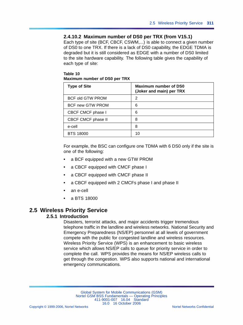
2.5 Wireless Priority Service 311
2.4.10.2 Maximum number of DS0 per TRX (from V15.1)Each type of site (BCF, CBCF, CSWM,...) is able to connect a given numberof DS0 to one TRX. If there is a lack of DS0 capability, the EDGE TDMA isdegraded but it is still considered as EDGE with a number of DS0 limitedto the site hardware capability. The following table gives the capability ofeach type of site:
Table 10Maximum number of DS0 per TRX
Type of Site Maximum number of DS0(Joker and main) per TRX
BCF old GTW PROM 2
BCF new GTW PROM 6
CBCF CMCF phase I 6
CBCF CMCF phase II 8
e-cell 8
BTS 18000 10
For example, the BSC can configure one TDMA with 6 DS0 only if the site isone of the following:
• a BCF equipped with a new GTW PROM
• a CBCF equipped with CMCF phase I
• a CBCF equipped with CMCF phase II
• a CBCF equipped with 2 CMCFs phase I and phase II
• an e-cell
• a BTS 18000
2.5 Wireless Priority Service2.5.1 Introduction
Disasters, terrorist attacks, and major accidents trigger tremendoustelephone traffic in the landline and wireless networks. National Security andEmergency Preparedness (NS/EP) personnel at all levels of governmentcompete with the public for congested landline and wireless resources.Wireless Priority Service (WPS) is an enhancement to basic wirelessservice which allows NS/EP calls to queue for priority service in order tocomplete the call. WPS provides the means for NS/EP wireless calls toget through the congestion. WPS also supports national and internationalemergency communications.
Global System for Mobile Communications (GSM)Nortel GSM BSS Fundamentals — Operating Principles
411-9001-007 16.04 Standard16.0 16 October 2006
Copyright © 1999-2006, Nortel Networks Nortel Networks Confidential
.
312 Chapter 2 GSM evolutions
2.5.2 Queuing servicesWhen a user invokes WPS and the cell has no available radio trafficchannel, the BSS queues the request according to the WPS priority level,the call initiation time, and the queuing state for the cell. Priority levels forWPS request range from level 1 (the highest priority) to level 7 (the lowestpriority). When the BSS receives a WPS assignment request message froman MSC, it determines whether a traffic channel is available and assigns theavailable channel to the WPS request.
Activation of WPS queuing management requires the following:
• The WPS request allows queuing (provides a bscQueuingOption flag)
• The BSC object allows queuing (enables the wPSManagement flag)
When a BSC object does not enable the wPSManagement flag, that objectapplies its own internal queuing priority levels for these WPS requests.When a BSC object enables the wPSManagement flag, it implements theWPS queuing management for WPS requests.
When possible, a BSS distributes WPS requests to separate queues basedon the priority level of the WPS request and several properties and prioritiesof each queue. This queue management method is faster than processingrequests only by priority level. The system processes WPS requests in thesame queue from highest priority to lowest.
2.5.3 Public access bandwidth protectionThe public access bandwidth protection feature helps to ensure that highlevels of traffic congestion and support for WPS does not prevent publicusers from accessing the network.
To implement public access bandwidth protection, a BSC designates twodifferent types of traffic channels. Although all of the channels support bothWPS calls and public calls, most of the channels support public calls witha higher priority. A smaller number of channels gives higher priority toWPS calls. The system supports fewer WPS users than public users, andtypically requires fewer resources for WPS.
As traffic channels become free, the BSC radio resource allocator appliesan algorithm to allocate channels to WPS or public calls.
2.5.4 Directed retry without queuing activation featureThis feature improves the directed retry function and applies to systemversions 14.3.1 and 15 with BSC 3000. When directed retry is enabled inthe BSS with the directed retry without queuing activation feature, both WPSand public calls are processed whether queuing is activated or not. WPSusers and public users now have directed retry processing independent ofqueuing activation, which provides a better chance to get a traffic channel.
Global System for Mobile Communications (GSM)Nortel GSM BSS Fundamentals — Operating Principles
411-9001-007 16.04 Standard16.0 16 October 2006
Copyright © 1999-2006, Nortel Networks Nortel Networks Confidential
.
2.5 Wireless Priority Service 313
2.5.5 Access class barringBecause WPS provides a priority service only to NS/EP leadership andkey personnel, the number of users is small. WPS will typically avoid asignificant impact on public use of CMRS radio capacity. During exceptionalevents, however, initial WPS requests could be so numerous that they fullyblock access to the system by public users. The Access Class Barringfeature help prevent this problem.
To avoid conflicts between WPS and public support, a BSS can dynamicallyallocate resources based on user classes, barring some access based onthe access class or classes of the associated MS. The SIM card in an MSdefines one or more access classes for the MS.
Possible access classes for an MS include the following:
• Access classes 0 through 9 are normal classes
• Access class 10 indicates whether an MS with an access class of 0-9has network access for emergency calls
• Access class 11 identifies Public Land Mobile Network (PLMN)
• Access class 12 identifies Security Services
• Access class 13 identifies Public Utilities (water, gas, electric)
• Access class 14 identifies Emergency Services
• Access class 15 identifies PLMN staff
An MS with one or more access classes of 11 through 15 cannot accessthe network for emergency calls if the BSS uses Access Call Barring toblock both access class 10 and the relevant access class (from 11 to 15) ofthe MS.
The bscMSAccessClassBarringFunction controls the Access Call Barringfeature on a BSC object and the btsMSAccessClassBarringFunctioncontrols the Access Call Barring feature on a BTS object.
During times of traffic congestion, the BSC sends Access Call Barringinformation to the BTS. When the cell is no longer congested, the BSCsends system information and returns to the BTS to deactivate AccessCall Barring.
A BSC checks for traffic congestion whenever it allocates a traffic channel.The following parameters define the level of congestion necessary to triggerAccess Call Barring:
• numberOfTCHFreeBeforeCongestion (the number of free trafficchannels in the cell)
• numberOfTCHQueuedBeforeCongestion (the number of requests fortraffic channels in all channel queues)
Global System for Mobile Communications (GSM)Nortel GSM BSS Fundamentals — Operating Principles
411-9001-007 16.04 Standard16.0 16 October 2006
Copyright © 1999-2006, Nortel Networks Nortel Networks Confidential
.
314 Chapter 2 GSM evolutions
The following parameters define the level of congestion necessary to endAccess Call Barring:
• numberOfTCHFreeToEndCongestion (the number of free trafficchannels in the cell)
• numberOfTCHQueuedToEndCongestion (the number of traffic channelrequests in all channel queues)
When traffic in a cell becomes congested, the BSC sets a supervisiontimer. Every three minutes, the BSC checks the state of the congestion andadjusts Access Call Barring as follows:
• If traffic is still congested, the system bars two more access classes(provided that they are not all barred)
• If traffic is no longer congested, the system removes the bar from two ofthe barred access classes.
When traffic in a cell is no longer congested and the system is not barringany access classes, the BSC stops the three-minute supervision timer anddiscontinues Access Call Barring.
Another mechanism, a 60-second timer, works independently of thethree-minute timer. Whereas the three-minute counter changes the numberof access classes barred, the 60-second timer changes which access levelsare barred. If Access Call Barring always blocked the same access classes(while always allowing access for other classes), it would block the samegroup of customers unfairly. By rotating the classes that it bars, Access CallBarring more evenly affects customers.
The accessClassCongestion parameter in a BTS lists all of the accessclasses which are eligible for Access Call Barring. As the 60-second timerchanges the subset of the access levels barred at different times, it onlyselects access levels that the accessClassCongestion parameter lists. Ifan access class is not in this parameter’s list, Access Call Barring will notblock it.
2.5.5.1 Performance managementIn order to monitor the access class barring feature, new counters werecreated to provide following information:
• duration access class 11 has been barred
• duration access class 12 has been barred
• duration access class 13 has been barred
• duration access class 14 has been barred
• duration access class 15 has been barred
Global System for Mobile Communications (GSM)Nortel GSM BSS Fundamentals — Operating Principles
411-9001-007 16.04 Standard16.0 16 October 2006
Copyright © 1999-2006, Nortel Networks Nortel Networks Confidential
.
2.6 GSM for Railways (GSM-R) 315
• a counter was created to monitor the number of barred access classesduring cell congestion every 1 minute (incremented at each rotationof access classes). Only access classes between [0..9] are takeninto account, since a dedicated counter exists for classes 11 to 15. Acorrelation with the number of barred access classes contained in theAccessClassCongestion parameter (removing access classes 11 to 15)gives the number of minutes a given access class (between 0 and 9) hasbeen barred. Barred Access classes of the notAllowedAccessClassesparameter are excluded from the counter triggering.
2.6 GSM for Railways (GSM-R)
CAUTIONGSM-R specificIndicates that specific equipment and specific software (such asspecific software in the BSC) dedicated to Railway application isused and that therefore the feature is not available for all standardGSM users.
2.6.1 IntroductionRailway telecommunication networks use different systems for various typesof applications and users. Most of these systems belong to a generation ofradio systems based on analog technology and different frequency rangeswith limited applications and performances.
GSM-R (GSM for Railways) is a pan-European radio system which coversthe mobile telecommunication needs of the European railways. GSM-Ruses standard GSM technology and additional features customized forrailway operations. General Packet Radio Services (GPRS) is a major partof GSM-R for data transport.
Railway operations requirements are as follows:
• A dedicated network (infrastructure, dial plan...) with specificapplications (shunting...) and operational efficiency
• Secured operations and a high reliability, especially in case ofemergency
• Group communication facilities for working teams
• Interoperability with:
— Existing railway communication infrastructures
— International railway communication networks
— Public communication networks
GSM-R is also designed to reduce operational costs.
Global System for Mobile Communications (GSM)Nortel GSM BSS Fundamentals — Operating Principles
411-9001-007 16.04 Standard16.0 16 October 2006
Copyright © 1999-2006, Nortel Networks Nortel Networks Confidential
.
316 Chapter 2 GSM evolutions
2.6.2 Advanced Speech Call Items (ASCI)Railway communication networks require specific applications to supportsafe and efficient operations. Advanced Speech Call Items (ASCI) are aset of features and functions dealing with railway operation aspects. ASCIcomes on the top of the standard GSM architecture to support all the railwayvoice and data applications.
ASCI consists of the following services:
• eMLPP (enhanced Multi-Level Precedence and Pre-emption), whichallows resource pre-emption for priority calls
• VBS (Voice Broadcast Service), which allows groups of users to receivecommon information
• VGCS (Voice Group Call Service),which allows groups of users to makecalls among groups or within a group
2.6.2.1 Enhanced Multi-Level Precedence and Pre-emption(eMLPP)By subscribing to eMLPP service, a user can explicitly or by default select apriority value when originating a call. This priority value is used within thenetwork to provide precedence to network resources, during call setup, tohigh priority calls. Moreover, a high priority call can pre-empt other outgoingcalls of lower priority in case of congestion.
eMLPP service can be provided for the following call types:
• Point to point calls:
— mobile to mobile calls
— mobile to land calls
— land to mobile calls
• VBS/VGCS calls
2.6.2.2 Voice Broadcast Service (VBS)VBS is, for speech calls only, allows a user to broadcast a speech call toa pre-defined set of destination subscribers in a pre-defined geographicalbroadcast area.
The set of destination subscribers is identified by a Group Id. Mobiledestination subscribers are only involved in the call while they are locatedwithin the broadcast area, unless they have been marked as dispatchers.Fixed-line destination subscribers and mobile subscribers marked asdispatchers may be located anywhere. The information about registereddestination subscribers, dispatchers and broadcast areas is, for each GroupId, stored in the Group Call Register (GCR).
Global System for Mobile Communications (GSM)Nortel GSM BSS Fundamentals — Operating Principles
411-9001-007 16.04 Standard16.0 16 October 2006
Copyright © 1999-2006, Nortel Networks Nortel Networks Confidential
.
2.6 GSM for Railways (GSM-R) 317
A VBS call can be established by either a service subscriber or by adispatcher, while the call can be terminated by either the calling subscriberor any nominated dispatcher. Other service subscribers can not terminate aVBS call. They have listening capabilities only.
A standard full duplex channel is provided to the calling subscriberand dispatchers, while simplex down-link channels are allocated to alldestination service subscribers, with one common down-link per cell ofthe broadcast area.
2.6.2.3 Voice Group Call Service (VGCS)VGCS is for speech calls only and has standardized on the basis ofVBS. VGCS allows speech conversations between a pre-defined set ofdestination subscribers in a pre-defined geographical Group Call Area.
The set of destination subscribers is identified by a Group Id. In general,mobile served subscribers will only be involved in the call while they arelocated within the Group Call Area. Fixed-line destination subscribers andfixed-line or mobile subscribers marked as dispatchers may be locatedwithin or outside the Group Call Area. The information about registereddispatchers, destination subscribers and Group Call Area is, for each GroupId, stored in the Group Call Register (GCR).
A VGCS call can be established by either a service subscriber or by adispatcher. The call can be terminated by either the calling subscriberor any nominated dispatcher, using an operator determined DTMF tonesequence or by detecting silence on the voice channel. A standard fullduplex channel is provided to dispatchers and to the calling subscriberduring the call setup. Simplex down-link channels are initially allocated toall destination service subscribers, with one common down-link per cell ofthe VGCS Group Call Area.
Once the call has been setup, dispatchers (both mobile and fixed) keep the2-way speech connection. Mobile call originators may release their uplink toallow other mobile users to talk. Once the up-link has been released, thecalling subscriber and other mobile users may talk only after requestingthe up-link. Only one up-link is available for each group, regardless ofgroup area size. Dispatchers are allowed to talk anytime, and their voice isbroadcasted to all members. When call originators and mobile destinationsubscribers who are not dispatchers move out of the group area their call isdropped. Their call is resumed when they move back into the group area.
2.6.2.4 ASCI feature interworkingWPS features (for a description, refer to Section 2.5 "Wireless PriorityService" (page 311)) are not impacted by ASCI calls (either VBS or VGCS).
Global System for Mobile Communications (GSM)Nortel GSM BSS Fundamentals — Operating Principles
411-9001-007 16.04 Standard16.0 16 October 2006
Copyright © 1999-2006, Nortel Networks Nortel Networks Confidential
.
318 Chapter 2 GSM evolutions
If WPS features are activated, they have an impact on the way TCHs areallocated to incoming requests. This impact on TCH allocation has animpact of the way ASCI calls are established.
ASCI calls and WPS calls are mainly managed inside the BSS based onthe priority of the call.
Pre-emption, which is used in GSM-R, is not authorized for WPS.
2.6.3 Activation of GSM-R featuresIn order to the activate GSM-R features, the Asci_Mode parameter has tobe set to Enabled in the omc_services.cfg file at the OMC-R. Hence, theASCI related parameters become available at the OMC-R.
2.6.4 Hardware constraintsASCI features are only guaranteed on BSC 12000HC of type 12000 and onBSC 3000.
ASCI features are only guaranteed on a BTS with CBCF, New Design DRX,DRX ND3 and eDRX, independently of the frequency band.
DCU2, DCU4, DRX EGAL 1 and DRX EGAL 2 do not support ASCI features.
2.6.5 Features implementedThe following features were introduced in V15.1R release.
2.6.5.1 MS late entryThis feature allows an MS, which is moving to a cell where a railwayemergency call is ongoing, to be periodically notified of this ongoingemergency call even if the MS is already involved in another call.
Two parameters, emergencyThreshold and timerGcchNotif, are providedto implement this feature. Refer to these entries in NTP <124> for moreinformation.
2.6.5.2 Uplink reply and notification responseThis mechanism applies to VBS and VGCS calls. It aims at optimizing theuse of radio resources.
Upon request of the network, MSs which have listening capabilities of anongoing group call, have to report their presence. If no report is receivedfrom a cell, the traffic channel of the group call is released in this cell.Only a notification that a group call is ongoing is broadcasted on thenotification channel. If then an MS roams to such a cell and sends a request(notification response), a traffic channel is established for the group call.
Global System for Mobile Communications (GSM)Nortel GSM BSS Fundamentals — Operating Principles
411-9001-007 16.04 Standard16.0 16 October 2006
Copyright © 1999-2006, Nortel Networks Nortel Networks Confidential
.
2.6 GSM for Railways (GSM-R) 319
Two parameters, uplinkReply and uplinkReplyTimer, are provided toimplement this feature. Refer to these entries in NTP <124> for moreinformation.
2.6.5.3 VGCS uplink release managementThe VGCS signalling between BSS and NSS has been modified so that it isnow compliant with the 3GPP specifications. The Nortel Networks BSS canthen better interface with another vendor NSS.
2.6.5.4 ASCI/GPRS support in one cellGPRS communications can be established in a cell where ASCI calls areongoing. Similarly, ASCI calls can be established in a cell where GPRScommunications are ongoing. There is no interaction between ASCI andGPRS calls (no notifications).
Note that the radioAllocator parameter must then be set to "voice + dataCircuit + packetData". Refer to this entry in NTP <124> for moreinformation.
2.6.5.5 OTDI Immediate Setup 2This feature allows the setup message to carry Originator To DispatcherInformation (OTDI) in case of emergency. This information includesthe Functional Number (FN) of the originator. A group call can then beimmediately setup using Immediate Setup 2 procedure.
2.6.5.6 Mobility class sensitivity countersA GSM-R network handles various types of application, which requiredifferent levels of Quality of Service (QoS). The radio design of the TrainControl Applications is based on 8-watt MSs, which require a high levelQoS. The radio design of the Shunting Applications is based on 2-wattMSs, which require lower QoS.
It is then important that observation counters distinguish between 8-wattMS events and 2-watt MS events. The msPowerClassToggle parameter isprovided for that purpose. Moreover, dedicated counters trace 8-watt MSevents regardless of msPowerClassToggle parameter value.
For more information on msPowerClassToggle, refer to NTP <124>. Formore information on counters, refer to NTP <125>.
Global System for Mobile Communications (GSM)Nortel GSM BSS Fundamentals — Operating Principles
411-9001-007 16.04 Standard16.0 16 October 2006
Copyright © 1999-2006, Nortel Networks Nortel Networks Confidential
.
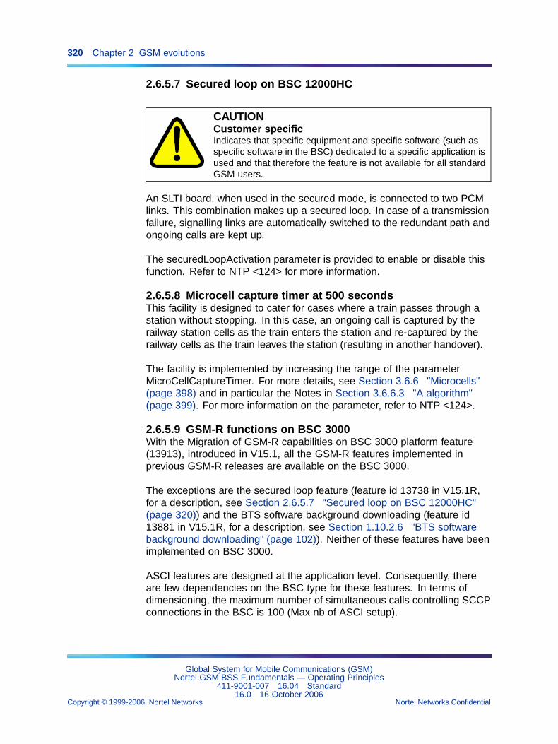
320 Chapter 2 GSM evolutions
2.6.5.7 Secured loop on BSC 12000HC
CAUTIONCustomer specificIndicates that specific equipment and specific software (such asspecific software in the BSC) dedicated to a specific application isused and that therefore the feature is not available for all standardGSM users.
An SLTI board, when used in the secured mode, is connected to two PCMlinks. This combination makes up a secured loop. In case of a transmissionfailure, signalling links are automatically switched to the redundant path andongoing calls are kept up.
The securedLoopActivation parameter is provided to enable or disable thisfunction. Refer to NTP <124> for more information.
2.6.5.8 Microcell capture timer at 500 secondsThis facility is designed to cater for cases where a train passes through astation without stopping. In this case, an ongoing call is captured by therailway station cells as the train enters the station and re-captured by therailway cells as the train leaves the station (resulting in another handover).
The facility is implemented by increasing the range of the parameterMicroCellCaptureTimer. For more details, see Section 3.6.6 "Microcells"(page 398) and in particular the Notes in Section 3.6.6.3 "A algorithm"(page 399). For more information on the parameter, refer to NTP <124>.
2.6.5.9 GSM-R functions on BSC 3000With the Migration of GSM-R capabilities on BSC 3000 platform feature(13913), introduced in V15.1, all the GSM-R features implemented inprevious GSM-R releases are available on the BSC 3000.
The exceptions are the secured loop feature (feature id 13738 in V15.1R,for a description, see Section 2.6.5.7 "Secured loop on BSC 12000HC"(page 320)) and the BTS software background downloading (feature id13881 in V15.1R, for a description, see Section 1.10.2.6 "BTS softwarebackground downloading" (page 102)). Neither of these features have beenimplemented on BSC 3000.
ASCI features are designed at the application level. Consequently, thereare few dependencies on the BSC type for these features. In terms ofdimensioning, the maximum number of simultaneous calls controlling SCCPconnections in the BSC is 100 (Max nb of ASCI setup).
Global System for Mobile Communications (GSM)Nortel GSM BSS Fundamentals — Operating Principles
411-9001-007 16.04 Standard16.0 16 October 2006
Copyright © 1999-2006, Nortel Networks Nortel Networks Confidential
.
2.6 GSM for Railways (GSM-R) 321
2.6.6 Channel Release on BTS after Abis failureIf an MS is connected to a BTS and an Abis link or a BSC failure occurs, thedata communications remains ongoing on the cell at the BTS side whereasthe communications are released on the BSC/MSC side.
For voice calls, the user will detect that the speech path is lost and willtake down the call. For data communication, the MS will remained parkedon the cell until the application realizes that no data is going through andtakes down the call.
Without this feature, 30 seconds after the Abis PCM failure (or BSC failure)detection, the BTS sets in the system information broadcast on BCCHto the MS that the cell is “barred”. However, this barring does not dropongoing calls in this cell, and it does not prevent a handover to this cell.Voice and data communications remain ongoing on the cell and the MSbecause the BTS keeps broadcasting BCCH and SACCH, even though thecommunications are released on the BSC/MSC side. As long as the BTScontinues to broadcast, another MS can select the cell.
With this feature, if an Abis PCM failure (or a BSC failure) is detected bythe TRXs of the BTS, the transmission is turned off and this stops thebroadcasting of BCCH and SACCH. When the TRXs of the BTS detect thatthe Abis PCM (or BSC) has come back, the power amplifiers are turnedon again. Ongoing calls are dropped thanks to MS radio link time outalgorythm, and no MS can select this cell for a handover or to camp on it.
Since turning the PA off will affect its MTBF, it is preferable to turn off thetransmission instead of the PA so that its life is not affected.
Global System for Mobile Communications (GSM)Nortel GSM BSS Fundamentals — Operating Principles
411-9001-007 16.04 Standard16.0 16 October 2006
Copyright © 1999-2006, Nortel Networks Nortel Networks Confidential
.
322 Chapter 2 GSM evolutions
Global System for Mobile Communications (GSM)Nortel GSM BSS Fundamentals — Operating Principles
411-9001-007 16.04 Standard16.0 16 October 2006
Copyright © 1999-2006, Nortel Networks Nortel Networks Confidential
.
323
Chapter 3Radio configuration principles
3.1 IntroductionA Base Station Subsystem includes a Base Station Controller (BSC) thatmanages Base Transceiver Stations (BTSs) and is linked to TransCodingUnits (TCUs) and a Packet Control Unit Support Node (PCUSN).
The Dictionary of objects (see Section 3.2 "Dictionary of objects" (page324)) describes the physical and logical objects that make up a digitalmobile network under OMC-R management control, and the objects thatdescribe the OMC-R functions. Section 3.3 "Radio entity managementprinciples" (page 339) introduces some principles to help users managenetwork entities.
The BSS main radio configuration principles are described under thefollowing headings:
• radio measurement processing (see Section 3.4 "Radio measurementprocessing" (page 355))
• cell selection and reselection (see Section 3.5 "Radio cell selectionand reselection" (page 367))
• handover management (see Section 3.6 "Handover management"(page 372))
• power control (see Section 3.7 "Power control" (page 399))
• call monitoring (see Section 3.8 "Call monitoring" (page 415))
• radio resource allocation (see Section 3.9 "Radio resource allocation"(page 418))
• frequency hopping management (see Section 3.10 "Frequency hoppingmanagement" (page 421))
• defense and reconfiguration (see Section 3.12 "Defense andreconfiguration" (page 424))
Global System for Mobile Communications (GSM)Nortel GSM BSS Fundamentals — Operating Principles
411-9001-007 16.04 Standard16.0 16 October 2006
Copyright © 1999-2006, Nortel Networks Nortel Networks Confidential
.
324 Chapter 3 Radio configuration principles
3.2 Dictionary of objects3.2.1 The omc object
The omc object describes the OMC-R manager that controls the exchangeswith the users on the Man-Machine interface and the OMC-R agent onthe Q3 interface.
This non Q3, MMI object allows users to manage the active alarm criteriaconfiguration and do the following:
• shut down the applications in a workstation, the active server, or allmachines
• consult OMC-R manager server software application markers (eachapplication is marked with a name and a version number)
• consult workstation software application markers (each application ismarked with a name and a version number)
• manage the EFTs (or delivery) containing BSS software at manager level
• archive/restore operating data and files such as job results, systemsession log, and inter-user mail, and manage archiving cartridges
• consult OMC-R manager observation reports
The omc object is unique on the OMC-R. It is created by the system andcannot be deleted.
3.2.2 The md subtreeThe md subtree includes the following objects:
• md
• bscMdInterface
• mdScanner
• traceControl
• executableSoftware
• callPathTrace
• mdWarning
• log
• record-type objects
• efd
3.2.2.1 The md objectThe md object describes the OMC-R agent that provides mediationfunctions and manages the exchanges with the BSSs on the OMN interface.
Global System for Mobile Communications (GSM)Nortel GSM BSS Fundamentals — Operating Principles
411-9001-007 16.04 Standard16.0 16 October 2006
Copyright © 1999-2006, Nortel Networks Nortel Networks Confidential
.
3.2 Dictionary of objects 325
The md object defines the OMC-R agent hardware configuration. It allowsusers to manage the system date and time parameters and do the following:
• switch over the operations to the backup server
• restart the active server
• consult the OMC-R agent software application markers
• manage the EFTs containing BSS software at agent level
• archive/restore operating data and files and manage archiving cartridges
• consult OMC-R agent observation reports
The md object is unique on the OMC-R. It is created by the system andcannot be deleted.
3.2.2.2 The bscMdInterface objectThe bscMdInterface object class describes the BSS/OMC-R links, that isthe transport connections used for BSS/OMC-R exchanges on the OMNinterface ( X.25 links on BSC 12000HC / Ethernet link on BSC 3000 andaccess ports on OMC-R).
• All the transport connections between a BSS and the OMC-R arecarried by one, dedicated protocol support link. The link is enabledwhen the object is created.
• BSS access points are identified by two X.25 addresses; one is thepreferred address and the other is the backup address. The OMC-Rselects one of these addresses and enters the associated transportselector (preferred or backup).
• The OMC-R access point is identified by the logical number of theOMC-R agent port. It is selected by the OMC-R agent if not definedby the user.
The bscMdInterface objects allow users to manage BSC circular files inwhich unsolicited messages are stored. The possible actions are open,close, display state, and purge. The following types of circular files aredefined:
• INIT ............. initialization
• MAJOR FAULT .... major faults
• MINOR FAULT .... minor faults
• PERF ............. permanent and temporary observation data
• INST PANEL ...... instrument panel observation data
• TRACE ........... call tracing and call path tracing data
• MARK ............ markers
Global System for Mobile Communications (GSM)Nortel GSM BSS Fundamentals — Operating Principles
411-9001-007 16.04 Standard16.0 16 October 2006
Copyright © 1999-2006, Nortel Networks Nortel Networks Confidential
.
326 Chapter 3 Radio configuration principles
• TRANSAC ........ BSS/OMC-R transactions (TGE-RGE)
• UPDATE .......... on-line build operation
Circular files are automatically created by the system and cannot be deleted.The following apply:
• INIT and FAULT files are created with the BSC.
• PERF, INST PANEL, TRACE, MARK, and TRANSAC files are createdwhen the BSC application database is built.
• INIT, MARK, and TRANSAC files are not managed by users.
3.2.2.3 The mdScanner objectThe mdScanner object class describes all the observations handled by theOMC-R agent Performance Management function, which are as follows:
• permanent general md observation
• permanent general bsc observation
• general statistic observation - OGS
• fast statistic observation - OFS
• real time observation - ORT
• diagnostic observation - ODIAG
• temporary Signalling Link observation
• temporary Abis Interface Bts observation
• temporary pcmCircuit observation
• temporary handover observation
3.2.2.4 The bscCounterList objectThe bscCounterList object class describes the lists of counters a givenV11+ BSC collects for an observation type.
The four bscCounterList objects (one for OGS, one for OFS, one for ORT,and one for ODIAG) must be defined at BSC creation but in a "no build"state. These object instances are necessary for the operation "Build BDA"of the BSC.
3.2.2.5 The traceControl objectThe traceControl object class describes the BSS Call tracing functionwhich is controlled by the MSC.
Global System for Mobile Communications (GSM)Nortel GSM BSS Fundamentals — Operating Principles
411-9001-007 16.04 Standard16.0 16 October 2006
Copyright © 1999-2006, Nortel Networks Nortel Networks Confidential
.
3.2 Dictionary of objects 327
3.2.2.6 The executableSoftware objectThe executableSoftware object describes a collection of files which aredownloaded between the OMC-R and the BSC 3000. The role of theexecutableSoftware object is to send a software package to the BSC 3000.
3.2.2.7 The callPathTrace objectThe callPathTrace object class describes the BSS Call path tracingfunction, meaning the follow-up of calls using one or more radio resourcesof a given type in the BSS (cells, TRX/DRXs, or terrestrial circuits).
All calls using the selected resources are monitored, provided the maximumnumber of observations authorized for each type of data collected (basic,handover, or radio) is not reached.
3.2.2.8 The mdWarning objectThe mdWarning object class describes the conditions in which notificationsrelated to "observation counter threshold crossing" and "excessive softwareapplication error rate" are processed by the OMC-R agent and the relatedalarms are triggered.
3.2.2.9 The log objectThe log object class describes the logs used to store fault, observation, andtrace messages on the OMC-R agent disks.
• The current alarm log is no.1.
The records of the current alarm log are represented by alarmRecordand stateChangeRecord objects.
• A current observation log is associated with each created mdScannerobject that describes a permanent or temporary observation (instrumentpanel observation data are not stored).
The records of a current permanent observation log are represented byobservationFileReadyRecord objects.
The records of a current temporary observation log are represented bymdScanReportRecord objects.
• A current trace log is associated with each created traceControl orcallPathTrace object that describes a BSS Call tracing or Call pathtracing function.
The records of a current trace log associated with a traceControl objectare represented by traceFileReadyRecord and tracelogRecordobjects.
The records of a current trace log associated with a callPathTrace objectare represented by traceFileReadyRecord objects.
Global System for Mobile Communications (GSM)Nortel GSM BSS Fundamentals — Operating Principles
411-9001-007 16.04 Standard16.0 16 October 2006
Copyright © 1999-2006, Nortel Networks Nortel Networks Confidential
.
328 Chapter 3 Radio configuration principles
• A restored log is created whenever fault, observation, or trace data arerestored to the OMC-R agent disks.
The OMC-R agent creates and manages log objects. A current or restoredlog is automatically deleted when the storage time defined in staticconfiguration data expires.
3.2.2.10 The record-type objectsThe alarmRecord object class describes the logged information that resultsfrom alarm notifications.
The stateChangeRecord object class describes the logged information thatresults from state change notifications.
The observationFileReadyRecord object class describes the format ofpermanent observation data recorded in an observation log.
The mdScanReportRecord object class describes the format of temporaryobservation data recorded in an observation log.
The traceLogRecord object class describes the format of call tracing datarecorded in a trace log for the priority traces collected by the Call tracingfunction.
The traceFileReadyRecord object class describes the names of the fileswhere non priority traces collected by the Call tracing and Call path tracingfunctions are recorded.
The OMC-R agent creates and manages record-type objects.
3.2.2.11 The efd objectThe efd object class describes the conditions in which observation andtrace messages are fed back to the OMC-R manager.
If the administrativeState of an efd object is "unlocked", the OMC-R agentfeeds back the messages handled by the object to the OMC-R manager. Ifnot, the messages are not forwarded.
3.2.3 The network subtreeThe network subtree includes the following objects:
• network
• bsc subtree objects
3.2.3.1 The network objectThe network object gathers the overall BSSs defined in the OMC-R. It isthe root of the bsc subtree described hereafter.
Global System for Mobile Communications (GSM)Nortel GSM BSS Fundamentals — Operating Principles
411-9001-007 16.04 Standard16.0 16 October 2006
Copyright © 1999-2006, Nortel Networks Nortel Networks Confidential
.
3.2 Dictionary of objects 329
This object allows users to run multiple-type commands (scope & filter) ona set of BSSs, such as List, Set, Get, and Delete. These commands areaccessed as options of the Several submenu of the Objects menu in an"OMC-R Browser" window.
The network object is unique on the OMC-R agent. It is created by thesystem and cannot be deleted.
3.2.4 The bsc subtreeThe Base Station Controller (BSC) is the core of the BSS configuration. ABSC is solely identified on the OMC-R, and all the objects describing a BSSare defined in relation to the bsc object.
A BSC communicates with the MSC (via the TCUs) through the A interface,with the TCUs through the Ater interface, and with the BTSs through theAbis interface.
The bsc subtree includes the following objects:
• bsc
• pcu
• signallingPoint
• signallingLinkSet
• pcmCircuit
• lapdLink
• bscCounterList
• transcoder subtree objects
• btsSiteManager subtree objects
3.2.4.1 The bsc objectThe bsc object class describes the BSCs and their hardware configuration(architecture and type).
Specific actions on the bsc objects allow to do the following:
• manage the BSC operations such as BSC processing chain reset thatmay trigger restart
• control the operations such as manage BSC application database BDA(build, on-line reset, or off-line reset), and check BDA and OMC-R agentoperations database (BDE) consistency
• monitor BSC control unit and equipment operations
• synchronize the operations to provide equipment management bychecking BSS date and time consistency with the system references,broadcasting the reference date and time to the BSCs
Global System for Mobile Communications (GSM)Nortel GSM BSS Fundamentals — Operating Principles
411-9001-007 16.04 Standard16.0 16 October 2006
Copyright © 1999-2006, Nortel Networks Nortel Networks Confidential
.
330 Chapter 3 Radio configuration principles
BSCs are driven by software.
3.2.4.2 The signallingPoint and signallingLinkSet objectsThe signallingPoint object class describes the BSC-MSC links on BSCend.
The signallingLinkSet object class describes BSC-MSC links on MSC end.
There is one SS7 signalling link set per BSC. A (signallingPoint,signallingLinkSet) combination identifies the set on the OMC-R.
3.2.4.3 The signallingLink objectThe signallingLink object class describes the SS7 signalling links usedon the A interface for BSC-MSC call processing exchanges such as callestablishment, release of resources, etc.
The SS7 links are carried out by the TCUs. Each link occupies one timeslot at 64 kbps on an A interface PCM link and one time slot at 64 kbps onan Ater interface PCM link.
A special action on signallingLink objects allows users to inhibit the SS7links.
3.2.4.4 The pcmCircuit object (Abis, Ater and Agprs interfaces)The pcmCircuit object class describes the external BSC PCM links onthe Abis (BSC-BTS connections), Ater (BSC-TCU connections) and Agprs(BSC-PCUSN connections) interfaces.
3.2.4.5 The xtp objectThe xtp object class (eXchange Termination Point) describes the terrestrialtraffic circuits used on the A interface for BSC-MSC voice call and dataprocessing exchanges.
The terrestrial traffic circuits are carried out by the TCUs. Each circuitoccupies one time slot at 64 kbps on an A interface PCM link and one timeslot at 16 kbps on an Ater interface PCM link.
3.2.4.6 The lapdLink objectThe lapdLink object class describes the Level 3 links that support LAPDsignalling between the BSCs and the following radio entities:
• radio site BCF and TRX/DRXs on the Abis interface
• remote transcoders on the Ater interface
3.2.4.7 The bsc 2G objectThe bsc 2G object describes the managed object class representing asecond generation BSC hardware.
Global System for Mobile Communications (GSM)Nortel GSM BSS Fundamentals — Operating Principles
411-9001-007 16.04 Standard16.0 16 October 2006
Copyright © 1999-2006, Nortel Networks Nortel Networks Confidential
.
3.2 Dictionary of objects 331
3.2.4.8 The bsc e3 objectThe bsc e3 object describes the managed object class representing a thirdgeneration BSC equipment
3.2.4.9 The bscCounterList objectThe bscCounterList object class describes the lists of counters a givenV11+ BSC collects for an observation type.
The four bscCounterList objects (one for OGS, one for OFS, one for ORT,and one for ODIAG) must be defined at BSC creation but in a "no build"state. These object instances are necessary for the operation "Build BDA"of the BSC.
The maximum number of observation counters is the result of a formula. Forits description, refer to the "Build BDA" action of bsc object in NTP <128>.
ORT counters cannot be dynamically configured.
3.2.5 The transcoder subtreeThe remote transcoding units (TCUs) installed on the MSC site are used tominimize Abis and Ater interface PCM link needs.
The TCUs communicate with the BSC through the Ater interface and withthe MSC through the A interface.
The transcoder subtree includes the following objects:
• transcoder
• pcmCircuit (A)
• transcoderBoard
• tcu
• tcu e3
3.2.5.1 The transcoder objectThe transcoder object class describes the remote transcoding units thathandle the information conveyed on PCM links between the BSC and theMSC.
A TCU controls one PCM link with the BSC and four links with the MSC.A TCU communicates with the BSC across an LAPD signalling link and isidentified by a TEI address.
3.2.5.2 The pcmCircuit object (A interface)The pcmCircuit object class describes the external TCU PCM links on theA interface (TCU-MSC connections).
Global System for Mobile Communications (GSM)Nortel GSM BSS Fundamentals — Operating Principles
411-9001-007 16.04 Standard16.0 16 October 2006
Copyright © 1999-2006, Nortel Networks Nortel Networks Confidential
.
332 Chapter 3 Radio configuration principles
3.2.5.3 The transcoderBoard objectThe transcoderBoard object class describes the transcoder boards(TCBs) equipping the TCU 2G which handle the rate conversions betweendata conveyed on the Ater interface PCM links (BSC 12000HC-TCU 2Gexchanges) and data conveyed on the A interface PCM links (TCU 2G-MSCexchanges).
TCBs are driven by software.
3.2.5.4 The tcu objectThe tcu object describes the tdti board which handles the PCM links onthe Ater interface (BSC-TCU2G exchanges) and on the A interface (TCU2G-MSC exchanges).
3.2.5.5 The tcu e3 objectThe tcu e3 object describes the equipment of TCU 3000 which handles theconversion rates between data conveyed on the Ater interface PCM links(BSC 3000-TCU 3000 exchanges) and data conveyed on the A interfacePCM links (TCU 3000-MSC exchanges).
The tcu e3 objects are driven by tcu e3 software.
3.2.6 The btsSiteManager subtreeThe Base Transceiver Stations (BTSs) handle radio transmissions.
A BTS communicates with the BSC through the Abis interface and with themobiles through the Radio interface.
The Radio interface is characterized by geographic space divisions (cellcoverage), time divisions (TDMA), and frequency divisions (mobile networkfrequency band).
The btsSiteManager subtree includes the following objects:
• btsSiteManager
• bts and functional associated objects
• transceiverEquipment
• transceiver
• channel
3.2.6.1 The btsSiteManager objectThe btsSiteManager object class describes the radio equipment (BTSs)controlled by the BSC.
A radio site covers one or more cells. A BTS manages a synchronous setof cells.
Global System for Mobile Communications (GSM)Nortel GSM BSS Fundamentals — Operating Principles
411-9001-007 16.04 Standard16.0 16 October 2006
Copyright © 1999-2006, Nortel Networks Nortel Networks Confidential
.
3.2 Dictionary of objects 333
Actions on btsSiteManager objects include querying the hardwareconfiguration of a BTS, querying the data configuration of a radio site,querying information on battery (voltage value, malfunctions...), and forcinga BTS to use its battery.
Radio site BCFs are driven by software.
3.2.6.2 The bts object and the functional associated objectsThe bts object The bts object class describes the serving radio cells.
A radio cell is a geographic area covered by synchronous radio equipment(same GSM reference time).
The different types of cells are normal, micro, and umbrella. The cells canbe concentric and work in normal (35-km coverage) or extended (120-kmcoverage) mode.
Actions on bts objects include controlling short message broadcasts inunacknowledged mode and forcing handovers towards the neighbor cells.
The bts-related functional objects are as follows:
• adjacentCellHandOver
• adjacentCellReselection
• frequencyHoppingSystem
• handoverControl
• powerControl
• transceiverZone (concentric cells)
The adjacentCellHandOver object The adjacentCellHandOver objectclass describes the neighbor cells of the serving cells for handovermanagement in a BSS.
At least one object must be associated with each bts object created on theOMC-R in order to authorize handovers in the network serving cells.
The number of created instances per serving cell is limited to 32.
The adjacentCellReselection object The adjacentCellReselectionobject class describes the cells used by the serving cells for reselectionmanagement in a BSS.
At least one object must be associated with each bts object created on theOMC-R in order to authorize reselections in the network serving cells.
The number of created instances per serving cell is limited to 32.
Global System for Mobile Communications (GSM)Nortel GSM BSS Fundamentals — Operating Principles
411-9001-007 16.04 Standard16.0 16 October 2006
Copyright © 1999-2006, Nortel Networks Nortel Networks Confidential
.
334 Chapter 3 Radio configuration principles
The frequencyHoppingSystem object The frequencyHoppingSystemobject class describes the sets of frequency channels that can be allotted tothe radio time slots (TSs) of the serving cell TDMA frames.
These objects are not created from a bts object unless frequency hoppingis enabled in the cell. They are referenced by the channel objects thatdescribe the radio time slots in the TDMA frames related to cells wherefrequency hopping is allowed.
The number of created instances per serving cell is limited to 64.
The handOverControl object The handOverControl object classdefines the handover management parameters in serving cells.
A handOverControl object must be created for each bts object created onthe OMC-R. This object is unique for a given bts object.
Handover management parameters include the following: enablingconditions, level and quality thresholds, average distance computingparameters, level, quality, interference, and corrective factors used formissing measurements.
The powerControl object The powerControl object class defines thepower control management parameters in serving cells.
A powerControl object must be created for each bts object created on theOMC-R. This object is unique for a given bts object.
Power control management parameters include the following: enablingconditions, power control algorithm selection, maximum authorizedpower, signal reception level and quality, starting conditions, and mobiletransmission power steps.
The transceiverZone object The transceiverZone object classdescribes the TDMA frame distribution in concentric cells.
Two transceiverZone objects must be created for each bts object describinga concentric cell on the OMC-R. One of the objects describes the outer orlarge zone, the other one describes the inner or small zone.
The transceiverZone objects are referenced by the transceiver objects thatdescribe the TDMA frames used by concentric cells.
A transceiverZone object must also be created in mono-zone ornon-concentric cells due to mediation reasons.
Global System for Mobile Communications (GSM)Nortel GSM BSS Fundamentals — Operating Principles
411-9001-007 16.04 Standard16.0 16 October 2006
Copyright © 1999-2006, Nortel Networks Nortel Networks Confidential
.
3.2 Dictionary of objects 335
3.2.6.3 The transceiverEquipment objectThe transceiverEquipment object class describes the radio transceivers(TRXs or DRXs) that handle TDMA frames in the BTSs.
A TRX is a logical entity that regroups the following physical entities: a radiotransmitter (TX), a TDMA frame processor (FP), and a radio receiver (RX).Each RX is partnered with one FP to create a FPRX entity.
A DRX is a physical entity that handles the same three functions.
The TRX/DRXs communicate with the BSC across LAPD signalling linksand are identified by a TEI address.
The TEI addresses of the TRX/DRXs must be allocated in logical ascendingorder (see NTP < 124 >).
A special action on transceiverEquipment objects allows users to queryTRX/DRX hardware configuration.
TRX/DRXs are driven by software.
3.2.6.4 The transceiver objectThe transceiver object class describes the TDMA radio transmission carrierframes (logical transmitters).
At any given time, a TDMA frame is partnered with one, and only one,TRX/DRX. The BSC dynamically decides the TDMA-TRX/DRX associations.
A transceiver object has no administrativeState of its own. ItsoperationalState depends on the administrativeState of the parent btsobject.
3.2.6.5 The channel objectThe channel object class describes the radio time slots of the TDMAtransmission frames. Each TDMA frame carries eight physical channels.
If frequency hopping is not allowed in a cell, all the time slots (TSs) in theTDMA frames related to the cell use the same time frequency channeldefined by the user.
If frequency hopping is allowed in the cell and a radio time slot, the TSuses a specific radio frequency channel at a given time selected from themobileAllocation list defined by the frequencyHoppingSystem objectreferenced by the channel object (fhsRef attribute) and dependent on thebts object describing the covering cell.
Global System for Mobile Communications (GSM)Nortel GSM BSS Fundamentals — Operating Principles
411-9001-007 16.04 Standard16.0 16 October 2006
Copyright © 1999-2006, Nortel Networks Nortel Networks Confidential
.
336 Chapter 3 Radio configuration principles
A time slot in the same TDMA frame may not be allowed to frequency hop(it uses the frequency channel allocated by the user), or can obey frequencyhopping laws.
The BCCH in a cell is automatically assigned the bCCHFrequencyallocated to the cell by the user. If the frequency is changed by the user,the radio time slot is appropriately reconfigured.
3.2.7 The multiple site objectThe Base Transceiver Stations (BTSs) controlled by a BSC may be chained(drop & insert connections) on a radio site and share the same Abis PCMresources.
The multiple site object class describes such BTS chains in the BSSs.
The btsSiteManager objects that describe the BTSs in a chain must beentered in the order of physical chaining, beginning with the BTS closestto the BSC.
The multiple site objects are non-Q3, MMI objects that are locally managedby the OMC-R manager. They are unknown to the OMC-R agent and arenot stored in its operations database (BDE).
3.2.8 The software objectThe software object class describes the software versions of the BSSentities driven by software, saved on BSC disks.
A software object must be created for every bsc, btsSiteManager,transceiverEquipment, and transcoderBoard object created on the OMC-R.This object is unique for a given managed object.
The software objects are locally managed in the OMC-R (no information isrecorded in the BSC application databases).
Actions on the software object allow users to do the following:
• download BSS software in the BSC
• start up new BSS software versions
• consult BSS software application markers
3.2.9 The short message objectThe short message object class describes the short messages created byusers for unacknowledged broadcast to mobiles not engaged in calls.
Only a limited number of short messages can be broadcast in a radio cellat a time.
Global System for Mobile Communications (GSM)Nortel GSM BSS Fundamentals — Operating Principles
411-9001-007 16.04 Standard16.0 16 October 2006
Copyright © 1999-2006, Nortel Networks Nortel Networks Confidential
.
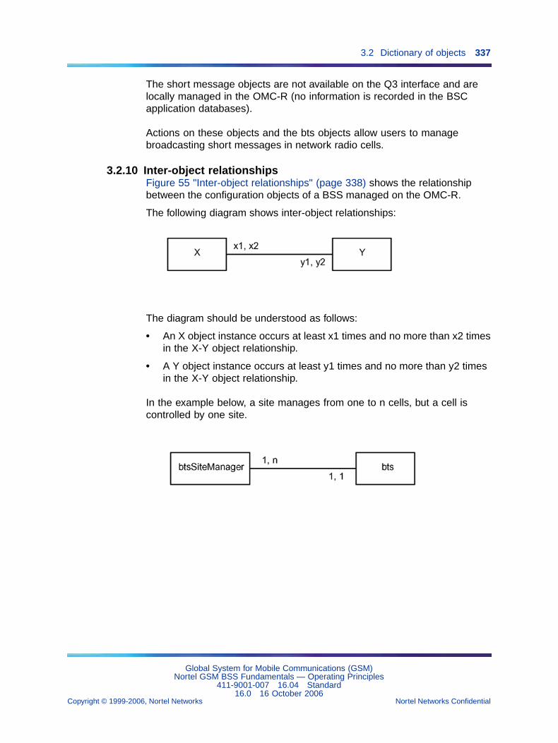
3.2 Dictionary of objects 337
The short message objects are not available on the Q3 interface and arelocally managed in the OMC-R (no information is recorded in the BSCapplication databases).
Actions on these objects and the bts objects allow users to managebroadcasting short messages in network radio cells.
3.2.10 Inter-object relationshipsFigure 55 "Inter-object relationships" (page 338) shows the relationshipbetween the configuration objects of a BSS managed on the OMC-R.
The following diagram shows inter-object relationships:
The diagram should be understood as follows:
• An X object instance occurs at least x1 times and no more than x2 timesin the X-Y object relationship.
• A Y object instance occurs at least y1 times and no more than y2 timesin the X-Y object relationship.
In the example below, a site manages from one to n cells, but a cell iscontrolled by one site.
Global System for Mobile Communications (GSM)Nortel GSM BSS Fundamentals — Operating Principles
411-9001-007 16.04 Standard16.0 16 October 2006
Copyright © 1999-2006, Nortel Networks Nortel Networks Confidential
.
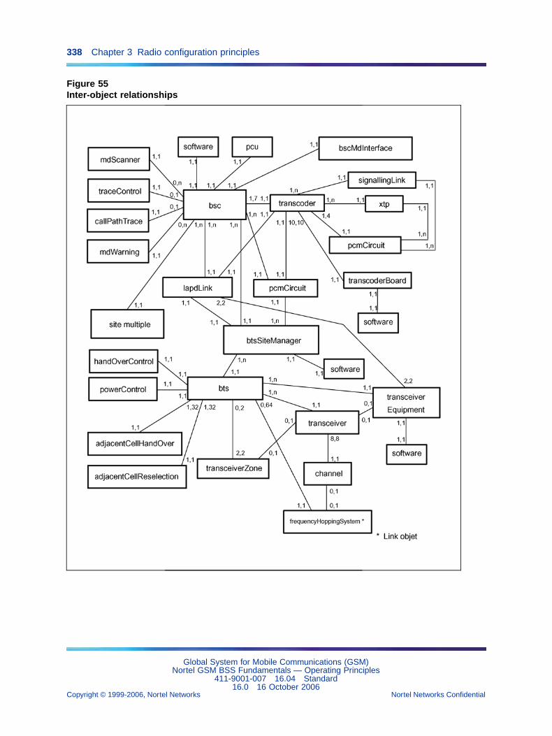
338 Chapter 3 Radio configuration principles
Figure 55Inter-object relationships
Global System for Mobile Communications (GSM)Nortel GSM BSS Fundamentals — Operating Principles
411-9001-007 16.04 Standard16.0 16 October 2006
Copyright © 1999-2006, Nortel Networks Nortel Networks Confidential
.
3.3 Radio entity management principles 339
3.3 Radio entity management principles3.3.1 BSC management
3.3.1.1 BSC application database managementThe following actions are performed on a BSC application database:
• audit to check the application database (BDA) and operations database(BDE) for consistency
• build when the BSC is initialized or rebuild in response to one of theactions described hereafter
• on-line reset to reconfigure the network without impact on BSCoperations or ongoing calls
• off-line reset when the BSC restarts (after a Type 3 software versionchange, for example) or when an audit detects a major inconsistencywith the OMC-R agent operations database (BDE)
The bdaVersionNumber attribute indicates the current BDA versionnumber. "0" means that the BDA is not built.
The bdaVersionBuild attribute defines the number of the BDA version forrebuilding needs. It is reset with an off-line reset command.
3.3.1.2 BSC date and time managementThe date and time information broadcast by the OMC-R agent situate intime the messages exchanged on the OMN interface (BSS/OMC-R links)and time stamp the spontaneous messages issued by the BSC.
The information is checked regularly. If the difference between the OMC-Ragent reference date and time exceeds accepted limits, the OMC-R agentreturns the correct data to the BSCs involved.
These data are also broadcast in the following cases:
• system references set by users (md object)
• BSS/OMC-R link setup (bscMdInterface object)
• link restoration after a break
• Synchronize bsc clock user command (bsc object)
The bscDateTime attribute indicates the current BSC reference date andtime.
3.3.1.3 Only for BSC 12000HC: processing chain managementA BSC has two processing chains (A and B) that operate in duplex mode.At a given time, one chain is active and the other is on standby.
Global System for Mobile Communications (GSM)Nortel GSM BSS Fundamentals — Operating Principles
411-9001-007 16.04 Standard16.0 16 October 2006
Copyright © 1999-2006, Nortel Networks Nortel Networks Confidential
.
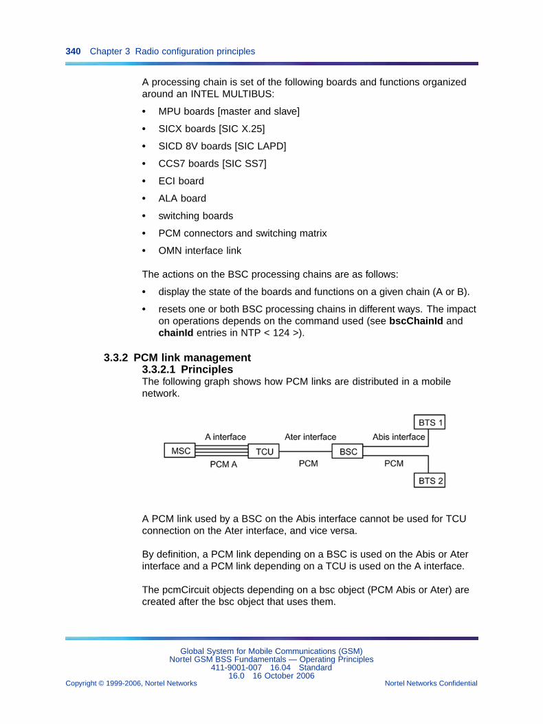
340 Chapter 3 Radio configuration principles
A processing chain is set of the following boards and functions organizedaround an INTEL MULTIBUS:
• MPU boards [master and slave]
• SICX boards [SIC X.25]
• SICD 8V boards [SIC LAPD]
• CCS7 boards [SIC SS7]
• ECI board
• ALA board
• switching boards
• PCM connectors and switching matrix
• OMN interface link
The actions on the BSC processing chains are as follows:
• display the state of the boards and functions on a given chain (A or B).
• resets one or both BSC processing chains in different ways. The impacton operations depends on the command used (see bscChainId andchainId entries in NTP < 124 >).
3.3.2 PCM link management3.3.2.1 PrinciplesThe following graph shows how PCM links are distributed in a mobilenetwork.
A PCM link used by a BSC on the Abis interface cannot be used for TCUconnection on the Ater interface, and vice versa.
By definition, a PCM link depending on a BSC is used on the Abis or Aterinterface and a PCM link depending on a TCU is used on the A interface.
The pcmCircuit objects depending on a bsc object (PCM Abis or Ater) arecreated after the bsc object that uses them.
Global System for Mobile Communications (GSM)Nortel GSM BSS Fundamentals — Operating Principles
411-9001-007 16.04 Standard16.0 16 October 2006
Copyright © 1999-2006, Nortel Networks Nortel Networks Confidential
.
3.3 Radio entity management principles 341
The pcmCircuit objects depending on a transcoder object (PCM A) arecreated after the transcoder object that uses them.
3.3.2.2 PCM link management on the Abis interface for the BSC12000HCThe bscSitePcmList attribute of a btsSiteManager object identifies theAbis interface PCM links used by the radio site (maximum of six) in the listof PCMs allotted to the BSC that controls the site.
An Abis interface PCM link is identified on BSC side by a pcmCircuitBscreference and on BTS side by a pcmCircuitBtsSiteManager reference.
The reference numbers identifying a PCM link are directly related to thenumber of the boards to which the link is physically connected on both sidesof the interface: a DDTI board in the BSC to a DTI board in the BTS.
The following rule applies:
• The reference of a PCM link connected to DDTI no.i board in the BSC12000HC is pcmCircuitBsc "2i" or "2i+1" (a DDTI board manages twoPCM links). The board numbers and positions in the BSC 12000HCequipment cabinet are cross-referenced in the BSC 12000HC ReferenceManual.
• The reference of the same PCM link connected to DTI no.j board inthe BSC in the BTS is pcmCircuitBtsSiteManager "j" (a DTI boardmanages one PCM link). The board numbers and positions in BTScabinets are cross-referenced in the BTS Reference Manuals.
3.3.2.3 PCM link management on the Abis interface for the BSC3000The bscSitePcmList attribute of a btsSiteManager object identifies theAbis interface PCM links used by the radio site in the list of PCMs allotted tothe BSC 3000 that controls the site.
An Abis interface PCM link is identified on the BSC 3000side by a pcmCircuitBsc reference and on BTS side by apcmCircuitBtsSiteManager reference.
The reference numbers identifying a PCM link are directly related to thenumber of boards that are physically connected to the interface : theLSA-RC module. There can be up to 6 LSA-RCs in a BSC 3000 and theseare identified by an id = [0...5] linked to their slot position in the cabinet.Each LSA-RC can host up to 21 E1 PCM or 28 T1 PCM links.
The following rule applies :
• The reference of a PCM link on BSC 3000 side is given by :
PCM_Number = 21 * LSA_Number + Port_Number to an E1 type BSC3000
Global System for Mobile Communications (GSM)Nortel GSM BSS Fundamentals — Operating Principles
411-9001-007 16.04 Standard16.0 16 October 2006
Copyright © 1999-2006, Nortel Networks Nortel Networks Confidential
.
342 Chapter 3 Radio configuration principles
PCM_Number = 28 * LSA_Number + Port_Number to a T1 type BSC3000
The LSA-RC module numbers and positions in BTS in the interfacenode (in BSC 3000 equipment cabinet) are referred to in NTP <126>.
• The PCM0, PCM1, PCM2 and PCM4 of LSA-RC0 (corresponding to theports 0 2 4 of port LSA-RC0) are reserved for the Ater interface butcannot be modified during the startup.
• The PCM1, PCM3 and PCM5 of LSA-RC0 (corresponding to the ports1, 3, 5 of port LSA-RC0) are reserved for the Ater interface and they canbe modified by any value of the list :
— ports [1, 2, 5 to 20] equivalents PCM1, PCM3, PCM5 to PCM20for PCM E1
— ports [1, 3, 5 to 27] equivalents PCM1, PCM3, PCM5 to PCM27for PCM T1
Thus the following rules should be considered :
• for the type of PCM E1 link :
— It is possible to use PCM6 to PCM20 on LSA-RC0, like all the othersPCM of other LSA-RC for the A or Ater link, with in more someconventions of distribution.
— To distribute PCM E1 link on different LSA-RC for a BSC 3000cabinet.
— To distribute PCM E1 link on different LSA-RC of the MSC.
• for the type of PCM T1 link :
— It is possible to use PCM3 to PCM21 on LSA-RC0, like all the othersPCM of other LSA-RC for the A or Ater link, with in more someconventions of distribution.
— To distribute PCM T1 link on different LSA-RC for a BSC 3000cabinet.
— To distribute PCM T1 link on different LSA-RC of the MSC.
Convention of classification of PCMs.
the classification of the PCM is established following rules :
• for the PCM E1 link :
— dedicated to the Ater interface, start with PCM0 and allocate thePCM numbers in ascending order.
— dedicated to interface A, start with PCM4 and allocate the PCMnumbers in descending order.
Global System for Mobile Communications (GSM)Nortel GSM BSS Fundamentals — Operating Principles
411-9001-007 16.04 Standard16.0 16 October 2006
Copyright © 1999-2006, Nortel Networks Nortel Networks Confidential
.
3.3 Radio entity management principles 343
• for the PCM T1 link :
— dedicated to the Ater interface, start with PCM0 and allocate thePCM numbers in ascending order.
— dedicated to interface A, start with PCM21 and allocate the PCMnumbers in descending order.
3.3.2.4 Radio site usable PCM time slot managementThe radioSiteMask attribute of a btsSiteManager object defines the PCMtime slots (TSs) that a radio site is allowed to use and helps manage the"drop & insert" connections on the Abis interface. According to convention,the TSs are allocated in descending numerical order. The allocation usuallybegins with bit 31 if PCM E1 links are used and bit 24 if PCM T1 links areused.
The user assigns the site scheduled time slot (attribute pcmTimeSlot-Number), that is the PCM time slot used by the site BCF OML link forinitializing all BTS communication with the BSC. Although it belongs to thesite, the scheduled time slot must be masked in the radioSiteMask to avoidbeing allocated by the BSC.
In a BTS chain, several sites share a same PCM link. Configurationrestrictions are as follows:
• Different usable time slots must be allotted to each site (separatemasks).
• All the scheduled time slots of the radio sites in the chain must bemasked in the radioSiteMask of each site.
In the case of a BTS mono PCM (star, drop & insert) or BTS single loop,if the number of defined TS for the "radio site mask" is greater than thenumber of really used TS, the remaining bits (the most significant bits) arenever used for traffic management purpose.
3.3.2.5 TEI address managementTEI address allocation In a BTS chain, the TEI addresses must beallocated in ascending order (TEI0, TEI1, TEI2, etc.), beginning with theBTS closest to the BSC.
In a BTS loop configuration, the TEI addresses must be allocated inascending order (TEI0, TEI1, TEI2, etc.), beginning with the BTS directlylinked to the BSC that uses DTI board no.0 for the Abis link input.
Relation TEI scheduled time slot When a PCM switching matrix isused between the BSC and the BTS, the relation "scheduled time slot =teiBtsSiteManager + 1" needs not be true at BSC level; otherwise, it mustbe true.
Global System for Mobile Communications (GSM)Nortel GSM BSS Fundamentals — Operating Principles
411-9001-007 16.04 Standard16.0 16 October 2006
Copyright © 1999-2006, Nortel Networks Nortel Networks Confidential
.
344 Chapter 3 Radio configuration principles
The relation remains true at BTS level in all cases.
3.3.2.6 PCM link management on the Ater and A interfacesA TCU is connected to a BSC by a PCM link identified in relation to the BSC(pcmCircuit object on Ater interface called Ater PCM).
A TCU is connected to the MSC by four PCM links identified in relation to theTCU (pcmCircuit objects on A interface called PCM A) and numbered 0 to 3.
Two TCUs cannot use the same PCM links.
For the BSC 3000 there can be several Ater links per TCU 3000 (up to 17for MIC E1 of the TCU 3000 and 21 for the MIC T1 of the TCU 3000). Thenumber of links on interface A is larger for TCU 3000 (up to 62 for the MICE1 and 82 for the MIC T1).
3.3.2.7 PCM time slot configuration on the Ater and A interfacesA 64 kbps time slot (TS) on an Ater PCM conveys four logical 16 kbps TSs.A 64 kbps time slot (TS) on a PCM A conveys one logical 64 kbps TS.
By definition, an SS7 signalling link occupies a 64 kbps TS on the Aterinterface and a 64 kbps TS on the A interface.
By definition, a terrestrial traffic circuit occupies a 16 kbps TS on the Aterinterface and a 64 kbps TS on the A interface.
For the TCU 2G Time slot mapping of the Ater PCM link assigned to aTCU on the four PCM links used by the TCU on the A interface is defined inthe transcoding unit hardware configuration data (see the transcoderMatrixentry in NTP < 124 >).
Configuration requirements are as follows:
• TS 1 on the Ater PCM is assigned to LAPD signalling between the BSCand the TCU. It has no A interface equivalent.
• The X.25 connection between the BSC and the OMC-R (OMC channel),if any, occupies TS 2 on the Ater PCM and TS 2 on PCM A no.0.
• A first-created SS7 signalling link occupies TS 3 or 2 on the Ater PCM,depending on whether the OMC channel exists, regardless of the PCMand TS allotted by users on the A interface.
• A second-created SS7 signalling link occupies TS 4 or 3 on the AterPCM, depending on whether the OMC channel exists, regardless of thePCM and TS allotted by users on the A interface.
• If PCM E1 links are used, TSs 28 to 31 on PCM A no.3 cannot be usedsince they have no Ater interface equivalent.
Global System for Mobile Communications (GSM)Nortel GSM BSS Fundamentals — Operating Principles
411-9001-007 16.04 Standard16.0 16 October 2006
Copyright © 1999-2006, Nortel Networks Nortel Networks Confidential
.
3.3 Radio entity management principles 345
• If PCM T1 links are used, TSs 21 to 24 on PCM A no.3 cannot be usedsince they have no Ater interface equivalent.
Terrestrial traffic circuit preemption conditions are as follows:
Configuration PCM A no.0 PCM Ater
OMC channel or one SS7 link TSs 1 to 4 preempted TS 2 reserved
OMC channel + one SS7 linkor two SS7 links
TSs 1 to 8 preempted TSs 2 to 3 reserved
OMC channel + two SS7 linksor three SS7 links
TSs 1 to 12preempted
TSs 2 to 4 reserved
OMC channel + three SS7links or four SS7 links
TSs 1 to 16preempted
TSs 2 to 5 reserved
Terrestrial traffic circuit preemption is effective if the SS7 signalling link(s)is(are) created and in service (signallingLink object(s) unlocked).
For the TCU 3000 Time slot mapping of the Ater PCM links is manageddynamically by the TCU 3000.
LAPD and SS7 channels are distributed in the PCM available on the Aterinterface.
3.3.2.8 PCM fault management for BTSs in Drop and InsertconfigurationIntroduction This feature (FM1189 - D&I PCM Fault Management)improves PCM fault detection on the following BTSs:
• S8000 BTS with BCF
• S8000 BTS with CBCF
• S8002 BTS with CBCF
• S2000 H/L BTS
• e-cell
It allows the BTSs in Drop and Insert configuration (from the first BTS to thelast but one) to supervise the odd PCM ports connected with a physical link,in order to detect the level 1 transmission network link failures.
Principles
• in V12.2 release, an alarm (with fault number 1067 and the cause"PCM" 6488065 on the PCM equipment) can raise only for the BTSPCM links described through the bscSitePcmList parameter (six PCMlinks at the maximum).
Global System for Mobile Communications (GSM)Nortel GSM BSS Fundamentals — Operating Principles
411-9001-007 16.04 Standard16.0 16 October 2006
Copyright © 1999-2006, Nortel Networks Nortel Networks Confidential
.
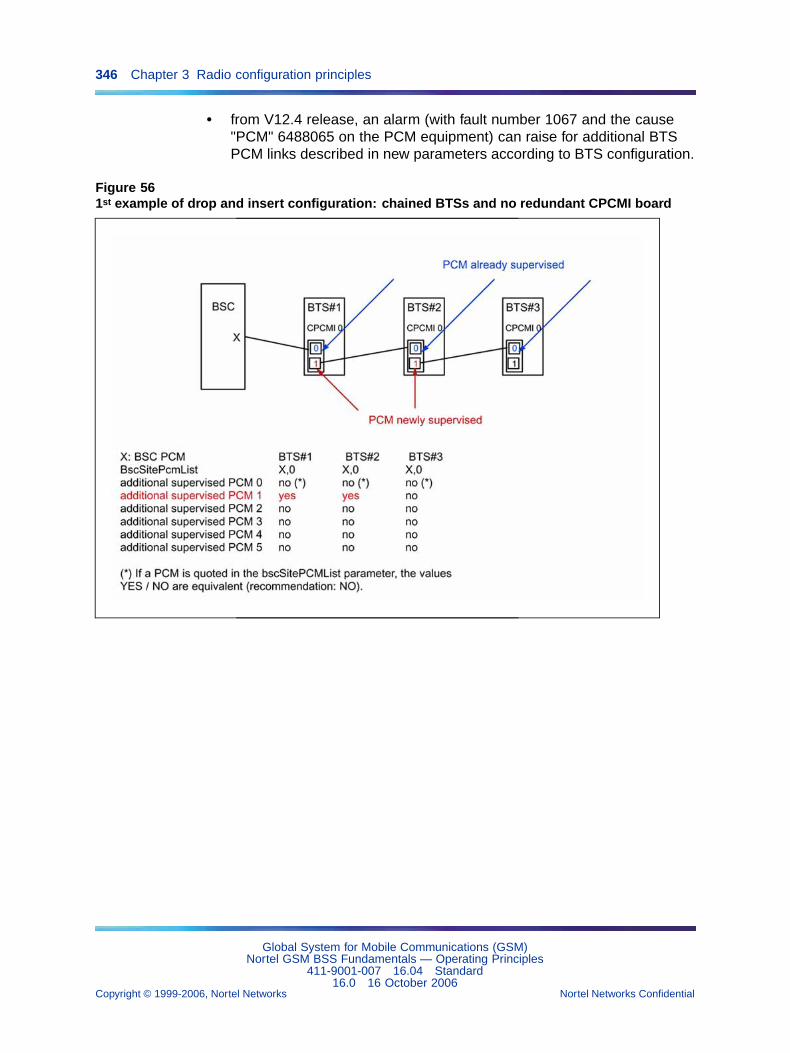
346 Chapter 3 Radio configuration principles
• from V12.4 release, an alarm (with fault number 1067 and the cause"PCM" 6488065 on the PCM equipment) can raise for additional BTSPCM links described in new parameters according to BTS configuration.
Figure 561st example of drop and insert configuration: chained BTSs and no redundant CPCMI board
Global System for Mobile Communications (GSM)Nortel GSM BSS Fundamentals — Operating Principles
411-9001-007 16.04 Standard16.0 16 October 2006
Copyright © 1999-2006, Nortel Networks Nortel Networks Confidential
.
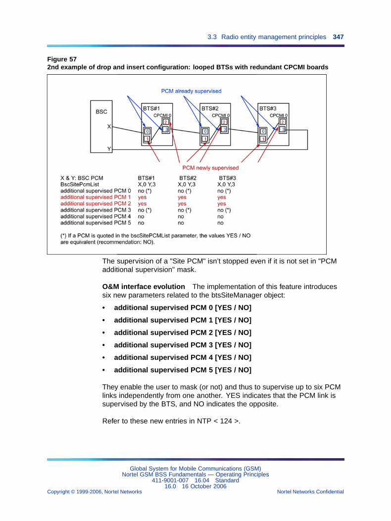
3.3 Radio entity management principles 347
Figure 572nd example of drop and insert configuration: looped BTSs with redundant CPCMI boards
The supervision of a "Site PCM" isn’t stopped even if it is not set in "PCMadditional supervision" mask.
O&M interface evolution The implementation of this feature introducessix new parameters related to the btsSiteManager object:
• additional supervised PCM 0 [YES / NO]
• additional supervised PCM 1 [YES / NO]
• additional supervised PCM 2 [YES / NO]
• additional supervised PCM 3 [YES / NO]
• additional supervised PCM 4 [YES / NO]
• additional supervised PCM 5 [YES / NO]
They enable the user to mask (or not) and thus to supervise up to six PCMlinks independently from one another. YES indicates that the PCM link issupervised by the BTS, and NO indicates the opposite.
Refer to these new entries in NTP < 124 >.
Global System for Mobile Communications (GSM)Nortel GSM BSS Fundamentals — Operating Principles
411-9001-007 16.04 Standard16.0 16 October 2006
Copyright © 1999-2006, Nortel Networks Nortel Networks Confidential
.
348 Chapter 3 Radio configuration principles
3.3.2.9 Displaying PCM information and Agprs compression rateThe "Display PCM information & Agprs compression rate" feature (26560),introduced in V15.1, collects PCM information from the OMC-R databasesand displays it in a GUI.
There are two modes of operation:
• Detailed PCM view
• Agprs resource distribution.
Detailed PCM view In this mode, you can see information about allPCM links on the Abis, Ater, and Agprs interfaces and about the objectsconnected to a given PCM link. The information is displayed in anhierarchical tree form.
Agprs resource distribution In this mode (which is also known as Agprscompression rate mode), the compression rate, the PCUSN Id, BSC Id,the number of PDTCHs per BSC, the and the number of Agprs TSs, aredisplayed. Such information can be used to make more efficient use ofPCM resources (E1/T1).
The feature is implemented as a new NRP plug-in. The operator selectsthe mode using a parameter of the NRP plug-in. The mode cannot bechanged while the NRP plug-in is running. If desired, the operator cande-activate the feature. For a description of this plug-in, refer to thedocument DS/BSS/APP/012277 (Plug-in for Display PCM Information andAgprs Compression Rate).
3.3.3 LAPD link management3.3.3.1 PrinciplesThe Link Access Protocol on D channel (LAPD) links handle signallingexchanges between the BSCs and the following entities: radio site BCFand TRX/DRX entities on the Abis interface, remote transcoders on theAter interface and packet control unit support node on the Agprs interface.Figure 58 "LAPD link management in a BSS (with BSC 12000HC)" (page352) shows how LAPD links are managed in a BSS.
The lapdLink objects are characterized by the following:
• a LAPD terminal in the BSC 12000HC (SICD 8V port number) definedby users.
• For the BSC 3000 there is no real terminal number: as for the BSC12000HC, the operator will be able to set the LAPDTerminalNumberassociated with each TEI (BTS and TRX). But now, theLAPDTerminalNumber is interpreted as the value LAPD port, and is nolonger the number of the real LAPD port of the a SICD 8V.
• a Service Access Point Identifier (SAPI) defined by users
Global System for Mobile Communications (GSM)Nortel GSM BSS Fundamentals — Operating Principles
411-9001-007 16.04 Standard16.0 16 October 2006
Copyright © 1999-2006, Nortel Networks Nortel Networks Confidential
.
3.3 Radio entity management principles 349
• an assigned interface (Abis or Ater) defined by users that tells whichtype of signalling is supported (BTS or TCU)
• a Terminal Endpoint Identifier (TEI) address allocated by the OMC-Ragent according to the TEI address allocated by users to the BCF,TRX/DRX, or TCU entity using the LAPD link
• a (pcmCircuit, timeSlotNumber) combination allocated by the OMC-Ragent that identifies the PCM TS used
In a BSS, an LAPD link is assigned to the Abis or Ater interface, never toboth. An LAPD Abis link cannot use the same:
• BSC SICD 8V port as an LAPD Ater link
• BSC 3000 TMU does not have a TMU port. There is no such limitationfor the BSC 3000. The Abis LAPD are managed by the cell group theyare related to. Ater LAPD processes are distributed independently onthe available TMUs.
Only for BSC 12000HC: LAPD concentration is always true on theAter interface. It can be true on the Abis interface, provided the BSCis consequently configured and equipped with BSCBs (BTS signallingconcentrating boards).
For the BSC 3000 there is no LAPD concentration because there is no portlimitation due to the SICD 8V card. The LAPD data is routed internallyand processed by the TMU.
At least one LAPD link must be defined for a radio site to support signallingwith its BCF.
A lapdLink object has no administrativeState of its own. Its operationalStatedepends on the administrativeState of the parent bsc object.
3.3.3.2 Main and secondary LAPDsMain LAPD The TS number carrying the main LAPD, called the RDV(Rendez-vous) TS, obeys the following BTS rule:
RDV TS number = TEI_bcf_number + 1.
The following tables indicate the link between the BTS RDV TS number(BTS matrix) and the BTS external PCM TS number.
Global System for Mobile Communications (GSM)Nortel GSM BSS Fundamentals — Operating Principles
411-9001-007 16.04 Standard16.0 16 October 2006
Copyright © 1999-2006, Nortel Networks Nortel Networks Confidential
.
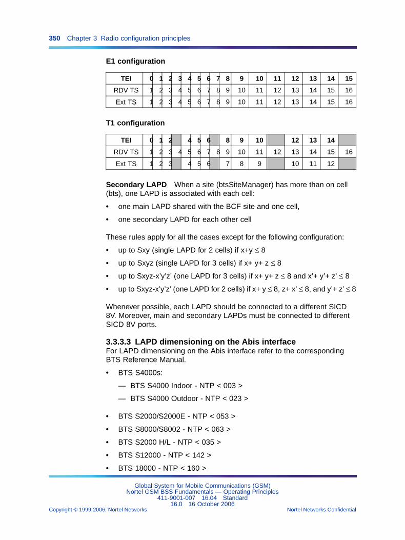
350 Chapter 3 Radio configuration principles
E1 configuration
TEI 0 1 2 3 4 5 6 7 8 9 10 11 12 13 14 15
RDV TS 1 2 3 4 5 6 7 8 9 10 11 12 13 14 15 16
Ext TS 1 2 3 4 5 6 7 8 9 10 11 12 13 14 15 16
T1 configuration
TEI 0 1 2 4 5 6 8 9 10 12 13 14
RDV TS 1 2 3 4 5 6 7 8 9 10 11 12 13 14 15 16
Ext TS 1 2 3 4 5 6 7 8 9 10 11 12
Secondary LAPD When a site (btsSiteManager) has more than on cell(bts), one LAPD is associated with each cell:
• one main LAPD shared with the BCF site and one cell,
• one secondary LAPD for each other cell
These rules apply for all the cases except for the following configuration:
• up to Sxy (single LAPD for 2 cells) if x+y ≤ 8
• up to Sxyz (single LAPD for 3 cells) if x+ y+ z ≤ 8
• up to Sxyz-x’y’z’ (one LAPD for 3 cells) if x+ y+ z ≤ 8 and x’+ y’+ z’ ≤ 8
• up to Sxyz-x’y’z’ (one LAPD for 2 cells) if x+ y ≤ 8, z+ x’ ≤ 8, and y’+ z’ ≤ 8
Whenever possible, each LAPD should be connected to a different SICD8V. Moreover, main and secondary LAPDs must be connected to differentSICD 8V ports.
3.3.3.3 LAPD dimensioning on the Abis interfaceFor LAPD dimensioning on the Abis interface refer to the correspondingBTS Reference Manual.
• BTS S4000s:
— BTS S4000 Indoor - NTP < 003 >
— BTS S4000 Outdoor - NTP < 023 >
• BTS S2000/S2000E - NTP < 053 >
• BTS S8000/S8002 - NTP < 063 >
• BTS S2000 H/L - NTP < 035 >
• BTS S12000 - NTP < 142 >
• BTS 18000 - NTP < 160 >
Global System for Mobile Communications (GSM)Nortel GSM BSS Fundamentals — Operating Principles
411-9001-007 16.04 Standard16.0 16 October 2006
Copyright © 1999-2006, Nortel Networks Nortel Networks Confidential
.
3.3 Radio entity management principles 351
Starting with the V14 release, considering the actual proportion of AMRmobiles in the network, the classical dimensioning of one LAPD for 8 TRXscan be sufficient.
3.3.3.4 LAPD channel management on the Abis interfaceA radio site uses one LAPD link with OML sapi for operations andmaintenance.
A TRX/DRX uses two LAPD links, one with OML sapi for operations andmaintenance, the other with RSL sapi for carrying data.
The LAPD channel TEI addresses on the Abis interface are allocated byusers when the btsSiteManager or transceiverEquipment objects that usethem are created.
If several radio site LAPD channels use the same BSC SICD 8V port orTMU port, they also use the same PCM time slot. The following apply:
• If one of the channels supports the radio site BCF link, the TS equalsthe radio site scheduled time slot (pcmTimeSlotNumber attribute of theconcerned btsSiteManager object). The OMC-R agent supplies theBSC with the information.
• If all the channels are allocated to the radio site TRX/DRXs, the BSCselects the TS from the usable radio site time slots (radioSiteMaskattribute).
The same LAPD channel can be allocated on the Abis interface to supportthe links with a radio site BCF and eight TRX/DRXs. This corresponds tonine lapdLink object instances with OML sapi and eight lapdLink objectinstances with RSL sapi.
3.3.3.5 Effect of satellite links on Abis interfaceThe Satellite link on BSS Abis (E1) feature (26834), introduced in V15.1,allows the implementation of satellite links instead of terrestrial links onthe Abis interface.
In some network areas, there is no terrestrial transmission infrastructurebetween the BSC and the BTS. The 26834 feature solves this problem byenabling a satellite link to be used instead. However, because of the extratime taken to go to/from the satellite, the propagation delay between BSC toBTS increases from a few milliseconds to more than 200 milliseconds. AllAbis OAM procedures take longer. LAPD capacity is reduced (and LAPDparameters have to be tuned).
Feature 26834 is an optional feature.
Global System for Mobile Communications (GSM)Nortel GSM BSS Fundamentals — Operating Principles
411-9001-007 16.04 Standard16.0 16 October 2006
Copyright © 1999-2006, Nortel Networks Nortel Networks Confidential
.
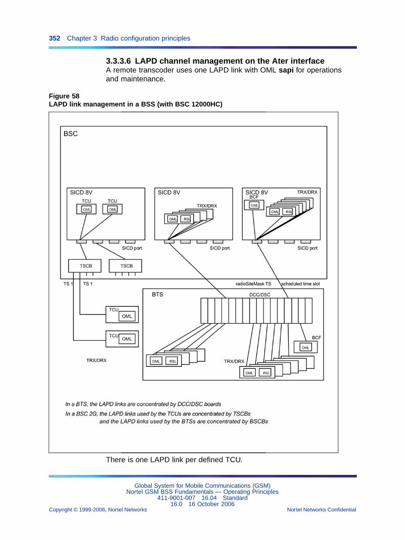
352 Chapter 3 Radio configuration principles
3.3.3.6 LAPD channel management on the Ater interfaceA remote transcoder uses one LAPD link with OML sapi for operationsand maintenance.
Figure 58LAPD link management in a BSS (with BSC 12000HC)
There is one LAPD link per defined TCU.
Global System for Mobile Communications (GSM)Nortel GSM BSS Fundamentals — Operating Principles
411-9001-007 16.04 Standard16.0 16 October 2006
Copyright © 1999-2006, Nortel Networks Nortel Networks Confidential
.
3.3 Radio entity management principles 353
3.3.4 Concentric cells3.3.4.1 PrinciplesA cell is defined as concentric if two pools of resources (TDMAs) are definedusing RxLev and optionally Timing Advance as allocation criteria. One ortwo types of TRXs/DRXs can be used.
Thus a concentric cell describes a combination of two transmission zones,the outer (large) zone and the inner (small) zone.
The different types of concentric cells are the following:
• dualzone
The two pools of TRXs/DRXs are configured to transmit at differentpowers. Thus transmission powers being different result in two differentcoverage areas.
The concentric cell bts object attribute is set to "concentric". Refer tothis entry in NTP < 124 >.
• dualcoupling
The two pools of TRXs/DRXs are not combined with the same types ofcombiners. Thus coupling losses being different results in two differentcoverage areas.
The concentric cell bts object attribute is set to "dualcoupling". Refer tothis entry in NTP < 124 >.
Only S8000 DRXs cells can be "dualcoupling".
• dualband
One pool of GSM 900 TRXs/DRXs and one pool of GSM 1800TRXs/DRXs are defined and share the same BCCH in the GSM 900 orGSM 1800 frequency band. Thus propagation losses being differentresults in two different coverage areas.
The concentric cell bts object attribute is set to "dualband". Refer tothis entry in NTP < 124 >.
Only cells whose transceiver architecture is non mixed DCU4 or DRXcan be "dualband".
3.3.4.2 Customer benefitsThe customer benefits of the use of concentric cells are the following:
• dualzone
For an equivalent coverage in terms of geographic area and numberof used TDMA frames, it allows to minimize the number of usefulfrequencies.
For the same band of useful frequencies it allows to increase the numberof used TDMA frames, and therefore the number of network users.
Global System for Mobile Communications (GSM)Nortel GSM BSS Fundamentals — Operating Principles
411-9001-007 16.04 Standard16.0 16 October 2006
Copyright © 1999-2006, Nortel Networks Nortel Networks Confidential
.
354 Chapter 3 Radio configuration principles
• dualcoupling
This configuration allows capacity increase (number of DRXs) whilemaintaining superior coverage without reducing cell coverage i.e. sameEIRP (Equivalent Isotropic Radiated Power) for the BCCH frequencytransmission.
• dualband
Having GSM 900 and GSM 1800 TRXs/DRXs in the same cell providesa strong capacity. This capacity enhancement is efficient in terms oftransmission costs and traffic management thanks to band prioritizationmechanisms.
3.3.4.3 Radio resource configurationThe TDMA frames used by concentric cells are shared between the outerzone and the inner zone. The difference between the partnered TRX/DRXsin each zone is based on the maximum allowed transmission power
The hardware specifications of the TDMA frames may differ from one zoneto another, but, in that case, the frames that belong to one zone cannot bereconfigured to be used in the other zone.
All common channels, such as the cell BCCH, are carried on TDMA framesthat belong to the outer zone.
3.3.4.4 Radio resource managementIn all the cases the BCCH frequency is carried on a TDMA frame thatbelongs to the outer zone.
From V12, the Direct TCH allocation in the small zone feature (TF889)enhances handover mechanisms. This enables to avoid a subsequent intracell (from large to small zone) handover whilst allocating a TCH (call set up)or handing over directly into the inner zone of a concentric cell.
The direct handover towards the inner zone of a concentric cell is onlyallowed for intra-BSS handovers.
An intra-zone handover in a concentric cell is managed in the same wayas an intra-bts handover in a non-concentric cell. It only calls on the radioresources in one zone, which means that the newly assigned radio resourcealways belongs to the same zone as the radio resource that is released.
3.3.4.5 Frequency managementThe Frequency reuse in both zones feature (CM888) allows fractional reusetechniques which enable to define one set of frequencies (except the BCCHfrequency) usable by all the DRXs in both zones of a concentric cell.
Global System for Mobile Communications (GSM)Nortel GSM BSS Fundamentals — Operating Principles
411-9001-007 16.04 Standard16.0 16 October 2006
Copyright © 1999-2006, Nortel Networks Nortel Networks Confidential
.
3.4 Radio measurement processing 355
3.3.5 Software management3.3.5.1 The software objectThe software objects are associated with bsc, btsSiteManager,transceiverEquipment, and transcoderBoard objects.
Software object attributes are updated by download and change versionactions. They identify the BSS entity software versions loaded on the BSCdisk involved as follows:
• The sWVersionBackUp attribute identifies the backup software version.It is identical to sWVersionRunning.
• The sWVersionFallback attribute identifies the software versionthat was operational before the current version was activated andis reinstalled in response to a Return to previous versioncommand
• The sWVersionNew attribute identifies the last software versiondownloaded to the BSC disk with a Download command or softwareversion that was running but is no longer running after a Return toprevious version command
• The sWVersionRunning attribute identifies the software versioncurrently running in the BSS entity. This attribute is updated wheneverthe version is changed.
If one of these attributes is not defined (NULL value), it means thatno software version is referenced by the attribute. If, for example, thesWVersionNew attribute value is "NULL", either no new version hasbeen downloaded since the BSS entity was enabled or no fallback onthe preceding version has been performed since the current version wasactivated.
The sWVersionRunning attribute of a software object is always defined.
3.3.5.2 BCF configuration file managementThe configRef attribute of a btsSiteManager object identifies the DLU (DataLoad Unit) variable configuration file which allows to configure the radio siteBCF software with parameters such as coupling mode used, number of TXtransmitters. This file is downloaded in the radio site BCF together withthe software version.
3.4 Radio measurement processingThis paragraph describes processing of radio measurements performedby mobile stations or the BTS to manage handover requests, controltransmission power, and monitor calls.
Global System for Mobile Communications (GSM)Nortel GSM BSS Fundamentals — Operating Principles
411-9001-007 16.04 Standard16.0 16 October 2006
Copyright © 1999-2006, Nortel Networks Nortel Networks Confidential
.
356 Chapter 3 Radio configuration principles
3.4.1 PrinciplesCalculations involve the measurements returned by mobile stations on thedownlink and the BTS on the uplink.
The BTS processes the radio measurements and sends the results to theBSC.
The BTS draws up a list of eligible serving cells that qualify to handle thehandover requests and sends the list to the BSC.
3.4.2 Configuration parameters
• averagingPeriod (handOverControl object)
• bsTxPowerMax (powerControl object)
• cellDeletionCount (bts object)
• distHreqt (handOverControl object)
• distWtsList (handOverControl object)
• missDistWt (handOverControl object)
• missRxLevWt (handOverControl object)
• missRxQualWt (handOverControl object)
• msTxPwrMax (bts object)
• msTxPwrMax2ndBand (bts object)
• msTxPowerMaxCell (adjacentCellHandOver object)
• new power control algorithm (bts object)
• powerBudgetInterCell (handOverControl object)
• powerControlIndicator (bts object)
• radChanSelIntThreshold (handOverControl object)
• runCallClear (bts object)
• runHandOver (bts object)
• runPwrControl (bts object)
• rxLevAccessMin (bts object)
• rxLevHreqave (handOverControl object)
• rxLevHreqaveBeg (handOverControl object)
• rxLevHreqt (handOverControl object)
• rxLevWtsList (handOverControl object)
• rxNCellHreqave (handOverControl object)
Global System for Mobile Communications (GSM)Nortel GSM BSS Fundamentals — Operating Principles
411-9001-007 16.04 Standard16.0 16 October 2006
Copyright © 1999-2006, Nortel Networks Nortel Networks Confidential
.
3.4 Radio measurement processing 357
• rxLevNCellHreqaveBeg (handOverControl object)
• rxQualHreqave (handOverControl object)
• rxQualHreqt (handOverControl object)
• rxQualWtsList (handOverControl object)
• thresholdInterference (handOverControl object)
Radio measurement control and management parameters are defined atcell level. The decisions related to power control and handover requestsmay, therefore, vary from one BSS cell to another.
3.4.2.1 Control parametersThe runXxx parameters define the time between computing and decisionmaking algorithm runs as a number of received "Measurement results"messages for each type of processing: handover (runHandOver), powercontrol (runPwrControl), and call clearing (runCallClear).
The cellDeletionCount parameter defines the number of consecutive,missing neighbor cell measurements after which the neighbor cell is ignoredand the previously stored measurements for that cell are deleted.
The measurements returned by mobile stations on the BCCH may, or maynot, be counted in calculations (powerControlIndicator).
The new power control algorithm parameter specifies which power controlalgorithm is used by the BTS to control power in a given cell: step by step(standard algorithm) or one shot (advanced algorithm).
3.4.2.2 Management parametersThe xxxHreqave / xxxHreqaveBeg parameters define the number of rawmeasurements used to calculate mean values.
The xxxHreqt parameters define the number of mean values (orraw distance measurements) weighed by xxxWtsList factors used tocalculate super-averages. The number of weights in each list equals thecorresponding xxxHreqt parameter value and the sum of the weightsequals 100.
The missXxxWt parameters define the weighting factors used to calculatethe super-averages when measurements are missing.
The averagingPeriod parameter defines the number of samplesused to calculate mean interference levels on idle channels. ThethresholdInterference parameter is used to classify idle channelsaccording to four interference levels.
Global System for Mobile Communications (GSM)Nortel GSM BSS Fundamentals — Operating Principles
411-9001-007 16.04 Standard16.0 16 October 2006
Copyright © 1999-2006, Nortel Networks Nortel Networks Confidential
.
358 Chapter 3 Radio configuration principles
3.4.3 DefinitionsParameters resulting from radio measurement processing that are usedin the various processing algorithms detailed in the following paragraphsare listed below.
• MS_BS_DIST is the arithmetic mean MS-BTS distance calculated bythe BTS which sets the timing advance used by the mobile station:
— A distance below 35 km (normal mode) corresponds to a timingadvance smaller than 63.
— A distance over 35 km (extended mode) corresponds to a timingadvance greater than 63.
• RXLEV_DL is the weighed mean signal strength level on the downlink fora serving cell, calculated by the BTS from mobile station measurements.
• RXLEV_UL is the weighed mean signal strength level on the uplink for aserving cell, calculated from the BTS self-measurements.
• RXLEV_NCELL(n) is the arithmetic mean signal strength level on thedownlink for a neighbor cell n, calculated by the BTS from informationcollected by the mobile station.
• RXQUAL_DL is the weighed mean signal quality level on the downlink fora serving cell, calculated by the BTS from mobile station measurements.
• RXQUAL_UL is the weighed mean signal quality level on the uplink for aserving cell, calculated from the BTS self-measurements.
• PBGT(n) is the power budget criterion for a neighbor cell n whenhandovers with cause "power budget" are authorized in the associatedserving cell.
• BSTxNewPower is the new BTS transmission power level in a cell,calculated by the BTS when the advanced power control algorithm isused.
• MSNewPower is the new transmission power level of a mobile stationin a cell, calculated by the BTS when the advanced power controlalgorithm is used.
• MSPowerMax is a mobile station RFPC power that depends on its class.
3.4.4 Measurement processingThe decision making algorithm is described in Section 3.6 "Handovermanagement" (page 372) to Section 3.8 "Call monitoring" (page 415).
Global System for Mobile Communications (GSM)Nortel GSM BSS Fundamentals — Operating Principles
411-9001-007 16.04 Standard16.0 16 October 2006
Copyright © 1999-2006, Nortel Networks Nortel Networks Confidential
.
3.4 Radio measurement processing 359
3.4.4.1 Mean distance calculationsWhen runCallClearing or runHandOver "Measurement results" messageshave been received, the L1M function in the BTS weighs distHreqt rawdistance measurements with the weights defined in distWtsList andcalculates distance super-averages as follows:
MS_BS_DIST = [∑ (measurementj × weightj)] / 100, j = 1 to distHreqt
Each measurement is associated with one, and only one weight. Theassociations are established in sequence, in the order which the weightsare listed. The last received measurement is always associated with thefirst weight in the list.
Any missing measurement is replaced by the last received raw measurementweighed by the missDistWt factor.
The BTS does not calculate mean distances. The raw measurements areused in the super-average calculation.
3.4.4.2 Mean signal strength calculationsServing cells When rxLevHreqave / rxLevHreqaveBeg measurementshave been received, the L1M function in the BTS calculates the meansignal strength level on the downlink and uplink from raw measurements, asfollows:
downlink Mean = ∑ (downlink measurementi) / rxLevHreqave(rxLevHreqaveBeg), i = 1 to rxLevHreqave (rxLevHreqaveBeg)uplink Mean = ∑ (uplink measurement i) / rxLevHreqave(rxLevHreqaveBeg), i = 1 to rxLevHreqave (rxLevHreqaveBeg)
When runCallClearing, runHandOver, or runPwrControl "Measurementresults" messages have been received, the L1M function in the BTSweighs the calculated rxLevHreqt mean values with the weights defined inrxLevWtsList and calculates the signal strength super-averages as follows:
RXLEV_DL = [∑ (downlink Meanj × weightj)] / 100, j = 1 to rxLevHreqtRXLEV_UL = [∑ (uplink Meanj × weightj)] / 100, j = 1 to rxLevHreqt
Each measurement is associated with one, and only one weight. Theassociations are established in sequence, in the order which the weightsare listed. The last received measurement is always associated with thefirst weight in the list.
Any missing measurement is replaced by the last calculated mean value,or by the last received raw measurement if no mean value is available,weighed by the missRxLevWt factor.
Global System for Mobile Communications (GSM)Nortel GSM BSS Fundamentals — Operating Principles
411-9001-007 16.04 Standard16.0 16 October 2006
Copyright © 1999-2006, Nortel Networks Nortel Networks Confidential
.
360 Chapter 3 Radio configuration principles
Super-averaging is optimal when the time between two algorithm runs is amultiple of rxLevHreqave / rxLevHreqaveBeg
Serving microcells When rxLevHreqave / rxLevHreqaveBegmeasurements have been received, the L1M function in the BTS alsoevaluates the difference between the last two calculated mean signalstrength values on the downlink as follows:
E = downlink Meanj - downlink Meanj-1
Neighbor cells When rxNCellHreqave / rxLevNCellHreqaveBegmeasurements have been received, the L1M function in the BTS calculatesthe mean signal strength levels in neighbor cells on the downlink from rawmeasurements, as follows:
Mean(n) = ∑ (measurementi(n)) / rxNCellHreqave (rxLevNCellHre-qaveBeg), i = 1 to rxNCellHreqave (rxLevNCellHreqaveBeg)
When runHandOver "Measurement results" messages have been received,the L1M function in the BTS calculates the neighbor cell signal strengthsuper-averages, as follows:
RXLEV_NCELL(n) = ∑ (Meanj(n)) / number of calculated mean(n)
The BTS does not calculate weighed super-average in neighbor cells.
When runHandOver "Measurement results" messages have been received,the L1M function in the BTS also evaluates the PBGT(n) parameters usingthe following formulas:
Classical case (monoband neighbor cell in the same band as theserving cell)
PBGT(n) = min(msTxPwrMax, MSPowerMax) - RXLEV_DL -(bsTxPwrMax - BSTxCurrentPower) -(min(msTxPwrMaxCell(n), MSPowerMax) - RXLEV_NCELL(n))
where:
• RXLEV_DL is the current, mean downlink signal strength level for theserving cell.
• RXLEV_NCELL(n) is the current, mean signal strength level in theneighbor cell.
• MSPowerMax is the mobile station RFPC power that depends on itsclass.
Global System for Mobile Communications (GSM)Nortel GSM BSS Fundamentals — Operating Principles
411-9001-007 16.04 Standard16.0 16 October 2006
Copyright © 1999-2006, Nortel Networks Nortel Networks Confidential
.
3.4 Radio measurement processing 361
• BSTxCurrentPower is the current BTS transmission power in theneighbor cell, updated by the power control algorithm.
Handover towards band 1 of the selected neighbor dualband cell Ifthe serving cell TDMA band is in band0
PBGT(n) = min(msTxPwrMax, MSPowerMax) - RXLEV_DL -(bsTxPwrMax - BSTxCurrentPower) -(min(msTxPwrMaxCell(n), MSPowerMax) - RXLEV_NCELL(n))
where:
• RXLEV_DL is the current, mean downlink signal strength level for theserving cell in band0.
• RXLEV_NCELL(n) is the current, mean signal strength level in theneighbor cell.
• MSPowerMax is the mobile station RFPC power that depends on itsclass.
• BSTxCurrentPower is the current BTS transmission power in theneighbor cell, updated by the power control algorithm.
If the serving cell TDMA band is in band1
PBGT(n) = min(msTxPwrMax, MSPowerMax) -(RXLEV_DL(band1) + biZonePower Offset) -(bsTxPwrMax - BSTxCurrentPower) -(min(msTxPwrMaxCell(n), MSPowerMax) - RXLEV_NCELL(n))
where:
• RXLEV_DL(band1) is the current, mean downlink signal strength levelfor the serving cell in band1.
• RXLEV_NCELL(n) is the current, mean signal strength level in theneighbor cell.
• MSPowerMax is the mobile station RFPC power that depends on itsclass.
• BSTxCurrentPower is the current BTS transmission power in theneighbor cell, updated by the power control algorithm.
• biZonePowerOffset is a corrective factor that applies to the dualbandneighbor cell cases. It enables to take into account the difference of thepropagation model between the two frequency bands of the network.
Global System for Mobile Communications (GSM)Nortel GSM BSS Fundamentals — Operating Principles
411-9001-007 16.04 Standard16.0 16 October 2006
Copyright © 1999-2006, Nortel Networks Nortel Networks Confidential
.
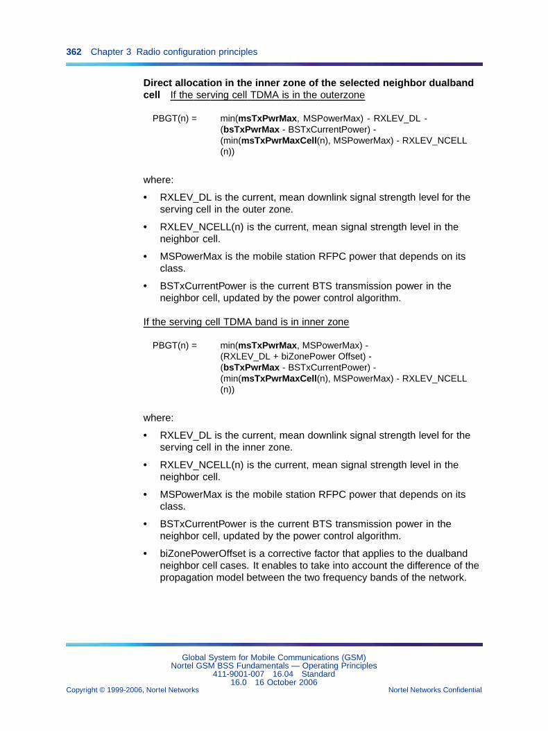
362 Chapter 3 Radio configuration principles
Direct allocation in the inner zone of the selected neighbor dualbandcell If the serving cell TDMA is in the outerzone
PBGT(n) = min(msTxPwrMax, MSPowerMax) - RXLEV_DL -(bsTxPwrMax - BSTxCurrentPower) -(min(msTxPwrMaxCell(n), MSPowerMax) - RXLEV_NCELL(n))
where:
• RXLEV_DL is the current, mean downlink signal strength level for theserving cell in the outer zone.
• RXLEV_NCELL(n) is the current, mean signal strength level in theneighbor cell.
• MSPowerMax is the mobile station RFPC power that depends on itsclass.
• BSTxCurrentPower is the current BTS transmission power in theneighbor cell, updated by the power control algorithm.
If the serving cell TDMA band is in inner zone
PBGT(n) = min(msTxPwrMax, MSPowerMax) -(RXLEV_DL + biZonePower Offset) -(bsTxPwrMax - BSTxCurrentPower) -(min(msTxPwrMaxCell(n), MSPowerMax) - RXLEV_NCELL(n))
where:
• RXLEV_DL is the current, mean downlink signal strength level for theserving cell in the inner zone.
• RXLEV_NCELL(n) is the current, mean signal strength level in theneighbor cell.
• MSPowerMax is the mobile station RFPC power that depends on itsclass.
• BSTxCurrentPower is the current BTS transmission power in theneighbor cell, updated by the power control algorithm.
• biZonePowerOffset is a corrective factor that applies to the dualbandneighbor cell cases. It enables to take into account the difference of thepropagation model between the two frequency bands of the network.
Global System for Mobile Communications (GSM)Nortel GSM BSS Fundamentals — Operating Principles
411-9001-007 16.04 Standard16.0 16 October 2006
Copyright © 1999-2006, Nortel Networks Nortel Networks Confidential
.
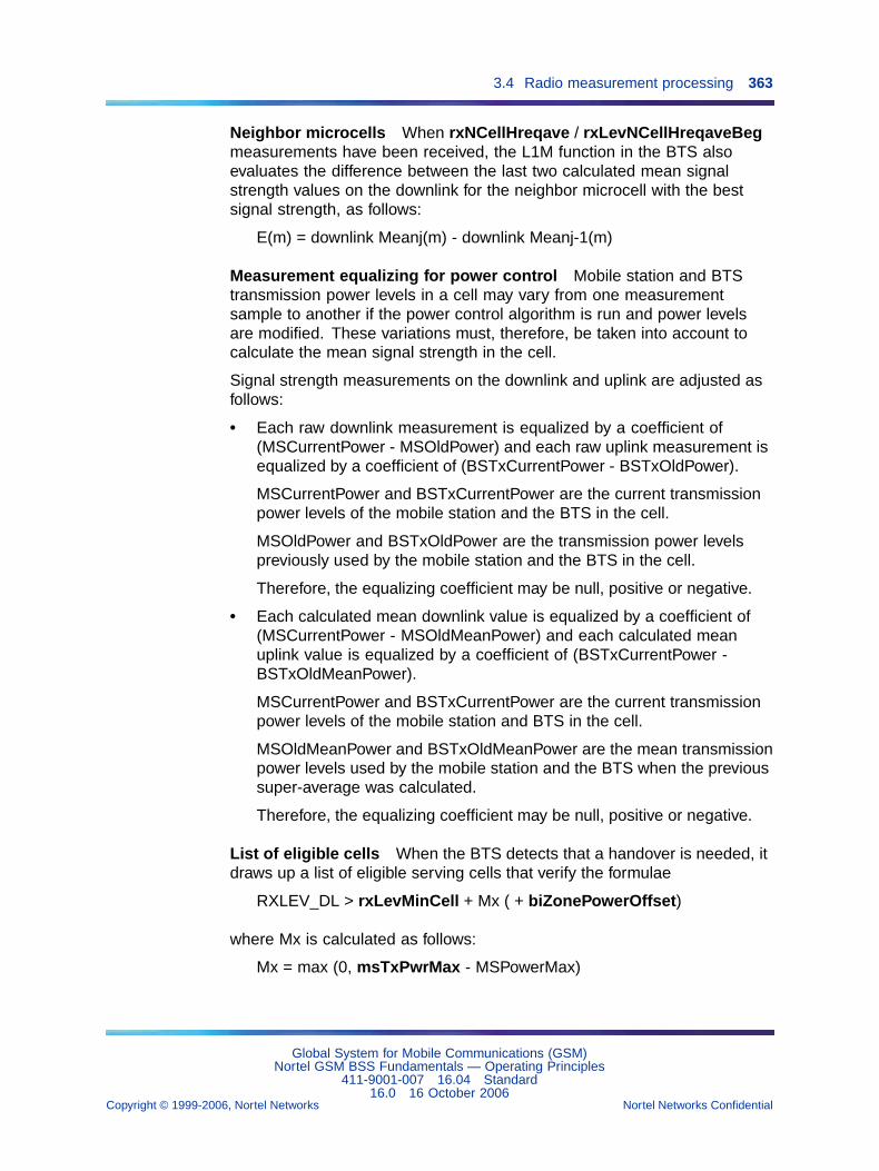
3.4 Radio measurement processing 363
Neighbor microcells When rxNCellHreqave / rxLevNCellHreqaveBegmeasurements have been received, the L1M function in the BTS alsoevaluates the difference between the last two calculated mean signalstrength values on the downlink for the neighbor microcell with the bestsignal strength, as follows:
E(m) = downlink Meanj(m) - downlink Meanj-1(m)
Measurement equalizing for power control Mobile station and BTStransmission power levels in a cell may vary from one measurementsample to another if the power control algorithm is run and power levelsare modified. These variations must, therefore, be taken into account tocalculate the mean signal strength in the cell.
Signal strength measurements on the downlink and uplink are adjusted asfollows:
• Each raw downlink measurement is equalized by a coefficient of(MSCurrentPower - MSOldPower) and each raw uplink measurement isequalized by a coefficient of (BSTxCurrentPower - BSTxOldPower).
MSCurrentPower and BSTxCurrentPower are the current transmissionpower levels of the mobile station and the BTS in the cell.
MSOldPower and BSTxOldPower are the transmission power levelspreviously used by the mobile station and the BTS in the cell.
Therefore, the equalizing coefficient may be null, positive or negative.
• Each calculated mean downlink value is equalized by a coefficient of(MSCurrentPower - MSOldMeanPower) and each calculated meanuplink value is equalized by a coefficient of (BSTxCurrentPower -BSTxOldMeanPower).
MSCurrentPower and BSTxCurrentPower are the current transmissionpower levels of the mobile station and BTS in the cell.
MSOldMeanPower and BSTxOldMeanPower are the mean transmissionpower levels used by the mobile station and the BTS when the previoussuper-average was calculated.
Therefore, the equalizing coefficient may be null, positive or negative.
List of eligible cells When the BTS detects that a handover is needed, itdraws up a list of eligible serving cells that verify the formulae
RXLEV_DL > rxLevMinCell + Mx ( + biZonePowerOffset)
where Mx is calculated as follows:
Mx = max (0, msTxPwrMax - MSPowerMax)
Global System for Mobile Communications (GSM)Nortel GSM BSS Fundamentals — Operating Principles
411-9001-007 16.04 Standard16.0 16 October 2006
Copyright © 1999-2006, Nortel Networks Nortel Networks Confidential
.
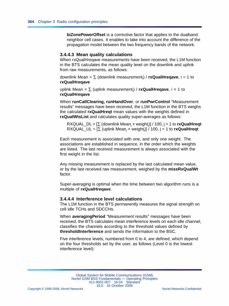
364 Chapter 3 Radio configuration principles
biZonePowerOffset is a corrective factor that applies to the dualbandneighbor cell cases. It enables to take into account the difference of thepropagation model between the two frequency bands of the network.
3.4.4.3 Mean quality calculationsWhen rxQualHreqave measurements have been received, the L1M functionin the BTS calculates the mean quality level on the downlink and uplinkfrom raw measurements, as follows:
downlink Mean = ∑ (downlink measurementi) / rxQualHreqave, i = 1 torxQualHreqave
uplink Mean = ∑ (uplink measurementi) / rxQualHreqave, i = 1 torxQualHreqave
When runCallClearing, runHandOver, or runPwrControl "Measurementresults" messages have been received, the L1M function in the BTS weighsthe calculated rxQualHreqt mean values with the weights defined inrxQualWtsList and calculates quality super-averages as follows:
RXQUAL_DL = [∑ (downlink Meanj × weightj)] / 100, j = 1 to rxQualHreqtRXQUAL_UL = [∑ (uplink Meanj × weightj)] / 100, j = 1 to rxQualHreqt
Each measurement is associated with one, and only one weight. Theassociations are established in sequence, in the order which the weightsare listed. The last received measurement is always associated with thefirst weight in the list.
Any missing measurement is replaced by the last calculated mean value,or by the last received raw measurement, weighed by the missRxQualWtfactor.
Super-averaging is optimal when the time between two algorithm runs is amultiple of rxQualHreqave.
3.4.4.4 Interference level calculationsThe L1M function in the BTS permanently measures the signal strength oncell idle TCHs and SDCCHs.
When averagingPeriod "Measurement results" messages have beenreceived, the BTS calculates mean interference levels on each idle channel,classifies the channels according to the threshold values defined bythresholdInterference and sends the information to the BSC.
Five interference levels, numbered from 0 to 4, are defined, which dependon the four thresholds set by the user, as follows (Level 0 is the lowestinterference level):
Global System for Mobile Communications (GSM)Nortel GSM BSS Fundamentals — Operating Principles
411-9001-007 16.04 Standard16.0 16 October 2006
Copyright © 1999-2006, Nortel Networks Nortel Networks Confidential
.
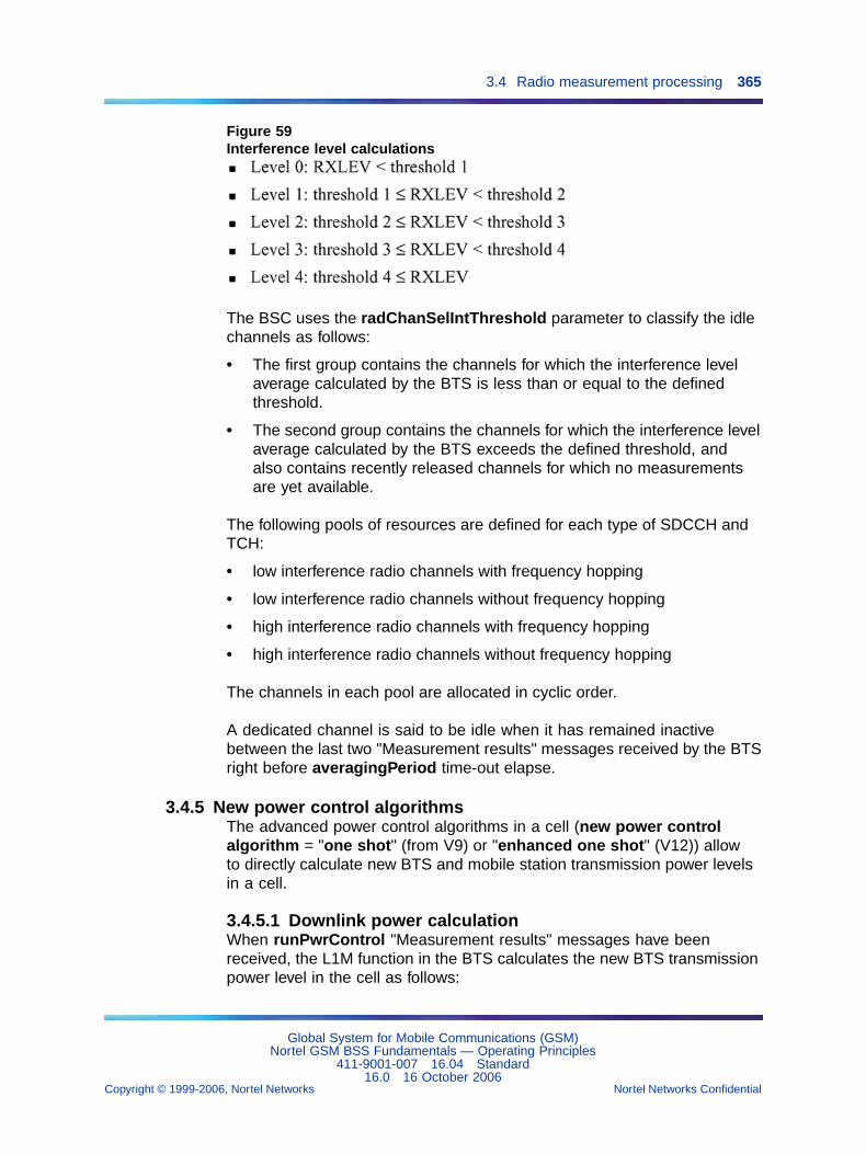
3.4 Radio measurement processing 365
Figure 59Interference level calculations
The BSC uses the radChanSelIntThreshold parameter to classify the idlechannels as follows:
• The first group contains the channels for which the interference levelaverage calculated by the BTS is less than or equal to the definedthreshold.
• The second group contains the channels for which the interference levelaverage calculated by the BTS exceeds the defined threshold, andalso contains recently released channels for which no measurementsare yet available.
The following pools of resources are defined for each type of SDCCH andTCH:
• low interference radio channels with frequency hopping
• low interference radio channels without frequency hopping
• high interference radio channels with frequency hopping
• high interference radio channels without frequency hopping
The channels in each pool are allocated in cyclic order.
A dedicated channel is said to be idle when it has remained inactivebetween the last two "Measurement results" messages received by the BTSright before averagingPeriod time-out elapse.
3.4.5 New power control algorithmsThe advanced power control algorithms in a cell (new power controlalgorithm = "one shot" (from V9) or "enhanced one shot" (V12)) allowto directly calculate new BTS and mobile station transmission power levelsin a cell.
3.4.5.1 Downlink power calculationWhen runPwrControl "Measurement results" messages have beenreceived, the L1M function in the BTS calculates the new BTS transmissionpower level in the cell as follows:
Global System for Mobile Communications (GSM)Nortel GSM BSS Fundamentals — Operating Principles
411-9001-007 16.04 Standard16.0 16 October 2006
Copyright © 1999-2006, Nortel Networks Nortel Networks Confidential
.
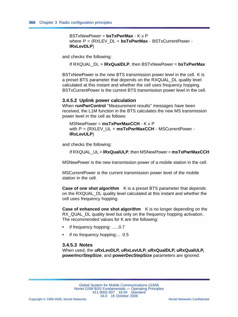
366 Chapter 3 Radio configuration principles
BSTxNewPower = bsTxPwrMax - K x Pwhere P = (RXLEV_DL + bsTxPwrMax - BSTxCurrentPower -lRxLevDLP)
and checks the following:
If RXQUAL_DL > lRxQualDLP, then BSTxNewPower = bsTxPwrMax
BSTxNewPower is the new BTS transmission power level in the cell. K isa preset BTS parameter that depends on the RXQUAL_DL quality levelcalculated at this instant and whether the cell uses frequency hopping.BSTxCurrentPower is the current BTS transmission power level in the cell.
3.4.5.2 Uplink power calculationWhen runPwrControl "Measurement results" messages have beenreceived, the L1M function in the BTS calculates the new MS transmissionpower level in the cell as follows:
MSNewPower = msTxPwrMaxCCH - K x Pwith P = (RXLEV_UL + msTxPwrMaxCCH - MSCurrentPower -lRxLevULP)
and checks the following:
If RXQUAL_UL > lRxQualULP, then MSNewPower = msTxPwrMaxCCH
MSNewPower is the new transmission power of a mobile station in the cell.
MSCurrentPower is the current transmission power level of the mobilestation in the cell.
Case of one shot algorithm K is a preset BTS parameter that dependson the RXQUAL_DL quality level calculated at this instant and whether thecell uses frequency hopping.
Case of enhanced one shot algorithm K is no longer depending on theRX_QUAL_DL quality level but only on the frequency hopping activation.The recommended values for K are the following:
• if frequency hopping: .....0.7
• if no frequency hopping:... 0.5
3.4.5.3 NotesWhen used, the uRxLevDLP, uRxLevULP, uRxQualDLP, uRxQualULP,powerIncrStepSize, and powerDecStepSize parameters are ignored.
Global System for Mobile Communications (GSM)Nortel GSM BSS Fundamentals — Operating Principles
411-9001-007 16.04 Standard16.0 16 October 2006
Copyright © 1999-2006, Nortel Networks Nortel Networks Confidential
.
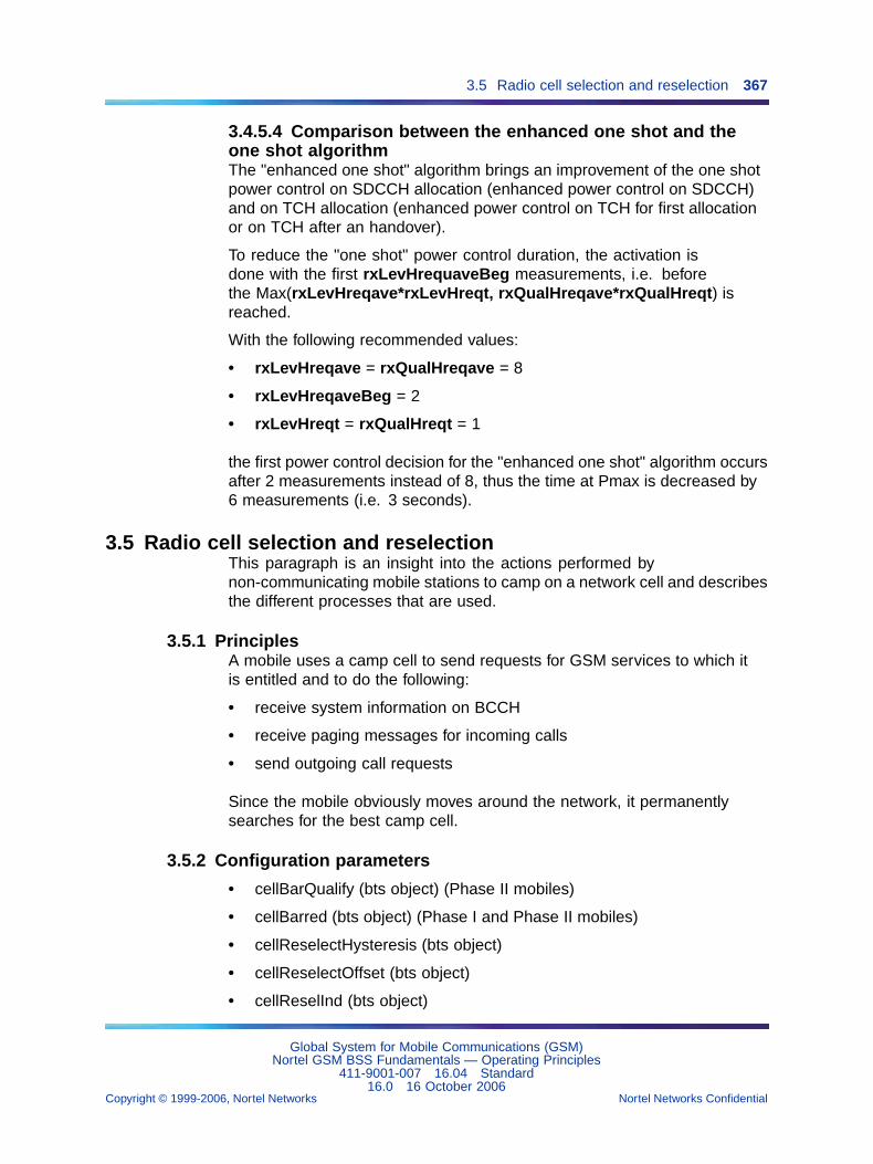
3.5 Radio cell selection and reselection 367
3.4.5.4 Comparison between the enhanced one shot and theone shot algorithmThe "enhanced one shot" algorithm brings an improvement of the one shotpower control on SDCCH allocation (enhanced power control on SDCCH)and on TCH allocation (enhanced power control on TCH for first allocationor on TCH after an handover).
To reduce the "one shot" power control duration, the activation isdone with the first rxLevHrequaveBeg measurements, i.e. beforethe Max(rxLevHreqave*rxLevHreqt, rxQualHreqave*rxQualHreqt) isreached.
With the following recommended values:
• rxLevHreqave = rxQualHreqave = 8
• rxLevHreqaveBeg = 2
• rxLevHreqt = rxQualHreqt = 1
the first power control decision for the "enhanced one shot" algorithm occursafter 2 measurements instead of 8, thus the time at Pmax is decreased by6 measurements (i.e. 3 seconds).
3.5 Radio cell selection and reselectionThis paragraph is an insight into the actions performed bynon-communicating mobile stations to camp on a network cell and describesthe different processes that are used.
3.5.1 PrinciplesA mobile uses a camp cell to send requests for GSM services to which itis entitled and to do the following:
• receive system information on BCCH
• receive paging messages for incoming calls
• send outgoing call requests
Since the mobile obviously moves around the network, it permanentlysearches for the best camp cell.
3.5.2 Configuration parameters
• cellBarQualify (bts object) (Phase II mobiles)
• cellBarred (bts object) (Phase I and Phase II mobiles)
• cellReselectHysteresis (bts object)
• cellReselectOffset (bts object)
• cellReselInd (bts object)
Global System for Mobile Communications (GSM)Nortel GSM BSS Fundamentals — Operating Principles
411-9001-007 16.04 Standard16.0 16 October 2006
Copyright © 1999-2006, Nortel Networks Nortel Networks Confidential
.
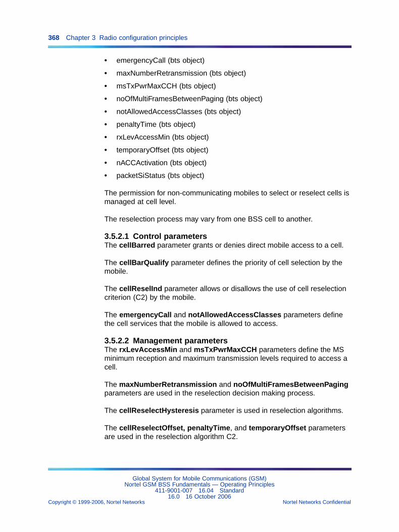
368 Chapter 3 Radio configuration principles
• emergencyCall (bts object)
• maxNumberRetransmission (bts object)
• msTxPwrMaxCCH (bts object)
• noOfMultiFramesBetweenPaging (bts object)
• notAllowedAccessClasses (bts object)
• penaltyTime (bts object)
• rxLevAccessMin (bts object)
• temporaryOffset (bts object)
• nACCActivation (bts object)
• packetSiStatus (bts object)
The permission for non-communicating mobiles to select or reselect cells ismanaged at cell level.
The reselection process may vary from one BSS cell to another.
3.5.2.1 Control parametersThe cellBarred parameter grants or denies direct mobile access to a cell.
The cellBarQualify parameter defines the priority of cell selection by themobile.
The cellReselInd parameter allows or disallows the use of cell reselectioncriterion (C2) by the mobile.
The emergencyCall and notAllowedAccessClasses parameters definethe cell services that the mobile is allowed to access.
3.5.2.2 Management parametersThe rxLevAccessMin and msTxPwrMaxCCH parameters define the MSminimum reception and maximum transmission levels required to access acell.
The maxNumberRetransmission and noOfMultiFramesBetweenPagingparameters are used in the reselection decision making process.
The cellReselectHysteresis parameter is used in reselection algorithms.
The cellReselectOffset, penaltyTime, and temporaryOffset parametersare used in the reselection algorithm C2.
Global System for Mobile Communications (GSM)Nortel GSM BSS Fundamentals — Operating Principles
411-9001-007 16.04 Standard16.0 16 October 2006
Copyright © 1999-2006, Nortel Networks Nortel Networks Confidential
.
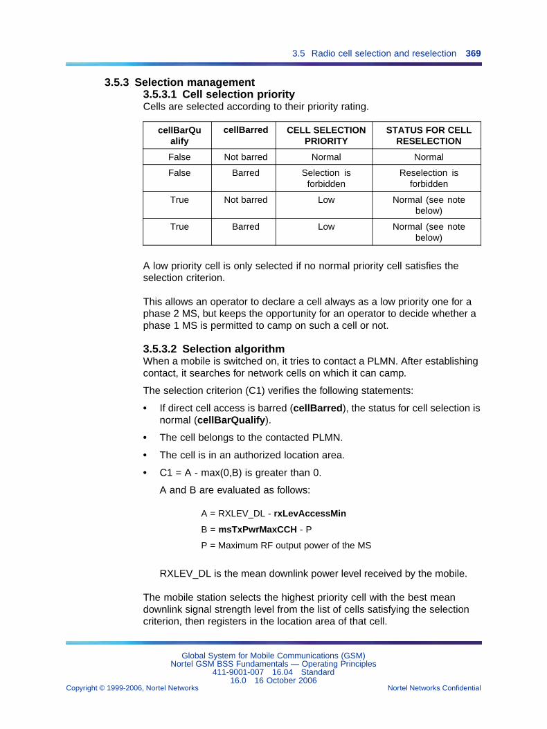
3.5 Radio cell selection and reselection 369
3.5.3 Selection management3.5.3.1 Cell selection priorityCells are selected according to their priority rating.
cellBarQualify
cellBarred CELL SELECTIONPRIORITY
STATUS FOR CELLRESELECTION
False Not barred Normal Normal
False Barred Selection isforbidden
Reselection isforbidden
True Not barred Low Normal (see notebelow)
True Barred Low Normal (see notebelow)
A low priority cell is only selected if no normal priority cell satisfies theselection criterion.
This allows an operator to declare a cell always as a low priority one for aphase 2 MS, but keeps the opportunity for an operator to decide whether aphase 1 MS is permitted to camp on such a cell or not.
3.5.3.2 Selection algorithmWhen a mobile is switched on, it tries to contact a PLMN. After establishingcontact, it searches for network cells on which it can camp.
The selection criterion (C1) verifies the following statements:
• If direct cell access is barred (cellBarred), the status for cell selection isnormal (cellBarQualify).
• The cell belongs to the contacted PLMN.
• The cell is in an authorized location area.
• C1 = A - max(0,B) is greater than 0.
A and B are evaluated as follows:
A = RXLEV_DL - rxLevAccessMin
B = msTxPwrMaxCCH - P
P = Maximum RF output power of the MS
RXLEV_DL is the mean downlink power level received by the mobile.
The mobile station selects the highest priority cell with the best meandownlink signal strength level from the list of cells satisfying the selectioncriterion, then registers in the location area of that cell.
Global System for Mobile Communications (GSM)Nortel GSM BSS Fundamentals — Operating Principles
411-9001-007 16.04 Standard16.0 16 October 2006
Copyright © 1999-2006, Nortel Networks Nortel Networks Confidential
.
370 Chapter 3 Radio configuration principles
The selected cell is then the mobile station’s camp cell.
3.5.3.3 NoteFor mobiles that can work in various frequency bands (they are calledmultiband mobiles), the operator can favor the selection of a cell thatbelongs to a frequency band other than the standard GSM band by settingthe cellBarQualify parameter of the cells in the GSM band to "true".
In that case, the only way to bar access to a cell in the GSM band is tomodify both the cellBarQualify and the cellBarred parameters.
3.5.4 Reselection managementA mobile may have to reselect a camp cell for a number of reasons:
• The mobile periodically searches for a better camp cell in the samePLMN and draws up the list of the best qualified cells to receive its calls.
• Direct access to the camp cell changes to barred or its selection prioritychanges from low to normal.
• The paging channel monitoring process for the current camp cell detectsabnormal downlink interference.
3.5.4.1 Reselection algorithm C1The reselection algorithm C1 ensures that the mobile is camping on the celloffering the best communication capabilities without interference. It is usedby Phase I and Phase II mobiles.
The reselection criterion (C1) verifies the following statements:
• If direct cell access is barred (cellBarred), the status for cell selection isnormal (cellBarQualify).
• The cell belongs to the same PLMN as the current camp cell.
• The cell is in an authorized location area.
• C1 = A - max(0,B) is greater than 0. The meaning of A and B is thesame as in the selection algorithm.
The mobile only qualifies the cells from those satisfying the reselectioncriterion where the value of C1 is greater than C1 in the current camp cell.
3.5.4.2 Reselection algorithm C2The reselection algorithm C2 ensures that the mobile is camping on the celloffering the best communication capabilities on both the downlink and theuplink. It is only used by Phase II mobiles.
The reselection criterion (C2) verifies the following statements:
• If direct cell access is barred (cellBarred), the status for cell selection isnormal (cellBarQualify).
Global System for Mobile Communications (GSM)Nortel GSM BSS Fundamentals — Operating Principles
411-9001-007 16.04 Standard16.0 16 October 2006
Copyright © 1999-2006, Nortel Networks Nortel Networks Confidential
.
3.5 Radio cell selection and reselection 371
• The use of the reselection criterion (C2) is allowed for the cell(cellReselInd).
• The cell belongs to the same PLMN as the current camp cell.
• The cell is in an authorized location area.
• C2 is greater than zero.
If penaltyTime = 640, then C2 = (C1 - Cr); otherwise, C2 = (C1 + Cr)
C1 = A - max(0,B), as before.
Cr = cellReselectOffset - (temporaryOffset × H(penaltyTime - T))
— T is a timer that is started when the mobile includes the cell in the listof best qualified cells to receive calls and is stopped when the cellis removed from the list.
— H( penaltyTime - T) equals 0 if penaltyTime < T and equals 1 ifpenaltyTime ≥ T.
Therefore, at a given time, Cr may be null, positive or negative.
The mobile only qualifies the cells from those satisfying the reselectioncriterion where the value of C2 is greater than the value of C1 in the currentcamp cell.
3.5.4.3 Decision makingQualified cells are listed in the descending order of their reselectionparameter value (C1 or C2).
The decision making algorithm is as follows:
• If the first cell in the list is in the same location area as the current campcell, this cell is selected and becomes the new camp cell for the mobile.
• If the first cell in the list is in a different location area than the currentcamp cell, the following apply:
— If its reselection parameter value is greater than the selectionparameter value C1 of the current camp cell by at leastcellReslectHysteresis dB, this cell is selected and becomes thenew camp cell for the mobile.
— If the previous criterion is not verified, the mobile searches in the listfor a qualified cell in the same location area and selects that cell asits new camp cell.
• If no cell in the list qualifies, the mobile starts the reselection processagain with new radio measurements.
The cellReslectHysteresis factor is used to prevent the mobile fromswitching back and forth from one location area to another.
Global System for Mobile Communications (GSM)Nortel GSM BSS Fundamentals — Operating Principles
411-9001-007 16.04 Standard16.0 16 October 2006
Copyright © 1999-2006, Nortel Networks Nortel Networks Confidential
.
372 Chapter 3 Radio configuration principles
3.5.4.4 Notes
• If a mobile cannot find a new camp cell or receives an "Illegal MS"response to a location update request from the camp cell, it tries tocamp on a cell regardless of the contacted PLMN identifier but itsservice state is restricted to emergency calls.
• Mobiles can still access a cell where direct access is barred providedincoming handovers are allowed in that cell (incomingHandOverattribute).
• For mobiles that can work in various frequency bands (they are calledmultiband mobiles), the operator can favor the reselection of a cell thatbelongs to another frequency band by giving different values to thecellReselectOffset parameters in the cells of each frequency band.
• When a mobile starts communicating, the serving cell that will be usedduring the call is selected by the BSC according to the results of theradio measurement processing performed by the BTS.
3.5.5 Network assisted cell change for release 4 MSNetwork Assisted Cell Change (NACC) for release 4 MS enables thenetwork to assist the MS for cell reselection during on-going TBF.
By reducing the duration of cell reselection, NACC improves the end-userthroughput when the MS is moving from one cell to another.
The feature can be activated on a per cell basis. The feature is limited tointra-BSC cell re-selection. It does not impact the core network.
The feature does not affect the behavior of pre-release 4 MSs. A pre-release4 MS will not benefit from the NACC feature, and its reselection time willnot be modified by NACC activation.
The NACC feature is divided into 2 sub-features:
1. The indication of the reselection and the first SI download in the initialcell (CCN).
2. The acquisition of the missing SI in the target cell (SI Status).
These sub-features are enabled/disabled by the bts parametersnACCActivation and packetSiStatus, respectively. The sub-features canbe activated independently, but both contribute to the reduction of the cellreselection duration.
3.6 Handover management3.6.1 Principles
3.6.1.1 Definition of a handoverA handover designs the process of call sustaining while the mobile stationis moving from one serving cell to another one.
Global System for Mobile Communications (GSM)Nortel GSM BSS Fundamentals — Operating Principles
411-9001-007 16.04 Standard16.0 16 October 2006
Copyright © 1999-2006, Nortel Networks Nortel Networks Confidential
.
3.6 Handover management 373
The main purpose of handovers is to avoid losing a call in progress.
Handover management is based on:
• the results of downlink measurements performed by mobile stations
• uplink measurements performed by the BTS
• the currently user defined values of super-average computing anddecision making parameters in the OMC-R (see Section 3.6.2"Configuration parameters" (page 377))
A handover is carried out in four steps:
1) Triggering: the BTS detects that a handover is needed (comparisonwith thresholds)
2) Screening: in the BTS, the L1M (layer one management software)determines what are the three best suitable target cells for the handover(from the preferred cells list), and sends them to the BSC in the HANDOVERINDICATION message.
3) Selecting: in the BSC, the TMG (traffic management software)determines the target cell according to the resource found.
4) Executing: Assignment of the new channel by the TMG, allocation andactivation, then switching onto this channel.
Handovers involving concentric cells (see Section 3.6.4 "Concentric cells"(page 389)), neighbor cells (see Section 3.6.5 "Neighbor cells" (page392)), and microcells (see Section 3.6.6 "Microcells" (page 398)) aredescribed too.
In V14 release a new handover is introduced. This handover is a classichandover complement which is called Handover adaptation.
3.6.1.2 handover adaptationThis feature (TD1216: automatic handover adaptation) adapts handoverparameters to the radio environment of each call, taking into account bothmobile speed and frequency hopping.
The handover adaptation minimizes to call drop and bad qualitytransmission.
The handover adaptation provides a better network quality:
• In a rural environment by:
— reducing the time to decide to perform a PBGT handover, thusavoiding some handovers on alarm criteria.
Global System for Mobile Communications (GSM)Nortel GSM BSS Fundamentals — Operating Principles
411-9001-007 16.04 Standard16.0 16 October 2006
Copyright © 1999-2006, Nortel Networks Nortel Networks Confidential
.
374 Chapter 3 Radio configuration principles
• In an urban environment by:
— reducing the time to decide to perform a PBGT handover, andconsequently the network interference level
— reducing interference level due to better power control
— reducing the time to decide to increase the power level of a mobilewith interference.
The principle of this feature is to use these averages introduced by thefrequency hopping and the MS speed, in order to decrease the number ofmeasurements taken into account or handover margin.
Frequency hopping decision In order to have a sufficient averaging ofthe Rayleigh fading, the number of frequencies in the hopping law has to begreater than or equal to 8.
If the number of frequencies in the hopping law is less than 8, the mobilesare considered as non-hopping, and all defined processes for non hoppingmobiles are applied.
This decision and all associated mechanisms are applied to the followingchannels:
• TCH Full Rate whatever the channel coding (data circuit, EFR, FR,AMR...)
• TCH Half Rate
• SDCCH.
Mobile Station (MS) speed evaluator decision The standard deviationof Rxlev during one period of measurement (104 bursts, thus 480ms) isless than 1.4 dB.
The standard deviation represents approximately:
• 20 km/h in GSM900
• 10km/h in GSM 1800/GSM1900
This standard is sufficient to have a good average of Rayleigh fading.
Half Rate and SDCCH channels For half rate channels, the number ofburst during the period (one time slot) is sufficient to evaluate accurately thestandard deviation criteria. Then, all treatments associated to this criteriaare relevant for the kind of channel.
Global System for Mobile Communications (GSM)Nortel GSM BSS Fundamentals — Operating Principles
411-9001-007 16.04 Standard16.0 16 October 2006
Copyright © 1999-2006, Nortel Networks Nortel Networks Confidential
.
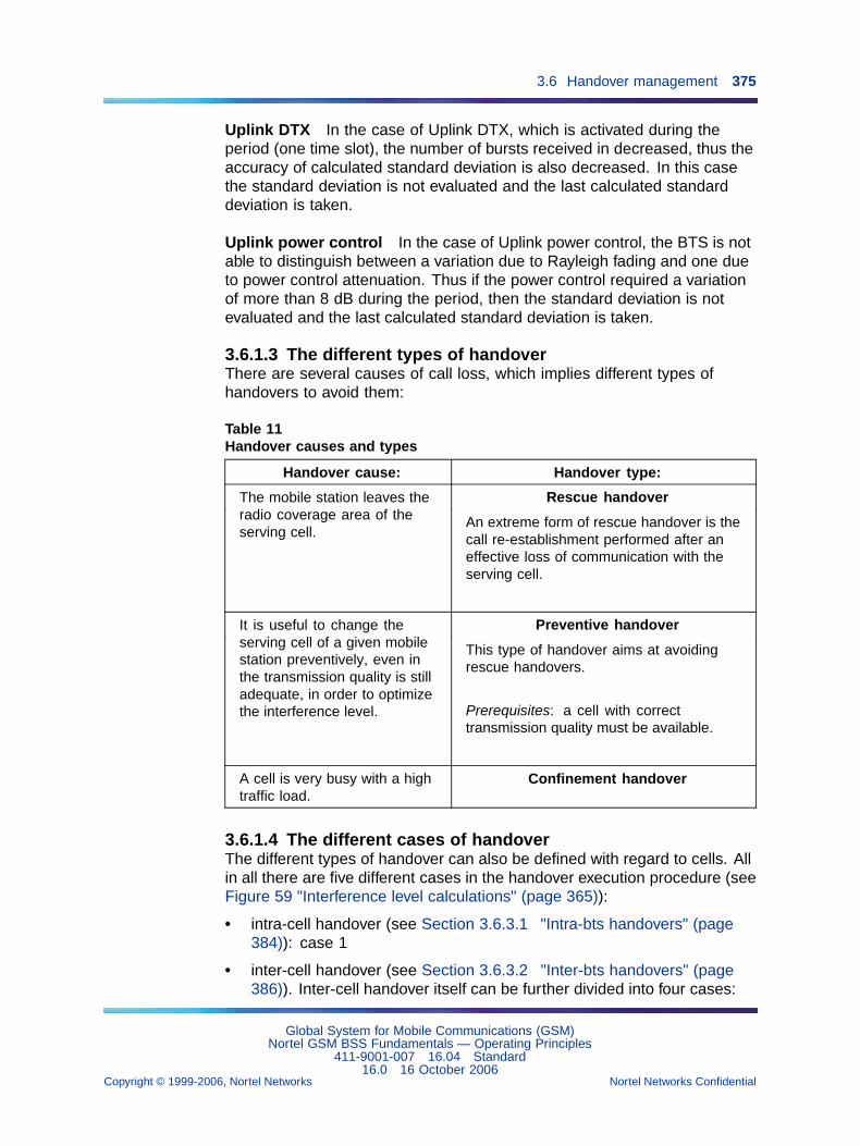
3.6 Handover management 375
Uplink DTX In the case of Uplink DTX, which is activated during theperiod (one time slot), the number of bursts received in decreased, thus theaccuracy of calculated standard deviation is also decreased. In this casethe standard deviation is not evaluated and the last calculated standarddeviation is taken.
Uplink power control In the case of Uplink power control, the BTS is notable to distinguish between a variation due to Rayleigh fading and one dueto power control attenuation. Thus if the power control required a variationof more than 8 dB during the period, then the standard deviation is notevaluated and the last calculated standard deviation is taken.
3.6.1.3 The different types of handoverThere are several causes of call loss, which implies different types ofhandovers to avoid them:
Table 11Handover causes and types
Handover cause: Handover type:
Rescue handoverThe mobile station leaves theradio coverage area of theserving cell.
An extreme form of rescue handover is thecall re-establishment performed after aneffective loss of communication with theserving cell.
Preventive handoverIt is useful to change theserving cell of a given mobilestation preventively, even inthe transmission quality is stilladequate, in order to optimizethe interference level.
This type of handover aims at avoidingrescue handovers.
Prerequisites: a cell with correcttransmission quality must be available.
A cell is very busy with a hightraffic load.
Confinement handover
3.6.1.4 The different cases of handoverThe different types of handover can also be defined with regard to cells. Allin all there are five different cases in the handover execution procedure (seeFigure 59 "Interference level calculations" (page 365)):
• intra-cell handover (see Section 3.6.3.1 "Intra-bts handovers" (page384)): case 1
• inter-cell handover (see Section 3.6.3.2 "Inter-bts handovers" (page386)). Inter-cell handover itself can be further divided into four cases:
Global System for Mobile Communications (GSM)Nortel GSM BSS Fundamentals — Operating Principles
411-9001-007 16.04 Standard16.0 16 October 2006
Copyright © 1999-2006, Nortel Networks Nortel Networks Confidential
.
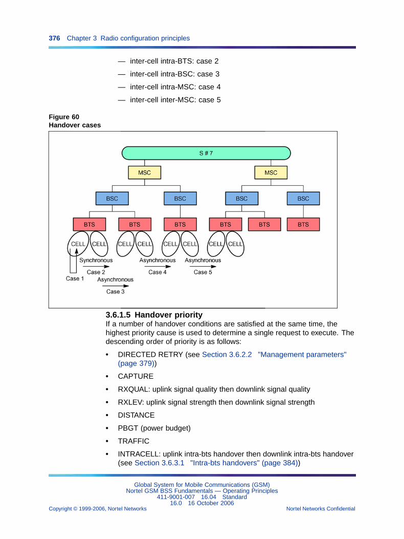
376 Chapter 3 Radio configuration principles
— inter-cell intra-BTS: case 2
— inter-cell intra-BSC: case 3
— inter-cell intra-MSC: case 4
— inter-cell inter-MSC: case 5
Figure 60Handover cases
3.6.1.5 Handover priorityIf a number of handover conditions are satisfied at the same time, thehighest priority cause is used to determine a single request to execute. Thedescending order of priority is as follows:
• DIRECTED RETRY (see Section 3.6.2.2 "Management parameters"(page 379))
• CAPTURE
• RXQUAL: uplink signal quality then downlink signal quality
• RXLEV: uplink signal strength then downlink signal strength
• DISTANCE
• PBGT (power budget)
• TRAFFIC
• INTRACELL: uplink intra-bts handover then downlink intra-bts handover(see Section 3.6.3.1 "Intra-bts handovers" (page 384))
Global System for Mobile Communications (GSM)Nortel GSM BSS Fundamentals — Operating Principles
411-9001-007 16.04 Standard16.0 16 October 2006
Copyright © 1999-2006, Nortel Networks Nortel Networks Confidential
.
3.6 Handover management 377
• INTERBAND handover for dualband cell, INTERZONE for concentriccell and dualcoupling cell
• FREQUENCY TIERING (see page 2-52)
In V14 feature, this functionality in not modified for mobiles, but for AMRmobiles, it becomes the following order:
• AMR quality: uplink then downlink
• DISTANCE
• PBGT (power budget)
• TRAFFIC
• INTER-MODE (HR -> FR)
• INTRACELL: uplink intra-bts handover then downlink intra-bts handover(see Section 3.6.3.1 "Intra-bts handovers" (page 384))
• INTERBAND handover for dualband cell, INTERZONE for concentriccell and dualcoupling cell
• FREQUENCY TIERING (see page 3-61)
3.6.2 Configuration parameters
• adjacent cell umbrella Ref (bts object)
• biZonePowerOffset (handOverControl object)
• bssMapTchoke (bsc object)
• bts time between HO configuration (bts object)
• btsReserved3 (bts object)
• concentAlgoExtMsRange (handOverControl object) (concentric cell)
• concentAlgoExtRxLev (handOverControl object) (concentric cell)
• concentAlgoIntMsRange (handOverControl object) (concentric cell)
• concentAlgoIntRxLev (handOverControl object) (concentric cell)
• directedRetry (adjacentCellHandOver object)
• directedRetryModeUsed (bts object)
• forced handover algo (adjacentCellHandOver object)
• HandOver from signalling channel (bts object)
• hoMargin (adjacentCellHandOver object)
• hoMarginBeg (bts)
• hoMarginDist (adjacentCellHandOver object)
Global System for Mobile Communications (GSM)Nortel GSM BSS Fundamentals — Operating Principles
411-9001-007 16.04 Standard16.0 16 October 2006
Copyright © 1999-2006, Nortel Networks Nortel Networks Confidential
.
378 Chapter 3 Radio configuration principles
• hoMarginRxLev (adjacentCellHandOver object)
• hoMarginRxQual (adjacentCellHandOver object)
• hoMarginTiering (handOverControl object)
• HOSecondBestCellConfiguration (bsc object)
• incomingHandOver (handOverControl object)
• interBscDirectedRetry (bsc object) interBscDirectedRetryFromCell (btsobject)
• interferenceType (adjacentCellHandOver object)
• intraBscDirectedRetry (bsc object)
• intraBscDirectedRetryFromCell (bts object)
• intraCell (handOverControl object)
• intraCellSDCCH (handOverControl object)
• lRxLevDLH (handOverControl object)
• lRxLevULH (handOverControl object)
• lRxQualDLH (handOverControl object)
• lRxQualULH (handOverControl object)
• measurementProcAlgorithm (bts object)
• microCellCaptureTimer (adjacentCellHandOver object - A algorithm)
• microCellInstabilityTimer (bts object - B algorithm)
• microCellStability (adjacentCellHandOver object - A algorithm)
• microCellStability (bts object - B algorithm)
• msBtsDistanceInterCell (handOverControl object)
• msRangeMax (handOverControl object)
• msTxPwrMaxCell (adjacentCellHandOver object) numberOfPwciSam-ples (handOverControl object)
• plmnPermitted (bts object)
• powerBudgetInterCell (handOverControl object)
• pwciHreqave (handOverControl object)
• radChanSelIntThreshold (handOverControl object)
• runHandOver (bts object)
• rxLevDLPBGT (adjacentCellHandOver)
• rxLevDLIH (handOverControl object)
Global System for Mobile Communications (GSM)Nortel GSM BSS Fundamentals — Operating Principles
411-9001-007 16.04 Standard16.0 16 October 2006
Copyright © 1999-2006, Nortel Networks Nortel Networks Confidential
.
3.6 Handover management 379
• rxLevMinCell (adjacentCellHandOver object)
• rxLevULIH (handOverControl object)
• rxQualDLIH (handOverControl object)
• rxQualULIH (handOverControl object)
• selfTuningObs (handOverControl object)
• thresholdInterference (handOverControl object)
• timeBetweenHOConfiguration (bsc object)
For more information on these parameters, refer to (NTP < 124 >).
3.6.2.1 Control parametersVarious types of handovers can be authorized or forbidden in a servingcell, such as:
• incoming handovers (incomingHandOver)
• intra-bts handovers on TCH (intraCell) or on SDCCH (intraCellSDCCH)
• inter-bts handovers for distance reasons (msBtsDistanceInterCell) orpower budget reasons (powerBudgetInterCell)
• handovers in signalling mode (HandOver from signalling channel)
Super-averaging results verify whether or not the conditions for intra-btshandover or inter-bts handover to a neighbor cell are satisfied.
3.6.2.2 Management parametersThe following thresholds are defined independently on the downlink andthe uplink:
• signal strength level thresholds (lRxLevDLH and lRxLevULH)
• quality level thresholds (lRxQualDLH, lRxQualULH, rxQualDLIH, andrxQualULIH)
• interference thresholds (rxLevDLIH and rxLevULIH)
The HOSecondBestCellConfiguration parameter allows the BSC toattempt immediate handover to another cell if the first attempt fails withMS going back to the old channel.
The V10+ rxLevDLPBGT parameter enables to prevent handovers (in issuesuch as street corner) for power budget reason. If the downlink signalstrength in serving cell exceeds this threshold, handover is not allowed.This value is set such as serving cell received level (above this threshold) inthe serving cell is good enough and a handover for power budget reasonwould not improve the situation.
Global System for Mobile Communications (GSM)Nortel GSM BSS Fundamentals — Operating Principles
411-9001-007 16.04 Standard16.0 16 October 2006
Copyright © 1999-2006, Nortel Networks Nortel Networks Confidential
.
380 Chapter 3 Radio configuration principles
Intra- and inter-bss handovers The plmnPermitted parameter definesthe PLMNs where the mobile stations camped in a cell are permitted toperform measurements for handover purposes.
Directed retry handovers When the MSC executes an assign procedure,the BSC may be allowed to direct neighbor cell selection if the serving cellhas no available TCH resources.
The xxxDirectedRetry parameters define the conditions in which directedretry handovers are legitimate. The directed retry algorithm is not startedfor a serving cell unless directed retry handovers are allowed both in theBSC and the cell.
The directedRetryModeUsed parameter defines whether directed retryhandover processing is controlled by the BSC or the BTS. BSC processing isallowed only for serving microcells and, in that case, the BSC directly selectsthe neighbor umbrella cell chosen by the user (adjacent cell umbrella Ref).
The Queueing feature must be activated.
Forced handovers A forced handover is a user action aimed at forcingthe BSC to redirect all ongoing calls in a serving cell to its neighbor cells.
The forced handover algo parameter defines access conditions to aneighbor cell for processing these handovers.
Frequency tiering
Definition The frequency tiering technique aims at allocating resourcesduring a handover, by taking into account the criterion representing thepotential interference that could be experienced by the call (Feature TF995 -Automatic Cell Tiering).
Thus it aims at decreasing the global interference level in a fractional reusepattern network. (Fractional reuse is an optimized frequency hoppingfeature, in which TCH TRX/DRXs hop on a large set of frequencies. EachBTS is allocated a number of frequencies which is superior to the numberof TRX/DRXs. Thus each TRX/DRX hops on a large set of frequencies,lowering the probability of collisions between inter-site timeslots).
The frequency tiering technique allocates the worst communications(in terms of downlink CIR (Carrier on Interference Ratio)) to the BCCHfrequencies, taking advantage of their larger reuse pattern and consequentlyof their better resistance to interference.
The frequency tiering technique uses the BTS self-tuning functionality. Thisfunctionality enables the BTS to determine the most appropriate thresholdvalues for the tiering handover algorithm, since they are dynamically adapted
Global System for Mobile Communications (GSM)Nortel GSM BSS Fundamentals — Operating Principles
411-9001-007 16.04 Standard16.0 16 October 2006
Copyright © 1999-2006, Nortel Networks Nortel Networks Confidential
.
3.6 Handover management 381
to O&M events and to radio environment modifications. The BTS self-tuningfunctionality uses the radio-electrical profile of the cell, established bygathering and processing radio link measurements at cell level. The cellprofile enables to obtain PwCIDLH and uPwCIDLH tiering threshold values:
• The lPwCIDLH tiering threshold is the threshold to handover from thesmall (TCH) pattern to the large (BCCH) pattern.
• The uPwCIDLH tiering threshold is the threshold to handover from thelarge (BCCH) pattern to the small (TCH) pattern.
The relation is: uPwCIDLH = lPwCIDLH + hoMarginTiering
The hoMarginTiering parameter is the hysteresis between the uPwCIDLHand lPwCIDLH tiering thresholds, to avoid ping-pong handovers.
Prerequisites
• The whole network must have been upgraded to v12.4 system release.
• The frequency tiering technique is available on the following BSSsub-systems:
— S8000 BTS
— S2000 H/L BTS
— e-cell BTS
• BTSs must use the V2 release of the L1M software.
The measurementProcAlgorithm parameter defines the L1M softwareversion used by each BTS, and it must be set to "L1MV2".
Restrictions Frequency tiering handovers are not applicable to GPRSsince GPRS channels are not TCH resources but pDTCH resources.
Activation of the frequency tiering feature Intracell handovers that areperformed for signal quality/strength and those performed for tiering reasonsare mutually exclusive. To activate the tiering handover decision function atthe BTS level, the intracell parameter must be set to "cellTieringHandOver".
PwCI computation The tiering decision relies on a CIR estimate whichuses signal strength measurements (Rx_LEV_DL and Rx_LEV_NCell(n))performed by the mobile station on the BCCH of neighbor cells. Thisestimate gives a Potential Worst case value of the real CIR (PwCI), in thefollowing cases:
• when all interferers transmit at maximum transmission power
• when the interference is either a co-channel interference or aninterference between first adjacent cells. The interferenceType
Global System for Mobile Communications (GSM)Nortel GSM BSS Fundamentals — Operating Principles
411-9001-007 16.04 Standard16.0 16 October 2006
Copyright © 1999-2006, Nortel Networks Nortel Networks Confidential
.
382 Chapter 3 Radio configuration principles
parameter is defined for the adjacentCellHandOver object and itindicates the type of interference created by neighbor cell.
• when the network is fully loaded (all neighbor cells using the same TCHfrequency set create co-channel interferences)
The practical range of values of PwCI is [-40dB ; +50dB], and its computationis valid for reuse patterns from 1x1 to 1x3 only.
The selfTuningObs parameter indicates whether or not the PwCIdistribution is sent to the Abis interface periodically by the BTS, in a specificevent report message, in order to limit the load on the BSC-OMC-R interface.
The PwCI distribution is sent when one of the following events occurs:
• reliable statistics have been obtained for the first time (at leastnumberOfPwciSamples PwCI values have been gathered)
• reliable statistics exist and at least (numberOfPwciSampl es /2)additional PwCI values have been gathered
• the BCCH/TCH resources ratio has changed (a TDMA has been lost orhas been retrieved)
The numberOfPwciSamples parameter indicates the minimal number ofPwCI samples gathered by the BTS, and required to compute a reliabletiering threshold.
The PwCI is averaged for tiering decisions. The averaging window size usedfor PwCI is defined by the PwciHreqave parameter.
Tiering handover decision by the BTS PwCI is constantly monitoredby the BTS for each TCH channel. The tiering decision is taken by theBTS only when a reliable threshold has been obtained from the statisticsgathered by the BTS.
• 1st case: the TDMA bearing the channel belongs to the small (TCH)pattern. Besides, it does not belong to the "small zone" of a multizonecell.
— If PwCI < lPwCIDLH, then the traffic channel must be put on thelarge BCCH frequency reuse pattern (if possible).
— So the BTS sends a HANDOVER INDICATION message, with"Frequency tiering" as a cause, to the BSC.
— Then the counter C1138/16 hoRequiredTchTieringSmallToLargePat-tern is updated.
• 2nd case: the TDMA bearing the channel belongs to the large (BCCH)pattern. Besides, it belongs to the "large zone" of a multizone cell.
Global System for Mobile Communications (GSM)Nortel GSM BSS Fundamentals — Operating Principles
411-9001-007 16.04 Standard16.0 16 October 2006
Copyright © 1999-2006, Nortel Networks Nortel Networks Confidential
.
3.6 Handover management 383
— If PwCI > uPwCIDLH, then the traffic channel must be put on thesmall TCH frequency reuse pattern (if possible).
— So the BTS sends a HANDOVER INDICATION message, with"Frequency tiering" as a cause, to the BSC.
— Then the counter C1138/15 hoRequiredTchTieringLargeToSmall-Pattern is updated.
The BTS repeats the HANDOVER INDICATION message, with "Frequencytiering" as a cause, as long as the tiering condition is fulfilled.
Resource allocation by the BSC When receiving a HANDOVERINDICATION message with "Frequency tiering" as a cause, the BSC:
• either allocates a channel belonging to a large pattern TDMA(BCCH or non hopping) if the current channel belongs to aTDMA within the small pattern. Then the counter C1802/1hoSuccessTieringTchSmallToLargePattern is updated.
• or allocates a channel belonging to a small pattern TDMA(TCH and hopping) if the current channel belongs to aTDMA within the large pattern. Then the counter C1802/0hoSuccessTieringTchLargeToSmallPattern is updated.
If no channel is available in the target pool, no queuing is applied. Thehandover indication is ignored and the relevant counter is updated:
• either C1801/0 hoFailureTieringTchNorrLargeToSmallPattern
• or C1801/1 hoFailureTieringTchNorrSmallToLargePattern
For more information on these counters, refer to NTP < 125 > .
The nbLargeReuseDataChannels parameter gives the mean number ofradio timeslots in the large (BCCH) reuse pattern which is used for datacommunications (and which is consequently not available for tiering). Ithas been introduced to allow a correct interworking between data andfrequency tiering. Data communications are known to be more sensitive tointerferences, and as a consequence they are preferably put on the large(BCCH) reuse pattern.
3.6.3 Processing algorithmsHandovers are managed at cell level. Therefore, the algorithm used tocompute super-averages and make handover decisions may vary from oneBSS cell to another.
The same algorithm is used for both directions. Decision making dependson the defined threshold values for each direction.
Global System for Mobile Communications (GSM)Nortel GSM BSS Fundamentals — Operating Principles
411-9001-007 16.04 Standard16.0 16 October 2006
Copyright © 1999-2006, Nortel Networks Nortel Networks Confidential
.
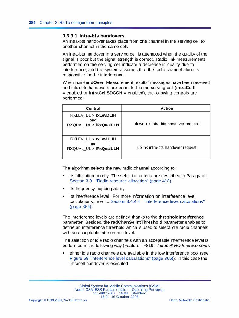
384 Chapter 3 Radio configuration principles
3.6.3.1 Intra-bts handoversAn intra-bts handover takes place from one channel in the serving cell toanother channel in the same cell.
An intra-bts handover in a serving cell is attempted when the quality of thesignal is poor but the signal strength is correct. Radio link measurementsperformed on the serving cell indicate a decrease in quality due tointerference, and the system assumes that the radio channel alone isresponsible for the interference.
When runHandOver "Measurement results" messages have been receivedand intra-bts handovers are permitted in the serving cell (intraCe ll= enabled or intraCellSDCCH = enabled), the following controls areperformed:
Control Action
RXLEV_DL > rxLevDLIHand
RXQUAL_DL > lRxQualDLH downlink intra-bts handover request
RXLEV_UL > rxLevULIHand
RXQUAL_UL > lRxQualULH uplink intra-bts handover request
The algorithm selects the new radio channel according to:
• its allocation priority. The selection criteria are described in ParagraphSection 3.9 "Radio resource allocation" (page 418).
• its frequency hopping ability
• its interference level. For more information on interference levelcalculations, refer to Section 3.4.4.4 "Interference level calculations"(page 364).
The interference levels are defined thanks to the thresholdInterferenceparameter. Besides, the radChanSelIntThreshold parameter enables todefine an interference threshold which is used to select idle radio channelswith an acceptable interference level.
The selection of idle radio channels with an acceptable interference level isperformed in the following way (Feature TF819 - Intracell HO Improvement):
• either idle radio channels are available in the low interference pool (seeFigure 59 "Interference level calculations" (page 365)): in this case theintracell handover is executed
Global System for Mobile Communications (GSM)Nortel GSM BSS Fundamentals — Operating Principles
411-9001-007 16.04 Standard16.0 16 October 2006
Copyright © 1999-2006, Nortel Networks Nortel Networks Confidential
.
3.6 Handover management 385
• or the low level interference pool is empty (because there are idle radiochannel only in the high level interference pool, or because there arenot any idle radio channels at all). In this case the intracell handoverrequest is:
— either rejected, because queuing intracell handover requests is notallowed
— or queued, because queuing intracell handover requests is allowed.However, deactivating the intracell handover request queueing ishighly recommended and sometimes mandatory (see Section 3.9.4"Queuing management" (page 419)).
This selection criterion is not applied for intracell handover due to TDMAremoval, and for interzone handover.
Starting with the V14 release, the intracell handover principle is an improvedmethod of reducing interference for the mobile. This principle is applicableonly to FR AMR mobiles, due to interactions with HR to FR handovers. Inthese situations, it is more efficient to allocate a FR radio TS to an HR AMRmobile, than to perform a handover from an HR TS to a FR TS.
The following parameter is introduced on handoverConrol object, in order tospecify the target requested codec mode for FR AMR channel:
• AMRFRIntracellCodecModeThreshold
The intra-cell handover (that is say intra-bts handover) includes the feature"TF1217 - protection against intra-cell handover (HO) ping-pong".
Protection against intra-cell handover This feature provides two kindsof intra-cell handover in terms of capacity and quality:
• The capacity intra-cell handover
The capacity intra-cell handover groups all intra-cell handovers whichare triggered in order to increase the network capacity.
It affects the following:
— inter-zone handover from the outer to the inner zone
— AMR handover from FR to HR TCH
— tiering from BCCH to TCH frequency patterns.
• The quality intra-cell handover
The quality intra-cell handover groups all intra-cell handover, which aretriggered if the quality of the call is not sufficient.
It affects the following:
— inter-zone handover from the inner to the outer zone
Global System for Mobile Communications (GSM)Nortel GSM BSS Fundamentals — Operating Principles
411-9001-007 16.04 Standard16.0 16 October 2006
Copyright © 1999-2006, Nortel Networks Nortel Networks Confidential
.
386 Chapter 3 Radio configuration principles
— AMR handover from HR to FR TCH
— tiering from TCH to BCCH frequency pattern
— normal intra-cell handover
The "protection against intra-cell handover ping-pong" is to introduce twotimers associated to the intra-cell handover type, which delay an otherintra-cell handover after an intra-cell handover.
It affects the following parameters which are included in the handoverControlobject:
• capacityTimeRejection
this parameter defines the rejection time of the capacity intra-cellhandover after an intra-cell handover.
• minTimeQualityIntraCellHO
this parameter defines the defines the minimum time between oneintracell HO and the next quality intracell HO
To avoid loads, filtering is done at the BTS level, thus at the L1m (Layer 1management) for the dedicated channel, the BSC specifies the followingcauses:
• initial assignment
• capacity intra-cell handover
• quality intra-cell handover
• inter-cell handover
Due to the following handover priorities:
• RXQUAL (Received signal Quality)
• RXLEV (Received signal Level)
• PBGT (Power Budget)
• TRAFFIC
• INTRA-CELL
• AMR INTRA-CELL and INTER-ZONE
The BTS checks if a cause of lower priority is fulfilled. It sends the numberof each kinds of filtered intra-cell handovers to the BSC.
3.6.3.2 Inter-bts handoversAn inter-cell handover takes place from a serving cell to an adjacent cell.
Global System for Mobile Communications (GSM)Nortel GSM BSS Fundamentals — Operating Principles
411-9001-007 16.04 Standard16.0 16 October 2006
Copyright © 1999-2006, Nortel Networks Nortel Networks Confidential
.
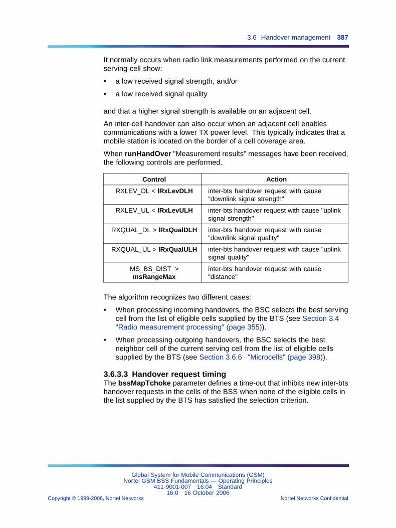
3.6 Handover management 387
It normally occurs when radio link measurements performed on the currentserving cell show:
• a low received signal strength, and/or
• a low received signal quality
and that a higher signal strength is available on an adjacent cell.
An inter-cell handover can also occur when an adjacent cell enablescommunications with a lower TX power level. This typically indicates that amobile station is located on the border of a cell coverage area.
When runHandOver "Measurement results" messages have been received,the following controls are performed.
Control Action
RXLEV_DL < lRxLevDLH inter-bts handover request with cause"downlink signal strength"
RXLEV_UL < lRxLevULH inter-bts handover request with cause "uplinksignal strength"
RXQUAL_DL > lRxQualDLH inter-bts handover request with cause"downlink signal quality"
RXQUAL_UL > lRxQualULH inter-bts handover request with cause "uplinksignal quality"
MS_BS_DIST >msRangeMax
inter-bts handover request with cause"distance"
The algorithm recognizes two different cases:
• When processing incoming handovers, the BSC selects the best servingcell from the list of eligible cells supplied by the BTS (see Section 3.4"Radio measurement processing" (page 355)).
• When processing outgoing handovers, the BSC selects the bestneighbor cell of the current serving cell from the list of eligible cellssupplied by the BTS (see Section 3.6.6 "Microcells" (page 398)).
3.6.3.3 Handover request timingThe bssMapTchoke parameter defines a time-out that inhibits new inter-btshandover requests in the cells of the BSS when none of the eligible cells inthe list supplied by the BTS has satisfied the selection criterion.
Global System for Mobile Communications (GSM)Nortel GSM BSS Fundamentals — Operating Principles
411-9001-007 16.04 Standard16.0 16 October 2006
Copyright © 1999-2006, Nortel Networks Nortel Networks Confidential
.
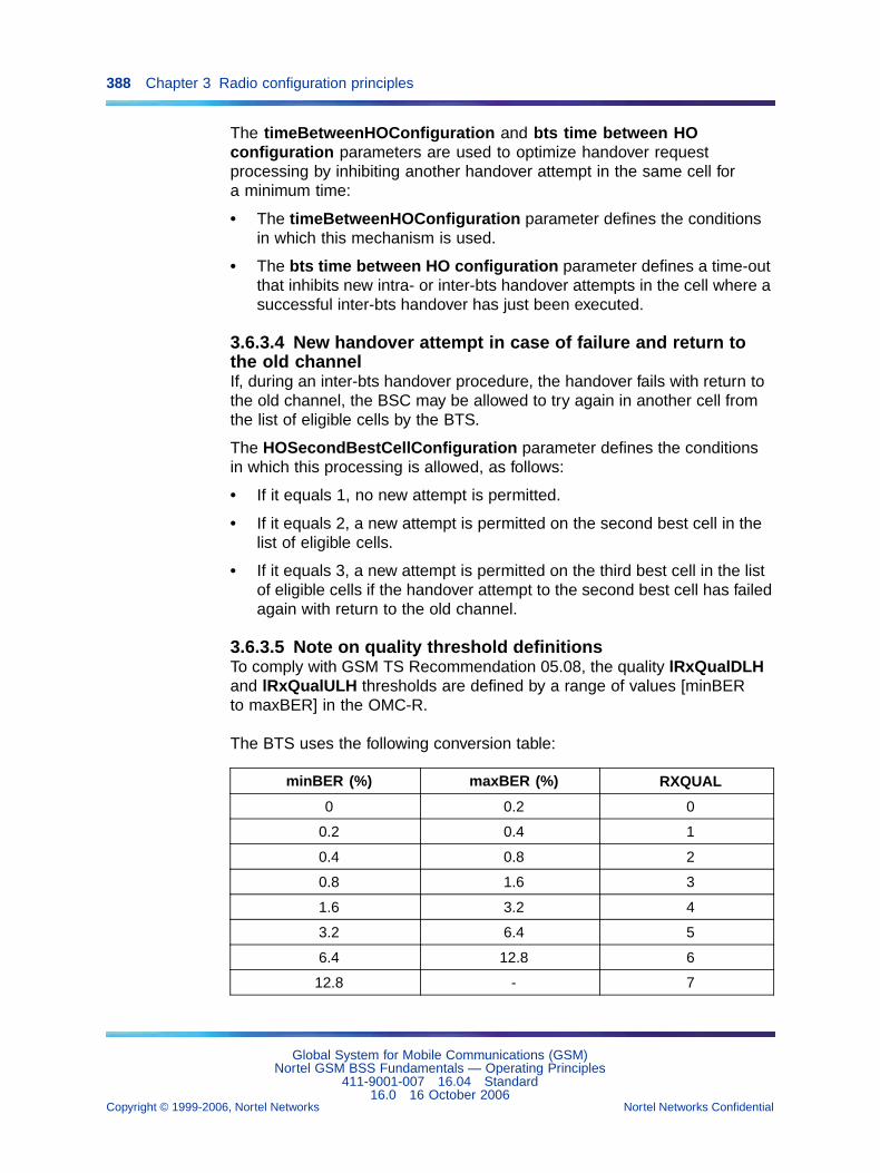
388 Chapter 3 Radio configuration principles
The timeBetweenHOConfiguration and bts time between HOconfiguration parameters are used to optimize handover requestprocessing by inhibiting another handover attempt in the same cell fora minimum time:
• The timeBetweenHOConfiguration parameter defines the conditionsin which this mechanism is used.
• The bts time between HO configuration parameter defines a time-outthat inhibits new intra- or inter-bts handover attempts in the cell where asuccessful inter-bts handover has just been executed.
3.6.3.4 New handover attempt in case of failure and return tothe old channelIf, during an inter-bts handover procedure, the handover fails with return tothe old channel, the BSC may be allowed to try again in another cell fromthe list of eligible cells by the BTS.
The HOSecondBestCellConfiguration parameter defines the conditionsin which this processing is allowed, as follows:
• If it equals 1, no new attempt is permitted.
• If it equals 2, a new attempt is permitted on the second best cell in thelist of eligible cells.
• If it equals 3, a new attempt is permitted on the third best cell in the listof eligible cells if the handover attempt to the second best cell has failedagain with return to the old channel.
3.6.3.5 Note on quality threshold definitionsTo comply with GSM TS Recommendation 05.08, the quality lRxQualDLHand lRxQualULH thresholds are defined by a range of values [minBERto maxBER] in the OMC-R.
The BTS uses the following conversion table:
minBER (%) maxBER (%) RXQUAL
0 0.2 0
0.2 0.4 1
0.4 0.8 2
0.8 1.6 3
1.6 3.2 4
3.2 6.4 5
6.4 12.8 6
12.8 - 7
Global System for Mobile Communications (GSM)Nortel GSM BSS Fundamentals — Operating Principles
411-9001-007 16.04 Standard16.0 16 October 2006
Copyright © 1999-2006, Nortel Networks Nortel Networks Confidential
.
3.6 Handover management 389
In all checks where "greater than" is used, the BTS selects the maxBERvalue.
In all checks where "smaller than" is used, the BTS selects the minBERvalue.
3.6.4 Concentric cells3.6.4.1 PrinciplesA concentric cell describes a combination of two transmission zones, theouter (or large) zone and the inner (or small) zone.
The TDMA frames used by a concentric cell are shared between the outerzone and the inner zone. The difference between the TRX/DRXs in eachzone is based on the maximum allowed transmission power.
Handover management principles in concentric cells are as follows:
• Since all the common channels, including the BCCH, are carried onTDMA frames that belong to the outer zone, an incoming handover to aconcentric cell can:
— either call on resources assigned to the outer zone
— or call on resources assigned to the inner zone (Direct TCHallocation in the small zone - Feature TF889)
• An intra-zone handover in a concentric cell is managed in the sameway as an intra-bts handover in a non-concentric cell. It only calls onthe radio resources in one zone, which means that the newly assignedradio resource always belongs to the same zone as the radio resourcethat is released.
• An inter-zone handover in a concentric cell is managed as a special sortof intra-bts handover in which the BTS initiates the handover by sendinga request to the BSC. It calls on the radio resources in both zones,which means that if the radio resource to release belongs to one zone,the newly assigned radio resource always belong to the other zone.
The major difference therefore concerns inter-zone handover management.
In V14, inter-zone handover are not modified due to AMR servicesintroduction, except for quality handover from inner-zone to outer-zone.
For non ARM calls, if the inter-cell RxQual criterion is verified and noneighboring cell is eligible, then an inner to large zone handover is triggered.
For ARM call, if the inter-cell ARM quality criterion is verified and no cellneighboring cell is eligible, then a inner to large zone handover is triggeredand the target channel is always a FR channel
Global System for Mobile Communications (GSM)Nortel GSM BSS Fundamentals — Operating Principles
411-9001-007 16.04 Standard16.0 16 October 2006
Copyright © 1999-2006, Nortel Networks Nortel Networks Confidential
.
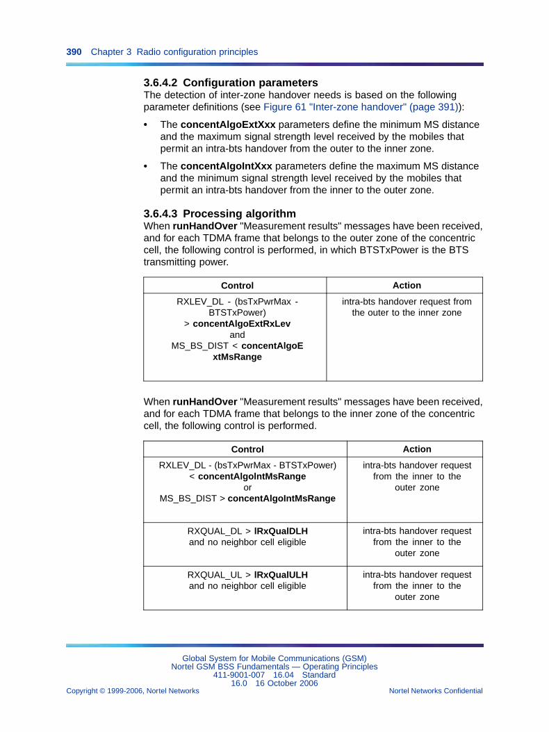
390 Chapter 3 Radio configuration principles
3.6.4.2 Configuration parametersThe detection of inter-zone handover needs is based on the followingparameter definitions (see Figure 61 "Inter-zone handover" (page 391)):
• The concentAlgoExtXxx parameters define the minimum MS distanceand the maximum signal strength level received by the mobiles thatpermit an intra-bts handover from the outer to the inner zone.
• The concentAlgoIntXxx parameters define the maximum MS distanceand the minimum signal strength level received by the mobiles thatpermit an intra-bts handover from the inner to the outer zone.
3.6.4.3 Processing algorithmWhen runHandOver "Measurement results" messages have been received,and for each TDMA frame that belongs to the outer zone of the concentriccell, the following control is performed, in which BTSTxPower is the BTStransmitting power.
Control Action
RXLEV_DL - (bsTxPwrMax -BTSTxPower)
> concentAlgoExtRxLevand
MS_BS_DIST < concentAlgoExtMsRange
intra-bts handover request fromthe outer to the inner zone
When runHandOver "Measurement results" messages have been received,and for each TDMA frame that belongs to the inner zone of the concentriccell, the following control is performed.
Control Action
RXLEV_DL - (bsTxPwrMax - BTSTxPower)< concentAlgolntMsRange
orMS_BS_DIST > concentAlgoIntMsRange
intra-bts handover requestfrom the inner to the
outer zone
RXQUAL_DL > lRxQualDLHand no neighbor cell eligible
intra-bts handover requestfrom the inner to the
outer zone
RXQUAL_UL > lRxQualULHand no neighbor cell eligible
intra-bts handover requestfrom the inner to the
outer zone
Global System for Mobile Communications (GSM)Nortel GSM BSS Fundamentals — Operating Principles
411-9001-007 16.04 Standard16.0 16 October 2006
Copyright © 1999-2006, Nortel Networks Nortel Networks Confidential
.
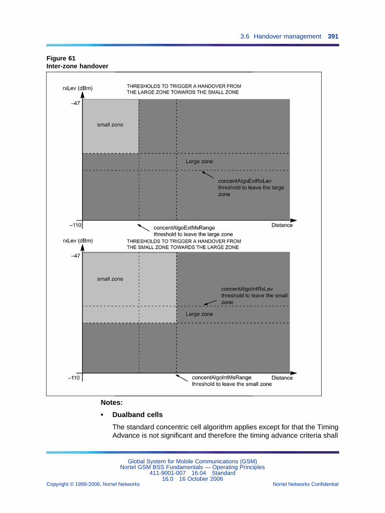
3.6 Handover management 391
Figure 61Inter-zone handover
Notes:
• Dualband cells
The standard concentric cell algorithm applies except for that the TimingAdvance is not significant and therefore the timing advance criteria shall
Global System for Mobile Communications (GSM)Nortel GSM BSS Fundamentals — Operating Principles
411-9001-007 16.04 Standard16.0 16 October 2006
Copyright © 1999-2006, Nortel Networks Nortel Networks Confidential
.
392 Chapter 3 Radio configuration principles
be disabled. Moreover the BSC knows MS dualband capability from MSClassmark 3 (CM3).
• Dualcoupling cells
The standard concentric cell algorithm applies except for that the TimingAdvance is not significant and therefore the timing advance criteria shallbe disabled.
3.6.5 Neighbor cellsOutgoing inter-bts handover management is based on the definition of theneighbor cells to which the BSC can request handovers when servingcell release conditions (signal strength, signal quality, and distance) aresatisfied.
The following cases are treated:
• outgoing inter-bts handover needs detected by the BTS
• directed retry handover requests sent by the BSC to the BTS
• forced handover requests sent by the BSC to the BTS
3.6.5.1 Configuration objectsThe adjacentcellHandOver objects attached to a bts object define theneighbor cells of the serving cell where outgoing inter-bts handovers can beperformed.
3.6.5.2 Processing algorithmsOutgoing inter-bts handovers detected by the BTS When the BTSdetects the need for an outgoing inter-bts handover, it draws up a list ofeligible neighbor cells that verify the formula
RXLEV_NCELL(n) > rxLevMinCell(n) + Mx
where Mx = max (0, msTxPwrMaxCell(n) - MSPowerMax)
Then, the BTS arranges the neighbor cells in the preferred order based onthe cause of the handover:
PBGT(n) > hoMargin(n) or
PBGT(n)>hoMarginBeg(n) ....... cause = power budget
PBGT(n) > hoMarginDist(n) ................ cause = distance
PBGT(n) > hoMarginRxLev(n) ............... cause = signal strength
PBGT(n) > hoMarginRxQual(n) ............. cause = quality
The BTS sends the information to the BSC when the list is complete.
Directed retry handovers requested by the BSC
Global System for Mobile Communications (GSM)Nortel GSM BSS Fundamentals — Operating Principles
411-9001-007 16.04 Standard16.0 16 October 2006
Copyright © 1999-2006, Nortel Networks Nortel Networks Confidential
.
3.6 Handover management 393
BTS control When the BSC sends a directed retry handover requestto the BTS, the BTS draws up the list of eligible neighbor cells that verifythe formula
RXLEV_NCELL(n) > directedRetry + Mx
where Mx = max (0, msTxPwrMaxCell(n) - MSPowerMax)
The BTS sends the information to the BSC when the list is complete.
The BSC first selects the neighbor cell with the strongest transmissionsignal.
BSC control This mode is only authorized when the serving cell is amicrocell.
The BSC selects the neighbor umbrella cell chosen by the user to handledirected retry handovers in the serving cell (adjacent cell umbrella Ref).
Forced handovers requested by the BSC When the BSC sends a forcedhandover request to the BTS, the BTS draws up the list of eligible neighborcells that verify the formula
RXLEV_NCELL(n) > forced handover algo + Mx
where Mx = max (0, msTxPwrMaxCell(n) - MSPowerMax)
The BTS sends the information to the BSC when the list is complete.
The BSC first selects the neighbor cell with the strongest transmissionsignal.
If the BTS sends an empty list to the BSC, no further forced handoveris attempted.
Remark:
This command can be combined with a soft cell release command tospeed up the release process. Since, before triggering a soft releasein a cell, the user is advised to bar direct access and incominghandovers to the cell, a preliminary forced handover command willspeed up effective cell shutdown.
Dualband handovers detected by the BTS The following figurepresents the different handover cases crossed while handling dualbandcell handovers.
Global System for Mobile Communications (GSM)Nortel GSM BSS Fundamentals — Operating Principles
411-9001-007 16.04 Standard16.0 16 October 2006
Copyright © 1999-2006, Nortel Networks Nortel Networks Confidential
.
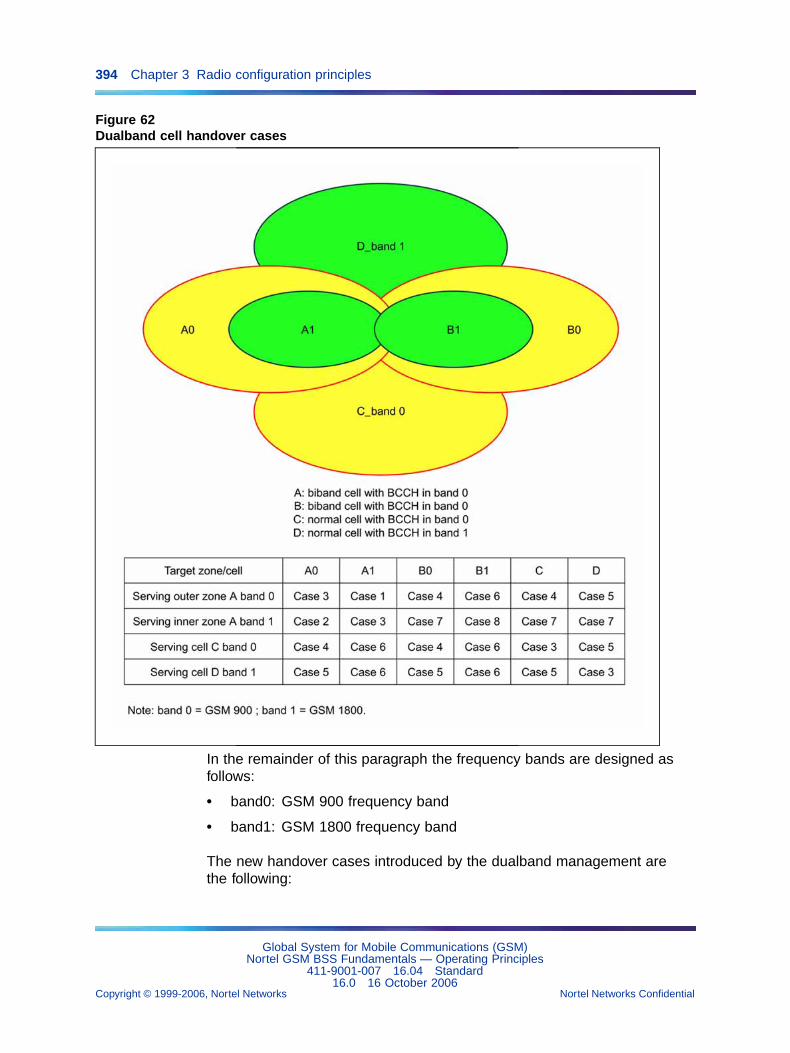
394 Chapter 3 Radio configuration principles
Figure 62Dualband cell handover cases
In the remainder of this paragraph the frequency bands are designed asfollows:
• band0: GSM 900 frequency band
• band1: GSM 1800 frequency band
The new handover cases introduced by the dualband management arethe following:
Global System for Mobile Communications (GSM)Nortel GSM BSS Fundamentals — Operating Principles
411-9001-007 16.04 Standard16.0 16 October 2006
Copyright © 1999-2006, Nortel Networks Nortel Networks Confidential
.
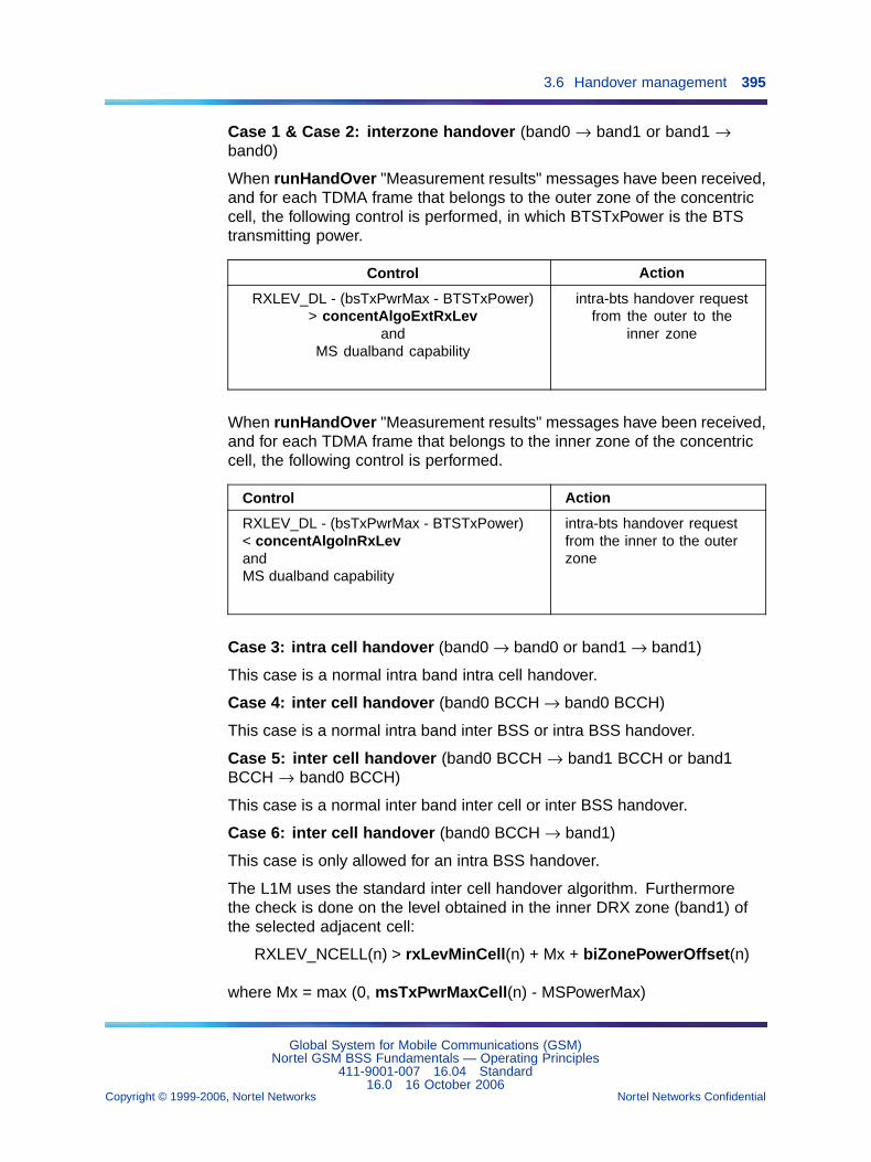
3.6 Handover management 395
Case 1 & Case 2: interzone handover (band0 → band1 or band1 →band0)
When runHandOver "Measurement results" messages have been received,and for each TDMA frame that belongs to the outer zone of the concentriccell, the following control is performed, in which BTSTxPower is the BTStransmitting power.
Control Action
RXLEV_DL - (bsTxPwrMax - BTSTxPower)> concentAlgoExtRxLev
andMS dualband capability
intra-bts handover requestfrom the outer to the
inner zone
When runHandOver "Measurement results" messages have been received,and for each TDMA frame that belongs to the inner zone of the concentriccell, the following control is performed.
Control Action
RXLEV_DL - (bsTxPwrMax - BTSTxPower)< concentAlgolnRxLevandMS dualband capability
intra-bts handover requestfrom the inner to the outerzone
Case 3: intra cell handover (band0 → band0 or band1 → band1)
This case is a normal intra band intra cell handover.
Case 4: inter cell handover (band0 BCCH → band0 BCCH)
This case is a normal intra band inter BSS or intra BSS handover.
Case 5: inter cell handover (band0 BCCH → band1 BCCH or band1BCCH → band0 BCCH)
This case is a normal inter band inter cell or inter BSS handover.
Case 6: inter cell handover (band0 BCCH → band1)
This case is only allowed for an intra BSS handover.
The L1M uses the standard inter cell handover algorithm. Furthermorethe check is done on the level obtained in the inner DRX zone (band1) ofthe selected adjacent cell:
RXLEV_NCELL(n) > rxLevMinCell(n) + Mx + biZonePowerOffset(n)
where Mx = max (0, msTxPwrMaxCell(n) - MSPowerMax)
Global System for Mobile Communications (GSM)Nortel GSM BSS Fundamentals — Operating Principles
411-9001-007 16.04 Standard16.0 16 October 2006
Copyright © 1999-2006, Nortel Networks Nortel Networks Confidential
.
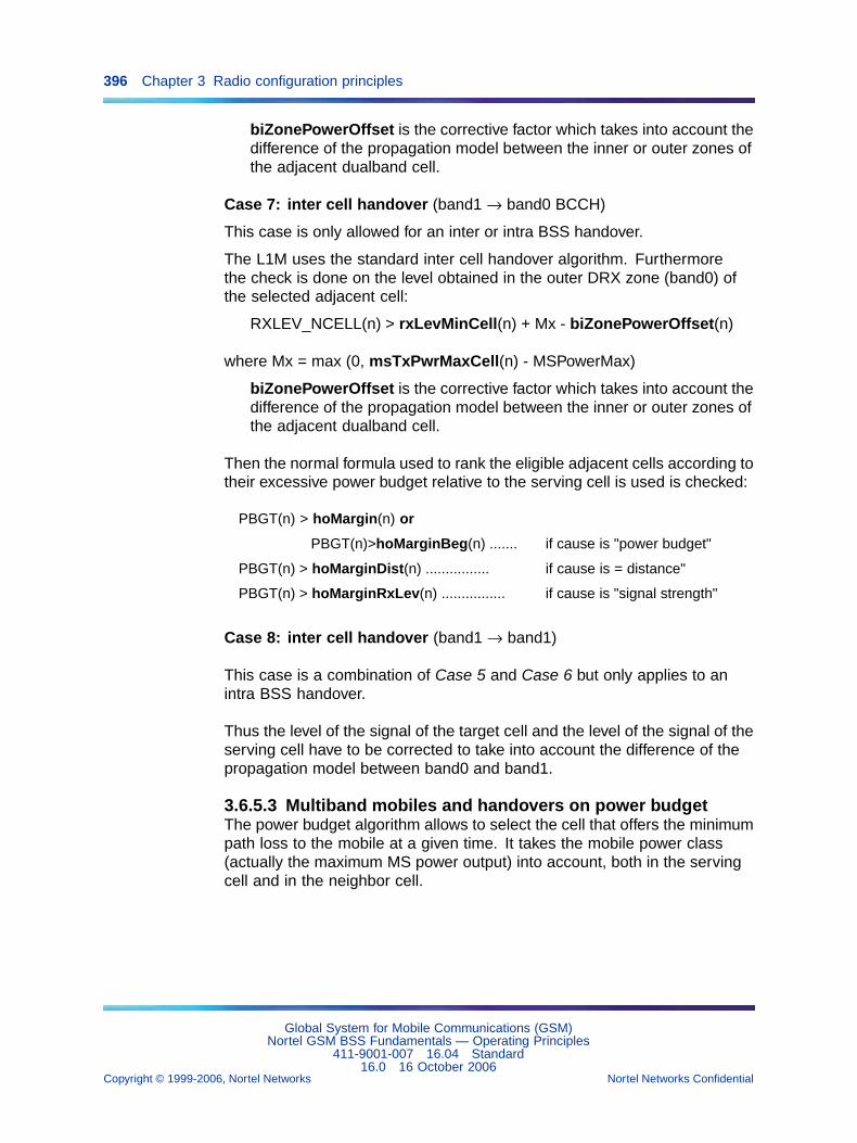
396 Chapter 3 Radio configuration principles
biZonePowerOffset is the corrective factor which takes into account thedifference of the propagation model between the inner or outer zones ofthe adjacent dualband cell.
Case 7: inter cell handover (band1 → band0 BCCH)
This case is only allowed for an inter or intra BSS handover.
The L1M uses the standard inter cell handover algorithm. Furthermorethe check is done on the level obtained in the outer DRX zone (band0) ofthe selected adjacent cell:
RXLEV_NCELL(n) > rxLevMinCell(n) + Mx - biZonePowerOffset(n)
where Mx = max (0, msTxPwrMaxCell(n) - MSPowerMax)
biZonePowerOffset is the corrective factor which takes into account thedifference of the propagation model between the inner or outer zones ofthe adjacent dualband cell.
Then the normal formula used to rank the eligible adjacent cells according totheir excessive power budget relative to the serving cell is used is checked:
PBGT(n) > hoMargin(n) or
PBGT(n)>hoMarginBeg(n) ....... if cause is "power budget"
PBGT(n) > hoMarginDist(n) ................ if cause is = distance"
PBGT(n) > hoMarginRxLev(n) ................ if cause is "signal strength"
Case 8: inter cell handover (band1 → band1)
This case is a combination of Case 5 and Case 6 but only applies to anintra BSS handover.
Thus the level of the signal of the target cell and the level of the signal of theserving cell have to be corrected to take into account the difference of thepropagation model between band0 and band1.
3.6.5.3 Multiband mobiles and handovers on power budgetThe power budget algorithm allows to select the cell that offers the minimumpath loss to the mobile at a given time. It takes the mobile power class(actually the maximum MS power output) into account, both in the servingcell and in the neighbor cell.
Global System for Mobile Communications (GSM)Nortel GSM BSS Fundamentals — Operating Principles
411-9001-007 16.04 Standard16.0 16 October 2006
Copyright © 1999-2006, Nortel Networks Nortel Networks Confidential
.
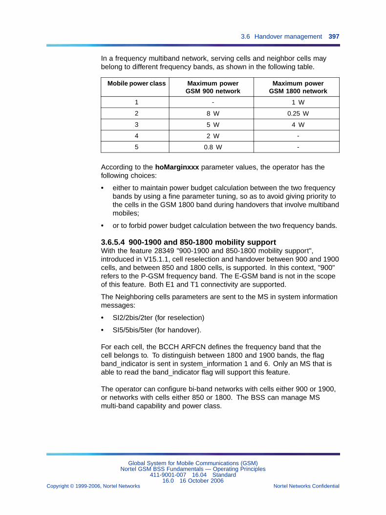
3.6 Handover management 397
In a frequency multiband network, serving cells and neighbor cells maybelong to different frequency bands, as shown in the following table.
Mobile power class Maximum powerGSM 900 network
Maximum powerGSM 1800 network
1 - 1 W
2 8 W 0.25 W
3 5 W 4 W
4 2 W -
5 0.8 W -
According to the hoMarginxxx parameter values, the operator has thefollowing choices:
• either to maintain power budget calculation between the two frequencybands by using a fine parameter tuning, so as to avoid giving priority tothe cells in the GSM 1800 band during handovers that involve multibandmobiles;
• or to forbid power budget calculation between the two frequency bands.
3.6.5.4 900-1900 and 850-1800 mobility supportWith the feature 28349 "900-1900 and 850-1800 mobility support",introduced in V15.1.1, cell reselection and handover between 900 and 1900cells, and between 850 and 1800 cells, is supported. In this context, "900"refers to the P-GSM frequency band. The E-GSM band is not in the scopeof this feature. Both E1 and T1 connectivity are supported.
The Neighboring cells parameters are sent to the MS in system informationmessages:
• SI2/2bis/2ter (for reselection)
• SI5/5bis/5ter (for handover).
For each cell, the BCCH ARFCN defines the frequency band that thecell belongs to. To distinguish between 1800 and 1900 bands, the flagband_indicator is sent in system_information 1 and 6. Only an MS that isable to read the band_indicator flag will support this feature.
The operator can configure bi-band networks with cells either 900 or 1900,or networks with cells either 850 or 1800. The BSS can manage MSmulti-band capability and power class.
Global System for Mobile Communications (GSM)Nortel GSM BSS Fundamentals — Operating Principles
411-9001-007 16.04 Standard16.0 16 October 2006
Copyright © 1999-2006, Nortel Networks Nortel Networks Confidential
.
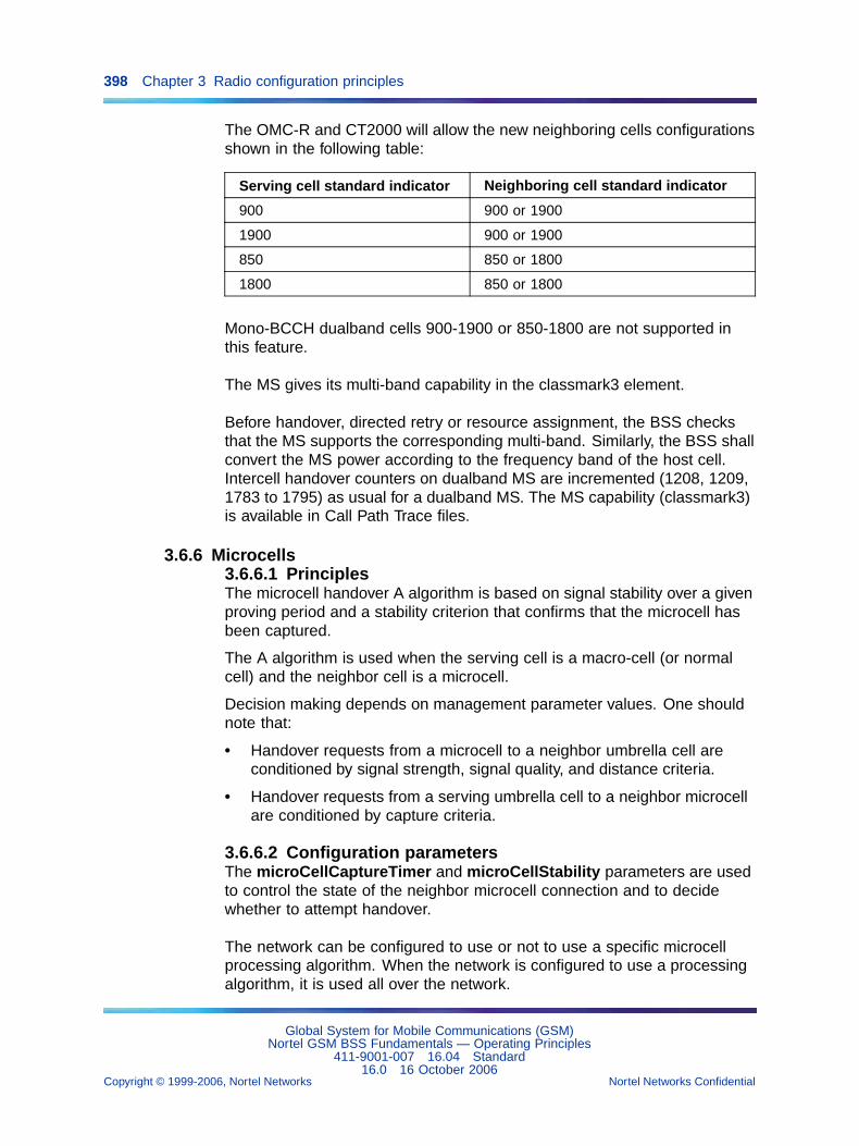
398 Chapter 3 Radio configuration principles
The OMC-R and CT2000 will allow the new neighboring cells configurationsshown in the following table:
Serving cell standard indicator Neighboring cell standard indicator
900 900 or 1900
1900 900 or 1900
850 850 or 1800
1800 850 or 1800
Mono-BCCH dualband cells 900-1900 or 850-1800 are not supported inthis feature.
The MS gives its multi-band capability in the classmark3 element.
Before handover, directed retry or resource assignment, the BSS checksthat the MS supports the corresponding multi-band. Similarly, the BSS shallconvert the MS power according to the frequency band of the host cell.Intercell handover counters on dualband MS are incremented (1208, 1209,1783 to 1795) as usual for a dualband MS. The MS capability (classmark3)is available in Call Path Trace files.
3.6.6 Microcells3.6.6.1 PrinciplesThe microcell handover A algorithm is based on signal stability over a givenproving period and a stability criterion that confirms that the microcell hasbeen captured.
The A algorithm is used when the serving cell is a macro-cell (or normalcell) and the neighbor cell is a microcell.
Decision making depends on management parameter values. One shouldnote that:
• Handover requests from a microcell to a neighbor umbrella cell areconditioned by signal strength, signal quality, and distance criteria.
• Handover requests from a serving umbrella cell to a neighbor microcellare conditioned by capture criteria.
3.6.6.2 Configuration parametersThe microCellCaptureTimer and microCellStability parameters are usedto control the state of the neighbor microcell connection and to decidewhether to attempt handover.
The network can be configured to use or not to use a specific microcellprocessing algorithm. When the network is configured to use a processingalgorithm, it is used all over the network.
Global System for Mobile Communications (GSM)Nortel GSM BSS Fundamentals — Operating Principles
411-9001-007 16.04 Standard16.0 16 October 2006
Copyright © 1999-2006, Nortel Networks Nortel Networks Confidential
.
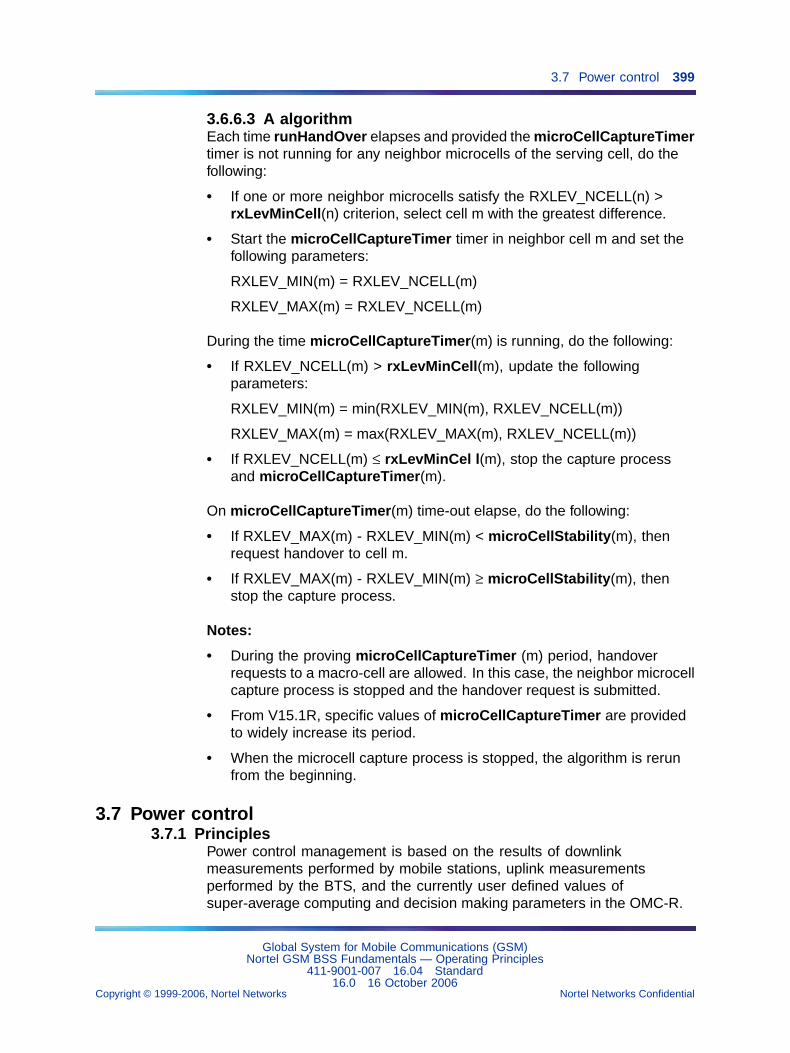
3.7 Power control 399
3.6.6.3 A algorithmEach time runHandOver elapses and provided the microCellCaptureTimertimer is not running for any neighbor microcells of the serving cell, do thefollowing:
• If one or more neighbor microcells satisfy the RXLEV_NCELL(n) >rxLevMinCell(n) criterion, select cell m with the greatest difference.
• Start the microCellCaptureTimer timer in neighbor cell m and set thefollowing parameters:
RXLEV_MIN(m) = RXLEV_NCELL(m)
RXLEV_MAX(m) = RXLEV_NCELL(m)
During the time microCellCaptureTimer(m) is running, do the following:
• If RXLEV_NCELL(m) > rxLevMinCell(m), update the followingparameters:
RXLEV_MIN(m) = min(RXLEV_MIN(m), RXLEV_NCELL(m))
RXLEV_MAX(m) = max(RXLEV_MAX(m), RXLEV_NCELL(m))
• If RXLEV_NCELL(m) ≤ rxLevMinCel l(m), stop the capture processand microCellCaptureTimer(m).
On microCellCaptureTimer(m) time-out elapse, do the following:
• If RXLEV_MAX(m) - RXLEV_MIN(m) < microCellStability(m), thenrequest handover to cell m.
• If RXLEV_MAX(m) - RXLEV_MIN(m) ≥ microCellStability(m), thenstop the capture process.
Notes:
• During the proving microCellCaptureTimer (m) period, handoverrequests to a macro-cell are allowed. In this case, the neighbor microcellcapture process is stopped and the handover request is submitted.
• From V15.1R, specific values of microCellCaptureTimer are providedto widely increase its period.
• When the microcell capture process is stopped, the algorithm is rerunfrom the beginning.
3.7 Power control3.7.1 Principles
Power control management is based on the results of downlinkmeasurements performed by mobile stations, uplink measurementsperformed by the BTS, and the currently user defined values ofsuper-average computing and decision making parameters in the OMC-R.
Global System for Mobile Communications (GSM)Nortel GSM BSS Fundamentals — Operating Principles
411-9001-007 16.04 Standard16.0 16 October 2006
Copyright © 1999-2006, Nortel Networks Nortel Networks Confidential
.
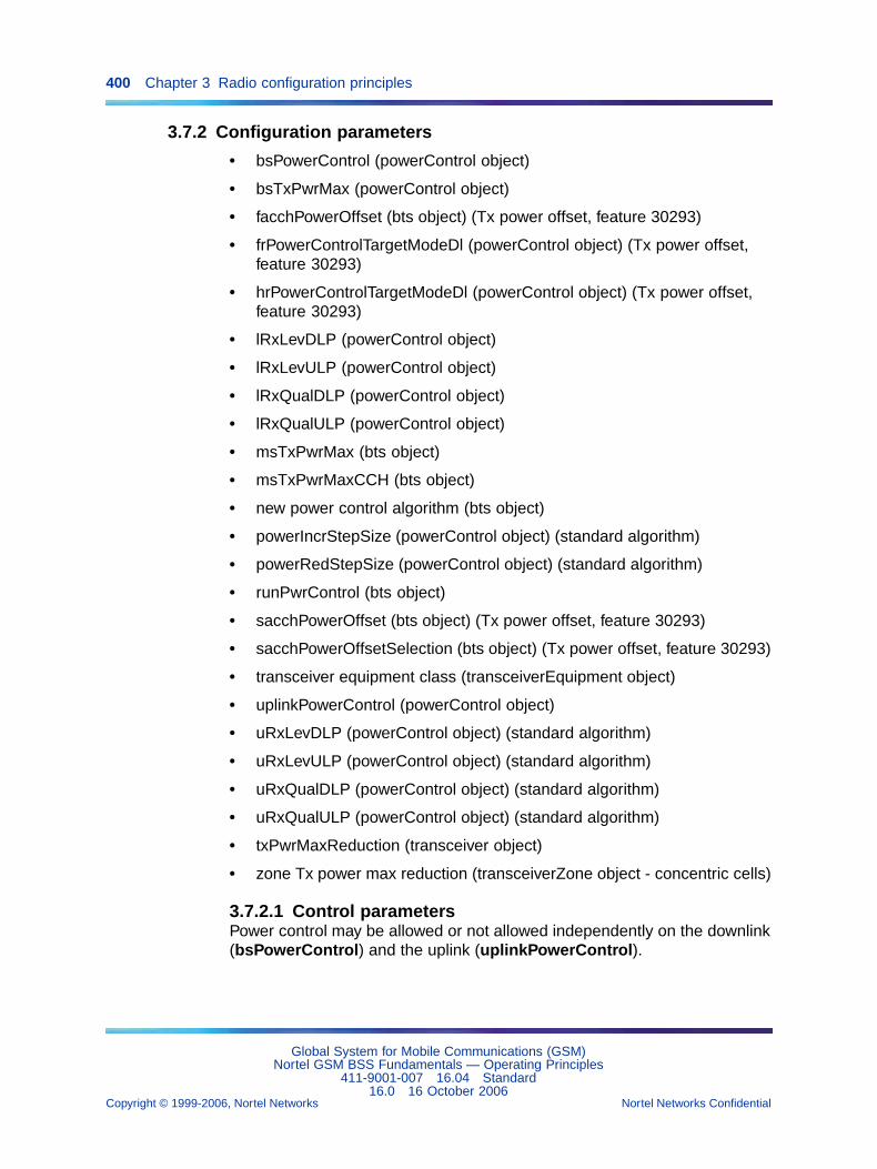
400 Chapter 3 Radio configuration principles
3.7.2 Configuration parameters
• bsPowerControl (powerControl object)
• bsTxPwrMax (powerControl object)
• facchPowerOffset (bts object) (Tx power offset, feature 30293)
• frPowerControlTargetModeDl (powerControl object) (Tx power offset,feature 30293)
• hrPowerControlTargetModeDl (powerControl object) (Tx power offset,feature 30293)
• lRxLevDLP (powerControl object)
• lRxLevULP (powerControl object)
• lRxQualDLP (powerControl object)
• lRxQualULP (powerControl object)
• msTxPwrMax (bts object)
• msTxPwrMaxCCH (bts object)
• new power control algorithm (bts object)
• powerIncrStepSize (powerControl object) (standard algorithm)
• powerRedStepSize (powerControl object) (standard algorithm)
• runPwrControl (bts object)
• sacchPowerOffset (bts object) (Tx power offset, feature 30293)
• sacchPowerOffsetSelection (bts object) (Tx power offset, feature 30293)
• transceiver equipment class (transceiverEquipment object)
• uplinkPowerControl (powerControl object)
• uRxLevDLP (powerControl object) (standard algorithm)
• uRxLevULP (powerControl object) (standard algorithm)
• uRxQualDLP (powerControl object) (standard algorithm)
• uRxQualULP (powerControl object) (standard algorithm)
• txPwrMaxReduction (transceiver object)
• zone Tx power max reduction (transceiverZone object - concentric cells)
3.7.2.1 Control parametersPower control may be allowed or not allowed independently on the downlink(bsPowerControl) and the uplink (uplinkPowerControl).
Global System for Mobile Communications (GSM)Nortel GSM BSS Fundamentals — Operating Principles
411-9001-007 16.04 Standard16.0 16 October 2006
Copyright © 1999-2006, Nortel Networks Nortel Networks Confidential
.
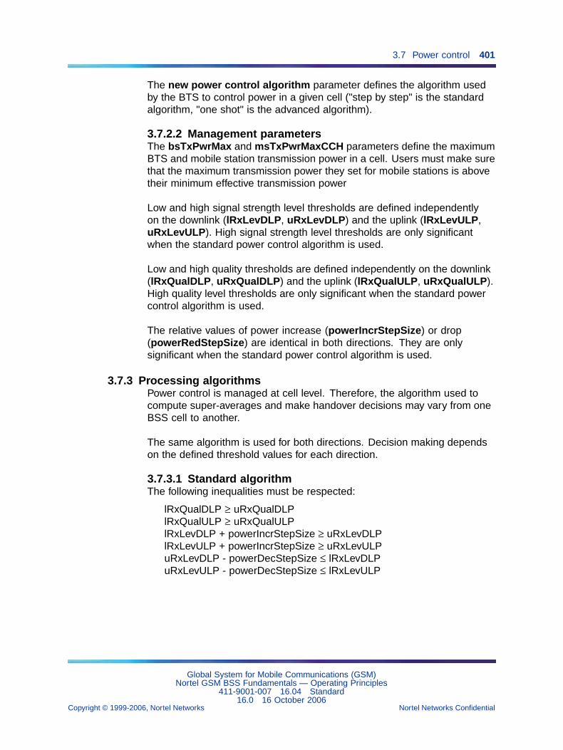
3.7 Power control 401
The new power control algorithm parameter defines the algorithm usedby the BTS to control power in a given cell ("step by step" is the standardalgorithm, "one shot" is the advanced algorithm).
3.7.2.2 Management parametersThe bsTxPwrMax and msTxPwrMaxCCH parameters define the maximumBTS and mobile station transmission power in a cell. Users must make surethat the maximum transmission power they set for mobile stations is abovetheir minimum effective transmission power
Low and high signal strength level thresholds are defined independentlyon the downlink (lRxLevDLP, uRxLevDLP) and the uplink (lRxLevULP,uRxLevULP). High signal strength level thresholds are only significantwhen the standard power control algorithm is used.
Low and high quality thresholds are defined independently on the downlink(lRxQualDLP, uRxQualDLP) and the uplink (lRxQualULP, uRxQualULP).High quality level thresholds are only significant when the standard powercontrol algorithm is used.
The relative values of power increase (powerIncrStepSize) or drop(powerRedStepSize) are identical in both directions. They are onlysignificant when the standard power control algorithm is used.
3.7.3 Processing algorithmsPower control is managed at cell level. Therefore, the algorithm used tocompute super-averages and make handover decisions may vary from oneBSS cell to another.
The same algorithm is used for both directions. Decision making dependson the defined threshold values for each direction.
3.7.3.1 Standard algorithmThe following inequalities must be respected:
lRxQualDLP ≥ uRxQualDLPlRxQualULP ≥ uRxQualULPlRxLevDLP + powerIncrStepSize ≥ uRxLevDLPlRxLevULP + powerIncrStepSize ≥ uRxLevULPuRxLevDLP - powerDecStepSize ≤ lRxLevDLPuRxLevULP - powerDecStepSize ≤ lRxLevULP
Global System for Mobile Communications (GSM)Nortel GSM BSS Fundamentals — Operating Principles
411-9001-007 16.04 Standard16.0 16 October 2006
Copyright © 1999-2006, Nortel Networks Nortel Networks Confidential
.
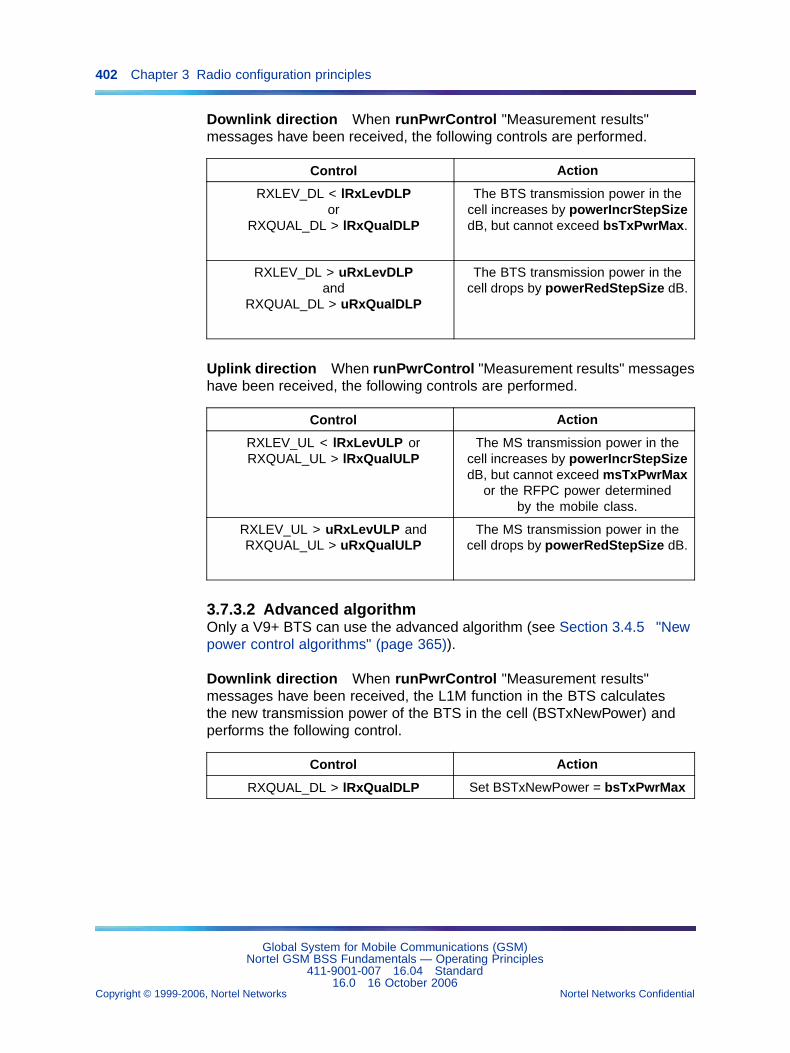
402 Chapter 3 Radio configuration principles
Downlink direction When runPwrControl "Measurement results"messages have been received, the following controls are performed.
Control Action
RXLEV_DL < lRxLevDLPor
RXQUAL_DL > lRxQualDLP
The BTS transmission power in thecell increases by powerIncrStepSizedB, but cannot exceed bsTxPwrMax.
RXLEV_DL > uRxLevDLPand
RXQUAL_DL > uRxQualDLP
The BTS transmission power in thecell drops by powerRedStepSize dB.
Uplink direction When runPwrControl "Measurement results" messageshave been received, the following controls are performed.
Control Action
RXLEV_UL < lRxLevULP orRXQUAL_UL > lRxQualULP
The MS transmission power in thecell increases by powerIncrStepSizedB, but cannot exceed msTxPwrMax
or the RFPC power determinedby the mobile class.
RXLEV_UL > uRxLevULP andRXQUAL_UL > uRxQualULP
The MS transmission power in thecell drops by powerRedStepSize dB.
3.7.3.2 Advanced algorithmOnly a V9+ BTS can use the advanced algorithm (see Section 3.4.5 "Newpower control algorithms" (page 365)).
Downlink direction When runPwrControl "Measurement results"messages have been received, the L1M function in the BTS calculatesthe new transmission power of the BTS in the cell (BSTxNewPower) andperforms the following control.
Control Action
RXQUAL_DL > lRxQualDLP Set BSTxNewPower = bsTxPwrMax
Global System for Mobile Communications (GSM)Nortel GSM BSS Fundamentals — Operating Principles
411-9001-007 16.04 Standard16.0 16 October 2006
Copyright © 1999-2006, Nortel Networks Nortel Networks Confidential
.
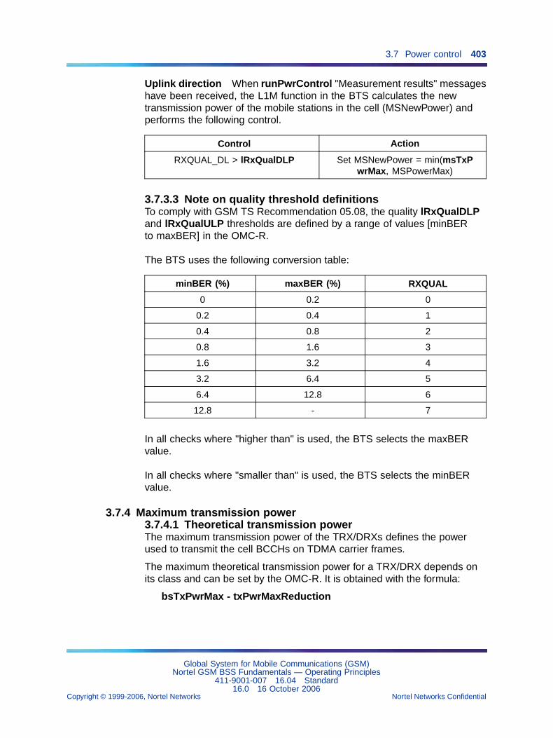
3.7 Power control 403
Uplink direction When runPwrControl "Measurement results" messageshave been received, the L1M function in the BTS calculates the newtransmission power of the mobile stations in the cell (MSNewPower) andperforms the following control.
Control Action
RXQUAL_DL > lRxQualDLP Set MSNewPower = min(msTxPwrMax, MSPowerMax)
3.7.3.3 Note on quality threshold definitionsTo comply with GSM TS Recommendation 05.08, the quality lRxQualDLPand lRxQualULP thresholds are defined by a range of values [minBERto maxBER] in the OMC-R.
The BTS uses the following conversion table:
minBER (%) maxBER (%) RXQUAL
0 0.2 0
0.2 0.4 1
0.4 0.8 2
0.8 1.6 3
1.6 3.2 4
3.2 6.4 5
6.4 12.8 6
12.8 - 7
In all checks where "higher than" is used, the BTS selects the maxBERvalue.
In all checks where "smaller than" is used, the BTS selects the minBERvalue.
3.7.4 Maximum transmission power3.7.4.1 Theoretical transmission powerThe maximum transmission power of the TRX/DRXs defines the powerused to transmit the cell BCCHs on TDMA carrier frames.
The maximum theoretical transmission power for a TRX/DRX depends onits class and can be set by the OMC-R. It is obtained with the formula:
bsTxPwrMax - txPwrMaxReduction
Global System for Mobile Communications (GSM)Nortel GSM BSS Fundamentals — Operating Principles
411-9001-007 16.04 Standard16.0 16 October 2006
Copyright © 1999-2006, Nortel Networks Nortel Networks Confidential
.
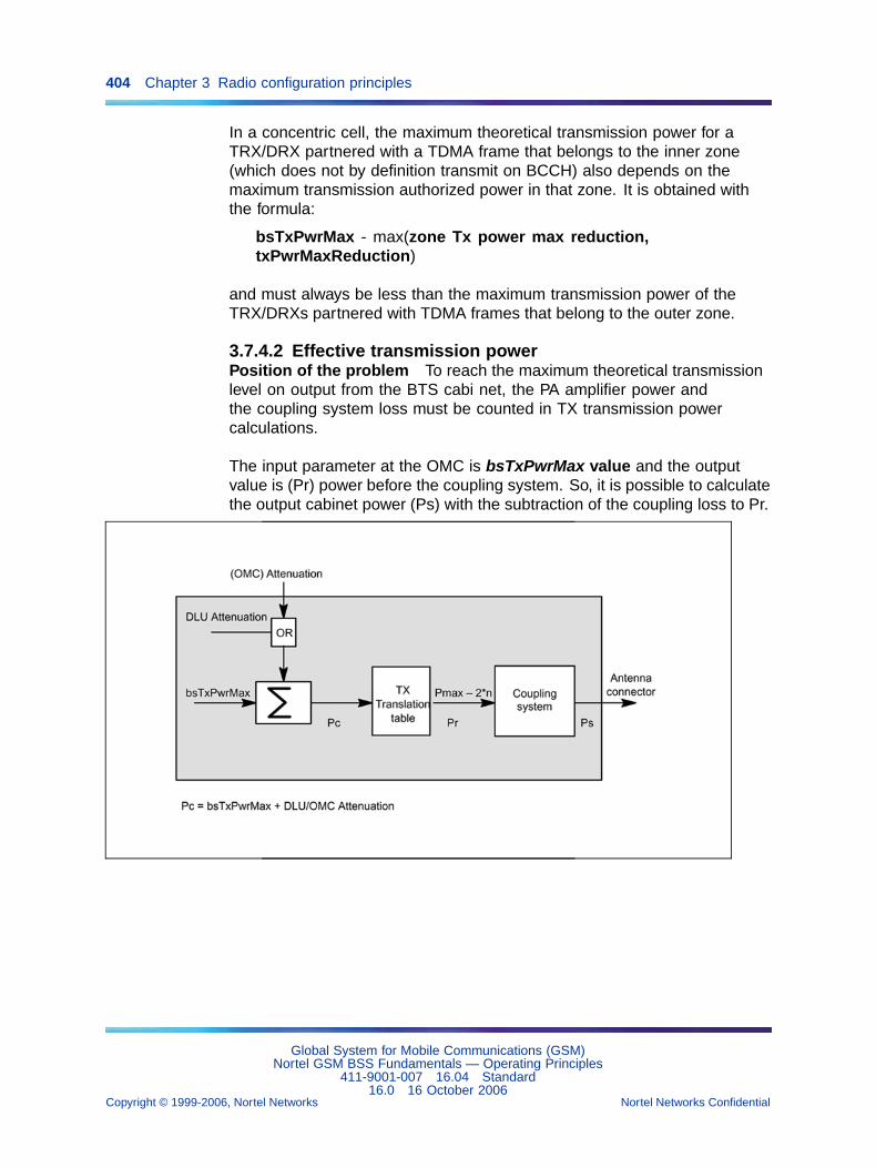
404 Chapter 3 Radio configuration principles
In a concentric cell, the maximum theoretical transmission power for aTRX/DRX partnered with a TDMA frame that belongs to the inner zone(which does not by definition transmit on BCCH) also depends on themaximum transmission authorized power in that zone. It is obtained withthe formula:
bsTxPwrMax - max(zone Tx power max reduction,txPwrMaxReduction)
and must always be less than the maximum transmission power of theTRX/DRXs partnered with TDMA frames that belong to the outer zone.
3.7.4.2 Effective transmission powerPosition of the problem To reach the maximum theoretical transmissionlevel on output from the BTS cabi net, the PA amplifier power andthe coupling system loss must be counted in TX transmission powercalculations.
The input parameter at the OMC is bsTxPwrMax value and the outputvalue is (Pr) power before the coupling system. So, it is possible to calculatethe output cabinet power (Ps) with the subtraction of the coupling loss to Pr.
Global System for Mobile Communications (GSM)Nortel GSM BSS Fundamentals — Operating Principles
411-9001-007 16.04 Standard16.0 16 October 2006
Copyright © 1999-2006, Nortel Networks Nortel Networks Confidential
.
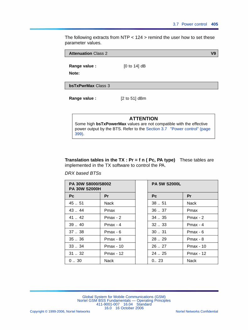
3.7 Power control 405
The following extracts from NTP < 124 > remind the user how to set theseparameter values.
Attenuation Class 2 V9
Range value : [0 to 14] dB
Note:
bsTxPwrMax Class 3
Range value : [2 to 51] dBm
ATTENTIONSome high bsTxPowerMax values are not compatible with the effectivepower output by the BTS. Refer to the Section 3.7 "Power control" (page399).
Translation tables in the TX : Pr = f n ( Pc, PA type) These tables areimplemented in the TX software to control the PA.
DRX based BTSs
PA 30W S8000/S8002PA 30W S2000H
PA 5W S2000L
Pc Pr Pc Pr
45 .. 51 Nack 38 .. 51 Nack
43 .. 44 Pmax 36 .. 37 Pmax
41 .. 42 Pmax - 2 34 .. 35 Pmax - 2
39 .. 40 Pmax - 4 32 .. 33 Pmax - 4
37 .. 38 Pmax - 6 30 .. 31 Pmax - 6
35 .. 36 Pmax - 8 28 .. 29 Pmax - 8
33 .. 34 Pmax - 10 26 .. 27 Pmax - 10
31 .. 32 Pmax - 12 24 .. 25 Pmax - 12
0 .. 30 Nack 0.. 23 Nack
Global System for Mobile Communications (GSM)Nortel GSM BSS Fundamentals — Operating Principles
411-9001-007 16.04 Standard16.0 16 October 2006
Copyright © 1999-2006, Nortel Networks Nortel Networks Confidential
.
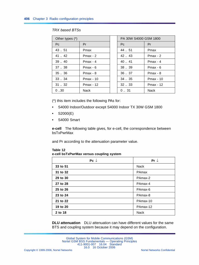
406 Chapter 3 Radio configuration principles
TRX based BTSs
Other types (*) PA 30W S4000 GSM 1800
Pc Pr Pc Pr
43 .. 51 Pmax 44 .. 51 Pmax
41 .. 42 Pmax - 2 42 .. 43 Pmax - 2
39 .. 40 Pmax - 4 40 .. 41 Pmax - 4
37 .. 38 Pmax - 6 38 .. 39 Pmax - 6
35 .. 36 Pmax - 8 36 .. 37 Pmax - 8
33 .. 34 Pmax - 10 34 .. 35 Pmax - 10
31 .. 32 Pmax - 12 32 .. 33 Pmax - 12
0 ..30 Nack 0 .. 31 Nack
(*) this item includes the following PAs for:
• S4000 Indoor/Outdoor except S4000 Indoor TX 30W GSM 1800
• S2000(E)
• S4000 Smart
e-cell The following table gives, for e-cell, the correspondence betweenbsTxPwrMax
and Pr according to the attenuation parameter value.
Table 12e-cell bsTxPwrMax versus coupling system
Pc ↓ Pr ↓
33 to 51 Nack
31 to 32 PAmax
29 to 30 PAmax-2
27 to 28 PAmax-4
25 to 26 PAmax-6
23 to 24 PAmax-8
21 to 22 PAmax-10
19 to 20 PAmax-12
2 to 18 Nack
DLU attenuation DLU attenuation can have different values for the sameBTS and coupling system because it may depend on the configuration.
Global System for Mobile Communications (GSM)Nortel GSM BSS Fundamentals — Operating Principles
411-9001-007 16.04 Standard16.0 16 October 2006
Copyright © 1999-2006, Nortel Networks Nortel Networks Confidential
.
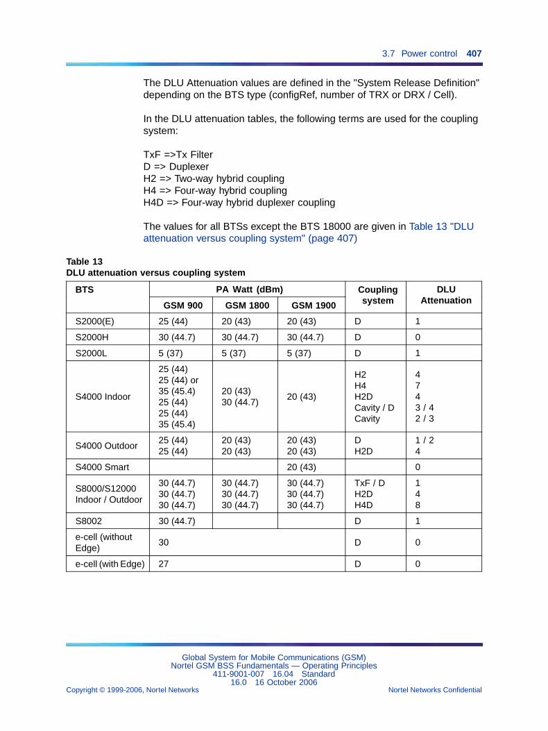
3.7 Power control 407
The DLU Attenuation values are defined in the "System Release Definition"depending on the BTS type (configRef, number of TRX or DRX / Cell).
In the DLU attenuation tables, the following terms are used for the couplingsystem:
TxF =>Tx FilterD => DuplexerH2 => Two-way hybrid couplingH4 => Four-way hybrid couplingH4D => Four-way hybrid duplexer coupling
The values for all BTSs except the BTS 18000 are given in Table 13 "DLUattenuation versus coupling system" (page 407)
Table 13DLU attenuation versus coupling system
PA Watt (dBm)BTS
GSM 900 GSM 1800 GSM 1900
Couplingsystem
DLUAttenuation
S2000(E) 25 (44) 20 (43) 20 (43) D 1
S2000H 30 (44.7) 30 (44.7) 30 (44.7) D 0
S2000L 5 (37) 5 (37) 5 (37) D 1
S4000 Indoor
25 (44)25 (44) or35 (45.4)25 (44)25 (44)35 (45.4)
20 (43)30 (44.7)
20 (43)
H2H4H2DCavity / DCavity
4743 / 42 / 3
S4000 Outdoor25 (44)25 (44)
20 (43)20 (43)
20 (43)20 (43)
DH2D
1 / 24
S4000 Smart 20 (43) 0
S8000/S12000Indoor / Outdoor
30 (44.7)30 (44.7)30 (44.7)
30 (44.7)30 (44.7)30 (44.7)
30 (44.7)30 (44.7)30 (44.7)
TxF / DH2DH4D
148
S8002 30 (44.7) D 1
e-cell (withoutEdge)
30 D 0
e-cell (with Edge) 27 D 0
Global System for Mobile Communications (GSM)Nortel GSM BSS Fundamentals — Operating Principles
411-9001-007 16.04 Standard16.0 16 October 2006
Copyright © 1999-2006, Nortel Networks Nortel Networks Confidential
.
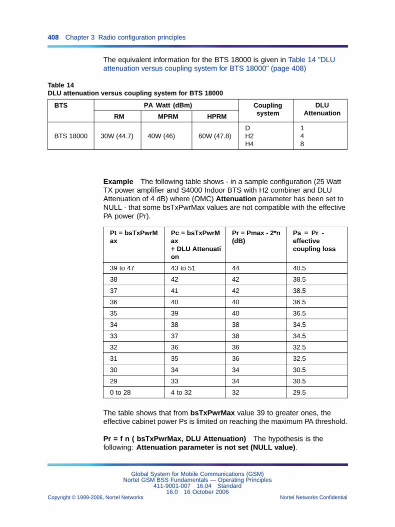
408 Chapter 3 Radio configuration principles
The equivalent information for the BTS 18000 is given in Table 14 "DLUattenuation versus coupling system for BTS 18000" (page 408)
Table 14DLU attenuation versus coupling system for BTS 18000
PA Watt (dBm)BTS
RM MPRM HPRM
Couplingsystem
DLUAttenuation
BTS 18000 30W (44.7) 40W (46) 60W (47.8)DH2H4
148
Example The following table shows - in a sample configuration (25 WattTX power amplifier and S4000 Indoor BTS with H2 combiner and DLUAttenuation of 4 dB) where (OMC) Attenuation parameter has been set toNULL - that some bsTxPwrMax values are not compatible with the effectivePA power (Pr).
Pt = bsTxPwrMax
Pc = bsTxPwrMax+ DLU Attenuation
Pr = Pmax - 2*n(dB)
Ps = Pr -effectivecoupling loss
39 to 47 43 to 51 44 40.5
38 42 42 38.5
37 41 42 38.5
36 40 40 36.5
35 39 40 36.5
34 38 38 34.5
33 37 38 34.5
32 36 36 32.5
31 35 36 32.5
30 34 34 30.5
29 33 34 30.5
0 to 28 4 to 32 32 29.5
The table shows that from bsTxPwrMax value 39 to greater ones, theeffective cabinet power Ps is limited on reaching the maximum PA threshold.
Pr = f n ( bsTxPwrMax, DLU Attenuation) The hypothesis is thefollowing: Attenuation parameter is not set (NULL value).
Global System for Mobile Communications (GSM)Nortel GSM BSS Fundamentals — Operating Principles
411-9001-007 16.04 Standard16.0 16 October 2006
Copyright © 1999-2006, Nortel Networks Nortel Networks Confidential
.
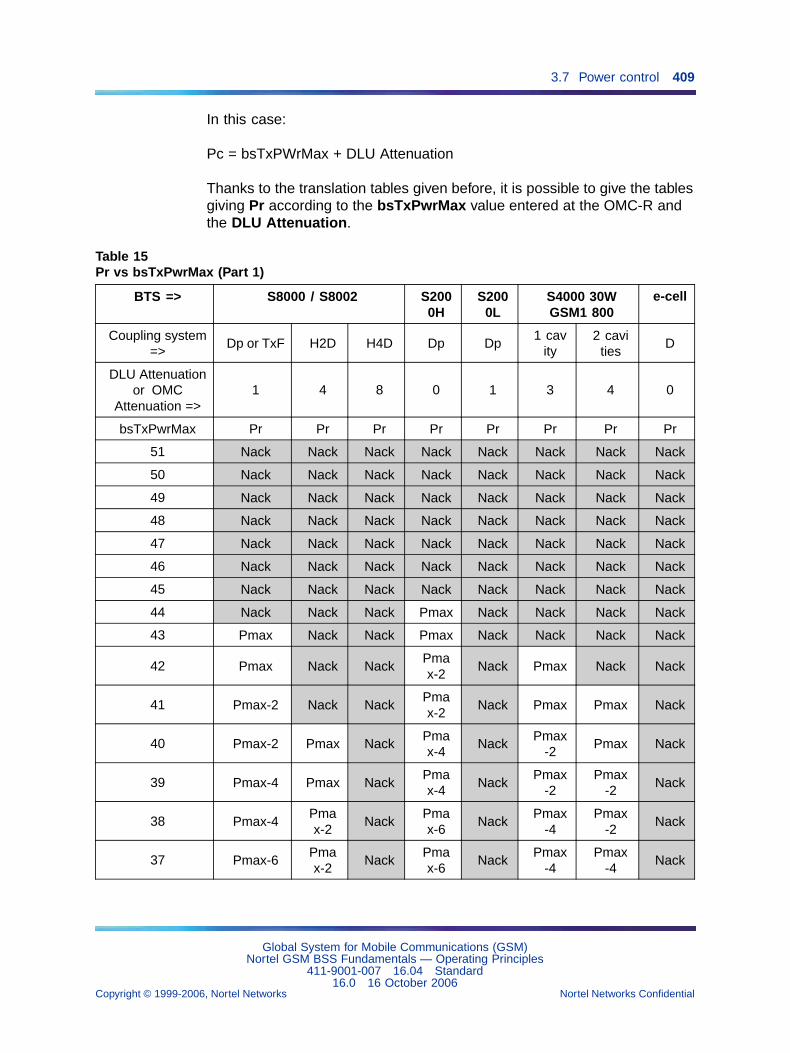
3.7 Power control 409
In this case:
Pc = bsTxPWrMax + DLU Attenuation
Thanks to the translation tables given before, it is possible to give the tablesgiving Pr according to the bsTxPwrMax value entered at the OMC-R andthe DLU Attenuation.
Table 15Pr vs bsTxPwrMax (Part 1)
BTS => S8000 / S8002 S2000H
S2000L
S4000 30WGSM1 800
e-cell
Coupling system=>
Dp or TxF H2D H4D Dp Dp1 cav
ity2 cavi
tiesD
DLU Attenuationor OMC
Attenuation =>1 4 8 0 1 3 4 0
bsTxPwrMax Pr Pr Pr Pr Pr Pr Pr Pr
51 Nack Nack Nack Nack Nack Nack Nack Nack
50 Nack Nack Nack Nack Nack Nack Nack Nack
49 Nack Nack Nack Nack Nack Nack Nack Nack
48 Nack Nack Nack Nack Nack Nack Nack Nack
47 Nack Nack Nack Nack Nack Nack Nack Nack
46 Nack Nack Nack Nack Nack Nack Nack Nack
45 Nack Nack Nack Nack Nack Nack Nack Nack
44 Nack Nack Nack Pmax Nack Nack Nack Nack
43 Pmax Nack Nack Pmax Nack Nack Nack Nack
42 Pmax Nack NackPmax-2
Nack Pmax Nack Nack
41 Pmax-2 Nack NackPmax-2
Nack Pmax Pmax Nack
40 Pmax-2 Pmax NackPmax-4
NackPmax
-2Pmax Nack
39 Pmax-4 Pmax NackPmax-4
NackPmax
-2Pmax
-2Nack
38 Pmax-4Pmax-2
NackPmax-6
NackPmax
-4Pmax
-2Nack
37 Pmax-6Pmax-2
NackPmax-6
NackPmax
-4Pmax
-4Nack
Global System for Mobile Communications (GSM)Nortel GSM BSS Fundamentals — Operating Principles
411-9001-007 16.04 Standard16.0 16 October 2006
Copyright © 1999-2006, Nortel Networks Nortel Networks Confidential
.
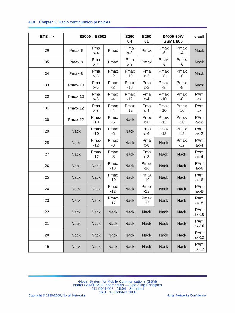
410 Chapter 3 Radio configuration principles
BTS => S8000 / S8002 S2000H
S2000L
S4000 30WGSM1 800
e-cell
36 Pmax-6Pmax-4
PmaxPmax-8
PmaxPmax
-6Pmax
-4Nack
35 Pmax-8Pmax-4
PmaxPmax-8
PmaxPmax
-6Pmax
-6Nack
34 Pmax-8Pmax-6
Pmax-2
Pmax-10
Pmax-2
Pmax-8
Pmax-6
Nack
33 Pmax-10Pmax-6
Pmax-2
Pmax-10
Pmax-2
Pmax-8
Pmax-8
Nack
32 Pmax-10Pmax-8
Pmax-4
Pmax-12
Pmax-4
Pmax-10
Pmax-8
PAmax
31 Pmax-12Pmax-8
Pmax-4
Pmax-12
Pmax-4
Pmax-10
Pmax-10
PAmax
30 Pmax-12Pmax-10
Pmax-6
NackPmax-6
Pmax-12
Pmax-10
PAmax-2
29 NackPmax-10
Pmax-6
NackPmax-6
Pmax-12
Pmax-12
PAmax-2
28 NackPmax-12
Pmax-8
NackPmax-8
NackPmax-12
PAmax-4
27 NackPmax-12
Pmax-8
NackPmax-8
Nack NackPAmax-4
26 Nack NackPmax-10
NackPmax-10
Nack NackPAmax-6
25 Nack NackPmax-10
NackPmax-10
Nack NackPAmax-6
24 Nack NackPmax-12
NackPmax-12
Nack NackPAmax-8
23 Nack NackPmax-12
NackPmax-12
Nack NackPAmax-8
22 Nack Nack Nack Nack Nack Nack NackPAmax-10
21 Nack Nack Nack Nack Nack Nack NackPAmax-10
20 Nack Nack Nack Nack Nack Nack NackPAmax-12
19 Nack Nack Nack Nack Nack Nack NackPAmax-12
Global System for Mobile Communications (GSM)Nortel GSM BSS Fundamentals — Operating Principles
411-9001-007 16.04 Standard16.0 16 October 2006
Copyright © 1999-2006, Nortel Networks Nortel Networks Confidential
.
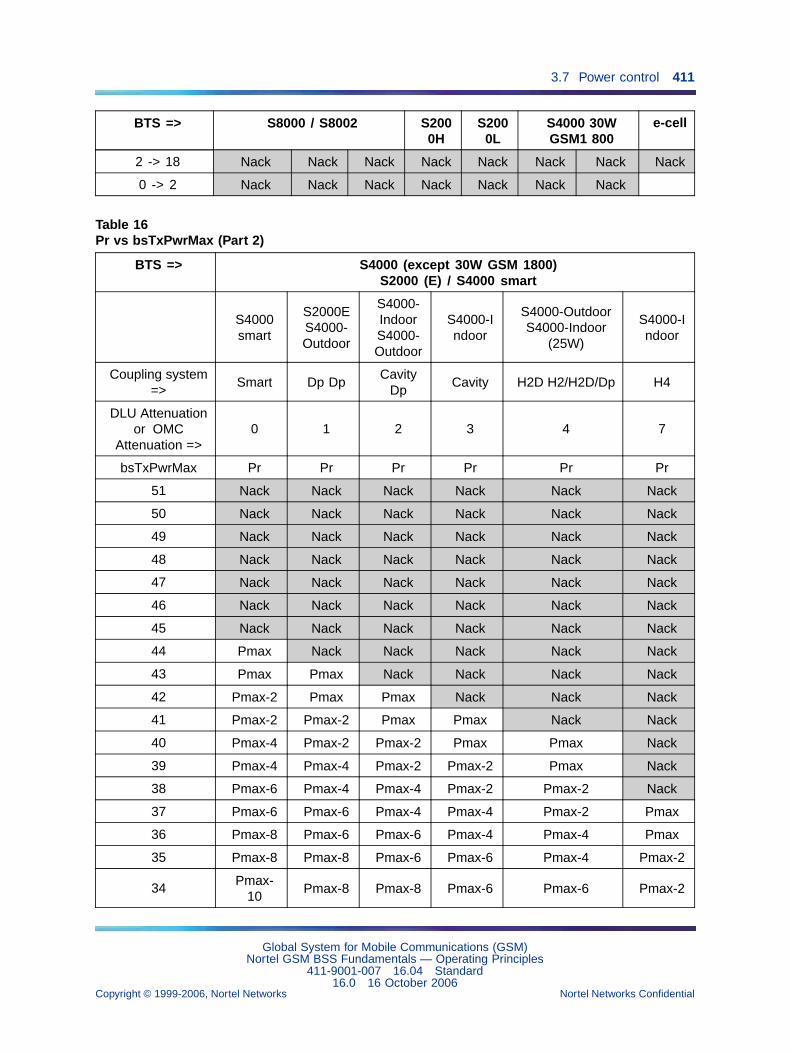
3.7 Power control 411
BTS => S8000 / S8002 S2000H
S2000L
S4000 30WGSM1 800
e-cell
2 -> 18 Nack Nack Nack Nack Nack Nack Nack Nack
0 -> 2 Nack Nack Nack Nack Nack Nack Nack
Table 16Pr vs bsTxPwrMax (Part 2)
BTS => S4000 (except 30W GSM 1800)S2000 (E) / S4000 smart
S4000smart
S2000ES4000-Outdoor
S4000-IndoorS4000-Outdoor
S4000-Indoor
S4000-OutdoorS4000-Indoor
(25W)
S4000-Indoor
Coupling system=>
Smart Dp DpCavity
DpCavity H2D H2/H2D/Dp H4
DLU Attenuationor OMC
Attenuation =>0 1 2 3 4 7
bsTxPwrMax Pr Pr Pr Pr Pr Pr
51 Nack Nack Nack Nack Nack Nack
50 Nack Nack Nack Nack Nack Nack
49 Nack Nack Nack Nack Nack Nack
48 Nack Nack Nack Nack Nack Nack
47 Nack Nack Nack Nack Nack Nack
46 Nack Nack Nack Nack Nack Nack
45 Nack Nack Nack Nack Nack Nack
44 Pmax Nack Nack Nack Nack Nack
43 Pmax Pmax Nack Nack Nack Nack
42 Pmax-2 Pmax Pmax Nack Nack Nack
41 Pmax-2 Pmax-2 Pmax Pmax Nack Nack
40 Pmax-4 Pmax-2 Pmax-2 Pmax Pmax Nack
39 Pmax-4 Pmax-4 Pmax-2 Pmax-2 Pmax Nack
38 Pmax-6 Pmax-4 Pmax-4 Pmax-2 Pmax-2 Nack
37 Pmax-6 Pmax-6 Pmax-4 Pmax-4 Pmax-2 Pmax
36 Pmax-8 Pmax-6 Pmax-6 Pmax-4 Pmax-4 Pmax
35 Pmax-8 Pmax-8 Pmax-6 Pmax-6 Pmax-4 Pmax-2
34Pmax-
10Pmax-8 Pmax-8 Pmax-6 Pmax-6 Pmax-2
Global System for Mobile Communications (GSM)Nortel GSM BSS Fundamentals — Operating Principles
411-9001-007 16.04 Standard16.0 16 October 2006
Copyright © 1999-2006, Nortel Networks Nortel Networks Confidential
.
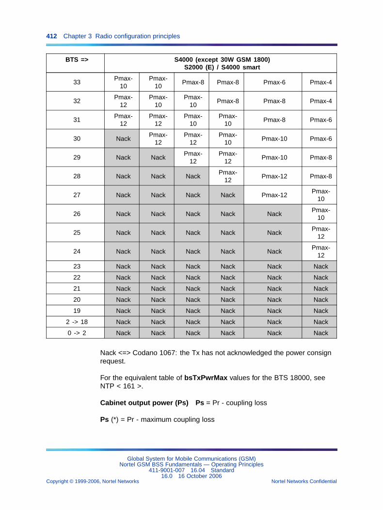
412 Chapter 3 Radio configuration principles
BTS => S4000 (except 30W GSM 1800)S2000 (E) / S4000 smart
33Pmax-
10Pmax-
10Pmax-8 Pmax-8 Pmax-6 Pmax-4
32Pmax-
12Pmax-
10Pmax-
10Pmax-8 Pmax-8 Pmax-4
31Pmax-
12Pmax-
12Pmax-
10Pmax-
10Pmax-8 Pmax-6
30 NackPmax-
12Pmax-
12Pmax-
10Pmax-10 Pmax-6
29 Nack NackPmax-
12Pmax-
12Pmax-10 Pmax-8
28 Nack Nack NackPmax-
12Pmax-12 Pmax-8
27 Nack Nack Nack Nack Pmax-12Pmax-
10
26 Nack Nack Nack Nack NackPmax-
10
25 Nack Nack Nack Nack NackPmax-
12
24 Nack Nack Nack Nack NackPmax-
12
23 Nack Nack Nack Nack Nack Nack
22 Nack Nack Nack Nack Nack Nack
21 Nack Nack Nack Nack Nack Nack
20 Nack Nack Nack Nack Nack Nack
19 Nack Nack Nack Nack Nack Nack
2 -> 18 Nack Nack Nack Nack Nack Nack
0 -> 2 Nack Nack Nack Nack Nack Nack
Nack <=> Codano 1067: the Tx has not acknowledged the power consignrequest.
For the equivalent table of bsTxPwrMax values for the BTS 18000, seeNTP < 161 >.
Cabinet output power (Ps) Ps = Pr - coupling loss
Ps (*) = Pr - maximum coupling loss
Global System for Mobile Communications (GSM)Nortel GSM BSS Fundamentals — Operating Principles
411-9001-007 16.04 Standard16.0 16 October 2006
Copyright © 1999-2006, Nortel Networks Nortel Networks Confidential
.
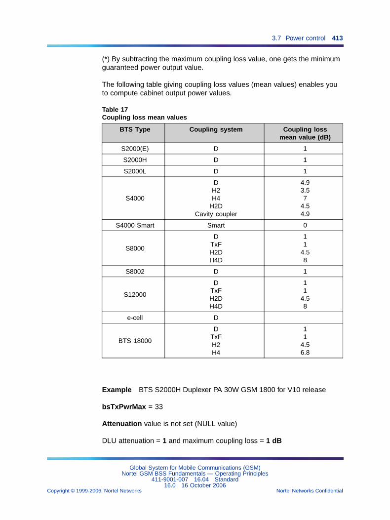
3.7 Power control 413
(*) By subtracting the maximum coupling loss value, one gets the minimumguaranteed power output value.
The following table giving coupling loss values (mean values) enables youto compute cabinet output power values.
Table 17Coupling loss mean values
BTS Type Coupling system Coupling lossmean value (dB)
S2000(E) D 1
S2000H D 1
S2000L D 1
S4000
DH2H4
H2DCavity coupler
4.93.57
4.54.9
S4000 Smart Smart 0
S8000
DTxFH2DH4D
11
4.58
S8002 D 1
S12000
DTxFH2DH4D
11
4.58
e-cell D
BTS 18000
DTxFH2H4
11
4.56.8
Example BTS S2000H Duplexer PA 30W GSM 1800 for V10 release
bsTxPwrMax = 33
Attenuation value is not set (NULL value)
DLU attenuation = 1 and maximum coupling loss = 1 dB
Global System for Mobile Communications (GSM)Nortel GSM BSS Fundamentals — Operating Principles
411-9001-007 16.04 Standard16.0 16 October 2006
Copyright © 1999-2006, Nortel Networks Nortel Networks Confidential
.
414 Chapter 3 Radio configuration principles
Pr = f n (bsTxPwrMax, DLU attenuation) table gives:
Pr = Pmax -10
Ps = Pr - max coupling loss
Ps = (Pmax -10) - 1
Numerical application: Ps = (44.7 -10) -1 = 33.7 dB
ManagementAny change to a cell bsTxPwrMax attribute is sent to the BTS that thenupdates all the TRX/DRXs in that radio cell.
Any change to a TDMA frame txPwrMaxReduction attribute is sent to theBTS that then updates the partnered TRX/DRX.
Any change to the zone Tx power max reduction attribute in a zone ofa concentric cell is sent to the BTS that then updates all the TRX/DRXspartnered with the TDMA frames that belong to that zone.
3.7.4.3 Tx Power Offset for Signalling ChannelsWith the feature 30293 (Tx Power Offset for Signalling Channels),introduced in V16.0, the BTS may use a power offset to transmit signallingbursts. In this case, the related signalling Tx power is above the current Txpower used for voice traffic (but it is still less than or equal to the nominalTx power of the BTS).
The purpose of this feature is to increase the robustness of the signallingchannels (FACCH and SACCH) in the downlink. The signalling channel isbetter protected to avoid call drops in situations where the radio conditionsare deteriorating rapidly. The power offset is triggered only if the loss of thesignalling message is likely to lead to a call drop.
The feature applies to the BTS 18000, the e-cell, and the BTS S8000 andS12000 equipped with e-DRX or DRX-ND3. The feature does not apply toother BTS hardware.
Since this feature improves the downlink robustness for signalling, it ispossible to use a more protected AMR codec in the downlink than theone used in the uplink. Therefore, new parameters have been introducedto define the dedicated power control targets for the uplink and downlinkAMR codec.
The benefit depends on the signalling robustness and it allows the operatorto increase the fractional load and thus the spectrum efficiency. The voicequality is still acceptable thanks to the use of a robust AMR codec.
Global System for Mobile Communications (GSM)Nortel GSM BSS Fundamentals — Operating Principles
411-9001-007 16.04 Standard16.0 16 October 2006
Copyright © 1999-2006, Nortel Networks Nortel Networks Confidential
.
3.8 Call monitoring 415
The following parameters are used to enable/disable and tune the featurein each cell:
• facchPowerOffset (bts object)
• sacchPowerOffset (bts object)
• sacchPowerOffsetSelection (bts object)
• hrPowerControlTargetModeDl (powerControl object)
• frPowerControlTargetModeDl (powerControl object
For a description of these parameters, see NTP < 124 >.
3.8 Call monitoring3.8.1 Principles
Call monitoring is based on the following principles:
• control of the distance that separates the mobile stations from the BTSthat handles their calls
• radio link monitoring
3.8.2 Mobile distance controlMobile distance control is based on the results of uplink measurementsperformed by the BTS and currently user defined super-average computingand decision making parameters in the OMC-R.
3.8.2.1 Configuration parameters
• callClearing (bts object)
• msRangeMax (bts object)
• runCallClear (bts object)
• runHandOver (bts object)
The msRangeMax parameter defines the maximum distance between amobile and the cell that conditions a handover attempt.
The callClearing parameter defines the maximum distance between amobile and the cell that conditions call release.
The following inequality must be respected:
callClearing > msRangeMax
3.8.2.2 Processing algorithmMobile distance control is managed at cell level. Therefore, the algorithmused to compute super-averages and make handover or call releasedecisions may vary from one BSS cell to another.
Global System for Mobile Communications (GSM)Nortel GSM BSS Fundamentals — Operating Principles
411-9001-007 16.04 Standard16.0 16 October 2006
Copyright © 1999-2006, Nortel Networks Nortel Networks Confidential
.
416 Chapter 3 Radio configuration principles
When runCallClear "Measurement results" messages have been received,the L1M function in the BTS performs the following control.
Control Action
MS_BS_DIST > callClearing call clearing request
When runHandOver "Measurement results" messages have been received,the L1M function in the BTS performs the following control.
Control Action
MS_BS_DIST > msRangeMaxinter-bts handover request with
cause "distance"
The first control is performed systematically, regardless of the msRangeMax value, since a handover with cause "distance" may not beexecuted before the mobile goes out of call clearing range.
In case of clear request, the connection state of the radio link changes toCLEAR REQUIRED until the link is released.
The maximum callClearing distance is 35 km for a cell working in normalmode and 90 km for a cell working in extended mode.
3.8.3 Radio link monitoringRadio link monitoring is based on SACCH message analysis. It is performedby the mobile stations on the downlink and the BTS on the uplink.
3.8.3.1 Configuration parameters
• callReestablishment (bts object)
• radioLinkTimeOut (bts object)
• rlf1 (bts object)
• rlf2 (bts object)
• rlf3 (bts object)
• t3109 (bts object)
The radioLinkTimeOut parameter defines the initial value assigned to thecounter (S) in the downlink monitoring process, expressed as multiples ofSACCH frames.
Global System for Mobile Communications (GSM)Nortel GSM BSS Fundamentals — Operating Principles
411-9001-007 16.04 Standard16.0 16 October 2006
Copyright © 1999-2006, Nortel Networks Nortel Networks Confidential
.
3.8 Call monitoring 417
The rlf1 parameter defines the initial value assigned to the counter (CT) inthe uplink monitoring process. The rlf2 and rlf3 parameters define therelative values by which the (CT) counter is stepped up or down for eachSACCH occurrence.
Remark: The OMC-R does not check whether the values assignedto the radioLinkTimeOut and rlf1 parameters by usersfor a same cell are consistent.
3.8.3.2 Processing algorithmsDownlink direction The mobile station executes the monitoring processon SACCH blocks in dedicated mode.
Counter (S) is set to radioLinkTimeOut.
On each SACCH message occurrence, the mobile station does thefollowing:
• If the message is decoded, then S = min(radioL inkTimeOut, S+2)
• If the message is not decoded, then S = max(0, S-1)
If the counter (S) drops to zero, the radio link is declared faulty. An attemptto restore the link is made if call reestablishments are allowed in the cell(callReestablishment).
Uplink direction The FP in the BTS executes the monitoring processon SACCH channels.
The rlf parameter clarification is shown as follows:
The FP runs the following algorithm to monitor the uplink SACCHs(MS-to-BTS direction).
The FrameProcessor sets the CT counter to 0 at channel activation.
On each correct SACCH:
if (CT = 0) then CT=4*rlf1 + 4 else CT=min(4*rlf1 + 4,CT+rlf2)
On each incorrect SACCH:
CT = max(0,CT-rlf3)When CT reaches 0, a CONNECTION FAILURE INDICATION messageis sent to the BSC every T3115, until a Deactivate SACCH or RFCHANNEL RELEASE message is received.
Summary diagram
Global System for Mobile Communications (GSM)Nortel GSM BSS Fundamentals — Operating Principles
411-9001-007 16.04 Standard16.0 16 October 2006
Copyright © 1999-2006, Nortel Networks Nortel Networks Confidential
.
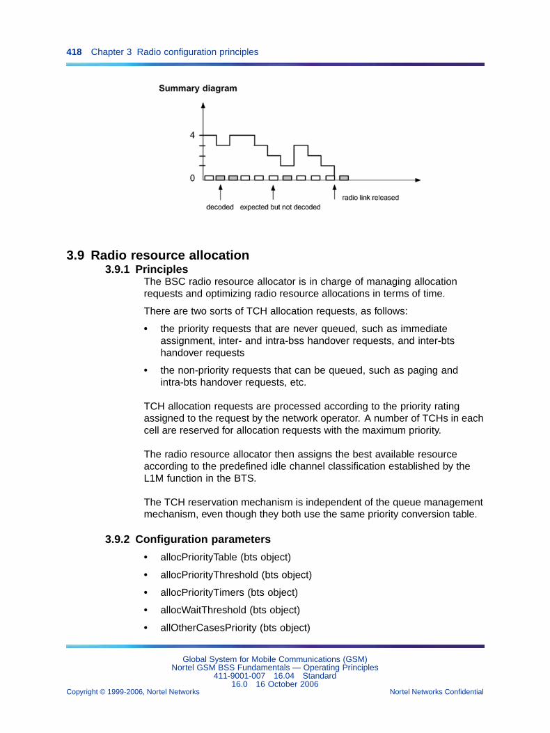
418 Chapter 3 Radio configuration principles
3.9 Radio resource allocation3.9.1 Principles
The BSC radio resource allocator is in charge of managing allocationrequests and optimizing radio resource allocations in terms of time.
There are two sorts of TCH allocation requests, as follows:
• the priority requests that are never queued, such as immediateassignment, inter- and intra-bss handover requests, and inter-btshandover requests
• the non-priority requests that can be queued, such as paging andintra-bts handover requests, etc.
TCH allocation requests are processed according to the priority ratingassigned to the request by the network operator. A number of TCHs in eachcell are reserved for allocation requests with the maximum priority.
The radio resource allocator then assigns the best available resourceaccording to the predefined idle channel classification established by theL1M function in the BTS.
The TCH reservation mechanism is independent of the queue managementmechanism, even though they both use the same priority conversion table.
3.9.2 Configuration parameters
• allocPriorityTable (bts object)
• allocPriorityThreshold (bts object)
• allocPriorityTimers (bts object)
• allocWaitThreshold (bts object)
• allOtherCasesPriority (bts object)
Global System for Mobile Communications (GSM)Nortel GSM BSS Fundamentals — Operating Principles
411-9001-007 16.04 Standard16.0 16 October 2006
Copyright © 1999-2006, Nortel Networks Nortel Networks Confidential
.
3.9 Radio resource allocation 419
• answerPagingPriority (bts object)
• assignRequestPriority (bts object)
• bscQueueingOption (signallingPoint object)
• callReestablishmentPriority (bts object)
• emergencyCallPriority (bts object)
• interCellHOExtPriority (bts object)
• interCellHOIntPriority (bts object)
• intraCellHOIntPriority (bts object)
• intraCellQueueing (bts object)
• otherServicesPriority (bts object)
• small to large zone HO priority (bts object - concentric cells)
The overall permission to queue allocation requests is defined at BSS level(bscQueueingOption).
The permission to queue allocation requests for intra-bts handovers isdefined at cell level (intraCellQueueing) and may differ from one BSS cellto another. It is not significant unless queuing is permitted at BSS level.
The priorities of allocation request processing (xxxPriority) are defined atcell level and may vary from one BSS cell to another.
3.9.3 Priority managementThe external priority of each type of request is converted into an internalpriority (xxxPriority).
The MSC or OMC-R supplies the external priorities, and the user definesthe internal priorities.
The possible priority values are the following:
• External MSC priorities are in the range [1 to 14)].
• External OMC-R priorities are in the range [0 to 17].
• Internal priorities are in the range [0 to 7].
3.9.4 Queuing managementQueuing consists in placing TCH allocation requests in waiting listsaccording to the priority of the request if no TCH resource is available. Allthe requests with the same priority are placed in the same queue.
The internal priority of each type of request is assigned to a given queueusing the allocPriorityTable.
Global System for Mobile Communications (GSM)Nortel GSM BSS Fundamentals — Operating Principles
411-9001-007 16.04 Standard16.0 16 October 2006
Copyright © 1999-2006, Nortel Networks Nortel Networks Confidential
.
420 Chapter 3 Radio configuration principles
Each queue is assigned a maximum request waiting time (allocPriorityTimers) and the maximum number of requests it can contain(allocWaitThreshold).
Remark: If the value of these two parameters is set to zero for a givenpriority, then allocation requests with that priority are neverqueued.
Concerning intracell handover requests, it is recommended not to allowqueuing for this kind of request in monozone cells.In dual-zone cells (concentric cells, dual-coupling cells, and dual-bandcells), queuing must not be allowed at all for intracell handover requests.
3.9.5 Processing algorithmThe following table summarizes the allocation request processing algorithm.
TCH allocation request Processing
Maximum priority andqueuing allowed
If a TCH is available, allocation.If no TCH is available, queuing or requestrefused if the queue is full.
Maximum priority andqueuing not allowed
If a TCH is available, allocation.If no TCH is available, request refused.
Non-maximum priority andqueuing allowed
If the number of available TCHs exceedsallocPriorityThreshold, allocation.If it does not exceed allocPriorityThreshold,queuing or request refused if the queue is full.
Non-maximum priority andqueuing not allowed
If the number of available TCHs exceedsallocPriorityThreshold, allocation.If it does not exceed allocPriorityThreshold,request refused.
3.9.6 Concentric cellsIn a concentric cell, the radio resources are shared between the outer zoneand the inner zone.
Any immediate assignment or incoming inter- or intra-bss handover requestcan:
• either call on radio resources assigned to the outer zone
• or call on radio resources assigned to the inner zone (Direct TCHallocation in the small zone - Feature TF889)
The priority of allocation request processing for intra-bts handovers in aconcentric cell (small to large zone HO priority) is only significant in caseof inter-zone handover from the inner to the outer zone.
Global System for Mobile Communications (GSM)Nortel GSM BSS Fundamentals — Operating Principles
411-9001-007 16.04 Standard16.0 16 October 2006
Copyright © 1999-2006, Nortel Networks Nortel Networks Confidential
.
3.10 Frequency hopping management 421
No processing priority is assigned to allocation requests for intra-zonehandovers. These handovers are initiated by the BTS.
3.9.7 Idle radio channel classificationAvailable radio resources in the BSS are regularly monitored. Themeasurements processed by the BTS are used to classify idle radiochannels according to user-dependent interference levels. The BSC thenprocesses the list of idle channels and arranges them in the order ofallocation priority.
This information is sent to the radio resource allocator. When the allocationrequest is legitimate, it first assigns the idle channels with the lowestinterference level.
In the case of an intracell handover, the target resource is limited to lowinterference level timeslots only. If no low interference level resources areavailable, the requested intracell handover is not executed (Feature TF819 -Intra cell HO Improvement).
Refer to Section 3.4 "Radio measurement processing" (page 355).
3.10 Frequency hopping managementThis paragraph describes frequency hopping management principles andthe processes used by the BSC to redefine frequencies if a frequency islost as a result of a TRX/DRX failure.
3.10.1 Configuration parameters
• bscHopReconfUse (bsc object)
• btsHopReconfRestart (bts object)
• btsIsHopping (bsc object)
• btsThresholdHopReconf (bts object)
• cellAllocation (bts object)
• fhsRef (channel object)
• hoppingSequenceNumber (frequencyHoppingSystem object)
• maio (channel object)
• mobileAllocation (frequencyHoppingSystem object)
• siteGsmFctList (bts SiteManager object)
• zone frequency threshold (transceiverZone object)
Global System for Mobile Communications (GSM)Nortel GSM BSS Fundamentals — Operating Principles
411-9001-007 16.04 Standard16.0 16 October 2006
Copyright © 1999-2006, Nortel Networks Nortel Networks Confidential
.
422 Chapter 3 Radio configuration principles
The mobileAllocation and hoppingSequenceNumber parameters of thefrequencyHoppingSystem objects related to the bts objects define thefrequencies and hopping sequences used by radio time slots (channelobjects) that support frequency hopping.
The maio and fhsRef parameters of the channel objects attached to thetransceiver objects define the frequency hopping laws used by the radiotime slots that support frequency hopping.
The btsIsHopping parameter defines the overall radio channel frequencyhopping conditions in a cell.
The bscHopReconfUse parameter defines the frequency hoppingredefinition conditions in the BSS for BTSs using cavity coupling.The btsHopReconfRestart parameter defines the frequency hoppingredefinition conditions in a BSS cell when a TX is restarted.
The btsThresholdHopReconf parameter defines the minimum number ofworking frequencies required in a cell for the cell to remain operational.
The zone frequency threshold parameter defines the minimum numberof working frequencies in a zone of a concentric cell that allows hoppingfrequency reconfiguration in the zone.
The siteGsmFctList parameter defines the GSM functions supplied by theradio site BCF. When the "freqMgt" function is supplied, it authorizes use ofthe frequency redefinition process.
3.10.2 Frequency hopping management principlesFrequency hopping is not allowed on a radio channel unless it is alsoallowed in the cell covering the TDMA frame.
Frequency hopping on a radio channel carrying a cell BCCH is forbidden.
In one TDMA frame, frequency hopping may be allowed on some radiochannels and disallowed on others.
Each radio channel supporting frequency hopping in a TDMA frame ischaracterized by the following parameters:
• a list of MA hopping frequencies (mobileAllocation)
• an HSN hopping sequence number (hoppingSequenceNumber)
• an index pointing the list of hopping frequencies (maio)
The mobileAllocation list contains a subset of frequencies defined for theparent cell (cellAllocation).
Global System for Mobile Communications (GSM)Nortel GSM BSS Fundamentals — Operating Principles
411-9001-007 16.04 Standard16.0 16 October 2006
Copyright © 1999-2006, Nortel Networks Nortel Networks Confidential
.
3.10 Frequency hopping management 423
A radio channel can use the 1:3 re-use pattern or a unique 1:1 reusepattern, which reduces cochannel interference more effectively. The 1:1reuse pattern has the following restrictions:
• The same Hopping Sequence Number (HSN) and Mobile AllocationIndex Offset (MAIO) are not reused on two different cells in the samesite.
• Different HSNs are not used on cells in the same site.
• The minimum frequency spacing between channels is 400 kHz.
• The MAIOs are distributed equally in order to have the same space (forexample, 600 kHz) between used frequencies.
3.10.3 Frequency redefinition processThe conditions in which the frequency redefinition process is implementedare described in the Section 3.12 "Defense and reconfiguration" (page424).
If the btsThresholdHopReconf parameter defines the nominal number offrequencies in a cell, then the redefinition process is inhibited for that cell.
For a concentric cell, if the zone frequency threshold parameter defines anumber of frequencies greater than the number of available frequencies in azone, then the redefinition process is inhibited for that zone.
Dynamic hopping frequency reconfiguration is only possible in a BTS usingcavity coupling.
The frequency redefinition process calls on all the TDMA frames defined forthe parent cell (or for the partnered zone in a parent concentric cell).
The BSC is charged with the following:
• clear all the TDMA frames that are configured for the cell
• select the TDMA frame to remain unconfigured. If the TDMA framepartnered with the faulty TRX/DRX has priority over other TDMA framesin the cell, it is reconfigured to the prejudice of another one.
• define the new configuration parameters
• reconfigure all TDMA frame radio time slots with the new parametervalues
• report the event to the OMC-R agent
The TDMA frame that is not reconfigured cannot be used until the processis run again.
Global System for Mobile Communications (GSM)Nortel GSM BSS Fundamentals — Operating Principles
411-9001-007 16.04 Standard16.0 16 October 2006
Copyright © 1999-2006, Nortel Networks Nortel Networks Confidential
.
424 Chapter 3 Radio configuration principles
3.10.4 Time slot reconfigurationLet assume that the current cell is configured with the following:
• N TDMA frames
• N frequencies
• M TDMA frames with radio time slots allowed to hop on M frequencies(M is less than or equal to N)
Then, the radio time slots are reconfigured as follows:
• The same hoppingSequenceNumber is assigned to all radio time slotsin the M TDMA frames. It equals the HSN defined for the first time slotallowed to hop in the TDMA frame with the highest priority.
• The same maio index is assigned to all radio time slots allowed to hopin a given TDMA frame and is allotted in the order of the M TDMA framepriority. It is less than M and differs from one TDMA frame to another.
• The same mobileAllocation list of frequencies is assigned to all radiotime slots in the M TDMA frames.
• For all time slots no.0 allowed to hop in the M TDMA frames, if the BCCHfrequency is included in the mobileAllocation list, it is withdrawn fromthe list and the maio index is decreased by 1.
3.11 Frequency plan change for large scale networksAs networks grow, the task of changing a frequency plan needs to besimplified and non-obtrusive into the network traffic.
This function will make maintenance easier and improve quality of servicefor the end-user.
Command file generation for a middle-size network lasts less than 3 hours.Its execution remains within 3 hours, leaving time to fallback if necessary.
3.12 Defense and reconfigurationThis paragraph describes the fail-safe actions taken by the BSC or BTSwhen an equipment problem is detected:
• Defense consists of protecting the BSS against the adverse effects ofcomponent failures by isolating the responsible entity.
• Reconfiguration consists of maintaining the quality of service by enablingredundant equipment.
The BSC (BTS) is required to inform the OMC-R (BSC) of any problems thatmay be encountered and the fail-safe actions performed to resolve them.
Global System for Mobile Communications (GSM)Nortel GSM BSS Fundamentals — Operating Principles
411-9001-007 16.04 Standard16.0 16 October 2006
Copyright © 1999-2006, Nortel Networks Nortel Networks Confidential
.
3.12 Defense and reconfiguration 425
3.12.1 Configuration parameters
• bscHopReconfUse (bsc object)
• btsHopReconfRestart (bts object)
• btsThresholdHopReconf (bts object)
• minNbOfTDMA (bts object)
• redundantPcmPresence (btsSiteManager object)
• traffic PCM allocation priority (transceiver object)
The bscHopReconfUse parameter defines the conditions in which hoppingfrequencies may be reconfigured in the BTSs of a BSS using cavity coupling.The btsHopReconfRestart defines the conditions in which hoppingfrequencies may be reconfigured in a BSS cell when a TX is restarted.
The btsThresholdHopReconf and minNbOfTDMA parameters define theminimum number of working frequencies and TDMA frames required for thecell to remain operational.
The redundantPcmPresence parameter defines the presence of aredundant PCM on a radio site.
The traffic PCM allocation priority parameter defines the priority in whichTDMA time slots on the covered site PCMs are allocated and is used ifAbis PCMs are reconfigured.
3.12.2 Defense3.12.2.1 Radio siteIsolating a radio site triggers the following actions:
• isolate the site radio cells
• lock the LAPD channels used by the site and its GSM equipment (BCFand TRX/DRXs)
• disconnect the PCM time slots used by the site
• report the event to the OMC-R agent that sends alarm notifications andstate change messages for the btsSiteManager object describing thefaulty radio site (operationalState = "disabled" and availabilitySt atus= "dependency") and all dependent objects (see below)
3.12.2.2 Radio cellIsolating a radio cell triggers the following actions:
• isolate the TRX/DRX transceivers in the radio cell
• break the O&M dialogue with the cell GSM equipment (TRX/DRXs)
Global System for Mobile Communications (GSM)Nortel GSM BSS Fundamentals — Operating Principles
411-9001-007 16.04 Standard16.0 16 October 2006
Copyright © 1999-2006, Nortel Networks Nortel Networks Confidential
.
426 Chapter 3 Radio configuration principles
• report the event to the OMC-R agent that sends alarm notifications andstate change messages for the bts object describing the faulty radio cell(operationalState = "disabled" and availabilitySt atus = "dependency")and all dependent objects (see below)
3.12.2.3 Radio transceiverIsolating a radio transceiver triggers the following actions:
• clear the partnered TDMA frame configuration
• report the event to the OMC-R agent that sends alarm notifications andstate change messages for the transceiverEquipment object describingthe faulty TRX/DRX (operationalState = "disabled" and availabilityStatus = "failed") and the partnered transceiver object (see below)
If the number of working frequencies drops below the btsThresholdHo-pReconf operating limit for the related cell, the cell is isolated at the sametime, or else it remains operational.
3.12.2.4 TDMA frameClearing a TDMA frame configuration triggers the following actions:
• inform the BTS of TDMA unavailability and break off all ongoing callson TCHs
• end the dialogue with the partnered TRX/DRX on the RSL link
• report the event to the OMC-R agent that sends alarm notifications andstate change messages for the transceiver object describing the faultyTDMA frame (operationalState = "disabled" and availabilitySt atus ="dependency").
If the TDMA frame is one of the minNbOfTDMA priority frames that mustbe configured for the parent cell, the cell is isolated at the same time, orelse it remains operational.
3.12.2.5 PCM linkIsolating a PCM link triggers the following actions:
• if LAPD channels use the link, force their resource state to "unavailable"
• if traffic channels use the link, break off all calls conveyed on thesechannels
3.12.3 Reconfiguration3.12.3.1 TDMA frameThis procedure is used if the partnered TRX/DRX becomes faulty.
• If a redundant TRX/DRX exists for the radio cell, the following apply:
— The TDMA frame is reconfigured if the TRX/DRX class is compatible.
Global System for Mobile Communications (GSM)Nortel GSM BSS Fundamentals — Operating Principles
411-9001-007 16.04 Standard16.0 16 October 2006
Copyright © 1999-2006, Nortel Networks Nortel Networks Confidential
.
3.12 Defense and reconfiguration 427
— The dialogue with the TRX/DRX on the RSL link is restored.
— The TCHs in the TDMA frame are allotted to radio time slots on oneof the PCM links used by the radio site.
• If no redundant TRX/DRX exists for the radio cell, the following apply:
— If the TDMA frame has priority over another TDMA frame allotted tothe same cell, it is reconfigured on the TRX/DRX partnered with thelow priority TDMA frame if the TRX/DRX class is compatible and theconfiguration of the low priority TDMA frame is cleared.
— If the TDMA frame has not priority over others and respectsfrequency hopping laws, and if the BTS uses cavity coupling, thefrequency redefinition process is executed (see Section 3.10"Frequency hopping management" (page 421)).
— If the TDMA frame has not priority over others and respectsfrequency hopping laws, and if the BTS does not use cavity coupling,the TDMA frame remains operational and does not need to bereconfigured.
3.12.3.2 Radio transceiverTo reconfigure a TRX/DRX, the Level 3 dialogue has to be reestablished.
The frequency redefinition process is executed on the partnered TDMAframe if it is allowed.
3.12.3.3 Radio siteIf the site has to be reconfigured because of a PCM link failure, the followingapply:
• If the LAPD link with the radio site BCF is affected, the BSC reestablishesthe Level 2 dialogue on another PCM link (whether normal or redundant).This supposes that the same time slot is available on the new PCM link.
• If other LAPD links are affected and the GSM function "abisSig" issupplied by the radio site, the BSC sets the redundant PCM link inservice and assigns the same PCM time slot as before to each LAPDlink.
• If traffic channels are affected and the GSM function "abisTraf" issupplied by the radio site, the BSC sets the redundant PCM link inservice and assigns the same PCM time slot as before to each trafficchannel.
Reconfiguration priority is given to the traffic channels conveyed by thehighest priority TDMA frames.
Global System for Mobile Communications (GSM)Nortel GSM BSS Fundamentals — Operating Principles
411-9001-007 16.04 Standard16.0 16 October 2006
Copyright © 1999-2006, Nortel Networks Nortel Networks Confidential
.
428 Chapter 3 Radio configuration principles
3.13 Uplink mapping3.13.1 Principles
Uplink mapping aims at producing uplink coverage maps and consequentlyinterferences matrices based on field measurements (Feature TF876 UplinkMapping).
BTSs measure the signal generated by a mobile tool on a given frequency,and thus obtain field measurements.
A mobile tool is composed of:
• a transmitter
• a test mobile station
• a Dead Reckoning - Global Positioning System (DR-GPS)
Measurements are sent by BTSs to the BSC and then collected by anexternal data server. This server merges the measurements with the datarecorded by the mobile tool, so as to obtain coverage maps.
3.13.2 Prerequisites
• Uplink mapping is applicable to GSM1800 network using softwaresystem release V12.4 (Uplink mapping is therefore not applicable todual-band networks such as GSM900/GSM1800).
• BTSs must be equipped with DCU4 boards only (no DCU2 bands at all).
3.13.3 Configuration parameters
• uplinkMappingChannelNumber (bts object)
• uplinkMappingFreq (bts object)
• uplinkMappingMeasurementMode (bts object)
• uplinkMappingProcessingMode (bts object)
3.13.3.1 Management parametersThe uplinkMappingChannelNumber parameter defines the monitoredtimeslot used during an uplink mapping campaign.
This information is provided to the BTSs by the user through the OMC-R,together with the frequency f0 which is defined by the uplinkMappingFreqparameter. The frequency f0 is used by the transmitter to send a continuoussinusoidal signal to all the cells of the network.
The uplinkMappingMeasurementMode parameter enables to set a BTS inmeasurement mode or in non measurement mode.
Global System for Mobile Communications (GSM)Nortel GSM BSS Fundamentals — Operating Principles
411-9001-007 16.04 Standard16.0 16 October 2006
Copyright © 1999-2006, Nortel Networks Nortel Networks Confidential
.
3.13 Uplink mapping 429
The uplinkMappingProcessingMode parameter enables to set a BSC inmonitoring mode or in idle mode.
3.13.4 Measurement processing3.13.4.1 Hardware installation
• Install the Ethernet kit on the BSC to connect the external data serverto the BSC(s).
• Install an RARP (Reverse Address Resolution Protocol) server in theLAN (Local Area Network) to manage the mapping between BSCEthernet addresses and IP addresses.
3.13.4.2 Configuration
• At the OMC-R, send the values of the frequency f0 and the monitoredTS to each cell of the network:
— Set the bts objects to "locked".
— Set the uplinkMappingChannelNumber and the uplinkMap-pingFreq parameters to their correct values.
— Set the uplinkMappingMeasurementMode parameter to "enabled".
— Set the bts objects to "unlocked".
• Then the network is in idle state: the measurements sent by the BTSs (ifany) are still ignored by the BSC.
3.13.4.3 Activation
• At the OMC-R, set the f0 channel to "locked" through the "set channelstate" action.
• At the OMC-R, set the BSC in monitoring state: set theuplinkMappingProcessingMode parameter to "enabled".
• Then the BSC starts to send measurements to the external data server.
3.13.4.4 Measurement period
• The mobile tool moves through the network.
• the transmitter broadcasts a predefined frequency f0 which is acontinuous sinusoidal signal.
• the test mobile station listens to the BTSs. It is coupled to a DR-GPSto record the position of the transmitter and also information on theserving cell.
• The uplink f0 received level is monitored by all the cells of the network,and level measurements are sent by the BTSs to the BSC and then bythe BSC to an external data server.
Global System for Mobile Communications (GSM)Nortel GSM BSS Fundamentals — Operating Principles
411-9001-007 16.04 Standard16.0 16 October 2006
Copyright © 1999-2006, Nortel Networks Nortel Networks Confidential
.
430 Chapter 3 Radio configuration principles
• The data server collects all the data transmitted by the BSC and mergesthese data with the data recorded by the mobile tool, so as to obtaincoverage maps.
3.13.4.5 Deactivation
• At the OMC-R, set the BSC in idle state: uplinkMappingProcessing-Mode parameter to "disabled".
• Then the BSC stop sending measurements to the external data server.
• At the OMC-R, set the f0 channel to "unlocked" through the "set channelstate" action.
3.13.4.6 Unconfiguration
•— Set the bts objects to "locked".
— Set the uplinkMappingMeasurementMode parameter to "disabled".
— Set the bts objects to "unlocked".
• Then the network is in idle state: BTSs stop collecting and sendingmeasurements. Their nominal configuration is reestablished.
3.14 Hardware constraints (from V14 release):The handover adaptation is not available on DCU2, thus its activation onthis equipment type has the following consequences:
• S4000/S2000E DCU2: this feature is not activated and all PBGT(n) andpower control mechanisms related to the L1mV1 are applied
• S4000/S2000E DCU2/DCU4, this feature created some inconsistenciesbetween TRXs. It is strongly recommended to deactivate the feature,with this kind of BTS.
Global System for Mobile Communications (GSM)Nortel GSM BSS Fundamentals — Operating Principles
411-9001-007 16.04 Standard16.0 16 October 2006
Copyright © 1999-2006, Nortel Networks Nortel Networks Confidential
.
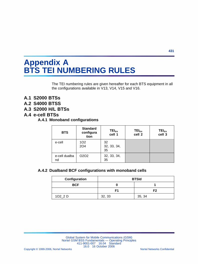
431
Appendix ABTS TEI NUMBERING RULES
The TEI numbering rules are given hereafter for each BTS equipment in allthe configurations available in V13, V14, V15 and V16.
A.1 S2000 BTSsA.2 S4000 BTSSA.3 S2000 H/L BTSsA.4 e-cell BTSs
A.4.1 Monoband configurations
BTSStandardconfigura
tion
TEItrxcell 1
TEItrxcell 2
TEItrxcell 3
e-cell 1O22O4
3232, 33, 34,35
e-cell dualband
O2O2 32, 33, 34,35
A.4.2 Dualband BCF configurations with monoband cells
Configuration BTSId
BCF 0 1
F1 F2
1O2_2 D 32, 33 35, 34
Global System for Mobile Communications (GSM)Nortel GSM BSS Fundamentals — Operating Principles
411-9001-007 16.04 Standard16.0 16 October 2006
Copyright © 1999-2006, Nortel Networks Nortel Networks Confidential
.
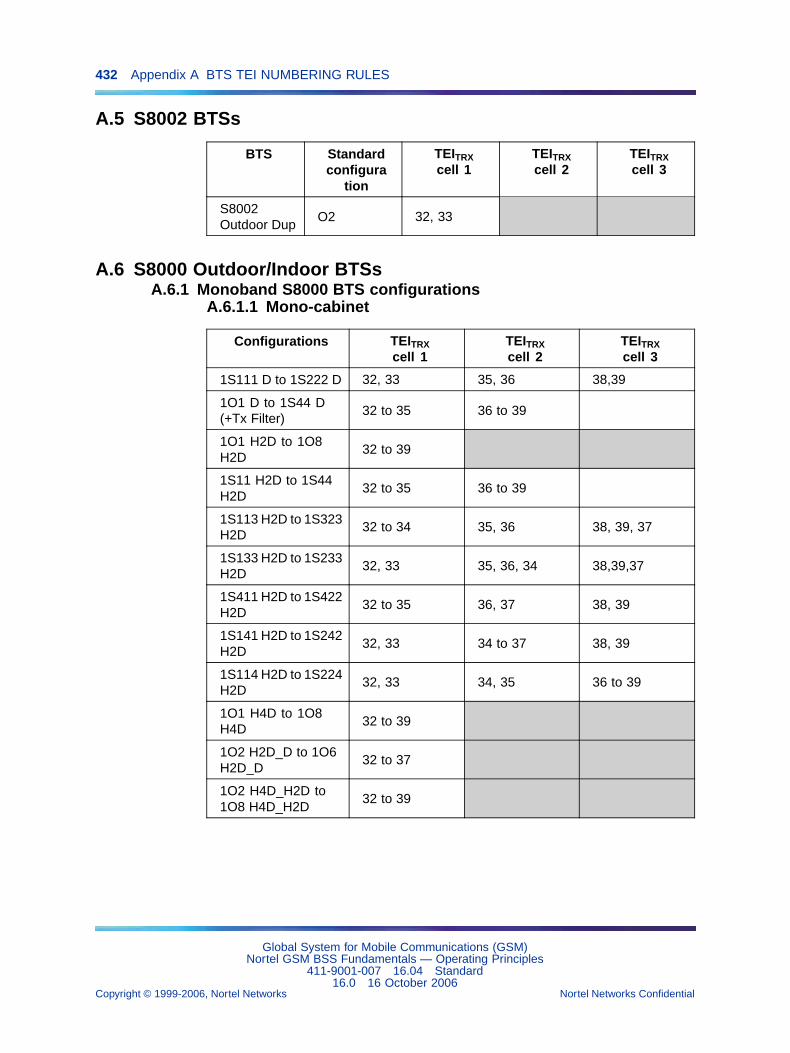
432 Appendix A BTS TEI NUMBERING RULES
A.5 S8002 BTSs
BTS Standardconfigura
tion
TEITRXcell 1
TEITRXcell 2
TEITRXcell 3
S8002Outdoor Dup
O2 32, 33
A.6 S8000 Outdoor/Indoor BTSsA.6.1 Monoband S8000 BTS configurations
A.6.1.1 Mono-cabinet
Configurations TEITRXcell 1
TEITRXcell 2
TEITRXcell 3
1S111 D to 1S222 D 32, 33 35, 36 38,39
1O1 D to 1S44 D(+Tx Filter)
32 to 35 36 to 39
1O1 H2D to 1O8H2D
32 to 39
1S11 H2D to 1S44H2D
32 to 35 36 to 39
1S113 H2D to 1S323H2D
32 to 34 35, 36 38, 39, 37
1S133 H2D to 1S233H2D
32, 33 35, 36, 34 38,39,37
1S411 H2D to 1S422H2D
32 to 35 36, 37 38, 39
1S141 H2D to 1S242H2D
32, 33 34 to 37 38, 39
1S114 H2D to 1S224H2D
32, 33 34, 35 36 to 39
1O1 H4D to 1O8H4D
32 to 39
1O2 H2D_D to 1O6H2D_D
32 to 37
1O2 H4D_H2D to1O8 H4D_H2D
32 to 39
Global System for Mobile Communications (GSM)Nortel GSM BSS Fundamentals — Operating Principles
411-9001-007 16.04 Standard16.0 16 October 2006
Copyright © 1999-2006, Nortel Networks Nortel Networks Confidential
.
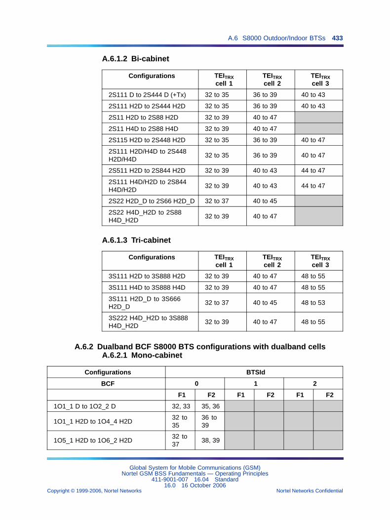
A.6 S8000 Outdoor/Indoor BTSs 433
A.6.1.2 Bi-cabinet
Configurations TEITRXcell 1
TEITRXcell 2
TEITRXcell 3
2S111 D to 2S444 D (+Tx) 32 to 35 36 to 39 40 to 43
2S111 H2D to 2S444 H2D 32 to 35 36 to 39 40 to 43
2S11 H2D to 2S88 H2D 32 to 39 40 to 47
2S11 H4D to 2S88 H4D 32 to 39 40 to 47
2S115 H2D to 2S448 H2D 32 to 35 36 to 39 40 to 47
2S111 H2D/H4D to 2S448H2D/H4D
32 to 35 36 to 39 40 to 47
2S511 H2D to 2S844 H2D 32 to 39 40 to 43 44 to 47
2S111 H4D/H2D to 2S844H4D/H2D
32 to 39 40 to 43 44 to 47
2S22 H2D_D to 2S66 H2D_D 32 to 37 40 to 45
2S22 H4D_H2D to 2S88H4D_H2D
32 to 39 40 to 47
A.6.1.3 Tri-cabinet
Configurations TEITRXcell 1
TEITRXcell 2
TEITRXcell 3
3S111 H2D to 3S888 H2D 32 to 39 40 to 47 48 to 55
3S111 H4D to 3S888 H4D 32 to 39 40 to 47 48 to 55
3S111 H2D_D to 3S666H2D_D
32 to 37 40 to 45 48 to 53
3S222 H4D_H2D to 3S888H4D_H2D
32 to 39 40 to 47 48 to 55
A.6.2 Dualband BCF S8000 BTS configurations with dualband cellsA.6.2.1 Mono-cabinet
Configurations BTSId
BCF 0 1 2
F1 F2 F1 F2 F1 F2
1O1_1 D to 1O2_2 D 32, 33 35, 36
1O1_1 H2D to 1O4_4 H2D32 to35
36 to39
1O5_1 H2D to 1O6_2 H2D32 to37
38, 39
Global System for Mobile Communications (GSM)Nortel GSM BSS Fundamentals — Operating Principles
411-9001-007 16.04 Standard16.0 16 October 2006
Copyright © 1999-2006, Nortel Networks Nortel Networks Confidential
.
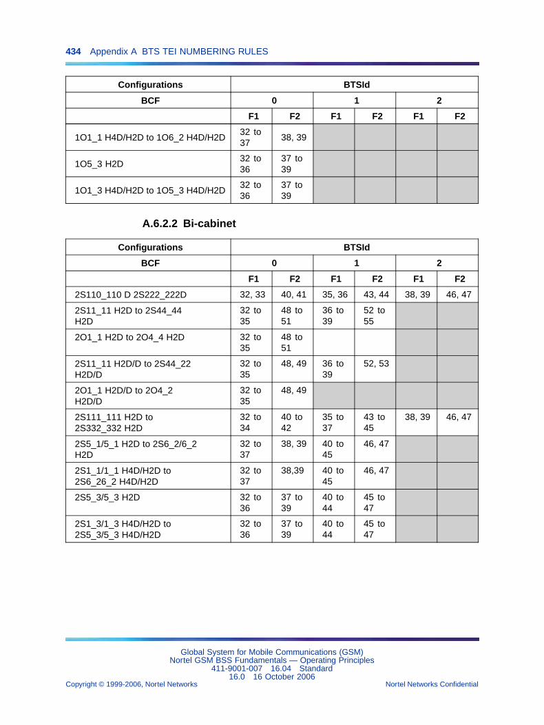
434 Appendix A BTS TEI NUMBERING RULES
Configurations BTSId
BCF 0 1 2
F1 F2 F1 F2 F1 F2
1O1_1 H4D/H2D to 1O6_2 H4D/H2D32 to37
38, 39
1O5_3 H2D32 to36
37 to39
1O1_3 H4D/H2D to 1O5_3 H4D/H2D32 to36
37 to39
A.6.2.2 Bi-cabinet
Configurations BTSId
BCF 0 1 2
F1 F2 F1 F2 F1 F2
2S110_110 D 2S222_222D 32, 33 40, 41 35, 36 43, 44 38, 39 46, 47
2S11_11 H2D to 2S44_44H2D
32 to35
48 to51
36 to39
52 to55
2O1_1 H2D to 2O4_4 H2D 32 to35
48 to51
2S11_11 H2D/D to 2S44_22H2D/D
32 to35
48, 49 36 to39
52, 53
2O1_1 H2D/D to 2O4_2H2D/D
32 to35
48, 49
2S111_111 H2D to2S332_332 H2D
32 to34
40 to42
35 to37
43 to45
38, 39 46, 47
2S5_1/5_1 H2D to 2S6_2/6_2H2D
32 to37
38, 39 40 to45
46, 47
2S1_1/1_1 H4D/H2D to2S6_26_2 H4D/H2D
32 to37
38,39 40 to45
46, 47
2S5_3/5_3 H2D 32 to36
37 to39
40 to44
45 to47
2S1_3/1_3 H4D/H2D to2S5_3/5_3 H4D/H2D
32 to36
37 to39
40 to44
45 to47
Global System for Mobile Communications (GSM)Nortel GSM BSS Fundamentals — Operating Principles
411-9001-007 16.04 Standard16.0 16 October 2006
Copyright © 1999-2006, Nortel Networks Nortel Networks Confidential
.
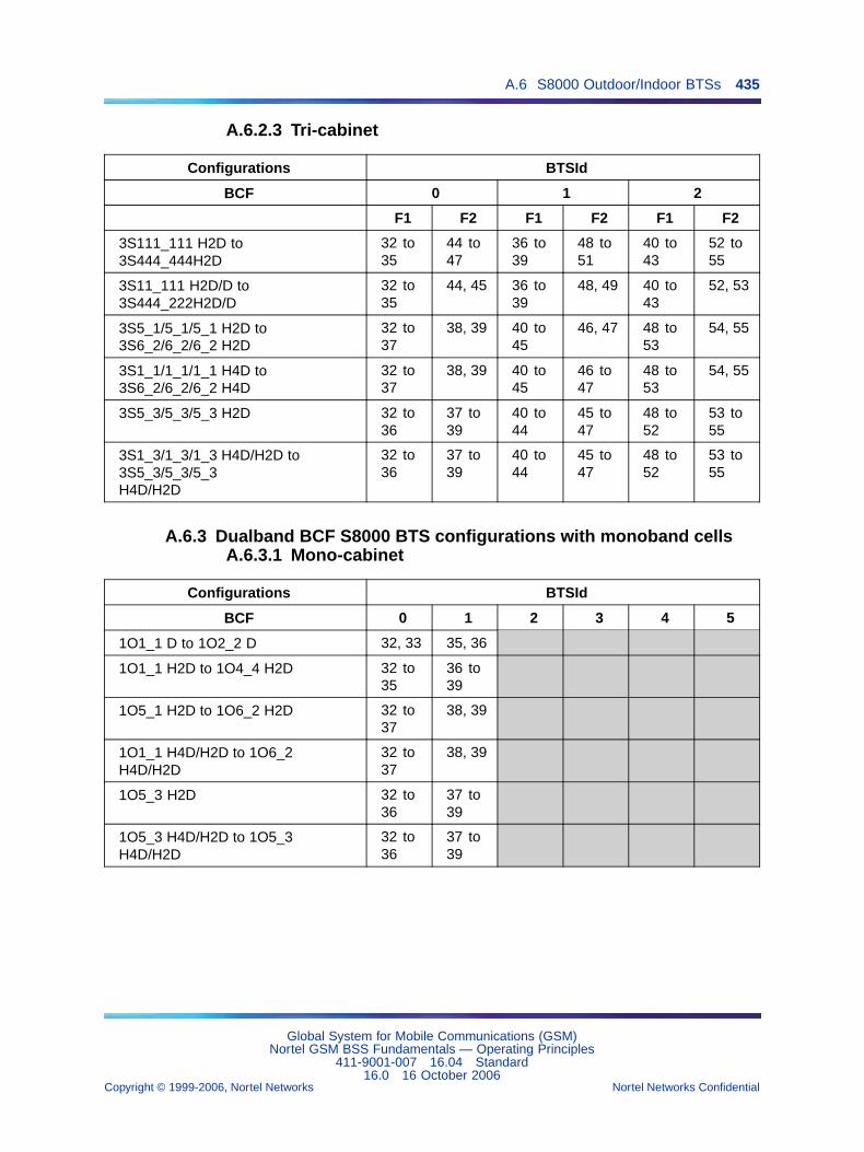
A.6 S8000 Outdoor/Indoor BTSs 435
A.6.2.3 Tri-cabinet
Configurations BTSId
BCF 0 1 2
F1 F2 F1 F2 F1 F2
3S111_111 H2D to3S444_444H2D
32 to35
44 to47
36 to39
48 to51
40 to43
52 to55
3S11_111 H2D/D to3S444_222H2D/D
32 to35
44, 45 36 to39
48, 49 40 to43
52, 53
3S5_1/5_1/5_1 H2D to3S6_2/6_2/6_2 H2D
32 to37
38, 39 40 to45
46, 47 48 to53
54, 55
3S1_1/1_1/1_1 H4D to3S6_2/6_2/6_2 H4D
32 to37
38, 39 40 to45
46 to47
48 to53
54, 55
3S5_3/5_3/5_3 H2D 32 to36
37 to39
40 to44
45 to47
48 to52
53 to55
3S1_3/1_3/1_3 H4D/H2D to3S5_3/5_3/5_3H4D/H2D
32 to36
37 to39
40 to44
45 to47
48 to52
53 to55
A.6.3 Dualband BCF S8000 BTS configurations with monoband cellsA.6.3.1 Mono-cabinet
Configurations BTSId
BCF 0 1 2 3 4 5
1O1_1 D to 1O2_2 D 32, 33 35, 36
1O1_1 H2D to 1O4_4 H2D 32 to35
36 to39
1O5_1 H2D to 1O6_2 H2D 32 to37
38, 39
1O1_1 H4D/H2D to 1O6_2H4D/H2D
32 to37
38, 39
1O5_3 H2D 32 to36
37 to39
1O5_3 H4D/H2D to 1O5_3H4D/H2D
32 to36
37 to39
Global System for Mobile Communications (GSM)Nortel GSM BSS Fundamentals — Operating Principles
411-9001-007 16.04 Standard16.0 16 October 2006
Copyright © 1999-2006, Nortel Networks Nortel Networks Confidential
.
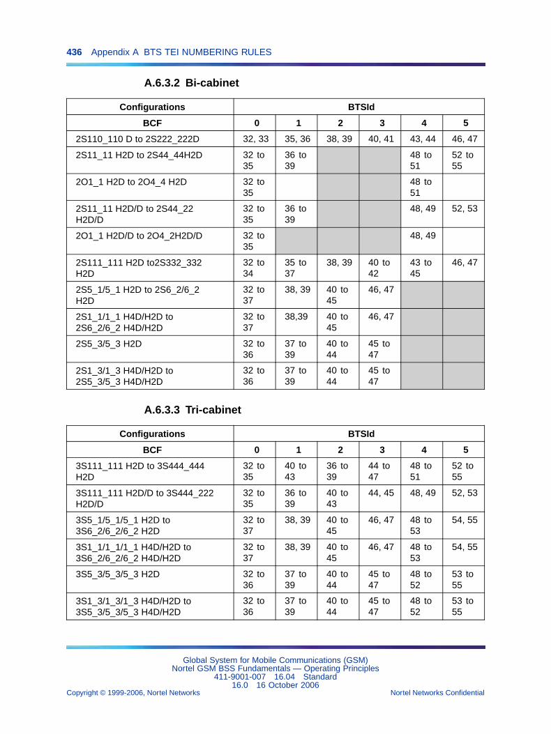
436 Appendix A BTS TEI NUMBERING RULES
A.6.3.2 Bi-cabinet
Configurations BTSId
BCF 0 1 2 3 4 5
2S110_110 D to 2S222_222D 32, 33 35, 36 38, 39 40, 41 43, 44 46, 47
2S11_11 H2D to 2S44_44H2D 32 to35
36 to39
48 to51
52 to55
2O1_1 H2D to 2O4_4 H2D 32 to35
48 to51
2S11_11 H2D/D to 2S44_22H2D/D
32 to35
36 to39
48, 49 52, 53
2O1_1 H2D/D to 2O4_2H2D/D 32 to35
48, 49
2S111_111 H2D to2S332_332H2D
32 to34
35 to37
38, 39 40 to42
43 to45
46, 47
2S5_1/5_1 H2D to 2S6_2/6_2H2D
32 to37
38, 39 40 to45
46, 47
2S1_1/1_1 H4D/H2D to2S6_2/6_2 H4D/H2D
32 to37
38,39 40 to45
46, 47
2S5_3/5_3 H2D 32 to36
37 to39
40 to44
45 to47
2S1_3/1_3 H4D/H2D to2S5_3/5_3 H4D/H2D
32 to36
37 to39
40 to44
45 to47
A.6.3.3 Tri-cabinet
Configurations BTSId
BCF 0 1 2 3 4 5
3S111_111 H2D to 3S444_444H2D
32 to35
40 to43
36 to39
44 to47
48 to51
52 to55
3S111_111 H2D/D to 3S444_222H2D/D
32 to35
36 to39
40 to43
44, 45 48, 49 52, 53
3S5_1/5_1/5_1 H2D to3S6_2/6_2/6_2 H2D
32 to37
38, 39 40 to45
46, 47 48 to53
54, 55
3S1_1/1_1/1_1 H4D/H2D to3S6_2/6_2/6_2 H4D/H2D
32 to37
38, 39 40 to45
46, 47 48 to53
54, 55
3S5_3/5_3/5_3 H2D 32 to36
37 to39
40 to44
45 to47
48 to52
53 to55
3S1_3/1_3/1_3 H4D/H2D to3S5_3/5_3/5_3 H4D/H2D
32 to36
37 to39
40 to44
45 to47
48 to52
53 to55
Global System for Mobile Communications (GSM)Nortel GSM BSS Fundamentals — Operating Principles
411-9001-007 16.04 Standard16.0 16 October 2006
Copyright © 1999-2006, Nortel Networks Nortel Networks Confidential
.
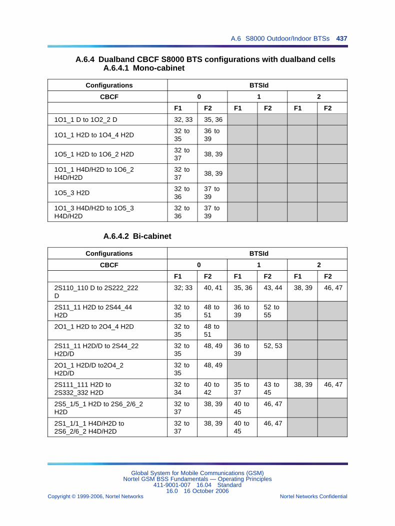
A.6 S8000 Outdoor/Indoor BTSs 437
A.6.4 Dualband CBCF S8000 BTS configurations with dualband cellsA.6.4.1 Mono-cabinet
Configurations BTSId
CBCF 0 1 2
F1 F2 F1 F2 F1 F2
1O1_1 D to 1O2_2 D 32, 33 35, 36
1O1_1 H2D to 1O4_4 H2D32 to35
36 to39
1O5_1 H2D to 1O6_2 H2D32 to37
38, 39
1O1_1 H4D/H2D to 1O6_2H4D/H2D
32 to37
38, 39
1O5_3 H2D32 to36
37 to39
1O1_3 H4D/H2D to 1O5_3H4D/H2D
32 to36
37 to39
A.6.4.2 Bi-cabinet
Configurations BTSId
CBCF 0 1 2
F1 F2 F1 F2 F1 F2
2S110_110 D to 2S222_222D
32; 33 40, 41 35, 36 43, 44 38, 39 46, 47
2S11_11 H2D to 2S44_44H2D
32 to35
48 to51
36 to39
52 to55
2O1_1 H2D to 2O4_4 H2D 32 to35
48 to51
2S11_11 H2D/D to 2S44_22H2D/D
32 to35
48, 49 36 to39
52, 53
2O1_1 H2D/D to2O4_2H2D/D
32 to35
48, 49
2S111_111 H2D to2S332_332 H2D
32 to34
40 to42
35 to37
43 to45
38, 39 46, 47
2S5_1/5_1 H2D to 2S6_2/6_2H2D
32 to37
38, 39 40 to45
46, 47
2S1_1/1_1 H4D/H2D to2S6_2/6_2 H4D/H2D
32 to37
38, 39 40 to45
46, 47
Global System for Mobile Communications (GSM)Nortel GSM BSS Fundamentals — Operating Principles
411-9001-007 16.04 Standard16.0 16 October 2006
Copyright © 1999-2006, Nortel Networks Nortel Networks Confidential
.
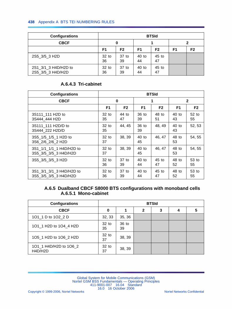
438 Appendix A BTS TEI NUMBERING RULES
Configurations BTSId
CBCF 0 1 2
F1 F2 F1 F2 F1 F2
2S5_3/5_3 H2D 32 to36
37 to39
40 to44
45 to47
2S1_3/1_3 H4D/H2D to2S5_3/5_3 H4D/H2D
32 to36
37 to39
40 to44
45 to47
A.6.4.3 Tri-cabinet
Configurations BTSId
CBCF 0 1 2
F1 F2 F1 F2 F1 F2
3S111_111 H2D to3S444_444 H2D
32 to35
44 to47
36 to39
48 to51
40 to43
52 to55
3S111_111 H2D/D to3S444_222 H2D/D
32 to35
44, 45 36 to39
48, 49 40 to43
52, 53
3S5_1/5_1/5_1 H2D to3S6_2/6_2/6_2 H2D
32 to37
38, 39 40 to45
46, 47 48 to53
54, 55
3S1_1/1_1/1_1 H4D/H2D to3S5_3/5_3/5_3 H4D/H2D
32 to37
38, 39 40 to45
46, 47 48 to53
54, 55
3S5_3/5_3/5_3 H2D 32 to36
37 to39
40 to44
45 to47
48 to52
53 to55
3S1_3/1_3/1_3 H4D/H2D to3S5_3/5_3/5_3 H4D/H2D
32 to36
37 to39
40 to44
45 to47
48 to52
53 to55
A.6.5 Dualband CBCF S8000 BTS configurations with monoband cellsA.6.5.1 Mono-cabinet
Configurations BTSId
CBCF 0 1 2 3 4 5
1O1_1 D to 1O2_2 D 32, 33 35, 36
1O1_1 H2D to 1O4_4 H2D32 to35
36 to39
1O5_1 H2D to 1O6_2 H2D32 to37
38, 39
1O1_1 H4D/H2D to 1O6_2H4D/H2D
32 to37
38, 39
Global System for Mobile Communications (GSM)Nortel GSM BSS Fundamentals — Operating Principles
411-9001-007 16.04 Standard16.0 16 October 2006
Copyright © 1999-2006, Nortel Networks Nortel Networks Confidential
.
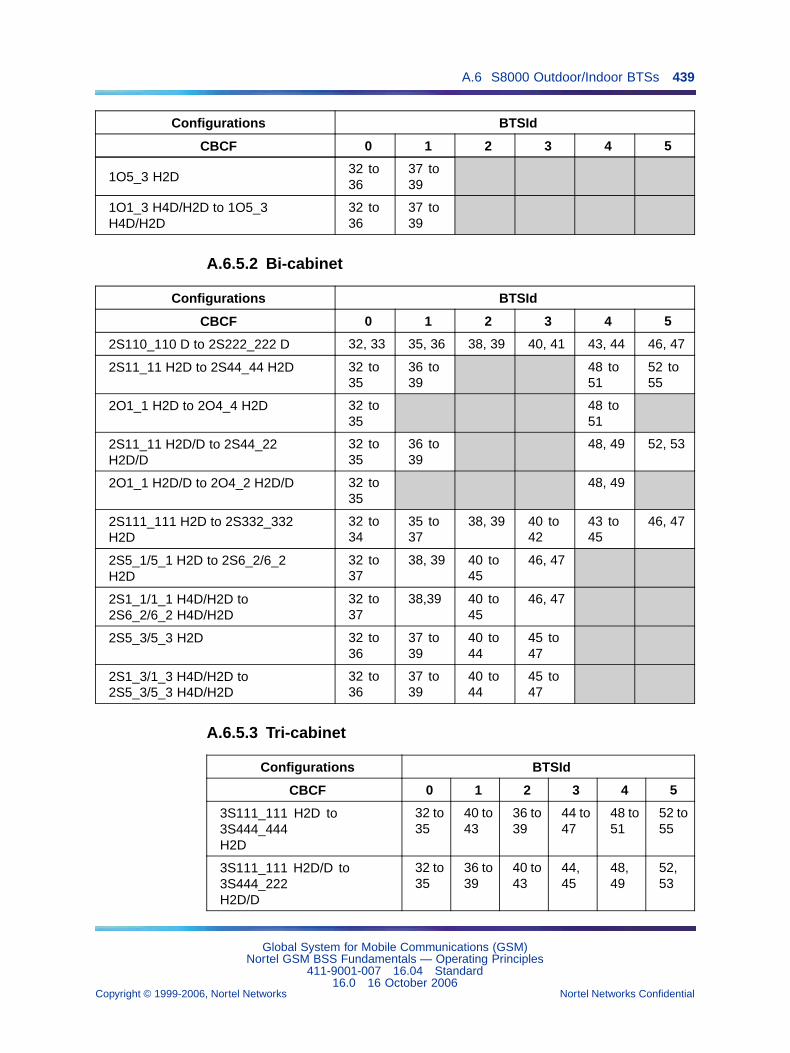
A.6 S8000 Outdoor/Indoor BTSs 439
Configurations BTSId
CBCF 0 1 2 3 4 5
1O5_3 H2D32 to36
37 to39
1O1_3 H4D/H2D to 1O5_3H4D/H2D
32 to36
37 to39
A.6.5.2 Bi-cabinet
Configurations BTSId
CBCF 0 1 2 3 4 5
2S110_110 D to 2S222_222 D 32, 33 35, 36 38, 39 40, 41 43, 44 46, 47
2S11_11 H2D to 2S44_44 H2D 32 to35
36 to39
48 to51
52 to55
2O1_1 H2D to 2O4_4 H2D 32 to35
48 to51
2S11_11 H2D/D to 2S44_22H2D/D
32 to35
36 to39
48, 49 52, 53
2O1_1 H2D/D to 2O4_2 H2D/D 32 to35
48, 49
2S111_111 H2D to 2S332_332H2D
32 to34
35 to37
38, 39 40 to42
43 to45
46, 47
2S5_1/5_1 H2D to 2S6_2/6_2H2D
32 to37
38, 39 40 to45
46, 47
2S1_1/1_1 H4D/H2D to2S6_2/6_2 H4D/H2D
32 to37
38,39 40 to45
46, 47
2S5_3/5_3 H2D 32 to36
37 to39
40 to44
45 to47
2S1_3/1_3 H4D/H2D to2S5_3/5_3 H4D/H2D
32 to36
37 to39
40 to44
45 to47
A.6.5.3 Tri-cabinet
Configurations BTSId
CBCF 0 1 2 3 4 5
3S111_111 H2D to3S444_444H2D
32 to35
40 to43
36 to39
44 to47
48 to51
52 to55
3S111_111 H2D/D to3S444_222H2D/D
32 to35
36 to39
40 to43
44,45
48,49
52,53
Global System for Mobile Communications (GSM)Nortel GSM BSS Fundamentals — Operating Principles
411-9001-007 16.04 Standard16.0 16 October 2006
Copyright © 1999-2006, Nortel Networks Nortel Networks Confidential
.
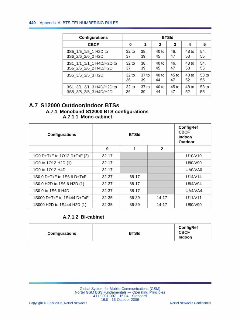
440 Appendix A BTS TEI NUMBERING RULES
Configurations BTSId
CBCF 0 1 2 3 4 5
3S5_1/5_1/5_1 H2D to3S6_2/6_2/6_2 H2D
32 to37
38,39
40 to45
46,47
48 to53
54,55
3S1_1/1_1/1_1 H4D/H2D to3S6_2/6_2/6_2 H4D/H2D
32 to37
38,39
40 to45
46,47
48 to53
54,55
3S5_3/5_3/5_3 H2D 32 to36
37 to39
40 to44
45 to47
48 to52
53 to55
3S1_3/1_3/1_3 H4D/H2D to3S5_3/5_3/5_3 H4D/H2D
32 to36
37 to39
40 to44
45 to47
48 to52
53 to55
A.7 S12000 Outdoor/Indoor BTSsA.7.1 Monoband S12000 BTS configurations
A.7.1.1 Mono-cabinet
Configurations BTSId
ConfigRefCBCFIndoor/Outdoor
0 1 2
1O0 D+TxF to 1O12 D+TxF (2) 32-17 U10/V10
1O0 to 1O12 H2D (1) 32-17 U90/V90
1O0 to 1O12 H4D 32-17 UA0/VA0
1S0 0 D+TxF to 1S6 6 D+TxF 32-37 38-17 U14/V14
1S0 0 H2D to 1S6 6 H2D (1) 32-37 38-17 U94/V94
1S0 0 to 1S6 6 H4D 32-37 38-17 UA4/VA4
1S000 D+TxF to 1S444 D+TxF 32-35 36-39 14-17 U11/V11
1S000 H2D to 1S444 H2D (1) 32-35 36-39 14-17 U90/V90
A.7.1.2 Bi-cabinet
Configurations BTSIdConfigRefCBCFIndoor/
Global System for Mobile Communications (GSM)Nortel GSM BSS Fundamentals — Operating Principles
411-9001-007 16.04 Standard16.0 16 October 2006
Copyright © 1999-2006, Nortel Networks Nortel Networks Confidential
.
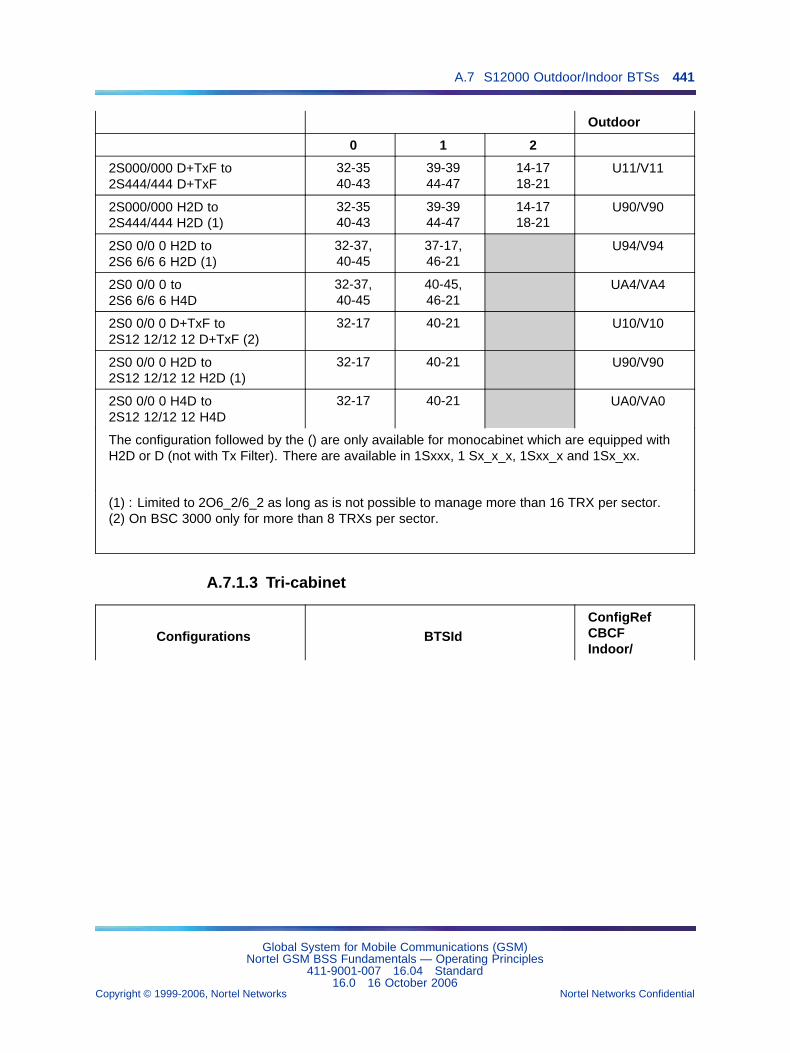
A.7 S12000 Outdoor/Indoor BTSs 441
Outdoor
0 1 2
2S000/000 D+TxF to2S444/444 D+TxF
32-3540-43
39-3944-47
14-1718-21
U11/V11
2S000/000 H2D to2S444/444 H2D (1)
32-3540-43
39-3944-47
14-1718-21
U90/V90
2S0 0/0 0 H2D to2S6 6/6 6 H2D (1)
32-37,40-45
37-17,46-21
U94/V94
2S0 0/0 0 to2S6 6/6 6 H4D
32-37,40-45
40-45,46-21
UA4/VA4
2S0 0/0 0 D+TxF to2S12 12/12 12 D+TxF (2)
32-17 40-21 U10/V10
2S0 0/0 0 H2D to2S12 12/12 12 H2D (1)
32-17 40-21 U90/V90
2S0 0/0 0 H4D to2S12 12/12 12 H4D
32-17 40-21 UA0/VA0
The configuration followed by the () are only available for monocabinet which are equipped withH2D or D (not with Tx Filter). There are available in 1Sxxx, 1 Sx_x_x, 1Sxx_x and 1Sx_xx.
(1) : Limited to 2O6_2/6_2 as long as is not possible to manage more than 16 TRX per sector.(2) On BSC 3000 only for more than 8 TRXs per sector.
A.7.1.3 Tri-cabinet
Configurations BTSIdConfigRefCBCFIndoor/
Global System for Mobile Communications (GSM)Nortel GSM BSS Fundamentals — Operating Principles
411-9001-007 16.04 Standard16.0 16 October 2006
Copyright © 1999-2006, Nortel Networks Nortel Networks Confidential
.
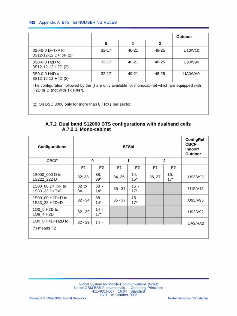
442 Appendix A BTS TEI NUMBERING RULES
Outdoor
0 1 2
3S0-0-0 D+TxF to3S12-12-12 D+TxF (2)
32-17 40-21 48-25 U10/V10
3S0-0-0 H2D to3S12-12-12 H2D (2)
32-17 40-21 48-25 U90/V90
3S0-0-0 H4D to3S12-12-12 H4D (2)
32-17 40-21 48-25 UA0/VA0
The configuration followed by the () are only available for monocabinet which are equipped withH2D or D (not with Tx Filter).
(2) On BSC 3000 only for more than 8 TRXs per sector.
A.7.2 Dual band S12000 BTS configurations with dualband cellsA.7.2.1 Mono-cabinet
Configurations BTSId
ConfigRefCBCFIndoor/Outdoor
CBCF 0 1 2
F1 F2 F1 F2 F1 F2
1S000_000 D to1S222_222 D
32; 3338,39*
34, 3514,15*
36, 3716,17*
U93/V93
1S00_00 D+TxF to1S33_33 D+TxF
32 to34
38 -14*
35 - 3715 -17*
U15/V15
1S00_00 H2D+D to1S33_33 H2D+D
32 - 3438 -14*
35 - 3715 -17*
U95/V95
1O0_0 H2D to1O8_4 H2D
32 - 3914 -17*
U92/V92
1O0_0 H4D+H2D to 32 - 39 14 - UA2/VA2(*) means F2
Global System for Mobile Communications (GSM)Nortel GSM BSS Fundamentals — Operating Principles
411-9001-007 16.04 Standard16.0 16 October 2006
Copyright © 1999-2006, Nortel Networks Nortel Networks Confidential
.
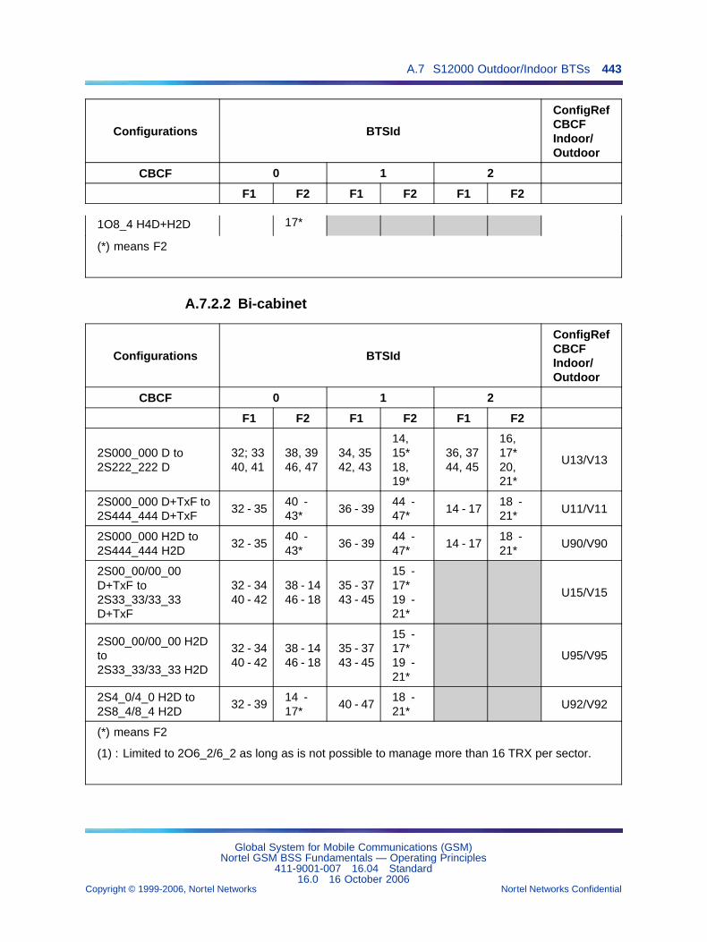
A.7 S12000 Outdoor/Indoor BTSs 443
Configurations BTSId
ConfigRefCBCFIndoor/Outdoor
CBCF 0 1 2
F1 F2 F1 F2 F1 F2
1O8_4 H4D+H2D 17*
(*) means F2
A.7.2.2 Bi-cabinet
Configurations BTSId
ConfigRefCBCFIndoor/Outdoor
CBCF 0 1 2
F1 F2 F1 F2 F1 F2
2S000_000 D to2S222_222 D
32; 3340, 41
38, 3946, 47
34, 3542, 43
14,15*18,19*
36, 3744, 45
16,17*20,21*
U13/V13
2S000_000 D+TxF to2S444_444 D+TxF
32 - 3540 -43*
36 - 3944 -47*
14 - 1718 -21*
U11/V11
2S000_000 H2D to2S444_444 H2D
32 - 3540 -43*
36 - 3944 -47*
14 - 1718 -21*
U90/V90
2S00_00/00_00D+TxF to2S33_33/33_33D+TxF
32 - 3440 - 42
38 - 1446 - 18
35 - 3743 - 45
15 -17*19 -21*
U15/V15
2S00_00/00_00 H2Dto2S33_33/33_33 H2D
32 - 3440 - 42
38 - 1446 - 18
35 - 3743 - 45
15 -17*19 -21*
U95/V95
2S4_0/4_0 H2D to2S8_4/8_4 H2D
32 - 3914 -17*
40 - 4718 -21*
U92/V92
(*) means F2
(1) : Limited to 2O6_2/6_2 as long as is not possible to manage more than 16 TRX per sector.
Global System for Mobile Communications (GSM)Nortel GSM BSS Fundamentals — Operating Principles
411-9001-007 16.04 Standard16.0 16 October 2006
Copyright © 1999-2006, Nortel Networks Nortel Networks Confidential
.
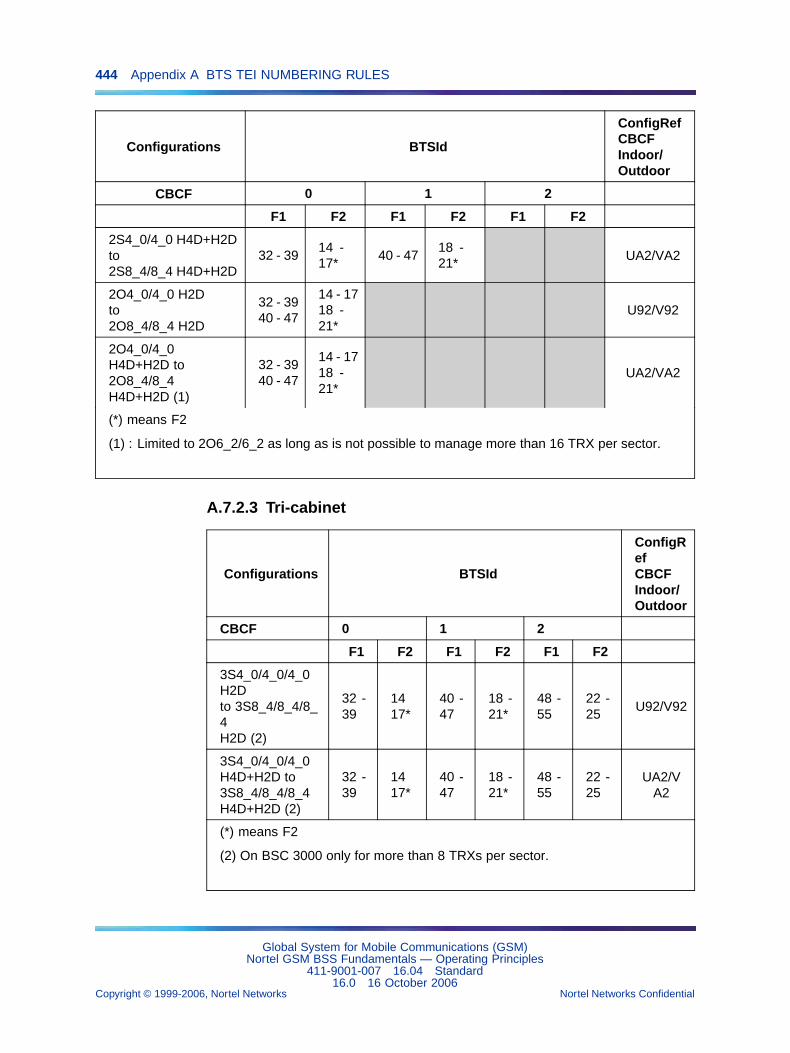
444 Appendix A BTS TEI NUMBERING RULES
Configurations BTSId
ConfigRefCBCFIndoor/Outdoor
CBCF 0 1 2
F1 F2 F1 F2 F1 F2
2S4_0/4_0 H4D+H2Dto2S8_4/8_4 H4D+H2D
32 - 3914 -17*
40 - 4718 -21*
UA2/VA2
2O4_0/4_0 H2Dto2O8_4/8_4 H2D
32 - 3940 - 47
14 - 1718 -21*
U92/V92
2O4_0/4_0H4D+H2D to2O8_4/8_4H4D+H2D (1)
32 - 3940 - 47
14 - 1718 -21*
UA2/VA2
(*) means F2
(1) : Limited to 2O6_2/6_2 as long as is not possible to manage more than 16 TRX per sector.
A.7.2.3 Tri-cabinet
Configurations BTSId
ConfigRefCBCFIndoor/Outdoor
CBCF 0 1 2
F1 F2 F1 F2 F1 F2
3S4_0/4_0/4_0H2Dto 3S8_4/8_4/8_4H2D (2)
32 -39
1417*
40 -47
18 -21*
48 -55
22 -25
U92/V92
3S4_0/4_0/4_0H4D+H2D to3S8_4/8_4/8_4H4D+H2D (2)
32 -39
1417*
40 -47
18 -21*
48 -55
22 -25
UA2/VA2
(*) means F2
(2) On BSC 3000 only for more than 8 TRXs per sector.
Global System for Mobile Communications (GSM)Nortel GSM BSS Fundamentals — Operating Principles
411-9001-007 16.04 Standard16.0 16 October 2006
Copyright © 1999-2006, Nortel Networks Nortel Networks Confidential
.
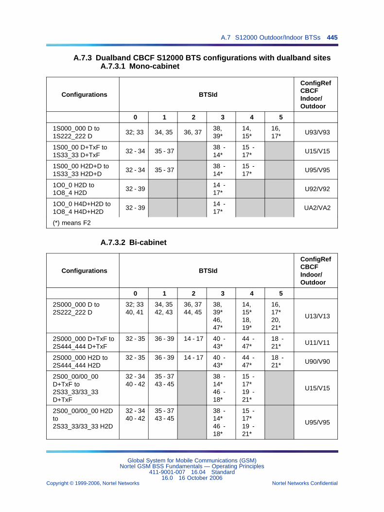
A.7 S12000 Outdoor/Indoor BTSs 445
A.7.3 Dualband CBCF S12000 BTS configurations with dualband sitesA.7.3.1 Mono-cabinet
Configurations BTSId
ConfigRefCBCFIndoor/Outdoor
0 1 2 3 4 5
1S000_000 D to1S222_222 D
32; 33 34, 35 36, 3738,39*
14,15*
16,17*
U93/V93
1S00_00 D+TxF to1S33_33 D+TxF
32 - 34 35 - 3738 -14*
15 -17*
U15/V15
1S00_00 H2D+D to1S33_33 H2D+D
32 - 34 35 - 3738 -14*
15 -17*
U95/V95
1O0_0 H2D to1O8_4 H2D
32 - 3914 -17*
U92/V92
1O0_0 H4D+H2D to1O8_4 H4D+H2D
32 - 3914 -17*
UA2/VA2
(*) means F2
A.7.3.2 Bi-cabinet
Configurations BTSId
ConfigRefCBCFIndoor/Outdoor
0 1 2 3 4 5
2S000_000 D to2S222_222 D
32; 3340, 41
34, 3542, 43
36, 3744, 45
38,39*46,47*
14,15*18,19*
16,17*20,21*
U13/V13
2S000_000 D+TxF to2S444_444 D+TxF
32 - 35 36 - 39 14 - 17 40 -43*
44 -47*
18 -21*
U11/V11
2S000_000 H2D to2S444_444 H2D
32 - 35 36 - 39 14 - 17 40 -43*
44 -47*
18 -21* U90/V90
2S00_00/00_00D+TxF to2S33_33/33_33D+TxF
32 - 3440 - 42
35 - 3743 - 45
38 -14*46 -18*
15 -17*19 -21*
U15/V15
2S00_00/00_00 H2Dto2S33_33/33_33 H2D
32 - 3440 - 42
35 - 3743 - 45
38 -14*46 -18*
15 -17*19 -21*
U95/V95
Global System for Mobile Communications (GSM)Nortel GSM BSS Fundamentals — Operating Principles
411-9001-007 16.04 Standard16.0 16 October 2006
Copyright © 1999-2006, Nortel Networks Nortel Networks Confidential
.
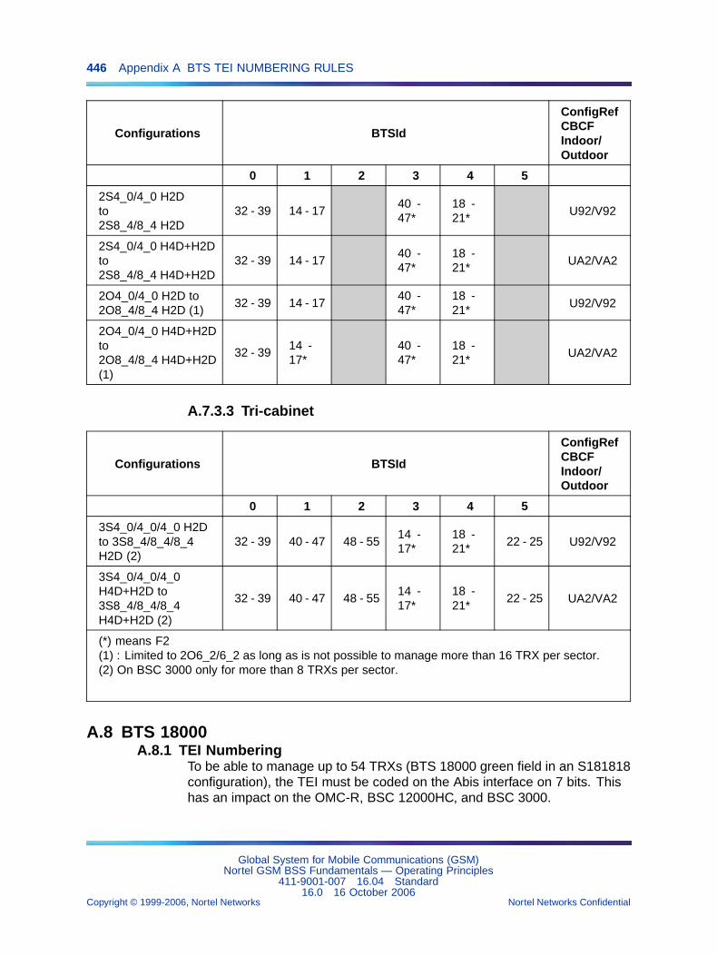
446 Appendix A BTS TEI NUMBERING RULES
Configurations BTSId
ConfigRefCBCFIndoor/Outdoor
0 1 2 3 4 5
2S4_0/4_0 H2Dto2S8_4/8_4 H2D
32 - 39 14 - 1740 -47*
18 -21*
U92/V92
2S4_0/4_0 H4D+H2Dto2S8_4/8_4 H4D+H2D
32 - 39 14 - 1740 -47*
18 -21*
UA2/VA2
2O4_0/4_0 H2D to2O8_4/8_4 H2D (1)
32 - 39 14 - 1740 -47*
18 -21*
U92/V92
2O4_0/4_0 H4D+H2Dto2O8_4/8_4 H4D+H2D(1)
32 - 3914 -17*
40 -47*
18 -21*
UA2/VA2
A.7.3.3 Tri-cabinet
Configurations BTSId
ConfigRefCBCFIndoor/Outdoor
0 1 2 3 4 5
3S4_0/4_0/4_0 H2Dto 3S8_4/8_4/8_4H2D (2)
32 - 39 40 - 47 48 - 5514 -17*
18 -21*
22 - 25 U92/V92
3S4_0/4_0/4_0H4D+H2D to3S8_4/8_4/8_4H4D+H2D (2)
32 - 39 40 - 47 48 - 5514 -17*
18 -21*
22 - 25 UA2/VA2
(*) means F2(1) : Limited to 2O6_2/6_2 as long as is not possible to manage more than 16 TRX per sector.(2) On BSC 3000 only for more than 8 TRXs per sector.
A.8 BTS 18000A.8.1 TEI Numbering
To be able to manage up to 54 TRXs (BTS 18000 green field in an S181818configuration), the TEI must be coded on the Abis interface on 7 bits. Thishas an impact on the OMC-R, BSC 12000HC, and BSC 3000.
Global System for Mobile Communications (GSM)Nortel GSM BSS Fundamentals — Operating Principles
411-9001-007 16.04 Standard16.0 16 October 2006
Copyright © 1999-2006, Nortel Networks Nortel Networks Confidential
.
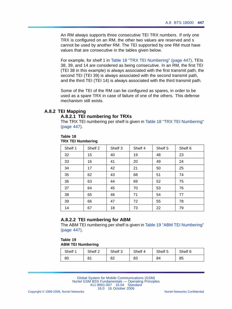
A.8 BTS 18000 447
An RM always supports three consecutive TEI TRX numbers. If only oneTRX is configured on an RM, the other two values are reserved and scannot be used by another RM. The TEI supported by one RM must havevalues that are consecutive in the tables given below.
For example, for shelf 1 in Table 18 "TRX TEI Numbering" (page 447), TEIs38, 39, and 14 are considered as being consecutive. In an RM, the first TEI(TEI 38 in this example) is always associated with the first transmit path, thesecond TEI (TEI 39) is always associated with the second transmit path,and the third TEI (TEI 14) is always associated with the third transmit path.
Some of the TEI of the RM can be configured as spares, in order to beused as a spare TRX in case of failure of one of the others. This defensemechanism still exists.
A.8.2 TEI MappingA.8.2.1 TEI numbering for TRXsThe TRX TEI numbering per shelf is given in Table 18 "TRX TEI Numbering"(page 447).
Table 18TRX TEI Numbering
Shelf 1 Shelf 2 Shelf 3 Shelf 4 Shelf 5 Shelf 6
32 15 40 19 48 23
33 16 41 20 49 24
34 17 42 21 50 25
35 62 43 68 51 74
36 63 44 69 52 75
37 64 45 70 53 76
38 65 46 71 54 77
39 66 47 72 55 78
14 67 18 73 22 79
A.8.2.2 TEI numbering for ABMThe ABM TEI numbering per shelf is given in Table 19 "ABM TEI Numbering"(page 447).
Table 19ABM TEI Numbering
Shelf 1 Shelf 2 Shelf 3 Shelf 4 Shelf 5 Shelf 6
80 81 82 83 84 85
Global System for Mobile Communications (GSM)Nortel GSM BSS Fundamentals — Operating Principles
411-9001-007 16.04 Standard16.0 16 October 2006
Copyright © 1999-2006, Nortel Networks Nortel Networks Confidential
.
448 Appendix A BTS TEI NUMBERING RULES
A.8.2.3 Other TEIsTEI 0 to 9 are site TEIs.
If SPMs are connected to the ICM through a LAPD link, TEIs 86 and 87are used.
If IFMs are connected to the ICM through a LAPD link, TEIs 88 and 89are used.
A.8.2.4 Spare TRXsSpare TRXs can be defined exactly the same way they are onS8000/S12000 BTSs.
The spare TRXs are part of the BTS configuration. All radio and couplingmodules necessary for the spare TRX are installed and connected. Eachspare TRX is created on the OMC-R and is dedicated to a given cell. Thespare TRX are available for TDMA defenses managed by the BSC throughthe TDMA reconfiguration function.
A.8.3 Location of shelvesA.8.3.1 Indoor BTS 18000Shelves 1 and 2 are in the main cabinet (shelf 1 is upper and shelf 2 islower); shelves 3 and 4 are in the first extension (shelf 3 is upper and shelf4 is lower); shelves 5 and 6 are in the second extension (shelf 5 is upperand shelf 6 is lower).
A.8.3.2 Outdoor BTS 18000:Shelves 1 and 2 are in the main cabinet (shelf 1 is left and shelf 2 is right);shelves 3 and 4 are in the first extension (shelf 3 is left and shelf 4 is right);shelves 5 and 6 are in the second extension (shelf 5 is left and shelf 6 isright).
Global System for Mobile Communications (GSM)Nortel GSM BSS Fundamentals — Operating Principles
411-9001-007 16.04 Standard16.0 16 October 2006
Copyright © 1999-2006, Nortel Networks Nortel Networks Confidential
.
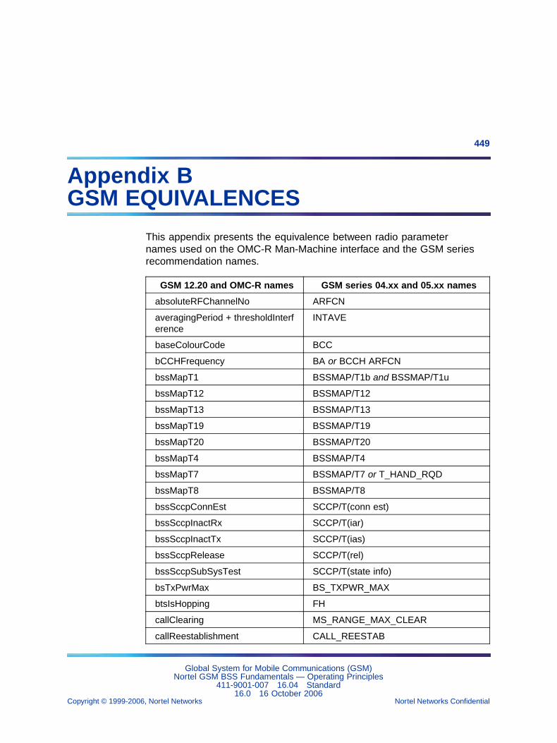
449
Appendix BGSM EQUIVALENCES
This appendix presents the equivalence between radio parameternames used on the OMC-R Man-Machine interface and the GSM seriesrecommendation names.
GSM 12.20 and OMC-R names GSM series 04.xx and 05.xx names
absoluteRFChannelNo ARFCN
averagingPeriod + thresholdInterference
INTAVE
baseColourCode BCC
bCCHFrequency BA or BCCH ARFCN
bssMapT1 BSSMAP/T1b and BSSMAP/T1u
bssMapT12 BSSMAP/T12
bssMapT13 BSSMAP/T13
bssMapT19 BSSMAP/T19
bssMapT20 BSSMAP/T20
bssMapT4 BSSMAP/T4
bssMapT7 BSSMAP/T7 or T_HAND_RQD
bssMapT8 BSSMAP/T8
bssSccpConnEst SCCP/T(conn est)
bssSccpInactRx SCCP/T(iar)
bssSccpInactTx SCCP/T(ias)
bssSccpRelease SCCP/T(rel)
bssSccpSubSysTest SCCP/T(state info)
bsTxPwrMax BS_TXPWR_MAX
btsIsHopping FH
callClearing MS_RANGE_MAX_CLEAR
callReestablishment CALL_REESTAB
Global System for Mobile Communications (GSM)Nortel GSM BSS Fundamentals — Operating Principles
411-9001-007 16.04 Standard16.0 16 October 2006
Copyright © 1999-2006, Nortel Networks Nortel Networks Confidential
.
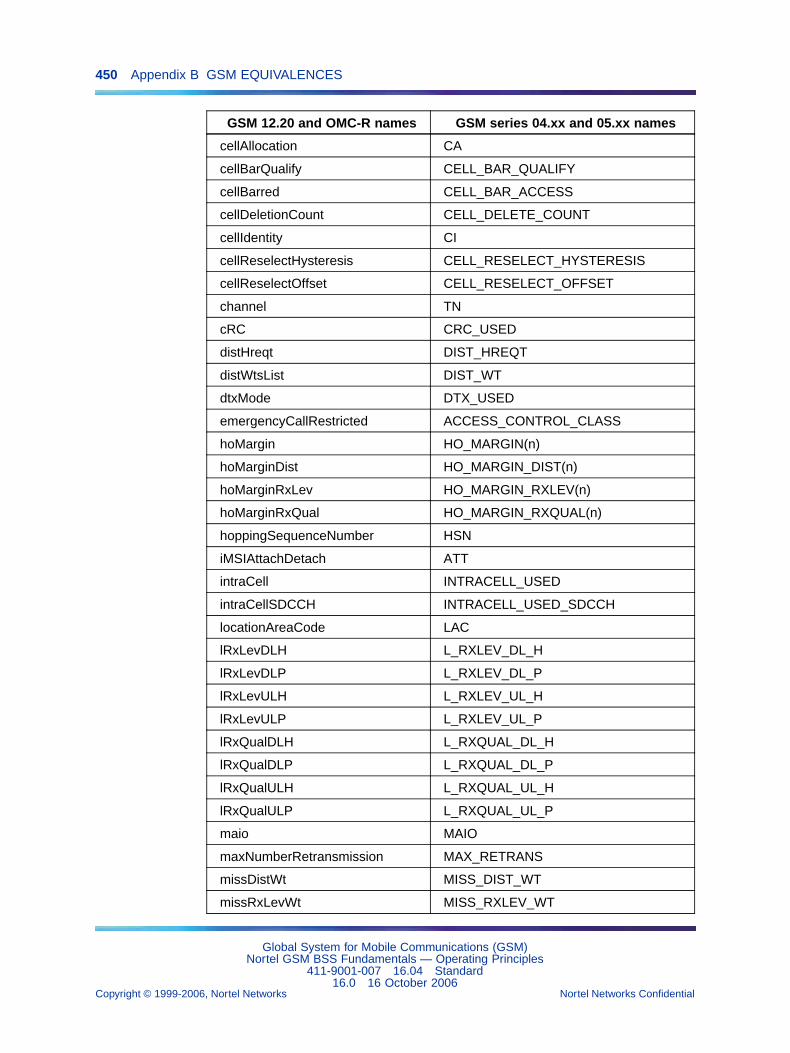
450 Appendix B GSM EQUIVALENCES
GSM 12.20 and OMC-R names GSM series 04.xx and 05.xx names
cellAllocation CA
cellBarQualify CELL_BAR_QUALIFY
cellBarred CELL_BAR_ACCESS
cellDeletionCount CELL_DELETE_COUNT
cellIdentity CI
cellReselectHysteresis CELL_RESELECT_HYSTERESIS
cellReselectOffset CELL_RESELECT_OFFSET
channel TN
cRC CRC_USED
distHreqt DIST_HREQT
distWtsList DIST_WT
dtxMode DTX_USED
emergencyCallRestricted ACCESS_CONTROL_CLASS
hoMargin HO_MARGIN(n)
hoMarginDist HO_MARGIN_DIST(n)
hoMarginRxLev HO_MARGIN_RXLEV(n)
hoMarginRxQual HO_MARGIN_RXQUAL(n)
hoppingSequenceNumber HSN
iMSIAttachDetach ATT
intraCell INTRACELL_USED
intraCellSDCCH INTRACELL_USED_SDCCH
locationAreaCode LAC
lRxLevDLH L_RXLEV_DL_H
lRxLevDLP L_RXLEV_DL_P
lRxLevULH L_RXLEV_UL_H
lRxLevULP L_RXLEV_UL_P
lRxQualDLH L_RXQUAL_DL_H
lRxQualDLP L_RXQUAL_DL_P
lRxQualULH L_RXQUAL_UL_H
lRxQualULP L_RXQUAL_UL_P
maio MAIO
maxNumberRetransmission MAX_RETRANS
missDistWt MISS_DIST_WT
missRxLevWt MISS_RXLEV_WT
Global System for Mobile Communications (GSM)Nortel GSM BSS Fundamentals — Operating Principles
411-9001-007 16.04 Standard16.0 16 October 2006
Copyright © 1999-2006, Nortel Networks Nortel Networks Confidential
.
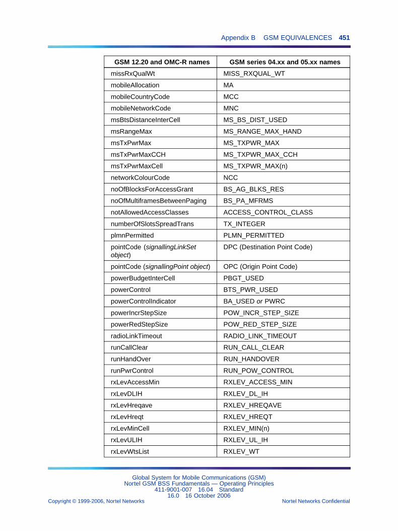
Appendix B GSM EQUIVALENCES 451
GSM 12.20 and OMC-R names GSM series 04.xx and 05.xx names
missRxQualWt MISS_RXQUAL_WT
mobileAllocation MA
mobileCountryCode MCC
mobileNetworkCode MNC
msBtsDistanceInterCell MS_BS_DIST_USED
msRangeMax MS_RANGE_MAX_HAND
msTxPwrMax MS_TXPWR_MAX
msTxPwrMaxCCH MS_TXPWR_MAX_CCH
msTxPwrMaxCell MS_TXPWR_MAX(n)
networkColourCode NCC
noOfBlocksForAccessGrant BS_AG_BLKS_RES
noOfMultiframesBetweenPaging BS_PA_MFRMS
notAllowedAccessClasses ACCESS_CONTROL_CLASS
numberOfSlotsSpreadTrans TX_INTEGER
plmnPermitted PLMN_PERMITTED
pointCode (signallingLinkSetobject)
DPC (Destination Point Code)
pointCode (signallingPoint object) OPC (Origin Point Code)
powerBudgetInterCell PBGT_USED
powerControl BTS_PWR_USED
powerControlIndicator BA_USED or PWRC
powerIncrStepSize POW_INCR_STEP_SIZE
powerRedStepSize POW_RED_STEP_SIZE
radioLinkTimeout RADIO_LINK_TIMEOUT
runCallClear RUN_CALL_CLEAR
runHandOver RUN_HANDOVER
runPwrControl RUN_POW_CONTROL
rxLevAccessMin RXLEV_ACCESS_MIN
rxLevDLIH RXLEV_DL_IH
rxLevHreqave RXLEV_HREQAVE
rxLevHreqt RXLEV_HREQT
rxLevMinCell RXLEV_MIN(n)
rxLevULIH RXLEV_UL_IH
rxLevWtsList RXLEV_WT
Global System for Mobile Communications (GSM)Nortel GSM BSS Fundamentals — Operating Principles
411-9001-007 16.04 Standard16.0 16 October 2006
Copyright © 1999-2006, Nortel Networks Nortel Networks Confidential
.
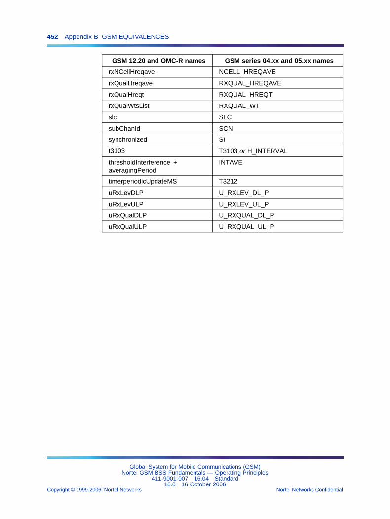
452 Appendix B GSM EQUIVALENCES
GSM 12.20 and OMC-R names GSM series 04.xx and 05.xx names
rxNCellHreqave NCELL_HREQAVE
rxQualHreqave RXQUAL_HREQAVE
rxQualHreqt RXQUAL_HREQT
rxQualWtsList RXQUAL_WT
slc SLC
subChanId SCN
synchronized SI
t3103 T3103 or H_INTERVAL
thresholdInterference +averagingPeriod
INTAVE
timerperiodicUpdateMS T3212
uRxLevDLP U_RXLEV_DL_P
uRxLevULP U_RXLEV_UL_P
uRxQualDLP U_RXQUAL_DL_P
uRxQualULP U_RXQUAL_UL_P
Global System for Mobile Communications (GSM)Nortel GSM BSS Fundamentals — Operating Principles
411-9001-007 16.04 Standard16.0 16 October 2006
Copyright © 1999-2006, Nortel Networks Nortel Networks Confidential
.

Global System for Mobile Communications (GSM)
Nortel GSM BSS Fundamentals — Operating PrinciplesCopyright © 1999-2006, Nortel NetworksAll Rights Reserved.
Publication: 411-9001-007Document status: StandardDocument version: 16.04Document date: 16 October 2006
For more information, please contact:
For all countries, except USA:
Documentation DepartmentParc d’activité de Magny-ChateaufortCHATEAUFORT78928 YVELINES CEDEX 9FRANCEEmail : [email protected] : (33) (1) 39-44-50-29
In the USA:
2221 Lakeside BoulevardRichardson TX 75082USATel: 1-800-4 NORTEL1-800-466-7838 or (972) 684-5935
Internet Address:
http://www.nortel.com
To provide feedback or report a problem in this document, go to www.nortel.com/documentfeedback
The information contained in this document is the property of Nortel Networks. Except as specifically authorized in writing by NortelNetworks, the holder of this document shall keep the information contained herein confidential and shall protect same in whole or inpart from disclosure and dissemination to third parties and use for evaluation, operation and maintenance purposes only.
You may not reproduce, represent, or download through any means, the information contained herein in any way or in any formwithout prior written consent of Nortel Networks.
Originated in France