Norrisown High Speed Line – Bryn Mawr Interlocking High Speed Line – Bryn Mawr Interlocking Apr...
47
SOUTHEASTERN PENNSYLVANIA TRANSPORTATION AUTHORITY SPECIFICATIONS FOR THE PROCUREMENT OF TRACKWORK MATERIALS: Norrisown High Speed Line – Bryn Mawr Interlocking Apr 1, 2016
Transcript of Norrisown High Speed Line – Bryn Mawr Interlocking High Speed Line – Bryn Mawr Interlocking Apr...

SOUTHEASTERN PENNSYLVANIA TRANSPORTATION AUTHORITY
SPECIFICATIONS FOR THE PROCUREMENT OF TRACKWORK MATERIALS:
Norrisown High Speed Line – Bryn Mawr Interlocking
Apr 1, 2016

TRACKWORK MATERIAL SPECIFICATIONS FOR BRYN MAWR INTERLOCKING
10/5/15 Page 1 of 15
PART 1 GENERAL
1.01 SUMMARY
A. This specification is intended to cover the requirements of the Southeastern Pennsylvania Transportation Authority, (SEPTA), for the manufacture of track work to be installed on the Norristown High Speed Line (NHSL) at Bryn Mawr.
B. This work includes all labor, material, equipment and tools necessary in order to design, manufacture, furnish, shop assemble, mark, inspect, disassemble, package, and deliver all track work materials including wood cross ties, for a complete layout of the following:
1. One (1) 115#RE interlocked standard left hand number 8 crossover at 13’0” track centers, including required long ties to support electrified contact rail insulators (third rail) for normal and crossover routes.
C. Prior to manufacturing, the Vendor must provide detailed shop drawings including a bill of materials for SEPTA approval.
D. After shop assembly, an outside inspection agency shall be hired by the Vendor, at no
additional cost to SEPTA to inspect all parts and the layout assembled in its entirety for fit, quality, and conformance to these specifications. The inspection agency must submit detailed inspection reports including color photographs, to SEPTA for approval prior to shipping. The inspection agency will also be responsible for production update reports to SEPTA. Any parts or dimensions not meeting the parameters of this specification or in the judgment of the inspector determined as defective shall be replaced and/or corrected by the Manufacturer at no additional cost to SEPTA.
E. Deliveries of all materials shall be within the time frame specified in these Contract Documents. Within seven days of award the Vendor must submit a detailed delivery schedule to SEPTA for approval. The schedule outline must include all dates and durations for: design, shop drawing submittals, manufacturing, assembly, inspections, and deliveries.
1.02 DRAWINGS
A. Contract Drawings are as follows. Standard drawings shall only be used for guidance in the development of manufacturers shop drawings. The drawings provided shall not be considered the final approved set and shall not be substituted for shop drawing submissions. Final shop drawings shall be tailored to suit the specific track geometry of each layout.
1. SEPTA Standard turnout data - 5W-29874

TRACKWORK MATERIAL SPECIFICATIONS FOR BRYN MAWR INTERLOCKING
10/5/15 Page 2 of 15
2. SEPTA Standard plans 639.00 for gage plates.
3. SEPTA Standard for Third Rail clearance drawing 2-W-37104
4. SEPTA X-Over Drawing 5-W-63718, for 3rd rail tie configuration 1.03 REFERENCE STANDARDS
A. A.R.E.M.A., Latest edition, “Portfolio of Track-work Plans” and “Manual For Railway Engineering”
B. American Society for Testing and Materials (ASTM), Standard Specifications:
1. A536, Ductile Iron Castings
2. A-66, Standard Specifications for Steel Screw Spikes
3. ASTM A-67, Standard Specifications for Low Carbon Steel Tie Plates
1.04 SUBMITTALS
A. All shop drawing transmittals shall be made using black and white paper prints, and electronic copies in Portable Document Format, PDF. All Computer Aided Drafting and Design, CADD, files used in creating final shop drawings shall be released to SEPTA at the completion of the project for final record keeping. All CADD files must be compatible with Microstation V8 or AutoCADD Version 2010.
B. The Vendor shall submit the following to SEPTA for approval before fabrication:
1. Shop Drawings:
a. All shop drawing dimension units shall be in feet and inches given to an accuracy of one sixteenth of an inch. Fractions of an inch less than one-sixteenth may be used where greater accuracy is required in fabrication.
b. Scaled shop drawings shall be provided for the following:
1) Switches, stock rails, and heel block assemblies for switches
2) All switch point details, plates, castings, heel blocks, switch rods, and other miscellaneous parts.
3) Switch rods and clips
4) Railbound manganese frogs.

TRACKWORK MATERIAL SPECIFICATIONS FOR BRYN MAWR INTERLOCKING
10/5/15 Page 3 of 15
5) Rail schedule including bending, and drilling sketches. Sketches must show rail and joint identifications, as marked during shop layout and matching those shown on the complete layout.
6) Timber layout and tie plate locations.
7) One complete layout, showing the track geometric data, and identifying all: rail lengths, switches, switch rods, frogs, rail joints, plates, and timbers. Lettering and numbering schemes must be used to identify joints, rails, and frogs. A rail schedule and a complete bill of materials must also be provided on the complete layout.
2. Manufacturers catalog cuts and data as necessary.
3. Inspection reports including color photographs of all switch points, frogs, and complete layouts assembled in their entirety.
4. Quality management systems certificates and/or procedures.
5. Product Data: Submit the procedure to be used in the depth hardening of frog and diamond castings.
6. Certificates and Reports:
a. Certificates of material compliance required by AREMA and this Specification.
b. Test reports of chemical analyses, Brinell hardness, and other tests required by A.R.E.M.A. and the Contract Documents.
c. Frog depth hardening results.
7. Submittal comments shall be returned from SEPTA to the Vendor within eight business days.
1.05 QUALITY ASSURANCE
A. All manufacturers shall be ISO 9001 certified, or have an alternate quality management system in place.
B. Manufacturers not ISO 9001 certified must provide documentation of their quality management system in place and submit this documentation to SEPTA for approval. This documentation must detail the following procedures:

TRACKWORK MATERIAL SPECIFICATIONS FOR BRYN MAWR INTERLOCKING
10/5/15 Page 4 of 15
1. Vendor surveillance (All subcontractors)
2. Drawing Control (changes)
3. Document Control
4. Inspection Procedures - in process and final
5. Production Test Requirements
6. Segregation and disposition of defective material and products.
7. Material and process control in plant, identifying critical control points.
8. Production "equipment" and "instrumentation" calibration, maintenance, and data recording.
9. Work procedures and instructions.
10. Failure reporting analysis and corrective action.
11. Sample plans and quality levels for high count items.
12. Raw material standards and controls.
13. Records of test and inspection.
14. Storage, handling and shipment controls.
15. Quality Control, QC, organization chart showing all QC personnel and their level of authority. QC organization should report independently from Production to Project Manager level or above.
C. Before any of the work of a layout is shipped, the parts shall be assembled on the Manufacturer's layout floor according to the approved shop drawings. The complete layout shall be inspected by the approved inspection agency and checked for proper fit and conformity with the approved shop drawings and this specification. As specified herein wood ties not to be preplated must still be laid out on the manufacturer’s floor under the steel as a complete assembly of the special trackwork layout. For layout and inspection purposes substitute ties of equal dimensions may be used in the shop layout if plate hold down is necessary to properly align rails.
PART 2 PRODUCTS
2.01 STEEL RAILS

TRACKWORK MATERIAL SPECIFICATIONS FOR BRYN MAWR INTERLOCKING
10/5/15 Page 5 of 15
A. Material:
1. All steel rails shall be new and in accordance with the current edition of the A.R.E.M.A. Manual for Railway Engineering, Volume 1, Chapter 4, Part 2.1, “Specifications for Steel Rails,” except as modified and supplemented as follows:
a. Rail section to be 115 lb. RE head hardened as specified in section 1.01 B.
B. Design and Manufacture:
1. The manufacturer shall provide all lead, closure and turnout rails necessary to completely assemble each turnout from the toe of stock rail through the last long timber in turnouts. Rail lengths shall be provided in accordance with the Contract Drawings or as modified in the SEPTA approved Shop Drawings.
2. Bevel rails ends according to AREMA Plan No. 1005.
3. Drilling
a. Rail ends scheduled to be bolted shall be fully drilled, those scheduled to be field welded shall be partially drilled (back drilled), and those scheduled to be cut to fit at installation shall have one end blank, no drilling. Manufacturer to provide joint bars and bolts for all joint locations including those indicated as field welds on Contract Drawings.
b. Drill all rails in accordance with these Specifications, Contract Drawings, and A.R.E.M.A. Manual for Railway Engineering, Volume 1, Chapter 3, Section 3.3, “Rail Drilling, Bar Punching, and Track Bolts."
c. All drilling of special track-work rails shall be performed in the shop.
d. Rails scheduled for field welding shall be drilled according to standard rail end drilling except with the hole closest to the rail end omitted.
4. All curved rails shall be pre-bent in the shop.
2.02 SWITCH POINTS AND STOCK RAILS
A. Material:
1. All switch points and stock rails shall be manufactured from material in accordance with section 2.01 above.
B. Design and Manufacture:

TRACKWORK MATERIAL SPECIFICATIONS FOR BRYN MAWR INTERLOCKING
10/5/15 Page 6 of 15
1. All switch points and stock rails shall be manufactured according to A.R.E.M.A. plans and specifications for insulated, interlocked switches with graduated risers, and 0” point detail 5100, except as modified by these Specifications and the Contract Drawings.
2. Heel blocks shall be cast five (5) hole type with the drilling centered on a horizontal axis above the base of the rail. Drilling shall provide for one eighth (1/8) inch gap between the switch point and lead rail.
3. All rail end drilling shall be in accordance with section 2.01 above.
4. Switch points shall be designed and manufactured to lengths and geometry as shown on the Contract Drawings.
5. All stock rails shall be fully undercut per A.R.E.M.A. Plan No. 221-62, Detail 5100. Stock rails shall be fabricated at the manufacturer’s shop including bolt hole drilling, gauge side undercutting, and bending. Ends of stock rails shall be staggered and fully drilled in accordance with the Contract Drawings.
6. All switch points shall be furnished with vertical rocker clips to receive the insulated switch rods.
7. Reinforcing bars shall be planed to provide a minimum of three sixteenths (3/16) of an inch clearance between bolt head and web stock rail. Planing of reinforcing bars shall not be more than three sixteenths (3/16) of an inch. Bolts shall be machined as required to maintain minimum clearance.
8. Remove rail brands in reinforcing bar area and within 20” of the rail end.
2.03 SWITCH PLATES AND RAIL BRACES
A. Material:
1. All plates shall be fabricated from material meeting the latest A.R.E.M.A. specifications.
2. All castings shall meet ASTM specifications A536, Ductile Iron Castings or SEPTA approved equal.
3. All clips shall be Pandrol “e”-2055.
B. Design and Manufacture:

TRACKWORK MATERIAL SPECIFICATIONS FOR BRYN MAWR INTERLOCKING
10/5/15 Page 7 of 15
1. All rail braces shall be the adjustable boltless type design incorporating Pandrol ‘”e” clip rail fasteners.
2. Switch plates shall be fabricated for switch points with graduated risers. The design of the switch plates shall utilize Pandrol “e” clip fasteners with punching or drilling for 15/16” diameter screw spikes. Switch plates shall be 8” wide with the exception of the heel block plates, which shall be a two-tie design or H-plate.
3. Switch plates include those plates under the switch point and stock rails as well as under the closure and lead rails up to the point where standard tie plates can be implemented side by side. Switch plates beyond the heel of switch shall be specifically designed and manufactured for the approved timber layout and track geometry with pandrol shoulders and round holes to attach to wood ties with screw spikes.
4. Gage Plates
a. Two gage plates shall be provided at each switch machine or switch stand location. Switch machine locations shall be centered about the number 1 rod for all interlocked turnouts.
b. The insulated gage plate shall generally conform to A.R.E.M.A. Detail 6026 with insulation per detail 3103, machined for 115 lb. RE rail section and drilled or punched for 15/16” diameter screw spikes.
c. The design of the gage plates shall utilize Pandrol type “e”-clip fasteners and boltless adjustable rail braces.
d. Gage plates shall be sufficiently long and drilled to accommodate gage plate extension assembly for switch machines. See SEPTA Standard drawing 639.00.
5. All plates shall be cut, milled, drilled, and welded in the shop.
2.04 INSULATED SWITCH RODS
A. All switch rods shall be vertical design, insulated and adjustable construction.
B. Rod locations shall be per latest A.R.E.M.A. standard plans for interlocked split switches.
C. All Number 1 rods shall be furnished with adjustable basket.
D. Switch rods must be capable of at least 1” plus/minus adjustment after the initial throws have been set.

TRACKWORK MATERIAL SPECIFICATIONS FOR BRYN MAWR INTERLOCKING
10/5/15 Page 8 of 15
E. Identification: Assembled switch rods shall be stamped No. 1, No. 2, No. 3, No. 4, and No. 5 as required.
2.05 FROGS
A. Materials:
1. Rail used in the manufacture of frog components shall conform to sections 2.01 above.
2. Frog Castings
a. The castings for frogs and frog inserts shall be manganese steel.
b. All frog castings shall meet the following surface hardness requirements:
1) Minimum surface Brinell hardness number, BHN, 352 for the areas within 1” of the gauge and guard lines, and minimum BHN 321 for the balance through surface of castings.
2) Three surface hardness readings shall be taken for each casting within areas 1” of gauge and guard lines and spaced at least 12” apart. In case any hardness measurement does not meet the specified requirements two additional measurements shall be made, one on either side of the original impression, about 1” distant and parallel with gauge or guard line. If both of these measurements meet the requirements, the original reading shall be discarded, and these two readings be recorded in its place.
3) Castings not meeting these hardness requirements shall be replaced with acceptable materials meeting these specifications at no additional cost to SEPTA.
B. Manufacture and Design:
1. All frogs shall be medium wall railbound manganese with depressed points in general conformance with A.R.E.M.A. standard plans except as modified on the Contract Drawings.
2. Frog arm lengths shall be as shown on Contract Drawings.
3. All frog arms shall be fully drilled and beveled in accordance with section 2.01 above.
4. Frog plates:

TRACKWORK MATERIAL SPECIFICATIONS FOR BRYN MAWR INTERLOCKING
10/5/15 Page 9 of 15
a. Plates under frogs shall be a one piece design with round holes to attach to wood ties with screw spikes and adjustable frog clamps per Amtrak standard plan AM 74170A. Frog plates shall be cut close to the base of frog between timbers to allow as much clearance as possible for tamping tools.
2.06 GUARD RAILS
A. Guard rails shall be of raised Tee Rail Design I.A.C. AREMA Standards.
B. Guard rails shall be fully assembled with base tie plates and foot guards.
C. Guard rails shall be fully beveled with foot guards shaped to conform.
D. Flangeway width shall be one and seven eighths (1-7/8) inches.
E. Tie plates through guard rails shall be fabricated with round holes for attachment to wood ties with screw spikes.
2.07 WOOD TIES
A. Material:
1. All timbers shall be provided new, reclaimed or used timbers are not acceptable.
2. Timbers shall be generally in accordance with Volume 1 Chapter 30 Section 3.2.1 “Specifications for Timber Switch Ties” of the A.R.E.M.A. Manual for Railway Engineering, except as noted herein.
3. All timbers shall be A.R.E.M.A. 7” grade (except head timbers)
4. The following are approved types of hardwood ties;
a. Red Oak
b. White Oak
c. Black Locust
d. Black Walnut
5. The Manufacturer shall provide a minimum 80% of the board measure of all timbers from Red Oak and White Oak types with the balance provided from any combination of the above listed approved types.
B. Design and Manufacture

TRACKWORK MATERIAL SPECIFICATIONS FOR BRYN MAWR INTERLOCKING
10/5/15 Page 10 of 15
1. The Manufacturer shall provide full timbers required for crossovers from the toe of stock rail, through crossover, to the toe of stock rail on opposing Turn Out.
2. Tie spacings shall be 19.5” to 22”.
3. Head timbers under switch machines shall be 12’ in length by 10” in depth and width. Two head timbers per switch point are required.
4. All ties shall be tagged on the line side with their respective tie number, turnout number, and turnout direction, RH- right hand or LH- left hand.
5. Treatment
a. All ties and timbers shall be incised according to AREMA incising pattern prior to treatment.
b. All ties and timbers shall be air seasoned in accordance with AWPA and AREMA specifications. Seasoning by the boultanizing process will be permitted only in the event that seasoned material cannot be supplied in a timely manner and will delay project completion.
c. All ties and timbers shall be treated according to AWPA Specifications for cross ties and timbers as outlined in AREMA Manual for Railway Engineering Chapter 30.
6. All ties shall be gang nailed at ends.
a. Nailer plates shall be applied to ends of all timbers and cross ties.
b. Nailer plates shall be 18 gage galvanized steel or heavier conforming to ASTM A653 Grade 40, and the galvanizing coating designation G60.
c. Plates shall be sized to cover 75% of the end area.
d. Plates shall be centered on ends of ties
7. All ties shall be preplated.
2.08 RAIL JOINTS AND OTHER TRACK MATERIALS
A. Standard Joint Bars
1. All standard joint bars shall be manufactured according to AREMA Manual for Railway Engineering Chapter 4, Section 3.4, Specifications for Quenched Carbon-Steel Joint Bars.

TRACKWORK MATERIAL SPECIFICATIONS FOR BRYN MAWR INTERLOCKING
10/5/15 Page 11 of 15
B. Insulated Joints:
1. All insulated joints shall be provided by the Manufacturer in the locations shown on the Contract Drawings or as directed by SEPTA during the shop drawing review process.
2. All insulated joints shall be bonded and conform to AREMA Manual for Railway Engineering Chapter 4, Section 3.8, Specifications for Bonded Insulated Rail Joints.
3. All bonded insulated joints shall be assembled and bonded as a complete insulated plug rail prior to shop layout and delivery to SEPTA. Delivery of glued insulated joint kits for SEPTA to assemble is not acceptable.
4. Non-bonded insulated joints bars shall be manufactured per AREMA Manual for Railway Engineering Chapter 4, Section 3.9, Specifications for Non-bonded Encapsulated Insulated Rail Joints, where necessary.
a. Non-bonded insulated joints shall only be permitted on arms of frogs or at ends of stock rails if required.
C. Track bolts, nuts, and washers for rail joints:
1. All track bolts and nuts shall be manufactured per AREMA Manual for Railway Engineering Chapter 4, Sections 3.5 and 3.6, Specifications for Heat-Treated Carbon-Steel Track Bolts and Carbon Steel Nuts, and Specifications for Spring Washers.
D. Rail fasteners:
1. Tie plates:
a. The manufacturer shall provide all tie plates necessary to fasten each rail of the respective turnout or crossover to the timbers provided.
b. All tie plates shall be pandrol design with 1” diameter round holes for 15/16” diameter screw spike.
1) Spike holes greater than 1” diameter may require use of larger diameter screw spikes; Manufacturer shall provide the appropriate diameter screw spikes such that spike diameter is 1/16” less than the hole diameter at no additional cost to SEPTA.
c. Tie plates shall be canted 40h:1v towards center of track
d. Tie plates may be rolled or cast steel

TRACKWORK MATERIAL SPECIFICATIONS FOR BRYN MAWR INTERLOCKING
10/5/15 Page 12 of 15
1) Rolled tie plates shall meet the requirements of ASTM A-67, “Standard Specifications for Low Carbon Steel Tie Plates”. The provisions of Section S1, supplementary requirements do not apply.
2) If Cast tie plates are to be used the Manufacturer must submit for SEPTA approval the grade of steel to be used.
2. Screw spikes:
a. All screw spikes shall 15/16” diameter X 6” length.
1) Plates with spike holes greater than 1” diameter may require use of larger diameter screw spikes; manufacturer shall provide the appropriate diameter screw spikes such that spike diameter is 1/16” less than the hole diameter at no additional cost to SEPTA.
b. Material shall meet the requirements of ASTM Specifications A-66 “Standard Specifications for Steel Screw Spikes”
c. All standard tie plates shall be provided with three screw spikes per plate, two field side and one gage side, switch and frog plates shall be provided with four spikes per tie, one at each corner of the plate.
3. Clips:
a. All clips shall be Pandrol “e”-clip or SEPTA approved equal
b. Manufacturer shall provide Pandrol C-clips and insulated C-clip assemblies at all joint and insulated joint assemblies.
PART 3 EXECUTION
3.01 FABRICATION AND ASSEMBLY
A. Track gauges:
1. Track gauge shall be measured between the heads of rail at right angles to top of rails in tangent tracks and radially through curved tracks in a plane 5/8” below the top of railhead.
2. All track gauge shall be 56-1/2” +1/8”/-0”
3. Gauge bars, bracing, or other holding devices are not permitted in the final assembly during inspection. All track gauges and alignment must conform to these

TRACKWORK MATERIAL SPECIFICATIONS FOR BRYN MAWR INTERLOCKING
10/5/15 Page 13 of 15
specifications and the approved shop drawings as assembled on the Manufacturer’s layout floor without utilizing such devices.
B. Rail bending:
1. All curved rails shall be bent true to template throughout their entire length and depth so that they may rest in a horizontal plane. Crop rail ends as necessary to achieve bending throughout the entire length of rail.
2. Bend joint bars as necessary to suit connecting rail sections through curved tracks.
C. Rail cutting and grinding:
1. Rail ends shall be cut square to the axis of the rail; a variation of not more than 1/32" in will be permitted.
2. All rails shall be cut using abrasive saw; torch cutting is not permitted in any case.
3. Bevel all rail ends in accordance with AREMA Plan No. 1005.
4. Rails shall be cut to specified lengths on approved shop drawings with variation not to exceed 1/16” at rail temperature of 70 degrees Fahrenheit.
5. Gaps between adjoining rail sections shall be 1/8” at rail temperature of 70 degrees Fahrenheit with a variation of +1/32”/-0”.
6. Grind rail branding flush to web of rail as required to properly install joint bars.
3.02 MARKINGS
A. All switches, frogs, and rails of the complete special trackwork layouts shall be painted or stenciled before shipment with identifications as shown on approved shop drawings, frog and rail schedules, and bill of materials.
B. The ends of each abutting section at a joint shall be legibly match-marked on the tread surface with the letter or number of the corresponding joint shown on the approved shop drawings. Corresponding joint bars shall also be marked with this letter or number.
C. All markings must be white on solid black background with letters and numbers as large as practical.
3.03 INSPECTIONS
A. The Vendor shall provide for outside inspection services to inspect the complete layout assembled in whole on the Manufacturers’ layout floor. The Vendor shall provide the

TRACKWORK MATERIAL SPECIFICATIONS FOR BRYN MAWR INTERLOCKING
10/5/15 Page 14 of 15
Inspector with copies of these specifications and all approved shop drawings in sufficient time before the inspection for their review.
B. Preapproved Inspection Agencies:
1. Trackwork Design Incorporated, 16 East Derry Road, Hershey, Pennsylvania 17033.
a. The preapproved inspection agency listed herein is not required. The Vendor may submit to SEPTA for approval alternate agencies to perform the inspection. The inspection agency chosen must be experienced in special trackwork design and construction, and provide a list of credentials including the number of years performing similar work.
C. The inspection shall verify that all dimensions, materials, and assemblies conform to the approved shop drawings and these specifications. Particular attention shall be given to:
1. Track gauges
2. Rail lengths and joint gaps
3. Locations of insulated joints
4. Proper seating in rail plates
5. Lead lengths and track centers
6. Frog arm lengths and spreads
7. Markings
8. Visual inspection for any kinks or other noticeable horizontal anomalies.
D. The Inspector shall submit to SEPTA a detailed inspection report highlighting any defects and nonconforming features. The report shall include copies of approved shop drawings marked with all dimensions as measured during the inspection. The inspector shall record the date, ambient and rail surface temperatures on the shop drawings at the time of inspection.
E. The Inspector shall take color photographs at the time of inspection and submit all photos with descriptions to SEPTA attached with their report. The photographs must include the following:
1. All assembled switch sets and frogs.
2. Views from each switch end through the entire layout.

TRACKWORK MATERIAL SPECIFICATIONS FOR BRYN MAWR INTERLOCKING
10/5/15 Page 15 of 15
3. Overhead views (if possible).
4. Photos of any defects or nonconformance items as needed.
3.04 PACKAGING AND DELIVERY
A. Delivery of all materials shall be made in the time frame and to the location specified in Schedule ‘A’ of the Bid Documents.
B. The Vendor must notify SEPTA three working days in advance of any deliveries and submit a copy of the packing list for review at that time.
C. Materials damaged during shipment and/or determined as defective once received shall be replaced at no additional cost to SEPTA.
D. All small parts shall be crated and/or palletized with contents clearly marked on the outside of containing vessels.
1. Boxes made from cardboard are not acceptable; all containers shall be made from material that will not deteriorate due to outdoor storage in wet weather.
E. All ties shall be bundled using steel bands and grouped by location.
END OF SPECIFICATION

S:\
Tra
ck_Civil_Engin
eering\L
ocations\S
TD\N
HS
L\A
RD
MO
RE X-O
VE
R\Pla
ns\C
AD
D\S
HE
ET
S\5-W
-63718.d
gn
pdf.pltcfg
JPS-W
OR
KIN
G.tbl
SHEET NUMBER
DWG. NO.:
OF
OF
SHT. NO.:
REV. NO.:
SOUTHEASTERN
PENNSYLVANIA
TRANSPORTATION
AUTHORITY
CK'D
DA
TE
RE
VD
ES
CRIP
TIO
NB
YA
P'D
SCALE:
DRAWN BY:DATE:
WORK ORDER NO.:
SCALE FACTOR:
CHECKED BY:
ARCHIVE NO.:
1234 MARKET ST, 13TH FL,
PHILADELPHIA, PA 19107
COMPUTER FILE NO.:
OPERATIONS ENGINEERING
TR
AC
K
1:1
CHIEF ENGINEER - EM&C
CHIEF ENGINEERING OFFICER - B&B
CHIEF RAIL TRANSIT OFFICER
SYSTEM SAFETY
PROJECT MANAGER
DIRECTOR OF ENGINEERING - TRACK
MANAGER - TRACK / ENGINEERING
02.12.2016DMK
---
1
NO
RRIS
TO
WN HIG
H S
PE
ED LIN
E
SU
BU
RB
AN T
RA
CK DIVISIO
N
#8 C
RO
SS
OV
ER
SO
UT
H O
F A
RD
MO
RE J
UN
CTIO
N S
TA
TIO
N
THIR
D R
AIL TIE C
ONFIG
UR
ATIO
N
AF
1"=8'
1
5-W-63718
1
*
* * * * * * * * * * * *
* *
* * * *
* * * * * * * * * * * *
********
**
* DENOTES ADDITIONAL FOOT IN TIE LENGTH
**
SPECIAL TRACKWORK SPECIFICATIONS FOR BROAD STREET SUBWAY SWITCHES 11S & 11N NORTH OF SPRING GARDEN
Page 1 of 15
PART 1 GENERAL
1.01 SUMMARY
A. This specification is intended to cover the requirements of the Southeastern Pennsylvania Transportation Authority, (SEPTA), for the design and manufacture of special trackwork on the Broad Street Subway System, BSS, for switch end No. 11S and 11N and turnouts north of Spring Garden Station in Philadelphia, Pennsylvania.
B. This work includes all labor, material, equipment and tools as necessary in order to design, manufacture, furnish, shop assemble, mark, inspect, disassemble, package, and deliver all special trackwork materials including wood cross ties and rail fasteners, for a complete layout as indicated on the Contract Drawings and in accordance with these specifications.
C. Prior to manufacturing, the Vendor must provide detailed shop drawings including a bill of materials for SEPTA approval. At a minimum the Vendor must provide shop drawings for all: switches, frogs, diamond crossings, and a complete layout showing all rail lengths, rail joint locations, and timber locations.
D. After shop assembly, an outside inspection agency shall be hired by the Vendor, at no additional cost to SEPTA to inspect all parts and the layout assembled in its entirety for fit, quality, and conformance to these specifications. The inspection agency must submit detailed inspection reports including color photographs, to SEPTA for approval prior to shipping. Any parts or dimensions not meeting the parameters of this specification or in the judgment of the inspector determined as defective shall be replaced and/or corrected by the Manufacturer at no additional cost to SEPTA.
E. Deliveries of all materials shall be within the time frame specified in these Contract Documents. Within seven days of award the Vendor must submit a detailed delivery schedule to SEPTA for approval. The schedule outline must include all dates and durations for: design, shop drawing submittals, manufacturing, assembly, inspections, and deliveries.
1.02 REFERENCE STANDARDS
A. AREMA, Latest edition, “Portfolio of Track-work Plans” and “Manual For Railway Engineering”
B. American Society for Testing and Materials (ASTM), Standard Specifications:
1. A536, Ductile Iron Castings
2. A-66, Standard Specifications for Steel Screw Spikes

SPECIAL TRACKWORK SPECIFICATIONS FOR BROAD STREET SUBWAY SWITCHES 11S & 11N NORTH OF SPRING GARDEN
Page 2 of 15
3. ASTM A-67, Standard Specifications for Low Carbon Steel Tie Plates
1.03 SUBMITTALS
A. All transmittals shall be made using black and white paper prints, and electronic copies in Portable Document Format, PDF. All Computer Aided Drafting and Design, CADD, files used in creating final shop drawings shall become the property of SEPTA and be delivered on CD-R disks prior to delivery of materials.
B. The Vendor shall submit the following to SEPTA for approval:
1. Shop Drawings:
a. All shop drawing units shall be given in feet to an accuracy of one hundredth of a foot. Feet and inches may be used where greater accuracy is required in fabrication.
b. Scaled shop drawings shall be provided for the following:
1) Switches, stock rails, and heel block assemblies for both left and right hand switches
2) All switch point details, plates, castings, heel blocks, switch rods, and other miscellaneous parts.
3) Switch rods and clips
4) Railbound manganese frogs, and diamond crossings.
5) Rail schedule including bending, and drilling sketches. Sketches must show rail and joint identifications, as marked during shop layout and matching those shown on the complete layout.
6) Timber layout and rail fastener locations
7) All joint and separator block assemblies.
8) One complete layout, showing the track geometric data, and identifying all: rail lengths, switches, switch rods, frogs, diamond crossings, rail joints, plates, and timbers. Lettering and numbering schemes must be used to identify joints, rails, and frogs. A rail schedule and a complete bill of materials must also be provided on the complete layout.
2. Manufacturers catalog cuts and data as necessary.

SPECIAL TRACKWORK SPECIFICATIONS FOR BROAD STREET SUBWAY SWITCHES 11S & 11N NORTH OF SPRING GARDEN
Page 3 of 15
3. Inspection reports including color photographs of all switches and mates, frogs, diamond castings, and the complete layout assembled in whole.
4. Quality management systems certificates and/or procedures.
5. Product Data: Submit the procedure to be used in the depth hardening of frog and diamond castings.
6. Certificates and Reports:
a. Certificates of material compliance required by AREMA and this Specification.
b. Test reports of chemical analyses, Brinell hardness, and other tests required by AREMA and the Contract Documents.
c. Frog depth hardening results.
1.04 QUALITY ASSURANCE
A. All manufacturers shall be ISO 9001 certified, or have an alternate quality management system in place.
B. Manufacturers not ISO 9001 certified must provide documentation of their quality management system in place and submit to SEPTA for approval. This documentation must detail the following procedures:
1. Vendor surveillance (All subcontractors)
2. Drawing Control (changes)
3. Document Control
4. Inspection Procedures - in process and final
5. Production Test Requirements
6. Segregation and disposition of defective material and products.
7. Material and process control in plant, identifying critical control points.
8. Production "equipment" and "instrumentation" calibration, maintenance, and data recording.
9. Work procedures and instructions.
10. Failure reporting analysis and corrective action.

SPECIAL TRACKWORK SPECIFICATIONS FOR BROAD STREET SUBWAY SWITCHES 11S & 11N NORTH OF SPRING GARDEN
Page 4 of 15
11. Sample plans and quality levels for high count items.
12. Raw material standards and controls.
13. Records of test and inspection.
14. Storage, handling and shipment controls.
15. Quality Control, QC, organization chart showing all QC personnel and their level of authority. QC organization should report independently from Production to Project Manager level or above.
C. Before any of the work of a layout is shipped, the parts shall be assembled on the Manufacturer's layout floor according to the approved shop drawings, and shall take into account and replicate existing vertical profile conditions. The complete layout shall be inspected by the approved inspection agency and checked for proper fit and conformity with the approved shop drawings and this specification. Wood ties shall not be preplated but must be laid out on the manufacturer’s floor under the steel as a complete assembly of the double crossover. For layout and inspection purposes substitute ties of equal dimensions may be used in the shop layout if plate hold down is necessary to properly align rails.
PART 2 PRODUCTS
2.01 STEEL RAILS
A. Material:
1. All rails shall be 100-8 or 100 ARA-B head hardened, high strength rail.
2. All rails shall be manufactured, inspected, and tested in accordance with the latest AREMA specifications for the Manufacture of Rail. In cases where the rail section identified in these specifications is not specifically identified in the AREMA specifications the general guidelines and procedures for manufacture, inspection, and testing of the 115# RE rail section shall apply; ASTM specifications shall not apply.
B. Design and Manufacture:
1. Bevel rails ends according to AREMA Plan No. 1005.
2. Drilling
a. Rails specified for drilling shall have rail ends drilled:
1) All holes 1-1/8” diameter.

SPECIAL TRACKWORK SPECIFICATIONS FOR BROAD STREET SUBWAY SWITCHES 11S & 11N NORTH OF SPRING GARDEN
Page 5 of 15
2) First hole: 2-5/8” from end of rail.
3) Second hole: 7-1/4” from first hole.
4) Third hole: 5-1/2” from second hole.
5) At 2-1/2” above base of rail
3. All curved rails shall be pre-bent in the shop.
4. Restraining/ Guard Rails:
a. All restraining rails shall have sheared base to allow for 1-3/4” flangeway opening
b. Restraining rails shall be flared 1-1/4” in 15” at ends of guarding
2.02 SWITCH POINTS AND STOCK RAILS
A. General Requirements
1. All switch points and stock rails shall be manufactured according to AREMA plans and specifications for 22’-0” straight split switch, double reinforced switch point, with graduated risers and 0” point detail 5100 in accordance with AREMA Plan No’s. 116 and 221 and as modified by these Specifications and the Contract Drawings.
B. Manufacture
1. Drill switch points, rails, restraining rails, reinforcing bars, heel block assembly, switch rods, standard joints and insulated joints in accordance with these Specifications, Contract Drawings, and AREMA Specifications for "Rail Drilling, Bar Punching, and Track Bolts." Perform all drilling of special track-work rails in the shop.
2. Bevel all switch and stock rail ends in accordance with AREMA Plan No. 1005.
3. Remove rail brands in reinforcing bar area and within 20” of the rail end.
2.03 SWITCH PLATES AND RAIL BRACES
A. General requirements:
1. Adjustable rail braces shall be provided in general conformity with AREMA specifications shown on plan no. 116. The braces shall be made of ductile iron. The design of the braces shall provide for Pandrol type PR 601A fastenings and utilize a

SPECIAL TRACKWORK SPECIFICATIONS FOR BROAD STREET SUBWAY SWITCHES 11S & 11N NORTH OF SPRING GARDEN
Page 6 of 15
serrated washer bearing on the base of the rail to allow for at least ¼” adjustment in no more than 1/16” increments.
2. All plate material shall be in accordance with the latest AREMA Specifications for Special Track-work as covered by requirements for rolled mild steel.
3. Switch plates furnished shall be in general accordance with current AREMA specifications as per plans 116 for graduated risers. The design of the switch plates shall utilize Pandrol type PR 601A fastenings with punching or drilling for 15/16” diameter screw spikes. Switch plates shall be 8” wide with the exception of the heel block plates, which shall be a two-tie design.
4. Special plates beyond the heel plate shall be fabricated for the proposed track geometry and existing tie layout. These plates shall provide for the gage line spread and the tie spacing shown to the point where standard Pandrol type tie plates can be utilized under the bases of adjacent rails and provide sufficient clearance between them. Special plates beyond the heel plate shall be designed for Pandrol PR 601A type fasteners and 15/16” diameter screw spikes.
5. Plates under guard or restraining rails shall be milled to suit ¼” raised restraining rails.
6. The insulated gage plate shall be generally as per AREMA Detail 6026 with insulation as per detail 3103, machined for 100-8 rail section and drilled or punched for 15/16” diameter screw spikes. The design of the gage plates shall utilize a Pandrol PR 601A type fastener.
7. The “0” gage plate shall be milled for the ¼” raised guard rails in front of the switch points.
B. Manufacture:
1. All plates shall be cut, milled, drilled, and welded as necessary in the shop.
2. All plates shall be fabricated in good practice and according to the latest AREMA for rolled steel specifications.
2.04 INSULATED SWITCH RODS
A. Insulated Switch Rods and Clips of Vertical Design, Type MJS, insulated and adjustable construction.
B. Spacing from point of switch to the head rod shall be 17” followed by a #2 separator rod at 20” and #3 separator rod at 60”from the #2 rod.

SPECIAL TRACKWORK SPECIFICATIONS FOR BROAD STREET SUBWAY SWITCHES 11S & 11N NORTH OF SPRING GARDEN
Page 7 of 15
C. Switch rods must be capable of at least 1” plus/minus adjustment after the initial throws have been set.
D. Identification: Assembled switch rods shall be stamped No. 1, No. 2 and No. 3 as required.
2.05 FROGS
A. General Requirements
1. Frogs shall be medium wall railbound manganese steel in accordance with the Contract Documents and general conformance with AREMA Plans except as indicated in Contract documents.
2. All castings shall be designed for 100-8 or 100 ARA-B rail section.
3. Drill frogs for standard or insulated joints in accordance with the Contract Documents, and AREMA, Specifications for "Rail Drilling, Bar Punching, and Track Bolts."
B. Materials
1. Rail used in the manufacture of frog components shall conform to 100-8 or 100 ARA-B high strength head hardened rail concur
2. Frog Castings
a. The castings for frogs and frog inserts shall be manganese steel.
b. All frog castings shall meet the following surface hardness requirements:
1) Minimum surface Brinell hardness number, BHN, 352 for the areas within 1” of the gauge and guard lines, and minimum BHN 321 for the balance through surface of castings.
2) Three surface hardness readings shall be taken for each casting within areas 1” of gauge and guard lines and spaced at least 12” apart. In case any hardness measurement does not meet the specified requirements two additional measurements shall be made, one on either side of the original impression, about 1” distant and parallel with gauge or guard line. If both of these measurements meet the requirements, the original reading shall be discarded, and these two readings be recorded in its place.
SPECIAL TRACKWORK SPECIFICATIONS FOR BROAD STREET SUBWAY SWITCHES 11S & 11N NORTH OF SPRING GARDEN
Page 8 of 15
3) Castings not meeting these hardness requirements shall be replaced with acceptable materials meeting these specifications at no additional cost to SEPTA.
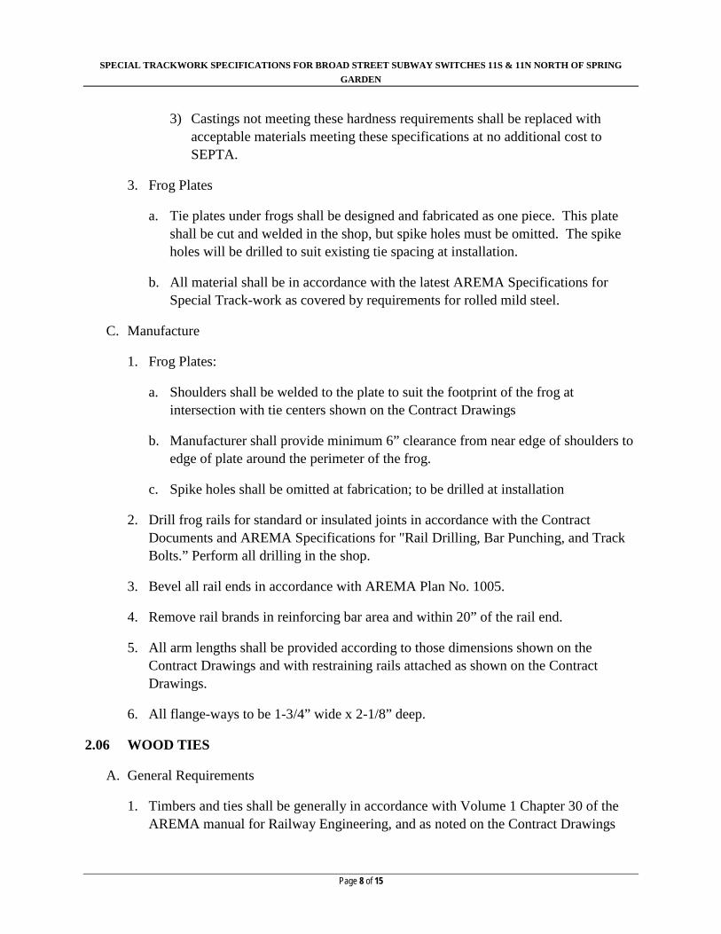
3. Frog Plates
a. Tie plates under frogs shall be designed and fabricated as one piece. This plate shall be cut and welded in the shop, but spike holes must be omitted. The spike holes will be drilled to suit existing tie spacing at installation.
b. All material shall be in accordance with the latest AREMA Specifications for Special Track-work as covered by requirements for rolled mild steel.
C. Manufacture
1. Frog Plates:
a. Shoulders shall be welded to the plate to suit the footprint of the frog at intersection with tie centers shown on the Contract Drawings
b. Manufacturer shall provide minimum 6” clearance from near edge of shoulders to edge of plate around the perimeter of the frog.
c. Spike holes shall be omitted at fabrication; to be drilled at installation
2. Drill frog rails for standard or insulated joints in accordance with the Contract Documents and AREMA Specifications for "Rail Drilling, Bar Punching, and Track Bolts.” Perform all drilling in the shop.
3. Bevel all rail ends in accordance with AREMA Plan No. 1005.
4. Remove rail brands in reinforcing bar area and within 20” of the rail end.
5. All arm lengths shall be provided according to those dimensions shown on the Contract Drawings and with restraining rails attached as shown on the Contract Drawings.
6. All flange-ways to be 1-3/4” wide x 2-1/8” deep.
2.06 WOOD TIES
A. General Requirements
1. Timbers and ties shall be generally in accordance with Volume 1 Chapter 30 of the AREMA manual for Railway Engineering, and as noted on the Contract Drawings

SPECIAL TRACKWORK SPECIFICATIONS FOR BROAD STREET SUBWAY SWITCHES 11S & 11N NORTH OF SPRING GARDEN
Page 9 of 15
and in these specifications.
B. Materials
1. The following are approved types of hardwood ties; the Manufacturer may provide any one type or a combination thereof:
a. Red Oak
b. White Oak
c. Hard Maples
d. Birches
e. Cherries
f. Hickories
g. White Walnut
C. Manufacture
1. All ties shall be 5-1/2” deep X 10” wide and of the lengths noted on the Contract Drawings
2. All ties shall be tagged with their respective tie number and switch end: e.g. “## BSS 11N Spring Garden”
3. All ties shall be gang nailed at ends
4. Ties shall be delivered un-plated and free of any spike holes, other drillings, and defects
2.07 RAIL JOINTS AND OTHER TRACK MATERIALS
D. Standard Joint Bars
1. All standard joint bars shall be manufactured according to AREMA Manual for Railway Engineering Chapter 4, Section 3.4, Specifications for Quenched Carbon-Steel Joint Bars.
E. Insulated Joints:
SPECIAL TRACKWORK SPECIFICATIONS FOR BROAD STREET SUBWAY SWITCHES 11S & 11N NORTH OF SPRING GARDEN
Page 10 of 15
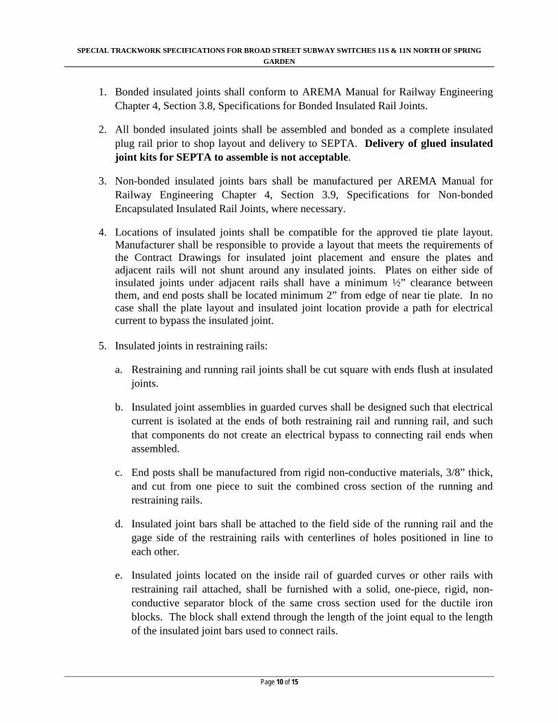
1. Bonded insulated joints shall conform to AREMA Manual for Railway Engineering Chapter 4, Section 3.8, Specifications for Bonded Insulated Rail Joints.
2. All bonded insulated joints shall be assembled and bonded as a complete insulated plug rail prior to shop layout and delivery to SEPTA. Delivery of glued insulated joint kits for SEPTA to assemble is not acceptable.
3. Non-bonded insulated joints bars shall be manufactured per AREMA Manual for Railway Engineering Chapter 4, Section 3.9, Specifications for Non-bonded Encapsulated Insulated Rail Joints, where necessary.
4. Locations of insulated joints shall be compatible for the approved tie plate layout. Manufacturer shall be responsible to provide a layout that meets the requirements of the Contract Drawings for insulated joint placement and ensure the plates and adjacent rails will not shunt around any insulated joints. Plates on either side of insulated joints under adjacent rails shall have a minimum ½” clearance between them, and end posts shall be located minimum 2” from edge of near tie plate. In no case shall the plate layout and insulated joint location provide a path for electrical current to bypass the insulated joint.
5. Insulated joints in restraining rails:
a. Restraining and running rail joints shall be cut square with ends flush at insulated joints.
b. Insulated joint assemblies in guarded curves shall be designed such that electrical current is isolated at the ends of both restraining rail and running rail, and such that components do not create an electrical bypass to connecting rail ends when assembled.
c. End posts shall be manufactured from rigid non-conductive materials, 3/8” thick, and cut from one piece to suit the combined cross section of the running and restraining rails.
d. Insulated joint bars shall be attached to the field side of the running rail and the gage side of the restraining rails with centerlines of holes positioned in line to each other.
e. Insulated joints located on the inside rail of guarded curves or other rails with restraining rail attached, shall be furnished with a solid, one-piece, rigid, non-conductive separator block of the same cross section used for the ductile iron blocks. The block shall extend through the length of the joint equal to the length of the insulated joint bars used to connect rails.

SPECIAL TRACKWORK SPECIFICATIONS FOR BROAD STREET SUBWAY SWITCHES 11S & 11N NORTH OF SPRING GARDEN
Page 11 of 15
f. Bolts shall be of sufficient length to connect bars through both running and restraining rails.
F. Track bolts, nuts, and washers for rail joints:
1. All track bolts, nuts, and washers shall be manufactured per AREMA Manual for Railway Engineering Chapter 4, Sections 3.5 and 3.6, Specifications for Heat-Treated Carbon-Steel Track Bolts and Carbon Steel Nuts, and Specifications for Spring Washers.
G. Separator block assemblies:
1. Separator blocks shall be one piece ductile iron, A536, Grade 65-45-12, and manufactured to the details provided in the Contract Drawings.
2. Head locks and flat washers for separator block assemblies shall be ductile iron, ASTM A536, Grade 65-45-12.
3. Bolts- 1-1/4” diameter x 8” square head bolt, grade 8
4. Heavy square nut and 3/8” square edge spring washer
5. Space separator blocks at 2’-0” center to center through restraining rails
H. Rail fasteners:
1. Tie plates:
a. All tie plates shall be Pandrol design with 1” diameter round holes for 15/16” diameter screw spike.
1) Spike holes greater than 1” diameter may require use of larger diameter screw spikes; Manufacturer shall provide the appropriate diameter screw spikes such that spike diameter is 1/16” less than the hole diameter at no additional cost to SEPTA.
b. Tie plates shall be canted 40h:1v towards center of track
c. Tie plates may be rolled or cast steel
1) Rolled tie plates shall meet the requirements of ASTM A-67, “Standard Specifications for Low Carbon Steel Tie Plates”. The provisions of Section S1, supplementary requirements do not apply.
SPECIAL TRACKWORK SPECIFICATIONS FOR BROAD STREET SUBWAY SWITCHES 11S & 11N NORTH OF SPRING GARDEN
Page 12 of 15
2) If Cast tie plates are to be used the Manufacturer must submit for SEPTA approval the grade of steel to be used.
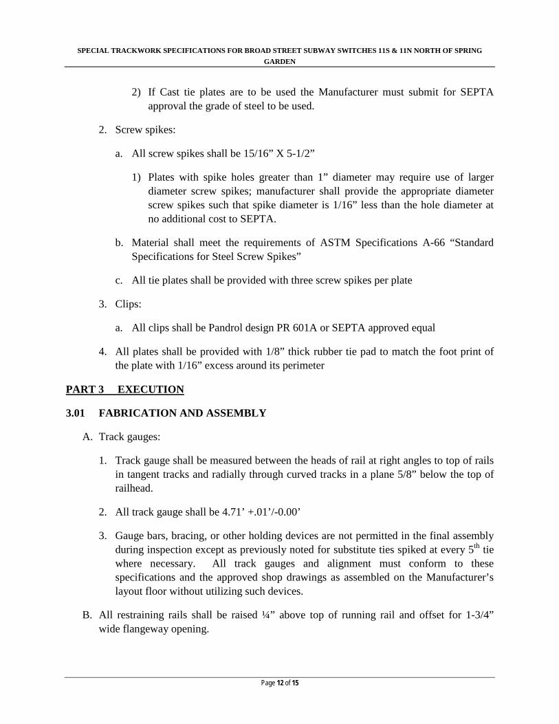
2. Screw spikes:
a. All screw spikes shall be 15/16” X 5-1/2”
1) Plates with spike holes greater than 1” diameter may require use of larger diameter screw spikes; manufacturer shall provide the appropriate diameter screw spikes such that spike diameter is 1/16” less than the hole diameter at no additional cost to SEPTA.
b. Material shall meet the requirements of ASTM Specifications A-66 “Standard Specifications for Steel Screw Spikes”
c. All tie plates shall be provided with three screw spikes per plate
3. Clips:
a. All clips shall be Pandrol design PR 601A or SEPTA approved equal
4. All plates shall be provided with 1/8” thick rubber tie pad to match the foot print of the plate with 1/16” excess around its perimeter
PART 3 EXECUTION
3.01 FABRICATION AND ASSEMBLY
A. Track gauges:
1. Track gauge shall be measured between the heads of rail at right angles to top of rails in tangent tracks and radially through curved tracks in a plane 5/8” below the top of railhead.
2. All track gauge shall be 4.71’ +.01’/-0.00’
3. Gauge bars, bracing, or other holding devices are not permitted in the final assembly during inspection except as previously noted for substitute ties spiked at every 5th tie where necessary. All track gauges and alignment must conform to these specifications and the approved shop drawings as assembled on the Manufacturer’s layout floor without utilizing such devices.
B. All restraining rails shall be raised ¼” above top of running rail and offset for 1-3/4” wide flangeway opening.

SPECIAL TRACKWORK SPECIFICATIONS FOR BROAD STREET SUBWAY SWITCHES 11S & 11N NORTH OF SPRING GARDEN
Page 13 of 15
C. Rail bending:
1. All curved rails shall be bent true to template throughout their entire length and depth so that they may rest in a horizontal plane. Crop rail ends as necessary to achieve bending throughout the entire length of rail.
2. Bend joint bars as necessary to suit connecting rail sections.
D. Rail cutting and grinding:
1. Rail ends shall be cut square to the axis of the rail; a variation of not more than 1/32" in will be permitted.
2. All rails shall be cut using abrasive saw; torch cutting is not permitted in any case.
3. Bevel all rail ends in accordance with AREMA Plan No. 1005.
4. Rails shall be cut to specified lengths on approved shop drawings with variation not to exceed 1/16” at rail temperature of 70 degrees Fahrenheit.
5. Gaps between adjoining rail sections shall be 1/8” at rail temperature of 70 degrees Fahrenheit with a variation of +1/32”/-0”.
6. Grind rail branding flush to web of rail as required to properly install joint bars and separator blocks.
3.02 MARKINGS
A. All switches, frogs, and rails of the complete special trackwork layout shall be painted or stenciled before shipment with identifications as shown on approved shop drawings, frog and rail schedules, and bill of materials.
B. The ends of each abutting section at a joint shall be legibly marked on the tread surface with the letter or number of the corresponding joint shown on the approved shop drawings. Corresponding joint bars shall also be marked with this letter or number.
C. All markings must be white on solid black background with letters and numbers as large as practical.
3.03 INSPECTIONS
A. The Vendor shall provide for outside inspection services to inspect the complete layout assembled in whole on the Manufacturers’ layout floor. The Vendor shall provide the Inspector with copies of these specifications and all approved shop drawings in sufficient time before the inspection for their review.

SPECIAL TRACKWORK SPECIFICATIONS FOR BROAD STREET SUBWAY SWITCHES 11S & 11N NORTH OF SPRING GARDEN
Page 14 of 15
B. Preapproved Inspection Agencies:
1. Trackwork Design Incorporated, 16 East Derry Road, Hershey, Pennsylvania 17033.
a. The preapproved inspection agency listed herein is not required. The Vendor may submit to SEPTA for approval alternate agencies to perform the inspection. The inspection agency chosen must be experienced in special trackwork design and construction, and provide a list of credentials including the number of years performing similar work.
C. The inspection shall verify that all dimensions, materials, and assemblies conform to the approved shop drawings and these specifications. Particular attention shall be given to:
1. Track gauges
2. Rail lengths and joint gaps
3. Locations of insulated joints
4. Proper seating in rail plates
5. Lead lengths and track centers
6. Frog arm lengths and spreads
7. Markings
8. Visual inspection for any kinks or other noticeable horizontal anomalies.
D. The Inspector shall submit to SEPTA a detailed inspection report highlighting any defects and nonconforming features. The report shall include copies of approved shop drawings marked with all dimensions as measured during the inspection. The inspector shall record the date, ambient and rail surface temperatures on the shop drawings at the time of inspection.
E. The Inspector shall take color photographs at the time of inspection and submit all photos with descriptions to SEPTA attached with their report. The photographs must include the following:
1. All assembled switch sets, frogs, and crossing diamonds.
2. Views from each switch end through the entire layout.
3. Overhead views (if possible).
4. Photos of any defects or nonconformance items as needed.

SPECIAL TRACKWORK SPECIFICATIONS FOR BROAD STREET SUBWAY SWITCHES 11S & 11N NORTH OF SPRING GARDEN
Page 15 of 15
3.04 PACKAGING AND DELIVERY
A. Delivery of all materials shall be made in the time frame and to the location specified in Schedule ‘A’ of the Bid Documents.
B. The Vendor must notify SEPTA three working days in advance of any deliveries and submit a packing list for review at that time.
C. Materials damaged during shipment and/or determined as defective once received shall be replaced at no additional cost to SEPTA.
D. All small parts shall be crated and/or palletized with contents clearly marked on the outside of containing vessels.
END OF SPECIFICATION

GENERAL NOTES
ORDINARY JOINT
ORDINARY JOINT IN RESTRAINING RAIL
PROPOSED WORK
3RD RAIL
100#RB H.H.
BASE
100#RB SHEARED
PROPOSED INSULATED JOINT (IJ)
EXISTING ORDINARY JOINT (EJ)
EXISTING INSULATED JOINT (EIJ)
IN RESTRAINING RAIL
EXISTING ORDINARY JOINT
EXISTING TO REMAIN
LEGEND
3RD RAIL END APPROACH
PF
TH
EO.
EXISTING WELD
MA
TC
H
LIN
EM
AT
CH
LIN
E
PROPOSED WORK ON SHEET 2
MA
TC
H
LIN
E
DW
G 5-
W-
63723
DW
G 5-
W-
63723
DW
G 5-
W-
63723
CONCRETE CONDUIT
GLUED IJ
GLUED IJGLUED IJ
SPRING GARDEN FAIRMOUNT
04°11'22"
13.00'13.00'
17.01'16.00'
LINE SIDE
IJ MOVED 13.97' NORTH OF EXISTING
IJ MOVED 16.89' NORTH OF EXISTING
BLANK AND DRILLED IN THE FIELD
8) RAIL LENGTHS MARKED C.T.S. (CUT TO SUIT) ARE TO BE LEFT
BEYOND ENDS OF EXISTING RAIL
CUT TO SUIT (C.T.S.) LENGTHS SHOWN PROVIDE APPROX. 1'
EXISTING JOINT (EJ) LOCATIONS SHOWN ARE APPROXIMATE.7)
JOINTS
ALLOW 0.01' FOR ORDINARY JOINTS, 0.03' FOR INSULATED6)
ALL RAIL LENGTHS PROVIDED MEASURED ALONG GAGE LINES5)
CURVE RADII GIVEN TO GAGE OF INSIDE RAIL4)
TRACK GAUGE=4.71'3)
ALL RAIL SHALL BE 100-8 OR 100# RB HEAD HARDENED2)
DETAIL 5100
22'STRAIGHT POINTS WITH GRADUATED RISERS USING POINT
ALL PROPOSED SWITCH POINTS SHALL BE STANDARD AREMA1)
1 39.00'
4 39.00'
41 16.00'
01°21'23"22' STR. PTS.
1510.68'
1510.68'
EJ
EJ
EJ
3 25.00'
8 19.50'
6 14.00'
POI
NT
OF
SWI
TC
H
42 19.50'
2 39.00' C.T.S.
(38.88' HOT)
10 38.50' C.T.S.
(37.25' HOT)
7.24'
14.26'
14.26'
7.24'
POINT OF FROG)2
1
106.06' ACTUAL LEAD (TO 105.49' THEO LEAD
(OUT) 76.40'(IN) 76.14'2°53'15"
0.75'
0.75'
39 9.00' 40 9.00'
13 9.52'
15 19.50'
EJ
CUT IN
13.92'
12.25'
11.16'
5 27.73'7 11.27'
9 38.50' C.T.S. (37.40' HOT)
12 13.17'
18 17.00' C.T.S.
(15.95' HOT)
16 19.50' C.T.S. (18.46' HOT)
17 11.50' C.T.S.
(10.65' HOT)
14 21.00' C.T.S. (20.00' HOT)
11 31.41'
S:\
Tra
ck_Civil_Engin
eering\L
ocations\C
TD\B
SS\S
PRIN
G G
AR
DE
N N\1
1S\Pla
ns\C
AD
D\S
HE
ET
S\S
PRIN
GG
AR
DE
N_T-0
1.d
gn
pdf-jps.pltcfg
JPS-W
OR
KIN
G.tbl
SHEET NUMBER
DWG. NO.:
OF
OF
SHT. NO.:
REV. NO.:
SOUTHEASTERN
PENNSYLVANIA
TRANSPORTATION
AUTHORITY
CK'D
DA
TE
RE
VD
ES
CRIP
TIO
NB
YA
P'D
SCALE:
DRAWN BY:DATE:
WORK ORDER NO.:
SCALE FACTOR:
CHECKED BY:
ARCHIVE NO.:
1234 MARKET ST, 13TH FL,
PHILADELPHIA, PA 19107
COMPUTER FILE NO.:
OPERATIONS ENGINEERING
CT
D
TR
AC
K
AS NOTED 1:1
COMPUTER FILE NO NO.
--
--
--
--
--
--
--
--
--
--
--
--
--
--
--
--
--
--
--
--
--
CHIEF ENGINEER - EM&C
CHIEF ENGINEERING OFFICER - B&B
CHIEF RAIL TRANSIT OFFICER
SYSTEM SAFETY
PROJECT MANAGER
DIRECTOR OF ENGINEERING - TRACK
MANAGER - TRACK / ENGINEERING
DMK
KAS
BR
OA
D S
TR
EE
T S
UB
WA
Y
TU
RN
OU
T 1
1-S
NO
RT
H O
F S
PRIN
G G
AR
DE
N S
TA
TIO
N
LA
YO
UT A
ND G
EO
METR
Y P
LA
N
1 2
1 1
860-1067
5-W-63722
5.10.2016
26.24'
-1.70'
0.33'
2.17'
4.00'
5.54'
7.21'
8.88'
10.54'
12.25'
14.00'
15.75'
17.50'
19.33'
21.17'
22.83'
24.23'P
OIN
T
OF
SWIT
CH
PARALLEL TO STRAIGHT TRACKBASELINE DIMENSIONS TO PS MEASURED
#0: 10'-0"
X10"
X5•
"
#1: 11'-0"
X8"
X5•
"
#2: 10'-0"
X8"
X5•
"
#3: 8'-0"
X8"
X5•
"
#4: 9'-6"
X10"
X5•
"
#5: 8'-0"
X10"
X5•
"
#6: 8'-0"
X10"
X5•
"
#7: 8'-0"
X10"
X5•
"
#8: 9'-6"
X10"
X 5•
"
#9: 8'-0"
X10"
X5•
"
#10: 8'-0"
X10"
X5•
"
#11: 8'-0"
X10"
X5•
"
#12: 9'-6"
X10"
X5•
"
#13: 8'-0"
X10"
X5•
"
#14: 8'-0"
X10"
X5•
"
#15: 8'-0"
X10"
X5•
"
#16: 9'-0"
X10"
X5•
"
#17: 11'-6"
X10"
X5•
"
#18: 8'-0"
X10"
X5•
"
#19: 8'-0"
X10"
X5•
"
#20: 12'-0"
X10"
X5•
"
#21: 8'-6"
X10"
X5•
"
#22: 8'-6"
X10"
X5•
"
#23: 9'-6"
X10"
X5•
"
#24: 12'-0"
X10"
X5•
"
#25: 9'-6"
X10"
X5•
"
#26: 9'-6"
X10"
X5•
"
#27: 9'-6"
X10"
X5•
"
#28: 12'-6"
X10"
X5•
"
#29: 9'-6"
X10"
X5•
"
#30: 9'-6"
X10"
X5•
"
#31: 9'-6"
X10"
X5•
"
#32: 13'-0"
X10"
X5•
"
#33: 9'-6"
X10"
X5•
"
#34: 9'-6"
X10"
X5•
"
#35: 13'-0"
X10"
X5•
"
#36: 10'-0"
X10"
X5•
"
#37: 10'-0"
X10"
X5•
"
#38: 10'-0"
X10"
X5•
"
#39: 10'-0"
X10"
X5•
"
#40: 13'-6"
X10"
X5•
"
#41: 10'-0"
X10"
X5•
"
#42: 10'-4"
X10"
X5•
"
#43: 10'-4"
X10"
X5•
"
#44: 14'-0"
X10"5•
"
#45: 7'-8"
X10"
X5•
"
#46: 7'-8"
X10"
X5•
"
#47: 8'-0"
X10"
X5•
"
#48: 8'-0"
X10"
X5•
"
#49: 9'-6"
X10"
X5•
"
#50: 8'-0"
X10"
X5•
"
#51: 8'-0"
X10"
X5•
"
#52: 8'-0"
X10"
X5•
"
#53: 9'-6"
X10"
X5•
"
#54: 8'-0"
X10"
X5•
"
#55: 8'-0"
X10"
X5•
"
#56: 8'-0"
X10"
X5•
"
#57: 9'-6"
X10"
X5•
"
#58: 8'-0"
X10"
X5•
"
#59: 8'-0"
X10"
X5•
"
#60: 8'-0"
X10"
X5•
"
#61: 10'-0"
X10"
X5•
"
#6
2:
9'-
6"
X1
0"
X5•
"
#6
3:
9'-
6"
X1
0"
X5•
"
#64: 9'-6"
X10"
X5•
"
#65: 10'-6"
X10"
X5•
"
#66: 9'-6"
X10"
X5•
"
#6
7:
9'-
6"
X1
0"
X5•
"
#68: 9'-6"
X10"
X5•
"
#6
9:
11'-
0"
X1
0"
X5•
"
#7
0:
9'-
6"
X1
0"
X5•
"
#7
1:
9'-
6"
X1
0"
X5•
"
#7
2:
9'-
6"
X1
0"
X5•
"
#73: 11'-0"
X10"
X5•
"
#7
4: 9'-6"
X10"
X5•
"
#7
5:
9'-
6"
X1
0"
X5•
"
#76: 10'-0"
X10"
X5•
"
#77: 12'-0"
X10"
X5•
"
#78: 10'-0"
X10"
X5•
"
#79: 5'-4"
X10"
X5•
"
#80: 5'-4"
X10"
X5•
"
#8
1:
5'-
0"
X1
0"
X5•
"
#82: 5'-0"
X10"
X5•
"
#83: 4'-8"
X10"
X5•
"
#84: 4'-8"
X10"
X5•
"
#85: 4'-8"
X10"
X5•
"
#86: 4'-4"
X10"
X5•
"
#87: 4'-4"
X10"
X5•
"
#88: 4'-0"
X10"
X5•
"
#89: 4'-0"
X10"
X5•
"
#90: 9'-6"
X10"
X5•
"
#9
1: 9'-6"
X10"
X5•
"
#92: 11'-0"
X10"
X5•
"

PF
TH
EO.
(01°21'23")
22' STR. PTS.
SPRING GARDEN FAIRMOUNT
'0.75
MA
TC
H
LIN
EM
AT
CH
LIN
E
CUT IN
BOLTED IJBOLTED IJ
PROPOSED IJ LOCATION IS 14.69' SOUTH OF EXISTING
PROPOSED IJ LOCATION IS 16.95' SOUTH OF EXISTING
MA
TC
H
LIN
E
GLUED IJ
GLUED IJ
DW
G 5-
W-63722
DW
G 5-
W-63722
DW
G 5-
W-63722
GENERAL NOTES
ORDINARY JOINT
ORDINARY JOINT IN RESTRAINING RAIL
PROPOSED WORK
3RD RAIL
100#RB H.H.
BASE
100#RB SHEARED
PROPOSED INSULATED JOINT (IJ)
EXISTING ORDINARY JOINT (EJ)
LEGEND
EXISTING INSULATED JOINT (EIJ)
IN RESTRAINING RAIL
EXISTING ORDINARY JOINT
EXISTING TO REMAIN
3RD RAIL END APPROACH
EXISTING WELD
PROPOSED WORK ON SHEET 2
11.53'
12.25'
13.92'
4°11'22"
1.92'
CONCRETE CONDUIT
13.00'13.00'
LINE SIDE
BLANK AND DRILLED IN THE FIELD
8) RAIL LENGTHS MARKED C.T.S. (CUT TO SUIT) ARE TO BE LEFT
BEYOND ENDS OF EXISTING RAIL
CUT TO SUIT (C.T.S.) LENGTHS SHOWN PROVIDE APPROX. 1'
EXISTING JOINT (EJ) LOCATIONS SHOWN ARE APPROXIMATE.7)
JOINTS
ALLOW 0.01' FOR ORDINARY JOINTS, 0.03' FOR INSULATED6)
ALL RAIL LENGTHS PROVIDED MEASURED ALONG GAGE LINES5)
CURVE RADII GIVEN TO GAGE OF INSIDE RAIL4)
TRACK GAUGE=4.71'3)
ALL RAIL SHALL BE 100-8 OR 100# RB HEAD HARDENED2)
DETAIL 5100
22'STRAIGHT POINTS WITH GRADUATED RISERS USING POINT
ALL PROPOSED SWITCH POINTS SHALL BE STANDARD AREMA1)
43 16.00'
44 16.00'
25 24.94'
22 39.00'
26 23.05'32 19.50'
34 39.00' 36 23.82' 38 21.50'
31 19.50'
21 31.77'
20 27.15'
1510.68'
1510.68'
7.25'
7.25'
14.25'
14.25'
45 9.00'
46 9.00'
POI
NT
OF
SWI
TC
H
29 9.16'
37 19.50'35 25.49'33 39.00'27 39.00'23 19.50'19 32.79'
30 19.50'28 10.20'
24 19.50'
(15.95' HOT)
18 17.00' C.T.S.
15 19.50'
(OUT) 76.36'(IN) 75.95'02°52'50"
106.03' ACTUAL LEAD (TO 1/2 POINT OF FROG)
105.46' THEO. LEAD
S:\
Tra
ck_Civil_Engin
eering\L
ocations\C
TD\B
SS\S
PRIN
G G
AR
DE
N N\1
1N\Pla
ns\C
AD
D\S
HE
ET
S\S
PRIN
GG
AR
DE
N_11
N.d
gn
pdf-jps.pltcfg
JPS-W
OR
KIN
G.tbl
SHEET NUMBER
DWG. NO.:
OF
OF
SHT. NO.:
REV. NO.:
SOUTHEASTERN
PENNSYLVANIA
TRANSPORTATION
AUTHORITY
CK'D
DA
TE
RE
VD
ES
CRIP
TIO
NB
YA
P'D
SCALE:
DRAWN BY:DATE:
WORK ORDER NO.:
SCALE FACTOR:
CHECKED BY:
ARCHIVE NO.:
1234 MARKET ST, 13TH FL,
PHILADELPHIA, PA 19107
COMPUTER FILE NO.:
OPERATIONS ENGINEERING
CT
D
TR
AC
K
AS NOTED 1:1
COMPUTER FILE NO NO.
--
--
--
--
--
--
--
--
--
--
--
--
--
--
--
--
--
--
--
--
--
CHIEF ENGINEER - EM&C
CHIEF ENGINEERING OFFICER - B&B
CHIEF RAIL TRANSIT OFFICER
SYSTEM SAFETY
PROJECT MANAGER
DIRECTOR OF ENGINEERING - TRACK
MANAGER - TRACK / ENGINEERING
DMK
KAS
BR
OA
D S
TR
EE
T S
UB
WA
Y
TU
RN
OU
T 1
1-N
NO
RT
H O
F S
PRIN
G G
AR
DE
N S
TA
TIO
N
LA
YO
UT A
ND G
EO
METR
Y P
LA
N
2 2
1 1
860-1067
5-W-63723
5.10.2016
PARALLEL TO STRAIGHT TRACKBASELINE DIMENSIONS TO PS MEASURED
0.
33'
5.54'
7.21'
8.
88'
10.54'
12.
25'
19.33'
21.
17'
22.83'
24.
23'
POIN
T
OF
SWIT
CH
PARALLEL TO STRAIGHT TRACKBASELINE DIMENSIONS TO PS MEASURED
4.
00'
2.
17'
-1.70'
13.72'
15.
69'
17.64'
#92: 11'-0"
X10"
X5•
"
#93: 9'-6"
X10"
X5•
"
#94: 9'-6"
X10"
X5•
"
#95: 9'-6"
X10"
X5•
"
#96: 11'-0"
X10"
X5•
"
#97: 9'-5"
X10"
X5•
"
#98: 9'-5"
X10"
X5•
"
#99: 9'-5"
X10"
X5•
"
#100: 10'-10"
X10"
X5•
"
#101: 9'-4"
X10"
X5•
"
#102: 9'-4"
X10"
X5•
"
#103: 9'-4"
X10"
X5•
"
#104: 11'-0"
X10"
X5•
"
#105: 7'-2.5"
X10"
X5•
"
#106: 7'-2.5"
X10"
X5•
"
#107: 7'-2.5"
X10"
X5•
"
#108: 9'-0"
X10"
X5•
"
#1
09: 7'-2.5"
X10"
X5•
"
#1
10: 7'-2.5"
X10"
X5•
"
#1
11: 7'-2.5"
X10"
X5•
"
#1
12: 9'-0"
X10"
X5•
"
#113: 7'-2.5"
X10"
X5•
"
#1
14: 10'-0"
X10"
X5•
"
#1
15: 12'-0"
X10"
X5•
"
#116: 11'-8"
X10"
X5•
"
#117: 10'-0"
X10"
X5•
"
#1
18: 11'-8"
X10"
X5•
"
#119: 9'-8"
X10"
X5•
"
#1
20: 11'-4"
X10"
X5•
"
#1
21: 11'-4"
X10"
X5•
"
#1
22: 9'-4"
X10"
X5•
"
#1
23: 9'-4"
X10"
X5•
"
#1
24: 11'-0"
X10"
X5•
"
#125: 11'-0"
X10"
X5•
"
#126: 9'-0"
X10"
X5•
"
#127: 9'-0"
X10"
X5•
"
#12
8: 10'-8"
X10"
X5•
"
#1
29: 10'-8"
X10"
X5•
"
#13
0: 8'-8"
X9.5"
X5•
"
#131: 8'-8"
X10"
X5•
"
#132: 10'-4"
X10"
X5•
"
#13
3: 10'-4"
X10"
X5•
"
#13
4: 8'-4"
X10"
X5•
"
#13
5: 8'-4"
X10"
X5•
"
#1
36: 10'-0"
X10"
X5•
"
#1
37: 10'-0"
X10"
X5•
"
#1
38:
8'-
0"
X1
0"
X5•
"
#13
9: 8'-0"
X10"
X5•
"
#14
0: 9'-5"
X10"
X5•
"
#141: 9'-8"
X10"
X5•
"
#142: 7'-8"
X10"
X5•
"
#1
43:
8'-
0"
X1
0"
X5•
"
#14
4: 8'-0"
X10"
X5•
"
#145: 9'-6"
X10"
X5•
"
#14
6: 8'-0"
X10"
X5•
"
#14
7: 8'-0"
X10"
X5•
"
#1
48:
8'-
0"
X9.
5"
X5•
"
#1
49: 9'-6"
X10"
X5•
"
#1
50:
8'-
0"
X1
0"
X5•
"
#15
1: 8'-0"
X10"
X5•
"
#1
52:
8'-
0"
X1
0"
X5•
"
#153: 9'-6"
X10"
X5•
"
#154: 8'-0"
X10"
X5•
"
#15
5: 8'-0"
X8"
X5•
"
#15
6: 10'-0"
X8"
X5•
"
#157: 11'-0"
X8"
X5•
"
#158: 10'-0"
X9.5"
X5•
"

SOUTHEASTERN PENNSYLVANIA TRANSPORTATION AUTHORITY
SPECIFICATIONS FOR THE PROCUREMENT OF TRACKWORK MATERIALS:
Broad Street Subway – North of AT&T Station
Jul 21, 2016

TRACKWORK MATERIAL SPECIFICATIONS FOR NUMBER 11 DOUBLE CROSSOVER DIAMOND
7/21/16 Page 1 of 13
PART 1 GENERAL
1.01 SUMMARY
A. This specification is intended to cover the requirements of the Southeastern Pennsylvania Transportation Authority, (SEPTA), for the manufacture of track work to be installed on the Broad Street Subway (BSS) North of AT&T Station.
B. This work includes all labor, material, equipment and tools necessary in order to design, manufacture, furnish, shop assemble, mark, inspect, disassemble, package, and deliver all track work materials including wood cross ties, for a complete layout of the following:
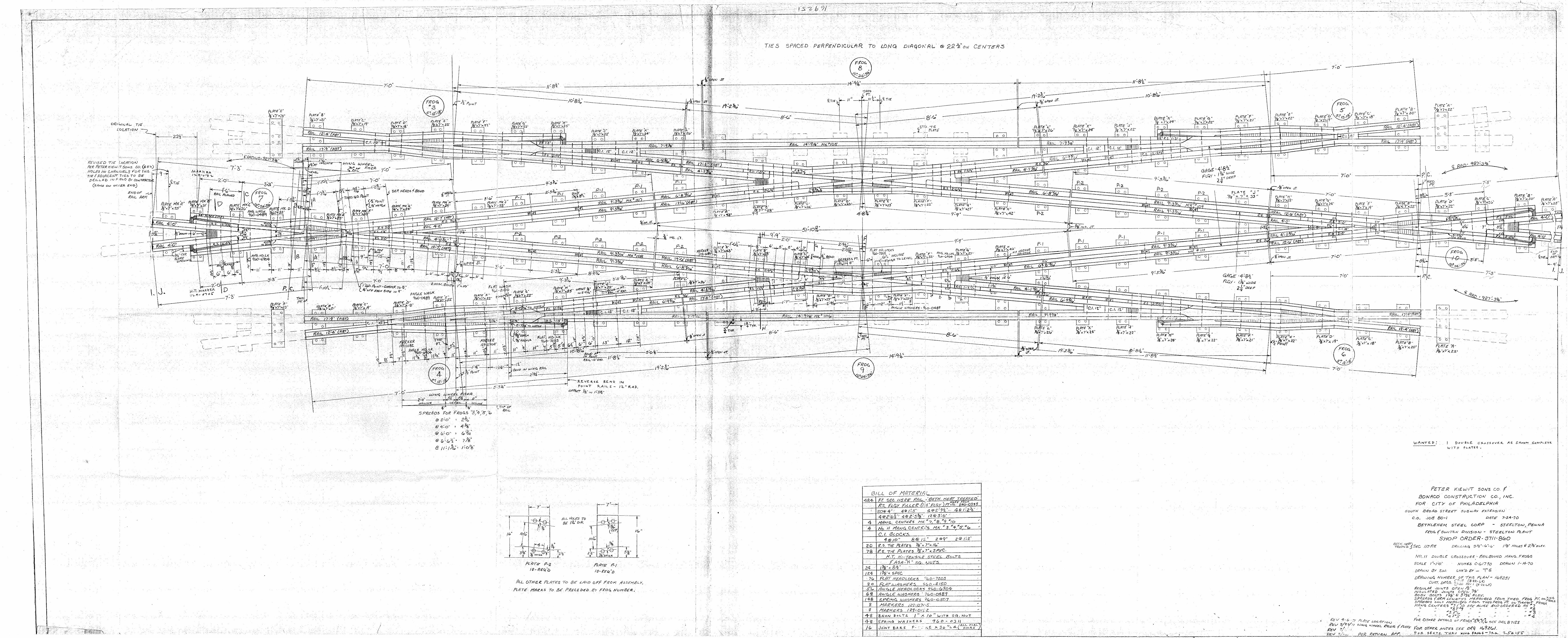
1. One (1) 115#RE number 11 double crossover diamond.
C. Prior to manufacturing, the Vendor must provide detailed shop drawings including a bill of materials for SEPTA approval.
D. After shop assembly, an outside inspection agency shall be hired by the Vendor, at no
additional cost to SEPTA to inspect all parts and the layout assembled in its entirety for fit, quality, and conformance to these specifications. The inspection agency must submit detailed inspection reports including color photographs, to SEPTA for approval prior to shipping. The inspection agency will also be responsible for production update reports to SEPTA. Any parts or dimensions not meeting the parameters of this specification or in the judgment of the inspector determined as defective shall be replaced and/or corrected by the Manufacturer at no additional cost to SEPTA.
E. Deliveries of all materials shall be within the time frame specified in these Contract Documents. Within seven days of award the Vendor must submit a detailed delivery schedule to SEPTA for approval. The schedule outline must include all dates and durations for: design, shop drawing submittals, manufacturing, assembly, inspections, and deliveries.
1.02 DRAWINGS
A. Contract Drawings are as follows. Standard drawings shall only be used for guidance in the development of manufacturers shop drawings. The drawings provided shall not be considered the final approved set and shall not be substituted for shop drawing submissions. Final shop drawings shall be tailored to suit the specific track geometry of each layout.
1. No. 11 Double Crossover Railbound Mang. Frogs, Drawing Number-169251

TRACKWORK MATERIAL SPECIFICATIONS FOR NUMBER 11 DOUBLE CROSSOVER DIAMOND
7/21/16 Page 2 of 13
1.03 REFERENCE STANDARDS
A. A.R.E.M.A., Latest edition, “Portfolio of Track-work Plans” and “Manual For Railway Engineering”
B. American Society for Testing and Materials (ASTM), Standard Specifications:
1. A536, Ductile Iron Castings
2. A-66, Standard Specifications for Steel Screw Spikes
3. ASTM A-67, Standard Specifications for Low Carbon Steel Tie Plates
1.04 SUBMITTALS
A. All shop drawing transmittals shall be made using black and white paper prints, and electronic copies in Portable Document Format, PDF. All Computer Aided Drafting and Design, CADD, files used in creating final shop drawings shall be released to SEPTA at the completion of the project for final record keeping. All CADD files must be compatible with Microstation V8 or AutoCADD Version 2010.
B. The Vendor shall submit the following to SEPTA for approval before fabrication:
1. Shop Drawings:
a. All shop drawing dimension units shall be in feet and inches given to an accuracy of one sixteenth of an inch. Fractions of an inch less than one-sixteenth may be used where greater accuracy is required in fabrication.
b. Scaled shop drawings shall be provided for the following:
1) Railbound manganese frogs.
2) Rail schedule including bending, and drilling sketches. Sketches must show rail and joint identifications, as marked during shop layout and matching those shown on the complete layout.
3) Tie plate locations.
4) One complete layout, showing the track geometric data, and identifying all: rail lengths, frogs, rail joints, and plates. Lettering and numbering schemes must be used to identify joints, rails, and frogs. A rail schedule and a complete bill of materials must also be provided on the complete layout.
2. Manufacturers catalog cuts and data as necessary.
TRACKWORK MATERIAL SPECIFICATIONS FOR NUMBER 11 DOUBLE CROSSOVER DIAMOND
7/21/16 Page 3 of 13
3. Inspection reports including color photographs of all frogs and complete layouts assembled in their entirety.
4. Quality management systems certificates and/or procedures.
5. Product Data: Submit the procedure to be used in the depth hardening of frog and diamond castings.
6. Certificates and Reports:
a. Certificates of material compliance required by AREMA and this Specification.
b. Test reports of chemical analyses, Brinell hardness, and other tests required by A.R.E.M.A. and the Contract Documents.
c. Frog depth hardening results.
7. Submittal comments shall be returned from SEPTA to the Vendor within eight business days.
1.05 QUALITY ASSURANCE
A. All manufacturers shall be ISO 9001 certified, or have an alternate quality management system in place.
B. Manufacturers not ISO 9001 certified must provide documentation of their quality management system in place and submit this documentation to SEPTA for approval. This documentation must detail the following procedures:
1. Vendor surveillance (All subcontractors)
2. Drawing Control (changes)
3. Document Control
4. Inspection Procedures - in process and final
5. Production Test Requirements
6. Segregation and disposition of defective material and products.
7. Material and process control in plant, identifying critical control points.
8. Production "equipment" and "instrumentation" calibration, maintenance, and data recording.

TRACKWORK MATERIAL SPECIFICATIONS FOR NUMBER 11 DOUBLE CROSSOVER DIAMOND
7/21/16 Page 4 of 13
9. Work procedures and instructions.
10. Failure reporting analysis and corrective action.
11. Sample plans and quality levels for high count items.
12. Raw material standards and controls.
13. Records of test and inspection.
14. Storage, handling and shipment controls.
15. Quality Control, QC, organization chart showing all QC personnel and their level of authority. QC organization should report independently from Production to Project Manager level or above.
C. Before any of the work of a layout is shipped, the parts shall be assembled on the Manufacturer's layout floor according to the approved shop drawings. The complete layout shall be inspected by the approved inspection agency and checked for proper fit and conformity with the approved shop drawings and this specification. As specified herein wood ties not to be pre-plated must still be laid out on the manufacturer’s floor under the steel as a complete assembly of the special trackwork layout. For layout and inspection purposes substitute ties of equal dimensions may be used in the shop layout if plate hold down is necessary to properly align rails.
PART 2 PRODUCTS
2.01 STEEL RAILS
A. Material:
1. All steel rails shall be new and in accordance with the current edition of the A.R.E.M.A. Manual for Railway Engineering, Volume 1, Chapter 4, Part 2.1, “Specifications for Steel Rails,” except as modified and supplemented as follows:
a. Rail section to be 115 lb. RE head hardened as specified in section 1.01 B.
B. Design and Manufacture:
1. The manufacturer shall provide all lead, closure and turnout rails necessary to completely assemble each turnout from the toe of stock rail through the last long timber in turnouts. Rail lengths shall be provided in accordance with the Contract Drawings or as modified in the SEPTA approved Shop Drawings.
2. Bevel rails ends according to AREMA Plan No. 1005.

TRACKWORK MATERIAL SPECIFICATIONS FOR NUMBER 11 DOUBLE CROSSOVER DIAMOND
7/21/16 Page 5 of 13
3. Drilling
a. Rail ends scheduled to be bolted shall be fully drilled, those scheduled to be field welded shall be partially drilled (back drilled), and those scheduled to be cut to fit at installation shall have one end blank, no drilling. Manufacturer to provide joint bars and bolts for all joint locations including those indicated as field welds on Contract Drawings.
b. Drill all rails in accordance with these Specifications, Contract Drawings, and A.R.E.M.A. Manual for Railway Engineering, Volume 1, Chapter 3, Section 3.3, “Rail Drilling, Bar Punching, and Track Bolts."
c. All drilling of special track-work rails shall be performed in the shop.
d. Rails scheduled for field welding shall be drilled according to standard rail end drilling except with the hole closest to the rail end omitted.
4. All curved rails shall be pre-bent in the shop.
2.02 TIE PLATES AND RAIL BRACES
A. Material:
1. All plates shall be fabricated from material meeting the latest A.R.E.M.A. specifications.
2. All castings shall meet ASTM specifications A536, Ductile Iron Castings or SEPTA approved equal.
3. All clips shall be Pandrol “e”-2055.
B. Design and Manufacture:
1. All rail braces shall be the adjustable boltless type design incorporating Pandrol ‘”e” clip rail fasteners.
2. All plates shall be cut, milled, drilled, and welded in the shop.
2.03 FROGS
A. Materials:
1. Rail used in the manufacture of frog components shall conform to sections 2.01 above.
TRACKWORK MATERIAL SPECIFICATIONS FOR NUMBER 11 DOUBLE CROSSOVER DIAMOND
7/21/16 Page 6 of 13
2. Frog Castings
a. The castings for frogs and frog inserts shall be manganese steel.
b. All frog castings shall meet the following surface hardness requirements:
1) Minimum surface Brinell hardness number, BHN, 352 for the areas within 1” of the gauge and guard lines, and minimum BHN 321 for the balance through surface of castings.
2) Three surface hardness readings shall be taken for each casting within areas 1” of gauge and guard lines and spaced at least 12” apart. In case any hardness measurement does not meet the specified requirements two additional measurements shall be made, one on either side of the original impression, about 1” distant and parallel with gauge or guard line. If both of these measurements meet the requirements, the original reading shall be discarded, and these two readings be recorded in its place.
3) Castings not meeting these hardness requirements shall be replaced with acceptable materials meeting these specifications at no additional cost to SEPTA.
B. Manufacture and Design:
1. All frogs shall be medium wall railbound manganese with depressed points in general conformance with A.R.E.M.A. standard plans except as modified on the Contract Drawings.
2. Frog arm lengths shall be as shown on Contract Drawings.
3. All frog arms shall be fully drilled and beveled in accordance with section 2.01 above.
4. Frog plates:
a. Tie plates under frogs shall be designed and fabricated as one piece. This continuous plate shall be cut and welded in the shop, but spike holes must be omitted. The spike holes will be drilled to suit existing tie spacing at installation.
b. All material shall be in accordance with the latest AREMA Specifications for Special Track-work as covered by requirements for rolled mild steel.

TRACKWORK MATERIAL SPECIFICATIONS FOR NUMBER 11 DOUBLE CROSSOVER DIAMOND
7/21/16 Page 7 of 13
2.04 RAIL JOINTS AND OTHER TRACK MATERIALS
A. Standard Joint Bars
1. All standard joint bars shall be manufactured according to AREMA Manual for Railway Engineering Chapter 4, Section 3.4, Specifications for Quenched Carbon-Steel Joint Bars.
B. Insulated Joints:
1. All insulated joints shall be provided by the Manufacturer in the locations shown on the Contract Drawings or as directed by SEPTA during the shop drawing review process.
2. All insulated joints shall be bonded and conform to AREMA Manual for Railway Engineering Chapter 4, Section 3.8, Specifications for Bonded Insulated Rail Joints.
3. All bonded insulated joints shall be assembled and bonded as a complete insulated plug rail prior to shop layout and delivery to SEPTA. Delivery of glued insulated joint kits for SEPTA to assemble is not acceptable.
4. Non-bonded insulated joints bars shall be manufactured per AREMA Manual for Railway Engineering Chapter 4, Section 3.9, Specifications for Non-bonded Encapsulated Insulated Rail Joints, where necessary.
a. Non-bonded insulated joints shall only be permitted on arms of frogs or at ends of stock rails if required.
C. Track bolts, nuts, and washers for rail joints:
1. All track bolts and nuts shall be manufactured per AREMA Manual for Railway Engineering Chapter 4, Sections 3.5 and 3.6, Specifications for Heat-Treated Carbon-Steel Track Bolts and Carbon Steel Nuts, and Specifications for Spring Washers.
D. Rail fasteners:
1. Tie plates:
a. The manufacturer shall provide all tie plates necessary to fasten each rail of the respective turnout or crossover to the timbers provided.
b. All tie plates shall be Pandrol design with 1” diameter round holes for 15/16” diameter screw spike.

TRACKWORK MATERIAL SPECIFICATIONS FOR NUMBER 11 DOUBLE CROSSOVER DIAMOND
7/21/16 Page 8 of 13
1) Spike holes greater than 1” diameter may require use of larger diameter screw spikes; Manufacturer shall provide the appropriate diameter screw spikes such that spike diameter is 1/16” less than the hole diameter at no additional cost to SEPTA.
c. Tie plates shall be canted 40h:1v towards center of track
d. Tie plates may be rolled or cast steel
1) Rolled tie plates shall meet the requirements of ASTM A-67, “Standard Specifications for Low Carbon Steel Tie Plates”. The provisions of Section S1, supplementary requirements do not apply.
2) If Cast tie plates are to be used the Manufacturer must submit for SEPTA approval the grade of steel to be used.
2. Screw spikes:
a. All screw spikes shall 15/16” diameter X 6” length.
1) Plates with spike holes greater than 1” diameter may require use of larger diameter screw spikes; manufacturer shall provide the appropriate diameter screw spikes such that spike diameter is 1/16” less than the hole diameter at no additional cost to SEPTA.
b. Material shall meet the requirements of ASTM Specifications A-66 “Standard Specifications for Steel Screw Spikes”
c. All standard tie plates shall be provided with three screw spikes per plate, two field side and one gage side, switch and frog plates shall be provided with four spikes per tie, one at each corner of the plate.
3. Clips:
a. All clips shall be Pandrol “e”-clip or SEPTA approved equal
b. Manufacturer shall provide Pandrol C-clips and insulated C-clip assemblies at all joint and insulated joint assemblies.
PART 3 EXECUTION
3.01 FABRICATION AND ASSEMBLY
A. Track gauges:
TRACKWORK MATERIAL SPECIFICATIONS FOR NUMBER 11 DOUBLE CROSSOVER DIAMOND
7/21/16 Page 9 of 13
1. Track gauge shall be measured between the heads of rail at right angles to top of rails in tangent tracks and radially through curved tracks in a plane 5/8” below the top of railhead.
2. All track gauge shall be 56-1/2” +1/8”/-0”
3. Gauge bars, bracing, or other holding devices are not permitted in the final assembly during inspection. All track gauges and alignment must conform to these specifications and the approved shop drawings as assembled on the Manufacturer’s layout floor without utilizing such devices.
B. Rail bending:
1. All curved rails shall be bent true to template throughout their entire length and depth so that they may rest in a horizontal plane. Crop rail ends as necessary to achieve bending throughout the entire length of rail.
2. Bend joint bars as necessary to suit connecting rail sections through curved tracks.
C. Rail cutting and grinding:
1. Rail ends shall be cut square to the axis of the rail; a variation of not more than 1/32" in will be permitted.
2. All rails shall be cut using abrasive saw; torch cutting is not permitted in any case.
3. Bevel all rail ends in accordance with AREMA Plan No. 1005.
4. Rails shall be cut to specified lengths on approved shop drawings with variation not to exceed 1/16” at rail temperature of 70 degrees Fahrenheit.
5. Gaps between adjoining rail sections shall be 1/8” at rail temperature of 70 degrees Fahrenheit with a variation of +1/32”/-0”.
6. Grind rail branding flush to web of rail as required to properly install joint bars.
3.02 MARKINGS
A. All frogs and rails of the complete special trackwork layouts shall be painted or stenciled before shipment with identifications as shown on approved shop drawings, frog and rail schedules, and bill of materials.
B. The ends of each abutting section at a joint shall be legibly match-marked on the tread surface with the letter or number of the corresponding joint shown on the approved shop drawings. Corresponding joint bars shall also be marked with this letter or number.
TRACKWORK MATERIAL SPECIFICATIONS FOR NUMBER 11 DOUBLE CROSSOVER DIAMOND
7/21/16 Page 10 of 13
C. All markings must be white on solid black background with letters and numbers as large as practical.
3.03 INSPECTIONS
A. The Vendor shall provide for outside inspection services to inspect the complete layout assembled in whole on the Manufacturers’ layout floor. The Vendor shall provide the Inspector with copies of these specifications and all approved shop drawings in sufficient time before the inspection for their review.
B. Preapproved Inspection Agencies:
1. Trackwork Design Incorporated, 16 East Derry Road, Hershey, Pennsylvania 17033.
a. The preapproved inspection agency listed herein is not required. The Vendor may submit to SEPTA for approval alternate agencies to perform the inspection. The inspection agency chosen must be experienced in special trackwork design and construction, and provide a list of credentials including the number of years performing similar work.
C. The inspection shall verify that all dimensions, materials, and assemblies conform to the approved shop drawings and these specifications. Particular attention shall be given to:
1. Track gauges
2. Rail lengths and joint gaps
3. Locations of insulated joints
4. Proper seating in rail plates
5. Lead lengths and track centers
6. Frog arm lengths and spreads
7. Markings
8. Visual inspection for any kinks or other noticeable horizontal anomalies.
D. The Inspector shall submit to SEPTA a detailed inspection report highlighting any defects and nonconforming features. The report shall include copies of approved shop drawings marked with all dimensions as measured during the inspection. The inspector shall

TRACKWORK MATERIAL SPECIFICATIONS FOR NUMBER 11 DOUBLE CROSSOVER DIAMOND
7/21/16 Page 11 of 13
record the date, ambient and rail surface temperatures on the shop drawings at the time of inspection.
E. The Inspector shall take color photographs at the time of inspection and submit all photos with descriptions to SEPTA attached with their report. The photographs must include the following:
1. All assembled frogs.
2. Views from each end through the entire layout.
3. Overhead views (if possible).
4. Photos of any defects or nonconformance items as needed.
3.04 PACKAGING AND DELIVERY
A. Delivery of all materials shall be made in the time frame and to the location specified in Schedule ‘A’ of the Bid Documents.
B. The Vendor must notify SEPTA three working days in advance of any deliveries and submit a copy of the packing list for review at that time.
C. Materials damaged during shipment and/or determined as defective once received shall be replaced at no additional cost to SEPTA.
D. All small parts shall be crated and/or palletized with contents clearly marked on the outside of containing vessels.
1. Boxes made from cardboard are not acceptable; all containers shall be made from material that will not deteriorate due to outdoor storage in wet weather.
E. All ties shall be bundled using steel bands and grouped by location.
END OF SPECIFICATION