Normal MR Imaging Anatomy of the Knee - Ressonar
17
Normal MR Imaging Anatomy of the Knee Saifuddin Vohra, DO, George Arnold, MD, Shashin Doshi, MD, David Marcantonio, MD* There are several keys to successfully interpreting MR imaging examinations. Initially, constructing a solid foundation consisting of a good under- standing of basic MR imaging principles and imaging protocols as well as the appearance of normal imaging anatomy is crucial. This knowl- edge can be then applied to one’s understanding of pathology commonly encountered in the area of interest. Careful attention should be focused on awareness of commonly encountered normal variants and diagnostic pitfalls to improve accu- racy and avoid misinterpretation. In this article, MR imaging of a healthy volunteer was performed on a 3-T MR imaging unit (Siemens, Munich, Germany). Normal anatomy is depicted at repre- sentative levels throughout the knee, and descrip- tions of frequently encountered anatomic variants are provided. PROTOCOLS At the authors’ institution, a combination of intermediate-weighted proton density (PD) and T2-weighted fast spin echo sequences with and without fat suppression are used to provide excel- lent anatomic detail and localize pathology. Fat suppression accentuates bone marrow and soft tissue edema on fluid-sensitive sequences, and non–fat-suppressed images increase conspicuity of bone marrow abnormalities on short echo time (TE) sequences. Furthermore, fast spin echo PD sequences employing fat saturation are accurate and sensitive for evaluation of meniscal tears and articular cartilage disruption. In general, optimal evaluation is achieved when the imaging planes are oriented perpendicular to and parallel to the long axis of the structure in question. The multiplanar capability of MR imaging allows for oblique sagittal image acquisition oriented parallel to the lateral femoral condyle, which optimizes evaluation of the anterior cruciate ligament (ACL), horns of the menisci, femorotibial joint and femoral trochlear articular cartilage, cruciate ligaments, and extensor mechanism. The coronal plane of imaging is preferred for eval- uation of the body of the menisci, and medial and lateral stabilizing structures. The axial plane is used to evaluate the patellar articular cartilage, quadriceps tendon, and medial and lateral stabi- lizing structures. The routine knee MR imaging protocol at the authors’ institution (Table 1) consists of axial intermediate PD with fat saturation, PD sagittal oblique without fat saturation, PD coronal without fat saturation, intermediate T2 coronal with fat saturation, and intermediate T2 sagittal oblique with fat saturation sequences. When indicated, intravenous gadolinium contrast may help to further characterize neoplastic, infectious, and inflammatory processes. Prior to gadolinium contrast administration, an axial T1-weighted sequence with fat suppression is obtained as a control sequence. Following intravenous gado- linium contrast administration, T1-weighted fat- suppressed sequences are obtained in the axial plane, and at least one additional orthogonal plane. Indications for intra-articular dilute gadoli- nium contrast administration include suspected The authors having nothing to disclose. Division of Musculoskeletal Radiology, Department of Diagnostic Radiology-Imaging Center, William Beau- mont Hospital, 3601 West 13 Mile Road, Royal Oak, MI 48073, USA * Corresponding author. E-mail address: [email protected] KEYWORDS Anatomy Knee MR imaging Pitfalls Magn Reson Imaging Clin N Am 19 (2011) 637–653 doi:10.1016/j.mric.2011.05.012 1064-9689/11/$ – see front matter Ó 2011 Elsevier Inc. All rights reserved. mri.theclinics.com
Transcript of Normal MR Imaging Anatomy of the Knee - Ressonar
Normal MR ImagingAnatomy of the Knee
Saifuddin Vohra, DO, George Arnold, MD,Shashin Doshi, MD, David Marcantonio, MD*KEYWORDS
� Anatomy � Knee � MR imaging � Pitfalls
There are several keys to successfully interpretingMR imaging examinations. Initially, constructinga solid foundation consisting of a good under-standing of basic MR imaging principles andimaging protocols as well as the appearance ofnormal imaging anatomy is crucial. This knowl-edge can be then applied to one’s understandingof pathology commonly encountered in the areaof interest. Careful attention should be focusedon awareness of commonly encountered normalvariants and diagnostic pitfalls to improve accu-racy and avoid misinterpretation. In this article,MR imaging of a healthy volunteer was performedon a 3-T MR imaging unit (Siemens, Munich,Germany). Normal anatomy is depicted at repre-sentative levels throughout the knee, and descrip-tions of frequently encountered anatomic variantsare provided.
PROTOCOLS
At the authors’ institution, a combination ofintermediate-weighted proton density (PD) andT2-weighted fast spin echo sequences with andwithout fat suppression are used to provide excel-lent anatomic detail and localize pathology. Fatsuppression accentuates bone marrow and softtissue edema on fluid-sensitive sequences, andnon–fat-suppressed images increase conspicuityof bone marrow abnormalities on short echo time(TE) sequences. Furthermore, fast spin echo PDsequences employing fat saturation are accurateand sensitive for evaluation of meniscal tears andarticular cartilage disruption.
The authors having nothing to disclose.Division of Musculoskeletal Radiology, Department of Dmont Hospital, 3601 West 13 Mile Road, Royal Oak, MI 4* Corresponding author.E-mail address: [email protected]
Magn Reson Imaging Clin N Am 19 (2011) 637–653doi:10.1016/j.mric.2011.05.0121064-9689/11/$ – see front matter � 2011 Elsevier Inc. All
In general, optimal evaluation is achieved whenthe imaging planes are oriented perpendicular toand parallel to the long axis of the structure inquestion. The multiplanar capability of MR imagingallows for oblique sagittal image acquisitionoriented parallel to the lateral femoral condyle,which optimizes evaluation of the anterior cruciateligament (ACL), horns of the menisci, femorotibialjoint and femoral trochlear articular cartilage,cruciate ligaments, and extensor mechanism.The coronal plane of imaging is preferred for eval-uation of the body of the menisci, and medial andlateral stabilizing structures. The axial plane isused to evaluate the patellar articular cartilage,quadriceps tendon, and medial and lateral stabi-lizing structures.
The routine knee MR imaging protocol at theauthors’ institution (Table 1) consists of axialintermediate PD with fat saturation, PD sagittaloblique without fat saturation, PD coronal withoutfat saturation, intermediate T2 coronal with fatsaturation, and intermediate T2 sagittal obliquewith fat saturation sequences. When indicated,intravenous gadolinium contrast may help tofurther characterize neoplastic, infectious, andinflammatory processes. Prior to gadoliniumcontrast administration, an axial T1-weightedsequence with fat suppression is obtained asa control sequence. Following intravenous gado-linium contrast administration, T1-weighted fat-suppressed sequences are obtained in the axialplane, and at least one additional orthogonalplane. Indications for intra-articular dilute gadoli-nium contrast administration include suspected
iagnostic Radiology-Imaging Center, William Beau-8073, USA
rights reserved. mri.th
eclinics.com

Table 1Routine MR imaging protocol: knee (volume surface phased array) coil
SequenceFatSaturation FOV (cm) Matrix TR (ms) TE (ms)
Slice Thickness/Gap(mm)
Intermediate PD axial Y 14 313 � 384 4430 11 3/0.6
Intermediate T2 sagittaloblique
Y 14 200 � 256 2920 56 3/0.6
Intermediate T2 coronal Y 14 200 � 256 4050 56 3/0.6
PD coronal N 14 314 � 448 1200 15 3/0.6
PD sagittal oblique N 14 314 � 448 1200 15 3/0.6
Setup: Feet first, supine, knee minimally flexed, neutral to slightly externally rotated; 3-T MR unit (Siemens, Germany).Post-gadolinium contrast T1-weighted sequences are obtained in at least 2 orthogonal planes with fat suppression.
Abbreviations: FOV, field of view; PD, proton density; TE, echo time; TR, repetition time.
Vohra et al638
meniscal retear after meniscectomy, and evalua-tion for instability of an osteochondral lesion.The field strength, coil (volume surface phased
array), slice thickness, field of view, matrix size,and other select imaging parameters are opti-mized with the goal of increasing the signal tonoise ratio and decreasing scan time, therebydecreasing motion artifact. Metal artifact reductioncan be achieved by orienting the long axis ofmetallic prosthesis parallel to both magnetic fieldand frequency encoding axis, employing fastspin echo techniques with increased echo trainlength, increasing receiver band width, decreasingfield of view, and increasing the matrix size in thedirection of the frequency encoding gradient.1
IMAGING ANATOMY
The knee, a hinge-type joint, is primarily composedof 3 articulating compartments: patellofemoral,medial femorotibial, and lateral femorotibial. Acombination of muscles, tendons, ligaments, andextensions of the joint capsule collectively help tooffer multidirectional stability to the knee, while al-lowing for necessary mobility. Numerous bursaeabout the knee allow for ease ofmotion of the stabi-lizing structures in relation to one another.The medial femorotibial compartment is formed
by the medial femoral condyle and medial tibialplateau articulation, and houses the medialmeniscus and articular cartilage. Major medialstabilizers include the deep (coronary ligaments)and superficial portions of themedial collateral liga-ment (MCL), medial tendons (sartorius, gracilis,semitendinosus, and semimembranosus), anddeep crural fascia of vastus medialis, which helpsto form the medial patellar retinaculum anteriorly.Posteriorly, the deep portion of the MCL, withcontributing fibers from the semimembranosustendon and synovial sheath, form the posterior
oblique ligament, a major stabilizer of the postero-medial knee. The MCL bursa is located along themiddle third of the medial knee joint between thesuperficial and deep components of the MCL.2
The lateral femorotibial compartment is formedby the lateral femoral condyle and lateraltibial plateau articulation, and houses the lateralmeniscus and articular cartilage. It can communi-cate with the proximal tibiofibular joint in a minorityof individuals. Lateral joint stabilizers are com-posed of muscles, tendons, and ligaments. Theanterolateral joint is stabilized by the joint capsuleand the iliotibial tract, which inserts on Gerdy’stubercle along theanterolateral tibia, and is a fascialextension of the tensor fascia lata. The posterolat-eral corner is a complex anatomic area providingstabilization, achieved by several structures in-cluding the fibular (lateral) collateral ligament(FCL), biceps femoris tendon, popliteus muscleand tendon, popliteal fibular and popliteal meniscalligaments, oblique popliteal, arcuate, and fabello-fibular ligaments, and lateral gastrocnemiusmuscle. These structures are collectively referredto as the arcuate ligament complex. The majorstabilizers of the posterolateral corner are ade-quately visualized on routine knee MR imagingexaminations. The FCL has an oblique coursefrom the lateral femoral condyle, immediately ante-rior to the origin of the lateral headof the gastrocne-mius muscle, to the fibular head. The bicepsfemoris common tendon, directly posterior to theiliotibial tract at the level of the femoral condyles,joins the FCL to form the conjoint tendon before in-serting upon the fibular head. The intra-articularsegment of the popliteus tendon originates justbelow and passes beneath the FCL (through thepopliteus hiatus), and then the arcuate ligament.The extra-articular segment of the tendon quicklyjoins its muscle belly, which in turn attaches to theposteromedial proximal tibial surface.

Normal MRI Anatomy of the Knee 639
Themenisci are C-shaped structures composedof relatively small anterior and larger posteriorhorns and a central body. The menisci are dividedinto an inner avascular or white-white zone (>5 mmfrom the capsule), middle hypovascular or red-white zone (3–5 mm from the capsule), and outervascular or red-red zone (<3 mm from thecapsule).3,4
Several potential diagnostic pitfalls exist in-volving the menisci, and awareness of anatomicvariants related to these structures is essential toavoid misinterpretation. The most common menis-comeniscal ligament is the anterior transversemeniscal ligament, which can be a potential diag-nostic pitfall because the junction of the ligamentand meniscus can mimic a tear if not properly fol-lowed through its entirety.5,6 The meniscofemoralligaments of Humphrey and Wrisberg, locatedanterior and posterior to the posterior cruciate liga-ment (PCL), respectively, can similarly bemistakenfor pseudotears or meniscal fragments of theposterior horn of the lateral meniscus at theirmeniscal attachment.6 A rare variant, the obliquemeniscomeniscal ligament, courses obliquelyfrom the posterior horn of either meniscus throughthe intercondylar notch between the cruciate liga-ments to the anterior horn of the oppositemeniscus, and can bemistaken for a flippedmenis-cal fragment.5 Physiologic small fluid within thepopliteus tendon sheath can simulate a lateral me-niscal tear at the body-posterior horn junction.Meniscal flounce is an unusual normal variant char-acterized by a single fold along the inner margin ofthe meniscus.3 It more commonly involves themedial meniscus and can be mistaken for a tear,especially on coronal images.
Imaging artifacts generated by patient motion,magic angle, arterial pulsation, susceptibility arti-fact/field inhomogeneity (eg, chondrocalcinosis),and the concave morphology of the menisci (edgeartifact) all can create a diagnostic dilemma, andthis can be avoided with improved understandingofMR imagingphysics andbypaying special atten-tion to imaging technique. Hemosiderin-vacuumphenomenon from fracture or osteoarthrosis canmimic a meniscal fragment, and will be moreconspicuous on gradient echo sequences.4
The cruciate ligaments are situated in the inter-condylar notch between the medial and lateralcompartments. The ACL courses from the poster-omedial aspect of the lateral femoral condyle toinsert anterolateral to the anterior tibial spine.The normal ACL has a fan-shaped striated appear-ance on both T1-weighted and T2-weightedsequences whereas, in contrast, the PCL appearshomogeneously hypointense on all sequences.The PCL has a broad origin along the mid aspect
of the medial femoral condyle and tapers as itinserts along the posterior mid tibia approximately1 cm below the joint line.7 Both cruciate ligamentshave two distinct components, an anterolateraland posteromedial bundle. A normal recess, whichcan accumulate fluid, is located posterior to thePCL.8
The extensor mechanism of the knee iscomposed of the quadriceps tendon, prepatellarquadriceps continuation, and patellar tendon.9
The quadriceps tendon is striated in appearance,due to interspersed fat between 4 contributingmuscles: vastus lateralis, vastus intermedius(deep), rectus femoris (superficial), and vastus me-dialis. The patellar tendon is a hypointense bandarising from the inferior pole of the patella andattaching to the tibial tuberosity. The prepatellarquadriceps continuation is a thin sliver of hypoin-tense signal comprising superficial fibers fromthe rectus femoris tendon.
Numerous bursae are present around the kneejoint, and allow for smooth motion of various stabi-lizing structures in relation to one another. Visuali-zation of these potential spaces is commonly dueto pathologic fluid accumulation (bursitis). Thesemimembranosus-gastrocnemius bursa, locatedwithin the posteromedial aspect of the knee,communicates with the knee joint in a majority ofindividuals, and is referred to as a popliteal(Baker’s) cyst.10 The neck of the cyst is formedby the tendon of the medial head of the gastrocne-mius muscle laterally and semimembranosustendon medially. Anteriorly, 4 bursae are com-monly visualized and include the suprapatellar,prepatellar, and superficial and deep infrapatellarbursae. The anterior and posterior bursae arebest seen on axial or sagittal sequences.
Medially, the pes anserine, tibial collateral liga-ment, and semimembranosus-tibial collateral liga-ment bursae are seen. The pes anserine bursa islocated between the distal tibial collateral ligamentand the pesanserinus, which is composed of thesartorius, gracilis, and semitendinosus tendonsat their tibial insertion. The tibial collateral ligament(MCL) bursa is located at the level of the knee jointline between the superficial and deep componentsof the MCL, and is elongated in a vertical fashion.The semimembranosus-tibial collateral ligamentbursa, an inverted U-shaped structure, does notcommunicate with the joint, and is positionedbetween the semimembranosus tendon and tibialcollateral ligament at the level of the medial tibialplateau.11 Laterally, the iliotibial band and fibularcollateral ligament (FCL)-biceps femoris bursaeare found. The iliotibial band bursa is situatedbetween the tibia and distal iliotibial band immedi-ately proximal to its insertion on Gerdy’s tubercle.

Vohra et al640
The FCL-biceps femoris bursa is found lateral tothe distal FCL, and insinuates anterior and antero-medial in relation to this ligament. Superiorly, itextends to the level of the crossing of the bicepsfemoris tendon, and remains superficial to FCL inthis location.10
Knowledge of normal locations of bursae isimportant in order to distinguish these from patho-logic processes. One example exists within thesoft tissues deep to the distal iliotibial tract at thelevel of the lateral femoral condyle. As a normalbursa does not exist in this location, fluid accumu-lation is likely pathologic and related to iliotibialband friction syndrome; however, it must be differ-entiated from joint fluid within the lateral parapatel-lar recess.6
The popliteal fossa is located posterior to theknee and contains several neurovascular struc-tures that course between the thigh and leg. Thepopliteal artery most commonly bifurcates at thecaudal aspect of the popliteus muscle into theposterior and anterior tibial arteries. A rare butimportant variant branching pattern, termed theaberrant anterior tibial artery, occurs when thereis high (early) division of the popliteal artery, and
Fig. 1. Axial T1-weighted image. Mid patellofemoral comshort head muscle, long head tendon; Comm. Peron. n.,L.H. Gastroc., medial and lateral heads of gastrocnemiulateral patellar retinacula; PF Art. Cart., patellofemoral artndinosus; t., tendon; v., vein; V., vastus.
APPEND
the anterior tibial artery courses inferiorly alongthe anterior surface of the popliteal muscle. Thisvessel is at high risk of injury during orthopedicoperations involving posterior knee soft tissuemanipulation, drilling through the posterior tibialcortex, and proximal tibial osteomoties.12
SUMMARY
It is essential to develop an understanding of basicMR imaging principles and anatomy, as well asmusculoskeletal imaging protocols, prior to inter-preting MR imaging examinations of the knee.Learning normal MR imaging anatomy, commonlyencountered anatomic variants, and imagingpitfalls is crucial for improving radiologists’ abilityto accurately detect disease. (See Appendix forillustrative figures.)
ACKNOWLEDGMENTS
We thank Mike Tenzer MD, our healthy imagingvolunteer, who provided many of the images usedin this article.
partment. a., artery; BF SH. m., LH t., biceps femoriscommon peroneal nerve; m, muscle; n, nerve; M.H./s; Iliotib., iliotibial; Med./Lat. Pat. Retin., medial andicular cartilage; Smb, semimembranosus; Smt, semite-
IX

Key Points
� The semimembranosus muscle is the largest of the posteromedial muscles continuing inferiorly to thislevel. The semitendinosus tendon can be seen immediately posterior to the semimembranosus muscle.The smaller sartorius muscle is seen more medially with the gracilis tendon interposed. The vastus me-dialis isobliquus muscle is draped over the medial femoral condyle.
� The adductor tubercle (not seen), along the superior medial femoral condyle, is the insertion site ofthe adductor magnus muscle.
� The medial and lateral heads of gastrocnemius muscles originate from immediately superior to theirrespective femoral condyles.
� The popliteal artery is anterior to the popliteal vein within the superior aspect of the popliteal fossa.� The common peroneal nerve follows the course of the biceps femoris musculature.� The patellar articular cartilage is located slightly superior to the femoral trochlear articular cartilageduring knee extension.
Fig. 2. Axial T1-weighted image. Inferior patellofemoral compartment. a., artery; ACL, anterior cruciate liga-ment; BF LH. t., SH m., biceps femoris short head muscle, long head tendon; Comm. Peron. n., common peronealnerve; FCL, fibular collateral ligament; Iliotib., iliotibial; m., muscle; MCL, medial collateral ligament; M.H./L.H.Gastroc., medial and lateral heads of gastrocnemius; Med./Lat. Pat. Retin., medial and lateral patellar retinacula;n., nerve; Patell. tend., patellar tendon; Smb, semimembranosus; Smt, semitendinosus; t., tendon; v., vein.
Key Points
� The semimembranosus muscle forms a crescentic tendon, and together with the medial head gastroc-nemius tendon, creates the neck of the semimembranosus-gastrocnemius bursae (also known asBaker’s cyst).
� The femoral attachment of the tibial collateral ligament (MCL) can be seen.� The patellar retinacula and iliotibial tract (laterally) attach the patella to the collateral ligaments.13
� The medial and lateral heads of gastrocnemius muscles border the popliteal artery and vein on eitherside. The tibial nerve is positioned immediately posterior to the popliteal vessels.
� The femoral attachment of the two bundles of the ACL is seen within the posterolateral superioraspect of the intercondylar notch just above the level of the femoral attachment of the PCL.
� The origin of the popliteus tendon is immediately inferior and posterior to the femoral attachment ofthe fibular collateral ligament (FCL). The inferior lateral genicular artery courses between the FCL andthe popliteus tendon.
Normal MRI Anatomy of the Knee 641

Fig. 3. Axial T1-weighted image. Femorotibial joint space. a., artery; ACL, anterior cruciate ligament; BF LH. t., SHm., biceps femoris short head muscle, long head tendon; Comm. Peron. n., common peroneal nerve; FCL, fibularcollateral ligament; Iliotib., iliotibial; m., muscle; MCL, medial collateral ligament; M.H./L.H. Gastroc., medial andlateral heads of gastrocnemius; Med./Lat. Pat. Retin., medial and lateral patellar retinacula; n., nerve; Patell.tend., patellar tendon; Smb, semimembranosus; Smt, semitendinosus; t., tendon; v., vein.
Key Points
� The tibial nerve is positioned immediately posterior to the popliteal vessels.� The proximal ACL is coursing toward the anteromedial aspect of the intercondylar notch. The PCL is
posterior and courses toward its posterior tibial attachment 1 cm below the joint line.� The biceps femoris tendon is seen proximal to forming the conjoint tendon with the fibular collateral
ligament.� The proximal popliteus tendon is intracapsular and closely apposed to the posterolateral knee joint.
Magic angle artifact is seen to cause intermediate signal intensity alteration of the visualized proximalpopliteus tendon. In general, it affects curving tendons, ligaments, and menisci about the knee whenthey are oriented 55� relative to the mainmagnetic field, and is more prominent on low TE sequences;however, it does not commonly hinder diagnostic interpretation in the knee. Artifact is considerablydiminished on higher TE sequences (not shown).
Vohra et al642

Fig. 4. Axial T1-weighted image. Proximal tibia immediately below femorotibial joint line. a., artery; Comm. Per-on. n., common peroneal nerve; Gastroc., gastrocnemius; Iliotib., iliotibial; Lat. Tib., lateral tibia; m., muscle; MCL,medial collateral ligament; Med./Lat. Pat. Retin., medial and lateral patellar retinacula; n, nerve; Patell., patellar;PCL, posterior cruciate ligament; Smb, semimembranosus; Smt, semitendinosus; t., tendon; v., vein.
Key Points
� The semimembranosus tendon has multiple arms that insert along the posterior and medial proximaltibia.
� The sartorius, gracilis, and semitendinosus tendons (anterior to posterior) compose the pesanserinus(goose foot complex; not seen) and course inferiorly to insert upon the proximal medial tibia. Thetibial attachment of the medial collateral ligament is superior to the pesanserinus attachment.
� The conjoint tendon is formed at this level by the union of the common biceps femoris tendon andFCL, which will attach upon the fibular head. The common peroneal nerve is posteromedial to theconjoint tendon, and has given rise to the lateral sural cutaneous nerve located posteromedial.
� The iliotibial tract inserts upon Gerdy’s tubercle along the anterolateral proximal tibia.
Normal MRI Anatomy of the Knee 643

Fig. 5. Axial T1-weighted image. Proximal tibia/fibula. a., artery; Comm. Peron. n., common peroneal nerve;Gastroc., gastrocnemius; Iliotib., iliotibial; m., muscle; MCL, medial collateral ligament; n., nerve; Patell., patellar;Prox. Tib/Fib jt., proximal tibiofibular joint; Smb, semimembranosus; Smt, semitendinosus; t, tendon; Tib. Ant,tibialis anterior; Tib, tibia; v, vein.
Vohra et al644
Key Points
� The soleus muscle originates from the posterior asp� The conjoint tendon is formed at this level by the
FCL, and inserts upon the fibular head.� The superiormost muscle fibers of the tibialis ant
tubercle (slightly superior to the level shown). Theat this level.
� The patellar tendon inserts upon the tibial tuberos
ect of the proximal fibula.union of the common biceps femoris tendon and
erior muscle originate posterolateral to Gerdy’scommon peroneal nerve is lateral to the fibula
ity lateral to midline.

Fig. 6. Sagittal T1-weighted images. Medial aspect of the knee. (A) m., muscle; Med. Fem., medial femoral; M.H.Gastroc., medial head gastrocnemius; Smb, semimembranosus; Smt, semitendinosus; t., tendon; V., vastus. (B)Art. Cart., articular cartilage; m., muscle; Med, medial; Med. Fem., medial femoral; Med. Tib., medial tibial;
em
645
M.H. Gastroc., medial head gastrocnemius; Smb, semim
Key Points
� The sartorius, gracilis, and semitendinosus tendons (anterior to posterior) course inferiorly and ante-riorly to form the pesanserinus (goose foot complex). The distal medial collateral ligament (not seen)also sends a small contribution to this complex.
� The semimembranosus muscle andmyotendinous junction are subjacent to the pesanserinus complex,and the tendon has a broad insertion upon the posteromedial aspect of the proximal tibia.
Fig. 7. Sagittal T1-weighted image. Medial aspect of the knee through posterior horn of the medial meniscus.Art. Cart., articular cartilage; m., muscle; Med., medial; Med. Fem., medial femoral; Med. Tib., medial tibial;M.H. Gastroc., medial head gastrocnemius; Smb, semimembranosus; V., vastus.
Key Points
� The medial tibial plateau has a more wedge-shaped appearance as opposed to a more polygonal-shaped lateral tibial plateau (not seen).
� The adductor magnus inserts upon the adductor tubercle (not seen) immediately posterior to theinsertion of the vastus medialis muscle.
� The medial head gastrocnemius muscle originates along the superior aspect of the medial femoral
condyle.branosus; Smt, semitendinosus; t., tendon; V., vastus.

Fig. 8. Sagittal T1-weighted image. Intercondylar notch. a., artery; Ant., anterior; m., muscle; L.H. Gastroc., lateralhead gastrocnemius; lig., ligament; PCL, posterior cruciate ligament; Smb, semimembranosus; V., vastus; v., vein.
Key Points
� The PCL is curved in appearance during knee extension and becomes taut with knee flexion. The in-tercondylar eminence is anterior to the tibial attachment of the PCL (1 cm below the joint line) withinthe posterior intercondylar fossa.
� The lateral meniscofemoral ligaments of Humphrey and Wrisberg, variably present, attach the lateralmeniscus to the medial femoral condyle. In relation to the PCL, the ligament of Humphrey coursesanterior, and the ligament of Wrisberg courses posterior.
Vohra et al646

Fig. 9. Sagittal T1-weighted image. Intercondylar notch. a., artery; ACL, anterior cruciate ligament; Art. Cart.,articular cartilage; Ant., anterior; m., muscle; L.H. Gastroc., lateral head gastrocnemius; Lat., lateral; lig., ligament;V., vastus.
Key Points
� The ACL has a striated but taut appearance and is oriented slightly more vertical than Blumenstat’sline (tangent to the intercondylar roof). The ACL is more heterogeneous in appearance and smallerin diameter than the PCL.
� The anterior transverse meniscal ligament courses through the infrapatellar (Hoffa’s) fat pad.� The patella is the largest true sesamoid bone in the body.
Normal MRI Anatomy of the Knee 647

Fig. 10. Sagittal T1-weighted image. Lateral femorotibial compartment. ant., anterior; Art. Cart., articular carti-lage; BF SH, biceps femoris short head; Fem. Troch., femoral trochlear; m., muscle; Lat., lateral; post., posterior;Prox. Tib/Fib jt., proximal tibiofibular joint; Tib., tibia; Tib. Ant., tibialis anterior; t., tendon; V., vastus.
Key Points
� The anterior transverse meniscal ligament has just attached to the anterior horn.� The intracapsular popliteus tendon is adjacent to the posterior horn.� The biceps femoris short head muscle and biceps femoris long head tendon (not well seen) course
inferiorly to form a common tendon before uniting with the FCL.� The lateral head of gastrocnemius muscle is partially visualized inferiorly.� The lateral tibial plateau has a polygonal shape and the medial tibial plateau (not seen) has a more
wedge-shaped appearance.� The quadriceps fat pad is just deep to the quadriceps tendon, superior to the patella, and anterior to
the suprapatellar recess.
Vohra et al648

Fig. 11. Sagittal T1-weighted image. Lateralmost aspect of the knee. (A) BF, biceps femoris; FCL, fibular collateralligament; m., muscle; Lat., lateral; Tib. Ant., tibialis anterior; t., tendon; V., vastus. (B) BF, biceps femoris; FCL,fibular collateral ligament; m., muscle; Peron., peroneus; Tib. Ant., tibialis anterior; t., tendon; V., vastus.
Key Points
� The fibular head (faintly seen) serves as the insertion of the conjoint tendon formed by the union ofthe FCL and the common tendon of the biceps femoris musculature.
� The iliotibial tract will insert along Gerdy’s tubercle (faintly visualized).� The common peroneal nerve (not seen) courses around the fibular neck and then divides into thesuperficial (lateral compartment) and deep (anterior compartment) peroneal nerves.
Normal MRI Anatomy of the Knee 649
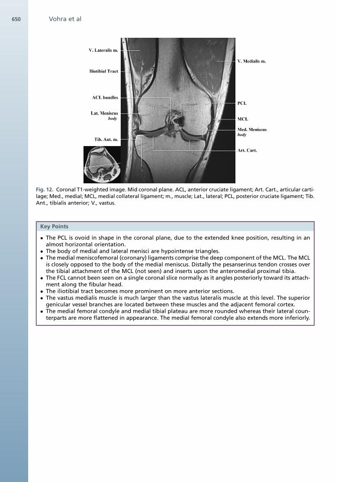
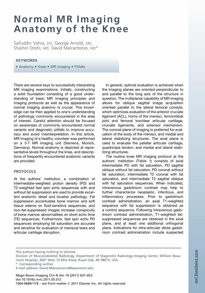
Fig. 12. Coronal T1-weighted image. Mid coronal plane. ACL, anterior cruciate ligament; Art. Cart., articular carti-lage; Med., medial; MCL, medial collateral ligament; m., muscle; Lat., lateral; PCL, posterior cruciate ligament; Tib.Ant., tibialis anterior; V., vastus.
Key Points
� The PCL is ovoid in shape in the coronal plane, due to the extended knee position, resulting in analmost horizontal orientation.
� The body of medial and lateral menisci are hypointense triangles.� The medial meniscofemoral (coronary) ligaments comprise the deep component of the MCL. TheMCL
is closely opposed to the body of the medial meniscus. Distally the pesanserinus tendon crosses overthe tibial attachment of the MCL (not seen) and inserts upon the anteromedial proximal tibia.
� The FCL cannot been seen on a single coronal slice normally as it angles posteriorly toward its attach-ment along the fibular head.
� The iliotibial tract becomes more prominent on more anterior sections.� The vastus medialis muscle is much larger than the vastus lateralis muscle at this level. The superior
genicular vessel branches are located between these muscles and the adjacent femoral cortex.� The medial femoral condyle and medial tibial plateau are more rounded whereas their lateral coun-
terparts are more flattened in appearance. The medial femoral condyle also extends more inferiorly.
Vohra et al650

Fig. 13. Double oblique T1-weighted image. Intercondylar notch parallel to Blumenstat’s line. AM, anteromedial;PL, posterolateral.
Key Point
� The ACL is composed of an anteromedial and posterolateral bundle, and attaches to the posterome-dial lateral femoral condyle, within the posterolateral aspect of the intercondylar notch, and to themedial tibial plateau, just anterolateral to the anterior tibial spine.
Normal MRI Anatomy of the Knee 651

Fig. 14. Normal variants and imaging pitfalls. (A) Sagittal proton density–weighted (PDW) image. Lateral aspectintercondylar notch.“Pseudotear” at lateral meniscal attachment of meniscofemoral ligament of Wrisberg. (B)Coronal PDW image. Immediately posterior to PCL. Meniscofemoral ligament of Wrisberg (in a different patient)extends from the posterior horn of the lateral meniscus to the medial femoral condyle, immediately posterior tothe PCL. (C) Sagittal PDW image. Lateral femorotibial compartment. Meniscal flounce, characterized by singlesymmetric fold along inner margin of the meniscus, more commonly seen in the medial meniscus. (D) Coronalintermediate T2-weighted image with fat suppression. Mid coronal plane. Irregularity and folding (meniscalflounce, in same patient) of inner margin of lateral meniscus can be mistaken for a tear on coronal images. Inci-dental note is made of severe chronic injury to the MCL (Pelligrini-Stieda).
Vohra et al652
Fig. 15. Differentiating iliotibial band friction syndrome and lateral parapatellar joint fluid. (A) Coronal interme-diate T2-weighted image with fat suppression. Mid coronal plane. Edema is seen within the soft tissues betweenthe iliotibial band (tract) and lateral femoral condyle in this patient with iliotibial band friction syndrome. (B)Coronal intermediate T2-weighted image with fat suppression. Mid coronal plane. Fluid is seen within the lateralparapatellar recess in this patient with a moderate joint effusion. Fluid is continuous with the joint effusion in allimaging planes.
Normal MRI Anatomy of the Knee 653
REFERENCES
1. Stoller DW, Lejay H, Holland BA. Technical advances
in musculoskeletal imaging. In: Barrett K, editor.
Magnetic resonance imaging in orthopaedics and
sports medicine, vol. 1. 3rd edition. Philadelphia:
Lippincott Williams & Wilkins; 2007. p. 1–28.
2. De Maeseneer M, Van Roy F, Lenchik L, et al. Three
layers of the medial capsular and supporting struc-
tures of the knee: MRI imaging-anatomic correlation.
Radiographics 2000;20:S83–9.
3. Stoller DW, Li AE, Anderson LJ, et al. The knee. In:
Barrett K, editor. Magnetic resonance imaging in
orthopaedics and sports medicine, vol. 1. 3rd
edition. Philadelphia: Lippincott Williams & Wilkins;
2007. p. 305–732.
4. Anderson MW. MR imaging of the meniscus. Radiol
Clin North Am 2002;40:1081–94.
5. Sanders TG, Linares RC, Lawhorn KW, et al. Oblique
meniscomeniscal ligament: another potential pitfall
for a meniscal tear- anatomic description and
appearance at MR imaging in three cases. Radi-
ology 1999;213:213–6.
6. Pfirrmann CW, Zanetti M, Hodler J. Joint magnetic
resonance imaging; normalvariantsandpitfalls related
to sports injury. Radiol Clin North Am 2002;40:167–80.
7. Manaster BJ, Andrews CL, Petersilge CA, et al. Hip &
pelvis: thighoverview. In:McAllisterL,editor.Diagnostic
and surgical imaging anatomy musculoskeletal.
1st edition. Salt Lake City: Amirsys Inc; 2006.
p. V190–279.
8. De Abreu MR, Kim HJ, Chung CB, et al. Posterior
cruciate ligament recess and normal posterior
capsular insertional anatomy: MR imaging of cadav-
eric knees. Radiology 2005;236:968–78.
9. Wangwinyuvirat M, Dirim B, Pastore D, et al. Prepa-
tellar quadriceps continuation: MRI of cadavers with
gross anatomic and histologic correlation. AJR Am J
Roentgenol 2009;192:W111–6.
10. Beaman FD, Peterson JJ. MR imaging of cysts,
ganglia, and bursae about the knee. Radiol Clin
North Am 2007;45:969–82.
11. Hennigan SP, Schneck CD, Mesgarzadeh M,
et al. The semimembranosus-tibial collateral liga-
ment bursa. Anatomical study and magnetic reso-
nance imaging. J Bone Joint Surg Am 1994;76(9):
1322–7.
12. Klecker RJ, Winalski CS, Aliabadi P, et al. The aber-
rant anterior tibial artery: magnetic resonance
appearance, prevalence, and surgical implications.
Am J Sports Med 2008;36:720–8.
13. El-Khoury GY, Bergman RA, Montgomery WJ. Knee.
In: Pope CF, Montgomery WJ, editors. Sectional
anatomy by MRI. 2nd edition. Philadelphia: Churchill
Livingstone Inc; 1995. p. 603–68.