Normal template 10 5707.doc · Web viewDTI Cleaner Fossil Fuels CO2 Capture and Storage in the EU...
74
Delivering sustainable solutions in a more competitive world Delete this text and insert client logo (optional, obtain approval first) CO 2 Capture and Storage in the EU ETS Monitoring and reporting guidelines for inclusion via Article 24 of the EU ETS Directive April 2007
Transcript of Normal template 10 5707.doc · Web viewDTI Cleaner Fossil Fuels CO2 Capture and Storage in the EU...

Delivering sustainable solutions in a more competitive world
Delete this text and insert client logo (optional, obtain approval first)
CO2 Capture and Storage in the EU ETS
Monitoring and reporting guidelines for inclusion via Article 24 of the EU ETS Directive
April 2007
www.erm.com

DRAFT REPORT
DTI Cleaner Fossil Fuels

CO2 Capture and Storage in the EU ETSMonitoring and reporting guidelines for inclusion via Article 24 of the EU ETS Directive
May 2007
Prepared by: Paul Zakkour
This report has been prepared by Environmental Resources Management the trading name of Environmental Resources Management Limited, with all reasonable skill, care and diligence within the terms of the Contract with the client, incorporating our General Terms and Conditions of Business and taking account of the resources devoted to it by agreement with the client.
We disclaim any responsibility to the client and others in respect of any matters outside the scope of the above.
This report is confidential to the client and we accept no responsibility of whatsoever nature to third parties to whom this report, or any part thereof, is made known. Any such party relies on the report at their own risk.
For and on behalf of Environmental Resources Management
Approved by: __________________________Signed: ________________________________Position: _______________________________Date: __________________________________

1 INTRODUCTION 1
1.1 BACKGROUND TO CCS OPERATIONS 11.2 BACKGROUND TO CCS IN THE EU ETS 21.3 AIMS, OBJECTIVES AND SCOPE 61.4 STRUCTURE 71.5 DEFINITIONS USED 7
2 DEVELOPING AN ACTIVITY OR INSTALLATION DEFINITION 8
2.1 OVERVIEW 82.2 ISSUES TO CONSIDER FOR CCS IN THE EU ETS VIA ARTICLE 24 82.3 EMISSION SOURCES ACROSS A CCS CHAIN 92.4 DEFINING INSTALLATION BOUNDARIES FOR THE OPT-IN UNDER ARTICLE
24 182.5 PROPOSED ACTIVITY DEFINITION FOR THE ARTICLE 24 OPT-IN 202.6 OPTIONS FOR THE TREATMENT OF CCS IN PHASE III 202.7 CONSIDERATIONS IN THE CONTEXT OF BROADER REGULATORY
DEVELOPMENTS 212.8 SUMMARY OF FINDINGS 21
3 DEVELOPING ACTIVITY / INSTALLATION SPECIFIC MONITORING AND REPORTING GUIDELINES 22
3.1 OVERVIEW 223.2 ISSUES TO CONSIDER FOR INCLUDING CCS IN THE EU ETS 223.3 OTHER ACCOUNTING METHODOLOGIES FOR CO2 CAPTURE AND STORAGE
223.4 ISSUES TO CONSIDER FOR MONITORING AND REPORTING IN THE EU ETS
233.5 ACTIVITY SPECIFIC GUIDELINES FOR CO2 CAPTURE 233.6 ACTIVITY SPECIFIC GUIDELINES FOR CO2 TRANSPORT 243.7 ACTIVITY SPECIFIC GUIDELINES FOR CO2 INJECTION AND STROAGE 243.8 SPECIFIC ISSUES FOR ENHANCED OIL RECOVERY PROJECTS USING CO2 243.9 SUMMARY OF FINDINGS 26
4 OTHER ISSUES FOR CCS INCLUSION 27
4.1 OVERVIEW 274.2 ALLOCATION 274.3 IMPACTS ON INCUMBENTS 274.4 OPT-IN AND OPT-OUTS 274.5 ISSUES FOR NEW ENTRANTS 27
5 Considerations for EU ETS Phase III 28
ENVIRONMENTAL RESOURCES MANAGEMENT DTI1

ENVIRONMENTAL RESOURCES MANAGEMENT DTI2

1 INTRODUCTION
This report has been prepared by Environmental Resources Management (ERM), over the period October 2006-May 2007. The report outlines guidelines for monitoring and reporting of emissions from carbon dioxide (CO2) capture and storage (CCS) under the EU Emissions Trading Scheme (EU ETS) (1) . It has been completed for – and working in conjunction with – the UK Department of Industry (DTI) and the UK Department for Environment Food and Rural Affairs (Defra).
Contributions in-kind have also been received from BP in respect of certain specific issues posed by the Peterhead-Miller project, and certain elements regarding the enhanced oil recovery element of that project.
The work represents part of ongoing efforts by the UK government to create an enabling legal framework for CCS projects in the UK and the European Union. In particular the UK government is committed to this effort as part of the support for proposed CCS projects that could be operational before the end of the EU Emissions Trading Scheme (EU ETS) (2) Phase II in 2012.
Discussions and positions of various other key stakeholders in the project also been considered, including the European Commission – DG Environment, Defra legal service, the UK Emissions Trading Group, and the CCS working group of the International Emissions Trading Association (IETA).
1.1 Background to CCS operations
In order to maintain the focus of this report, a comprehensive review of CCS technologies is not presented here. Useful background information can be found in a number of sources, such as:
the Intergovernmental Panel on Climate Changes (IPCC) Special Report on Carbon Dioxide Capture and Storage (SRCCS) (3);
publications from the IEA Greenhouse Gas Research & Development Programme; and,
The DTI report: Developing Monitoring, Reporting and Verification Guidelines for CO2 Capture and Storage in the EU ETS (4).
1(?) This report only considers geological storage of CO2, but not oceanic storage i.e. storage of CO2 directly in the water column.2(?) As laid out in Directive 2003/87/EC.3(?) IPCC 2006 Special Report on Carbon Dioxide Capture and Storage. Cambridge University Press.4(?) DTI 2005. Developing Monitoring, Reporting and Verification Guidelines for CO2 Capture and Storage Under the EU ETS. Report No. Coal R277, DTI/ Pub 05/583, prepared by ERM and DNV.
ENVIRONMENTAL RESOURCES MANAGEMENT DTI1

A summary of CCS technologies, potential and outlooks is provided below (Box 1.1).
Box 1.1 Overview of CCS technologies
1.2 Background to CCS in the EU ETS
The key criterion for including CCS operations in the EU ETS is that captured and transferred CO2 from qualifying installations in the scheme to CO2 storage sites is recognised and counted as CO2 that
ENVIRONMENTAL RESOURCES MANAGEMENT DTI2
CCS is a process consisting of the separation of CO2 from industrial and energy-related sources, transport to a storage location and long-term isolation from the atmosphere.
Methods of CO2 capture include:
Post-combustion capture, where the CO2 from flue gases exiting combustion or process plant is captured using solvent absorption technologies;
Pre-combustion capture, where a syngas is generated using a steam reformer, which is then split into H2 and CO2 using solvent-based capture technologies; and,
Oxyfuel combustion processes, where a relatively pure CO2 stream exits the combustion process, which can be directly compressed for transport and storage purposes with a minimum level of treatment;
Transportation in pipelines is the only likely cost-effective means of transporting the large volumes of CO2 associated with industrial scale CCS operations.
Potential storage sites include:
Depleted oil and gas reservoirs Operational oil and gas reservoirs Saline formations (deep brine bearing geological strata) Coal seams
CCS is considered as an option in the portfolio of mitigation actions for stabilisation of atmospheric greenhouse gas (GHG) concentrations. The IPCC SRCCS concluded that:
Available evidence suggests that, worldwide, it is likely there is a technical potential of at least about 2,000 GtCO2 of storage capacity in geological formations. In most scenarios for stabilization of atmospheric GHG concentrations between 450 and 750 ppmv CO2…CCS contributes 15-55% to the cumulative mitigation effort worldwide until 2100.
The IPCC also conclude that:
With appropriate site selection based on available sub-surface information, a monitoring program to detect problems, a regulatory system and the appropriate use of remediation methods to stop or control CO2 releases if they arise, the local health, safety and environment risks of geological storage would be comparable to the risks of current activities such as natural gas storage, enhanced oil recovery and deep underground disposal of acid gas.
Observations from engineered and natural analogues as well as models suggest that the fraction retained in appropriately selected and managed geological reservoirs is very likely to exceed 99% over 100 years and likely to exceed 99% over 1,000 years.
As such, CCS technologies should be considered as a key tool in the portfolio of climate change mitigation technologies available in the first part of the 21st century.
CCS is a technology which reduces emissions at source, and thus abating emissions from entering the atmosphere and contributing towards climate change. Its recognition in the EU ETS should be based on the fact emission reductions from CCS are real, measurable and verifiable in a complete, consistent and transparent way.

is not emitted (and subsequently therefore absolves to obligation on the installation operator to surrender EUAs equal to the amount not emitted). In order for this to be achieved, appropriate monitoring and reporting guidelines need to be approved which can establish a “chain of custody” for the CO2 from source to storage, providing the basis for accounting of any emissions of the captured CO2 across the CCS chain, and subsequent allocation of the responsibility to make good these emissions. In the absence of such guidelines, captured CO2 could simply be exported off-site from the installation and vented elsewhere, ultimately impacting on the environmental integrity of the scheme.
1.2.1 Treatment of CCS in Phase I of the EU ETS
In January 2004, the European Commission (EC) produced guidelines for monitoring and reporting of greenhouse gas emissions from qualifying installations in the EU ETS Directive (1) (MRGs). No specific guidance was provided in the MRGs for monitoring and reporting of emissions from CCS, although Member States were invited to submit proposals for interim MRGs for consideration by the Commission (Box 1.2).
Box 1.2 Key text from Decision 2004/156/EC
In response, in 2004 the UK DTI commissioned ERM and DNV to develop monitoring and reporting guidelines under the guidance of an ad hoc group of experts, based on this remit (2). These guidelines suggested that a yet-to-be established permitting regime for transport and storage could provide the basis for creating a chain of custody for the CO2 from capture to storage.
Under such a regime, the permit would require transport and storage site operators to monitor and report any emissions across the chain from transport and injection back to the exporting
1(?) Decision 2004/156/EC establishing guidelines for monitoring and reporting of greenhouse gas emissions pursuant to Directive 2003/87/EC (the EU ETS).2(?) DTI 2005. Developing Monitoring, Reporting and Verification Guidelines for CO2 Capture and Storage Under the EU ETS. op cit..
ENVIRONMENTAL RESOURCES MANAGEMENT DTI3
4.2.2.1.3 CO2 capture and storage
The Commission is stimulating research into the capture and storage of CO2. This research will be important for the development and adoption of guidelines on the monitoring and reporting of CO2 capture and storage, where covered under the Directive, in accordance with the procedure referred to in Article 23(2) of the Directive. Such guidelines will take into account the methodologies developed under the UNFCCC. Member States interested in the development of such guidelines are invited to submit their research findings to the Commission in order to promote the timely adoption of such guidelines.
Before such guidelines are adopted, Member States may submit to the Commission interim guidelines for the monitoring and reporting of the capture and storage of CO2 where covered under the Directive. Subject to the approval of the Commission, in accordance with the procedures referred to in Article 23(2) of the Directive, the capture and storage of CO2 may be subtracted from the calculated level of emissions from installations covered under the Directive in accordance with those interim guidelines.

installations, who would then have to reconcile these against the amount debited as transferred offsite.
For storage sites, the guidelines also proposed that the permitting regime would lay down requirements for the operator to make good any emissions from leaking storage sites by purchasing fungible emissions trading commodities (EU Allowances [EUAs], Certified Emission Reductions or Emission Reduction Units) equal to any monitored and reported emissions from the storage site; this would absolve liability on the exporting installation operator to surrender EUAs equal to any amounts leaked from the storage site, and place the obligation directly on the operator responsible for storing CO2. This consideration was essential in order to account for the potential temporal disconnect between when the CO2 was captured and the point in time when it may be re-emitted from the storage site.
1.2.2 More recent developments
In early 2006 the EC began a stakeholder driven process – via the European Climate Change Programme Work Group III (ECCP WGIII) – to assess the role of CCS in meeting EU climate change commitments. The Group recommended that recognition of CCS in the EU ETS was an important need in facilitating deployment of the technology (1).
In parallel, the EC undertook work to refine the MRG for application in Phase II of the EU ETS, based on the experience acquired during Phase I. In the draft final proposed MRG document for application in Phase I – launched in the latter part of 2006 (2) – the previous route for inclusion of CCS in the EU ETS outlined in Section 4.2.2.1.3 (Box 1.2) had been replaced in preference for inclusion of CCS in the EU ETS via Article 24 of the EU ETS Directive (Box 1.3).
Box 1.3 Key text of the preamble of Draft MRGs for Phase II
1.2.3 Rules for inclusion under Article 24 of the EU ETS Directive
Article 24 outlines the rules and procedures by which Member States may unilaterally include other activities, installations or greenhouse gases in addition to those listed in Annex I of the Directive from 2008 i.e. for Phase II of the EU ETS.
1(?) Final Report of Working Group III: Carbon Capture and Geological Storage. The 2nd European Climate Change Programme. 1st June 20062(?) Available from http://ec.europa.eu/environment/climat/emission/pdf/mrg_2006.pdf. (accessed April 2007).
ENVIRONMENTAL RESOURCES MANAGEMENT DTI4
Paragraph 24 of the preamble
(24) Recognition of activities relating to carbon capture and storage is not provided for in this Decision, but will depend on an amendment of Directive 2003/87/EC or by the inclusion of those activities pursuant to Article 24 of that Directive.

Box 1.4 Key elements of Article 24 of the EU ETS Directive
Thus, in order for CCS to be included in the EU ETS, the UK government will need to:
State its intention to include CCS operations in its Phase II National Allocation Plan (NAP): This has been undertaken as outlined in Section 4.3.2 of the UK’s draft NAP (1). In addition, Defra has written to Commissioner Dimas stating its intention the opt-in BP/Scottish & Southern Energy’s Peterhead-Miller (DF1) project, and potentially other CCS projects within Phase II (2);
Define the activity/installation type that it wishes to opt-in: this will form the basis for the inclusion of CCS operations, and define the subsequent scope of the MRGs;
Define the activity/installation type monitoring and reporting guidelines: based on the definition(s) developed above;
Evaluate and outline any potential effects on the internal market: None are presently envisaged. Such effects will be examined by the EC as part of the Impact Assessment of the ongoing CCS policy review;
Evaluate and outline any potential distortions of competition: This is also unlikely;
State any potential effects the proposal could have on the environmental integrity of the scheme: Impacts on the environmental integrity of the scheme arising from CCS projects are wholly dependent on the efficacy of the attendant monitoring
1(?) See: Defra (2007) EU Emissions Trading Scheme: Approved Phase II National Allocation Plan 2008-2012. Available at: http://www.defra.gov.uk/environment/climatechange/trading/eu/phase2/pdf/nap-phase2.pdf (accessed April 2007)2(?) Letter from Ian Pearson, UK Environment & Climate Change Minister to Commissioner Stavros Dimas. Unpublished.
ENVIRONMENTAL RESOURCES MANAGEMENT DTI5
Procedures for unilateral inclusion of additional activities and gases
1. From 2008, Member States may apply emission allowance trading in accordance with this Directive to activities, installations and greenhouse gases which are not listed in Annex I, provided that inclusion of such activities, installations and greenhouse gases is approved by the Commission in accordance with the procedure referred to in Article 23(2) [the comitology procedure], taking into account all relevant criteria, in particular effects on the internal market, potential distortions of competition, the environmental integrity of the scheme and reliability of the planned monitoring and reporting system.
[…]
2. Allocations made to installations carrying out such activities shall be specified in the national allocation plan referred to in Article 9.
3. The Commission may, on its own initiative, or shall, on request by a Member State, adopt monitoring and reporting guidelines for emissions from activities, installations and greenhouse gases which are not listed in Annex I in accordance with the procedure referred to in Article 23(2), if monitoring and reporting of these emissions can be carried out with sufficient accuracy.
4. In the event that such measures are introduced, reviews carried out pursuant to Article 30 shall also consider whether Annex I should be amended to include emissions from these activities in a harmonised way throughout the Community.

and reporting guidelines in detecting potential losses of CO2 across the CCS chain. This is the main focus of this report.
Precise modalities for inclusion of CCS projects in the UK in respect of allocation, opt-out and subsequent re-opt-in of incumbents, permit arrangements etc will also need to be elaborated.
1.2.4 The need to update the MRGs for CCS
Although the previous work by ERM and DNV outlined MRGs applicable for CCS, the modalities presented in that study were based upon the transfer provisions laid down in the MRG. Based on the permitting approach outlined in this study, the need to elaborate MRGs for the storage site was excluded. However, thinking on this matter has moved on since that time, and alternative approaches are under consideration for regulating pipelines and storage sites, based around their inclusion in the EU ETS (see Section XX below).
Given the new route for inclusion via Article 24, appropriate MRGs need to be elaborated to cover all parts of the CCS chain including storage sites.
1.3 Aims, Objectives and Scope
This aim of this report is to outline of appropriate monitoring and reporting guidelines applicable to CCS activities via the Article 24 opt-in route. It also includes consideration of specific monitoring and reporting issues presented by storage sites and enhanced oil recovery (EOR) operations, which were absent from the previous study. The latter is critical for the opt-in the BP/Scottish & Southern Energy Peterhead-Miller project, as this will involve the use of the CO2 in a miscible reservoir flood for the purpose of enhanced (tertiary) oil recovery.
In order to achieve this aim, the report objectives are:
To outline the activity/installation definition(s) that may be opted-in under Article 24 of the ETS Directive;
To identify general issues posed by CCS to the application of the current draft of the MRG for Phase II;
To defines activity/installation monitoring and reporting guidelines for all elements of a CCS operation, including EOR;
To outline some further considerations in respect of monitoring post-closure, and terms of liability transfer.
The document does not:
provide monitoring and reporting guidelines applicable to a specific installation. These must be developed based on the methodological approach outlined herein.
ENVIRONMENTAL RESOURCES MANAGEMENT DTI6

provide any indicative assessments of the overall accuracy of the methodologies outlined, as many of the technologies outlined herein are novel in nature. These will need to be determined on a case by case basis when applying the methodology outlined.
The report draws on the findings of previous research undertaken on this subject by ERM and DNV (1), and the reader is advised to read this report in conjunction with the findings presented here.
1.4 Structure
The report is structured in the following way:
Section 2 – outlines possible options for an activity/installation definition that may be opted-in under Article 24 of the ETS Directive;
Section 3 – outlines activity/installation specific guidelines, based on the definition outlined in Section 2;
Section 4 – considers other issues posed by the modalities for inclusion of CCS in the EU ETS.
1.5 Definitions used
[tbc]
1(?) DTI 2005. Developing Monitoring, Reporting and Verification Guidelines for CO2 Capture and Storage Under the EU ETS.op cit.
ENVIRONMENTAL RESOURCES MANAGEMENT DTI7

2 DEVELOPING AN ACTIVITY OR INSTALLATION DEFINITION
2.1 Overview
As outlined above (Section 1.2), in order for CCS operations to be opted-in and recognised in the EU ETS, appropriate activity/installation definition must be outlined. In order to develop a definition of a CCS activity, it is important to consider firstly the emission sources which might be included within the definition of the CCS activity, and subsequently, how these emission sources determine the boundary of the CCS activity. These two elements form the basis for developing an activity definition suitable for CCS.
Based on these criteria, this section presents:
the issues posed by Article 24 opt-in; the emission sources that will be present across a CCS chain,
and whether these are relevant to EU ETS accounting rules; based on the emission sources, the installation boundary for a
CCS activity; a proposed definition of a CCS activity, and issues for consideration beyond Phase II of the EU ETS.
2.2 Issues to consider for CCS in the EU ETS via Article 24
The present wording of the proposition under Article 24 poses two main complexities in so much as:
1. It is unclear how to define CCS as a new activity type when it involves a range of installation types (CO2 source, CO2 capture, transport, injection, storage), and therefore whether these need to be separate installations in their own right. In addition, the CO2 source plant may already be qualifying installations under the EU ETS (1). Therefore, CCS could involve deployment at incumbent installations in the EU ETS.
2. Consequently, this makes it rather unclear how an appropriate activity definition could be developed for CCS that is able to cross-cut existing activity/installation types. The current design of Annex I of the Directive involves defining Activity Types, with particular installations types nominated thereunder (see Annex I of Directive 2003/87/EC).
Notwithstanding these issues, there is not sufficient time prior to the beginning of Phase II of the EU ETS in which to amend the present Directive. As such there is a need for a practical solution to accommodate CCS operations post-2007. Therefore the following assumptions have been used as the basis for resolving these complexities:
1(?) And in the case of the Miller platform, also an incumbent in the EU ETS because of the power plant and flare(s) present on the platform.
ENVIRONMENTAL RESOURCES MANAGEMENT DTI8

Any incumbent installation planning to employ CCS will need to be opted-out then opt it back in under the newly defined activity type.
That inclusion via Article 24 route in Phase II will be based on a new activity type covering – as one installation – the following operations: the generation of CO2, the capture of generated CO2, its transportation via a pipeline, injection facilities (including facilities undertaking EOR operations) and the CO2 storage site.
These assumptions are consistent with the outcome of discussions between ERM, DTI, Defra and the EC and various legal advisors during the scoping phase of the project.
2.3 Emission sources across a CCS chain
The capture, transportation, injection and storage of CO2 as part of a CCS chain presents a number of opportunities for both the operational, accidental and background emissions of CO2. These can all be broadly categorised as fugitive emissions, in accordance with IPCC 1996 Guidelines on National Inventories (1).
The use of energy-intensive equipment and processes for CCS, such as capture, compression and injection, also presents opportunities for direct and indirect emissions of CO2 to occur.
Emissions sources across a CCS chain have been summarised by Haefeli et al (2) as shown below (Figure 2.1).
Figure 2.1 Potential sources emissions to be monitored across a CCS chain
Source: Haefeli et al (2003)
1(?) Revised 1996 IPCC Guidelines for National Greenhouse Gas Inventories. IPCC (1996)2(?) Haefeli, S., Bosi, M., Philibert, C. Carbon dioxide capture and storage issues – accounting and baselines under the United Nations Framework Convention on Climate Change (UNFCCC). International Energy Agency, Paris, 2004.
ENVIRONMENTAL RESOURCES MANAGEMENT DTI9

Depending on the accounting rules of the relevant emissions trading scheme – in this case the EU ETS – some or all of these emission sources may need to be monitored and reported. The different sources of CO2 emission that could occur across a CCS chain, and their relevance to CCS accounting rules, are reviewed in greater detail below. This includes a detailed discussion of specific issues presented by enhanced oil recovery (EOR) using CO2.
2.3.1 Direct emissions (fuel combustion)
Direct emissions refer to emission sources across the chain arsing from the primary combustion of fossil fuels as part of the activity. Emission sources include:
Emissions from the installation generating the CO2 due to imperfect capture of the CO2 or planned or emergency shutdown of the CO2 capture plant;
Emissions from gas-fired booster stations along the CO2 transport pipeline;
Emissions from any combustion installations generating power at the injection facility;
Careful consideration is needed regarding whether all of these emission sources fall within the scope of the EU ETS monitoring and reporting requirements, as discussed below.
2.3.2 The energy penalty for CO2 capture
Application of CO2 capture technologies presents a significant auxiliary energy penalty on the installation employing the plant, resulting in higher specific CO2 emissions generated per unit output of the installation relative to a standard configuration. Primarily, this is a result of:
the use of electrical power for fans, pumps, compressors etc and other mechanical drives associated with the CO2 capture plant;
energy requirements for oxygen production (e.g. for cryogenic air separation) in oxyfuel systems;
the use of steam for solvent regeneration in pre- and post-combustion capture systems; and,
energy used in pipeline head compressors.
Additional emissions generated as a consequence of these operations will be accounted for in the EU ETS through the application of the appropriate monitoring and reporting guidelines applicable to the installation, without the need for additional considerations.
Essentially, the key issue associated with the energy penalty in the EU ETS is one of allocation. Assuming that allocation will be made on the basis of a comparable installation not employing CO2 capture, then there is no risk of ‘over-rewarding’ the installation by taking
ENVIRONMENTAL RESOURCES MANAGEMENT DTI10

into account these extra emissions in its allocation baseline. Working on the basis that the overwhelming amount of these emissions will be captured and stored, and thus not emitted and recognised as such in the EU ETS, then there are no issues presented by the energy penalty under the EU ETS.
2.3.3 Fugitive emissions (venting and leaks)
Emissions of CO2 could occur as part of routine operational activities involved with CCS. Reasons might include:
leaks in CO2 capture system; emissions from solvent stripping operations, including imperfect
stripping of the solvent; pipeline maintenance, repair or blowdown; venting due to overpressure in the pipeline or at the storage site
installation due to injectivity problems or routine shutdowns, and;
inefficiencies and imperfections in CO2 capture and reinjection at the extraction wellhead in EOR activities.
Other sources of emissions across the chain could include background emissions due to:
leaking seals on blowing equipment required to force the flue gas into the adsorption tank;
leaking seals on solvent stripping tanks; leaking seals on compression equipment at the pipeline head; pipeline fracture or rupturing; leaking seals on pipeline joints and pipeline booster stations; leaking seals on injection wellhead compressors, and; leakage from improperly sealed injection wellheads.
All of these emission sources should be monitored and accounted for within the EU ETS.
2.3.4 Seepage from storage reservoirs (seepage)
Post-injection seepage of CO2 back to the atmosphere from the storage site could also occur through subsurface processes such as diffusion through caprock or migration along fault lines and fissures. Natural analogues have demonstrated the ability of geological reservoirs to retain CO2 indefinitely or very long periods of time. The capacity for long-term storage depends strongly on the specific characteristics (primarily the trapping mechanisms present) of the storage reservoir into which the CO2 is being injected. Although short-term leakage could occur in some storage sites during early phases of injection due to changing parameters in the reservoir such as pressure most experts believe that properly selected reservoirs could store CO2 securely for very long periods of time. In this context, the IPCC SRCCS concluded that:
ENVIRONMENTAL RESOURCES MANAGEMENT DTI11

Observations from engineered and natural analogues as well as models suggest that the fraction retained in appropriately selected and managed geological reservoirs is very likely to exceed 99% over 100 years and is likely to exceed 99% over 1,000 years. (SPM, Point 25, pg. 14)
As such, it is probably most effective to consider that CO2 injected into geological storage sites is not emitted, and will not be emitted in the future, rather than trying to account for these emissions in some form of present day value (e.g. through application some kind of default or discounting approach which ring-fences a fixed amount of emissions that are not recognised as emissions reduced in order to provide for a contingency in the event of future possible leakage). It is particularly challenging in a policy context to try and apply a generic default or discount factor as there is no clear basis upon which to develop such a factor. Indeed, the IPCC SRCCS suggests that:
Today, no standard methodology prescribes how a site must be characterized. Instead, selections about site characterization data will be made on a site-specific basis, choosing those data sets that will be most valuable in the particular geological setting. (Chapter 5, Section 5.4.1.1, pg. 225)
Implying that it will not be possible to use generic default factors applicable to all storage sites.
Moreover, the IPCC SRCCS also implies that the possibility of seepage is infact a function of appropriate site selection and management, rather than any standard rate function. Therefore, assuming the implementation of an effective regulatory scheme governing site selection and management, then this consideration should be the basis for including CCS in the EU ETS (1).
Notwithstanding this conclusion, there remains a challenge in determining how the applicable timeframes in the EU ETS (e.g. annual accounting and reconciliation; five year periods) are can be aligned with the time frames associated with the potential for CO2 seepage to occur (100’s to 1000’s of years; Figure 2.2).
1(?) In this context, the EC is presently drafting regulatory proposals for the selection, operation, closure and after-care considerations for geological CO2 storage sites in the EU.
ENVIRONMENTAL RESOURCES MANAGEMENT DTI12

Figure 2.2 Milestones in a CCS chain under emissions trading schemes
ENVIRONMENTAL RESOURCES MANAGEMENT DTI13

Source: DTI (2005) op cit.
The most practicable solution for accounting for this temporal disjoint with the EU ETS will be to combine:
effective regulatory controls on site selection and operation within the EU;
effective monitoring of CO2 storage sites under the EU ETS via appropriate monitoring and reporting guidelines, with annual reporting in order to account for any seepage occurring, and
ENVIRONMENTAL RESOURCES MANAGEMENT DTI14
Milestones in a CCS project
Number of years 1 10 100
5 year periods of the
EU ETS
Project based mechanisms e.g.CDM crediting periods of
7-10 years
Detailed storage site assessment: every 10
years+?
Handling of long-term liability for a storage site by a host government.
Transfer of liability or end of licensing period 50-500 years?
Possibility of seepage of CO2 back to the atmosphere over
geological timescales?
1 yearsurrender EUAs annually under the
EU ETS.
The EU ETS Compliance year
Calendar / Compliance Year Previous year Current Compliance Year Following YearMonth Oct Nov Dec Jan Feb Mar Apr May Jun Jul Aug Sep Oct Nov Dec Jan Feb Mar Apr
1 JanCompliance year begins
28 FebEUAs must be issued by this
deadline
30 AprSurrender EUAs
for previous compliance year
31 DecCompliance year ends
31 MarDeadline for verification of Monitoring Report for
previous year
31 MarDeadline for verification of Monitoring Report for
current year
30 AprSurrender EUAs
for previous compliance year
The reconciliation period for trading to comply in a prior year is 1-30 April in
the following year.

any emissions arising from storage site seepage must be estimated and reconciled against any quantities of CO2 calculated as non-emitted by the source installation (which under the assumptions underlying this document, would mean the entire CCS chain as one installation type).
2.3.5 Indirect emissions (from bought-in power)
These relate to those emissions created by a CCS chain, but actually occur outside its immediate boundaries. Principally these relate to any imported electricity used for the activity, or the emission sources that the activity might create or displace. These might include:
indirect CO2 emissions associated with bought-in electricity or steam used for capture, transport or injection of CO2;
indirect CO2 emissions associated with the energy used in manufacture of CO2 stripping agents;
These emission sources are not considered relevant under EU ETS accounting rules for the following reasons:
Where the components of CCS scheme are powered by bought-in electricity, this electricity is likely to have been generated at another qualifying installation included under the EU ETS e.g. an incumbent combustion installation. Its inclusion in the proposed methodology for an installation using CCS would represent ‘double counting’ of emissions in the EU ETS. This is consistent with the requirements of Draft Phase II MRGs, which states that:
Emissions associated with the production of heat or electricity imported from other installations shall not be assigned to the importing installation. (Section 4.2, pg. 17).
The CO2 emissions associated with the manufacture of CO2 stripping agents is not considered relevant under EU ETS rules. Moreover, it is likely that these agents will have been manufactured at a site qualifying as an installation under the EU ETS (such as a large chemicals manufacturing plant), and therefore, could also represent double counting.
2.3.6 Emissions of breakthrough CO2 in enhanced oil recovery
Installations undertaking enhanced oil recovery (EOR) using injected CO2 will present additional emission pathways and sources relative to standard CO2 storage operations. This arises as a consequence of the injected CO2 breaking through with the produced hydrocarbons. In principle, operators will separate out the breakthrough CO2 and reinject it with incoming captured CO2 from the pipeline. However, there will remain opportunities for emissions of to breakthrough CO2 occur across the system through a variety of different pathways. Key emissions sources for CO2 EOR operations include:
ENVIRONMENTAL RESOURCES MANAGEMENT DTI15

the oil-gas separation units and gas recycling plant, where fugitive emissions of CO2 could occur;
the flare stack, where emissions might occur due to the application of continuous positive purge systems (thus capturing the fugitive losses from the oil-gas separation plant) and under blowdown conditions during depressurisation of the oil production installation;
the onsite power plant, where the power plant is using indigenous field gas to power operations, which will be co-mingled with the injected CO2.
a dedicated CO2 purge system, which may be necessary as routing high concentration CO2 gases into a flare system will extinguish the flare.
A potentially further complicating factor for EOR operations is that injected CO2 will breakthrough mixed with indigenous reservoir CO2. In such cases, it is important to consider whether the indigenous reservoir CO2 constitutes a “regulated” emission under the EU ETS, or whether there is need to account separately for the indigenous CO2 compared with the breakthrough CO2.
Figure 2.3 Emission pathways for EOR operations
*Note: fugitive emissions of CO2 and hydrocarbon gas mixtures will in nearly all cases be caught in the gas containment system and released via the flare/purge safety system, as opposed to vented to atmosphere.
The additional emission pathways will all need to be included in a monitoring and reporting scheme for CCS activities involving EOR. However, notwithstanding such a conclusion, there are several factors that need to be taken into consideration, as follows:
ENVIRONMENTAL RESOURCES MANAGEMENT DTI16
Oil reservoir
Injected CO2 stream Produced oil
Oil-gas separators
Onsite power plant
CHX + CO2
Flare stack
CHX + CO2
CO2 purge system
CO2 + CHX
CO2 recycle CO2 + CHX
TO ATMOSPHERE
Fugitive emissions*
CO2 + CHX
Breakthrough CO2 plus other hydrocarbon gases (CHX+CO2)

The onsite power plant at oil production installations (certainly for offshore installations on the UK continental shelf) are incumbent qualifying installations under Annex I Energy Activities – Combustion installations of Directive 2003/87/EC;
Flares are also captured under Energy Activities – Combustion installations in Annex I for Phase II of the EU ETS;
Conceivably, a dedicated CO2 purge source could also be captured in Annex I on the same basis as the flare, albeit with a need to clarify the definition of a flare or flare gas to also recognise non-combusted and/or vented emission sources;
For occupational health and safety reasons, all offshore platforms have a gas containment system with a positive purge system incorporated to prevent the accumulation of hydrocarbon gases which pose an explosion risk on the platform. For this reason, any fugitive emissions across the gas handling system will be routed to the flare or gas purge system, and thus do not represent an additional emission source on the installation.
Based on these conditions, a brief example of how emissions accounting for an installation employing EOR could work in practice, based on the BP Miller platform, is outlined below.
EOR accounting in practice
The Miller field is owned and operated by BP, and forms the cornerstone of the planned DF1 project, where CO2 from the Peterhead power plant will be captured and exported offshore via a pipeline to the Miller. The exported CO2 will primarily be stored in conjunction with EOR operations.
At Miller, the onsite power is provided by three duty gas-turbine power generation plants plus a peak load lopping turbine. The total installed capacity is approximately 3 x 100MW net rated input and 1 x 20 MW rated thermal input respectively. All turbines are presently powered by field gas arriving on the platform in association with produced oil (associated gas). Field gas from Miller already contains around 25% CO2, which is naturally occurring in the reservoir. All turbines are qualifying installations under Annex I of Directive 2003/87/EC Energy activities – Combustion installations, and therefore emissions from these units are all included under the EU ETS.
The turbines give rise to around 160,000-200,000 tCO2/yr (1), which makes it a Category B installation under EU ETS Monitoring and Reporting Guidelines minimum requirement rules. This has consequences for the way emissions from the turbine are calculated as described below (Box 2.5).
1(?) Based on UK National Allocation Plan data.
ENVIRONMENTAL RESOURCES MANAGEMENT DTI17

Box 2.5 Current accounting of emissions from the power plant on the Miller platform
The Miller platform also operates gas flare for safety reasons, which combusts around 45,000-120,000 m3 of purge gas/yr, giving rise to 50,000-100,000 tCO2/yr in flare gas emissions. This also means that it falls within Category B under the EU ETS Monitoring and Reporting tier system, and is subject to the same monitoring and reporting procedure as described above (Box 2.5).
Upon commencement of the CO2 EOR flood, the platform will continue to operate the same gas management regime. It is anticipated that breakthrough CO2 will be received at the platform for the first time approximately 3 years after commencing the CO2 flood. Following this, a continued upward trend in the volume of breakthrough CO2 is anticipated, leading to an increasing ratio of CO2 to indigenous field gas (from the initial base of 25% naturally occurring in the field gas). After a period of time, the field gas will contain too high a fraction of CO2 to be combustible, at which point, gas for field power will be imported, and all the produced field gas will be reinjected into the reservoir (Figure 2.4). Fugitive emissions, routine platform blowdown, and emergency releases will continue to route the field gas to the flare or CO2 purge system (Figure 2.3), and therefore also continue to be monitored and reported under the EU ETS.
ENVIRONMENTAL RESOURCES MANAGEMENT DTI18
As the both the Miller power plant and flare qualify as Category B minimum requirement rules, emissions are calculated using Tier 2a/2b activity data and/or emission factor approaches. This means that the gas is not directly analysed for monitoring and reporting purposes, but emissions are calculated based on the country specific net calorific values or supplier data (the latter is not relevant in this context). Consequently, the 25% CO2 content of the field gas is unlikely to be presently picked-up in the current Miller CO2 emissions accounting regime, and therefore, for all intents and purposes, does not constitute regulated CO2 in the EU ETS. In order to recognise the breakthrough CO2 in the power plant emissions, it is likely that a Tier 3 minimum requirements activity data and emissions factors will need to be applied. Tier 3 requires installations to directly sample fuel and determine its net calorific value, carbon content and emission factor according to standardised methods (see Section 13 of Annex I of the draft EU ETS MRGs for Phase II).

Figure 2.4 Field gas composition over time at Miller (illustrative)
Under this gas management regime, all emissions of breakthrough CO2 will be effectively captured within the scope of the EU ETS as combustion emissions from either the onsite power plant or the flare stack.
As a consequence, no new emissions sources are presented by breakthrough CO2, and therefore the environmental integrity of the scheme will be maintained i.e. no additional emission sources need to be included in the monitoring and reporting plan for the Miller platform specific to the EOR operation. Furthermore, as these emission sources are already in essence accounting for indigenous reservoir CO2 – albeit with some potential gaps associated with the way gas analysis is applied – then no additional complications arise regarding the split between “regulated” and indigenous CO2 i.e. the indigenous CO2 is already regulated as part of these emission sources.
Notwithstanding this conclusion, a number of additional elements will need to be incorporated in the monitoring and reporting guidelines to ensure effective accounting of emissions of breakthrough CO2, as follows:
Dedicated CO2 purge vent: any new CO2 purge vent will need to be monitored and reported under the EU ETS to ensure this emission source is accounted for in the monitoring and reporting
ENVIRONMENTAL RESOURCES MANAGEMENT DTI19
0%
50%
100%
Cessation of indigenous gas use
Fiel
d ga
s co
mpo
sitio
n (%
) USE STORAGE
CHX
injected
Indigenous CO2
Injected (breakthrough) CO2
Indigenous CHX
0 30Time (years)
Breakthrough CO2 first detected
Breakthrough CO2 to onsite power plant
All breakthrough CO2.
No indigenous gas.
All reinjected

protocol. For simplification, it is probably fair to consider a CO2 purge vent in the same way as a flare. In this context it is useful to note that the Norwegian Regulations Relating to Measurement of Petroleum for Fiscal Purposes and for Calculation of CO2-tax (The Measurement Regulations), 1 November 2001, NPD define “flare gas” as:
Flare gas: Natural gas burnt off or vented to the atmosphere.
This definition provides coverage for both venting and flaring operations, and could be adopted as the basis for including any vent streams on the same basis as flares. Presently the Phase II Monitoring and Reporting Guidelines do not include any definition for flares or flare gas.
Gas analysis: in order to ensure trueness in the monitoring and reporting of emissions from EOR operations it will be necessary to apply Tier 3 minimum requirements for activity data and emission factor. This will ensure that field gas used in combustion installations (both the power plants and flare or vent systems) accurately records the quantities of breakthrough CO2 emitted to atmosphere from these sources.
2.4 Defining installation boundaries for the opt-in under Article 24
The revised EU ETS MRGs for Phase II require that (1) :
The monitoring and reporting process for an installation shall include all emissions from all emission sources and/or source streams belonging to activities listed in Annex I to Directive 2003/87/EC, carried out at the installation, of greenhouse gases specified in relation to those activities, as well as from activities and greenhouse gases included by a Member State pursuant Article 24 of Directive 2003/87/EC.
All emissions sources within these boundaries are to be identified, described, and monitored and reported including specifying the monitoring methodology and frequency in accordance with the approved monitoring plan for the installation.
Taking into consideration the various emissions sources identified in previous sections, boundaries of the opted-in installation can be considered to encompass:
The installation generating the CO2, based on qualifying criteria laid down in Annex I of Directive 2003/87/EC, including the capture technology applied at a qualifying installation;
1(?) Revised MRGs. Section 4.3, pg. 16
ENVIRONMENTAL RESOURCES MANAGEMENT DTI20

Pipelines installations transporting captured CO2 from qualifying installations, including emissions from any booster stations employed on the pipeline;
Injection and storage installations receiving CO2 from pipeline(s); and including the above ground installation, well(s), the subsurface storage complex covering inter alia: the target formations, the caprock and any spill-points in the reservoir etc. This also includes any emissions associated with breakthrough CO2 in enhanced hydrocarbon recovery activities.
This forms the basis for defining the opted-in installation(s) under Article 24 of Directive 2003/87/EC. Prior to providing a definition of the installation for the opt-in, there are several ambiguities in the context of CCS that need be reviewed, as outlined below.
2.4.1 Treatment of intermediate booster facilities on pipelines
There remains some ambiguity about whether intermediate compression stations would be considered to part of a CCS activity/installation under the terms described above. There are several competing views on the matter as follows:
1. That a booster facility is technically connected to a single CCS installation (or a separate pipeline installation) and therefore its emissions should be included as part of the installations inventory. No additional allocation would be given to cover booster station emissions as, in principle, CCS is near zero-emission technology and no additional allowances should be allocated to the technology; and/or,
2. That a booster facility be treated as installation in its own right if it exceeds the 20MW rated thermal input threshold in Annex I of Directive 2003/87/EC, or be totally excluded from the accounting regime if it is below this threshold; and/or,
3. An alternative might be that smaller booster stations (<20MW) are included as per point 1. with or without an allocation, whilst larger (>20MW) plant are included in their own right as separate combustion installations. However, this would be difficult to implement in practice due to the creation of a perverse incentive to build larger turbines in order to gain an allowance allocation.
In the previous study by ERM and DNV on inclusion of CCS in the EU ETS, it was concluded that emissions from any gas powered booster stations on the pipeline would not be reconciled with the exporting installation (i.e. be excluded from its emissions inventory), unless they were qualifying EU ETS installations in their own right (i.e. as combustion installations with a rated thermal input greater than 20MW).
However, considering the full chain of activities would be opted-in as one installation via Article 24, then there is probably a need to consider emissions from such installations in a different way, based
ENVIRONMENTAL RESOURCES MANAGEMENT DTI21

in the installation definition provided for in the ETS Directive (Box 2.6).
Box 2.6 Definition of an installation under Directive 2003/87/EC
As the booster station would be a directly associated activity with a technical connection to the source-capture-transport-injection-storage installation, and they could have an effect on emissions, then it seems emissions from this source would need to be included in the overall scheme inventory.
The question on whether these installations would or would not receive additional allocation remains open-ended, and is a matter of policy which may be best resolved through stakeholder consultation. One issue to consider on this matter is that compression facilities at a combustion installation employing CCS would not receive any additional allocation (see Section 2.3.2), and thus providing extra allowances for booster stations may incentivise operators to move the compression facility at the pipeline head outside of the combustion installation in order to receive an allocation (1). Further considerations on this matter also include that:
it may be effective to provide zero allocation to booster stations along the pipeline such that it could conceivably incentivise operators to capture additional emissions from these sources; and,
these concerns would become largely irrelevant under a allowance auctioning system.
2.4.2 Storage site boundaries
<tbc>
2.5 Proposed activity definition for the Article 24 opt-in
Based on the assumptions and conclusions outlined above (Section 2.2), the following elements are considered to form part of a complete CCS activity:
Based on inclusion of these elements, the following is proposed as a definition for the opt-in for CCS activities:
CCS Activities
1(?) Which may not be the optimal design for the plant in terms of configuration and efficient use of energy, although thic could conceivably be caught under future IPPC permitting considerations.
ENVIRONMENTAL RESOURCES MANAGEMENT DTI22
Article 3 Definitions
‘installation’ means a stationary technical unit where one or more activities listed in Annex I are carried out and any other directly associated activities which have a technical connection with the activities carried out on that site and which could have an effect on emissions and pollution;
Installations included in Annex I of Directive 2003/87/EC employing CO2 capture technologies.
Pipeline installations
<tbc>
2.6 Options for the treatment of CCS in Phase III
A more practical approach for Phase III of the EU ETS would be to include elements of the CCS chain as separate installation in the EU ETS in their own right in the following way:
Source and capture: the addition of a capture plant to an incumbent installation would be considered as a simple plant modification, and would be caught under the existing obligations in Directive 2003/87/EC as a “…directly associated activity with a technical connection with the activities...” (Box 2.6) and thus would not require any opt-in. Allocation of allowances to this installation would be on the same basis as for other incumbent installations in the same sector not employing CO2 capture;
Transportation: pipelines carrying CO2 for the purpose of storage be considered as a new type of installation in the EU ETS, and allocated zero allowances. This would create a monitoring and reporting obligation for the operator under Article 6 of Directive 2003/87/EC, and also a requirement to surrender allowances equal to monitored and reported emissions in each calendar year, in accordance with the Greenhouse Gas Permit issued under Articles 6(2)(e) of Directive 2003/87/EC.
Injection and storage: again these would be considered as a separate installation in the EU ETS, be given a zero allocation, and would face the same obligations as outlined for transportation above. This would also include installations employing EOR.
2.7 Considerations in the context of broader regulatory developments
<tbc>
ENVIRONMENTAL RESOURCES MANAGEMENT DTI23

3 DEVELOPING ACTIVITY / INSTALLATION SPECIFIC MONITORING AND REPORTING GUIDELINES
3.1 Overview
Based on the activity definition outlined previously (Section XX), there is a need to develop activity specific monitoring and reporting guidelines for the installation(s) identified within the opt-in activity description. In this context, it will be necessary to split the guidelines between the different installations making up the new activity as follows:
CO2 generation and capture; CO2 transportation; CO2 storage; Enhanced oil recovery.
Prior to the outlining of the specific guidelines, there are several general issues linked to EU ETS MRGs that need to be taken into consideration specific for application of the guidelines to CCS activities.
3.2 General issues to consider for including CCS in the EU ETS
There is are several new terms and definitions contained in the revised MRGs for Phase II of the EU ETS which will need careful consideration with respect to developing activity specific guidelines for CCS installations. Key factors to take into account include:
Emission types included in the EU ETS. Presently The MRGs only deal with combustion and process emissions, which may not be applicable to CCS operations and could require new definitions to be developed;
New criteria for minor and de minims source streams. New rules allow monitoring to be waived for very minor source streams, which may be in conflict with the MRG approach for CCS, where source streams will by definition intentionally small or non-existent;
The potential to apply new ‘fall-back’ approaches. This is designed to reduce the monitoring burden on small emitters, but could conflict with the need for reasonably intensive monitoring of potentially not emitting streams;
Rules for modifying monitoring methodologies. It will be important to maintain flexibility in storage site monitoring plan design, taking into consideration the embryonic and iterative nature of the technologies;
Cost effectiveness considerations. There will be a need to ensure that monitoring plans for storage sites do not impose excessive costs on operators.
ENVIRONMENTAL RESOURCES MANAGEMENT DTI24

These points are discussed in greater detail below.
3.2.1 Types of emission included in the EU ETS
Presently the EU ETS MRGs describe cover the inclusion of the following types of emissions:
“emission source” means a separately identifiable part (point or process) of an installation from which relevant greenhouse gases are emitted;
“combustion emissions” means greenhouse gas emissions occurring during the exothermic reaction of a fuel with oxygen;
“process emissions” means greenhouse gas emissions other than combustion emissions occurring as a result of intentional and unintentional reactions between substances or their transformation, including the chemical or electrolytic reduction of metal ores, the thermal decomposition of substances, and the formation of substances for use as product or feedstock;
Certain emissions that may occur across the CCS chain – such as venting from the pipeline, fugitive leaks from compressors, or seepage from the storage site – do not conceivably fall into any of these categories, although the MRGs do require monitoring of emissions during start-up, shut-down and emergency situations (1), so a requirement to monitor these emissions sources is in essence captured thereunder.
Therefore, in order for these types of emissions to be accounted for, it may be appropriate to define the following types of emissions in the MRGs for the opt-in:
“vented emissions” means greenhouse gas emissions from intentional or unintentional release of captured relevant greenhouse gases due to routine or emergency operations.
“fugitive emissions” means greenhouse gas emissions from routine chronic or sporadic unintentional releases of captured relevant greenhouse gases as a result of leaking valves, flanges, seals etc.
“seepage emissions” means greenhouse gas emissions from intentional or intentional release of captured relevant greenhouse gases from a CO2 geological storage site to the atmosphere.
This would capture all the relevant emissions types from the new categories of emissions source points potentially arising across a CCS chain, as outlined in the Section 2 of this report.
1(?) Section 4.1, para 4, pg 17.
ENVIRONMENTAL RESOURCES MANAGEMENT DTI25

3.2.2 New criteria for minor and de minims source streams
The revised MRGs also include provisions for the following types of source streams:
“De-minimis source streams” means a group of minor source streams selected by the operator and jointly emitting 1 ktonnes of fossil CO2 or less per year or that contribute less than 2% (up to a total maximum contribution of 20 ktonnes of fossil CO2 per year) of total annual emissions of fossil CO2 of that installation before subtraction of transferred CO2, whichever is the highest in terms of absolute emissions;
“Minor source streams” means those source streams selected by the operator to jointly emit 5 ktonnes of fossil CO2 or less per year or to contribute less than 10% (up to a total maximum contribution of 100 ktonnes of fossil CO2 per year), to the total annual emissions of fossil CO2 of an installation before subtraction of transferred CO2, whichever is the highest in terms of absolute emissions.
For source streams identified as falling within these categories the operator may, subject to approval by the competent authority, select as a minimum the tier 1 level for the variables used to calculate emissions from minor source streams and apply approaches for monitoring and reporting using his own no-tier estimation method for de-minimis source streams (1). In other words, more relaxed monitoring requirements may be applied to these streams.
Whilst this serves to ease the monitoring burden on operators, for CCS emissions where the focus of monitoring is on potential emission sources and ideally no emissions be detected, it should not provide the basis for reducing monitoring requirements, especially for storage sites.
3.2.3 Rules for modifying monitoring methodologies
Under the revised MRGs, the following rules apply to changes in a methodology (2):
The monitoring methodology shall be changed if this improves the accuracy of the reported data, unless this is technically not feasible or would lead to unreasonably high costs.
A substantial change to the monitoring methodology as part of the monitoring plan shall be subject to the approval of the competent authority if it concerns:
a change of the categorisation of the installation as laid down in table 1,
1(?) Revised EU ETS MRGs op cit.. Section 5..2, pg. 21.2(?) Revised EU ETS MRGs op cit.. Section 4.3, pg. 19.
ENVIRONMENTAL RESOURCES MANAGEMENT DTI26

a change between the calculation based or the measurement based methodology used to determine emissions,
an increase of the accuracy of the activity data or other parameters (where applicable) which implies a different tier level,
All other changes and proposed changes in monitoring methodology or the underlying data sets shall be notified to the competent authority without undue delay after the operator has become aware of it or could in all reasonableness have become aware of it, unless otherwise specified in the monitoring plan.
As outlined in Section XX of this report where the monitoring methodology for storage sites is described, there is a need to adopt an iterative approach for storage site monitoring, based around the principle of “adaptive learning”. This is because after injection commences, there may be a need to adapt a monitoring plan as the understanding of the subsurface behaviour of the CO2 plume evolves. The main consideration is, therefore, that sufficient flexibility is provided for operators who need to adapt their monitoring plan for a storage site.
3.2.4 Cost effectiveness considerations
The revised MRGs include provisions for cost effectiveness as follows (1):
Cost effectiveness. In selecting a monitoring methodology, the improvements from greater accuracy shall be balanced against the additional costs. Hence, monitoring and reporting of emissions shall aim for the highest achievable accuracy, unless this is technically not feasible or will lead to unreasonably high costs. The monitoring methodology itself shall describe the instructions to the operator in a logical and simple manner, avoiding duplication of effort and taking into account the existing systems in place at the installation.
They also include a definition of unreasonable costs as follows:
“Unreasonable costs” means costs of a measure disproportionate to its overall benefits as established by the competent authority. In respect to the choice of tier levels the benefit may correspond to the value of the allowances corresponding to an improvement of the level of accuracy, or for measures increasing the quality of reported emissions but without direct impact on accuracy, a fraction exceeding an indicative threshold of 1% of the average value of the allowances allocated to the installation for the previous trading period. For installations without this history, data from representative
1(?) Revised MRGs, Section 3, pg. 16
ENVIRONMENTAL RESOURCES MANAGEMENT DTI27

installations carrying out the same or comparable activities are used as reference and scaled according to their capacity.
There will be a need to ensure that monitoring plans for storage sites do not impose excessive costs on operators. This is a particularly prudent consideration given that, in theory, a very detailed monitoring plan could be developed for the storage site involving highly expensive methods such as intensive 4D-seismic etc. However, intensive monitoring approaches are unlikely to prove cost effective and as such there is probably a need for an operator to outline his rationale based around cost-effectiveness considerations for any selected approach for a storage site monitoring plan.
3.2.5 Approaches to emissions methodologies
Two different approaches for monitoring emissions from qualifying installations are allowed for under Annex IV of Directive 2003/87/EC, as follows (1) :
a calculation based methodology, determining emissions from source streams based on activity data obtained by means of measurement systems and additional parameters from laboratory analyses or standard factors
a measurement based methodology, determining emissions from an emission source by means of continuous measurement of the concentration of the relevant greenhouse gas in the flue gas flow and of the flue gas flow.
In addition the MRGs outline that
The operator may propose to use a measurement based methodology if he can demonstrate that:
it reliably results in a more accurate value of annual emissions of the installation than an alternative calculation based methodology avoiding unreasonable costs; and
the comparison between measurement and calculation based methodology is based on an identical sets of emission sources and source streams.
A discussion of the most appropriate approaches for CCS is provided in the previous report by ERM (2), and the reader is referred to that report for a detailed discussion of these issues. In this report it was concluded that:
…in weighing up the options of:
1(?) Revised MRGs. Section 4.2, pg. 172(?) DTI 2005. Developing Monitoring, Reporting and Verification Guidelines for CO2 Capture and Storage Under the EU ETS.op cit.
ENVIRONMENTAL RESOURCES MANAGEMENT DTI28

i) trying to apply emissions factors to all the different elements of a CCS chain in light of the breadth of uncertainties posed by the calculation/emissions factor based approach, with
ii) the potential inequity of the measurement/mass balance approach, and the potential issues it presents over liability for fugitive emissions,
it was concluded by the ad hoc group that the latter would prove more appropriate and acceptable in the near term.
These considerations excluded approaches to monitoring potential emissions from storage sites as this was excluded from the MRGs in the approach adopted in that report.
Measurement-based methodologies are the only technology that may be applied to estimate emissions from CO2 from storage sites. This view is reinforced by approach for geological storage site emissions estimates outlined in the 2006 IPCC Guidelines for National Greenhouse Gas Inventories, Volume 2, Chapter 5 concerning Carbon Dioxide Transport, Injection and Storage. This document advocates the use of a Tier 3 (i.e. project specific monitoring) emissions estimation process to:
…support zero emissions estimates and also to detect leakage, even at low levels, if it occurs (1).
The IPCC approach is described in greater detail below.
2006 IPCC Guidelines for National Greenhouse Gas Inventories
Within the 2006 GHG Guidelines, a schematic is presented outlining the monitoring procedure for determining storage site emissions (Figure 3.5).
1(?) Section 5.7.2. pg 5.17.
ENVIRONMENTAL RESOURCES MANAGEMENT DTI29

Figure 3.5 Monitoring procedure - 2006 IPCC GHG guidelines
Source: 2006 IPCC Guidelines for National Greenhouse Gas Inventories, Volume 2, Chapter 5
The process outlined involves the development of an assurance-based scheme to demonstrate good storage site selection, evaluation of risks of containment loss, demonstration of a bespoke (or “adequate”) monitoring plan, adaptive learning principles, and monitoring and reporting. As such, it creates a de facto approvals process for appropriate CO2 storage site selection, risk assessment, and monitoring design.
The 2006 GHG Guidelines provide further details on the series of methodological steps that need to be undertaken in to compiling the inventory, including:
1. Identify and document all geological storage operations in the jurisdiction
2. Determine whether an adequate geological site characterization report has been produced for each storage site, including:
a. Identify and characterise potential seepage pathways such as faults and pre-existing wells
b. Quantify the hydrogeological properties of the storage system
c. Include enough data to compile a geological Earth model of the site and surrounding zone
3. Determine whether the operator has assessed the potential for leakage at the storage site, including:
a. Including likely timing and flux of any fugitive emissionsb. Demonstration that seepage is not expectedc. Short-term simulations to predict site behaviour during
and beyond the injection (decades)
ENVIRONMENTAL RESOURCES MANAGEMENT DTI30

d. Long-term simulations to predict the fate of CO2 over centuries to millennia
e. Sensitivity analysisf. Design of the monitoring programmeg. Update with new data and operational changes
4. Determine whether each site has a suitable monitoring plan. This includes:
a. Measurement of background fluxes at the storage site and potential emission points in the surrounding zone
b. Continuous measurement of the mass of CO2 injectedc. Monitoring to determine emission from the injection
systemd. Monitoring to measure fluxes through the seabed or
ground surface, including wells and springse. Post injection monitoringf. Incorporation of improved monitoring techniquesg. Periodic verification
5. Collect and verify annual emissions from each site [and perform history matching].
The procedures outlined under Step 4 provide an international standard by which storage site monitoring methodologies should be developed.
In terms of operationalising the IPCC guidelines, efforts were undertaken during 2006 to develop these in guidelines for the Clean Development Mechanism (CDM) project-based emissions trading scheme (1). This work developed the high level IPCC procedure into a formalised methodological approach which can be applied to a specific storage site in order to arrive at an appropriate monitoring plan. The work undertaken for that purpose is used in this report as the basis for EU ETS MRGs for storage sites, outlined below (Section 3.5).
3.2.6 Information requirements of a monitoring plan
Following application of the appropriate methodology to the appropriate installation, the revised MRGs require the following information to be set in the monitoring plan:
the description of the installation and activities carried out by the installation to be monitored;
information on responsibilities for monitoring and reporting within the installation;
a list of emissions sources and source streams to be monitored for each activity carried out within the installation;
a description of the calculation based methodology or measurement based methodology to be used;
1(?) IEA Greenhouse Gas R&D Programme. Carbon Dioxide Capture and Storage in the Clean Development Mechanism: Possible Approaches to CDM Methodology Issues. ERM/Shell, April 2007.
ENVIRONMENTAL RESOURCES MANAGEMENT DTI31

a list and description of the tiers for activity data, emission factors, oxidation and conversion factors for each of the source streams to be monitored;
a description of the measurement systems, and the specification and exact location of the measurement instruments to be used for each of the source streams to be monitored;
evidence demonstrating compliance with the uncertainty thresholds for activity data and other parameters (where applicable) for the applied tiers for each source stream;
if applicable, a description of the approach to be used for the sampling of fuel and materials for the determination of net calorific value, carbon content, emission factors, oxidation and conversion factor and biomass content for each of the and source streams;
a description of the intended sources or analytical approaches for the determination of the net calorific values, carbon content, emission factor, oxidation factor, conversion factor or biomass fraction for each of the source streams;
if applicable, a list and description of non-accredited laboratories and relevant analytical procedures including a list of all relevant quality assurance measures e.g. inter-laboratory comparisons as described in section 13.5.2;
if applicable, a description of continuous emission measurement systems to be used for the monitoring of an emission source, i.e. the points of measurement, frequency of measurements, equipment used, calibration procedures, data collection and storage procedures and the approach for corroborating calculation and the reporting of activity data, emission factors and alike;
if applicable, where the so-called “fall-back approach” (section 5.3) is applied: a comprehensive description of the approach and the uncertainty analysis, if not already covered by items a) to k) of this list;
a description of the procedures for data acquisition and handling activities and control activities as well as a description of the activities (see section 11.1-3);
where applicable, information on relevant links with activities undertaken under the Community eco-management and audit scheme (EMAS) and other environmental management systems (e.g. ISO14001:2004), in particular on procedures and controls with relevance to greenhouse gas emissions monitoring and reporting.
These elements will all need to be developed on a site-specific basis following implementation of the monitoring methodologies for the installation generating and capturing the CO2, the pipeline installation transporting the CO2, and the injection and storage facility, including site-specific elements relating to EOR operations.
Activity specific guidelines for each are outlined below.
ENVIRONMENTAL RESOURCES MANAGEMENT DTI32

3.3 Guidelines for CO2 capture
1. Boundaries and completeness criteria
Installations listed in Annex I to Directive 2003/87/EC and employing CO2 capture technologies to capture must identify the emission sources to be monitored as part of the monitoring plan, in accordance with the relevant Annex of the [revised Monitoring and Reporting Guidelines for Phase II of the EU ETS]. The monitoring and reporting plan must clearly state those emission sources that will be subject to CO2 capture, and all other emission sources within the installation boundary.
The quality of information provided in terms of completeness, consistency, transparency, accuracy, cost effectiveness and materiality should be consistent with the overall risk management procedures laid out in Annex I of the [revised Monitoring and Reporting Guidelines for Phase II of the EU ETS].
The operator of the installation should use the appropriate activity, emissions factor and oxidation factor data Tier to monitor greenhouse gas emissions, according to the size of the installation, as set out in the [revised Monitoring and Reporting Guidelines for Phase II of the EU ETS].
Additional emission sources associated with the CO2 capture facility must be determined as outlined below.
2. Determination of CO2 emissions
Specific emissions sources for the relevant installation type must be determined in accordance with the appropriate procedures outlined for the qualifying installation in Annexes II-XI in the [revised Monitoring and Reporting Guidelines for Phase II of the EU ETS].
Additional emissions sources of CO2presented by the capture process include:
a) Energy related combustion from emissions stack(s) as a result of inefficiencies and
imperfections in capture of CO2 in the flue gas stream;
b) Fugitive and vented emission Emissions from solvent stripping operations, including
imperfect stripping of the solvent; Leaking seals on blowing equipment required to force the flue
gas into the adsorption tank (pre- and post-combustion capture);
Leaking seals on solvent stripping tanks; Fractures or ruptures on pipework; Leaking seals on compression equipment at the pipeline
head;
ENVIRONMENTAL RESOURCES MANAGEMENT DTI33
2.1 Calculation of CO2 Emissions
2.1.1. Combustion emissions
Combustion emissions shall be calculated in accordance with Annex II [of the revised Monitoring and Reporting Guidelines for Phase II of the EU ETS].
2.1.2 Process emissions
The amount of CO2 generated by an installation from process emissions should be calculated using the appropriate methodology set out in the relevant Annex (II-XI) of the [revised Monitoring and Reporting Guidelines for Phase II of the EU ETS].
2.1.2 Fugitive and vented emissions
Fugitive emissions from the emission sources identified for the CO2 generation and capture should be calculated using a mass balance approach. The mass balance is calculated by subtracting the volume of captured CO2 transferred from the installation from the calculated emissions generated outlined in sections 2.1.1. and 2.1.2.
The mass balance approach is based on the following equation:
CO2 emissions [tCO2] = T CO2 – E CO2
Where;
- T CO2 [tCO2]: the mass of CO2 generated at the installation- E CO2 [tCO2]: the total mass of CO2 exported to the pipeline
installation.
a) Activity data
Tier 1:Transfer of CO2 across the installation boundary into the CO2 pipeline should be measured using appropriate metering devices, designed to custody transfer standard.
The metering process should provide data on the mass of CO2 transferred with a maximum uncertainty in the range 1.5%, in line with requirements laid down for the transfer of CO2 in Section 5.7 of Annex I of the [revised Monitoring and Reporting Guidelines for Phase II of the EU ETS].
All measurements should be made in accordance with the standards outlined for Measurement Based Methodologies in section 6 of Annex I of the [revised Monitoring and Reporting Guidelines for Phase II of the EU ETS].
b) CO2 content
ENVIRONMENTAL RESOURCES MANAGEMENT DTI34

Average concentrations of CO2 transferred at the installation boundary should be measured using either:
Continuous infrared gas analysis probe Gas sampling and analysis conducted at a laboratory in
accordance with the provisions of section 13 of Annex I [of the revised Monitoring and Reporting Guidelines for Phase II of the EU ETS]
An approach agreed with the competent authority based on either information sources (e.g. fuel supplier information or internationally accepted standards)
The approach employed should be agreed with the competent authority prior to commencing transfer of CO2.
Levels of impurities present in the transferred CO2 stream should be in accordance with EU and international standards.
The combined approach should provide data with an overall maximum uncertainty of less than 3%.
3.4 Activity specific guidelines for CO2 Transport
1. Boundaries and completeness criteria
All combustion, process, vented and fugitive emission sources across a CO2 pipeline transportation system must be monitored and reported, including any emissions associated with gas-fired booster stations along the pipeline network.
Emissions from gas-fired booster stations should be monitored and reported in accordance with Annex II of the [revised Monitoring and Reporting Guidelines for Phase II of the EU ETS]. Where gas-fired booster stations have a rated input exceeding 20 MW, these should be included as part of the pipeline installation and excluded as a separate qualifying installation under Annex I of Directive 2003/87/EC.
The quality of information provided in terms of completeness, consistency, transparency, accuracy, cost effectiveness and materiality should be consistent with the overall risk management procedures laid out in Annex I of the [revised Monitoring and Reporting Guidelines for Phase II of the EU ETS].
The operator of the installation should use the appropriate activity, emissions factor and oxidation factor data Tier to monitor greenhouse gas emissions, according to the size of the installation, as set out in the [revised Monitoring and Reporting Guidelines for Phase II of the EU ETS].
Additional emission sources associated with the CO2 transport pipeline installation must be determined as outlined below.
ENVIRONMENTAL RESOURCES MANAGEMENT DTI35

2. Determination of CO2 emissions
Emissions sources of CO2presented by the pipeline transportation include:
a) Energy related combustion Gas-fired turbines for power compressors Emergency/standby generators
b) Fugitive and vented emissions Leaks due to pipeline fractures or ruptures Leaking seals on pipeline joints and pipeline booster
stations Vented emissions from pipeline maintenance, repair or
blowdown under routine or emergency conditions Vented or fugitive emissions from temporary intermediate
storage facilities
2.2 Calculation of CO2 Emissions
2.1.1. Combustion emissions
Combustion emissions shall be calculated in accordance with Annex II [of the revised Monitoring and Reporting Guidelines for Phase II of the EU ETS].
2.1.2. Fugitive and vented emissions
Fugitive and vented emissions from the emission sources identified for CO2 transportation should be calculated using a mass balance approach. The mass balance is calculated by subtracting the mass of captured CO2 received by the pipeline installation from the generating installation from the mass of CO2 transferred to the injection and storage installation.
The mass balance approach to calculating fugitive and vented emissions from a CO2 pipeline is based on the following equation:
CO2 emissions [tCO2] = E CO2 – I CO2
Where;
- E CO2 [tCO2]: mass of CO2 received by the pipeline operator from the generating installation
- I CO2 [tCO2]: the total mass of CO2 transferred from the pipeline installation to the injection and storage installation
The mass of CO2 received by the pipeline operator from the generating installation should be measured in accordance with the procedure laid down for CO2 capture installations.
ENVIRONMENTAL RESOURCES MANAGEMENT DTI36

Vented and fugitive emissions from any intermediate (sub-surface) storage facilities should be carried out in accordance with the procedure for CO2 injection and storage.
a) Activity data
Tier 1:Transfer of CO2 across the installation boundary to the CO2 injection and storage operator should be measured using appropriate metering devices, designed to custody transfer standard.
The metering process should provide data on the mass of CO2 transferred with a maximum uncertainty in the range 1.5%, in line with requirements laid down for the transfer of CO2 in Section 5.7 of Annex I of the [revised Monitoring and Reporting Guidelines for Phase II of the EU ETS].
All measurements should be made in accordance with the standards outlined for Measurement Based Methodologies in section 6 of Annex I of the [revised Monitoring and Reporting Guidelines for Phase II of the EU ETS].
3.5 Activity specific guidelines for CO2 injection and storage
1. Boundaries and completeness criteria
Delineating boundaries for sub-surface geological CO2 storage sites is a specialist subject area and should only be undertaken by personnel with relevant expertise in sub-surface process modelling and risk assessment.
Boundaries for a sub-surface CO2 geological storage complex should include the injected CO2 plume and all the adjoining elements of the engineered (wells) and non-engineered system (caprock, faults, fissures etc). The complex boundaries shall also be considered to include other secondary containment features in the geosphere (e.g. other overlying reservoir seal pairs which could trap upward migrating CO2).
Rigorous processes should be employed in the first instance to identify all components of the sub-surface storage complex in order to determine potential emission pathways linked to the target formations. This shall be achieved through the development of a site characterisation report. Application of appropriate assessment procedures should be undertaken to assess the risks of activation of potential emission pathways, as described below.
The application of rigorous quality assurance and quality control procedures (QA/QC) should be applied in each step of the monitoring scheme design.
ENVIRONMENTAL RESOURCES MANAGEMENT DTI37

Above ground installations shall also be considered to fall within the overall CO2 storage site installation.
2. Determination CO2 emissions
Potential vented and fugitive CO2 emissions sources for above ground installations linked to the CO2 injection and storage activities can include:
Holding tanks (for temporary storage of CO2); Compressor stations Turbines or other combustion installations for power
generation
Potential fugitive and seepage emission sources (or pathways) from sub-surface CO2 geological storage complexes include:
Direct leakage pathways created by wells or mining (operational or abandoned wells, well blow-outs, future mining activities)
Natural leakage and migration pathways (that may lead to emissions over time). These include through a low permeability caprock, via a spill point in synclinal structures, through a degraded caprock, via dissolution of CO2 into formation fluids and subsequent flow out of the target storage complex, via natural or induced faults/fractures.
The exact nature and risk of fugitive or seepage emissions from these potential emission pathways should be characterised and determined prior to commencing injection using the procedure outlined below. This provides the basis for the design of the monitoring plan for a specific geological CO2 sub-surface storage site as outlined below.
A key component in the design of the methodology will be the rigorous application of appropriate quality assurance and quality control procedures (QA/QC). QA/QC will serve to minimise the risk of selecting poor storage sites, and also the implementation of inappropriate monitoring plan. These are outlined below.
Regulatory controls on site selection and operation should provide the basis for minimising the risk of these emissions pathways being activated for a specific project in accordance with relevant Community and national legislation.
ENVIRONMENTAL RESOURCES MANAGEMENT DTI38

2.3 Calculation of CO2 Emissions
2.1.1. Combustion emissions
Combustion emissions from above ground installations shall be calculated in accordance with Annex II [of the revised Monitoring and Reporting Guidelines for Phase II of the EU ETS].
2.1.2. Fugitive and vented emissions (above ground installations)
Fugitive and vented emissions from the emission sources for above ground installations should be calculated using a mass balance approach. The mass balance is calculated by subtracting the mass of captured CO2 received from the pipeline installation from measured mass of CO2 injected into the storage installation from.
The mass balance approach to calculating fugitive and vented emissions from above ground installations is based on the following equation:
CO2 emissions [tCO2] = E CO2 – I CO2
Where;
- E CO2 [tCO2]: mass of CO2 received from the pipeline operator by the injection and storage operator
- I CO2 [tCO2]: the total mass of CO2 injected into the geological storage installation
The mass of CO2 received by the injection and storage operator from the pipeline installation should be measured in accordance with the procedure laid down for CO2 capture and pipeline installations.
a) Activity data
Tier 1:Transfer of CO2 across the installation boundary to the CO2 injection and storage operator and injected into the geological storage installation should be measured using appropriate metering devices, designed to custody transfer standard.
The metering process should provide data on the mass of CO2 transferred with a maximum uncertainty in the range 1.5%, in line with requirements laid down for the transfer of CO2 in Section 5.7 of Annex I of the [revised Monitoring and Reporting Guidelines for Phase II of the EU ETS].
All measurements should be made in accordance with the standards outlined for Measurement Based Methodologies in section 6 of Annex I of the [revised Monitoring and Reporting Guidelines for Phase II of the EU ETS].
ENVIRONMENTAL RESOURCES MANAGEMENT DTI39

2.1.3 Fugitive and seepage emissions (from the sub-surface geological storage site)
<we need to discuss a procedure by which emissions may be calculated based on application of the monitoring plan and interpretation of the data received>
<need to develop some kind of formula like below against which to calculate emissions. The monitoring plan development is described below which can provide the basis for data collection>
CO2 emissions [tCO2] = E CO2 – I CO2
a) Activity dataData on vented and seepage emissions from the subsurface storage complex should be collected through direct monitoring of the sub-surface geological CO2 storage complex, based on the following objectives of the monitoring plan:
Detect the presence, location and migration paths of CO2 in the subsurface in order to provide assurance regarding the permanence of storage; and,
Detect the seepage and the effects thereof of CO2 migrating from the primary CO2 containment complex, and potentially re-emerging at the surface i.e. atmospheric release of CO2.
The heterogeneity of the sub-surface means that a bespoke approach will be required based on the particular characteristics of an individual site, covering the site specific potential risk of CO2 seepage, the number and size of potential pathways and therefore the potential magnitude of seepage events, and the sensitivity of receptors in the zone surrounding the storage site.
In order to arrive at an appropriate monitoring plan for a sub-surface geological CO2 storage complex, a step-wise procedure following:
Site characterisation Simulation modelling Risk assessment Monitoring plan design and technologies
Must be followed.
An appropriate approach is summarised below (Figure 3.6), and the key steps are elaborated thereafter.
ENVIRONMENTAL RESOURCES MANAGEMENT DTI40

Figure 3.6 Key steps in designing a CO2 storage site monitoring plan
Step 1 - Literature and Data review
The preliminary step in identifying a CO2 storage site is the collection and collation of various subsurface literature and data sources. These data and literature can be used to identify potential storage formations in the province under study. Potential storage formations (1) will be sedimentary structures that indicate the presence of potential CO2 trapping mechanisms (physical / structural trapping; mineral trapping; hydrodynamic trapping etc) at sufficient depth (generally >800m, although this will partially be temperature dependent). This will be based on the following types of sub-surface information:
Geology (stratigraphy, petrology, mineralogy, faults, folding, heterogeneity etc);
Geochemistry (dissolution rates, mineralisation rates); Geomechanics (permeability, fracture pressure); Hydrogeology; Temperature (phase state); Pressure (phase state); Vertical and lateral sealing (physical trapping); Caprock integrity (basal unit information such as pore size,
capillary entry pressure, facies change etc.)1(?) It is probably more sensible to think in terms of storage complexes, a paradigm that includes consideration of the surrounding strata, and helps to frame ideas around potential migration pathways and secondary containment formations.
ENVIRONMENTAL RESOURCES MANAGEMENT DTI41
1. Literature & data review
2. Build static Earth model
3. Dynamic modelling
4. Define EIA (risk-based)
5. Define monitoring plan
STEP DOCUMENTATION
Data catalogue (geology, geophysics, old wells, other uses)
Agreed / qualified / verified static geological Earth models inc. rational behind decisions / choices – define project boundary
Source sink matching; injection plan; numerical simulations; plume behaviour; ultimate fate; trapping mechs; flux rates across boundary, secondary containments; seepage pathway; hydro-geology; biosphere
EIA; environmental baseline, risk-assessment
CDM PDD monitoring methodology
QA/QC
QA/QC
QA/QC
QA/QC

Presence of man-made “bridges” (wells, mine shafts etc)
Key data sources might include:
Geological maps; Regional geological reports; Well core analysis data; Well logs; Reservoir fluid analysis; Injection tests; Geomechanical tests; Seismic reports and data; Other province level data (e.g. regional seismicity) etc.
Suitable quality data of this type will assist in provisional screening of potential storage sites.
Initial environmental, health and safety considerations will also need to be made at this stage, as these may preclude certain storage locations. Economic considerations will also need to be taken into account in terms of:
Proximity to valuable natural resources (potable groundwater, hydrocarbons etc.)
Proximity to the CO2 source which is planned for storage; CO2 delivery rate; CO2 purity; Permeability / formation(s) injectivity; Life span (i.e. ultimate storage capacity);
Where insufficient geological and geophysical data is available, then additional exploration activities may be necessary, involving acquisition of new seismic data, and/or the drilling of exploration wells, injection testing etc.
Step 2 – Build static Earth model(s) (scenarios)
Using the data collected in Step 1, 3-D static geological Earth model(s) shall be built using computer reservoir simulators. The static geological Earth model(s) shall serve to characterise the potential storage complex in terms of:
Geological structure of the physical trap; Geomechanical properties of the reservoir; Geochemical properties of the reservoir; Presence of any faults or fractures; Fault / fracture sealing; Pore space volume; Porosity etc.
ENVIRONMENTAL RESOURCES MANAGEMENT DTI42

The building of a 3-D static geological Earth model combines the parameters described in Step 1 into a set of unified models of the geological reservoir and surrounding domains.
In rpacticey, there will be degree of uncertainty about each of the parameters used to build the model, and a range of scenarios for each parameter should be contained in the model, and appropriate confidence limits attached.
All rationale and assumptions used to build the model must be appropriately documented, and should ideally be agreed through expert panel decision-making (subject to appropriate QA/QC; see below) before proceeding to Step 3.
Where agreement on the rationale and confidence assumptions cannot be reached, there may be a need to acquire additional data to improve data resolution etc i.e. return to Step 1
Step 3 – Undertake dynamic modelling
Dynamic modelling shall involve the running a variety of time-step simulations of CO2 injection into the 3-D static geological Earth model(s) in the reservoir simulator constructed under Step 2. Factors to consider will include:
Injection rates and CO2 properties (based on source characteristics);
The efficacy of coupled process modelling (i.e. the way various single effects in the simulator(s) interact);
Reactive processes (i.e. the way reactions of the injected CO2 with in situ minerals feedback in the model);
The reservoir simulator used (multiple simulators may serve to validate certain findings);
Short and long-term simulations (to establish CO2 fate and behaviour over decades and millennia)
The dynamic modelling should be able to provide insight to:
The nature of CO2 flow in the reservoir; Storage capacity and pressure gradients in the primary
containment complex; The risk of fracturing the storage formation(s) and caprock; The point when overspill may occur (in physical traps); The rate of migration (in open-ended reservoirs); Fracture sealing rates; Changes in formation(s) fluid chemistry and subsequent
reactions (e.g. pH change, mineral formation, and inclusion of reactive modelling to assess affects);
Multiple simulations shall be undertaken, based on altering parameters in the static geological Earth model(s), and changing
ENVIRONMENTAL RESOURCES MANAGEMENT DTI43

rate functions and assumptions in the dynamic modelling exercise (sensitivity analysis).
Risk assessment
A key component of the dynamic modelling exercise will to assess the potential risks (likelihood and consequences) posed by the storage operation, based on the scenarios generated in the modelling exercise. Application of appropriate simulation techniques and scenarios should allow provisional understanding of the:
Potential seepage pathways; Potential magnitude of seepage events (flux rates); Potential receptors for seeped CO2; Critical parameters affecting potential seepage (e.g. maximum
reservoir pressure, maximum injection rate, sensitivity to various assumptions in the static geological Earth model(s) etc.);
These data can be used to assess the overall risk-profile of the project, and influence the framework of risk management measures and ultimately the decision as to whether to commence with the project. The data and outputs generated will also be used to inform an environmental, social, and health & safety impact assessment (ESHIA).
Step 4 - Define risk-based Environmental Impact Assessment
Based on the dynamic modelling exercise undertaken in Step 4, an assessment will possible of the potential environmental, health & safety risks posed by the storage operation (1).
The Environmental Impact Assessment (EIA) shall be based on detailed understanding of the:
CO2 sources: The storage site or potential secondary containment features in the storage complex from which CO2 could migrate or seep to the surface;
Pathways: The potential “bridges” (such as faults or abandoned wells) which could join the sources of CO2 to the surface or other sensitive secondary containment domains (e.g. groundwater resources), and the modelled flux rate;
Receptors: The environment and organisms that will potentially be exposed to the seeped CO2, including consideration of potential maximum seepage rates, and the sensitivity of the receiving environment. This will need to include consideration of any future planned uses of the exposed zones.
1(?) “Risk” here refers to the combination of the likelihood of certain events or incidents together with their consequence.
ENVIRONMENTAL RESOURCES MANAGEMENT DTI44

The EIA should also outline how these potential risks will be managed, including a remediation commitment and plan in the event of seepage.
This procedure shall be coordinated and comply with the regulatory controls laid down in relevant Community and national legislation on CO2 capture and storage activities.
Step 5 - Design monitoring plan
Dynamic modelling shall serve to illustrate the following key facets of the storage site:
CO2 trapping mechanisms and rates (including spill points and lateral and vertical seals);
CO2 migration rates through the formation(s) (to illustrate when the CO2 might reach the planned vertical and lateral edges of the defined CO2 containment complex; see Section Error: Reference source not found);
Potential weak points in the overall containment system, and potential sealing mechanisms;
Secondary containment systems in the overall storage complex;
These form the basis for the design of a monitoring plan that is able to detect the modelled/predicted seepage (most likely and worst case) and the effects thereof of CO2 migrating from the target CO2 containment complex, and potentially re-emerging at the surface.
Other elements of the monitoring plan may also include:
Technologies which can provide a wide areal spread in order to capture information on any previously undetected potential seepage pathways (e.g. airborne remote sensing technologies); and,
Technologies that can detect the presence, location and migration paths of CO2 in the subsurface in order to provide assurance regarding the permanence of storage (e.g. seismic, well bore logs, gravity surveys etc);
In addition, continuous or intermittent monitoring of the following items must also be included:
Fugitve emissions of CO2 at the injection facility; CO2 mass flow at injection wellheads; CO2 pressure at injection wellheads; Chemical analysis of the injected material; and, Reservoir temperature pressure (needed to determine CO2 phase
behaviour and state);
ENVIRONMENTAL RESOURCES MANAGEMENT DTI45

Elaboration of the monitoring plan in the Monitoring Plan
The precise choice of technology employed should be based on best practice available at the time, and subject to change going forward (see below regarding operational activities).
As a minimum, project proponents should demonstrate in the Monitoring Plan, that all the technologies outlined in Annex 1 of Volume 2, Chapter 5 of the 2006 GHG Guidelines have been considered, and justification of selection [or not] of each shall be provided. Additional technologies are likely to emerge in the intervening period between the publication of IPCC Inventory Guidelines, and project proponents should consider additional sources of best practice, such the IEA GHG R&D Programme monitoring tool (1).
The final monitoring plan shall outline specific details regarding:
Technology employed (2); Technologies excluded (non-exhaustive); Justification for technology choices; Monitoring locations and spatial sampling rationale; Frequency of application and temporal sampling rationale;
Project proponents should also provide an indicative assessment of the efficacy of the monitoring plan proposed, including assumed detection levels and evaluation of “important” or “significant” threshold levels in various sub-surface zones and domains.
Final agreement of the provisional monitoring plan shall be made through discussion with the competent authority.
Quality Assurance and Quality Control
Each of the steps outlined above must be subject to appropriate quality control by the following in order of importance:
Project developer and operator; Host country competent.
A proposed schematic for the QA/QC procedure is outlined below (Figure 3.7).
1(?) Available here: www.co2captureandstorage.info/co2monitoringtool2(?) In this context, specific notation for different monitoring technologies should be developed in order to assist PDD development.
ENVIRONMENTAL RESOURCES MANAGEMENT DTI46

Figure 3.7 QA/QC procedure for storage site selection and monitoring plan
ENVIRONMENTAL RESOURCES MANAGEMENT DTI47

Modifying the Monitoring plan post-injection
Even with the most rigorous of static and dynamic geological Earth model(s) design and analysis, deviations from predicted behaviour post injection can be expected. As such, it will important to adopt an adaptive learning process based around iterations of the procedure: model predict monitor update [repeat] etc.
ENVIRONMENTAL RESOURCES MANAGEMENT DTI48
Does the literature and data review suggest that the target formation would represent a good CO2 storage site?
Does the static model for storage and leakage include a sufficient range of scenarios for sub-surface
characterisation?
Step 1Acquire more data
Find new site
Step 2
No
Yes
Build static model
Remodel and/or clarify rationale. Include new
scenarios
Does the dynamic model for storage and leakage include a sufficient range of scenarios, including
coupled and reactive processes?
Step 3
No
Yes
Build dynamic model
No
Remodel and/or clarify rationale/assumptions. Include
extra scenarios
Yes
Define potential environmental flux rates
Are significant environmental, health & safety impacts possible at the maximum modelled flux rate? Is maximum flux rate higher than
can be effectively remediated? Are dangerous flux rates below detection levels?
Does the monitoring plan demonstrate a priori that the monitoring plan can detect the
modelled seepage rates developed in Step 3? Can all pathways be effectively monitored?
Define EIA Define monitoring plan
Yes
Find new site - Outline Monitoring Plan
No
Refine monitoring plan. Include new
technologies.
No
Step 5
Step 4
Yes

As such the following additional steps are added to the sequence outlined above (Figure 3.6)
Figure 3.8 Key steps in updating a CO2 storage site monitoring plan
Step 6 - Collect monitoring data
This shall involve the collection and collation of the data collected from implementing the Monitoring Plan agreed with the competent authority.
Step 7 - History-match
History-matching shall involve the comparison of observed results from the implementing the Monitoring Plan with the behaviour predicted in dynamic Earth modelling undertaken in Step 3.
Appraisal and comparison of monitored behaviour shall allow new assumptions to be developed about the characteristics of the sub-surface, based on the new data received. These shall be used to re-calibrate the static geological Earth model(s), including new rationale, assumptions etc.
ENVIRONMENTAL RESOURCES MANAGEMENT DTI49
6. Monitor storage site
7. History match
8. Re-calibrate Earth model
9. Re-run dynamic models
10. Re-assess ESHIA
STEP
Data from monitoring plan.
History match assessment of observed and predicted from Step 3 above.
Verification report
Include new rationale and assumptions identified from monitoring data. Develop recalibrated Earth model.
Re-run dynamic model in updated Earth model. Include new functions (if available)
Re-appraise ESHIA with any new results from Step 9.
QA/QC
QA/QC
QA/QC
QA/QC
11. Re-design monitoring plan
Include new technologies, monitoring locations, frequencies.
Re-new validation of PDD
QA/QC
DOCUMENTATION

Step 8 - Re-calibrate static Earth model(s)
The static Earth model(s) shall be re-calibrated based in the results of history matching.
Step 9 - Re-run dynamic models
New seepage scenarios and flux rates shall be generated in the dynamic modelling exercise, based on the recalibrated geological Earth model(s) prepared in Step 8.
Step 10 - Re-assess environmental impacts
The new scenarios produced in Step 9 shall be used to re-assess the previous EIA prepared. Review of the EIA with the competent authority shall be conducted in order to assess any new risks identified.
Step 11- Re-design monitoring plan
The re-running of the dynamic models will generate new insights into the sub-surface characteristics of the storage containment complex and behaviour of the injected CO2. Consequently, where new CO2 sources, pathways and flux rates are identified, the monitoring plan may need to be adjusted according. This could serve to provide better resolution of observation, and better detection of migration and or potential seepage.
Step 12 - Reapply QA/QC
Relevant parts of the QA/QC process outlined above shall be re-applied. In addition, other QA/QC requirements will be presented at this stage of the project, as outlined below (Figure 3.9).
ENVIRONMENTAL RESOURCES MANAGEMENT DTI50

Figure 3.9 Additional QA/QC procedure for ongoing injection recalibration
QA/QC shall also involve indicatively verifying that the mass of CO2 captured does not exceed the mass of CO2 stored (according to injection records and detected from seismic surveys etc) plus the reported fugitive emissions in the inventory year. This is in accordance with the IPCC 2006 Guidelines.
3.6 Enhanced Oil Recovery projects using captured CO2
<tbc>
ENVIRONMENTAL RESOURCES MANAGEMENT DTI51
Does the monitoring data agree with the dynamic model?
History match
History match
Yes
No
Is there convergence between predicted and observed behavour?
Update dynamic (and static) model, monitoring plan (ongoing frequency, sensitivity, techniques, locations)
Yes
No
- Consider ramping-down / cease monitoring- Consider terms for liability transfer
No
Consider options for remediation and assurance of safe storage
Yes
Site closurePost-injection monitoring
Does the predicted behaviour suggest secure storage over a very long period of
time?

4 OTHER ISSUES FOR CCS INCLUSION
4.1 Overview
4.2 Allocation
4.3 Impacts on incumbents
4.4 Opt-in and opt-outs
4.5 Issues for new entrants
ENVIRONMENTAL RESOURCES MANAGEMENT DTI52
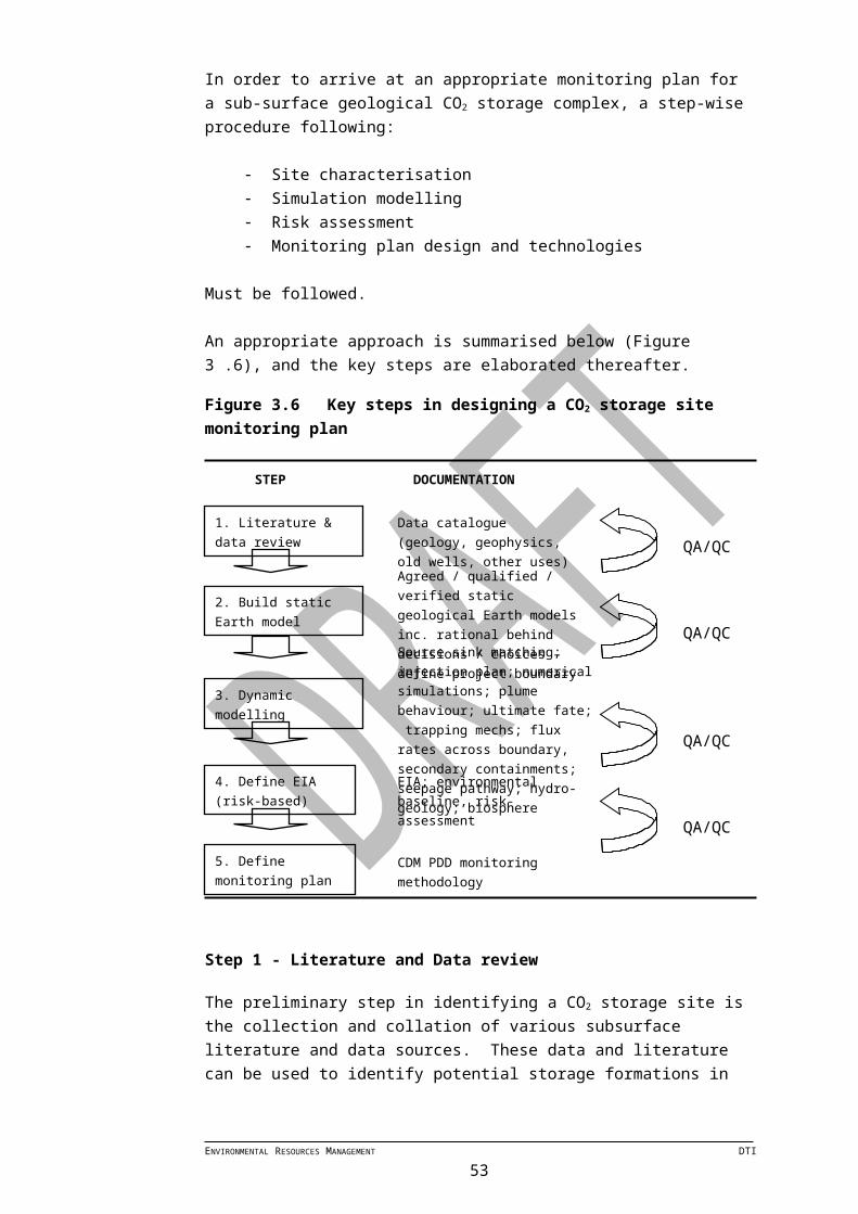
5 CONSIDERATIONS FOR EU ETS PHASE III
ENVIRONMENTAL RESOURCES MANAGEMENT DTI53
ERM has over 100 officesAcross the following countries worldwide
Argentina MalaysiaAustralia MexicoBelgium The NetherlandsBrazil New ZealandCanada PeruChile PolandChina PortugalColombia Puerto RicoEcuador RussiaFrance SingaporeGermany South AfricaHong Kong SpainHungary SwedenIndia TaiwanIndonesia ThailandIreland UKItaly United Arab EmiratesJapan USKazakhstan VietnamKorea Venezuela
ERM’s London Office
8 Cavendish SquareLondon W1G 0ERUK
Tel: +44 (0) 20 7465 7200Fax: +44 (0) 20 7465 7272
ERM consulting services worldwide www.erm.com