Norges Teknisk-Naturvitenskapelige Universitet The ... · Norges Teknisk-Naturvitenskapelige...
76
Report no: 2002:10 Norges Teknisk-Naturvitenskapelige Universitet The Norwegian University of Science and Technology Classification Open POSTADRESSE TELEFONER TELEFAX NTNU INSTITUTT FOR TERMISK ENERGI OG VANNKRAFT Kolbjørn Hejes vei 1A N-7491 Trondheim - NTNU Sentralbord NTNU: Instituttkontor: Vannkraftlaboratoriet: 73 59 40 00 73 59 27 00 73 59 38 57 Instituttkontor: Vannkraftlaboratoriet: 73 59 83 90 73 59 38 54 Title of report Date August 2002 Fuelsim - Average v1.1: A mass, volume and energy balance spreadsheet for continuous combustion applications No. of pages/appendixes 10/65 Author (s) Øyvind Skreiberg Project manager (sign.) Øyvind Skreiberg Division Faculty of Engineering Science and Technology Institute of Thermal Energy and Hydropower Project no. ISBN no. Price group Client/sponsor of project Nord-Interiør AS & The Research Council of Norway Clients's ref. Abstract Fuelsim - Average is a relatively simple, but useful, mass, volume and energy balance spreadsheet for continuous combustion applications, but can also be used for other thermal conversion processes where solid fuel is converted to a fuel gas mixture of O 2 , CO, NO, NO 2 , UHC (unburned hydrocarbons), SO 2 , N 2 O, H 2 , NH 3 , HCN, Tar, CO 2 , N 2 , Ar and H 2 O. The fuel can either be a solid fuel, a liquid fuel or a fuel gas, and the oxidant can either be ISO 2533 Standard air, with a user defined relative humidity, or a gas mixture of O 2 (the only oxidant), N 2 , CO 2 , Ar and H 2 O. Fuelsim - Average calculates emissions in various denominations based on the user input. However, also a separate emission conversion section is included, where emission values in various denominations can be inserted and converted between the various denominations. The corresponding emission levels in volume fractions can be inserted into the Fuelsim - Average main calculations and additional useful information are then calculated. Indexing terms: English Indexing Terms: Norwegian Group 1 Combustion Forbrenning Group 2 Fuels Brensler Selected by author Mass, volume and energy balances Masse-, volum- og energibalanser Emissions Utslipp Emission conversion Utslippskonvertering
Transcript of Norges Teknisk-Naturvitenskapelige Universitet The ... · Norges Teknisk-Naturvitenskapelige...
Report no:2002:10
Norges Teknisk-Naturvitenskapelige Universitet The Norwegian University of Science and Technology
ClassificationOpen
POSTADRESSE TELEFONER TELEFAX
NTNUINSTITUTT FOR TERMISK ENERGIOG VANNKRAFTKolbjørn Hejes vei 1AN-7491 Trondheim - NTNU
Sentralbord NTNU:Instituttkontor:Vannkraftlaboratoriet:
73 59 40 0073 59 27 0073 59 38 57
Instituttkontor:Vannkraftlaboratoriet:
73 59 83 9073 59 38 54
Title of report Date
August 2002Fuelsim - Average v1.1: A mass, volume and energy balance spreadsheetfor continuous combustion applications
No. of pages/appendixes
10/65Author (s)
Øyvind Skreiberg
Project manager (sign.)
Øyvind SkreibergDivision
Faculty of Engineering Science and TechnologyInstitute of Thermal Energy and Hydropower
Project no.
ISBN no. Price group
Client/sponsor of project
Nord-Interiør AS & The Research Council of Norway
Clients's ref.
Abstract
Fuelsim - Average is a relatively simple, but useful, mass, volume and energy balance spreadsheet for continuouscombustion applications, but can also be used for other thermal conversion processes where solid fuel is converted to afuel gas mixture of O2, CO, NO, NO2, UHC (unburned hydrocarbons), SO2, N2O, H2, NH3, HCN, Tar, CO2, N2, Ar and H2O.The fuel can either be a solid fuel, a liquid fuel or a fuel gas, and the oxidant can either be ISO 2533 Standard air, with auser defined relative humidity, or a gas mixture of O2 (the only oxidant), N2, CO2, Ar and H2O.
Fuelsim - Average calculates emissions in various denominations based on the user input. However, also a separateemission conversion section is included, where emission values in various denominations can be inserted and convertedbetween the various denominations. The corresponding emission levels in volume fractions can be inserted into theFuelsim - Average main calculations and additional useful information are then calculated.
Indexing terms: English Indexing Terms: Norwegian
Group 1Combustion Forbrenning
Group 2Fuels Brensler
Selectedby author
Mass, volume and energy balances Masse-, volum- og energibalanser
Emissions UtslippEmission conversion Utslippskonvertering
Fuelsim - Average v1.1:
A mass, volume and energy balance spreadsheet for continuous combustion applications
Øyvind Skreiberg
August 2002
PostDoc report – Part 2: Fuelsim - Average 2
Preface to version 1.1
Version 1.1 is an update to version 1.0 with respect to several aspects. Version 1.0 contained a couple of errorsand needs for clarification, which was corrected in a revision 1 (Fuelsim - Average_v1.0-r1.xls, of April 9,2002). See the revision history included in the spreadsheet for further details. However, this report was notupdated in the revision. In version 1.1 several additional updates have been included, mainly concerningimplementation of water injection, further examples, printout appearance, inclusion of high temperaturethermodynamic coefficients in the Gas conversion sheet and addition of the ISO 11042-1 sheet, comparing theISO 11042-1 1 standard and Fuelsim - Average. This report has therefore been updated to take into account allrelevant changes up to now. Again, see the revision history included in the spreadsheet for further details.
Preface to version 1.0
This PostDoc has been carried out as a part of a Norwegian industry project, Research and development of user-and environmentally friendly wood stoves and fireplaces, financially supported by the Research Council ofNorway. SINTEF Energy Research has been the research partner in the project, and the PostDoc has beenconcerned with one of three main subjects of research in the industry project. The PostDoc has been carried outas a 50% position over a three-year period.
The goal has been to study the potential of staged air combustion for NOx reduction in wood stoves andfireplaces, and to develop modelling tools for design of wood stoves and fireplaces. Initially, significant focuswas put on use of CFD, using CFX from AEA Technology. However, due to the complexity of fuel NOxchemical kinetics, the usefulness of using global, or even reduced, chemical kinetics for studies of NOxreduction by staged air combustion is highly questionable. Therefore, the modelling work has mainly beenconcerned with detailed studies of detailed chemical kinetics and modelling of staged air combustion in idealreactors, plug flow reactors and perfectly stirred reactors, representing two extremities of mixing conditions.Three different detailed chemical kinetics mechanisms have been used, compared and analysed in the modellingwork.
Two relatively simple, but useful, modelling tools have been developed as tools for design of wood stoves andfireplaces. Fuelsim - Average is a general mass, volume and energy balance spreadsheet for continuouscombustion applications, for adiabatic conditions. This spreadsheet has been made publicly available at theInternet homepage of IEA Task 32 - Biomass Combustion and Co-firing. Fuelsim - Transient is a transientversion of Fuelsim - Average, designed for batch combustion of wood in wood stoves and fireplaces. It includesa number of transient models and also heat transfer calculations.
The author would like to thank our industry partner, Nord-Interiør AS, and the Research Council of Norway forfinancial support. Project leader and Research Scientist Edvard Karlsvik at SINTEF Energy Research andProfessor Johan E. Hustad are acknowledged for their support through these three years. Dr. Pia Kilpinen,Vesna Barisic and Edgardo Coda Zabetta at Åbo Akademi in Finland are acknowledged for their contribution tothe NOx part of this work trough collaboration, as is Dr. Peter Glarborg at the Technical University of Denmark.Finally, the Nordic Energy Research Program is acknowledged for their indirect support through the NordicSenior Research Scientist position of the author.
1 ISO 11042-1. Gas turbines - Exhaust gas emission - Part 1: Measurement and evaluation, 1996.
PostDoc report – Part 2: Fuelsim - Average 3
Table of Contents
Preface to version 1.1 2
Preface to version 1.0 2
List of figures 4
1. Summary 5
2. Introduction 6
3. Description of Fuelsim - Average 7
3.1 Introduction 7
3.2 Methods 8
3.3 Areas of use 8
3.4 ISO 2533 Standard dry air composition 9
3.5 Relative air humidity 10
Appendix 1 - Mass, volume and energy balance equations and emission calculations
Appendix 2 - Fuelsim - Average introduction
Appendix 3 - Fuelsim - Average documentation
Appendix 4 - Fuelsim - Average examples
Appendix 5 - Fuelsim - Average exercise
Appendix 6 - Fuelsim - Average versus ISO 11042-1

PostDoc report – Part 2: Fuelsim - Average 4
List of figures
Figure 1 Conservation of mass and energy - schematic overview......................................................................8
Figure 2 Main input, and output examples. ........................................................................................................8
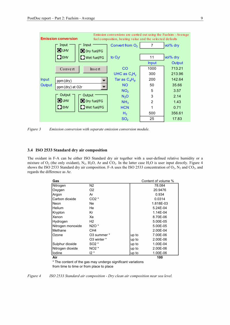
Figure 3 Emission conversion with separate emission conversion module........................................................9
Figure 4 ISO 2533 Standard air composition - Dry clean air composition near sea level. ...............................9
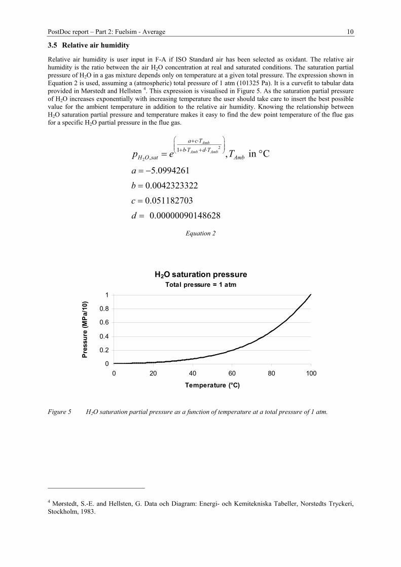
Figure 5 H2O saturation partial pressure as a function of temperature at a total pressure of 1 atm. .............10
PostDoc report – Part 2: Fuelsim - Average 5
1. Summary
Fuelsim - Average is a relatively simple, but useful, mass, volume and energy balance spreadsheet forcontinuous combustion applications, but can also be used for other thermal conversion processes where solidfuel is converted to a fuel gas mixture of O2, CO, NO, NO2, UHC (unburned hydrocarbons), SO2, N2O, H2, NH3,HCN, Tar, CO2, N2, Ar and H2O. The fuel can either be a solid fuel, a liquid fuel or a fuel gas, and the oxidantcan either be ISO 2533 2 Standard air, with a user defined relative humidity, or a gas mixture of O2 (the onlyoxidant), N2, CO2, Ar and H2O.
Fuelsim - Average calculates emissions in various denominations based on the user input. However, also aseparate emission conversion section is included, where emission values in various denominations can beinserted and converted between the various denominations. The corresponding emission levels in volumefractions can be inserted into the Fuelsim - Average main calculations and additional useful information are thencalculated.
Sammendrag (Summary in Norwegian)
Fuelsim - Average er et relativt enkelt masse-, volum- og energibalanse regneark for kontinuerligeforbrenningsprosesser, men kan også brukes for andre termiske konverteringsprosesser hvor faste brenslerkonverteres til en brenselgass av O2, CO, NO, NO2, UHC (uforbrente hydrokarboner), SO2, N2O, H2, NH3,HCN, Tjære, CO2, N2, Ar og H2O. Brenselet kan enten være et fast brensel, et flytende brensel eller enbrenselgass, og oksidanten kan enten være ISO 2533 2 Standard luft, med en brukerdefinert relativ luftfuktighet,eller en blanding av O2 (eneste oksidant), N2, CO2, Ar og H2O.
Fuelsim - Average beregner utslipp i ulike benevninger basert på brukerens input. Også en separatutslippskonverteringsdel er inkludert, hvor utslipp i flere forskjellige benevninger kan settes inn og konverterestil andre benevninger. De korresponderende utslippene i volumfraksjoner kan settes inn i Fuelsim - Average ogytterligere informasjon vil bli beregnet.
2 ISO 2533. Standard Atmosphere, 1975.
PostDoc report – Part 2: Fuelsim - Average 6
2. Introduction
Mass, volume and energy balances form the basis for any thermal conversion process where a fuel (solid, liquidor gas) is converted to products. Combustion processes are highly complex conversion processes where a largenumber of elementary reactions influence the conversion of the fuel to products, in addition to a number ofoperational parameters. To be able to adequately model the conversion process and the formation of emissionssuch as NOx, detailed chemical kinetics should be applied in combination with Computational Fluid Dynamics(CFD). Today, this is possible but very time consuming, and still the degree of uncertainty in for example NOxemission prediction is considerable. However, to design combustion applications such as wood stoves andfireplaces a global combustion reaction is quite sufficient as a first engineering approach. From a globalcombustion equation, the necessary information regarding global mass, volume and energy flows can be derivedrelatively easily, as well as the concentration of major species. To study transient effects in batch combustionapplications, transient models may be used in combinations with the formulas shown in Appendix 1. Transientmodelling of batch combustion processes is the subject of Part 3 of this PostDoc work.
If information regarding minor species emissions is available, the global combustion equation can easily beextended to include also these species. This makes it possible to carry out a number of calculations for the minorspecies, including emission conversion to various denomination, conversion factors for each species, etc.
Conversion of emissions to other denominations is in principle very simple. However, in practise it is not alwaysthat simple. Formulas and procedures for emission conversion between the most common denominations areshown in Appendix 1. These formulas and procedures are based directly on the combustion equation used inFuelsim - Average and do not include the simplifications usually applied in many other formulas for emissionconversion. These formulas and procedures are applied in the separate emission conversion section in Fuelsim -Average. The accuracy of the emission conversion process is limited by the amount of information stated inaddition to the specific emission level in some denomination.
Appendix 2 gives a short introduction to Fuelsim - Average while Appendix 3 includes description anddocumentation of the spreadsheet, in addition to the formulas included in Appendix 1. Examples of use areincluded in Appendix 4, while an exercise is included in Appendix 5. Finally, Appendix 6 compares Fuelsim -Average versus ISO 11042-1.
PostDoc report – Part 2: Fuelsim - Average 7
3. Description of Fuelsim - Average
3.1 Introduction
Fuelsim - Average is a relatively simple, but useful, mass, volume and energy balance spreadsheet forcontinuous combustion applications, but can also be used for other thermal conversion processes where solidfuel is converted to a fuel gas mixture of O2, CO, NO, NO2, UHC (unburned hydrocarbons), SO2, N2O, H2, NH3,HCN, Tar, CO2, N2, Ar and H2O.
The fuel can either be a solid fuel, a liquid fuel or a fuel gas, and the oxidant can either be ISO 2533 Standardair, with a user defined relative humidity, or a gas mixture of O2 (the only oxidant), N2, CO2, Ar and H2O.
Preheating, relative to an ambient temperature, of solid or liquid fuel (including moisture content), fuel gas,water for water injection and oxidant (separated into primary and secondary air) is possible. The temperature ofthe products is calculated assuming adiabatic conditions (no heat loss).
Fuelsim - Average uses thermodynamic data on CHEMKIN 3 format for all gas species and also liquid water,while the specific heat capacity of a solid or liquid fuel is user defined. The heating value of a fuel gas iscalculated directly from the thermodynamic data, while the heating value of a solid fuel is estimated from theelemental composition using an empirical expression. However, the heating value may also be insertedmanually. The heating value of a liquid fuel should be inserted manually.
The user may add new fuel gas species, including accompanying thermodynamic data on CHEMKIN format.
Thermal efficiency (using a user defined chimney inlet temperature), combustion efficiency and total efficiencyare calculated, together with further useful mass, volume and energy balance output.
Fuelsim - Average calculates emissions in various denominations based on the user input. However, also aseparate emission conversion section is included, where emission values in various denominations can beinserted and converted between the various denominations. The corresponding emission levels in volumefractions can be inserted into the Fuelsim - Average main calculations and additional useful information are thencalculated.
The emission conversion procedure is based directly on the combustion equation, no simplified expressions areapplied. When converting emission levels between different oxygen concentrations, the defined oxidant is addedto, or removed from, the given flue gas composition until the calculated oxygen concentration equals thereference oxygen concentration.
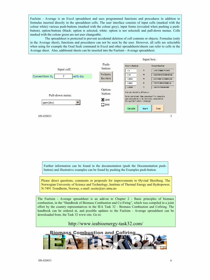
Fuelsim - Average is an Excel spreadsheet and uses programmed functions and procedures in addition toformulas inserted directly in the spreadsheet cells. The user interface consists of input cells (marked with thecolour white) various push-buttons (marked with the colour grey), input forms (revealed when pushing a push-button), option-buttons (black: option is selected, white: option is not selected) and pull-down menus. Cellsmarked with the colour green are not user changeable.
The spreadsheet is protected to prevent accidental deletion of cell contents or objects. Formulas (only in theAverage sheet), functions and procedures can not be seen by the user. However, all cells are selectable whenusing for example the Goal Seek command in Excel and other spreadsheets/sheets can refer to cells in theAverage sheet. Also, additional sheets can be inserted into the Fuelsim - Average spreadsheet.
The main purpose of Fuelsim - Average is to provide the user with information regarding mass, volume andenergy flows in continuous combustion applications, depending on a number of inputs described in more detailin the appendixes. The goal here is only to give a brief introduction to Fuelsim - Average and the reader isreferred to the appendixes for further details.
3 CHE-036-1, CHEMKIN Collection Release 3.6, A Software Package for the Analysis of Gas-Phase Chemicaland Plasma Kinetics, September 2000
PostDoc report – Part 2: Fuelsim - Average 8
3.2 Methods
The global combustion equation used in Fuelsim - Average (F-A) is shown in Equation 1. By balancing thisequation mass and volume flow calculations can be carried out. By also introducing thermodynamic data for thereactants and products, energy calculations can be carried out in addition. Additionally, solid or liquid fuels maycontain water in F-A. Further formulas are given in Appendix 1.
( ) ( )2 2 2 2
2
2 2 2 2 2
2 2 2 3 2, 2
x y
xt yt Air Air
C H O N S O N Ar CO H OFuel AirO
CO H O O N CO NO NO C H
SO N O H NH HCN C H Ar CO H O
za Y Y Y Y Y Y Y Y Y YY
b c d e f g h i
j k l m n o p q r
⋅ + + + + + ⋅ + + + +
⇒ + + + + + + +
+ + + + + + + + +
Equation 1
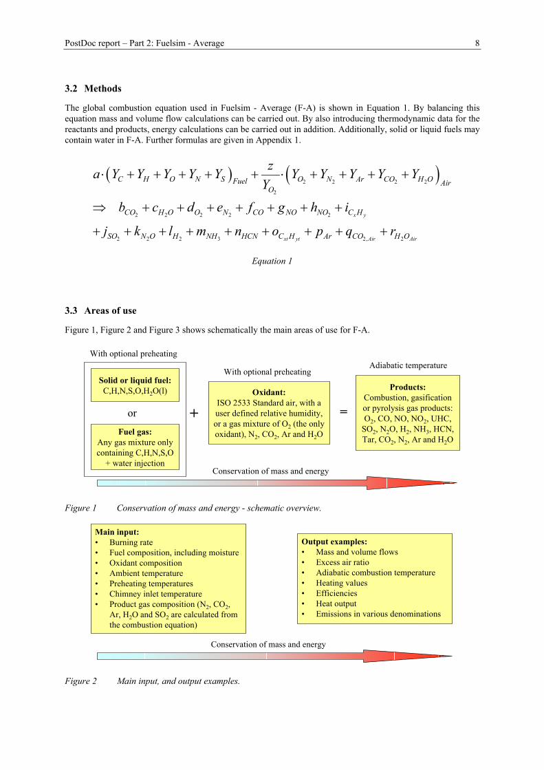
3.3 Areas of use
Figure 1, Figure 2 and Figure 3 shows schematically the main areas of use for F-A.
Products:Combustion, gasificationor pyrolysis gas products:O2, CO, NO, NO2, UHC,
SO2, N2O, H2, NH3, HCN,Tar, CO2, N2, Ar and H2O
Solid or liquid fuel:C,H,N,S,O,H2O(l)
Fuel gas:Any gas mixture onlycontaining C,H,N,S,O
+ water injection
Oxidant:ISO 2533 Standard air, with auser defined relative humidity,or a gas mixture of O2 (the onlyoxidant), N2, CO2, Ar and H2O
or + =
Conservation of mass and energy
With optional preheatingAdiabatic temperature
With optional preheating
Figure 1 Conservation of mass and energy - schematic overview.
Conservation of mass and energy
Main input:• Burning rate• Fuel composition, including moisture• Oxidant composition• Ambient temperature• Preheating temperatures• Chimney inlet temperature• Product gas composition (N2, CO2,
Ar, H2O and SO2 are calculated fromthe combustion equation)
Output examples:• Mass and volume flows• Excess air ratio• Adiabatic combustion temperature• Heating values• Efficiencies• Heat output• Emissions in various denominations
Figure 2 Main input, and output examples.
PostDoc report – Part 2: Fuelsim - Average 9
Emission conversion
Convert from O2 7 vol% dry0
to O2r 11 vol% dryInput Output
CO 1000 713.21UHC as CxHy 300 213.96
Input Tar as CxtHyt 200 142.64Output NO 50 35.66
NO2 5 3.57N2O 3 2.14NH3 2 1.43HCN 1 0.71
H2 500 356.61SO2 25 17.83
Emission conversions are carried out using the Fuelsim - Averagefuel composition, heating value and the se lected defaults
ppm (dry)
ppm (dry) at O2r
Output
UHV
EHV
Output
Dry fuel/FG
Wet fuel/FG
Input
UHV
EHV
Input
Dry fuel/FG
Wet fuel/FG
Conve rt Ins e rt
Figure 3 Emission conversion with separate emission conversion module.
3.4 ISO 2533 Standard dry air composition
The oxidant in F-A can be either ISO Standard dry air together with a user-defined relative humidity or amixture of O2 (the only oxidant), N2, H2O, Ar and CO2. In the latter case H2O is user input directly. Figure 4shows the ISO 2533 Standard dry air composition. F-A uses the ISO 2533 concentration of O2, N2 and CO2, andregards the difference as Ar.
Gas Content of volume %Nitrogen N2 78.084Oxygen O2 20.9476Argon Ar 0.934Carbon dioxide CO2 * 0.0314Neon Ne 1.818E-03Helium He 5.24E-04Krypton Kr 1.14E-04Xenon Xe 8.70E-06Hydrogen H2 5.00E-05Nitrogen monoxide N2O * 5.00E-05Methane CH4 2.00E-04Ozone O3 summer * up to 7.00E-06
O3 winter * up to 2.00E-06Sulphur dioxide SO2 * up to 1.00E-04Nitrogen dioxide NO2 * up to 2.00E-06Iodine I2 * up to 1.00E-06Air 100* The content of the gas may undergo significant variationsfrom time to time or from place to place
Figure 4 ISO 2533 Standard air composition - Dry clean air composition near sea level.
PostDoc report – Part 2: Fuelsim - Average 10
3.5 Relative air humidity
Relative air humidity is user input in F-A if ISO Standard air has been selected as oxidant. The relative airhumidity is the ratio between the air H2O concentration at real and saturated conditions. The saturation partialpressure of H2O in a gas mixture depends only on temperature at a given total pressure. The expression shown inEquation 2 is used, assuming a (atmospheric) total pressure of 1 atm (101325 Pa). It is a curvefit to tabular dataprovided in Mørstedt and Hellsten 4. This expression is visualised in Figure 5. As the saturation partial pressureof H2O increases exponentially with increasing temperature the user should take care to insert the best possiblevalue for the ambient temperature in addition to the relative air humidity. Knowing the relationship betweenH2O saturation partial pressure and temperature makes it easy to find the dew point temperature of the flue gasfor a specific H2O partial pressure in the flue gas.
2
2
1,
5.09942610.00423233220.051182703 0.00000090148628
, in CAmb
Amb Amb
a c Tb T d T
H O sat Amb
abcd
p e T + ⋅ + ⋅ + ⋅
= −
=
=
=
= °
Equation 2
H2O saturation pressureTotal pressure = 1 atm
0
0.2
0.4
0.6
0.8
1
0 20 40 60 80 100
Temperature (°C)
Pres
sure
(MPa
/10)
Figure 5 H2O saturation partial pressure as a function of temperature at a total pressure of 1 atm.
4 Mørstedt, S.-E. and Hellsten, G. Data och Diagram: Energi- och Kemitekniska Tabeller, Norstedts Tryckeri,Stockholm, 1983.
Appendix 1
Mass, volume and energy balance equations and emission calculations
Øyvind Skreiberg
August 2002
Mass, volume and energy balance equations and emission calculations
1
Mass, volume and energy balance equations and emission calculations
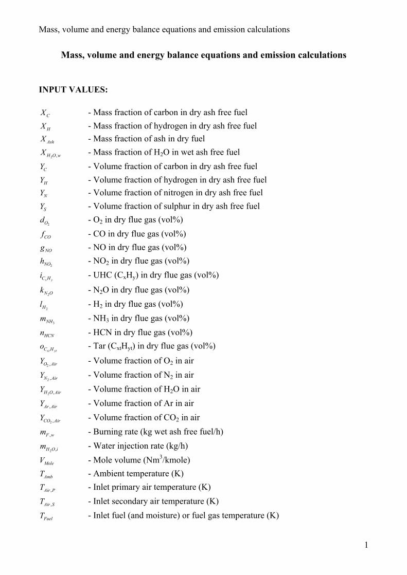
INPUT VALUES:
CX - Mass fraction of carbon in dry ash free fuel
HX - Mass fraction of hydrogen in dry ash free fuel
AshX - Mass fraction of ash in dry fuel
2 ,H O wX - Mass fraction of H2O in wet ash free fuel
CY - Volume fraction of carbon in dry ash free fuel
HY - Volume fraction of hydrogen in dry ash free fuel
NY - Volume fraction of nitrogen in dry ash free fuel
SY - Volume fraction of sulphur in dry ash free fuel
2Od - O2 in dry flue gas (vol%)
COf - CO in dry flue gas (vol%)
NOg - NO in dry flue gas (vol%)
2NOh - NO2 in dry flue gas (vol%)
x yC Hi - UHC (CxHy) in dry flue gas (vol%)
2N Ok - N2O in dry flue gas (vol%)
2Hl - H2 in dry flue gas (vol%)
3NHm - NH3 in dry flue gas (vol%)
HCNn - HCN in dry flue gas (vol%)
xt ytC Ho - Tar (CxtHyt) in dry flue gas (vol%)
2 ,O AirY - Volume fraction of O2 in air
2 ,N AirY - Volume fraction of N2 in air
2 ,H O AirY - Volume fraction of H2O in air
,Ar AirY - Volume fraction of Ar in air
2 ,CO AirY - Volume fraction of CO2 in air
,F wm - Burning rate (kg wet ash free fuel/h)
2 ,H O im - Water injection rate (kg/h)
MoleV - Mole volume (Nm3/kmole)
AmbT - Ambient temperature (K)
,Air PT - Inlet primary air temperature (K)
,Air ST - Inlet secondary air temperature (K)
FuelT - Inlet fuel (and moisture) or fuel gas temperature (K)
Mass, volume and energy balance equations and emission calculations
2
2 ,H O iT - Water for water injection temperature (K)
ChT - Chimney inlet temperature (K)
FuelCp - Specific heat capacity of inlet fuel (kJ/kgK)
AirP - Weight fraction primary air of total air
CONSTANTS:
CM - Mole weight of carbon (kg/kmole)
HM - Mole weight of hydrogen (kg/kmole)
NM - Mole weight of nitrogen (kg/kmole)
SM - Mole weight of sulphur (kg/kmole)
OM - Mole weight of oxygen (kg/kmole)
ArM - Mole weight of argon (kg/kmole)
Mole weights of flue gas species are calculated from the elementary mole weights

Mass, volume and energy balance equations and emission calculations
3
Combustion equation:
( ) ( )2 2 2 2
2
2 2 2 2 2
2 2 2 3 2, 2
x y
xt yt Air Air
C H O N S O N Ar CO H OFuel AirO
CO H O O N CO NO NO C H
SO N O H NH HCN C H Ar CO H O
za Y Y Y Y Y Y Y Y Y YY
b c d e f g h i
j k l m n o p q r
⋅ + + + + + ⋅ + + + +
⇒ + + + + + + +
+ + + + + + + + +
Eq. 1
Elemental balances:
2
2
,
,
6 9100 1 42 8 2
2 2 28
NC S
N Air N C S
O Air
YceX ceXceX ceX Y YceXz Y Y Y Y ceX
Y ceX
− + + − ⋅ + + =
+ ⋅ + ⋅+ +
Eq. 2
2 + 98
z ceXaceX
⋅= Eq. 3
4Cb a Y ceX= ⋅ − Eq. 4
52
Ha Y ceXc ⋅ −= Eq. 5
Sj a Y= ⋅ Eq. 6
2
,
,
Ar Air
O Air
Yp z
Y= ⋅ Eq. 7
2
2
,
,
CO Air
O Air
Yq z
Y= ⋅ Eq. 8
2
2
,
,
H O Air
O Air
Yr z
Y= ⋅ Eq. 9
Dry flue gas balance:100 1 2e ceX b z ceX j= − − − ⋅ − Eq. 10
where:1ceX d f g h i k l m n o= + + + + + + + + + Eq. 11
2
2
Ar,Air CO ,Air
O ,Air
Y +Y2
YceX = Eq. 12
Mass, volume and energy balance equations and emission calculations
4
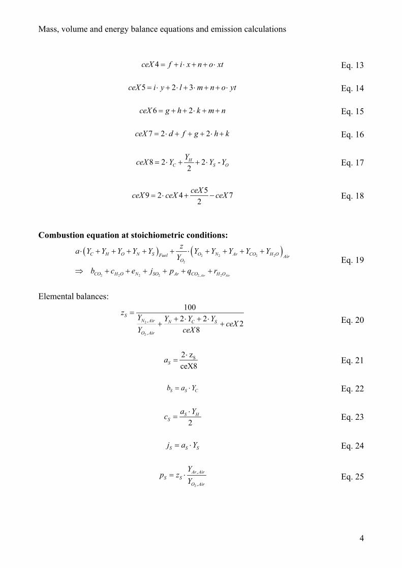
4ceX f i x n o xt= + ⋅ + + ⋅ Eq. 13
5 2 3ceX i y l m n o yt= ⋅ + ⋅ + ⋅ + + ⋅ Eq. 14
6 2ceX g h k m n= + + ⋅ + + Eq. 15
7 2 2ceX d f g h k= ⋅ + + + ⋅ + Eq. 16
8 2 2 -2H
C S OYceX Y Y Y= ⋅ + + ⋅ Eq. 17
59 2 4 72
ceXceX ceX ceX= ⋅ + − Eq. 18
Combustion equation at stoichiometric conditions:
( ) ( )2 2 2 2
2
2 2 2 2 2, 2Air Air
C H O N S O N Ar CO H OFuel AirO
CO H O N SO Ar CO H O
za Y Y Y Y Y Y Y Y Y YY
b c e j p q r
⋅ + + + + + ⋅ + + + +
⇒ + + + + + +Eq. 19
Elemental balances:
2
2
,
,
1002 2 2
8
SN Air N C S
O Air
z Y Y Y Y ceXY ceX
=+ ⋅ + ⋅
+ + Eq. 20
S2 zceX8Sa⋅
= Eq. 21
S S Cb a Y= ⋅ Eq. 22
2S H
Sa Yc ⋅
= Eq. 23
S S Sj a Y= ⋅ Eq. 24
2
,
,
Ar AirS S
O Air
Yp z
Y= ⋅ Eq. 25
Mass, volume and energy balance equations and emission calculations
5
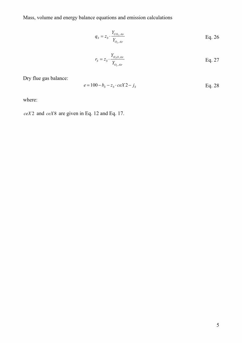
2
2
,
,
CO AirS S
O Air
Yq z
Y= ⋅ Eq. 26
2
2
,
,
H O AirS S
O Air
Yr z
Y= ⋅ Eq. 27
Dry flue gas balance:100 2S S Se b z ceX j= − − ⋅ − Eq. 28
where:
2ceX and 8ceX are given in Eq. 12 and Eq. 17.
Mass, volume and energy balance equations and emission calculations
6
MASS AND VOLUME CALCULATIONS:
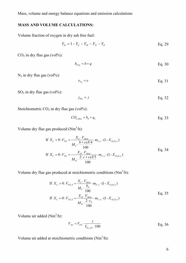
Volume fraction of oxygen in dry ash free fuel:
SNHCO YYYYY −−−−= 1 Eq. 29
CO2 in dry flue gas (vol%):
2COb b q= + Eq. 30
N2 in dry flue gas (vol%):2N
e e= Eq. 31
SO2 in dry flue gas (vol%):2SOj j= Eq. 32
Stoichiometric CO2 in dry flue gas (vol%):
2,Max S sCO b q= + Eq. 33
Volume dry flue gas produced (Nm3/h):
2
2
, ,
, ,
If 0 : (1- )4100
If 0 : (1- )2 5100
C MoleC FG F w H O w
C
H MoleC FG F w H O w
H
X VX V m Xb ceXM
X VX V m Xc ceXM
⋅> = ⋅ ⋅
+⋅
⋅= = ⋅ ⋅
⋅ +⋅
Eq. 34
Volume dry flue gas produced at stoichiometric conditions (Nm3/h):
2
2
, , ,
, , ,
If 0 : (1- )
100
If 0 : (1- )2100
C MoleC FG S F w H O w
SC
H MoleC FG S F w H O w
SH
X VX V m XbM
X VX V m XcM
⋅> = ⋅ ⋅
⋅
⋅= = ⋅ ⋅
⋅⋅
Eq. 35
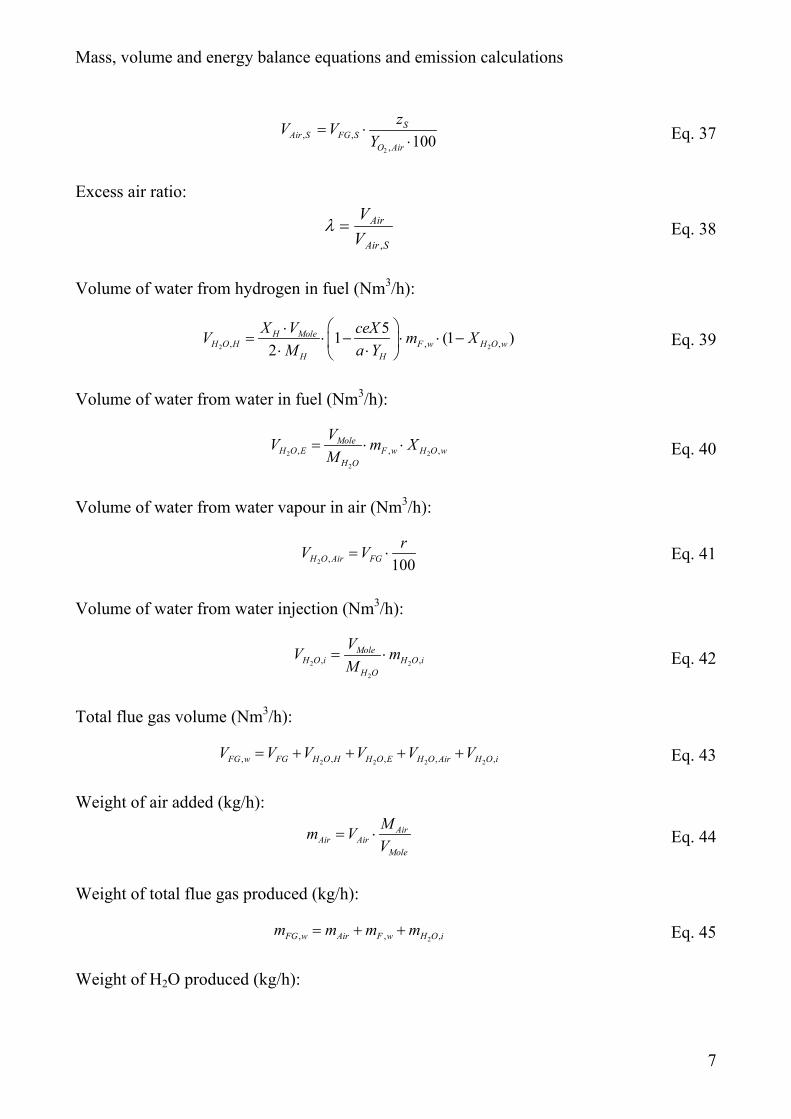
Volume air added (Nm3/h):
2 , 100Air FGO Air
zV VY
= ⋅⋅ Eq. 36
Volume air added at stoichiometric conditions (Nm3/h):
Mass, volume and energy balance equations and emission calculations
7
2
, ,, 100
SAir S FG S
O Air
zV VY
= ⋅⋅ Eq. 37
Excess air ratio:
SAir
Air
VV
,
=λ Eq. 38
Volume of water from hydrogen in fuel (Nm3/h):
2 2, , ,51 (1 )
2H Mole
H O H F w H O wH H
X V ceXV m XM a Y
⋅= ⋅ − ⋅ ⋅ − ⋅ ⋅
Eq. 39
Volume of water from water in fuel (Nm3/h):
2 2
2
, , ,Mole
H O E F w H O wH O
VV m XM
= ⋅ ⋅ Eq. 40
Volume of water from water vapour in air (Nm3/h):
2 , 100H O Air FGrV V= ⋅ Eq. 41
Volume of water from water injection (Nm3/h):
2 2
2
, ,Mole
H O i H O iH O
VV mM
= ⋅ Eq. 42
Total flue gas volume (Nm3/h):
2 2 2 2, , , , ,FG w FG H O H H O E H O Air H O iV V V V V V= + + + + Eq. 43
Weight of air added (kg/h):Air
Air AirMole
Mm VV
= ⋅ Eq. 44
Weight of total flue gas produced (kg/h):
2, , ,FG w Air F w H O im m m m= + + Eq. 45
Weight of H2O produced (kg/h):
Mass, volume and energy balance equations and emission calculations
8
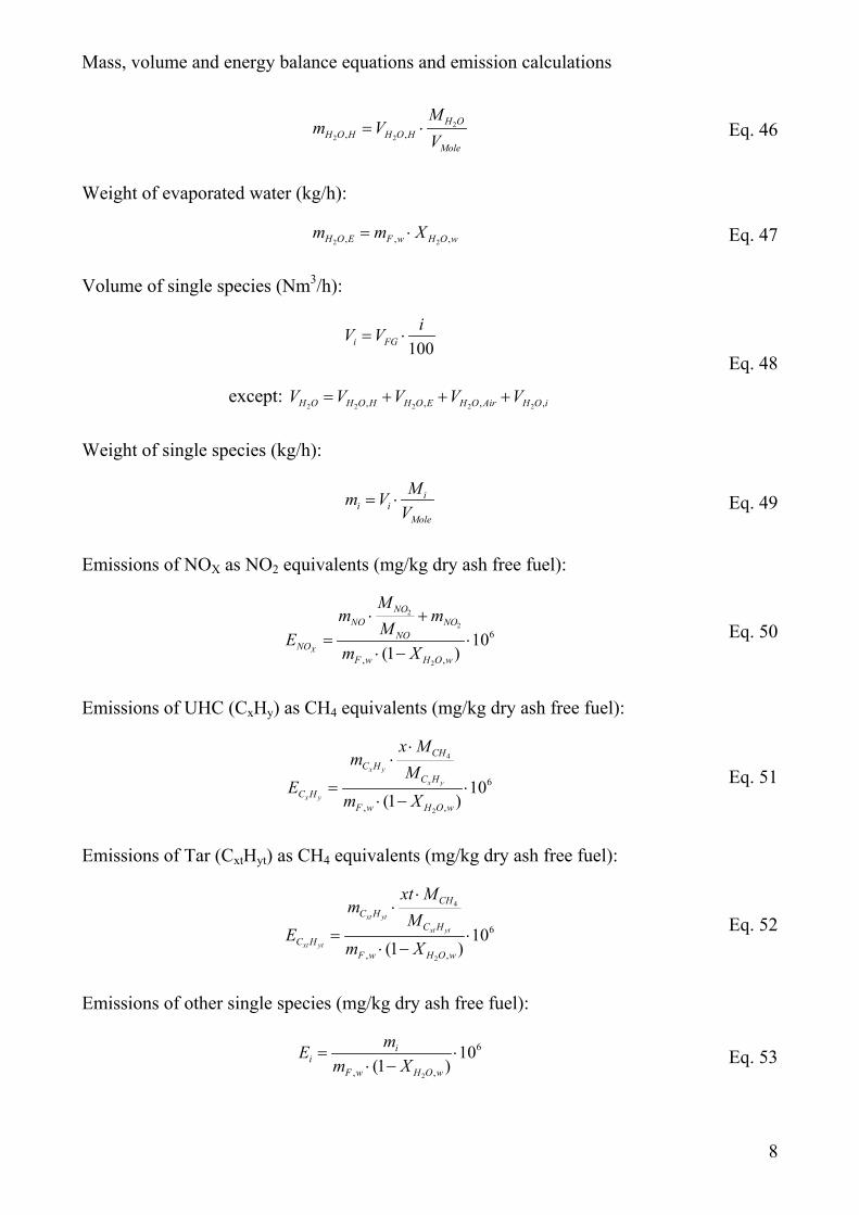
2
2 2, ,H O
H O H H O HMole
Mm V
V= ⋅ Eq. 46
Weight of evaporated water (kg/h):
2 2, , ,H O E F w H O wm m X= ⋅ Eq. 47
Volume of single species (Nm3/h):
100i FGiV V= ⋅
except: 2 2 2 2 2, , , ,H O H O H H O E H O Air H O iV V V V V= + + +
Eq. 48
Weight of single species (kg/h):
ii i
Mole
Mm VV
= ⋅ Eq. 49
Emissions of NOX as NO2 equivalents (mg/kg dry ash free fuel):
2
2
2
6
, ,
10(1 )X
NONO NO
NONO
F w H O w
Mm m
MEm X
⋅ += ⋅
⋅ −Eq. 50
Emissions of UHC (CxHy) as CH4 equivalents (mg/kg dry ash free fuel):
4
2
6
, ,
10(1 )
x y
x y
x y
CHC H
C HC H
F w H O w
x Mm
ME
m X
⋅⋅
= ⋅⋅ −
Eq. 51
Emissions of Tar (CxtHyt) as CH4 equivalents (mg/kg dry ash free fuel):
4
2
6
, ,
10(1 )
xt yt
xt yt
xt yt
CHC H
C HC H
F w H O w
xt Mm
ME
m X
⋅⋅
= ⋅⋅ −
Eq. 52
Emissions of other single species (mg/kg dry ash free fuel):
2
6
, ,
10(1 )
ii
F w H O w
mEm X
= ⋅⋅ − Eq. 53
Mass, volume and energy balance equations and emission calculations
9
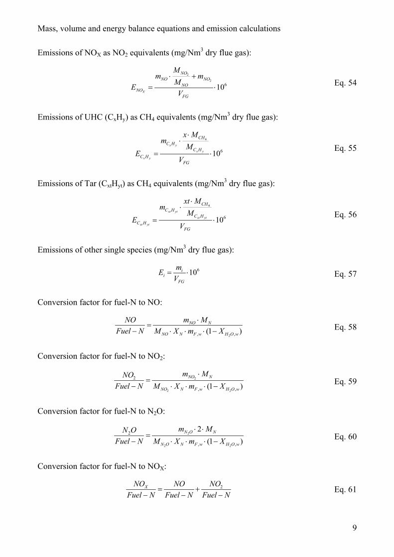
Emissions of NOX as NO2 equivalents (mg/Nm3 dry flue gas):
2
2610
X
NONO NO
NONO
FG
Mm m
MEV
⋅ += ⋅ Eq. 54
Emissions of UHC (CxHy) as CH4 equivalents (mg/Nm3 dry flue gas):
4
610x y
x y
x y
CHC H
C HC H
FG
x Mm
ME
V
⋅⋅
= ⋅Eq. 55
Emissions of Tar (CxtHyt) as CH4 equivalents (mg/Nm3 dry flue gas):
4
610xt yt
xt yt
xt yt
CHC H
C HC H
FG
xt Mm
ME
V
⋅⋅
= ⋅Eq. 56
Emissions of other single species (mg/Nm3 dry flue gas):
610ii
FG
mEV
= ⋅ Eq. 57
Conversion factor for fuel-N to NO:
2, ,(1 )NO N
NO N F w H O w
m MNOFuel N M X m X
⋅=
− ⋅ ⋅ ⋅ − Eq. 58
Conversion factor for fuel-N to NO2:
2
2 2
2
, ,(1 )NO N
NO N F w H O w
m MNOFuel N M X m X
⋅=
− ⋅ ⋅ ⋅ − Eq. 59
Conversion factor for fuel-N to N2O:
2
2 2
2
, ,
2(1 )
N O N
N O N F w H O w
m MN OFuel N M X m X
⋅ ⋅=
− ⋅ ⋅ ⋅ − Eq. 60
Conversion factor for fuel-N to NOX:
2XNO NO NOFuel N Fuel N Fuel N
= +− − −
Eq. 61
Mass, volume and energy balance equations and emission calculations
10
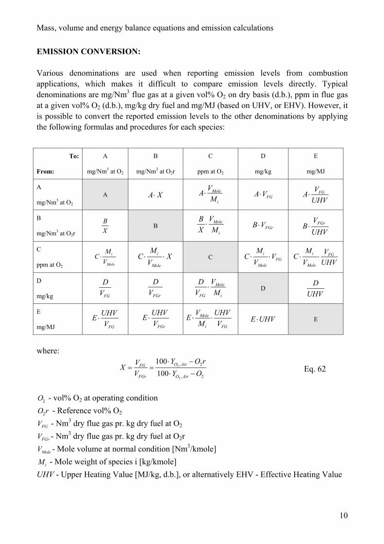
EMISSION CONVERSION:
Various denominations are used when reporting emission levels from combustionapplications, which makes it difficult to compare emission levels directly. Typicaldenominations are mg/Nm3 flue gas at a given vol% O2 on dry basis (d.b.), ppm in flue gasat a given vol% O2 (d.b.), mg/kg dry fuel and mg/MJ (based on UHV, or EHV). However, itis possible to convert the reported emission levels to the other denominations by applyingthe following formulas and procedures for each species:
To:
From:
A
mg/Nm3 at O2
B
mg/Nm3 at O2r
C
ppm at O2
D
mg/kg
E
mg/MJ
A
mg/Nm3 at O2
A A X⋅ Mole
i
VAM
⋅ FGA V⋅ FGVAUHV⋅
B
mg/Nm3 at O2r
BX
BMole
i
VBX M⋅ FGrB V⋅ FGrV
BUHV⋅
C
ppm at O2
i
Mole
MCV⋅ i
Mole
MC XV⋅ ⋅ C
iFG
Mole
MC VV⋅ ⋅ i FG
Mole
M VCV UHV⋅ ⋅
D
mg/kg FG
DV FGr
DV
Mole
FG i
VDV M
⋅ DD
UHV
E
mg/MJ FG
UHVEV
⋅FGr
UHVEV
⋅ Mole
i FG
V UHVEM V
⋅ ⋅ E UHV⋅ E
where:2
2
, 2
, 2
100100
O AirFG
FGr O Air
Y O rVXV Y O
⋅ −= =
⋅ − Eq. 62
2O - vol% O2 at operating condition
2O r - Reference vol% O2
FGV - Nm3 dry flue gas pr. kg dry fuel at O2
FGrV - Nm3 dry flue gas pr. kg dry fuel at O2r
MoleV - Mole volume at normal condition [Nm3/kmole]
iM - Mole weight of species i [kg/kmole]UHV - Upper Heating Value [MJ/kg, d.b.], or alternatively EHV - Effective Heating Value
Mass, volume and energy balance equations and emission calculations
11
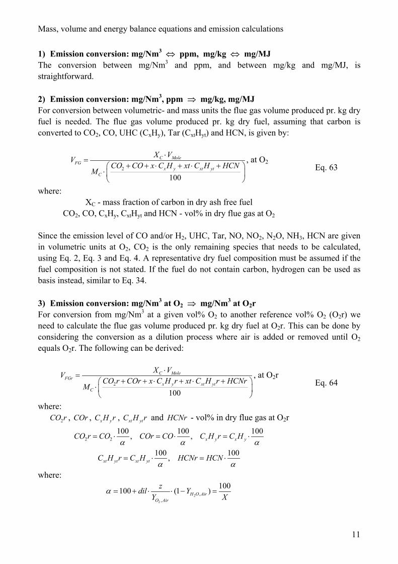
1) Emission conversion: mg/Nm3 ⇔ ppm, mg/kg ⇔ mg/MJThe conversion between mg/Nm3 and ppm, and between mg/kg and mg/MJ, isstraightforward.
2) Emission conversion: mg/Nm3, ppm ⇒ mg/kg, mg/MJFor conversion between volumetric- and mass units the flue gas volume produced pr. kg dryfuel is needed. The flue gas volume produced pr. kg dry fuel, assuming that carbon isconverted to CO2, CO, UHC (CxHy), Tar (CxtHyt) and HCN, is given by:
2
100
C MoleFG
x y xt ytC
X VVCO CO x C H xt C H HCN
M
⋅=
+ + ⋅ + ⋅ + ⋅
, at O2Eq. 63
where:XC - mass fraction of carbon in dry ash free fuel
CO2, CO, CxHy, CxtHyt and HCN - vol% in dry flue gas at O2
Since the emission level of CO and/or H2, UHC, Tar, NO, NO2, N2O, NH3, HCN are givenin volumetric units at O2, CO2 is the only remaining species that needs to be calculated,using Eq. 2, Eq. 3 and Eq. 4. A representative dry fuel composition must be assumed if thefuel composition is not stated. If the fuel do not contain carbon, hydrogen can be used asbasis instead, similar to Eq. 34.
3) Emission conversion: mg/Nm3 at O2 ⇒ mg/Nm3 at O2rFor conversion from mg/Nm3 at a given vol% O2 to another reference vol% O2 (O2r) weneed to calculate the flue gas volume produced pr. kg dry fuel at O2r. This can be done byconsidering the conversion as a dilution process where air is added or removed until O2
equals O2r. The following can be derived:
2
100
C MoleFGr
x y xt ytC
X VVCO r COr x C H r xt C H r HCNr
M
⋅=
+ + ⋅ + ⋅ + ⋅
, at O2rEq. 64
where:2CO r , COr , x yC H r , xt ytC H r and HCNr - vol% in dry flue gas at O2r
2 2100 100 100, , x y x yCO r CO COr CO C H r C Hα α α
= ⋅ = ⋅ = ⋅
100 100,xt yt xt ytC H r C H HCNr HCNα α
= ⋅ = ⋅
where:
2
2
,,
100100 (1 )H O AirO Air
zdil YY X
α = + ⋅ ⋅ − =
Mass, volume and energy balance equations and emission calculations
12
X is calculated from Eq. 62
2 2
2
2 2
CO ,Air Ar,Air N ,Air2
O ,Air
Y +Y +Y+1
100 Y
O O rdilO r z z
−=
⋅ ⋅ −
z is calculated from Eq. 2
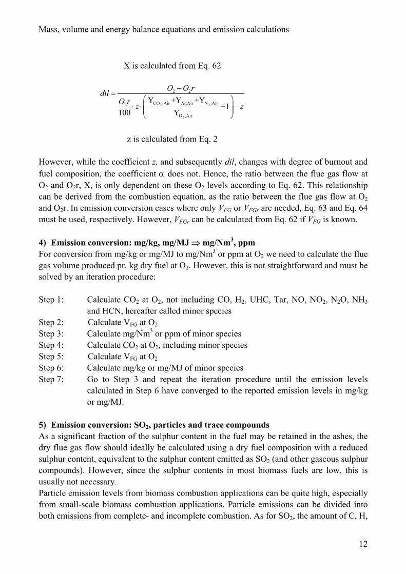
However, while the coefficient z, and subsequently dil, changes with degree of burnout andfuel composition, the coefficient α does not. Hence, the ratio between the flue gas flow atO2 and O2r, X, is only dependent on these O2 levels according to Eq. 62. This relationshipcan be derived from the combustion equation, as the ratio between the flue gas flow at O2
and O2r. In emission conversion cases where only VFG or VFGr are needed, Eq. 63 and Eq. 64must be used, respectively. However, VFGr can be calculated from Eq. 62 if VFG is known.
4) Emission conversion: mg/kg, mg/MJ ⇒ mg/Nm3, ppmFor conversion from mg/kg or mg/MJ to mg/Nm3 or ppm at O2 we need to calculate the fluegas volume produced pr. kg dry fuel at O2. However, this is not straightforward and must besolved by an iteration procedure:
Step 1: Calculate CO2 at O2, not including CO, H2, UHC, Tar, NO, NO2, N2O, NH3
and HCN, hereafter called minor speciesStep 2: Calculate VFG at O2
Step 3: Calculate mg/Nm3 or ppm of minor speciesStep 4: Calculate CO2 at O2, including minor speciesStep 5: Calculate VFG at O2
Step 6: Calculate mg/kg or mg/MJ of minor speciesStep 7: Go to Step 3 and repeat the iteration procedure until the emission levels
calculated in Step 6 have converged to the reported emission levels in mg/kgor mg/MJ.
5) Emission conversion: SO2, particles and trace compoundsAs a significant fraction of the sulphur content in the fuel may be retained in the ashes, thedry flue gas flow should ideally be calculated using a dry fuel composition with a reducedsulphur content, equivalent to the sulphur content emitted as SO2 (and other gaseous sulphurcompounds). However, since the sulphur contents in most biomass fuels are low, this isusually not necessary.Particle emission levels from biomass combustion applications can be quite high, especiallyfrom small-scale biomass combustion applications. Particle emissions can be divided intoboth emissions from complete- and incomplete combustion. As for SO2, the amount of C, H,
Mass, volume and energy balance equations and emission calculations
13
O, N and S emitted as particles should ideally be corrected for in the dry fuel compositionwhen calculating the dry flue gas flow. However, this is not necessary if the particleemission level is low.Emissions of trace compounds can safely be neglected when calculating the dry flue gasflow, since these emission levels do not significantly influence the calculated dry flue gasflow.
Mass, volume and energy balance equations and emission calculations
14
ENERGY CALCULATIONS:
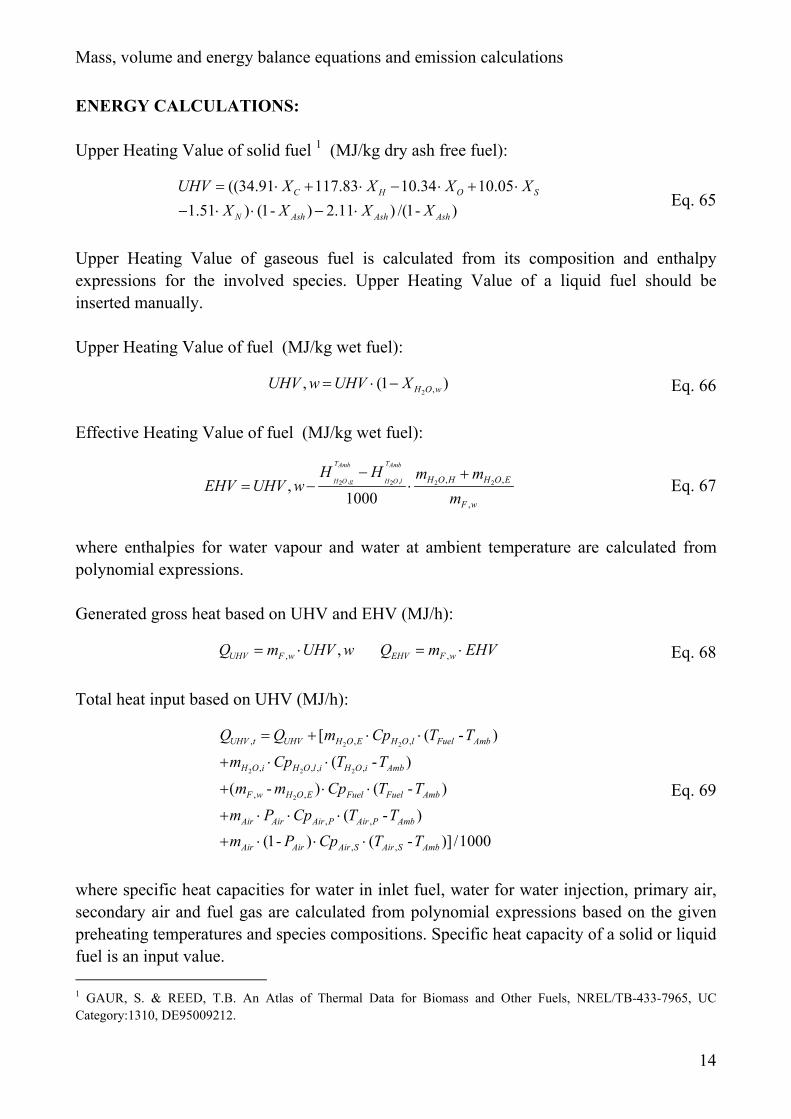
Upper Heating Value of solid fuel 1 (MJ/kg dry ash free fuel):
((34.91 117.83 10.34 10.051.51 ) (1- ) 2.11 ) /(1- )
C H O S
N Ash Ash Ash
UHV X X X XX X X X= ⋅ + ⋅ − ⋅ + ⋅
− ⋅ ⋅ − ⋅Eq. 65
Upper Heating Value of gaseous fuel is calculated from its composition and enthalpyexpressions for the involved species. Upper Heating Value of a liquid fuel should beinserted manually.
Upper Heating Value of fuel (MJ/kg wet fuel):
2 ,, (1 )H O wUHV w UHV X= ⋅ − Eq. 66
Effective Heating Value of fuel (MJ/kg wet fuel):
, ,2 2 2 2, ,
,
,1000
T TAmb Amb
H O g H O l H O H H O E
F w
H H m mEHV UHV w
m
− += − ⋅ Eq. 67
where enthalpies for water vapour and water at ambient temperature are calculated frompolynomial expressions.
Generated gross heat based on UHV and EHV (MJ/h):
, ,UHV F wQ m UHV w= ⋅ ,EHV F wQ m EHV= ⋅ Eq. 68
Total heat input based on UHV (MJ/h):
2 2
2 2 2
2
, , ,
, , , ,
, ,
, ,
, ,
[ ( - )
( - )
( - ) ( - )
( - )(1- ) ( - )] /1000
UHV t UHV H O E H O l Fuel Amb
H O i H O l i H O i Amb
F w H O E Fuel Fuel Amb
Air Air Air P Air P Amb
Air Air Air S Air S Amb
Q Q m Cp T T
m Cp T T
m m Cp T T
m P Cp T Tm P Cp T T
= + ⋅ ⋅
+ ⋅ ⋅
+ ⋅ ⋅
+ ⋅ ⋅ ⋅
+ ⋅ ⋅ ⋅
Eq. 69
where specific heat capacities for water in inlet fuel, water for water injection, primary air,secondary air and fuel gas are calculated from polynomial expressions based on the givenpreheating temperatures and species compositions. Specific heat capacity of a solid or liquidfuel is an input value. 1 GAUR, S. & REED, T.B. An Atlas of Thermal Data for Biomass and Other Fuels, NREL/TB-433-7965, UCCategory:1310, DE95009212.
Mass, volume and energy balance equations and emission calculations
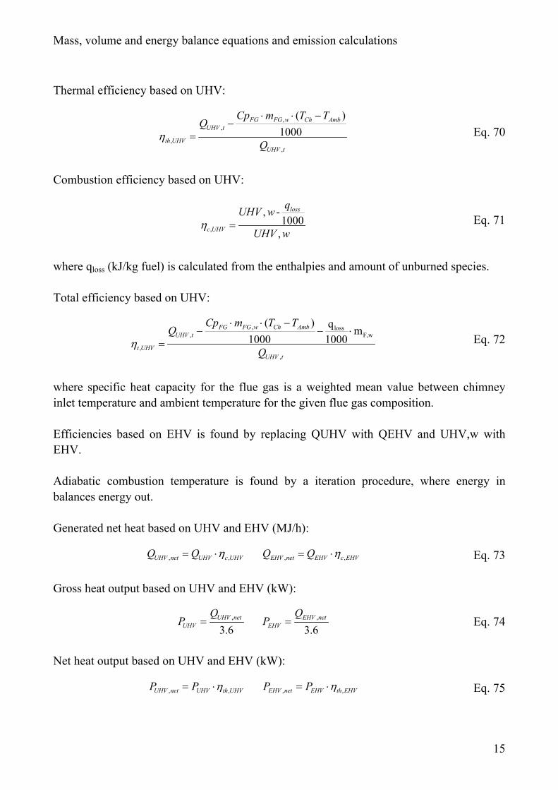
15
Thermal efficiency based on UHV:
,,
,,
( )1000
FG FG w Ch AmbUHV t
th UHVUHV t
Cp m T TQ
Qη
⋅ ⋅ −−
= Eq. 70
Combustion efficiency based on UHV:
,
, -1000
,
loss
c UHV
qUHV w
UHV wη = Eq. 71
where qloss (kJ/kg fuel) is calculated from the enthalpies and amount of unburned species.
Total efficiency based on UHV:
, loss, F,w
,,
( ) q m1000 1000
FG FG w Ch AmbUHV t
t UHVUHV t
Cp m T TQ
Qη
⋅ ⋅ −− − ⋅
= Eq. 72
where specific heat capacity for the flue gas is a weighted mean value between chimneyinlet temperature and ambient temperature for the given flue gas composition.
Efficiencies based on EHV is found by replacing QUHV with QEHV and UHV,w withEHV.
Adiabatic combustion temperature is found by a iteration procedure, where energy inbalances energy out.
Generated net heat based on UHV and EHV (MJ/h):
, ,UHV net UHV c UHVQ Q η= ⋅ , ,EHV net EHV c EHVQ Q η= ⋅ Eq. 73
Gross heat output based on UHV and EHV (kW):
,
3.6UHV net
UHV
QP = ,
3.6EHV net
EHV
QP = Eq. 74
Net heat output based on UHV and EHV (kW):
, ,UHV net UHV th UHVP P η= ⋅ , ,EHV net EHV th EHVP P η= ⋅ Eq. 75
Appendix 2
Fuelsim - Average introduction
Øyvind Skreiberg
August 2002
1
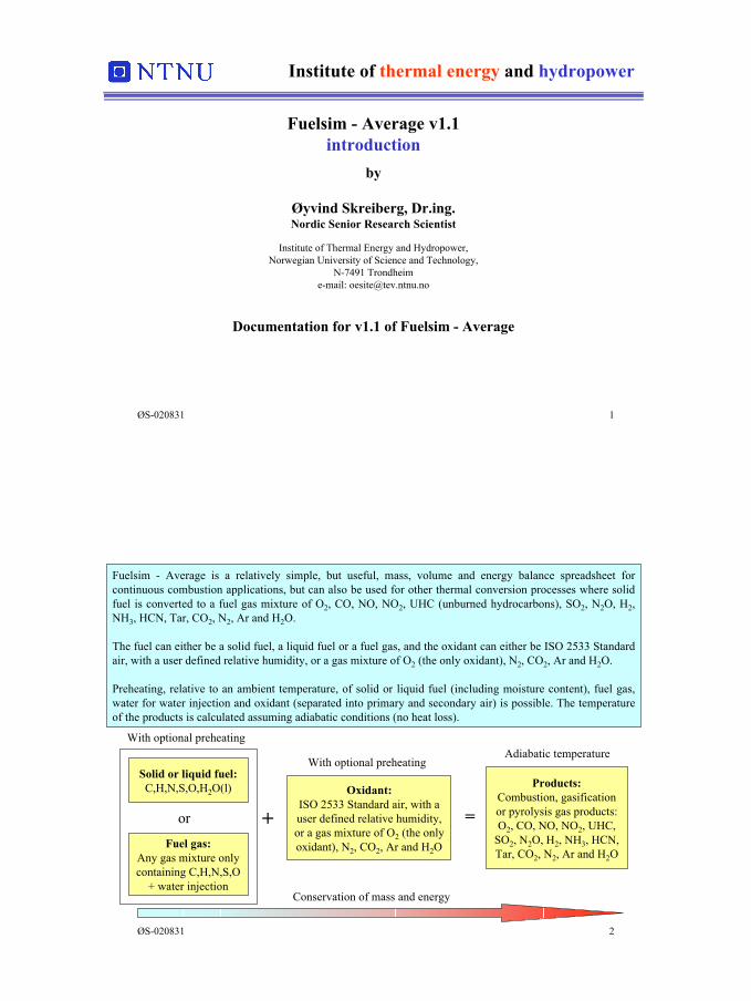
ØS-020831 1
Institute of thermal energy and hydropower
Fuelsim - Average v1.1introduction
by
Øyvind Skreiberg, Dr.ing.Nordic Senior Research Scientist
Institute of Thermal Energy and Hydropower,Norwegian University of Science and Technology,
N-7491 Trondheime-mail: [email protected]
Documentation for v1.1 of Fuelsim - Average
ØS-020831 2
Fuelsim - Average is a relatively simple, but useful, mass, volume and energy balance spreadsheet forcontinuous combustion applications, but can also be used for other thermal conversion processes where solidfuel is converted to a fuel gas mixture of O2, CO, NO, NO2, UHC (unburned hydrocarbons), SO2, N2O, H2,NH3, HCN, Tar, CO2, N2, Ar and H2O.
The fuel can either be a solid fuel, a liquid fuel or a fuel gas, and the oxidant can either be ISO 2533 Standardair, with a user defined relative humidity, or a gas mixture of O2 (the only oxidant), N2, CO2, Ar and H2O.
Preheating, relative to an ambient temperature, of solid or liquid fuel (including moisture content), fuel gas,water for water injection and oxidant (separated into primary and secondary air) is possible. The temperatureof the products is calculated assuming adiabatic conditions (no heat loss).
Products:Combustion, gasificationor pyrolysis gas products:O2, CO, NO, NO2, UHC,
SO2, N2O, H2, NH3, HCN,Tar, CO2, N2, Ar and H2O
Solid or liquid fuel:C,H,N,S,O,H2O(l)
Fuel gas:Any gas mixture onlycontaining C,H,N,S,O
+ water injection
Oxidant:ISO 2533 Standard air, with auser defined relative humidity,or a gas mixture of O2 (the onlyoxidant), N2, CO2, Ar and H2O
or + =
Conservation of mass and energy
With optional preheatingAdiabatic temperature
With optional preheating
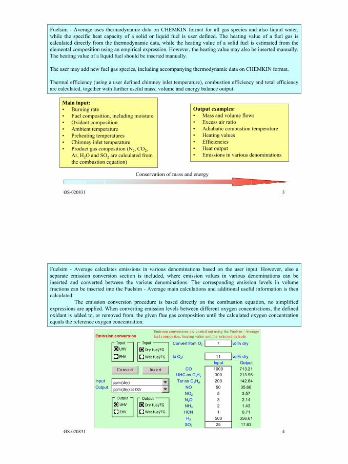
2
ØS-020831 3
Fuelsim - Average uses thermodynamic data on CHEMKIN format for all gas species and also liquid water,while the specific heat capacity of a solid or liquid fuel is user defined. The heating value of a fuel gas iscalculated directly from the thermodynamic data, while the heating value of a solid fuel is estimated from theelemental composition using an empirical expression. However, the heating value may also be inserted manually.The heating value of a liquid fuel should be inserted manually.
The user may add new fuel gas species, including accompanying thermodynamic data on CHEMKIN format.
Thermal efficiency (using a user defined chimney inlet temperature), combustion efficiency and total efficiencyare calculated, together with further useful mass, volume and energy balance output.
Conservation of mass and energy
Main input:• Burning rate• Fuel composition, including moisture• Oxidant composition• Ambient temperature• Preheating temperatures• Chimney inlet temperature• Product gas composition (N2, CO2,
Ar, H2O and SO2 are calculated fromthe combustion equation)
Output examples:• Mass and volume flows• Excess air ratio• Adiabatic combustion temperature• Heating values• Efficiencies• Heat output• Emissions in various denominations
ØS-020831 4
Fuelsim - Average calculates emissions in various denominations based on the user input. However, also aseparate emission conversion section is included, where emission values in various denominations can beinserted and converted between the various denominations. The corresponding emission levels in volumefractions can be inserted into the Fuelsim - Average main calculations and additional useful information is thencalculated.
The emission conversion procedure is based directly on the combustion equation, no simplifiedexpressions are applied. When converting emission levels between different oxygen concentrations, the definedoxidant is added to, or removed from, the given flue gas composition until the calculated oxygen concentrationequals the reference oxygen concentration.
Emission conversion
Convert from O2 7 vol% dry0
to O2r 11 vol% dryInput Output
CO 1000 713.21UHC as CxHy 300 213.96
Input Tar as CxtHyt 200 142.64Output NO 50 35.66
NO2 5 3.57N2O 3 2.14NH3 2 1.43HCN 1 0.71
H2 500 356.61SO2 25 17.83
Emission conversions are carried out using the Fuelsim - Averagefuel composition, heating value and the selec ted defaults
ppm (dry)
ppm (dry) at O2r
Output
UHV
EHV
Output
Dry fuel/FG
Wet fuel/FG
Input
UHV
EHV
Input
Dry fuel/FG
Wet fuel/FG
Conve rt Ins e rt
3
ØS-020831 5
Fuelsim - Average is an Excel spreadsheet and uses programmed functions and procedures in addition toformulas inserted directly in the spreadsheet cells. The user interface consists of input cells (marked with thecolour white) various push-buttons (marked with the colour grey), input forms (revealed when pushing a push-button), option-buttons (black: option is selected, white: option is not selected) and pull-down menus. Cellsmarked with the colour green are not user changeable.
The spreadsheet is protected to prevent accidental deletion of cell contents or objects. Formulas (onlyin the Average sheet), functions and procedures can not be seen by the user. However, all cells are selectablewhen using for example the Goal Seek command in Excel and other spreadsheets/sheets can refer to cells in theAverage sheet. Also, additional sheets can be inserted into the Fuelsim - Average spreadsheet.
Convert from O2 7 vol% dry
UHV
EHVppm (dry)
Volume fra ction
Input cell:Push-
button:
Pull-down menu:
Option-button:
Input box:
ØS-020831 6
Please direct questions, comments or proposals for improvements to Øyvind Skreiberg, TheNorwegian University of Science and Technology, Institute of Thermal Energy and Hydropower,N-7491 Trondheim, Norway, e-mail: [email protected]
Further information can be found in the documentation (push the Documentation push-button) and illustrative examples can be found by pushing the Examples push-button.
The Fuelsim - Average spreadsheet is an add-on to Chapter 2 - Basic principles of biomasscombustion, in the “Handbook of Biomass Combustion and Co-Firing”, which was compiled in a jointeffort by the country representatives in the IEA Task 32 - Biomass Combustion and Cofiring. Thehandbook can be ordered at, and possible updates to the Fuelsim - Average spreadsheet can bedownloaded from, the Task 32 www-site. Go to:
http://www.ieabioenergy-task32.com/
Appendix 3
Fuelsim - Average documentation
Øyvind Skreiberg
August 2002
1
ØS-020831 1
Institute of thermal energy and hydropower
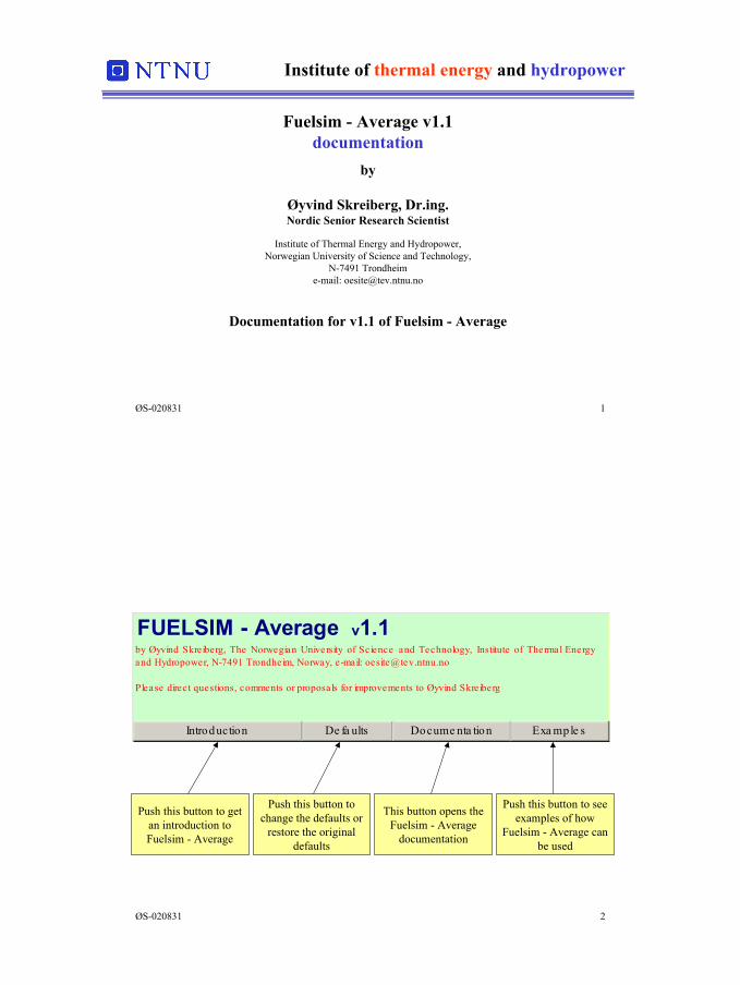
Fuelsim - Average v1.1documentation
by
Øyvind Skreiberg, Dr.ing.Nordic Senior Research Scientist
Institute of Thermal Energy and Hydropower,Norwegian University of Science and Technology,
N-7491 Trondheime-mail: [email protected]
Documentation for v1.1 of Fuelsim - Average
ØS-020831 2
Push this button to getan introduction toFuelsim - Average
Push this button tochange the defaults or
restore the originaldefaults
This button opens theFuelsim - Average
documentation
Push this button to seeexamples of how
Fuelsim - Average canbe used
FUELSIM - Average v1.1by Øyvind Skreiberg, The Norwegian University of Science and Technology, Institute of Thermal Energyand Hydropower, N-7491 Trondheim, Norway, e-mail: [email protected]
Please direc t questions, comments or proposals for improvements to Øyvind Skreiberg
Introduction De fa ults Docume nta tion Exa mple s
2
ØS-020831 3
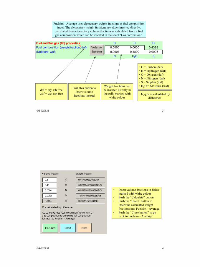
Fuel and flue gas (FG) properties C H OFuel composition (weight fraction, daf) 0.5000 0.0600 0.4388(Moisture: waf) 0.0007 0.1800 0.0005 N H2O S
Volume fra ction
Fuelsim - Average uses elementary weight fractions as fuel compositioninput. The elementary weight fractions are either inserted directly,
calculated from elementary volume fractions or calculated from a fuelgas composition which can be inserted in the sheet “Gas conversion”.
daf = dry ash freewaf = wet ash free
Push this button toinsert volume
fractions instead
Weight fractions canbe inserted directly inthe cells marked with
white colour
• C = Carbon (daf)• H = Hydrogen (daf)• O = Oxygen (daf)• N = Nitrogen (daf)• S = Sulphur (daf)• H2O = Moisture (waf)
Oxygen is calculated bydifference
ØS-020831 4
• Insert volume fractions in fieldsmarked with white colour
• Push the “Calculate” button• Push the “Insert” button to
insert the calculated weightfractions into Fuelsim - Average
• Push the “Close button” to goback to Fuelsim - Average
3
ØS-020831 5
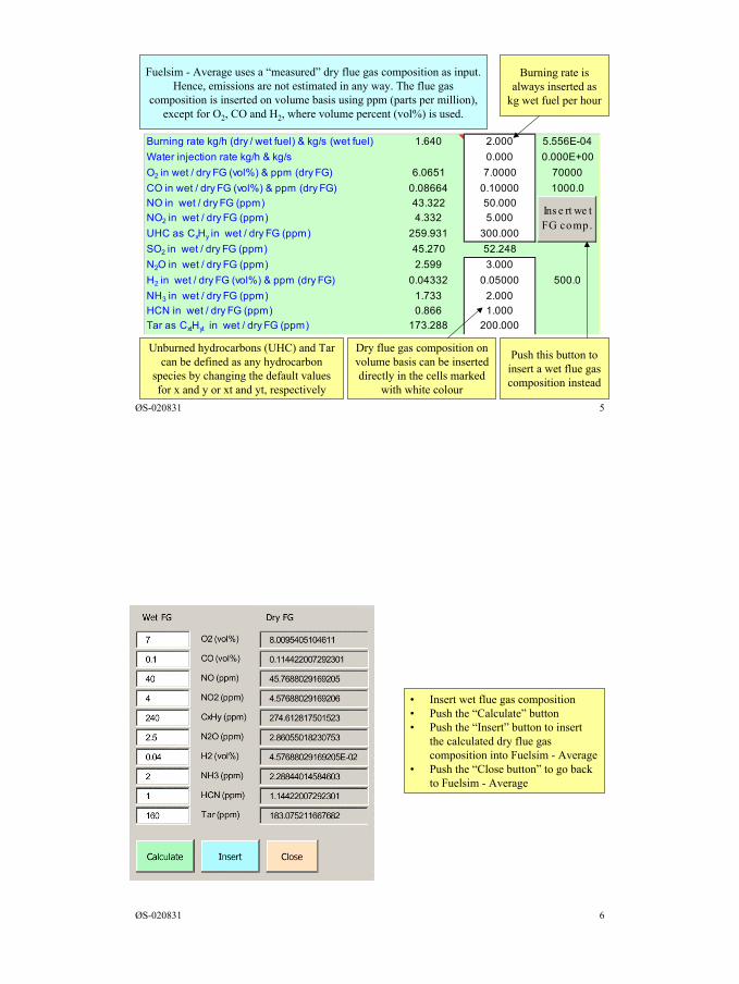
Burning rate kg/h (dry / wet fuel) & kg/s (wet fuel) 1.640 2.000 5.556E-04Water injection rate kg/h & kg/s 0.000 0.000E+00O2 in wet / dry FG (vol%) & ppm (dry FG) 6.0651 7.0000 70000CO in wet / dry FG (vol%) & ppm (dry FG) 0.08664 0.10000 1000.0NO in wet / dry FG (ppm) 43.322 50.000NO2 in wet / dry FG (ppm) 4.332 5.000UHC as CxHy in wet / dry FG (ppm) 259.931 300.000SO2 in wet / dry FG (ppm) 45.270 52.248N2O in wet / dry FG (ppm) 2.599 3.000H2 in wet / dry FG (vol%) & ppm (dry FG) 0.04332 0.05000 500.0NH3 in wet / dry FG (ppm) 1.733 2.000HCN in wet / dry FG (ppm) 0.866 1.000Tar as CxtHyt in wet / dry FG (ppm) 173.288 200.000
Ins e rt we t FG comp.
Fuelsim - Average uses a “measured” dry flue gas composition as input.Hence, emissions are not estimated in any way. The flue gas
composition is inserted on volume basis using ppm (parts per million),except for O2, CO and H2, where volume percent (vol%) is used.
Burning rate isalways inserted as
kg wet fuel per hour
Push this button toinsert a wet flue gascomposition instead
Dry flue gas composition onvolume basis can be inserteddirectly in the cells marked
with white colour
Unburned hydrocarbons (UHC) and Tarcan be defined as any hydrocarbon
species by changing the default valuesfor x and y or xt and yt, respectively
ØS-020831 6
• Insert wet flue gas composition• Push the “Calculate” button• Push the “Insert” button to insert
the calculated dry flue gascomposition into Fuelsim - Average
• Push the “Close button” to go backto Fuelsim - Average
4
ØS-020831 7
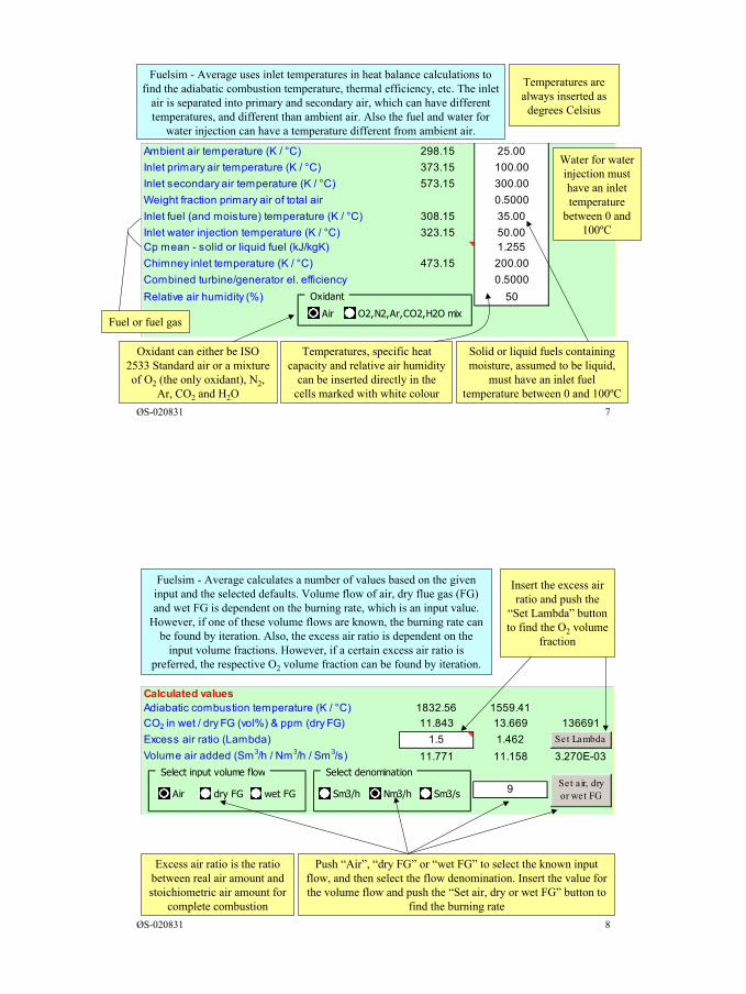
Ambient air temperature (K / °C) 298.15 25.00Inlet primary air temperature (K / °C) 373.15 100.00Inlet secondary air temperature (K / °C) 573.15 300.00Weight fraction primary air of total air 0.5000Inlet fuel (and moisture) temperature (K / °C) 308.15 35.00 Inlet water injection temperature (K / °C) 323.15 50.00 Cp mean - solid or liquid fuel (kJ/kgK) 1.255Chimney inlet temperature (K / °C) 473.15 200.00Combined turbine/generator el. efficiency 0.5000Relative air humidity (%) 50 Oxidant
Air O2,N2,Ar,CO2,H2O mix
Fuelsim - Average uses inlet temperatures in heat balance calculations tofind the adiabatic combustion temperature, thermal efficiency, etc. The inlet
air is separated into primary and secondary air, which can have differenttemperatures, and different than ambient air. Also the fuel and water for
water injection can have a temperature different from ambient air.
Temperatures arealways inserted as
degrees Celsius
Solid or liquid fuels containingmoisture, assumed to be liquid,
must have an inlet fueltemperature between 0 and 100ºC
Temperatures, specific heatcapacity and relative air humidity
can be inserted directly in thecells marked with white colour
Oxidant can either be ISO2533 Standard air or a mixtureof O2 (the only oxidant), N2,
Ar, CO2 and H2O
Fuel or fuel gas
Water for waterinjection musthave an inlettemperature
between 0 and100ºC
ØS-020831 8
Calculated values -2.4E-07Adiabatic combustion temperature (K / °C) 1832.56 1559.41CO2 in wet / dry FG (vol%) & ppm (dry FG) 11.843 13.669 136691Excess air ratio (Lambda) 1.5 1.462Volume air added (Sm3/h / Nm3/h / Sm3/s) 11.771 11.158 3.270E-03
9
Set Lambda
Set air, dryor wet FG
Select input volume flow
Air dry FG wet FG
Select denomination
Sm3/h Nm3/h Sm3/s
Fuelsim - Average calculates a number of values based on the giveninput and the selected defaults. Volume flow of air, dry flue gas (FG)and wet FG is dependent on the burning rate, which is an input value.
However, if one of these volume flows are known, the burning rate canbe found by iteration. Also, the excess air ratio is dependent on the
input volume fractions. However, if a certain excess air ratio ispreferred, the respective O2 volume fraction can be found by iteration.
Insert the excess airratio and push the
“Set Lambda” buttonto find the O2 volume
fraction
Push “Air”, “dry FG” or “wet FG” to select the known inputflow, and then select the flow denomination. Insert the value forthe volume flow and push the “Set air, dry or wet FG” button to
find the burning rate
Excess air ratio is the ratiobetween real air amount andstoichiometric air amount for
complete combustion
5
ØS-020831 9
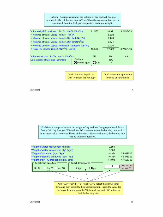
Volume dry FG produced (Sm3/h / Nm3/h / Sm3/s) 11.573 10.971 3.215E-03 + Volume of water vapour from H (Nm3/h) 1.069 + Volume of water vapour from H2O in fuel (Nm3/h) 0.448 + Volume of water vapour from H2O in air (Nm3/h) 0.174 + Volume of water vapour from water injection (Nm3/h) 0.000 = Total FG volume (Sm3/h / Nm3/h / Sm3/s) 13.357 12.662 3.710E-03
Volume fuel gas (Sm3/h / Nm3/h / Sm3/s) NA NA NAMole weight of fuel gas (kg/kmole) NAFuel type
Solid or liquid Gas
Fuelsim - Average calculates the volume of dry and wet flue gasproduced. Also, if the fuel type is “Gas” then the volume of fuel gas is
calculated from the fuel gas composition and mole weight.
Push “Solid or liquid” or“Gas” to select the fuel type
“NA” means not applicablefor solid or liquid fuels
ØS-020831 10
Fuelsim - Average calculates the weight of dry and wet flue gas produced. Massflow of air, dry flue gas (FG) and wet FG is dependent on the burning rate, whichis an input value. However, if one of these mass flows are known, the burning rate
can be found by iteration.
Weight of water vapour from H (kg/h) 0.859 0.879Weight of water vapour from H2O (kg/h) 0.360Weight of air added (kg/h / kg/s) 14.334 3.982E-03Weight of total FG produced (kg/h / kg/s) 16.334 4.537E-03Weight of dry FG produced (kg/h / kg/s) 14.975 4.160E-03
12 Set a ir, dryor wet FG
Select input mass flow
Air dry FG wet FG
Select denomination
kg/h kg/s
Push “Air”, “dry FG” or “wet FG” to select the known inputflow, and then select the flow denomination. Insert the value for
the mass flow and push the “Set air, dry or wet FG” button tofind the burning rate
6
ØS-020831 11
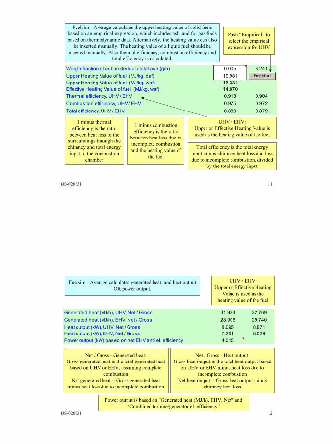
Weigth fraction of ash in dry fuel / total ash (g/h) 0.005 8.241Upper Heating Value of fuel (MJ/kg, daf) 19.981Upper Heating Value of fuel (MJ/kg, waf) 16.384Effective Heating Value of fuel (MJ/kg, waf) 14.870Thermal efficiency, UHV / EHV 0.913 0.904Combustion efficiency, UHV / EHV 0.975 0.972Total efficiency, UHV / EHV 0.889 0.879
Empirical
Fuelsim - Average calculates the upper heating value of solid fuelsbased on an empirical expression, which includes ash, and for gas fuelsbased on thermodynamic data. Alternatively, the heating value can also
be inserted manually. The heating value of a liquid fuel should beinserted manually. Also thermal efficiency, combustion efficiency and
total efficiency is calculated.
1 minus thermalefficiency is the ratio
between heat loss to thesurroundings through thechimney and total energyinput to the combustion
chamber
Push “Empirical” toselect the empiricalexpression for UHV
1 minus combustionefficiency is the ratio
between heat loss due toincomplete combustionand the heating value of
the fuel
Total efficiency is the total energyinput minus chimney heat loss and lossdue to incomplete combustion, divided
by the total energy input
UHV / EHV:Upper or Effective Heating Value isused as the heating value of the fuel
ØS-020831 12
Fuelsim - Average calculates generated heat, and heat outputOR power output.
UHV / EHV:Upper or Effective Heating
Value is used as theheating value of the fuel
Net / Gross - Generated heat:Gross generated heat is the total generated heat
based on UHV or EHV, assuming completecombustion
Net generated heat = Gross generated heatminus heat loss due to incomplete combustion
Net / Gross - Heat output:Gross heat output is the total heat output based
on UHV or EHV minus heat loss due toincomplete combustion
Net heat output = Gross heat output minuschimney heat loss
Power output is based on "Generated heat (MJ/h), EHV, Net" and“Combined turbine/generator el. efficiency”
Generated heat (MJ/h), UHV, Net / Gross 31.934 32.769Generated heat (MJ/h), EHV, Net / Gross 28.906 29.740Heat output (kW), UHV, Net / Gross 8.095 8.871Heat output (kW), EHV, Net / Gross 7.261 8.029Power output (kW) based on net EHV and el. efficiency 4.015
7
ØS-020831 13
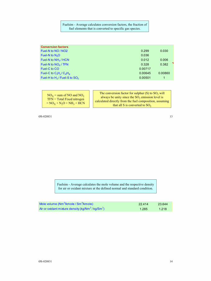
Fuelsim - Average calculates conversion factors, the fraction offuel elements that is converted to specific gas species.
The conversion factor for sulphur (S) to SO2 willalways be unity since the SO2 emission level is
calculated directly from the fuel composition, assumingthat all S is converted to SO2
NOX = sum of NO and NO2TFN = Total Fixed nitrogen= NOX + N2O + NH3 + HCN
Conversion factorsFuel-N to NO / NO2 0.299 0.030Fuel-N to N2O 0.036Fuel-N to NH3 / HCN 0.012 0.006Fuel-N to NOX / TFN 0.328 0.382Fuel-C to CO 0.00717Fuel-C to CxHy / CxtHyt 0.00645 0.00860Fuel-H to H2 / Fuel-S to SO2 0.00501 1
ØS-020831 14
Fuelsim - Average calculates the mole volume and the respective densityfor air or oxidant mixture at the defined normal and standard condition.
Mole volume (Nm3/kmole / Sm3/kmole) 22.414 23.644Air or oxidant mixture density (kg/Nm3 / kg/Sm3) 1.285 1.218
8
ØS-020831 15
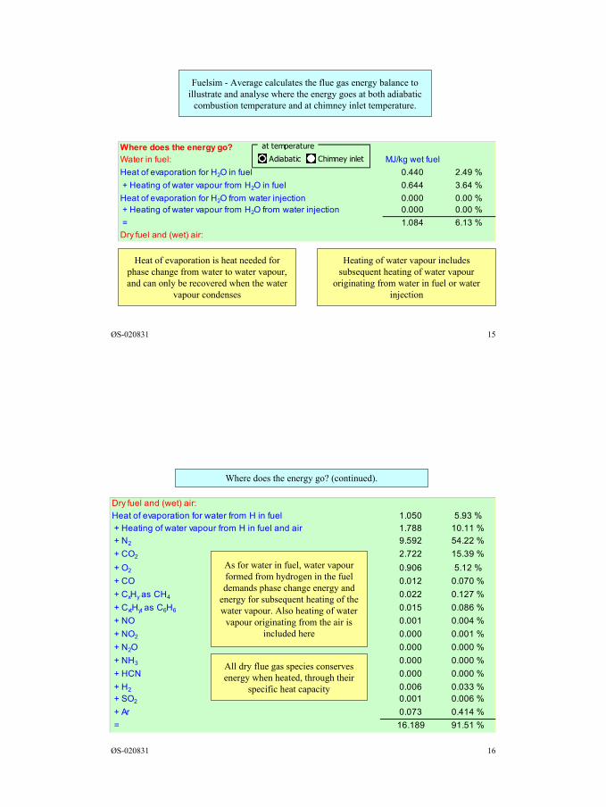
Fuelsim - Average calculates the flue gas energy balance toillustrate and analyse where the energy goes at both adiabatic
combustion temperature and at chimney inlet temperature.
Heat of evaporation is heat needed forphase change from water to water vapour,and can only be recovered when the water
vapour condenses
Heating of water vapour includessubsequent heating of water vapour
originating from water in fuel or waterinjection
Where does the energy go?Water in fuel: MJ/kg wet fuelHeat of evaporation for H2O in fuel 0.440 2.49 % + Heating of water vapour from H2O in fuel 0.644 3.64 %Heat of evaporation for H2O from water injection 0.000 0.00 % + Heating of water vapour from H2O from water injection 0.000 0.00 % = 1.084 6.13 %Dry fuel and (wet) air:
at temperature
Adiabatic Chimney inlet
ØS-020831 16
Dry fuel and (wet) air:Heat of evaporation for water from H in fuel 1.050 5.93 % + Heating of water vapour from H in fuel and air 1.788 10.11 % + N2 9.592 54.22 % + CO2 2.722 15.39 % + O2 0.906 5.12 % + CO 0.012 0.070 % + CxHy as CH4 0.022 0.127 % + CxtHyt as C6H6 0.015 0.086 % + NO 0.001 0.004 % + NO2 0.000 0.001 % + N2O 0.000 0.000 % + NH3 0.000 0.000 % + HCN 0.000 0.000 % + H2 0.006 0.033 % + SO2 0.001 0.006 % + Ar 0.073 0.414 % = 16.189 91.51 %
Where does the energy go? (continued).
As for water in fuel, water vapourformed from hydrogen in the fueldemands phase change energy and
energy for subsequent heating of thewater vapour. Also heating of water
vapour originating from the air isincluded here
All dry flue gas species conservesenergy when heated, through their
specific heat capacity
9
ØS-020831 17
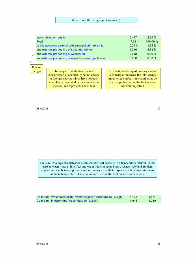
Incomplete combustion meansconservation of chemically bound energyin fuel gas species which have not beencompletely converted in the combustion
process, and represents a heat loss
Where does the energy go? (continued).
External preheating of primary and/orsecondary air increase the total energyinput to the combustion chamber, as doexternal preheating of the fuel or water
for water injection
Fuel orfuel gas
Incomplete combustion 0.417 2.36 %Total 17.691 100.00 %of this accounts external preheating of primary air for 0.273 1.54 %and external preheating of secondary air for 1.016 5.74 %and external preheating of wet fuel for 0.018 0.10 %and external preheating of water for water injection for 0.000 0.00 %
ØS-020831 18
Fuelsim - Average calculates the mean specific heat capacity in a temperature interval, in thiscase between water at inlet fuel and water injection temperature respectively and ambient
temperature, and between primary and secondary air at their respective inlet temperatures andambient temperature. These values are used in the heat balance calculations.
Cp mean - Water, at inlet fuel / water injection temperature (kJ/kgK) 4.178 4.177Cp mean - Inlet primary / secondary air (kJ/kgK) 1.016 1.030
10
ØS-020831 19
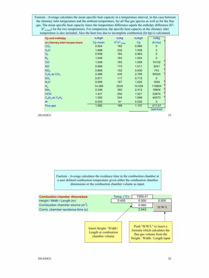
Fuelsim - Average calculates the mean specific heat capacity in a temperature interval, in this case betweenthe chimney inlet temperature and the ambient temperature, for all flue gas species as well as for the fluegas. The mean specific heat capacity times the temperature difference equals the enthalpy difference (h0-
h0,TAmb) for the two temperatures. For comparison, the specific heat capacity at the chimney inlet
temperature is also included. Also the heat loss due to incomplete combustion (hr-hp) is calculated.Cp and enthalpy kJ/kgK kJ/kg kJ/kgK kJ/kgat chimney inlet temperature Cp mean h0-h0
,TAmb Cp (hr-hp)CO2 0.924 162 0.995 0H2O 1.898 332 1.939 0O2 0.938 164 0.963 0N2 1.046 183 1.054 0CO 1.048 183 1.059 10102NO 0.999 175 1.011 3041NO2 0.869 152 0.930 743CxHy as CH4 2.488 435 2.795 50024SO2 0.671 117 0.715 0N2O 0.956 167 1.025 1854H2 14.480 2534 14.539 119954NH3 2.246 393 2.412 18604HCN 1.431 250 1.521 23874CxtHyt as C6H6 1.392 244 1.698 40573Ar 0.520 91 0.520 0Flue gas 1.082 189 1.107 417.47
(wet fuel)
ØS-020831 20
Combustion chamber dimensions Temp. (°C): 1559.41Height / Width / Length (m) 0.400 0.300 0.500Combustion chamber volume (m3) 0.060Comb. chamber residence time (s) 2.543
H/W/L
Fuelsim - Average calculates the residence time in the combustion chamber ata user defined combustion temperature given either the combustion chamber
dimensions or the combustion chamber volume as input.
Insert Height / Width /Length or combustion
chamber volume
Push “H/W/L” to insert aformula which calculates the
flue gas volume from theHeight / Width / Length input
11
ØS-020831 21
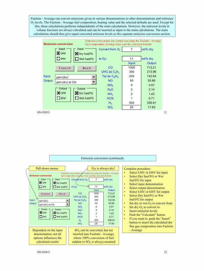
Fuelsim - Average can convert emissions given in various denominations to other denominations and referenceO2 levels. The Fuelsim - Average fuel composition, heating value and the selected defaults are used. Except for
this, these calculations performs independently of the main calculations. However, the emission levels involume fractions are always calculated and can be inserted as input to the main calculations. The main
calculations should then give equal converted emission levels as this separate emission conversion section.
Emission conversion
Convert from O2 7 vol% dry0
to O2r 11 vol% dryInput Output
CO 1000 713.21UHC as CxHy 300 213.96
Input Tar as CxtHyt 200 142.64Output NO 50 35.66
NO2 5 3.57N2O 3 2.14NH3 2 1.43HCN 1 0.71
H2 500 356.61SO2 25 17.83
Emission conversions are carried out using the Fuelsim - Averagefuel composition, heating value and the se lected defaults
ppm (dry)
ppm (dry) at O2r
Output
UHV
EHV
Output
Dry fuel/FG
Wet fuel/FG
Input
UHV
EHV
Input
Dry fuel/FG
Wet fuel/FG
Conve rt Ins e rt
ØS-020831 22
Emission conversion
Convert from O2 7 vol% dry0
to O2r 11 vol% dryInput Output
CO 1000 713.21UHC as CxHy 300 213.96
Input Tar as CxtHyt 200 142.64Output NO 50 35.66
NO2 5 3.57N2O 3 2.14NH3 2 1.43HCN 1 0.71
H2 500 356.61SO2 25 17.83
Emission conversions are carried out using the Fuelsim - Averagefuel composition, heating value and the se lected defaults
ppm (dry)
ppm (dry) at O2r
Output
UHV
EHV
Output
Dry fuel/FG
Wet fuel/FG
Input
UHV
EHV
Input
Dry fuel/FG
Wet fuel/FG
Conve rt Ins e rt
Emission conversion (continued).
Complete procedure:• Select UHV or EHV for input• Select Dry fuel/FG or Wet
fuel/FG for input• Select input denomination• Select output denomination• Select UHV or EHV for output• Select Dry fuel/FG or Wet
fuel/FG for output• Set dry or wet O2 to convert from• Set dry O2 to convert to• Insert emission levels• Push the “Calculate” button• If you want to, push the “Insert”
button to insert the calculated dryflue gas composition into Fuelsim- AverageDependent on the input
denomination, not alloptions influences the
calculated results
SO2 can be converted, but notinserted into Fuelsim - Average,where 100% conversion of fuel
sulphur to SO2 is always assumed
Pull-down menus O2r is always dry!
12
ØS-020831 23
Inputmg/Nm3 (dry)ppm (dry)mg/kg (dry)mg/MJ (UHV)mg/kWh (UHV)
Inputmg/Nm3 (wet)ppm (wet)mg/kg (wet)mg/MJ (EHV)mg/kWh (EHV)
Outputmg/Nm3 (dry) at O2rppm (dry) at O2rmg/kg (dry), O2r = O2mg/MJ (UHV), O2r = O2mg/kWh (UHV), O2r = O2ppm (dry) at O2r = O2
Outputmg/Nm3 (wet) at O2rppm (wet) at O2rmg/kg (wet), O2r = O2mg/MJ (EHV), O2r = O2mg/kWh (EHV), O2r = O2ppm (wet) at O2r = O2
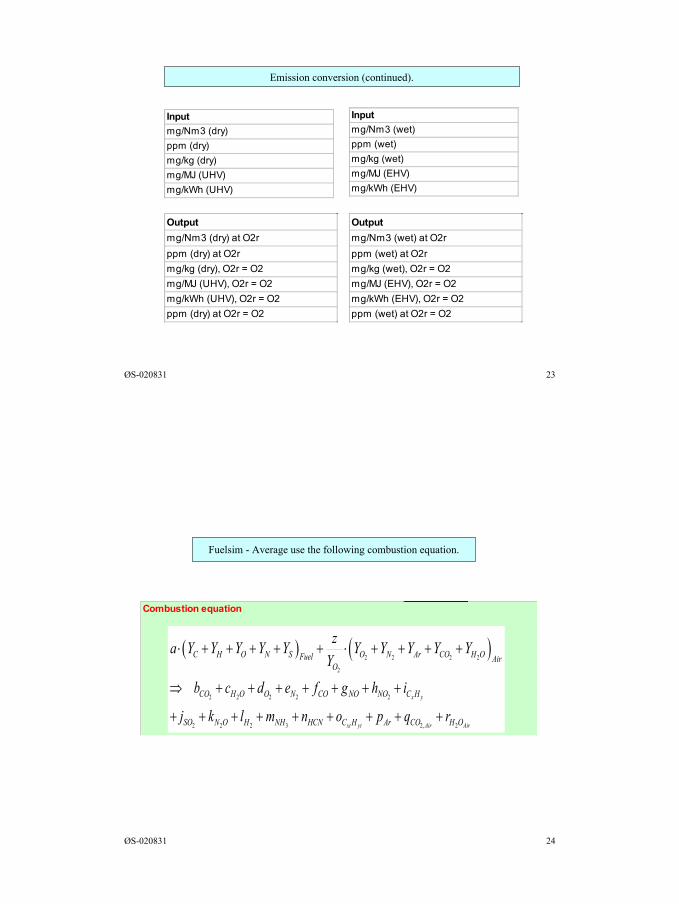
Emission conversion (continued).
ØS-020831 24
Fuelsim - Average use the following combustion equation.
Combustion equation
( ) ( )2 2 2 2
2
2 2 2 2 2
2 2 2 3 2, 2
x y
xt yt Air Air
C H O N S O N Ar CO H OFuel AirO
CO H O O N CO NO NO C H
SO N O H NH HCN C H Ar CO H O
za Y Y Y Y Y Y Y Y Y YY
b c d e f g h i
j k l m n o p q r
⋅ + + + + + ⋅ + + + +
⇒ + + + + + + +
+ + + + + + + + +
13
ØS-020831 25
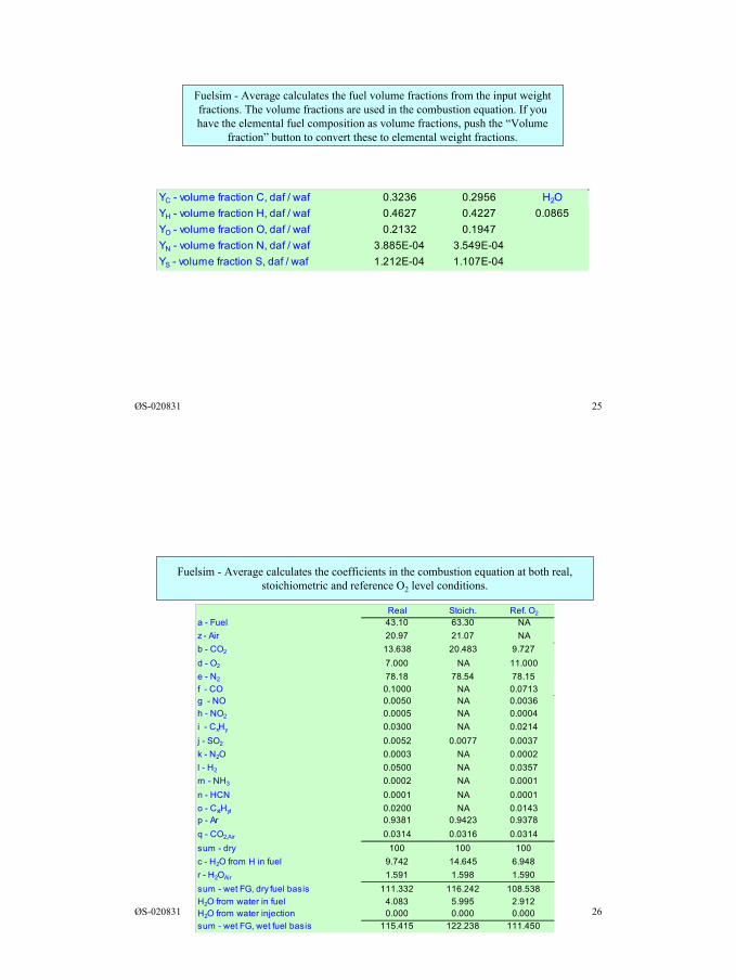
Fuelsim - Average calculates the fuel volume fractions from the input weightfractions. The volume fractions are used in the combustion equation. If youhave the elemental fuel composition as volume fractions, push the “Volume
fraction” button to convert these to elemental weight fractions.
YC - volume fraction C, daf / waf 0.3236 0.2956 H2OYH - volume fraction H, daf / waf 0.4627 0.4227 0.0865YO - volume fraction O, daf / waf 0.2132 0.1947YN - volume fraction N, daf / waf 3.885E-04 3.549E-04 0.002985YS - volume fraction S, daf / waf 1.212E-04 1.107E-04 0.002985
ØS-020831 26
Fuelsim - Average calculates the coefficients in the combustion equation at both real,stoichiometric and reference O2 level conditions.
Real Stoich. Ref. O2
a - Fuel 43.10 63.30 NAz - Air 20.97 21.07 NAb - CO2 13.638 20.483 9.727d - O2 7.000 NA 11.000e - N2 78.18 78.54 78.15f - CO 0.1000 NA 0.0713g - NO 0.0050 NA 0.0036h - NO2 0.0005 NA 0.0004i - CxHy 0.0300 NA 0.0214j - SO2 0.0052 0.0077 0.0037k - N2O 0.0003 NA 0.0002l - H2 0.0500 NA 0.0357m - NH3 0.0002 NA 0.0001n - HCN 0.0001 NA 0.0001o - CxtHyt 0.0200 NA 0.0143p - Ar 0.9381 0.9423 0.9378q - CO2,Air 0.0314 0.0316 0.0314sum - dry 100 100 100c - H2O from H in fuel 9.742 14.645 6.948r - H2OAir 1.591 1.598 1.590sum - wet FG, dry fuel basis 111.332 116.242 108.538H2O from water in fuel 4.083 5.995 2.912H2O from water injection 0.000 0.000 0.000sum - wet FG, wet fuel basis 115.415 122.238 111.450
14
ØS-020831 27
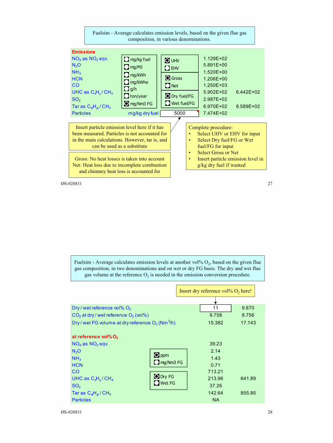
Fuelsim - Average calculates emission levels, based on the given flue gascomposition, in various denominations.
Insert particle emission level here if it hasbeen measured. Particles is not accounted forin the main calculations. However, tar is, and
can be used as a substitute
Complete procedure:• Select UHV or EHV for input• Select Dry fuel/FG or Wet
fuel/FG for input• Select Gross or Net• Insert particle emission level in
g/kg dry fuel if wantedGross: No heat losses is taken into account
Net: Heat loss due to incomplete combustionand chimney heat loss is accounted for
EmissionsNOX as NO2 eqv. 1.129E+02N2O 5.891E+00NH3 1.520E+00HCN 1.206E+00CO 1.250E+03UHC as CxHy / CH4 5.902E+02 6.442E+02SO2 2.987E+02Tar as CxtHyt / CH4 6.970E+02 8.589E+02Particles mg/kg dry fuel 5000 7.474E+02
mg/kg fuel
mg/MJ
mg/kWh
g/h
ton/year
UHV
EHV
mg/Nm3 FG
Dry fuel/FG
Wet fuel/FG
Gross
Netmg/kWhe
ØS-020831 28
Fuelsim - Average calculates emission levels at another vol% O2, based on the given fluegas composition, in two denominations and on wet or dry FG basis. The dry and wet flue
gas volume at the reference O2 is needed in the emission conversion procedure.
Insert dry reference vol% O2 here!
Dry / wet reference vol% O2 11 9.870CO2 at dry / wet reference O2 (vol%) 9.758 8.756Dry / wet FG volume at dry reference O2 (Nm3/h) 15.382 17.143
at reference vol% O2
NOX as NO2 eqv. 39.23N2O 2.14NH3 1.43HCN 0.71CO 713.21UHC as CxHy / CH4 213.96 641.89SO2 37.26Tar as CxtHyt / CH4 142.64 855.85Particles NA
Dry FGWet FG
ppm
mg/Nm3 FG
15
ØS-020831 29
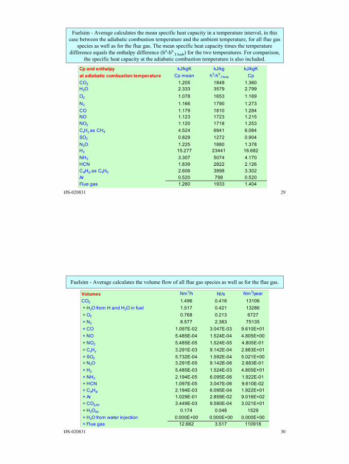
Fuelsim - Average calculates the mean specific heat capacity in a temperature interval, in thiscase between the adiabatic combustion temperature and the ambient temperature, for all flue gas
species as well as for the flue gas. The mean specific heat capacity times the temperaturedifference equals the enthalpy difference (h0-h0
,TAmb) for the two temperatures. For comparison,the specific heat capacity at the adiabatic combustion temperature is also included.
Cp and enthalpy kJ/kgK kJ/kg kJ/kgKat adiabatic combustion temperature Cp mean h0-h0
,TAmb CpCO2 1.205 1849 1.360H2O 2.333 3579 2.799O2 1.078 1653 1.169N2 1.166 1790 1.273CO 1.179 1810 1.284NO 1.123 1723 1.215NO2 1.120 1718 1.253CxHy as CH4 4.524 6941 6.084SO2 0.829 1272 0.904N2O 1.225 1880 1.378H2 15.277 23441 16.682NH3 3.307 5074 4.170HCN 1.839 2822 2.126CxtHyt as C6H6 2.606 3998 3.302Ar 0.520 798 0.520Flue gas 1.260 1933 1.404
ØS-020831 30
Fuelsim - Average calculates the volume flow of all flue gas species as well as for the flue gas.
Volumes Nm3/h Nl/s Nm3/yearCO2 1.496 0.416 13106 + H2O from H and H2O in fuel 1.517 0.421 13286 + O2 0.768 0.213 6727 + N2 8.577 2.383 75135 + CO 1.097E-02 3.047E-03 9.610E+01 + NO 5.485E-04 1.524E-04 4.805E+00 + NO2 5.485E-05 1.524E-05 4.805E-01 + CxHy 3.291E-03 9.142E-04 2.883E+01 + SO2 5.732E-04 1.592E-04 5.021E+00 + N2O 3.291E-05 9.142E-06 2.883E-01 + H2 5.485E-03 1.524E-03 4.805E+01 + NH3 2.194E-05 6.095E-06 1.922E-01 + HCN 1.097E-05 3.047E-06 9.610E-02 + CxtHyt 2.194E-03 6.095E-04 1.922E+01 + Ar 1.029E-01 2.859E-02 9.016E+02 + CO2,Air 3.449E-03 9.580E-04 3.021E+01 + H2OAir 0.174 0.048 1529 + H2O from water injection 0.000E+00 0.000E+00 0.000E+00 = Flue gas 12.662 3.517 110918
16
ØS-020831 31
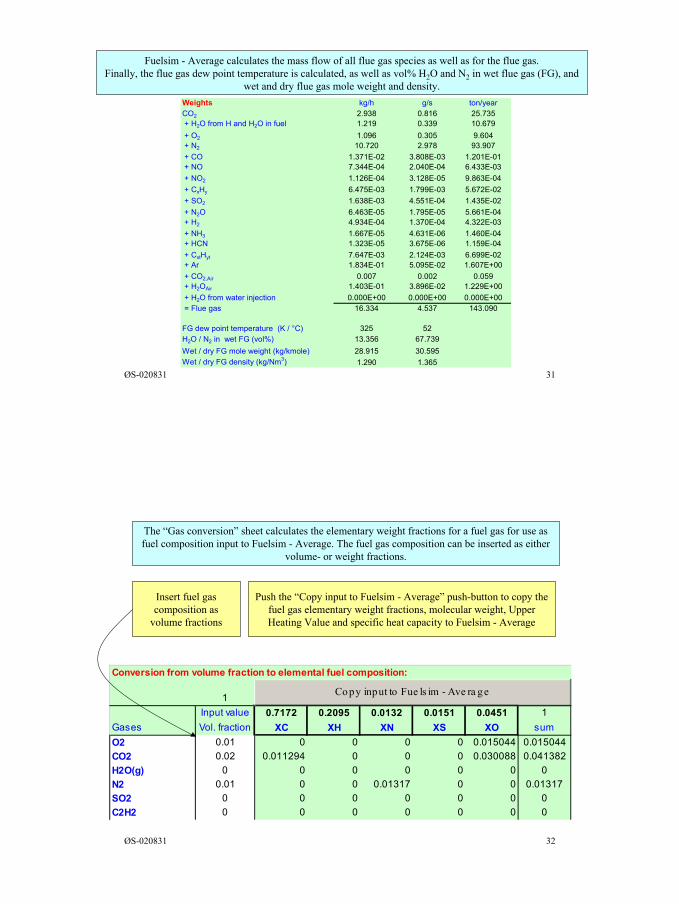
Fuelsim - Average calculates the mass flow of all flue gas species as well as for the flue gas.Finally, the flue gas dew point temperature is calculated, as well as vol% H2O and N2 in wet flue gas (FG), and
wet and dry flue gas mole weight and density.Weights kg/h g/s ton/yearCO2 2.938 0.816 25.735+ H2O from H and H2O in fuel 1.219 0.339 10.679 + O2 1.096 0.305 9.604+ N2 10.720 2.978 93.907 + CO 1.371E-02 3.808E-03 1.201E-01+ NO 7.344E-04 2.040E-04 6.433E-03 + NO2 1.126E-04 3.128E-05 9.863E-04 + CxHy 6.475E-03 1.799E-03 5.672E-02 + SO2 1.638E-03 4.551E-04 1.435E-02 + N2O 6.463E-05 1.795E-05 5.661E-04+ H2 4.934E-04 1.370E-04 4.322E-03 + NH3 1.667E-05 4.631E-06 1.460E-04+ HCN 1.323E-05 3.675E-06 1.159E-04 + CxtHyt 7.647E-03 2.124E-03 6.699E-02+ Ar 1.834E-01 5.095E-02 1.607E+00 + CO2,Air 0.007 0.002 0.059+ H2OAir 1.403E-01 3.896E-02 1.229E+00 + H2O from water injection 0.000E+00 0.000E+00 0.000E+00 = Flue gas 16.334 4.537 143.090
FG dew point temperature (K / °C) 325 52H2O / N2 in wet FG (vol%) 13.356 67.739Wet / dry FG mole weight (kg/kmole) 28.915 30.595Wet / dry FG density (kg/Nm3) 1.290 1.365
ØS-020831 32
Conversion from volume fraction to elemental fuel composition:
1Input value 0.7172 0.2095 0.0132 0.0151 0.0451 1
Gases Vol. fraction XC XH XN XS XO sumO2 0.01 0 0 0 0 0.015044 0.015044CO2 0.02 0.011294 0 0 0 0.030088 0.041382H2O(g) 0 0 0 0 0 0 0N2 0.01 0 0 0.01317 0 0 0.01317SO2 0 0 0 0 0 0 0C2H2 0 0 0 0 0 0 0
Copy input to Fue ls im - Ave ra ge
The “Gas conversion” sheet calculates the elementary weight fractions for a fuel gas for use asfuel composition input to Fuelsim - Average. The fuel gas composition can be inserted as either
volume- or weight fractions.
Insert fuel gascomposition as
volume fractions
Push the “Copy input to Fuelsim - Average” push-button to copy thefuel gas elementary weight fractions, molecular weight, UpperHeating Value and specific heat capacity to Fuelsim - Average
17
ØS-020831 33
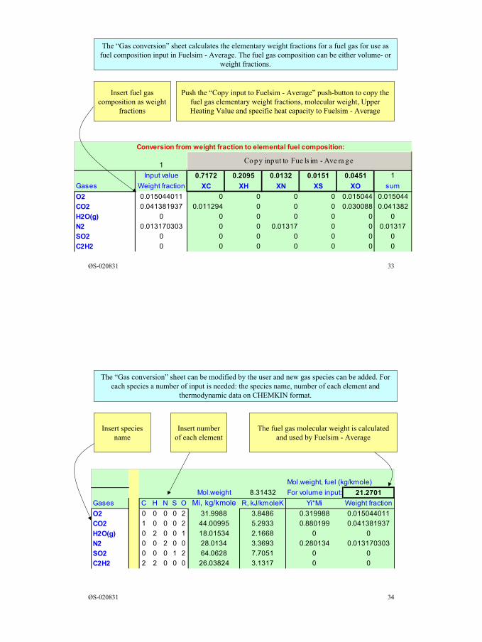
Conversion from vConversion from weight fraction to elemental fuel composition:
1Input value 0.7172 0.2095 0.0132 0.0151 0.0451 1
Gases Weight fraction XC XH XN XS XO sumO2 0.015044011 0 0 0 0 0.015044 0.015044CO2 0.041381937 0.011294 0 0 0 0.030088 0.041382H2O(g) 0 0 0 0 0 0 0N2 0.013170303 0 0 0.01317 0 0 0.01317SO2 0 0 0 0 0 0 0C2H2 0 0 0 0 0 0 0
Copy input to Fue ls im - Ave ra ge
The “Gas conversion” sheet calculates the elementary weight fractions for a fuel gas for use asfuel composition input in Fuelsim - Average. The fuel gas composition can be either volume- or
weight fractions.
Insert fuel gascomposition as weight
fractions
Push the “Copy input to Fuelsim - Average” push-button to copy thefuel gas elementary weight fractions, molecular weight, UpperHeating Value and specific heat capacity to Fuelsim - Average
ØS-020831 34
Mol.weight, fuel (kg/kmole)Mol.weight 8.31432 For volume input: 21.2701
Gases C H N S O Mi, kg/kmole R, kJ/kmoleK Yi*Mi Weight fractionO2 0 0 0 0 2 31.9988 3.8486 0.319988 0.015044011CO2 1 0 0 0 2 44.00995 5.2933 0.880199 0.041381937H2O(g) 0 2 0 0 1 18.01534 2.1668 0 0N2 0 0 2 0 0 28.0134 3.3693 0.280134 0.013170303SO2 0 0 0 1 2 64.0628 7.7051 0 0C2H2 2 2 0 0 0 26.03824 3.1317 0 0
The “Gas conversion” sheet can be modified by the user and new gas species can be added. Foreach species a number of input is needed: the species name, number of each element and
thermodynamic data on CHEMKIN format.
Insert numberof each element
The fuel gas molecular weight is calculatedand used by Fuelsim - Average
Insert speciesname
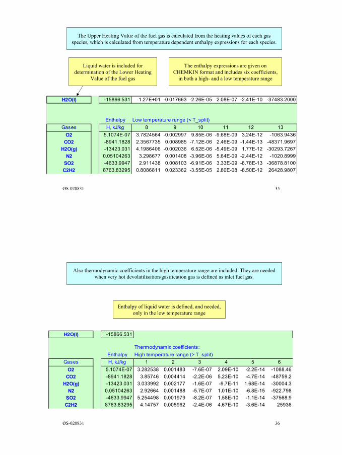
18
ØS-020831 35
The Upper Heating Value of the fuel gas is calculated from the heating values of each gasspecies, which is calculated from temperature dependent enthalpy expressions for each species.
Liquid water is included fordetermination of the Lower Heating
Value of the fuel gas
The enthalpy expressions are given onCHEMKIN format and includes six coefficients,
in both a high- and a low temperature range
H2O(l) -15866.531 1.27E+01 -0.017663 -2.26E-05 2.08E-07 -2.41E-10 -37483.2000
Enthalpy Low temperature range (< T_split)Gases H, kJ/kg 8 9 10 11 12 13
O2 5.1074E-07 3.7824564 -0.002997 9.85E-06 -9.68E-09 3.24E-12 -1063.9436CO2 -8941.1828 2.3567735 0.008985 -7.12E-06 2.46E-09 -1.44E-13 -48371.9697
H2O(g) -13423.031 4.1986406 -0.002036 6.52E-06 -5.49E-09 1.77E-12 -30293.7267N2 0.05104263 3.298677 0.001408 -3.96E-06 5.64E-09 -2.44E-12 -1020.8999
SO2 -4633.9947 2.911438 0.008103 -6.91E-06 3.33E-09 -8.78E-13 -36878.8100C2H2 8763.83295 0.8086811 0.023362 -3.55E-05 2.80E-08 -8.50E-12 26428.9807
ØS-020831 36
Also thermodynamic coefficients in the high temperature range are included. They are neededwhen very hot devolatilisation/gasification gas is defined as inlet fuel gas.
Enthalpy of liquid water is defined, and needed,only in the low temperature range
H2O(l) -15866.531
Thermodynamic coefficients:Enthalpy High temperature range (> T_split)
Gases H, kJ/kg 1 2 3 4 5 6O2 5.1074E-07 3.282538 0.001483 -7.6E-07 2.09E-10 -2.2E-14 -1088.46
CO2 -8941.1828 3.85746 0.004414 -2.2E-06 5.23E-10 -4.7E-14 -48759.2H2O(g) -13423.031 3.033992 0.002177 -1.6E-07 -9.7E-11 1.68E-14 -30004.3
N2 0.05104263 2.92664 0.001488 -5.7E-07 1.01E-10 -6.8E-15 -922.798SO2 -4633.9947 5.254498 0.001979 -8.2E-07 1.58E-10 -1.1E-14 -37568.9C2H2 8763.83295 4.14757 0.005962 -2.4E-06 4.67E-10 -3.6E-14 25936
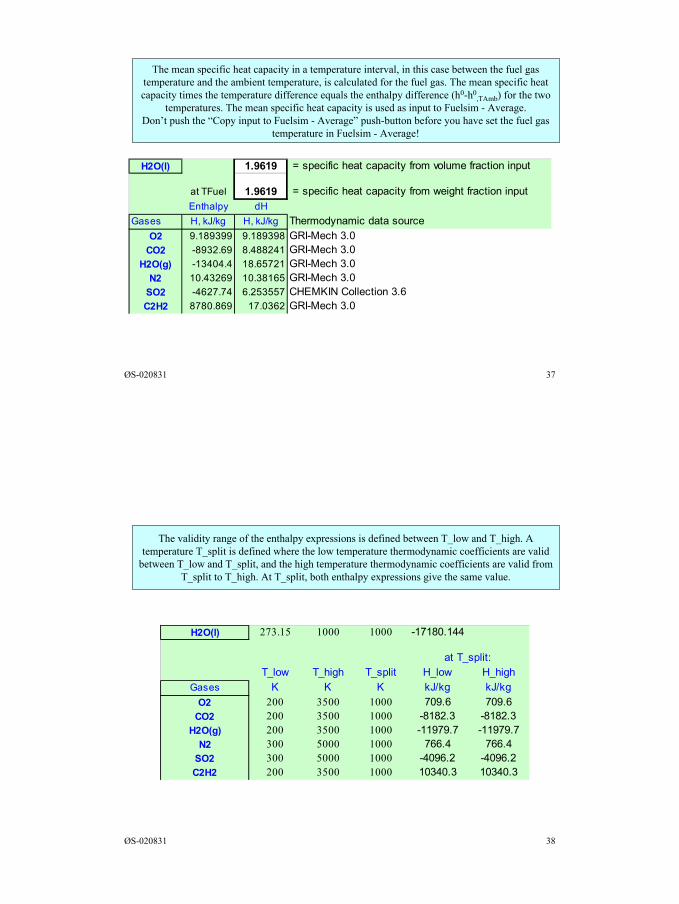
19
ØS-020831 37
The mean specific heat capacity in a temperature interval, in this case between the fuel gastemperature and the ambient temperature, is calculated for the fuel gas. The mean specific heatcapacity times the temperature difference equals the enthalpy difference (h0-h0
,TAmb) for the twotemperatures. The mean specific heat capacity is used as input to Fuelsim - Average.
Don’t push the “Copy input to Fuelsim - Average” push-button before you have set the fuel gastemperature in Fuelsim - Average!
H2O(l) 1.9619 = specific heat capacity from volume fraction input
at TFuel 1.9619 = specific heat capacity from weight fraction inputEnthalpy dH
Gases H, kJ/kg H, kJ/kg Thermodynamic data sourceO2 9.189399 9.189398 GRI-Mech 3.0
CO2 -8932.69 8.488241 GRI-Mech 3.0H2O(g) -13404.4 18.65721 GRI-Mech 3.0
N2 10.43269 10.38165 GRI-Mech 3.0SO2 -4627.74 6.253557 CHEMKIN Collection 3.6C2H2 8780.869 17.0362 GRI-Mech 3.0
ØS-020831 38
The validity range of the enthalpy expressions is defined between T_low and T_high. Atemperature T_split is defined where the low temperature thermodynamic coefficients are valid
between T_low and T_split, and the high temperature thermodynamic coefficients are valid fromT_split to T_high. At T_split, both enthalpy expressions give the same value.
H2O(l) 273.15 1000 1000 -17180.144
at T_split:T_low T_high T_split H_low H_high
Gases K K K kJ/kg kJ/kgO2 200 3500 1000 709.6 709.6
CO2 200 3500 1000 -8182.3 -8182.3H2O(g) 200 3500 1000 -11979.7 -11979.7
N2 300 5000 1000 766.4 766.4SO2 300 5000 1000 -4096.2 -4096.2C2H2 200 3500 1000 10340.3 10340.3
Appendix 4
Fuelsim - Average examples
Øyvind Skreiberg
August 2002
1
ØS-020831 1
Institute of thermal energy and hydropower
Fuelsim - Average v1.1examples
by
Øyvind Skreiberg, Dr.ing.Nordic Senior Research Scientist
Institute of Thermal Energy and Hydropower,Norwegian University of Science and Technology,
N-7491 Trondheime-mail: [email protected]
Documentation for v1.1 of Fuelsim - Average
ØS-020831 2
Contents
Introductory examples, Solid fuel combustion - Page 3
Gas turbine combustion and emission conversion - Page 13
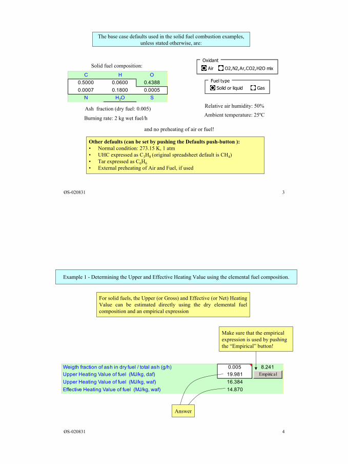
2
ØS-020831 3
The base case defaults used in the solid fuel combustion examples,unless stated otherwise, are:
Other defaults (can be set by pushing the Defaults push-button ):• Normal condition: 273.15 K, 1 atm• UHC expressed as C3H8 (original spreadsheet default is CH4)• Tar expressed as C6H6• External preheating of Air and Fuel, if used
Oxidant
Air O2,N2,Ar,CO2,H2O mixC H O
0.5000 0.0600 0.43880.0007 0.1800 0.0005
N H2O S
Solid fuel composition:
Ash fraction (dry fuel: 0.005) Relative air humidity: 50%
Burning rate: 2 kg wet fuel/h Ambient temperature: 25ºC
and no preheating of air or fuel!
Fuel typeSolid or liquid Gas
ØS-020831 4
Weigth fraction of ash in dry fuel / total ash (g/h) 18.134 0.005 8.241Upper Heating Value of fuel (MJ/kg, daf) 19.992 19.981Upper Heating Value of fuel (MJ/kg, waf) 16.384 35.382Effective Heating Value of fuel (MJ/kg, waf) 14.895 14.870 32.353
Empirical
Example 1 - Determining the Upper and Effective Heating Value using the elemental fuel composition.
For solid fuels, the Upper (or Gross) and Effective (or Net) HeatingValue can be estimated directly using the dry elemental fuelcomposition and an empirical expression
Make sure that the empiricalexpression is used by pushingthe “Empirical” button!
Answer
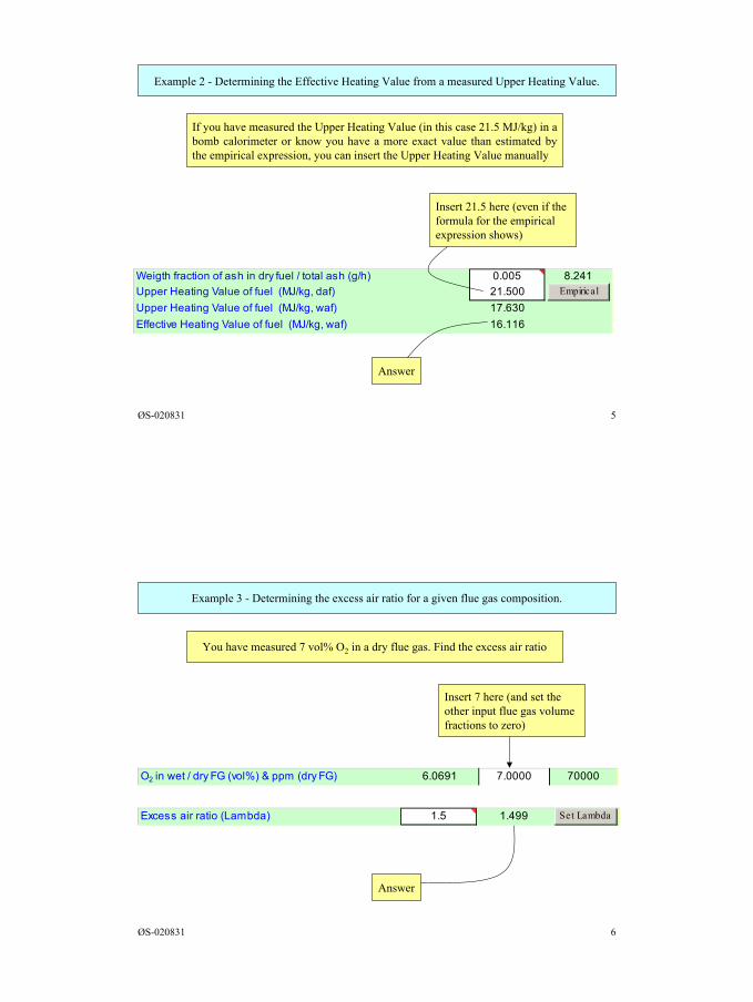
3
ØS-020831 5
Weigth fraction of ash in dry fuel / total ash (g/h) 19.653 0.005 8.241Upper Heating Value of fuel (MJ/kg, daf) 19.992 21.500Upper Heating Value of fuel (MJ/kg, waf) 17.630 37.873Effective Heating Value of fuel (MJ/kg, waf) 16.141 16.116 34.844
Empirical
Example 2 - Determining the Effective Heating Value from a measured Upper Heating Value.
If you have measured the Upper Heating Value (in this case 21.5 MJ/kg) in abomb calorimeter or know you have a more exact value than estimated bythe empirical expression, you can insert the Upper Heating Value manually
Insert 21.5 here (even if theformula for the empiricalexpression shows)
Answer
ØS-020831 6
Example 3 - Determining the excess air ratio for a given flue gas composition.
You have measured 7 vol% O2 in a dry flue gas. Find the excess air ratio
Insert 7 here (and set theother input flue gas volumefractions to zero)
Answer
O2 in wet / dry FG (vol%) & ppm (dry FG) 6.0691 7.0000 70000
Excess air ratio (Lambda) 1.5 1.499 Set Lambda
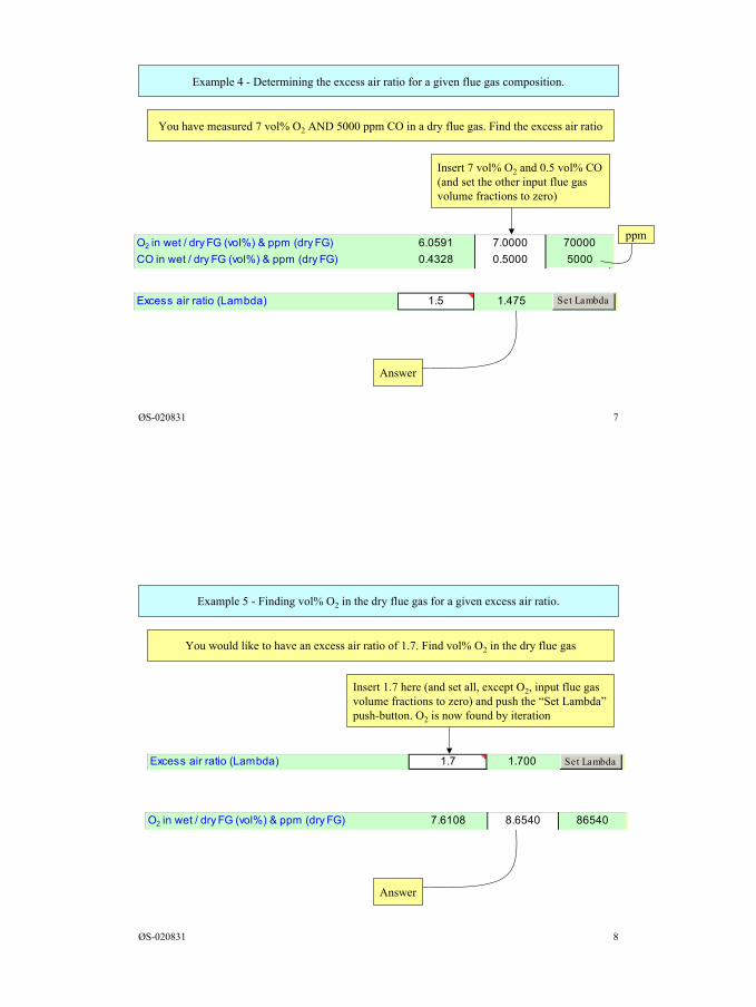
4
ØS-020831 7
Example 4 - Determining the excess air ratio for a given flue gas composition.
You have measured 7 vol% O2 AND 5000 ppm CO in a dry flue gas. Find the excess air ratio
Insert 7 vol% O2 and 0.5 vol% CO(and set the other input flue gasvolume fractions to zero)
Answer
O2 in wet / dry FG (vol%) & ppm (dry FG) 6.0591 7.0000 70000CO in wet / dry FG (vol%) & ppm (dry FG) 0.4328 0.5000 5000
ppm
Excess air ratio (Lambda) 1.5 1.475 Set Lambda
ØS-020831 8
Example 5 - Finding vol% O2 in the dry flue gas for a given excess air ratio.
You would like to have an excess air ratio of 1.7. Find vol% O2 in the dry flue gas
Insert 1.7 here (and set all, except O2, input flue gasvolume fractions to zero) and push the “Set Lambda”push-button. O2 is now found by iteration
Answer
Excess air ratio (Lambda) -4.28546E-14 1.7 1.700 Set Lambda
O2 in wet / dry FG (vol%) & ppm (dry FG) 7.6108 8.6540 86540
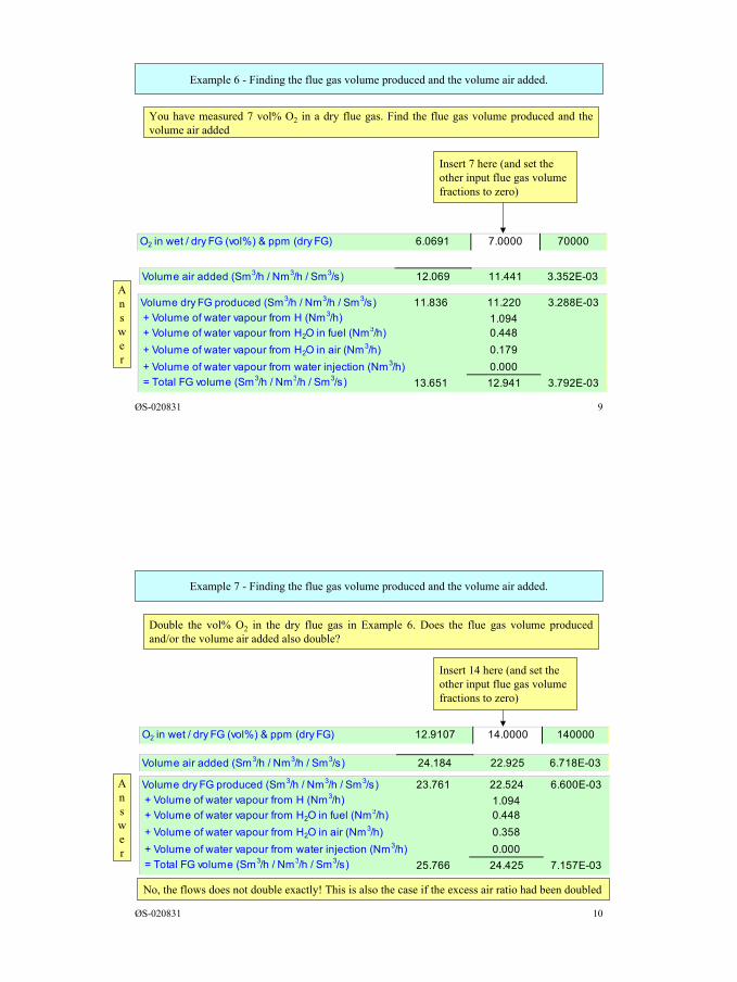
5
ØS-020831 9
Example 6 - Finding the flue gas volume produced and the volume air added.
You have measured 7 vol% O2 in a dry flue gas. Find the flue gas volume produced and thevolume air added
Answer
Insert 7 here (and set theother input flue gas volumefractions to zero)
O2 in wet / dry FG (vol%) & ppm (dry FG) 6.0691 7.0000 70000
Volume air added (Sm3/h / Nm3/h / Sm3/s) 12.069 11.441 3.352E-03
Volume dry FG produced (Sm3/h / Nm3/h / Sm3/s) 11.836 11.220 3.288E-03 + Volume of water vapour from H (Nm3/h) 1.094 + Volume of water vapour from H2O in fuel (Nm3/h) 0.448 + Volume of water vapour from H2O in air (Nm3/h) 0.179 + Volume of water vapour from water injection (Nm3/h) 0.000 = Total FG volume (Sm3/h / Nm3/h / Sm3/s) 13.651 12.941 3.792E-03
ØS-020831 10
Example 7 - Finding the flue gas volume produced and the volume air added.
Double the vol% O2 in the dry flue gas in Example 6. Does the flue gas volume producedand/or the volume air added also double?
Answer
Insert 14 here (and set theother input flue gas volumefractions to zero)
O2 in wet / dry FG (vol%) & ppm (dry FG) 12.9107 14.0000 140000
Volume air added (Sm3/h / Nm3/h / Sm3/s) 24.184 22.925 6.718E-03
No, the flows does not double exactly! This is also the case if the excess air ratio had been doubled
Volume dry FG produced (Sm3/h / Nm3/h / Sm3/s) 23.761 22.524 6.600E-03 + Volume of water vapour from H (Nm3/h) 1.094 + Volume of water vapour from H2O in fuel (Nm3/h) 0.448 + Volume of water vapour from H2O in air (Nm3/h) 0.358 + Volume of water vapour from water injection (Nm3/h) 0.000 = Total FG volume (Sm3/h / Nm3/h / Sm3/s) 25.766 24.425 7.157E-03
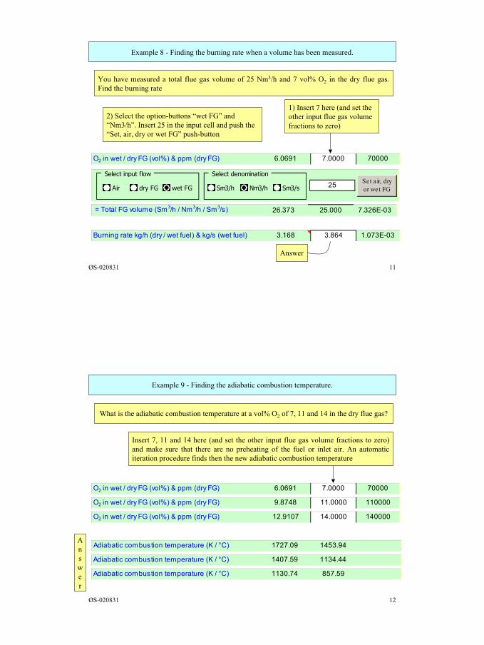
6
ØS-020831 11
Example 8 - Finding the burning rate when a volume has been measured.
You have measured a total flue gas volume of 25 Nm3/h and 7 vol% O2 in the dry flue gas.Find the burning rate
1) Insert 7 here (and set theother input flue gas volumefractions to zero)
O2 in wet / dry FG (vol%) & ppm (dry FG) 6.0691 7.0000 70000
= Total FG volume (Sm3/h / Nm3/h / Sm3/s) 26.373 25.000 7.326E-03
25 Set a ir, dryor wet FG
Select input flow
Air dry FG wet FG
Select denomination
Sm3/h Nm3/h Sm3/s
2) Select the option-buttons “wet FG” and“Nm3/h”. Insert 25 in the input cell and push the“Set, air, dry or wet FG” push-button
Burning rate kg/h (dry / wet fuel) & kg/s (wet fuel) 3.168 3.864 1.073E-03
Answer
ØS-020831 12
Example 9 - Finding the adiabatic combustion temperature.
What is the adiabatic combustion temperature at a vol% O2 of 7, 11 and 14 in the dry flue gas?
Insert 7, 11 and 14 here (and set the other input flue gas volume fractions to zero)and make sure that there are no preheating of the fuel or inlet air. An automaticiteration procedure finds then the new adiabatic combustion temperature
O2 in wet / dry FG (vol%) & ppm (dry FG) 6.0691 7.0000 70000
Answer
O2 in wet / dry FG (vol%) & ppm (dry FG) 9.8748 11.0000 110000
O2 in wet / dry FG (vol%) & ppm (dry FG) 12.9107 14.0000 140000
Adiabatic combustion temperature (K / °C) 1727.09 1453.94
Adiabatic combustion temperature (K / °C) 1407.59 1134.44
Adiabatic combustion temperature (K / °C) 1130.74 857.59
7
ØS-020831 13
Note that ISO 110042-1, Gas turbines - Exhaust gas emission -Part 1: Measurement and evaluation, contains simplifiedexpressions for conversion of emission levels between differentdenominations. Fuelsim - Average is based directly on thecombustion equation, and contains no simplifications whenconverting emission levels between different denominations.
ØS-020831 14
Gas turbine example 1 - LM2500 gas turbine with DLE (low NOx burner).
Problem: 1) Find the NOx emission level in the denominations; a) ppmvd at 15 vol%d O2, b) kg/h,c) g/kWh and d) g/kWhe when:Fuel gas composition (vol%): 1.13N2 + 0.99CO2 + 78.1CH4 + 18.6C2H6 + 1.05C3H8 + 0.1C4H10 +0.01C5H12 + 0.02C6H14Flue gas composition: O2 = 15.38 vol%d, CO = 3.7 ppmvd, UHC (as CH4) = 1.6 ppmvd, CO2 = 3.07vol%d and NOx = 11.5 ppmvwPower output = 18.2 MWBurning rate = 4272 kg/h, Ambient temperature = 25ºC, Relative air humidity = 85 %2) Find NOx in kg/h if you know that the NOx level for this gas turbine is 25 ppmvd at 15 vol%d O2
Solution procedure: 1) The solution is quite straightforward but note that the NOx level in the fluegas is given on wet basis. Also, the power output is calculated on the basis of a combinedturbine/generator el. efficiency, which has to be found. Hence, iterations is needed. The measuredCO2 level is not needed in the calculation, but can be compared with the calculated CO2 level tocheck the measurement accuracy2) The solution can be found by iteration
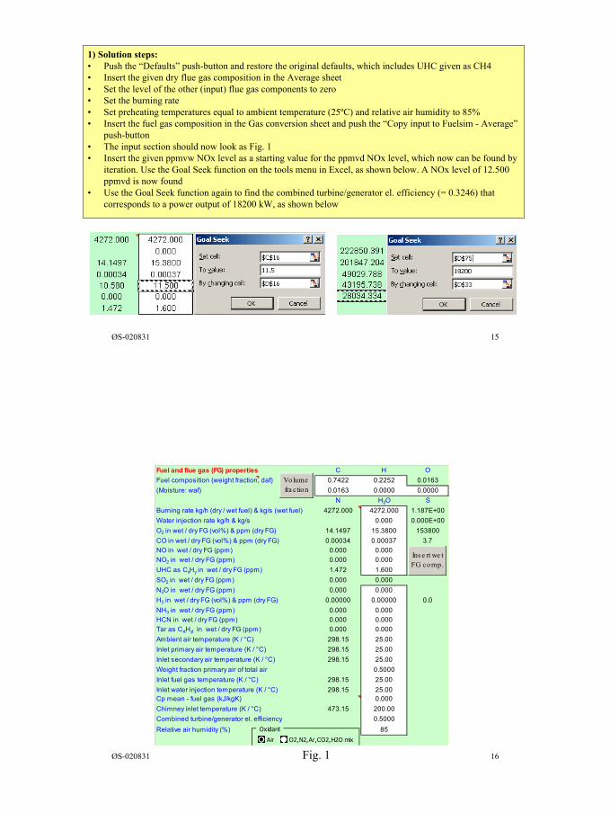
8
ØS-020831 15
1) Solution steps:• Push the “Defaults” push-button and restore the original defaults, which includes UHC given as CH4• Insert the given dry flue gas composition in the Average sheet• Set the level of the other (input) flue gas components to zero• Set the burning rate• Set preheating temperatures equal to ambient temperature (25ºC) and relative air humidity to 85%• Insert the fuel gas composition in the Gas conversion sheet and push the “Copy input to Fuelsim - Average”
push-button• The input section should now look as Fig. 1• Insert the given ppmvw NOx level as a starting value for the ppmvd NOx level, which now can be found by
iteration. Use the Goal Seek function on the tools menu in Excel, as shown below. A NOx level of 12.500ppmvd is now found
• Use the Goal Seek function again to find the combined turbine/generator el. efficiency (= 0.3246) thatcorresponds to a power output of 18200 kW, as shown below
ØS-020831 16Fig. 1
Fuel and flue gas (FG) properties C H OFuel composition (weight fraction, daf) 0.7422 0.2252 0.0163(Moisture: waf) 0.0163 0.0000 0.0000 N H2O SBurning rate kg/h (dry / wet fuel) & kg/s (wet fuel) 4272.000 4272.000 1.187E+00Water injection rate kg/h & kg/s 0.000 0.000E+00O2 in wet / dry FG (vol%) & ppm (dry FG) 14.1497 15.3800 153800CO in wet / dry FG (vol%) & ppm (dry FG) 0.00034 0.00037 3.7NO in wet / dry FG (ppm) 0.000 0.000NO2 in wet / dry FG (ppm) 0.000 0.000UHC as CxHy in wet / dry FG (ppm) 1.472 1.600SO2 in wet / dry FG (ppm) 0.000 0.000N2O in wet / dry FG (ppm) 0.000 0.000H2 in wet / dry FG (vol%) & ppm (dry FG) 0.00000 0.00000 0.0NH3 in wet / dry FG (ppm) 0.000 0.000HCN in wet / dry FG (ppm) 0.000 0.000Tar as CxtHyt in wet / dry FG (ppm) 0.000 0.000Ambient air temperature (K / °C) 298.15 25.00Inlet primary air temperature (K / °C) 298.15 25.00Inlet secondary air temperature (K / °C) 298.15 25.00Weight fraction primary air of total air 0.5000Inlet fuel gas temperature (K / °C) 298.15 25.00 Inlet water injection temperature (K / °C) 298.15 25.00 Cp mean - fuel gas (kJ/kgK) 0.000Chimney inlet temperature (K / °C) 473.15 200.00Combined turbine/generator el. efficiency 0.5000Relative air humidity (%) 85
Ins e rt we t FG comp.
Volume fra ction
Oxidant
Air O2,N2,Ar,CO2,H2O mix
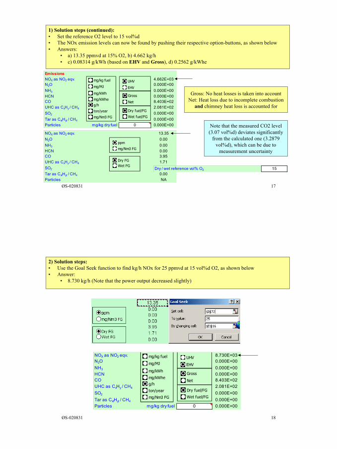
9
ØS-020831 17
1) Solution steps (continued):• Set the reference O2 level to 15 vol%d• The NOx emission levels can now be found by pushing their respective option-buttons, as shown below• Answers:
• a) 13.35 ppmvd at 15% O2, b) 4.662 kg/h• c) 0.08314 g/kWh (based on EHV and Gross), d) 0.2562 g/kWhe
NOX as NO2 eqv. 13.35N2O 0.00NH3 0.00HCN 0.00CO 3.95UHC as CxHy / CH4 1.71SO2 0.00Tar as CxtHyt / CH4 0.00Particles NA
Dry FGWet FG
ppm
mg/Nm3 FG
EmissionsNOX as NO2 eqv. 4.662E+03N2O 0.000E+00NH3 0.000E+00HCN 0.000E+00CO 8.403E+02UHC as CxHy / CH4 2.081E+02SO2 0.000E+00Tar as CxtHyt / CH4 0.000E+00Particles mg/kg dry fuel 0 0.000E+00
mg/kg fuel
mg/MJ
mg/kWh
g/h
ton/year
UHV
EHV
mg/Nm3 FG
Dry fuel/FG
Wet fuel/FG
Gross
Netmg/kWhe
Gross: No heat losses is taken into accountNet: Heat loss due to incomplete combustion
and chimney heat loss is accounted for
Dry / wet reference vol% O2 15
Note that the measured CO2 level(3.07 vol%d) deviates significantly
from the calculated one (3.2879vol%d), which can be due to
measurement uncertainty
ØS-020831 18
2) Solution steps:• Use the Goal Seek function to find kg/h NOx for 25 ppmvd at 15 vol%d O2, as shown below• Answer:
• 8.730 kg/h (Note that the power output decreased slightly)
NOX as NO2 eqv. 8.730E+03N2O 0.000E+00NH3 0.000E+00HCN 0.000E+00CO 8.403E+02UHC as CxHy / CH4 2.081E+02SO2 0.000E+00Tar as CxtHyt / CH4 0.000E+00Particles mg/kg dry fuel 0 0.000E+00
mg/kg fuel
mg/MJ
mg/kWh
g/h
ton/year
UHV
EHV
mg/Nm3 FG
Dry fuel/FG
Wet fuel/FG
Gross
Netmg/kWhe
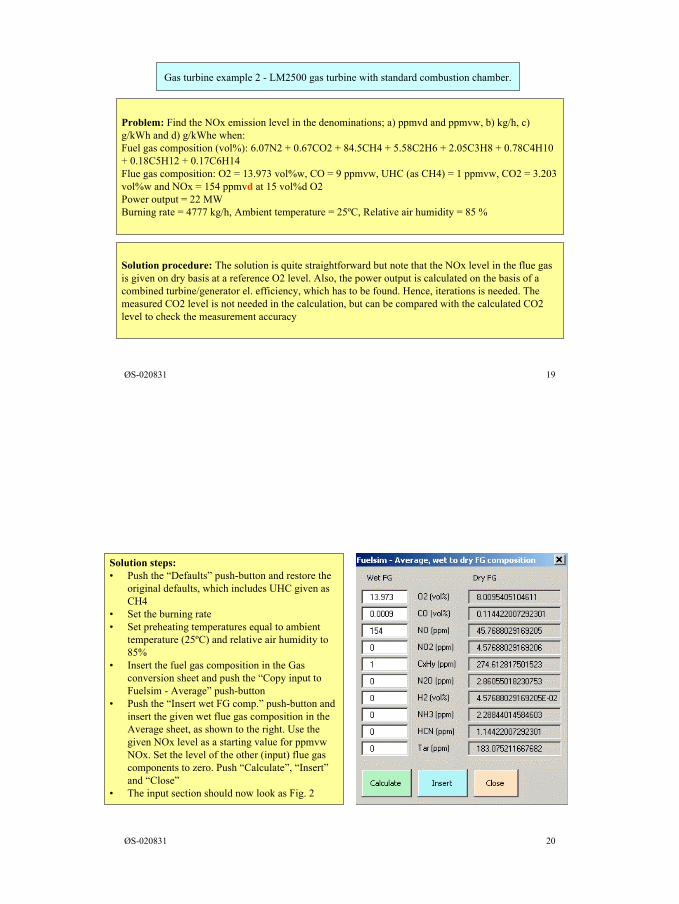
10
ØS-020831 19
Gas turbine example 2 - LM2500 gas turbine with standard combustion chamber.
Problem: Find the NOx emission level in the denominations; a) ppmvd and ppmvw, b) kg/h, c)g/kWh and d) g/kWhe when:Fuel gas composition (vol%): 6.07N2 + 0.67CO2 + 84.5CH4 + 5.58C2H6 + 2.05C3H8 + 0.78C4H10+ 0.18C5H12 + 0.17C6H14Flue gas composition: O2 = 13.973 vol%w, CO = 9 ppmvw, UHC (as CH4) = 1 ppmvw, CO2 = 3.203vol%w and NOx = 154 ppmvd at 15 vol%d O2Power output = 22 MWBurning rate = 4777 kg/h, Ambient temperature = 25ºC, Relative air humidity = 85 %
Solution procedure: The solution is quite straightforward but note that the NOx level in the flue gasis given on dry basis at a reference O2 level. Also, the power output is calculated on the basis of acombined turbine/generator el. efficiency, which has to be found. Hence, iterations is needed. Themeasured CO2 level is not needed in the calculation, but can be compared with the calculated CO2level to check the measurement accuracy
ØS-020831 20
Solution steps:• Push the “Defaults” push-button and restore the
original defaults, which includes UHC given asCH4
• Set the burning rate• Set preheating temperatures equal to ambient
temperature (25ºC) and relative air humidity to85%
• Insert the fuel gas composition in the Gasconversion sheet and push the “Copy input toFuelsim - Average” push-button
• Push the “Insert wet FG comp.” push-button andinsert the given wet flue gas composition in theAverage sheet, as shown to the right. Use thegiven NOx level as a starting value for ppmvwNOx. Set the level of the other (input) flue gascomponents to zero. Push “Calculate”, “Insert”and “Close”
• The input section should now look as Fig. 2
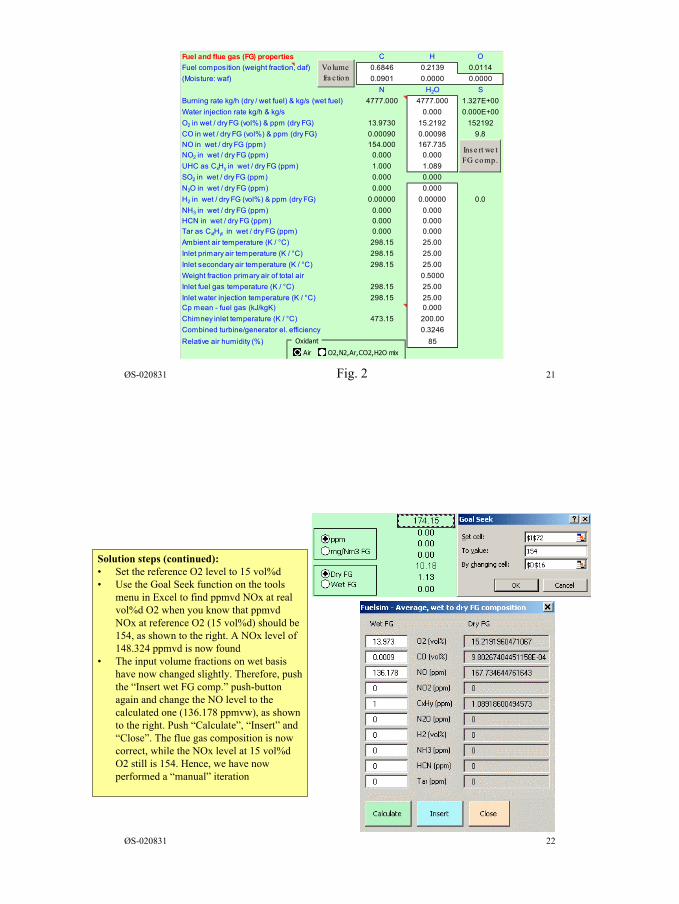
11
ØS-020831 21Fig. 2
Fuel and flue gas (FG) properties C H OFuel composition (weight fraction, daf) 0.6846 0.2139 0.0114(Moisture: waf) 0.0901 0.0000 0.0000 N H2O SBurning rate kg/h (dry / wet fuel) & kg/s (wet fuel) 4777.000 4777.000 1.327E+00Water injection rate kg/h & kg/s 0.000 0.000E+00O2 in wet / dry FG (vol%) & ppm (dry FG) 13.9730 15.2192 152192CO in wet / dry FG (vol%) & ppm (dry FG) 0.00090 0.00098 9.8NO in wet / dry FG (ppm) 154.000 167.735NO2 in wet / dry FG (ppm) 0.000 0.000UHC as CxHy in wet / dry FG (ppm) 1.000 1.089SO2 in wet / dry FG (ppm) 0.000 0.000N2O in wet / dry FG (ppm) 0.000 0.000H2 in wet / dry FG (vol%) & ppm (dry FG) 0.00000 0.00000 0.0NH3 in wet / dry FG (ppm) 0.000 0.000HCN in wet / dry FG (ppm) 0.000 0.000Tar as CxtHyt in wet / dry FG (ppm) 0.000 0.000Ambient air temperature (K / °C) 298.15 25.00Inlet primary air temperature (K / °C) 298.15 25.00Inlet secondary air temperature (K / °C) 298.15 25.00Weight fraction primary air of total air 0.5000Inlet fuel gas temperature (K / °C) 298.15 25.00 Inlet water injection temperature (K / °C) 298.15 25.00 Cp mean - fuel gas (kJ/kgK) 0.000Chimney inlet temperature (K / °C) 473.15 200.00Combined turbine/generator el. efficiency 0.3246Relative air humidity (%) 85
Ins e rt we t FG comp.
Volume fra ction
Oxidant
Air O2,N2,Ar,CO2,H2O mix
ØS-020831 22
Solution steps (continued):• Set the reference O2 level to 15 vol%d• Use the Goal Seek function on the tools
menu in Excel to find ppmvd NOx at realvol%d O2 when you know that ppmvdNOx at reference O2 (15 vol%d) should be154, as shown to the right. A NOx level of148.324 ppmvd is now found
• The input volume fractions on wet basishave now changed slightly. Therefore, pushthe “Insert wet FG comp.” push-buttonagain and change the NO level to thecalculated one (136.178 ppmvw), as shownto the right. Push “Calculate”, “Insert” and“Close”. The flue gas composition is nowcorrect, while the NOx level at 15 vol%dO2 still is 154. Hence, we have nowperformed a “manual” iteration
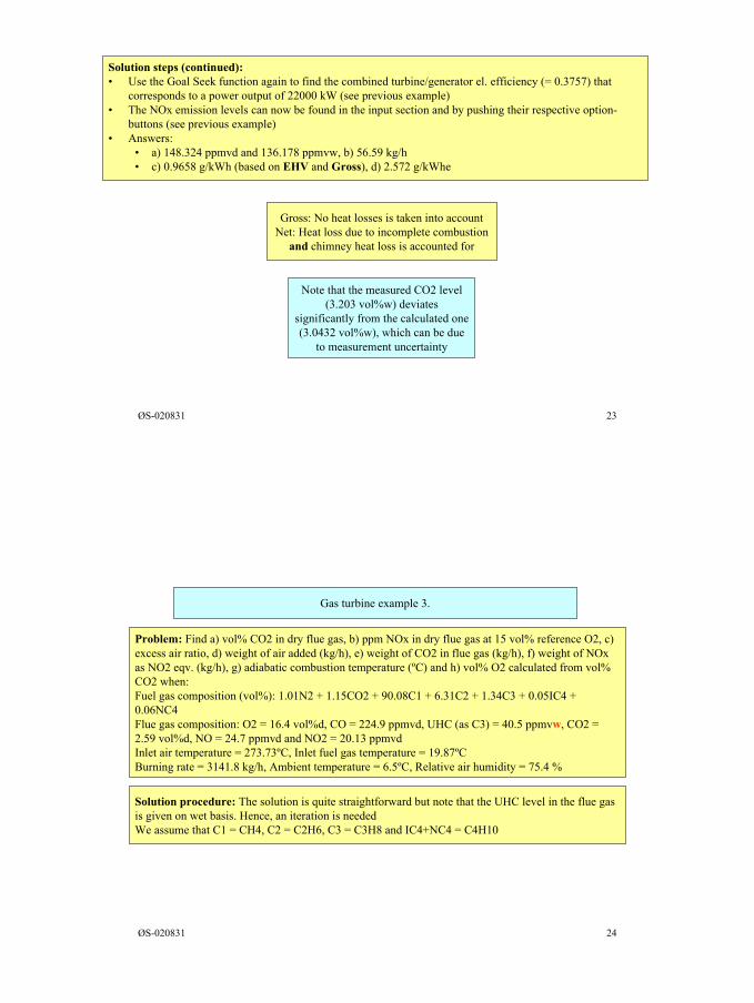
12
ØS-020831 23
Solution steps (continued):• Use the Goal Seek function again to find the combined turbine/generator el. efficiency (= 0.3757) that
corresponds to a power output of 22000 kW (see previous example)• The NOx emission levels can now be found in the input section and by pushing their respective option-
buttons (see previous example)• Answers:
• a) 148.324 ppmvd and 136.178 ppmvw, b) 56.59 kg/h• c) 0.9658 g/kWh (based on EHV and Gross), d) 2.572 g/kWhe
Gross: No heat losses is taken into accountNet: Heat loss due to incomplete combustion
and chimney heat loss is accounted for
Note that the measured CO2 level(3.203 vol%w) deviates
significantly from the calculated one(3.0432 vol%w), which can be due
to measurement uncertainty
ØS-020831 24
Gas turbine example 3.
Problem: Find a) vol% CO2 in dry flue gas, b) ppm NOx in dry flue gas at 15 vol% reference O2, c)excess air ratio, d) weight of air added (kg/h), e) weight of CO2 in flue gas (kg/h), f) weight of NOxas NO2 eqv. (kg/h), g) adiabatic combustion temperature (ºC) and h) vol% O2 calculated from vol%CO2 when:Fuel gas composition (vol%): 1.01N2 + 1.15CO2 + 90.08C1 + 6.31C2 + 1.34C3 + 0.05IC4 +0.06NC4Flue gas composition: O2 = 16.4 vol%d, CO = 224.9 ppmvd, UHC (as C3) = 40.5 ppmvw, CO2 =2.59 vol%d, NO = 24.7 ppmvd and NO2 = 20.13 ppmvdInlet air temperature = 273.73ºC, Inlet fuel gas temperature = 19.87ºCBurning rate = 3141.8 kg/h, Ambient temperature = 6.5ºC, Relative air humidity = 75.4 %
Solution procedure: The solution is quite straightforward but note that the UHC level in the flue gasis given on wet basis. Hence, an iteration is neededWe assume that C1 = CH4, C2 = C2H6, C3 = C3H8 and IC4+NC4 = C4H10
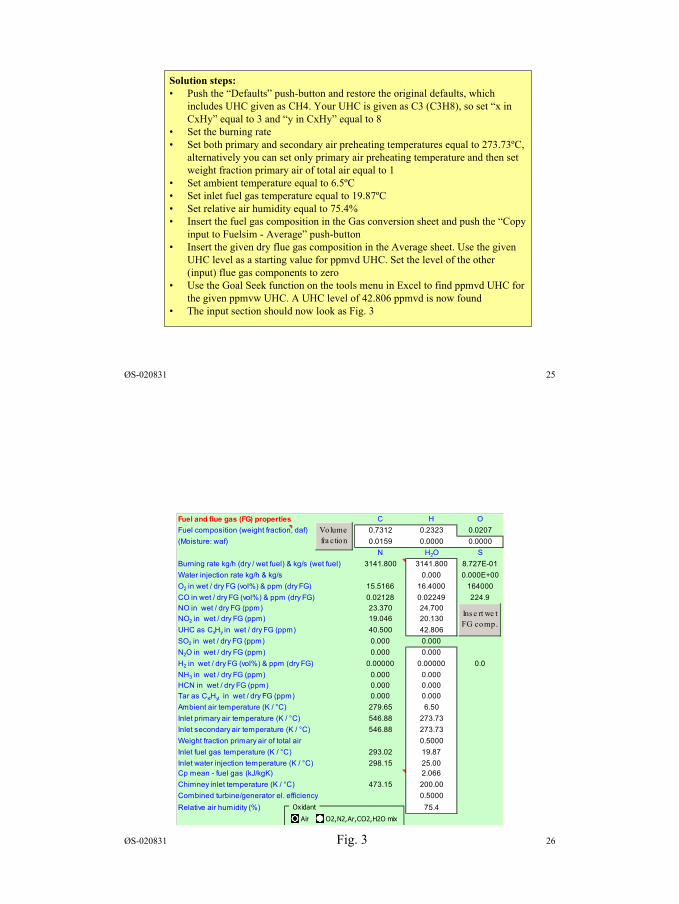
13
ØS-020831 25
Solution steps:• Push the “Defaults” push-button and restore the original defaults, which
includes UHC given as CH4. Your UHC is given as C3 (C3H8), so set “x inCxHy” equal to 3 and “y in CxHy” equal to 8
• Set the burning rate• Set both primary and secondary air preheating temperatures equal to 273.73ºC,
alternatively you can set only primary air preheating temperature and then setweight fraction primary air of total air equal to 1
• Set ambient temperature equal to 6.5ºC• Set inlet fuel gas temperature equal to 19.87ºC• Set relative air humidity equal to 75.4%• Insert the fuel gas composition in the Gas conversion sheet and push the “Copy
input to Fuelsim - Average” push-button• Insert the given dry flue gas composition in the Average sheet. Use the given
UHC level as a starting value for ppmvd UHC. Set the level of the other(input) flue gas components to zero
• Use the Goal Seek function on the tools menu in Excel to find ppmvd UHC forthe given ppmvw UHC. A UHC level of 42.806 ppmvd is now found
• The input section should now look as Fig. 3
ØS-020831 26Fig. 3
Fuel and flue gas (FG) properties C H OFuel composition (weight fraction, daf) 0.7312 0.2323 0.0207(Moisture: waf) 0.0159 0.0000 0.0000 N H2O SBurning rate kg/h (dry / wet fuel) & kg/s (wet fuel) 3141.800 3141.800 8.727E-01Water injection rate kg/h & kg/s 0.000 0.000E+00O2 in wet / dry FG (vol%) & ppm (dry FG) 15.5166 16.4000 164000CO in wet / dry FG (vol%) & ppm (dry FG) 0.02128 0.02249 224.9NO in wet / dry FG (ppm) 23.370 24.700NO2 in wet / dry FG (ppm) 19.046 20.130UHC as CxHy in wet / dry FG (ppm) 40.500 42.806SO2 in wet / dry FG (ppm) 0.000 0.000N2O in wet / dry FG (ppm) 0.000 0.000H2 in wet / dry FG (vol%) & ppm (dry FG) 0.00000 0.00000 0.0NH3 in wet / dry FG (ppm) 0.000 0.000HCN in wet / dry FG (ppm) 0.000 0.000Tar as CxtHyt in wet / dry FG (ppm) 0.000 0.000Ambient air temperature (K / °C) 279.65 6.50Inlet primary air temperature (K / °C) 546.88 273.73Inlet secondary air temperature (K / °C) 546.88 273.73Weight fraction primary air of total air 0.5000Inlet fuel gas temperature (K / °C) 293.02 19.87 Inlet water injection temperature (K / °C) 298.15 25.00 Cp mean - fuel gas (kJ/kgK) 2.066Chimney inlet temperature (K / °C) 473.15 200.00Combined turbine/generator el. efficiency 0.5000Relative air humidity (%) 75.4
Ins e rt we t FG comp.
Volume fra ction
Oxidant
Air O2,N2,Ar,CO2,H2O mix
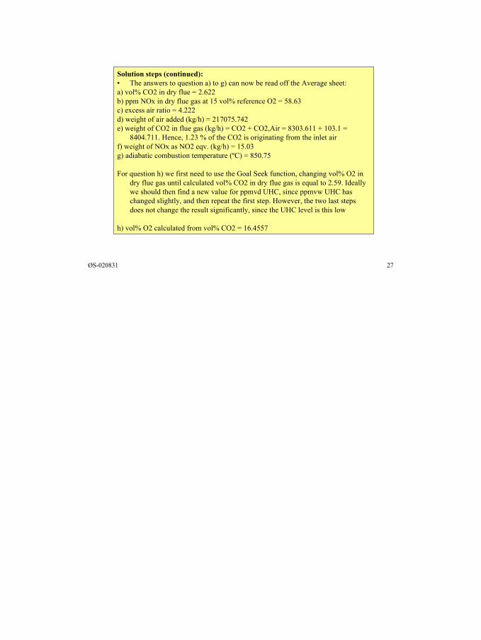
14
ØS-020831 27
Solution steps (continued):• The answers to question a) to g) can now be read off the Average sheet:a) vol% CO2 in dry flue = 2.622b) ppm NOx in dry flue gas at 15 vol% reference O2 = 58.63c) excess air ratio = 4.222d) weight of air added (kg/h) = 217075.742e) weight of CO2 in flue gas (kg/h) = CO2 + CO2,Air = 8303.611 + 103.1 =
8404.711. Hence, 1.23 % of the CO2 is originating from the inlet airf) weight of NOx as NO2 eqv. (kg/h) = 15.03g) adiabatic combustion temperature (ºC) = 850.75
For question h) we first need to use the Goal Seek function, changing vol% O2 indry flue gas until calculated vol% CO2 in dry flue gas is equal to 2.59. Ideallywe should then find a new value for ppmvd UHC, since ppmvw UHC haschanged slightly, and then repeat the first step. However, the two last stepsdoes not change the result significantly, since the UHC level is this low
h) vol% O2 calculated from vol% CO2 = 16.4557
Appendix 5
Fuelsim - Average exercise
Øyvind Skreiberg
August 2002
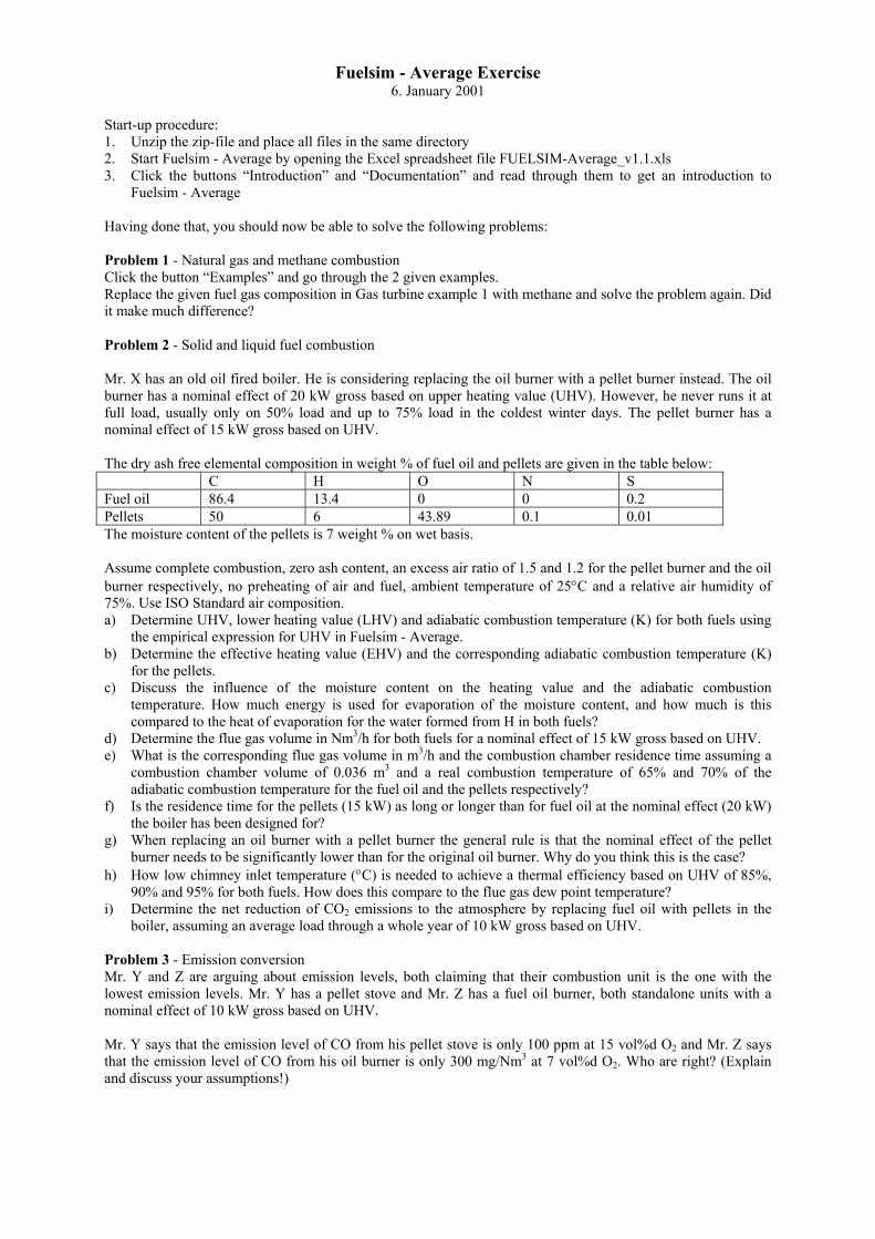
Fuelsim - Average Exercise6. January 2001
Start-up procedure:1. Unzip the zip-file and place all files in the same directory2. Start Fuelsim - Average by opening the Excel spreadsheet file FUELSIM-Average_v1.1.xls3. Click the buttons “Introduction” and “Documentation” and read through them to get an introduction to
Fuelsim - Average
Having done that, you should now be able to solve the following problems:
Problem 1 - Natural gas and methane combustionClick the button “Examples” and go through the 2 given examples.Replace the given fuel gas composition in Gas turbine example 1 with methane and solve the problem again. Didit make much difference?
Problem 2 - Solid and liquid fuel combustion
Mr. X has an old oil fired boiler. He is considering replacing the oil burner with a pellet burner instead. The oilburner has a nominal effect of 20 kW gross based on upper heating value (UHV). However, he never runs it atfull load, usually only on 50% load and up to 75% load in the coldest winter days. The pellet burner has anominal effect of 15 kW gross based on UHV.
The dry ash free elemental composition in weight % of fuel oil and pellets are given in the table below:C H O N S
Fuel oil 86.4 13.4 0 0 0.2Pellets 50 6 43.89 0.1 0.01The moisture content of the pellets is 7 weight % on wet basis.
Assume complete combustion, zero ash content, an excess air ratio of 1.5 and 1.2 for the pellet burner and the oilburner respectively, no preheating of air and fuel, ambient temperature of 25°C and a relative air humidity of75%. Use ISO Standard air composition.a) Determine UHV, lower heating value (LHV) and adiabatic combustion temperature (K) for both fuels using
the empirical expression for UHV in Fuelsim - Average.b) Determine the effective heating value (EHV) and the corresponding adiabatic combustion temperature (K)
for the pellets.c) Discuss the influence of the moisture content on the heating value and the adiabatic combustion
temperature. How much energy is used for evaporation of the moisture content, and how much is thiscompared to the heat of evaporation for the water formed from H in both fuels?
d) Determine the flue gas volume in Nm3/h for both fuels for a nominal effect of 15 kW gross based on UHV.e) What is the corresponding flue gas volume in m3/h and the combustion chamber residence time assuming a
combustion chamber volume of 0.036 m3 and a real combustion temperature of 65% and 70% of theadiabatic combustion temperature for the fuel oil and the pellets respectively?
f) Is the residence time for the pellets (15 kW) as long or longer than for fuel oil at the nominal effect (20 kW)the boiler has been designed for?
g) When replacing an oil burner with a pellet burner the general rule is that the nominal effect of the pelletburner needs to be significantly lower than for the original oil burner. Why do you think this is the case?
h) How low chimney inlet temperature (°C) is needed to achieve a thermal efficiency based on UHV of 85%,90% and 95% for both fuels. How does this compare to the flue gas dew point temperature?
i) Determine the net reduction of CO2 emissions to the atmosphere by replacing fuel oil with pellets in theboiler, assuming an average load through a whole year of 10 kW gross based on UHV.
Problem 3 - Emission conversionMr. Y and Z are arguing about emission levels, both claiming that their combustion unit is the one with thelowest emission levels. Mr. Y has a pellet stove and Mr. Z has a fuel oil burner, both standalone units with anominal effect of 10 kW gross based on UHV.
Mr. Y says that the emission level of CO from his pellet stove is only 100 ppm at 15 vol%d O2 and Mr. Z saysthat the emission level of CO from his oil burner is only 300 mg/Nm3 at 7 vol%d O2. Who are right? (Explainand discuss your assumptions!)
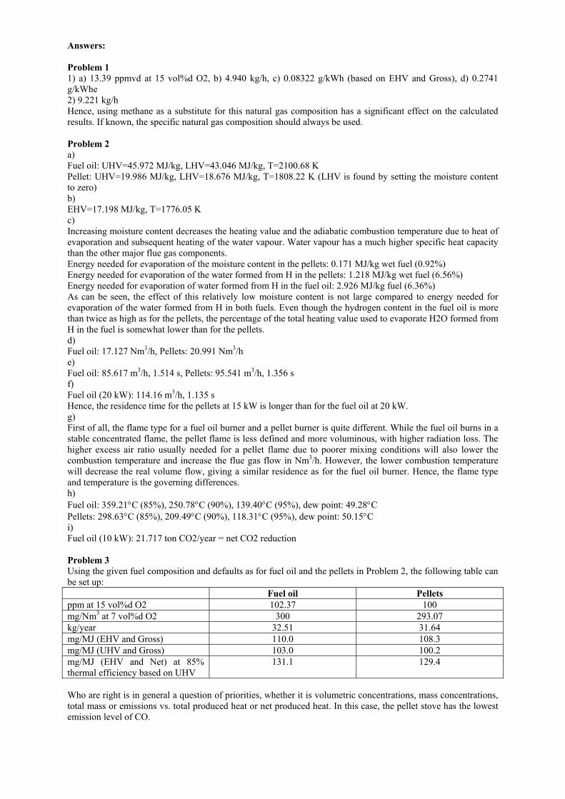
Answers:
Problem 11) a) 13.39 ppmvd at 15 vol%d O2, b) 4.940 kg/h, c) 0.08322 g/kWh (based on EHV and Gross), d) 0.2741g/kWhe2) 9.221 kg/hHence, using methane as a substitute for this natural gas composition has a significant effect on the calculatedresults. If known, the specific natural gas composition should always be used.
Problem 2a)Fuel oil: UHV=45.972 MJ/kg, LHV=43.046 MJ/kg, T=2100.68 KPellet: UHV=19.986 MJ/kg, LHV=18.676 MJ/kg, T=1808.22 K (LHV is found by setting the moisture contentto zero)b)EHV=17.198 MJ/kg, T=1776.05 Kc)Increasing moisture content decreases the heating value and the adiabatic combustion temperature due to heat ofevaporation and subsequent heating of the water vapour. Water vapour has a much higher specific heat capacitythan the other major flue gas components.Energy needed for evaporation of the moisture content in the pellets: 0.171 MJ/kg wet fuel (0.92%)Energy needed for evaporation of the water formed from H in the pellets: 1.218 MJ/kg wet fuel (6.56%)Energy needed for evaporation of water formed from H in the fuel oil: 2.926 MJ/kg fuel (6.36%)As can be seen, the effect of this relatively low moisture content is not large compared to energy needed forevaporation of the water formed from H in both fuels. Even though the hydrogen content in the fuel oil is morethan twice as high as for the pellets, the percentage of the total heating value used to evaporate H2O formed fromH in the fuel is somewhat lower than for the pellets.d)Fuel oil: 17.127 Nm3/h, Pellets: 20.991 Nm3/he)Fuel oil: 85.617 m3/h, 1.514 s, Pellets: 95.541 m3/h, 1.356 sf)Fuel oil (20 kW): 114.16 m3/h, 1.135 sHence, the residence time for the pellets at 15 kW is longer than for the fuel oil at 20 kW.g)First of all, the flame type for a fuel oil burner and a pellet burner is quite different. While the fuel oil burns in astable concentrated flame, the pellet flame is less defined and more voluminous, with higher radiation loss. Thehigher excess air ratio usually needed for a pellet flame due to poorer mixing conditions will also lower thecombustion temperature and increase the flue gas flow in Nm3/h. However, the lower combustion temperaturewill decrease the real volume flow, giving a similar residence as for the fuel oil burner. Hence, the flame typeand temperature is the governing differences.h)Fuel oil: 359.21°C (85%), 250.78°C (90%), 139.40°C (95%), dew point: 49.28°CPellets: 298.63°C (85%), 209.49°C (90%), 118.31°C (95%), dew point: 50.15°Ci)Fuel oil (10 kW): 21.717 ton CO2/year = net CO2 reduction
Problem 3Using the given fuel composition and defaults as for fuel oil and the pellets in Problem 2, the following table canbe set up:
Fuel oil Pelletsppm at 15 vol%d O2 102.37 100mg/Nm3 at 7 vol%d O2 300 293.07kg/year 32.51 31.64mg/MJ (EHV and Gross) 110.0 108.3mg/MJ (UHV and Gross) 103.0 100.2mg/MJ (EHV and Net) at 85%thermal efficiency based on UHV
131.1 129.4
Who are right is in general a question of priorities, whether it is volumetric concentrations, mass concentrations,total mass or emissions vs. total produced heat or net produced heat. In this case, the pellet stove has the lowestemission level of CO.
Appendix 6
Fuelsim - Average versus ISO 11042-1
Øyvind Skreiberg
August 2002
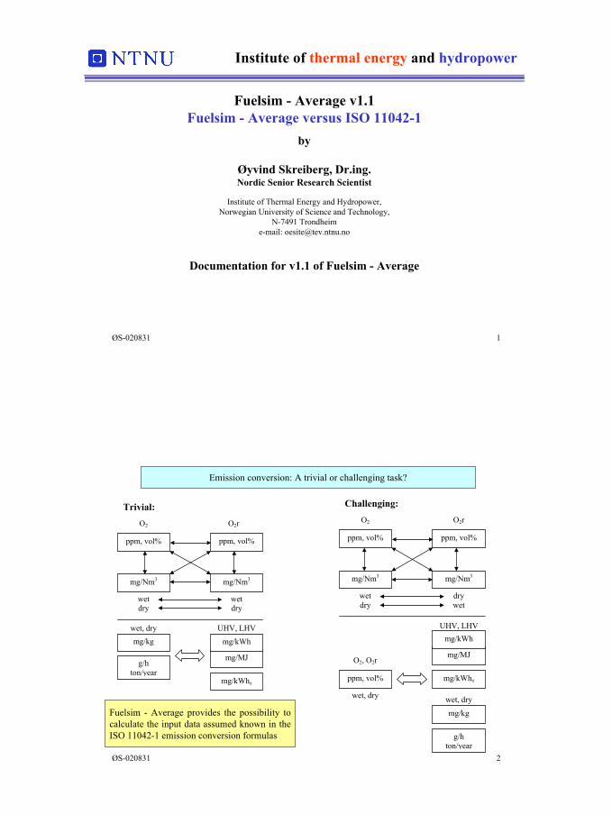
1
ØS-020831 1
Institute of thermal energy and hydropower
Fuelsim - Average v1.1Fuelsim - Average versus ISO 11042-1
by
Øyvind Skreiberg, Dr.ing.Nordic Senior Research Scientist
Institute of Thermal Energy and Hydropower,Norwegian University of Science and Technology,
N-7491 Trondheime-mail: [email protected]
Documentation for v1.1 of Fuelsim - Average
ØS-020831 2
Emission conversion: A trivial or challenging task?
mg/kWhe
wet, dry
mg/MJ
UHV, LHV
mg/kWh
wetdry
O2
ppm, vol%
wetdry
O2r
mg/Nm3
mg/kg
mg/Nm3
ppm, vol%
g/hton/year
Trivial:
wet, dry
O2, O2r
ppm, vol% mg/kWhe
mg/MJ
UHV, LHVmg/kWh
wet, dry
mg/kg
wetdry
O2
ppm, vol%
drywet
O2r
mg/Nm3mg/Nm3
ppm, vol%
g/hton/year
Challenging:
Fuelsim - Average provides the possibility tocalculate the input data assumed known in theISO 11042-1 emission conversion formulas
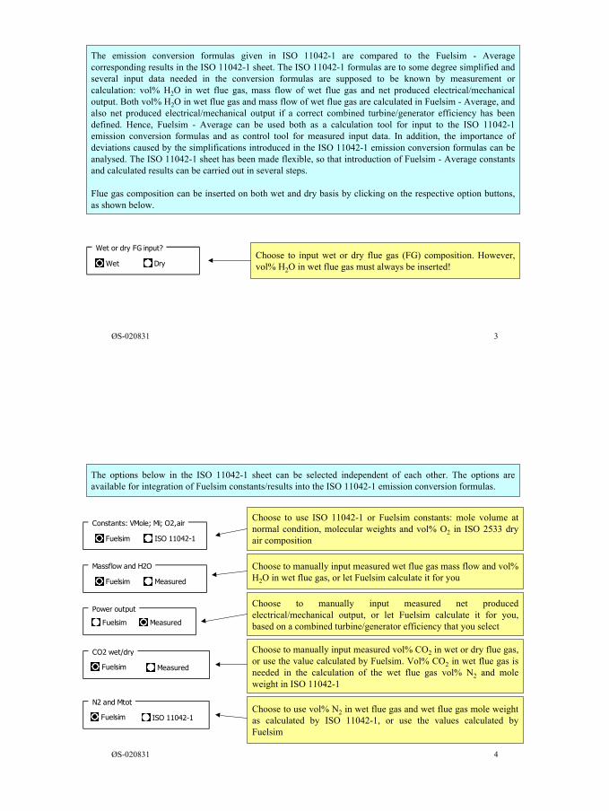
2
ØS-020831 3
The emission conversion formulas given in ISO 11042-1 are compared to the Fuelsim - Averagecorresponding results in the ISO 11042-1 sheet. The ISO 11042-1 formulas are to some degree simplified andseveral input data needed in the conversion formulas are supposed to be known by measurement orcalculation: vol% H2O in wet flue gas, mass flow of wet flue gas and net produced electrical/mechanicaloutput. Both vol% H2O in wet flue gas and mass flow of wet flue gas are calculated in Fuelsim - Average, andalso net produced electrical/mechanical output if a correct combined turbine/generator efficiency has beendefined. Hence, Fuelsim - Average can be used both as a calculation tool for input to the ISO 11042-1emission conversion formulas and as control tool for measured input data. In addition, the importance ofdeviations caused by the simplifications introduced in the ISO 11042-1 emission conversion formulas can beanalysed. The ISO 11042-1 sheet has been made flexible, so that introduction of Fuelsim - Average constantsand calculated results can be carried out in several steps.
Flue gas composition can be inserted on both wet and dry basis by clicking on the respective option buttons,as shown below.
Wet or dry FG input?
Wet DryChoose to input wet or dry flue gas (FG) composition. However,vol% H2O in wet flue gas must always be inserted!
ØS-020831 4
Constants: VMole; Mi; O2,air
Fuelsim ISO 11042-1
Massflow and H2O
Fuelsim Measured
Choose to use ISO 11042-1 or Fuelsim constants: mole volume atnormal condition, molecular weights and vol% O2 in ISO 2533 dryair composition
Choose to manually input measured wet flue gas mass flow and vol%H2O in wet flue gas, or let Fuelsim calculate it for you
Choose to manually input measured net producedelectrical/mechanical output, or let Fuelsim calculate it for you,based on a combined turbine/generator efficiency that you select
Choose to manually input measured vol% CO2 in wet or dry flue gas,or use the value calculated by Fuelsim. Vol% CO2 in wet flue gas isneeded in the calculation of the wet flue gas vol% N2 and moleweight in ISO 11042-1
The options below in the ISO 11042-1 sheet can be selected independent of each other. The options areavailable for integration of Fuelsim constants/results into the ISO 11042-1 emission conversion formulas.
N2 and Mtot
Fuelsim ISO 11042-1Choose to use vol% N2 in wet flue gas and wet flue gas mole weightas calculated by ISO 11042-1, or use the values calculated byFuelsim
Power output
Fuelsim Measured
CO2 wet/dry
Fuelsim Measured
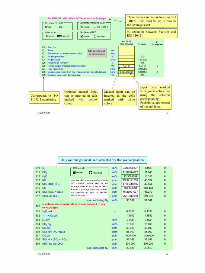
3
ØS-020831 5
Corresponds to ISO11042-1 numbering
Optional manual inputcan be inserted in cellsmarked with yellowcolour
Manual input can beinserted in the cellsmarked with whitecolour
Input cells markedwith green colour areusing the selectedcorrespondingFuelsim values insteadof manual input
Set N2O, H2, NH3, HCN and Tar as zero in Average!
wet inputISO 11042-1 Fuelsim %deviation
200 Test No.201 Time min202 Time taken to measure one point min203 Air temperature °C 100204 Air pressure kPa 101.325205 Relative air humidity % 50206 Power output (mechanical/electrical) kW 4.0147 4.0147 0207 Fuel mass flow kg/s 0.00056208 Exhaus gas mass flow (by measurement or calculation) kg/s 0.004537358 0.00454 0209 Exhaust gas mean temperature °C 200
Wet or dry FG input?
Wet Dry
Constants: VMole; Mi; O2,air
Fuelsim ISO 11042-1
Massflow and H2O
Fuelsim Measured
Power output
Fuelsim Measured
Introduction a nd docume nta tion
These species are not included in ISO11042-1, and must be set to zero inthe Average sheet
% deviation between Fuelsim andISO 11042-1
ØS-020831 6
Only wet flue gas input, and calculated dry flue gas composition.
210 O2 vol% 6.065068107 6.065 0211 CO2 vol% 11.84344697 11.843 0212 H2O vol% 13.3561699 13.356 0213 NO ppm 43.32191505 43.322 0214 NOx (NO+NO2) ppm 47.65410655 47.654 0215 CO ppm 866.438301 866.438 0216 SOx (SO2 + SO3) ppm 45.26991037 45.270 0217 UHC (as CH4) ppm 259.9314903 259.931 0
sum, excluding N2 vol% 31.387 31.387
300 = Volumetric concentration of component i in dry exhaust gas
301 H2O,wet - 0.1336 0.1336 0302 1/(1-H2O,wet) - 1.1542 1.1542 0303 O2,dry vol% 7.000 7.000 0304 CO2,dry vol% 13.669 13.669 0305 NO,dry ppm 50.000 50.000 0306 NOx,dry (NO+NO2) ppm 55.000 55.000 0307 CO,dry ppm 1000.000 1000.000 0308 SOx,dry (SO2 + SO3) ppm 52.248 52.248 0309 UHC,dry (as CH4) ppm 300.000 300.000 0
sum, excluding N2 vol% 20.810 20.810
CO2 wet/dry
Fuelsim Measured
Note that UHC is expressed as CH4 inISO 11042-1. Hence, UHC in theAverage sheet must be set to CH4 ifFuelsim - Average calculated valuesare selected as input to the ISO11042-1 sheet.

4
ØS-020831 7
Only dry flue gas input, except for vol% H2O in wet flue gas, and calculated wet flue gas composition.
210 O2 vol% 6.065 6.065 0211 CO2 vol% 11.843 11.843 0212 H2O vol% 13.3561699 13.356 0213 NO ppm 43.322 43.322 0214 NOx (NO+NO2) ppm 47.654 47.654 0215 CO ppm 866.438 866.438 0216 SOx (SO2 + SO3) ppm 45.270 45.270 0217 UHC (as CH4) ppm 259.931 259.931 0
sum, excluding N2 vol% 31.387 31.387
300 = Volumetric concentration of component i in dry exhaust gas
301 H2O,wet - 0.1336 0.1336 0302 1/(1-H2O,wet) - 1.1542 1.1542 0303 O2,dry vol% 7 7.000 0304 CO2,dry vol% 13.66911753 13.669 0305 NO,dry ppm 50 50.000 0306 NOx,dry (NO+NO2) ppm 55 55.000 0307 CO,dry ppm 1000 1000.000 0308 SOx,dry (SO2 + SO3) ppm 52.24827933 52.248 0309 UHC,dry (as CH4) ppm 300 300.000 0
sum, excluding N2 vol% 20.810 20.810
CO2 wet/dry
Fuelsim Measured
ØS-020831 8
400EVi,O2r,dry = exhaust gas emission value as volumetric concentration related to an oxygen volume content of O2r vol% in dry exhaust gas
11
401 (O2,air,dry-O2r)/(O2,air,dry-O2,dry) - 0.7132 0.7132 0402 EVNO,O2r,dry ppm 35.66403 EVNOx,O2r,dry ppm 39.23 39.23 0404 EVCO,O2r,dry ppm 713.21 713.21 0405 EVSOx,O2r,dry ppm 37.26 37.26 0406 EVUHC,O2r,dry ppm 213.96 213.96 0
Emissions are converted to a reference O2 concentration in dry flue gas. Even though ISO 11042-1 onlyoperates with 15 vol% O2 in dry flue gas as reference O2 concentration, the formulas used are generallyvalid for any reference O2 concentration in dry flue gas. Hence, the possibility for manual selection of thereference O2 concentration have been included in the ISO 11042-1 sheet.
Insert your choice ofreference vol% O2 indry flue gas here
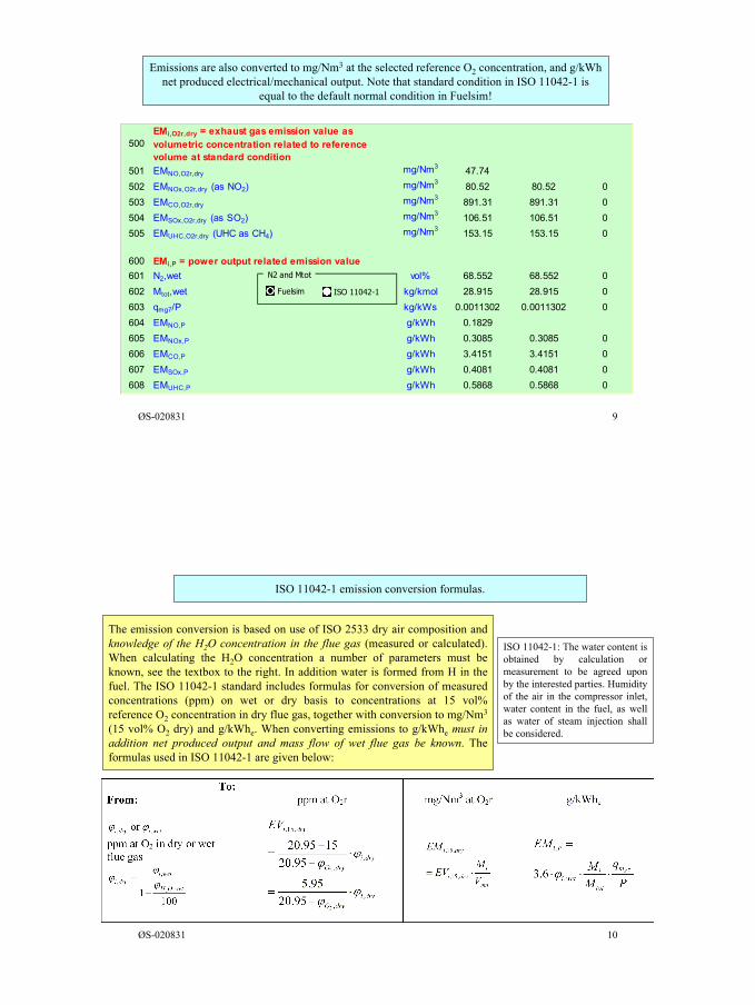
5
ØS-020831 9
Emissions are also converted to mg/Nm3 at the selected reference O2 concentration, and g/kWhnet produced electrical/mechanical output. Note that standard condition in ISO 11042-1 is
equal to the default normal condition in Fuelsim!
500EMi,O2r,dry = exhaust gas emission value as volumetric concentration related to reference volume at standard condition
501 EMNO,O2r,dry mg/Nm3 47.74502 EMNOx,O2r,dry (as NO2) mg/Nm3 80.52 80.52 0503 EMCO,O2r,dry mg/Nm3 891.31 891.31 0504 EMSOx,O2r,dry (as SO2) mg/Nm3 106.51 106.51 0505 EMUHC,O2r,dry (UHC as CH4) mg/Nm3 153.15 153.15 0
600 EMi,P = power output related emission value601 N2,wet vol% 68.552 68.552 0602 Mtot,wet kg/kmol 28.915 28.915 0603 qmg7/P kg/kWs 0.0011302 0.0011302 0604 EMNO,P g/kWh 0.1829605 EMNOx,P g/kWh 0.3085 0.3085 0606 EMCO,P g/kWh 3.4151 3.4151 0607 EMSOx,P g/kWh 0.4081 0.4081 0608 EMUHC,P g/kWh 0.5868 0.5868 0
N2 and Mtot
Fuelsim ISO 11042-1
ØS-020831 10
ISO 11042-1 emission conversion formulas.
ISO 11042-1: The water content isobtained by calculation ormeasurement to be agreed uponby the interested parties. Humidityof the air in the compressor inlet,water content in the fuel, as wellas water of steam injection shallbe considered.
The emission conversion is based on use of ISO 2533 dry air composition andknowledge of the H2O concentration in the flue gas (measured or calculated).When calculating the H2O concentration a number of parameters must beknown, see the textbox to the right. In addition water is formed from H in thefuel. The ISO 11042-1 standard includes formulas for conversion of measuredconcentrations (ppm) on wet or dry basis to concentrations at 15 vol%reference O2 concentration in dry flue gas, together with conversion to mg/Nm3
(15 vol% O2 dry) and g/kWhe. When converting emissions to g/kWhe must inaddition net produced output and mass flow of wet flue gas be known. Theformulas used in ISO 11042-1 are given below:
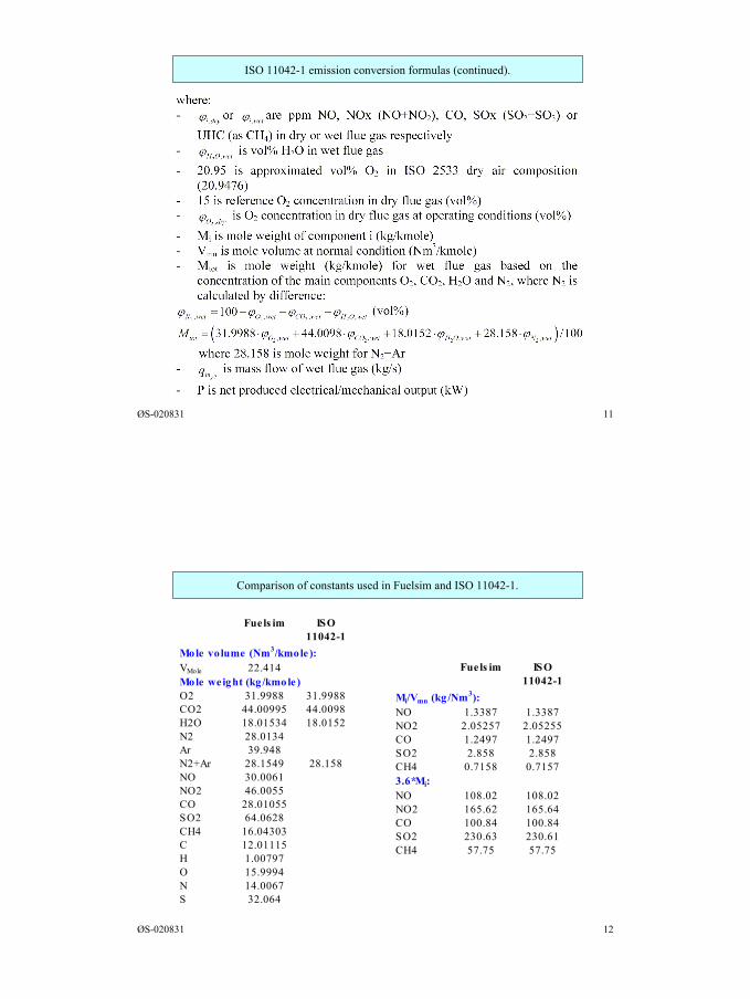
6
ØS-020831 11
ISO 11042-1 emission conversion formulas (continued).
ØS-020831 12
Comparison of constants used in Fuelsim and ISO 11042-1.
Fuels im ISO11042-1
Mole vo lume (Nm3/kmole):VMole 22.414Mole weight (kg /kmole)O2 31.9988 31.9988CO2 44.00995 44.0098H2O 18.01534 18.0152N2 28.0134Ar 39.948N2+Ar 28.1549 28.158NO 30.0061NO2 46.0055CO 28.01055SO2 64.0628CH4 16.04303C 12.01115H 1.00797O 15.9994N 14.0067S 32.064
Fuels im ISO11042-1
Mi/Vmn (kg /Nm3):NO 1.3387 1.3387NO2 2.05257 2.05255CO 1.2497 1.2497SO2 2.858 2.858CH4 0.7158 0.71573.6*Mi:NO 108.02 108.02NO2 165.62 165.64CO 100.84 100.84SO2 230.63 230.61CH4 57.75 57.75