Nordson MicroMax Boothemanuals.nordson.com/finishing/files/Stockport/768635_11.pdf · Nordson...
66
Nordson MicroMax Booth Manual Spray Booth Manual P/N 768635_11 - English - Issued 11/17 Keep for future reference NORDSON (UK) LTD. D STOCKPORT
-
Upload
truongnhan -
Category
Documents
-
view
219 -
download
0
Transcript of Nordson MicroMax Boothemanuals.nordson.com/finishing/files/Stockport/768635_11.pdf · Nordson...

Nordson MicroMax BoothManual Spray Booth
Manual P/N 768635_11- English -
Issued 11/17
Keep for future reference
NORDSON (UK) LTD. � STOCKPORT

��2017 Nordson CorporationAll rights reserved
MicroMaxIssued 11/17
COV_EN_768635_11
Order numberP/N = Order number for Nordson products
NoticeThis is a Nordson Corporation publication which is protected by copyright. Original copyright date 2000.
No part of this document may be photocopied, reproduced, or translated to another language without the prior writtenconsent of Nordson Corporation. The information contained in this publication is subject to change without notice.
- Original Document -
TrademarksAccuJet, AeroCharge, Apogee, AquaGuard, Asymtek, Automove, Autotech, Baitgun, Blue Box, Bowtie, Build‐A‐Part, CanWorks, Century, CF, CleanSleeve,CleanSpray, Color‐on‐Demand, ColorMax, Control Coat, Coolwave, Cross‐Cut, cScan+, Dage, Dispensejet, DispenseMate, DuraBlue, DuraDrum, Durafiber,DuraPail, Dura‐Screen, Durasystem, Easy Coat, Easymove Plus, Ecodry, Econo‐Coat, e.DOT, EFD, Emerald, Encore, ESP, e stylized, ETI‐stylized, Excel 2000,Fibrijet, Fillmaster, FlexiCoat, Flexi‐Spray, Flex‐O‐Coat, Flow Sentry, Fluidmove, FoamMelt, FoamMix, Fulfill, GreenUV, HDLV, Heli‐flow, Helix, Horizon, Hot Shot,iControl, iDry, iFlow, Isocoil, Isocore, Iso‐Flo, iTRAX, JR, KB30, Kinetix, KISS, Lean Cell, Little Squirt, LogiComm, Magnastatic, March, Maverick, MEG, Meltex,Microcoat, Micromark, Micromedics, Micro‐Meter, MicroSet, Microshot, Millenium, Mini Blue, Mini Squirt, Moist‐Cure, Mountaingate, MultiScan, NexJet, No‐Drip,Nordson, Optimum, Package of Values, Paragon, PatternView, PermaFlo, PICO, PicoDot, PluraFoam, Porous Coat, PowderGrid, Powderware, Precisecoat,PRIMARC, Printplus, Prism, ProBlue, Prodigy, Pro‐Flo, Program‐A‐Bead, Program‐A‐Shot, Program‐A‐Stream, Program‐A‐Swirl, ProLink, Pro‐Meter, Pro‐Stream,RBX, Rhino, Saturn, Saturn with rings, Scoreguard, SC5, S. design stylized, Seal Sentry, Sealant Equipment & Engineering, Inc., SEE and design, See‐Flow, SelectCharge, Select Coat, Select Cure, Servo‐Flo, Shot‐A‐Matic, Signature, Slautterback, Smart‐Coat, Smart‐Gun, Solder Plus, Spectrum, Speed‐Coat, Spraymelt, SpraySquirt, Super Squirt, SureBead, Sure Clean, Sure Coat, Sure‐Max, Sure Wrap, Tela‐Therm, Tip‐Seal, Tracking Plus, TRAK, Trends, Tribomatic, TrueBlue, TrueCoat,Tubesetter, Ultra, UniScan, UpTime, u‐TAH, Value Plastics, Vantage, Veritec, VersaBlue, Versa‐Coat, VersaDrum, VersaPail, Versa‐Screen, Versa‐Spray, VP QuickFit, Walcom, Watermark, When you expect more., X‐Plane are registered trademarks - ® - of Nordson Corporation.
Accubar, Active Nozzle, Advanced Plasma Systems, AeroDeck, AeroWash, Allegro, AltaBlue, AltaSlot, Alta Spray, AquaCure, Artiste, ATS, Auto‐Flo, AutoScan,Axiom, Best Choice, BetterBook, Blue Series, Bravura, CanNeck, CanPro, Celero, Chameleon, Champion, Check Mate, ClassicBlue, Classic IX, Clean Coat, Cobalt,ContourCoat, Controlled Fiberization, Control Weave, CPX, cSelect, Cyclo‐Kinetic, DispensLink, DropCure, Dry Cure, DuraBraid, DuraCoat, e.dot+, E‐Nordson,Easy Clean, EasyOn, EasyPW, Eclipse, Equalizer, EquiBead, Exchange Plus, FillEasy, Fill Sentry, Flow Coat, Fluxplus, Freedom, G‐Net, G‐Site, Genius, Get GreenWith Blue, Gluie, Ink‐Dot, IntelliJet, iON, Iso‐Flex, iTrend, KVLP, Lacquer Cure, Maxima, Mesa, MicroFin, MicroMax, Mikros, MiniEdge, Minimeter, MonoCure, Multifil,MultiScan, Myritex, Nano, OmniScan, OptiMix, OptiStroke, Optix, Origin, Partnership+Plus, PatternJet, PatternPro, PCI, PharmaLok, Pinnacle, Plasmod, PluraMix,Powder Pilot, Powder Port, Powercure, Process Sentry, Pulse Spray, PURBlue, PURJet, PurTech, Quad Cure, Quantum, Ready Coat, RediCoat, RollVIA, Royal Blue,Select Series, Sensomatic, Shaftshield, SheetAire, Smart, Smartfil, SolidBlue, Spectral, Spectronic, SpeedKing, Spray Works, StediFlo, StediTherm, Summit, SureBrand, SureFoam, SureMix, SureSeal, Swirl Coat, TAH, Tempus, ThruWave, TinyCure, Trade Plus, Trilogy, Ultra FoamMix, UltraMax, Ultrasaver, Ultrasmart,Universal, ValueMate, Versa, Viper, Vista, WebCure, YESTECH, 2 Rings (Design) are trademarks - � - of Nordson Corporation.
Designations and trademarks stated in this document may be brands that, when used by third parties for their own purposes, could lead to violation of the owners' rights.
� http://www.nordson.com/en/global-directory


Table of Contents I
��2017 Nordson CorporationAll rights reserved
MicroMaxIssued 11/17
P/N 768635_11
Table of Contents
Your Safety is Important to Nordson O‐1. . . . . . . . . . . . . . . . . . . . . . . . . . . . .
Manufacturer of Equipment O‐1. . . . . . . . . . . . . . . . . . . . . . . . . . . . . . . . . . . . .
1. Introduction 1‐1. . . . . . . . . . . . . . . . . . . . . . . . . . . . . . . . . . . . . . . . . . . . . . .
2. Qualified Personnel 1‐1. . . . . . . . . . . . . . . . . . . . . . . . . . . . . . . . . . . . . . . .
3. Intended Use 1‐1. . . . . . . . . . . . . . . . . . . . . . . . . . . . . . . . . . . . . . . . . . . . .
4. Regulations and Approvals 1‐1. . . . . . . . . . . . . . . . . . . . . . . . . . . . . . . . .
5. Personal Safety 1‐2. . . . . . . . . . . . . . . . . . . . . . . . . . . . . . . . . . . . . . . . . . .
6. Fire Safety 1‐3. . . . . . . . . . . . . . . . . . . . . . . . . . . . . . . . . . . . . . . . . . . . . . .
7. Action in the Event of a Malfunction 1‐4. . . . . . . . . . . . . . . . . . . . . . . . . .
8. Disposal 1‐4. . . . . . . . . . . . . . . . . . . . . . . . . . . . . . . . . . . . . . . . . . . . . . . . .
1. Intended Use 2‐1. . . . . . . . . . . . . . . . . . . . . . . . . . . . . . . . . . . . . . . . . . . . .
2. Features 2‐2. . . . . . . . . . . . . . . . . . . . . . . . . . . . . . . . . . . . . . . . . . . . . . . . .
1. Transport 3‐1. . . . . . . . . . . . . . . . . . . . . . . . . . . . . . . . . . . . . . . . . . . . . . . .
2. Unpacking 3‐1. . . . . . . . . . . . . . . . . . . . . . . . . . . . . . . . . . . . . . . . . . . . . . . .
3. Removing 3‐1. . . . . . . . . . . . . . . . . . . . . . . . . . . . . . . . . . . . . . . . . . . . . . . .
4. Storage 3‐1. . . . . . . . . . . . . . . . . . . . . . . . . . . . . . . . . . . . . . . . . . . . . . . . . .
5. Disposal 3‐1. . . . . . . . . . . . . . . . . . . . . . . . . . . . . . . . . . . . . . . . . . . . . . . . .
6. Setting up the Unit 3‐2. . . . . . . . . . . . . . . . . . . . . . . . . . . . . . . . . . . . . . . . .
7. Using New Cartridges 3‐2. . . . . . . . . . . . . . . . . . . . . . . . . . . . . . . . . . . . . .
8. Electrical 3‐3. . . . . . . . . . . . . . . . . . . . . . . . . . . . . . . . . . . . . . . . . . . . . . . . .
9. Pneumatic 3‐3. . . . . . . . . . . . . . . . . . . . . . . . . . . . . . . . . . . . . . . . . . . . . . . .
Congratulations on thePurchase of Your NordsonProduct
Section 1Safety
Section 2Description
Section 3Installation

Table of ContentsII
��2017 Nordson CorporationAll rights reserved
MicroMaxIssued 11/17
P/N 768635_11
1. Daily Start up and Shutdown 4‐1. . . . . . . . . . . . . . . . . . . . . . . . . . . . . . . .
1. Daily Maintenance 5‐1. . . . . . . . . . . . . . . . . . . . . . . . . . . . . . . . . . . . . . . . .
2. Routine Maintenance 5‐2. . . . . . . . . . . . . . . . . . . . . . . . . . . . . . . . . . . . . .
Fan Assembly 5‐2. . . . . . . . . . . . . . . . . . . . . . . . . . . . . . . . . . . . . . . . . .
Cartridges 5‐2. . . . . . . . . . . . . . . . . . . . . . . . . . . . . . . . . . . . . . . . . . . . .
Fluid Beds 5‐2. . . . . . . . . . . . . . . . . . . . . . . . . . . . . . . . . . . . . . . . . . . . .
Compressed Air 5‐2. . . . . . . . . . . . . . . . . . . . . . . . . . . . . . . . . . . . . . . .
3. Fluid Bed Replacement 5‐3. . . . . . . . . . . . . . . . . . . . . . . . . . . . . . . . . . . .
4. Blow Down Valve Assembly Replacement 5‐4. . . . . . . . . . . . . . . . . . . .
5. Cartridge Replacement 5‐4. . . . . . . . . . . . . . . . . . . . . . . . . . . . . . . . . . . . .
1. Important Hints for Troubleshooting 6‐1. . . . . . . . . . . . . . . . . . . . . . . . . .
1. Introduction 7‐1. . . . . . . . . . . . . . . . . . . . . . . . . . . . . . . . . . . . . . . . . . . . . . .
Using the Illustrated Parts List 7‐1. . . . . . . . . . . . . . . . . . . . . . . . . . . . .
MicroMax 1 Illustration 7‐2. . . . . . . . . . . . . . . . . . . . . . . . . . . . . . . . . . .
MicroMax 2 Illustration 7‐3. . . . . . . . . . . . . . . . . . . . . . . . . . . . . . . . . . .
MicroMax 3/3a & 17 Illustration 7‐4. . . . . . . . . . . . . . . . . . . . . . . . . . . .
MicroMax 4 Illustration 7‐5. . . . . . . . . . . . . . . . . . . . . . . . . . . . . . . . . . .
MicroMax 5 Illustration 7‐6. . . . . . . . . . . . . . . . . . . . . . . . . . . . . . . . . . .
2. Parts List MicroMax 1 - 5 & 17 7‐7. . . . . . . . . . . . . . . . . . . . . . . . . . . . . . .
MicroMax 7-16 Module Illustration 7‐8. . . . . . . . . . . . . . . . . . . . . . . . .
3. Parts List MicroMax 7 - 16 7‐9. . . . . . . . . . . . . . . . . . . . . . . . . . . . . . . . . .
4. MicroMax Sieve Hopper 7‐10. . . . . . . . . . . . . . . . . . . . . . . . . . . . . . . . . . .
Section 4Operation
Section 5Maintenance
Section 6Troubleshooting
Section 7Parts

Table of Contents III
��2017 Nordson CorporationAll rights reserved
MicroMaxIssued 11/17
P/N 768635_11
1. Electrical 8‐1. . . . . . . . . . . . . . . . . . . . . . . . . . . . . . . . . . . . . . . . . . . . . . . . .
2. Weights 8‐2. . . . . . . . . . . . . . . . . . . . . . . . . . . . . . . . . . . . . . . . . . . . . . . . . .
3. Noise 8‐2. . . . . . . . . . . . . . . . . . . . . . . . . . . . . . . . . . . . . . . . . . . . . . . . . . . .
4. Pneumatic Supply 8‐2. . . . . . . . . . . . . . . . . . . . . . . . . . . . . . . . . . . . . . . . .
5. MicroMax 1 Dimensions 8‐3. . . . . . . . . . . . . . . . . . . . . . . . . . . . . . . . . . . .
6. MicroMax 2 Dimensions 8‐3. . . . . . . . . . . . . . . . . . . . . . . . . . . . . . . . . . . .
7. MicroMax 3 Dimensions 8‐4. . . . . . . . . . . . . . . . . . . . . . . . . . . . . . . . . . . .
8. MicroMax 4 Dimensions 8‐4. . . . . . . . . . . . . . . . . . . . . . . . . . . . . . . . . . . .
9. MicroMax 5 Dimensions 8‐5. . . . . . . . . . . . . . . . . . . . . . . . . . . . . . . . . . . .
10. MicroMax 7-16 Module Dimensions 8‐5. . . . . . . . . . . . . . . . . . . . . . . . . .
11. MicroMax 7 Dimensions 8‐6. . . . . . . . . . . . . . . . . . . . . . . . . . . . . . . . . . . .
12. MicroMax 8 Dimensions 8‐6. . . . . . . . . . . . . . . . . . . . . . . . . . . . . . . . . . . .
13. MicroMax 9 Dimensions 8‐7. . . . . . . . . . . . . . . . . . . . . . . . . . . . . . . . . . . .
14. MicroMax 10 Dimensions 8‐7. . . . . . . . . . . . . . . . . . . . . . . . . . . . . . . . . . .
15. MicroMax 11 Dimensions 8‐8. . . . . . . . . . . . . . . . . . . . . . . . . . . . . . . . . . .
16. MicroMax 12 Dimensions 8‐8. . . . . . . . . . . . . . . . . . . . . . . . . . . . . . . . . . .
17. MicroMax 13 Dimensions 8‐9. . . . . . . . . . . . . . . . . . . . . . . . . . . . . . . . . . .
18. MicroMax 14 Dimensions 8‐9. . . . . . . . . . . . . . . . . . . . . . . . . . . . . . . . . . .
19. MicroMax 15 Dimensions 8‐10. . . . . . . . . . . . . . . . . . . . . . . . . . . . . . . . . .
20. MicroMax 16 Dimensions 8‐10. . . . . . . . . . . . . . . . . . . . . . . . . . . . . . . . . .
21. MicroMax 17 Dimensions 8-11. . . . . . . . . . . . . . . . . . . . . . . . . . . . . . . . . .
Section 8Specifications

Table of ContentsIV
��2017 Nordson CorporationAll rights reserved
MicroMaxIssued 11/17
P/N 768635_11

O‐1Introduction
��2013 Nordson CorporationAll rights reserved
MicroMaxIssued 12/13
STOCKCONG_EN_A-1299
Congratulations on the Purchase ofYour Nordson Product
Nordson equipment is engineered and manufactured in accordance withstrict specifications, using high quality components and state-of-the-arttechnologies that assure reliable, long-term performance. Your productwas thoroughly tested for proper operation prior to shipment.
Before unpacking and installing your new equipment, please read thismanual. It is your guide to safe installation, productive operation andeffective maintenance. We recommend that you keep the manualavailable for future reference.
Carefully read the Safety section. Your product is designed for safeoperation when used according to the published instructions. Potentialhazards exist when operating instructions are not followed.
Nordson (U.K.) Ltd.Ashurst DriveCheadle HeathStockportEnglandSK3 0RY
Telephone: 0044 (0) 161-495-4200Fax: 0044 (0) 161-428-6716
For a list of local Nordson organisations, see Nordson International.
Your Safety is Important toNordson
Manufacturer of Equipment

O‐2 Introduction
��2013 Nordson CorporationAll rights reserved
MicroMaxIssued 12/13
STOCKCONG_EN_A-1299

��2013 Nordson CorporationAll rights reserved
S1EN-03-[SF-Powder]-6
Section 1
Safety

Safety1‐0
��2013 Nordson CorporationAll rights reserved
Issued 10/98
S1EN-03-[SF-Powder]-6

Safety 1‐1
��2013 Nordson CorporationAll rights reserved
S1EN-03-[SF-Powder]-6
Section 1Safety
Read and follow these safety instructions. Task and equipment specificwarnings, cautions, and instructions are included in equipmentdocumentation where appropriate.
Make sure all equipment documentation, including these instructions, isaccessible to all persons operating or servicing equipment.
Equipment owners are responsible for making sure that Nordsonequipment is installed, operated, and serviced by qualified personnel.Qualified personnel are those employees or contractors who are trained tosafely perform their assigned tasks. They are familiar with all relevantsafety rules and regulations and are physically capable of performing theirassigned tasks.
Use of Nordson equipment in ways other than those described in thedocumentation supplied with the equipment may result in injury to personsor damage to property.
Some examples of unintended use of equipment include
� using incompatible materials
� making unauthorized modifications
� removing or bypassing safety guards or interlocks
� using incompatible or damaged parts
� using unapproved auxiliary equipment
� operating equipment in excess of maximum ratings
Make sure all equipment is rated and approved for the environment inwhich it is used. Any approvals obtained for Nordson equipment will bevoided if instructions for installation, operation, and service are notfollowed.
1. Introduction
2. Qualified Personnel
3. Intended Use
4. Regulations andApprovals

Safety1‐2
��2013 Nordson CorporationAll rights reserved
Issued 10/98
S1EN-03-[SF-Powder]-6
To prevent injury follow these instructions.
� Do not operate or service equipment unless you are qualified.
� Do not operate equipment unless safety guards, doors, or covers are
intact and automatic interlocks are operating properly. Do not bypassor disarm any safety devices.
� Keep clear of moving equipment. Before adjusting or servicing any
moving equipment, shut off the power supply and wait until theequipment comes to a complete stop. Lock out power and secure theequipment to prevent unexpected movement.
� Relieve (bleed off) hydraulic and pneumatic pressure before adjusting
or servicing pressurized systems or components. Disconnect, lockout, and tag switches before servicing electrical equipment.
� While operating manual electrostatic spray guns, make sure you are
grounded. Wear electrically conductive gloves or a grounding strapconnected to the gun handle or other true earth ground. Do not wearor carry metallic objects such as jewelry or tools.
� If you receive even a slight electrical shock, shut down all electrical or
electrostatic equipment immediately. Do not restart the equipmentuntil the problem has been identified and corrected.
� Obtain and read Material Safety Data Sheets (MSDS) for all materials
used. Follow the manufacturer's instructions for safe handling and useof materials, and use recommended personal protection devices.
� To prevent injury, be aware of less‐obvious dangers in the workplace
that often cannot be completely eliminated, such as hot surfaces,sharp edges, energized electrical circuits, and moving parts thatcannot be enclosed or otherwise guarded for practical reasons.
5. Personal Safety

Safety 1‐3
��2013 Nordson CorporationAll rights reserved
S1EN-03-[SF-Powder]-6
To avoid a fire or explosion, follow these instructions.
� Ground all conductive equipment in the spray area. Check equipment
and workpiece grounding devices regularly. Resistance to groundmust not exceed one mega-ohm.
� Shut down all equipment immediately if you notice static sparking or
arcing. Do not restart the equipment until the cause has beenidentified and corrected.
� Do not smoke, weld, grind, or use open flames where flammable
materials are being used or stored.
� Provide adequate ventilation to prevent dangerous concentrations of
volatile materials or vapors. Refer to local codes or your materialMSDS for guidance.
� Do not disconnect live electrical circuits while working with flammable
materials. Shut off power at a disconnect switch first to preventsparking.
� Know where emergency stop buttons, shutoff valves, and fire
extinguishers are located. If a fire starts in a spray booth, immediatelyshut off the spray system and exhaust fans.
� Shut off electrostatic power and ground the charging system before
adjusting, cleaning, or repairing electrostatic equipment.
� Clean, maintain, test, and repair equipment according to the
instructions in your equipment documentation.
� Use only replacement parts that are designed for use with original
equipment. Contact your Nordson representative for parts informationand advice.
6. Fire Safety

Safety1‐4
��2013 Nordson CorporationAll rights reserved
Issued 10/98
S1EN-03-[SF-Powder]-6
If a system or any equipment in a system malfunctions, shut off the systemimmediately and perform the following steps:
� Disconnect and lock out electrical power. Close pneumatic shutoff
valves and relieve pressures.
� Identify the reason for the malfunction and correct it before restarting
the equipment.
Dispose of equipment and materials used in operation and servicingaccording to local codes.
7. Action in the Event of aMalfunction
8. Disposal

��2013 Nordson CorporationAll rights reserved
MicroMaxIssued 12/13
P/N 768635_11
Section 2
Description

Description2‐0
��2013 Nordson CorporationAll rights reserved
MicroMaxIssued 12/13
P/N 768635_11

Description 2‐1
��2013 Nordson CorporationAll rights reserved
MicroMaxIssued 12/13
P/N 768635_11
Section 2Description
Free standing ductless booth with built‐in cartridge recovery system formanual powder coating, useable as either multi colour, non‐recovery, ordedicated one colour use, with integral sieve and recycle.
1. Intended Use

Description2‐2
��2013 Nordson CorporationAll rights reserved
MicroMaxIssued 12/13
P/N 768635_11
Nordson cartridge filter powder recovery systems do not requireexpensive ductwork or explosion venting. All the air used to contain andrecover powder over‐spray passes through the cartridge filters beforebeing returned to the workshop as clean air. An operator controlled semiautomatic cleaning system prolongs cartridge life.
� Stainless steel canopy, constructed for durability and ease of
cleandown.
� Complete with electrical control panel.
� Integral sieve powder feed hopper within the base of the booth for
single colour use. (only on MicroMax 1-5)
� Fluorescent light in the booth canopy roof
(not available on MicroMax 5).
� Manual gun electrical service connection included.
� Simple installation. Single power and air connections only required.
� Quiet operation.
WARNING: MicroMax Booths are manufacture not to be ventedthrough a duct. If this is necessary, a fan assisted ductworksystem must be used, which gives negative pressure drop.
WARNING: MicroMax Booths are manufactured for light usewith one manual gun for single sige booths and two manual gunsfor double sided booths. MicroMax booths are not intended foruse with Automatic guns, if provision is made to comply with EN50177
2. Features

��2013 Nordson CorporationAll rights reserved
MicroMaxIssued 12/13
P/N 768635_11
Section 3
Installation

Installation3‐0
��2013 Nordson CorporationAll rights reserved
MicroMaxIssued 12/13
P/N 768635_11

Installation 3‐1
��2013 Nordson CorporationAll rights reserved
MicroMaxIssued 12/13
P/N 768635_11
Section 3Installation
WARNING: Allow only qualified personnel to perform thefollowing tasks. Observe and follow the safety instructions in thisdocument and all other related documentation.
Transport the unit so as to avoid damage. Do not throw the unit. Usesuitable packaging materials and sturdy cartons. See Specificationssection for dimensions and weights.
Protect the unit from exposure to humidity, dust and vibrations.
Carefully unpack the unit to avoid damaging it. Check for damage causedduring transport.
Save packing materials for possible later use. Otherwise recycle ordispose of properly according to local regulations.
Switch off the mains supply, then disconnect all electrical connectionsfrom the unit.
Pack the unit in suitable packing materials and sturdy cartons. Protectfrom humidity, dust and large temperature fluctuations (condensation).
Dispose of properly according to local regulations.
1. Transport
2. Unpacking
3. Removing
4. Storage
5. Disposal

Installation3‐2
��2013 Nordson CorporationAll rights reserved
MicroMaxIssued 12/13
P/N 768635_11
WARNING: Allow only qualified personnel to perform theinstallation. Observe safety instructions.
1. Check all electrical and pneumatic connections.
2. Check that the overload setting for the motor is set to a valueappropriate for the motor in use.
3. Start the fan and check operation of the fan contacter. Check the fanfor correct direction of rotation.
4. Set timer on airflow switch circuit to 5-8 seconds.
5. Check operation of the airflow switch. This is used to interlock theapplication equipment supply and should only be on when the fan isrunning.
6. Set all regulators to zero, ensure that the service air line has beendrained before opening the valve to the control panel. Check for airleaks, remedy as necessary.
7. Set the pulse air pressure to 4.5 bar.
8. Check operation of the booth light.
WARNING: The following steps describe procedures forseasoning of new cartridge filters. These steps must be followedwhenever 'new' cartridges are installed. Failure to properlyseason cartridges can result in early clogging filter media andloss of use.
6. Setting up the Unit
7. Using New Cartridges

Installation 3‐3
��2013 Nordson CorporationAll rights reserved
MicroMaxIssued 12/13
P/N 768635_11
WARNING: Allow only qualified personnel to perform electricalconnections. Observe the safety instructions.
A single supply cable is required to the control panel. The supply shouldbe fed from a suitable disconnect device. Introduce the cable into thepanel using an IP6X cable gland.
Ensure that all the electrical wires are suitably sized for the fan motorloading and adequate fuse/circuit protection is provided at the source ofsupply.
NOTE: The fan motor is designed to be switched ”direct‐on‐line” (refer tothe electrical circuit schematic supplied with the unit, for powerrequirements before installation).
On starting the fan motor, check for correct rotation, normally clockwiselooking at the motor from the impeller end, (air is pushed out of theexhaust on the fan scroll). Do this by starting and immediately stoppingthe fan motor. Proper fan rotation is extremely important. With the fanrunning in the wrong direction, it will deliver approximately 40% of its ratedair volume. Correct by reversing any two leads on the load side of the fanmotor starter.
Check operation of solenoid valves. The valves should open and closesequentially to the preset dwell between each pulse.
Before connecting to an air supply ensure that the available air is of thecorrect quality. (Refer to Technical Section). Nordson can advise onsuitable air conditioning equipment to provide air of a suitable quality.
The pneumatic connection (BSP thread) is made next to the air reservoiror into the Nordson control panel and is provided with a ball valve forsystem isolation. Ensure that when bringing in the air connection there isa drain leg for the collection of any materials or oil that may be in the airlines before the connection is made to the control panel.
Air pressure of approximately 4.5 bar is required for fast efficientoperation. We suggest a regulated supply be used (with a pressure gaugenext to reservoir or in the control panel) to ensure that these conditions arefulfilled. Failure to do so could result in poor cleaning of the cartridgemedia.
8. Electrical
9. Pneumatic

Installation3‐4
��2013 Nordson CorporationAll rights reserved
MicroMaxIssued 12/13
P/N 768635_11

��2013 Nordson CorporationAll rights reserved
MicroMaxIssued 12/13
P/N 768635_11
Section 4
Operation

Operation4‐0
��2013 Nordson CorporationAll rights reserved
MicroMaxIssued 12/13
P/N 768635_11

Operation 4‐1
��2013 Nordson CorporationAll rights reserved
MicroMaxIssued 12/13
P/N 768635_11
Section 4Operation
WARNING: Allow only qualified personnel to perform thefollowing tasks. Observe and follow the safety instructions in thisdocument and all other related documentation.
1. Turn on the supply to the control panel.
2. Turn on the panel isolator.
3. Start the fan.
4. If a powder re‐cycle system is fitted, turn on the controls and ensurecorrect operation especially that the fluidising air to the hopper hasbeen turned on and adjusted to allow the powder to bubble gently.
5. Turn on the lights.
6. Operate the powder spray equipment in accordance with themanufacturers instructions.
WARNING: Always ensure when cleaning the booth orapplication equipment that the fan is running and appropriatePersonal Protective Equipment is worn.
7. Shutdown the booth by reversing the above sequence.
8. To empty the booth hopper to a waste bucket, connect the output ofthe transfer pump located at the base of the hopper to the wastebucket. Connect the vent from the hopper back into the booth usingthe spigot supplied. Operate the empty switch until the bucket is full.Dispose of the waste material according to local regulations.
WARNING: The MicroMax internal sieve should not have morethan 10Kgs of powder laid on top. The Maximum pressure of thevibrator should not exceed 3 Bar, Otherwise the life of thevibrator can be dramatically reduced
1. Daily Startup andShutdown

Operation4‐2
��2013 Nordson CorporationAll rights reserved
MicroMaxIssued 12/13
P/N 768635_11

��2013 Nordson CorporationAll rights reserved
MicroMaxIssued 12/13
P/N 768635_11
Section 5
Maintenance

Maintenance5‐0
��2013 Nordson CorporationAll rights reserved
MicroMaxIssued 12/13
P/N 768635_11

Maintenance 5‐1
��2013 Nordson CorporationAll rights reserved
MicroMaxIssued 12/13
P/N 768635_11
Section 5Maintenance
WARNING: Allow only qualified personnel to perform thefollowing tasks. Observe and follow the safety instructions in thisdocument and all other related documentation.
WARNING: Breathing in certain airborne dusts (includingfinishing powders) may be hazardous to health. Ask the powdermanufacturer for a Material Safety Data Sheet (MSDS) forinformation. Use appropriate respiratory protection.
� Visually check the complete system for leaks, rectify.
� Check the operation of any powder transfer systems.
� At Least every hour press the filter cleaning pulse button located on
the main control panel.
� Every four (4) hours, with the fan operating, clean the booth interior
with a rubber squeegee, or other non‐sparking cleaning device, pullingthe powder into the hopper section of the booth.
� Every four (4) hours or less check the feeder hopper for powder level.
Before adding powder use the vacuum cleaner to prevent powder dustfrom getting out into the room.
� Every four (4) hours check the powder pump and gun, clean according
to the product manual.
� Every four (4) hours clean U.V. detector lenses if fitted.
� Every four (4) hours run the cartridge cleaning sequencer for at least
ten (10) minutes, longer if necessary, to maintain air flow.
1. Daily Maintenance

Maintenance5‐2
��2013 Nordson CorporationAll rights reserved
MicroMaxIssued 12/13
P/N 768635_11
� Check the hopper for foreign materials, empty and clean if necessary.
� Changes in vibration and noise levels are easily identified as an
indication to possible problems.
� Record the air flow at regular intervals; thus charted any degradation
of system performance due to cartridge blocking will becomeimmediately apparent.
� Signs of powder leakage may be due to the cartridge seal leaking.
Tighten up the cartridge after ensuring seal integrity
� Cartridges and final filters cannot be manually cleaned but must be
replaced.
� On units with final filters, powder leakage may not be noticed, but if
adequate records have been kept, the faults will be apparent.
� These will be damaged if they are stood on or allowed to become
damp. They must be replaced; SMOOTH SIDE UP.
� Open the drop leg. Using a clean white cloth check for water, oil or
other contaminants. Correct as necessary.
2. Routine Maintenance
Fan Assembly
Cartridges
Fluid Beds (where applicable)
Compressed Air
Maintenance 5‐3
��2013 Nordson CorporationAll rights reserved
MicroMaxIssued 12/13
P/N 768635_11
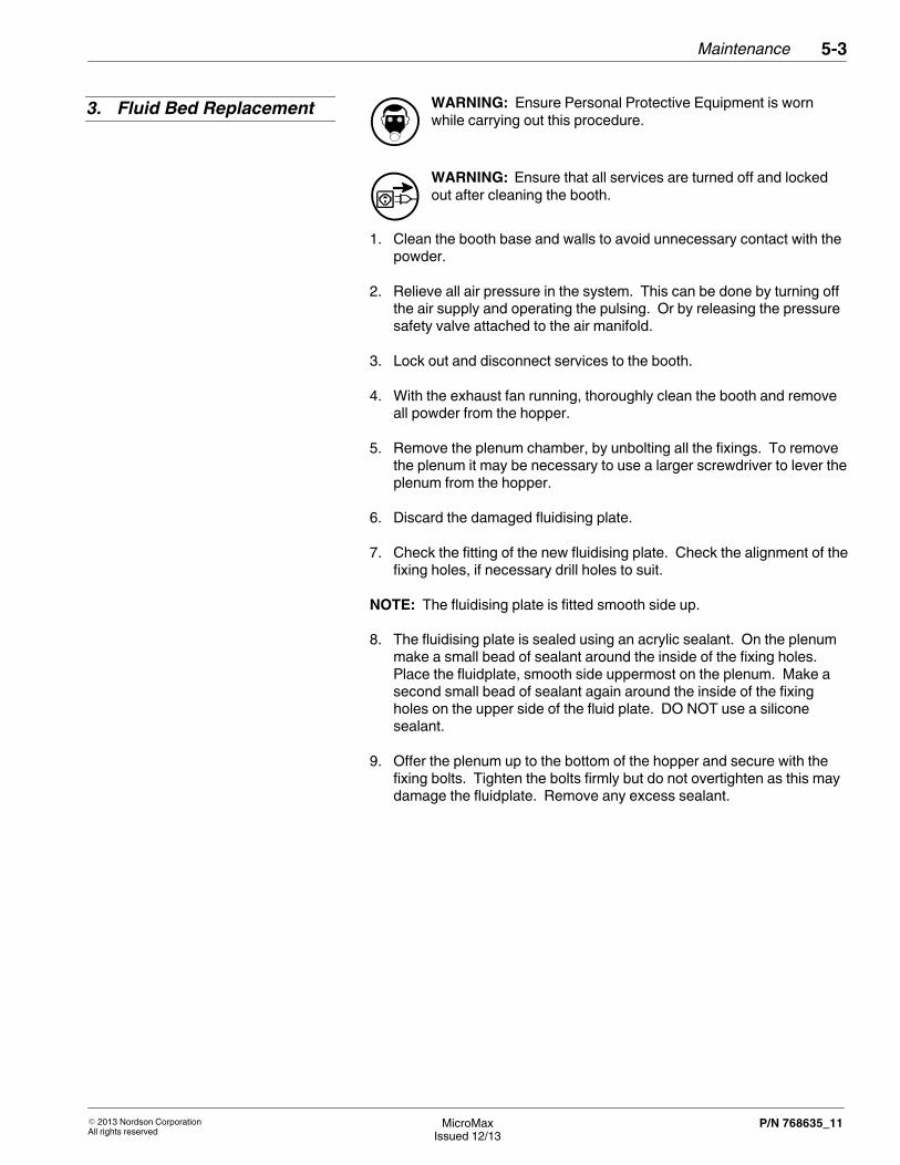
WARNING: Ensure Personal Protective Equipment is wornwhile carrying out this procedure.
WARNING: Ensure that all services are turned off and lockedout after cleaning the booth.
1. Clean the booth base and walls to avoid unnecessary contact with thepowder.
2. Relieve all air pressure in the system. This can be done by turning offthe air supply and operating the pulsing. Or by releasing the pressuresafety valve attached to the air manifold.
3. Lock out and disconnect services to the booth.
4. With the exhaust fan running, thoroughly clean the booth and removeall powder from the hopper.
5. Remove the plenum chamber, by unbolting all the fixings. To removethe plenum it may be necessary to use a larger screwdriver to lever theplenum from the hopper.
6. Discard the damaged fluidising plate.
7. Check the fitting of the new fluidising plate. Check the alignment of thefixing holes, if necessary drill holes to suit.
NOTE: The fluidising plate is fitted smooth side up.
8. The fluidising plate is sealed using an acrylic sealant. On the plenummake a small bead of sealant around the inside of the fixing holes.Place the fluidplate, smooth side uppermost on the plenum. Make asecond small bead of sealant again around the inside of the fixingholes on the upper side of the fluid plate. DO NOT use a siliconesealant.
9. Offer the plenum up to the bottom of the hopper and secure with thefixing bolts. Tighten the bolts firmly but do not overtighten as this maydamage the fluidplate. Remove any excess sealant.
3. Fluid Bed Replacement

Maintenance5‐4
��2013 Nordson CorporationAll rights reserved
MicroMaxIssued 12/13
P/N 768635_11
CAUTION: Before removing blow down valves ensure that theair supply and electrical supply have been turned off and lockedout.
1. Turn off the air supply.
2. Operate the cartridge pulsing for one minute or until the air manifold iscompletely empty.
3. Check on the pulsing air that all the air has been exhausted from theblow down plenum.
4. Turn off the electrical supply.
5. Remove the access panel at the rear of the booth.
6. Remove the suspect valve and inspect and replace if necessary.
7. Turn on supplies and test.
8. Replace the access panel at the rear of the booth.
WARNING: Ensure Personal Protective Equipment is wornwhile carrying out this procedure.
1. Turn off the booth and isolate.
2. Ensure all protective clothing is worn, firmly grasp the top of thecartridge and twist clockwise.
WARNING: A powder laden cartridge filter can be heavy. Itmay be necessary for two persons to be available to remove thecartridge filter.
3. Remove by twisting the body anti-clockwise to release and dispose ofthe old cartridges in accordance to local regualations.
4. Replace the cartridge in the reverse order.
4. Blow Down ValveAssembly Replacement
5. Cartridge Replacement

��2013 Nordson CorporationAll rights reserved
MicroMaxIssued 12/13
P/N 768635_11
Section 6
Troubleshooting

Troubleshooting6‐0
��2013 Nordson CorporationAll rights reserved
MicroMaxIssued 12/13
P/N 768635_11

Troubleshooting 6‐1
��2013 Nordson CorporationAll rights reserved
MicroMaxIssued 12/13
P/N 768635_11
Section 6Troubleshooting
WARNING: Allow only qualified personnel to perform thefollowing tasks. Observe and follow the safety instructions in thisdocument and all other related documentation.
The following tables provide general information for the troubleshooting ofbasic problems. Sometimes more detailed information, circuit diagrams ormeasuring devices are also needed for troubleshooting.
It must be noted that a fault can occur for several reasons. It is advisableto check all possible causes for a given fault. Obvious causes ofmalfunction such as broken wires, missing fasteners etc, should be notedduring visual inspections and corrected immediately.
The unit does not contain any user serviceable parts, any parts that failmust be replaced by approved parts available from Nordson.
Problem Possible Cause Corrective Action
Fan will not start Power off Switch on power
Overload operated Re‐set overload
Breaker tripped Investigate cause. Re‐set breaker
Wiring fault Repair or replace
Motor failure Investigate cause. Replace.
Timer on airflow switch setincorrectly.
Adjust timer to 5-8 seconds
Airflow switch set incorrectly Locate the airflow switch in fanhousing, and adjust setting, to beless sensitive.
Contactor fault Repair or replace. Check pushbutton wiring.
1. Important Hints forTroubleshooting

Troubleshooting6‐2
��2013 Nordson CorporationAll rights reserved
MicroMaxIssued 12/13
P/N 768635_11
Problem Possible Cause Corrective Action
Loss of extract throughput Cartridges not clean Manually run cleaning sequence forthirty (30) minutes
Low pulse pressure Set pressure at 4.5 bar
Cleaning valve fault Repair or replace
Powder escaping Cartridge leak Check cartridge seal
Tighten cartridge
Replace cartridge
Powder pump not correctly fitted tospigot
Refit, check condition of o‐ring.Replace o‐ring if necessary.
Powder hose leak Replace damaged hose and clips

��2013 Nordson CorporationAll rights reserved
MicroMaxIssued 12/13
P/N 768635_11
Section 7
Parts

Parts7‐0
��2013 Nordson CorporationAll rights reserved
MicroMaxIssued 12/13
P/N 768635_11

Parts 7‐1
��2013 Nordson CorporationAll rights reserved
MicroMaxIssued 12/13
P/N 768635_11
Section 7Parts
To order parts, call the Nordson Customer Service Center or your localNordson representative. Use the parts list, and the accompanyingillustration, to describe and locate parts correctly.
Numbers in the Item column correspond to numbers that identify parts inillustrations following each parts list. The code NS (not shown) indicatesthat a listed part is not illustrated. A dash (—) is used when the partnumber applies to all parts in the illustration.
The number in the Part column is the Nordson Corporation part number. Aseries of dashes in this column (‐ ‐ ‐ ‐ ‐ ‐) means the part cannot beordered separately.
The Description column gives the part name, as well as its dimensionsand other characteristics when appropriate. Indentions show therelationships between assemblies, subassemblies, and parts.
Item Part Description Quantity Note
— 000 0000 Assembly 1
1 000 000 � Subassembly 2 A
2 000 000 � � Part 1
� If you order the assembly, items 1 and 2 will be included.
� If you order item 1, item 2 will be included.
� If you order item 2, you will receive item 2 only.
The number in the Quantity column is the quantity required per unit,assembly, or subassembly. The code AR (As Required) is used if the partnumber is a bulk item ordered in quantities or if the quantity per assemblydepends on the product version or model.
Letters in the Note column refer to notes at the end of each parts list.Notes contain important information about usage and ordering. Specialattention should be given to notes.
1. Introduction
Using the Illustrated PartsList

Parts7‐2
��2013 Nordson CorporationAll rights reserved
MicroMaxIssued 12/13
P/N 768635_11
Front View Side View
Rear ViewPlan View
1
2
3
4
5
6
8
7
2off
MicroMax 1 Illustration
Parts 7‐3
��2013 Nordson CorporationAll rights reserved
MicroMaxIssued 12/13
P/N 768635_11
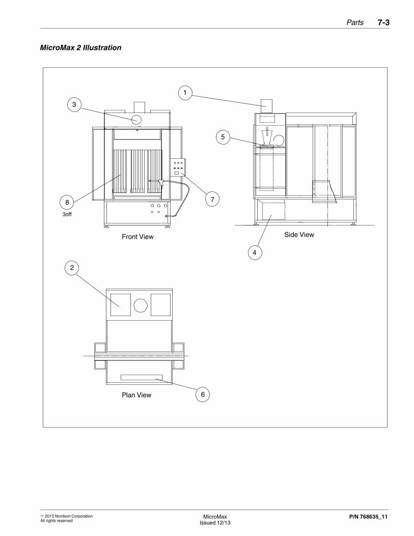
Plan View
Front View Side View
1
2
3
4
5
6
78
3off
MicroMax 2 Illustration

Parts7‐4
��2013 Nordson CorporationAll rights reserved
MicroMaxIssued 12/13
P/N 768635_11
Side View End View
Plan View
3 1
2
4
5
6
2off
2off
2off
7
8
6off
MicroMax 3/3A & 17 Illustration

Parts 7‐5
��2013 Nordson CorporationAll rights reserved
MicroMaxIssued 12/13
P/N 768635_11
Front View Side View
End View
MicroMax 4 Illustration

Parts7‐6
��2013 Nordson CorporationAll rights reserved
MicroMaxIssued 12/13
P/N 768635_11
Front View Side View
Plan View
MicroMax 5 Illustration

Parts 7‐7
��2013 Nordson CorporationAll rights reserved
MicroMaxIssued 12/13
P/N 768635_11
Item Part Description Quantity
- 768 750 MicroMax-1 Booth Assembly 1
- 768 776 MicroMax-X -1 Booth Assembly, c/w Auto Pulsing 1
- 768 751 MicroMax-2 Booth Assembly 1
- 768 777 MicroMax-X -2 Booth Assembly, c/w Auto Pulsing 1
- 768 752 MicroMax-3 Booth Assembly 1
- 768 778 MicroMax-X -3 Booth Assembly, c/w Auto Pulsing 1
- 768 774 MicroMax-3A Booth Assembly 1
- 768 779 MicroMax-X -3A Booth Assembly, c/w Auto Pulsing 1
- 768 753 MicroMax-4 Booth Assembly 1
- 768 780 MicroMax-X -4 Booth Assembly, c/w Auto Pulsing 1
- 768 758 MicroMax-5 Booth Assembly 1
- 768 781 MicroMax-X -5 Booth Assembly, c/w Auto Pulsing 1
- 768 775 MicroMax-17 Booth Assembly 1
- 768 793 MicroMax-X -17 Booth Assembly, c/w Auto Pulsing 1
1 � Fan Assembly 1
2 768 733 � PRE FILTER, 2M WIDE * REQUIRED LENGTH /M AR
3 768 769 � Air Pressure Switch AR
4 768 754 � Hopper with sieve, MicroMax AR
5 768 770 � Cartridge Mounting AR
6 � Light, fluorescent AR
7 � Control panel 1
8 768 755 � Filter, Cartridge, MicroMax NOTE A
NOTE A: MicroMax 1 contains 2 x Filter Cartridges,MicroMax 2,4 and 5 contains 3 x Filter CartridgesMicroMax 3 and 3A contains 6 x Filter CartridgesMicroMax 17 contains 8 x Filter Cartridges
B: MicroMax X Range is identical to the standard, except Individual Auto Pulsing is fitted as Standard
AR: As Required
Continued on next page
2. Parts List MicroMax 1 - 5and 17

Parts7‐8
��2013 Nordson CorporationAll rights reserved
MicroMaxIssued 12/13
P/N 768635_11
Plan View
Front View Side View
MicroMax 6 Module Illustration(Used on MicroMax 7-16)

Parts 7‐9
��2013 Nordson CorporationAll rights reserved
MicroMaxIssued 12/13
P/N 768635_11
Item Part Description Quantity
- 768 771 MicroMax-6 Module Assembly, c/w Control Panel 1
- 768 782 MicroMax-X-6 Booth Assembly, c/w Auto Pulsing & Control Panel 1
- 768 759 MicroMax-7 Booth Assembly 1
- 768 783 MicroMax-X-7 Booth Assembly, c/w Auto Pulsing 1
- 768 794 MicroMax-7A Booth Assembly 1
- 768 795 MicroMax-X-7A Booth Assembly, c/w Auto Pulsing 1
- 768 760 MicroMax-8 Booth Assembly 1
- 768 784 MicroMax-X-8 Booth Assembly, c/w Auto Pulsing 1
- 768 761 MicroMax-9 Booth Assembly 1
- 768 785 MicroMax-X-9 Booth Assembly, c/w Auto Pulsing 1
- 768 762 MicroMax-10 Booth Assembly 1
- 768 786 MicroMax-X-10 Booth Assembly, c/w Auto Pulsing 1
- 768 763 MicroMax-11 Booth Assembly 1
- 768 787 MicroMax-X-11 Booth Assembly, c/w Auto Pulsing 1
- 768 764 MicroMax-12 Booth Assembly 1
- 768 788 MicroMax-X-12 Booth Assembly, c/w Auto Pulsing 1
- 768 765 MicroMax-13 Booth Assembly 1
- 768 789 MicroMax-X-13 Booth Assembly, c/w Auto Pulsing 1
- 768 766 MicroMax-14 Booth Assembly 1
- 768 790 MicroMax-X-14 Booth Assembly, c/w Auto Pulsing 1
- 768 767 MicroMax-15 Booth Assembly 1
- 768 791 MicroMax-X-15 Booth Assembly, c/w Auto Pulsing 1
- 768 768 MicroMax-16 Booth Assembly 1
- 768 792 MicroMax-X-16 Booth Assembly, c/w Auto Pulsing 1
1 � Fan Assembly 1
2 768 757 � Filter, emergency MicroMax 2
3 768 769 � Air Pressure Switch 1
4 768 770 � Cartridge Mounting 1
5 768 755 � Filter, MicroMax NOTE A
NOTE A: MicroMax 6,7 and 7A contains 3 x Filter CartridgesMicroMax 8, 9 and 10 contains 6 x Filter CartridgesMicroMax 11, 12 and 13 contains 9 x Filter CartridgesMicroMax 14, 15 and 16 contains 12 x Filter Cartridges
B: MicroMax X Range is identical to the standard, except Individual Auto Pulsing is fitted as Standard
Continued on next page
3. Parts List MicroMax 7 - 16

Parts7‐10
��2013 Nordson CorporationAll rights reserved
MicroMaxIssued 12/13
P/N 768635_11
Only available for MicroMax 1 - 5 & 17
1
3
2
4 7
5
6
Item Part Description Quantity
- 768 754 Hopper with sieve, MicroMax NOTE A
1 768 732 � Sieve frame, MicroMax 1
2 768 729 � Fluid bed, MicroMax 1
3 163 556 � Mount, pump (Not Included) 1
4 768 731 � Seal, Sieve, MicroMax 3m
5 768 756 � Vibrator, MicroMax 1
NS 376 507 � Kit, Vibrator Repair, MicroMax 1
6 768 730 � Clamp, hopper, MicroMax 2
7 768 727 � Mount, sieve MicroMax 4
NOTE A: Sieve Hopper is only available for use on MicroMax 1 - 5 plus 17 only
4. MicroMax Sieve Hopper

��2013 Nordson CorporationAll rights reserved
MicroMaxIssued 12/13
P/N 768635_11
Section 8
Specifications

Specifications8‐0
��2013 Nordson CorporationAll rights reserved
MicroMaxIssued 12/13
P/N 768635_11

Specifications 8‐1
��2013 Nordson CorporationAll rights reserved
MicroMaxIssued 12/13
P/N 768635_11
Section 8Specifications
Micro 1 Micro 2 Micro3/3A
Micro 4 Micro 5
Power (kW) 1.5 2.2 2 x 2.2 2.2 2.2
M3/hr 3000 5600 11200 5600 5600
Micro 6 Micro7/7A
Micro 8 Micro 9 Micro 10
Power (kW) 2.2 2.2 2 x 2.2 2 x 2.2 2 x 2.2
M3/hr 5600 5600 11200 11200 11200
Micro 11 Micro 12 Micro 13 Micro 14 Micro 15
Power (kW) 3 x 2.2 3 x 2.2 3 x 2.2 4 x 2.2 4 x 2.2
M3/hr 16800 16800 16800 22400 22400
Micro 16 Micro 17
Power (kW) 4 x 2.2 2 x 7.5
M3/hr 22400 24480
NOTE: All booths work at 380/415 Volts at 50 Hz. Electrical SchematicDrawings should be located inside the control panel.
NOTE: All specification above are identical for the MicroMax-X range ofBooths
1. Electrical

Specifications8‐2
��2013 Nordson CorporationAll rights reserved
MicroMaxIssued 12/13
P/N 768635_11
Micro 1 Micro 2 Micro3/3A
Micro 4 Micro 5
Weight (kg)approx.shipping
450 700 1600 700 650
Micro 6 Micro7/7A
Micro 8 Micro 9 Micro 10
Weight (kg)approx.shipping
300 450 1400 1700 1700
Micro 11 Micro 12 Micro 13 Micro 14 Micro 15
Weight (kg)approx.shipping
2100 2100 2000 2500 2500
Micro 16 Micro 17
Weight (kg)approx.shipping
2500 2500
The weights above do not include the control panel.
NOTE: All weight specification above are identical for the MicroMax-Xrange of Booths
Measured at a distance of 1m from the surface of the unit and at a heightof 1.6 m <80 dBA.
The air supply for the powder spray booth shall be
� 2 °C dewpoint, oil free air
� Clean and dry filtered to 5�.
� 1/2” BSP at approx. 10 scfm per module
At a maximum supply pressure of 6.5 bar.
2. Weights
3. Noise
4. Pneumatic Supply

Specifications 8‐3
��2013 Nordson CorporationAll rights reserved
MicroMaxIssued 12/13
P/N 768635_11
Overall Height: 2700
1028
Overall Width: 1500Inc. Control Panel
1200
450
Overall Depth: 1530960
570
1250
600
1080
Overall Height: 2800
Overall Width: 2500
1300
-158
0
Overall Depth: 2320650
700
1260
840
5. MicroMax 1 & X-1Dimensions
6. MicroMax 2 & X-2Dimensions

Specifications8‐4
��2013 Nordson CorporationAll rights reserved
MicroMaxIssued 12/13
P/N 768635_11
1300
-158
0
Overall Height: 2730
Overall Length: 3540800
Overall Width: 2880
700
161012
60
1080
NOTE: MicroMax 3A has the same opening Dimensions, but the booth roof is 260mm Higher.
Overall Height: 2800
Overall Width: 2400 Overall Depth: 17301800
1350
7. MicroMax 3/3A & X-3/3ADimensions
8. MicroMax 4 & X-4Dimensions
Specifications 8‐5
��2013 Nordson CorporationAll rights reserved
MicroMaxIssued 12/13
P/N 768635_11
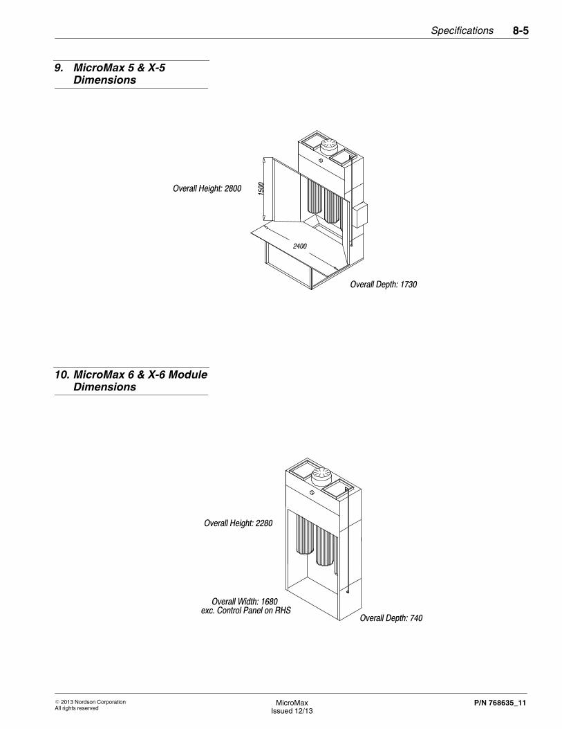
Overall Height: 2800
Overall Depth: 1730
2400
1500
Overall Height: 2280
Overall Width: 1680
Overall Depth: 740exc. Control Panel on RHS
9. MicroMax 5 & X-5Dimensions
10. MicroMax 6 & X-6 ModuleDimensions

Specifications8‐6
��2013 Nordson CorporationAll rights reserved
MicroMaxIssued 12/13
P/N 768635_11
Overall Depth: 2580
Overall Height: 2350
2050
1600 1800Overall Width: 1970inc. Control Panel on RHS
Overall Width: 2570inc. Control Panel on RHS
11. MicroMax 7 & X-7Dimensions
12. MicroMax 7A & X-7ADimensions

Specifications 8‐7
��2013 Nordson CorporationAll rights reserved
MicroMaxIssued 12/13
P/N 768635_11
Overall Width : 4760
Overall Height: 2270
3200
2050
Control Panel on RHS
1500
Overall Depth: 1690
Overall Width : 4360
2420
2800
1500
Overall Depth : 4200Control Panel on RHS
Overall Hieght : 2570
13. MicroMax 8 & X-8Dimensions
14. MicroMax 9 & X-9Dimensions

Specifications8‐8
��2013 Nordson CorporationAll rights reserved
MicroMaxIssued 12/13
P/N 768635_11
Overall Width : 39602400
2850
Control Panel on RHS
1500
Overall Depth : 3280
Overall Hieght : 3070
Overall Width : 5420
4800
2050
2700 Overall Depth : 3440Exc. Control Panel on RHS
Overall Hieght : 2350
15. MicroMax 10 & X-10Dimensions
16. MicroMax 11 & X-11Dimensions

Specifications 8‐9
��2013 Nordson CorporationAll rights reserved
MicroMaxIssued 12/13
P/N 768635_11
Overall Width : 50204200
2350
2700Exc. Control Panel on RHS
Overall Hieght : 2570
Overall Depth : 3440
Overall Width : 4280
2350
Overall Depth : 3440
Overall Hieght : 3070
2700Exc. Control Panel on RHS3460
17. MicroMax 12 & X-12Dimensions
18. MicroMax 13 & X-13Dimensions

Specifications8‐10
��2013 Nordson CorporationAll rights reserved
MicroMaxIssued 12/13
P/N 768635_11
Overall Width : 8060
Overall Hieght : 3070
Inc. Control Panel on RHS
Overall Depth : 40803340
6500
2200
1680
Overall Width : 7080Inc. Control Panel on RHS
Overall Hieght : 2570
Overall Depth : 4940
5520
2500
4200
1680
19. MicroMax 14 & X-14Dimensions
20. MicroMax 15 & X-15Dimensions

Specifications 8‐11
��2013 Nordson CorporationAll rights reserved
MicroMaxIssued 12/13
P/N 768635_11
Overall Width : 6080Inc. Control Panel on RHS
Overall Depth : 4940
Overall Hieght : 30702920
4520
4200
1680
Overall Hieght : 3400
Overall Width : 3600
Overall Length : 44801070
1910
1800
1100
21. MicroMax 16 & X-16Dimensions
22. MicroMax 17 & X-17Dimensions

Specifications8‐12
��2013 Nordson CorporationAll rights reserved
MicroMaxIssued 12/13
P/N 768635_11