Nordic APIs - Integrated Social Solutions for a Cloudy, Mobile World

NORDIC
MOBILE TELEPHONE
®
NMT DOC 450-3Nordic Mobile Telephone group
Technical Specification forthe Mobile Station
October 1995

NMT Doc 450-3, 1995-10-04
A full documentation of
NMT Doc 450-3Technical Specification for the Mobile Station
consists of:
A NMT Doc 450-3, 1995-10-04
B MS LETTERS TO MANUFACTURERS
- MS 88-26 15.07.1988 NMT Doc 88-2022 SIS specification- MS 88-27 29.09.1988 NMT Doc 88-2060 SIS specification- MS 88-29 30.11.1988 NMT Doc 88-2084 SIS specification- MS 89-31 29.05.1989 NMT Doc 89-2163 SIS specification- MS 89-32 06.10.1989 NMT Doc 89-2216 SIS specification
C 1995. The copyright to the specifications herein is property of TeleDanmark Mobil A/S, Denmark, Telecom Finland Ltd, Finland, TelenorMobil AS, Norway and Telia Mobitel AB, Sweden. The specifications maybe used and/or copied only with written permission.

NMT Doc 450-3, 1995-10-04 Contents 1(11)
CONTENTS
1. GENERAL
1.1 INTRODUCTION Rev 95-10-04 Ch 1.1 (3)
1.1.1 System concepts1.1.2 Radio frequencies1.1.2.1 Extended band (optional , subject to national regulations)1.1.3 Call set up procedures1.1.3.1 Call to mobile station1.1.3.2 Call from mobile station1.1.4 Switching call in progress
1.2 MOBILE STATION UNITS Rev 95-10-04 Ch. 1.2 (3)
1.2.1 Transceiver Unit1.2.2 Operational Controls Unit1.2.3 Logic and Control Unit1.2.4 Signalling equipment
1.3 GENERAL CONDITIONS Rev 95-10-04 Ch. 1.3 (10)
1.3.1 General requirements1.3.1.1 Marking of the equipment1.3.1.2 Warming up period1.3.2 Terminals1.3.2.1 Test terminals1.3.2.2 Antenna terminal1.3.2.3 Voice input and output terminals1.3.2.4 Arrangement for testing1.3.2.5 External equipment1.3.3 Test of the equipment1.3.3.1 Application of the test conditions1.3.3.2 Power supply1.3.4 Normal test conditions1.3.4.1 Normal temperature and humidity1.3.4.2 Normal test power source1.3.5 Extreme test conditions1.3.5.1 Temperatures at testing under extreme conditions1.3.5.2 Power supply voltages at testing under extreme conditions1.3.5.3 Procedure for tests at extreme temperatures1.3.5.4 Storage conditions1.3.6 Arrangement for test signals applied to the antenna terminal for receiver testing
purposes1.3.7 Artificial antenna (dummy load)

NMT Doc 450-3, 1995-10-04 Contents 2(11)
1.3.8 Test modulations1.3.8.1 Normal test modulation1.3.8.2 Data test modulation1.3.8.3 Supervisory signal modulation1.3.9 Definitions of some measuring instruments1.3.9.1 Adjacent channel power measuring receiver1.3.9.2 Psophometric filter1.3.9.3 SINAD meter1.3.10 Vibration test1.3.10.1 Vibration (Sweep)1.3.10.2 Vibration (Random), alternative test1.3.11 Test site and general arrangements for measurements involving the use of
radiated fields1.3.11.1 Test site1.3.11.2 Test antenna1.3.11.3 Substitution antenna1.3.11.4 Alternative indoor site1.3.12 Receiver rated audio output power
2. TRANSCEIVER UNIT
2.1 GENERAL Rev 95-10-04 Ch. 2.1 (1)
2.2 TRANSMITTER Rev 95-10-04 Ch. 2.2 (12)
2.2.1 Frequency range and channel separation2.2.1.1 Extension band (optional , subject to national regulations)2.2.2 Number of channels2.2.2.1 Extension band (optional, subject to national regulations)
2.2.3 Frequency error2.2.3.1 Definition2.2.3.2 Method of measurement2.2.3.3 Requirement2.2.4 Transmitter carrier power2.2.4.1 Definition2.2.4.2 Method of measurement2.2.4.3 Requirements2.2.4.4 Load test2.2.5 Transmitter carrier power control2.2.6 Carrier on/off condition and carrier rise/decay time2.2.7 Transmitter channel switching time2.2.8 Spurious emissions2.2.8.1 Definition2.2.8.2 Method of measuring the conducted power level2.2.8.3 Method of measuring the effective radiated power2.2.8.4 Requirements2.2.9 Frequency deviation2.2.9.1 Maximum permissible frequency deviation without supervisory signal2.2.9.1.1 Definition

NMT Doc 450-3, 1995-10-04 Contents 3(11)
2.2.9.1.2 Method of measurement2.2.9.1.3 Requirements2.2.10 Limiting characteristics of modulator2.2.10.1 Definition2.2.10.2 Method of measurement2.2.10.3 Requirements2.2.11 Adjacent channel power2.2.11.1 Definition2.2.11.2 Method of measurement2.2.11.3 Requirements2.2.12 Audio-frequency response of the transmitter2.2.12.1 Definition2.2.12.2 Method of measurement2.2.12.3 Requirements2.2.13 Harmonic distortion factor in transmission2.2.13.1 Definition2.2.13.2 Method of measurement2.2.13.3 Requirements2.2.14 Relative audio-frequency intermodulation product level of the transmitter2.2.14.1 Definition2.2.14.2 Method of measurement2.2.14.3 Requirements2.2.15 Residual modulation2.2.15.1 Definition2.2.15.2 Method of measurement2.2.15.3 Requirements2.2.16 Transmitter audio muting2.2.16.1 Definition2.2.16.2 Method of measurement2.2.16.3 Requirements
2.3 RECEIVER Rev 95-10-04 Ch. 2.3 (13)
2.3.1 Frequency range and channel separation2.3.1.1 Extension band (optional, subject to national regulations)
2.3.2 Number of channels2.3.2.1 Extension band (optional, subject to national regulations)2.3.2 Number of channels2.3.3 Duplex separation2.3.4 Receiver detection and switching time2.3.5 Reduced channel locking capability2.3.6 RF carrier detector2.3.7.1 RF sensitivity2.3.7.1.1 Definition2.3.7.1.2 Method of measurement2.3.7.1.3 Requirements2.3.7.2 Receiver duplex sensitivity degradation2.3.7.2.1 Definition

NMT Doc 450-3, 1995-10-04 Contents 4(11)
2.3.7.2.2 Method of measurement2.3.7.2.3 Requirements2.3.8 Co channel rejection2.3.8.1 Definition2.3.8.2 Method of measurement2.3.8.3 Requirements2.3.9 Adjacent channel selectivity2.3.9.1 Definition2.3.9.2 Method of measurement2.3.9.3 Requirements2.3.11 Spurious response rejection2.3.11.1 Definition2.3.11.2 Method of measurement2.3.11.3 Requirements2.3.12 Intermodulation rejection2.3.12.1 Definition2.3.12.2 Method of measurement2.3.12.3 Requirements2.3.13 Blocking2.3.13.1 Definition2.3.13.2 Method of measurement2.3.13.3 Requirements2.3.14 Spurious emissions2.3.14.1 Definition2.3.14.2 Method of measuring the conducted power2.3.14.3 Method of measuring the effective radiated power2.3.14.4 Requirements2.3.15 Harmonic distortion ratio2.3.15.1 Definition2.3.15.2 Method of measurement2.3.15.3 Requirements2.3.16 Relative audio frequency intermodulation product level2.3.16.1 Definition2.3.16.2 Method of measurement2.3.16.3 Requirements2.3.17 Amplitude characteristics of the receiver limiter2.3.17.1 Definition2.3.17.2 Method of measurement2.3.17.3 Requirements2.3.18 AM suppression2.3.18.1 Definition2.3.18.2 Method of measurement2.3.18.3 Requirements2.3.19 Noise and hum2.3.19.1 Definition2.3.19.2 Method of measurement2.3.19.3 Requirements2.3.20 Audio frequency response

NMT Doc 450-3, 1995-10-04 Contents 5(11)
2.3.20.1 Definition2.3.20.2 Method of measurement2.3.20.3 Requirements2.3.21 Receiver audio muting2.3.21.1 Definition2.3.21.2 Method of measurement2.3.21.3 Requirements
2.4 ∅ SIGNAL LOOP AND TRANSCEIVER COUPLINGRev 95-10-04 Ch. 2.4 (7)
2.4.1 Supervisory signal deviation2.4.1.1 Definition2.4.1.2 Method of measurement2.4.1.2.1 Calibration set up2.4.1.2.2 Measurement set up2.4.1.3 Requirements2.4.2 Transceiver coupling 2.4.2.1 RX-TX2.4.2.1.1 Definition2.4.2.1.2 Method of measurement2.4.2.1.3 Requirements2.4.2.2 TX-RX2.4.2.2.1 Definition2.4.2.2.2 Method of measurement2.4.2.2.3 Requirements2.4.3 Interference in the ∅ signal frequency band2.4.3.1 Definition2.4.3.2 Method of measurement2.4.3.3 Requirements2.4.4 Relative audio frequency intermodulation product level in the ∅-signal loop2.4.4.1 Definition2.4.4.2 Method of measurement2.4.4.3 Requirements
2.5 VOICE PROCESSING REQUIREMENTS, TRANSMITTINGRev 95-10-04 Ch. 2.5 (8)
2.5.1 Compression linearity2.5.1.1 Definition2.5.1.2 Method of measurement2.5.1.3 Requirements 2.5.2 Transient response of the compressor2.5.2.1 Definition2.5.2.2 Method of measurement2.5.2.3 Requirements2.5.3 Attack time and recovery time of the compressor

NMT Doc 450-3, 1995-10-04 Contents 6(11)
2.5.3.1 Definition2.5.3.2 Method of measurement2.5.3.3 Requirements2.5.4 Send frequency response2.5.4.1 Definition2.5.4.2 Method of measurement2.5.4.3 Requirements2.5.5 Send loudness rating2.5.5.1 Definition2.5.5.2 Calculation method2.5.5.3 Requirements2.5.6 Transmit distortion2.5.6.1 Definition2.5.6.2 Method of measurement2.5.6.3 Requirements2.5.7 Transmission idle noise2.5.7.1 Definition2.5.7.2 Method of measurement2.5.7.3 Requirements2.5.8 Noise cancelling device2.5.8.1 Definition2.5.8.2 Method of measurement2.5.8.3 Requirements2.5.9 Separate microphone
2.6 VOICE PROCESSING REQUIREMENTS, RECEIVINGRev 95-10-04 Ch. 2.6 (7)
2.6.1 Expansion linearity2.6.1.1 Definition2.6.1.2 Method of measurement2.6.1.3 Requirements2.6.2 Transient response of the expander2.6.2.1 Definition2.6.2.2. Method of measurement2.6.2.3 Requirements2.6.3 Receive frequency response2.6.3.1 Definition2.6.3.2 Method of measurement2.6.3.3 Requirements2.6.4 Receive loudness rating2.6.4.1 Definition2.6.4.2 Calculation method2.6.4.3 Requirements2.6.5 Receive volume control2.6.6 Receive harmonic distortion2.6.6.1 Definition2.6.6.2 Method of measurement

NMT Doc 450-3, 1995-10-04 Contents 7(11)
2.6.6.3 Requirements2.6.7 Receive idle noise2.6.7.1 Definition2.6.7.2 Method of measurement2.6.7.3 Requirements2.6.8 Maximum sound level of handset earpiece2.6.9 Volume control in "Hands-Free" mode
2.7 STABILITY LOSS Rev 95-10-04 Ch. 2.7 (1)
2.7.1 Definition2.7.2 Method of measurement2.7.3 Requirements
3. OPERATIONAL CONTROLS UNIT (OCU)Rev 95-10-04 Ch. 3 (11)
3.1 MOBILE TELEPHONE IDENTIFICATION NUMBER
3.1.1 Secret authentication key3.1.1.1 The generation and programming of SAKs3.1.1.1.1 General requirements3.1.1.1.2 Generation of the SAK3.2 "ON/OFF" SWITCH (OPTION)
3.3 HANDSET (OPTION)
3.4 "HANDS-FREE" OPERATION — "HANDS-FREE" BUTTON(OPTION)
3.5 DELETED
3.6 DIALLING FACILITIES (OPTION)
3.6.1 Push-button set3.6.2 Dialled digits memory (DDM)3.7 ACOUSTIC SIGNALS GENERATED BY THE MOBILE STATION (OPTION)
3.7.1 General3.7.2 Ringing signal3.7.3 Malfunction alarm3.8 COUNTRY SELECTOR (OPTION)
3.9 VISUAL INDICATORS
3.9.2 Service indicator3.9.3 Call received indicator (OPTION)3.9.4 Roaming alarm indicator3.9.5 Dialled digits display (OPTION)3.9.6 Electrical off hook indicator3.9.7 Selected country indicator (OPTION)3.10 SUPPLEMENTARY FACILITIES (OPTION)

NMT Doc 450-3, 1995-10-04 Contents 8(11)
3.10.1 SHIFT MODE
3.10.2 Immediate call transfer indication3.10.3 Transmission of MFT signalling from MS3.10.4 Locking facility
4. OPERATIONAL PROCEDURESRev 95-10-04 Ch. 4 (7)
4.1 GENERAL REQUIREMENTS
4.2 MANUAL ROAMING UPDATING
4.2.1 Updating by initiating "off-hook"4.2.2 Updating by generating a call4.3 ABBREVIATED DIALLING (OPTION)
4.4 DIALLED DIGITS MEMORY (DDM) (OPTION)
4.5 ADDITIONAL USE OF THE PUSH-BUTTON SET
5. LOGIC AND CONTROL UNIT (LCU) AND SIGNALLINGEQUIPMENT
5.1 GENERAL Rev 95-10-04 Ch. 5.1 (2)
5.2 DESCRIPTION OF LCU ACTIVITIESRev 95-10-04 Ch. 5.2 (18)5.2.1 Description of main states5.2.1.1 Power off5.2.1.2 Standby5.2.1.3 Conversation5.2.1.4 Search for channels5.2.1.4.1 Definitions5.2.1.4.2 Channel acceptance procedure5.2.1.5 Search for calling channel5.2.1.6 Search for free marked traffic channel (MS electrically off hook)5.2.1.7 Search for TC, roaming flag set, MS on hook5.2.1.8 Search for TC, no roaming flag set, MS on hook.5.2.1.9 Signalling schemes, (see fig 5.2. and paragraph 5.4)5.2.1.10 User initiated "on hook" in the signalling schemes5.2.1.11 User initiated "off hook" in the signalling schemes5.2.1.12 Authentication procedure and encryption of B-subscriber number5.2.2 Minor states within the signalling schemes5.2.3 Task description5.2.3.1 Power on task5.2.3.2 Power off task5.2.3.3 Selection of random channel5.2.3.4 Timing supervision.

NMT Doc 450-3, 1995-10-04 Contents 9(11)
5.3 INPUT/OUTPUT STATE RELATIONS Rev 95-10-04 Ch. 5.3 (20)
5.3.1 Structure of the state table
5.4 FLOW DIAGRAMS Rev 95-10-04 Ch. 5.4 (16)
5.4.1 Main states for LCU5.4.2 Call MS - MTX (signalling scheme A)5.4.3 Call MTX to MS (signalling scheme B)5.4.4 Call MTX-MS (signalling scheme B1)5.4.5 Switching call in progress (SCIP) (signalling scheme C) or MS power change.5.4.6 Updating roaming information (signalling scheme D)5.4.7 MS clearing5.4.8 Forced release from MTX5.4.9 Authentication during conversation
5.5 SIGNALLING EQUIPMENT FOR 1200 BAUD FFSK
Rev 95-10-04 Ch. 5.5 (2)
5.5.1 General description5.5.2 FFSK modulation in MS5.5.3 FFSK signal receiver5.5.4 Splitting in MS5.5.5 FFSK signalling detection time
5.6 TIMING IN THE MS Rev 95-10-04 Ch. 5.6 (3)
5.6.1 Time constants in the signalling procedure5.6.2 Timing between the signalling directions in MS5.6.3 Timing of call acknowledgement on calling channel and access on access channel5.6.4 Timing of transmission of frames 10b, 10c, 11a, 11b and 125.6.5 Timing of seizure on traffic channel5.6.6 Autonomous time-out
5.7 TRANSCEIVER INTERFACE Rev 95-10-04 Ch. 5.7 (1)
5.7.1 RF power control in MS5.7.1.1 MTX controlled maximum RF output power5.7.1.2 Autonomous power control in MS5.7.2 RF frequency control5.7.3 Audio muting5.7.4 RF carrier detector

NMT Doc 450-3, 1995-10-04 Contents 10(11)
6. SYSTEM TESTS Rev 95-10-04 Ch. 6 (9)
6.1 PERFORMANCE TESTS
6.1.1 Signalling sensitivity measured by call reception probability6.1.2 Co-channel data rejection6.1.3 Adjacent RF-signal decoding degradation6.1.4 RF intermodulation decoding degradation6.1.5 Signalling sensitivity in presence of RF signal fading measured by call reception
probability6.1.6 Data signal distortion6.1.7 Ability to interpret distorted data signals6.2 TIME CONSTANTS
6.2.1 Receiver switching time to next channel including FFSK detection time6.2.2 Transmitter start-up times6.2.2.1 Definition6.2.2.2 Requirements6.2.3 Call acknowledgement on CC6.2.4 Transmitter awake time6.2.5 Switching time to ordered channel6.2.5.1 Definition6.2.5.2 Method of measurements6.2.5.3 Requirements6.2.6 Transient behaviour of the transmitter6.2.6.1 Definition6.2.6.2 Method of measurements6.2.6.3 Requirements
6.3 ACCEPTANCE OF SIGNALS
6.4 FUNCTIONAL TEST
NMT Doc 450-3, 1995-10-04 Contents 11(11)
ANNEXES
Annex Contents Rev. No.of
pages
1 General information 95-10-04 4
2 Portable mobile station 95-10-04 5
3 Handheld mobile station (HMS) 95-10-04 6
4 Priority mobile station (PMS) 95-10-04 10
5 Payphone mobile station 95-10-04 6
6 Mobile station with MFT function 95-10-04 4
7 Mobile station with interface for external equipment 95-10-04 7
8 Mobile station with register recall function (OPTION) 95-10-04 3
9 Mobile station for combined use (HMS with booster) 95-10-04 1
10 Reserved
11 Mobile station equipped with more than one handset and/or operationalunit
95-10-04 2
12 Handheld mobile station with battery saving function 95-10-04 2
13 Reserved
14 Not in 450 system
15 Electrical interface used in the type test of the MS 95-10-04 1
16 Description of a random generator 95-10-04 3
17 Combined NMT-450/900 mobile station (CMS) 95-10-04 6
18 Requirements and test conditions for external equipment not specifiedelsewhere in MS specifications
95-10-04 6
19 Requirements concerning service mode and programming mode in NMTmobile stations
95-10-04 2
20 Requirements for NMT-mobile station equipped with a cordless handset 95-10-04 1
21 Data Mobile Station (DMS) 95-10-04 17
22 Mobile station integrated with a portable data terminal or personalcomputer. (CTMS)
95-10-04 6
23 Bar coding of subscription management related information 95-10-04 2

NMT Doc 450-3, 1995-10-04 Chapter 1.1 1(3)
1. GENERAL
1.1 INTRODUCTION
NMT-450, the Nordic Mobile Telephone System in the 450 MHz -band isdeveloped jointly by the Tele Danmark Mobil, Denmark, Telecom Finland,Finland, Tele-mobil, Norway and Telia Mobitel, Sweden in order to establisha compatible automatic public mobile telephone system in the Nordiccountries.
This document specifies the requirements for the mobile stations (MS) in thesystem. For detailed information about the system and the interfaces betweenthe system components, reference is made to NMT Doc 450-1, "SystemDescription", which is necessary for the use of this document.
The mobile stations of the system are fully compatible with the land based partof the system, regardless of which Nordic country the mobile station happensto be in at the moment. All mobile stations are given full roaming capability inall participating countries.
The mobile stations are to be purchased or leased by the subscribers. Theymust, however, be type approved by the type approval authority in thecountry of the subscriber. In specifying the requirements for type approval,one basic aim has been that to the subscribers, the system shall appear assimilar as possible to the fixed telephone network. This applies both to the useof the mobile station, the reliability of signalling, charging and to the servicesoffered.
1.1.1 System concepts
With reference to the detailed system description, NMT Doc 450-1, thefollowing lines are intended only as a very brief introduction to the system.
The interface between the system and the fixed telephone network is containedin the mobile telephone exchange (MTX). The base stations (BS) areconnected to the MTX which controls the traffic to and from the mobilestations. The switching functions are performed by the MTX.
The base stations are grouped into traffic areas. An MTX may control one ormore traffic areas.
At every base station, one channel is used as calling channel and is markedwith a special identification signal. One or several of the other channels, whenfree, are marked with a free traffic channel identification signal. Stand-bymobile stations in an area under a base station are locked to the callingchannel. "To minimise the possibility for illicit use of mobile stations, anauthentication procedure will take place on all mobile originated calls. TheMS shall also be able to answer an authentication procedure duringconversation. This will be used to authenticate the MS as a B-subscriber whencharging of B-subscriber is used."

NMT Doc 450-3, 1995-10-04 Chapter 1.1 2(3)
1.1.2 Radio frequencies
The radio frequencies where the NMT-450 system will operate consist of thebands 453-457,5 MHz and 463-467,5 MHz which will be used for the pathsmobile station to base station and base station to mobile station, respectively.With a channel separation of 25 kHz, these bands accommodate 180 channels.
In order to reduce the inconvenience of having a conversation interruptedwhen moving from one base station coverage area to another, the system isdesigned to switch calls in progress from one base station to another basestation, controlled by the same MTX.
A mobile station will upon command from the MTX reduce its transmitteroutput power in the neighbourhood of a base station in order to reduceinterference
1.1.2.1 Extended band (optional, subject to national regulation)
Furthermore as an option the NMT-450 system is allowed to operate in thefollowing extension band:452.500-452.975 MHz; MS transmit, BS receive462.500-462.975 MHz; MS receive, BS transmitThese bands accommodate 20 channels
1.1.3 Call set-up procedures
1.1.3.1 Call to mobile station
Calls to all kinds of mobile stations are sent out in parallel over all basestations in the traffic area in which the mobile station is believed to operate.When a mobile station has received a calling signal containing itsidentification, it returns a call acknowledgement on the return frequency of thecalling channel, upon this MTX allocates a traffic channel on the base stationwhere the mobile station has answered the call. The channel number isreceived by the mobile station, which then switches to the allocated channel.Thereafter, all exchanges of signals between MTX and the mobile station takeplace on the traffic channel.
Alternatively the MTX may order the mobile station to search for a freemarked traffic channel after having received the acknowledgement on a basestation where all traffic channels are occupied.
"In situations where charging of B-subscriber is used, the MS shall be ready toanswer an activating authentication procedure during conversation."

NMT Doc 450-3, 1995-10-04 Chapter 1.1 3(3)
1.1.3.2 Call from mobile station
When an ordinary mobile subscriber initiates a call, the mobile stationautomatically hunts for and locks to a free marked traffic channel, on whichall signals are exchanged and the conversation takes place. For mobilestations with added subscriber identity security, a special authenticationprocedure will take place before the conversation can start.
1.1.4 Switching call in progress
During a call a continuous out of band supervisory signal (∅-signal) isgenerated at the BS (on order from MTX) and sent to the MS, where it islooped back to the BS. The returned ∅-signal is detected and evaluated bythe BS. Then it is decided if the transmission quality (signal to noise ratiointegrated over a certain period of time) necessitates switch-over to anotherBS. Information about switch-over is then sent to the MTX.
The MTX orders the BS and also the surrounding BS's to perform signalstrength measurements on the radio channel on which the MS is transmitting.For signal strength measuring all BS's are equipped with an all-channelmonitor receiver (SR). Information about the measurement results enablesthe MTX to decide to which BS (if any) the call shall be transferred.
The measuring action is also performed by the BS at the beginning of a callin order to determine whether the used BS is suitable.
This measurement is also used to determine whether the received signal fromMS is higher than a certain level, in which case the MTX orders the MS tochange to a lower transmitter output power level.
NMT Doc 450-3, 1995-10-04 Chapter 1.2 1(3)
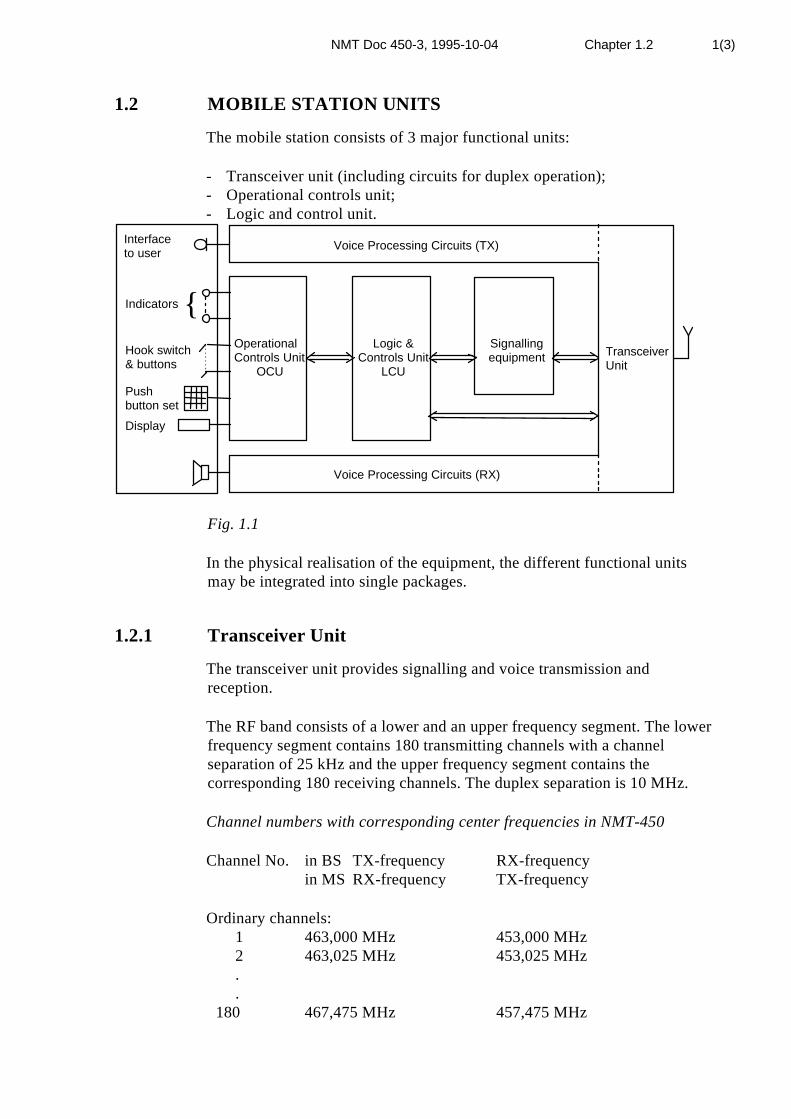
1.2 MOBILE STATION UNITS
The mobile station consists of 3 major functional units:
- Transceiver unit (including circuits for duplex operation);- Operational controls unit;- Logic and control unit.
Interfaceto user
Indicators
Hook switch& buttons
Pushbutton set
Display
Voice Processing Circuits (TX)
Voice Processing Circuits (RX)
TransceiverUnit
OperationalControls Unit
OCU
Logic &Controls Unit
LCU
Signallingequipment
Fig. 1.1
In the physical realisation of the equipment, the different functional unitsmay be integrated into single packages.
1.2.1 Transceiver Unit
The transceiver unit provides signalling and voice transmission andreception.
The RF band consists of a lower and an upper frequency segment. The lowerfrequency segment contains 180 transmitting channels with a channelseparation of 25 kHz and the upper frequency segment contains thecorresponding 180 receiving channels. The duplex separation is 10 MHz.
Channel numbers with corresponding center frequencies in NMT-450
Channel No. in BS TX-frequency RX-frequencyin MS RX-frequency TX-frequency
Ordinary channels: 1 463,000 MHz 453,000 MHz 2 463,025 MHz 453,025 MHz . . 180 467,475 MHz 457,475 MHz

NMT Doc 450-3, 1995-10-04 Chapter 1.2 2(3)
The LF output of the transceiver may be audio signals which are passed tothe Operational Controls Unit, or coded signalling information which ispassed to the Logic and Control Unit for decoding and appropriateprocessing.
1.2.2 Operational Controls Unit
The Operational Controls Unit provides the interface between the user andthe NMT-450-system. This functional unit, described in Chapter 3 and 4,includes a handset, push-button set, hands-free audio capability and allmobile station controls, indicators and tone signals with which the userinteracts.
1.2.3 Logic and Control Unit
The Logic and Control Unit, described in Chapter 5, functions as the mastercontrol for the mobile station and encodes and decodes the digital signallingused on the radio path and decides the appropriate action to be taken.
Some of the functions of the Logic and Control Unit are:
* Decoding orders from the MTX such as:- alerting the user to an incoming call (ringing order)- channel command- adjusting the transceiver output power- identity and authentication request- releasing the MS at completion of a call or forced release.- calculation in a dedicated security chip of SRES and B-key on basis of the
received RAND- encryption of the dialled digits based on the calculated B-key
* Receiving general identification signals from the MTX such as:- traffic area identification- calling channel identification- free traffic channel identification* Evaluating and ordering the necessary steps to be taken by the mobile
station
* Encoding the signalling information to the MTX such as:
- call initiation from MS (identification and authentication )- clearing signal when terminating a call- updating roaming information- dialled digits, encrypted or not, for call origination* Providing subscriber signalling information such as:- ringing signal- roaming alarm- malfunction alarm- service indicator- call received indicator

NMT Doc 450-3, 1995-10-04 Chapter 1.2 3(3)
1.2.4 Signalling equipment
The signalling equipment is described in Chapter 5 and NMT Doc 450-1.

NMT Doc 450-3, 1995-10-04 Chapter 1.3 1(10)
1.3 GENERAL CONDITIONS
1.3.1 General requirements
1.3.1.1 Marking of the equipment
The functions of all pilot lamps, terminals and controls as well as thepositions of the controls shall be clearly indicated on the equipment.
The equipment shall be clearly marked with the make, type designation andserial number. This rule shall apply also to the sample handed in for typeapproval.
The marking shall be mechanically firm and durable and may, for example,be made by means of engraving, embossing or application of a metal plate.
Furthermore, the Operational Controls Unit shall be provided with a platewhich shows the mobile telephone number.
The above mentioned markings will be subject to type approval, see Annex1.
1.3.1.2 Warming up period
At the latest one minute after having been switched on to the power supply,the equipment shall be fully ready for operation, which shall be taken tomean that all requirements laid down in these present specifications shall befulfilled.
1.3.2 Terminals
1.3.2.1 Test terminals
For test purposes the mobile station shall be provided with test terminals orother means e.g. supplementary unit, to make it possible to measure therequirements laid down in this specification.
1.3.2.2 Antenna terminal
The antenna terminal is the interface between the antenna and the mobilestation including the duplex filter.
1.3.2.3 Voice input and output terminals
The mobile station shall be provided with the necessary terminals for themeasurements specified in Chapter 2. Impedance's and signal levels at theseterminals shall be declared by the manufacturer.
NMT Doc 450-3, 1995-10-04 Chapter 1.3 2(10)
1.3.2.4 Arrangement for testing
It is required that the MS, inside the cabinet, shall be provided with anarrangement for test purposes which makes it possible to activate the MS inspeech condition on any of the radio channels. It shall only be accessible forservice and test personnel,
The arrangement shall overrule the autonomous time out device.
The method to be used to select a channel and activate the MS shall bedeclared by the manufacturer.
Reference is made to paragraph 4.5 and to Annex 19.
1.3.2.5 External equipment
External equipment may be connected to the MS via a separate interface unitand/or connector. See Annex 7 and Annex 18.
1.3.3 Test of the equipment
1.3.3.1 Application of the test conditions
For all requirements specified in these specifications, type approvalmeasurements shall be carried out under the normal test conditions describedin paragraph 1.3.4. If so specified, the test shall also be carried out under theextreme test conditions mentioned in paragraph 1.3.5.
1.3.3.2 Power supply
During the type approval tests, the power supply of the equipment shall bereplaced by an external power source capable of producing power supplyvoltages as described in paragraphs 1.3.4.2 and 1.3.5.2. The internalimpedance of the power source shall be low enough for its effect on the testresults to be negligible.
The power supply voltage shall be measured at the input terminals of theequipment.
If the equipment is provided with a permanently connected power cable, thepower supply voltage shall be measured at the point of connection of thepower cable to the equipment.

NMT Doc 450-3, 1995-10-04 Chapter 1.3 3(10)
In equipment with incorporated batteries, the power source shall be appliedas close to the battery terminals as practicable.
During the testing the power supply voltage shall be maintained within atolerance of ± 3% relative to the voltage at the beginning of the test.
1.3.4 Normal test conditions
1.3.4.1 Normal temperature and humidity
The normal temperature and humidity conditions for tests shall be anyconvenient combination of temperature and humidity within the followingranges:
Temperature +15°C to +35°C
Relative humidity 20% to 75%
1.3.4.2 Normal test power source
Mains voltage
The normal test voltage for equipment to be connected to the mains shall bethe nominal mains voltage. For the purpose of these specifications, thenominal voltage shall be the declared voltage or any of the declared voltagesfor which the equipment was designed.
Regulated lead-acid battery power sources of vehicles.
If the radio equipment is intended for operation from the usual types ofregulated lead-acid battery power source of vehicles, the normal test voltageshall be 1,1 times the nominal voltage of the battery (6 volts, 12 volts, etc.).
Other power sources.
For operation from other power sources or types of battery (primary orsecondary), the normal test voltage shall be that declared by the equipmentmanufacturer. The MS shall be protected against reversed polarity from thepower source.
1.3.5 Extreme test conditions
1.3.5.1 Temperatures at testing under extreme conditions
At testing under extreme conditions, the measurements shall be made inaccordance with paragraph 1.3.5.3 at the temperatures of -25°C and +55°C.
NMT Doc 450-3, 1995-10-04 Chapter 1.3 4(10)
1.3.5.2 Power supply voltages at testing under extreme conditions
Regulated lead-acid battery power supplies for use in motor vehicles
If the radio equipment is intended for operation from the usual types ofregulated lead-acid battery power supply of motor vehicles, measurementsshall be made at power supply voltages of 1,3 and 0,9 times the nominalvoltage of the battery (6 volts, 12 volts, etc.).
Mains voltage
The extreme test voltage for equipment to be connected to an AC mainssource shall be the nominal mains voltage ±10%.
Other power sources
The lower extreme test voltages for equipment with power sources usingprimary batteries shall be as follows:
1) For the Leclanché type of battery:
0,85 times the nominal voltage of the battery;
2) For the mercury type of battery:
0,9 times the nominal voltage of the battery;
3) For other types of primary batteries:
end point voltage declared by the equipment manufacturer.
For equipment using other power sources, or capable of being operated froma variety of power sources, the extreme test voltages shall be those agreedbetween the equipment manufacturer and the testing authority and shall berecorded with the results.
1.3.5.3 Procedure for tests at extreme temperatures
Test procedure
Before measurements are made, the equipment shall have reached thermalbalance in the test chamber. The equipment shall be switched off during thetemperature stabilising period. If the thermal balance is not checked bymeasurements, a temperature stabilising period of at least one hour, or such aperiod as may be decided by the testing authority, shall be allowed. Thesequence of measurements shall be chosen, and the humidity content in thetest chamber shall be controlled so that excessive condensation does notoccur.
Before tests at the upper temperature, the equipment shall be placed in thetest chamber and left until thermal balance is attained. The equipment shallthen be switched on in the transmit condition for a period of half an hourafter which the equipment shall meet the specified requirements.

NMT Doc 450-3, 1995-10-04 Chapter 1.3 5(10)
For tests at the lower temperature, the equipment shall be left in the testchamber until thermal balance is attained, then switched to the standby orreceive condition for a period of one minute, after which the equipment shallmeet the specified requirements.
1.3.5.4 Storage conditions
The mobile station shall withstand storage temperatures between -40°C and+70°C, for at least 24 hours without damage at each extreme temperature.The relative humidity at normal temperature is between 35 to 75 %.
1.3.6 Arrangement for test signals applied to the antennaterminal for receiver testing purposes
Sources of test signals connected to the antenna terminal shall be arranged insuch a way that the impedance presented is 50 ohms. This requirement shallalso be met if more than one signal source is applied simultaneously.
The levels of the test signals shall be expressed in terms of the E.M.F. at theantenna terminal.
1.3.7 Artificial antenna (dummy load)
Test of the transmitter shall be carried out with a non-radiating non-reactiveload of 50 ohms connected to the antenna terminal.
1.3.8 Test modulations
1.3.8.1 Normal test modulation
For normal test modulation, the modulation frequency shall be 1 kHz and theresulting frequency deviation shall be ±3,0 kHz. The test signal shall besubstantially free from amplitude modulation.
1.3.8.2 Data test modulation
Normal data test modulation is defined as the carrier frequency modulatedwith frame 15 (see NMT Doc 450-1) to give a mean frequency deviation of±3,5 kHz. This corresponds to peak deviation ±2,8 kHz for 1200 Hz and ±4,2kHz for 1800 Hz.
1.3.8.3 Supervisory signal modulation
Normal supervisory signal test modulation is defined as the carrier frequencymodulated with a signal of frequency 4015 Hz to give a frequency deviationof ±0,3 kHz.

NMT Doc 450-3, 1995-10-04 Chapter 1.3 6(10)
1.3.9 Definitions of some measuring instruments
1.3.9.1 Adjacent channel power measuring receiver
The receiver for measuring the adjacent channel power shall fulfil therequirements given in CEPT Recommendation T/R 24-01.
1.3.9.2 Psophometric filter
The psophometric filter, which is used when so stated in some of the testmeasurements, shall fulfil the requirements specified in CCITTRecommendation P53A (psophometer for commercial telephone circuits).
1.3.9.3 SINAD meter
The SINAD meter needed for receiver measurements is specified inCEPT Recommendation T/R 24-01. The psophometric filter needed forSINAD(P)-ratio measurements (see paragraph 2.3.7.1) may be includedin the SINAD meter.
1.3.10 Vibration test
The MS shall be tested together with the car cassette, if any, and withthe handset placed in the cradle. The cassette and the cradle shall befixed to the mounting table.
1.3.10.1 Vibration (Sweep)
a) It is required that the equipment is designed to withstand a vibration testaccording to the IEC publication 68-2-6.
10-55 Hz ±0,12 mm displacement
55-150 Hz 15 m/s2 acceleration.
Sweep rate: 1 octave per minute.
Duration: 2 hours in each 3 directions.
During the vibration test, the equipment shall not be in operation. After thetest, the equipment shall fulfil the requirements specified in these technicalspecifications.
b) Microphony test.It is required that the equipment is designed to prevent microphonic effects.
During this test the equipment shall be operating while it is vibratingbetween 55-150 Hz with an acceleration of 15 m/s2 and shall fulfil therequirements laid down in paragraphs 2.2.15 and 2.3.19. The microphone in

NMT Doc 450-3, 1995-10-04 Chapter 1.3 7(10)
the handset is made in-operative during this test. The microphone isdisconnected and replaced with a resistor equal to the resistance of themicrophone.
1.3.10.2 Vibration (Random), alternative test
a) It is required that the equipment is designed to withstand a vibration testaccording to IEC publication 68-2-36, test Fdb.
10 - 20 Hz 0,02 g2/Hz
20 - 150 Hz -3 dB/octave
Total r.m.s value (10 - 150 Hz) : 1 g
Duration: 1 hour in each 3 directions
During the vibration test, the equipment shall not be in operation. After thetest the equipment shall fulfil the requirements specified in these technicalspecifications.
b) Functional testIt is required that the equipment is designed to prevent microphonic effects.
During this test, the equipment shall be operating. The vibration level shallbe -6 dB relative the level stated in clause a).
The handset is removed from the vibration stand during this test.
The requirements are specified in paragraphs 2.2.15 and 2.3.19.
1.3.11 Test site and general arrangements for measurementsinvolving the use of radiated fields
1.3.11.1 Test site
The test site shall be on a reasonably level surface or ground.
At one point on the site, a ground plane of at least 5 metres in diameter shallbe provided. In the middle of this ground plane, a non conducting support,capable of rotation through 360° in the horizontal plane, shall be used tosupport the test sample at 1,5 metres above the ground plane. The test siteshall be large enough to allow the erection of a measuring or transmittingantenna at a distance of λ/2 or 3 metres whichever is the greater. Thedistance actually used shall be recorded together with the results of the testcarried out on the site.
Sufficient precautions shall be taken to ensure that reflections fromextraneous objects adjacent to the site, as well as ground reflections, do notdegrade the measurement results.

NMT Doc 450-3, 1995-10-04 Chapter 1.3 8(10)
1.3.11.2 Test antenna
When the site is used for radiation measurements, the test antenna is used todetect both the radiation from the test sample and the substitution antenna.This antenna is mounted on a support such as to allow the antenna to be usedin either horizontal or vertical polarisation and for the height of its centreabove ground to be varied over the range 1–4 metres. Preferably a testantenna with pronounced directivity should be used. The size of the testantenna along the measurement axis shall not exceed 20% of the measuringdistance.
For radiation measurements, the test antenna is connected to a testreceiver, capable of being tuned to any frequency under investigationand of measuring accurately the relative levels of signals at its input.
1.3.11.3 Substitution antenna
The substitution antenna shall be a λ/2 dipole, resonant at the frequencyunder consideration, or a shortened dipole, calibrated to the λ/2 dipole. Thecentre of this antenna shall coincide with the reference point of the testsample it has replaced. This reference point shall be the volume centre of thesample when its antenna is mounted inside the cabinet, or the point where anoutside antenna is connected to the cabinet.
The distance between the lower extremity of the dipole and the ground shallbe at least 30 cm.
The substitution antenna shall be connected to a calibrated signal generatorwhen the site is used for radiation measurements and to a calibratedmeasuring receiver when the site is used for measurement of receivercharacteristics. The signal generator and the receiver shall be operating at thefrequencies under investigation and shall be connected to the antennathrough suitable matching and balancing networks.
1.3.11.4 Alternative indoor site
When the frequency of the signals being measured is higher than 80 MHz, anindoor site may be used. If this alternative site is used, this shall be recordedin the test report.
The measurement site may be a laboratory room with a minimum area of 6metres by 7 metres and at least 2,7 metres in height. Apart from themeasuring apparatus and the operator, the room shall be as free as possiblefrom reflecting objects other than the walls, floor and ceiling.
An example of arrangements are shown in Fig.1.2

NMT Doc 450-3, 1995-10-04 Chapter 1.3 9(10)
Absorbentmaterial
Corner reflectorReference pointof test sample
Feeder to test receiver
0,75 m3 – 4 m
45°
λ/2 antenna
λ/2
h1 h2
Wall
h1 = h2
>0,6 m
≥ 1.35 m
≥ 1.35 m
Ceiling
Fig. 1.2 Indoor site arrangement (shown for horizontal polarisation)
The potential reflections from the wall behind the equipment under test arereduced by placing a barrier of absorbent material in front of it. The cornerreflector around the test antenna is used to reduce the effect of reflectionsfrom the opposite wall and from the floor and ceiling in the case ofhorizontally polarised measurements.
Similarly, the corner reflector reduces the effects of reflections from the sidewalls for vertically polarised measurements.
For the lower part of the frequency range (below approx. 175 MHz) nocorner reflector or absorbent barrier is needed.
For practical reasons, the λ/2 antenna may be replaced by an antenna ofconstant length, allowing it to be used at frequencies corresponding to alength between λ/2 and λ, as long as the sensitivity is sufficient. In the sameway, the distance of λ/2 to the apex may be varied.
The test antenna, test receiver, substitution antenna and calibrated signalgenerator are used in a way similar to that of the general method.
To ensure that errors are not caused by the propagation path approaching thepoint at which phase cancellation between direct and the remaining reflectedsignals occurs, the substitution antenna shall be moved through a distance of±10 cm in the direction of the test antenna as well as in the two directionsperpendicular to this first direction. If these changes of distance cause asignal change of greater than 2 dB, the test sample should be resited until achange of less than 2 dB is obtained.

NMT Doc 450-3, 1995-10-04 Chapter 1.3 10(10)
1.3.12 Receiver rated audio output power
The rated audio output power shall be the maximum power, declared by themanufacturer, for which all the requirements in clause 2.3 of thesespecifications are met. With normal test modulation, the audio output shallbe measured in a resistive load, simulating the load with which the receivernormally operates. The value of this load shall be declared by themanufacturer.

NMT Doc 450-3, 1995-10-04 Chapter 2.1 1(1)
2. TRANSCEIVER UNIT
2.1 GENERAL
The requirements in this chapter cover the transceiver unit consisting of thetransmitter/receiver, including circuits for duplex operation modulator/demodulator, pre-emphasis/de-emphasis networks, syllabic compandors,muting circuit and electroacoustic transducers with associated circuits.
The mobile station shall be equipped with syllabic compandors. (Reference:Recommendation G.162, CCITT IXth Plenary Assembly, Melbourne, 14-25November 1988, Blue Book, Vol. III. 1). The compression ratio shall be 2:1.The compressor part shall be located between the microphone circuits andthe pre-emphasis network, and the expander part shall be located betweenthe de-emphasis network and the handset earpiece (and loudspeaker) circuits.The manual volume control shall be located after the expander.

NMT Doc 450-3, 1995-10-04 Chapter 2.2 1(12)
2.2 TRANSMITTER
Unless otherwise specified, all requirements in section 2.2, shall be carriedout and fulfilled in conversation mode (duplex operation). The modulationsignal shall be applied to the voice input terminal of the transmitter, i.e. at apoint between the syllabic compressor stage and the pre-emphasis network,from an oscillator having a suitable impedance according to paragraph1.3.2.3. However, if provision is made for disabling the compressor, i.e.locking it to a fixed amplification, the test signal may be applied to a testpoint located before the compressor stage.
2.2.1 Frequency range and channel separation
The MS transmitter works on frequencies from 453,000 MHz to457,475 MHz, giving the corresponding MS receiver frequencies from463,000 MHz to 467,475 MHz.
2.2.1.1 Extension band (optional, subject to national regulations)
As an option the MS is allowed to work on the following frequencies:452.500-452.975 MHz; MS transmit,462.500-462.975 MHz; MS receive
2.2.2 Number of channels
The number of channels in the NMT-450-system is 180 channels. ChannelNo.1 is the lowest in frequency (in transmitter 453,000 MHz, in receiver463,000 MHz) and channel No.180 is the highest in frequency (in transmitter457,475 MHz, in receiver 467,475 MHz).
2.2.2.1 Extension band (optional, subject to national regulations)
The number of channels in the extension band is 20. Channel No. 181is the lowest in frequency (in receiver 462,500 MHz, in transmitter452,500 MHz) and channel No. 200 is the highest in frequency (inreceiver 462,975 MHz, in transmitter 452,975 MHz).
2.2.3 Frequency error2.2.3.1 Definition
The frequency error of the transmitter is the difference between the measuredcarrier frequency and its nominal value.

NMT Doc 450-3, 1995-10-04 Chapter 2.2 2(12)
2.2.3.2 Method of measurement
The carrier frequency shall be measured without modulation and with theMS antenna terminal connected to an artificial antenna. The measurementsshall be made under normal and extreme test conditions.
2.2.3.3 Requirements
The frequency error of the transmitter steady-state frequency shall not exceed±2,5 kHz under normal as well as extreme test conditions
2.2.4 Transmitter carrier power
2.2.4.1 Definition
The transmitter carrier power is the mean power delivered to the artificialantenna during a radio frequency cycle, without modulation.
2.2.4.2 Method of measurement
The antenna terminal shall be connected to an artificial antenna, and thepower delivered to this artificial antenna shall be measured. Themeasurements shall be made under normal test conditions and under extremetest conditions.
2.2.4.3 Requirements
The available steady-state carrier output power at the antenna terminal intoan artificial antenna shall be within the range 15 W ±1.5 dB or optional 7 W± 1.5 dB at normal and extreme conditions. Regarding portable mobilestations and handheld mobile stations ref. is made to annex 2 and annex 3respectively.
2.2.4.4 Load test
The transmitter shall be submitted to load tests with continuous transmissionduring a period of 30 minutes.
- The change in the transmitter output power relative to actual output powerat 50 ohm load shall not exceed 2 dB during a load test when the MS isloaded with a resistive impedance giving a standing wave ratio of 2. The testshall be carried out under normal test conditions.
- Without being damaged, the MS shall withstand a load test when it isloaded with a resistive impedance giving a standing wave ratio of 2. The testshall be carried out under extreme test conditions.
Furthermore the MS shall withstand, without being damaged, a load testwhen the MS is loaded with an arbitrary load. This is done by leaving theantenna terminal open and by short circuiting it for at least one minute ineach case. For handheld mobile stations see Annex 3.

NMT Doc 450-3, 1995-10-04 Chapter 2.2 3(12)
2.2.5 Transmitter carrier power control
The transmitter shall be capable of changing the transmitter carrier outputpower as controlled by the Logic and Control Unit to -10 dB ± 3 dB(medium power) and -20 dB ± 3 dB (low power) relative to nominal carrieroutput power 15 W (high power) at normal and extreme test conditions.
2.2.6 Carrier on/off condition and carrier rise/decay time
Transmitter start-up time and transmitter awake time are defined in Chapter6.
2.2.7 Transmitter channel switching time
For definition, method of measurement and requirements, see Chapter 6.
2.2.8 Spurious emissions
2.2.8.1 Definition
Spurious emissions are emissions at frequencies other than those of thecarrier and sidebands associated with normal test modulation.
The level of spurious emissions shall be measured as:
a) their conducted power level in an artificial antenna;
b) their effective radiated power when radiated by the cabinet and structureof the equipment (also known as "cabinet radiation"), as well as the integralor carrier case antenna if applicable.
2.2.8.2 Method of measuring the conducted power level
Spurious emissions shall be measured as the power level of any discretesignal delivered into a 50 ohms load. This may be done by connecting theantenna terminal through an attenuator to a spectrum analyzer or selectivevoltmeter, or by monitoring the relative levels of the spurious signalsdelivered to an artificial antenna.
The transmitter shall be unmodulated and the measurements made over thefrequency range 100 kHz to 4000 MHz, except for the channel on which thetransmitter is intended to operate and its adjacent channels.
The measurements shall be repeated with the transmitter modulated withnormal test modulation.
The same measurements shall also be made when the MS transmitter is inreduced power mode.

NMT Doc 450-3, 1995-10-04 Chapter 2.2 4(12)
2.2.8.3 Method of measuring the effective radiated power
On a test site, fulfilling the requirements of paragraph 1.3.11, the sampleshall be placed at the specified height on a non-conducting support. Thetransmitter shall be operated at the carrier power as specified underparagraph 2.2.4, delivered to an artificial antenna without modulation.
Radiation of any spurious components shall be detected by the test antennaand receiver, over the frequency range 30-4000 MHz, except for the channelon which the transmitter is intended to operate and its adjacent channels.
At each frequency at which a component is detected, the sample shall berotated to obtain maximum response and the effective radiated power of thatcomponent shall be determined by a substitution measurement.
The measurements shall be repeated with the test antenna in the orthogonalpolarisation plane.
The measurements shall be repeated with the transmitter modulated bynormal test modulation.
2.2.8.4 Requirements
The following requirements shall be fulfilled during full and reduced powermodes.
The power of any spurious emission shall not exceed the values given below:
100 kHz to 1000 MHz 1000 MHz to 4000 MHz
Tx. Operating 0,25 µW 1 µW
Standby 2 nW 20 nW
2.2.9 Frequency deviation
The frequency deviation is the maximum difference between theinstantaneous frequency of the modulated radio frequency signal and theunmodulated carrier.
2.2.9.1 Maximum permissible frequency deviation without supervisorysignal
2.2.9.1.1 Definition
The maximum permissible frequency deviation without supervisory signal isthe maximum value of frequency deviation stipulated in these specifications.
2.2.9.1.2 Method of measurement
The frequency deviation shall be measured at the antenna terminal of the MSconnected to an artificial antenna, by means of a deviation meter capable of

NMT Doc 450-3, 1995-10-04 Chapter 2.2 5(12)
measuring the maximum deviation, including that due to any harmonics andintermodulation products which may be generated in the transmitter.
The modulation frequency without the supervisory signal shall be variedfrom 20 Hz to 25 kHz. The level of this test signal shall be 20 dB above thelevel of the normal test modulation.
During the test an unmodulated RF signal with a level of 60 dB (µV) E.M.F.is applied to the receiver input through the combining network.
2.2.9.1.3 Requirements
The maximum permissible frequency deviation shall be ±4,7 kHz.
2.2.10 Limiting characteristics of modulator
2.2.10.1 Definition
The limiting characteristics of the modulator expresses the capability of thetransmitter to be modulated close to the maximum permissible frequencydeviation as defined in paragraph 2.2.9.
2.2.10.2 Method of measurement
A test signal with a frequency of 1000 Hz and without the supervisory signalshall be applied to the voice input circuit of the transmitter.
The level shall be adjusted so that the frequency deviation is ±1,0 kHz. Thelevel is then increased by 20 dB and the frequency deviation is againmeasured. If the compressor is used as a combined compressor/limiter andthe compressor part cannot be disconnected for testing purposes, the audiopressure shall be increased by 40 dB.
The measurements shall be carried out under normal test conditions andextreme test conditions.
During the test an unmodulated RF signal with a level of 60 dB (µV) E.M.F,is applied to the receiver input through the combining network.
2.2.10.3 Requirements
The frequency deviation shall be between ±3,7 kHz and ±4,7 kHz.
2.2.11 Adjacent channel power
2.2.11.1 Definition
The adjacent channel power is that part of the total power output of atransmitter under defined conditions of modulation, which falls within thebandwidth of a receiver of the type normally used in the system andoperating in either of the adjacent channels. This power is the sum of the

NMT Doc 450-3, 1995-10-04 Chapter 2.2 6(12)
mean power produced by the modulation, hum and noise of the transmitter.The adjacent channel is separated 25 kHz from the nominal frequency.
2.2.11.2 Method of measurement
The adjacent channel power shall be measured with a power-measuringreceiver which conforms to paragraph 1.3.9.1.
The transmitter shall be operated at full carrier power determined inparagraph 2.2.4 under normal test conditions. The antenna terminal shall belinked to the input of the "receiver" by a connecting device such that theimpedance presented to the MS is 50 ohms and the level at the "receiver"input is appropriate.
The transmitter shall be simultaneously modulated with a signal of 1250 Hzand the supervisory signal (4015 Hz) with ±0,3 kHz deviation.
During the test an unmodulated RF signal with a level of 3 to 100 dB (µV)E.M.F. is applied to the antenna terminal.
The signal of 1250 Hz shall be adjusted to a level 20 dB higher than thatrequired to produce ±3,0 kHz deviation (without supervisory signal). The"receiver" shall be tuned to the nominal frequency of the transmitter and thevariable attenuator in the "receiver" shall be adjusted to a value p dB suchthat a meter reading of the order of 5 dB above the "receiver" noise level isobtained.
The "receiver" shall then be tuned to the nominal frequency of one of theadjacent channels (25 kHz up or down) and the variable attenuator shall beadjusted to a value q dB such that the same meter reading is obtained.
The ratio of adjacent channel power to carrier power is the differencebetween the attenuator settings p and q. The adjacent channel power isdetermined by applying this ratio to the carrier power.
The measurement shall be repeated with normal data test modulation as inparagraph 1.3.8.2.
The measurements shall be repeated on the other adjacent channel. Themeasurement shall be repeated using all the power levels mentioned inparagraph 2.2.5.
2.2.11.3 Requirements
The adjacent channel power shall not exceed the power level correspondingto 70 dB below the actual power of the transmitter, or 0,2 microwatt atreduced output power.

NMT Doc 450-3, 1995-10-04 Chapter 2.2 7(12)
2.2.12 Audio-frequency response of the transmitter
2.2.12.1 Definition
The audio-frequency response is the frequency deviation of the transmittercarrier as a function of modulation frequency at constant level of themodulation signal.
2.2.12.2 Method of measurement
A modulation signal at a frequency of 1000 Hz is applied to the voice inputcircuit. Its amplitude is adjusted to such a level that a frequency deviation of±1 kHz is obtained. The frequency deviation is measured while thefrequency of the modulation signal is varied between 150 Hz and 25 kHz, itslevel being kept constant at the same value as at 1000 Hz. The measurementshall be made without the supervisory signal.
During the test an unmodulated RF signal with a level of 60 dB (µV) E.M.F.is applied to the receiver input through the combining network.
2.2.12.3 Requirements
The audio frequency response shall have a 6 dB/octave pre-emphasisbetween 300 Hz to 3400 Hz. Higher and lower frequencies shall beattenuated.
The tolerances are given in Fig. 2.2

NMT Doc 450-3, 1995-10-04 Chapter 2.2 8(12)
+10
Freq.deviationref. 1000 Hz
0
-10
-20
-
-
12 dB/octave
200 300 500 1000 2000 3000 40003400
f Hz- -
3 dB
1 dB
1 dB
3 dB
3 dB
6 dB/octave
18 dB/octave
4 kHz notch filteraccording to para 2.4.3
-
dB
Fig. 2.2 Audio frequency response of transmitter
2.2.13 Harmonic distortion factor in transmission
2.2.13.1 Definition
The harmonic distortion factor of a transmitter modulated by anaudio-frequency signal is defined as the ratio expressed as a percentage ofthe r.m.s. voltage of all the harmonic components of the fundamental audiofrequency to the total r.m.s. voltage of the signal after linear demodulation.
With the method described below, when a distortion analyzer is used, thehum and noise components are included in the distortion measurement.
2.2.13.2 Method of measurement
The radio frequency signal produced by the transmitter is applied, by meansof a suitable coupler, to a linear demodulator equipped with a de-emphasisnetwork of 6 dB per octave above 300 Hz. The response of this network maybe flat but not falling below 300 Hz. At normal test conditions, this radiofrequency signal is modulated successively at frequencies of 300, 500 and1000 Hz with a constant modulation index of 3 (the modulation index is theratio of the frequency deviation to the modulating frequency) producing 3.0kHz deviation at the frequency of 1000 Hz.

NMT Doc 450-3, 1995-10-04 Chapter 2.2 9(12)
The harmonic distortion factor of the audio frequency signal is measured atextreme test conditions at 1000 Hz with a frequency deviation of ±3,0 kHz.
During the test an unmodulated RF signal with a level of 60 dB (µV) E.M.F.is applied to the receiver input through the combining network.
2.2.13.3 Requirements
The harmonic distortion shall not exceed 5%.
2.2.14 Relative audio-frequency intermodulation product levelof the transmitter
2.2.14.1 Definition
The relative intermodulation-product level of the transmitter is the ratio,expressed in decibels, of
the level of an unwanted component of the output signal caused by thepresence of two modulating signals as a result of non linearity in thetransmitter
to
the level of one of the wanted output signals measured at the output of adeviation meter.

NMT Doc 450-3, 1995-10-04 Chapter 2.2 10(12)
2.2.14.2 Method of measurement
a) Connect the equipment as shown in Fig. 2.3
1. Audio-frequency generator no. 12 . Audio-frequency generator no. 23 . Audio-frequency combining unit4. MS transmitter under test5. Artificial antenna (50 ohm load)6 . Coupler/attenuator7. Deviation meter8. Audio-frequency spectrum analyzer or
selective voltmeter
Fig. 2.3
b) In the absence of an output from audio-frequency generator (2), adjust theaudio frequency generator (1) to produce ±2,3 kHz frequency deviation at amodulating frequency, F1, of 1000 Hz.
Record the output level of the audio-frequency signal generator.
c) Reduce the output of generator (1) to zero and adjust the output ofgenerator (2) to produce ±2,3 kHz frequency deviation at a modulatingfrequency: F2, of 1600 Hz.
d) Restore the output of generator (1) to the level recorded according to b)and measure the relevant intermodulation products with the selectivevoltmeter.
Note: The deviation meter shall be provided with a de-emphasis network of6 dB per octave.
During the test an unmodulated RF signal with a level of 60 dB (µV) E.M.F.is applied to the receiver input through the combining network.
2.2.14.3 Requirements
The relative intermodulation product level shall not exceed -20 dB relative toF2.
NMT Doc 450-3, 1995-10-04 Chapter 2.2 11(12)
2.2.15 Residual modulation
2.2.15.1 Definition
The residual modulation of the transmitter is the ratio, expressed in dB, ofthe audio frequency noise level produced after radio frequency signaldemodulation in the absence of modulation by the wanted signal, by thespurious effects of the power supply system, by the modulator or by othercauses, to the audio frequency level produced by normal test modulationapplied to the transmitter.
2.2.15.2 Method of measurements
a) The normal test modulation is applied to the transmitter. The RF signalproduced by the transmitter is applied by means of a suitable coupler to alinear demodulator.
The demodulator is equipped with a de-emphasis network of 6 dB per octave.
All precautions shall be taken to prevent the measurement results from beingaffected by emphasis at the low audio frequencies of the internal lineardemodulator noise.
Measurements shall be carried out on the demodulator output signal bymeans of an r.m.s. voltmeter equipped with a psophometric filter describedin paragraph 1.3.9.2.
The modulation is then removed and the level of the residualaudio-frequency output signal is again measured.
This test shall be repeated under conditions as specified in paragraph1.3.10 b.
b) The same method as a) above, but without the psophometric filter at theoutput.
In this case, the measurements are carried out by means of a peak-to-peakvoltmeter.
During the test an unmodulated RF signal with a level of 3 to 100 dB (µV)E.M.F. is applied to the antenna terminal.

NMT Doc 450-3, 1995-10-04 Chapter 2.2 12(12)
2.2.15.3 Requirements
For case a) the residual modulation shall not exceed -40 dB under normalconditions and -30 dB under conditions as specified in paragraph 1.3.10.b.
For case b) the residual modulation shall not exceed -20 dB under normalconditions and -14 dB under conditions as specified in paragraph 1.3.10.b.
2.2.16 Transmitter audio muting
2.2.16.1 Definition
An input muting device controlled by the Logic and Control Unit shall beprovided. The muting device shall prevent the voice input to causeinterference during the data transmission in the audio band.
2.2.16.2 Method of measurements
The measurements shall be performed in local mode.
A modulation signal at a frequency of 1000 Hz is applied to the voice inputcircuit. Its amplitude is adjusted to such a level that a frequency deviation of±3 kHz is obtained. The RF signal produced by the transmitter is applied bymeans of a suitable coupler to a linear demodulator. The demodulator isequipped with a de-emphasis network of 6 dB per octave.
The demodulated audio-frequency is measured by audio-frequency spectrumanalyzer. The audio-path from the device under test is then closed by localcommand and the modulation signal is kept on the same level and theattenuation is measured.
The test may be repeated at a modulation frequency where the audio noise islowest.
During the test an unmodulated RF signal with a level of 60 dB (µV) E.M.F.is applied to the antenna terminal.
2.2.16.3 Requirements
The muting shall be capable of causing at least 40 dB attenuation in theaudio path. The data transmission shall not begin until the muting hasreached an attenuation of 40 dB.
NMT Doc 450-3, 1995-10-04 Chapter 2.3 1(13)
2.3 RECEIVER
All requirements in section 2.3, with the exception of paragraph 2.3.14, shallbe fulfilled in duplex operation. The measurements shall be carried out inconversation mode at the voice output terminal of the receiver, i.e. at a pointbetween the de-emphasis network and the expander stage, by using a loadmentioned in paragraph 1.3.12. However, if provision is made for disablingthe expander, i.e. locking it to a fixed attenuation, the test point may belocated after the expander stage. The transmitter shall be modulated with a400 Hz tone giving a frequency deviation of ±3,0 kHz unless otherwisestated.
2.3.1 Frequency range and channel separation
The MS receiver works on frequencies from 463,000 MHz to467,475 MHz, with a channel separation of 25 kHz. The duplex separation is10 MHz, giving the corresponding MS transmitter frequencies from 453,000MHz to 457,475 MHz.
2.3.1.1 Extension band (optional, subject to national regulations)
As an option the MS is allowed to work on the following frequencies:452.500-452.975 MHz; MS transmit,462.500-462.975 MHz; MS receive
2.3.2 Number of channels
The number of channels in the NMT-450 is 180. Channel No. 1 is the lowestin frequency (in receiver 463,000 MHz, in transmitter453,000 MHz) and channel No. 180 is the highest in frequency (in receiver467,475 MHz, in transmitter 457,475 MHz).
2.3.2.1 Extension band (optional, subject to national regulations)
The number of channels in the extension band is 20. Channel No. 181 is thelowest in frequency (in receiver 462,500 MHz, in transmitter452,500 MHz) and channel No. 200 is the highest in frequency (in receiver462,975 MHz, in transmitter 452,975 MHz).
2.3.3 Duplex separation
The duplex receive channels are assigned on a one to one relationship withthe transmit channels, and a constant separation of 10 MHz.
2.3.4 Receiver detection and switching time
Definition, method of measurement and requirements are given in Chapter 6.

NMT Doc 450-3, 1995-10-04 Chapter 2.3 2(13)
2.3.5 Reduced channel locking capability
See paragraph 5.2.1.2
2.3.6 RF carrier detector
The detector level shall be fixed and the opening level shall be-2 dB (µV) E.M.F. ±2 dB at normal test conditions and-2 dB (µV) E.M.F. ±4 dB at extreme test conditions.
2.3.7.1 RF-sensitivity
2.3.7.1.1 Definition
The sensitivity of the receiver is the minimum RF-signal level at the antennaterminal which, at the nominal frequency of the receiver and modulated withnormal test modulation, will produce a power at the voice output circuit atleast 50% of the rated output power and a SINAD-ratio of 20 dB measuredthrough the psophometric filter (see paragraph 1.3.9.2).
The SINAD-ratio is the ratio of signal+noise+distortion to noise+distortion.The SINAD(P)-ratio is the SINAD-ratio measured through the psophometricfilter.
2.3.7.1.2 Method of measurements
A signal at the nominal frequency of the receiver and with normal testmodulation shall be applied to the antenna terminal. The SINAD meter (seeparagraph 1.3.9.3) and a psophometric filter shall be connected to the voiceoutput circuit. Where possible, the receiver volume control shall be adjustedto give 50% of the rated output power and, in the case of stepped volumecontrols, to the first step that provides an output power of at least 50% of therated output power.
The test signal input level at the antenna terminal shall be 0 dB(µV) E.M.F.under normal test conditions and +3 dB(µV) E.M.F. under extreme testconditions. In both cases the SINAD(P)-ratio is measured.
Under extreme test conditions, a variation of the receiver output power of±3 dB from the value obtained under normal test conditions may be allowed.
2.3.7.1.3 Requirements
The SINAD(P)-ratio shall be at least 20 dB in both cases. The maximumRF-signal level difference between any arbitrary channel to get the sameSINAD(P)-ratio shall not exceed 2 dB at normal test conditions and 3 dB ateach extreme test condition.

NMT Doc 450-3, 1995-10-04 Chapter 2.3 3(13)
2.3.7.2 Receiver duplex sensitivity degradation
2.3.7.2.1 Definition
Receiver duplex sensitivity degradation is a reduction of the receiversensitivity when the transmitter is switched on.
2.3.7.2.2 Method of measurement
The MS shall be in the condition of receiving ringing order. The referencesignal level, E0 is the lowest signal level when the MS generates ringinglocally as a response to 5a (L=9) with 95% reception probability. The MSshall then be in the speech condition and the lowest signal level for asuccessful switching call in progress, ES, shall be noted. The level ES is thelowest signal level for which switching call in progress is successful with95% probability during speech condition. The difference, ES - E0, in dB is ameasure of the receiver duplex sensitivity degradation.
The measurement is carried out with a VSWR 1:2.
2.3.7.2.3 Requirements
The receiver duplex sensitivity degradation shall not exceed 3 dB for alltransmitter output levels.
2.3.8 Co-channel rejection
2.3.8.1 Definition
The co-channel rejection is a measure of the capability of the receiver toreceive a wanted modulated signal without exceeding a given degradationdue to the presence of an unwanted modulated signal, both signals being atthe nominal frequency of the receiver.
2.3.8.2 Method of measurement
Two input signals shall be connected to the antenna via a combining device.The wanted signal shall have normal test modulation. The unwanted signalshall be modulated with a frequency of 400 Hz with a deviation of ±3 kHz.Both input signals shall be at the nominal frequency of the receiver and themeasurement repeated for displacements of the unwanted signal of up to±3 kHz.
The transmitter shall be unmodulated during the test.
Initially the unwanted signal shall be switched off and the level of the wantedsignal shall be adjusted to 3 dB (µV) E.M.F. The unwanted signal shall thenbe switched on.
The level of the unwanted signal shall be adjusted until the SINAD(P)-ratiomeasured at the voice output circuit is reduced to 20 dB.

NMT Doc 450-3, 1995-10-04 Chapter 2.3 4(13)
The co-channel rejection ratio is expressed as the ratio in dB of the level ofthe unwanted signal to the level of the wanted signal at the antenna terminalfor which a SINAD(P)-ratio = 20 dB at the voice output circuit occurs.
2.3.8.3 Requirements
The co-channel rejection ratio at any of the specified signal displacementsshall be between 0 dB and -8 dB.
2.3.9 Adjacent channel selectivity
2.3.9.1 Definition
The adjacent channel selectivity is a measure of the capability of the receiverto receive a wanted modulated signal without exceeding a given degradationdue to the presence of an unwanted signal which differs in frequency fromthe wanted signal by an amount equal to the channel separation. Theadjacent channel is separated 25 kHz from the nominal frequency.
2.3.9.2 Method of measurement
Two signals shall be applied to the antenna terminal via a combining device.The wanted signal shall be tuned to the nominal frequency of the receiverand be modulated with normal test modulation. The unwanted signal shall beat the nominal frequency of the upper adjacent channel (+25 kHz) and bemodulated with a 400 Hz tone to a frequency deviation of ±3 kHz.
The mobile station transmitter shall be unmodulated during the test.
Initially the unwanted signal shall be switched off and the level of the wantedsignal shall be adjusted to 3 dB (µV) E.M.F. under normal test conditionsand 6 dB (µV) E.M.F. under extreme test conditions. The unwanted signalshall then be switched on and its level adjusted until the SINAD(P)-ratiomeasured at the voice output circuit is reduced to 20 dB.
The measurement shall be repeated with the unwanted signal at the nominalfrequency of the lower adjacent channel (-25 kHz).
The ratios expressed in dB of the level of the unwanted signal to the level ofthe wanted signal are determined. The adjacent channel selectivity shall thenbe the lower value of the two ratios.
2.3.9.3 Requirements
The adjacent channel selectivity shall not be less than 70 dB under normaltest conditions and not less than 60 dB under extreme test conditions.

NMT Doc 450-3, 1995-10-04 Chapter 2.3 5(13)
2.3.10 Adjacent channel selectivity in the interleaved channel(12,5) kHz (NOT IN NMT 450 SYSTEM)
2.3.11 Spurious response rejection
2.3.11.1 Definition
The spurious response rejection is a measure of the capability of the receiverto discriminate between the wanted modulated signal at the nominalfrequency and an unwanted signal at any other frequency than the wantedand adjacent channels.
2.3.11.2 Method of measurement
Two input signals shall be applied to the antenna terminal via a combiningdevice. The wanted signal shall be at the nominal frequency of the receiverand be modulated with normal test modulation.
Initially the unwanted signal shall be switched off and the wanted inputsignal adjusted to 3 dB (µV) E.M.F. The unwanted signal shall be switchedon and modulated with a 400 Hz tone to a frequency deviation of ±3 kHz.The input level of the unwanted signal shall be 83 dB (µV) E.M.F. Thefrequency shall then be varied over the frequency range from 100 kHz to2000 MHz.
At any frequency at which a response is obtained, the input level of theunwanted signal shall be adjusted until the SINAD(P)-ratio of the voiceoutput circuit is reduced to 20 dB.
The spurious response rejection is expressed as the ratio in dB of the inputvoltage of an unwanted signal and the input voltage of the wanted signalwhen SINAD(P)-ratio of 20 dB, as mentioned above, is obtained.
The transmitter shall be unmodulated during the test.
2.3.11.3 Requirements
The spurious response rejection shall be at least 70 dB.
2.3.12 Intermodulation rejection
2.3.12.1 Definition
The intermodulation rejection is a measure of the capability of the receiver toreceive a wanted signal without exceeding a given degradation due to thepresence of two unwanted high level signals. One channel separation equals25 kHz.
2.3.12.2 Method of measurement
Three signals shall be applied to the antenna terminal via a combiningdevice. The wanted signal A shall be tuned to the nominal frequency of the

NMT Doc 450-3, 1995-10-04 Chapter 2.3 6(13)
receiver and modulated to normal test modulation. The unwanted signal Bshall be tuned to a frequency 50 kHz above the nominal frequency of thewanted signal and shall be unmodulated. The unwanted signal C shall betuned to a frequency 100 kHz above the frequency of the wanted signal andbe modulated with a 400 Hz tone to a frequency deviation of ± 3 kHz.
The level of the wanted signal A shall be adjusted to 3 dB (µV) E.M.F. Thelevel of the two unwanted signals B and C shall be maintained equal andincreased in level until the SINAD(P)-ratio measured at the voice outputcircuit is 20 dB.
The frequencies of signals B and C may be slightly adjusted to get maximumdegradation of the SINAD(P)-ratio and their levels adjusted until theSINAD(P)-ratio is again 20 dB.
The measurement shall be repeated with the two unwanted signals B and Ctuned to 50 kHz and 100 kHz, respectively, below the frequency of thewanted signal.
The intermodulation rejection is expressed as the level in dB of the unwantedsignals and the wanted signal when the SINAD(P)- ratio of 20 dB asmentioned above, is obtained. The transmitter shall be unmodulated duringthe test.
2.3.12.3 Requirements
The intermodulation rejection shall not be less than 67 dB.
2.3.13 Blocking
2.3.13.1 Definition
Blocking is a change (generally a reduction) in the wanted output power of areceiver or a reduction of the SINAD(P)-ratio due to an unwanted signal onanother frequency.
2.3.13.2 Method of measurement
Two input signals shall be applied to the antenna terminal via a combiningdevice. The wanted signal shall be at the nominal frequency of the receiverand shall have normal test modulation. Initially the unwanted signal shall beswitched off and the input level of the wanted signal adjusted to 3 dB (µV)E.M.F.
Where possible, the output power of the wanted signal at the voice outputcircuit shall be adjusted to 50% of the rated output power and in the case ofstepped volume controls to the first step that provides an output power of atleast 50% of the rated output power. Then the unwanted signal is switchedon. The unwanted signal shall be unmodulated, and the frequency shall bevaried between +1 MHz and +10 MHz, and also between -1 MHz and-10 MHz, relative to the nominal frequency of the receiver. The input level

NMT Doc 450-3, 1995-10-04 Chapter 2.3 7(13)
of the unwanted signal, at all frequencies in the specified ranges, shall beadjusted such that the unwanted signal causes:
a) a reduction of 3 dB in the audio frequency output power of the wantedsignal, or
b) a reduction of the SINAD(P)-ratio to 20 dB which ever occurs first.
This input level is the blocking level at the frequency concerned. The mobilestation transmitter shall be unmodulated during the test.
2.3.13.3 Requirements
The blocking level for any frequency within the specified ranges shall not beless than 90 dB (µV) E.M.F. except at frequencies where spurious responsesare found.
2.3.14 Spurious emissions
2.3.14.1 Definition
Spurious emissions are any emissions from the receiver and the transmitter incarrier "off" condition.
The level of spurious emissions shall be measured as:
a) their conducted power level in an artificial antenna
and
b) their effective radiated power when radiated by the cabinet and structureof the equipment (also known as "cabinet radiation"), as well as the integralor carrier case antenna if applicable.
2.3.14.2 Method of measuring the conducted power
Conducted spurious emissions shall be measured as the power of any discretesignal at the antenna terminal of the mobile station. The antenna terminal isconnected to a spectrum analyser or selective voltmeter having an inputimpedance of 50 ohms and the receiver is switched on.
If the measuring receiver is not calibrated in terms of absolute power, thepower of any detected components shall be determined by a substitutionmethod using a signal generator.
The measurements shall be carried out within at least the frequency range100 kHz to 4000 MHz.
2.3.14.3 Method of measuring the effective radiated power
On a test site fulfilling the requirements of paragraph 1.3.11, the sample shallbe placed at the specified height on a non-conducting support. The receiver
NMT Doc 450-3, 1995-10-04 Chapter 2.3 8(13)
shall be operated from a power source via a radio-frequency filter to avoidradiation from the power leads. The antenna terminal shall be connected to a50 ohms resistive load. Radiation of any spurious components shall bedetected by the test antenna and measuring receiver over the frequency rangefrom 30 MHz to 4000 MHz.
At each frequency at which a spectral component is detected, the sampleshall be rotated to obtain maximum response and the effective radiatedpower of that component shall be determined by a substitution measurement.
The measurement shall be repeated with the test antenna in the orthogonalpolarisation plane.
2.3.14.4 Requirements
The power of any spurious emission in the range 100 kHz to 1000 MHz shallnot exceed 2 nW, and in the range 1000 MHz to 4000 MHz shall not exceed20 nW.
2.3.15 Harmonic distortion ratio
2.3.15.1 Definition
The harmonic distortion ratio at the voice output circuit is the r.m.s. value ofthe voltage of all harmonics divided by the r.m.s. value of the total signalvoltage.
2.3.15.2 Method of measurement
Test signal of 60 dB (µV) E.M.F. and 100 dB (µV) E.M.F. at the nominalfrequency of the receiver shall be applied successively to the antennaterminal.
At each measurement the volume control of the receiver shall be set in such amanner that the power at the voice output circuit is equal to the rated outputpower of the receiver.
The test signal shall be modulated successively with 300, 500 and 1000 Hztones to frequency deviations of ±0,9 kHz, ±1,5 kHz and ±3,0 kHzrespectively.
Under extreme test conditions tests shall be carried out at the nominalfrequency of the receiver as well as ±1 kHz from the nominal frequency. Inthis case, the input signal is modulated only with a 1000 Hz tone to afrequency deviation of ±3,0 kHz. The transmitter shall be unmodulatedduring the test.

NMT Doc 450-3, 1995-10-04 Chapter 2.3 9(13)
2.3.15.3 Requirements
At all audio frequencies used in the measurement and under all testconditions, the harmonic distortion ratio shall not exceed 5%.
2.3.16 Relative audio frequency intermodulation product level
2.3.16.1 Definition
The relative intermodulation product level is the ratio, expressed in dB, ofthe level of an unwanted component of the output signal caused by thepresence of two modulating signals as a result of non linearity in thereceiver, to the level of one of the wanted output signals measured at thevoice output circuit.
2.3.16.2 Method of measurement
Two audio frequency generators, A and B, shall be connected via acombining device to the modulation input of the radio frequency signalgenerator.
Adjust the radio-frequency test signal to the nominal frequency of thereceiver and the test signal level successively to 20 dB, 60 dB and 100 dB(µV) E.M.F.
In the absence of an output from audio-frequency generator B, adjust theaudio-frequency generator A to produce a ±2,3 kHz frequency deviation at amodulation frequency of 1000 Hz. Where possible, adjust the output powerto 50% of the rated output power. In case of stepped volume controls, thefirst step that provides an output power of at least 50% of the rated outputpower, shall be used. Record the output level of generator A.
Reduce the output of generator A to zero and adjust the output of generator Bto produce a ±2,3 kHz frequency deviation at a modulation frequency of1600 Hz.
Restore the output of generator A to the level recorded and measure the levelof the 1600 Hz component and of the intermodulation products at the voiceoutput circuit.
The transmitter shall be unmodulated during the test.
2.3.16.3 Requirements
The relative audio frequency intermodulation product level shall not exceed-20 dB relative to 1600 Hz.
2.3.17 Amplitude characteristics of the receiver limiter
2.3.17.1 Definition

NMT Doc 450-3, 1995-10-04 Chapter 2.3 10(13)
The amplitude characteristics of the receiver limiter is the relationshipbetween the level of a specified modulated input signal and the level of theaudio frequency signal at the output of the receiver.
2.3.17.2 Method of measurement
A signal at the nominal frequency of the receiver with normal testmodulation and at a level of 3 dB (µV) E.M.F. shall be applied to theantenna terminal. Where possible the audio frequency output power shall beadjusted to 25% of the rated output power. In case of stepped volume controlthe first step that provides an output power of at least 25% of the rated outputpower shall be used. The input signal shall be increased to 100 dB (µV)E.M.F. and the audio frequency output power shall be measured again.
2.3.17.3 Requirements
At the change in the input power specified above, the change in the outputpower shall not exceed 3 dB.
2.3.18 AM-suppression
2.3.18.1 Definition
AM-suppression is the capability of the receiver to suppress amplitudemodulated signals. It is expressed as the ratio in dB of the audio power atthe voice output circuit with normal test modulation to the audio power witha specified amplitude modulation.
2.3.18.2 Method of measurement
A test signal at a level of 20 dB (µV) E.M.F. and 60 dB (µV) E.M.F. at thenominal frequency of the receiver shall be applied to the antenna terminalsuccessively. The signal shall initially have normal test modulation and thereceiver output power shall be set to the nominal output level. The normaltest modulation shall then be replaced by amplitude modulation to 30% witha 1000 Hz tone. The audio power shall be measured again. It may benecessary to make this measurement with a selective voltmeter.
2.3.18.3 Requirements
The AM-suppression shall not be less than 30 dB.
2.3.19 Noise and hum
2.3.19.1 Definition
The "noise and hum" of the receiver is the ratio, expressed in dB, of theaudio frequency noise and hum level resulting from the spurious effects ofthe power supply system or from other causes to the audio frequency powerproduced by a medium-level RF signal modulated by normal test modulationapplied to the antenna terminal.

NMT Doc 450-3, 1995-10-04 Chapter 2.3 11(13)
2.3.19.2 Method of measurement
A test signal at a level of 30 dB (µV) E.M.F. at a carrier frequency equal tothe nominal frequency of the receiver and modulated to the normal testmodulation, is applied to the antenna terminal. A psophometric filter isconnected to the voice output circuit. The audio frequency output powercontrol, if any, shall be adjusted to the rated output power.
This test shall be repeated under vibration, paragraph 1.3.10b.
The output signal is measured by an r.m.s. voltmeter.
The modulation is then removed and the audio frequency output levelmeasurement is repeated.
The measurement shall be repeated using the same method as above butwithout the psophometric filter.
The output signal is measured by means of a peak-to-peak voltmeter.
2.3.19.3 Requirements
With the psophometric filter, the receiver "noise and hum" ratio shall notexceed -40 dB under normal test conditions and -30 dB under conditions asspecified in paragraph 1.3.10.b.
Without the psophometric filter, the receiver "noise and hum" ratio shall notexceed -20 dB under normal test conditions, and -14 dB under conditions asspecified in paragraph 1.3.10.b.
2.3.20 Audio frequency response
2.3.20.1 Definition
The audio frequency response of the receiver expresses the variations of theaudio frequency output level as a function of the input signal modulationfrequency at the input.
2.3.20.2 Method of measurement
A test signal of 60 dB (µV) E.M.F at a frequency equal to the nominalfrequency of the receiver is applied to the antenna terminal. A test signalshall have normal test modulation.
Where possible, the output power shall be adjusted to 50% of the ratedoutput power. In case of stepped volume control, the first step that providesan output power of at least 50% of the rated output power shall be used. Thissetting is not altered during the test.

NMT Doc 450-3, 1995-10-04 Chapter 2.3 12(13)
The frequency deviation at 1000 Hz is then reduced to ±1 kHz.
The frequency deviation is maintained constant while the modulationfrequency is varied between 20 and 5000 Hz.
The measurement is repeated with a test signal having a frequency equal tothe nominal RF frequency of the receiver plus or minus 1,0 kHz.
The transmitter shall be unmodulated during the test.
2.3.20.3 Requirements
The audio level relative to the value at 1 kHz at constant frequency deviationshall be as given in Fig.2.4.
-30
-20
-10
0
+10
500 1000 2000 400030003400
300200
8 dB
6 dB/octave
4 kHz notch filterbandwidth ±55 Hz
f Hz
dB
Output levelref. 1000 Hz
3 dB
1 dB
1 dB
3 dB
20
Fig. 2.4 Receiver audio output level as a function of modulation frequencyat constant frequency deviation

NMT Doc 450-3, 1995-10-04 Chapter 2.3 13(13)
2.3.21 Receiver audio muting
2.3.21.1 Definition
An output muting device controlled by the Logic and Control Unit shall beprovided. The device mutes data signals measured at the voice outputterminal of the receiver. See clause 5.5.4.
2.3.21.2 Method of the measurement
The MS is in NMT-mode. Initiate a call. In conversation state a test signal ata level of 60 dB (µV) E.M.F. modulated with normal test modulation, isapplied to the antenna terminal. A psophometric filter is connected to thevoice output circuit . The audio frequency power control, shall be adjusted tothe rated output power.
The output signal is measured by an r.m.s. voltmeter.
The modulation is then replaced by continues FFSK signalling (idle frame 6,less than 30 sec) and the audio output level measurement is repeated.
Connect the digital storage oscilloscope to the voice output circuit.
The FFSK signalling is then replaced by normal test modulation. The timefrom the end of the last frame sync until opening of audio path is measured.Check that the muting device is not reacting upon "signals" which are -18 dB± 3 dB below the nominal data signal The call is terminated and the audiooutput level measurement is repeated on the calling channel. During thismeasurement the expander shall not be disabled.
2.3.21.3 Requirement
The muting of the data signals measured at the voice output terminal of thereceiver shall be minimum 50 dB.The requirement shall be fulfilled both in standby and conversation.Opening of the audio path is delayed 277 ± 10 ms after reception of the lastframe synchronization.

NMT Doc 450-3, 1995-10-04 Chapter 2.4 1(7)
2.4 ∅∅-SIGNAL LOOP AND TRANSCEIVER COUPLING
2.4.1 Supervisory signal deviation
2.4.1.1 Definition
The supervisory signal (∅-signal) as received and demodulated in thereceiver is looped to the modulator without regeneration and shall produce atransmitter frequency deviation equal to the frequency deviation of thereceived supervisory signal.
2.4.1.2 Method of measurement
2.4.1.2.1 Calibration set up
A test signal at the normal frequency of the receiver shall be applied to themodulation analyzer. The signal shall be modulated with a 4000 Hz tone to afrequency deviation of ±300 Hz. The modulation analyzer output level shallbe measured.
1 RF signal generator2 Modulation analyzer3 Selective voltmeter4 LF generator
Fig. 2.5 Calibration set up
2.4.1.2.2 Measurement set up
Test signal of 10 dB (µV) E.M.F. and 90 dB (µV) E.M.F. at the nominalfrequency of the receiver shall be applied successively to the antennaterminal. The test signal shall be modulated successively with 3945, 4000and 4055 Hz tones to frequency deviation of ±300 Hz.
The modulation analyzer output level shall be measured selectively and berecorded.

NMT Doc 450-3, 1995-10-04 Chapter 2.4 2(7)
1 Device under test (MS)2 RF signal generator3 Modulation analyzer4 Selective voltmeter5 LF generator
10 dB
20dB
50Ω
Fig. 2.6 Measurement set up
2.4.1.3 Requirements
The transmitted supervisory signal (∅-signal) shall not exceed±300Hz ± 10 % deviation under all test conditions.
The supervisory signal deviation shall not be influenced by audio input.
Frequency = 4000 Hz continuous (±55 Hz).
2.4.2 Transceiver coupling
2.4.2.1 RX-TX
2.4.2.1.1 Definition
Any coupling from the receive path to the transmit path must be sufficientlysmall to prevent excessive echo from returning to the base station, asspecified in the following.
2.4.2.1.2 Method of measurement
The RF generator shall be modulated with a 1000 Hz tone giving a frequencydeviation of ± 1 kHz. This level shall not be changed during themeasurement. The compressor shall be disconnected.
During this measurement, the acoustic path between the handset receiver(earpiece) and microphone shall be blocked by connecting the handsetreceiver to an artificial ear.

NMT Doc 450-3, 1995-10-04 Chapter 2.4 3(7)
2.4.2.1.3 Requirements
The ratio in dB between the frequency deviation of the transmitter signal andthat of the received signal at any modulation frequency shall be attenuated inaccordance with fig. 2.7.
-10
-20
-25
-30
-35
Receiver - transmitter couplingdB
55 Hz 55 Hz
0
-6
0+ 1.0dB
- 1.0dB
1000 2000 30003200
34003800
40004200
5000 6000 HzModulation frequency
- -
-
-
Fig. 2.7
2.4.2.2 TX-RX
2.4.2.2.1 Definition
Any coupling from the transmit path to the receive path must be sufficientlysmall as specified in the following.

NMT Doc 450-3, 1995-10-04 Chapter 2.4 4(7)
2.4.2.2.2 Method of measurement
The transmitter shall be modulated with a 300 - 3400 Hz signal with constantlevel, giving a deviation of ±1 kHz at 1000 Hz. The variation of thedeviation in transmitter, and the output level of the receiver audio outputcircuits caused by the coupling from transmitter shall be recorded. A 60 dB (µV) E.M.F. unmodulated RF input signal shall be simultaneously fed to thereceiver input. The RF input signal shall then be modulated by a 300 - 3400Hz signal, and the deviation shall follow that obtained by the transmitter.The output signal at the receiver output circuit shall be recorded. The twoaudio levels shall be compared at corresponding frequencies. Thecompander shall be disconnected.
2.4.2.2.3 Requirements
The coupling between transmitter path to receiver path at the receiver outputshall be below -25 dB.
2.4.3 Interference in the ∅∅-signal frequency band
2.4.3.1 Definition
The interference level is the ratio, expressed in dB, of the level of unwantedcomponent of the output signal, caused by the presence of the modulation inthe received signal as a result of nonlinearity in the receiver and transmitter,to the level of the wanted ∅-signal measured at the output of the transmitter.
2.4.3.2 Method of measurement
The radio frequency signal produced by the transmitter is applied, by meansof a suitable coupler, to a linear demodulator equipped with a filter accordingto Fig. 2.8, and measured with an r.m.s. voltmeter. Alternatively an audiospectrum analyser may be used.
0
1,5
45dB 3800 3850 4000 4150 4200 Hz

NMT Doc 450-3, 1995-10-04 Chapter 2.4 5(7)
Fig. 2.8
A radio frequency signal at the nominal frequency of the receiver and with alevel of 60 dB (µV) E.M.F. is applied, by means of a suitable coupler, to thereceiver input terminal. The radio frequency signal is modulated with∅-signal to ±0,3 kHz deviation and the level of the looped ∅-signal ismeasured. Thereafter the ∅-signal modulation is removed.
a) The receiver input radio frequency signal is then modulated to ±1,5 kHzdeviation. The modulation frequency is varied between 300 Hz and3400 Hz. The interference in the looped ∅-signal channel is measured.
The measurement is repeated at the deviation 3 dB above and 3 dB below thetest modulation above.
The transmitter shall be unmodulated during the test.
b) An acoustic test tone with a frequency of 1000 Hz is applied to thehandset microphone. The level of the tone is adjusted so that a peakfrequency deviation of the RF-carrier of ±3 kHz is obtained.
Keeping the sound pressure at the microphone constant at its initiated levelthe frequency of the acoustic test signal is varied between 300 Hz and 5000Hz, and the interference in the looped ∅-signal channel is measured.
The receiver input radio frequency signal shall be unmodulated during thetest.
2.4.3.3 Requirements
The interference level in the looped ∅-signal channel shall not exceed incase a) -10 dB and in case b) -15 dB relative to the ∅-signal level.

NMT Doc 450-3, 1995-10-04 Chapter 2.4 6(7)
2.4.4 Relative audio frequency intermodulation product levelin the ∅∅-signal loop
2.4.4.1 Definition
The relative intermodulation product level is the ratio, expressed in dB, ofthe level of an unwanted component in the ∅-signal loop caused by thepresence of two modulating signals as a result of nonlinearity in the receiverand transmitter, to the level of the wanted ∅-signal measured at the output ofthe transmitter.
2.4.4.2 Method of measurement
The radio frequency signal produced by the transmitter is applied, by meansof a suitable coupler, to a linear demodulator equipped with a filter accordingto the figure below, and measured with an r.m.s. voltmeter. Alternatively anaudio spectrum analyser may be used.
0
1,5
45dB 3800 3850 4000 4150 4200 Hz
Fig. 2.9
A radio frequency signal at the nominal frequency of the receiver and with alevel of 60 dB (µV) E.M.F. is applied, by means of a suitable coupler, to thereceiver input terminal. The radio frequency signal is modulated with∅-signal to ±0,3 kHz deviation and the level of the looped ∅-signal ismeasured. Thereafter the ∅-signal modulation is removed.
Two audio frequency generators, A and B, shall be connected via acombining device to the modulation input of the radio frequency signalgenerator.
Adjust the radio-frequency test signal to the nominal frequency of thereceiver and the test signal level successively to 20 dB, 60 dB and 100 dB(µV) E.M.F.

NMT Doc 450-3, 1995-10-04 Chapter 2.4 7(7)
In the absence of an output from audio-frequency generator B, adjust theaudio-frequency generator A to produce a ±2,1 kHz frequency deviation at amodulation frequency of 1200 Hz. Where possible, adjust the output powerto 50 % of the rated output power. In case of stepped volume controls, thefirst step that provides an output power of at least 50 % of the rated outputpower, shall be used. Record the output level of generator A.
Reduce the output of generator A to zero and adjust the output of generator Bto produce a ±2,1 kHz frequency deviation at a modulation frequency of2800 Hz.
Restore the output of generator A to the level recorded and measure theintermodulation products in the looped ∅-signal channel.
The transmitter shall be unmodulated during the test.
2.4.4.3 Requirements
The intermodulation product level in the looped ∅-signal channel shall notexceed -10 dB relative to the ∅-signal level.

NMT Doc 450-3, 1995-10-04 Chapter 2.5 1(8)
2.5 VOICE PROCESSING REQUIREMENTS,TRANSMITTING
The CCITT Recommendations of the P-series referred to in this section arethose in CCITT Blue Book, Vol. V, IXth Plenary Assembly, Melbourne, 14-25 November 1988.
The measurements described in this section shall be performed in localmode. The antenna terminal of the mobile station shall be connected, bymeans of an attenuator/coupler, to an ideal base station represented by ameasuring set-up consisting of three parts (Fig. 2.10):
1: Deviation meter (modulation analyzer)
2: 6 dB/octave de-emphasis network
3: The expander part of a 2:1 syllabic compander with a nominal attacktime of 3.0 msec and a nominal recovery time of 13.5 msec. The compander shall meet the requirements in CCITT Rec. G.162.However, the compander parameters shall be calibrated to an accuracyin line with laboratory instruments.
Note: The expander stage of the ideal base station used for type approval bythe Nordic Administrations will be based on the circuit NE 570.
In section 2.5 the term "reference tone" shall mean a tone, transmittedthrough the system, with a frequency of 1000 Hz and producing a peakfrequency deviation of ±3 kHz. The term "reference level" shall, at anypoint, mean the level of the test tone at that point.
2 1attenuator/coupler
RX lin.demod de emph. expand.MS
Fig. 2.10 Measuring set-up, transmission
When measuring the mobile station with deactivated compander, theexpander circuit in point 3 above is bypassed.
The paragraphs below that do not apply when the compander is deactivated,are marked with (*).
NMT Doc 450-3, 1995-10-04 Chapter 2.5 2(8)
2.5.1* Compression linearity
2.5.1.1 Definition
The compression linearity is the deviation from the linear relation betweenthe input amplitude of the compressor and the output amplitude of an idealbase station.
2.5.1.2 Method of measurement
A test signal with a frequency of 1000 Hz shall be applied to a test point atthe input of the compressor stage of the mobile station. Its amplitude shall beadjusted to the reference level. The ratio D0 in dB between the amplitude ofthe input test signal and the amplitude at Point 1 of the measuring set-up inFig. 2.10 shall be measured. The input amplitude shall subsequently bevaried from +3 dB to -50 dB relative to its initial value. The ratio D betweenthe input and the output amplitudes shall be recorded as a function of inputamplitude.
Note: The compression ratio of the compressor of the mobile station is 2:1.This compression ratio is compensated by the expansion ratio of 1:2 of theexpander of the measuring set-up.
2.5.1.3 Requirements
The maximum difference between D and D0 shall be ±1,0 dB.
2.5.2* Transient response of the compressor
2.5.2.1 Definition
The definition of transient response shall be as in CCITT Rec. G.162, clause7.
2.5.2.2 Method of measurement
The transient response of the compressor shall be measured with a 12 dBstep of a test signal of 2000 Hz applied to the input of the compressor stageof the mobile station. The high and low level of the signal shall berespectively -22 dB and -34 dB relative to the reference level.
The envelope of the signal at Point 1 of the measuring set-up in Fig. 2.10shall be recorded for an upward step.
The procedure shall be repeated for a downward step.
Note: The high and low level recommended in CCITT Rec. G.162, clause 7,are respectively -4 dB and -16 dB relative to the reference level. The valuesin this specification are chosen in order to avoid possible peak limiting in theradio path.

NMT Doc 450-3, 1995-10-04 Chapter 2.5 3(8)
2.5.2.3 Requirements
The overshoot (positive or negative) shall be less than 20 % of the finalvalue.
2.5.3* Attack time and recovery time of the compressor
2.5.3.1 Definition
The definition of attack time and recovery time shall be as in CCITT Rec.G.162, clause 7.
2.5.3.2 Method of measurement
The attack time and recovery time of the compressor shall be measured witha 12 dB step of a test signal of 2000 Hz applied to the input of thecompressor stage of the mobile station. The high and low level of the signalshall be -22 dB and -34 dB relative to the reference level.
The envelope of the signal at Point 2 of the measuring set-up in Fig. 2.10shall be recorded for an upward step of the test signal. The attack time asdefined in CCITT Rec. G.162, clause 7, shall be measured.
The procedure shall be repeated for a downward step. The recovery time asdefined in CCITT Rec. G.162, clause 7, shall be measured.
2.5.3.3 Requirements
The attack time shall be 3,0 ±2,0 ms. The recovery time shall be 13,5 ±6,5ms.
2.5.4 Send frequency response
2.5.4.1 Definition
The send frequency response is the ratio in dB, as a function of test tonefrequency, between the voltage of the signal at the output of an ideal basestation and the nominal sound pressure of the artificial mouth when themicrophone is positioned in the LRGP-position. By nominal sound pressureof the artificial mouth shall be meant the sound pressure in the mouthreference point in the absence of the microphone.
2.5.4.2 Method of measurement
The measuring set up shown in Fig. 2.10 shall be calibrated so that the r.m.s.voltage of the reference tone is 1 Volt at Point 1 (at point 2 with deactivatedcompander in MS). The sound source shall be an artificial mouth accordingto CCITT Rec. P.51. Section 2.
The level of an acoustic test tone shall be adjusted so that a sound pressure of-20 dBPa (-10 dBPa with deactivated compander in MS) at the mouthreference point (25 mm in front of the lip ring) is obtained. The handset shallsubsequently be placed with the microphone in the LRGP position (CCITT
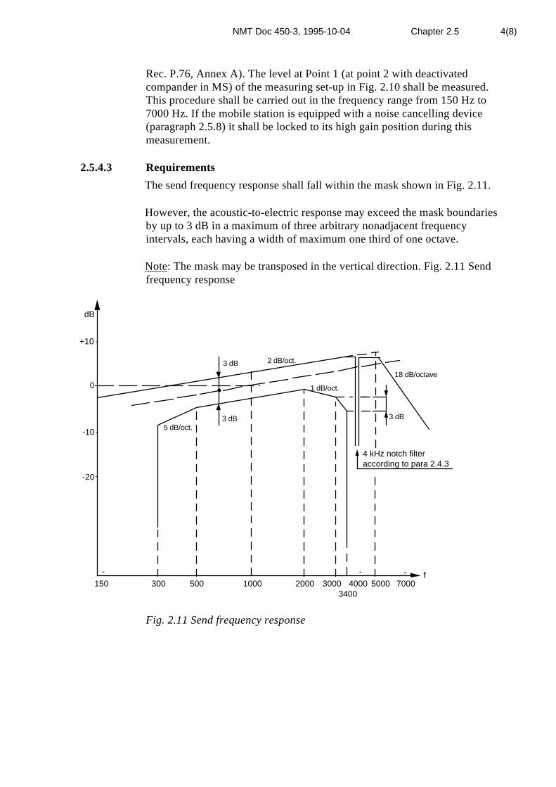
NMT Doc 450-3, 1995-10-04 Chapter 2.5 4(8)
Rec. P.76, Annex A). The level at Point 1 (at point 2 with deactivatedcompander in MS) of the measuring set-up in Fig. 2.10 shall be measured.This procedure shall be carried out in the frequency range from 150 Hz to7000 Hz. If the mobile station is equipped with a noise cancelling device(paragraph 2.5.8) it shall be locked to its high gain position during thismeasurement.
2.5.4.3 Requirements
The send frequency response shall fall within the mask shown in Fig. 2.11.
However, the acoustic-to-electric response may exceed the mask boundariesby up to 3 dB in a maximum of three arbitrary nonadjacent frequencyintervals, each having a width of maximum one third of one octave.
Note: The mask may be transposed in the vertical direction. Fig. 2.11 Sendfrequency response
-
- - -
-
-
dB
+10
0
-10
-20
3 dB 2 dB/oct.
1 dB/oct.
18 dB/octave
4 kHz notch filteraccording to para 2.4.3
150 300 500 1000 2000 3000 4000 5000 7000f
3400
3 dB 3 dB5 dB/oct.
•
Fig. 2.11 Send frequency response
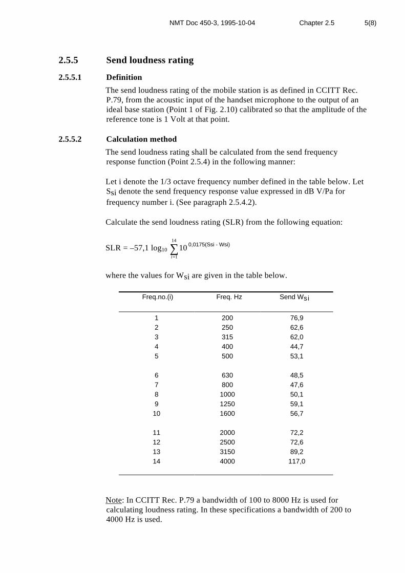
NMT Doc 450-3, 1995-10-04 Chapter 2.5 5(8)
2.5.5 Send loudness rating
2.5.5.1 Definition
The send loudness rating of the mobile station is as defined in CCITT Rec.P.79, from the acoustic input of the handset microphone to the output of anideal base station (Point 1 of Fig. 2.10) calibrated so that the amplitude of thereference tone is 1 Volt at that point.
2.5.5.2 Calculation method
The send loudness rating shall be calculated from the send frequencyresponse function (Point 2.5.4) in the following manner:
Let i denote the 1/3 octave frequency number defined in the table below. LetSsi denote the send frequency response value expressed in dB V/Pa forfrequency number i. (See paragraph 2.5.4.2).
Calculate the send loudness rating (SLR) from the following equation:
SLR = –57,1 log10 101
14
i=∑ 0,0175(Ssi - Wsi)
where the values for Wsi are given in the table below.
Freq.no.(i) Freq. Hz Send Wsi
1 200 76,92 250 62,63 315 62,04 400 44,75 500 53,1
6 630 48,57 800 47,68 1000 50,19 1250 59,1
10 1600 56,7
11 2000 72,212 2500 72,613 3150 89,214 4000 117,0
Note: In CCITT Rec. P.79 a bandwidth of 100 to 8000 Hz is used forcalculating loudness rating. In these specifications a bandwidth of 200 to4000 Hz is used.

NMT Doc 450-3, 1995-10-04 Chapter 2.5 6(8)
2.5.5.3 Requirements
The send loudness rating SLR shall be 3,0 dB ± 2 dB. With deactivatedcompander SLR shall be 0 dB ± 3 dB.
2.5.6 Transmit distortion
2.5.6.1 Definition
The transmit harmonic distortion is defined as the ratio, expressed as apercentage, of the r.m.s. voltage of all the harmonic components of thefundamental audio frequency to the total r.m.s. voltage of the signal afterlinear demodulation and de-emphasis.
2.5.6.2 Method of measurement
An acoustic test tone with a frequency of 1000 Hz shall be applied to thehandset microphone. Its sound pressure level shall be adjusted so that a peakfrequency deviation of the RF-carrier of ±3,5 kHz is obtained. The harmonicdistortion at Point 1 of the measuring set-up in Fig. 2.10 shall be measured.This procedure shall be repeated for a test tone with a frequency of 500 Hzmodulated to a peak frequency deviation of ±3 kHz, and for a test tone with afrequency of 300 Hz modulated to a peak frequency deviation of ± 1,5 kHz.
Note: The maximum undistorted acoustic pressure level provided by anartificial voice may be insufficient for this measurement. If so, a loudspeakermay be used.
2.5.6.3 Requirements
The harmonic distortion shall be less than 5 %.
2.5.7* Transmission idle noise
2.5.7.1 Definition
The transmission idle noise is the psophometrically weighted noise r.m.s.amplitude in dBV at the output of an ideal base station calibrated so that ther.m.s. amplitude of the reference tone is 1 Volt.
2.5.7.2 Method of measurement
The measuring set-up in Fig. 2.10 shall be calibrated so that the r.m.s.voltage of the reference tone is 1 Volt at Point 1. The psophometricallyweighted idle noise r.m.s. amplitude at Point 1 of the measuring set-up shallbe measured.

NMT Doc 450-3, 1995-10-04 Chapter 2.5 7(8)
Note: In order to avoid interference from ambient noise, it may be necessaryto enclose the handset in an acoustically insulated enclosure.
2.5.7.3 Requirements
The psophometrically weighted idle noise r.m.s. amplitude shall not exceed -60 dBV.
2.5.8 Noise cancelling device
This clause applies only to mobile stations equipped with a noise cancellingdevice having a high gain state for higher sound pressure levels (speech) anda low gain state for lower sound pressure levels (noise in the absence ofspeech).
2.5.8.1 Definition
The input/output characteristic is the amplitude of the signal at the output ofan ideal base station as a function of the acoustic sound pressure levelapplied to the microphone.
2.5.8.2 Method of measurement
An acoustic test tone with a frequency of 1000 Hz shall be applied to themicrophone. Its level shall be adjusted so that a peak frequency deviation ofthe RF-carrier of ±3 kHz is obtained. The ratio D0 between the outputamplitude at Point 1 of the measuring set-up in Fig. 2.10 and the amplitudeof the input signal to the artificial mouth shall be measured. The soundpressure level shall subsequently be varied as follows:
range 1 from 40 dB below the initial level to 20 dB below the initiallevel.
range 2 from 20 dB below the initial level to 3 dB above the initiallevel.
The ratio D, defined in the same manner as D0 above, shall be recorded as afunction of input level.
2.5.8.3 Requirements
The difference D - D0 within range 1 shall fall between +1,0 dB and -15,0dB.
The difference D - D0 within range 2 shall fall between +1,0 dB and -1,0 dB.

NMT Doc 450-3, 1995-10-04 Chapter 2.5 8(8)
2.5.9 Separate microphone
The sensitivity of an optional separate microphone shall be determined bythe manufacturer. It is recommended that the sensitivity is set so that themean modulation level, when using the separate microphone according to themanufacturers directions for use, is equal to that obtained when using thehandset. The user shall have no access to any sensitivity adjustment.

NMT Doc 450-3, 1995-10-04 Chapter 2.6 1(7)
2.6 VOICE PROCESSING REQUIREMENTS,RECEIVING
The CCITT Recommendations of the P-series referred to in section 2.6 arethose in CCITT Blue Book, Vol. V, IXth Plenary Assembly, Melbourne, 14-25 November 1988.
For the measurements described in this section, the antenna terminal of themobile station shall be connected, by means of a suitable coupler, to an idealbase station represented by a measuring set-up consisting of three parts (Fig.2.12).
1. The compressor part of a 2:1 syllabic compander with a nominalattack time of 3,0 msec and a nominal recovery time of 13,5 msec.The compander shall meet the requirements in CCITT Rec. G.162.However, the compander parameters shall be calibrated to anaccuracy in line with laboratory instruments.
2. A 6 dB/octave pre-emphasis network.
3. A linear modulator/radio frequency signal generator providing afrequency modulated radio frequency signal with a peak frequencydeviation proportional to its input amplitude. The RF-level at theantenna input terminal of the mobile station shall be 60 dB (µV) E.M.F.
Note: The compressor stage of the ideal base station used for type approvalby the Nordic Administrations will be based on the circuit NE 570.
In this section the term "reference tone" shall mean a tone, transmittedthrough the system, with a frequency of 1000 Hz and producing a peakfrequency deviation of ±3 kHz. The term "reference level" shall, at anypoint, mean the level of the test tone at that point.
MS
21compressor pre-emph. TX lin-mod. coupler
Fig. 2.12 Measuring set-up, receiving
When measuring the mobile station with deactivated compander, thecompressor circuit in point 1 above is bypassed.
The paragraphs below that do not apply when the compander is deactivated,are marked with (*).

NMT Doc 450-3, 1995-10-04 Chapter 2.6 2(7)
2.6.1* Expansion linearity
2.6.1.1 Definition
The expansion linearity is the deviation from the linear relation between theinput amplitude of an ideal base station and the output amplitude of theexpander of the mobile station.
2.6.1.2 Method of measurement
A test signal with a frequency of 1000 Hz shall be applied to point 1 of themeasuring set-up in Fig. 2.12. Its amplitude shall be adjusted to the referencelevel. The ratio Do in dB between the amplitude of the input test signal andthe amplitude of the signal at the output of the expander stage of the mobilestation shall be measured. The input level shall subsequently be varied from+3 dB to -50 dB relative to its initial value. The ratio D between the inputamplitude and the output amplitude shall be recorded as a function of inputamplitude.
Note: The expansion ratio of the expander of the mobile station is 1:2. Thisexpansion ratio is compensated by the compression ratio of 2:1 of thecompressor of the measuring set-up.
2.6.1.3 Requirements
The maximum difference between D and D0 shall be ±1,0 dB.
2.6.2* Transient response of the expander
2.6.2.1 Definition
The definition of transient response shall be as in CCITT Rec. G.162, clause7.
2.6.2.2. Method of measurement
The transient response of the expander shall be measured with a 12 dB stepof a test tone of 2000 Hz applied to Point 1 of the measuring set-up in Fig.2.12. The high and low level of the signal shall be respectively -22 dB and -34 dB relative to the reference level.
The envelope of the signal at the output of the expander stage of the mobilestation shall be recorded for an upward step.
The procedure shall be repeated for a downward step.
Note: The high and low level recommended in CCITT Rec. G.162, clause 7are respectively -4 dB and -16 dB relative to the reference level. The valuesin this specification are chosen in order to avoid possible peak limiting inthe radio path.

NMT Doc 450-3, 1995-10-04 Chapter 2.6 3(7)
2.6.2.3 Requirements
The overshoot (positive or negative) shall in both of the above cases be lessthan 20 % of the final value.
2.6.3 Receive frequency response
2.6.3.1 Definition
The receive frequency response is the ratio in dB, as a function of test tonefrequency, between the nominal sound pressure of the earpiece and thevoltage of the test tone at the input to an ideal base station. By nominalsound pressure of the earpiece shall be meant the sound pressure in anacoustic coupler when the earpiece is placed on the coupler.
2.6.3.2 Method of measurement
The measuring set-up shown in Fig. 2.12 shall be calibrated so that the r.m.s.voltage of the reference tone is 1 Volt at Point 1 (at point 2 with deactivatedcompander in MS). The receive volume control of the mobile station shall bein its nominal position. The handset earpiece shall be placed tightly on anacoustic coupler complying with CCITT Rec. P.51, Section 1, Type 1. A testtone with an r.m.s. voltage of 0,1 Volt ( 0.3 V with deactivated compander inMS) shall be applied to Point 1 of the measuring set-up. The sound pressurelevel in the acoustic coupler shall be measured as a function of test tonefrequency in the frequency range from 150 Hz to 7000 Hz.
Note: The procedure above may be performed as a sweep frequencymeasurement.
2.6.3.3 Requirements
The receive frequency response shall fall within the mask shown in Fig. 2.13.
However, the acoustic-to-electric response may exceed the mask boundariesby up to 3 dB in maximum of three arbitrary nonadjacent frequencyintervals, each having a width of maximum one third of one octave.

NMT Doc 450-3, 1995-10-04 Chapter 2.6 4(7)
Note: The mask may be transposed in the vertical direction.
-
--
-
-
dB
+10
+3
0-3
-10
-20
150 300 500 1000 2000 30003400
4000 7000f
3 dB/octave 24 dB/octave
4 kHz notch filterbandwidth ±55 Hz
3 dB/octave
Fig. 2.13 Receive frequency response
2.6.4 Receive loudness rating
2.6.4.1 Definition
The receive loudness rating is as defined in CCITT Rec. P.79, from theelectric input of an ideal base station to the acoustic output of the handsetearpiece, when the base station is calibrated so that the reference level at theinput to the ideal base station is 1 Volt.
2.6.4.2 Calculation method
The receive loudness rating shall be calculated from the receive frequencyresponse function (Point 2.6.3) in the following manner: Let i denote the 1/3octave frequency number defined in the table below. Let Sri denote thereceive frequency response value in dB Pa/V for frequency number i. (Seeparagraph 2.6.3.2).

NMT Doc 450-3, 1995-10-04 Chapter 2.6 5(7)
Calculate the receive loudness rating (RLR) from the following equation:
RLR = –57,1 log10 101
14
i=∑ 0,0175(Sri - Wri)
where the values for Wri are given in the table below.
Freq. no. (i) Freq. Hz Receive Wri
1 200 93,42 250 79,63 315 80,04 400 63,05 500 71,3
6 630 66,57 800 64,88 1000 66,49 1250 73,9
10 1600 70,3
11 2000 85,012 2500 83,913 3150 100,014 4000 122,6
Note: In CCITT Rec. P.79 a bandwidth of 100 to 8000 Hz is used forcalculation loudness rating. In these specifications a bandwidth of
200 to 4000 Hz is used.
2.6.4.3 Requirements
The receive loudness rating RLR shall be 9,0 dB ±2 dB whether thecompander in MS is active or not.
2.6.5 Receive volume control
The mobile station shall be equipped with a manual volume control,accessible to the user. In its maximum setting the increase in sensitivityrelative to nominal shall be between 8 dB and 20 dB. In its minimum settingthe decrease in sensitivity relative to nominal shall not be more than 12 dB.
If the volume control is of the electronic type, it is recommended that it isreset automatically to its nominal position at the termination of a call.

NMT Doc 450-3, 1995-10-04 Chapter 2.6 6(7)
2.6.6 Receive harmonic distortion
2.6.6.1 Definition
The receive harmonic distortion is defined as the ratio, expressed as apercentage, of the r.m.s. amplitude of all the harmonic components of thefundamental audio frequency to the total r.m.s. amplitude of the acousticsignal of the handset earpiece.
2.6.6.2 Method of measurement
The handset earpiece shall be placed tightly on an acoustic couplercomplying with CCITT Rec. P.51, Section 1, Type 1. The RF-carrier shall bemodulated with a 1000 Hz tone to a peak frequency deviation of ±3,5 kHz.The manual volume control shall be set to a position so that a sound pressureof minimum 10 dBPa is obtained, or to its maximum position. The harmonicdistortion of the acoustic signal in the coupler shall be measured. Withoutreducing the setting of the volume control, the harmonic distortion shallsubsequently be measured for an RF-carrier modulated with a tone of 500 Hzto a peak frequency deviation of ±3 kHz, and for an RF-carrier modulatedwith a tone of 300 Hz to a peak frequency deviation of ±1,5 kHz.
2.6.6.3 Requirements
The harmonic distortion shall not exceed 5 %.
2.6.7* Receive idle noise
2.6.7.1 Definition
The receive idle noise is the nominal A-weighted sound pressure of thehandset earpiece when the mobile station is connected to an ideal basestation emitting an unmodulated RF-carrier.
2.6.7.2 Method of measurement
The mobile station shall be connected to the measuring set up in Fig. 2.12.The RF-carrier shall be unmodulated. The handset earpiece shall be placedtightly on an acoustic coupler complying with CCITT Rec. P.51, Section 1,Type 1. The volume control of the handset shall be in its nominal position.The A-weighted (IEC Standard 651) sound pressure level in the acousticcoupler shall be measured.
2.6.7.3 Requirements
The A-weighted sound pressure level shall not exceed -55 dBPa.

NMT Doc 450-3, 1995-10-04 Chapter 2.6 7(7)
2.6.8 Maximum sound level of handset earpiece
To protect the user from ear damage, the maximum sound level from thehandset earpiece, measured in an acoustic coupler complying with CCITTRec. P.51, Section 1, Type 1, shall not exceed 26 dBPa r.m.s. Thisrequirement shall be valid for any operating condition, any setting ofcontrols, and any combination of modulating frequencies and modulationindexes.
2.6.9 Volume control in "Hands-Free" mode
If a loudspeaker for "Hands-Free" operation or monitoring purposes isprovided, a volume control should be provided. With the mobile station inthe "Hands-Free" mode, it shall not be possible to close the receiver audiopath, i.e. the minimum setting of the volume control shall still permit theuser to notice when speech (of a normal level) is present.

NMT Doc 450-3, 1995-10-04 Chapter 2.7 1(1)
2.7 STABILITY LOSS
2.7.1 Definition
The stability loss is the ratio between the landside input voltage and thelandside output voltage of an ideal base station when the mobile station is inconversation mode (duplex operation).
2.7.2 Method of measurement
The antenna terminal of the mobile station shall be connected, by using asuitable duplexer device, simultaneously to the modulation analyser in Fig.2.10, and to the RF signal generator in Fig. 2.12. The RF-level produced bythe RF signal generator shall be subsequently 30, 60, and 100 dB (µV)E.M.F. at the antenna terminal of the mobile station.
In transmission the measuring set-up shall be calibrated so that an RF-signalmodulated with a tone of 1000 Hz to peak frequency deviation of ±3 kHzshall produce a voltage of 1 Volt at Point 1 of the measuring set-up inFig. 2.10. In receiving the measuring set-up shall be calibrated so that a toneof 1000 Hz with an amplitude of 1 Volt at Point 1 of Fig 2.12 shall producean RF-deviation of ±3 kHz.
The handset volume control of the mobile station shall be set to its maximumposition. The handset shall be placed at the centre of a flat hard-surfacedtable with minimum dimensions 800 x 800 mm. A tone of 0,1 Volt shall beapplied to Point 1 of Fig. 2.12 and the voltage at Point 1 of Fig. 2.10, shall bemeasured. The frequency of the tone shall be varied from 200 Hz to 3400Hz. The stability loss expressed as the ratio in dB between the input voltageand the output voltage shall be recorded.
This procedure shall be repeated for all mechanically stable positions of thehandset, and for all RF-levels mentioned above.
2.7.3 Requirements
The stability loss shall be less than 15,0 dB for any combination offrequency, RF-level or position of the handset.

NMT Doc 450-3, 1995-10-04 Chapter 3 1(11)
3 OPERATIONAL CONTROLS UNIT (OCU)
The Operational Controls Unit is the interface between the user and theNMT-system. This functional unit includes a handset, "Hands-Free"facilities, mobile station controls, indicators, push-button set, dialled digitsdisplay, and tone signals with which the user interacts.
3.1 MOBILE TELEPHONE IDENTIFICATION NUMBER
The mobile station is identified by a telephone number composed ofmaximum 15 digits according to CCITT's number plan E164. The last 6digits are in the following defined as A1...A6.
On the radio path, the mobile station is completely defined by the subscriberidentity ZX1...X6 and K1K2K3 , where Z is used to designate the country,X1...X6 is an identification of the mobile station within the country andK1K2K3 is used in certain signalling sequences as a password .
Programming of the radio path identification ZX1...X6K1K2K3 into amobile station shall only be possible with the special programming toolsdesigned by the manufacturer. The programming procedures shall only beknown to people authorized to operate the programming tools, see alsoAnnex 19.
The telephone number shall be seen as dynamic and can at any time bechanged by the network operator. The composition of the number is subjectto national (local) variations, but normally the A1...A6 of the telephonenumber is equal to the X1...X6 of the radio path identification. In somespecial applications there is no relation between the telephone number andthe radio path identification.
The mobile station shall be provided with a facility which shows theassigned telephone number (up to 15 digits).The shown number shall be easyto change.
It shall also be possible, without special programming tools, to read out theprogrammed Z and X1...X6 of the radio path identification.
Note: K1 = 9 identifies an NMT 450 MS incorporating NMT SIS.

NMT Doc 450-3, 1995-10-04 Chapter 3 2(11)
3.1.1 Secret authentication key
To protect against illicit use of a mobile telephone identification number, anauthentication procedure takes place on all mobile originated calls. Duringthis procedure, a Secret Authentication Key (SAK), a number of thirty hexdigits, is used.
Since the security of the MS identity number only depends on the secrecy ofthe SAK, some strict requirements on the storage of the SAK must befulfilled:
- It shall be impossible to read out the SAK after programming it once.Therefore, the authentication algorithm and the SAK shall be implementedon one chip, the security module, where a SIS-related calculations shall takeplace. This module shall accept RAND as an input signal, and calculateSRES and B-key based on the implemented SAK.
- The SAK shall be programmed either at the MS manufacturers premisesor the security module manufacturers premises during the productionprocess.
- The security module shall be supplied by the manufacturer as a part of theMS purchase process.
- If the security module is designed to be removable, it shall be impossibleto store the mobile subscriber number on a non-volatile memory part of thesecurity module.
- Each security module shall be identified by a unique and non-SAK relatedserial number. It shall be possible to read out the serial number of the actualsecurity module in use in a simple way, e.g. via the MS display.
- One common test SAK shall be available in all security modules.Selection of a MS test mode to select this test SAK shall, for servicepurposes, be possible. The value of the test SAK shall be set to:
TESTSAK = (K1/K2/K3/K4/K5/K6),with K1 = 215 + 1= (8001)hex
K2 = 231 + 1= (80000001)hexK3 = 247 + 1= (800000000001)hexK4 = K5 = K6 = 0 = (0)hex
- After power-off the MS shall return to using the original SAK, i.e. the testSAK (testmode) have to be selected after each individual power-on.
NMT Doc 450-3, 1995-10-04 Chapter 3 3(11)
3.1.1.1 The generation and programming of SAKs
The manufacturers shall generate the SAK using a random generator (seeannex 16). The total length of the SAK is 120 bits. The SAKs areprogrammed in MSs.
3.1.1.1.1 General requirements
1. Generating and programming SAKs shall only be possible with specialprogramming tools designed by the manufacturers and approved by theadministrations. The programming procedures shall only be known to peopleauthorized to operate the programming tools.
2. Generating SAKs, programming SAKs and enciphering SAKs shall bedone in a consecutive order without unnecessary delay.
3.1.1.1.2 Generation of the SAK
The SAK is divided into six parts
SAK = (K1/K2/K3/K4/K5/K6).
The following requirements shall be fulfilled.
1. The length of K1 is 16 bits.2. The length of K2 is 32 bits.3. The length of K3 is 48 bits.4. The length of K4, K5 and K6 is 8 bits each.5. The first bit i.e. the most significant bit of K1, K2 and K3 is set to 1.6. The SAK should be generated by a random generator according to
annex 16.7. K1 should contain at least 2 zeros and at least 2 ones.8. K2 should contain at least 4 zeros and at least 4 ones.9. K3 should contain at least 6 zeros and at least 6 ones.10. The value of K3 should not be divisible by any prime less then 5000.
3.2 "ON/OFF" SWITCH (OPTION)
An "ON/OFF" switch shall be provided to switch the power "on" or "off".

NMT Doc 450-3, 1995-10-04 Chapter 3 4(11)
3.3 HANDSET
MANDATORY:
If a handset is provided, all relevant acoustical requirements shall apply.
OPTION:
A handset is optional.
3.4 "HANDS-FREE" OPERATION (OPTION)
Operation of the mobile station in "Handset" mode as well as in "Hands-Free" mode shall be possible. For this purpose the mobile equipment shallpermit simultaneous connection of the handset as well as a fixed mountedmicrophone with an associated loudspeaker.
A separate "Push-to-talk" button for manual speech-path switching isoptional.
A mobile station may be equipped with a loudspeaker just for monitoring thesignal path MTX-MS (listening) in "Hands-Free" mode.
The handset earpiece may be used as a monitoring loudspeaker
a) when the handset is mechanically cradled and
b) the monitoring volume is automatically reduced to normal volume whenthe handset is uncradled.
If a loudspeaker is not connected, the MS shall not be able to enter "Hands-Free" mode.
3.5 Deleted
3.6 DIALLING FACILITIES
3.6.1 Push-button set (OPTION)
A 12-button set shall be provided:
- 10 digit buttons (1,2,3,4,5,6,7,8,9 and 0)
- and buttons for * and #
The push-button set shall be available for use in "on-hook" condition as wellas during conversation.

NMT Doc 450-3, 1995-10-04 Chapter 3 5(11)
3.6.2 Dialled digits memory (DDM)
MANDATORY:
The MS shall be able to store at least 23 digits in the DDM.
OPTION:
A dialled digits display shall be provided (see paragraph 3.9.5).
If the number of digits selected by the push button set exceeds the storagecapacity of the dialled digits memory, the last selected digits shall be storedin the memory (first in-first out).
The DDM and dialled digits display shall be cleared when:
- the user has applied a "cancellation procedure"
- the MS goes "on hook"
- the content has been sent to MTX or address complete is received fromMTX
In the conversation state digits selected on the push-button set may be storedin the DDM (and display). The information shall be stored in abbreviatednumber store position 00 and the DDM (and display) cleared when theconversation is terminated.
The information is retrieved (recalled into DDM and displayed) by selecting
the abbreviated number 00 #.

NMT Doc 450-3, 1995-10-04 Chapter 3 6(11)
3.7 ACOUSTIC SIGNALS GENERATED BY THEMOBILE STATION (OPTION)
3.7.1 General
At least two types of acoustical alarms shall be provided as described below.However they may be suppressed by means of user action. All otheracoustical signals shall be distinguished audibly from these.
3.7.2 Ringing signal
An acoustic ringing signal having a duration of approximately 1 sec shall beprovided to inform the user of an incoming call (MTX-MS). The sound levelmay be adjustable.
The ringing signal shall be generated locally in the mobile station and beactivated when receiving frame 5a (L=9) in signalling scheme MTX-MS.
3.7.3 Malfunction alarm
The malfunction alarm shall be clearly distinguished from the ringing signal.
The malfunction alarm shall be activated due to:
a) - unsuccessful call attempt
b) - MTX forced release or clearing.
c) - the user initiating "off-hook" when the MS is in signalling scheme D(roaming information), according to the state tables, see paragraph 5.3.
As an option the malfunction alarm may, in the following special cases inîpower on" condition, be activated when the mobile station is "on hook" toalert the user:
d) - When the roaming alarm is activated.
e) - When the voltage supplied to the mobile station drops below a certainvalue.
f) - In conversation state, a short period before the MS turns off due to lowbattery voltage.

NMT Doc 450-3, 1995-10-04 Chapter 3 7(11)
3.8 COUNTRY SELECTOR
MANDATORY:
Automatic country selection is not allowed. The assigned Y1-values aremandatory for the countries that are included in a country selector.
"FI or FINLAND" is mandatory as indicators for FINLAND(From 1/1 1994) as soon as a country indicator is implemented.
OPTION:
A country selector, which determines a group of traffic areas (correspondingto the mobile telephone network of one country) where the mobile stationcommunicates, shall be provided. The traffic area groups are characterizedby Y1 in the traffic area number Y1Y2. A mobile station without countryselector can not roam to another country.
Y1 are reserved for assignment to countries. The same value of Y1 can beassigned to more than one country. The mobile subscriber selects countrymanually when travelling from one country to another.
The number of country indications shall be at least eight. The selectedcountry shall be indicated to the user by letters in a clearly visible way. Incase the selected country is indicated on the dialled digits display, (DDD, seeparagraph 3.9.5), the country indication shall be shown unless specifiedinformation regarding dialled digits memory, register recall function andMFT function is shown on DDD.
The information about the selected country shall be memorized for at leastone week when the MS is in "power off" condition. See also paragraph5.2.1.1
The Y1 assignments to the countries below are shown in the following table.

NMT Doc 450-3, 1995-10-04 Chapter 3 8(11)
Table of used Y1 values
Country / Region Operator assigned Value of Y1 Recommended indication /(ISO)
Denmark Tele Danmark Mobile 5 DKSweden Telia Mobitel 6 S or SENorway Telenor Mobil 7 N or NOFinland Telecom Finland 8 FIIceland
Faroe IslandsEstonia
Post & TelecomFaroese TelecomEesti Mobiiltelfon
857
ISFOEE
Latvia Latvian Mobile Telephone 5 LVLithuaniaBelarus
OSS/MoscowOSS/St Petersburg
OSS/Leningrads Dist.OSS/Carelian Rep.
OSS/Murmansk
COMLIETBelcel
Moscow Cellular Comm.Delta TelecomDelta Telecom
Telecom FinlandTelecom Finland
8656675
LTBYMOSTPSTPCARMUR
OSS/Leningrads Dist. Telecom Finland 5 LEDKaliningrad Telecom Finland 5 KAL
Poland CENTERTEL 7 PLBulgaria MOBIFON 6 BGRomania Telefonica Romania 5 ROUkraine Ukraine Mobile Comm. 8 UA
1 RU12 RU23 RU34 RU4
The indication to the user is a recommendation except "FI or Finland".
The table is under constant revision. The latest version can be retrieved fromthe operators.
Y1=0000 is recommended for systems with no roaming with the existing 450countries.

NMT Doc 450-3, 1995-10-04 Chapter 3 9(11)
3.9 VISUAL INDICATORS
General
The selection of colour and/or position of other indications to the usershall be such that the mandatory indicators can be clearly distinguishedfrom the Dialled Digits Display and optional indicators.
It shall be possible to display the status of all mandatory indicatorssimultaneously.
The state "power on" shall be visually indicated to the user
3.9.2 Service indicator
The service indicator shall be shown to the user as long as the MS is lockedto a calling channel. If the indication is coloured it shall be green.
Recommended symbol is (circle).
3.9.3 Call received indicator (OPTION)
The call received indicator shall be flashing periodically whenactivated. It shall be constantly shown to the user, starting when theMS is in the state "wait for next ringing order" until the user invokesoff-hook .
Recommended symbol is (square).
3.9.4 Roaming alarm indicator
The roaming alarm indicator shall be shown to the user as long as the MS isin roaming alarm state i.e. the automatic updating procedure has failed. Ifthe indication is coloured it shall be red.
Recommended symbol is
(triangle).
3.9.5 Dialled digits display (DDD) (OPTION)
A dialled digits display shall be provided. The number of displayed digitsshall be minimum 8.The display shall be able to show the decimal digits 0-9,
* and #.

NMT Doc 450-3, 1995-10-04 Chapter 3 10(11)
The content of the display shall be in accordance with the content ofthe dialled digits memory (except in the state dialled digits memoryempty). If the display has fewer positions than the dialled digitsmemory, the least significant part (last selected digits) shall be shownon the display. Furthermore, when the dialled digits memory is in theempty state, and the dialled digits display is not used for register recallfunction (see Annex 8) or MFT function (see Annex 6), the dialleddigits display may be used for showing other information to the user,e.g. about MS facilities. This other information shall not be transferredto the dialled digits memory.
3.9.6 Off hook indicator
The "off hook indicator" informs the user that the MS is in off hookstate. The indication shall be clearly distinguished from otherindicators.
3.9.7 Selected country indicator (OPTION)
See paragraph 3.8
The country indicator shall be visible after power on. It may be suppressedby user action.
3.10 SUPPLEMENTARY FACILITIES (OPTION)
3.10.1 Shift Mode
1. The functions of the push-button set in paragraph 3.6.1 may be temporarilychanged by one or several "shift-modes"
The "shift modes" shall not change the meaning of the On-Hook/Off-Hookoperations or the power on/off functions.
2. The meaning of the push button set shall revert to normal 10s after the lastbutton pushed. If the selected shift function by its nature requires more than10s, e.g. voice-mail retrieval, the 10s timer shall start after the termination ofthe function.
3. Any function invoked by "shift mode" and subsequent keyoperation, may remain active after the 10s period providing they do notinterfere with any mandatory function.

NMT Doc 450-3, 1995-10-04 Chapter 3 11(11)
3.10.2 Immediate call transfer indication
The MS may have an indicator or indication to show that an immediate CallTransfer service is activated in the MTX. Recommended symbol is ->(arrow).
The indicator is controlled by the clearing signal received from the MTX.See NMT Doc 450-1.
3.10.3 Transmission of MFT signalling from MS
Transmission of MFT signalling may be possible via the push button set inthe MS. In this case, the 1200 baud FFSK signalling from MS is converted toMFT signalling by means of an MFT converter in the MTX. (See Annex 6.)
3.10.4 Locking facility requirements
The MS may be equipped with a mechanical or electronic locking facility toprevent undesired use. However, when the MS is in Power On state,emergency calls to the international emergency number 112 and nationalemergency numbers must be possible.

NMT Doc 450-3, 1995-10-04 Chapter 4 1(7)
4 OPERATIONAL PROCEDURES
The operational procedures concerning initiation and termination of callscan be done in different ways, depending on the facilities of the MS. Thespecifications for the different types are listed below.
4.1 GENERAL REQUIREMENTS
MANDATORY:
A: The user shall always have a one-step access to the on-hook function.
OPTION:
B: The user shall always have a one-key access to the off-hook function
C: Going into and out of Hands-Free mode shall be possible from either OnHook state or Off-Hook state.
Some additional procedures are described in the following paragraphs.
4.2 MANUAL ROAMING UPDATING
4.2.1 Updating by initiating "off-hook"
State: Power "on", "on-hook", roaming alarm, DDM empty.
User action MS-response
Initiate "off-hook" Service indicator "off" (if activated). Off hookindicator "on". Roaming alarm turned "off" (when roaming updatingconfirmation is received from MTX)
Malfunction alarm (may be delayed maximum 5 seconds)
Initiate "on-hook" MS back to standby. off hook indicator "off"

NMT Doc 450-3, 1995-10-04 Chapter 4 2(7)
4.2.2 Updating by generating a call
State: Power "on", "on-hook", roaming alarm, digits in DDM.
User action MS response
Initiate "off-hook" togenerate acall
(Conversation)
Service indicator "off" (if activated). Offhook indicator "on". Roaming alarmturned "off" (when roaming updatingconfirmation/proceed to send is receivedfrom MTX)

NMT Doc 450-3, 1995-10-04 Chapter 4 3(7)
4.3 ABBREVIATED DIALLING (OPTION)
The MS shall have an abbreviated number store with a minimum storagecapacity of fifty 23-digit telephone numbers.
The push-button set in the MS shall be used for programming, cancellation,and check of the content of the abbreviated number store. The followingprocedures shall be used:
State: power "on", "on-hook" or conversation state
User action MS-response
Programming
Dial *X1X2*S1...Sn# Digits stored in dialled digits memory
* The telephone number S1S2...Sn is storedin the abbreviated number store. Dialleddigits memory is cleared.
Cancellation
Dial #X1X2# Digits stored in dialled digits memory
* Cancellation of this abbreviated numberis done in the abbreviated number store.Dialled digits memory is cleared.
Check
Dial X1X2 Digits X1X2 are shown on the display
# The corresponding telephone number isshown on the display. The last digits aredisplayed if the telephone number islonger than the display capacity.
# or ## The display is cleared

NMT Doc 450-3, 1995-10-04 Chapter 4 4(7)
Activation of the abbreviated number store
Dial the abbreviatednumberX1X2
Digits X1X2 are stored in dialled digitsmemory.
# The actual telephone numbercorresponding to the abbreviated numberis stored in dialled digits memory.
Initiate "Off-Hook" Service indicator "off". Off hookindicator "on". MS searches for a freetraffic channel. When found, digits aretransmitted to MTX.
(Answer)
(Conversation)
Note: X1X2 ( or X1 only ) is the abbreviated number, and S1S2....Sn is thecorresponding telephone number.
The digit S shall accept the values 0-9, *, and #. The code #* indicates
that a programming/cancellation in the abbreviated number store shall bedone.
Cancellation of wrong dialled information shall be done by dialling ##.
In case the last digit Sn is # when programming the abbreviated number
store, the last digit (Sn = #) shall not be considered as part of the
cancellation procedure ##.

NMT Doc 450-3, 1995-10-04 Chapter 4 5(7)
4.4 DIALLED DIGITS MEMORY (DDM) (OPTION)
The dialled digits memory shall store the digits dialled by the user in "on-hook" condition or in conversation state. This includes also * and #.
The memory and dialled digits display shall be cleared when:
- the user has applied a "cancellation procedure" (##) during dialling
- MS goes "on hook"
- all the digits have been sent to the MTX or address complete is receivedfrom MTX
In case the dialled digits are *X1X2*S1S2...Sn and X1X2 is equal to a valid
abbreviated number, and Sn is #, the last digit (Sn=#) shall not be
considered as a part of the cancellation procedure ##.
Recall of the last dialled number shall be possible by dialling the abbreviatednumber 0#. A repeated call attempt can then be performed by initiating "offhook".
The content of DDM shall be copied into abbreviated number store position0 when the MS goes "off hook".

NMT Doc 450-3, 1995-10-04 Chapter 4 6(7)
4.5 ADDITIONAL USE Of THE PUSH-BUTTON SET
MANDATORY:
If no display is provided, the NMT SIS reference number shall be easilyreadable from number plate, sticker or similar.
In conversation state
- the push-button set shall be blocked until all digits in DDM have beensent to MTX in the call set-up procedure and until address complete isreceived.
In standby state
- The MS shall be equipped with a possibility for the user to easily read theNMT SIS reference number (18 decimal digits). The NMT-SIS referencenumber is composed as follows:
Manufacturers number (4 digits)Production date (6 digits)Sequence number (5 digits)Checksum (3 digits)
- The presentation to the user shall be in decimal form and in the sequenceindicated above.
OPTION:
- the content of DDM (initiated during conversation) shall be stored in theabbreviated number store position 00 when the call is terminated (on hook)

NMT Doc 450-3, 1995-10-04 Chapter 4 7(7)
1
Call clearedOn-
Hook?
Conversation
noyes
MS on HookDDM empty
Callreceived
?
Call cleared
Start
Off-Hook
?
Timelimits exce-
eded?
yes
yes
yes
no no
no
go to 1
DefinitionMS = Mobile StationDDM = Dialled Digits Memory
Initial states- MS power on- Country selector correct- No roaming alarm
Call cleared
Callreceived
?
Digits
Off-Hook
?
selected?
Timelimits exce-
eded?
MS on HookDDM not empty
OffHook
?
Initiate callMS ⇒ MTX
yes
yes
yes
yes
yes
no
no
no
no
no
go to 1
Note:Hands-Free mode is considered to be inlogical parallel with Off-Hook. Switchingbetween Hands-Free and Off-Hook , andvice versa, shall always be possible.See also paragraph 4.1
Fig 4.1
Operational procedures Flow Chart

NMT Doc 450-3, 1995-10-04 Chapter 5.1 1(2)
5 LOGIC AND CONTROL UNIT (LCU) ANDSIGNALLING EQUIPMENT
5.1 GENERAL
The LCU functions as the master control for the MS states, supervises properfunctioning and decides the appropriate actions to be taken. The main statesare:
- Power off- Standby- Signalling- Search for CC- Search for TC, MS off hook- Search for TC, roaming flag set, MS on hook- Search for TC, no roaming flag set, MS on hook- Conversation
The LCU communicates with and controls the following entities:
- Signalling equipment- OCU (Operational Control Unit)- Transceiver- Audio Processing Circuits (APC)- Power supply system.
Upon Input/Output signals from these entities, the LCU decides appropriateactions to be taken.
Some of the functions of the Logic and Control Unit are:
* Decoding orders from the MTX such as:- alerting the user to an incoming call (ringing order)- channel command- adjusting the transceiver output power- identity and authentication request- releasing the MS at completion of a call or forced release.- calculation in a dedicated security chip of SRES and B-key on basis of thereceived RAND- encryption of the dialled digits based on the calculated B-key
* Receiving general identification signals from the MTX such as:- traffic area identification- calling channel identification- free traffic channel identification

NMT Doc 450-3, 1995-10-04 Chapter 5.1 2(2)
* Evaluating and ordering the necessary steps to be taken by the mobilestation
* Encoding the signalling information to the MTX such as:
- call initiation from MS (identification and authentication )- clearing signal when terminating a call- updating roaming information- dialled digits, encrypted or not, for call origination* Providing subscriber signalling information such as:
- ringing signal- roaming alarm- malfunction alarm- service indicator- call received indicator
Audio Proces-sing CirquitsAPC
Transceiver
Power supply
Logic &Control UnitLCU
Signallingequipment
OperationalControl UnitOCU
Fig. 5.1 Logic connections between the LCU and other entities in the MS
NMT Doc 450-3, 1995-10-04 Chapter 5.2 1(16)
5.2 DESCRIPTION OF LCU ACTIVITIES
This paragraph describes how the LCU functions shall be carried out. Theparagraph consists of:
- Description of main states
- Description of minor states in the signalling state
- Task description
5.2.1 Description of main states
The procedures to be carried out by the LCU depends on:
- In which state the MS is from the outset.
- To which state the MS is ordered by the user, timing circuits or the MTX.
Transferring the MS from one state to another is described in the signallingprocedures in NMT Doc 450-1, the input/output state relations (5.3) and theexplanatory flow diagrams (5.4).
The logic connections between the main states are shown in fig. 5.2.
5.2.1.1 Power off
The MS is in "OFF" state when the "ON/OFF" switch is turned "OFF" or ifthe voltage supplied to the MS falls below V volts (as specified by themanufacturer). In this state, no external power except for support charging ofbackup batteries shall be applied to the MS. In "OFF" condition, thefollowing information shall be stored in the MS:
- the actual setting of the country selector, see paragraph 3.8.- the traffic area number Y1Y2 recorded and stored at the
moment the MS was switched "OFF";- the roaming alarm status information,- preprogrammed addresses (numbers)- SAK and MS identity number- Immediate call transfer status (if implemented)
Also other information e.g. call received indicator state may be stored.This information shall be maintained in the "OFF" condition for at least oneweek without support charging of possible back-up batteries.

NMT Doc 450-3, 1995-10-04 Chapter 5.2 2(16)
Main states for LCUPower off
Search for CC
Conversation state Signalling state
Standby
Signalling state, scheme B
1
2
3
4
5
6
7
Power off
Power on task
Fig. 5.3
Onhook
?
no
Roaming?
CCaccepted
?
no
yes
yes
Store channelnumber and Y Y1 2
Onhook
?
Loss of
ZX1..X6match
Conversation
PowerCommand
?
Forced
ClearingCommand
?
SCIPCommand
?
Option
Power changeScheme C
Forced releaseScheme F
MS clearingScheme E
SCIP fnct.Scheme C
MFT orRegister recallScheme
A
B
B
C
D
no
no
no
no
no
no
no
yes
yes
yesyes
yes
yes
yes
yes
yes
yes
no
no
no
MS off hookSearch for TC
MS on hookSearch for TCRoaming flag set
Call Ackn. &wait for order
Scanfor TC
?
Channelorder
?
Call MTX MSScheme B
Call MTX MSScheme B1
Call MS MTXScheme A
RoamingprocedureScheme D
CC locking?
Search for TCNo roamingflag set
MFT orRegister recall
activated?
releaseCommand
?
1
no
yes
>
>
>
yes
no
Authenticationduringconversation
Authenticationand ID request
C
Fig. 5.2

NMT Doc 450-3, 1995-10-04 Chapter 5.2 3(16)
5.2.1.2 Standby
In this state, the MS rests on a calling channel with valid traffic area numberand calling channel prefix (or combined calling/traffic channel prefix) andthe channel number is the same as in the RF-synthesizer. The MS is readyfor reception or initiation of a call.
In the standby state the MS shall read the additional information as describedin NMT Doc 450-1.
If the MS loses the lock to the calling channel it starts the procedure searchfor calling channel (see paragraph 5.2.1.4.)
If the MS receives its own identity in frame 2a, it leaves the procedurestandby state and enters the signalling scheme B or B1 (see fig 5.2).
If the user initiates a call, the MS leaves the standby state and enters theprocedure search for traffic channel (see paragraph 5.2.1.5.)
When the MS leaves the calling channel, the Logic and Control Unit shallstore this channel number (previous CC).
In the standby state the service indicator is activated.
Loss of locking to a calling channel
The MS shall enter the state search for CC if:
a) The received RF level has been less than 10 dB (µV) E.M.F. ±4 dB during75 % of the last 2 minutes (±20 seconds.)
b) The signalling frame 2a (call to actual MS) has been received twicewithout receiving frame 2b, 2c, 2d or 2f (channel order) during 10 seconds(±1 second) after the first received 2a frame. The MS shall wait for channelorder in 2T before entering the state search for CC. The10 sec. period does not include the waiting time for frame 2b, 2c, 2d or 2f.
c) More than two consecutive frames are lost. See NMT Doc 450-1
After loss of channel locking, the MS shall start searching from a "random"channel.

NMT Doc 450-3, 1995-10-04 Chapter 5.2 4(16)
5.2.1.3 Conversation
The MS reaches the conversation state after completion of signallingschemes A, B, B1 or C. In this state, the speech path is through connected inthe MS and the supervisory signal is looped back to BS. The MS shall besensitive to channel order, power change command, authentication and ID-request and forced release from MTX.
The MS shall not be sensitive to compander in/out orders during theconversation state. The MS shall only be sensitive to these signals during thefollowing periods:
Scheme A: In T (8 frames) after reception of address complete( first received frame 5a (L= 6))
Scheme Band B1: In T (8 frames) after transmission of MS answer (last
sent frame 13a (L=14))
Scheme C: In T (8 frames) after transmission of MS identity ( lastsent frame 10b)
If the user terminates the call and replaces the handset, the MS closes thespeech path and the supervisory signal loop, and enters the signalling stateMS clearing.
If the MS receives clearing signal, the speech path and the supervisory signalloop are closed, and the MS enters the signalling state forced release.
When the MS receives channel order, it enters signalling scheme C. Whenthe MS receives an ID and authentication request it enter signalling scheme,authentication during conversation.
The MS shall stay in the conversation state even after voltage drops to 6 V orlower for a period of at least 3 seconds, but not longer than 12 seconds, towithstand start of the engine or change of battery pack in case of HMS.
During conversation the MS may have an autonomous change of the outputpower. See para. 5.7.1.2.
5.2.1.4 Search for channels
In the states search for CC and TC the MS uses the following information:
- Country selector setting
- Number of complete scans performed
- Received RF level
- Stored Y1Y2

NMT Doc 450-3, 1995-10-04 Chapter 5.2 5(16)
5.2.1.4.1 Definitions
Traffic area number Y1Y2
Y1Y2 are specified in NMT Doc 450-1. Y1 indicate traffic area group(country).
Y2 indicates the actual traffic area.
Stored traffic area number is the number of the traffic area where the MS isupdated.
The initial channel is the channel on which the MS starts scanning.
Random channel means a channel chosen in a random way within the band.
Previous channel is the last CC, CC/TC or TC to which the MS has beenlocked. The MS shall store the power bits and channel number received inthe last frame on this channel.
Scanning is the systematical one-by-one search for an RF channel within thechannel band according to the channel acceptance procedure. The scanningis divided in three parts, A, B and C, during which different RF levelcriterias are used.
RF level A is the part where the MS shall accept a channel with an RF levelabove 24 dB (µV) E.M.F. and it shall reject channels with an RF level below16 dB (µV) E.M.F.
RF level B is the part where the MS shall accept a channel with an RF levelabove 14 dB (µV) E.M.F and it shall reject channels with an RF level below6 dB (µV) E.M.F.
RF level C is the part where the MS shall accept a channel with an RF levelabove 0 dB (µV) E.M.F. +2 dB (µV) E.M.F. at extreme test conditions and itshall reject channels with an RF level below -4 dB (µV) E.M.F. -6 dB (µV)E.M.F. at extreme test conditions.
A scan is one complete search through all the RF channels within the channelband The scanning shall be done in 25 kHz steps.
"On hook" is the state where the MS is internally "on hook" independent ifit is cradled or not. (Cradle switch is optional.)
Test for roaming. This state is entered, when the MS has detected a CC witha new traffic area number Y1Y2'.
Roaming flag set is the state where the MS searches for a free marked trafficchannel in the new traffic area in order to initiate roaming updating (schemeD).
The scan counter counts every scan through the channel band.

NMT Doc 450-3, 1995-10-04 Chapter 5.2 6(16)
5.2.1.4.2 Channel acceptance procedure
This section contains the requirements for accepting a calling channel (CC),a free marked traffic channel (TC), or a combined CC/TC.
The number of scans used for each RF level in the scanning procedure aregiven in table 5.2.1.4.2 below.
Used RF level criteria Number of scans
RF level A 1
RF level B 3
RF level C 11
Table 5.2.1.4.2 Number of scans in the scanning procedure
When the MS detects a carrier, it shall check whether the channel ismodulated with an FFSK signal or not. If no FFSK signal is detected within20 ms the receiver goes to channel N+1. The specified 20 ms includes thechannel switching time.
During the first scan the MS shall not accept combined CC/TC in search forTC.
The total number of scans for A, B and C is set to maximum 15 scans.
During search for a channel the MS shall check that there is a match betweenthe received channel number information and the synthesizer setting afterhaving detected RF and FFSK. Then the Y1Y2 shall be checked. Y1 shallmatch the setting of the country selector (see paragraph 3.8). Y2 shall bechecked for a match with the stored traffic area information.
The MS shall check that the relevant channel prefix is received, see NMTDoc 450-1.
If there is a mismatch in the check, the MS shall switch to next channel. Allthese checks shall be carried out within T''' (two frames) after switching tothe channel.
5.2.1.5 Search for calling channel
This procedure is initiated e.g. after DC power start up or if the MS goes onhook.
Whenever the MS enters this procedure after leaving the signalling scheme(A, B, D and clearing), it shall start the scan on the previous calling channel.
Entering this procedure from any other state (including scheme B1), the MSshall start the scan from a random channel as initial channel. For eachchannel the MS shall execute the channel acceptance procedure. When a

NMT Doc 450-3, 1995-10-04 Chapter 5.2 7(16)
calling channel with a stored traffic area number is found, the MS shall lockto this channel and enter standby state.
The MS shall accept a CC with a new traffic area number Y1Y2 (within thesame traffic area group Y1) if:
a. no acceptable CC with the old traffic area number is detected in twoscans,
and
b. an acceptable CC with a new Y1Y2 is detected twice.
If a new Y1Y2' has been accepted, the MS shall replace the stored Y1Y2 withthe new Y1Y2' and enter the state roaming flag set.
These conditions may be processed simultaneously (i.e. two complete scansmay be sufficient for the decision of roaming updating).
The MS shall then search for a traffic channel in the traffic area Y1Y2' andinitiate signalling scheme D. After completion of signalling scheme D, theMS shall return to the new calling channel. If signalling scheme D is notsuccessfully completed, the MS shall enter the roaming alarm state. Also inthis case the MS shall return to the new calling channel.
If a mobile subscriber initiates a call while the MS is searching for a callingchannel, the MS shall leave this procedure and start searching for a trafficchannel as described in paragraph 5.2.1.6

NMT Doc 450-3, 1995-10-04 Chapter 5.2 8(16)
State: Search for CC
MS goes to randominitial channel withinthe channel band,clear scan counter
MS goes to previousCC (initial channel),clear scan counter
MS goes to nextRF-channel withinthe channel band
Incrementscan counters
Change RFlevel acceptancecriteria
Channel= initialchannel
?
RFlevel accept-ance criteria
ok?
yes
yes
no
no
no
no
no
no
no
no
no
1 2
4Standby(Fig. 5.2)
= stored Y Y1 2
Y Y1 2
AcceptableCC?
Validchannelnumber
?
13
On hook? 6
yes
yes
Carrierdetected
?
yes
Datasignal received
within 20 ms?
5Search for TC,roaming flag set,MS on hook(Fig. 5.5)
yes
yes
yes
yes yes
yes
Search for TCMS Off hook(Fig. 5.4)
scans withoutTwo or more
acceptable oldY Y1 2
New Y Y1 2detected intwo scans
Store channelnumber and Y Y
Fig. 5.3

NMT Doc 450-3, 1995-10-04 Chapter 5.2 9(16)
5.2.1.6 Search for free marked traffic channel(MS off hook)
The search for free marked traffic channel shall start from a channel selectedat random . The purpose of this procedure is to distribute the call attemptsamong all free marked traffic channels.
Scheme A
A necessary condition for entering scheme A is that the MS is "off hook" orthe "Hands-Free" button is activated. There are three (four as an option)possibilities depending on the status information.
- No roaming flag set, no roaming alarm.
This is the normal case for an ordinary call. When the MS has locked to afree marked traffic channel , it enters scheme A.
- No roaming flag set, roaming alarm.
In this case, the MS shall accept any traffic channel which is in accordancewith the country selector. After a successful completion of scheme A the MSis updated and the call is completed. The used traffic area number Y1Y2shall be stored as the updated traffic area.
- Roaming flag set, no roaming alarm.
This is the case where the MS goes "off hook" while searching for a freemarked traffic channel as described for scheme D. When the MS has lockedto a free marked TC it enters scheme A and in addition updates itself.
- No roaming flag set, no roaming alarm, no previous Y1Y2 detected.
As an option MS may also accept a TC on a new traffic area Y1Y2 and enterscheme A, if:
a. No acceptable CC with the old traffic area number Y1Y2 (stored in MS)is detected in two scans and
b. an acceptable CC with a new Y1Y2 is detected twice.
This requires simultaneous processing of search for CC (see paragraph5.2.1.5)and search for TC
This optional function is not specified separately in detail in state tables(paragraph 5.3). Simultaneous processing of search for CC must beperformed as in states 4.5 (without locking to the CC), 4.6 and 4.7.

NMT Doc 450-3, 1995-10-04 Chapter 5.2 10(16)
After acceptance of the new Y1Y2, search for TC on the new Y1Y2 mustbe started from the beginning (as specified in paragraph 5.2.1.4). If searchfor TC on the new Y1Y2 fails before completing state 15.1 (proceed tosend/roaming updating confirmation received), the MS shall activate bothroaming alarm indicator and malfunction alarm and return to search for CC.
If no free marked traffic channel is found during 15 scans, the MS shall go"on hook" and activate malfunction alarm.

NMT Doc 450-3, 1995-10-04 Chapter 5.2 11(16)
State: Search for TC, MS OFF hook6
3
A
Malfunctionalarm
Onhook
?
Free TC?
1Y Y = stored Y Y
21 2
?
Clear "scan-counter"Clear "test for
"Scan-counter"> 15
?
Change RF-levelacceptance criteria
criteria
RF
ok?
Increment"Scan-counter" Valid channel
number?
MS goes to nextRFchannel withinthe channel band
Carrierdetected
?
MS goes to randominitial RF-channelwithin the channel
band.Clear scan-counter
no
no
no
no
no
no
no yesyes
yes
yesyes
yes
Datasignal received
within 20?
channel=initial channel
RF-
?
nono
yes
yes
Search for CC(Fig. 5.3)
Search for CC(Fig. 5.3)
yes
roaming, electricallyon hook"
Call MS-MTX(Fig. 5.7)
3
acceptance
Fig. 5.4

NMT Doc 450-3, 1995-10-04 Chapter 5.2 12(16)
5.2.1.7 Search for TC, roaming flag set, MS on hook
When a new Y1Y2' is accepted, the MS shall replace the stored Y1Y2 withthe new Y1Y2' and enter the state roaming flag set.
The MS shall then search for TC with traffic area number Y1Y2', see fig 5.5.After completion of the signalling scheme D, the MS shall return to the newcalling channel. If the signalling scheme D is not successfully completed, theMS shall enter the roaming alarm state. Also in this case the MS shall returnto the new calling channel.
The search for free marked traffic channel shall start from a randomlyselected channel . Scheme D is initiated only when the MS is "on hook" andin the state roaming flag set, no roaming alarm.
The MS is in a state where it has the information that Y1Y2 has changed toY1Y2'. It shall now search for TC with the traffic area marking Y1Y2' andenter scheme D.
If the MS does not find a free marked traffic channel within 15 scans, itclears the Y1Y2' and enters the search for calling channel procedure.
5.2.1.8 Search for TC, No roaming flag set, MS on hook.
If the MS has sent call acknowledgement in signalling scheme B and thereare no free marked traffic channels associated to the actual CC, the MTXmay order the MS to search for a free marked traffic channel onneighbouring base stations. There the MS will report and ask for the call.
The search for TC shall start from a randomly selected channel.
If no TC is found within 10 ± 1 seconds, the MS shall enter the state searchfor CC from a randomly selected channel.

NMT Doc 450-3, 1995-10-04 Chapter 5.2 13(16)
State: Search for TC, roaming flag set, MS on hook
channelnumber
5
Clear "scan-counter"
Set "roaming flag"Clear "test for roaming"Replace Y Y with Y Y'1 2 1 2
MS goes to initial RF-channel (random withinthe channel band)
MS goes to next RF-channel within thechannel band
On hook?
Carrierdetected
?
RF-channel =
initialchannel
?
Increment"Scan-counter"
Datasignal received
within 20 ms?
no
no
no
no
nono
no
Roaming alarmindicator on
Clear roaming flag
6Search for TCMS off hook(Fig. 5.4)
Valid
?
RFlevel accep-
criteriaOK?
tance
no
yes
yes
yes
yes
yes
yes
yes
yesD
Free TC?
Y Y' = Y Y1 2 1 2?
Updatingroaminginformation(Fig. 5.11)
Change RF levelacceptance criteria
"Scan-counter" > 15
?
no
3Clear "roaming flag"Clear "scan-counter"Clear "test for roaming"Clear Y Y'1 2
Search for CC(Fig. 5.3)
yes
Fig 5.5

NMT Doc 450-3, 1995-10-04 Chapter 5.2 14(16)
State: Search for TC, no roaming flag set, MS on hook
7
3
B1
Validchannel number
?
FreeTC?
Call MTX-MS(Fig. 5.9)
no
yes
Change RF-levelacceptancecriteria
Incrementscan-counter
yes
yes
yes
yes
yes
no
no
yes
Y Y= stored Y Y
11
22
?
RFlevel accept-ance criteria
ok?
no
no
no
no
MS goes to next RF-channel within thechannel band
Statetimer ≥ 10s
?
Carrier detected
?
Deactivate mal-function alarm ifactivated
Malfunction alarm
On hook?
MS goes to randominitial ch. withinthe ch. band.Clear scan-counter
Reset state timer
Channel= initial channel
?
yes
Search for CC(Fig. 5.3)
Datasignal received
?within 20 ms
no
yes
no
This sequence isoverruled by thestate timer (10±1 sec.)
Fig. 5.6

NMT Doc 450-3, 1995-10-04 Chapter 5.2 15(16)
5.2.1.9 Signalling schemes, (see fig 5.2. and paragraph 5.4)
The following list of signalling schemes contains states, where the MS isreceiving/transmitting signals from/to the MTX. The states are describedunder the following headings:
- Call MS to MTX (scheme A )- Call MTX to MS (scheme B and scheme B1)- SCIP (scheme C)- Roaming updating (scheme D)- MS clearing- Forced release- Power change- Authentication during conversation
All these states are entered by either input signals from the user or from thesignalling equipment. The input/output relations of the LCU are described inthe state tables (see paragraph 5.3). In these tables some additional logicalstates are used.
5.2.1.10 User initiated "on-hook" in the signalling schemes
All signalling schemes, where the MS is in "off-hook" state, are overruled by"on-hook" initiated by the user.
If the MS goes "on-hook"
- before responding on identity request, the MS shall enter the state searchfor
CC on previous CC.
- after responding on identity request, the MS enters the state MS clearing.
5.2.1.11 User initiated "off-hook" in the signalling schemes
In some cases the MS can be in a signalling scheme when the user wants toinitiate a call.
If the user initiates a call in signalling scheme B, after start transmissionof frame 10a, the signalling scheme B should be carried out and the MSresponse this call.
5.2.1.12 Authentication procedure and encryption of B-subscriber number
MS's with added security, MSaS, contain means for an authentication of theA-subscriber number and an encryption of the B-subscriber number formobile originated calls.
The MSaS's will be identified by the MTX as they all have a special K1value. The authentication procedure will take place on request of the MTX atthe identity request process. The MTX transmits a special frame 7, includinga RAND, immediately after identity request. When receiving thisinformation, the MS shall calculate an SRES and B-key within 600 ms,according to the algorithms defined in NMT Doc 450-1.

NMT Doc 450-3, 1995-10-04 Chapter 5.2 16(16)
As soon as possible after the transmission of the ID (frames 10b), the MSshall transmit an authentication response, frame 16. If necessary, the timebetween the end of the transmission of frames 10b and the start of the frames16 transmission, might be filled with idle frames transmission (frames 15).The B-key will be used to encrypt the B-subscriber number at thetransmission of this to the MTX.
The details are shown in the relevant parts of the signalling schemes, statetables and flow charts.
5.2.2 Minor states within the signalling schemes
The signalling schemes may be divided in some minor states which describesome of the details concerning the signalling between MS and MTX. Actionsto be taken in the various states are described in detail in paragraph 5.3.
Wait for identity and authentication request is the state where the MS iswaiting for an identity request (frame 3b) and if the MS is equipped withadded subscriber identity security an authentication request (frame 7) fromMTX before continuing in signalling schemes A, B, B1, C and D.
The state is overruled by a time-out device set to T or T' ms as specified inthe state tables. If the time elapses the MS shall in:
- Scheme A: Go "on-hook" and enter the state search for CC on previousCC. One repeated seizure attempt is allowed after new search for TC. (If not1st attempt).
- Scheme B: Enter the state search for CC on previous CC. channel
- Scheme B1: Enter the state search for CC on randomly selected channelwithin the band. (If not 1st attempt).
- Scheme C: Return to previous TC.
- Scheme D: Enter the state search for CC on the new CC and activate theroaming alarm indicator. (If not 1st attempt).
Wait for channel order on CC is a state which is reached after receiving acall from MTX on the calling channel. It is overruled by a time-out deviceset to 2T ms. If this time elapses the MS enters the standby state.
Wait for proceed to send (frame 5a(L=3/11)) is a state in signalling schemeA, where the MS waits for permission to send the stored dialled digits toMTX. It is overruled by a time-out device set to T ms. If the time elapses theMS shall initiate MS clearing (see paragraph 5.4.7) and go electrically"on-hook".
Wait for roaming updating confirmation (frame 5a(L=3)). This is a state insignalling scheme D where the MS is waiting for the frame 5a(L=3)indicating that the roaming updating is registered in the MTX. This must be

NMT Doc 450-3, 1995-10-04 Chapter 5.2 17(16)
received within T ms. If the time elapses the roaming alarm indicator shallbe activated and MS clearing initiated.
Wait for address complete is the state in signalling scheme A, where the MSwaits for acknowledgement of the transmitted dialled digits. It is overruledby a time-out device set to 30 sec. after the last transmitted digit. If the timeelapses the MS shall initiate MS clearing and go electrically "on-hook".
Wait for ringing order is the state in signalling schemes B and B1, where theMS waits for ringing order 5a(L=9). It is overruled by a time-out as specifiedin paragraph 5.4. If the time elapses the MS shall then initiate MS clearingand go electrically "on - hook".
Transmit dialled digits is the state following the "proceed to send" (frame5a(L=3/11)) in scheme A. Encoded digits are transmitted if L=11 is received.
Wait for channel order on TC is the state in conversation state, where theMS receives channel order. Then it enters signalling scheme C.
Furthermore, frame 3a can also contain an order for power change on theactual channel or on the new channel.
All these states are overruled by reception of forced release from MTX ortime-out in MS.
Note: T = 1107 ms (eight frames)
T' = 553 ms (four frames)
T'' = 30 ± 2,5 ms
T''' = 277 ms (two frames)

NMT Doc 450-3, 1995-10-04 Chapter 5.2 18(16)
5.2.3 Task description
A task is defined as executing a transition from one state to an another state.All states and tasks are overruled by autonomous time-out.
5.2.3.1 Power on task
The power on task shall be executed whenever the battery voltage to themobile station has been below V volts for at least a time tv and the voltagechanges from below V volts to above V volts. The maximum value of tv andV shall be stated by the manufacturer. This voltage V need not be the samevoltage V as mentioned in paragraph 5.2.1.1.
The power on task shall:
- place the transmitter in the carrier-off state;- place the transmitter and receiver audio circuits in the muted
position;- clear all the registers except those specified in paragraph 5.2.1.1.
After this task the MS shall enter the state search for CC on a randomlyselected channel within the channel band.
5.2.3.2 Power off task
The power off task shall store the information specified in paragraph 5.2.1.1.
5.2.3.3 Selection of random channel
The purpose of this task is to distribute the call attempts from each MSuniformly among the channels.
5.2.3.4 Timing supervision.
This task supervises all the timing specified in chapter 5.6.

NMT Doc 450-3, 1995-10-04 Chapter 5.3 1(20)
5.3 INPUT/OUTPUT STATE RELATIONS
The states and tasks described in chapter 5.2 are connected to each other bythe different procedures and signalling schemes. The input/output staterelations of the Logic and Control Unit are described in the state tables. Inthose tables, some of the signalling schemes are broken down to the levelcorresponding to the flow diagrams. The information in the state tables istherefore not to be considered as a complete description of all processes inthe MS.
5.3.1 Structure of the state tables
The following states will be described in detail:
- OFF State- Standby state- Search for calling channel (CC)- Search for TC, MS off hook- Search for TC, MS on hook, test for roaming- Search for TC, MS on hook, no test for roaming- Conversation state- Signalling state
The description of the signalling state will be based on the level for minorstates. Each of these minor states is characterised by the following input:
- Order received correctly- Order not received correctly- Forced release

NMT Doc 450-3, 1995-10-04 Chapter 5.3 (Tables) 2(20)
1. All states
State Initial state Input Response Next state or
No. From user From MTX To user To MTX In MS procedure
1.1 Off condition Power on On/off indicator on MS to random channel Search for CC
1.2 All states, MS nottransmitting
See paragraph 5.6.6(autonomous time out)
On/off indicator off Power off. Store Y1Y2.Store roaming alarmstatus inf. Storepreprogrammedaddresses.
Off condition
1.3 All states, MStransmitting
See paragraph 5.6.6(autonomous time out)
On/off indicator off Transmit clearing Power off. Store Y1Y2.Store roaming alarmstatus inf. Storepreprogrammedaddresses.Compander off ifactivated.
Off condition
1.4 All states, MS nottransmitting
Power off On/off indicator off Store Y1Y2. Storeroaming alarm statusinf. Storepreprogrammedaddresses.
Off condition
1.5 All states, MStransmitting
Power off On/off indicator off Transmit clearing Store Y1Y2. Storeroaming alarm statusinf. Storepreprogrammedaddresses.Compander off ifactivated.
Off condition
Note: MS to random channel means random channel , unless otherwise stated
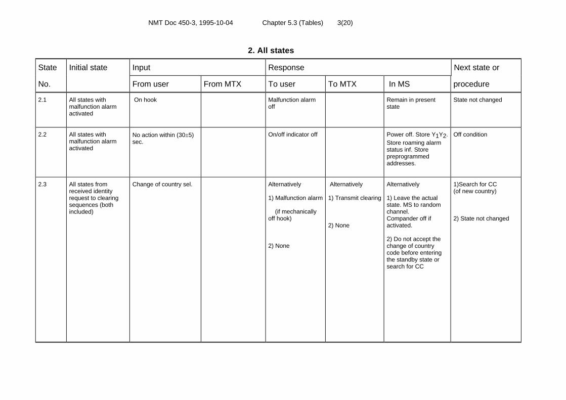
NMT Doc 450-3, 1995-10-04 Chapter 5.3 (Tables) 3(20)
2. All states
State Initial state Input Response Next state or
No. From user From MTX To user To MTX In MS procedure
2.1 All states withmalfunction alarmactivated
On hook Malfunction alarmoff
Remain in presentstate
State not changed
2.2 All states withmalfunction alarmactivated
No action within (30±5)sec.
On/off indicator off Power off. Store Y1Y2.Store roaming alarmstatus inf. Storepreprogrammedaddresses.
Off condition
2.3 All states fromreceived identityrequest to clearingsequences (bothincluded)
Change of country sel. Alternatively
1) Malfunction alarm
(if mechanicallyoff hook)
2) None
Alternatively
1) Transmit clearing
2) None
Alternatively
1) Leave the actualstate. MS to randomchannel.Compander off ifactivated.
2) Do not accept thechange of countrycode before enteringthe standby state orsearch for CC
1)Search for CC(of new country)
2) State not changed

NMT Doc 450-3, 1995-10-04 Chapter 5.3 (Tables) 4(20)
3. Standby state
State Initial state Input Response Next state or
No. From user From MTX To user To MTX In MS procedure
3.1 Standby CC with valid Y1Y2 Service ind. on Standby
3.2 Standby Call to MS Transmit acknowl. Wait for channel order
3.3 Standby Scanning order to MS Service ind. off Search for TC(scheme B1)
3.4 Standby Loss of CC lock Service ind. off MS initiates scanning Search for CC
3.5 Standby Off hook (dialled digitsmemory not empty)
Service ind. off Store CC channelnumber. MS to randomchannel
Search for TC(scheme A)
3.6 Standby Off hook (dialled digitsmemory empty.Roaming alarm ind. off)
Malfunction alarm Remain in presentstate (no signallinginitiated) MSelectrically on hook
Standby (withmalfunction alarmactivated)
3.7 Standby Off hook (roaming alarmactivated)
Service ind. off Store CC channelnumber. MS to randomchannel
Search for TC (scheme A)
3.8 Standby Change of countryselector
Service ind. off Clear Y2. Accept Y1according to selectedcountry. MS to randomchannel
Search for CC (of newcountry)

NMT Doc 450-3, 1995-10-04 Chapter 5.3 (Tables) 5(20)
4. Search for CC
State Initial state Input Response Next state or
No. From user From MTX To user To MTX In MS procedure
4.1 Search for CC No CC MS to next channel Search for CC
4.2 Search for CC Off hook (dialled digitsmemory not empty)
Malfunction alarm (MS to random chan.) Search for TC (scheme A)
4.3 Search for CC Off hook (dialled digitsmemory empty.Roaming alarm ind. off)
Remain in presentstate (no signallinginitiated)
Search for CC (withmalfunction alarmactivated)
4.4 Search for CC Off hook (roaming alarmactivated)
(MS to random chan.) Search for TC(scheme A)
4.5 Search for CC CC with previousY1Y2
Service ind. on Lock to CC Standby
4.6 Search for CC CC with new Y1Y2 MS to next channel(set test for roaming)
Search for CC (test forroaming)
4.7 Search for CC (testfor roaming)
No CC with previousY1Y2 detected in 2scans. New Y1Y2detected twice
Store new Y1Y2. Setroaming flag
Search for TC(roaming flag set)(scheme D)
Note: Previous Y1Y2 means match with the stored Y 1Y2

NMT Doc 450-3, 1995-10-04 Chapter 5.3 (Tables) 6(20)
5. Search for TC, scheme A
State Initial state Input Response Next state or
No. From user From MTX To user To MTX In MS procedure
5.1 Search for TC(scheme A)
TC with stored Y1Y2 Transmit seizure Wait for identity req.(scheme A)
5.2 Search for TC(scheme A)
No TC with storedY1Y2
MS to next channel Search for TC(scheme A)
5.3 Search for TC(scheme A)
No TC with storedY1Y2 in 15 scans
Malfunction alarmon
MS to any (random orprevious) channel. MSelectrically on hook
Search for CC (with malfunction alarmactivated)
5.4 Search for TC(scheme A)
On hook Clear dialled digitsdisplay
Clear dialled digitsmemory. MS toprevious CC
Search for CC

NMT Doc 450-3, 1995-10-04 Chapter 5.3 (Tables) 7(20)
6. Search for TC, MS on hook, no roaming flag, scheme B1
State Initial state Input Response Next state or
No. From user From MTX To user To MTX In MS procedure
6.1 Search for TC(scheme B1)
TC with stored Y1Y2 Transmit seizure10c
Wait for identity req.(scheme B1)
6.2 Search for TC(scheme B1)
No TC with storedY1Y2
MS to next channel Search for TC (scheme B1)
6.3 Search for TC(scheme B1)
No TC with storedY1Y2 within (10 ±1)sec. after received 2d
MS to random channel Search for CC
6.4 Search for TC(scheme B1)
Off hook Malfunction alarm.Clear dialled digitsdisplay
Proceed scheme B1.MS remainseleectrically on hook.Clear dialled digitsmemory
Search for TC(scheme B1)(malfunction alarmactivated)

NMT Doc 450-3, 1995-10-04 Chapter 5.3 (Tables) 8(20)
7. Search for TC, MS on hook, roaming flag set, scheme D
State Initial state Input Response Next state or
No. From user From MTX To user To MTX In MS procedure
7.1 Search for TC(scheme D)
TC with stored Y1Y2(new)
Transmit roamingupdating seizure
Wait for identity req.(scheme D)
7.2 Search for TC(scheme D)
No TC with storedY1Y2 (new)
MS to next channel Search for TC(scheme D)
7.3 Search for TC(scheme D)
No TC with storedY1Y2 (new) in 15scans
Clear Y2. No Y1Y2 isprevious Y1Y2 . MS toany (random orprevious) channel
Search for CC(test for roaming)
7.4 Search for TC(scheme D )
Off hook Roaming alarmindicator on
MS to randomchannel. Clearroaming flag
Search for TC(scheme A)
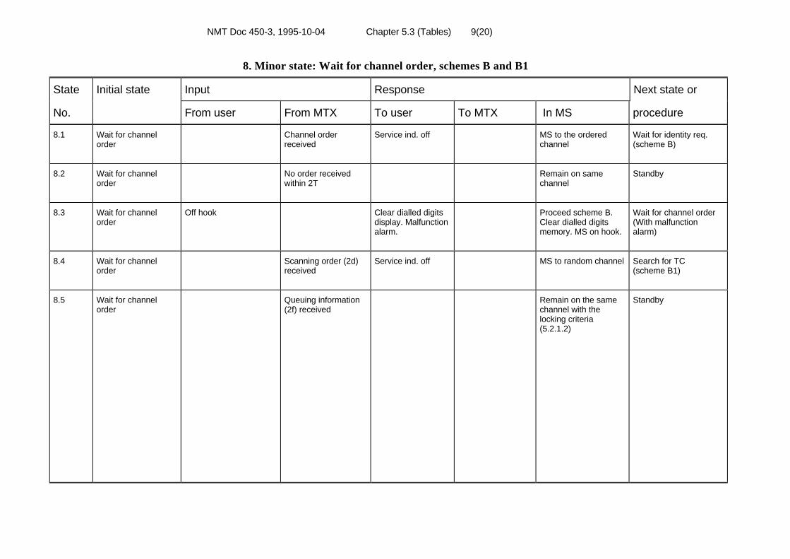
NMT Doc 450-3, 1995-10-04 Chapter 5.3 (Tables) 9(20)
8. Minor state: Wait for channel order, schemes B and B1
State Initial state Input Response Next state or
No. From user From MTX To user To MTX In MS procedure
8.1 Wait for channelorder
Channel orderreceived
Service ind. off MS to the orderedchannel
Wait for identity req.(scheme B)
8.2 Wait for channelorder
No order receivedwithin 2T
Remain on samechannel
Standby
8.3 Wait for channelorder
Off hook Clear dialled digitsdisplay. Malfunctionalarm.
Proceed scheme B.Clear dialled digitsmemory. MS on hook.
Wait for channel order(With malfunctionalarm)
8.4 Wait for channelorder
Scanning order (2d)received
Service ind. off MS to random channel Search for TC(scheme B1)
8.5 Wait for channelorder
Queuing information(2f) received
Remain on the samechannel with thelocking criteria(5.2.1.2)
Standby

NMT Doc 450-3, 1995-10-04 Chapter 5.3 (Tables) 10(20)
9. Minor state: Wait for identity request, scheme A
State Initial state Input Response Next state or
No. From user From MTX To user To MTX In MS procedure
9.1 Wait for identity req.(scheme A)
Identity req. and/orauthentication req.received
Transmit identityfollowed by signedresponse (ifauthenticationrequest received),and idle frames.See note below!
Wait for proceed tosend (scheme A)
9.2 Wait for identity req.(scheme A).First attempt
No identity req.received within T
MS to random channel Search for TC(scheme A)
9.3 Wait for identity req.(scheme A).Second attempt
No identity req.received within T
Malfunction alarm.Clear dialled digitsdisplay
MS to previous CC.MS electrically onhook. Clear dialleddigits memory
Search for CC (with malfunction alarmactivated)
9.4 Wait for identity req.(scheme A)
Forced releasereceived
Malfunction alarm.Clear dialled digitsdisplay
Transmit clearing MS to previous CC.MS electrically onhook. Clear dialleddigits memory
Search for CC(with malfunction alarmactivated)
9.5 Wait for identity req.(scheme A)
On hook Clear dialled digitsdisplay
MS to previous CC.Clear dialled digitsmemory
Search for CC
Note: The MS shall start transmission of frame 10b/12 after analysis of the frame following next to frame 3b. The MS shall accept the first correctly received frame 7 from MTX,received within T after start transmit frame 10b, or until frame 5a(L=3/11) is received.
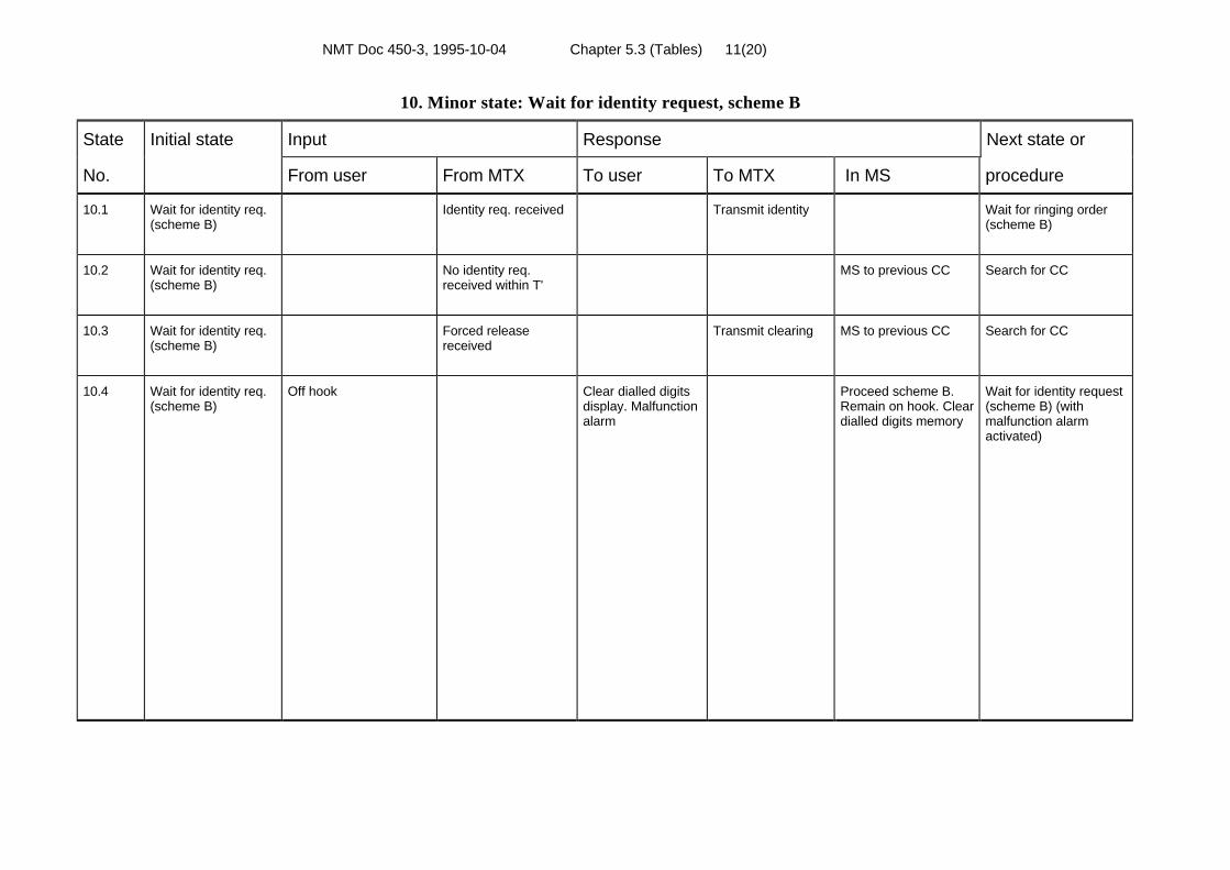
NMT Doc 450-3, 1995-10-04 Chapter 5.3 (Tables) 11(20)
10. Minor state: Wait for identity request, scheme B
State Initial state Input Response Next state or
No. From user From MTX To user To MTX In MS procedure
10.1 Wait for identity req.(scheme B)
Identity req. received Transmit identity Wait for ringing order(scheme B)
10.2 Wait for identity req.(scheme B)
No identity req.received within T'
MS to previous CC Search for CC
10.3 Wait for identity req.(scheme B)
Forced releasereceived
Transmit clearing MS to previous CC Search for CC
10.4 Wait for identity req.(scheme B)
Off hook Clear dialled digitsdisplay. Malfunctionalarm
Proceed scheme B.Remain on hook. Cleardialled digits memory
Wait for identity request(scheme B) (withmalfunction alarmactivated)

NMT Doc 450-3, 1995-10-04 Chapter 5.3 (Tables) 12(20)
11. Minor state: Wait for identity request, scheme B1
State Initial state Input Response Next state or
No. From user From MTX To user To MTX In MS procedure
11.1 Wait for identity req.(scheme B1)
Identity req. received Transmit identity Wait for ringing order
11.2 Wait for identity req.(scheme B1)First attempt
No identity req.received within T
Search for TC(scheme B1)
11.3 Wait for identity req.(scheme B1)Second attempt
No identity req.received within T
MS to random initialchannel
Search for CC
11.4 Wait for identity req.(scheme B1)
Forced releasereceived
Transmit clearing MS to random initialchannel
Search for CC
11.5 Wait for identity req.(scheme B1)
Off hook Clear dialled digitsdisplay. Malfunctionalarm
Proceed scheme B1.Remain on hook. Cleardialled digits memory
Wait for identity req.(scheme B1) (withmalfunction alarmactivated)

NMT Doc 450-3, 1995-10-04 Chapter 5.3 (Tables) 13(20)
12. Minor state: Wait for identity request, scheme C and C2'
State Initial state Input Response Next state or
No. From user From MTX To user To MTX In MS procedure
12.1 Wait for identityrequest (scheme C)
Identity requestreceived
(Conversation onnew TC)
Transmit identity Open speech path.Throughconnectsupervisory signal
Conversation
12.2 Wait for identityrequest (scheme C)
No identity requestreceived within T'
(Conversation onprevious TC)
MS to previous TC.Open speech path.Throughconnectsupervisory signal
Conversation
12.3 Wait for identityrequest(scheme C and C2')
Forced releasereceived
Malfunction alarm Transmit clearing MS to previous CC.Compander off ifactivated.
Search for CC (withmalfunction alarmactivated)
12.4 Wait for identityrequest (scheme C)
On hook Transmit clearing Wait for forced releasein max. T.MS to previous CC .Compander off ifactivated.
Search for CC
12.5 Wait for identityrequest (scheme C2')
RF level above limit A20 ± 4 dB (µV) E.M.F.
Transmit identity(1 frame)
Open speech path.Throughconnectsupervisory signal
Conversation
12.6 Wait for identityrequest (scheme C2')
RF level below limit A20 ± 4 dB (µV) E.M.F.Identity req. received
Transmit identity Open speech path.Throughconnectsupervisory signal
Conversation
12.7 Wait for identityrequest (scheme C2')
RF level below limit A20 ± 4 dB (µV) E.M.F.Identity req. notreceived within T
MS to previous TC.Open speech path.Throughconnectsupervisory signal
Conversation

NMT Doc 450-3, 1995-10-04 Chapter 5.3 (Tables) 14(20)
13. Minor state: Wait for identity request, scheme D
State Initial state Input Response Next state or
No. From user From MTX To user To MTX In MS procedure
13.1 Wait for identity req.(scheme D)
Identity req. received Transmit roamingupdating seizurefollowed by idleframes
Wait for roamingupdating confirmation(scheme D)
13.2 Wait for identity req.(scheme D)First attempt
No identity req.received within T
MS to random channel Search for TC(scheme D)
13.3 Wait for identity req.(scheme D)Second attempt
No identity req.received within T
Roaming alarmindicator on
MS to "new" CC Search for CC(with roaming alarmactivated)
13.4 Wait for identity req.(scheme D)
Forced releasereceived
Roaming alarmindicator on
Transmit clearing MS to "new" CC Search for CC(with roaming alarmactivated)
13.5 Wait for identity req.(scheme D)
Off hook Malfunction alarm.Clear dialled digitsdisplay
Proceed scheme D.Clear dialled digitsmemory
Wait for identity req.(scheme D) (withmalfunction alarmactivated)

NMT Doc 450-3, 1995-10-04 Chapter 5.3 (Tables) 15(20)
14. Minor state: Wait for roaming updating confirmation, scheme D
State Initial state Input Response Next state or
No. From user From MTX To user To MTX In MS procedure
14.1 Wait for roamingupdating confirmation(scheme D)
Received roamingupdating confirmation
Roaming alarmindicator off (ifactivated)
Transmit clearing MS to "new" CC Search for CC
14.2 Wait for roamingupdating confirmation(scheme D)
No roaming updatingconfirmation receivedwithin T
Roaming alarmindicator on
Transmit clearing MS to "new" CC.Wait for forced releasein max. T
Search for CC(with roaming alarmactivated)
14.3 Wait for roamingupdating confirmation(scheme D)
Forced releasereceived
Roaming alarmindicator on
Transmit clearing MS to "new" CC Search for CC(with roaming alarmactivated)
14.4 Wait for roamingupdating confirmation(scheme D)
Off hook Malfunction alarm.Clear dialled digitsdisplay
Proceed scheme D.Clear dialled digitsmemory.
Wait for roamingupdating confirmation(scheme D) (withmalfunction alarmactivated)
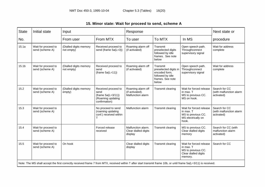
NMT Doc 450-3, 1995-10-04 Chapter 5.3 (Tables) 16(20)
15. Minor state: Wait for proceed to send, scheme A
State Initial state Input Response Next state or
No. From user From MTX To user To MTX In MS procedure
15.1a Wait for proceed tosend (scheme A)
(Dialled digits memorynot empty)
Received proceed tosend (frame 5a(L=3))
Roaming alarm off(if activated)
Transmitpreselected digitsfollowed by idleframes. See notebelow
Open speech path.Throughconnectsupervisory signal
Wait for addresscomplete
15.1b Wait for proceed tosend (scheme A)
(Dialled digits memorynot empty)
Received proceed tosend(frame 5a(L=11))
Roaming alarm off(if activated)
Transmitpreselected digits inencoded form,followed by idleframes. See notebelow
Open speech path.Throughconnectsupervisory signal
Wait for addresscomplete
15.2 Wait for proceed tosend (scheme A)
(Dialled digits memoryempty)
Received proceed tosend(frame 5a(L=3/11))(Roaming updatingconfirmation)
Roaming alarm off(if activated).Malfunction alarm
Transmit clearing Wait for forced releasein max. TMS to previous CC.MS on hook.
Search for CC(with malfunction alarmactivated)
15.3 Wait for proceed tosend (scheme A)
No proceed to send(roaming updatingconf.) received withinT
Malfunction alarm Transmit clearing Wait for forced releasein max. TMS to previous CC.MS electrically onhook.
Search for CC(with malfunction alarmactivated)
15.4 Wait for proceed tosend (scheme A)
Forced releasereceived
Malfunction alarm.Clear dialled digitsdisplay
Transmit clearing MS to previous CC.Clear dialled digitsmemory
Search for CC (withmalfunction alarmactivated)
15.5 Wait for proceed tosend (scheme A)
On hook Clear dialled digitsdisplay
Transmit clearing Wait for forced releasein max. TMS to previous CC.Clear dialled digitsmemory.
Search for CC
Note: The MS shall accept the first correctly received frame 7 from MTX, received within T after start transmit frame 10b, or until frame 5a(L=3/11) is received.
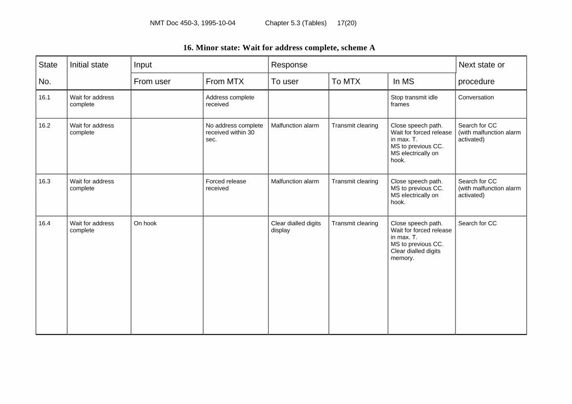
NMT Doc 450-3, 1995-10-04 Chapter 5.3 (Tables) 17(20)
16. Minor state: Wait for address complete, scheme A
State Initial state Input Response Next state or
No. From user From MTX To user To MTX In MS procedure
16.1 Wait for addresscomplete
Address completereceived
Stop transmit idleframes
Conversation
16.2 Wait for addresscomplete
No address completereceived within 30sec.
Malfunction alarm Transmit clearing Close speech path.Wait for forced releasein max. T.MS to previous CC.MS electrically onhook.
Search for CC(with malfunction alarmactivated)
16.3 Wait for addresscomplete
Forced releasereceived
Malfunction alarm Transmit clearing Close speech path.MS to previous CC.MS electrically onhook.
Search for CC(with malfunction alarmactivated)
16.4 Wait for addresscomplete
On hook Clear dialled digitsdisplay
Transmit clearing Close speech path.Wait for forced releasein max. T.MS to previous CC.Clear dialled digitsmemory.
Search for CC

NMT Doc 450-3, 1995-10-04 Chapter 5.3 (Tables) 18(20)
17. Minor state: Wait for ringing order, schemes B and B1
State Initial state Input Response Next state or
No. From user From MTX To user To MTX In MS procedure
17.1 Wait for first or nextringing order(scheme B (B1))
Ringing orderreceived
Ringing signal. Callreceived indicatoron
Generate ringingsignal. Call receivedindicator on
Wait for (next) ringingorder (scheme B (B1))
17.2 Wait for first ringingorder(scheme B (B1))
No ringing orderreceived within T
Transmit clearing Wait for forced releasein max. T.MS to previous CC.(MS to randomchannel in scheme B1)
Search for CC
17.3 Wait for first or nextringing order(scheme B (B1))(with malfunctionalarm activated)
Ringing orderreceived
Malfunction alarm.Call receivedindicator on.Ringing signal
Generate ringingsignal. Call receivedindicator on
Wait for (next) ringingorder (scheme B (B1))with malfunction alarmactivated
17.4 Wait for first ringingorder(scheme B (B1))
Off hook Malfunction alarm Wait for (first) ringingorder (scheme B (B1))with malfunction alarmactivated
17.5 Wait for next ringingorder(scheme B (B1))
No ringing orderreceived within 30sec.
Transmit clearing Wait for forced releasein max. T. MS to previous CC.(MS to randomchannel in scheme B1)
Search for CC
17.6 Wait for next ringingorder(scheme B (B1))
Off hook Call receivedindicator off
Transmit B-answer Open speech path.Throughconnectsupervisory signal
Conversation
17.7 Wait for first or nextringing order(scheme B (B1))
Forced releasereceived
Transmit clearing MS to previous CC.(MS to randomchannel in scheme B1)
Search for CC

NMT Doc 450-3, 1995-10-04 Chapter 5.3 (Tables) 19(20)
18. Conversation state
State Initial state Input Response Next state or
No. From user From MTX To user To MTX In MS procedure
18.1 Conversation Channel order tosame channel (powerchange) received
Transmit identity Power change basedon Na info.
Conversation
18.2 Conversation Channel order toanother channel(frame 3a) received
Close speech path.Disconnectsupervisory signal. MSto ordered channel
Wait for identity request(scheme C)
18.3 Conversation Channel order toanother channel(frame 3c) received
Close speech path.Disconnectsupervisory signal. MSto ordered channel
Wait for identity request(scheme C2')
18.4 Conversation Identity req. Transmit identity Power change (ifordered)
18.5 Conversation Forced release Malfunction alarmon
Transmit clearing Close speech path.Disconnectsupervisory signal. MSto previous CC. MSelectrically on hook.Compander off ifactivated.
Search for CC (withmalfunction alarmactivated)
18.6 Conversation On hook Transmit clearing Close speech path.Disconnectsupervisory signal.Wait for forced releasein max. T.MS to previous CC,compander off ifactivated.
Search for CC

NMT Doc 450-3, 1995-10-04 Chapter 5.3 (Tables) 20(20)
18. Conversation state (cont)
State Initial state Input Response Next state or
No. From user From MTX To user To MTX In MS procedure
18.7 Conversation MS switched off byon/off switch
On/off indicator off Transmit clearing Wait for forced releasein max. T.MS to off condition.Compander off ifactivated.
Off condition
18.8 Conversation MS switched off byautonomous time out
On/off indicator off Transmit clearing Wait for forced releasein max. T.MS to off condition.Compander off ifactivated.
Off condition
18.9 Conversation
note: see 5.2.1.3
Activate compander(frame 5a (L=5))
Activate compander Conversation
18.10 Conversation
note: see 5.2.1.3
Deactivatecompander(frame 5a (L=7))
Deactivatecompander
Conversation
18.11 Conversation Identity andauthentication requestreceived.
Transmit identityfollowed by signedresponse.
Conversation
NMT Doc 450-3, 1995-10-04 Chapter 5.4 1(16)
5.4 FLOW DIAGRAMS FOR THE SIGNALLINGSCHEMES
The flow diagrams in paragraph 5.2.1 and in this paragraph are explanatoryguidelines only and are not exhaustive. They are not intended as detaileddesign schemes.
5.4.1 Main states for LCU (See flow diagrams Fig. 5.2)
This flow diagram gives the main states for the Logic and Control Unit andgives also the logical connection between them.
An explanation of the main principles for:
- Search for CC (Fig. 5.3)- Search for TC, MS off hook (Fig. 5.4)- Search for TC, roaming flag set, MS on hook (Fig. 5.5)- Search for TC, no roaming flag set, MS on hook (Fig. 5.6)
is given in the paragraphs 5.2.1.4. - 8.
5.4.2 Call MS →→ MTX (signalling scheme A). (See flow diagramFig. 5.7)
When the user makes a call attempt the MS shall initiate the proceduresearch for TC.
After locking to a traffic channel, the MS proceeds with the "call MS →MTX" procedure.
If roaming updating in scheme D is interrupted by MS off hook (combinedupdating and call) the roaming alarm shall be activated.
Transmit seizure
The MS shall transmit seizure (two frames 10b) with start T" after the end ofreceived frame 4 or 1b (see also paragraph 5.6.5).
Identity request received
The MS shall receive identity request (frame 3b) within T after havingtransmitted the seizure (frame 10b) above, in order to proceed the call.
If identity request is not received within T after having transmitted theseizure, the MS shall initiate a second search for TC in order to makeanother call attempt.
NMT Doc 450-3, 1995-10-04 Chapter 5.4 2(16)
Transmit identity
The MS shall transmit four frames 10b with start T'' after analyzing oneframe after the received frame 3b above.
Frame 5a (L=3/11) may be received during transmission of frames 10b, 11aor 12.
Digit transmission
The digits in the dialled digits memory are transmitted consecutively afterreceiving frame 5a (L=3/11). If frame 5a (L=11) is received, the digits shallbe transmitted in encoded form, based on the received RAND and the storedSAK in the MS. See also NMT Doc 450-1
If no RAND (but frame 5a (L=11)) has been received, the MS shall transmitfour frames 13a (L=1) and return to stand by. Frame 5a (L=6) and 5a(L=13/L=15) may be received during transmission of dialled digits. The digitframe transmission shall then stop immediately.
After the last digit has been transmitted frames 15 shall be transmitted untilframe 5a (L=6) has been received.
Encrypted digits transmission shall start immediately after frame 5a (L=11)has been received and frames 16 have been transmitted.
Turn off roaming alarm
When frame 5a (L=3/11) is received and if the roaming alarm is "on", theMS has been updated in the MTX and the alarm shall be turned "off".
Open loudspeaker and microphone
The speech path shall be opened when the MS has received 5a (L=3/11).However, the voice input circuit (microphone) is closed during datatransmission (see paragraph 5.5.4).
Note: T = 1107 ms (eight frames)T' = 553 ms (four frames)T'' = (30 ±2,5) msT''' = 277 ms (two frames)

NMT Doc 450-3, 1995-10-04 Chapter 5.4 3(16)
A. Call MS => MTX
1
6
Malfunction alarm
Open speech path,loop supervisorysignal
Transmit 2 x 14a(1 st digit)
Transmit 2 x 14b
Transmit 2 x 14a/b(last digit)
Transmit 15continuously
Transmit 2 x 14a(1st digit) encrypted
Transmit 2 x 14b(2nd digit) encrypted
Transmit 2 x 14a/b(last digit) encryptedTransmit 15
continuously
Transmitpreselecteddigits
no
no
yes
yes
Wait for addresscomplete
Stop transmitting 15
ConversationMalfunction alarm 2MS clearing(Fig. 5.12)
yes
no
no
yesRelease roamingalarm (if any)
Dialleddigits memory
empty?
**Transmit 4 frames 10bfollowed by idle frames 15, ifnecessary 2 frames 16 andthen idle frames 15continuously
Transmitter "on"
no
no
no
yes
yes
Wait foridentityrequest
First attempt
Transmitter "off"
Search for CC(Fig. 5.3)
Search for TC(Fig. 5.4)
A
Rest on N1 N2 N3
Transmitter "on"
T = 1107 ms (8 frames)T' = 553 ms (4 frames)T'' = (30 ± 2.5) msT''' = 277 ms (2 frames)
?
Transmit 4 frames of10b followed by idleframes15 continuosly
>
>
Transmit 10b(twoframes) T" afterreception of frame4 or 1b
no
yes
Receptionof 5a (L=3/11)
within T after starttransmit
15?
Receptionof 5a (L=6) within
30 sec. after trans-mitting last
digit?
MTXasking for
encrypted digits(i.e.) 5a(L=11)
received?
Receptionof 3b within T after
start transmit10b
Receivedframe 7 within1 frame after
receptionof 3b
Transmitter "on"
Notes:
**The MS shall start transmission of frame 10bafter analysis of the frame following next to frame 3b.The MS shall accept the first correctly received frame 7from MTX, received within T after start transmitframe 10 b, or until frame 5a (L=3/11) is received.
Transmitpreselecteddigits
Fig. 5. 7

NMT Doc 450-3, 1995-10-04 Chapter 5.4 4(16)
5.4.3 Call MTX => MS (signalling scheme B). (See flow diagramFig. 5.8)
When the MS is locked to CC it shall always be sensitive to frame 2a.
After having obtained Z X1..X6 match, the MS shall enter the "call MTX -MS" procedure.
Transmit acknowledge
The MS shall transmit a shortened frame 10a with start T'' after the end ofthe received frame 2a,(see paragraph 5.6).
The RF output power level from the MS shall be based on an analysis of N1,in a number of previously received frames on the channel or determined byN1 in frame 2a.
Received channel order
The MS shall be sensitive to:
- Channel order (frame 2b)- Scanning order (frame 2d)- Queuing information (frame 2f)- Call to MS (frame 2a)
during 2 T after transmission of acknowledge (frame 10a ).
If no channel order is received, the MS shall remain standby on the channel.
If channel order (frame 2b) is received the MS changes to TC Na Nb Nc.
If scanning order (frame 2d) is received the MS initiates search for TC, noroaming flag set, MS on hook, see paragraph 5.2.1.8.
If queuing information (frame 2f) is received the MS shall remain standby onthe channel.
If a repeated call is received, MS shall send a shortened frame as statedabove for an ordinary call to MS.
During wait for channel order the MS shall still check the criteria for lockingto the CC according to paragraph 5.2.1.2.
Received identity request (in signalling scheme B)
The identity request (frame 3b) must be received within T ' after reception ofchannel order (frame 2b).

NMT Doc 450-3, 1995-10-04 Chapter 5.4 5(16)
Ringing order
First ringing order (frame 5a (L=9)) is received within T after starttransmission of acknowledge (frame 10b).
After reception of ringing order, the MS shall generate ringing signalaccording to paragraph 3.7.1.
After reception of last ringing order, the MS shall wait for next ringing orderin (30 ±5) sec.
If no ringing order is received, the MS shall transmit clearing, return toprevious CC and enter the state search for CC.
B-answer
When MS goes "off hook", four frames 13a (L=14) shall be transmitted.

NMT Doc 450-3, 1995-10-04 Chapter 5.4 6(16)
B. Call MTX => MS
Transmitter "on"
Transmitter "on"
Transmitter "on"
Transmitter "on"
Transmitter "on"
Transmitter "off"
Transmitter "off"
Conversation
MS clearing(Fig. 5.12)
MS clearing(Fig. 5.12)
Search for CC(Fig. 5.3)
Wait for identity request
B
7
4
2
1 2
4
Transmit 10aon CC (N1N2N3) T"after reception of 2a
Store N1N2N3
Received2f?
Received2d?
Received2b?
Time ≤ 2T?
Standby(Fig. 5.2)
Search forTC(Fig. 5.6)
Generate ringing signalin MS and activate callreceived indicator
Wait for (next) ringing order
Standby(Fig. 5.2)
Malfunctionalarm on
?
MS "off hook"?
Open speech path andloop supervisory signal.Call received indicator off
Transmit B-answer4 frames 13a (L=14)
Generate ringingsignal in MS
Received5a (L=9) (within
30 sec)?
Received5a (L=9) within
T after starttransmitting
10b ?
3breceived
within T' afterreception of
2b ?
Wait for (first)ringingorder
Wait forchannelorder on CC
no
no
no
no
no
no
no
no
no
yes
yes
yes
yes
yes
yes
yesGo to TC NaNbNc
Transmit 4 frames 10b
yes
Note T = 1107 msT' = 553 msT'' = (30 ±2.5) msT''' = 277 ms
(4 frames)(8 frames)
(2 frames)
This sequence is overruled by reception offorced release from MTX, autonomous time-out or MS on hook.Remark:Malfunction alarm shall, if activated, turn offwhen the MS goes on hook.
The ringing signal shall have a duration ofapprox. 1 second.
yes
Fig 5.8

NMT Doc 450-3, 1995-10-04 Chapter 5.4 7(16)
5.4.4 Call MTX=>MS (signalling scheme B1). (See flow diagramFig. 5.9)
After successful completion of the state MS on hook, search for TC, noroaming flag set, MS enters signalling scheme B1.
After locking to the TC the MS transmits seizure (frame 10c) and waits foridentity request (frame 3b).
Received identity request (in signalling scheme B1)
The MS shall receive identity request (frame 3b) within T after havingtransmitted the seizure (frame 10c) above, in order to proceed with the call.
If identity request is not received within T after having transmitted theseizure (frame 10c) above, the MS shall initiate a second search for TC.
Transmit identity
The MS shall transmit four frames 10c with start T" after the end of thereceived frame 3b above.
Ringing order
First ringing order (frame 5a (L=9)) is received within T after starttransmission of acknowledge (frame 10c).
After reception of first ringing order, the MS shall wait for next ringing orderin (30 ±5) sec.
If no ringing order is received, the MS shall transmit clearing, return toprevious CC and enter the state search for CC.
B-answer
When MS goes "off hook", frame 13a (L=14) shall be transmitted.
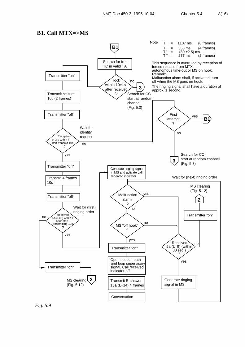
NMT Doc 450-3, 1995-10-04 Chapter 5.4 8(16)
B1. Call MTX=>MS
3
Note T = 1107 ms (8 frames)
Transmitter "on"
Transmitter "on"
Transmitter "on"
Transmitter "on"
Transmitter "on"
Transmitter "off"
Transmitter "off"
Wait foridentityrequest
Search for CCstart at random channel(Fig. 5.3)
MS clearing(Fig. 5.12)
Transmit 4 frames10c
in MS and activate callGenerate ringing signal
received indicator
Open speech pathand loop supervisorysignal. Call receivedindicator off
Conversation
Generate ringingsignal in MS
Received5a (L=9) (within
30 sec.)?
Wait for (next) ringing order
Malfunctionalarm
?
MS "off hook"?
B1
B1
3
2
2 Transmit B-answer13a (L=14) 4 frames
Transmit seizure10c (2 frames)
Receptionof 3 b within Tafterstart transmit 10c
?
Received5a (L=9) within T
after starttransmitting 10c
?
yes
yes
yes
yesyes
no
Firstattempt
?
no
no
nono
Wait for (first)ringing order
T' = 553 msT'' = (30 ±2.5) msT''' = 277 ms
(4 frames)
(2 frames)
This sequence is overruled by reception offorced release from MTX,autonomous time-out or MS on hook.Remark:Malfunction alarm shall, if activated, turnoff when the MS goes on hook.The ringing signal shall have a duration ofapprox. 1 second.
MS clearing(Fig. 5.12)
no
yes
.
Search for CCstart at randomchannel(Fig. 5.3)
no
Search for freeTC in valid TA
lockwithin 10±1safter received 2d
Fig. 5.9

NMT Doc 450-3, 1995-10-04 Chapter 5.4 9(16)
5.4.5 Switching call in progress (SCIP) (signalling scheme C)or MS power change.(See flow diagram Fig. 5.10)
When the MS receives a channel order (frame 3a) during conversation, it canbe either a power change order or a channel change order.
In the first case the MS shall change power to the ordered level indicated inNa, transmit identity (4 frames 10b) with new power indication and continuein conversation state.
In the second case the MS shall stop the transmitting and close the speechpath.
Then the MS changes to the new TC (N'1N'2N'3) after storing N1N2N3. TheMS shall use the RF power level indicated in N1 from received frame 3b.
If the change of channel fails for some reason (no identity check on TCN'1N'2N'3) the MS shall go back to the previous TC (N1N2N3). The MSshall use the RF power level indicated in the stored N1.
The change of channel may also imply power change depending on N1 inframe 3b on the new channel.
When the MS receives a channel order (frame 3c) during conversation, theMS shall initiate a fast switching call in progress-procedure (signallingscheme C2') if the channel numbers indicated in NaNbNc and N1N2N3 areequal.
The MS shall stop the transmitter, close the speech path and change to thenew TC (N'1N'2N'3) after storing N1N2N3. The power level on the newchannel is indicated in Na in frame 3c, if nothing else is indicated in possiblereceived frames 3b.
On the new channel the MS shall start transmit one frame 10b within 140 msafter reception of 3c, if the RF level exceeds level A criterion. The RF levelevaluation time shall be at least 40 ms. If the level A is not exceeded, the MSshall wait for identity request for T.

NMT Doc 450-3, 1995-10-04 Chapter 5.4 10(16)
C. Switching call in progress (SCIP) or MS power change
Transmitter "on" Transmitter "on"
Transmitter "off" Transmitter "off"
Store N1 N2 N3
Transmit 1 frame 10b
Store N1 N2 N3
CSequence overruled byreception of forced release,MS "on hook" orautonomous timeout
Transmit identity 10b,4 frames
Set new power levelbased on power bitsreceived in Na
Same channel?
Close speech path anddisconnect superv.sign. loopTransmitter "on"
Wait forchannelorder
Conversation on
Receivedframe 3c with
Receivedframe 3a with
Na Nb Nc
?
?
Close speech path anddisconnect superv.sign. loop
Go back to
Open speech path andconnect superv. sign. loop
Open speech path andconnect superv. sign. loop Open speech path and
connect superv. sign. loop
Transmit identity10b, 4 frames
ReceivedReceived
ReceivedRF signal above
20 dBµV?
identity requestframe 3b within Tafter reception
of 3c?
identity requestframe 3b within T'after reception
of 3a?
Receivedidentity request
frame 3b within Tafter reception
of 3c?
Transmit identity10b, 4 frames
Conversation onnew
yes
yes
yes
yes
yes
yes
yes
no
no
no
no
no
no
Note:T = 1107 ms (8 frames)T' = 553 ms (4 frames)T'' = (30 ±2.5) msT''' = 277 ms (2 frames)
N1 N2 N3
N1 N2 N3
Na Nb Nc = N1 N2 N3
N1 N2 N3
noGo to Na Nb Nc Go to Na Nb Nc
Fig. 5.10

NMT Doc 450-3, 1995-10-04 Chapter 5.4 11(16)
5.4.6 Updating roaming information (signalling scheme D).(See flow chart Fig. 5.11)
See also paragraph 5.4.2.
After having found a traffic channel in the same Y1Y2 as the new detectedcalling channel, the MS transmits frame 11a and waits for identity request.
If identity request is not received within T after start of transmitting frame11a, the MS shall initiate a second search for TC in order to make anotherroaming updating attempt.
If identity request is not received within T after start of transmitting frame11a, in the second attempt, the MS shall activate "Roaming alarm indicator"and go to the new CC and enter the state search for CC.
If roaming alarm state has been valid for 1 minute and a CC with the samenew Y2' is still received a second attempt for roaming updating may beinitiated. If this also fails and the stored Y2' remains the same, no moreattempts to roam except manual are allowed to the same new Y2'. Ifacoustic roaming alarm is used, it is recommended that it is generated onlyafter this second (optional) unsuccessful attempt.
If identity request is received within T the MS transmits roaming updatingseizure (4 frames 11a) and waits for roaming updating confirmation (frame5a (L=3)) within T.
When frame 5 a (L=3) is received, the MS has been updated in the MTX. MSthen turns off the roaming alarm indicator (if activated) and initiatesclearing.
If frame 5a (L=3) is not received within T after start transmit 11a, theroaming alarm indicator shall be activated, and MS shall initiate clearing.
5.4.7 MS clearing.(See flow chart Fig. 5.12)
When MS goes "on-hook", four frames 13a (L=1) shall be transmitted. Thecompander shall (if activated) be switched off.
If the MS user has activated the subscriber service "Immediate call transfer",MTX will respond to the MS clearing with frame 5a (L=13).
If this service is not activated the response from MTX will be frame 5a(L=15).
MS shall wait for frame 5a (L=13 or L=15) max. T after start of the firstframe 13a (L=1) in order to distinguish between the two clearing signalsfrom MTX. When the clearing signal has been detected, or after time-out,the MS returns to previous CC and enters the state search for CC.

NMT Doc 450-3, 1995-10-04 Chapter 5.4 12(16)
If MS goes "on-hook" during digit transmission, the dialled digits displayshall be cleared.
5.4.8 Forced release from MTX (See flow chart Fig. 5.13)
When MS receives frame 5a (L=13 or L=15), four frames 13a (L=1) shall betransmitted. The compander shall (if activated) be switched off.
The MS returns to previous CC and enters the state search for CC.
If forced release, frame 5a (L=13 or L=15) is received during digittransmission the dialled digits memory shall be cleared. The malfunctionalarm shall be activated (ref. paragraph 3.7.2.)
5.4.9 Authentication during conversation (See flow chart Fig.5.14)
When MS receives identity and authentication request the MS shall transmitfour frames 10b followed by idle frames 15, if necessary and two frames 16.
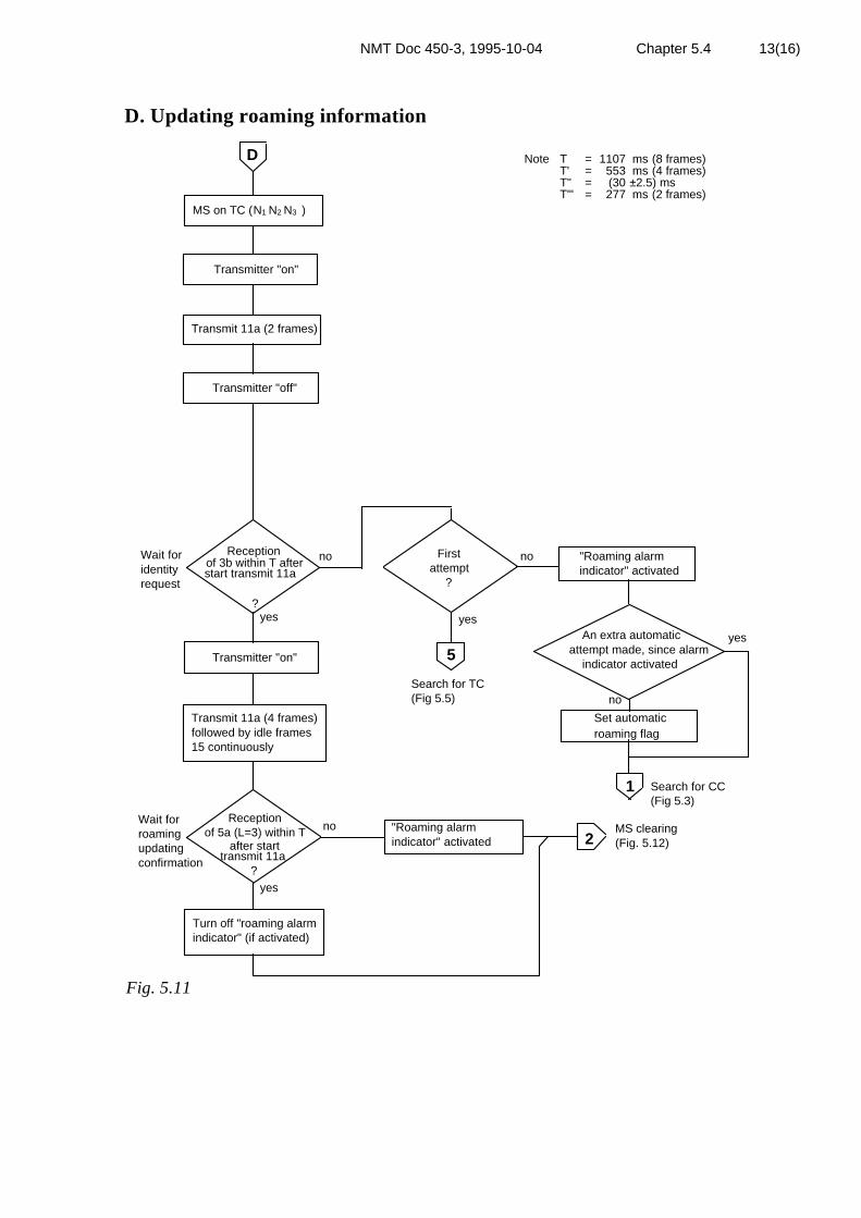
NMT Doc 450-3, 1995-10-04 Chapter 5.4 13(16)
D. Updating roaming information
An extra automaticattempt made, since alarm indicator activated
D
5
1
2
Transmitter "on"
Transmitter "on"
Transmitter "off"
Note T = 1107 ms (8 frames)T' = 553 ms (4 frames)T'' = (30 ±2.5) msT''' = 277 ms (2 frames)
Search for TC(Fig 5.5)
Search for CC(Fig 5.3)
MS clearing(Fig. 5.12)
Wait for identity request
Receptionof 5a (L=3) within T
after starttransmit 11a
?
MS on TC ( )N1 N2 N3
Transmit 11a (2 frames)
"Roaming alarmindicator" activated
Transmit 11a (4 frames)followed by idle frames15 continuously
"Roaming alarmindicator" activated
Turn off "roaming alarmindicator" (if activated)
Wait for roaming updating confirmation
Receptionof 3b within T afterstart transmit 11a
?yes
yes
Firstattempt
?
nono
no
yes
Set automaticroaming flag
yes
no
Fig. 5.11

NMT Doc 450-3, 1995-10-04 Chapter 5.4 14(16)
E. MS clearing
Transmitter "off"
Conversation
On hook
Close speech path if openand disconnect supervisorysignal loop if through-connected
Transmit clearing signal4 frames 13a (L=1)
Activate the immediatecall transfer indicatorif L=13 (Option)
MSoff hook
?Malfunction alarm
Search for CC(Fig. 5.3)
yes
no
1
2
yes
no
Received
Mobile station "on hook" or clearinginitiated by the mobile station.
Note T = 1107 msT' = 553 msT'' = (30 ±2.5) msT''' = 277 ms
(8 frames)(4 frames)
(2 frames)
5a (L=13 or L=15)within T after start
(L=1)transmit 13a
?
Fig 5.12

NMT Doc 450-3, 1995-10-04 Chapter 5.4 15(16)
F. Forced release
Conversation/signalling
Reception of clearingsignal 5a (L=13 or L=15)from MTX
Close speech path
Transmit release guard4 frames 13a (L=1)
Transmitter "off"
MSoff hook
?Malfunction alarm
Search for CC(Fig. 5.3)
Fixed subscriber "on hook" or forcedrelease for MTX
Note T = 1107 msT' = 553 msT'' = (30 ±2.5) msT''' = 277 ms
(8 frames)(4 frames)
(2 frames)
1
yes
no
Fig. 5.13

NMT Doc 450-3, 1995-10-04 Chapter 5.4 16(16)
Authentication during conversation
Conversation
Conversation
Reception of 3band 7 in consecutive
frames ( max T )
Transmit 4 frames 10bfollowed by idle frames 15, ifnecessary 2 frames 16
Note T = 1107 ms (8 frames) T' = 553 ms (4frames) T'' = (30 ± 2.5 ms) T''' = 277 ms (2 frames)
Fig 5.14

NMT Doc 450-3, 1995-10-04 Chapter 5.5 1(2)
5.5 SIGNALLING EQUIPMENT FOR 1200 BAUD FFSK
5.5.1 General description
Exchange of signals between MTX and MS is performed by means of 1200baud FFSK binary signalling.
The main characteristics and requirements for the FFSK signalling systemand equipment are dealt with in NMT Doc 450-1.
5.5.2 FFSK modulation in MS
Pre-emphasis
The FFSK signal shall be modulated in such a way that it is influenced by apre-emphasis similar to that applied to the voice input circuit. The signalshall be introduced into the transmitter after the audio muting device(paragraph 2.2.16) and shall not be affected by the compressor device.
Deviation
The FFSK signal shall produce a mean RF frequency deviation of(±3,5±0,5) kHz under normal and extreme test conditions. See alsoparagraph 1.3.8.2.
Group delay distortion
The distortion of the transmitted FFSK signals shall be measured accordingto paragraph 6.1.6.
5.5.3 FFSK signal receiver
The overall performance requirements for the FFSK signalling receptioncapability are specified in paragraph 6.1.7. The FFSK signals shall not beprocessed in the expander.
5.5.4 Splitting in MS
Encoding
When the MS transmits an FFSK signal, the voice input circuit and thesupervisory signal loop shall automatically be closed by the muting device.See paragraph 2.2.16. However, the supervisory signal loop shall remainthrough connected during MFT and Register recall signalling.

NMT Doc 450-3, 1995-10-04 Chapter 5.5 2(2)
Decoding
After reception of the frame synchronisation and before error correction, it ischecked whether the following six information bits all have the value 0. Ifso, the audio output is muted. The muting device used is specified inparagraph 2.3.21. Opening of the audio path is delayed (277 ±10) ms afterreception of the last frame synchronisation.
The audio output shall not be muted by noise or signal if the noise or signalis below a level of (-18±3) dB relative to the nominal level of the modem.
5.5.5 FFSK signalling detection time
The FFSK signalling receiver shall inform the Logic and Control Unitwhether the RF channel is modulated with an FFSK signal or not.
This information (about RF channel N+1) shall be provided within 20 msafter the moment the Logic and Control Unit ordered the transceiver toswitch from RF channel N to RF channel N+1.

NMT Doc 450-3, 1995-10-04 Chapter 5.6 1(3)
5.6 TIMING IN THE MS
All time tolerances given are valid under normal and extreme test conditions.
5.6.1 Time constants in the signalling procedure
The time constants used in performing the signalling procedures shall be thefollowing multiples of the time needed to transmit a 1200 baud signallingframe.
T = 1107 ms (eight frames)T' = 553 ms (four frames)T'' = (30 ±2,5) msT''' = 277 ms (two frames)
5.6.2 Timing between the signalling directions in MS
All timing in the signalling is specified with reference to the end of thereceived frame.
Definitions
The time skew
The time elapsed from the end of a received frame to the end of a partlyoverlapping transmitted frame is called the time skew. Fig. 5.15 shows anexample with a time skew of Ts ms.
Received frame
Transmitted frame
Ts
t
Fig 5.15 Time skew
The response time of the MS is the time elapsed from the end of the receivedmessage to the end of the transmitted message (answer). Thus the responsetime will be an integral number of frame times plus the time skew. Fig. 5.16shows an example of a response time of one frame plus a time skew of Ts.

NMT Doc 450-3, 1995-10-04 Chapter 5.6 2(3)
Ts
Receivedmessage
Timeskew
Response time Tr
Transmittedmessage
Fig 5.16 Response time
5.6.3 Timing of call acknowledgement on calling channel
After receiving a call on calling channel the MS shall start to transmit frame10a within (30±2,5) ms.
In order to decrease the risk of interference between two subsequent frameson the same channel, frames 10a shall be shortened frames where the bitsafter Y114 are deleted. The transmitter in the MS shall, however, be closedafter 117 ms after the starting point of bit sync, i.e. the transmitter shall beclosed after Y114 has been sent.
See Fig. 6.3.
5.6.4 Timing of transmission of frames 10b, 10c, 11a, 11b and12
The timing of transmission and tolerances specified in paragraph 5.6.3 fortransmission of frames 10a is also valid at transmission of frames 10b, 10c,11a, 11b and 12, and other frames which are transmitted from MS as aresponse of frames from MTX on the actual channel.
5.6.5 Timing of seizure on traffic channel
The response time for seizure, frames 10b, 10c, 11a, 11b and 12, shall be oneframe time plus a time skew of (30±2,5) ms after the detection of frame 4,free traffic channel indication, see Fig. 5.16. The start-up and decay timetolerances shall be the same as for the call acknowledgement frame 10a.

NMT Doc 450-3, 1995-10-04 Chapter 5.6 3(3)
5.6.6 Autonomous time-out
A timer, electrically separate from and independent of all other logicfunctions, must be running continuously whenever power is applied to theMS. Sufficient reset commands must be interspersed throughout the Logicand Control Unit to ensure that the timer never expires as long as the propersequence of operations is taking place. If the timer expires, a failure isassumed and the power must be switched off the MS.
The time allowed for the timer is (30±5) seconds under normal and extremetest conditions.
One of the functions of the timer is to switch off power when the MS istransmitting and no RF carrier is detected (see paragraph 2.3.6) within thespecified time. Bursts of RF carrier up to 1 s are not considered.
If an autonomous time-out occurs because of loss of RF input signal, the MSshall enter off condition according to paragraph 5.2.1.1. If time-out occursbecause of some malfunction or failure in hardware or software, e.g.continuous transmitting on calling channel or during scan, it is required thatthe power is switched off immediately, but the failure may prevent the MSfrom storing the information mentioned in paragraph 5.2.1.1.
Another example for the use of the timer is, that if the MS receivesFFSK-signalling continuously for (30 ±5) sec in conversation state, the timershall switch off the power.
In conversation state the MS shall transmit clearing immediately before thetimer switches off the power.
The power "on/off" switch must be switched manually "on" before thestation may return to normal operation.

NMT Doc 450-3, 1995-10-04 Chapter 5.7 1(2)
5.7 TRANSCEIVER INTERFACE
5.7.1 RF power control in MS
The RF output power level from the MS is based on the information receivedfrom the MTX. In MS the Logic and Control Unit gives control signals"carrier on/off" and power level "high", "medium" and "low" to thetransceiver.
5.7.1.1 MTX controlled maximum RF output power
The MTX controls the power level of the MS by means of power bit No. 2and 3 in N1 or Na (high power 11, medium power 10, low power 01 and 00)in the channel numbers of signalling frames 1, 2a, 3a, 3b, 3c, and 4 in thedirection MTX to MS. The same combination N1 N2 N3 is returned in thesignalling to the MTX. The MS shall be able to reduce and increase thepower level on order from MTX according to the following table.
Power level Power bits MS
High power 11 PH = 15 W ± 1.5 dBor
PH = 7 W ± 1.5 dB
Medium power 10 PM = 15 W - (10 ± 3 dB)
Low power 01 PL = 15 W - (20 ± 3 dB)
Low power 00 PL = 15 W - (20 ± 3 dB)
Measurements are made under normal and extreme test conditions.
In digits N1 and Na, the least significant bit (bit no. 4) denotes the hundredsdigit in the channel number. Bit no.1, which from outset shall have the value"0", is reserved for future use.
In signalling between MTX and BS, the first three bits in N1 and Nashall have the value 011 in both directions. However, between MTXand BS special values and meanings of N1 may be used (see paragraph4.3.1).

NMT Doc 450-3, 1995-10-04 Chapter 5.7 2(2)
The MS output power shall be controlled in the following way:
-For signalling frames on channel N1 N2 N3 not containing a channel orderNa Nb Nc, the power bits in N1 shall control the MS power level. Signallingframes in direction MS→MTX shall have the same power bits in N1 as inthe received frames from MTX.
-For signalling frames on channel N1 N2 N3 containing a channel orderNa Nb Nc, the MS power shall be controlled by the power bits in Na.Signalling frames in the direction MS→MTX shall have the same powerbits in N1as received from MTX in Na.
5.7.1.2 Autonomous power control in MS
If the mean RF level received in MS during conversation is above 55 dB(µV) E.M.F. ±5 dB for 5 seconds, the RF output power shall be reduced tolow power. In the signalling towards MTX, however, the received power bitsfrom MTX shall be used.
When the received mean RF level during conversation decreases to below45 dB (µV) E.M.F. ±5 dB for 5 seconds, the RF output level shall beincreased to the maximum RF output power indicated by the MTXsignalling. The hysteresis shall be at least 8 dB.
5.7.2 RF frequency control
The RF frequency of the transceiver is directly controlled by the Logic andControl Unit.
The received channel number given in N1N2N3 is coded according to NMTDoc 450-1.
5.7.3 Audio muting (See paragraphs 2.2.16, 2.3.21 and 5.5.4).
The audio input circuit and the audio output circuit are muted by controlsignals from Logic and Control Unit in accordance with signalling schemes,flow charts and state tables.
5.7.4 RF carrier detector
RF carrier detector shall inform the Logic and Control Unit and autonomoustime-out device whether an RF carrier is present or not. See also paragraph2.3.6.
NMT Doc 450-3, 1995-10-04 Chapter 6 1(9)
6. SYSTEM TESTS
The Logic and Control Unit is checked together with the transceiver by anumber of RF tests.
6.1 PERFORMANCE TESTS
6.1.1 Signalling sensitivity measured by call receptionprobability
This test corresponds to the test in paragraph 2.3.7.
Call reception probability is defined as the probability of receiving frame 10afrom the MS after having sent frame 2a (with the identification of the MS) tothe MS during the RF-conditions specified in the following paragraphs.
a) An RF-signal with a level of 0 dB (µV) E.M.F. (50 ohms) modulatedwith a frame 1a to a mean frequency deviation of ±3,5 kHz is applied to theantenna. Once per 86 frames, frame 2a with the identification of the MS istransmitted. During the time of the middle 66 frames between two calls tothe MS, the RF-level is increased to 15 dB (µV) E.M.F.
b) Same as in case a) but with an RF level of 3 dB (µV) E.M.F. and a meanfrequency deviation of ±1,75 kHz.
For both cases the requirement is minimum 95% call reception probability.
6.1.2 Co-channel data rejection
This test corresponds to the test in paragraph 2.3.8. The wanted signal withmodulation as in paragraph 6.1.1a shall have a level of 3 dB (µV) E.M.F.,and the unwanted signal with the same type of modulation but from a sourceindependent from the source used for the wanted signal shall have a level of-5 dB (µV) E.M.F.
The requirement is minimum 95% call reception probability.
6.1.3 Adjacent RF-signal decoding degradation
This test corresponds to the test in paragraph 2.3.9. The wanted signal withmodulation as in paragraph 6.1.1a shall have a level of 3 dB (µV) E.M.F.,and the unwanted signal level with modulation as in paragraph 6.1.2 shall be70 dB (µV) E.M.F.
The requirement is minimum 95% call reception probability.

NMT Doc 450-3, 1995-10-04 Chapter 6 2(9)
6.1.4 RF intermodulation decoding degradation
This test corresponds to the test in paragraph 2.3.12. The wanted signal,modulated as in paragraph 6.1.1a, shall have a level of 3 dB (µV) E.M.F.,and the two unwanted signals, one unmodulated and one modulated withrandom data signals to a mean frequency deviation of ± 3.5 kHz, shall have alevel of 70 dB (µV) E.M.F.
The requirement is minimum 95% call reception probability.
6.1.5 Signalling sensitivity in presence of RF signal fadingmeasured by call reception probability
The test is carried out in the same way as in paragraph 6.1.1a, but with afading simulator (Rayleigh) connected between the system simulator andMS. The test shall be made at simulated vehicle speeds of 10, 50, and 90km/h.
The requirement is 95% call reception probability for an RF signal level withan r.m.s. value of 10 dB (µV) E.M.F.
Note: The fading simulator may consist of 2 non-correlated digital pseudo-random generators with 3rd order digital filters to shape the noise powerspectra. The bandwidth corresponds to the doppler shift of the simulatedspeed. The two noise sources modulate two RF signals 90° out of phase. Itcan be shown that the combined signal has a Rayleigh distributed amplitude.
6.1.6 Data signal distortion
The distortion of the transmitted data signal from the MS is measured inaccordance with a measuring set-up shown in Fig. 6.1. The MS shall becontinuously modulated with normal data test modulation as defined inparagraph 1.3.8.2.
The error rate is analysed for different S/N ratios. The required S/N ratio forerror rate 10-4 is compared with the S/N ratio required for the same error ratewhen the reference FFSK transmitter is used (see NMT Doc 450-1).
For the error rate 10-4, the increase in S/N when measuring the MS shall beless than 0,5 dB compared with the reference measurement.

NMT Doc 450-3, 1995-10-04 Chapter 6 3(9)
MS R
D
DEM Erroranalyser
N
+
G
900 - 2100 Hz
MS - mobile station under testD - reference FFSK transmitterR - reference RF receiver with de-emphasisNG - noise generatorDEM - reference FFSK demodulator
Fig. 6.1 Measuring set-up
6.1.7 Ability to interpret distorted data signals
The distortion of data signals received by the MS consists mainly of groupdelay distortion, stemming from the connection MTX-BS and to a lesserextent from the BS circuitry. The ability of the MS to interpret data signalswith group delay distortion is measured by feeding the MS with an RF signalmodulated by predistorted data signals. The RF signal shall be modulated toan average frequency deviation of ±3,5 kHz, using the same test procedure asin paragraph 6.1.1a. The modulating signal shall be fed through a distortioncircuit with a group delay characteristic as shown in Fig. 6.2.
The required RF input signal level for 95% call reception probability shallnot exceed the level necessary for 95% call reception probability measuredwithout the distortion circuit by more than 1 dB.

NMT Doc 450-3, 1995-10-04 Chapter 6 4(9)
± Relative group delay (ms)
0
0,1
0,2
0,3
0,4
0,5
0,6
0,7
900 1200 1500 1800 2100 Frequency (Hz)
Fig. 6.2 Group delay of distortion circuit
6.2 TIME CONSTANTS
The following time constants are tested as described below. All requirementsand time tolerances shall be fulfilled under normal as well as extreme testconditions.
6.2.1 Receiver switching time to next channel including FFSKdetection time
The receiver switching time to next channel including FFSK detection timeshall not exceed 20 ms.
6.2.2 Transmitter start-up times
6.2.2.1 Definition
The transmitter reaction time is the time elapsed between the end of thecalling frame (2a) and the beginning of the call acknowledgement frame(10a) indicated as t3 in fig. 6.3.The following partial times are of interest:
The time elapsed from the end of the calling frame until the transmitteroutput power is 40 dB below its steady-state value is indicated as t1 in fig.6.3.
The time elapsed from the transmitter output power reaches a value 2 dBbelow its steady-state output power until the beginning of the callacknowledgement frame is indicated as t2 in fig. 6.3.

NMT Doc 450-3, 1995-10-04 Chapter 6 5(9)
Because of the reaction time of the base station squelch, the MS must alwayswait t2 before data signalling starts. See also paragraph 5.6.
6.2.2.2 Requirements:
t1 ≥ 14 mst2 ≥ 10 ms
6.2.3 Call acknowledgement on CC
The length of call acknowledgement is indicated as t4 in fig. 6.3. The time isminimum 117 ms (determined by the parameters of the signalling system).
6.2.4 Transmitter awake time
The transmitter awake time is defined as the time elapsed from the end of thecalling frame (2a) until the transmitter output power has decayed to a value40 dB below its steady-state value and is indicated as t5 in fig. 6.3. Themaximum length is 153 ms.
6.2.5 Switching time to ordered channel
6.2.5.1 Definition
Switching time to ordered channel is the time elapsed between the end of areceived channel order to an arbitrary channel (frames 2b and 3a) and theearliest moment MS is capable of reading received frames on the newordered channel.
6.2.5.2 Method of measurements
Two RF signals with a level of 10 dB (µV) E.M.F. are applied to the MSantenna terminal. RF signal A on channel N1N2N3 shall, according to thesignalling schemes, send a channel order to an arbitrary channel N'1N'2N'3.RF signal B is modulated with a frame giving a response in MS. The timeskew between channel order frame on channel N1N2N3 and the frame on thechannel N'1N'2N'3 is varied until shortest possible time is elapsed betweenchannel order and the response in MS. The time skew between the frame onchannel N1N2N3 and the frame on channel N'1N'2N'3 is equal to the definedswitching time.
6.2.5.3 Requirements
Switching time to ordered channel shall not exceed 40 ms.

NMT Doc 450-3, 1995-10-04 Chapter 6 6(9)
6.2.6 Transient behaviour of the transmitter
6.2.6.1 Definitions
The transient frequency behaviour of the transmitter is the variation in timeof the transmitter frequency difference from the nominal frequency of thetransmitter when the RF output power is switched on and off.
6.2.6.2 Method of measurement
The transient timings (switch on/off cases) and the frequency errorsoccurring during these periods of time can be measured by means of aspectrum analyzer and a modulation analyzer. See fig 6.4.
Two signals shall be connected to the discriminator via the combiningnetwork.
The transmitter (D.U.T.) shall be connected to a 50 ½ power attenuator.
The output of the power attenuator shall be connected to the discriminatorvia one input of the combining network.
The test signal shall be connected to the second input of the combiningnetwork.
The test signal shall be adjusted to the nominal frequency of the transmitter.
The test signal shall be modulated by a frequency of 1 kHz with a deviationof 12.5 kHz.
The test signal shall be adjusted to correspond to -40 dB of the power of thetransmitter under test measured at the input of the discriminator. This levelshall be maintained throughout the measurement.
The spectrum analyzer is set to measure and display power as a function oftime ("zero span mode", bandwidth as broad as possible )
The video output (ad) of the analyzer and the frequency output (fd) of themod. analyzer (discriminator) shall be connected to a storage oscilloscope.
The display will show the 1 kHz test signal continuously.
The storage oscilloscope shall then be set to trigger on the channelcorresponding to the amplitude (ad) input, rising edge.
The transmitter shall then be switched on.

NMT Doc 450-3, 1995-10-04 Chapter 6 7(9)
The result of the change in the power ratio between the test signal and thetransmitter input will, due to the capture ratio of the discriminator, producetwo separate sides on the picture, one showing the 1 kHz test signal, theother the frequency of the transmitter versus time.
The moment when the 1 kHz test signal is completely suppressed isconsidered to provide ton.
The result shall be recorded as frequency error versus time.
The transmitter shall remain switched on.
The storage oscilloscope shall be set to trigger on the channel correspondingto the amplitude (ad) input, decaying edge.
The transmitter shall then be switched off.
The moment when the 1 kHz test signal starts to rise is considered to providetoff.
The result shall be recorded as frequency error versus time.
The transient frequency error shall be measured when the oscillator isstabilized on the transmit frequency. After channel switching order thefrequency error shall be measured only in the start up period (t3 in fig. 6.3)
The procedure "Call MTX to MS normal case. SCHEME B".Ref: Signalling scheme 4.4.1.2.1 in NMT Doc 450-1 shall be used formeasuring transient frequency error with stabilized oscillator.
The procedure "Switching call in progress, short procedure. SCHEME C2".Ref: Signalling scheme 4.4.1.4.3 in NMT Doc 450-1 shall be used for measuring transient frequency error after channel switching order.
6.2.6.3 Requirements
During the period of time when the 1 kHz test signal is suppressed, thefrequency error shall not exceed the values given in the appropriate templatein fig 6.3.

NMT Doc 450-3, 1995-10-04 Chapter 6 8(9)
-40
-2
dB
0
Frame 2a One frame 10a
MS transmitterpower relativeto steady stateon CC
Audio frequencyoutput fromBS receiveron CC
kHz
ms
+12.5
-12.5
+1.0-1.0
10
ms
FFSK
MS transmitterfrequencyrelative tonominalfrequency
t1 t2t3 t4
t5
t1 ≥ 14 mst2 ≥ 10 mst3 = (30 ± 2.5) mst4 ≥ 117 mst5 ≤ 153 ms
Fig. 6.3 Transmitter frequency transient behaviour, start up and decay times
Storageoscilloscope
D.U.T50 Ω
Signalgenerator
Spectrum analyzer
Modulation analyzer"discriminator"Signal
generatorCombining network
" Localoscillator"
Fig. 6.4 Measurement arrangement
NMT Doc 450-3, 1995-10-04 Chapter 6 9(9)
6.3 ACCEPTANCE OF SIGNALS
6.3.1 Errors are placed in the frames on the positions which should not be checkedaccording to NMT Doc 450-1, and acceptance of the frames according to thesignalling schemes are checked.
6.3.2 Burst errors are placed in the frames on the positions which shall be checkedaccording to NMT Doc 450-1, paragraph 4.7, and acceptance/rejection of theframes according to the signalling schemes are checked.
The tests are performed at high signal levels in order to control where theerrors are placed.
6.4 FUNCTIONAL TEST
Functional testing of the MS consists of a number of exercises. Theseexercises are carried out in order to test the operation of the logic in the MS.All the tests are carried out at various RF-signal levels and shall besuccessfully completed under normal and extreme conditions.

NMT Doc 450-3, 1995-10-04 Annex 1 1(4)
ANNEX 1
GENERAL INFORMATION CONCERNING TESTS,TYPE APPROVAL AND MARKING OF MOBILEEQUIPMENT TO BE USED IN THE NORDICMOBILE TELEPHONE SYSTEM (NMT-450)
National deviations from this document may occur due to differences inlegislation.
In connection with tests and type approval of mobile equipment to be used inthe NMT 450 system, manufacturers/agents have to notice the following:
1. APPLICATION FOR TESTING
Equipment to be used in the NMT-450 system shall be tested in accordancewith NMT Doc 450-3, "Technical specification for the mobile station", fortype approval by the type approval authority/accredited test laboratory inone of the Nordic countries (Denmark, Finland, Norway, Sweden). Anapplication for testing shall be made in writing to the type approvalauthority/ accredited test laboratory.
The application for testing shall contain information about the make and typedesignation of the equipment and shall be accompanied by a completetechnical description of the equipment, containing e.g. circuit diagrams, flowcharts, PCB layouts and lists of components. Furthermore, it shall beinformed if the particular type designation has previously been used inconnection with type approval procedure in a Nordic country.
Enclosed with the application shall be a ”Manufacturers NMT450 testreport” designed by the type approval authority/accredited testlaboratory. It shall be comprising the manufacturer results obtained frommeasurements in accordance with the equipment specification. The reportshall clearly state any deviation from the methods of measurement in the saiddocument. The test laboratory shall then decide whether the test report isacceptable.
All documents presented with the type test application shall be the propertyof the type approval authority/accredited test laboratory and may bedistributed to the other co-operating administrations. The applicant shallnominate one, or maximum two, person(s) to whom technical queries aboutthe equipment can be addressed.
2. SELECTION OF EQUIPMENT FOR TESTING
Normally, the manufacturer shall present a specimen chosen from theproduction series for the testing. If the type approval is granted on the basisof tests made on a prototype, the corresponding production equipment shallin any relevant respect be identical with the specimen tested.

NMT Doc 450-3, 1995-10-04 Annex 1 2(4)
3. APPROVAL
All equipment of an approved type shall fulfil the specifications in NMT Doc450-3. It shall be a condition of a type approval that all equipment made ofthe type are identical with the specimen tested, as regards circuit diagrams,components, software and assembling.
Equipment which are not electronically and mechanically identical, must nothave the same designation. If modifications are made, a new type des-ignation must be given. This will require a new approval if the modifica-tions have any relation to the specifications in force. The type approvalauthority shall determine at their discretion whether types of equipment areidentical in accordance with the above or whether new approval is necessary.
It shall be a condition for the continuing validity of a type approval that, forthe purpose of control tests, a type approval authority may at any time freelyselect specimens of the type of equipment in question from the stock of themanufacturer/agent, and importer/dealer. In the event that through this, or insome other way, it is ascertained that the type of equipment does not fulfilthe specifications in NMT Doc 450-3 or, if otherwise, the conditions of theapproval have been disregarded, the approval may be cancelled both forequipment which have already been put into use and for equipment of thetype in question which has not yet been put into use.
The approval shall solely cover conditions which bear upon the regulationslaid down by the Nordic Telecommunications authorities and does not aimat covering the possible requirements of other authorities in respect of thestations and their installation in general.
4. MARKING OF THE EQUIPMENT
4.1 TYPE MARKING
The equipment shall be clearly marked with the make, type designation andserial number. This rule shall also apply to the sample which is handed in fortesting. The marking shall be placed in such a manner on the equipment thatit is easy to inspect when the equipment is mounted as specified by themanufacturer.
In case type approved equipment is modified after the manufacturing, theoriginal type designation shall be unchanged. When such equipment ismodified there are three alternatives:
1. Either use of an extra type designation plate with an addition to the originaltype designation. This plate must be placed near the original type des-ignation.
2. Or use of original type designation plate and make an addition in such a waythat original type designation remains unchanged. This addition shall notcover the previous information.
3. Or use of a new plate with the original marking + addition.

NMT Doc 450-3, 1995-10-04 Annex 1 3(4)
The marking shall be mechanically firm and durable and may, for example,be made by means of engraving, embossing or application of a metal plate.Using any kind of pens is not allowed.
The area including the required information (make, type designation andserial number) shall be very clearly distinguished from all additional infor-mation, if any, so that this additional information will not be mixed with therequired information when a new NMT subscriber fills in the licenseapplication.
The word "SIS" shall be included on the type designation plate. The SISmarking shall be placed in a separate field. (See examples below!)
The type designation shall not include any non valid characters which are in-tended to come into use later at a possible type modification.
Before bringing the equipment on the market the marking must be approvedby the type approval authority.
To make it easy to distinguish between type and serial number, it is requiredthat this information is presented in the marking area in following order,starting from the top of the plate:
- make as such
- text "TYPE:" in front of the type designation. It may be followed by anempty area for future type modification changes i.e. new versions.
- text "SER NO:" in front of the serial number
If it is necessary from the manufacturer's point of view to include some addi-tional information to this type marking, it is required to add such informationoutside the area with required information:
If type approval number is added to the type designation plate or elsewhereon the mobile, it shall be marked according to CEPT Rec. T/SF 47 E.
An example of a type marking which will be accepted straight away areshown below:
Type: ABCD 450Ser. no: 12345
12345
MAKE A/SType: ABCD 450
Ser. no:
SIS FI 93 NMT678
Made in Finland
MAKE A/S SIS
DK93NMT678

NMT Doc 450-3, 1995-10-04 Annex 1 4(4)
4.2 Program marking
The program shall have a marking, which can easily be checked. Themarking may be on the program module itself or it may be shown on thedialled digit display under shift mode. Any changes in the program shallalways result in a new program marking, and consequently, a new typemarking
5. TYPE APPROVAL IN MORE THAN ONE NORDIC OR CO-OPERATING COUNTRY
When type approval is granted in one of the Nordic or co-operating (calledgateway) countries, type approval in another co-operating country may beobtained by the following procedure.
The agent in the country for which type approval is sought, shall apply inwriting to the type approval authority for type approval. Enclosed with theapplication shall be a copy of the type approval certificate & test report fromthe gateway type approval authority/accredited test laboratory. TheManufacturer/ Agent shall confirm in writing that the equipment for whichtype approval is sought, is in every respect identical with the equipmentalready type approved by the other authority.
The type approval authority shall decide whether an approval will be basedon this documentation or if a new test will be required.

NMT Doc 450-3, 1995-10-04 Annex 2 1(5)
ANNEX 2
PORTABLE MOBILE STATION
A DEFINITION
A portable mobile station is a portable or transportable ordinary mobileequipment, powered from its own power source contained in the equipment.
The portable mobile station shall be designed in such a way that it can beused with an antenna mounted on the equipment.
A portable mobile station is classified as an ordinary mobile station when theportable mobile station is capable of being fully powered from an externalpower source at high transmitter output power level (15 W or optional 7 W),and the portable mobile station is connected to a power source capable ofsupplying sufficient power, e.g. power supply of a motor vehicle. In thiscase, the transmitter output power shall be fully controlled by the signallingto the mobile station from the base station.
B TECHNICAL REQUIREMENTS
The portable mobile stations shall fulfil the requirements in NMT Doc 450-3,with the following changes and additional requirements:
1.3.10 Vibration test
The portable MS shall be vibrated together with its own power sourceand antenna.
2.2 TRANSMITTER
2.2.4 Transmitter carrier power
The available steady-state carrier power output at the antenna terminal intoan artificial antenna from the portable mobile station may be limited to themedium power level (1.5 W). The portable mobile station may be equippedwith means for manual selection between high or medium power level (15/7W or 1.5 W) as the maximum power from the portable mobile station.However, this manual selection must only be possible when the portable MSis in standby or off condition.

NMT Doc 450-3, 1995-10-04 Annex 2 2(5)
The tests are made with fully charged batteries. If the portable mobile stationhas restrictions regarding the operation time, these restrictions must beconsidered.
2.2.8 Spurious emissions
2.2.8.3 Method of measuring the effective radiated power
During the measurement of "effective radiated power", the antenna shall beconnected.
The MS handset shall be placed in the cradle.
2.3 RECEIVER
2.3.14 Spurious emissions
2.3.14.3 Method of measuring the effective radiated power
During the measurement of "effective radiated power" the antenna shall beconnected.
3.4 "Hands-Free" operation
"Hands-Free" operation need not be foreseen. In case "Hands-Free" facilitiesare provided, all the requirements in paragraph 3.4 shall be fulfilled.
5.2.1.3 Conversation
If the power source of the MS is about to run out of energy the user shall bewarned. If the power source is not changed and its voltage reaches its lowestpossible value clearing shall be transmitted and the power shall be switchedoff.
5.7.1.3 Additional autonomous power control in MS (optional)
If the received power bits from MTX are 10 (medium power) and if the meanRF level received in MS during conversation is above 30 dB (µV) E.M.F.± 5 dB (but below 55 dB (µV) E.M.F.) for 5 seconds, the RF output powershall be reduced to 500 mW ± 2 dB. In the signalling towards MTX,however, the received power bits from MTX shall be used.

NMT Doc 450-3, 1995-10-04 Annex 2 3(5)
When the received mean RF level during conversation decreases to below20 dB (µV) E.M.F. ± 5 dB for 5 seconds, the RF output level shall beincreased to the maximum RF output power indicated by the MTXsignalling. The hysteresis shall be at least 8 dB.
6.4 Functional test
The functional tests are carried out on the test site mentioned in paragraph1.3.11 at various RF levels.
C ADDITIONAL TECHNICAL REQUIREMENTS
1. Antenna-efficiency, transmitter
When measuring the effective radiated power the test site mentioned inparagraph 1.3.11 shall be used.
The portable station with its antenna shall be rotated in the horizontal plane0-360° and the height of the test antenna shall be varied in the range 1 to 4 mto obtain the maximum level on the test receiver. The test antenna shall bevertically polarised.
The effective radiated power Pr is determined by substitution measurement.
With the test antenna in the position giving maximum level on the testreceiver, the portable station shall be rotated 0-360° in the horizontal planeand the level on the test receiver recorded.
Requirement: Pr shall in the maximum direction not be less than 3 dB belowthe power measured in an artificial antenna. The maximum/minimum ratio inthe horizontal plane shall not be more than 6 dB.
2. Receiver duplex sensitivity degradation.
2.1 Definition
See paragraph 2.3.7.2
When measuring the receiver part of the portable station the test sitementioned in paragraph 1.3.11 or anechoic room (specified in standard ETS300 086) suitable for that frequency shall be used.

NMT Doc 450-3, 1995-10-04 Annex 2 4(5)
2.2 Method of measurement
The portable station with its antenna and the test antenna shall be in theposition giving maximum level on the test receiver, see paragraph 1 above.
The MS shall be in the condition of receiving ringing order. The referencefield strength, E0, is the lowest level when the MS generates ringing locallyas a response of frame 5a (L=9) with 95% reception probability. The level E0shall be noted.
The MS shall then be in the speech condition and the lowest field strengthfor a successful switching call in progress, ES, shall be noted. The level ES isthe lowest signal level for which switching call in progress is successful with95% probability during speech condition. The difference, ES - E0, in dB is ameasure of the receiver duplex sensitivity degradation.
2.3 Method of measurement, alternative
The portable station with its antenna and the test antenna shall be in theposition giving maximum level on the test receiver, see paragraph 1 above.
The MS shall be in the condition of receiving (transmitter off). The referencefield strength, E0, is the lowest level when the SINAD(P)-ratio measuredfrom the MS voice output circuit is 20 dB (see paragraph 2.3.7.1.1 and2.3.7.1.2). The level E0 shall be noted.
The MS shall then be in the speech condition (transmitter on) and the lowestfield strength, ES, for the 20 dB SINAD(P)-ratio shall be noted. Thedifference, ES - E0, in dB is a measure of the receiver duplex sensitivitydegradation.
2.4 Requirements
The receiver duplex sensitivity degradation shall not exceed 3 dB for alltransmitter output levels.
NMT Doc 450-3, 1995-10-04 Annex 2 5(5)
3. Sound reproduction
Sound reproduction is tested using the same radio frequency level from thesystem simulator as in the functional testing. The portable mobile stationshall be in conversation mode. The microtelephone must be carried around inthe hemisphere not containing the antenna and is limited by a plane havingthe microtelephone cable lead-through in the case. This plane shall havemaximum distance from and be parallel with another plane containing theantenna axis. No oscillation or peeps should interfere with the speech. In thesame way the transmitter is tested against the system simulator referencereceiver or a deviation meter. When changing the position of themicrotelephone the field strength to the portable mobile station is changedleading to noise in the telephone in some positions of the microtelephone.This should be distinguished from interference the transmitter itself maycause. Before this test is finished, it shall also be checked that theOperational Controls Unit is functioning properly (no malfunctions due toradiation).
Note:See also ANNEX 12:HANDHELD MOBILE STATION WITH BATTERYSAVING FUNCTION

NMT Doc 450-3, 1995-10-04 Annex 3 1(6)
ANNEX 3
HANDHELD MOBILE STATION (HMS)
A DEFINITION
Handheld mobile station (HMS) is defined as a single easily carried unitcontaining its own power source, acoustic transducers, visual display,operating controls and antenna. The weight of handheld mobile station shallnot exceed 1 kg. Mobile stations having greater weight than 1 kg areclassified as portable mobile stations, see Annex 2.
B TECHNICAL REQUIREMENTS
Handheld mobile stations (HMS) shall fulfil the requirements for an ordinarymobile station with the following exceptions and additional requirements.
1.3.3 Test of the equipment
1.3.10 Vibration test
If the HMS is designed for car installation the holder shall be fixed to themounting table.
During the vibration test of HMS the battery and antenna shall be mounted.
1.3.10.1 b) Microphony test
If the HMS is not designed for car installation no microphony test shall bedone.
1.3.10.2 b) Functional test
If the HMS is not designed for car installation no microphony tests shall bedone.
2.2 TRANSMITTER
2.2.4 Transmitter carrier power
The available steady-state carrier output power at the antenna terminal shallbe 1.5 W ± 2 dB.

NMT Doc 450-3, 1995-10-04 Annex 3 2(6)
2.2.5 Transmitter carrier control
The transmitter shall be capable of changing the transmitter carrier outputpower as controlled by the Logic and Control Unit to -10 dB ± 3 dB (lowpower) relative to nominal carrier output power 1.5 W (high and mediumpower) at normal and extreme test conditions. However, at any test conditionthe carrier output power shall not deviate more than 3 dB between anyarbitrary radio channel.
Power bits
Power level in N1 (Na) HMS
High power 11 PH=1.5W ± 2 dB
Medium power 10 PM=1.5W ± 2 dB
Low power 01 PL=1.5W - (10 ± 3dB)
Low power 00 PL=1.5W - (10 ± 3dB)
2.2.8 Spurious emissions
2.2.8.3 Method of measuring the effective radiated power
During the measurement of "effective radiated power" the antenna shall beconnected.
2.3 RECEIVER
2.3.7.1 RF-sensitivity
The maximum RF signal level difference between any arbitrary channels toget the same SINAD(P)-ratio shall not exceed 3 dB at any test condition.
2.3.9 Adjacent channel selectivity
The adjacent channel selectivity shall not be less than 67 dB under normaltest conditions and 60 dB under extreme test conditions.
2.3.11 Spurious response rejection
The spurious response rejection shall be at least 67 dB.

NMT Doc 450-3, 1995-10-04 Annex 3 3(6)
2.3.14 Spurious emissions
2.3.14.3 Method of measuring the effective radiated power
During the measurement of "effective radiated power" the antenna shall beconnected.
2.4 ∅-SIGNAL LOOP AND TRANSCEIVER COUPLING
2.4.3 Interference in the ∅∅-signal frequency band
The interference level in the looped ∅-signal channel shall not exceed incase a) -5 dB and in case b) -10 dB relative to the ∅-signal level.
2.4.4 Relative frequency intermodulation product level in the ∅∅-signalband
The intermodulation product level in the looped ∅-signal channel shall notexceed -5 dB relative to the ∅-signal level.
3.3 HANDSET
The HMS is a single unit with integrated handset function.
3.4 "HANDS-FREE" OPERATION
"Hands-Free" operation need not to be foreseen. In case "Hands-Free"facilities are provided, all the requirements in paragraph 3.4 shall befulfilled.

NMT Doc 450-3, 1995-10-04 Annex 3 4(6)
5.2 DESCRIPTION OF LCU ACTIVITIES
5.2.1.3 Conversation
If the power source of the HMS is about to run out of energy the user shall bewarned. If the power source is not changed and its voltage reaches its lowestpossible value clearing shall be transmitted and the power shall be switchedoff.
5.7.1.3 Additional autonomous power control in MS (optional)
If the received power bits from MTX are 10 (medium power) and if the meanRF level received in MS during conversation is above 30 dB (µV) E.M.F.± 5 dB (but below 55 dB (µV) E.M.F.) for 5 seconds, the RF output powershall be reduced to 500 mW ± 2 dB. In the signalling towards MTX,however, the received power bits from MTX shall be used.
When the received mean RF level during conversation decreases to below20 dB (µV) E.M.F. ± 5 dB for 5 seconds, the RF output level shall beincreased to the maximum RF output power indicated by the MTXsignalling. The hysteresis shall be at least 8 dB.
6.4 FUNCTIONAL TESTS
The functional tests are carried out on the test site mentioned in paragraph1.3.11 at various RF signal levels.
C ADDITIONAL TECHNICAL REQUIREMENTS
1. Antenna efficiency, transmitter
When measuring the effective radiated power the test site mentioned inparagraph 1.3.11 shall be used.
The HMS with its antenna shall be rotated in the horizontal plane 0-360° andthe height of the test antenna shall be varied in the range from 1 to 4 m toobtain the maximum level on the test receiver. The test antenna shall bevertically polarised.
The effective radiated power Pr is determined by substitution measurement.

NMT Doc 450-3, 1995-10-04 Annex 3 5(6)
With the test antenna in the position giving maximum level on the testreceiver, the handheld mobile station shall be rotated 0-360° in the horizontalplane and the level on the test receiver recorded.
Requirement: Pr shall in the maximum direction not be less than 3 dB belowthe power measured in an artificial antenna. The maximum / minimum ratioin the horizontal plane shall not be more than 6 dB.
2. Receiver duplex sensitivity degradation.
2.1 Definition
See paragraph 2.3.7.2
When measuring the receiver part of the portable station the test sitementioned in paragraph 1.3.11 or anechoic room (specified in standard ETS300 086) suitable for that frequency shall be used.
2.2 Method of measurement
The portable station with its antenna and the test antenna shall be in theposition giving maximum level on the test receiver, see paragraph 1 above.
The MS shall be in the condition of receiving ringing order. The referencefield strength, E0, is the lowest level when the MS generates ringing locallyas a response of frame 5a (L=9) with 95% reception probability. The level E0
shall be noted.
The MS shall then be in the speech condition and the lowest field strengthfor a successful switching call in progress, ES, shall be noted. The level ES isthe lowest signal level for which switching call in progress is successful with95% probability during speech condition. The difference, ES - E0, in dB is ameasure of the receiver duplex sensitivity degradation.
2.3 Method of measurement, alternative
The portable station with its antenna and the test antenna shall be in theposition giving maximum level on the test receiver, see paragraph 1 above.
The MS shall be in the condition of receiving (transmitter off). The referencefield strength, E0, is the lowest level when the SINAD(P)-ratio measuredfrom the MS voice output circuit is 20 dB (see paragraph 2.3.7.1.1 and2.3.7.1.2). The level E0 shall be noted.

NMT Doc 450-3, 1995-10-04 Annex 3 6(6)
The MS shall then be in the speech condition (transmitter on) and the lowestfield strength, ES, for the 20 dB SINAD(P)-ratio shall be noted. Thedifference, ES - E0, in dB is a measure of the receiver duplex sensitivitydegradation.
2.4 Requirements
The receiver duplex sensitivity degradation shall not exceed 3 dB for alltransmitter output levels.
3. Use of HMS in vehicles
The HMS may be connected to an external antenna, external handset and thepower source of the vehicle. In case it is not possible to use the operationaland control buttons when the HMS is connected, another operational andcontrol unit shall be used. The built-in batteries may be charged from thepower source. When the HMS is connected to external antenna, handset oroperational and control unit, the corresponding devices in the HMS shall bemade inoperable.
Auxiliaries to HMS which makes it possible or easier to use the equipment invehicles are called “car mounting kit” in the following text.
The combination of HMS and its car mounting kit shall fulfil thespecifications given in NMT Doc 450-3 and Annex 3. The antenna terminalof the mounting kit towards the car antenna (corresponds to antenna interfaceE in Annex 18) is used as antenna terminal for measurements when testing acar mounting kit.
Note:See also ANNEX 12:HANDHELD MOBILE STATION WITH BATTERYSAVING FUNCTION

NMT Doc 450-3, 1995-10-04 Annex 4 1(10)
ANNEX 4
SPECIFICATION FOR PRIORITY MOBILE STATION(PMS)
1. General
In order to give certain mobile subscribers better access to the system thanordinary mobile subscribers during busy hours, their mobile stations areprovided with a priority function, giving them the possibility to be put in apriority queue for the next free marked TC. This facility is of particularimportance when all traffic channels on a base station are occupied.
[In emergency situations the MTX may reserve a number of traffic channelsper basestation for priority traffic. These channels can then be accessed bythe PMS by using the PMS signalling scheme.]
The signalling procedures are described in addendum to NMT Doc 450-1,paragraph 4.4.1.7.
The PMS is given priority only for outgoing calls, i.e. calls to a PMS are notaffected. Priority does not imply the interruption of other established calls,and is only effective on the radio path.
To be able to make a priority call the MS has to be provided with a dedicatedpriority button. Alternatively a sequence of buttons may be pushed toactivate the priority function. The term "priority button" in the NMT-specifications is valid also for the sequence alternative.
The MS shall be provided with a visual priority indicator.
Normally the subscriber with priority possibility will establish calls as anordinary subscriber, i.e. without activating the priority button.
The PMS shall in all aspects act as a normal MS when the priority indicatoris switched off.

NMT Doc 450-3, 1995-10-04 Annex 4 2(10)
2. Initiation of priority calls
If a mobile subscriber with priority wishes to use the priority facility, thepriority button is activated in "on hook" condition after the desired numberhas been dialled and stored in dialled digits memory. The priority indicator isswitched on. (The off hook function shall not be used at this moment.)
If the PMS goes "off hook" after the priority button is activated, but before aTC is assigned, the priority indicator shall be switched off and a normal callshall be performed. [The PMS is then taken away from the priority queue.]
The user have the possibility to interrupt the priority call set up, until addresscomplete frame 5a(L=6) is received, by pressing the priority button onceagain. If the PMS is locked to a TC, clearing shall be transmitted. Otherwiseit shall go to state Search for CC.
If the PMS receives forced release or if an autonomous time-out occurs thepriority indicator shall be switched off and malfunction alarm shall beactivated.
2.1 Call initiation on CC
When a priority call is initiated, the MS has to wait until the CC is "free", i.e.one frame 1a, 2b, 2c, 2d or 2f shall be received T" before seizure signalframe 11b is sent on CC. [The MTX receives the call, and checks the MScategory (priority).] If the CC is not "free" within 5 seconds after the prioritybutton has been pushed, the PMS shall send its seizure T" after any frame onthe CC.
Possible incoming calls to the PMS shall be ignored.
2.2 Call initiation on combined CC/TC
If the user initiates a priority call while the PMS is locked to a combinedCC/TC, the PMS shall locally generate a ringing signal. A normal call shallbe set up when the user has initiated "off hook". The priority indicator shallbe switched off after reception of address complete, frame 5a(L=6).
If the CC/TC is gone when the call is to be set up the priority indicator shallbe switched off.
2.3 No CC or combined CC/TC available
If the PMS is not locked to a CC or CC/TC when a priority call is initiatedthe malfunction alarm shall be activated. The dialled digits display andmemory shall not be cleared.

NMT Doc 450-3, 1995-10-04 Annex 4 3(10)
3. Call set up procedures
If the MTX can assign an idle TC on this BS at once, a channel order frame2b is given on CC. After identity checks on the TC, ringing order is sentfrom the MTX, which expects an answer. When the subscriber puts the PMSin "off hook" condition the call is set up in the same way as a call from anordinary MS.
If no idle TC is available on this BS, the PMS is placed in a priority queue inthe MTX. This is indicated by the PMS receiving frame 2c on the CC. Ifframe 2b or 2c is not received within T after transmission of frame 11b, thePMS shall initiate a second search for CC in order to make another prioritycall attempt. If also this second call attempt fails, the priority indicator shallbe switched off and malfunction alarm shall be activated.
[The PMS remains in the queue in the MTX until a TC is assigned, but notlonger than about 90 seconds. As long as priority mobile stations are queuingunder a BS, no TC will be assigned for use by ordinary mobile stations.]
If the PMS has not received a call within 90±1 seconds, the priority indicatorshall be switched off and malfunction alarm shall be activated, informing thesubscriber that a new call attempt has to be made.
When a TC is available the MTX calls the PMS in question in the same wayas an ordinary call to a MS.
[If no acknowledge is received from the PMS within two call attempts, thePMS is taken out of the queue and the call is abandoned.]
If the PMS does not receive identity request , frame 3b, within T' afterreception of frame 2b, the PMS shall go back to CC waiting for a secondframe 2b. If the second frame 2b is not received within 2T the priorityindicator shall be switched off and malfunction alarm shall be activated.
The PMS receives authentication request frames immediately after the firstringing order. When the subscriber answers the call, answer signal frame13a(L=14) is sent towards the MTX, followed by the signed response frame16. Then the procedure continues as a call from an ordinary MS. When theMS has received address complete, frame 5a(L=6), the priority indicator isswitched off.
If MTX orders transmission of encoded digits, frame 5a(L=11), they are sentif the PMS has received authentication request. Otherwise the PMS shalltransmit clearing, switch off the priority indicator and activate malfunctionalarm.
If the PMS is also a BMS (Mobile Station with Battery Saving Function), itshall ignore the battery saving orders while the priority indicator is switchedon.

NMT Doc 450-3, 1995-10-04 Annex 4 4(10)
4. Loss of locking to CC
If the PMS looses the locking to the CC while the priority indicator is on itshall start searching for a new CC. If during scanning the queue timerexpires the priority indicator shall be switched off and malfunction alarmshall be activated.
4.1 CC found in the old TA
If the PMS locks to a new CC in the same TA with the priority indicator on,a priority call is initiated immediately and the PMS is cancelled from thequeue in the former BS. If no idle TC is available on the new BS, the MS isplaced in the priority queue for this BS. The queue-timers in the MTX andPMS are reset.
4.2 CC found in a new TA
If the PMS enters a new TA, i.e. state roaming flag set, the priority indicatorshall be switched off and the PMS shall leave the priority state and enter thestate "search for TC, roaming flag set". The user may then interrupt theroaming procedure by pressing the priority button. The PMS will in this casesearch for a CC and update its roaming position using the PMS signallingscheme. Hence the PMS shall accept frame 2c (or 2b) on the CC as a "roaming update confirmation".

NMT Doc 450-3, 1995-10-04 Annex 4 5(10)
P. Priority call
yes
no
Switch on thepriority indicator
Any frame 1a,2b/c/d/f received
Any frame2a received
Frame1b received
CC timer ≥ 5 s.
yes no
Search for CCSend 1 frame 11bT" after any frame
no
no
yes
yes
DDM empty
no
yes
Received2a/b/cwithin T
2a 2b2c
First call attempt
Switch off priorityindicator
Send 1 frame11b
Received 2bor 2c within T
2b
2c
Identitycheck on TC(state 9 in4.4.1.7)
yes
yes
no
no
no
Standby withpriority indicatoron (state 3 in4.4.1.7)
P
Locked on CCor CC/TC
Search for CC
yes
These PMS sequences can be overruled by autonomoustime-out, reception of forced release, if the PMS goes offhook or if the priority button is pressed again.See annex 4, paragrapgh 2.!
1
P1
1
Search for CC
P3
P9
Reset and startCC-timer
no
PMS off hook
Malfunctionalarm
Continue theprocedures inprevious state
yes
no
Send 1 frame 11bafter T"
Priority call onCC/TC
Switch off thepriority indicator
1
Malfunctionalarm
Pccfound
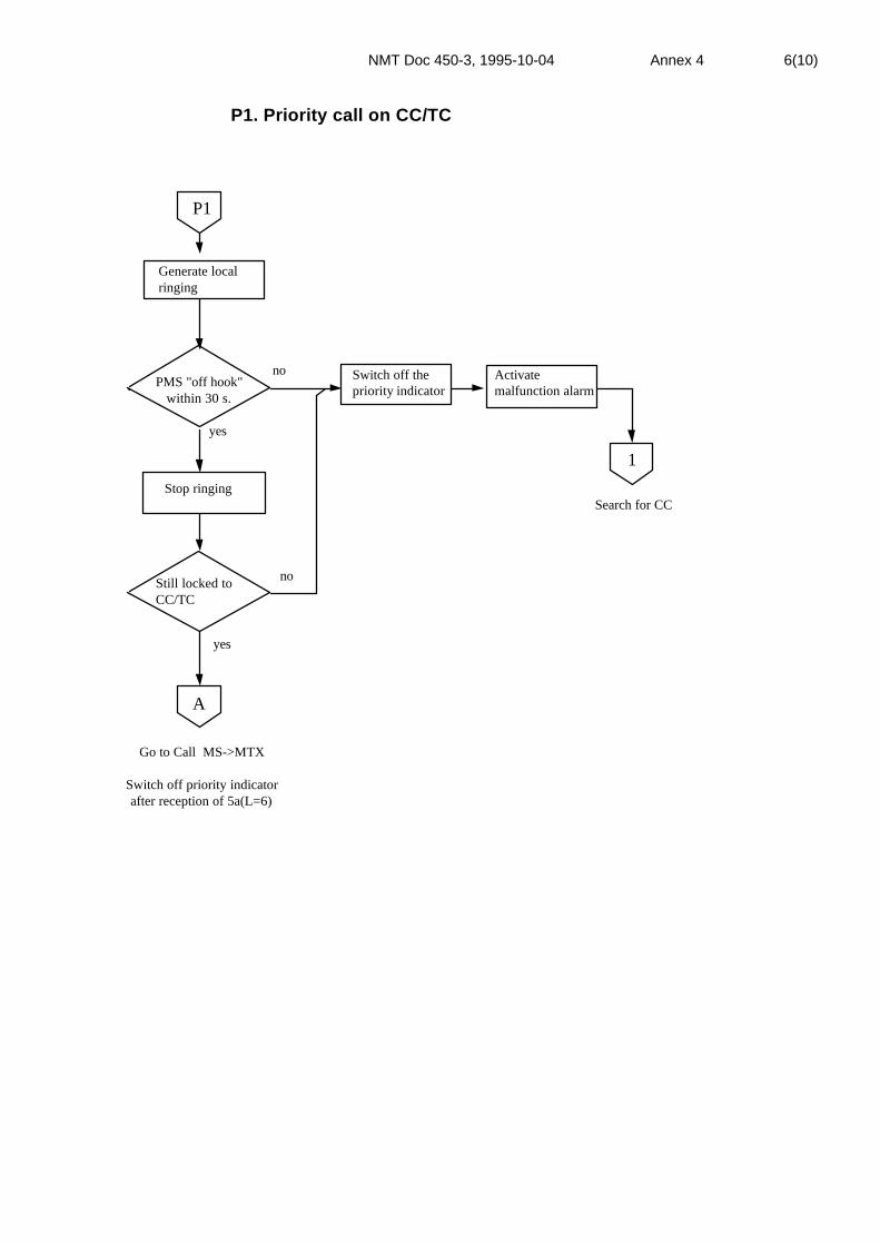
NMT Doc 450-3, 1995-10-04 Annex 4 6(10)
P1. Priority call on CC/TC
Generate localringing
PMS "off hook" within 30 s.
no
yes
P1
Still locked toCC/TC
no
yes
Switch off thepriority indicator
A
Go to Call MS->MTX
Switch off priority indicatorafter reception of 5a(L=6)
Search for CCStop ringing
Activatemalfunction alarm
1
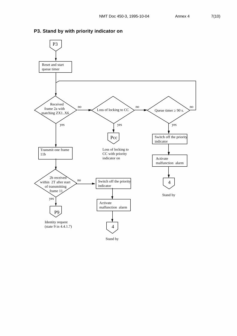
NMT Doc 450-3, 1995-10-04 Annex 4 7(10)
P3. Stand by with priority indicator on
Received frame 2a withmatching ZX1..X6
no
Transmit one frame11b
yes
2b received within 2T after start of transmitting frame 11
P9
Identity request(state 9 in 4.4.1.7)
no
P3
Loss of locking to CC Queue timer ≥ 90 s.no no
Pcc Switch off the priorityindicator
4Switch off the priorityindicator
4
Stand by
Activatemalfunction alarm
Stand by
Reset and startqueue timer
yes yes yes
Loss of locking toCC with priorityindicator on Activate
malfunction alarm

NMT Doc 450-3, 1995-10-04 Annex 4 8(10)
Pcc. Search for CC with priority indicator on
MS "off hook"
no
Pcc
Switch off the priorityindicator 6
Search for TCMS off hook
Additional rquirements for the Pcc sequence:
This sequence is overruled also if the queuetimer is exeded. The PMS shall then switch offthe priority indicator, activate malfunction alarmand enter state 3, Search for CC.
yes
3
6
Roaming
no
Switch off the priorityindicator 6
Search for TCroaming flag set,MS on hook
yes5Activate
malfunction alarm
6 Continue in flowchart Priority callyes
CC accepted Pccfound
Search for CC
no
fig. 5.3

NMT Doc 450-3, 1995-10-04 Annex 4 9(10)
P9. Priority call, identity check
no
yes
no
yes
no
yesno
yes
P9
Received 3bwithin T'
First attempt Lock to old CC
Received 2bwithin 2T
Switch off thepriority indicator
1
1
Search for CC
Transmit 4 frames 10b
Received first5a(L=9) within T afterstart of transmitting 10b
Generate local ringingMS clearing
PMS off hookbefore first ringingorder, 5a(L=9)
Activate malfunctionalarm
yes
no
P11a
Search for CC
Authenticationrequest (state11a in 4.4.1.7)
Go to allocatedtraffic channel
PMS on hook
Switch off the priorityindicator
Activatemalfunction alarm
2

NMT Doc 450-3, 1995-10-04 Annex 4 10(10)
P11a. Priority call, authentication request
Received 7 within T' afterreception of 5a(L=9)
yes no
PMS "off hook"
Transmit 4 frames13a(L=14)
Transmit 2 frames 15continuously
Received5a(L=9)within 30 s.
Switch off thepriority indicator
Generate ringingsignal in MS
yes
Received5a(L=3/11) within T after
start off transmitting frames 15
A
2MS clearing
Continue in flowchart A(in state Wait for Proceed to Send)
Call MS->MTX
yes
yes
no
no
P11a
Received5a(L=9)within 30 s.
Generate ringingsignal in MS
yes
no
PMS "off hook"
Transmit 4 frames13a(L=4)
Transmit 1frame 15
Transmit 2 frames 16followed by frames 15continuously
yes
no no
Activatemalfunction alarm
Switch off thepriority indicator
2
MS clearing
Activatemalfunction alarm
Switch off the priority indicatorafter reception of 5a(L=6)

NMT Doc 450-3, 1995-10-04 Annex 5 1(6)
ANNEX 5
SPECIFICATION FOR MOBILE PAY-PHONES INNMT-450 AND NMT-900
1. Definition
The complete specification for the NMT mobile pay-phone consists of therequirements stated in NMT Doc 450-1 and NMT Doc 450-3 for NMT-450,and NMT Doc 900-1 and NMT Doc 900-3 for NMT-900, including therespective Addenda, and the requirements set out in this document. Themobile pay-phone specified in this document shall use the specific "coin-box" signalling procedure for outgoing calls.
This specification states the requirements set for a mobile pay-phone fromthe NMT system point of view. The type approval authorities may also haveadditional national requirements for mobile pay-phones and may also defineother types of mobile stations as mobile pay-phones.
2. Types of mobile pay-phones
Different types of mobile pay-phones are foreseen. They may be divided intotwo groups:
- Coin-box mobile stations where the user pays for the call in connectionwith the conversation, either by means of coins or a debit/credit card.
- Call-meter mobile stations where the user pays the owner on the basis of acounter (call-meter) in the MS which registers the costs of the calls.
The mobile pay-phone is marked in the mobile telephone exchange (MTX)with a coinbox category which includes the transfer of tariff information tothe MS (NMT Doc 450-1 and NMT Doc 900-1, paragraph 4.4.1.6).
3. Charging information from MTX
Based on the dialled telephone number (or procedure) sent by the pay-phoneMS, the MTX decides the charging rate for the actual call. This tariffinformation Q1Q2 is sent from the MTX to the mobile pay-phone when thecharging is to start (frame 5b, "Answer to coinbox").
The tariff information indicates either a fixed rate (Table 1) or a timedependent rate (Table 2) for a special call, depending on the type of call (e.g.call to special services or long distance calls respectively).

NMT Doc 450-3, 1995-10-04 Annex 5 2(6)
The correspondence between the tariff information Q1Q2 received from theMTX and the actual charging rate is stored locally in the mobile pay-phone,and is given in Tables 1 and 2. Coding of the Q1Q2 values shall for bothNMT-450 and NMT-900 be made in accordance with paragraph 4.3.3.1 inNMT Doc 900-1.
The price for the call must be calculated locally in the mobile pay-phonebased on the received tariff information (Q1Q2 value).
The tariff information given by the MTX is not accurate, and may be up to 3% above the actual charging rate for time-dependent rates. For calls withfixed rates the given tariff information is adjusted upwards.
The charging rate is given in the monetary unit of the actual country.
The meaning of the Q1Q2 values shown in Tables 1 and 2 may be changed inthe future. It should therefore be easy to change the content in the tables.
4. Charging principles in different Nordic countries
Due to different tariff structures in the different countries, the charging rategiven to the mobile pay-phones will not always be 100 % correct. The callmay e.g. be charged at a per minute rate from the operator, while the tariffinformation from MTX to the mobile pay-phone will indicate a per secondrate.
The difference between the call charging by the operator and the tariffinformation given from the MTX to the mobile pay-phone must be taken intoaccount by the owner of mobile pay-phones.
It should also be taken into account that the operator may charge an initialfee for every call from a mobile pay-phone. Information regarding suchinitial fee will not be given in the Q1Q2 information.
5. Type approval of mobile pay-phones
A mobile pay-phone must be type approved by the type approval authoritiesbefore entering the NMT system. The type approval will include both thefunctioning as a normal MS and those special facilities (signalling, handlingof charging information etc.) which are connected with the pay-phoneservice.
The type approval will also include the interface between the MS and theconnected equipment.
6. Additional national requirements
The type approval authorities may add further requirements to thisspecification and to the user interface.

NMT Doc 450-3, 1995-10-04 Annex 5 3(6)
TARIFF INFORMATION Q1Q2 TO NMT PAY-PHONES
Table 1
The tariff information Q1Q2 gives the price per call and the price is given inthe local currency (DKK, FIM, NOK or SEK).
Table Q1Q2 (with decimal presentation) (frame 5b,13b)
Q1Q2 Currency Note00 ––– not used01 0,25 price/call02 0,50 - " -03 0,75 - " -04 1,00 - " -05 1,25 - " -
06 1,50 - " -07 1,75 - " -08 2,00 - " -09 2,50 - " -10 3,00 - " -
11 4,00 - " -12 5,00 - " -13 7,50 - " -14 10,00 - " -15 12,50 - " -
16 15,00 - " -17 17,50 - " -18 20,00 - " -19 25,00 - " -20 0,00 free
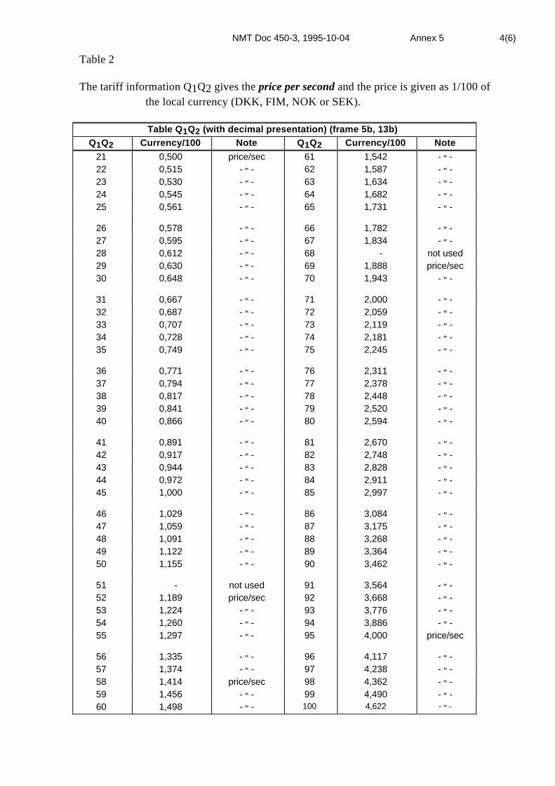
NMT Doc 450-3, 1995-10-04 Annex 5 4(6)
Table 2
The tariff information Q1Q2 gives the price per second and the price is given as 1/100 ofthe local currency (DKK, FIM, NOK or SEK).
Table Q1Q2 (with decimal presentation) (frame 5b, 13b)Q1Q2 Currency/100 Note Q1Q2 Currency/100 Note
21 0,500 price/sec 61 1,542 - " -22 0,515 - " - 62 1,587 - " -23 0,530 - " - 63 1,634 - " -24 0,545 - " - 64 1,682 - " -25 0,561 - " - 65 1,731 - " -
26 0,578 - " - 66 1,782 - " -27 0,595 - " - 67 1,834 - " -28 0,612 - " - 68 - not used29 0,630 - " - 69 1,888 price/sec30 0,648 - " - 70 1,943 - " -
31 0,667 - " - 71 2,000 - " -32 0,687 - " - 72 2,059 - " -33 0,707 - " - 73 2,119 - " -34 0,728 - " - 74 2,181 - " -35 0,749 - " - 75 2,245 - " -
36 0,771 - " - 76 2,311 - " -37 0,794 - " - 77 2,378 - " -38 0,817 - " - 78 2,448 - " -39 0,841 - " - 79 2,520 - " -40 0,866 - " - 80 2,594 - " -
41 0,891 - " - 81 2,670 - " -42 0,917 - " - 82 2,748 - " -43 0,944 - " - 83 2,828 - " -44 0,972 - " - 84 2,911 - " -45 1,000 - " - 85 2,997 - " -
46 1,029 - " - 86 3,084 - " -47 1,059 - " - 87 3,175 - " -48 1,091 - " - 88 3,268 - " -49 1,122 - " - 89 3,364 - " -50 1,155 - " - 90 3,462 - " -
51 - not used 91 3,564 - " -52 1,189 price/sec 92 3,668 - " -53 1,224 - " - 93 3,776 - " -54 1,260 - " - 94 3,886 - " -55 1,297 - " - 95 4,000 price/sec
56 1,335 - " - 96 4,117 - " -57 1,374 - " - 97 4,238 - " -58 1,414 price/sec 98 4,362 - " -59 1,456 - " - 99 4,490 - " -60 1,498 - " - 100 4,622 - " -

NMT Doc 450-3, 1995-10-04 Annex 5 5(6)
Table Q1Q2 (with decimal presentation) (frame 5b, 13b)Q1Q2 Currency/100 Note Q1Q2 Currency/100 Note101 4,757 - " - 146 16,95 - " -
102 - not used 147 17,45 - " -103 4,896 price/sec 148 17,96 - " -104 5,040 - " - 149 18,49 - " -105 5,187 - " - 150 19,03 - " -
106 5,339 - " - 151 19,59 - " -107 5,496 - " - 152 20,16 - " -108 5,657 - " - 153 - not used109 5,823 - " - 154 20,75 price/sec110 5,993 - " - 155 21,36 - " -
111 6,169 - " - 156 21,98 - " -112 6,350 - " - 157 22,63 - " -113 6,536 - " - 158 23,29 - " -114 6,727 - " - 159 23,97 - " -115 6,924 - " - 160 24,68 - " -
116 7,127 - " - 161 25,40 - " -117 7,336 - " - 162 26,14 - " -118 7,551 - " - 163 26,91 - " -119 7,772 - " - 164 27,70 - " -120 8,000 - " - 165 28,51 - " -
121 8,235 - " - 166 29,35 - " -122 8,476 - " - 167 30,21 - " -123 8,724 - " - 168 31,09 - " -124 8,980 - " - 169 32,00 - " -125 9,243 - " - 170 - not used
126 9,514 - " - 171 32,94 price/sec127 9,793 - " - 172 33,90 - " -128 10,08 - " - 173 34,90 - " -129 10,37 - " - 174 35,92 - " -130 10,68 - " - 175 36,97 - " -
131 10,99 - " - 176 38,06 - " -132 11,31 - " - 177 39,17 - " -133 11,65 - " - 178 40,32 - " -134 11,99 - " - 179 41,50 - " -135 12,34 - " - 180 42,72 - " -
136 12,70 - " - 181 43,97 - " -137 13,07 - " - 182 45,26 - " -138 13,45 - " - 183 46,58 - " -139 13,85 - " - 184 47,95 - " -140 14,25 - " - 185 49,35 - " -
141 14,67 - " - 186 50,80 - " -142 15,10 - " - 187 52,29 - " -143 15,54 price/sec 188 53,82 - " -144 16,00 - " - 189 55,40 - " -145 16,47 - " - 190 57,02 - " -

NMT Doc 450-3, 1995-10-04 Annex 5 6(6)
Table Q1Q2 (with decimal presentation) (frame 5b, 13b)Q1Q2 Currency/100 Note Q1Q2 Currency/100 Note191 58,69 price/sec 221 - not used192 60,41 - " - 222 139,6 price/sec193 62,18 - " - 223 143,7 - " -194 64,00 - " - 224 147,9 - " -195 65,88 - " - 225 152,2 - " -
196 67,81 - " - 226 156,7 - " -197 69,80 - " - 227 161,3 - " -198 71,84 - " - 228 166,0 - " -199 73,95 - " - 229 170,9 - " -200 76,11 - " - 230 175,9 - " -
201 78,34 - " - 231 181,0 - " -202 80,64 - " - 232 186,3 - " -203 83,00 - " - 233 191,8 - " -204 85,43 - " - 234 197,4 - " -205 87,94 - " - 235 203,2 - " -
206 90,51 - " - 236 209,2 - " -207 93,17 - " - 237 215,3 - " -208 95,90 - " - 238 221,6 - " -209 98,71 - " - 239 228,1 - " -210 101,6 - " - 240 234,8 - " -
211 104,6 - " - 241 241,6 - " -212 107,6 - " - 242 248,7 - " -213 110,8 - " - 243 256,0 - " -214 114,0 - " - 244 spare215 117,4 - " - - -
216 120,8 - " - - -217 124,4 - " - - -218 128,0 - " - 254 spare219 131,8 - " - 255 – not used220 135,6 - " -
Note 1: The notation "Not used" indicates that this Q1Q2 value never will be used totransfer tariff information, because frames with this content shall be handledas a normal line signal from the MTX.
Note 2; Currency value for (Q1Q2)N = 1,0293025 x currency value for (Q1Q2)N-1.Remember however "Not used" Q1Q2 values.
NMT Doc 450-3, 1995-10-04 Annex 6 1(4)
ANNEX 6
MOBILE STATION WITH MFT FUNCTION
Specification for data transmission from push-button set in MS using theMFT function (option)
1 Basic procedure
A mobile station equipment with MFT signalling facility shall be providedwith an MFT converter IN/OUT functionality.
The activation of this function in conversation state shall initiatetransmission of the signals "MFT converter IN/OUT". Furthermore a visualindicator in connection with the MFT function shall be provided, indicatingthat the MS is in MFT converter state.
A scrolling dialled digits display is mandatory.
Pressing a digit button in MFT converter state shall provide transmission oftwo consecutive digit frames (14a/b). The digit is immediately shown on thedialled digits display. MS shall accept and store several digits and transmitthem in the chosen order.
Pressing a digit button continuously, must not cause the same digit to beretransmitted.
When the MFT converter state is abandoned, i.e. MFT indicator switchedoff, the dialled digits display is cleared.
If the call is cleared during MFT state, the MFT converter in the MTX shallbe disconnected.
The flow chart for this function is given in Fig. 1 and the correspondingsignalling scheme is given in NMT Doc 450-1.

NMT Doc 450-3, 1995-10-04 Annex 6 2(4)
Conversation state
MFT-conv.IN activated
?
DDMempty
?
A BTransmit 4 frames 13a(L=8)
Received5a (L=4)
?
Transmit idle frames 15continuously (min. 2 frames)
MFT-indicator ON
Prevent disconnection ofsupervisory signal loop whentransmitting 1200 Baud
Set MFT OUT flag
Transmit 4 frames 13a (L=7)Yes
No
Yes
No
Yes
No
Yes
Yes
MFT-conv.OUT activated
?
No
Received5a (L=10)
?
MFTOUT flag
set?
Clear dialled digit displayand block push button set
Received5a (L=10) withinT' after transmit
13a?
No
Yes
Transmit 4 frames 13a (L=7)
Stop transmitting idle frames
MFT-indicator OFF
Set supervisory signal loopin normal condition
Clear dialled digit displayand MFT OUT flag
Conversation state
Digitsselected on push
button set?
Transmit digit, 2 frames 14a/b
Transmit idle frames15 continuously
Continue transmittingidle frames 15
No
No
No
Yes
Yes
Only needed if theoptional MFT procedureis implementedNote 2: When MFT converter IN/OUT button is
pressed (activated) and MFT indicatoris off, four frames 13a (L=8) shall besent, and when MFT indicator is on, fourframes 13a (L=7) shall be sent.Repeated activation of the MFT buttonshall initiate repeated transmission ofthe respective frames to MTX, which willacknowledge with appropriate frames.
DDM = Dialled digits memoryNote 3:
MTF-converter stateThis sequence is overruled by fixed clearing,MS on hook and autonomous time-out. In theclearing sequence MFT- indicator OFF shallbe included, and dialled digits memory andMFT OUT flag cleared.
Note 1: TT
==
1107 ms (8 frames)553 ms (4 frames)'
Fig. 1
NMT Doc 450-3, 1995-10-04 Annex 6 3(4)
2 Optional procedures
The following specification may optionally be used in combination with the"Specification for data transmission from the push-button set in MS".
If dialled digits memory and display contain information and MFT indicatoris off, activating the MFT function in conversation state shall initiatetransmission of the signal "MFT converter IN", the content of dialled digitsmemory is transmitted, followed by the "MFT converter OUT" signalling.
When the MFT state is abandoned, i.e. MFT indicator switched off, thedialled digits memory and display are cleared.
The flow chart for this function is given in fig. 2 and the correspondingsignalling scheme is given in NMT Doc 450-1.
Note: Automatic invocation of the MFT converter IN/OUT function, e.g. viaaddressing it from a memory location, is allowed as long as the manualoperation is still possible.

NMT Doc 450-3, 1995-10-04 Annex 6 4(4)
Transmit 4 frames 13a(L=8)
Received5a (L=4)
?
MFT-indicator ON
Prevent disconnection ofsupervisory signal loop whentransmitting 1200 Baud
Transmit digit, 2 frames 14a/b
DDMempty
?
Received5a (L=10)
?
Transmit idle frames 15(4 frames)
Received5a (L=10) withinT' after transmit
13a
Transmit 4 frames 13a(L=7)
MFTconverter out
activated?
Transmit 4 frames 13a(L=7)
Deblock push-button set
MFT-indicator OFF
Set supervisory signal loopin normal position
Deblock push-button set
Conversation state
A
Block push-button set
?
Clear dialled digit display
Clear dialled digits display
B
Page (2)
no
no
no
no
no
yes
yes
yes
yes
yes
Page (2)
Optional use of MFT converterThis sequence is overruled by fixed clearing, MS on hookand autonomous time-out. In the clearing sequence MFTindicator OFF shall be included, and dialled digits memoryand MFT OUT flag cleared.
Note 1: TT '
==
1107 ms (8 frames)553 ms (4 frames)
When MFT converter IN/OUT button is pressed(activated) and MFT indicator is off, four frames13a(L=8) shall be sent, and when MFT indicator ison, four frames 13a(L=7) shall be sent. Repeatedactivation of the MFT button shall initiate repeatedtransmission of the respective frames to MTX,which will acknowledge with appropriate frames.
Note 2:
Fig 2

NMT Doc 450-3, 1995-10-04 Annex 7 1(7)
ANNEX 7
MOBILE STATION WITH INTERFACE FOREXTERNAL EQUIPMENT
This annex specifies how external equipment, type approved for use in theNordic telephone network, shall be connected to a mobile station in theNMT system. Connection of external equipment to an MS is subject tonational (local) regulations.
1. Connection of external equipment for data transmission, telematic services,slow scan television etc. can be done in two ways:
i) The equipment is connected to the MS via a separate interface unit.
ii) The external equipment is integrated with the MS.
In addition to the specifications given in NMT Doc 450-1 and NMT Doc450-3, the following shall apply.
Note: In order to distinguish between normal telephone operation of theMS and operation with an external equipment, the term data mode isused to indicate the latter.
2. The external equipment is connected to the MS via a separate interface unit.
This unit should preferably be made such that it can be connected to alreadytype approved mobile stations.
2.1 The interface is shown in Figure 1:
Externalequipment
Interface unit MS
Figure 1. Interface between the external equipment and the MS.
The combination interface-mobile station shall fulfil the frequency responserequirements specified for the mobile station in NMT Doc 450-3 Chapter 2and 3, paragraph 2.2.12 and 2.3.20 with following relief.
The frequency response tolerances between 300 Hz and 3400 Hz shall be 1dB wider. See. fig. 2 and fig. 3.
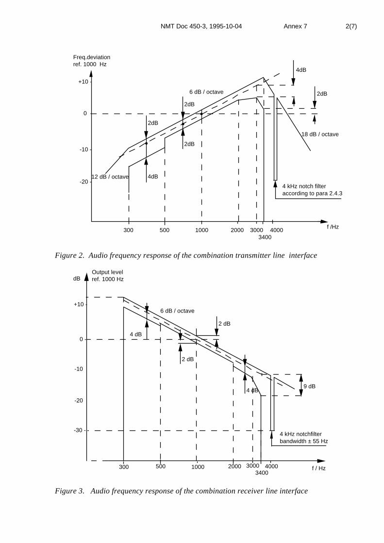
NMT Doc 450-3, 1995-10-04 Annex 7 2(7)
4dB
2dB
4dB
2dB
2dB
2dB
4 kHz notch filteraccording to para 2.4.3
18 dB / octave
12 dB / octave
6 dB / octave
Freq.deviationref. 1000 Hz
+10 -
0 -
-10 -
-20 -
300 500 1000 2000 3000 40003400
f /Hz
••
•
Figure 2. Audio frequency response of the combination transmitter line interface
-30 -
0 -
-10
-20
+10 -
dBOutput levelref. 1000 Hz
300 500 1000 2000 3000 40003400
f / Hz
4 kHz notchfilterbandwidth ± 55 Hz
2 dB
4 dB
2 dB
4 dB
6 dB / octave
9 dB
Figure 3. Audio frequency response of the combination receiver line interface

NMT Doc 450-3, 1995-10-04 Annex 7 3(7)
2.1.1 2-wire connection
Figure 4 shows the levels which apply for connecting an external equipmentthrough a 4-wire/2-wire terminating set to a mobile station. It is assumedthat the terminating set has an attenuation of 3,5 dB. If a terminating setwith different attenuation is used, the levels indicated on the 2-wire side stillapply. In Finland, Norway and Sweden the terminating set shall have abalancing network consisting of a resistance of 860 ohm in parallel with a 39nF capacitor, see figure 5. In Denmark balancing impedance is 600 ohm.
The reflection attenuation (Ar) on the 2-wire side shall be ≥ 18 dB Ar re 860Ω//39 nF.
(In Denmark Ar re 600 Ω.)
Receive
An 1 kHz tone with a peak-to-peak deviation of ± 3 kHz shall result in alevel of -28 dBm ± 2 dB on the 2-wire side of the terminating set.If this corresponds to a level +R dBm at the output from the MS, anattenuator of (R+ 24,5) dB shall be inserted on the 4-wire side as shown infigure 5 (3,5 dB loss in the terminating set is assumed).
The power level is measured with an inserted load of 600 ohm.
Note: R > - 24,5 dB in order to avoid an additional amplifier.
Transmit
A 1 kHz tone at a level of -3 dBm ± 2dB applied on the 2-wire side of theterminating set shall result in a peak-to-peak deviation of± 3 kHz on the radio channel. If the deviation corresponds to -S dBm at theinput to the MS, an attenuator of (-6,5 + S) dB (assuming 3,5 dB loss in theterminating set) must be inserted on the 4-wire side of the terminating set.
The power level is measured with an inserted load of 600 ohm.
Note: S should be chosen such that S > 6,5 dB in order to avoid anadditional amplifier on the 4-wire side.

NMT Doc 450-3, 1995-10-04 Annex 7 4(7)
± 3 kHz
± 3 kHz
+ R dBm
MS
- S dBm
(R + 24,5) dB*
- 28 dBm±2dB
860 Ω/**39 nF
- 3 dBm±2dB
(-6,5 + S) dB*
Assuming 3,5 dB loss in both directions of transmission in the terminating set600 Ω in Denmark.
***I
Figure 4. Measuring levels for connecting a terminating set to a mobile station
Note: The output level from the external equipment is supposed to be -10dBm (i.e. 7 dB below the test-tone level) as is normally the case inome countries.
2.1.2 4-wire connection
Figure 5 shows the levels which apply for connecting a 4-wire terminatingequipment to the MS.
± 3 kHz
± 3 kHz
X dBm
MS
-Y dBm
from (X + 5) to(X + 25) dB -5 to - 25 dBm
860 Ω/**39 nF
+ 1 dBm(Y + 1) dB
Figure 5. Measuring levels for connecting a 4-wire equipment to amobile station

NMT Doc 450-3, 1995-10-04 Annex 7 5(7)
Receive
A 1 kHz tone with a peak-to-peak deviation of ±3 kHz shall result in a levelbetween -25 dBm and -5 dBm at the input of the external equipment. With acorresponding receive level of X dBm from the MS, an attenuator with theappropriate loss (between (X + 5) dB and (X + 25) dB) has to be inserted asshown in the figure 6.
The power level is measured with an inserted load of 600 ohm.
Note: The receive level X should be chosen such that the value of theattenuator is positive.
Transmit
A 1 kHz tone at a level of 1 dBm applied as shown in figure 5 shall result ina peak-to-peak deviation of ± 3 kHz. With a transmit level of -Y dBm anattenuator with loss Y + 1 dB has to be inserted as shown.
The power level is measured with an inserted load of 600 Ω.
Note: Y should be chosen such that Y > -1 dB in order to avoid anadditional amplifier.
Note: The output level from the external equipment is supposed to be -6dBm (i.e. 7 dB below the test-tone level) as is normally the case insome countries.
2.2 With external equipment the MS shall still be capable of detecting anysignalling from the MTX (e.g. forced release).
2.3 Normal telephone operation of the MS shall be disabled when the externalequipment is in the conversation phase. Switching between data mode andspeech mode may be done either manually or automatically.

NMT Doc 450-3, 1995-10-04 Annex 7 6(7)
2.4 Optional automatic operation of reception shall be as follows:
Some external equipment (e.g. facsimile and data modems) may be equippedwith an automatic call detection facility (circuit 125 in V24). This facilityrequires that the interface unit can simulate the calling function of thetelephone network.
For each "ringing order" from the MTX to the MS, the interface unit shallgenerate a 20-55 1) signal for a duration of 0,5 sec to 1 sec 2). The voltagemust be greater than 25 V r.m.s. 3) but less than 100 V r.m.s. The minimumimpedance of the loop is 7 kΩ.
2.4.1 The interface unit must be capable of detecting the off-hook condition fromthe external equipment. This would normally correspond to a drop in the DCloop resistance to less than 300 Ω (less than 400 Ω in Denmark and Finland).
The interface unit must be connected to the MS in such a way that the MScan initiate mobile clearing in the case the external equipment generates theon-hook condition.
2.4.2 The interface unit may include adaptation of dialling facility from an externalequipment, in conformity with the requirements for the national telephonenetwork.
2.5 Some equipment may require a DC line current of 25 mA in order to operate.
2.6 Any AC or DC voltages generated by the interface unit as defined abovemust be applied to the input or output of the MS.
2.7 Automatic equipment for transmitting may be specified by the manufacturer.
2.8 The circuit between the interface unit and the external equipment can beeither 2- or 4-wire. The connector types shall be approved by the typeapproval authority. Information about connector types is available uponrequest from the type approval authority/accredited test laboratory.
2.9 In data mode the audio output need not be muted after reception of framesynchronisation followed by six information bits of value zero.
-------------------------------------------------------------------------------------------------------------
1) In Denmark the interface unit shall generate either a 25 Hz ± 2,5 Hz signal or a 50 Hz ± 5 Hzsignal.
2) In Finland the duration shall be 1000 ms ± 150 ms.
3) In Denmark and Finland the voltage must be greater than 40 V r.m.s

NMT Doc 450-3, 1995-10-04 Annex 7 7(7)
2.10 To the 2-wire connector of the type approval interface unit, it is allowed toconnect without any additional type approvals following types of equipment,which have been type approved for the use in public switched telephonenetwork in the country where the MS is registered:
- modems
- telecopy equipment
- other type of data equipment including a modem type approved for use inthe public switching telephone network
- equipment for speech transmission
The output power for other signals than speech shall be lower than or equalto -10 dBm. The audio band modulation method shall not be similar to orcause interference to the NMT signalling system (FFSK). E.g. CCITTmodem V.23 should not be used due to regular detection of false frames atthe FFSK modem of the MTX.
Any other type of the external data equipment, e.g. equipment including anon standard modem, shall be type approved for the use in the NMT and thepublic switching telephone network.
3. External equipment integrated with the MS
The specifications given in section 2.1-2.9 shall still be met. A suitablemethod for automatic call detection may be determined by the manufacturer.
4. User Manual
The manufacturer shall provide a user manual together with the interfaceunit. The Administration reserves its right to comment on the manual.
5. Marking of the interface unit
The interface unit shall be marked in the same way as the MS.
6. Type approvals
The interface unit shall be type approved by the type approval authority.
The user manual shall be available when type approval is applied for.
Use of external equipment in other countries than the country in which theMS is registered, is subject to national regulations.

NMT Doc 450-3, 1995-10-04 Annex 8 1(3)
ANNEX 8 (OPTION)
1 SPECIFICATION FOR REGISTER RECALLFUNCTION
When implemented, all requirements shall be met.
Certain subscriber facilities which are activated during the call require aregister recall function ("R-button"). In conversation state (i.e. lastingfrom reception of frame 3b to clearing) this button may not be used forother functions. The R-function shall be accessible by a one-keyoperation in conversation state, i.e. it shall not be hidden under shiftmode or any other multi-key operation. In any other state this buttonmay be used for other functions.
Examples of these services invoked by register recall are:Hold for enquiry, conference service etc.
When the R-button is activated in conversation state, the MS transmitsa series of signalling frames to the MTX. The signalling frames areacknowledged from the MTX, and a dialling tone is sent. When theacknowledgement frames are detected by the MS, the dialled digitsmemory (DD.) shall be cleared.
The digits which then are selected on the push button set are transmittedto the MTX in a non-encrypted form if frame 5a(L=3) is received fromthe MTX, and in an encrypted form if frame 5a(L=11) and frame 7(including RAND) are received. If RAND is not received in the lattercase, MS clears the call.
When the first digit is received in the MTX, the dialling tone is stopped.
When a sufficient number of digits is received in the MTX, addresscomplete is sent to the MS.
The MS will then change to speech position and clear the display.When the received digit is analysed, the MTX will enter the selectedfacility or set up a connection to the dialled subscriber number.
If the subscriber presses a wrong digit button while using the registerrecall function, the R-button must be reactivated and the transmissionof digits restarted.
Note: Automatic invocation of the "R-functionality" , e.g. viaaddressing it from a memory location, is allowed as long as the manualoperation is still possible.

NMT Doc 450-3, 1995-10-04 Annex 8 2(3)
2 OPTIONAL PROCEDURE
If DDM and display contain information when the R-function isactivated in conversation state, the "register recall" frames shall be sentto the MTX. The frames are acknowledged and dialling tone is sent.When acknowledgement frames are detected by MS, the content inDDM shall be transmitted followed by idle frames.
When a sufficient number of digits is received in the MTX, addresscomplete is sent to the MS.
The MS will then change to speech position and clear the display. TheMTX then activates whatever is requested by the transmitted digits.
The flowchart for this function is given in Fig. 1, and the correspondingsignalling schemes are given in NMT Doc 450-1.

NMT Doc 450-3, 1995-10-04 Annex 8 3(3)
Register Recall function in MS
These sequences are overruled by fixed clearing, MS on hook and autonomous
ReceivedRAND
Received 5a(L=3/11) DDM not empty
Register recallbutton activated
Calculate newB-key
Transmit4 frames 15
Transmit 4frames 13a(L=5)
Transmit digitsin DDM:n x 2 frames14a/b*)followed by idleframescontinuously
Register recallbutton activated
Transmit 4frames 13a(L=5)
Transmit digits2 frames 14a/b*)
Push buttonset activated
Received address
complete 5a(L=6)
Stop transmissionof idle frames
Display clearedDialled digitsshown on display
*) Note: Encryption of digits takes place if 5a(L=11) has been received.
Conversationstate
Received5a(L=3/11)DDM empty
Dial tone receivedfrom MTX
Transmit idleframescontinuouly
Conversationstate
Conversationstate
Wait for buttonactivation oraddress complete
Conversationstate
Wait for buttonactivation oraddress complete
Conversationstate
Fig.1

NMT Doc 450-3, 1995-10-04 Annex 9 1(1)
ANNEX 9
MOBILE STATION FOR COMBINED USE (HMSWITH BOOSTER)
A Definition
Mobile station for combined use is a mobile station (MS), which contains adetachable unit in accordance with the definition for handheld mobile station(HMS) in Annex 3.
B Technical requirements
The detachable unit for use as handheld mobile station shall fulfil therequirements in Annex 3, paragraph B.
The mobile station for combined use shall unconditionally fulfil allrequirements for ordinary mobile stations (MS).

NMT Doc 450-3, 1995-10-04 Annex 11 1(2)
ANNEX 11
MOBILE STATION EQUIPPED WITH MORE THANONE HANDSET AND/OR CONTROL UNIT
1. Definition
An MS may be equipped with more than one handset and/or control unit(called HS in this Annex).
2. Technical requirements
2.1 More than one HS, used simultaneously
It is subject to national regulations whether to permit a speech path to beopened in more than one handset at a time.
2.2 Electrical or mechanical differences
If the additional HS is not electrically and mechanically identical to theoriginal one, but it requires the presence of the original HS, only thecompliance to the following requirements has to be tested:
NMT Doc 450-3 paragraphs:
- 2.6.5 Receive volume control- 2.6.8 Maximum sound level of handset earpiece- 2.7 Stability loss
If the original HS includes a limiter, amplifiers etc., the additional HS shallbe equipped with the same circuitry.
If it is possible to operate the MS with the original HS disconnected and theadditional HS is not electrically and mechanically identical to the originalone, full type approval tests shall be carried out.
If any call set-up devices are included in the HS e.g. keypad, all requirementsfor visual indicators have to be fulfilled.
2.3 Operation
The MS is regarded to be in "on-hook" state only if all HS are "on-hook".
The MS is regarded to be in "off-hook" state if any HS is "off-hook".
NMT Doc 450-3, 1995-10-04 Annex 11 2(2)
3. Formal requirements
3.1 Type approval
The additional HS and its associated equipment have to be submitted for typeapproval.
All requirements in Annex 1 and national requirements on measurementreports have to be fulfilled.

NMT Doc 450-3, 1995-10-04 Annex 12 1(2)
ANNEX 12
SPECIFICATION FOR A HANDHELD MOBILESTATION WITH BATTERY SAVING FUNCTION,BMS (OPTION)
1. Definition
A Battery saving Mobile Station (BMS) is defined as a Handheld MobileStation (HMS) as defined in Annex 3, acting according to NMT Doc 450-1paragraph 4.3.3.12 and the following requirements.
2. Technical requirements
Due to the nature of the battery saving function some special requirementshave to be fulfilled.
2.1 Battery Saving Orders (BSO)
After receiving the additional information H1(14), H2(11) and H7(addressing actual group according to NMT Doc 450-1 paragraph 4.3.3.12.3)the BMS may close down any desired functions (except the ones stated insection 2.6) for the time determined by H3 as stated in NMT Doc 450-1paragraph 4.3.3.12.4.
2.2 Wake up.
2.2.1 End of battery saving period
Immediately after the battery saving period has expired the BMS shall belocked to the same channel on which it was locked before the BSO.
The BMS must, according to the above, memorise the CC channel numberand keep an accurate timer running during the battery saving period.
After the battery saving period the BMS shall immediately be able to receiveany information on the channel indicated by the memorised CC channelnumber.
2.2.2 No calling channel present
If the memorised channel number after the sleeping period indicates anotherchannel type than a CC, the BMS shall immediately start searching for a newCC according to the normal procedures.

NMT Doc 450-3, 1995-10-04 Annex 12 2(2)
2.3 Loss of locking
Due to the nature of the battery saving function, the normal evaluation of thechannel quality is not possible. The following additional requirements shallapply to NMT Doc 450-3 paragraph 5.2.1.2 " Loss of locking....":
Subparagraph a) The RF-level measured in one awake period shall beregarded as lasting through the following sleepingperiod, i.e. the sleeping period shall be included in thetwo minute period.
Subparagraph b) Not affected
Subparagraph c) The sleeping period is logically equivalent to a correctframe.
2.4 Locking to a CC
After locking to a new CC the BMS shall ignore the first received BSO.
2.5 Unsuccessful call attempt or delayed channel order
After reception of frame 2a the BMS shall ignore the first received BSO.
2.6 Permanent functions
2.6.1 The display and visual indicators shall not be affected by the sleepingperiod. However, an extra indicator to display the battery savingperiods is permitted.
2.6.2 The BMS shall always be sensitive to any user initiated operation.
3. Enabling the battery saving function
The battery saving function shall be included in the type approvalmeasurements. It shall be noted in the application for type approval that themanufacturer wishes to have a type approval for the BMS function.
The battery saving function shall be enabled together with the setting of thesubscriber number and with the same security precautions.
The user shall not by any means be able to turn off the battery savingfunction.
The BMS must be operated with a BMS category in the MTX. If not so andthe BMS is operated in the system without BMS subscription, it will notfunction properly.

NMT Doc 450-3, 1995-10-04 Annex 15 1(1)
ANNEX 15
ELECTRICAL INTERFACE USED IN THE TYPETEST OF THE MS
This annex specifies an electrical interface to be used in the mobile stationsin type approval tests. If the indicators of the mobile station are difficult todetect using optical sensors, the MS delivered for type approval tests shall beequipped with an electrical interface.
1. Mechanical construction
The used connector shall be of a D-type, female and 25 pole mounted on theMS or on a cable from the MS.
2. Pin allocation
Pin Meaning Function1 Ground2 Control of DUT, bit 0 Power ON/OFF3 Control of DUT, bit 1 Hook switch ON/OFF4 Control of DUT, bit 2 Hook switch on handset5 Control of DUT, bit 3 Hands-Free ON/OFF6 Control of DUT, bit 47 Control of DUT, bit 58 Control of DUT, bit 69 Control of DUT, bit 7
Pins 10, 11, 12, 13 Not specified14 Data from DUT, bit 0 ON/OFF hook indication15 Data from DUT, bit 1 Power ON/OFF indicator16 Data from DUT, bit 2 Service indicator17 Data from DUT, bit 3 Call received indicator18 Data from DUT, bit 4 Roaming alarm indicator19 Data from DUT, bit 5 Ringing signal ON/OFF20 Data from DUT, bit 6 Malfunction alarm ON/OFF21 Data from DUT, bit 7 DDM empty/not empty
Pins 22, 23, 24, 25 Not specifiedDUT = Device Under Test
3. Electrical specifications
The interface uses standard CMOS logic. "5 V supply voltage levels". Highlevel indicates that the function is/should be activated in the MS. Low levelindicates that the function is/should be inactivated in the MS.

NMT Doc 450-3, 1995-10-04 Annex 16 1(3)
ANNEX 16
DESCRIPTION OF A RANDOM GENERATOR
As stated in Section 3, the 120 bit SAK has to be generated randomly, withthe exception of the most significant bits of K1, K2 and K3 which are set toone. In this Annex a possible method for generating the remaining 117 bitsof the SAK is described. It should be noted that there exist better randomgenerators than the one described below. However, they are more complexand probably not suitable for this application.
1. The linear congruential method
The generator for 120 bit integers is based on the well-known linearcongruential generator (LCG). A short description of this generator is givenhere. For more details see D.E. Knuth, The Art of Computer Programming,part 2: Seminumerical Algorithms (Addison-Wesley, Reading Mass., 1981).First of all the following four integers are chosen:
m > 0 : the modules of the sequence,
1< a < m : the multiplier of the sequence,
0 ≤ c < m : the increment of the sequence and
0 < X0 < m : the seed of the sequence.
The desired linear congruential sequence (Xn) of random numbers is thenobtained by setting
Xn : = (a* Xn-1 +c) mod m, n > 0 (1)
Because the elements of the sequence can only take values between 0 andm - 1, it is clear that after a certain value of n the sequence will repeat itself.This value of n is called the period of the sequence. The following propertyis of importance.
PROPERTY:
Let m be a prime and assume that c = 0, a > 1 and X0 > 0. Then the sequencegenerated by (1) will have period m – 1.
In this application the following sequence will be used:
Xn : = a* Xn-1 mod (2127 –1), n > 0, (2)
where a and X0 are chosen randomly.

NMT Doc 450-3, 1995-10-04 Annex 16 2(3)
By the property above this sequence will have a period 2127 –2, which isabout 1.7* 1038 , because 2127 –1 is a prime. Also it should be noted thatarithmetic modulo 2127 –1 is very easy. Let Y be the result of the integermultiplication a* Xn-1 . Clearly Y will consist of at most 254 bits and thus itcan be written as
Y=Y1 + 2127* Y2 , 0 ≤ Y1 , Y2 < 2127 (3)
Because 2127 mod (2127 –1) = 1, it follows from (2) and (3) that
Xn = (Y1 +Y2 ) mod (2127 –1) (4)
which is easy to compute.
2. A random generator for 117-bit integers
As stated above, the generator will use the linear congruence sequence.(Xn )defined by (2). The sequence (Xn ) consists of 127-bit integers. To reducethese integers to 117-bit integers the following functions will be needed.
Let 0 ≤ u < 15 be an integer. A 127-bit integer is written as
X = X0 + X1* 256 + X2* 2562 + .....+ X15* 25615 , (5)
where 0 ≤ Xi < 256, i=0, 1...15 are the bytes of X (note that X15 is less than128). The function fu maps X onto the 117-bit integer that is obtained bydeleting the u-th byte of X and the 2 most significant bits of X. The functiongu maps X onto the 10 bit integer obtained by concatenating the u-th byte ofX and the 2 most significant bits of X. More precisely,
fu(X) : = X0 + X1* 256 + .. + Xu–1* 256u–1 + Xu+1* 256u
+ Xu+2* 256u+1 + .. +X14* 25613 + (X15 mod 32)*25614
gu(X) : = Xu + (X15 div 32)* 256
Now let N be the number of keys to be generated and let k, r and s be fixedintegers. The random 117-bit integers Zn (n=1, 2, ...,N) are computed asfollows.
INITIALISATION
1. Choose randomly the following integers:
0 ≤ j < k, 0 ≤ u < 15, 2126 ≤ a < 2127 –1 and 1 < X0 < 2127 –1.

NMT Doc 450-3, 1995-10-04 Annex 16 3(3)
2. Make a table V[0...k–1] by defining
V[0]: = X0 ;
V[i]: = Xi = a* Xi–1 mod (2127 ), 0 < i < k
STEP FOR n = –(s–1), –(s–2), ..., 0, 1, ..., N
1. Let Y: = V(j) and compute
Xn+k+s–1 : = a* Xn+k+s–2 mod (2127 –1)
2. Put V(j): = Xn+k+s–1
Zn : = fu(Y)
j: = (k* gu(Y) ) div 210
3. If (n–s) mod r = 0 then generate a new integer 0 ≤ u < 15.
The steps for n = –(s–1), –(s–2), ..., 0 can be seen as part of the initialisationprocedure. The parameter k should be odd and of order 100, for examplek = 99 is a good choice. The parameter can be taken as s = 3k. The integer u,0 ≤ u < 15 is changed after r steps. It is advisable to take r reasonably smallsay r = 10 significant bits of the fraction in milliseconds of the system timeof the computer system when a new u has to be generated. The new u is thendefined as u: = (15* f) div 64.
The starting values j, a and X0 should be changed regularly, for exampleonce every three months. A way to generate these values using the systemtime of the computer system is explained below.
Type the alphabet twice on a terminal and record each time a key is strickenthe fraction in milliseconds of the system time. By taking the 6 leastsignificant bits of these fractions one obtains 52 random numbers d0 ,d1,...,d51 , with 0 ≤ di < 64. We can then define
a: = d0 + d1* 64 + ... + d20* 6420 + 2126 ,
X0 : = d21 + d22* 64 + ... + d41* 6420 + (d42 mod 2)* 2126
j: = (k* d43 ) div 64.
Note that these values must satisfy the conditions stated in block 1 of theinitialisation above. If one or more of these values do not satisfy theseconditions one can generate new values the same way as described above.Also, one has to check whether the SAKs obtained this way satisfy theconditions of Section 3.

NMT Doc 450-3, 1995-10-04 Annex 17 1(6)
ANNEX 17
SPECIFICATION FOR A COMBINED NMT-450/900MOBILE STATION (CMS)
1 Definition
A combined NMT-450/900 mobile station (CMS) is a car-mounted MS,portable MS or a hand portable MS which can be operated in both NMT-900and NMT-450 networks. The switching between the networks is automaticwith a preference for NMT-900 network. It shall fulfil the requirementsstated for NMT-450 mobile stations when functioning in 450 mode and thosefor NMT-900 mobile stations when in 900 mode. In addition, therequirements and exceptions listed in this annex shall be fulfilled. A CMShas two identities: one for NMT-900 and one for NMT-450.
2. Switching between NMT-450 and NMT-900 networks
The MTXH for a CMS is normally an MTX of an NMT-900 network. It isalso possible that the CMS is registered in an NMT-450 MTX but in bothcases, operation in the NMT-900 network is preferred when this is available.To prevent frequent roaming and switching between the networks, specialchannel acceptance criteria are used as defined below. See also Figure 2.
The CMS shall always, also during power off, maintain information on thevalid traffic area (Y2) for both systems separately and the previously selectedmode (NMT 450 or NMT 900).
2.1 Operation after switching on power
When the power is switched on, the CMS shall test for NMT-900 as follows.
Definition:
Test for NMT-900: The CMS scans the NMT-900 basic channel band twiceusing RF level criterion C (full sensitivity) according to NMT Doc 900-3,paragraph 5.2.1.4.1. If an FFSK signal is detected the CMS shall check ifthere is a match between the received channel number and the synthesisersetting, as well as between the country code received and the stored Y1. Ifthis is the case the CMS shall stop scanning and the test is considered assuccessful.
After a successful test for NMT-900, the CMS shall enter the 900 mode.

NMT Doc 450-3, 1995-10-04 Annex 17 2(6)
Definition:
Entering 900 mode: After a successful test for NMT-900 the CMS shall enterthe 900 mode in the same way as "power on" after "off condition" is definedin NMT Doc 900-3 paragraph 5.3.1, state 1.1. The MS shall use the identitywhich it has for the NMT-900 system.
If after two scans, the CMS has not been able to enter the 900 mode (test forNMT-900 unsuccessful), it shall test for NMT-450.
Definition:
Test for NMT-450: The CMS scans twice the NMT-450 band using fullsensitivity (NMT Doc 450-3, paragraph 5.2.3.3). Whenever FFSK is detectedand a match is obtained between the channel number and the synthesizersetting, as well as between the received country code and the stored Y1, thetest is considered as successful.
If the test for NMT-450 was successful the CMS shall enter the 450 mode.
Definition:
Entering 450 mode: After a successful test for NMT-450 the CMS shall enterthe 450 mode in the same way as "power on" is defined in NMT Doc 450-3,paragraph 5.3.2, state 1. The MS shall use the identity which it has for theNMT-450 system.
If after the two scans in the NMT-450 band mentioned above, the CMS hasnot been able to enter the 450 mode (test for NMT-450 unsuccessful) it shalltest for NMT-900 again starting the procedure described in this paragraphfrom the beginning.
If a hook-off is made during a test sequence the CMS shall return to themode (450 or 900) which was previously entered.
2.2 Switching from NMT-900 into NMT-450
The CMS can switch into NMT-450 network only outside NMT-900coverage area or if no NMT-900 signalling can be received.
2.2.1 Loss of NMT-900 reception during stand by
When the CMS has lost locking to a calling channel and no CC has beenreceived in one complete searching procedure, i.e. 1 times 15 scans, it shalltest for NMT-450 as defined in 2.1. If this is successful it shall enter the 450mode. If this is unsuccessful it shall enter the 900 mode (see 2.1).

NMT Doc 450-3, 1995-10-04 Annex 17 3(6)
2.3 Switching from NMT-450 into NMT-900
The CMS can switch from NMT-450 into NMT-900 in four cases:
2.3.1 After a call
After every clearing sequence after a conversation state in 450 mode, a testfor NMT-900 is made. If this is successful the CMS shall enter the 900 mode(see 2.1). If not successful, it shall enter stand-by state on the previous CC in450 mode.
2.3.2 Manual switching
When a hook-off is made during stand-by in the 450 mode and the dialleddigits memory is empty, the CMS shall test for NMT-900. If the test issuccessful it shall enter the 900 mode.
If the test is unsuccessful the CMS shall enter stand-by state on the previousCC in the 450 mode. However, if the roaming alarm indicator was on whenthe hook-off was made, the CMS shall store the CC number and go to arandom channel to search for a TC for manual roaming (scheme A) as statedin NMT Doc 450-3.
2.3.3 No channel order received
The CMS shall test for NMT-900 if it has received its identity in frame 2atwice without receiving frame 2b during 10 seconds (±1 s) after the firstreceived frame 2a. If the test is successful it shall enter the 900 mode. If not,the CMS shall enter state search for CC (450 mode).
2.3.4 After power-on
This is described in paragraph 2.1 above.
2.3.5 Timer control
In the 450 mode, an additional timer is provided. Controlled by this, the MSshall test for NMT-900 every 4 minutes (±20 s) while in stand-by state. If thetest is successful it shall enter the 900 mode.
2.4 Switching from NMT-450 into NMT-900, Alternative to 2.3
The CMS shall initiate a test for NMT-900 at least every 2 minutes. The testshall be performed continuously or initiated by a timer.
When testing for NMT-900, the CMS shall continue to be active in NMT-450 mode. If the test is successful the CMS shall switch to NMT-900 modeif the CMS is in stand-by state or in search for CC state. If the CMS is inany other state it shall remain in NMT-450 mode.

NMT Doc 450-3, 1995-10-04 Annex 17 4(6)
3. User interface
The user interface of the CMS shall fulfil the requirements for NMT-900mobile stations as described in NMT Doc 900-3, paragraphs 3 and 4, takinginto account the following notes:
Paragraph 3.8. The values of Y1 mentioned are valid for NMT-900 only.See NMT Doc 450-3 for Y1 values for NMT-450.
An extra indicator is required for displaying the present mode of the CMS.The recommended symbols for the 450 mode is 450 and for 900 mode 900,so that there is no confusion between the dialled digits and this indication.During the test for NMT-900 and test for NMT-450, the correspondingsymbol shall be on and it shall be flashing.
4. Transmitter power
The overall transmitter power levels for different types of CMSís are thefollowing.
Power bits MS HMS
NMT-450 *)
11 PH = 15 /7 W ± 1.5 dB PH = 1.5 W ± 2.0 dB
10 PM = 15 W - (10 ± 3) dB PM = 1.5 W ± 2.0 dB
01 PL = 15 W - (20 ± 3) dB PL = 1.5 W - (10 ± 3) dB
00 PL = 15 W - (20 ± 3) dB PL = 1.5 W - (10 ± 3) dB
NMT-900 *)
11 PH = 6 W ± 2 dB PH = 1 W ± 3dB
10 PH = 6 W ± 2 dB PH = 1 W ± 3 dB
01 PM = 6 W - (8 ± 3) dB PM = 1 W ± 3 dB
00 PL = 6 W - (18 ± 3) dB PL = 1 W - (10 ± 3) dB
*) For a portable CMS, the output power can be selected as specified inNMT Doc 450-3, Annex 2 and NMT Doc 900-3, Annex 2.

NMT Doc 450-3, 1995-10-04 Annex 17 5(6)
5. Additional requirements
It shall be possible to disable the 450 mode for each country selector positionseparately by similar routines as used for programming the subscriberidentity. This means that in preselected countries, the CMS shall operate inNMT-900 mode only.
It may be possible for the user to disable the NMT-450 mode, e.g. bydisconnecting the NMT-450 transceiver. It may not be possible to use theNMT-450 part of the CMS without the NMT-900 part connected.
6. Possibilities for implementation
It is possible to implement the CMS as an integrated unit or using separateunits for the two systems. In both cases, the requirements in this Annex shallbe fulfilled.
When using separate units for NMT-450 and NMT-900, four functionalsignals between the units are needed as described in Figure 1. A commonuser interface shall be used and a common antenna may be used.
UserInterface
NMT-450 NMT-900
1. Test for NMT-900
2. Test for NMT-450
3. Switch off NMT-450
4. Switch off NMT-900
•••
Figure 1. Functional blocks of a CMS using separate units for NMT-450 and NMT-900.

NMT Doc 450-3, 1995-10-04 Annex 17 6(6)
Test for NMT-900
testsuccessful
test notsuccessful
900 mode test forNMT 450
no CC in15 scans
test forNMT 450
testsuccessful
test notsuccessful
450 mode test forNMT 900
See also 2.3.5and 2.4clearing after
conversationstate
off-hook, DDMempty and
no roaming alarm
no 2b after2 x 2a
within 10 s
powerswitchedoff and on
test forNMT 900
Figure 2. State diagram for switching between NMT-900 and NMT-450(See definitions in paragraph 2.1)

NMT Doc 450-3, 1995-10-04 Annex 18 1(6)
ANNEX 18
REQUIREMENTS AND TEST CONDITIONS FOREXTERNAL EQUIPMENT NOT SPECIFIEDELSEWHERE IN THE NMT MS SPECIFICATIONS
1. General
1.1 As it is impossible to cover all external equipment ("EE"), with detailedspecifications, this document presents a general test procedure for bothmanufacturers and administrations.
1.2 Chapter 2 below divides the equipment into six categories to make it easierto determine which tests to carry out.
1.3 Chapter 3 describes the mandatory tests to be carried out by theadministration or an authorized laboratory.
1.4 Enclosure 1 is the measurement report required from the manufacturer whenapplying for type approval.
1.5 This test specification does not overrule any national regulations such asrequirements for acoustic couplers etc.
1.6 The application for approval shall be submitted by the MS-manufacturer. Ifthe EE manufacturer applies for approval, a written acceptance from the MSmanufacturer for the actual equipment shall be included. It shall be notedthat this specification is only valid for equipment not covered by the mobilestation specifications.
1.7 Since the performance of future equipment can not be predicted, it is inaddition required that the external equipment does not cause any majordisadvantages to system user or to the operator.

NMT Doc 450-3, 1995-10-04 Annex 18 2(6)
2. Imaginative interfaces
A
B
TX & RX
E
C
D
A) Acoustic interface (tone diallers, modems etc.)
B) LF electrical interface
B l: Equipment able to carry out autonomous operation without mechanical useraction e.g. answering machines, voice diallers etc. Also equipmentsubstituting any handset function, e.g. external handset blocking the ordinaryhandset
B 2: Equipment connected in electrical "parallel" with the ordinary equipment andactivated by mechanical user choice, e.g. hands free equipment, headset,modems etc.
C) PS interface (power supply & battery charging)
D) BC interface (battery charging)
E) Antenna interface

NMT Doc 450-3, 1995-10-04 Annex 18 3(6)
3. Mandatory tests and functional requirements
3.1 General
3.1.1 The EE shall not interfere with any frame signalling procedures specified inNMT Doc 450-1&3 or any states defined in NMT Doc 450-3 Chapter 5. Thiswill not be tested explicitly but any deviation found may result in awithdrawal of the associated MSís type approval as well as the EE approvalitself.
3.1.2 If it is not possible to generate the test modulation signal in the tests "2.2.9Frequency deviation" and "2.2.11 Adjacent channel power" the testmodulation signal shall be that, as agreed between the manufacturer andtesting authority, which requires the greatest radio frequency occupiedbandwidth. Details on this test modulation signal shall be included in the testreport.
3.2 A interface. No NMT-approval needed.
3.2.1 No test
3.3 B 1 interface
3.3.1 NMT Doc 450-3 paragraph 2.2.9 Frequency deviation.
3.3.2 NMT Doc 450-3 paragraph 2.4.3 Interference in the ∅-signal band. (Toapplicable extent.)
3.3.3 NMT Doc 450-3 paragraph 3.6.2 (DDM) and 4.3 (abbreviated dialling).
3.3.4 NMT Doc 450-3 paragraph 3.9 Visual indicators.
3.3.5 Clearing response to frame 5a (L13/15).
3.3.6 NMT Doc 450-3 paragraph 5.6.6 Autonomous time-out.
3.3.7 The EE shall not interfere with call set-up or interfere audibly with the soundquality during conversation.
3.3.8 The EE may be equipped with automatic call set up and answering facilities.
3.3.9 A normal call e.g. by entering a number in the DDD and DDM andperforming "OFF HOOK" shall always be possible.
NMT Doc 450-3, 1995-10-04 Annex 18 4(6)
3.4 B 2 interface
3.4.1 NMT Doc 450-3 paragraph 5.6.6 autonomous time-out.
3.4.2 The EE shall not interfere with call set-up or interfere audibly with the soundquality during conversation.
3.4.3 The EE may be equipped with automatic call set up and answering facilities.
3.4.4 A normal call e.g. by entering a number in the DDD and DDM andperforming "OFF HOOK" shall always be possible.
3.5 C interface. No NMT approval needed
3.5.1 The EE shall not interfere with call set-up or interfere audibly with the soundquality during conversation.
3.6 D interface. No NMT-approval needed
3.6.1 No tests.
3.7 E interface
3.7.1 Active equipment.
3.7.1.1 Full RF measurements according to "List of tests for NMT 450", Msg. 93-0594 .
3.7.1.2 Logic tests according to converted NMT Doc 900-5 tests for NMT 450.
3.1.2.a2 Search for CC when the RF-level is too low3.7.1 Change of MS output power level on same channel3.7.2 Change of MS output power level on TC
3.7.2 Non active equipment.
3.7.2.1 NMT Doc 450-3, Annex 2, paragraph C 3.

NMT Doc 450-3, 1995-10-04 Annex 18 5(6)
Enclosure 1.
Tests to be included in the manufacturers test report for "Externalequipment not covered by the NMT specifications".
The numbering of the tests is referring to "List of tests for NMT 450" Msg.93-0594 if not specified.
Interface A: No tests needed if not required by national authorities.
Interface B: Logic tests:
3.2.1 Successful roaming updating.
3.4.1 Call MTX-MS scheme B with fixed clearing.
3.5.1 Call from MS on traffic channel including MS clearing.
3.6.1 Successful SCIP.
3.9 Autonomous time-out.NMT Doc 450-3 paragraph 3.6.2 (DDM)NMT Doc 450-3 paragraph 3.9 (vis. ind.)NMT Doc 450-3 paragraph 4.3 (abbr. dial.)
RF-tests:
2.2.9 Frequency deviation.
2.2.11 Adj. channel power.
2.3.14 Spurious emissions. (Radiated power.)
2.4.3 Interference in the ∅-signal band.
2.4.4 Relative audio frequency intermodulation product level in the ∅-signal band.
Interface C & D:RF-tests:
2.3.14 Spurious emissions.
2.2.15 Residual modulation.
2.3.19 Noise and hum.

NMT Doc 450-3, 1995-10-04 Annex 18 6(6)
Interface E:Passive equipment
NMT Doc 450-3, Annex 2 paragraph C 1 and C 2.
2.2.8 Spurious emissions.
2.3.14 Spurious emissions.
Active equipment
RF-tests:
All applicable RF-requirements in NMT Doc 450-3 shall be included in themeasurement report.
Logic tests:
3.1.2.a2 Search for CC when the RF-level is too low3.7.1 Change of MS output power level on same channel3.7.2 Change of MS output power level on TC

NMT Doc 450-3, 1995-10-04 Annex 19 1(2)
ANNEX 19
REQUIREMENTS CONCERNING SERVICE MODEAND PROGRAMMING MODE IN NMT MOBILESTATIONS
1. General
"SERVICE MODE" An NMT mobile station shall have the ability to go intoa "service mode". In this mode it shall be possible to make measurementsand service adjustments on hardware.
"PROGRAMMING MODE" An NMT mobile station shall have the ability togo into a "programming mode". In this mode only it shall be possible toprogram subscriber identity, password (K1K2K3) and enable options thatinfluence signalling.
The programming procedures and the tools used for entering abovementioned modes must be presented to the type approval authorities foracceptance before a type approval can be given to the mobile station.
2. Procedures for entering service/programming mode
It shall be possible to go into service/programming mode only with anexternal device. The facilities for entering service or programming mode areallowed to be in the same or different devices. The device shall be soadvanced that it is not simple to operate it by unauthorized personnel.Programming by using ordinary equipment or slightly modified ordinaryequipment will not be sufficient. Simple tools with solutions as shortcircuiting connectors are not sufficient. An identity code of the tool shall besent to the mobile station when the station has entered the programmingmode. The MS shall be provided with a memory for this code. If the numberof codes exceeds the storage capability of this code memory, at least last fivecodes shall be stored in the memory (first in first out). It shall be possible toread the code by the programming device.
It shall not be possible to use the mobile station in normal mode if theservice/programming device is connected. Any information that has beenentered into the mobile station in service mode must be deleted whenreturning to normal mode except service adjustments for hardware.

NMT Doc 450-3, 1995-10-04 Annex 19 2(2)
3. Availability of the service/programming device
The service/programming device shall only be available to personnelauthorized by the manufacturer and production of such equipment shall beunder secured conditions. Each programming device has to be registered bythe manufacturer.
A device for entering service mode is mandatory for all mobile stationssubmitted for type approval.

NMT Doc 450-3, 1995-10-04 Annex 21 3(4)
ANNEX 20
REQUIREMENTS FOR NMT-MOBILE STATIONEQUIPPED WITH A CORDLESS HANDSET
GENERAL
An NMT-mobile station equipped with a cordless handset shall fulfil allvalid NMT-specifications with the exemptions mentioned below.
The handset interface shall be approved according to national regulations.The use of a mobile station equipped with a cordless handset may be subjectto national regulations, and may be subjected to separate national licensing.National regulations may also put restrictions on the possibility to bringand/or use the cordless handset in some countries where roaming normallywould be allowed.
The NMT mobile station shall always send clearing if the handset connectionis terminated, independent of the reason.
3.7 Acoustic signals generated by the mobile station
3.7.2 Ringing signal
Due to the nature of the cordless connection the first ringing signal order(frame 5a (L=9)) to the NMT mobile station does not have to be transmittedto the cordless handset.
3.8. Country selector
The country indication in a cordless handset may be automatically switchedoff 10 seconds after last activation of any control buttons (e.g. to reducepower consumption). The country indication shall be visible to the user assoon as any button is pressed.
3.9 Visual indicators.
The visual indicators in the cordless handset need not be visible in darkness,which means that they need not be illuminated or light emitting. Theseindicators and dialled digits display in the cordless handset may beautomatically switched off after 10 seconds (e.g. to reduce powerconsumption.) The state of the indicators and the dialled digits display shallbe stored, and recalled as soon as any button is pressed. The state of theNMT indicators in the cordless handset shall be updated as often as thecordless connection admits.

NMT Doc 450-3, 1995-10-04 Annex 21 1(17)
ANNEX 21
REQUIREMENTS FOR NMT MOBILESTATIONS WITH FFSK USER DATAFACILITY (DMS)
1. GENERAL
An NMT Mobile Station with FFSK user data transmission and receptionfacility (DMS) shall fulfil all valid NMT specifications for the MobileStation and the additional requirements stated here.
The user data facility (1200 bit/s, effective data rate 600 bit/s) is primarilyintended for enabling the NMT subscriber to have always access to a numberof data services (like text paging, messaging or personal computer) by usingthe display and push button set of the DMS and to receive messages whichare shown on the DMS display. If a connector for external data terminal isprovided the facility can also be used for more advanced services. The accessto these services can be provided in the fixed network by FFSK modems ore.g. by FFSK gateways to packet data networks.
The FFSK modem of the DMS is used for user data transfer duringconversation state only, and in such a way that the transmitted bit sequencesnever include the NMT frame sync (11100010010). The use of the FFSKmodem shall in no way affect the normal operation of an MS. This meansthat also during user data transfer, any NMT signalling frame shall bedetected and proper action taken by the DMS. Transfer of user data takesplace on the speech path and is often interrupted by NMT signalling. Whiledata is not sent the speech path is automatically open for conversation.
2. DATA TRANSMISSION CONNECTOR (OPTION)
The DMS can be equipped with a connector for external data devices. It isrecommended, for compatibility, that the connector fulfil RS232/V.24specifications. For HMS equipment other type of connectors may be morepractical. The data stream through this connector appears on the radio pathdivided in seven-bit slots in a frame structure described further in thisdocument. Only data bits are sent on the radio path. Bit locations not used inthe end of the data part of the frame are filled with zeroes. Because start,stop and parity bits are stripped before sending and added after reception, themaximum data rate of 600 bit/s will be increased to 857 bit/s at the RS232connector with 7-bit data (8-bit data: 750 bit/s).

NMT Doc 450-3, 1995-10-04 Annex 21 2(17)
3. KEYBOARD AND DISPLAY
The DMS keyboard shall provide a means to key in numbers 0, 1, 2, 3, ..., 9,characters # and * and space and also letters A, B, C, ...W, X, Y, Z, Å, Ä (oræ) and Ö (or ∅). Only upper case letters are required as a minimum. Fullstop (.) is recommended. Coding of these characters shall be in accordancewith ISO-S/F 7-bit character set. A button or function for transmitting thetext on the display shall be provided. When using an external keyboard, allISO-S/F 7-bit characters (with possible national modifications) are used.
In reception, however, it shall be possible for the DMS to display all thecharacters in the ISO-S/F (or national) 7 bit character set. The minimumrecommended size of the display is 10 characters but larger is preferred. Itshall be possible to scan or scroll the display through the received characters.
When the key for transmitting the characters on the DMS display is pressed aCarriage Return (13) is added after the last character. If the DMS display isempty when the key is pressed a Carriage Return is sent.
4. RECEPTION BUFFER SIZE
When receiving characters, the DMS shall be able to store at least 255characters for the display but 1 kbyte buffer is recommended as a minimum(24 x 40 char.).
5. FRAME STRUCTURE
A frame of FFSK data (DT frame) consists of a bit synchronization sequenceof 15 bits (101010...), a frame synchronization word of 11 bits(00101000111), a Label (dsppnnn) and 8 data words of 7 bits starting withbits '11' to eliminate frame synchronization patterns of NMT signalling (ofdata signalling as well):
101010101010101 00101000111 dsppnnn 11 xxxxxxx 11 xxxxxxx 11
xxxxxxx ... 11 xxxxxxx 11 xxxxxxx 11 ccccccc 11 ccccccc 11 cc
The first 7-bit word (dsppnnn) after the synchronization part is the Label ofthe frame giving information on direction of data transmission (d), frametype (pp) and frame number (nnn). All through the data connection, the valueof the direction bit d sent is constant and set by the terminal which starts bytransmitting the first frame. The other end then selects the opposite value (1or 0) of d received in the first accepted DT frame, assuming that it has notsent any DT frames yet during the data connection. Parameter d is used fordisregarding own frames which are echoed back from the network. Thedefault value for the transmitted d is 0 for a terminal (DMS) initiating a calland 1 when answering a call.
Bit s is transmitted as a '1' in user data frames. Value 0 is reserved forindicating optional control data in a DT frame.

NMT Doc 450-3, 1995-10-04 Annex 21 3(17)
After the 7-bit data words (xxxxxxx) there is a 16-bit Checksum (ccc...)which is calculated from all the 7-bit information words (9 x 7 = 63 bits).For calculation, 16 zeros are appended to the end of the 63 information bitsand modulo 2 division is made using generator polynomial x16+x12+x5+1.The 16-bit remainder is the Checksum (ccc...). This simple method catchesall single and double errors, all errors with an odd number of bits, all errorbursts of 16 or less bits, 99.997% of 17-bit error bursts and 99.998% of 18-bit or longer bursts. No forward error correction is used.
Acknowledgement frames (RR/NR below) only have parity bits (cc, oddnumber of ones gives c = 1) for the two 7-bit Labels. The synchronizationand information parts are transmitted twice with the bit sync only before thefirst frame sync. When DT frames are transmitted continuously (e.g.DT(1)...DT(4), DT(5),DT(2),DT(3)... DT(6)...) the bit synchronization part issent only in the first frame.
5.1. Data Transmission Frame, DT
A Data Transmission Frame, (DT) carries user data as 7-bit words (xxxxxxx,MSB first). A DT has a length of 8 characters. If arbitrary transparent data(divided in 7-bit slots) is sent, the remaining bit positions of the frame arefilled with zeroes. The Label is defined below.
- d Direction of data flow
-s User/Control Data selection
-pp = 11 Prefix for a DT
-nnn = 000 ... 111 Number of frame, DT(0)...DT(7)
5.2. Ready to Receive, RR
101010101010101 00101000111 dsppnnn 11 dsppnnn 11 cc 00101000111dsppnnn 11 dsppnnn 11 cc
number of a possible DT which can be received.
-d Direction of frame
- s = 1 spare
-pp = 01 Prefix for an RR
-nnn = 000 ... 111 Number of a DT which can bereceived next, RR(0)...RR(7)

NMT Doc 450-3, 1995-10-04 Annex 21 4(17)
5.3. Not Ready, NR
101010101010101 00101000111 dsppnnn 11 dsppnnn 11 cc 00101000111dsppnnn 11 dsppnnn 11 cc
This frame is sent if no more data can be received for the moment. It givesthe number of the first DT which could not be received and was omitted, andat the same time acknowledges the previous DT frame. The reason for an NRcan be e.g. a full receiving buffer. It should not be sent often in normaloperation because it will cause a pause in data transfer. The datatransmission can be continued by sending an RR or a DT.
- d Direction of frame
-s = 1 spare
-pp = 10 Prefix for an NR
-nnn = 000 ... 111 Number of the first DT which couldnot be received, NR(0)...NR(7)
6. DATA TRANSFER PROTOCOL
A simple protocol where both ends operate symmetrically is used
for occupying the DMS processor time during conversation state as little aspossible.
6.1. Starting and Ending a Data Transfer
In conversation state, a DMS is always capable of receiving user data frames(DT, RR, NR). The transmission of data starts directly by DT frames byusing the push button set. If no user data frames at all are and have beenreceived during the conversation state the attempt to transfer DT frames isstopped after 20 seconds. New attempt can be started manually.
The data connection ends when the call is cleared.

NMT Doc 450-3, 1995-10-04 Annex 21 5(17)
6.2 User Data Transfer Sequence
A typical data transfer sequence is as follows:
1. DT(0) 1. First data frame is sent.DT(1) RR(1) 2.DT(2) RR(2) 2. First data frame has beenDT(3) RR(3) received correctly and nextDT(4) RR(4) one (already started) canDT(5) NR(5) 3. be received.
DT(5) 4. 3. The receiving end indicatesDT(6) NR(5) that no more data can be
received for the moment.
RR(5) 5. 4. New attempt to transmit isDT(5) not accepted.DT(6) RR(6)DT(7) RR(7) 5. Data can be received againDT(0) RR(0) starting with DT(5).
6. DT(1) RR(1)RR(2) 6. End of data block.
DT(0) 7. 7. Data transmission to theRR(1) DT(1) other direction starts.RR(2)
When having transmitted frame DT(N) the next data frame DT(N+1) can betransmitted immediately, i.e. before RR(N+1) is received.
6.3 Acceptance of Frames
A DT frame is accepted as a correctly received frame if the Label ismeaningful and the Checksum is correct. Both values for bit s shall beaccepted. An RR/NR frame is accepted if in the former or latter part of theframe the two Labels are equal and meaningful and the corresponding paritybits are correct. Bits '11' between data bits and check bits need not becorrectly received. When a direction bit (d) with a wrong value is received,reception of the frame is stopped and reception of a new frame must bepossible within 7 ms (start of bit sync) after receiving the Label with thewrong value of d. Note that the Checksum is not used if a wrong value of d isdetected.
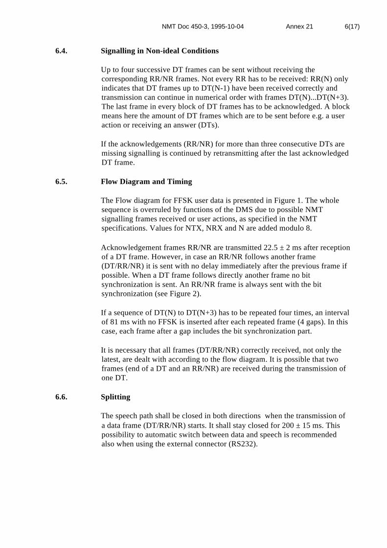
NMT Doc 450-3, 1995-10-04 Annex 21 6(17)
6.4. Signalling in Non-ideal Conditions
Up to four successive DT frames can be sent without receiving thecorresponding RR/NR frames. Not every RR has to be received: RR(N) onlyindicates that DT frames up to DT(N-1) have been received correctly andtransmission can continue in numerical order with frames DT(N)...DT(N+3).The last frame in every block of DT frames has to be acknowledged. A blockmeans here the amount of DT frames which are to be sent before e.g. a useraction or receiving an answer (DTs).
If the acknowledgements (RR/NR) for more than three consecutive DTs aremissing signalling is continued by retransmitting after the last acknowledgedDT frame.
6.5. Flow Diagram and Timing
The Flow diagram for FFSK user data is presented in Figure 1. The wholesequence is overruled by functions of the DMS due to possible NMTsignalling frames received or user actions, as specified in the NMTspecifications. Values for NTX, NRX and N are added modulo 8.
Acknowledgement frames RR/NR are transmitted 22.5 ± 2 ms after receptionof a DT frame. However, in case an RR/NR follows another frame(DT/RR/NR) it is sent with no delay immediately after the previous frame ifpossible. When a DT frame follows directly another frame no bitsynchronization is sent. An RR/NR frame is always sent with the bitsynchronization (see Figure 2).
If a sequence of DT(N) to DT(N+3) has to be repeated four times, an intervalof 81 ms with no FFSK is inserted after each repeated frame (4 gaps). In thiscase, each frame after a gap includes the bit synchronization part.
It is necessary that all frames (DT/RR/NR) correctly received, not only thelatest, are dealt with according to the flow diagram. It is possible that twoframes (end of a DT and an RR/NR) are received during the transmission ofone DT.
6.6. Splitting
The speech path shall be closed in both directions when the transmission ofa data frame (DT/RR/NR) starts. It shall stay closed for 200 ± 15 ms. Thispossibility to automatic switch between data and speech is recommendedalso when using the external connector (RS232).

NMT Doc 450-3, 1995-10-04 Annex 21 7(17)
7. USER DATA SECURITY
The FFSK user data transfer provides an optional internal scrambling facility(see paragraph 10). The specified scrambling method, though consideredvery effective in mobile use, may be further boosted by additional end to endencryption of data in the application when the connector for external dataequipment is used.
8. ADDITIONAL FUNCTIONS
8.1. Identity Check
In 7-bit format, the DMS can be forced to send its identifier*!MSI!*I1I2I3I4I5I6I7 followed by a Carriage Return (13) by sending to it aspecified command in a DT frame (user data). Characters MS identify thedata terminal type ('MS' for the DMS). For the DMS, I1...I7 are equal to ZX1 X2 X3 X4 X5 X6. Note that values for digits I1...I7 are used according toISO 7-bit character set. In some data services, this function can be used as anadditional check for authorization. The command is followed by a CarriageReturn (13) and has the following format: *?MSI?*. It occupies one DTframe. This message is not shown on the DMS display when received.
8.2. Automatic Answer
If automatic answer function has been activated the DMS goes electricallyoff-hook after receiving ringing order(s). The number of ringings beforeanswer may be presetable by the user. The DMS may have a possibility toanswer by a preprogrammable message (DT frames) after automatic answer.The automatic answer can be indicated to the caller by sending ControlFrame CT84 (filled with NULs, see 10.9.), preceded by RAND if scramblingis implemented (Paragraph 10). This will trigger the transmission of (ID andRAND plus) the telephone number of the calling DMS terminal (CT84, see10.9.) followed by a user data message (DT frames) if any.
off button is pressed (before fixed clearing). Manual hook-off shall stop thetransmission of the preprogrammed message. If manual hook-off is madebefore automatic answer, the preprogrammed message is not sent. If nomanual hook-off is made and no user data frames (DT/RR/NR) are receivedwithin 3-20 s after automatic answer, the DMS shall go on-hook.
The automatic answer function shall be clearly indicated when active. It shallbe possible to deactivate the function.

NMT Doc 450-3, 1995-10-04 Annex 21 8(17)
8.3. Controlling the Display
In 7-bit format, some special characters in the ISO 7-bit character set arereserved for controlling the MS display. To be able to clear the display andput new text into the display and into the receiving buffer if full, characterFF (12, Form Feed) is used. This clears the display and sets the cursor in theupper left position as well as clears the receiving buffer. A continuouslychanging display can be implemented this way.
Data received during previous calls should not be cleared in the memory.
To be able to also use data services not specially planned for a small display,a window technique should be used: a window of the size of the display ismoved across the page received. For continuous reading of the text, the nextline should appear at the end of the previous one if the window is movedbehind the end of the line (over a Carriage Return, CR = 13).
In some data services, it is useful to know the size of the MS display. Acommand for this has the format: *?DSZ?* (+CR). The answer to this is:*!DSZ!*CCCXLLL (+CR). CCC indicates characters per line and LLL isthe number of lines in the display (decimal values 000...999).
9. OPTIONAL CONTROL DATA
A control channel can be provided for data transfer for special purposes inaddition and as an alternative to the user data channel. Its capacity is partlyreserved for functions to be specified later and partly for non-standardapplications defined by the manufacturer.
Bit s in the DT frame Label is used for selection between user data andcontrol data. If s equals 1 the data part of the frame is received as user data.Value s = 0 indicates that the frame data part is for special use and shall notnormally be displayed. In this case, the 56 bits of the data part (xxx...) in aDT frame are regarded as control data (8 x 7 bits):
C D1 D2 D3 D4 D5 D6 D7
Parameter C (7 bits) defines the message and control data type (e.g. datascrambler handshaking) and D1...D7 (7 x 7 bits) give additional data ifrequired. Values C = 120 to 127 together with any values for D1 to D7 areintended for manufacturer dependent non-standard applications. Values C =0 to 119 are reserved for applications to be specified later. Parameter Calways follows next to the Label in each DT frame with control data. Controldata and user data cannot be included in one DT frame simultaneously.
In the flow diagram (Figure 1), no difference is made between user data andcontrol data: any DT frame may contain either type of data. Inacknowledgement frames (RR/NR), bit s is always sent as 1”.
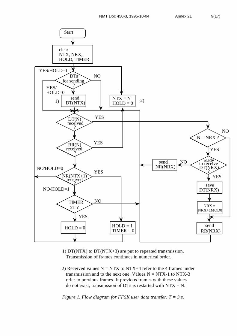
NMT Doc 450-3, 1995-10-04 Annex 21 9(17)
Start
clearNTX, NRX,HOLD, TIMER
DTsfor sending
?
YES/HOLD=1NO
YES/HOLD=0
sendDT(NTX)
NTX = NHOLD = 01) 2)
DT(N)received
?
RR(N)received
?
YES
YES
YES
YES
YES
NO
NO
NO
NO/HOLD=0
NO/HOLD=1
YES
HOLD = 0 HOLD = 1TIMER = 0
TIMER ≥T ?
NR(NTX+1)received
?
sendNR(NRX)
N = NRX ?
readyto receiveDT(NRX)
?
saveDT(NRX)
NRX =NRX+1MOD8
sendRR(NRX)
1) DT(NTX) to DT(NTX+3) are put to repeated transmission. Transmission of frames continues in numerical order.
2) Received values N = NTX to NTX+4 refer to the 4 frames under transmission and to the next one. Values N = NTX-1 to NTX-3 refer to previous frames. If previous frames with these values do not exist, transmission of DTs is restarted with NTX = N.
Figure 1. Flow diagram for FFSK user data transfer. T = 3 s.

NMT Doc 450-3, 1995-10-04 Annex 21 10(17)
from DMS to DMS
BIT SYNC
BIT SYNCDT (5)
DT (6)
RR (3)
DT(7)
DT (0)
RR (4)
DT (1)
RR (5)
DT (2)
RR (6)
DT (2)
RR (6)
RR (7)
DT (3)
RR (0)
DT (4)
RR (1)
DT (5)
RR (2)
DT (6)
Near simultaneousstart of datatransmission in bothdirections
°°°°°°
°°°°°°
from DMS to DMS
DT (1)
DT (2)
DT (3)
DT (4)
RR (0)
DT (5)
DT (6)
RR (1)
DT (7)
DT (0)
RR (2)
DT (1)
RR (3)
RR (1)
RR (2)
RR (3)
DT (7)
RR (4)
RR (5)
DT (0)
RR (6)
RR (7)
DT (1)
RR (0)
DT (2)
RR (1)
DT (3)
600 bit/s
22,5 ms
Reception of datastarts duringtransmission ofdata
64,2 ms
93,3 ms
355 bit/s
+355 bit/s
°°°°°°
°°°°°°
°°°°°°
°°°°°°
Each RR has a bit synchronization though not shown.
RR only updates parameters (NTX, HOLD) when received.
Figure 2. Two examples of duplex data transmission.

NMT Doc 450-3, 1995-10-04 Annex 21 11(17)
10. DATA SCRAMBLING METHOD FOR THE DMS (OPTION)
10.1 General
To be able to access public data networks and private data bases wheresubscriber identities, passwords and other confidential information aretransferred, data scrambling is often desired. The method described hereprovides basic scrambling only and has been designed for implementationalso in hand portable equipment (HMS). However, it makes it very difficultfor a third party to read the information exchanged between two DMSterminals on the radio path. If utmost security is required more advanceddata encryption methods (e.g. DES) shall be used in addition in specificapplications.
At the beginning of the data connection, both DMS terminals send randomnumbers (RANDA and RANDB) to each other. These random numbers areused at both ends to calculate data scrambling masks (ki). Using ki the datacan be scrambled and descrambled at both ends but not by a third party whodoes not know ki. In addition, a scrambling key (KS) is used in generatingki. Because different scrambling keys can be used for different DMSs, theidentity of the calling DMS is sent at the beginning of the connection. Thisrequires key management which is not described in this document.
10.2 Operation
The scrambling key KS is entered into the DMS by using the keyboard. Thelength of KS is 32 bits and it is entered as 8 hexadecimal characters using theDMS keyboard.
The scrambling is activated at the beginning of the data connection and it ismaintained throughout the connection. All user data (not control data) isscrambled after exchanging RANDs.
The DMS terminal requesting scrambling sends RAND before data frames(DTs). This also indicates whether 8-bit data or 7-bit data is used. If a DMSterminal has the scrambling function it shall be capable of sending its ID andfacilitating 7-bit format and optionally 8-bit format. In case of a positiveresponse to the RAND (see paragraph 10.6), the random numbers areexchanged and scrambling is started. The terminal initiating the call sends IDbefore RAND. If a DMS terminal has not the scrambling facility, the RANDwill be acknowledged by standard RR frames (s=1), no scrambling is startedand 7-bit format is used.

NMT Doc 450-3, 1995-10-04 Annex 21 12(17)
10.3 Definition of RAND and ID Control Data Frames (CT) andMASK
Reception of RAND triggers the transmission of the first frame(s): The A-subscriber terminal shall send ID+RAND and the B-subscriber terminal justRAND (never ID). If answer is made automatically, RAND is sent even ifthere is no data for sending. The three first characters (7 or 8-bit in binary,depending on format in use) of the first DT frame during the call are used asa mask (MASK = S1 S2 S3) for the rest of the characters.
Frame C D1 D2 D3 D4 D5 D6 D7 (see paragraph 9)
RAND 82 A1'A1 A2'A2 A3'A3 7/8, where
A1'A1...A3'A3 is a 24-bit randomnumber RAND where A1'...A3'(x000000) carry the MSBs (x above) ofthe 8-bit numbers R1 R2 R3, and
7/8 is ISO character 7 or 8 correspondingthe character length in DT frames.
ID 73 I1 I2 I3 I4 I5 I6 I7, where
I1...I7 = Z X1 X2 X3 X4 X5 X6 for theDMS. For terminals without NMTidentity, Z = 'F'. (Identity can also beobtained scrambled with user data byusing command *?MSI?* etc.).
Note: The remaining bits (0's) in A1'...A3' may later be specified to havevalues different from zero.
10.4 The Scrambling Method
10.4.1 The Scrambling Key Ks
The additional scrambling key can be divided in 4 parts:
KS = KS1 KS2 KS3 KS4 (4 x 8 bits)
The length of each part is 8 bits. If no KS has been entered into the DMSterminal, four last dialled digits when initiating a call, or four last digits ofthe DMS identity when receiving a call, are used according to ISO 7-bitcharacter set with leading '0' 7-bit characters if required. A leading zero isadded to each character (0xxxxxxx).
NMT Doc 450-3, 1995-10-04 Annex 21 13(17)
10.4.2 The Random Numbers
A random number RAND is sent from the DMS at the beginning of the datatransmission. The random number is divided in three parts:
RAND = R1 R2 R3 (3 x 8 bits)
A random number, MASK, is sent in the first DT frame when the actualscrambled data transmission starts. The three first characters, S1 S2 S3 inbinary, of the first DT frame are sent scrambled and shall be descrambledwhen received assuming zero values for them in the scrambling anddescrambling algorithm. The fourth character sent or received is the first ofactual data.
MASK = S1 S2 S3 (3 x 8 bits or 3 x 7 bits)
Values S1...S3 (non zero) are selected arbitrary for masking the data bytes tofollow. They are normally different in the two directions.
10.4.3 The Algorithm
At the beginning of the data connection, the DMS terminals exchangeRANDs (RANDA from DMSA and RANDB from DMSB):
RANDA = RA1 RA2 RA3 (3 x 8 bits)RANDB = RB1 RB2 RB3 (3 x 8 bits)
At both ends, a calculation is made:
K1 = RA1 XOR RB1 XOR KS1 (8 bits)K2 = RA2 XOR RB2 XOR KS2 (8 bits)K3 = RA3 XOR RB3 XOR KS3 (8 bits).
The transmitted Qi (i = 1,2,3,...) are scrambled:
Qi = Mi XOR ki XOR Sj (8 bits), i = 1,2,3..., j = (i-1) MOD 3 + 1
where Mi is the character to be scrambled,ki is obtained as described below.
ki = xi XOR yi XOR zi XOR ei (8 bits), i = 1,2,3,...
wherexi+1 = ( 81 * xi + 73) MOD 100, x0 = K1yi+1 = (167 * yi + 83) MOD 99, y0 = K2zi+1 = ( 14 * zi + 157) MOD 169, z0 = K3.ei+1 = ( 43 * ei + 39) MOD 49, e0 = KS4.

NMT Doc 450-3, 1995-10-04 Annex 21 14(17)
Calculation for descrambling (in reception) is done independently ofscrambling but with the same keys. It is similar except for:
Mi = Qi XOR ki XOR Sj (8 bits), i = 1,2,3,..., j = (i-1) MOD 3 + 1
In case of 7-bit data the MSBs are omitted in Qi and Mi.
In a DT user data frame, NUL characters (binary 0000000 or 00000000)are not scrambled (and i NOT incremented) but are transmitted as NULcharacters. Also, if scrambling a character leads to a zero (equal to NUL),the character is not scrambled (i will be incremented however). Indescrambling, NULs are received as NULs and if descrambling of acharacter leads to a NUL it is not descrambled but taken as received.
In the implementation, lists of pre-calculated values for xi, yi zi and ei can beused instead of real time calculation if required. Then, the starting points x0,y0, z0 and e0 in the sequences of numbers (lists) are the values obtainedfrom K1, K2, K3 and KS4 for the four lists respectively. Note that for thefirst character sent, i = 1. Lengths of the four lists are 100, 99, 169 and 49bytes.
10.5 Entering the Additional Scrambling Key into the DMS
The scrambling key to be entered into the DMS is:
KS = KS1 KS2 KS3 KS4 (4 x 8 bits)
This is entered as 8 hexadecimal characters of 4 bits e.g. by using the DMSkeyboard. The key may be attached to a dialled digit memory locationtogether with the telephone number and to the automatic answer functionwhen desired.
10.6 Procedures
At the beginning of the call, a DMS requesting scrambling always sends aCT with RAND before any DTs. ID is sent before RAND by the A-subscriber terminal. No DTs can be sent before RANDs have beenexchanged: transmitted and acknowledged. If RAND and a positive response(RR(N) with bit s=0 and N one greater than in the RAND transmitted) arereceived, transmission of scrambled DTs may start. If a negative response(RR(N) with bit s=1 and N one larger than in the RAND transmitted) isreceived, DTs are sent without scrambling. A typical sequence (as a result ofthe DMS specification, Fig.1) of the first frames is:

NMT Doc 450-3, 1995-10-04 Annex 21 15(17)
Transmitted Received ID CT(0)RAND CT(1) RR(1)RAND CT(1) RRp(2) Positive Response (s=0) *)
CT(0) RANDRRp(1) RRp(2)
Scrambled data DT(2) CT(0) RAND (+ MASK) RRp(1) RRp(3)
Scrambled data DT(3) RRp(4)DT(4) RRp(5) etc.
or: ID CT(0)RAND CT(1) RR(1)RAND CT(1) RR(2) Negative response (s=1)
Data without DT(2) RR(2)scrambling DT(3) RR(3)
DT(4) RR(4)DT(5) RR(5) etc.
*) Note that with a poor signal RR(0) with s=1 may be received before apositive response (s=0). Data can only be sent (scrambled) or displayed(descrambled) either 1) after receiving a negative response to RAND or 2)after receiving both RAND and a positive response. NR(N) is not sent herewhile waiting.
When RS232C connector is used, CT(0) with ID may be sent by the A-subscriber terminal continuously to test when the connection between theDMS terminals is established. In this case, RAND shall be sent only afterreception of an RR.
10.7 7/8-bit Format Selection
If scrambling has been requested by the DMS (RAND sent), the transmissionof DTs may start only after receiving a RAND and a positive response orafter receiving a negative response (no scrambling) to the RAND sent. If theDMS is set to operate in 8-bit format it shall transmit the RAND with 8-bitformat indication (D7='8') but the received RAND determines the format: ifa RAND with an indication on 7-bit format (D7='7') is received, 7-bit format(default) shall be used. A positive response is sent to both indications if theDMS has the scrambling facility. A negative response will be transmitted ifscrambling is not implemented in the DMS. To summarise, parameter D7 inthe RAND frame:

NMT Doc 450-3, 1995-10-04 Annex 21 16(17)
Transmitted Received Format usedD7 = '7' D7 = '7' + pos.resp. 7-bit, scramblingD7 = '7' D7 = '8' + pos.resp. 7-bit, scramblingD7 = '8' D7 = '7'+ pos.resp. 7-bit, scramblingD7 = '8' D7 = '8'+ pos.resp. 8-bit, scramblingD7 = '7'or '8' negativeresponse
7-bit, no scrambling
In the 8-bit format, the first 7-bit slot of a DT contains the MSBs(mmmmmmm) of the 7 bytes (xxxxxxx) in the same order:
101010101010101 00101000111 dsppnnn 11 mmmmmmm 11 xxxxxxx 11
xxxxxxx ... 11 xxxxxxx 11 xxxxxxx 11 ccccccc 11 ccccccc 11 cc
When the 8-bit format is active (in use) the DMS shall be fully transparent todata. That is, even if strings *?MSI?* and *?DSZ?* are received they arepassed through and no responses to them are sent.
10.8 Dealing with NUL Characters
A DMS with scrambling facility should also be capable of transferring NULcharacters via the external connector when provided. As the DT frame lengthis fixed and NUL characters are used for filling the last unused locations ofthe frame, those NUL characters which are intended for transmission cannotbe situated as the last characters of the frame. In cases where this wouldhappen, a new DT frame shall be started with the NUL as the first character.Examples of single DT frames (8-bit format):
Frame Content (X=NUL) Transmitted characters (X=NUL)
1 2 3 4 5 X X 1 2 3 4 51 X 2 3 X 4 X 1 X 2 3 X 4X X X X 1 2 3 X X X X 1 2 3X 1 2 3 X X X X 1 2 3X X X X X X X X
10.9 Control Data Transmission Frames (CT)
A Control Frame is similar to a User Data Frame (DT) except for bit s whichis 0 for a CT. Acknowledgements (RR/NR) concerned, no difference is madebetween DTs and CTs. However, to a RAND, a positive response can begiven by resetting bit s in all following RR/NRs. CTs always use 7-bitformat and are not scrambled.

NMT Doc 450-3, 1995-10-04 Annex 21 17(17)
In addition to RAND and ID, other CTs have been specified:
Frame C D1 D2 D3 D4 D5 D6 D7 (= Info part, 8 x 7 bits)
CT0 0 NUL NUL... NUL Idle Control Frame. Data part hasonly NULs (binary zeros). CT0 canbe optionally used for checking ifRR/NRs can be received (data linkexists).
CT84 84 N N N N N N N84 N N N N N<CR>NUL
CT84 can optionally be used to sendthe complete telephone number(NNN..., ISO 7-bit format) of the A-subscriber, as programmed by theuser into the DMS, followed by aCarriage Return. Several frameswith C=84 may be used. A CT84with D1...D7 = NUL can be used toindicate automatic answer and as atelephone number request by the B-subscriber terminal.

NMT Doc 450-3, 1995-10-04 Annex 22 1(6)
ANNEX 22
MOBILE STATION INTEGRATED WITH APORTABLE DATA TERMINAL OR PERSONALCOMPUTER.(CTMS)
A DEFINITION
A CTMS is defined as a single (i.e. non-separable) easily carried unitcombining the NMT transceiver with computer-terminal or PC facilities. TheCTMS contains its own visual display, operating controls and antenna.
B TECHNICAL REQUIREMENTS
A CTMS shall fulfil the requirements for an ordinary mobile station with thefollowing exceptions and additional requirements. (The paragraphnumbering below is referring to the main NMT Doc 450-3.) All paragraphsmarked with * apply only to CTMS with output power limited to 1.5 W. (I.e.based on the HMS specification.)
1 GENERAL
1.3.5 Extreme test conditions
The user interface of the CTMS (e.g. display, keypad and acoustic devices) isnot required to remain functional outside the normal test conditionsdescribed in NMT Doc 450-3 paragraph 1.3.4.
When applying for Type Test it shall be stated by the manufacturer withinwhat temperature & humidity range the complete CTMS is designed towork.
Testing in extreme conditions shall nevertheless be carried out where suchtests are specified in NMT Doc 450-3. However all testing outside the rangespecified by the manufacturer, is then carried out through a test terminalaccording to paragraph 1.3.2.1.
2 TRANSCEIVER UNIT
2.2.4 Transmitter carrier power
The available steady-state carrier output power at the antenna terminal maybe limited to 1.5 W ± 2 dB
2.2.5 Transmitter carrier control
If the output power is limited, the transmitter shall still be capable ofchanging the transmitter carrier output power as controlled by the Logic andControl Unit to -10 dB ± 3 dB (low power) relative to nominal carrier outputpower 1.5 W (high and medium power) at normal and extreme test

NMT Doc 450-3, 1995-10-04 Annex 22 2(6)
conditions. However, at any test condition the carrier output power shall notdeviate more than 3 dB between any arbitrary radio channel.
2.2.9 Frequency deviation
2.2.11 Adjacent channel power
If it is not possible to apply the test modulation signal in the tests "2.2.9Frequency deviation" and "2.2.11 Adjacent channel power" the testmodulation signal shall be that, as agreed between the manufacturer andtesting authority, which requires the greatest radio frequency occupiedbandwidth. Details on this test modulation signal shall be included in the testreport.
2.3.7.1 RF-sensitivity *
The maximum RF signal level difference between any arbitrary channels toget the same SINAD(P)-ratio shall not exceed 3 dB at any test condition.
2.3.9 Adjacent channel selectivity *
The adjacent channel selectivity shall not be less than 67 dB under normaltest conditions and 60 dB under extreme test conditions.
2.3.11 Spurious response rejection *
The spurious response rejection shall be at least 67 dB.
2.4.3 Interference in the ∅∅-signal frequency band *
The interference level in the looped ∅-signal channel shall not exceed incase a) -5 dB and in case b) -10 dB relative to the signal level.
2.4.4 Relative frequency intermodulation product level in the ∅∅-signalband *
The intermodulation product level in the looped ∅-signal channel shall notexceed -5 dB relative to the ∅-signal level.
3 OPERATIONAL CONTROLS UNIT (OCU)
3.3 Handset
A handset is optional on the CTMS.
If a handset or any other form of acoustical coupler is to be marketedtogether with the CTMS, it shall fulfil applicable acoustical requirements asspecified in NMT Doc 450-3 Chapter 2.

NMT Doc 450-3, 1995-10-04 Annex 22 3(6)
3.4 "Hands-Free" operation - "Hands-Free" button
"Hands-Free" operation need not be foreseen. In case "Hands-Free" facilitiesare provided, all the requirements in paragraph 3.4 shall be fulfilled.
3.9 Visual indicators
The visual indicators need not be visible in darkness, which means that theyneed not be illuminated or light emitting.
The indicators need not to be coloured.
The NMT indicators need not be continuously visible. However the usershall always have an easy possibility to enable the NMT indicators if he sodesires.
If the CTMS enter the "Roaming Alarm" state, the roaming alarm indicatorshall unconditionally appear to the user.
The visual roaming alarm indicator may be replaced by an acoustic signal.
In any case it shall remain active until roaming updating has been performedor the user actively cancels the indication.
4 OPERATIONAL PROCEDURES
This chapter is changed in accordance to changes in NMT Doc 450-3,Chapter 4.
The CTMS may be equipped with automatic call set-up and answeringfacilities.
During manual call set-up, answering and terminating, if provided, theCTMS shall fulfil all operational requirements for an ordinary MS. Howeverthe enabling of call set-up procedures may be through equipment specificoperations.
In other states, the meaning of the push-button set may be changed. Howeverthe user shall always have a one-step access to the "on-hook" function.

NMT Doc 450-3, 1995-10-04 Annex 22 4(6)
6 SYSTEM TESTS
6.4 Functional test
The functional tests are carried out on the test site mentioned in paragraph1.3.11 at various RF signal levels.
C Additional technical requirements
1 Antenna efficiency, transmitter
When measuring the effective radiated power the test site mentioned inparagraph 1.3.11 shall be used.
The CTMS with its antenna shall be rotated in the horizontal plane 0-360°and the height of the test antenna shall be varied in the range from 1 to 4 mto obtain the maximum level on the test receiver. The test antenna shall bevertically polarized.
The effective radiated power Pr is determined by substitution measurement.
With the test antenna in the position giving maximum level on the testreceiver, the CTMS shall be rotated 0-360° in the horizontal plane and thelevel on the test receiver recorded.
Requirement: Pr shall in the maximum direction not be less than 3 dB belowthe power measured in an artificial antenna.
2 Receiver sensitivity degradation, Antenna-efficiency, receiver
When measuring the receiver part of the CTMS the test site mentioned inparagraph 1.3.11 shall be used.
The CTMS with its antenna and the test antenna shall be in the positiongiving maximum level on the test receiver, see paragraph 1 above.
The CTMS shall be in the condition of receiving ringing order. Thereference field strength, Eo, is the lowest level when the CTMS generatesringing locally as a response of frame 5a (L=9) with 95% receptionprobability.
The CTMS shall then be in the speech condition and the lowest field strengthfor a successful switching call in progress, Es, shall be noted. The level Es isthe lowest signal level for which switching call in progress is successful with95% probability during speech condition.
Requirement: The difference Es-Eo shall not be more than 3 dB.
This requirement shall be fulfilled independent of the CTMS output powerlevel.

NMT Doc 450-3, 1995-10-04 Annex 22 5(6)
3 Use of CTMS in vehicles.
The CTMS may be connected to an external antenna, external handset andthe power source of the vehicle. In case it is not possible to use theoperational and control buttons when the CTMS is connected, anotheroperational and control unit shall be used. The built-in batteries may becharged from the power source. When the CTMS is connected to externalantenna, handset or operational and control unit, the corresponding devicesin the CTMS shall be made inoperable.
Auxiliaries to CTMS which makes it possible or easier to use the equipmentin vehicles are called “car mounting kit” in the following text.
The combination of CTMS and its car mounting kit shall fulfil thespecifications given in NMT Doc 450-3 and Annex 3. The antenna terminalof the mounting kit towards the car antenna (corresponds to antenna interfaceE in Annex 18) is used as antenna terminal for measurements when testing acar mounting kit.
D SPECIAL TYPE TESTING- & OPERATIONALREQUIREMENTS
To accommodate the relaxationís from the ordinary MS-specification, thefollowing requirements shall apply:
1 The unit integrating a NMT transceiver and a computer terminal/PC isregarded as one single unit i.e. the whole unit shall be submitted to all testsdescribed in NMT Doc 450-3 and relevant annexes.
2 If the NMT transceiver is separated from the rest of the equipment by theuser, it shall become inoperable by all means.
3 All NMT functionalityís, including keyboard operations and visualindication, shall be unchangeable by the user, e.g. no local or hostapplication software shall interfere with the type approved functionalityís.
4 The requirements in Annex 1 to NMT Doc 450-3, shall apply i.e. one NMTtype designation shall be applied to the whole unit.
5 It shall be certified in written form that the handling & performance of theNMT radio interface & signalling is not changeable, relative to the typeapproved version, by any user action whatsoever. See figure 1 below!
6 The CTMS may utilize the BMS functionality. see Annex 12 to NMT Doc450-3.
7 The modulation method of the modem and the data transfer protocol shall notbe of such a type that it is interfering with the NMT-specific FFSK systemdata signalling.

NMT Doc 450-3, 1995-10-04 Annex 22 6(6)
8 The CTMS shall have a connector for an external antenna. This connectorshall be accessible to the user.
9 All requirements in Annex 19 remains valid for the CTMS and may not bereplaced by any integrated functionalityís.
Indicators
Hook switch& buttons
Pushbutton set
Display
LF Processing Circuits (TX)
LF Processing Circuits (RX)
TransceiverUnit
OperationalControls Unit
OCU
Logic &Controls Unit
LCU
Signallingequipment
NMT system interface partControlled by a dedicated processor & software beeingnon-adressable by the user interface processor or inputs.
User interfacepartControlledby applicationsoftware and/or user
LF Input
LF Output
Fig.1 Logical split between NMT system part and User interface part ofthe CTMS

NMT Doc 450-3, 1995-10-04 Annex 23 1(2)
ANNEX 23 (OPTION)
Specification for the bar coding of subscription management relatedinformation
A SCOPE
This Annex specifies the bar coding of the information related to the MStype designation and later transferred to the subscription managementsystem (SMS) upon opening a subscription to the network. The code is of atype that can be transferred via telefax to the SMS or via a light-pen datatransfer system.
No part of this annex overrules the requirements in the other parts of NMTDoc 450-3 or NMT Doc 900-3 e.g. the type designation shall be visuallyreadable together with serial number while the NMT-SIS reference numbershall be electronically readable from the MS.
B TECHNICAL REQUIREMENTS
1 Contents
1.1 The information shall consist of:
i) Manufacturer & Type designation, including version number (See Annex 1)
This field is a character exact representation of the type designation i.e. it iscorresponding to one type of MS only. If the manufacturers name is to bepart of the type designation it shall be included.
ii) Serial number.
No information such as ”Snr” shall be included. Every character in this fieldis to be understood as part of the serial number.
iii) NMT SIS reference number (See NMT Doc 900-3 paragraph 4.5)
This field shall only contain the relevant 18 characters, but may be split by”DOT” according to the structure of the reference number.

NMT Doc 450-3, 1995-10-04 Annex 23 2(2)
2 Type of code
2.1 The code used shall be EDI Code 39
2.2 An example of the code is shown below
M A K E A S M A K E A B C D 9 0 0 E F 1
1 2 3 4 5 6 7 8 9
1 2 3 4 1 2 3 4 5 6 1 2 3 4 5 1 2
MAKE A/S ABCD 900 EF 1
SNR:123456789
SIS REF NO: 1234.123456.12345.123
3 Placement and use
3.1 Use
The code is likely to be placed on the subscription form by the means of aself adhesive sticker or by reading it with a light pen thus transferring itelectronically.
3.2 Placing
The code shall either be placed directly on the MS or on the package. It isrecommended to enclose a duplicate which, in size, is suitable for faxtransmission.
NOTE: Any mismatch between the code and the actual hardware will not beidentified before the user attempts to use the MS.
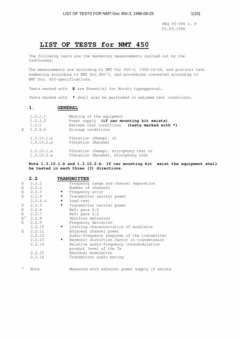
LIST OF TESTS FOR NMT-Doc 450-3, 1996-08-25 1(10)
MSg 93-594 v. 925.08.1996
LIST OF TESTS for NMT 450The following tests are the mandatory measurements carried out by thetesthouses.
The measurements are according to NMT Doc 450-3, 1995-10-04, and protocol testnumbering according to NMT Doc.900-5, and procedures converted according toNMT Doc. 450-specifications.
Tests marked with E are Essential for Nordic typeapproval.
Tests marked with * shall also be performed in extreme test conditions.
1. GENERAL
1.3.1.1 Marking of the equipment1.3.3.2 Power supply (if car mounting kit exists)1.3.5 Extreme test conditions (tests marked with *)
E 1.3.5.4 Storage conditions
1.3.10.1.a Vibration (Sweep), or1.3.10.2.a Vibration (Random)
1.3.10.1.a Vibration (Sweep), microphony test or1.3.10.2.a Vibration (Random), microphony test
Note 1.3.10.1.b and 1.3.10.2.b. If car mounting kit exist the equipment shallbe tested in each three (3) directions.
2.2 TRANSMITTERE 2.2.1 Frequency range and channel separationE 2.2.2 Number of channelsE 2.2.3 * Frequency errorE 2.2.4 * Transmitter carrier power
2.2.4.4 * Load testE 2.2.5 * Transmitter carrier powerE 2.2.6 Ref: para 6.2E 2.2.7 Ref: para 6.2E1) 2.2.8 Spurious emissionsE 2.2.9 Frequency deviation
2.2.10 * Limiting characteristics of modulatorE 2.2.11 Adjacent channel power
2.2.12 Audio-frequency response of the transmitter2.2.13 * Harmonic distortion factor in transmission2.2.14 Relative audio-frequency intermodulation
product level of the Tx2.2.15 Residual modulation2.2.16 Transmitter audio muting
1) Note Measured with external power supply if exists

LIST OF TESTS FOR NMT-Doc 450-3, 1996-08-25 2(10)2.3 RECEIVER:
E 2.3.1 Frequency range and channel separationE 2.3.2 Number of channelsE 2.3.3 Duplex separationE 2.3.4 Ref: Para 6.2.1 (protocol test 3.1.4.1)
2.3.5 Ref: Para 5.2.1.2 (protocol tests chapter 3.1 )E 2.3.7.1 * RF-sensitivityE 2.3.7.2 Receiver duplex sensitivity degradationE 2.3.8 Co-channel rejectionE 2.3.9 * Adjacent channel selectivityE 2.3.11 Spurious response rejectionE 2.3.12 Intermodulation rejectionE1) 2.3.14 Spurious emissions
2.3.15 * Harmonic distortion ratio2.3.16 Relative audio-frequency intermodulation
product level of RxE 2.3.17 Amplitude characteristics of receiver limitter
2.3.18 AM-suppression2.3.19 Noise and hum2.3.20 Audio frequency response2.3.21 Receiver audio muting
1) Note Measured with external power supply if exists
2.4 SUPERVISORY SIGNAL LOOP ANDTRANSCEIVER COUPLING
E 2.4.1 * Supervisory signal deviationE 2.4.2 Transceiver couplingE 2.4.3 Interference in the supervisory signal
frequency bandE 2.4.4 Relative audio-frequency intermodulation
product level in the supervisory signal loop
2.5 VOICE PROCESSING, TX
E 2.5.1 Compression linearityE 2.5.2 Transient response of the compressorE 2.5.3 Attack and recovery time of the compressorE 2.5.4 Send frequency responseE 2.5.5 Send loudness ratingE 2.5.6 Transmit distortionE 2.5.7 Transmission idle noiseE 2.5.8 Noice cancelling device (if implemented)E 2.5.9 Separate microphone (if implemented)
2.6 VOICE PROCESSING, RX
E 2.6.1 Expansion linearityE 2.6.2 Transient response of the expanderE 2.6.3 Receive frequency responseE 2.6.4 Receive loudness ratingE 2.6.5 Receive voice controlE 2.6.6 Receive harmonic distortionE 2.6.7 Receive idle noise
2.6.8 Maximum sound level of handset earpiece2.6.9 Volume control in "Hands-Free" mode
(if implemented)
E 2.7 STABILITY LOSS
E 3. OPERATIONAL CONTROLS UNIT
E 4. OPERATIONAL PROCEDURES
LIST OF TESTS FOR NMT-Doc 450-3, 1996-08-25 3(10)The mobile station shall be checked according to theparagraphs in chapter 3 and 4.
E 5. LOGIC AND CONTROL UNIT AND SIGNALLING EQUIPMENT
See protocol tests
E 6. SYSTEM TESTS
E 6.2.6 Transient behaviour of the transmitter
Other tests see protocol tests
ANNEX 1General information concerning tests, type-approval and marking
The mobile station shall be checked according to the paragraphs inAnnex 1.
E*) ANNEX 2PORTABLE MOBILE STATION
If the mobile station is a Portable it shall be tested according to theparagraphs in Annex 2.
*) Essential except 1.3.10, 5.2.1.3 and C3
E*) ANNEX 3HANDHELD MOBILE STATION (HMS)
If the mobile station is a Handheld it shall be tested according to theparagraphs in Annex 3.
*) Essential except 1.3.10, 5.2.1.3 and C3
ANNEX 4PRIORITY MOBILE STATION (PMS)
If the mobile station is a Priority it shall be tested according to theparagraphs of Annex 4.Reference: Protocoltests in NMT Doc 900-5, October 1993
ANNEX 5PAY-PHONES
If the mobile station is a Pay-phone it shall be tested according to theparagraphs of Annex 5.Reference: Protocoltests in NMT Doc 900-5, October 1993

LIST OF TESTS FOR NMT-Doc 450-3, 1996-08-25 4(10)ANNEX 6MFT FUNCTION
If the mobile station has MFT function it shall be tested according to theparagraphs of Annex 6.Reference: Protocoltests in NMT Doc 900-5, October 1993
ANNEX 7INTERFACE FOR EXTERNAL EQUIPMENT
If the mobile station has Interface for external equipment it shall be testedaccording to the paragraphs of Annex 7.
ANNEX 8REGISTER RECALL FUNCTION
If the mobile station has Register Recall Function it shall be tested accordingto the paragraphs of Annex 8.Reference: Protocoltests in NMT Doc 900-5, October 1993
ANNEX 9COMBINED USE (HMS WITH BOOSTER)
If the mobile station is for Combined use (HMS with booster) it shall be testedaccording to the paragraphs of Annex 9.
E 2.2.4 * Transmitter carrier powerE 2.2.5 * Transmitter carrier power controlE 2.2.6 Ref: para 6.2.6 in NMT Doc. 900-3E 2.2.8 Spurious emissionsE 2.2.11 Adjacent channel powerE 2.3.1 Frequency range and channel separationE 2.3.7.1 * RF-sensitivityE 2.3.7.2 Receiver duplex sensitivity degradationE 2.3.9 * Adjacent channel selectivityE 2.5.7 Transmitter idle noise
ANNEX 11EQUIPPED WITH MORE THAN ONE HANDSETAND/OR CONTROL UNITS
If the mobile station is Equipped with more than one handset and/or controlunits it shall be tested according to the paragraphs of Annex 11.
E*) ANNEX 12BATTERY SAVING FUNCTION
If the Handheld mobile station has Battery saving function (BMS) it shall betested according to the paragraphs of Annex 12.Reference: Protocoltests in NMT Doc 900-5, October 1993
*) Essential if implemented

LIST OF TESTS FOR NMT-Doc 450-3, 1996-08-25 5(10)ANNEX 16RANDOM GENERATOR
Mobile station with SIS function shall fulfil requirements according to theparagraphs of Annex 16.
Reference: Verifying security in NMT-SIS. ”Letter to Manufacturers of NMT900”... MS 90-36, NMT Doc 90-2320 dated 01.09.1990 and ”Laboratory test report,verifying security in the NMT 900 and NMT 450 mobiles with SIS”, MSG 93-0595and ”Manufacturers test report, verifying security in the NMT 900 and NMT 450mobiles with SIS”, MSG 93-0596
E*) ANNEX 17COMBINED NMT-450/900
If the mobile station is for Combined use NMT 450/900 it shall be testedaccording to the paragraphs of Annex 17.
*) Essential if implemented
ANNEX 18EXTERNAL EQUIPMENT NOT SPECIFIED ELSEWHERE
If the mobile station is equipped with External equipment not specifiedelsewhere in the specifications it shall be tested according to the paragraphsof Annex 18.
ANNEX 19SERVICE MODE AND PROGRAMMING MODE
Mobile station shall fulfil requirements according to the paragraphs of Annex19.
ANNEX 20CORDLESS HANDSET
If the mobile station is equipped with a cordless handset it shall be testedaccording to the paragraphs in Annex 20
ANNEX 21FFSK USER DATA FACILITY (DMS)
If the mobile station is a DMS it shall be tested both like normal MS andaccording to the paragraphs of Annex 21 because DMS function is activesimultaneously with normal NMT-functions.Reference: Protocol tests in NMT Doc 900-5
Annex to NMT-Doc 900-5;MSg-document 91-0417/1 which are pure NMT-function tests during DMSconnection.MSg-document 93-0589 which are pure DMS-function tests via speechpath.Check lists for the DMS-tests are valid, despite the TH1 and LF1indicators.
ANNEX 22PORTABLE DATA TERMINAL OR PERSONAL COMPUTER (CTMS)
If the mobile station is A CTMS it shall be tested according to the paragraphsof Annex 22.

LIST OF TESTS FOR NMT-Doc 450-3, 1996-08-25 6(10)
PROTOCOLTest numbering according to NMT Doc.900-5, and procedures converted accordingto NMT Doc. 450-specifications
All tests shall be carried out with at least two false frame synchronization inthe mobile subscriber number, and only in normal test conditions.
3. FUNCTIONAL TESTS, IDEAL CONDITIONS
3.1 TEST OF THE MAIN STATES FOR LCU IN MS
E 3.1.2al Staying on a CC when a short reduction in RF-leveloccurs, MS
E 3.1.2a2 Search for CC when the RF-level is too low, MS
E 3.1.2bl Search for CC when two call attempts are made with lessthan 10 sec interval
E 3.1.2b2 Staying on a CC when two call attempts are made with morethan 10 sec interval
E 3.1.2cl Remain on CC when two frames are lost between two correctframes
E 3.1.2c2 Start searching for a new CC when 3 frames are lostbetween two correct frames
E 3.1.3 The MS power supply is interrupted during conversation,(only if MS is connected to EXT. DC)
E 3.1.4.1 Measuring the scan time
3.2 ROAMINGE 3.2.1aA Succesful roaming updating in basic band, level A
E 3.2.1aB Succesful roaming updating in basic band, level B
E 3.2.1aC Succesful roaming updating in basic band, level C
E 3.2.2.1 Unsuccesful roaming updating and then updating with DDMnot empty
E 3.2.2.2 Unsuccesful roaming updating and then updating with DDMempty
3.2.2. 3 Unsuccesful roaming updating and then automatic updatingafter one minute (optional)
E 3.2.3A Control of the specified delay of roaming updating, level A
E 3.2.3B Control of the specified delay of roaming updating, level B
E 3.2.3C Control of the specified delay of roaming updating, level C
3.3 TRAFFIC CHANNEL OR COMBINED TC/CC
E 3.3.1 Traffic channel or combined TC/CC seizure
3.4 CALL MTX-MS INCLUDING FIXED CLEARING
E 3.4.1.1 Call MTX -> MS and clearing of the call before MS answers
E 3.4.1.2 Call MTX -> MS on a combined CC/TC
E 3.4.2 Call MTX -> MS with answer from MS

LIST OF TESTS FOR NMT-Doc 450-3, 1996-08-25 7(10)E 3.4.3 Call MTX -> MS, Scheme B1
3.5 CALL MS-MTX INCLUDING MS CLEARING
E 3.5.1 Call MS -> MTX on a traffic channel, including MS clearing
E 3.5.1.1AS Call MSas -> MTX on a traffic channel, including MSclearing, added security
E 3.5.1.2AS Call MSas -> MTX on a traffic channel with incorrectframe 7, added security
E 3.5.1.3AS Unsuccesful Call MSas -> MTX on a traffic channel withincorrect frame 7, added security
3.6 SWITCHING CALL IN PROGRESSE 3.6.1.1 Succesful switching call in progress, ordinary procedure
E 3.6.1.3 Succesful switching call in progress with RF-level>24 dB(µV) E.M.F, short procedure
E 3.6.1.4 Succesful switching call in progress with RF-level<16 dB(uV) E.M.F, short procedure
E 3.6.2.1 Unsuccesful switching call in progress, ordinary procedure
E 3.6.2.2 Unsuccesful switching call in progress, short procedure
3.7 CHANGE OF MS OUTPUT POWER LEVEL
E 3.7.1 Change of MS output power level on same channel duringconversation
E 3.7.2 Change of MS output power level on TC
3.8 COUNTRY SELECTORE 3.8.1 Change of country selector (no valid YlY2)
E 3.8.2a Change of country selector (valid YlY2)
Note Country selector tests essential if implemented
3.9 AUTONOMOUS TIME-OUT OF MSE 3.9.1 Switch off all power in MS after complete loss of RF input
signal
E 3.9.2 Autonomous time-out of MS power during burst of RF inputsignal
E 3.9.3 Autonomous time-out of MS power during short bursts of RFinput signal
E 3.9.4 Autonomous time-out MS receiving continuous FFSK signallingduring conversation

LIST OF TESTS FOR NMT-Doc 450-3, 1996-08-25 8(10)
ADDITIONAL TESTSE 3.14AS Authenticat ion request during conversation
E 3.15 Checking the compander/expander state "manual checking"
4. FUNCTIONAL TESTS, NON-IDEAL CONDITIONS
E 4.1.1 Control of the error-correcting code
E 4.1.2 Control of acceptance of signals
E 4.1.3 False frame synchronizationReference: Para 4.7.1 NMT Doc. 450-1
Phase shift, 0-160 bits in steps of ten (10).
E 4.1.3.a False frame syncronization (improved test)
E 4.1.3.b False frame syncronization (improved test)
E 4.1.3. c False frame syncronization (improved test)
5.PERFORMANCE TESTS
E 5.1 Signalling sensitivity measured by call receptionprobabilityReference: Para 6.1.1. NMT Doc. 450-3
E 5.5 Signalling sensitivity in presence of RF signal fadingmeasured by call reception probabilityReference: Para 6.1.5 NMT Doc. 450-3
E 5.8.1.10a Start up and decay times (frame lOa)
E 5.8.2.1 Switching time to next channelReference: Test 3.1.4.1, List of test
E 5.8.2.2 Switching time to ordered channelReference: Para 6.2.5 NMT Doc. 450-3
E 5.8.3 Power reduction
E1) 5.9.MAN Receiver duplex sensitivity degradation(Manual test not on the tape)
Min. 100 attempts.
1) For portable MS and handheld MS there is alternative testmethod in Annex 2 and Annex 3
6. MS RESPONSE IN ABNORMAL SITUATIONS
E 6.1 MS off-hook while initiating a roaming procedure
E 6.2.1 Waiting time for additional ringing order within 30 sec.
E 6.2.2 Not received ringing order within 30 sec.
E 6.2.3 Waiting time for first ringing signal
E 6.3.1 Sensitivity for MTX-clearing in signalling scheme A, callMS -> MTX
E 6.3.2 Sensitivity for MTX-clearing in signalling scheme A, callMS -> MTX
E 6.4 MS sensitivity of frame 5a (L=6) in signalling scheme A
E 6.5 MS switched off by on/off switch during conversation

LIST OF TESTS FOR NMT-Doc 450-3, 1996-08-25 9(10)
Total 84 Tests
ADDITIONAL TESTS
ANNEX 4 PRIORITY MOBILE STATION (PMS)
3.11.1 Priority call with idle TC available at once
3.11.1AS Call MSas -> MTX with priority (PMS), idle TCavailable at once, added security
3.11.2 Priority call with no idle TC available at once (queued)
3.11.2AS Call MSas -> MTX with priority, no idle TCavailable at once (queued), added security
Total 4 Priority Tests
ANNEX 5 PAY-PHONE3.12 The tariff information intercharged between MTX and
coin box MS
3.12AS Call coin box MSas -> MTX, added security
Total 2 Pay-Phone Tests
ANNEX 6 MFT FUNCTION
3.10.1.1 Push button data transmission with MFT converter,manual transmission
3.10.1.2 MS clearing during MFT transmission
3.10.2 Push button data transmission, automatic transmission
Total 3 MFT Tests
ANNEX 8 REGISTER RECALL FUNCTION
3.13.1 Register recall function
3.13.lAS Register recall function, added security
Note: Tests are made DDM empty and not (automatic transmission)
Total 2 Register Recall Tests
ANNEX 12 BATTERY SAVING FUNCTION
E 3.1.2alBMS Staying on a CC when a short reduction in RF-level occurs, BMS
E 3.1.2a2BMS Search for CC when the RF-level is too low, BMS
E 3.1.2clBMS Staying on a CC, when two frames are lost in the awake period, BMS
E 3.1.2c2BMS Search for CC, when 3 frames are lost in the awake period, BMS
E 3.4.4 Call MTX -> handportable MS, battery saving period
E 3.4.4.lBMS Battery saving period, BMS
LIST OF TESTS FOR NMT-Doc 450-3, 1996-08-25 10(10)E 3.4.4.2BMS No calling channal present, BMS
E 3.4.4.3BMS Ignoring first BSO after locking to a CC, BMS
Total 8 BMS Tests
ANNEX 21 DATA MOBILE STATION FUNCTIONNMT-function tests during receiving and transmitting of data
3.6.1.1DMS Successful switching call in progress duringreceiving/transmitting of data, ordinary procedure
3.6.1.2DMS Successful switching call in progress duringreceiving/transmitting of data, improved procedure
3.6.1.3DMS Successful switching call in progress duringreceiving/transmitting of data, with RF-level>24 dB (µV) E.M.F., short procedure
3.6.1.4DMS Successful switching call in progress duringreceiving/transmitting of data, with RF-level<16 dB (µV) E.M.F., short procedure
3.6.2.1DMS Unsuccessful switching call in progress duringreceiving/transmitting of data, ordinary procedure
3.6.2.2DMS Unsuccessful switching call in progress duringreceiving/transmitting of data, short procedure
3.7.1DMS Change of DMS output power level on same channelduring receiving/transmitting of data
3.9.1DMS Switch off all power in DMS after complete loss of RFinput signal. Data receiving/transmitting is on before thecomplete loss of RF input signal
3.9.2DMS Autonomous time-out of DMS power during burst of RFinput signal, data receiving/transmitting is onduring the test
3.9.2DMS Autonomous time-out of DMS power during short bursts ofRF input signal, data receiving/transmitting is on duringthe test
5.8.3DMS Power reduction during receiving/transmitting of data
Total 11 DMS tests