Dual-frequency excitation: a novel method for probing the nonlinear ...

Nonlinear response of gear system based on anovel backlash model with coupling dynamicchange and surface topographyXin Yu
Wuhan UniversityYunyun Sun ( [email protected] )
Wuhan University https://orcid.org/0000-0002-4447-1408Hongguang Li
Shanghai Jiao Tong UniversityShijing Wu
Wuhan University
Research Article
Keywords: Dynamic backlash, Gear dynamics, Surface topography, Fractal method, Close-loop algorithm
Posted Date: October 5th, 2021
DOI: https://doi.org/10.21203/rs.3.rs-889901/v1
License: This work is licensed under a Creative Commons Attribution 4.0 International License. Read Full License

Nonlinear response of gear system based on a novel backlash model with coupling dynamic
change and surface topography
Xin Yu · Yunyun Sun* · Hongguang Li · Shijing Wu
Received: date / Accepted: date
Abstract Backlash is one of main nonlinear internal excitation factors in gear transmission system and therefore has been widely
concerned. Most existing models of backlash are based on a random constant, which ignore the dynamic characteristics of backlash
itself and the effects of surface topography. To model the backlash precisely, in this paper, the constant part of backlash is revised
through average height of all asperities in contact region related to surface roughness by fractal method. Simultaneously, the dynamic
part is modeled considering the displacement of gear center motion that comes from shaft deformation in coupling dynamic meshing. A
complete backlash model consisting of the two parts is established subsequently and a corresponding close-loop algorithm is proposed
to solve system dynamics by coupling mesh stiffness and time varying pressure angle. Through time history charts, phase portraits and
Poincare mapping as well as frequency spectrograms, calculation results clearly demonstrate the comprehensive effects of dynamic
backlash on the nonlinear dynamics involving vibration amplitude, frequency and chaotic characteristics of a spur gear pair. The effects
of surface topography on backlash and system nonlinear response including vibration amplitude and chaotic features are also analyzed,
therefore dynamic backlash and surface topography are important factors that cannot be ignored in gear issue. The comparison with
experimental data as well as other previous models is conducted to verify the superiority of proposed model.
Keywords Dynamic backlash · Gear dynamics · Surface topography · Fractal method · Close-loop algorithm
1 Introduction
As a convenient, efficient and precise form of transmission machineries, gear drive has been widely used in aerospace, reducer,
machine tool and other important fields [1][2][3]. With the popularization of gear application, the research on gears also gets more
common. The most basic knowledge in gear research is that the gear shows strong dynamic nonlinearity in the meshing process, which
is caused by the dynamic parameters contained in the gear itself. Among nonlinear factors, backlash between gear teeth maybe the main
internal excitation source and also an important factor affecting gear vibration, noise, impact and error. Besides, the influence of tooth
clearance on gear system is comprehensive at engineering practice, where the lubrication and wear [4] are also under effects of backlash.
Therefore, many scholars have long been committed to the study of backlash from different aspects. Walha et, al. [5] analyzed the
situation of contact loss at different backlash conditions combining time-varying meshing stiffness. The function of backlash illustrates
the influences of backlash on meshing directly, which has the form of piecewise with strong nonlinearity. Some scholars have tried to
improve the expression of backlash function. Moradi and Salarieh [6] researched the gear dynamic equation under piecewise nonlinear
backlash and approximated the equations by polynomials to study the response. Saghafi and Farshidianfar [7] used 3-order polynomials
to approximate backlash function and the chaos control of gear system was studied accordingly. Xiong et, al. [8] studied the coupling
effects of dynamic parameters by analyzing the influences of backlash on meshing stiffness from process of tooth manufacturing.
Although the research on backlash is broad, the core topic is always how to model the value of backlash accurately. In an early
time, backlash in the form of a sine function with periodicity was introduced into dynamic equation by Kahraman et, al. [9][10] and
effects of multiple clearances between gear and shaft were analyzed. This backlash fitting method has been widely used with backlash
values following normal distribution [11]. Because the backlash value is selected in the range of normal distribution, it has uncertainty
and is called stochastic backlash. Lu et, al. [12] proposed a model of stochastic backlash due to assembling error and studied its
influences. Chen et, al. [13] studied the effects of backlash on system stability based on the random backlash that obeys standard normal
distribution. Random backlash can show to some extent that it is essentially caused by manufacturing error, but the mean value of
normal distribution is still just random and have no reasonable realistic values. Thus, Chen et, al. [14] proposed a fractal backlash model
Xin Yu, Yunyun Sun* , Shijing Wu
School of Power and Mechanical Engineering, Wuhan University, Wuhan 430000, China
E-mail: [email protected]
Hongguang Li
State Key Laboratory of Mechanical System and Vibration, Shanghai Jiao Tong University, Shanghai 200000, China

2 Xin Yu et al.
to display the effects of surface morphology on backlash and compared it to normal constant backlash. Huang et, al. [15] analyzed the
chaotic characteristics of gear system based on fractal backlash. Although the value methods of gear backlash through the above models
are different, the models of backlash are all in a constant form.
Meanwhile, as the dynamic characteristics change in meshing process, the constant backlash is not accurate enough and dynamic
model of backlash has been proposed. Chen et, al. [16] proposed a dynamic backlash model due to gear center motion with an invariant
pressure angle. Yang et, al. [17] considered the backlash of planetary gears as an alternating meshing mechanism and represented
backlash as dead zone of input torque. Li et, al. [18] established a dynamic backlash model with and without the effects of teeth
wear respectively and analyzed the difference of system response. Liu et, al. [19] introduced a dynamic backlash model related to
geometric eccentricity into lateral-torsional-rocking coupling gear model. Wang and Zhu [20] further applied the dynamic backlash
model to planetary gear train system and helical angle was taken into account. Wang et, al. [21] proposed a simplified dynamic backlash
model composed of two gears’ eccentricity, which has a form of angular displacement. Yi et, al. [22] researched the dynamics of gear
involving dynamic backlash under time-varying pressure angle. Shi et, al. [23] calculated comprehensive backlash of involute gear pair
considering various kinds of deformation and contact ratio.
Although model of backlash has been investigated by different methods, a simultaneous consideration to the physical meaning of
both invariant and variable parts of the backlash model is really rare. The absence of either morphology or dynamic backlash will
lead to incomplete backlash modeling and limited nonlinear response accuracy. In this paper, the motivation is to establish a complete
dynamic backlash model with regard to effects of gear center motion and microscopic morphology at tooth surface. The constant part of
proposed model employs fractal method to obtain effective mean value of surface roughness and subsequently backlash is decided. This
method can avoid the result that average height of all microscopic asperities always be zero no matter how rough the surface is due to
the equivalent plane of fractal theory and truly reflect the influences of all asperities entering contact. The time varying part of backlash
originates from gear center motion, which has inevitable influences on backlash. The relationship between gear center displacement
and variation of backlash is derived geometrically. Corresponding to the characteristics of dynamic backlash, a close-loop algorithm
is established to update the backlash value. The nonlinear response of system with proposed dynamic backlash model is solved and
validation by experiment is made.
2 Modeling of dynamic gear backlash
In essence, as Fig. 1 shows, since there is always a difference between the actual and ideal tooth thickness along the pitch circle
for various reasons, the backlash has inevitable existence. In a pair of meshing gears, the existence of the initial backlash will affect the
operation of the system and in turn cause the backlash itself to change.
actual
tooth thickness
ideal
tooth thickness
Fig. 1 Schematic diagram of gear backlash
As a result, backlash between meshing gears consists of constant and dynamic components. The constant part originates from initial
invariant parameters such as manufacture or installation errors and is affected by surface topography. While the time varying part roots
in the change of related parameters in actual dynamic meshing, among which the most important factor is the movement of gear center
[16][22]. The complete backlash can be expressed as
B(t) = bs +bdy(t) (1)
Herein bs denotes the constant part, bdy(t) is the time-variant part.

Nonlinear response of gear system based on a novel backlash model with coupling dynamic change and surface topography 3
2.1 Revised invariant part of backlash
Generally, the constant part of backlash is always set as a fixed value that confirms to standard normal distribution. The selection of
the median value in a normal distribution is totally a random process, which leads to no physical basis for this behavior. In fact, from a
microscopic point of view, the roughness of the gear surface is the factor that affects the backlash of the gear by changing the distance
between the corresponding contact areas of the two teeth. As Fig. 2 illustrates, ideal backlash is b0 between two perfectly flat surfaces.
But in the actual meshing process, the meshing surfaces are rough and the profiles are decided by asperities of microscopic level, as Zp
and Zg demonstrates. Hence from a microscopic point of view, it is the inevitable asperities on the surface of gears that are subjects in
contact. This means that higher the asperities are, shorter the distance need the two surfaces cross to complete contact, thus reducing the
backlash. Therefore, the actual value of backlash between rough surfaces will be decided by the average height of all asperity peaks of
each surface i.e. the surface topography. Fractal theory, which has self-affinity and self-similarity across scales, is a widely used method
contact region l
Zp
Zg
b0
Fig. 2 Backlash under effects of surface roughness
to describe surface morphology of machined interface. Based on fractal theory, the surface profile can be described by modified W-M
function as [24]
z(l) = GD−1+∞
∑k=kmin
λ (D−2)k cos(
2πλ kl)
(2)
where l is the length scale of a single asperity, G denotes the fractal roughness, λ is the factor of surface frequency density, which is
1.5 for most surfaces. k is the level of asperity and kmin is decided by λ kmin = 1/la, la is the maximum base diameter of asperity. It can
be seen that, the heights of asperities are decided by fractal dimension D and fractal roughness G. In practice, D stands for the amount
of space taken up by profile waviness, G stands for height scale parameter from microscopic level, thus a smoother surface with fractal
characteristics corresponds to a large D value and a small G value.
Accordingly, to demonstrate the effects of surface morphology, Chen et, al. [14] has employed fractal theory to describe asperity
heights as
z(t) =+∞
∑k=0
λ (D−2)k sin(
λ kt)
(3)
where t is sampling time [14], k is the level of single asperity. Although the value of backlash is influenced by surface topography
in Eq. (3), the above fractal backlash model neglects the effects of fractal roughness G. At the same time, because only one asperity
is calculated in the sampling time, the influence of the overall morphology of the contact area could not be adequately reflected. To
improve the weakness, here we establish a new model of fractal backlash.
As mentioned above, the backlash value depends on the average of all asperity heights. However, in fractal theory, the description
of profile is based on an equivalent plane, which means simply taking the mean values of all asperities heights will always lead to a
result of zero even the surface roughness is different completely, as displayed in Fig. 3. The red, green and blue lines represent rougher,
medium and smoother surface topography respectively. In the meshing process, asperities of rougher surface have higher peaks and
will enter contact early i.e. a small backlash. Similarly, smooth surfaces require more distance to touch at microscopic level i.e. a large
backlash. Thus the value of backlash ought to be the difference between the initial clearance and the average height. But as the base
line shows, all surfaces with various roughness in fact have a same base, which means take simply the arithmetic mean value as average
asperity height will always be zero. Hence the effects of surface topography are hidden. To resolve this problem, a method that truly
reflects the average height of all rough peaks in the contact area is needed to determine the backlash.
In this paper, we propose a method to calculate the arithmetic mean of the absolute values of all asperities and get effective mean
value, which can be expressed as

4 Xin Yu et al.
b
base plane
(arithmetic mean value) b
smootherrougher medium
b
Fig. 3 Equivalent fractal backlash for different roughness
bi =
L∫
0
∣∣∣∣∣GD−1
+∞
∑k=kmin
λ (D−2)k cos(2πλ kl
)
∣∣∣∣∣dl
L(4)
where L denotes the sampling length in fractal theory, while for meshing gears, L can be regarded as the length of contact region. By
Eq. (4), bi represents the effective mean height of all asperities at meshing surface. Clearly, its value will change with fractal dimension
D and fractal roughness G, which presents the influence of surface topography. Meanwhile, by assuming the initial backlash b0, the
constant part of backlash is the difference of initial backlash b0 and fractal backlash bi of each surface by
bs = b0 − ∑i=p,g
bi
= b0 − ∑i=p,g
L∫
0
∣∣∣∣∣Gi
Di−1+∞
∑k=kmin
λ (Di−2)k cos(2πλ kl
)
∣∣∣∣∣dl
L
(5)
Eq. (5) indicates that the constant part of backlash is determined by surface topography through fractal factors D and G. For a
rougher surface, the asperity heights get higher but the backlash of gears decrease reversely. Besides, as a rougher surface means higher
asperities peaks and therefore a higher average height, bi ought to have negative correlation with D.
By simulation, the actual situation of constant backlash values under various fractal factors is presented in Fig. 4. The effective
average heights of asperities is represented by bi, while the value of constant backlash is defined by bs. It can be seen that, D has very
strong effects. For rough surface with D = 1.2, because of high average asperity height, constant backlash presents a small value that
is smaller than 20µm whatever G is. For very smooth meshing surface with D = 1.8, the backlash almost equals initial backlash and
average asperity height gets very small. Effects of fractal roughness G has same trend as D that smoother surface with lower G leads to
a bigger constant backlash. But the influences of fractal roughness G are relatively gentle compared to effects of D.
2.2 Time-variant part of backlash
In the meshing of gears, microscopic contact behaviors such as tooth deformation, thermal expansion or geometric eccentricity [23]
cause the backlash to change i.e. the occurrence of dynamic backlash. Among the time-varying parameters that affect backlash, the most
important one is the movement of gear center. When the shaft and bearing of gears are not considered as totally rigid bodies, the tiny
deformation allows the gear to move in a small area i.e. has additional translational DOF (Degree of Freedom). Once the motion of gear
center occurs, the meshing point will change and lead to a dynamic backlash. Fig. 5 demonstrates this phenomenon. The relationship
between the change of backlash ∆b and the variation of center distance ∆a can be expressed as
∆b =(∆a2
−∆ p2)1/2
(6)
where ∆a is the difference of distance between two centers due to motion, ∆ p is the distance in original tooth profile between ideal
mesh point and the point corresponding to actual mesh point. The proof is as follow.
It can be seen from Fig. 5 that, b0 is the initial backlash and b is actual backlash under center motion. Since the movement of the
two centers is relative, here we view one as fixed and the other moving for simplicity. Tooth profile drawn in dot line denotes the initial
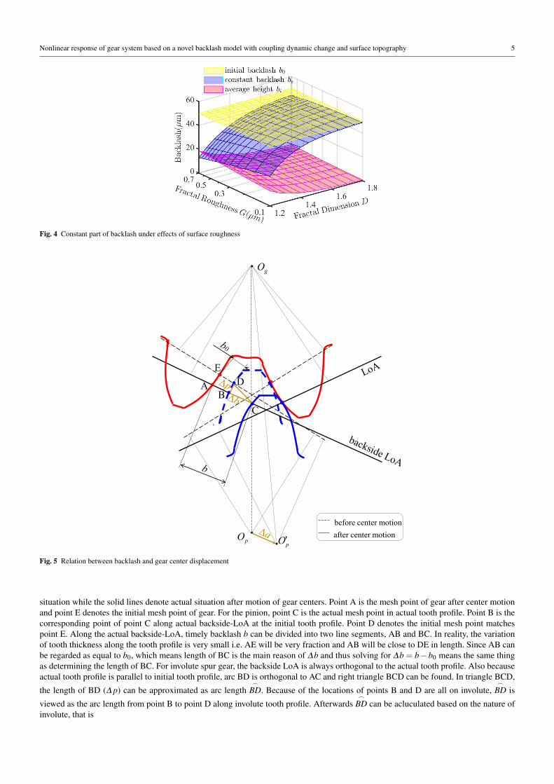
Nonlinear response of gear system based on a novel backlash model with coupling dynamic change and surface topography 5
Fig. 4 Constant part of backlash under effects of surface roughness
before center motion
after center motionpO
A
C
D
gO
pO′
E
B
Fig. 5 Relation between backlash and gear center displacement
situation while the solid lines denote actual situation after motion of gear centers. Point A is the mesh point of gear after center motion
and point E denotes the initial mesh point of gear. For the pinion, point C is the actual mesh point in actual tooth profile. Point B is the
corresponding point of point C along actual backside-LoA at the initial tooth profile. Point D denotes the initial mesh point matches
point E. Along the actual backside-LoA, timely backlash b can be divided into two line segments, AB and BC. In reality, the variation
of tooth thickness along the tooth profile is very small i.e. AE will be very fraction and AB will be close to DE in length. Since AB can
be regarded as equal to b0, which means length of BC is the main reason of ∆b and thus solving for ∆b = b−b0 means the same thing
as determining the length of BC. For involute spur gear, the backside LoA is always orthogonal to the actual tooth profile. Also because
actual tooth profile is parallel to initial tooth profile, arc BD is orthogonal to AC and right triangle BCD can be found. In triangle BCD,
the length of BD (∆ p) can be approximated as arc length⌢
BD. Because of the locations of points B and D are all on involute,⌢
BD is
viewed as the arc length from point B to point D along involute tooth profile. Afterwards⌢
BD can be acluculated based on the nature of
involute, that is
6 Xin Yu et al.
⌢BD =
∫ βc
β0
RPbβdβ=RPb
2(β 2
c −β 20 ) (7)
Herein RPb denotes the radius of base circle of pinion, β is the rolling angle which equals the sum of evolving angle and pressure angle
that decided by β = tanα . The subscript 0, c here is corresponding to initial point and actual point.
Subsequently, ∆ p i.e. length of side BD can be derived as ∆ p ≈
⌢BD. Back to right triangles BCD, where motion between points C
and D mainly comes from overall movement caused by the shift of the center. Therefore, the length of the hypotenuse CD equals the
motional distance of gear center i.e. ∆a. Afterwards, the value can be obtained by the Pythagorean theorem and Eq. (6) can be proved.
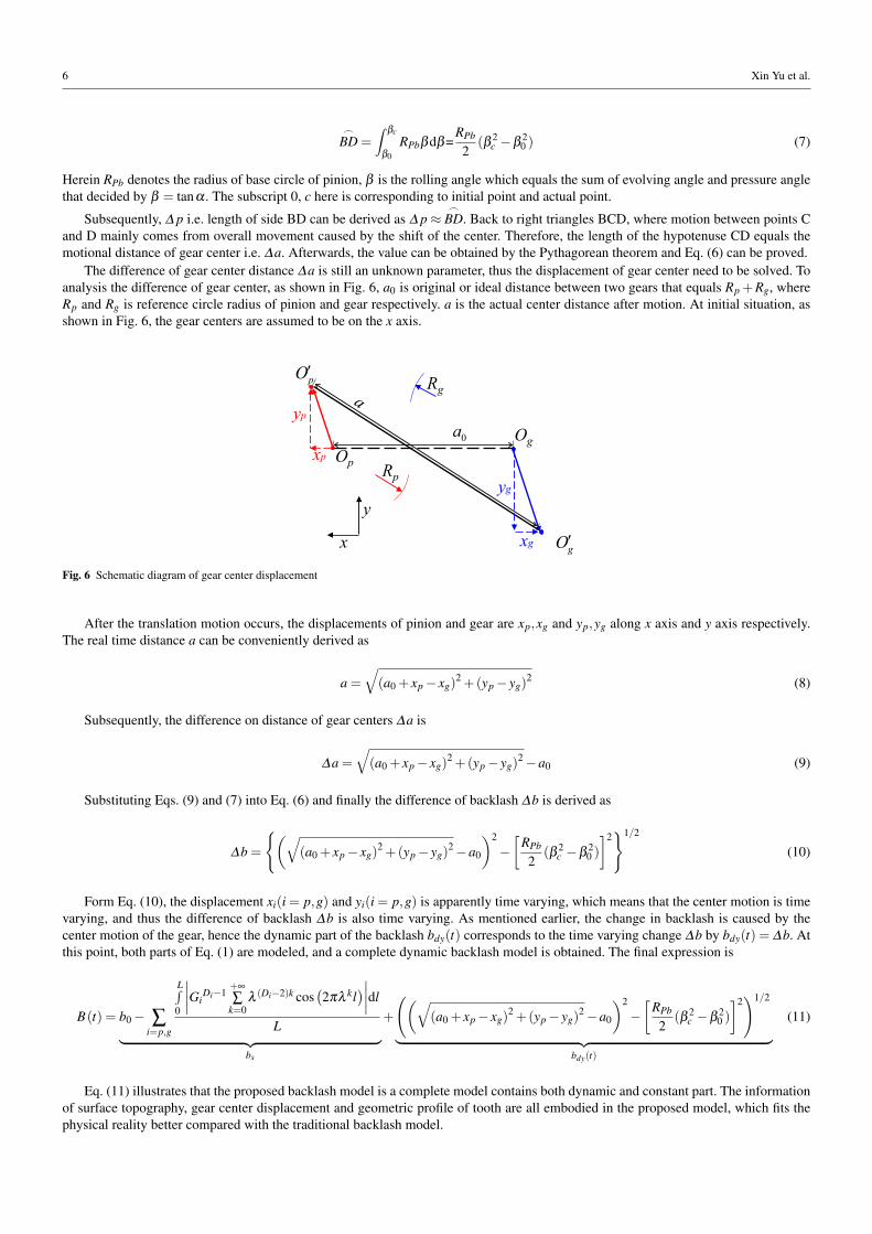
The difference of gear center distance ∆a is still an unknown parameter, thus the displacement of gear center need to be solved. To
analysis the difference of gear center, as shown in Fig. 6, a0 is original or ideal distance between two gears that equals Rp +Rg, where
Rp and Rg is reference circle radius of pinion and gear respectively. a is the actual center distance after motion. At initial situation, as
shown in Fig. 6, the gear centers are assumed to be on the x axis.
Op
Og
x
y
pO′
gO′
0a
yp
xp
xg
yg
Rg
Rp
Fig. 6 Schematic diagram of gear center displacement
After the translation motion occurs, the displacements of pinion and gear are xp,xg and yp,yg along x axis and y axis respectively.
The real time distance a can be conveniently derived as
a =
√
(a0 + xp − xg)2 +(yp − yg)
2(8)
Subsequently, the difference on distance of gear centers ∆a is
∆a =
√
(a0 + xp − xg)2 +(yp − yg)
2−a0 (9)
Substituting Eqs. (9) and (7) into Eq. (6) and finally the difference of backlash ∆b is derived as
∆b =
{(√
(a0 + xp − xg)2 +(yp − yg)
2−a0
)2
−
[RPb
2(β 2
c −β 20 )
]2}1/2
(10)
Form Eq. (10), the displacement xi(i = p,g) and yi(i = p,g) is apparently time varying, which means that the center motion is time
varying, and thus the difference of backlash ∆b is also time varying. As mentioned earlier, the change in backlash is caused by the
center motion of the gear, hence the dynamic part of the backlash bdy(t) corresponds to the time varying change ∆b by bdy(t) = ∆b. At
this point, both parts of Eq. (1) are modeled, and a complete dynamic backlash model is obtained. The final expression is
B(t) = b0 − ∑i=p,g
L∫
0
∣∣∣∣Gi
Di−1+∞
∑k=0
λ (Di−2)k cos(2πλ kl
)∣∣∣∣dl
L︸ ︷︷ ︸
bs
+
((√
(a0 + xp − xg)2 +(yp − yg)
2−a0
)2
−
[RPb
2(β 2
c −β 20 )
]2)1/2
︸ ︷︷ ︸
bdy(t)
(11)
Eq. (11) illustrates that the proposed backlash model is a complete model contains both dynamic and constant part. The information
of surface topography, gear center displacement and geometric profile of tooth are all embodied in the proposed model, which fits the
physical reality better compared with the traditional backlash model.
Nonlinear response of gear system based on a novel backlash model with coupling dynamic change and surface topography 7
pO gO
pinion gear
pxk
pyk
pxc
pyc
gxk
gxc
gykgyc
x
y
pω
gω
Fig. 7 Dynamic model of gear pair with dynamic backlash
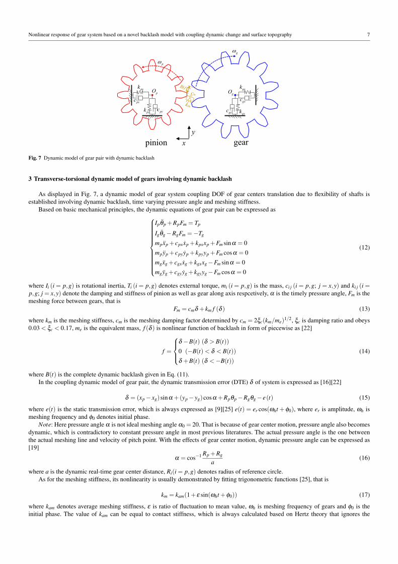
3 Transverse-torsional dynamic model of gears involving dynamic backlash
As displayed in Fig. 7, a dynamic model of gear system coupling DOF of gear centers translation due to flexibility of shafts is
established involving dynamic backlash, time varying pressure angle and meshing stiffness.
Based on basic mechanical principles, the dynamic equations of gear pair can be expressed as
Ipθp +RpFm = Tp
Igθg −RgFm =−Tg
mpxp + cpxxp + kpxxp +Fm sinα = 0
mpyp + cpyyp + kpyyp +Fm cosα = 0
mgxg + cgxxg + kgxxg −Fm sinα = 0
mgyg + cgyyg + kgyyg −Fm cosα = 0
(12)
where Ii (i = p,g) is rotational inertia, Ti (i = p,g) denotes external torque, mi (i = p,g) is the mass, ci j (i = p,g; j = x,y) and ki j (i =p,g; j = x,y) denote the damping and stiffness of pinion as well as gear along axis respcetively, α is the timely pressure angle, Fm is the
meshing force between gears, that is
Fm = cmδ + km f (δ ) (13)
where km is the meshing stiffness, cm is the meshing damping factor determined by cm = 2ξc(km/me)1/2, ξc is damping ratio and obeys
0.03 < ξc < 0.17, me is the equivalent mass, f (δ ) is nonlinear function of backlash in form of piecewise as [22]
f =
δ −B(t) (δ > B(t))
0 (−B(t)< δ < B(t))
δ +B(t) (δ <−B(t))
(14)
where B(t) is the complete dynamic backlash given in Eq. (11).
In the coupling dynamic model of gear pair, the dynamic transmission error (DTE) δ of system is expressed as [16][22]
δ = (xp − xg)sinα +(yp − yg)cosα +Rpθp −Rgθg − e(t) (15)
where e(t) is the static transmission error, which is always expressed as [9][25] e(t) = er cos(ωht + φ0), where er is amplitude, ωh is
meshing frequency and φ0 denotes initial phase.
Note: Here pressure angle α is not ideal meshing angle α0 = 20. That is because of gear center motion, pressure angle also becomes
dynamic, which is contradictory to constant pressure angle in most previous literatures. The actual pressure angle is the one between
the actual meshing line and velocity of pitch point. With the effects of gear center motion, dynamic pressure angle can be expressed as
[19]
α = cos−1 Rp +Rg
a(16)
where a is the dynamic real-time gear center distance, Ri(i = p,g) denotes radius of reference circle.
As for the meshing stiffness, its nonlinearity is usually demonstrated by fitting trigonometric functions [25], that is
km = kam(1+ ε sin(ωht +φ0)) (17)
where kam denotes average meshing stiffness, ε is ratio of fluctuation to mean value, ωh is meshing frequency of gears and φ0 is the
initial phase. The value of kam can be equal to contact stiffness, which is always calculated based on Hertz theory that ignores the
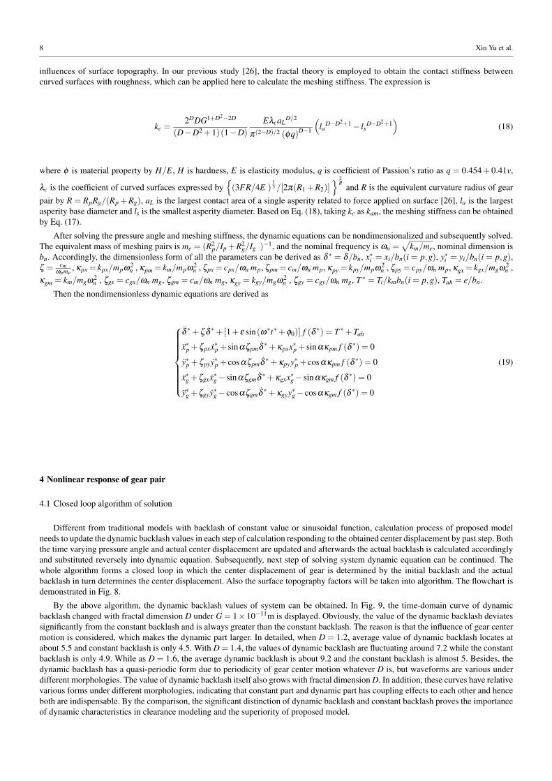
8 Xin Yu et al.
influences of surface topography. In our previous study [26], the fractal theory is employed to obtain the contact stiffness between
curved surfaces with roughness, which can be applied here to calculate the meshing stiffness. The expression is
kc =2DDG1+D2
−2D
(D−D2 +1)(1−D)
EλcaLD/2
π(2−D)/2 (φq)D−1
(
laD−D2+1
− lsD−D2+1
)
(18)
where φ is material property by H/E, H is hardness, E is elasticity modulus, q is coefficient of Passion’s ratio as q = 0.454+ 0.41v,
λc is the coefficient of curved surfaces expressed by{
(3FR/4E )13 /[2π(R1 +R2)]
} 2R
and R is the equivalent curvature radius of gear
pair by R = RpRg/(Rp +Rg), aL is the largest contact area of a single asperity related to force applied on surface [26], la is the largest
asperity base diameter and ls is the smallest asperity diameter. Based on Eq. (18), taking kc as kam, the meshing stiffness can be obtained
by Eq. (17).
After solving the pressure angle and meshing stiffness, the dynamic equations can be nondimensionalized and subsequently solved.
The equivalent mass of meshing pairs is me = (R2p/Ip +R2
g/Ig )−1, and the nominal frequency is ωn =√
km/me, nominal dimension is
bn. Accordingly, the dimensionless form of all the parameters can be derived as δ ∗ = δ/bn, x∗i = xi/bn(i = p,g), y∗i = yi/bn(i = p,g),ζ = cm
ωnme, κpx = kpx/mpω2
n , κpm = km/mpω2n , ζpx = cpx/ωn mp, ζpm = cm/ωn mp, κpy = kpy/mpω2
n , ζpy = cpy/ωn mp, κgx = kgx/mgω2n ,
κgm = km/mgω2n , ζgx = cgx/ωn mg, ζgm = cm/ωn mg, κgy = kgy/mgω2
n , ζgy = cgy/ωn mg, T ∗ = Ti/kmbn(i = p,g), Tah = e/bn.
Then the nondimensionless dynamic equations are derived as
δ ∗+ζ δ ∗+[1+ ε sin(ω∗t∗+φ0)] f (δ ∗) = T ∗+Tah
x∗p +ζpxx∗p + sinαζpmδ ∗+κpxx∗p + sinακpm f (δ ∗) = 0
y∗p +ζpyy∗p + cosαζpmδ ∗+κpyy∗p + cosακpm f (δ ∗) = 0
x∗g +ζgxx∗g − sinαζgmδ ∗+κgxx∗g − sinακgm f (δ ∗) = 0
y∗g +ζgyy∗g − cosαζgmδ ∗+κgyy∗g − cosακgm f (δ ∗) = 0
(19)
4 Nonlinear response of gear pair
4.1 Closed loop algorithm of solution
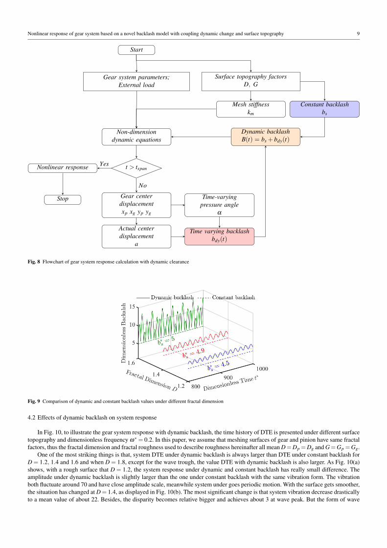
Different from traditional models with backlash of constant value or sinusoidal function, calculation process of proposed model
needs to update the dynamic backlash values in each step of calculation responding to the obtained center displacement by past step. Both
the time varying pressure angle and actual center displacement are updated and afterwards the actual backlash is calculated accordingly
and substituted reversely into dynamic equation. Subsequently, next step of solving system dynamic equation can be continued. The
whole algorithm forms a closed loop in which the center displacement of gear is determined by the initial backlash and the actual
backlash in turn determines the center displacement. Also the surface topography factors will be taken into algorithm. The flowchart is
demonstrated in Fig. 8.
By the above algorithm, the dynamic backlash values of system can be obtained. In Fig. 9, the time-domain curve of dynamic
backlash changed with fractal dimension D under G = 1×10⁻¹¹m is displayed. Obviously, the value of the dynamic backlash deviates
significantly from the constant backlash and is always greater than the constant backlash. The reason is that the influence of gear center
motion is considered, which makes the dynamic part larger. In detailed, when D = 1.2, average value of dynamic backlash locates at
about 5.5 and constant backlash is only 4.5. With D = 1.4, the values of dynamic backlash are fluctuating around 7.2 while the constant
backlash is only 4.9. While as D = 1.6, the average dynamic backlash is about 9.2 and the constant backlash is almost 5. Besides, the
dynamic backlash has a quasi-periodic form due to periodicity of gear center motion whatever D is, but waveforms are various under
different morphologies. The value of dynamic backlash itself also grows with fractal dimension D. In addition, these curves have relative
various forms under different morphologies, indicating that constant part and dynamic part has coupling effects to each other and hence
both are indispensable. By the comparison, the significant distinction of dynamic backlash and constant backlash proves the importance
of dynamic characteristics in clearance modeling and the superiority of proposed model.
Nonlinear response of gear system based on a novel backlash model with coupling dynamic change and surface topography 9
Start
Gear system parameters;
External load
Surface topography factors
D, G
Mesh stiffness
km
Constant backlash
bs
Non-dimension
dynamic equations
t > tspan
Gear center
displacement
xp xg yp yg
Actual center
displacement
a
Time-varying
pressure angle
α
Time varying backlash
bdy(t)
Dynamic backlash
B(t) = bs + bdy(t)
Nonlinear response
Stop
No
Yes
Fig. 8 Flowchart of gear system response calculation with dynamic clearance
Fig. 9 Comparison of dynamic and constant backlash values under different fractal dimension
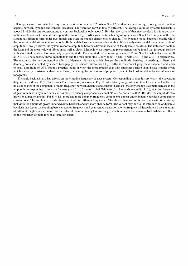
4.2 Effects of dynamic backlash on system response
In Fig. 10, to illustrate the gear system response with dynamic backlash, the time history of DTE is presented under different surface
topography and dimensionless frequency ω∗ = 0.2. In this paper, we assume that meshing surfaces of gear and pinion have same fractal
factors, thus the fractal dimension and fractal roughness used to describe roughness hereinafter all mean D=Dp =Dg and G=Gp =Gg.
One of the most striking things is that, system DTE under dynamic backlash is always larger than DTE under constant backlash for
D = 1.2, 1.4 and 1.6 and when D = 1.8, except for the wave trough, the value DTE with dynamic backlash is also larger. As Fig. 10(a)
shows, with a rough surface that D = 1.2, the system response under dynamic and constant backlash has really small difference. The
amplitude under dynamic backlash is slightly larger than the one under constant backlash with the same vibration form. The vibration
both fluctuate around 70 and have close amplitude scale, meanwhile system under goes periodic motion. With the surface gets smoother,
the situation has changed at D = 1.4, as displayed in Fig. 10(b). The most significant change is that system vibration decrease drastically
to a mean value of about 22. Besides, the disparity becomes relative bigger and achieves about 3 at wave peak. But the form of wave
10 Xin Yu et al.
still keeps a same form, which is very similar to situation at D = 1.2. When D = 1.6, as demonstrated in Fig. 10(c), great distinction
appears between dynamic and constant backlash. The vibration form is totally different. The average value of dynamic backlash is
about 12 while the one corresponding to constant backlash is only about 7. Besides, the curve of dynamic backlash is a four-periodic
motion while constant model is quasi-periodic motion. Fig. 10(d) shows the time history of system with D = 1.8 i.e. very smooth. The
system has different form under two models and even the chaotic characteristics change. The dynamic model becomes chaotic while
the constant model still maintains periodic. Both models have same mean value at about 0 but the dynamic model has a larger scale of
amplitude. Through above, the system response amplitude becomes different because of the dynamic backlash. The influences contain
the form and the mean value of vibration as well as chaos. Meanwhile, an interesting phenomenon can be found that for rough surface
with less initial backlash has conversely large amplitude. The amplitude of vibration gets about 115 for D = 1.2, while decrease to 30
at D = 1.4. The tendency shows monotonous and the max amplitude is only about 18 and 16 with D = 1.6 and D = 1.8 respectively.
The reason maybe the compensation effects of dynamic clearance, which changes the amplitude. Besides, the meshing stiffness and
damping are also affected by surface topography. For smooth surface with high stiffness, the contact property is enhanced and leads
to small amplitude of DTE. From a practical point of view, the more precise gear with smoother surface should have smaller error,
which is exactly consistent with our conclusion, indicating the correctness of proposed dynamic backlash model under the influence of
topography.
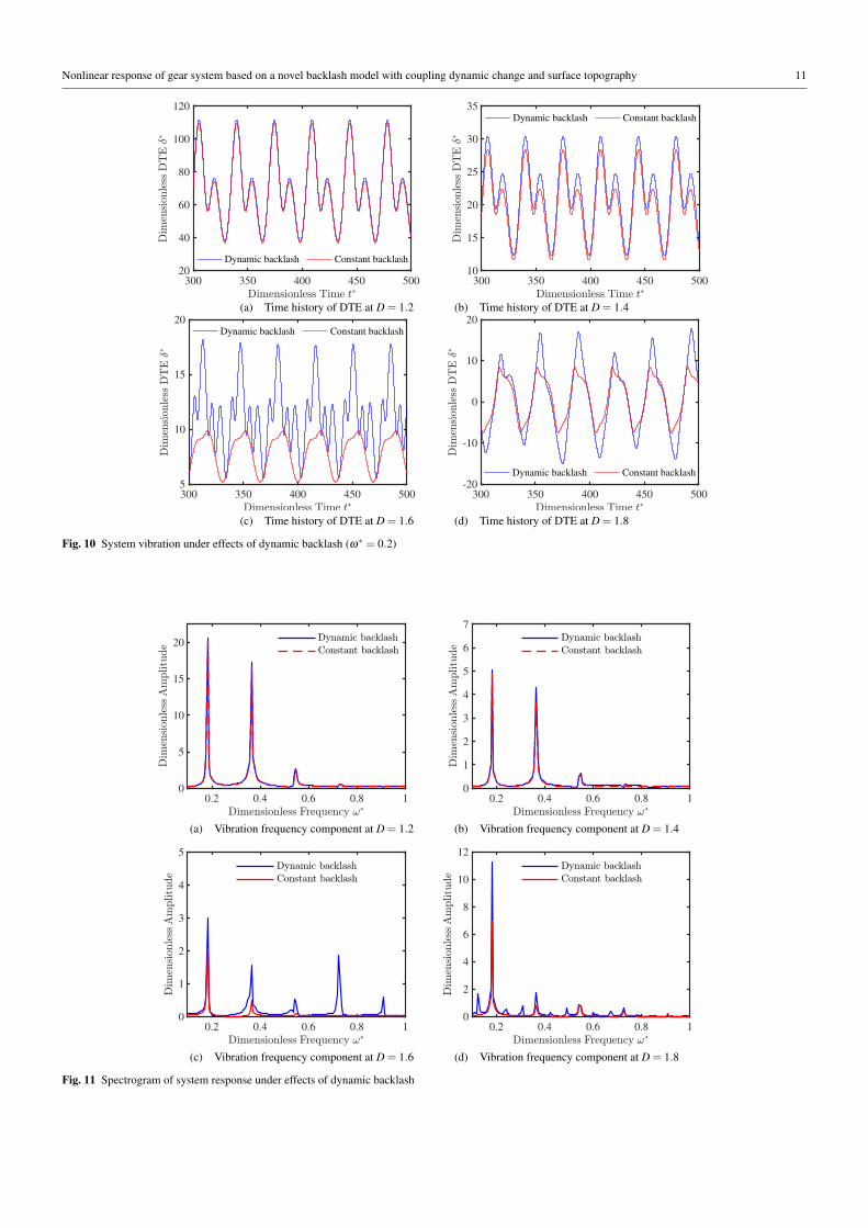
Dynamic backlash also has effects on the vibration frequency of gear system. Corresponding to time history charts, the spectrum
diagram derived from FFT (Fast Fourier Transformation) is shown in Fig. 11. At relatively rough situation D = 1.2 and D = 1.4, there is
no clear change at the component of main frequency between dynamic and constant backlash, the only change is a small increase in the
amplitude corresponding to the main frequency at ω∗ = 0.2 and ω∗ = 0.4. While for D= 1.6, as shown in Fig. 11(c), vibration frequency
of gear system with dynamic backlash has more frequency components at about ω∗ = 0.59 and ω∗ = 0.75. Besides, the amplitude also
grows by a greater amount. For D = 1.8, more and more complex frequency components appear under dynamic backlash compared to
constant one. The amplitude has also become larger for different frequencies. The above phenomenon is consistent with time history
that vibration amplitude grows under dynamic backlash and has more chaotic form. The variant may due to the introduction of dynamic
backlash that forces the coupling between torsion frequency and gear center translation motion frequency. Meanwhile, all the situations
of different roughness keep same that the value of main frequency has no change, which indicates that dynamic backlash has no effects
on the frequency of main torsional vibration itself.
Nonlinear response of gear system based on a novel backlash model with coupling dynamic change and surface topography 11
300 350 400 450 50020
40
60
80
100
120
Dynamic backlash Constant backlash
300 350 400 450 50010
15
20
25
30
35Dynamic backlash Constant backlash
(a) Time history of DTE at D = 1.2 (b) Time history of DTE at D = 1.4
300 350 400 450 5005
10
15
20Dynamic backlash Constant backlash
300 350 400 450 500-20
-10
0
10
20
Dynamic backlash Constant backlash
(c) Time history of DTE at D = 1.6 (d) Time history of DTE at D = 1.8
Fig. 10 System vibration under effects of dynamic backlash (ω∗ = 0.2)
0.2 0.4 0.6 0.8 1
0
5
10
15
20
0.2 0.4 0.6 0.8 1
0
1
2
3
4
5
6
7
(a) Vibration frequency component at D = 1.2 (b) Vibration frequency component at D = 1.4
0.2 0.4 0.6 0.8 1
0
1
2
3
4
5
0.2 0.4 0.6 0.8 1
0
2
4
6
8
10
12
(c) Vibration frequency component at D = 1.6 (d) Vibration frequency component at D = 1.8
Fig. 11 Spectrogram of system response under effects of dynamic backlash
12 Xin Yu et al.
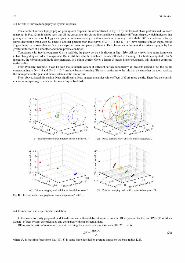
4.3 Effects of surface topography on system response
The effects of surface topography on gear system response are demonstrated in Fig. 12 by the form of phase portraits and Poincare
mapping. In Fig. 12(a), it can be seen that all the curves are thin closed lines and have completely different shapes, which indicates that
gear system under all morphology undergoes periodic motion at given dimensionless frequency. But both the DTE and relative velocity
shows decreasing trend with D. There is another phenomenon that curves of D = 1.2 and D = 1.4 have relative similar shape, but as
D gets larger i.e. a smoother surface, the shape becomes completely different. This phenomenon declares that surface topography has
greater influences at a smoother and more precise condition.
Comparing with fractal roughness G as a variable, the phase portraits is shown in Fig. 12(b). All the curves have same form even
G has changed by an order of magnitude. But G still has effects, which are mainly reflected in the range of vibration amplitude. As G
increases, the vibration amplitude also increases, in a minor degree. Given a larger G means higher roughness, this situation conforms
to the reality.
From Poincare mapping, it can be seen that although system at different surface topography all presents periodic, but the points
corresponding to D = 1.8 and G = 1×10⁻¹²m show better clustering. This also conforms to the rule that the smoother the tooth surface,
the more precise the gear and more systematic the motion are.
From above, fractal dimension D has significant effects on gear dynamics while effects of G are more gentle. Therefore the consid-
eration of morphology is essential for modeling of backlash.
(a) Phase portraits under different fractal dimension D (b) Phase portraits under different fractal roughness G
(c) Poincare mapping under different fractal dimension D (d) Poincare mapping under different fractal roughness G
Fig. 12 Effects of surface topography on system response (ω∗ = 0.31)
4.4 Comparison and experimental validation
In this work, to verify proposed model and compare with available literatures, both the DF (Dynamic Factor) and RMS (Root Mean
Square) of gear system are calculated and compared with experimental data.
DF means the ratio of maximum dynamic meshing force and statics root stresses [10][25], that is
DF =max[Fm]
Fs
(20)
where Fm is meshing force from Eq. (13), Fs is static force decided by average torque on the base radius [22].

Nonlinear response of gear system based on a novel backlash model with coupling dynamic change and surface topography 13
The compared model is Chen’s model based on fractal backlash from Ref. [25] and Kahraman’s model that contains classic constant
backlash from Ref. [10]. The experimental test rig and main parameters which can be found in Ref. [10] are presented in Tab. 1.
Table 1 Main DF experimental parameters [10]
Name Value
Teeth number 25/25
Inertia(kg/m2) 1.15×10⁻³
Equivalent Mass(kg) 0.23
Rp,Rg(m) 0.094
km(N/m) 3×10⁸
T (N*m) 107.8
bh(m) 1×10⁻³
ξ 0.1
Tah 0.019
To make proposed model comparable, the effects of surface topography are eliminated to accord with the actual experimental
parameters and the main distinction lays on the dynamic characteristics of backlash. The result is displayed in Fig. 13. All the models
have same trend with experimental data. Proposed model has obvious advantage of approaching experimental data at relative low
(0.2˜0.8) and high frequency (0.9˜1.2). Besides, the proposed model has the most approximation at the discontinue jump action at
amplitude from both jump frequency and amplitude aspect. By contrast, predicted values of Chen’ model and Kahraman’s model both
are much bigger than the experimental data. Since the difference comes from backlash model, the proposed dynamic backlash can be
validated and its superiority is also demonstrated.
Fig. 13 Comparison of DF values calculated by proposed model and experimental data as well as other models
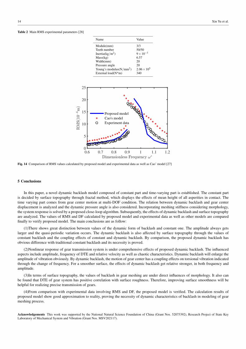
RMS is the root mean square of the amplitude belonging to the different harmonic levels of DTE, which can be expressed as [27]
RMS =
√n
∑i=1
A2i /n (21)
Herein Ai denotes the amplitude of ith harmonic, n is the number of harmonics taken into account.
The compared model is Cao’s model that based on force-dependent meshing stiffness with constant backlash from Ref. [27] and
Kahraman’s experimental data from Ref. [28]. The test rig in Ref. [28] is a four square gear dynamic setup contains a precision gear
pair. By accelerometers mounted tangentially to gear, the torsional vibration amplitude can be measured. Since Cao’s model is based on
stiffness and ignores the effects of backlash, the emphasis of comparison can focus more on the influence of the presence or absence of
backlash. The experimental parameters are presented in Tab. 2 [28].
Overall, calculation values of proposed model have a better approach as illustrated in Fig. 14. Cao’s model has an obvious tendency
that is larger than the experimental data. While the proposed model shows a slight fluctuation around the experimental data. Meanwhile,
the predicted values of proposed model are very close to the experiment data at low frequency (0.6˜0.8). By the results, the correctness
and superiority of proposed model can be proved.
14 Xin Yu et al.
Table 2 Main RMS experimental parameters [28]
Name Value
Module(mm) 3/3
Teeth number 50/50
Inertia(kg/m2) 9×10⁻³
Mass(kg) 6.57
Width(mm) 20
Pressure angle 20
Young’s modulus(N/mm2) 2.06×10⁵
External load(N*m) 340
0.6 0.7 0.8 0.9 1 1.1 1.20
5
10
15
20
25
Proposed model
Cao's model
Experiment data
Fig. 14 Comparison of RMS values calculated by proposed model and experimental data as well as Cao’ model [27]
5 Conclusions
In this paper, a novel dynamic backlash model composed of constant part and time-varying part is established. The constant part
is decided by surface topography through fractal method, which displays the effects of mean height of all asperities in contact. The
time varying part comes from gear center motion at multi-DOF condition. The relation between dynamic backlash and gear center
displacement is analyzed and the dynamic pressure angle is also considered. Incorporating meshing stiffness considering morphology,
the system response is solved by a proposed close-loop algorithm. Subsequently, the effects of dynamic backlash and surface topography
are analyzed. The values of RMS and DF calculated by proposed model and experimental data as well as other models are compared
finally to verify proposed model. The main conclusions are as follow:
(1)There shows great distinction between values of the dynamic form of backlash and constant one. The amplitude always gets
larger and the quasi-periodic variation occurs. The dynamic backlash is also affected by surface topography through the values of
constant backlash and the coupling effects of constant and dynamic backlash. By comparison, the proposed dynamic backlash has
obvious difference with traditional constant backlash and its necessity is proved.
(2)Nonlinear response of gear transmission system is under comprehensive effects of proposed dynamic backlash. The influenced
aspects include amplitude, frequency of DTE and relative velocity as well as chaotic characteristics. Dynamic backlash will enlarge the
amplitude of vibration obviously. By dynamic backlash, the motion of gear center has a coupling effects on torsional vibration indicated
through the change of frequency. For a smoother surface, the effects of dynamic backlash get relative stronger, in both frequency and
amplitude.
(3)In terms of surface topography, the values of backlash in gear meshing are under direct influences of morphology. It also can
be found that DTE of gear system has positive correlation with surface roughness. Therefore, improving surface smoothness will be
helpful for realizing precise transmission of gears.
(4)From comparison with experimental data involving RMS and DF, the proposed model is verified. The calculation results of
proposed model show good approximation to reality, proving the necessity of dynamic characteristics of backlash in modeling of gear
meshing process.
Acknowledgements This work was supported by the National Natural Science Foundation of China (Grant Nos. 52075392), Research Project of State Key
Laboratory of Mechanical System and Vibration (Grant Nos. MSV202117).

Nonlinear response of gear system based on a novel backlash model with coupling dynamic change and surface topography 15
Compliance with ethical standards
Data availability statements
All data generated or analysed during this study are included in this published article.
Conflict of interest
The authors declare that they have no conflict of interest.
List of symbols
Alphabets
a Actual gear center distance
a0 Initial gear center distance
Ai Amplitude of ith harmonic
aL Largest contact area of single asperity
B(t) The complete gear backlash
b0 Initial gear backlash
bi Effective mean value of asperity height
bn,x∗,y∗,T ∗,Tah Dimensionless dynamic parameters of gear system
bs The constant part of gear backlash
bdy(t) The time-variant part of gear backlash
cm Meshing damping
D Fractal dimension
E Elasticity modulus
f (δ ) Backlash function
Fm Meshing force
Fs Static force
G Fractal roughness
H Hardness
Ii(i = p,g) Rotational inertia
k Level of asperity
kam Average stiffness
kc Contact stiffness
ki j(i = p,g; j = x,y) Damping coefficient of bearing
km Meshing stiffness
L Length of contact region
l Length scale of asperity
la Largest base diameter of single asperity
ls Smallest base diameter of single asperity
me Equivalent mass of gear pair
mi(i = p,g) Mass
mi(i = p,g) Stiffness coefficient
mi j(i = p,g; j = x,y) Damping coefficient of bearing
n The number of harmonics taken into account
q Coefficient of Passion’s ratio
Ri(i = p,g) Radius of reference circle
Rpb Radius of base circle of pinion
Ti(i = p,g) External torque
v Passion’s ratio
z(l) Profile of surface morphology
z(t) Fractal backlash
Zp, Zg Profile of asperities
Greek symbols
α Actual pressure angle
β Rolling angle
∆a Change of gear center distance
∆b Change of backlash

16 Xin Yu et al.
∆ p Defined in Fig. 5
δ Dynamic transmission error
λ Surface coeffcient of frequency destiny
λc Coefficient of curved surface
ωh Meshing frequency
ωn Natural frequency of gear
φ Material property
ε Ratio of stiffness fluctuation
ξ Damping ratio
ξ ,δ ∗,κ Dimensionless dynamic parameters of gear system
Subscript
0 Initial
c Actual
g Gear
p Pinion
x x axis
y y axis
References
1. HF Xiao, XJ Zhou, J Liu, and YM Shao. Vibration transmission and energy dissipation through the gear-shaft-bearing-housing
system subjected to impulse force on gear. Measurement, 102:64–79, 2017.
2. LC Sheng, W Li, YQ Wang, MB Fan, and XF Yang. Nonlinear dynamic analysis and chaos control of multi-freedom semi-direct
gear drive system in coal cutters. Mechanical Systems and Signal Processing, 116:62–77, 2019.
3. WN Yu, C.K Mechefske, and M Timusk. A new dynamic model of a cylindrical gear pair with localized spalling defects. Nonlinear
Dynamics, 91:2077–2095, 2018.
4. V Onishchenko. Investigation of tooth wears from scuffing of heavy duty machine spur gears. Mech Mach Theory, 83:38–55, 2015.
5. L Walha, T Fakhfakh, and M Haddar. Nonlinear dynamics of a two-stage gear system with mesh stiffness fluctuation, bearing
flexibility and backlash. Mechanism and Machine Theory, 44(5):1058–1069, 2009.
6. H Moradi and H Salarieh. Analysis of nonlinear oscillations in spur gear pairs with approximated modelling of backlash nonlin-
earity. Mechanism and Machine Theory, 51:14–31, 2012.
7. A Saghafi and A Farshidianfar. An analytical study of controlling chaotic dynamics in a spur gear system. Mechanism and Machine
Theory, 96:179–191, 2016.
8. YS Xiong, K Huang, FW Xu, Y Yi, M Sang, and H Zhai. Research on the influence of backlash on mesh stiffness and the nonlinear
dynamics of spur gears. Applied Sciences-Basel, 9(5):1029, 2019.
9. A Kahraman and R Singh. Non-linear dynamics of a spur gear pair. Journal of Sound and Vibration, 142(1):49–75, 1990.
10. A Kahraman and R Singhr. Interactions between time-varying mesh stiffness and clearance non-linearities in a geared system.
Journal of Sound and Vibration, 146(1):135–156, 1991.
11. S Theodossaades and S Natsiavas. Non-linear dynamics of gear-pair systems with periodic stiffness and backlash. Journal of Sound
and Vibration, 229(2):287–310, 2000.
12. JW Lu, H Chen, FL Zeng, AF Vakakis, and LA Bergman. Influence of system parameters on dynamic behavior of gear pair with
stochastic backlash. Meccanica, 49(2):429–440, 2014.
13. HT Chen, XH Wang, HC Gao, and F Yan. Dynamic characteristics of wind turbine gear transmission system with random wind
and the effect of random backlash on system stability. Proc IMechE Part C: Journal of Mechanical Engineering Science, 0:1–8,
2016.
14. Q Chen, Y Ma, S Huang, and H Zhai. Research on gears’ dynamic performance influenced by gear backlash based on fractal
theory. Applied Surface Science, 313:325–332, 2014.
15. K Huang, ZB Chen, YS Xiong, GZ Han, and LY Li. Bifurcation and chaos analysis of a spur gear pair system with fractal gear
backlash. Chaos, Solitons and Fractals, 142:110387, 2021.
16. SY Chen, JY Tang, CW Luo, and QB Wang. Nonlinear dynamic characteristics of geared rotor bearing systems with dynamic
backlash and friction. Mechanism and Machine Theory, 46:466–478, 2011.
17. TF Yang, SZ Yan, and ZY Han. Nonlinear model of space manipulator joint considering time-variant stiffness and backlash.
Journal of Sound and Vibration, 341:246–259, 2015.
18. YG Li, Tn Chen, and Xp Wang. Non-linear dynamics of gear pair with dynamic backlash subjected to combined internal and
external periodic excitations. Journal of Vibration and Control, 22(6):1693–1703, 2014.
19. H Liu, C Zhang, Cl Xiang, and C Wang. Tooth profile modification based on lateral-torsional-rocking coupled nonlinear dynamic
model of gear system. Mechanism and Machine Theory, 105:606–619, 2016.
20. SY Wang and RP Zhu. Theoretical investigation of the improved nonlinear dynamic model for star gearing system in gtf gearbox
based on dynamic meshing parameters. Mechanism and Machine Theory, 156:104108, 2021.

Nonlinear response of gear system based on a novel backlash model with coupling dynamic change and surface topography 17
21. GJ Wang, L Chen, L Yu, and SD Zou. Research on the dynamic transmission error of a spur gear pair with eccentricities by finite
element method. Mechanism and Machine Theory, 109:1–13, 2017.
22. Y Yi, K Huang, YS Xiong, and M Sang. Nonlinear dynamic modelling and analysis for a spur gear system with time-varying
pressure angle and gear backlash. Mechanical Systems and Signal Processing, 132:18–34, 2019.
23. JF Shi, XF Gou, and LY Zhu. Calculation of time-varying backlash for an involute spur gear pair. Mechanism and Machine Theory,
152:103956, 2020.
24. A Majumdar and B Bhushan. Fractal model of elastic-plastic contact between rough surfaces. Journal of Tribology, 113(1):1–11,
1991.
25. Q Chen, Y Ma, S Huang, and H Zhai. An improved nonlinear dynamic model of gear pair with tooth surface microscopic features.
Nonlinear Dynamics, 96:1915–1934, 2019.
26. X Yu, YY Sun, D Zhao, and SJ Wu. A revised contact stiffness model of rough curved surfaces based on the length scale. Tribology
International, 164:107206, 2021.
27. Z Cao, ZG Chen, and HJ Jiang. Nonlinear dynamics of a spur gear pair with force-dependent mesh stiffness. Nonlinear Dynamics,
99:1227–1241, 2020.
28. A Kahraman and GW Blankenship. Experiments on nonlinear dynamic behavior of an oscillator with clearance and periodically
time-varying parameters. Journal of Applied Mechanics, 64:217–226, 1997.