Nonlinear dynamic response analysis of a long-span ...
12
DOI: http://dx.doi.org/10.12989/imm.2010.3.4.309
Transcript of Nonlinear dynamic response analysis of a long-span ...
Interaction and Multiscale Mechanics, Vol. 3, No. 4 (2010) 309-320 309
Nonlinear dynamic response analysis of a long-span suspension bridge under running train and turbulent wind
S.Q. Wang*, H. Xia, W.W. Guo and N. Zhang
School of Civil Engineering, Beijing Jiaotong University, Beijing 100044, China
(Received July 27, 2010, Accepted October 22, 2010)
Abstract. With taking the geometric nonlinearity of bridge structure into account, a framework ispresented for predicting the dynamic responses of a long-span suspension bridge subjected to runningtrain and turbulent wind. The nonlinear dynamic equations of the coupled train-bridge-wind system areestablished, and solved with the Newmark numerical integration and direct interactive method. Thecorresponding linear and nonlinear processes for solving the system equation are described, and thecorresponding computer codes are written. The proposed framework is then applied to a schemed long-span suspension bridge with the main span of 1120 m. The whole histories of the train passing throughthe bridge under turbulent wind are simulated, and the dynamic responses of the bridge are obtained. Theresults demonstrate that the geometric nonlinearity does not influence the variation tendency of the bridgedisplacement histories, but the maximum responses will be changed obviously; the lateral displacement ofbridge are more sensitive to the wind than the vertical ones; compared with wind velocity, train speedaffects the vertical maximum responses a little more clearly.
Keywords: geometric nonlinearity; suspension bridge; dynamic response; train; wind.
1. Introduction
With the rapid development of economy and techniques, and to meet the community needs for
safe and efficient transportation, more and more long-span bridges carrying railway have been being
built throughout the world.
Generally, the long-span bridges are probably built in wind prone area, and exhibit special
characteristics such as high flexibility and low structural damping. The dynamic interaction between
bridges and trains is an important problem to be solved for bridge design. When the train running
on a long-span suspension bridge, the bridge will experience considerable vibration due to both
moving train and turbulent winds, which may bring fatigue failures to the structures, or even
completely destroy the bridge, and the vibration of the bridge may in turn affect the running safety
of trains and the comfort of passengers (Guo and Xu 2006). Therefore, the safety of high speed
train running on an oscillating long-span suspension bridge under turbulent wind has become a topic
of increasing concern in recent years. This presents a complicated dynamic interaction problem
* Corresponding author, Doctor Postgraduate Student, E-mail: [email protected]
DOI: http://dx.doi.org/10.12989/imm.2010.3.4.309

310 S.Q. Wang, H. Xia, W.W. Guo and N. Zhang
between the bridge, the train and the turbulent wind. This problem has been noticed and studied by
researchers in China and abroad (Flýba 1996, Guo and Xia 2004, Yang 2008).
In the previous studies, Xu et al. (2003) presented a framework for predicting the dynamic
response of the Tsing Ma suspension bridge to high winds and running trains, in which the trains
run inside the bridge deck of a closed cross section and there was no wind force directly acting on
the trains, and later in another paper (Xu and Zhang 2004), in which the dynamic responses of
cable-stayed bridge and train in cross wind are obtained, but the study focused on the comparison of
dynamic responses with and without wind load, and train speed kept constant. Based on the modal
superposition technique, Xia et al. (2008) established a dynamic model of wind-train-bridge system,
the dynamic response of the schemed Tianxingzhou Yangtze River bridge under wind actions was
simulated and the running safety and stability indices of the train vehicles were obtained, but it was
in linear analysis, the geometric nonlinearity of long-span suspension bridge was ignored.
The construction of the Beijing-Shanghai High-speed Railway accelerates the study of coupled
train and long-span bridge system under wind action. Guo and Zeng (2001) analysed the critical
wind speed for running trains on a schemed cable-stayed bridge that crossing the Yangze River in
Nanjing, from which the warning and closing wind speed of the bridge were obtained. Based on the
Nanjing Dashengguan Yangtze River Bridge, a 6-span arch bridge, Zhang and Xia (2009) analysed
the coupling vibration of the wind-vehicle-bridge system, the results show that the dynamic
response of bridge system increases with the wind velocity, whose sensitivity in lateral direction is
larger than that in vertical direction, and the thresholds of wind velocity versus train speed for the
ICE3 and CRH were drawn. Yang (2008) studied the aerostatic instability of cable-supported
bridges, with emphasis placed on modeling of the geometric nonlinear effects of various components
of cable-supported bridges.
This paper extends the previous work to perform a nonlinear dynamic model of the coupled wind-
train-bridge system. With taking part of the geometric nonlinearity into account, a three dimensional
finite element model is established to represent a schemed long-span suspension bridge, and another
geometric nonlinearity is considered while solving the wind-train-bridge system equations. The
whole histories of the train passing through the bridge under wind actions are simulated, and the
influences of geometric nonlinearity, wind velocity and train speed on the dynamic responses of the
long-span suspension bridge are analysed in detail.
2. Basic theory and analysis model
The dynamic analysis model of the wind-train-bridge system consists of three sub-models: the
dynamic model of a train, a long-span suspension bridge, and the wind loads on the bridge-train
system, as shown in Fig. 1.
2.1 Train model
The train model consists of several locomotives and vehicles. Each locomotive or vehicle is
composed of the car-body, bogies, wheel-sets, and the spring and damping connections between the
three components.
In order to simplify the analysis but with enough accuracy, it is supposed that the car-body, bogies
and wheel-sets in each vehicle are regarded as rigid components, neglecting their elastic

Nonlinear dynamic response analysis of a long-span suspension bridge under running train and turbulent wind 311
deformation during vibration. Five DOFs are concerned for each car body or a bogie: the lateral
displacement Y, the vertical displacement Z, the roll displacement RX, the yaw displacement RZ, and
the pitch displacement RY with respect to its mass center. A wheel-set has three DOFs: the lateral
displacement Y, the vertical displacement Z, the roll displacement RX to its mass center. Therefore,
the analysis model for each vehicle with 2-bogies and 4-axles can be modeled by a 27-DOFs
dynamic system.
2.2 Bridge model
A long suspension bridge mainly consists of bridge towers, piers, main girders, highway and
railway decks, cables, suspenders and anchorages. In this study, the suspension bridge is modeled as
a three-dimensional system using the finite element analysis software MIDAS.
In fact, the relationship between the loads and displacements of a long-span suspension bridge
structure is nonlinear. The total nonlinear characteristics chiefly come from three factors as follows
(Pan 2004, Boonyapinyo 1994, Chen 2000):
Fig. 1 Model of wind-train-bridge system

312 S.Q. Wang, H. Xia, W.W. Guo and N. Zhang
(1) The internal force effect of dead loads. To obtain the balanced state of the structure, the true
deformation should be calculated when the internal loads, dead loads and outside loads are all
applied.
(2) The sagging effect induced by combined action of cable tension and gravity. This effect can
be solved by the Ernst Equation, which is shown as
(1)
where, E is the original Young’s Modulus of the cable material; W is the unit weight of the cable
material; L is the length in the horizontal plane; A is the cross section of the cable; F is the inner
tension of the cable.
In this paper, the nonlinearity of the internal force effect and sagging effect are considered in the
process of modeling, and the large-displacement influence is analyzed through the numerical
integration process while solving the system equation, which will be introduced in detail hereinafter.
2.3 Wind load
There are three wind loads acting on the bridge: steady-state wind load, buffeting wind load and
self-excited wind load. The steady-state wind load can be calculated by the structure dimensions and
aerodynamic force coefficients from wind tunnel tests, which keeps unchanged in the whole history
of train running on the bridge. The buffeting wind load is induced by the fluctuating wind,
consisting of the horizontal part u(t) and the vertical part w(t), which are much smaller than the
mean wind velocity U. The self-excited wind load is caused by the interaction between the wind
and the motion of bridge structures (Allan 1998).
The wind loads acting on the train include steady-state wind load and buffeting load. The steady-
state wind load is related to the mean part of oncoming wind components U and train coefficients
obtained by wind tunnel tests. The static train coefficients change with the wind attack angle, which
reflects the nonlinearity of the static wind load.
A fast spectral representation method proposed by Cao (2000) is adopted here for the numerical
simulation of stochastic wind velocity field. The time histories of fluctuating wind components, u(t)
and w(t), at the jth point can be generated by the following equations
(2)
where, is the frequency interval between the spectral lines; N is the total number of frequency
interval; j = 1, 2, …, n1, n1 is the total mumber of points where wind speeds are sumulated; φ is a
random variable uniformly distributed between 0 and 2π, and are the horizontal and
vertical wind auto-spectra, respectively; is a coefficient matrix given by
Eeq
E
1WL( )2
AE
12F3
-----------------------+
---------------------------------=
uj t( ) 2∆ω Su ωmk( )Gjm ωmk( ) ωmkt φmk+( )cosk 1=
N
∑m 1=
j
∑⋅=
wj t( ) 2∆ω Sw ωmk( )Gjm ωmk( ) ωmkt φmk+( )cosk 1=
N
∑m 1=
j
∑⋅=
∆ω
Su ω( ) Sw ω( )G ω( )
Nonlinear dynamic response analysis of a long-span suspension bridge under running train and turbulent wind 313
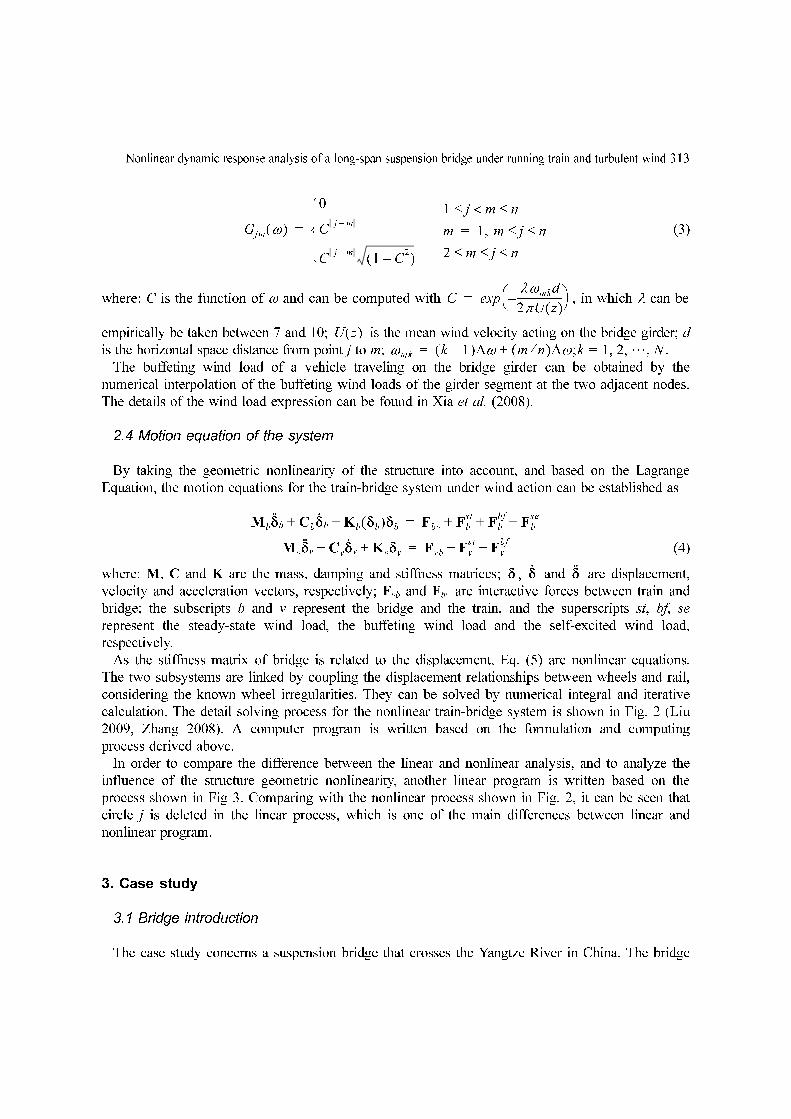
(3)
where: C is the function of ω and can be computed with , in which λ can be
empirically be taken between 7 and 10; is the mean wind velocity acting on the bridge girder; d
is the horizontal space distance from point j to m; .
The buffeting wind load of a vehicle traveling on the bridge girder can be obtained by the
numerical interpolation of the buffeting wind loads of the girder segment at the two adjacent nodes.
The details of the wind load expression can be found in Xia et al. (2008).
2.4 Motion equation of the system
By taking the geometric nonlinearity of the structure into account, and based on the Lagrange
Equation, the motion equations for the train-bridge system under wind action can be established as
(4)
where: M, C and K are the mass, damping and stiffness matrices; , and are displacement,
velocity and acceleration vectors, respectively; Fvb and Fbv are interactive forces between train and
bridge; the subscripts b and v represent the bridge and the train, and the superscripts st, bf, se
represent the steady-state wind load, the buffeting wind load and the self-excited wind load,
respectively.
As the stiffness matrix of bridge is related to the displacement, Eq. (5) are nonlinear equations.
The two subsystems are linked by coupling the displacement relationships between wheels and rail,
considering the known wheel irregularities. They can be solved by numerical integral and iterative
calculation. The detail solving process for the nonlinear train-bridge system is shown in Fig. 2 (Liu
2009, Zhang 2008). A computer program is written based on the formulation and computing
process derived above.
In order to compare the difference between the linear and nonlinear analysis, and to analyze the
influence of the structure geometric nonlinearity, another linear program is written based on the
process shown in Fig 3. Comparing with the nonlinear process shown in Fig. 2, it can be seen that
circle j is deleted in the linear process, which is one of the main differences between linear and
nonlinear program.
3. Case study
3.1 Bridge introduction
The case study concerns a suspension bridge that crosses the Yangtze River in China. The bridge
Gjm ω( )
0
C j m–
C j m–
1 C2
–( )⎩⎪⎨⎪⎧
=
1 j m< n≤ ≤
m 1, m j n≤ ≤=
2 m j n≤ ≤ ≤
Cλωmkd
2πU z( )------------------–⎝ ⎠
⎛ ⎞exp=
U z( )ωmk k 1–( )∆ω m n⁄( )∆ω ;k 1 2 …, ,= N,+=
Mbδ··b Cbδ
·b Kb δb( )δb+ + Fbv Fb
stFb
bfFb
se+ + +=
Mvδ··v Cvδ
·v Kvδv+ + Fvb Fv
stFv
bf+ +=
δ δ·
δ··

314 S.Q. Wang, H. Xia, W.W. Guo and N. Zhang
has a main span of 1120 m and two side spans of 112 m + 84 m, and the height of the tower is 200
m measured from the base level to the tower saddle, as shown in Fig. 4. The height of the truss is
16 m and the panel length is 14 m. The distance between the two main trusses is 30 m. The double
bridge deck is suspended by suspenders in the main span to allow a sufficiently large navigation
channel. Each suspending point has two suspenders. The upper deck is 43 m wide and carries 8
roadway lines, while the lower deck is 30 m wide and carries 4 railway tracks, as shown in Fig. 5.
The spatial finite element model of the whole bridge is shown in Fig. 6. The two reinforced
concrete towers and the members of the truss of the bridge, including the main truss members,
stringers and cross beams, are modeled by three dimensional beam elements. The cables and the
suspenders are modeled by two-dimensional truss elements, and the steel deck by plate elements.
Fig. 2 Process for solving the nonlinear wind-train-bridge system
Fig. 3 Process for solving the linear wind-train-bridge system
Fig. 4 Configuration of the suspension bridge

Nonlinear dynamic response analysis of a long-span suspension bridge under running train and turbulent wind 315
The modal analysis on this bridge is performed by the general structure analysis software MIDAS.
The result shows that the natural frequencies of the bridge are spaced very closely together. Its first
20 natural frequencies include: 1 longitudinal vibration mode, 7 vertical nodes, 6 lateral modes, and
6 coupling modes between lateral vibration and torsional vibrations. Some modes of the bridge can
be found in Fig. 7.
The train concerned in the case study is composed of one electrically-powered locomotive SS8
followed by 18 passenger cars (Guo 2004). The train speed range in calculation is 100-300 km/h.
Fig. 5 Cross-section of bridge girder
Fig. 6 FEM model of the long-span suspension bridge

316 S.Q. Wang, H. Xia, W.W. Guo and N. Zhang
The vertical, lateral and torsional irregularities of the track on the bridge are taken into
consideration as the self-excitations by using the measured data from the Zhengzhou-Wuhan railway
in China (Xia 2000).
3.2 Wind simulation
The spectra for horizontal and vertical burbulent wind veloctiy are defined by
(5)
The wind velocity field on the bridge girder is assumed to be composed of 189 wind velocity
waves at 189 different points uniformly distributed along the bridge, with 40 points before the
bridge, 109 along the bridge and 40 points after it, the intervals is 14 m. The sampling number of
frequency is 256 and the frequency interval is 0.004 Hz. The time interval of the generated wind
velocity is 0.1 s. The simulated velocities with U = 10 m/s at the middle span of the bridge are
shown in Fig. 8.
3.3 Nonlinearity influence
Calculated by the linear and nonlinear programs, the influence of the structure geometric
nonlinearity is analyzed. When the train speed is 100 km/h, and the mean velocity of the turbulent
wind is 10 m/s, the simulated vertical deflection and lateral displacement histories at the middle of
the main span and the 2nd span of bridge girder are shown in Fig. 9 and Fig. 10, respectively.
Su n( )200f z( )u*
2
n 1 50f z( )+[ ]5 3⁄---------------------------------------=
Sw n( )6f z( )u*
2
n 1 4f z( )+[ ]2--------------------------------=
⎩⎪⎪⎨⎪⎪⎧
Fig. 7 Vibration modes of the long-span suspension bridge

Nonlinear dynamic response analysis of a long-span suspension bridge under running train and turbulent wind 317
Fig. 8 Simulated wind velocity curves at mid-span of bridge deck
Fig. 10 Comparison of bridge lateral displacement histories
Fig. 9 Comparison of bridge vertical deflection histories

318 S.Q. Wang, H. Xia, W.W. Guo and N. Zhang
It can be seen from the figures that
(1) The variation tendency of the bridge displacement histories is not obviously influenced by the
geometric nonlinearity of the structure;
(2) Both the vertical and lateral maximum displacements are obviously different while considering
the geometric nonlinearity of the structure. For example, the linear maximum vertical
deflection of the main span is 51.23 cm, while the nonlinear value is 49.80 cm, 2.8 percent
discrepancy is occurred, and the corresponding discrepancy between linear and nonlinear
result of the 2nd span is 7.9 percent. The linear maximum lateral displacement of the main
span is 109 mm, while the corresponding nonlinear value is 103 mm, 5.5 percent discrepancy
is occurred, and the linear and nonlinear analysis discrepancy of the 2nd span is 7.4 percent.
As the result of the above analysis, the geometric nonlinearity of the long-span suspension bridge
should not be neglected in the calculation of wind-train-bridge coupling system.
3.4 Influences of train speed and wind velocity
By taking the geometric nonlinearity of the long-span suspension bridge into account, the
simulated vertical and lateral deflections of the main span with and without wind load are drawn in
Fig. 11 and Fig. 12, respectively, while the corresponding train speed is 200 km/s.
Fig. 11 Comparison of bridge vertical deflections with and without wind action
Fig. 12 Comparison of bridge lateral displacements with and without wind action

Nonlinear dynamic response analysis of a long-span suspension bridge under running train and turbulent wind 319
Shown in Fig. 13 are the three dimensional distribution of vertical deflection and lateral
displacement of bridge mid-span versus train speed and wind velocity, when the train passes the
bridge at the speed of 100-300 km/h, and the mean velocity of the turbulent wind is 0-20 m/s.
From Fig. 11 to Fig. 13, the dynamic characteristics of the long span suspension bridge under
train and wind actions can be observed as follows:
(1) The vertical deflections of bridge are mainly induced by the train gravity load, the influence of
wind velocity is small, and the maximum deflections are a little more sensitive to the train
speed than the wind velocity.
(2) The maximum lateral displacement of bridge is 0.12 cm due to moving train without wind, but
that under the attack of wind is significantly increased to 45.63 cm. Therefore, it can be seen
that the lateral displacements of bridge are mainly controlled by wind loads, which are more
sensitive to the wind than the vertical deflections. For such a long-span suspension bridge, the
influence of train speed on the bridge lateral displacement is much smaller than wind velocity.
4. Conclusions
Considering the wind load acting on the train and bridge coupling system, and taking the
geometric nonlinearity into account, a dynamic model of wind-train-bridge system is established,
and a corresponding computer program is written. The case study demonstrated that the proposed
framework and the associated computer program can efficiently predict the dynamic responses of
long-span suspension bridge system under turbulent wind and running train. The following
conclusions have been drawn from the above analysis:
(1) The geometric nonlinearity does not influence the variation tendency of the bridge in vertical
deflection and lateral displacement histories, but the maximum responses will be changed.
(2) The influence of wind velocity on the maximum responses of the long-span suspension bridge
is obviously, and the lateral displacements are more sensitive to the wind than the vertical ones.
(3) Compared with wind velocity, train speed only has a little influence on the lateral maximum
responses, but it affects the vertical ones a little more clearly.
Fig. 13 Responses of bridge mid-span vs wind velocity and train speed

320 S.Q. Wang, H. Xia, W.W. Guo and N. Zhang
In a word, both nonlinearity and wind have great influences on the dynamic responses of train-
bridge system, to which great attention should be paid.
Acknowledgements
The research of this project is supported by the National Natural Science Foundation of China
(90715008) and the Flander (Belgium)-China Bilateral Project (BIL 07/17).
References
Boonyapinyo, V., Yamada, H. and Miyata, T. (1994), “Wind-induced nonlinear lateral-torsion buckling of cable-stayed bridges”, J. Struct. Eng. -ASCE, 2, 486-506.
Cao, Y.H., Xiang, H.F. and Zhou, Y. (2000), “Simulation of stochastic wind velocity field on long-span bridges”,Eng. Mech., l(126), 1-6.
Chen, X.Z., Kareem, A. and Han, F.L. (2000), “Nonlinear aerodynamic analysis of bridge under turbulent winds:the new frontier in bridge aerodynamics”, Proceedings of the international Conference on Advances instructural Dynamics, Hong Kong, China.
Flýba, L. (1996), Dynamics of railway bridges, Thomas Telford, London, England.Guo, W.H. and Xu, Y.L. (2006), “Safety analysis of moving road vehicles on a long bridge under crosswind”, J.
Eng. Mech. -ASCE, 4, 438-446.Guo, W.W. (2004), “Dynamic responses of long span bridges and running safety of trains under wind action”,
PhD Dissertation, Beijing Jiaotong University.Guo, W.W., Xia, H. and Zhang N. (2004), “Dynamic responses of long suspension bridges and running safety of
trains under wind action”, Progress in Safety Science and Technology, Beijing/New York.Guo, X.R. and Zeng, Q.Y. (2001), “Analysis of critical wind speed for running trains on a schemed Yangtze
River bridge at Nanjing on Jing-Hu high speed railway line”, J. China Railway Soc., 23(5), 75-80. (inChinese)
Larsen, Allan (1998), “Advances in aeroelastic analyses of suspension and cable-stayed bridges”, J. Wind Eng.Ind. Aerod., 74-76, 73-90.
Liu, K., Reynders, E., De Roeck, G. and Lombaert, G. (2009), “Experimental and numerical analysis of acomposite bridge for high-speed trains”, J. Sound Vib., 320, 201-220.
Pan, Y.R. (2004), Non-linear analysis theory method for suspension bridge structures, China CommunicationsPress. (in Chinese)
Xia, H. and Guo, W.W. (2008), “Dynamic analysis of a train-bridge system under wind action”, Comput. Struct.,86, 1845-1855.
Xia, H., Xu, Y.L. and Chan, T.H.T. (2000), “Dynamic interaction of long bridges with running trains”, J. SoundVib., 237(2), 263-280.
Xu, Y.L., Xia, H. and Yan, Q.S. (2003), “Dynamic response of suspension bridge to high wind and runningtrain”, J. Bridge Eng., 8(1), 46-55.
Xu, Y.L., Zhang, N. and Xia, H. (2004), “Vibration of couple train and cable-stayed bridge systems in crosswinds”, Eng. Struct., 26, 1389-1406.
Yang, Y.B. (2008), "Wind-induced aerostatic instability of cable-supported bridges by a two-stage geometricnonlinear analysis”, Interact. Multiscale Mech., 1(3), 381-396.
Zhang, N., Xia, H. and Guo, W.W. (2008), “Vehicle-bridge interaction analysis under high-speed train”, J. SoundVib., 309, 407- 425.
Zhang, N., Xia, H. and Guo, W.W. (2009), “Analysis on the wind-vehicle-bridge coupling vibration for NanjingDashengguan Yangtze River bridge of Beijing-Sanghai high-speed railway”, J. China Railway Sci., 30(1), 41-48. (in Chinese)