
Nonlinear coupled mechanics and initial buckling of composite plates with piezoelectric actuators...
8
Nonlinear coupled mechanics and initial buckling of composite plates with piezoelectric actuators and sensors This article has been downloaded from IOPscience. Please scroll down to see the full text article. 2002 Smart Mater. Struct. 11 330 (http://iopscience.iop.org/0964-1726/11/3/302) Download details: IP Address: 152.11.242.100 The article was downloaded on 14/09/2013 at 14:48 Please note that terms and conditions apply. View the table of contents for this issue, or go to the journal homepage for more Home Search Collections Journals About Contact us My IOPscience
-
Upload
dimitris-a -
Category
Documents
-
view
213 -
download
0
Transcript of Nonlinear coupled mechanics and initial buckling of composite plates with piezoelectric actuators...

Nonlinear coupled mechanics and initial buckling of composite plates with piezoelectric
actuators and sensors
This article has been downloaded from IOPscience. Please scroll down to see the full text article.
2002 Smart Mater. Struct. 11 330
(http://iopscience.iop.org/0964-1726/11/3/302)
Download details:
IP Address: 152.11.242.100
The article was downloaded on 14/09/2013 at 14:48
Please note that terms and conditions apply.
View the table of contents for this issue, or go to the journal homepage for more
Home Search Collections Journals About Contact us My IOPscience
INSTITUTE OF PHYSICS PUBLISHING SMART MATERIALS AND STRUCTURES
Smart Mater. Struct. 11 (2002) 330–336 PII: S0964-1726(02)35716-1
Nonlinear coupled mechanics and initialbuckling of composite plates withpiezoelectric actuators and sensorsDimitris Varelis and Dimitris A Saravanos1
Department of Mechanical Engineering and Aeronautics, University of Patras,Patras GR26500, Greece
E-mail: [email protected]
Received 6 August 2001, in final form 13 March 2002Published 16 May 2002Online at stacks.iop.org/SMS/11/330
AbstractThe nonlinear mechanics for piezoelectric laminates and plates is presented,including nonlinear effects due to large displacements and rotations. Themechanics is incorporated into the piezoelectric mixed-field laminate theory.Using this mechanics, a nonlinear finite-element method and an incrementalsolution are formulated for the nonlinear analysis of adaptive platestructures. An eight-node-plate finite element is developed. The mechanicsis applied to predict the buckling of piezoelectric plates induced bycombined electromechanical loading. Application cases quantify themechanical buckling of composite beams and plates with piezoelectricsensors, the piezoelectric buckling of active beams and plates, and thefeasibility of active buckling compensation.
1. Introduction
During recent years the study of composite materials andanalysis of smart/adaptive structures has received substantialattention. A significant part of this effort has been directedtowards the development of piezoelectric composite structures,that is, composite structures with embedded piezoelectricactuators and sensors. Among the many issues whichhave surfaced so far, one is that the severity and type ofelectromechanical loading may exceed the linear range, thusinducing nonlinear behavior and new modes of failure suchas buckling or structural stability problems. This mandatesthe development of nonlinear mechanics for the accurateprediction of the nonlinear response of adaptive piezoelectriccomposite structures. The present paper addresses this voidin technology, by presenting nonlinear mechanics and a finiteelement for the buckling analysis of piezoelectric compositelaminated plate structures.
A vast number of analytical and computational models forsmart/adaptive piezoelectric structures using various theorieshave been reported (see for example the recent reviews bySunar and Rao [1] and Saravanos and Heyliger [2]). Yet, mostof the analytical and computational models reported so far have
1 Author to whom any correspondence should be addressed.
been limited to the linear region and have been mainly focusedon the static and dynamic response of smart structures.
Limited work has been reported on the nonlinear responseof piezoelectric structures. In the area of piezoelectric materialnonlinearity, Fripp and Hagood [3] developed a framework forthe dynamic behavior of a nonlinear electrostrictive system.A finite-element model which describes the static analysis ofelectrostrictive materials was proposed by Dubus et al [4].Lee and Saravanos [5] developed the mechanics and a finiteelement for thermal piezocomposite plates with temperature-dependent material properties. A fully nonlinear theory forthe dynamics and active control of piezoelectric laminatedplates was studied by Pai et al [6]. An analytical model wasformulated by Tzou and Bao [7] and, on the basis of this, theactive control of nonlinear deflection and thermal buckling ofpiezothermoelastic circular plates were studied by Tzou andZhou [8]. Finally, Zhou and Tzou [9] investigated the case ofthe active control of a piezoelectric laminated circular sphericalshallow shell for static and dynamic behavior.
The present paper presents coupled nonlinear mechanicsfor the analysis of piezocomposite laminates and plates,considering nonlinear effects due to large rotations. Thegoverning nonlinear material equations are presented.The material equations are subsequently combined with
0964-1726/02/030330+07$30.00 © 2002 IOP Publishing Ltd Printed in the UK 330

Nonlinear coupled mechanics and initial buckling of composite plates with piezoelectric actuators and sensors
Figure 1. Assumed through-the-thickness displacement and electric potential fields.
the kinematic assumptions of the so-called mixed-fieldpiezoelectric laminate theory [10] to yield a coupled nonlinearpiezoelectric laminate theory which uses both displacementsand electric potential as field variables. An incrementalfinite-element formulation is further described and a parabolicnonlinear piezocomposite plate element is developed. Theproblem of buckling of piezocomposite plates subject tocombined mechanical and electric loads is subsequentlyaddressed and solved. Various evaluations and applications ofthe method are shown for the cases of mechanical buckling ofsensory beams and plates, and piezoelectric buckling of activeplates. Finally the case of active buckling compensation isinvestigated.
Governing equations
The material of each ply of the piezoelectric laminate isassumed to remain within the range of linear piezoelectricity,with constitutive equations of the form
σi = CEij Sj − eikEk Dl = elj Sj + εS
lkEk (1)
where i, j = 1, . . . , 6 and k, l = 1, . . . , 3; σi and Sj arethe mechanical stresses and engineering strains in extendedvectorial notation, Cij is the elastic stiffness tensor, eik isthe piezoelectric tensor, Ek is the electric field vector, Dl
is the electric displacement vector, and εlk is the electricpermittivity tensor. The previous equations describe thematerial behavior either on the orthogonal material axes 1,2, 3 or the structural axes x, y and z, respectively, providedthat proper transformations are applied to material propertymatrices.
The Green strains in each ply are assumed to have thefollowing form:
S1 = u,x + 12w2
,x S2 = v,y + 12w2
,y
S6 = (u,y + v,x) + w,xw,y S4 = βx + w,x
S5 = βy + w,y S3 = 0
(2)
where the first RHS terms describe the linear straincomponents, while the last RHS terms are the nonlinear straincomponents due to large rotations.
Kinematic assumptions
The mixed-field laminate theory [10] is used; it combines alinear displacement field with a layerwise electric potential
field, to capture all state variables through the thickness. Thelayerwise field divides the laminate into N − 1 sublaminatesand assumes a continuous electric potential field through thesublaminate, such that a piecewise-continuous field resultsthrough the whole thickness of the piezolaminate, as seen infigure 1. The assumed displacements and electric potentialhave the following form through the thickness:
u(x, y, z, t) = u0(x, y, t) + zβx(x, y, t)
v(x, y, z, t) = v0(x, y, t) + zβy(x, y, t)
w(x, y, z, t) = w0(x, y, t)
φ(x, y, z, t) =N∑
m=1
φm(x, y, t)�m(z)
(3)
where u0, v0, w0 are mid-surface displacements, βx andβy are rotation angles, φm are electric potential valuesdescribing the layerwise electric potential field, �m arelinear interpolation functions. In the context of the previouskinematic assumptions (equation (3)) and nonlinear strainrelations (equation (2)), the strains through the thickness ofthe laminate take the following form:
S1
S2
S6
=
S01
S02
S06
+ z
k01
k02
k06
+
SL1
SL2
SL6
(4)
where the S0i are in-plane and out-of-plane shear mid-surface
strains:
S01 = u0
,x, S02 = v0
,y, S06 = u0
,y + v0,x
S03 = 0, S0
4 = βx + w0,x, S0
5 = βy + w0,y .
(5)
k0i are the mid-surface curvatures,
k01 = βx,x, k0
2 = βy,y, k06 = βx,y + βy,x (6)
and SLi are the nonlinear laminate strains and are expressedbelow:
SL1 = 12w02
,x SL2 = 12w02
,y SL6 = w0,xw
0,y . (7)
The electric field vector takes the form
Ei(x, y, ζ, t) =N∑
m=1
Emi (x, y, t)�m(ζ ) i = 1, 2
E3(x, y, ζ, t) =N∑
m=1
Em3 (x, y, t)�m
,ζ (ζ )
(8)
331

D Varelis and D A Saravanos
(a)
P
(b)
z, w
PZT-5
PZT-5
0 ply
90 ply x, u
∆φA
∆φA
Figure 2. Piezoelectric composite structures. (a) Cantilever beam;(b) plate.
where the generalized electric field vector Em is defined as
Em1 = −�m
,x Em2 = −�m
,y Em3 = −�m. (9)
Generalized equations of motion
The mechanical and electrical response of the piezoelectricmaterial can be represented by the stress equilibrium and theconservation-of-electric-charge equations respectively:
ρui = σij,j + fi i, j = 1, . . . , 3
Di,i = 0 i = 1, . . . , 3.(10)
Through the use of the divergence theorem, equilibriumequations can be expressed over the volume of the piezoelectriclaminate in an equivalent variational form as
{δu}{�u} = −∫
V
δSi σi dV +∫
V
δuj ρuj dV
+∫
τ
δuj τj d = 0
{δϕ}{�e} = −∫
V
δEj Dj dV +∫
q
δϕ q d = 0
i = 1, . . . , 6; j = 1, . . . , 3
(11)
where �u, �e are differences between internal and externalnodal forces and charges, τi are the surface tractions onthe bounding surface τ , q is the electrical charge appliedon the surface q , and V represents the whole laminatevolume including both composite and piezoelectric layers. Theincrement step of equation (11) in generalized form can beexpressed in the following way:
{δu}{d�u} =∫
A0
({δS0}[A]{dS0} + {δS0}[B]{dk0}
+ {δk0}[B]{dS0} + {δk0}[D]{dk0}+ {δ(dSL)}{N} + {δSL}[A]{dS0}+ {δSL}[B]{dk0} + {δS0}[A]{dSL}+ {δk0}[B]{dSL} + {δSL}[A]{dSL} + {δS0}[E]{dEm}+ {δk0}[E]{dEm} + {δSL}[E]{dEm}) dA
{δφ}{d�e} =∫
A0
({δEm}[E]{dS0} + {δEm}[E]{dk0}
+ {δEm}[E]{dSL} + {δEm}[G]{dEm}) dA
(12)
where A, B, D are equivalent stiffness matrices, E, E arelaminate piezoelectric matrices, and G are electric permittivitymatrices of the laminate [10].
2. Finite-element formulation
A finite-element formulation for a composite piezoelectricplate is obtained, encompassing the previous generalizednonlinear laminate formulation. The state variables areapproximated on the reference mid-plane A0 with planeinterpolation functions of the following form:
u0j (x, y, t) =
M∑i=1
u0ij (t)Ni(x, y), j = 1, . . . , 3
β0j (x, y, t) =
M∑i=1
βij (t)N
i(x, y), j = 1, . . . , 2
φmj (x, y, t) =
M∑i=1
φmi(t)Ni(x, y), m = 1, . . . , N
(13)where M is the number of in-plane nodes, and N indicatesthe number of unknown electric potential values describingthe layerwise representation through the laminate thickness.A parabolic eight-node element of the serendipity family withfive structural and N electric degrees of freedom per node isconsidered. Substituting equations (1)–(9) into (12) togetherwith (13), and collecting the common terms, the incrementalequations of motion for a geometrically nonlinear piezoelectricplate structure are obtained in the form of a coupled system:
([K0uu] + [Kσ
uu] + [KLuu]){du} + ([K0
ue] + [KLue]){dφ}
= −[Muu]{du} + {�u} (14)
([K0eu] + [KL
eu]){du} + [K0ee]{dφ} = {�e}
where: all sums of matrices [K] in parentheses aretangential structural and piezoelectric matrices indicated byoverbars; subscripts uu, ue, ee indicate elastic, piezoelectric,and permittivity matrices respectively; superscripts 0, σ ,L respectively indicate linear, initial stress, and nonlineartangential matrix components; du and dφ are unknownincrements of displacements and electric potential; {�u} arethe imbalances between internal and external nodal forces,and {�e} are imbalances between internal and external nodalcharges at each step (equation (11)).
332
Nonlinear coupled mechanics and initial buckling of composite plates with piezoelectric actuators and sensors
Table 1. Mechanical properties (ε0 = 8.85 × 10⁻¹² F m−1, electric permittivity of air).
Composite T300/934 PZT-5
Elastic properties:E11 (GPa) 132.4 62E22 (GPa) 10.8 62G23 (GPa) 3.6 18G13 (GPa) 5.6 23.6G12 (GPa) 5.6 23.6ν12 0.24 0.31ν13 0.24 0.31ν23 0.49 0.31
Piezoelectric coefficients (10−12 m V−1):d31 0 −220d32 0 −220d24 0 670d15 0 670
Electric permittivity:ε11/ε0 3.5 2598ε22/ε0 3 2598ε33/ε0 3 2598Mass density 1578 7400
Three new matrices are introduced by the nonlinear strainsinto the equations of motion, the initial stress matrix Kσ
uu, thenonlinear stiffness matrix KL
uu, and the nonlinear piezoelectricmatrix KL
ue. The terms of the initial stress matrix are furtheranalysed and are found to have the following form between thenodes i, j of the element:
[Kijσ ] =
∫A
[Ri]T
[N1 N6
N6 N2
][Rj ] dA (15)
where R is the matrix of strain shape functions. Ni are the in-plane initial laminate forces which include the effect of bothexternal mechanical loads and applied electrical voltages, asdescribed by the generalized laminate constitutive equation,shown below:
Ni =∫ h
0σi dz = AijS
0j + Bij k
0j −
N∑m=1
Em3iE
m3
i, j = 1, 2, 6
(16)
In the previous equation, the first two RHS terms are theaverage mechanical stress components due to extension andextension–flexure coupling, while the third term represents theaverage piezoelectric stress due to applied electric field.
Initial buckling
Neglecting the nonlinear stiffness matrices (indicated bysuperscript L), equation (14) yields the initial bucklingequations at the point of equilibrium ({�u} = {�e} = 0):
([K0uu] − λ[Kσ
uu]){du} + [K0ue]{dφ} = 0
[K0eu]{du} + [K0
ee]{dφ} = 0(17)
where λ is the critical factor for the applied mechanical load orapplied electrical voltage on piezoelectric actuators that willrender the plate unstable. The solution of the buckling problemis based on two incremental steps. In the first step, a knownmechanical, electrical, or combined electromechanical load isapplied to the structure and, using initial stiffness matrices, the
average laminate stresses are calculated and the correspondingstress matrix Kσ
uu is subsequently formulated. In the secondstep, the eigenvalue problem (17) is solved and critical bucklingloads and shapes are calculated.
3. Numerical results
In this section, evaluations of the models developed arepresented for piezoelectric beams and plates. Comparisonsof calculated results with those from analytical solutions formechanical buckling are shown. The materials considered aregraphite/epoxy (Gr/Ep) composite and PZT5 piezoceramic,whose properties are shown in table 1. Unless otherwise stated,the thickness of each composite ply was 0.125 mm and thatof each piezoelectric layer was 0.25 mm. The location ofthe piezoelectric layers is indicated by the letter p in standardlaminate notation.
[p/0/90/45/−45]s sensory beam
The mechanical buckling of a clamped–free [p/0/90/45/−45]scomposite beam with Gr/Ep plies and with two continuousPZT5 layers attached on the upper and lower surfaces isexamined. The width of the beam was Lη = 10 mm, the lengthwas Lξ = 200 mm, and the thickness was h = 1.5 mm. Auniform axial (x-direction) compressive line force is applied atthe free end. Two different electric conditions were considered.In the first case, closed-circuit (CC) electric conditions wereconsidered at each piezoelectric layer, i.e. 0 V were applied onthe top and bottom electrodes of each piezoelectric layer. Inthe second case, the inner terminals were grounded while theouter terminal of each sensor remained free; this resemblesthe open-circuit (OC) condition typical for a piezoelectricsensor. Table 2 provides the first four critical mechanical loadscalculated using the present model for closed- and open-circuitconditions, as well as an elastic analytical solution [11]. Thereis very good agreement between the present model predictionsfor CC conditions and the elastic analytical solution, whichlends credence to the method. Interestingly, the critical
333

D Varelis and D A Saravanos
0.0
0.2
0.4
0.6
0.8
1.0
1.2
0.00 0.05 0.10 0.15 0.20 0.25
x axial (m)
w/w
max
Figure 3. The transverse normalized displacement w. The firstbuckling mode of a [p/0/90/45/−45]s beam.
0.0E+00
2.0E+03
4.0E+03
6.0E+03
8.0E+03
1.0E+04
1.2E+04
1.4E+04
0.00 0.05 0.10 0.15 0.20 0.25
x axial (m)
Ele
ctri
c P
ote
nti
al (
V/m
)
Figure 4. The electric potential along the x-axis on a free surface ofa piezolayer. The first buckling mode of a [p/0/90/45/−45]s beam.
mechanical loads predicted for OC conditions are higher,and this reflects the fact that electric energy was stored inthe piezolayers, thus reducing both the elastic strain energyand the amount of initial stress in the beam. The resultantdifferent predictions of buckling loads under various electricconditions are the direct result of the mixed-field laminatetheory and the coupled formulation, and illustrate the quality ofthe mechanics. The corresponding first buckling mode of thedisplacement w and the sensory electric potential φ are shownin figures 3 and 4. Figure 5 shows buckling load predictionsfor various thickness aspect ratios. The predicted bucklingloads have been normalized by the analytical elastic beamsolution [11] to illustrate the improved buckling predictionsof the present theory at high thickness compared to classicalbeam theory.
[p/0/90]s plate
A [p/0/90]s Gr/Ep plate was considered with continuous PZT5layers attached on the top and bottom surfaces. The dimensionsof the plate were: Lξ = 200 mm long, Lη = 200 mm wide,and h = 1 mm thick.
Mechanical buckling. A uniform compressive in-plane forceNx was applied on the plate with simple supports. Thepredicted critical mechanical loads with closed- and open-circuit conditions at the terminals of each PZT5 layer, together
0
0.2
0.4
0.6
0.8
1
1.2
1.4
0 50 100 150 200 250L/h
No
rmal
ized
Bu
cklin
g M
ech
anic
al L
oad
open circuitclosed circuit
Figure 5. The effect of the thickness aspect ratio on the firstnormalized mechanical buckling load of a [p/0/90/45/−45]s beamwith open and closed conditions on piezoelectric layers.
Table 2. Critical mechanical buckling loads for a[PZT5/0/90/45/−45]s cantilever beam under a uniform compressiveline force.
Critical load (N m−1)10 × 1 mesh
Elastic analyticalOrder CC OC solution [11]
1 12 13.4 11.82 108 121.2 106.23 295 336 2954 588 661 578
Table 3. Critical mechanical buckling loads for a piezoelectriccomposite plate [PZT5/0/90]s under a uniform in-plane force Nx .
Critical load (kN m−1)8 × 8 mesh
Elastic analyticalOrder CC OC solution [12]
1 5.33 7.22 5.372 8.98 11.94 93 16.5 21.8 16.54 26.7 35.6 27.2
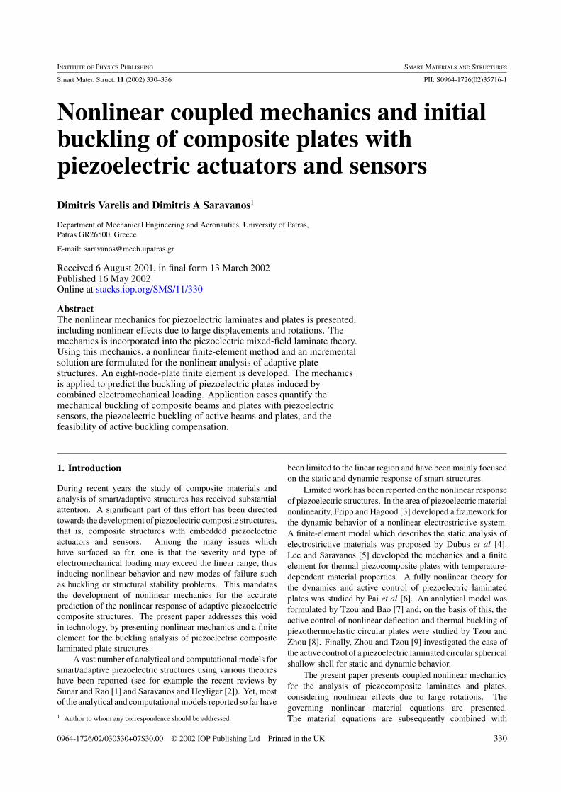
with those derived by a purely elastic analytical solution basedon classical laminate plate theory (CLPT) assumptions [12],are shown in table 3. Again, there is excellent agreementbetween the predictions from the present method for CCconditions and the analytical solution. The predicted criticalloads with OC conditions are higher, for the reasons previouslyexplained, and indicate the value of the coupled formulation.The predicted displacement w and sensory electric potential φ
of the first buckling mode are shown in figures 6 and 7.
Piezoelectric buckling. It is conceivable that under a highelectric potential applied to the piezoelectric actuators, in-plane stress may develop in the plate which may reachvalues that will cause loss of stiffness and buckling. Thisrepresents a new mode of instability and failure unique tosmart piezoelectric structures, termed, hereafter, piezoelectricbuckling. The present example considers such cases ofpiezoelectric buckling when the inner terminals of thepiezoelectric layers are grounded (0 V) and a uniform in-planeelectric potential pattern of φA and −φA is applied on the
334
Nonlinear coupled mechanics and initial buckling of composite plates with piezoelectric actuators and sensors
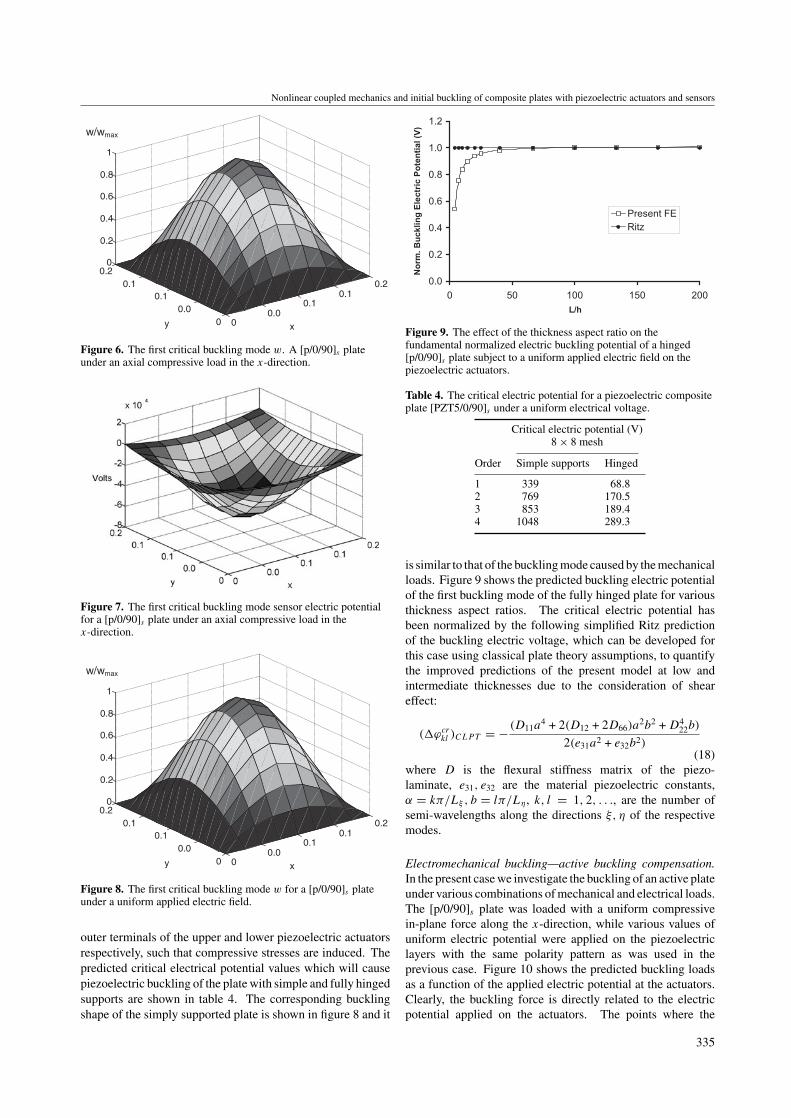
00.0
0.10.1
0.2
00.0
0.1 0.1
0.2 0
0.2
0.4
0.6
0.8
1
xy
w/wmax
Figure 6. The first critical buckling mode w. A [p/0/90]s plateunder an axial compressive load in the x-direction.
Figure 7. The first critical buckling mode sensor electric potentialfor a [p/0/90]s plate under an axial compressive load in thex-direction.
00.0
0.10.1
0.2
00.0
0.1 0.1
0.2 0
0.2
0.4
0.6
0.8
1
xy
w/wmax
Figure 8. The first critical buckling mode w for a [p/0/90]s plateunder a uniform applied electric field.
outer terminals of the upper and lower piezoelectric actuatorsrespectively, such that compressive stresses are induced. Thepredicted critical electrical potential values which will causepiezoelectric buckling of the plate with simple and fully hingedsupports are shown in table 4. The corresponding bucklingshape of the simply supported plate is shown in figure 8 and it
0.0
0.2
0.4
0.6
0.8
1.0
1.2
0 50 100 150 200
L/h
No
rm.
Bu
ck
lin
g E
lec
tric
Po
ten
tia
l (V
)
Present FE
Ritz
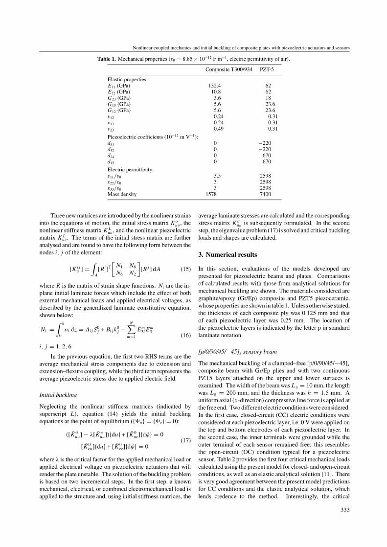
Figure 9. The effect of the thickness aspect ratio on thefundamental normalized electric buckling potential of a hinged[p/0/90]s plate subject to a uniform applied electric field on thepiezoelectric actuators.
Table 4. The critical electric potential for a piezoelectric compositeplate [PZT5/0/90]s under a uniform electrical voltage.
Critical electric potential (V)8 × 8 mesh
Order Simple supports Hinged
1 339 68.82 769 170.53 853 189.44 1048 289.3
is similar to that of the buckling mode caused by the mechanicalloads. Figure 9 shows the predicted buckling electric potentialof the first buckling mode of the fully hinged plate for variousthickness aspect ratios. The critical electric potential hasbeen normalized by the following simplified Ritz predictionof the buckling electric voltage, which can be developed forthis case using classical plate theory assumptions, to quantifythe improved predictions of the present model at low andintermediate thicknesses due to the consideration of sheareffect:
(�ϕcrkl )CLPT = − (D11a
4 + 2(D12 + 2D66)a2b2 + D4
22b)
2(e31a2 + e32b2)(18)
where D is the flexural stiffness matrix of the piezo-laminate, e31, e32 are the material piezoelectric constants,α = kπ/Lξ , b = lπ/Lη, k, l = 1, 2, . . ., are the number ofsemi-wavelengths along the directions ξ, η of the respectivemodes.
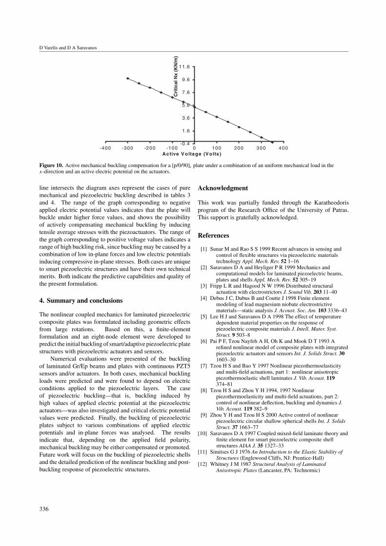
Electromechanical buckling—active buckling compensation.In the present case we investigate the buckling of an active plateunder various combinations of mechanical and electrical loads.The [p/0/90]s plate was loaded with a uniform compressivein-plane force along the x-direction, while various values ofuniform electric potential were applied on the piezoelectriclayers with the same polarity pattern as was used in theprevious case. Figure 10 shows the predicted buckling loadsas a function of the applied electric potential at the actuators.Clearly, the buckling force is directly related to the electricpotential applied on the actuators. The points where the
335
D Varelis and D A Saravanos
-0 .4
1.6
3.6
5.6
7.6
9.6
11.6
-400 -300 -200 -100 0 100 200 300 400Active Voltage (Vo lts )
Cri
tica
l Nx
(KN
/m)
Figure 10. Active mechanical buckling compensation for a [p/0/90]s plate under a combination of an uniform mechanical load in thex-direction and an active electric potential on the actuators.
line intersects the diagram axes represent the cases of puremechanical and piezoelectric buckling described in tables 3and 4. The range of the graph corresponding to negativeapplied electric potential values indicates that the plate willbuckle under higher force values, and shows the possibilityof actively compensating mechanical buckling by inducingtensile average stresses with the piezoactuators. The range ofthe graph corresponding to positive voltage values indicates arange of high buckling risk, since buckling may be caused by acombination of low in-plane forces and low electric potentialsinducing compressive in-plane stresses. Both cases are uniqueto smart piezoelectric structures and have their own technicalmerits. Both indicate the predictive capabilities and quality ofthe present formulation.
4. Summary and conclusions
The nonlinear coupled mechanics for laminated piezoelectriccomposite plates was formulated including geometric effectsfrom large rotations. Based on this, a finite-elementformulation and an eight-node element were developed topredict the initial buckling of smart/adaptive piezoelectric platestructures with piezoelectric actuators and sensors.
Numerical evaluations were presented of the bucklingof laminated Gr/Ep beams and plates with continuous PZT5sensors and/or actuators. In both cases, mechanical bucklingloads were predicted and were found to depend on electricconditions applied to the piezoelectric layers. The caseof piezoelectric buckling—that is, buckling induced byhigh values of applied electric potential at the piezoelectricactuators—was also investigated and critical electric potentialvalues were predicted. Finally, the buckling of piezoelectricplates subject to various combinations of applied electricpotentials and in-plane forces was analysed. The resultsindicate that, depending on the applied field polarity,mechanical buckling may be either compensated or promoted.Future work will focus on the buckling of piezoelectric shellsand the detailed prediction of the nonlinear buckling and post-buckling response of piezoelectric structures.
Acknowledgment
This work was partially funded through the Karatheodorisprogram of the Research Office of the University of Patras.This support is gratefully acknowledged.
References
[1] Sunar M and Rao S S 1999 Recent advances in sensing andcontrol of flexible structures via piezoelectric materialstechnology Appl. Mech. Rev. 52 1–16
[2] Saravanos D A and Heyliger P R 1999 Mechanics andcomputational models for laminated piezoelectric beams,plates and shells Appl. Mech. Rev. 52 305–19
[3] Fripp L R and Hagood N W 1996 Distributed structuralactuation with electrostrictors J. Sound Vib. 203 11–40
[4] Debus J C, Dubus B and Coutte J 1998 Finite elementmodeling of lead magnesium niobate electrostrictivematerials—static analysis J. Acoust. Soc. Am. 103 3336–43
[5] Lee H J and Saravanos D A 1998 The effect of temperaturedependent material properties on the response ofpiezoelectric composite materials J. Intell. Mater. Syst.Struct. 9 503–8
[6] Pai P F, Tzou Nayfeh A H, Oh K and Mook D T 1993 Arefined nonlinear model of composite plates with integratedpiezoelectric actuators and sensors Int. J. Solids Struct. 301603–30
[7] Tzou H S and Bao Y 1997 Nonlinear piezothermoelasticityand multi-field actuations, part 1: nonlinear anisotropicpiezothermoelastic shell laminates J. Vib. Acoust. 119374–81
[8] Tzou H S and Zhou Y H 1994, 1997 Nonlinearpiezothermoelasticity and multi-field actuations, part 2:control of nonlinear deflection, buckling and dynamics J.Vib. Acoust. 119 382–9
[9] Zhou Y H and Tzou H S 2000 Active control of nonlinearpiezoelectric circular shallow spherical shells Int. J. SolidsStruct. 37 1663–77
[10] Saravanos D A 1997 Coupled mixed-field laminate theory andfinite element for smart piezoelectric composite shellstructures AIAA J. 35 1327–33
[11] Simitses G J 1976 An Introduction to the Elastic Stability ofStructures (Englewood Cliffs, NJ: Prentice-Hall)
[12] Whitney J M 1987 Structural Analysis of LaminatedAnisotropic Plates (Lancaster, PA: Technomic)
336


