Nonlinear Control Analysis of a Double-Gimbal Variable - AIAA
7
Nonlinear Control Analysis of a Double-Gimbal Variable-Speed Control Moment Gyroscope Daan Stevenson ∗ and Hanspeter Schaub † University of Colorado, Boulder, Colorado 80309-0431 DOI: 10.2514/1.56104 A single double-gimbal variable-speed control moment gyroscope is considered as a method for three-dimensional spacecraft attitude control. First, the system’s equations of motion are developed, where gimbal and wheel accelerations are prescribed as control inputs. The resulting necessary motor torques as well as system energy rates are computed for verification. Next, a novel control algorithm is developed from the stability constraint for reference trajectory tracking. In contrast with the control development for single-gimbal variable-speed gyros, a Newton–Raphson scheme is required to solve for the desired double-gimbal variable-speed control moment gyroscope control variables because they appear in cross product and quadratic form, preventing analytical solutions. Analysis of the control theory suggests that the same torque amplification effects exist as in a single-gimbal control moment gyro, but control by a single double-gimbal variable-speed control moment gyroscope device is not robust due to potential configurations that result in control singularities. When these singularities are avoided, a simulation with successful reference trajectory tracking is achieved. Allowing double-gimbal gyros to have variable wheel speeds provides additional torquing capabilities, which is significant if failure modes are considered. As will be shown, a single double-gimbal variable-speed control moment gyroscope device can provide limited three- dimensional attitude control. I. Introduction M OMENTUM exchange devices have long been the preferred solution for long-term attitude control of spacecraft. The benefits over thrusters are that they do not expend nonrenewable fuel reserves nor expel caustic exhaust materials. Rather, momentum exchange devices require only electrical energy that is readily renewable with solar panels. A reaction wheel, the simplest momen- tum exchange device, can exert a torque on the spacecraft in a single orientation when its wheel speed is varied by the motor [1,2]. A single-gimbal control moment gyroscope (CMG) provides addi- tional control by gimbaling a wheel spinning at a constant speed. This produces larger effective torques on the spacecraft but necessitates more complex control laws. While a CMG can easily encounter control singularities, a variable-speed CMG (VSCMG) introduces an extra degree of freedom that can be used to avoid these singularities, although it is similarly engineered [3–6]. The torque amplification mentioned above can be deduced mathematically by considering the equations of motion (EOM) of a VSCMG, as developed by Schaub et al. [7], Schaub and Junkins [8], and McMahon and Schaub [9]. The dominant angular momentum term is a cross-coupled term between the gimbal angle rate _ and the reaction wheel rotation rate . When is large, i.e., the reaction wheel is spun up, and _ is larger than the body angular rates !, this term dominates the torquelike quantities in the EOM and significantly affects the spacecraft angular acceleration with a rela- tively small _ . Since the expressions for the required motor torques do not contain this cross-coupled term, this mode of operation provides large torques on the spacecraft motion without exerting large amounts of energy. In the 1960s and 1970s, there was a research thrust to develop control laws for one or more double-gimbal CMGs with fixed wheel speed, which allows the flywheel to gimbal about two independent axes [10–13]. Such devices were used for attitude control on the Skylab space station and its Apollo Telescope Mount, and they have more recently been implemented on the International Space Station [14]. In contrast with single-gimbal CMGs, each device is capable of producing two torque vectors. However, this increased actuation capability comes at a price. The resulting large set of control torques of a cluster of double-gimbal devices can oppose each other, resulting in higher energy usage in contrast with single-gimbal devices. The benefit of such devices includes reduced issues with CMG singularities, as well as better capabilities to absorb external disturbance torques. The latter feature allows double-gimbal systems to operate longer before a momentum dumping maneuver is required. A drawback of both the variable-speed and double-gimbal CMGs is that they exhibit only two degrees of freedom, and a single such mechanism can therefore never provide full three-dimensional (3-D) attitude control. Moreover, the double-gimbal CMG control laws that are available in the literature [11,12] were developed neglecting inertia contributions from frame structures and motors, and they implemented momentum vector tracking with feedback servocontrol rather than complete nonlinear attitude control. This paper proposes control of a spacecraft using a double-gimbal VSCMG (DGV) with a nonlinear attitude control strategy that accounts for the gimbal frame inertias. Since it contains three torque- producing motors, a single DGV allows for full control of the 3-D spacecraft attitude. The caveat is whether or not singularity config- urations could occur as in the VSCMG. Furthermore, it is desired to determine mathematically whether the same torque amplification effects occur in a DGV. To answer these questions, the EOM and a control stability constraint of the device are developed. Then, a DGV feedback control method is created that avoids any local gimbal rate linearizations. Finally, the dynamics of a spacecraft with a single DGV system is simulated with a control law that uses both the gimbal torques and the reaction wheel mode of the device. The single DGV configuration is employed to illustrate the three-axis control capa- bilities and study the basic DGV control issues. Eventually, multi- DGV configurations would provide enhanced robustness to singular DGV configurations, as well as reduce the flywheel motor torque requirements. However, this paper illustrates that a single Presented at the AAS/AIAA Astrodynamics Specialist Conference, Girdwood, AK, 31 July–4 August 2011; received 24 August 2011; revision received 6 December 2011; accepted for publication 9 December 2011. Copyright © 2011 by Daan Stevenson and Hanspeter Schaub. Published by the American Institute of Aeronautics and Astronautics, Inc., with permission. Copies of this paper may be made for personal or internal use, on condition that the copier pay the $10.00 per-copy fee to the Copyright Clearance Center, Inc., 222 Rosewood Drive, Danvers, MA 01923; include the code 0731-5090/12 and $10.00 in correspondence with the CCC. ∗ Graduate Research Assistant, Department of Aerospace Engineering Sciences. Member AIAA. † Associate Professor, Department of Aerospace Engineering Sciences. Associate Fellow AIAA. JOURNAL OF GUIDANCE,CONTROL, AND DYNAMICS Vol. 35, No. 3, May–June 2012 787
Transcript of Nonlinear Control Analysis of a Double-Gimbal Variable - AIAA

Nonlinear Control Analysis of a Double-Gimbal Variable-SpeedControl Moment Gyroscope
Daan Stevenson∗ and Hanspeter Schaub†
University of Colorado, Boulder, Colorado 80309-0431
DOI: 10.2514/1.56104
A single double-gimbal variable-speed controlmoment gyroscope is considered as amethod for three-dimensional
spacecraft attitude control. First, the system’s equations of motion are developed, where gimbal and wheel
accelerations are prescribed as control inputs. The resulting necessary motor torques as well as system energy
rates are computed for verification. Next, a novel control algorithm is developed from the stability constraint for
reference trajectory tracking. In contrast with the control development for single-gimbal variable-speed gyros, a
Newton–Raphson scheme is required to solve for the desired double-gimbal variable-speed control moment
gyroscope control variables because they appear in cross product and quadratic form, preventing analytical
solutions. Analysis of the control theory suggests that the same torque amplification effects exist as in a single-gimbal
control moment gyro, but control by a single double-gimbal variable-speed control moment gyroscope device is not
robust due to potential configurations that result in control singularities. When these singularities are avoided, a
simulation with successful reference trajectory tracking is achieved. Allowing double-gimbal gyros to have variable
wheel speeds provides additional torquing capabilities, which is significant if failure modes are considered. As will
be shown, a single double-gimbal variable-speed control moment gyroscope device can provide limited three-
dimensional attitude control.
I. Introduction
M OMENTUM exchange devices have long been the preferredsolution for long-term attitude control of spacecraft. The
benefits over thrusters are that they do not expend nonrenewable fuelreserves nor expel caustic exhaust materials. Rather, momentumexchange devices require only electrical energy that is readilyrenewable with solar panels. A reaction wheel, the simplest momen-tum exchange device, can exert a torque on the spacecraft in a singleorientation when its wheel speed is varied by the motor [1,2]. Asingle-gimbal control moment gyroscope (CMG) provides addi-tional control by gimbaling a wheel spinning at a constantspeed. This produces larger effective torques on the spacecraft butnecessitates more complex control laws. While a CMG can easilyencounter control singularities, a variable-speed CMG (VSCMG)introduces an extra degree of freedom that can be used to avoid thesesingularities, although it is similarly engineered [3–6].
The torque amplification mentioned above can be deducedmathematically by considering the equations of motion (EOM) of aVSCMG, as developed by Schaub et al. [7], Schaub and Junkins [8],and McMahon and Schaub [9]. The dominant angular momentumterm is a cross-coupled term between the gimbal angle rate _� and thereaction wheel rotation rate �. When � is large, i.e., the reactionwheel is spun up, and _� is larger than the body angular rates !,this term dominates the torquelike quantities in the EOM andsignificantly affects the spacecraft angular acceleration with a rela-tively small _�. Since the expressions for the required motor torquesdo not contain this cross-coupled term, this mode of operationprovides large torques on the spacecraft motion without exertinglarge amounts of energy.
In the 1960s and 1970s, there was a research thrust to developcontrol laws for one or more double-gimbal CMGs with fixed wheelspeed, which allows the flywheel to gimbal about two independentaxes [10–13]. Such devices were used for attitude control on theSkylab space station and its Apollo Telescope Mount, and they havemore recently been implemented on the International Space Station[14]. In contrast with single-gimbal CMGs, each device is capable ofproducing two torque vectors. However, this increased actuationcapability comes at a price. The resulting large set of controltorques of a cluster of double-gimbal devices can oppose each other,resulting in higher energy usage in contrast with single-gimbaldevices. The benefit of such devices includes reduced issues withCMG singularities, as well as better capabilities to absorb externaldisturbance torques. The latter feature allows double-gimbal systemsto operate longer before a momentum dumping maneuver isrequired. A drawback of both the variable-speed and double-gimbalCMGs is that they exhibit only two degrees of freedom, and a singlesuch mechanism can therefore never provide full three-dimensional(3-D) attitude control. Moreover, the double-gimbal CMG controllaws that are available in the literature [11,12] were developedneglecting inertia contributions from frame structures and motors,and they implemented momentum vector tracking with feedbackservocontrol rather than complete nonlinear attitude control.
This paper proposes control of a spacecraft using a double-gimbalVSCMG (DGV) with a nonlinear attitude control strategy thataccounts for the gimbal frame inertias. Since it contains three torque-producing motors, a single DGV allows for full control of the 3-Dspacecraft attitude. The caveat is whether or not singularity config-urations could occur as in the VSCMG. Furthermore, it is desired todetermine mathematically whether the same torque amplificationeffects occur in a DGV. To answer these questions, the EOM and acontrol stability constraint of the device are developed. Then, a DGVfeedback control method is created that avoids any local gimbal ratelinearizations. Finally, the dynamics of a spacecraft with a singleDGV system is simulatedwith a control law that uses both the gimbaltorques and the reaction wheel mode of the device. The single DGVconfiguration is employed to illustrate the three-axis control capa-bilities and study the basic DGV control issues. Eventually, multi-DGV configurations would provide enhanced robustness to singularDGV configurations, as well as reduce the flywheel motortorque requirements. However, this paper illustrates that a single
Presented at the AAS/AIAA Astrodynamics Specialist Conference,Girdwood, AK, 31 July–4 August 2011; received 24 August 2011; revisionreceived 6 December 2011; accepted for publication 9 December 2011.Copyright © 2011 by Daan Stevenson and Hanspeter Schaub. Publishedby the American Institute of Aeronautics and Astronautics, Inc., withpermission. Copies of this paper may be made for personal or internal use, oncondition that the copier pay the $10.00 per-copy fee to the CopyrightClearance Center, Inc., 222 Rosewood Drive, Danvers, MA 01923; includethe code 0731-5090/12 and $10.00 in correspondence with the CCC.
∗Graduate Research Assistant, Department of Aerospace EngineeringSciences. Member AIAA.
†Associate Professor, Department of Aerospace Engineering Sciences.Associate Fellow AIAA.
JOURNAL OF GUIDANCE, CONTROL, AND DYNAMICS
Vol. 35, No. 3, May–June 2012
787
double-gimbal CMGdevice can provide limited three-axis control incase a mechanical failure renders only a single device operable.
II. Double-Gimbal Variable-Speed Control MomentGyroscope Equations Of Motion
Derivation of the EOM for the DGV is approached in an alternateway to the developments of [7]. In the single-gimbal case, themoments of inertia for each component are expressed in the same setof coordinates, which are rotated by the appropriate gimbal anglefrom the original orientation of the VSCMG. Because there are twogimbal angles in the DGV configuration, and the structure framesobtain different orientations, this approach does not simplify easily.Instead of taking inertial derivativeswhen applying Euler’s equation,the transport theorem is more heavily used while extracting gimbalangles and rates from coordinate vectors to analyze the effect ofvarious terms.
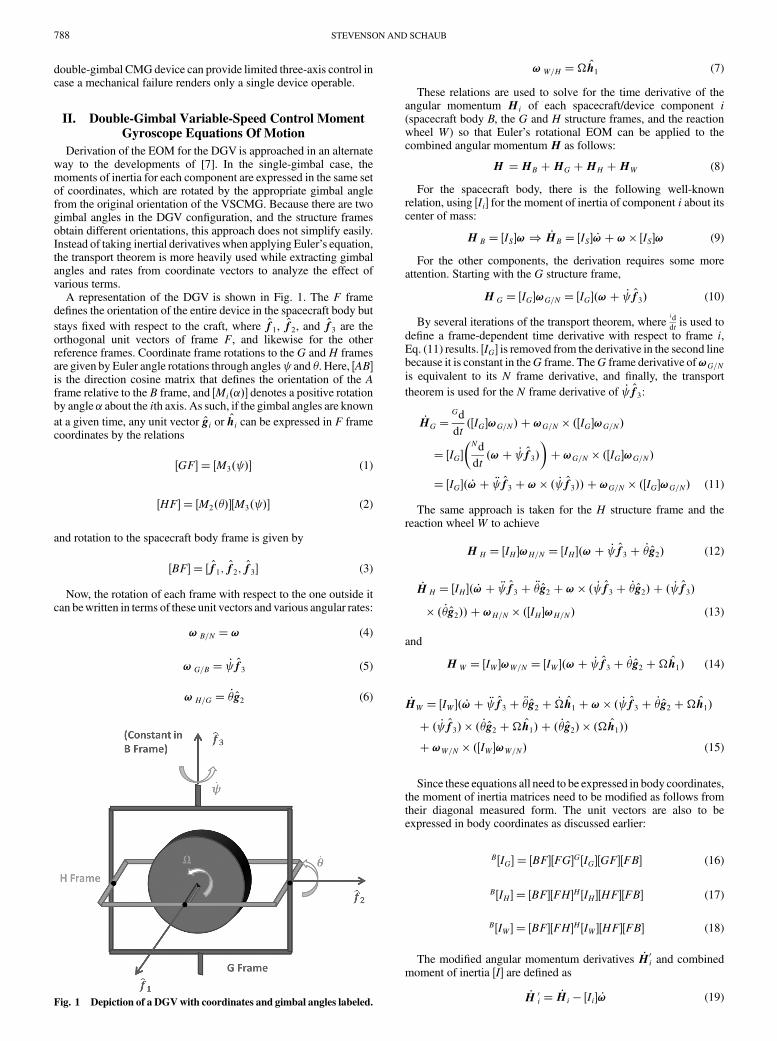
A representation of the DGV is shown in Fig. 1. The F framedefines the orientation of the entire device in the spacecraft body but
stays fixed with respect to the craft, where f1, f2, and f3 are theorthogonal unit vectors of frame F, and likewise for the otherreference frames. Coordinate frame rotations to the G andH framesare given by Euler angle rotations through angles and �. Here, �AB�is the direction cosine matrix that defines the orientation of the Aframe relative to the B frame, and �Mi���� denotes a positive rotationby angle � about the ith axis. As such, if the gimbal angles are known
at a given time, any unit vector gi or hi can be expressed in F framecoordinates by the relations
�GF� � �M3� �� (1)
�HF� � �M2�����M3� �� (2)
and rotation to the spacecraft body frame is given by
�BF� � �f1; f2; f3� (3)
Now, the rotation of each frame with respect to the one outside itcan bewritten in terms of these unit vectors and various angular rates:
! B=N �! (4)
! G=B � _ f3 (5)
! H=G � _�g2 (6)
!W=H ��h1 (7)
These relations are used to solve for the time derivative of theangular momentum Hi of each spacecraft/device component i(spacecraft body B, the G and H structure frames, and the reactionwheel W) so that Euler’s rotational EOM can be applied to thecombined angular momentumH as follows:
H �HB �HG �HH �HW (8)
For the spacecraft body, there is the following well-knownrelation, using �Ii� for the moment of inertia of component i about itscenter of mass:
H B � �IS�!) _HB � �IS� _!�! � �IS�! (9)
For the other components, the derivation requires some moreattention. Starting with the G structure frame,
H G � �IG�!G=N � �IG��!� _ f3� (10)
By several iterations of the transport theorem, whereid
dtis used to
define a frame-dependent time derivative with respect to frame i,Eq. (11) results. �IG� is removed from the derivative in the second linebecause it is constant in theG frame. TheG frame derivative of!G=Nis equivalent to its N frame derivative, and finally, the transport
theorem is used for the N frame derivative of _ f3:
_HG �Gd
dt��IG�!G=N� �!G=N � ��IG�!G=N�
� �IG��Nd
dt�!� _ f3�
��!G=N � ��IG�!G=N�
� �IG�� _!� � f3 �! � � _ f3�� �!G=N � ��IG�!G=N� (11)
The same approach is taken for the H structure frame and thereaction wheelW to achieve
H H � �IH �!H=N � �IH ��!� _ f3 � _�g2� (12)
_H H � �IH �� _!� � f3 � ��g2 �! � � _ f3 � _�g2� � � _ f3�
� � _�g2�� �!H=N � ��IH�!H=N� (13)
and
HW � �IW �!W=N � �IW ��!� _ f3 � _�g2 ��h1� (14)
_HW � �IW �� _!� � f3 � ��g2 � _�h1 �! � � _ f3 � _�g2 ��h1�
� � _ f3� � � _�g2 ��h1� � � _�g2� � ��h1���!W=N � ��IW �!W=N� (15)
Since these equations all need to be expressed in body coordinates,the moment of inertia matrices need to be modified as follows fromtheir diagonal measured form. The unit vectors are also to beexpressed in body coordinates as discussed earlier:
B�IG� � �BF��FG�G�IG��GF��FB� (16)
B�IH � � �BF��FH�H �IH ��HF��FB� (17)
B�IW � � �BF��FH�H �IW ��HF��FB� (18)
The modified angular momentum derivatives _H0i and combinedmoment of inertia �I� are defined as
_H 0i � _Hi � �Ii� _! (19)Fig. 1 Depiction of a DGVwith coordinates and gimbal angles labeled.
788 STEVENSON AND SCHAUB
�I� � �IS� � �IG� � �IH � � �IW � (20)
The full EOM of a DGV then become
�I� _!��! � �IS�!� _H0G � _H0H � _H0W �L (21)
Note that the gimbal rates can be isolated from every term inEqs. (11), (13), and (15), because they are scalars. The cross-productterms also contain the gimbal rates, including cross-coupled term.These will be expanded for the control law derivation, resulting infurther simplification that is not necessary for simulation of theEOM. If the DGV is not located at the center of mass of thespacecraft, the offcenter inertia components can be incorporated inthe spacecraft inertia �IS� using the parallel axis theorem [15]. �IS�remains a constantmatrix in theB frame evenwith the offcenterDGVinertia added, so Eq. (9) holds.
III. Equations of Motion Verification
The rotation of a spacecraft with one DGV is simulated by
propagating the state vector x� ��;!; ; _ ; �; _�;��T usingEq. (21).Modified Rodriguez parameters (MRPs) are used to define thespacecraft attitude, denoted by � [3,16,17]. The gimbal and wheel
accelerations � , ��, and _� are specified by a determined control law,assuming a servoloop is implemented by the motors. The resultingmotor torques ui on the wheel W, the H structure frame (innergimbal), and the G structure frame (outer gimbal) can then befound by
�HF��FB��B _HW� �H uW
24
35 (22)
�GF��FB��B _HH � B _HW� �G
uH
24
35 (23)
�FB��B _HG � B _HH � B _HW� �F uG
24
35 (24)
A good check to see whether the simulation is running correctly isto compare the numerical derivate of the analytical kinetic energyequation (25) and the analytical expression for the kinetic energy rateequation (26) according to the work-energy-rate principle [15]:
T � 12!TB=N �IS�!B=N � 1
2!TG=N �IG�!G=N � 1
2!TH=N �IH �!H=N
� 12!TW=N �IW �!W=N (25)
_T �!TB=NL� _ uG � _�uH ��uW (26)
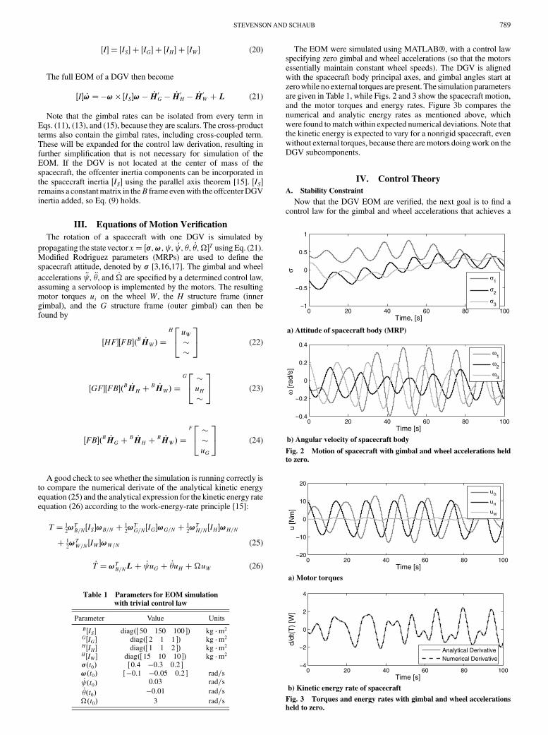
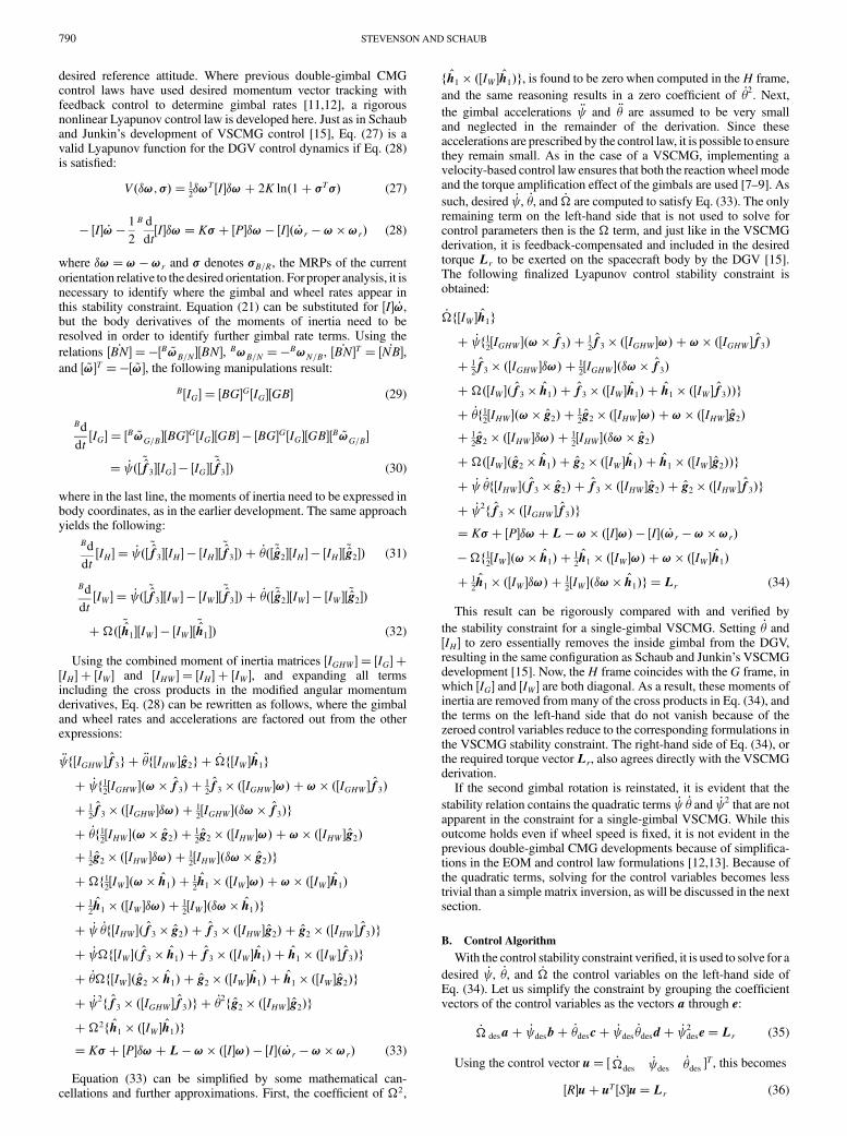
The EOM were simulated using MATLAB®, with a control lawspecifying zero gimbal and wheel accelerations (so that the motorsessentially maintain constant wheel speeds). The DGV is alignedwith the spacecraft body principal axes, and gimbal angles start atzerowhile no external torques are present. The simulation parametersare given in Table 1, while Figs. 2 and 3 show the spacecraft motion,and the motor torques and energy rates. Figure 3b compares thenumerical and analytic energy rates as mentioned above, whichwere found tomatchwithin expected numerical deviations. Note thatthe kinetic energy is expected to vary for a nonrigid spacecraft, evenwithout external torques, because there are motors doingwork on theDGV subcomponents.
IV. Control Theory
A. Stability Constraint
Now that the DGV EOM are verified, the next goal is to find acontrol law for the gimbal and wheel accelerations that achieves a
Table 1 Parameters for EOM simulation
with trivial control law
Parameter Value Units
B�IS� diag�� 50 150 100 �� kg m2
G�IG� diag�� 2 1 1 �� kg m2
H �IH � diag�� 1 1 2 �� kg m2
H �IW � diag�� 15 10 10 �� kg m2
��t0� � 0:4 �0:3 0:2 �!�t0� � �0:1 �0:05 0:2 � rad=s_ �t0� 0.03 rad=s_��t0� �0:01 rad=s
��t0� 3 rad=s
0 20 40 60 80 100−1
−0.5
0
0.5
1
Time, [s]
σ
σ1
σ2
σ3
a) Attitude of spacecraft body (MRP)
0 20 40 60 80 100−0.4
−0.2
0
0.2
0.4
Time [s]
ω [r
ad/s
]
ω1
ω2
ω3
b) Angular velocity of spacecraft body
Fig. 2 Motion of spacecraft with gimbal and wheel accelerations heldto zero.
0 20 40 60 80 100−20
−10
0
10
20
Time [s]
u [N
m]
uG
uH
uW
a) Motor torques
0 20 40 60 80 100−4
−2
0
2
4
Time [s]
d/dt
(T)
[W]
Analytical DerivativeNumerical Derivative
b) Kinetic energy rate of spacecraft
Fig. 3 Torques and energy rates with gimbal and wheel accelerations
held to zero.
STEVENSON AND SCHAUB 789
desired reference attitude. Where previous double-gimbal CMGcontrol laws have used desired momentum vector tracking withfeedback control to determine gimbal rates [11,12], a rigorousnonlinear Lyapunov control law is developed here. Just as in Schauband Junkin’s development of VSCMG control [15], Eq. (27) is avalid Lyapunov function for the DGV control dynamics if Eq. (28)is satisfied:
V��!; �� � 12�!T �I��!� 2K ln�1� �T�� (27)
� �I� _!� 1
2
B d
dt�I��!� K� � �P��! � �I�� _!r � ! �!r� (28)
where �!�! � !r and � denotes �B=R, the MRPs of the currentorientation relative to the desired orientation. For proper analysis, it isnecessary to identify where the gimbal and wheel rates appear inthis stability constraint. Equation (21) can be substituted for �I� _!,but the body derivatives of the moments of inertia need to beresolved in order to identify further gimbal rate terms. Using the
relations � _BN� � ��B ~!B=N ��BN�, B!B=N ��B!N=B, � _BN�T � � _NB�,and � ~!�T ��� ~!�, the following manipulations result:
B�IG� � �BG�G�IG��GB� (29)
Bd
dt�IG� � �B ~!G=B��BG�G�IG��GB� � �BG�G�IG��GB��B ~!G=B�
� _ �� ~f3��IG� � �IG��~f3�� (30)
where in the last line, the moments of inertia need to be expressed inbody coordinates, as in the earlier development. The same approachyields the following:
Bd
dt�IH � � _ �� ~f3��IH� � �IH ��
~f3�� � _��� ~g2��IH � � �IH �� ~g2�� (31)
Bd
dt�IW � � _ �� ~f3��IW � � �IW ��
~f3�� � _��� ~g2��IW � � �IW �� ~g2��
���� ~h1��IW � � �IW ��~h1�� (32)
Using the combined moment of inertia matrices �IGHW � � �IG� ��IH� � �IW � and �IHW � � �IH � � �IW �, and expanding all termsincluding the cross products in the modified angular momentumderivatives, Eq. (28) can be rewritten as follows, where the gimbaland wheel rates and accelerations are factored out from the otherexpressions:
� f�IGHW �f3g � ��f�IHW �g2g � _�f�IW �h1g
� _ f12�IGHW ��! � f3� � 1
2f3 � ��IGHW �!� �! � ��IGHW �f3�
� 12f3 � ��IGHW ��!� � 1
2�IGHW ���! � f3�g
� _�f12�IHW ��! � g2� � 1
2g2 � ��IHW �!� �! � ��IHW �g2�
� 12g2 � ��IHW ��!� � 1
2�IHW ���! � g2�g
��f12�IW ��! � h1� � 1
2h1 � ��IW �!� �! � ��IW �h1�
� 12h1 � ��IW ��!� � 1
2�IW ���! � h1�g
� _ _�f�IHW ��f3 � g2� � f3 � ��IHW �g2� � g2 � ��IHW �f3�g
� _ �f�IW ��f3 � h1� � f3 � ��IW �h1� � h1 � ��IW �f3�g
� _��f�IW ��g2 � h1� � g2 � ��IW �h1� � h1 � ��IW �g2�g
� _ 2ff3 � ��IGHW �f3�g � _�2fg2 � ��IHW �g2�g
��2fh1 � ��IW �h1�g� K� � �P��!�L � ! � ��I�!� � �I�� _!r � ! �!r� (33)
Equation (33) can be simplified by some mathematical can-cellations and further approximations. First, the coefficient of �2,
fh1 � ��IW �h1�g, is found to be zero when computed in theH frame,
and the same reasoning results in a zero coefficient of _�2. Next,
the gimbal accelerations � and �� are assumed to be very smalland neglected in the remainder of the derivation. Since theseaccelerations are prescribed by the control law, it is possible to ensurethey remain small. As in the case of a VSCMG, implementing avelocity-based control law ensures that both the reactionwheelmodeand the torque amplification effect of the gimbals are used [7–9]. As
such, desired _ , _�, and _� are computed to satisfy Eq. (33). The onlyremaining term on the left-hand side that is not used to solve forcontrol parameters then is the � term, and just like in the VSCMGderivation, it is feedback-compensated and included in the desiredtorque Lr to be exerted on the spacecraft body by the DGV [15].The following finalized Lyapunov control stability constraint isobtained:
_�f�IW �h1g
� _ f12�IGHW ��! � f3� � 1
2f3 � ��IGHW �!� �! � ��IGHW �f3�
� 12f3 � ��IGHW ��!� � 1
2�IGHW ���! � f3�
����IW ��f3 � h1� � f3 � ��IW �h1� � h1 � ��IW �f3��g
� _�f12�IHW ��! � g2� � 1
2g2 � ��IHW �!� �! � ��IHW �g2�
� 12g2 � ��IHW ��!� � 1
2�IHW ���! � g2�
����IW ��g2 � h1� � g2 � ��IW �h1� � h1 � ��IW �g2��g
� _ _�f�IHW ��f3 � g2� � f3 � ��IHW �g2� � g2 � ��IHW �f3�g
� _ 2ff3 � ��IGHW �f3�g� K� � �P��!� L � ! � ��I�!� � �I�� _!r � ! �!r�
��f12�IW ��! � h1� � 1
2h1 � ��IW �!� �! � ��IW �h1�
� 12h1 � ��IW ��!� � 1
2�IW ���! � h1�g � Lr (34)
This result can be rigorously compared with and verified by
the stability constraint for a single-gimbal VSCMG. Setting _� and�IH � to zero essentially removes the inside gimbal from the DGV,resulting in the same configuration as Schaub and Junkin’s VSCMGdevelopment [15]. Now, theH frame coincides with the G frame, inwhich �IG� and �IW � are both diagonal. As a result, these moments ofinertia are removed frommany of the cross products in Eq. (34), andthe terms on the left-hand side that do not vanish because of thezeroed control variables reduce to the corresponding formulations inthe VSCMG stability constraint. The right-hand side of Eq. (34), orthe required torque vectorLr, also agrees directly with the VSCMGderivation.
If the second gimbal rotation is reinstated, it is evident that the
stability relation contains the quadratic terms _ _� and _ 2 that are notapparent in the constraint for a single-gimbal VSCMG. While thisoutcome holds even if wheel speed is fixed, it is not evident in theprevious double-gimbal CMG developments because of simplifica-tions in the EOM and control law formulations [12,13]. Because ofthe quadratic terms, solving for the control variables becomes lesstrivial than a simple matrix inversion, as will be discussed in the nextsection.
B. Control Algorithm
With the control stability constraint verified, it is used to solve for a
desired _ , _�, and _� the control variables on the left-hand side ofEq. (34). Let us simplify the constraint by grouping the coefficientvectors of the control variables as the vectors a through e:
_� desa� _ desb� _�desc� _ des_�desd� _ 2
dese� Lr (35)
Using the control vector u� � _�des_ des
_�des �T, this becomes
�R�u� uT �S�u�Lr (36)
790 STEVENSON AND SCHAUB

where matrices �R� and �S� are [3 � 1] and [3 � 3], respectively, buttheir entries are [3 � 1] vectors as follows:
�R� � �a b c � (37)
�S� �0 0 00 e 1
2d
0 12d 0
24
35 (38)
This nonlinear matrix equation cannot be solved analyticallyfor u; instead, a Newton–Raphson (N–R) iteration is used to find theroot of the relation
f �u� � �R�u� uT �S�u� Lr (39)
For the initial guess, the control vector is solvedwith the quadraticterms neglected:
u 0 � �R��1Lr (40)
Incremental corrections are made until the error jf�u�j issufficiently small using
u � u0 � �J��1f�u� (41)
where �J� is the Jacobian of f with u:
�J� � �a b� u3d� 2u2e c� u2d � (42)
In the numerical control simulation presented later in this paper,where no singularities are encountered, the initial error jf�u0�j staysalmost three orders ofmagnitude below the required torque size jLrj,and nomore than two iterations are required to achieve an accuracy of10�9 N m in jf�u�j.When singularities are not avoided, the amountof necessary iterations can become much larger.
The wheel acceleration from the control vector u can beimplemented directly in themotor servo, but to determine the desiredgimbal accelerations for their motor servos, a proportional controlwith feedforward term is required:
_� srv � _�des (43)
� srv ��K _ � _ � _ des� � � des (44)
�� srv ��K _�� _� � _�des� � ��des (45)
where
� des �_ des�t� � _ des�t� tstep�
tstep(46)
�� des �_�des�t� � _�des�t� tstep�
tstep(47)
As with CMG gimbal rate servocontrols solutions, exact controlis not expected with this steering law because of the gimbalacceleration terms that are neglected. The best results are achieved
when gimbal accelerations � and �� are kept small, a similarrequirement as for effective CMG control.
C. Control Singularities
The dominant terms from Eq. (33) that appear in the steeringlaw are
_�f�IW �h1g � _ �f�IW ��f3 � h1� � f3 � ��IW �h1�
� h1 � ��IW �f3�g � _��f�IW ��g2 � h1� � g2 � ��IW �h1�
� h1 � ��IW �g2�g (48)
The second two lines are equivalent to the torque amplificationterm in the VSCMG control law, since a small gimbal rate canproduce a large torque quantity when� is large. If the operations inEq. (48) are performed in the H frame, and the wheel moment ofinertia matrix is expressed as
H �IW � �IW1
0 00 IW2
00 0 IW3
24
35 (49)
the result is
_�IW2h1 � _ ��IW1
� IW2� IW3
� cos �h2� _���IW1
� IW2� IW3
�h3 (50)
It is evident here that the dominant terms of this steering law span
the entire vector space, except when �� 90 deg and the _ � termvanishes. This is logical because, at that configuration, the twogimbal frames line up and the torques from the outer gimbal motorand the wheel motor are collinear. There are other terms in the avector of Eq. (36), but they do not contain � and are thus much
smaller. The inclusion of the _ _� term in the control law does notalleviate the singularity problem either because its associated vector
can be shown to contain only components in the h1 and h3 directions.There is a chance the system pushes through this singularity, but thesteering law is certainly not robust with a single DGVas there is nonull space to avoid the singularity. Combined with another simplecontrol device, such as a reaction wheel to avoid singularities, asingle DGV could still provide effective spacecraft attitude control.
D. Control Simulation
The control law discussed above is implemented to track anarbitrary sinusoidal attitude reference trajectory. Spacecraft param-eters and initial conditions are the same as in Table 1 with theexception of ��t0� and the control parameters that are shown inTable 2.
Figure 4 shows that the velocity-based steering law does a verysuccessful job of tracking the desired attitude, as long as singularitieswhere � approaches�90 deg are avoided. It is evident from Fig. 5athat this is the case with these simulation parameters (wheel speed isnot shown, but it stays close to 100 rad=s). In the beginning of thesimulation, the control law requires largemotor torques to correct theinitial attitude and velocity errors. In reality, the motors mightsaturate from this aggressive control, in which case time-dependentgains could be implemented to keep the desired servo accelerationswithin certain bounds.
As the gimbal frames approach the orientationwhere they are linedup, their motors see higher torques to resist each others’motion. Thiscan be seen in the simulation in Fig. 6a, where uG and uW increase
Table 2 Parameters for reference tracking
simulation with nonlinear control law
Parameter Value Units
��t0� 100 rad=sK 100�P� diag�� 100 100 100 ��K _ 10
K _� 10
STEVENSON AND SCHAUB 791

together and decrease together at roughly 35 and 80 s, respectively.This coincides with � nearing �90 deg in Fig. 5a.
The error in the initial N–R guess, jf�u0�j, and the number ofiterations required to bring this error down to 10�9 N m are shownin Fig. 7. Thus, while the control formulation requires iteratingnumerically to solve for DGV control variables from a quadraticmatrix equation, this process is achieved very rapidly with only oneto two iteration steps. Moreover, the errors in the computed desiredtorque stay within 0.15% without N–R iteration, suggesting thatacceptable control would be achieved in this simulation withoutconsideration of the quadratic control parameter terms. The compu-tational cost of theN–R iteration represents only 2.08%of the controlupdate calculation time, so there is no large detriment to determiningthe exact solution. When the DGV system approaches a singularity,however, the error and N–R iterations quickly increase, and morebenefit is achieved by solving for the nonlinear parameters. In aflight-ready satellite, however, other actuators would be included toensure that control singularities are avoided.
V. Conclusions
The goal of this investigation is to derive the full EOM of a DGVand determine whether a single such device can provide full attitudecontrol of a spacecraft and employ the torque amplification seen insingle-gimbal devices. The control law dynamics show that thistorque amplification is indeed evident, but the DGV can encountercontrol singularities that prevent robust control from a single DGVdevice alone. The nonlinear nature of the stability constraint requiresa novel approach in the control algorithm, namely, using a N–Rsolving method to acquire the desired control parameters. Since highaccuracy resulted with only two iterations from the initial controlguess using feedback compensation of the nonlinear terms, it isdeduced that the coefficients of the nonlinear terms are generallysmall. When singularities where the gimbal frames line up with eachother are avoided, the nonlinear control algorithm achieves veryaccurate tracking of a reference attitude trajectory. Future work willattempt to achieve robust control and singularity avoidance with a
0 20 40 60 80 100−8
−6
−4
−2
0
2
Time [s]
Gim
bal A
ngle
s [r
ad]
ψθ
a) Gimbal angles
0 20 40 60 80 100−0.6
−0.4
−0.2
0
0.2
0.4
Time [s]
Gim
bal R
ates
[rad
/s]
ψdot
θdot
b) Gimbal rates
Fig. 5 Gimbal and wheel angles and rates with velocity-based
steering law.
0 20 40 60 80 100−0.4
−0.2
0
0.2
0.4
Time [s]
σσ
1σ
2 σ3
SpacecraftReference
a) Attitude of spacecraft body (MRP)
0 20 40 60 80 100−0.4
−0.2
0
0.2
0.4
ω1
ω2
ω3
Time [s]
ω [r
ad/s
]
SpacecraftReference
b) Angular velocity of spacecraft bodyFig. 4 Motion of spacecraft and reference trajectory with velocity-based steering law.
0 20 40 60 80 1000
0.5
1
1.5x 10
−3
|f(u 0)|
/|Lr| [
Nm
]
Time [s]
a) Percent error in initial newton-raphson guess for L r
0 20 40 60 80 1000
1
2
3
n
Time [s]
b) Number of newton-raphson iterations
Fig. 7 N–R initial guess error and number of iterations.
0 20 40 60 80 100
−5
0
5
Time [s]
u [N
m]
uG
uH
uW
a) Motor torques
0 20 40 60 80 100−200
0
200
400
d/dt
(T)
[W]
Time [s]
b) Kinetic energy rate of spacecraft
Fig. 6 Torques and spacecraft energy rates with velocity-based
steering law.
792 STEVENSON AND SCHAUB
multi-DGV cluster, using the null space that results from the system’sextra degrees of freedom.
Acknowledgment
This material is based upon work supported by the NationalScience Foundation Graduate Research Fellowship under grantnumber (1000100047).
References
[1] Tsiotras, P., Shen, H., and Hall, C., “Satellite Attitude Control andPower Tracking with Energy/Momentum Wheels,” Journal of
Guidance, Control, and Dynamics, Vol. 24, No. 1, 2001, pp. 23–24.doi:10.2514/2.4705
[2] Richie, D. J., Lappas, V. J., and Prassinos, G., “Sizing/Optimizationof a Small Satellite Energy Storage and Attitude Control System,”Journal of Spacecraft and Rockets, Vol. 44, No. 4, July–Aug. 2007,pp. 940–952.doi:10.2514/1.25134
[3] Schaub, H., “Novel Coordinates for Nonlinear Multibody Motion withApplications to Spacecraft Dynamics and Control,” Ph.D. Dissertation,Texas A & M Univ., College Station, TX, 1998.
[4] Yoon, H., and Tsiotras, P., “Spacecraft Adaptive Attitude andPower Tracking with Variable Speed Control Moment Gyroscopes,”Journal of Guidance, Control, and Dynamics, Vol. 25, No. 6, 2002,pp. 1081–1090.doi:10.2514/2.4987
[5] Yoon, H., and Tsiotras, P., “Singularity Analysis of Variable SpeedControlMomentGyros,” Journal ofGuidance, Control, andDynamics,Vol. 27, No. 3, 2004, pp. 374–386.doi:10.2514/1.2946
[6] Richie, D. J., Lappas, V. J., and Prassinos, G., “A Practical SmallSatellite Variable-Speed Control Moment Gyroscope For CombinedEnergy Storage and Attitude Control,” AAS/AIAA AstrodynamicsSpecialist Conference, Honolulu, HI, AIAA Paper 2008-7503,18–21 Aug. 2008.
[7] Schaub, H., R. Vadali, S., and Junkins, J. L., “Feedback Control Lawfor Variable Speed Control Moment Gyroscopes,” Journal of the
Astronautical Sciences, Vol. 46, No. 3, July–Sept. 1998, pp. 307–328.[8] Schaub, H., and Junkins, J. L., “Singularity Avoidance Using Null
Motion and Variable-Speed Control Moment Gyros,” Journal of
Guidance, Control, and Dynamics, Vol. 23, No. 1, Jan.–Feb. 2000,pp. 11–16.doi:10.2514/2.4514
[9] McMahon, J., and Schaub, H., “Simplified Singularity AvoidanceUsing Variable Speed Control Moment Gyroscope Nullmotion,”AAS/AIAA Spaceflight Mechanics Meeting, San Diego, CA,American Astronautical Soc. Paper 10-210, Springfield, VA,14–18 Feb. 2010.
[10] O’Conner, B. J., and Morine, L., “A Description of the CMG and itsApplication to Space Vehicle Control,” Journal of Spacecraft and
Rockets, Vol. 6, No. 3, 1969, pp. 225–231.doi:10.2514/3.29577
[11] Kennel, H. F., “A Control Law for Double-Gimbaled Control MomentGyros Used for Space Vehicle Attitude Control,” NASATM X-64536,7 Aug. 1970.
[12] Kennel, H. F., “Steering Law for Parallel Mounted Double-GimbaledControl Moment Gyros,” NASATM X-64930, Feb. 1975.
[13] Ahmed, J., and Bernstein, D., “Adaptive Control of Double-GimbalControl-Moment Gyro with Unbalanced Rotor,” Journal of Guidance,Control, and Dynamics, Vol. 25, No. 1, Jan.–Feb. 2002, pp. 105–115.doi:10.2514/2.4855
[14] Gurrisi, C., Seidel, R., Dickerson, S., Didziulis, S., Frantz, P.,and Ferguson, K., “Space Station Control Moment GyroscopeLessons Learned,” Proceedings of the 40th Aerospace Mechanisms
Symposium, NASA NASA/CP-2010-216272, Kennedy Space Center,12–14 May 2010.
[15] Schaub, H., and Junkins, J. L., Analytical Mechanics of Space Systems,2nd ed., AIAA Education Series, AIAA, Reston, VA, Oct. 2009,pp. 178–188, 408–430.
[16] Schaub, H., and Junkins, J. L., “Stereographic Orientation Parametersfor Attitude Dynamics: AGeneralization of the Rodrigues Parameters,”Journal of the Astronautical Sciences, Vol. 44, No. 1, 1996, pp. 1–19.
[17] Schaub, H., and Junkins, J. L., “MATLAB Toolbox for Rigid BodyKinematics,” Proceedings of the AAS/AIAA Space Flight MechanicsMeeting, Breckenridge, CO, American Astronautical Soc. Paper 99-139, Springfield, VA, 7–10 Feb. 1999, pp. 549–560.
STEVENSON AND SCHAUB 793