NONLINEAR ANALYSIS OF OFFSHORE STRUCTURES UNDER WAVE LOADINGS · NONLINEAR ANALYSIS OF OFFSHORE...
15
Journal of Engineering Sciences, Assiut University, Vol. 40, No. 3, pp.673- 687, May 2012 673 NONLINEAR ANALYSIS OF OFFSHORE STRUCTURES UNDER WAVE LOADINGS Shehata E. Abdel Raheem 1 , Elsayed M. A. Abdel Aal 2 , Aly G. A. Abdel Shafy 3 and Fayez K. Abdel Seed 3 1.Assoc. Prof. of Earthquake, Structural and Geotechnical Engineering, Taibah University, KSA. On leave; Faculty of Engineering, Assiut University [email protected] 2. Senior Off-Shore Structural Engineer, Egypt Gas Company. 3. Prof. of Structural Engineering, Civil Engineering, Faculty of Engineering, Assiut University. (Received January 21, 2012 Accepted February 21, 2012) The structural design requirements of an offshore platform subjected wave induced forces and moments in the jacket can play a major role in the design of the offshore structures. For an economic and reliable design; good estimation of wave loadings are essential. A nonlinear response analysis of a fixed offshore platform under wave loading is presented, the structure is discretized using the finite element method, wave force is determined according to linearized Morison equation. Hydrodynamic loading on horizontal and vertical tubular members and the dynamic response of fixed offshore structure together with the distribution of displacement, axial force and bending moment along the leg are investigated for regular and extreme conditions, where the structure should keep production capability in conditions of the one year return period wave and must be able to survive the 100 year return period storm conditions. The result of the study shows that the nonlinear response investigation is quite crucial for safe design and operation of offshore platform. KEYWORDS: Offshore Structures, Sea waves, Nonlinear Analysis, Finite Element Analysis, Wave-Structure Interaction. 1. INTRODUCTION The total number of offshore platform in various bays, gulf and oceans of the world is increasing year by year, most of which are of fixed jacket-type platforms located in 30 m to 200 m depth for oil and gas exploration purposes. Fixed offshore platforms are subjected to different environmental loads during their lifetime. These loads are imposed on platforms through natural phenomena such as wind, current, wave, earthquake, snow and earth movement. Among various types of environmental loading, wave forces loading is dominated loads. According to API-RP2A 1997 (2.2) [1-3], environmental loads, with the exception of earthquake, should be combined in a manner consistent with the probability of their simultaneous occurrence during the loading condition being considered. In addition DNV 1980 (5.2.4) [4] suggests that loads due to earthquake normally need not be considered to act simultaneously with other environmental loads. It is necessary to design an offshore structure such that it
Transcript of NONLINEAR ANALYSIS OF OFFSHORE STRUCTURES UNDER WAVE LOADINGS · NONLINEAR ANALYSIS OF OFFSHORE...

Journal of Engineering Sciences, Assiut University, Vol. 40, No. 3, pp.673- 687, May 2012
673
NONLINEAR ANALYSIS OF OFFSHORE STRUCTURES UNDER WAVE LOADINGS
Shehata E. Abdel Raheem1, Elsayed M. A. Abdel Aal 2, Aly G. A. Abdel Shafy3 and Fayez K. Abdel Seed 3 1.Assoc. Prof. of Earthquake, Structural and Geotechnical Engineering,
Taibah University, KSA. On leave; Faculty of Engineering, Assiut
University
2. Senior Off-Shore Structural Engineer, Egypt Gas Company.
3. Prof. of Structural Engineering, Civil Engineering, Faculty of
Engineering, Assiut University.
(Received January 21, 2012 Accepted February 21, 2012)
The structural design requirements of an offshore platform subjected wave
induced forces and moments in the jacket can play a major role in the
design of the offshore structures. For an economic and reliable design;
good estimation of wave loadings are essential. A nonlinear response
analysis of a fixed offshore platform under wave loading is presented, the
structure is discretized using the finite element method, wave force is
determined according to linearized Morison equation. Hydrodynamic
loading on horizontal and vertical tubular members and the dynamic
response of fixed offshore structure together with the distribution of
displacement, axial force and bending moment along the leg are
investigated for regular and extreme conditions, where the structure should
keep production capability in conditions of the one year return period wave
and must be able to survive the 100 year return period storm conditions.
The result of the study shows that the nonlinear response investigation is
quite crucial for safe design and operation of offshore platform.
KEYWORDS: Offshore Structures, Sea waves, Nonlinear Analysis,
Finite Element Analysis, Wave-Structure Interaction.
1. INTRODUCTION
The total number of offshore platform in various bays, gulf and oceans of the world is
increasing year by year, most of which are of fixed jacket-type platforms located in 30
m to 200 m depth for oil and gas exploration purposes. Fixed offshore platforms are
subjected to different environmental loads during their lifetime. These loads are
imposed on platforms through natural phenomena such as wind, current, wave,
earthquake, snow and earth movement. Among various types of environmental loading,
wave forces loading is dominated loads. According to API-RP2A 1997 (2.2) [1-3],
environmental loads, with the exception of earthquake, should be combined in a
manner consistent with the probability of their simultaneous occurrence during the
loading condition being considered. In addition DNV 1980 (5.2.4) [4] suggests that
loads due to earthquake normally need not be considered to act simultaneously with
other environmental loads. It is necessary to design an offshore structure such that it
Shehata E. Abdel Raheem1, Elsayed M. A. Abdel Aal
2, … 674
can respond to moderate environmental loads without damage and is capable of
resisting severe environmental loads without seriously endangering the occupants. The
standard design of the structure is carried out using the allowable stress method.
However, it is important to clarify the effects on nonlinear responses for an offshore
structure under the severe wave conditions.
Offshore structures may be analyzed using static or dynamic analysis methods.
Static analysis methods are sufficient for structures, which are rigid enough to neglect
the dynamic forces associated with the motion under the time-dependent environmental
loadings. On the other hand, structures which are flexible due to their particular form
and which are to be used in deep sea must be checked for dynamic loads. Dynamic
analysis is particularly important for waves of moderate heights as they make the
greatest contribution to fatigue damage and reliability of offshore structures. The
dynamic response evaluation due to wave forces has significant roles on the reliable
design of the offshore structure [5].
In the design and analysis of fixed offshore structures many nonlinear physical
quantities and mechanisms exist that are difficult to quantify and interpret in relation to
hydrodynamic loading. The calculation of the wave loads on vertical tubular members
is always of major concern to engineers, especially recently when such studies are
motivated by the need to build solid offshore structures in connection with oil and
natural gas productions. The effects of various wave patterns on offshore structures
have been investigated by numerous researchers in the past [6 - 18].
This research summarizes the nonlinear dynamic analysis of a 3-D model of a
typical Jacket-Type platform, which is installed in Suez gulf, Red sea, 1988 and
presents the numerical investigation on dynamic behavior of an offshore structure
under wave loads. Wave loading is applied to a full jacket structure by Stokes 5th order
wave methods with gravity loads also present. The analysis considers various
nonlinearities produced due to change in the nonlinear hydrodynamic drag force. The
wave forces on the elements of the offshore structure are calculated using Airy's wave
theory and Morison's equation. Numerical results are presented for various
combinations of typical sea states. Natural periods and mode shapes of the system are
calculated. The results of these investigations highlight the importance of accurately
simulating nonlinear effects in fixed offshore structures from the point of view of safe
design and operation of such systems.
2. DESIGN CODES OF PRACTICE
The majority of the world’s platforms have been designed according to the different
editions of Recommended Practice by The American Petroleum Institute (API), which
until 1993 has been in Working Stress Design (WSD) format. The 20th edition (1993)
was also issued in Load and Resistance Factor Design (LRFD) format, and was in 1997
supplemented with a section on re-qualification of offshore structures. American
Petroleum Institute (API) RP2A-LRFD, 1993 provisions provide characterization of
environmental load and design requirement for fixed offshore platform for use in
design, describe analytical methods to determine the forces induced in the platform
system by ground motions, and give guidance for sizing and configuring steel elements
for the design forces. The consideration of environmental loads are consist earthquake
loads in terms of earthquake ground motions, wind, wave and current loads. Design
NONLINEAR ANALYSIS OF OFFSHORE STRUCTURES UNDER … 675
methods for structures, members or components under static loads to avoid failure,
collapse, buckling are well defined in codes and standards, such equivalent codes in
other countries, whilst for offshore structures the design code used almost invariably is
API RP2A (API 1993).
3. SEA ENVIRONMENTAL LOADS
Water force can be classified as forces due to waves and forces due to current. Wind
blowing over the ocean’s surface drags water along with it, thus forming current and
generating waves. The forces induce by ocean waves on platform are dynamic in
nature. However, it is the accepted practice to design shallow water platforms by static
approach. As a water depth increases and/or platforms become flexible, dynamic effect
assume significance.
3.1 Waves and Hydrodynamic Loads
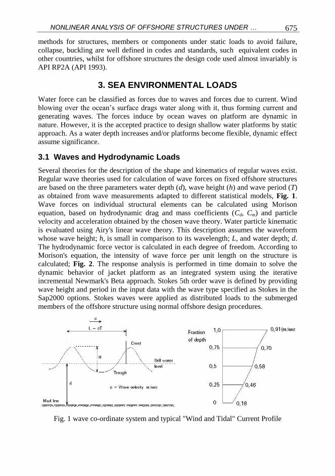
Several theories for the description of the shape and kinematics of regular waves exist.
Regular wave theories used for calculation of wave forces on fixed offshore structures
are based on the three parameters water depth (d), wave height (h) and wave period (T)
as obtained from wave measurements adapted to different statistical models, Fig. 1.
Wave forces on individual structural elements can be calculated using Morison
equation, based on hydrodynamic drag and mass coefficients (Cd, Cm) and particle
velocity and acceleration obtained by the chosen wave theory. Water particle kinematic
is evaluated using Airy's linear wave theory. This description assumes the waveform
whose wave height; h, is small in comparison to its wavelength; L, and water depth; d.
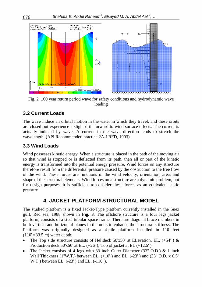
The hydrodynamic force vector is calculated in each degree of freedom. According to
Morison's equation, the intensity of wave force per unit length on the structure is
calculated; Fig. 2. The response analysis is performed in time domain to solve the
dynamic behavior of jacket platform as an integrated system using the iterative
incremental Newmark's Beta approach. Stokes 5th order wave is defined by providing
wave height and period in the input data with the wave type specified as Stokes in the
Sap2000 options. Stokes waves were applied as distributed loads to the submerged
members of the offshore structure using normal offshore design procedures.
Fig. 1 wave co-ordinate system and typical "Wind and Tidal" Current Profile
Shehata E. Abdel Raheem1, Elsayed M. A. Abdel Aal
2, … 676
Fig. 2 100 year return period wave for safety conditions and hydrodynamic wave
loading
3.2 Current Loads
The wave induce an orbital motion in the water in which they travel, and these orbits
are closed but experience a slight drift forward to wind surface effects. The current is
actually induced by wave. A current in the wave direction tends to stretch the
wavelength. (API Recommended practice 2A-LRFD, 1993)
3.3 Wind Loads
Wind possesses kinetic energy. When a structure is placed in the path of the moving air
so that wind is stopped or is deflected from its path, then all or part of the kinetic
energy is transformed into the potential energy pressure. Wind forces on any structure
therefore result from the differential pressure caused by the obstruction to the free flow
of the wind. These forces are functions of the wind velocity, orientation, area, and
shape of the structural elements. Wind forces on a structure are a dynamic problem, but
for design purposes, it is sufficient to consider these forces as an equivalent static
pressure.
4. JACKET PLATFORM STRUCTURAL MODEL
The studied platform is a fixed Jacket-Type platform currently installed in the Suez
gulf, Red sea, 1988 shown in Fig. 3, The offshore structure is a four legs jacket
platform, consists of a steel tubular-space frame. There are diagonal brace members in
both vertical and horizontal planes in the units to enhance the structural stiffness. The
Platform was originally designed as a 4-pile platform installed in 110 feet
(110' =33.5 m) water depth;
The Top side structure consists of Helideck 50'x50' at ELevation, EL. (+54' ) &
Production deck 50'x50' at EL. (+26' ); Top of jacket at EL (+12.5' ).
The Jacket consists of 4 legs with 33 inch Outer Diameter (33'' O.D.) & 1 inch
Wall Thickness (1''W.T.) between EL. (+10' ) and EL. (-23' ) and (33'' O.D. x 0.5''
W.T.) between EL. (-23' ) and EL. (-110' ).

NONLINEAR ANALYSIS OF OFFSHORE STRUCTURES UNDER … 677
In the splash zone area that is assumed to extend from EL. (-6' ) to EL. (+6' ) LAT.
(Lowest Astronomical Tide).
The jacket legs are horizontally braced with tubular members (8.625'' O.D. x
0.322'' W.T.) at elevations (+10' ); (10.75'' O.D. x 0.365'' W.T.) at elevations (-
23' ); (12.75'' O.D. x 0.375'' W.T.) at elevations (-62' ) and (14'' O.D. X 0.375''
W.T.) at elevations (-110' ).
In the vertical direction, the jacket is X-braced with tubular members (12.75'' O.D.
x 0.844'' W.T.) from EL. (+10' ) to EL. (-23' ) and (12.75'' O.D. x 0.375'' W.T.)
from EL. (-23' ) to EL. (-110' ). The platform is supported by 4 piles (30'' O.D. x
1.25'' W.T.).
Fig. 3 Sketch map of the platform model
5. ANALYSIS PROCEDURES
A finite element analysis is carried out under different types of wave loading. The hull
of jack up is relatively stiff compared to legs, so the structural model concentrates on
the accurate description of load deformation characteristics of the legs. The legs are
modeled by equivalent beam elements. Focus has been on the underlying mechanisms
of the global structural response. For the present analysis, dead loads include all fixed
items in the platform deck, jacket, and bridge structures. Live loads are defined as
movable loads and will be temporary in nature. A uniformly distributed live load
intensity of 50 psf "0.245 t/m2" is applied to Helideck area; 200 psf "0.978 t/m
2" is
applied to production deck area and cellar deck area.
The water depth in the location of installed platform is 110' (33.5 m).
Regarding to the information of waves height with the returning period of one year for
studied zone, a fifth order stokes wave theory with the height of 17 ft and the period of
6.5 sec used. A 100-years return wave with the height of 26 ft and the period of 8 sec

Shehata E. Abdel Raheem1, Elsayed M. A. Abdel Aal
2, … 678
was selected for the type of analysis that is normally used for safety checks. The wave
force is expressed using the Morison equation and the nonlinear relative-velocity
squared drag term is replaced by an equivalent linearized drag term.
The design force of most platforms is dominated by waves. A wave height of 1
or 100 years return period is the commonly used design criterion, which was extended
by employing the combination of the 100-year wave with the 100-year wind. American
Petroleum Institute (API RP 2A) recommends the following formula to calculate wind
force on offshore structures, The 100 year return period sustained wind at 30 feet
above LAT (lowest astronomical tide) shall be 70 mph (mile per hour), the wind may
act in any direction. The variation of wind speed with height is taken as varying with
height according to the power law.
Fig. 4 Finite element model Fig. 5 Jacket - deck connection nodes at level (+10 ft)
VZ = V30 (Z/30) X
Where VZ = Velocity at height Z feet (ft/sec); V30 = Velocity at height 30 feet
(ft/sec); Z is Height above LAT, (feet); X = 0.125; VZ shall not be less than V30. The
wind loads on the topsides and exposed part of the jackets shall be calculated based on
the topsides layout configurations to determine the shape coefficients.
6. NUMERICAL RESULTS AND DISCUSSIONS
The natural frequencies and vibration mode shapes are computed by eigenvalue
analysis. The values of natural frequencies are shown in Table 1 for up to the six mode
of vibration. The stress distribution within such a large structure is a dominant factor in
the design procedure of an offshore structure. To provide a more accurate and
effective design, a finite element model is employed herein to determine the internal
forces and displacements in an offshore leg under combined structural and wave
loadings. The vertical structural load is essentially a static load, while the lateral wave
loading fluctuates in time domain and is directly affected by the incident wave angle.

NONLINEAR ANALYSIS OF OFFSHORE STRUCTURES UNDER … 679
The module in this study is classical steel platform was built in 1988 at Gulf of
Suez in Egypt, Fig. 3. A 3D model had been generated for the platform using SAP
2000 computer software package. Secondary members that are not expected to
contribute much to the structure strength are not included in the model simulation (i.e.
ladders, grating, etc.) but their loads were reflected to the model. The right hand
Cartesian system is used with the Z-axis vertically upwards and the origin is located at
the Main water Level (MWL) as shown in Figs. 4 and 5. Table 2 lists the properties of
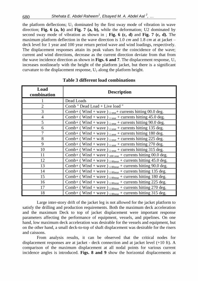
the studied. Different load combinations are applied to platform as shown in Table 3.
The straining actions and deflection results are investigated for jacket only because the
main important part in platform, which is supported under sea, water and subjected to
all environmental load and high costs to install it.
A parametric study of varying certain parameters of the wave, current loads to
study their effects on the internal forces distribution and platform displacement under
various combinations of structural and wave loadings is investigated. The Cd and Cm
values are considered as per API (2000) to be 0.65 and 1.6, respectively. The same
values of wave parameters are applied in three directions ±0o, ±45
o and ±90
o (X, XY,
and Y) with the associated current parameters having the same direction of wave
application, Table 3.
Table 1 Natural period and vibration mode
Modes 1st mode 2
nd mode 3
rd mode 4
th mode 5
th mode 6
th mode
Natural period (sec) 0.902 0.897 0.734 0.281 0.277 0.267
Vibration mode 1
st
Sway-X
1st
Sway-Y
1st
Torsion
2nd
Sway-X
2nd
Sway-Y
2nd
Torsion
Table 2 wave loading parameter values
Definitions
Water
depth
(MSL) ft
LAT
(MSL) ft
HAT
MSL) ft
tide
(ft)
Hmax.
(ft)
Tp
(sec)
1-year return period wave
for operating conditions
110' -6' 6'
3' 17' 6.5
100 year return period
wave for safety
conditions
5' 26' 8
6.1 Displacement Response of the Structure
To have a better understanding of the behavior over the entire height of the platform
jacket, the analysis was conducted for a 110 ft water depth for the maximum wind and
wave forces. Even though time series deflection of the platform were estimated, only
maximum deflection to each wave and wind forces are extracted. The deflection
responses along the platform jacket height to the wave loading of 1 year and 100 year
return period are shown in Figs. 6 and 7. It should be noted that the response
considered are deflection in global X- direction; U1 and Y-direction; U2. Fig. 6 shows
Shehata E. Abdel Raheem1, Elsayed M. A. Abdel Aal
2, … 680
the platform deflections; U1 dominated by the first sway mode of vibration in wave
direction; Fig. 6 (a, b) and Fig. 7 (a, b), while the deformation; U2 dominated by
second sway mode of vibration as shown in ; Fig. 6 (c, d) and Fig. 7 (c, d). The
maximum platform deflection in the wave direction is 1.0 cm and 1.8 cm at at jacket –
deck level for 1 year and 100 year return period wave and wind loadings, respectively.
The displacement responses attain its peak values for the coincidence of the wave;
current and wind directions, decrease as the current direction deviate from that from
the wave incidence direction as shown in Figs. 6 and 7. The displacement response, U1
increases nonlinearly with the height of the platform jacket, but there is a significant
curvature to the displacement response, U2 along the platform height.
Table 3 different load combinations
Load
combination Description
1 Dead Loads
2 Comb " Dead Load + Live load "
3 Comb+ ( Wind + wave ) 1 year+ currents hitting 00.0 deg.
4 Comb+ ( Wind + wave ) 1 year + currents hitting 45.0 deg.
5 Comb+ ( Wind + wave ) 1 year + currents hitting 90.0 deg.
6 Comb+ ( Wind + wave ) 1 year + currents hitting 135 deg.
7 Comb+ ( Wind + wave ) 1 year + currents hitting 180 deg.
8 Comb+ ( Wind + wave ) 1 year + currents hitting 225 deg.
9 Comb+ ( Wind + wave ) 1 year + currents hitting 270 deg.
10 Comb+ ( Wind + wave ) 1 year + currents hitting 315 deg.
11 Comb+ ( Wind + wave ) 100 year + currents hitting 00.0 deg.
12 Comb+ ( Wind + wave ) 1 00year + currents hitting 45.0 deg.
13 Comb+ ( Wind + wave ) 1 00year + currents hitting 90.0 deg.
14 Comb+ ( Wind + wave ) 1 00year + currents hitting 135 deg.
15 Comb+ ( Wind + wave ) 1 00year + currents hitting 180 deg.
16 Comb+ ( Wind + wave ) 1 00year + currents hitting 225 deg.
17 Comb+ ( Wind + wave ) 1 00year + currents hitting 270 deg.
18 Comb+ ( Wind + wave ) 1 00year + currents hitting 315 deg.
Large inter-story drift of the jacket leg is not allowed for the jacket platform to
satisfy the drilling and production requirements. Both the maximum deck acceleration
and the maximum Deck to top of jacket displacement were important response
parameters affecting the performance of equipment, vessels, and pipelines. On one
hand, low maximum deck acceleration was desirable for the vessels and equipment, but
on the other hand, a small deck-to-top of shaft displacement was desirable for the risers
and caissons.
From analysis results, it can be observed that the critical nodes for
displacement responses are at jacket - deck connection and at jacket level (+10 ft). A
comparison of the maximum displacement at all nodal points for various current
incidence angles is introduced. Figs. 8 and 9 show the horizontal displacements at

NONLINEAR ANALYSIS OF OFFSHORE STRUCTURES UNDER … 681
jacket-deck connection level and at jacket level (+10 ft) for different loads
combinations. The results indicate a significant effect of the current incidence
direction
-120
-100
-80
-60
-40
-20
0
20
-20246810
Displacement, mm
Level, ft
U-1 A "DL"
U-1 A " DL+LL"
U-1 A"COMB+W1+0CUR"
U-1 A "COMB+W1+45CUR"
U-1 A " COMB+W1+90CUR"
U-1 A "COMB+W1+135CUR"
U-1 A"COMB+W1+180CUR"
U-1 A "COMB+W1+225 CUR"
U-1 A"COMB+W1+270 CUR"
U-1 A"COMB+W1+315 CUR" -120
-100
-80
-60
-40
-20
0
20
-20246810
Displacement, mm
Level, f
t
U-1 B " DL "
U-1 B " DL+LL"
U-1 B " COMB+W1+0CUR"
U-1 B "COMB+W1+45CUR"
U-1 B "COMB+W1+90CUR"
U-1 B"COMB+W1+135CUR"
U-1 B"COMB+W1+180CUR"
U-1 B "COMB+W1+225 CUR"
U-1 B "COMB+W1+270 CUR"
U-1 B "COMB+W1+315 CUR"
(a) U1 for Leg A (b) U1 for Leg B
-120
-100
-80
-60
-40
-20
0
20
-1.6-1.2-0.8-0.400.40.81.21.6
Displacement, mm
Level, ft
U-2 A" D.L"
U-2 A" D.L+L.L"
U-2 A"COMB+W1+0 CURR"
U-2 A"COMB+W1+45 CUR"
U-2 A"COMB+W1+90 CUR"
U-2 A"COMB+W1+135 CUR"
U-2 A"COMB+W1+180 CUR"
U-2 A"COM+W1+225 CUR"
U-2 A"COMB+W1+270 CUR"
U-2 A"COMB+W1+315 CUR"
-120
-100
-80
-60
-40
-20
0
20
-2-1.6-1.2-0.8-0.400.40.81.21.6
Displacement, mmL
evel, ft
U-2 B" D.L"
U-2 B" D.L+L.L"
U-2 B"COMB+W1+0 CURR"
U-2 B"COMB+W1+45 CUR"
U-2 B"COMB+W1+90 CUR"
U-2 B"COMB+W1+135 CUR"
U-2 B"COMB+W1+180 CUR"
U-2 B"COM+W1+225 CUR"
U-2 B"COMB+W1+270 CUR"
U-2 B"COMB+W1+315 CUR"
(c) U2 for Leg A (d) U2 for Leg B
Fig. 6 Displacement with respect to jacket levels for 1-year operating conditions.
-120
-100
-80
-60
-40
-20
0
20
-2024681012141618
Displacement, mm
Level, ft
U-1 A "DL"
U-1 A " DL+LL"
U-1 A "COMB+W100+0CUR"
U-1 A"COMB+W100+45CUR"
U-1 A"COMB+W100+90CUR"
U-I A"COMB+W100+135CUR"
U-1 A"COMB+W100+180CUR"
U-1 A"COMB+W100+225 CUR"
U-1 A"COMB+W100+270 CUR"
U-1 A"COMB+W100+315 CUR"
-120
-100
-80
-60
-40
-20
0
20
-2024681012141618
Dispalcement, mm
Level, ft
U-1 B " DL "
U-1 B " DL+LL"
U-1 B"COMB+W100+0CUR"
U-1 B"COMB+W100+45CUR"
U-1 B "COMB+W100+90 CUR
U-1 B "COMB+W100+135CUR"
U-1 B"COMB+W100+180CUR"
U-1 B"COMB+W100+225CUR"
U-1 B"COMB+W100+270CUR"
U-1 B"COMB+W100+315 CUR"
(a) U1 for Leg A (b) U1 for Leg B

Shehata E. Abdel Raheem1, Elsayed M. A. Abdel Aal
2, … 682
-120
-100
-80
-60
-40
-20
0
20
-3-2.5-2-1.5-1-0.500.511.522.53
Displacement, mm
Level, f
t
U-2 A" D.L"
U-2 A" D.L+L.L"
U-2 A"COMB+W100+0 CURR"
U-2 A"COMB+W100+45 CUR"
U-2 A"COMB+W100+90 CUR"
U-2 A"COMB+W100+135 CUR"
U-2 A"COMB+W100+180 CUR"
U-2 A"COM+W100+225 CUR"
U-2 A"COMB+W100+270 CUR"
U-2 A"COMB+W100+315 CUR" -120
-100
-80
-60
-40
-20
0
20
-3-2.5-2-1.5-1-0.500.511.522.53
Displacement, mm
Level, f
t
U-2 B" D.L"
U-2 B" D.L+L.L"
U-2 B"COMB+W100+0 CURR"
U-2 B"COMB+W100+45 CUR"
U-2 B"COMB+W100+90 CUR"
U-2 B"COMB+W100+135 CUR"
U-2 B"COMB+W100+180 CUR"
U-2 BA"COM+W100+225 CUR"
U-2 B"COMB+W100+270 CUR"
U-2 B"COMB+W100+315 CUR"
(c) U2 for Leg A (d) U2 for Leg B
Fig. 7 Displacement with respect to jacket levels for 100-year safety conditions.
-0.012
-0.008
-0.004
0.000
0.004
0.008
0.012
0.016
0.020
123456789101112131415161718
Load comb.
Dis
pla
cem
en
t, m
U1-A1 U2-A1 U3-AI
-0.012
-0.008
-0.004
0.000
0.004
0.008
0.012
0.016
123456789101112131415161718
Load Comb.
Dis
pla
cem
en
t, m
U1-B1 U2-B1 U3-BI
(a) Node A1 (b) Node B1
Fig. 8 The variation of Displacements of jacket node A1&B1 at "jacket-deck"
connection for different Load Combinations
-0.016
-0.012
-0.008
-0.004
0.000
0.004
0.008
0.012
0.016
123456789101112131415161718
load comb.
Dis
pla
cem
en
t, mU1- E U2-E U3-E
Fig. 9 The variation of Displacements of jacket center node E2 at level (+10 ft) for
different Load Combinations

NONLINEAR ANALYSIS OF OFFSHORE STRUCTURES UNDER … 683
6.2 Deformation shape of top of jacket (plan at level +10 ft)
The critical plan of jacket is the top of jacket (level +10 ft) and from analysis we notice
the deformation shape of jacket with load combination of wave extreme value with
different current orientation angels, Inter-story drift are calculated for each level and
the results are shown in Fig. 10.
(a) DL + LL + W100 year + 0" current (b) DL + LL + W100 year + 45" current
(c DL + LL + W100 year + 90" current (d) DL + LL + W100 year + 180" current
Fig. 10 Deformation shapes of jacket level (+10ft) for different extreme load
combinations
6.3 Bending Moment Response
Figures 11 and 12 show a comparison of the maximum bending moments at critical
nodal points. As the bending moment is generally concentrated at the connection points
between the different structural systems, the biggest value can be expected to occur at
the top of the structure. The bending moment at node A1 due to 100 year wave show an
inverse pattern compared to those at node A2 (i.e., the maximum value decreases). This
phenomenon can be explained because the node A1 locates at deck –jacket level at
member span, while the node A2 locate at connection joint, the moment direction at
both nodes has opposite direction, so the wave loading has inverse effect on the peak
values response.
6.4 Axial Force Response of the Platform Leg
Figure 13 shows a comparison of the maximum axial force at critical nodal points
along jacket height. It is important in the design of platform leg to determine the

Shehata E. Abdel Raheem1, Elsayed M. A. Abdel Aal
2, … 684
location of maximum bending moment because the pile/jacket diameter wall thickness
can be reduced below locations of maximum stresses.
0
4
8
12
16
20
24
28
123456789101112131415161718
Load Comb.
B.M
. "m
.t"
M 3-3 M 2-2 M R
-24
-20
-16
-12
-8
-4
0
4
8
12
16
20
24
123456789101112131415161718
Load Comb.
B.M
."m
.t"
M 3-3 M 2-2 M R
(a) Node A1 (b) Node A2
Fig. 11 the variation of the bending moment response with the variation of loadings
(a) M3-3 (b) M2-2
Fig. 12 Bending moment response with load combinations for different nodes
Fig. 13 Normal Force response "N.F." with load combinations for different nodes
NONLINEAR ANALYSIS OF OFFSHORE STRUCTURES UNDER … 685
7. CONCLUSIONS
Safe and cost effective design of offshore platforms depends to a large extent on the
correct assessment of response demands which is expected to be encountered by the
structures during its life span. However, the functioning of the drilling operation takes
place during fair weather window, the structure as a whole need to withstand extreme
design conditions. The extreme design conditions are site specific. It is crucial to
reduce the overall response of a jacket platform subjected to environment loads. In
general, the reduction of dynamic stress amplitude of an offshore structure by 15% can
extend the service life over two times, and can result in decreasing the expenditure on
the maintenance and inspection of the structure.
The periodic inspection and monitoring of offshore platforms for certification
needs the study of the responses of structures owing to wave and wind forces. A finite
element formulation has been developed for the nonlinear response of a fixed offshore
platform jacket. Where, three-dimensional beam element incorporating large
displacement, time dependent wave forces is considered. The time dependent wave
force has been considered as a drag component of the wave force, which is a function
of second-order water particle velocity; hence the nonlinearity due to the wave force
has been included.
The offshore structural analysis is used to obtain platform displacement
response under varying external loadings. The deflection of the platform is studied for
individual and combined wind and wave forces. Offshore platform jacket displacement,
axial forces, bending moments, and natural modes and frequencies of free vibration are
evaluated. A comparison of the maximum displacement at all nodal points for various
current incidence angles is introduced. The results indicate a sinificant effect of the
current incidence direction. The displacement response, U1 increases nonlinearly with
the height of the platform jacket, but there is a significant curvature to the displacement
response, U2 along the platform height. Large inter-story drift of the jacket leg is not
allowed for the jacket platform to satisfy the drilling and production requirements.
Both the maximum deck acceleration and the maximum Deck to top of jacket
displacement were important response parameters affecting the performance of
equipment, vessels, and pipelines. On one hand, low maximum deck acceleration was
desirable for the vessels and equipment, but on the other hand, a small deck-to-top of
shaft displacement was desirable for the risers and caissons. Nonlinear analysis is
required for a realistic determination of the behavior of structures and to obtain an
economical and rational structural design.
REFERENCES
[1] API (American Petroleum Institute) recommended practice 2A-WSD (RP 2A-
WSD) 21st edition (2000) for design of offshore structures, USA.
[2] API RP 2A – WSD, "Recommended Practice for Planning, Designing and
Constructing Fixed Offshore Platforms – Working Stress Design, 21TH Edition,
2000".
[3] API (American Petroleum Institute) recommended practice RP 2A-LRFD –
Load Resistance Factor Design - First edition, July 1993 for design of offshore
structures, USA.

Shehata E. Abdel Raheem1, Elsayed M. A. Abdel Aal
2, … 686
[4] Det Norske Veritas (DNV) "Result for the Design, Construction and Inspection
of Offshore Structures", Oslo, 1977. (Reprint with correction 1981).
http://www.dnv.com
[5] Barltrop, N.D. and Adams, A.J. (1991), "Dynamics of Fixed Marine Structures",
3rd edition, Marine Technology Directorate Limited, Epsom, U.K.
[6] CIRIA (1977), "Dynamics of Fixed Marine Structures", methods of calculating
the dynamic response of fixed structures subjected to wave and current action,
Underwater Engineering Group report, UR8, U.K.
[7] Schueller, G. I., "What is reliability? , Structural Safety and Reliability", Edited
by Shiraishi et al, Balkema, Rotterdam Vol.1: 3-35, 1998
[8] S.K. Chakarabarti, A. Tam, "Interaction of waves with large vertical cylinder",
Journal of Ship Research, Vol. 19, March 1975, pp 22-23.
[9] H. Raman, N. Jothishankar, and P. Venkatanarasaiah, "Nonlinear wave
interaction with vertical cylinder of large diameter", Journal of Ship Research,
Vol. 21, No. 1, June 1977, pp 120-124.
[10] S. Zhu, "Diffraction of short-crested waves around a circular cylinder", Ocean
Engineering, Vol. 20, No.4, 1993, pp 389-407.
[11] S. Zhu, and G. Moule, "Numerical calculation of forces induced by short-crested
waves on a vertical cylinder of arbitrary cross-section", Ocean Engineering, Vol.
21, No. 7, 1994, pp 645-662.
[12] Harish N , Sukomal Mandal , Shanthala B , Subba Rao, "Analysis of offshore
jacket platform" Natl. Conf. on Sustainable Water Resources Management -
SWaRM 20; NITK, Surathkal; India; 7-9 Jan 2010.
[13] K. Nagamani and C. Ganapathy: Finite element analysis of nonlinear dynamic
response of articulated towers, Computers &Structures Vol. 59, No. 2, pp. 213.-
223, 1996
[14] Dynamics of Offshore Structures , James F. Wilson - Technology - 2002 - 344
pages
[15] Engin Gucuyen, R. Tugrul Erdem, Umit Gokkus, "Effect of Changes on Joint
Connections of Steel Lattice Towers due to Environmental Loads", International
Journal of Engineering and Industries, volume 2, Number 1, March, 2011
[16] K. Jain, "Dynamics of Offshore Structures under Sea Waves and Earthquake
Forces", American Society of Mechanical Engineers, Offshore Technology, Vol.
1, pp. 191-198, 1996.
[17] Shehab Mourad, Mohamed Fayed, Mostafa Zidan and Mohamed Harb,
"Dynamic response of fixed offshore structures under environmental loads",
Eleventh International Colloquium on Structural and Geotechnical Engineering,
11th ICSGE, Cairo – Egypt. E05SR26, pp. 1-16, 17-19 May 2005.
[18] CIRIA (1977) "Dynamics of Fixed Marine Structures", methods of calculating
the dynamic response of fixed structures subjected to wave and current action,
Underwater Engineering Group report, UR8, U.K.

NONLINEAR ANALYSIS OF OFFSHORE STRUCTURES UNDER … 687
011


![[Buyukozturk] Nonlinear Analysis of Reinforced Concrete Structures](https://static.fdocuments.net/doc/165x107/563db815550346aa9a906a6f/buyukozturk-nonlinear-analysis-of-reinforced-concrete-structures.jpg)