Non-traditional Machining...
33
Non-traditional Machining Processes Manufacturing processes can be broadly divided into two groups: a) primary manufacturing processes : Provide basic shape and size b) secondary manufacturing processes : Provide final shape and size with tighter control on dimension, surface characteristics Material removal processes once again can be divided into two groups 1. Conventional Machining Processes 2. Non-Traditional Manufacturing Processes or non-conventional Manufacturing processes Conventional Machining Processes mostly remove material in the form of chips by applying forces on the work material with a wedge shaped cutting tool that is harder than the work material under machining condition.
Transcript of Non-traditional Machining...

Non-traditional Machining Processes
Manufacturing processes can be broadly divided into two groups:
a) primary manufacturing processes : Provide basic shape and size
b) secondary manufacturing processes : Provide final shape and
size with tighter control on dimension, surface characteristics
Material removal processes once again can be divided into two groups
1. Conventional Machining Processes
2. Non-Traditional Manufacturing Processes or non-conventional
Manufacturing processes
Conventional Machining Processes mostly remove material in the
form of chips by applying forces on the work material with a
wedge shaped cutting tool that is harder than the work material
under machining condition.

Non-traditional Machining Processes
The major characteristics of conventional machining are:
• Generally macroscopic chip formation by shear deformation
• Material removal takes place due to application of cutting forces – energy domain can be classified as mechanical
• Cutting tool is harder than work piece at room temperature as well as under machining conditions
Non-conventional manufacturing processes is defined as a group of processes that remove excess material by various techniques involving mechanical, thermal, electrical or chemical energy or combinations of these energies but do not use a sharp cutting tools as it needs to be used for traditional manufacturing processes.
The major characteristics of Non-conventional machining are:
1. Material removal may occur with chip formation or even no chip formation may take place. For example in AJM, chips are of microscopic size and in case of Electrochemical machining material removal occurs due to electrochemical dissolution at atomic level.

Non-traditional Machining Processes
The major characteristics of Non-conventional machining:
2. In NTM, there may not be a physical tool present. For example in laser jet machining, machining is carried out by laser beam. However in Electrochemical Machining there is a physical tool that is very much required for machining
3. In NTM, the tool need not be harder than the work piece material. For example, in EDM, copper is used as the tool material to machine hardened steels.
4. Mostly NTM processes do not necessarily use mechanical energy to provide material removal. They use different energy domains to provide machining. For example, in USM, AJM, WJM mechanical energy is used to machine material, whereas in ECM electrochemical dissolution constitutes material removal.

Classification of NTM processes classification of NTM processes is carried out depending on the nature of energy used for material removal.
1. Mechanical Processes
• Abrasive Jet Machining (AJM)
• Ultrasonic Machining (USM)
• Water Jet Machining (WJM)
• Abrasive Water Jet Machining (AWJM)
2. Electrochemical Processes
• Electrochemical Machining (ECM)
• Electro Chemical Grinding (ECG)
• Electro Jet Drilling (EJD)
3. Electro-Thermal Processes
• Electro-discharge machining (EDM)
• Laser Jet Machining (LJM)
• Electron Beam Machining (EBM)
4. Chemical Processes
• Chemical Milling (CHM)
• Photochemical Milling (PCM)
Needs for Non Traditional Machining
• Extremely hard and brittle materials or Difficult to machine material
are difficult to machine by traditional machining processes.
• When the workpiece is too flexible or slender to support the cutting or
grinding forces.
• When the shape of the part is too complex.
• Intricate shaped blind hole – e.g. square hole of 15 mmx15 mm with
a depth of 30 mm
• Deep hole with small hole diameter – e.g. φ 1.5 mm hole with l/d = 20
• Machining of composites.

Abrasive Jet Machining In Abrasive Jet Machining (AJM), abrasive particles are made to impinge
on the work material at a high velocity. The high velocity abrasive particles
remove the material by micro-cutting action as well as brittle fracture of the
work material.

Abrasive Jet Machining
In AJM, generally, the abrasive particles of around 50 μm grit size
would impinge on the work material at velocity of 200 m/s from a
nozzle of I.D. of 0.5 mm with a stand off distance of around 2 mm.
The kinetic energy of the abrasive particles would be sufficient to
provide material removal due to brittle fracture of the work piece or
even micro cutting by the abrasives.

Abrasive Jet Machining
AJM set-up
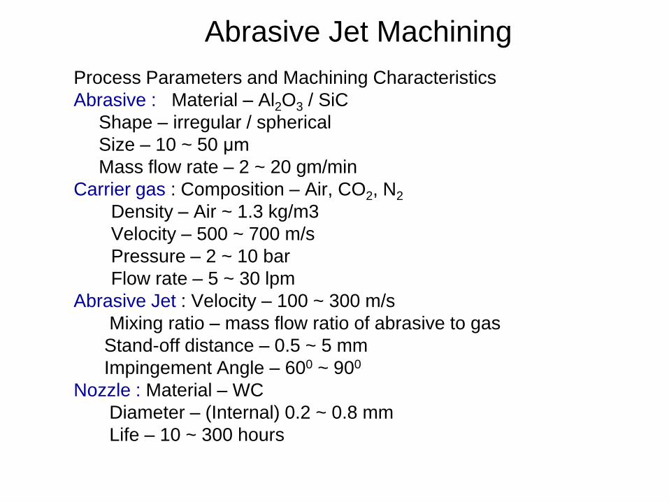
Abrasive Jet Machining Process Parameters and Machining Characteristics
Abrasive : Material – Al2O3 / SiC
Shape – irregular / spherical
Size – 10 ~ 50 μm
Mass flow rate – 2 ~ 20 gm/min
Carrier gas : Composition – Air, CO2, N2
Density – Air ~ 1.3 kg/m3
Velocity – 500 ~ 700 m/s
Pressure – 2 ~ 10 bar
Flow rate – 5 ~ 30 lpm
Abrasive Jet : Velocity – 100 ~ 300 m/s
Mixing ratio – mass flow ratio of abrasive to gas
Stand-off distance – 0.5 ~ 5 mm
Impingement Angle – 600 ~ 900
Nozzle : Material – WC
Diameter – (Internal) 0.2 ~ 0.8 mm
Life – 10 ~ 300 hours
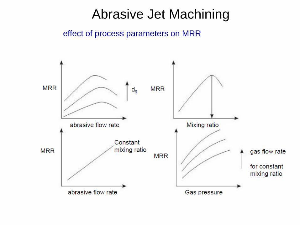
Abrasive Jet Machining
effect of process parameters on MRR

Abrasive Jet Machining
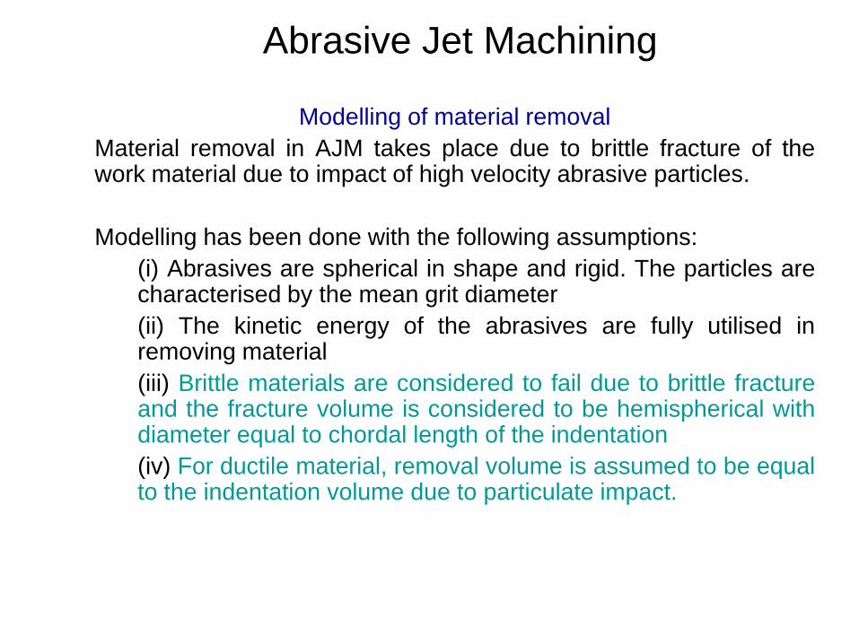
Abrasive Jet Machining
Modelling of material removal
Material removal in AJM takes place due to brittle fracture of the work material due to impact of high velocity abrasive particles.
Modelling has been done with the following assumptions:
(i) Abrasives are spherical in shape and rigid. The particles are characterised by the mean grit diameter
(ii) The kinetic energy of the abrasives are fully utilised in removing material
(iii) Brittle materials are considered to fail due to brittle fracture and the fracture volume is considered to be hemispherical with diameter equal to chordal length of the indentation
(iv) For ductile material, removal volume is assumed to be equal to the indentation volume due to particulate impact.


USM
• USM for machining brittle work material
• Material removal primarily occurs due to the indentation of the hard abrasive grits on the brittle work material.
• Other than this brittle failure of the work material due to indentation some material removal may occur due to free flowing impact of the abrasives against the work material and related solid-solid impact erosion,
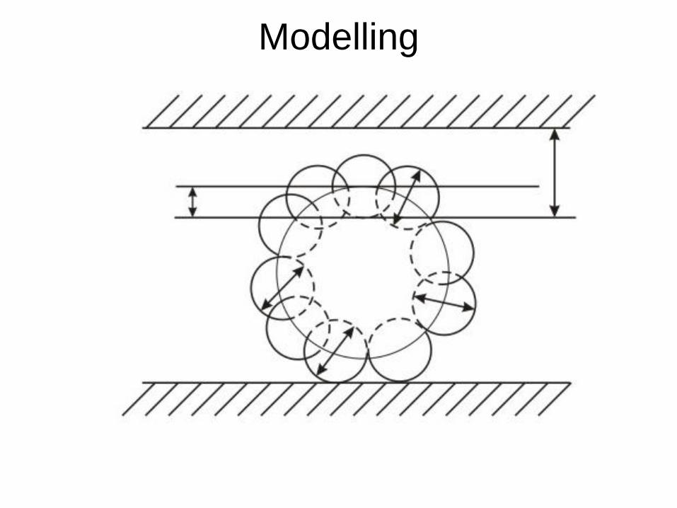
• Tool’s vibration – indentation by the abrasive grits.
• During indentation, due to Hertzian contact stresses, cracks would develop just below the contact site, then as indentation progresses the cracks would propagate due to increase in stress and ultimately lead to brittle fracture of the work material under each individual interaction site between the abrasive grits and the workpiece.
• The tool material should be such that indentation by the abrasive grits does not lead to brittle failure.
• Thus the tools are made of tough, strong and ductile materials like steel, stainless steel and other ductile metallic alloys.

USM • Process variables:
• Amplitude of vibration (ao) – 15 – 50 μm
• Frequency of vibration (f) – 19 – 25 kHz
• Feed force (F) – related to tool dimensions
• Feed pressure (p)
• Abrasive size – 15 μm – 150 μm
• Abrasive material – Al2O3
- SiC
- B4C
- Boronsilicarbide
- Diamond
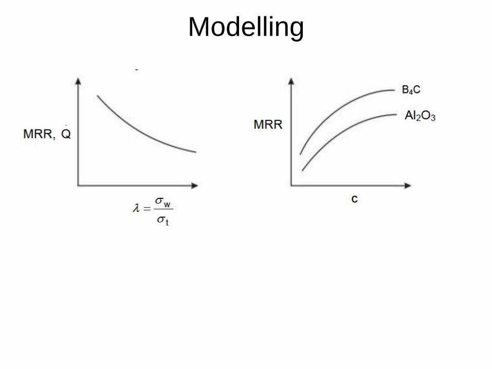
Flow strength of work material
Flow strength of the tool material
Contact area of the tool – A
Volume concentration of abrasive in water slurry – C
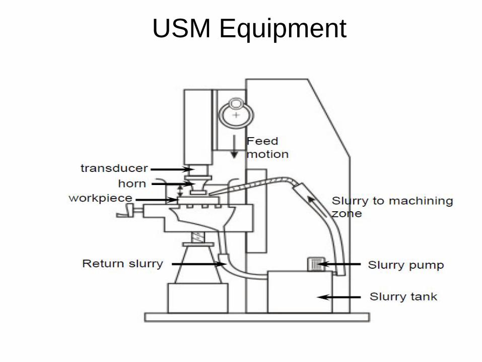
USM Equipment

Modelling

Modelling

Modelling

Modelling
Modelling

Water Jet and Abrasive Water Jet Machining

Water Jet and Abrasive Water Jet Machining
• WJM - Pure
• WJM - with stabilizer
• AWJM – entrained – three phase –
abrasive, water and air
• AWJM – suspended – two phase –
abrasive and water
o Direct pumping
o Indirect pumping
o Bypass pumping

General Experimental conditions
Orifice – Sapphires – 0.1 to 0.3 mm
Focussing Tube – WC – 0.8 to 2.4 mm
Pressure – 2500 to 4000 bar
Abrasive – garnet and olivine - #125 to #60
Abrasive flow - 0.1 to 1.0 Kg/min
Stand off distance – 1 to 2 mm
Machine Impact Angle – 60o to 900
Traverse Speed – 100 mm/min to 5 m/min
Depth of Cut – 1 mm to 250 mm

Water Jet and Abrasive Water Jet Machining
Water Jet and Abrasive Water Jet Machining
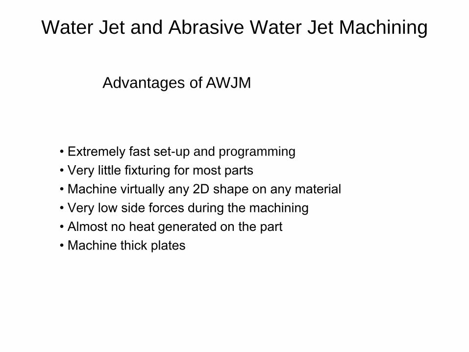
• Extremely fast set-up and programming
• Very little fixturing for most parts
• Machine virtually any 2D shape on any material
• Very low side forces during the machining
• Almost no heat generated on the part
• Machine thick plates
Advantages of AWJM

Components of AWJM
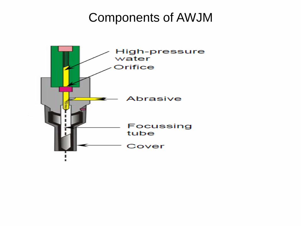
Components of AWJM

Components of AWJM

Components of AWJM
Catcher
(c) catcher plates (TiB2) (b) steel/WC/ceramic balls
(a) water basin
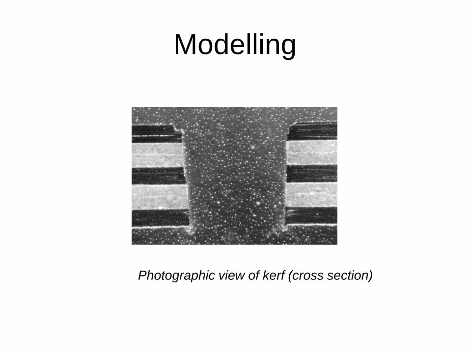
Modelling
Photographic view of kerf (cross section)