Non-reciprocal phase shift induced by an effective...
5
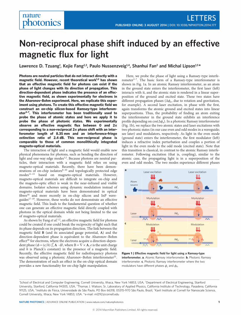
Non-reciprocal phase shift induced by an effective magnetic flux for light Lawrence D. Tzuang 1 , Kejie Fang 2,3 , Paulo Nussenzveig 1,4 , Shanhui Fan 2 and Michal Lipson 1,5 * Photons are neutral particles that do not interact directly with a magnetic field. However, recent theoretical work 1,2 has shown that an effective magnetic field for photons can exist if the phase of light changes with its direction of propagation. This direction-dependent phase indicates the presence of an effec- tive magnetic field, as shown experimentally for electrons in the Aharonov–Bohm experiment. Here, we replicate this exper- iment using photons. To create this effective magnetic field we construct an on-chip silicon-based Ramsey-type interferom- eter 3–7 . This interferometer has been traditionally used to probe the phase of atomic states and here we apply it to probe the phase of photonic states. We experimentally observe an effective magnetic flux between 0 and 2π corresponding to a non-reciprocal 2π phase shift with an inter- ferometer length of 8.35 mm and an interference-fringe extinction ratio of 2.4 dB. This non-reciprocal phase is comparable to those of common monolithically integrated magneto-optical materials. The interaction of light and a magnetic field would enable new physical phenomena for photons, such as bending the direction of light and one-way edge modes 1,2 . Because photons are neutral par- ticles, their interaction with a magnetic field relies on using magneto-optical materials. Recently, there have been demon- strations of on-chip isolators 8–10 and topologically protected edge modes 11–15 based on magneto-optical materials. However, magneto-optical materials are difficult to integrate on-chip and the magneto-optic effect is weak in the near-infrared and visible domains. Isolator schemes using dynamic modulation instead of magneto-optical materials have been demonstrated in optical fibres 16 and more recently in on-chip silicon and InP wave- guides 17–19 . However, these works do not demonstrate an effective magnetic field. This leads to the fundamental question of whether one can generate an effective magnetic field directly coupled with photons in the optical domain while not being limited to the use of magneto-optical materials. As shown by Fang et al. 1,2 , an effective magnetic field for photons could be created if one could break the reciprocity of light such that its phase depends on its propagation direction. The link between the magnetic field B (and its associated gauge potential, A) and the direction-dependent phase is equivalent to the Aharonov–Bohm effect 20 for electrons, where the electrons acquire a direction-depen- dent phase (f = (e/h) ∫ r ′ r A · dˆ r, where B = ∇ × A, e is the unit charge and h is Planck’s constant) in the presence of a magnetic field. Recently, the effective magnetic field for radiofrequency photons was observed using a photonic Aharonov–Bohm interferometer 21 . The demonstration of such an effect in the on-chip optical domain provides a new functionality for on-chip light manipulation. Here, we probe the phase of light using a Ramsey-type interfe- rometer 3–7 . The basic form of a Ramsey-type interferometer is shown in Fig. 1a. In an atomic Ramsey interferometer, as an atom in the ground state enters the interferometer, the first laser (left) interacts with it, and the atomic state is rendered in a linear super- position of the ground and excited state. These two states have different propagation phases (Δϕ a , due to rotation and gravitation, for example). A second laser excitation, in phase with the first, again transforms the atomic ground and excited states into linear superpositions. Thus, the probability of finding an atom exiting the interferometer in the ground state exhibits an interference profile depending on cos(Δϕ a ). In a photonic Ramsey interferometer (Fig. 1b), we replace the two atomic states and laser excitations with two photonic states (in our case even and odd modes in a waveguide; see later) and modulators, respectively. As light in the even mode (ground state) enters the interferometer, the first modulator (left) induces a refractive index perturbation and couples a portion of light in the even mode to the odd mode (excited state). Note that this transition is classical, in contrast to the atomic Ramsey interfe- rometer. Following excitation (that is, coupling), similar to the atomic case, the propagating light is in a superposition of the even and odd modes. The two modes experience different phases Laser Las ser Modulation a b Modulation Atom source b Ato sou Modulation Mdl i om urce Modulation Mdl i Laser excitation Laser excitation Δϕ a Δϕ p Laser Las ser Modulation c Modulation ϕ L ϕ L ϕ R ϕ R Δϕ p Figure 1 | Effective magnetic field for light using a Ramsey-type interferometer. a, Atomic Ramsey interferometer. b, Photonic Ramsey interferometer. c, Photonic Ramsey interferometer where the two modulators have different phases ϕ L and ϕ R . 1 School of Electrical and Computer Engineering, Cornell University, Ithaca, New York 14853, USA, 2 Department of Electrical Engineering, Stanford University, Stanford, California 94305, USA, 3 Thomas J. Watson, Sr, Laboratory of Applied Physics, California Institute of Technology, Pasadena, California 91125, USA, 4 Instituto de Física, Universidade de São Paulo, PO Box 66318, 05315-970 São Paulo, Brazil, 5 Kavli Institute at Cornell for Nanoscale Science, Cornell University, Ithaca, New York 14853, USA. *e-mail: [email protected] LETTERS PUBLISHED ONLINE: 3 AUGUST 2014 | DOI: 10.1038/NPHOTON.2014.177 NATURE PHOTONICS | ADVANCE ONLINE PUBLICATION | www.nature.com/naturephotonics 1 © 2014 Macmillan Publishers Limited. All rights reserved.
Transcript of Non-reciprocal phase shift induced by an effective...
Non-reciprocal phase shift induced by an effectivemagnetic flux for lightLawrence D. Tzuang1, Kejie Fang2,3, Paulo Nussenzveig1,4, Shanhui Fan2 and Michal Lipson1,5*
Photons are neutral particles that do not interact directly with amagnetic field. However, recent theoretical work1,2 has shownthat an effective magnetic field for photons can exist if thephase of light changes with its direction of propagation. Thisdirection-dependent phase indicates the presence of an effec-tive magnetic field, as shown experimentally for electrons inthe Aharonov–Bohm experiment. Here, we replicate this exper-iment using photons. To create this effective magnetic field weconstruct an on-chip silicon-based Ramsey-type interferom-eter3–7. This interferometer has been traditionally used toprobe the phase of atomic states and here we apply it toprobe the phase of photonic states. We experimentallyobserve an effective magnetic flux between 0 and 2πcorresponding to a non-reciprocal 2π phase shift with an inter-ferometer length of 8.35 mm and an interference-fringeextinction ratio of 2.4 dB. This non-reciprocal phase iscomparable to those of common monolithically integratedmagneto-optical materials.
The interaction of light and a magnetic field would enable newphysical phenomena for photons, such as bending the direction oflight and one-way edge modes1,2. Because photons are neutral par-ticles, their interaction with a magnetic field relies on usingmagneto-optical materials. Recently, there have been demon-strations of on-chip isolators8–10 and topologically protected edgemodes11–15 based on magneto-optical materials. However,magneto-optical materials are difficult to integrate on-chip andthe magneto-optic effect is weak in the near-infrared and visibledomains. Isolator schemes using dynamic modulation instead ofmagneto-optical materials have been demonstrated in opticalfibres16 and more recently in on-chip silicon and InP wave-guides17–19. However, these works do not demonstrate an effectivemagnetic field. This leads to the fundamental question of whetherone can generate an effective magnetic field directly coupled withphotons in the optical domain while not being limited to the useof magneto-optical materials.
As shown by Fang et al.1,2, an effective magnetic field for photonscould be created if one could break the reciprocity of light such thatits phase depends on its propagation direction. The link between themagnetic field B (and its associated gauge potential, A) and thedirection-dependent phase is equivalent to the Aharonov–Bohmeffect20 for electrons, where the electrons acquire a direction-depen-dent phase (f = (e/h) ∫r′r A · dr̂, where B = ∇ × A, e is the unit chargeand h is Planck’s constant) in the presence of a magnetic field.Recently, the effective magnetic field for radiofrequency photonswas observed using a photonic Aharonov–Bohm interferometer21.The demonstration of such an effect in the on-chip optical domainprovides a new functionality for on-chip light manipulation.
Here, we probe the phase of light using a Ramsey-type interfe-rometer3–7. The basic form of a Ramsey-type interferometer isshown in Fig. 1a. In an atomic Ramsey interferometer, as an atomin the ground state enters the interferometer, the first laser (left)interacts with it, and the atomic state is rendered in a linear super-position of the ground and excited state. These two states havedifferent propagation phases (Δϕa, due to rotation and gravitation,for example). A second laser excitation, in phase with the first,again transforms the atomic ground and excited states into linearsuperpositions. Thus, the probability of finding an atom exitingthe interferometer in the ground state exhibits an interferenceprofile depending on cos(Δϕa). In a photonic Ramsey interferometer(Fig. 1b), we replace the two atomic states and laser excitations withtwo photonic states (in our case even and odd modes in a waveguide;see later) and modulators, respectively. As light in the even mode(ground state) enters the interferometer, the first modulator (left)induces a refractive index perturbation and couples a portion oflight in the even mode to the odd mode (excited state). Note thatthis transition is classical, in contrast to the atomic Ramsey interfe-rometer. Following excitation (that is, coupling), similar to theatomic case, the propagating light is in a superposition of theeven and odd modes. The two modes experience different phases
LaserLasser
Modulation
a
b Modulation
Atom source
b
Atosou
ModulationM d l i
omurce
ModulationM d l i
Laser excitationLaser excitation
Δϕa
Δϕp
LaserLasser
Modulationc Modulation
ϕL ϕL ϕR ϕRΔϕp
Figure 1 | Effective magnetic field for light using a Ramsey-typeinterferometer. a, Atomic Ramsey interferometer. b, Photonic Ramseyinterferometer. c, Photonic Ramsey interferometer where the twomodulators have different phases ϕL and ϕR.
1School of Electrical and Computer Engineering, Cornell University, Ithaca, New York 14853, USA, 2Department of Electrical Engineering, StanfordUniversity, Stanford, California 94305, USA, 3Thomas J. Watson, Sr, Laboratory of Applied Physics, California Institute of Technology, Pasadena, California91125, USA, 4Instituto de Física, Universidade de São Paulo, PO Box 66318, 05315-970 São Paulo, Brazil, 5Kavli Institute at Cornell for Nanoscale Science,Cornell University, Ithaca, New York 14853, USA. *e-mail: [email protected]
LETTERSPUBLISHED ONLINE: 3 AUGUST 2014 | DOI: 10.1038/NPHOTON.2014.177
NATURE PHOTONICS | ADVANCE ONLINE PUBLICATION | www.nature.com/naturephotonics 1
© 2014 Macmillan Publishers Limited. All rights reserved.

(Δϕp) because of their different propagation constants. A secondmodulator (right) couples light in the odd mode back into the evenmode, and light exiting the interferometer exhibits an interferenceprofile, as in the atomic version but now depending on cos(Δϕp).
We use the Ramsey-type interferometer to probe the phase andbreak the reciprocity of light, thus inducing an effective magneticfield. This is achieved if the two modulators have different phasesϕL and ϕR (Fig. 1c). When inducing couplings, modulators imparttheir phases on photons. With respect to the phase of the local oscil-lator that drives the modulator, the imparted phase on photons isnegative (positive) if excitation (de-excitation) occurs1. If thephases of both modulators are identical (Fig. 1b), then the totalimparted phases are cancelled. However, if the modulators havedifferent phases (Fig. 1c), these imparted phases are detected andthe transmission becomes direction dependent. When light entersthe interferometer from the left (right), the output of the interfe-rometer is proportional to cos(Δϕp − ϕL + ϕR) (cos(Δϕp − ϕR + ϕL)).The non-reciprocal transmission is a result of an effective magneticflux, where Bflux = ϕL − ϕR (ref. 1). We implement the photonicRamsey-type interferometer by using the supermodes (even andodd modes) of a silicon coupled-waveguides structure. The modeprofiles are shown in Fig. 2a,b and the dimensions of the structurein Fig. 2c. The modulators are formed by embedding pn and npdiodes in the waveguides (Fig. 2c). Figure 2d presents a top viewof the carrier distribution under an applied sinusoidal voltage(red). The width of the depletion region (grey) changes as thesignal is applied, which induces a change in the refractive index ofthe coupled waveguides22,23. The pn–np configuration18 ensuresthat, at any instant in time, only one side of the coupled waveguidesexperiences a depletion width change, which enables couplingbetween the supermodes. Figure 2e presents an overview of theinterferometer. The two modulators are identical and only theirmodulation phases are different (ϕR and ϕL). The length of eachmodulator is 3.9 mm, which in simulation provides an equal prob-ability (50%) of populating both the two supermodes. The gap of the
coupled waveguides varies along the interferometer. At the edgeswhere the modulators are located, this gap is 900 nm (to separatethe two supermodes in frequency by a few GHz in the opticalc-band; Supplementary Fig. 1). In the centre, the gap tapers (taperlength of 100 µm) down to 550 nm and remains at this for a distanceLf such that the two supermodes experience different effectiveindices Δneff , and the phase difference between the two supermodesbecomes Δk × Lf (Δk = 2πΔneff/λ and λ is the optical wavelength).Here, Lf varies from 175 µm to 350 µm for different fabricateddevices. We also place multimode interference devices at each endof the interferometer so that only the even mode enters and exitsthe interferometer. A microscope image and a simulated powerdistribution of the multimode interference are shown in Fig. 2e(bottom images).
We experimentally observed non-reciprocal fringe patterns, indi-cating the existence of an effective magnetic flux from 0 to 2π cor-responding to a non-reciprocal 2π phase shift of 8.35 mm (length ofour interferometer) and a fringe extinction ratio of 2.4 dB. Figure 3ashows the optical transmission of our devices when light is propa-gating from left to right (L→ R) and right to left (R→ L). Two syn-chronized sinusoidal radiofrequency signals are applied such that ϕLand ϕR are correlated. We chose λ = 1,570 nm to match the modu-lation frequency ( fM = 4 GHz) to the frequency difference betweenthe supermodes. As shown in Fig. 3a we see full periods of sinusoi-dal optical transmissions (fringe patterns) as Δϕ (= ϕL − ϕR) variesfrom 0 to 2π. The solid curves in Fig. 3a are the theory curve fits(Supplementary Section II), all of which match the experimentswell. For all values of Lf we observe clear non-reciprocaltransmission, where the Δϕ that corresponds to the maximumtransmission for R→ L (ΔϕR→L) is different from that for L→ R(ΔϕL→R). Figure 3b also shows a linear relationship between|ΔϕR→L − ΔϕL→R| and Lf. This result is expected, because ΔϕR→L
and ΔϕL→R are both proportional to the phase difference betweenthe two supermodes, which is also proportional to Lf. The exper-iments (circles) match the theory well (solid line), and the data all
500
Gap
p pn n 250
35
Units: nm
x
y
z
3 μm
Lf
a
b
e
c
Gap = 900 nm
ϕL ϕR
d
p+ p+
t
x
p
n
0
V
+N
0
−N
Figure 2 | Ramsey-type interferometer design and fabrication. a,b, Simulated mode profiles for both the even mode (a) and the odd mode (b), whichcoexist in a silicon coupled waveguide structure. c, Cross-sectional view of the coupled waveguides. A set of pn and np diodes is doped to modulate therefractive index. d, Top view of carrier density (N) distribution in the coupled waveguide along the x-axis (slab omitted). The width of the depletion region(grey) changes over time as a sinusoidal signal is applied to the diodes. The applied sinusoidal voltage V is shown in red. e, A photonic Ramseyinterferometer implemented as a silicon coupled-waveguide structure. Bottom: microscope image and simulated light transmission of a pair of multimodeinterference devices located at the outer ends of the interferometer.
LETTERS NATURE PHOTONICS DOI: 10.1038/NPHOTON.2014.177
NATURE PHOTONICS | ADVANCE ONLINE PUBLICATION | www.nature.com/naturephotonics2
© 2014 Macmillan Publishers Limited. All rights reserved.

lie within the theoretical window (grey) that accounts for ±5%process variation (related to slab thickness and the gap of thecoupled waveguides). Figure 3c shows the transmission extinctionratios for light propagating from left to right (L→ R) and right toleft (R→ L) with increased coupling between the even and odd
modes, achieved by increasing the applied radiofrequency power.As the power increases, the extinction ratio for Lf = 325 µm increasesfrom 0.6 dB to 2.4 dB, corresponding to the population in the oddmode increasing from 3% to 12%. From these measurements weestimate that the power necessary to achieve maximum extinction
0.4
0.6
0.8
1.0
0.4
0.6
0.8
1.0
0.4
0.6
0.8
1.0
0.85
0.90
0.95
1.00
0.85
0.90
0.95
1.00
0 45 90 135 180 225 270 315 3600.85
0.90
0.95
1.00
Lf = 350 μm
325 μm
200 μm
ba
c
Lf (μm)
Nor
mal
ized
tran
smis
sionN
orm
aliz
ed tr
ansm
issi
onN
orm
aliz
ed tr
ansm
issi
onN
orm
aliz
ed tr
ansm
issi
on
0 45 90 135 180 225 270 315 360
Podd = 3%
6%
12%
200 250 300 350−200
−300
−400
−500
−600
Δϕ (deg)Δϕ (deg)
L RR L
L RR L
|Δϕ R
L−Δϕ
L
R| (
deg)
Figure 3 | Effective magnetic field experiment. a, Examples of measured (circles, normalized to the maximum curve fitted value) and theoretically fitted(solid lines) optical transmission for light travelling from left to right (L→ R, blue) and right to left (R→ L, red) for devices with different Lf, as a function ofthe phase difference between the two signals applied to the modulators (Δϕ=ϕL −ϕR). Wavelength = 1,570 nm; applied radiofrequency power = 24 dBm.Error bars represent one standard deviation from the measurement mean resulting from optical alignment fluctuations. b, Measured (circles) and theoretical(solid) difference Δϕ when the transmission is maximum for L→ R (ΔϕL→R) and R→ L (ΔϕR→L) versus Lf. The grey region indicates the error of thetheoretical curve when a 5% process variation is introduced. c, Measured and theoretically fitted optical transmission for light travelling from left to right(blue) and right to left (red) for Lf = 350 µm with increased population in the odd mode Podd (shown as percentages) achieved by increasing the appliedradiofrequency power.
b
0 90 180 2700.9
1.0
1.1
1.2
1.3
Nor
mal
ized
tran
smis
sion
(a.u
.)
0.9
1.0
1.1
1.2
1.3
Nor
mal
ized
tran
smis
sion
(a.u
.)
1,560
1,565
1,570
1,575
1,560
1,565
1,570
1,575
360
0
200
400
600
Frin
ge p
hase
(deg
)
Wavelength (nm)
a
1,560 1,570 1,580
L R
ϕL R
ϕR L
R L
Δϕ (deg)
0 90 180 270 360
Δϕ (deg)
Figure 4 | Wavelength dependence of the interference effect for the photonic Ramsey-type interferometer. a, Measured (grey circles, normalized to themaximum curve fitted value) and theoretically fitted (solid lines) optical transmission of light travelling from left to right (L→ R) and from right to left (R→ L)versus Δϕ for different laser wavelengths (1,560, 1,565, 1,570 and 1,575 nm) with Lf = 350 µm. b, Theoretical (dashed lines) and measured (circles) phase ofthe fringes for L→ R and R→ L versus wavelength.
NATURE PHOTONICS DOI: 10.1038/NPHOTON.2014.177 LETTERS
NATURE PHOTONICS | ADVANCE ONLINE PUBLICATION | www.nature.com/naturephotonics 3
© 2014 Macmillan Publishers Limited. All rights reserved.

(that is, 50% population in the odd mode) is at least an order ofmagnitude larger than the theoretical value of 160 mW. This highpower requirement in our experiments is due to both the RCcutoff (because the RC bandwidth of our device is ∼2.5 GHz,smaller than the modulation frequency of 4 GHz) and the ineffi-ciency of our pn diodes (we estimate our pn diodes to have only∼28% the efficiency of our designed value; for details seeSupplementary Fig. 5). In principle, redesigning the dispersion ofthe coupled waveguides to operate at lower radiofrequencies, opti-mizing the diode profile24 and increasing the length of the modu-lator should further increase the extinction ratio.
To confirm that the non-reciprocal fringes result from theinterference between the supermodes, we measured the fringes atdifferent wavelengths for Lf = 350 µm, as shown in Fig. 4a. Thiswavelength dependence of the fringe extinction ratio is due to thedispersion of the two supermodes; the frequency differencebetween the supermodes perfectly matches fM at λ≈ 1,570 nmand not at other wavelengths. In Fig. 4a we also observe a slightshift of these fringe phases as λ changes. This is expected, becauseΔneff is also wavelength dependent. Figure 4b plots the theoretical(dashed line) and measured (circles) wavelength dependence ofΔϕL→R and ΔϕR→L from 1,560 nm to 1,575 nm. It is clear that theexperiments and theory agree well.
In summary, we have used a new photonic interferometerscheme to measure a non-reciprocal phase of light (0 to 2π) andto induce an effective magnetic field for light. This non-reciprocal2π phase shift in our interferometer with a length of 8.35 mm iscomparable to commonly used monolithically integratedmagneto-optical materials such as polycrystalline YIG and Ce:YIGfilms9. The scheme we use here also quantifies the population ofboth photonic states. The materials and fabrication processeswe use are fully CMOS compatible. The demonstration of aneffective magnetic field in conjunction with recent theoreticalpredictions will enable the development of novel photonicdevices, including isolators and topological insulators. We alsoexpect this work to stimulate the exploration of physics andapplications of effective gauge potentials and topologicalmanipulation for photons25–31, by demonstrating for the first timean effective gauge potential for photons that break reciprocity andtime-reversal symmetry.
MethodsDevice fabrication. The device was fabricated using a silicon-on-insulator wafer.maN-2403 photoresist was used to mask the waveguide pattern using electron-beamlithography (EBL), and the silicon was then etched to leave a 35 nm slab. Afterforming the waveguide, four individual EBL steps using polymethyl methacrylatephotoresist masks were used to implant boron (p/p+, 1 × 10²⁰/8 × 1017 cm−3) andphosphorus (n/n+, 1 × 10²⁰/8 × 1017 cm−3) to form the doping profile shown inFig. 2c. The dopants were then activated using a furnace and the rapid thermalanneal process. After dopant activation, the waveguides were clad with 950 nmplasma-enhanced chemical vapour deposited SiO2. EBL was used to write the maskfor the vias, followed by reactive-ion etching through the SiO2. After etching,80 nm MoSi2 and 1.6 µm aluminium were deposited to form the electrical contact.
Measurement and experimental set-up. The two signals applied to each of themodulators were provided by two signal generators with the same frequency(4 GHz) to match the frequency separation of the even and odd modes at awavelength of 1,570 nm. We chose 4 GHz as the operational frequency because bothsignal generators provide the maximum output at this frequency. The two signalgenerators, each set at 24 dBm, were synchronized to ensure a correlated phase, andfor both signals, 1% of the radiofrequency power was dropped through adirectional coupler into the oscilloscope. The correlated phases from the two signalgenerators were then monitored using the oscilloscope. For both signals, theremaining 99% of power was delivered to the corresponding high-speedradiofrequency probes that contact the device pads. For the optical set-up, light wascoupled from a tunable laser into the waveguide through a lensed fibre, and lighttransmission through the device was coupled out through another lensed fibre.The output light was then collected by a photodetector. Forward and backwardtransmissions were measured by interchanging the fibre connectors connecting thelaser and photodetector. An illustration of the testing set-up is provided inSupplementary Figs 3 and 6.
Received 3 April 2014; accepted 2 July 2014;published online 3 August 2014
References1. Fang, K., Yu, Z. & Fan, S. Photonic Aharonov–Bohm effect based on
dynamic modulation. Phys. Rev. Lett. 108, 153901 (2012).2. Fang, K., Yu, Z. & Fan, S. Realizing effective magnetic field for photons
by controlling the phase of dynamic modulation. Nature Photon. 6,782–787 (2012).
3. Ramsey, N. F. A new molecular beam resonance method. Phys. Rev. 76,996 (1949).
4. Ramsey, N. F. Molecular Beams (Oxford Univ. Press, 1963).5. Bordé, C. J. Atomic interferometry with internal state labelling. Phys. Lett. A
140, 10–12 (1989).6. Ramsey, N. F. Experiments with separated oscillatory fields and hydrogen
masers. Rev. Mod. Phys. 62, 541–552 (1990).7. Dubetsky, B. & Kasevich, M. A. Atom interferometer as a selective sensor of
rotation or gravity. Phys. Rev. A 74, 023615 (2006).8. Shoji, Y., Mizumoto, T., Yokoi, H., Hsieh, I-W. & Osgood, R. M. Jr Magneto-
optical isolator with silicon waveguides fabricated by direct bonding. Appl. Phys.Lett. 92, 071117 (2008).
9. Bi, L. et al. On-chip optical isolation in monolithically integrated non-reciprocaloptical resonators. Nature Photon. 5, 758–762 (2011).
10. Tien, M.-C., Mizumoto, T., Pintus, P., Kromer, H. & Bowers, J. E. Silicon ringisolators with bonded nonreciprocal magneto-optic garnets. Opt. Express 19,11740–11745 (2011).
11. Haldane, F. D. M. & Raghu, S. Possible realization of directional opticalwaveguides in photonic crystals with broken time-reversal symmetry. Phys. Rev.Lett. 100, 013904 (2008).
12. Wang, Z., Chong, Y. D., Joannopoulos, J. D. & Soljačić, M. Reflection-freeone-way edge modes in a gyromagnetic photonic crystal. Phys. Rev. Lett.100, 013905 (2008).
13. Raghu, S. & Haldane, F. D. M. Analogs of quantum-Hall-effect edge statesin photonic crystals. Phys. Rev. A 78, 033834 (2008).
14. Wang, Z., Chong, Y., Joannopoulos, J. D. & Soljačić, M. Observation ofunidirectional backscattering-immune topological electromagnetic states.Nature 461, 772–775 (2009).
15. Poo, Y., Wu, R., Lin, Z., Yang, Y. & Chan, C. T. Experimental realization ofself-guiding unidirectional electromagnetic edge states. Phys. Rev. Lett.106, 093903 (2011).
16. Hwang, I. K., Yun, S. H. & Kim, B. Y. All-fiber-optic nonreciprocal modulator.Opt. Lett. 22, 507–509 (1997).
17. Doerr, C. R., Dupuis, N. & Zhang, L. Optical isolator using two tandem phasemodulators. Opt. Lett. 36, 4293–4295 (2011).
18. Lira, H., Yu, Z., Fan, S. & Lipson, M. Electrically driven nonreciprocityinduced by interband photonic transition on a silicon chip. Phys. Rev. Lett.109, 033901 (2012).
19. Doerr, C. R., Chen, L. & Vermeulen, D. Silicon photonics broadbandmodulation-based isolator. Opt. Express 22, 4493–4498 (2014).
20. Aharonov, Y. & Bohm, D. Significance of electromagnetic potentials in thequantum theory. Phys. Rev. 115, 485–491 (1959).
21. Fang, K., Yu, Z. & Fan, S. Experimental demonstration of a photonic Aharonov–Bohm effect at radio frequencies. Phys. Rev. B 87, 060301(R) (2013).
22. Soref, R. & Bennett, B. R. Electrooptical effects in silicon. IEEE J. QuantumElectron. 23, 123–129 (1987).
23. Gardes, F. Y. et al. High-speed modulation of a compact silicon ring resonatorbased on a reverse-biased pn diode. Opt. Express 17, 21986–21991 (2009).
24. Spector, S. J. et al. Operation and optimization of silicon-diode-basedoptical modulators. IEEE J. Sel. Top. Quantum Electron. 16, 165–172 (2010).
25. Hafezi, M., Demler, E. A., Lukin, M. D. & Taylor, J. M. Robust optical delaylines with topological protection. Nature Phys. 7, 907–912 (2011).
26. Umucalilar, R. O. & Carusotto, I. Artificial gauge field for photons in coupledcavity arrays. Phys. Rev. A 84, 043804 (2011).
27. Rechtsman, M. C. et al. Photonic Floquet topological insulators. Nature496, 196–200 (2013).
28. Khanikaev, A. B. et al. Photonic topological insulators. Nature Mater.12, 233–239 (2013).
29. Liang, G. Q. & Chong, Y. D. Optical resonator analog of a two-dimensionaltopological insulator. Phys. Rev. Lett. 110, 203904 (2013).
30. Longhi, S. Effective magnetic fields for photons in waveguide and coupledresonator lattices. Opt. Lett. 38, 3570–3573 (2013).
31. Hafezi, M., Mittal, S., Fan, J., Migdall, A. & Taylor, J. M. Imaging topologicaledge states in silicon photonics. Nature Photon. 7, 1001–1005 (2013).
AcknowledgementsThis work was supported by the National Science Foundation (NSF) through CIAN ERC(grant no. EEC 0812072) and by NSF grant no. 1202265. This work was performed in partat the Cornell Nanoscale Facility, a member of the National Nanotechnology InfrastructureNetwork, which is supported by the NSF. P.N. acknowledges support from Fundação de
LETTERS NATURE PHOTONICS DOI: 10.1038/NPHOTON.2014.177
NATURE PHOTONICS | ADVANCE ONLINE PUBLICATION | www.nature.com/naturephotonics4
© 2014 Macmillan Publishers Limited. All rights reserved.

Amparo à Pesquisa do Estado de São Paulo (FAPESP grant no. 2011/12140-6). The authorsacknowledge support from the US Air Force (AFOSR; program FA9550-09-1-0704 on‘Robust and Complex on-chip Nanophotonics’ supervised by G. Pomrenke).
Author contributionsL.D.T. performed the experiment. L.D.T. and K.F. designed the experiment and analysedthe data. P.N., S.F. and M.L. supervised the project. L.D.T and M.L. prepared themanuscript. K.F., P.N. and S.F. edited the manuscript.
Additional informationSupplementary information is available in the online version of the paper. Reprints andpermissions information is available online at www.nature.com/reprints. Correspondence andrequests for materials should be addressed to M.L.
Competing financial interestsThe authors declare no competing financial interests.
NATURE PHOTONICS DOI: 10.1038/NPHOTON.2014.177 LETTERS
NATURE PHOTONICS | ADVANCE ONLINE PUBLICATION | www.nature.com/naturephotonics 5
© 2014 Macmillan Publishers Limited. All rights reserved.