NON-PROPORTIONAL SHRINKAGE COMPENSATION 2011 173-176.pdf · NON-PROPORTIONAL SHRINKAGE COMPENSATION...
4
- 173 - NON-PROPORTIONAL SHRINKAGE COMPENSATION D. Ćurić a , S. Lemeš b , N. Zaimović-Uzunović b a Foundry "Novi život", Zenica, Bosnia and Herzegovina b University of Zenica, Faculty of Mechanical Engineering, Zenica, Bosnia and Herzegovina Abstract Shrinkage and warpage is a leading fact in casting. It is common to compensate shrinkage by scaling the tool by a certain percentage. The transformed 3D CAD model of a final product is used for tool generation. The transformations of CAD model include 3D scaling or external surface offset. Both methods are proportional and uniform in all three axes, and they are already included in a vast variety of CAD software packages. The shrinkage and warpage process, however, is not necessarily uniform, and some portions of a product can have different shrinkage ratio. Therefore, it is necessary to introduce the new CAD transformation technique: non-proportional 3D scaling. This paper deals with estimation of 3D function that should be used to transform the 3D CAD model of a tool, in order to obtain the optimum result. The casting tool and sample castings are measured on a coordinate measuring machine, and these measurement results are used to estimate the shrinkage percentage needed for different parts of a CAD model. Keywords: shrinkage compensation, casting, CAD, non-proportional 3D scaling 1. Introduction Phase change, which occurs in casting, leads to unavoidable shrinkage or warpage of manufactured parts. It is common to compensate shrinkage by scaling the tool by a certain percentage. This scaling is usually proportional and constant in all 3 dimensions. This research tries to investigate if it is justifiable to perform the non-proportional scaling, according to experimental results, i.e. precise measuring of model used to prepare the tool for sand casting, and subsequent comparison with castings manufactured with this tool. Reference points are placed on rectangular sample product, in order to be able to identify the coordinates which can be used to calculate exact scaling ratio for each reference point. The measurements are preformed with 3D Coordinate measuring machine. 2. Literature review Schubel et al examined usage of exfoliated clays as a means to control resin shrinkage within styrene based unsaturated polyester resins via nanocomposite [1]. Their results suggest that the exfoliated clay systems reduce shrinkage. Manetsberger et al investigated inhomogeneous shrinkage in the selective laser sintering (SLS) process using polymer materials [2]. Inhomogeneous shrinkage occurs due to inhomogeneous temperature distribution in the powder bed of the SLS machine. They discussed possible theories for a physical model of thermal shrinkage. Merle and Vincent [3] showed that shrinkage compensation mechanism in sheet moulding compounds is governed by the morphology resulting from phase separation and microvoids formation. They quantified microvoid morphology by using fractal 2D and 3D geometry. They demonstrated correlation between the morphologies of the matrix with phase separation and those of the microvoids by simulation. Yang and Ke [4] experimentally investigated the effects of adding compression on the thermal- mechanical history and on the quality of moulded parts. An instrumented moulding machine with a compression mechanism was used. Moulds for rectangular plate and circular disk were equipped with a movable cavity wall and shut-off mechanism. They have found that the thermomechanical history of the melt under injection compression moulding follows a quadrilateral-shaped path over the p-v-T diagram. Cuvelliez [5] studied the effect of the packing parameters, gate geometry, and mould elasticity on the final dimensions of a moulded part. His results highlighted the importance of gate design and
Transcript of NON-PROPORTIONAL SHRINKAGE COMPENSATION 2011 173-176.pdf · NON-PROPORTIONAL SHRINKAGE COMPENSATION...
- 173 -
NON-PROPORTIONAL SHRINKAGE COMPENSATION
D. Ćurića, S. Lemešb, N. Zaimović-Uzunovićb
a Foundry "Novi život", Zenica, Bosnia and Herzegovina b University of Zenica, Faculty of Mechanical Engineering, Zenica, Bosnia and Herzegovina
Abstract
Shrinkage and warpage is a leading fact in casting. It is common to compensate shrinkage by scaling the tool by a
certain percentage. The transformed 3D CAD model of a final product is used for tool generation. The transformations of
CAD model include 3D scaling or external surface offset. Both methods are proportional and uniform in all three axes, and
they are already included in a vast variety of CAD software packages. The shrinkage and warpage process, however, is not
necessarily uniform, and some portions of a product can have different shrinkage ratio. Therefore, it is necessary to
introduce the new CAD transformation technique: non-proportional 3D scaling. This paper deals with estimation of 3D
function that should be used to transform the 3D CAD model of a tool, in order to obtain the optimum result. The casting
tool and sample castings are measured on a coordinate measuring machine, and these measurement results are used to
estimate the shrinkage percentage needed for different parts of a CAD model.
Keywords: shrinkage compensation, casting, CAD, non-proportional 3D scaling
1. Introduction
Phase change, which occurs in casting, leads to unavoidable shrinkage or warpage of manufactured parts. It is common to compensate shrinkage by scaling the tool by a certain percentage. This scaling is usually proportional and constant in all 3 dimensions. This research tries to investigate if it is justifiable to perform the non-proportional scaling, according to experimental results, i.e. precise measuring of model used to prepare the tool for sand casting, and subsequent comparison with castings manufactured with this tool. Reference points are placed on rectangular sample product, in order to be able to identify the coordinates which can be used to calculate exact scaling ratio for each reference point. The measurements are preformed with 3D Coordinate measuring machine.
2. Literature review
Schubel et al examined usage of exfoliated clays as a means to control resin shrinkage within styrene based unsaturated polyester resins via nanocomposite [1]. Their results suggest that the exfoliated clay systems reduce shrinkage.
Manetsberger et al investigated inhomogeneous shrinkage in the selective laser sintering (SLS)
process using polymer materials [2]. Inhomogeneous shrinkage occurs due to inhomogeneous temperature distribution in the powder bed of the SLS machine. They discussed possible theories for a physical model of thermal shrinkage.
Merle and Vincent [3] showed that shrinkage compensation mechanism in sheet moulding compounds is governed by the morphology resulting from phase separation and microvoids formation. They quantified microvoid morphology by using fractal 2D and 3D geometry. They demonstrated correlation between the morphologies of the matrix with phase separation and those of the microvoids by simulation.
Yang and Ke [4] experimentally investigated the effects of adding compression on the thermal-mechanical history and on the quality of moulded parts. An instrumented moulding machine with a compression mechanism was used. Moulds for rectangular plate and circular disk were equipped with a movable cavity wall and shut-off mechanism. They have found that the thermomechanical history of the melt under injection compression moulding follows a quadrilateral-shaped path over the p-v-T diagram.
Cuvelliez [5] studied the effect of the packing parameters, gate geometry, and mould elasticity on the final dimensions of a moulded part. His results highlighted the importance of gate design and
- 174 -
NON-PROPORTIONAL SHRINKAGE COMPENSATION D. Ćurić, S. Lemeš, N. Zaimović-Uzunović
processing parameters on the dimensional accuracy of the part and low internal stress level.
Harris et al investigated the differences between SLA prototypes and metal castings that occur due to different shrinkage rates in these materials [6]. They investigated the mechanisms in SL tooling that induce different part properties. They proposed different approaches to modifying the moulding process which would allow the production of parts whose key morphological characteristics are closer to metal moulds.
Chira and Rus [7] studied the influence of pressure onto mould shrinkage. They established mathematical relations between pressure and volumetric changes.
Non-linear and non-uniform shrinkage distribution was used by Dong et al [8]. They obtained a reasonably accurate determination of the die profile for the investment casting of turbine blades by FEM-based methodology. By considering the preciously control of the geometrical shape for turbine blades in the investment casting process, they studied the die-casting mould cavity optimization, analyzed the mechanism of casting deformation, and proposed a compensation method for die design.
The shrinkage compensation in tooling process is usually based on the linear scaling method, which can be further divided into: uniform scaling method, chord length scaling method, mean camber line scaling method and shrinkage centre scaling method [9].
Ito et al [10] and Ferreira and Mateus [11] carried out a method with different shrinkages given along directions, but shrinkage used did not consider the influence caused by the structure and constraint conditions of the casting.
3. Pattern measurement
To produce a sand casting, toolmaker must fabricate necessary patterns. The pattern can be made of wood, metal, plastic or a variety of other materials, it has the external shape of the cast part, which is enlarged by a shrinkage allowance to compensate for contraction of liquid metal during solidification and cooling to room temperature.
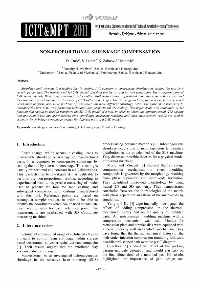
Fig. 1: 3D CAD model of a pattern.
The 3D CAD model of pattern used in this research is shown in Fig. 1. It consists of rectangular prismatic shape, which sides are tilted by draft angle. The reference points (Fig. 2) are marked with small cones. The gating system is included as a part of the pattern, and casting gate is realized as a cylindrical part, connected with prismatic pattern by means of trapezoidal gate.
Fig. 2: Layout of reference points on a pattern.
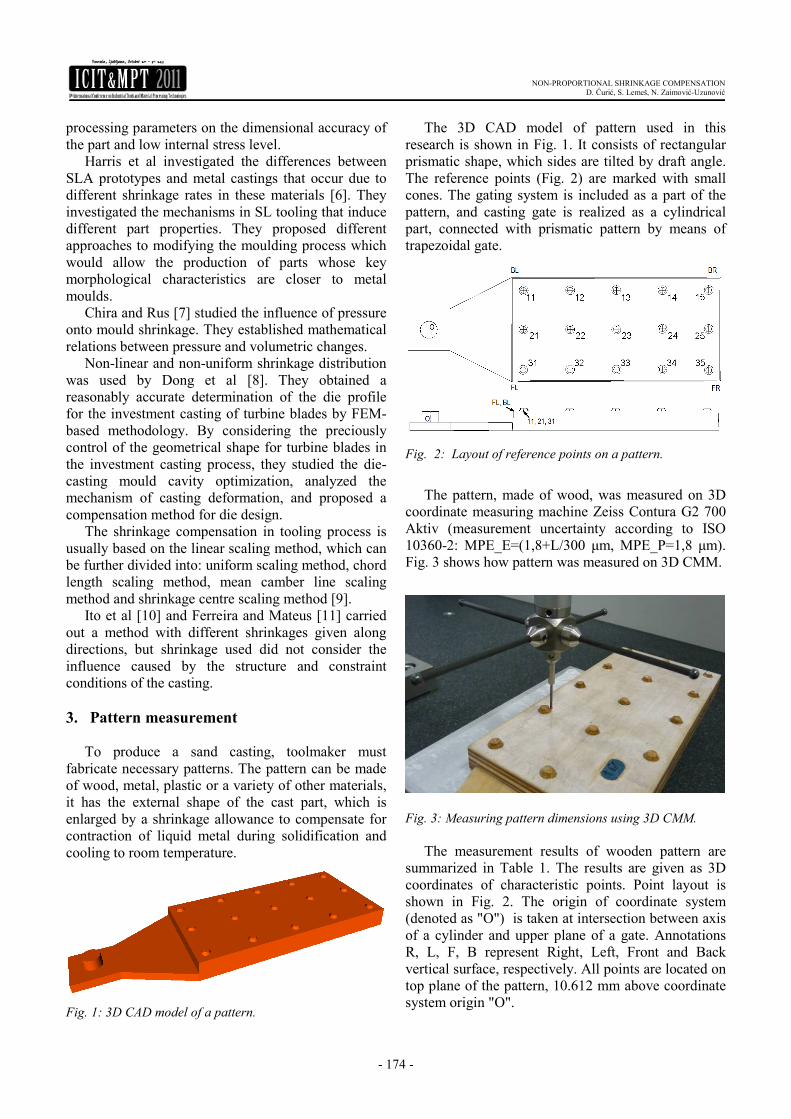
The pattern, made of wood, was measured on 3D
coordinate measuring machine Zeiss Contura G2 700 Aktiv (measurement uncertainty according to ISO 10360-2: MPE_E=(1,8+L/300 µm, MPE_P=1,8 µm). Fig. 3 shows how pattern was measured on 3D CMM.
Fig. 3: Measuring pattern dimensions using 3D CMM.
The measurement results of wooden pattern are
summarized in Table 1. The results are given as 3D coordinates of characteristic points. Point layout is shown in Fig. 2. The origin of coordinate system (denoted as "O") is taken at intersection between axis of a cylinder and upper plane of a gate. Annotations R, L, F, B represent Right, Left, Front and Back vertical surface, respectively. All points are located on top plane of the pattern, 10.612 mm above coordinate system origin "O".
- 175 -
NON-PROPORTIONAL SHRINKAGE COMPENSATION D. Ćurić, S. Lemeš, N. Zaimović-Uzunović
Table 1: Coordinates of reference points measured at
wooden pattern.
Point X Y Z Point 11 90,667 37,640 10,559 Point 12 135,068 37,961 10,559 Point 13 179,247 38,092 10,559 Point 14 223,527 38,028 10,558 Point 15 267,556 38,053 10,558 Point 21 90,536 0,417 10,559 Point 22 135,143 0,527 10,559 Point 23 179,040 0,221 10,559 Point 24 223,362 0,803 10,558 Point 25 267,401 0,628 10,558 Point 31 90,144 -38,269 10,559 Point 32 134,951 -38,082 10,559 Point 33 179,459 -38,208 10,559 Point 34 223,202 -37,946 10,559 Point 35 267,654 -38,513 10,558 Point BL 80,414 48,971 10,559 Point BR 278,281 49,358 10,558 Point FL 80,445 -48,710 10,559 Point FR 278,181 -48,128 10,558
4. Casting measurement
The pattern was then used to prepare sand moulds (Fig. 4) and sample parts were cast (Fig. 5). These parts are then measured using the same procedure as the one used in pattern measurement. The measurement results are summarized in Table 2.
Fig. 4: Moulds.
Fig. 5: Castings .
Table 2: Coordinates of reference points measured at
castings.
Point X Y Z Point 11 91,376 44,298 10,746 Point 12 135,273 44,725 10,562 Point 13 179,848 44,894 10,623 Point 14 223,819 45,397 10,775 Point 15 267,251 45,361 10,880 Point 21 91,344 7,003 10,615 Point 22 135,526 7,296 10,387 Point 23 179,544 7,016 10,455 Point 24 223,877 7,685 10,580 Point 25 266,729 7,618 10,765 Point 31 91,026 -31,583 10,486 Point 32 135,781 -31,371 10,423 Point 33 180,038 -31,448 10,602 Point 34 223,482 -30,945 10,630 Point 35 267,658 -31,462 10,752 Point BL 80,521 55,474 10,810 Point BR 278,850 56,283 10,970 Point FL 80,344 -42,157 10,963 Point FR 279,275 -41,394 10,763
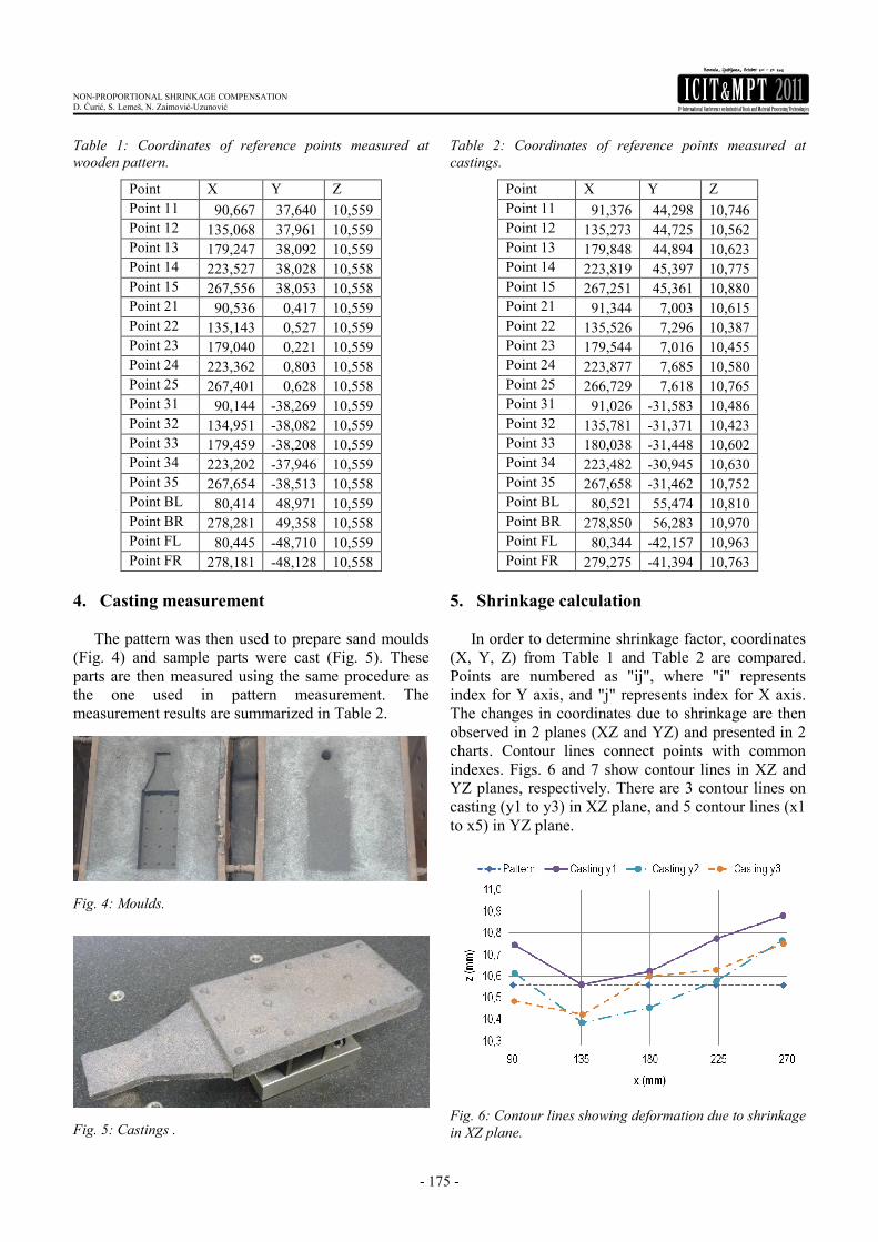
5. Shrinkage calculation
In order to determine shrinkage factor, coordinates (X, Y, Z) from Table 1 and Table 2 are compared. Points are numbered as "ij", where "i" represents index for Y axis, and "j" represents index for X axis. The changes in coordinates due to shrinkage are then observed in 2 planes (XZ and YZ) and presented in 2 charts. Contour lines connect points with common indexes. Figs. 6 and 7 show contour lines in XZ and YZ planes, respectively. There are 3 contour lines on casting (y1 to y3) in XZ plane, and 5 contour lines (x1 to x5) in YZ plane.
Fig. 6: Contour lines showing deformation due to shrinkage
in XZ plane.
- 176 -
NON-PROPORTIONAL SHRINKAGE COMPENSATION D. Ćurić, S. Lemeš, N. Zaimović-Uzunović
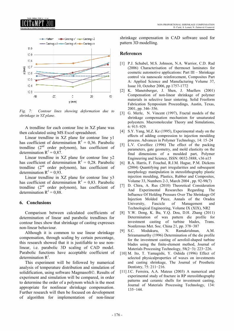
Fig. 7: Contour lines showing deformation due to
shrinkage in YZ plane.
A trendline for each contour line in XZ plane was
then calculated using MS Excel spreadsheet. Linear trendline in XZ plane for contour line y1
has coefficient of determination R2 = 0,36. Parabolic trendline (2nd order polynom), has coefficient of determination R2 = 0,87.
Linear trendline in XZ plane for contour line y2 has coefficient of determination R2 = 0,28. Parabolic trendline (2nd order polynom), has coefficient of determination R2 = 0,93.
Linear trendline in XZ plane for contour line y3 has coefficient of determination R2 = 0,83. Parabolic trendline (2nd order polynom), has coefficient of determination R2 = 0,88.
6. Conclusions
Comparison between calculated coefficients of determination of linear and parabolic trendlines for contour lines show that shrinkage of casting expresses non-linear behaviour.
Although it is common to use linear shrinkage compensation, through scaling by certain percentage, this research showed that it is justifiable to use non-linear, i.e. parabolic 3D scaling of CAD model. Parabolic functions have acceptable coefficient of determination R2.
This experiment will be followed by numerical analysis of temperature distribution and simulation of solidification, using software Magmasoft©. Results of experiment and simulation will be compared, in order to determine the order of a polynom which is the most appropriate for nonlinear shrinkage compensation. Further research will then be focused on development of algorithm for implementation of non-linear
shrinkage compensation in CAD software used for pattern 3D modelling.
References [1] P.J. Schubel, M.S. Johnson, N.A. Warrior, C.D. Rud
(2006) Characterisation of thermoset laminates for cosmetic automotive applications: Part III – Shrinkage control via nanoscale reinforcement, Composites Part A: Applied Science and Manufacturing Volume 37, Issue 10, October 2006, pp 1757-1772
[2] K. Manetsberger, J. Shen, J. Muellers (2001) Compensation of non-linear shrinkage of polymer materials in selective laser sintering. Solid Freeform Fabrication Symposium Proceedings, Austin, Texas, 2001, pp. 346–356.
[3] G. Merle, N. Vincent (1997), Fractal models of the shrinkage compensation mechanism for unsaturated polyesters. Macromolecular Theory and Simulations, 6: 915–929.
[4] S.Y. Yang, M.Z. Ke (1995), Experimental study on the effects of adding compression to injection moulding process. Advances in Polymer Technology, 14: 15–24
[5] L.V. Cuvelliez (1996) The effect of the packing parameters, gate geometry, and mold elasticity on the final dimensions of a moulded part, Polymer Engineering and Science, ISSN: 0032-3888, v36 n15
[6] R.A. Harris, F. Fouchal, R.J.M. Hague, P.M. Dickens (2004) Quantifying part irregularities and subsequent morphology manipulation in stereolithography plastic injection moulding, Plastics, Rubber and Composites, Volume 33, Numbers 2-3, March 2004 , pp. 92-98(7)
[7] D. Chira, A. Rus (2010) Theoretical Consideration And Experimental Researches Regarding The Influence Of Holding Pressure Over The Shrinkage Of Injection Molded Piece, Annals of the Oradea University, Fascicle of Management and Technological Engineering, Volume IX (XIX), NR2
[8] Y.W. Dong, K. Bu, Y.Q. Dou, D.H. Zhang (2011) Determination of wax pattern die profile for investment casting of turbine blades, Trans. Nonferrous Met. Soc. China 21, pp. 378−387
[9] S.C. Modukuru, N. Ramakrishnan, A.M. Sriramamurthy (1996) Determination of the die profile for the investment casting of aerofoil-shaped turbine blades using the finite-element method, Journal of Materials Processing Technology, 58(2−3): 223−226.
[10] M. Ito, T. Yamagishi, Y. Oshida (1996) Effect of selected physicalproperties of waxes on investments and casting shrinkage, The Journal of Prosthetic Dentistry, 75: 211−216.
[11] J.C. Ferreira, A.A. Mateus (2003) A numerical and experimental study of fracture in RP stereolithography patterns and ceramic shells for investment casting, Journal of Materials Processing Technology, 134: 135−144.