Non-Grey and Temperature Dependent Radiation Analysis Methods · · 2016-04-06Non-Grey and...
49
C&R TECHNOLOGIES C&R TECHNOLOGIES 303.971.0292 Fax 303.971.0035 www.crtech.com TFAWS 2005 Short Course Non-Grey and Temperature Dependent Radiation Analysis Methods Tim Panczak Additional Charts & Data Provided by Dan Green Ball Aerospace Corporation [email protected]
Transcript of Non-Grey and Temperature Dependent Radiation Analysis Methods · · 2016-04-06Non-Grey and...

C&R TECHNOLOGIES
C&R TECHNOLOGIES303.971.0292
Fax 303.971.0035www.crtech.com
TFAWS 2005 Short Course
Non-Grey and Temperature Dependent Radiation Analysis Methods
Tim Panczak
Additional Charts & Data Provided by
Dan GreenBall Aerospace Corporation

C&
R TE
CH
NO
LOG
IES
ww
w.crtech.com
Course Outline
Review of optical property definitionsemissivity, absorptivity, total, spectral, directional, hemispherical, intensity, power
Conditions for grey/non-grey radiation analysisConsider spectral distributions of emitted and incident radiation
Methods to implement non-grey analysisBanded approachSinda/FluintThermal Desktop/RadCAD/SindaWorks
Examples

C&
R TE
CH
NO
LOG
IES
ww
w.crtech.com
Spectral Distribution of Blackbody Emissive Power
• Planck’s Radiation Law:E(λ,T) = (2πhc2/λ5)/(ehc/λkT – 1)
• Flux (Qbb) = area under curve
• Qbb,T = σT4
σ = 5.6697 X 10⁻⁸
[W/m2-K4]
• Curves have similar shapes
λmax is proportional to 1/T
λmax
0.004 inches
Spec
t ral
Pow
er
DG

C&
R TE
CH
NO
LOG
IES
ww
w.crtech.com
Blackbody Spectral Power: Log Plot
• Everything shifts proportional to 1/T
• Max power occurs at longer wavelengths at lower temperatures
• Curve for a lower temperature is less than curve for a higher temperature at all wavelengths
• At low temperatures, power spreads over a wider range of wavelengths
λmaxT = 2897µ-KλT = 1148µ-K λT = 22917µ-K
98% of power
Spec
t ral
Pow
er
DG
C&
R TE
CH
NO
LOG
IES
ww
w.crtech.com
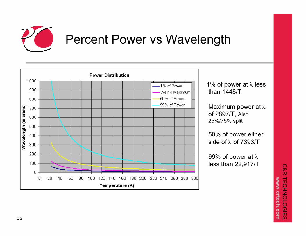
1% of power at λ less than 1448/T
Maximum power at λof 2897/T, Also 25%/75% split
50% of power either side of λ of 7393/T
99% of power at λless than 22,917/T
Percent Power vs Wavelength
DG

C&
R TE
CH
NO
LOG
IES
ww
w.crtech.com
Characterization of Real Surface Behavior
Materials are characterized by comparing their behavior with respect to the ideal black body
Nothing can emit more than a black bodyGiven by Planck’s Radiation LawEqual intensity in all directionsIntensity is Watts per projected area, per solid angle, per wavelength interval
Nothing can absorb more than a black bodyA blackbody absorbs all incident radiation

C&
R TE
CH
NO
LOG
IES
ww
w.crtech.com
Directional Spectral Emissivity
Dependent on wavelength, direction, and surface temperature
Power vs IntensitySubscripts: lambda, bThermal Radiation Heat Transfer 4th Edition, Siegel and Howell
)()()
sincos)( sincos)()
emitterb
emitteremitter
emitterb
emitteremitter
ΤiΤiΤ
ddddAΤiddddAΤiΤ
,,,,
= ,,,(
, ,,,
= ,,,(
λϕθλϕθλε
λϕθθθλλϕθθθϕθλϕθλε
λ
λλ
λ
λλ
C&
R TE
CH
NO
LOG
IES
ww
w.crtech.com
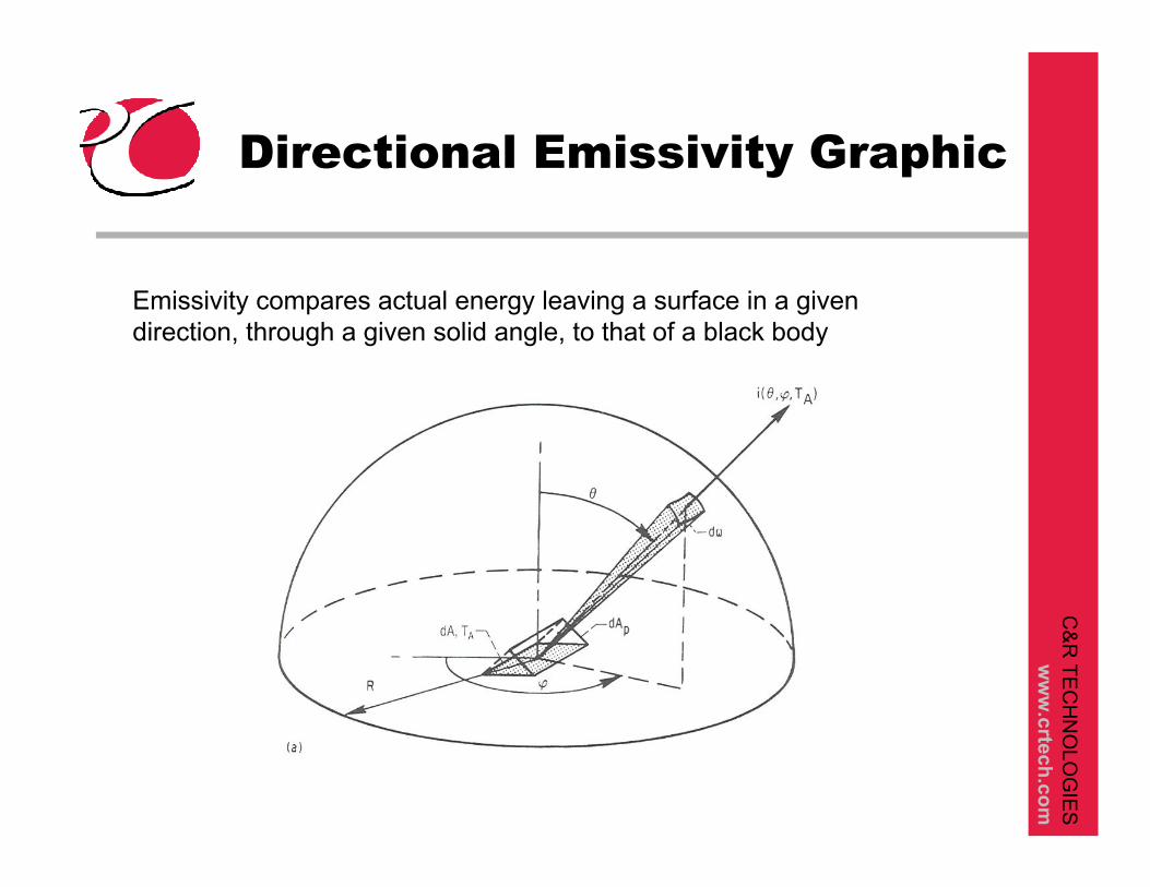
Directional Emissivity Graphic
Emissivity compares actual energy leaving a surface in a given direction, through a given solid angle, to that of a black body

C&
R TE
CH
NO
LOG
IES
ww
w.crtech.com
Power vs Intensity
Power is really a power flux:Spectral Hemispherical Emissive Power: [W/m2/mm]Total Hemispherical Emissive Power: [W/m2]
Directional Intensity is power per unit projected area, per solid angle:
Directional Spectral Intensity: [W/m2/ mm/ster]
When integrated over all directions:E = pI
C&
R TE
CH
NO
LOG
IES
ww
w.crtech.com
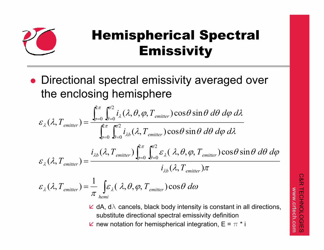
Hemispherical Spectral Emissivity
Directional spectral emissivity averaged over the enclosing hemisphere
dA, dl cancels, black body intensity is constant in all directions, substitute directional spectral emissivity definition new notation for hemispherical integration, E = p * i
∫
∫ ∫
∫ ∫∫ ∫
,,,( =,
,
,,,( ,=,
,
,,,=,
2
0=
/2
0=
2
0=
/2
0=
2
0=
/2
0=
hemiemitteremitter
emitterb
emitteremitterb
emitter
emitterb
emitter
emitter
dΤΤ
Τi
ddΤΤiΤ
dddΤi
dddΤiΤ
ωθϕθλεπ
λε
πλ
ϕθθθϕθλελλε
λϕθθθλ
λϕθθθϕθλλε
λλ
λ
π
ϕ
π
θ λλ
λ
π
ϕ
π
θ λ
π
ϕ
π
θ λ
λ
cos)1)(
)(
sincos))()(
sincos)(
sincos)()(

C&
R TE
CH
NO
LOG
IES
ww
w.crtech.com
Hemispherical Total Emissivity
Integrate hemispherical spectral emissivity over all wavelengths
40
0
0
0
0
)( ),)(
)(
cos))()(
sincos)(
sincos)()(
emitter
emitterbemitteremitter
emitterb
hemiemitteremitterb
emitter
emitterb
emitter
emitter
T
dΤiΤΤ
dΤi
ddΤΤiΤ
dddΤi
dddΤiΤ
σ
λλπλεε
λλπ
λωθϕθλελε
λϕθθθλ
λϕθθθϕθλε
λλ
λ
λλ
π
ϕ
π
θ λ
π
ϕ
π
θ λ
, ( =
,
,,,( ,=
,
,,,=
∫∫
∫ ∫
∫ ∫ ∫∫ ∫ ∫
∞
∞
∞
∞ 2
0=
/2
0=
∞ 2
0=
/2
0=

C&
R TE
CH
NO
LOG
IES
ww
w.crtech.com
Terminology
)( T,,, ϕθλε λ
Directional Spectral (basic fundamental definition):
)( T,,ϕθεDirectional Total (integrate over all wavelengths):
)( T,,ϕθεHemispherical Spectral (integrate over all directions):
)(TεHemispherical Total (integrate over all directions & wavelengths):
C&
R TE
CH
NO
LOG
IES
ww
w.crtech.com
Absorptivity
Defined as the fraction of energy incident on a body that is absorbed by the bodyIncident radiation depends on the source
Spectral distribution of the source is independent of the temperature of the absorber
More complex than emissivity, since directional and spectral characteristics of the source must be includedRelations exist between emissivity and absorptivity

C&
R TE
CH
NO
LOG
IES
ww
w.crtech.com
Directional Spectral Absorptivity
λωθϕθλλϕθλα
ϕθλα
λλ
λ
dddAiQddT
T
iabsorber
absorber
cos()(
incidentenergy absorbedenergy )(
,
2
),,=,,,
=,,,

C&
R TE
CH
NO
LOG
IES
ww
w.crtech.com
Equivalent view of Absorptivity
θωθθ cos coscos22 dAddARdA
RdAdA e
e ==
C&
R TE
CH
NO
LOG
IES
ww
w.crtech.com
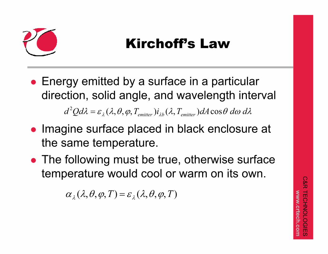
Energy emitted by a surface in a particular direction, solid angle, and wavelength interval
Imagine surface placed in black enclosure at the same temperature.The following must be true, otherwise surface temperature would cool or warm on its own.
Kirchoff’s Law
λωθλϕθλελ λλ dddATiTQdd emitterbemitter cos)()(2 ,,,,=
)()( TT ,,,=,,, ϕθλεϕθλα λλ
C&
R TE
CH
NO
LOG
IES
ww
w.crtech.com
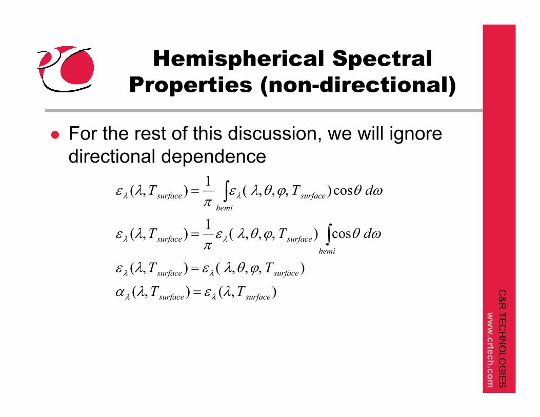
Hemispherical Spectral Properties (non-directional)
For the rest of this discussion, we will ignore directional dependence
)()(
))(
cos)1)(
cos)1)(
surfacesurface
surfacesurface
hemisurfacesurface
hemisurfacesurface
ΤΤ
ΤΤ
dΤΤ
dΤΤ
,=,
,,,( =,
,,,( =,
,,,( =,
∫
∫
λελα
ϕθλελε
ωθϕθλεπ
λε
ωθϕθλεπ
λε
λλ
λλ
λλ
λλ

C&
R TE
CH
NO
LOG
IES
ww
w.crtech.com
Total Emissivity Calculations
∆λ
300 K
180 K
25 K
ε(Τ) = [Σ(Εbb,λ,Τ)(ελ,Τ)(∆λ)] / Σ(Εbb,λ,Τ)(∆λ)
Temperature dependence has two aspects: Different spectral distribution of blackbody energy, and possible temperature dependent directional spectral emissivity/absorptivity
σT4
DG
Εbb
C&
R TE
CH
NO
LOG
IES
ww
w.crtech.com
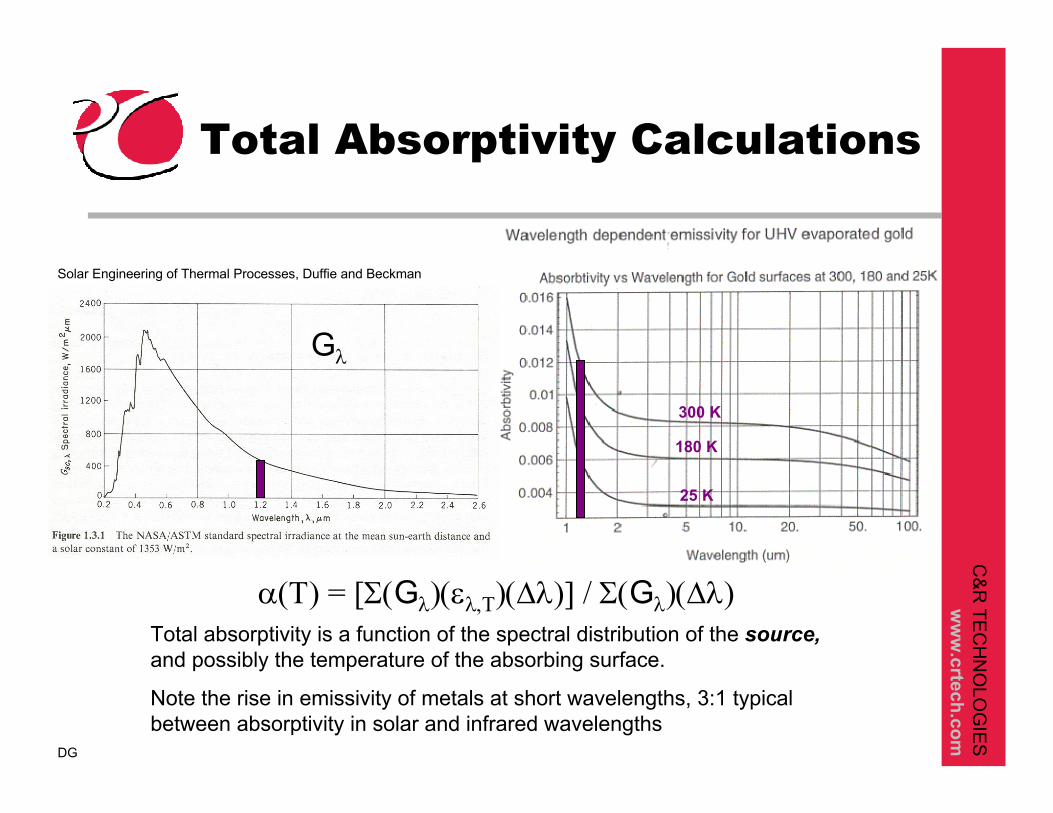
Total Absorptivity Calculations
300 K
180 K
25 K
Solar Engineering of Thermal Processes, Duffie and Beckman
α(Τ) = [Σ(Gλ)(ελ,Τ)(∆λ)] / Σ(Gλ)(∆λ)Total absorptivity is a function of the spectral distribution of the source,and possibly the temperature of the absorbing surface.
Note the rise in emissivity of metals at short wavelengths, 3:1 typical between absorptivity in solar and infrared wavelengths
DG
Gλ

C&
R TE
CH
NO
LOG
IES
ww
w.crtech.com
Radiation Exchange
1 2
42222121
)(1
41111212
)(2
4111121
41111
)) 12for Similarly,
)) 2by absorbedEnergy
) 2on incident Energy
) 1by emittedEnergy
2
1
TAΤFΤ
TAΤFΤ
TAΤF
TAΤ
spectrum
spectrum
σεα
σεα
σε
σε
((→
((
(
(
→
→
→
)) and ))or
)))):holdmust following The
) whereform,conductor radiation ,reciprocal typical,in the put this To
222)(
2111)(
1
221)(
1112)(
2
41
422121
12
21
ΤΤΤΤ
ΤΤΤΤ
TTKQ
spectrumspectrum
spectrumspectrum
(=((=(
((=((
−(= ↔↔
εαεα
εαεα
σ

C&
R TE
CH
NO
LOG
IES
ww
w.crtech.com
Reciprocity Conditions
Absorptivities evaluated using the spectral distribution of incoming radiationEmissivities evaluated using the blackbody radiationfrom itself.Reciprocity holds when emissivities for all surfaces are constant for all wavelengths that dominate the problem (surfaces are grey)
Find smallest wavelength from 98% power of hottest surface
Find longest wavelength from 1% power of coldest surface
200K to 350K would cover approximately 3 to 100 mm.

C&
R TE
CH
NO
LOG
IES
ww
w.crtech.com
Real Materials
Lets examine reciprocity and grey/non-grey conditions considering some real world materials
Non-conductors
Conductors
Intentional non-grey
C&
R TE
CH
NO
LOG
IES
ww
w.crtech.com
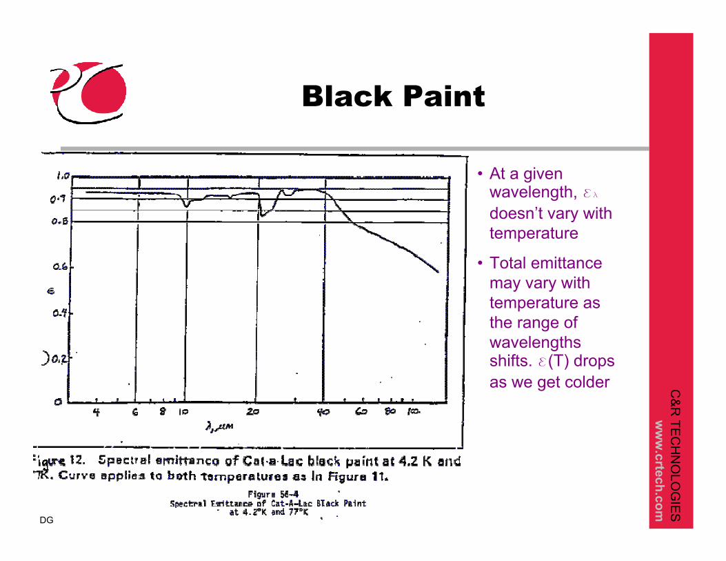
Black Paint
• At a given wavelength, el
doesn’t vary with temperature
• Total emittance may vary with temperature as the range of wavelengths shifts. e(T) drops as we get colder
DG
C&
R TE
CH
NO
LOG
IES
ww
w.crtech.com
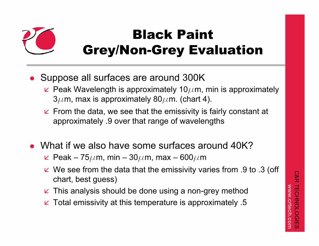
Black PaintGrey/Non-Grey Evaluation
Suppose all surfaces are around 300KPeak Wavelength is approximately 10mm, min is approximately 3mm, max is approximately 80mm. (chart 4).From the data, we see that the emissivity is fairly constant at approximately .9 over that range of wavelengths
What if we also have some surfaces around 40K?Peak – 75mm, min – 30mm, max – 600mmWe see from the data that the emissivity varies from .9 to .3 (off chart, best guess)This analysis should be done using a non-grey methodTotal emissivity at this temperature is approximately .5
C&
R TE
CH
NO
LOG
IES
ww
w.crtech.com
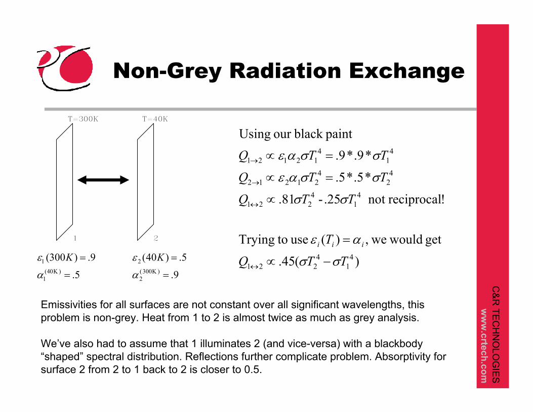
Non-Grey Radiation Exchange
1 2
5.
9.)300(
=
=)Κ(40
1
1
α
ε K
9.
5.)40(300
2
2
=
=)Κ(α
ε K
T=300K T=40K
)(45.
get would we,)( use toTrying
!reciprocalnot 25.- 81.
*5.*5.
*9.*9.paintblack our Using
41
4221
41
4221
42
421212
41
4121
TTQ
T
TTQ
TTQ
TTQ
iii
σσ
αε
σσ
σσαε
σσαε
−∝
=
∝
=∝
=∝
↔
↔
→
21→
Emissivities for all surfaces are not constant over all significant wavelengths, this problem is non-grey. Heat from 1 to 2 is almost twice as much as grey analysis.
We’ve also had to assume that 1 illuminates 2 (and vice-versa) with a blackbody “shaped” spectral distribution. Reflections further complicate problem. Absorptivity for surface 2 from 2 to 1 back to 2 is closer to 0.5.

C&
R TE
CH
NO
LOG
IES
ww
w.crtech.com
Temperature Dependent Emissivity
Total Hemispherical Emissivity varies with temperature for two reasons
As temperature changes, spectral distribution of blackbody energy changes. If emissivity vs wavelength is not uniform, total emissivity will change (previous example)Spectral emissivity, that is, the emissivity at a particular wavelength, may be a function of temperature
Both blackbody shift and wavelength dependence contribute to a total emissivity change with temperature
C&
R TE
CH
NO
LOG
IES
ww
w.crtech.com
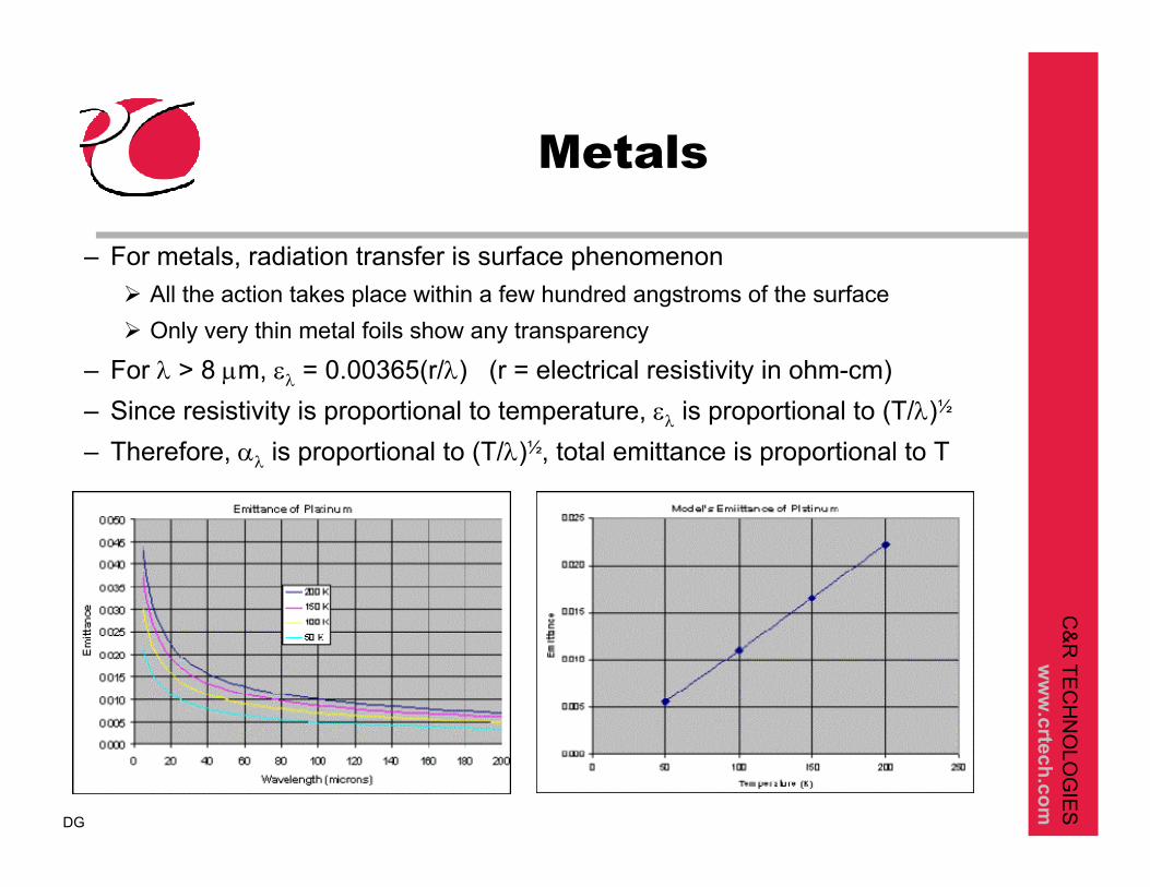
Metals
– For metals, radiation transfer is surface phenomenonAll the action takes place within a few hundred angstroms of the surfaceOnly very thin metal foils show any transparency
– For λ > 8 µm, ελ = 0.00365(r/λ) (r = electrical resistivity in ohm-cm)– Since resistivity is proportional to temperature, ελ is proportional to (T/λ)½
– Therefore, αλ is proportional to (T/λ)½, total emittance is proportional to T
DG

C&
R TE
CH
NO
LOG
IES
ww
w.crtech.com
More Metals
Emittance of metals varies proportionally to electrical resistance
Best conductors have lowest emittance
Pure metals have lowest electrical resistance
Alloys have higher emittances
Polished surfaces have loweremittance
Usually better than VDA
Annealing reduces electrical resistance
DG

C&
R TE
CH
NO
LOG
IES
ww
w.crtech.com
Temperature Dependent Emissivity and Reciprocity
In order to use reciprocal radiation conductors (radks), greyness must hold. That is, the emissivities of all materials must be constant over the significant range of wavelengths in the problemIf total emissivity is a strong function of T, then most likely your problem is not grey, and a traditional analysis will not work.Cases where temperature dependent total emissivitymay be valid:
Insignificant incident radiation (all goes to space, a’s out of the picture)Spectral Emissivity is a horizontal line, which just raises or lowers with temperature (still grey!)
C&
R TE
CH
NO
LOG
IES
ww
w.crtech.com
Intentional Non-Grey
So far, the focus has been on typical types of analysis where non-grey conditions may have been neglectedSome systems are intentionally non-grey
Thermal PhotovoltaicsContains a radiant heat source (600 C), a band gap filter, and a photovoltaic cell that operates in a narrow band
Annealing Processes for Silicon WafersOptical properties can also change as a function of time as the wafer grows

C&
R TE
CH
NO
LOG
IES
ww
w.crtech.com
Thermal Photovoltaics
Thermalphotovoltaic Spectral Control, DM DePoy et al., American Institute of Aeronautics and Astronautics
Definitely Non-Grey!Band gap is at the peak wavelength of the radiation source

C&
R TE
CH
NO
LOG
IES
ww
w.crtech.com
Non-Grey and Spectral Temperature Dependent
MethodsNon-grey problems are handled by breaking the problem up into wavelength bands, such that within each band, the problem becomes grey again.
Banded approach takes care of e(T) changesEven though total emissivity changes with temperature, if the material’s spectral distribution is not temperature dependent, no temperature dependent iteration is needed. Energy automatically shifts between the bands.
If there are temperature dependent spectral emissivities, they must be handled in an iterative matter
New radiation matrices (a matrix for each band) must be computed for new temperatures
C&
R TE
CH
NO
LOG
IES
ww
w.crtech.com
Banded Approach
With one band, we use the total emissivity and radiate using the total emissive power
We assume that the absorptivity = total emissivity (greyness holds within band)
With a banded approach, we break the problem up into separate wavelength bands
We also assume absorptivity = (band averaged) emissivityAbsorptivity will always tend towards emissivity as the bands become narrower
In each band, each node radiates with the amount of energy in that band, instead of
∞→→→→ 11 nλλλλλλ , ... , , ,0 322
4Tσ
4Tσ

C&
R TE
CH
NO
LOG
IES
ww
w.crtech.com
Banded Energy Balance
∑ =
∞−∞
++−
+−
+−=
−=
+
∞↔↔
↔↔
↔↔
↔↔↔
↔↔
1),,(
) ),,( ),,( (
... ) ),,( ),,( (
) ),,( ),,( (
) ),,0( ),,0( (band-multi
)(
band one
1
411
42221
41132
4223221
41121
4222121
4111
4221
02121
41
422121
32
21
1
TF
TTFTTFK
TTFTTFK
TTFTTFK
TTFTTFKQ
TTKQ
iiband
nbandnband
bandband
bandband
bandband
n
λλ
σλσλ
σλλσλλ
σλλσλλ
σλσλ
σσ
λ
λλ
λλ
λ

C&
R TE
CH
NO
LOG
IES
ww
w.crtech.com
Band Fraction Function
)()(),,(
)]()()()([1),,(
product theof in terms arranged-re
])()([1),,(
integrals twoas dimplemente
)(1
)(
)(),,(
tureat temperablackbody afor and between radiatedenergy offraction thegives ),,(
10202
0 50 52
0042
4
0
2
2
2
12
12
2
2
TFTFTF
TdTTETd
TTETF
T
dTEdTET
TF
dTETdTE
dTETF
TTF
band
T bT bband
bbband
b
b
b
band
band
λλλλ
λλλλσ
λλ
λ
λλλλσ
λλ
λλσλλ
λλλλ
λλλλ
λλ
λ λλ λ
λ
λ
λ
λ
λ
λ λ
λ
λ
λ λ
→→1
1
1
∞1
1
1
−=
,−
,=
,−,=
,=,
,=
∫∫
∫∫
∫∫∫
1
1

C&
R TE
CH
NO
LOG
IES
ww
w.crtech.com
Fractional Blackbody Emissive Power Function
available are solutions form series andar Both tabul
/2.998x10light of speed the/1.3806x10 constant Boltzmann
6.626x10 constant sPlanck'
/ ,
/1
2)(
80
23-
34-02
201
2
3
42
10
smcKJk
sJh
khcChcC
TC
deC
CTF T
==
==
==
==
=−
= ∫∞
→
λζ
ζζσπλ
ζ ζλ

C&
R TE
CH
NO
LOG
IES
ww
w.crtech.com
Non-Grey Implementation in Sinda/Fluint (Without TD)
Manually examine optical properties, pick wavelength bands, and generate emissivities for each bandPerform separate Radk calculations for each band, using the appropriate set of emissivitiesUse separate submodels and generate “band-radiation”nodes in each radk band (as sink or heater nodes)
For node MAIN.200 generate MAIN_B1.200, MAIN_B2.200, MAIN_B3.200, etc…
Set the temperature for each band-radiation node so that it matches the emissive power in the band
Perform a steady state or transient iterationTake the net heat flow into each band-radiation node and sum it into the parent node
42002002
41200 ),,( ΤTFΤ bandb σλλσ 1− =
C&
R TE
CH
NO
LOG
IES
ww
w.crtech.com
Implementation in Thermal Desktop/RadCAD
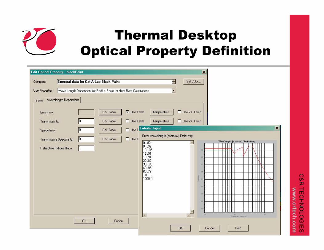
Non-grey and temperature varying spectral emissivity analysis automated using Thermal Desktop/RadCAD/SindaWorksDefine wavelength and/or temperature dependent properties using one form, under one optical property namePick bands for radk run using Case Set ManagerThat’s it!
RadCAD will recognize banded analysis and automatically compute required optical properties for each band, and automatically compute radks for each bandSindaWorks contains built-in logic to perform the band-fraction functions and appropriate energy bookkeepingDynamic link between SindaWorks and RadCAD if temperatures change such that new radks are required
C&
R TE
CH
NO
LOG
IES
ww
w.crtech.com
Thermal DesktopOptical Property Definition
C&
R TE
CH
NO
LOG
IES
ww
w.crtech.com
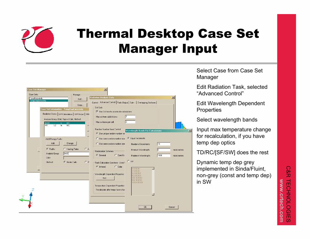
Thermal Desktop Case Set Manager Input
Select Case from Case Set Manager
Edit Radiation Task, selected “Advanced Control”
Edit Wavelength Dependent Properties
Select wavelength bands
Input max temperature change for recalculation, if you have temp dep optics
TD/RC/[SF/SW] does the rest
Dynamic temp dep grey implemented in Sinda/Fluint, non-grey (const and temp dep) in SW

C&
R TE
CH
NO
LOG
IES
ww
w.crtech.com
Examples
Demonstration

C&
R TE
CH
NO
LOG
IES
ww
w.crtech.com
Example 1Two Parallel Plates

C&
R TE
CH
NO
LOG
IES
ww
w.crtech.com
Problem DescriptionTwo Parallel Plates
1x1 rectangles separated by a distance of 16One rectangle held at 250 K.Spectral Emmisivity Data for Cat-A-Lac black paint used for analysis10,000,000 rays per surface
1st case: constant emissivity of .92 for both surfaces2nd case: constant emissivity of .92 for hot surface, constant emissivity of .5 for cold surface3rd case: wavelength dependent for both surfaces

C&
R TE
CH
NO
LOG
IES
ww
w.crtech.com
ResultsTwo Parallel Plates
Hot surface maintained at 250KCase 1, .92/.92: Cold surface 46.2 KCase 2, .92/.5 Cold surface 46.1 KCase 3, wave/wave Cold surface 50.8 K
Why the same results for the cold surface for both emissivity equal to .92 and .5 ?
Cold surface comes to equilibrium based on heat absorbed from the hot surface and radiation to space.Ratio remains essentially the same, at .92 it absorbs more heat from the hot surface, but also radiates more to space. At .5, itabsorbs less, but also radiates less.In reality, the cold surface absorbs at .92, but radiates at .5!
Modeled correctly only using a wavelength dependent analysis

C&
R TE
CH
NO
LOG
IES
ww
w.crtech.com
Example 2Simple Shields
C&
R TE
CH
NO
LOG
IES
ww
w.crtech.com
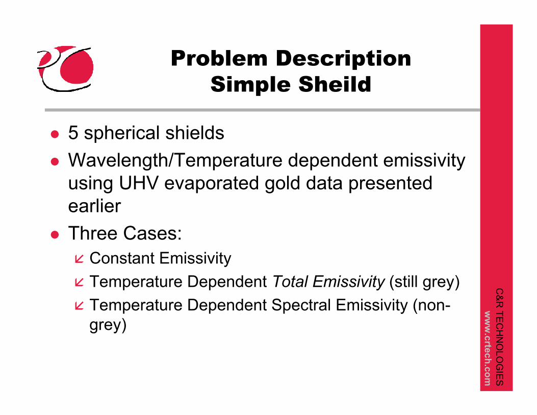
Problem DescriptionSimple Sheild
5 spherical shieldsWavelength/Temperature dependent emissivity using UHV evaporated gold data presented earlierThree Cases:
Constant EmissivityTemperature Dependent Total Emissivity (still grey)Temperature Dependent Spectral Emissivity (non-grey)

C&
R TE
CH
NO
LOG
IES
ww
w.crtech.com
Simple Shield Results
Min Temp Max Temp
Constant Emissivity 31.55 658.2
Temp dep Total Emissivity 31.77 658.8
Wavelength & Spectral Temp Dep 52.77 617.7
Temperature dependent Total Emissivity gives the same answers as constant emissivity, for the same reason as the two parallel plates.
Using total emissivity as a function of temperature is not a good approximation to a true non-grey analysis

C&
R TE
CH
NO
LOG
IES
ww
w.crtech.com
Summary
Examine optical properties and range of temperatures to determine if problem is non-greyUse banded approach to model the radiation exchange
Separate radk matrix for each bandRadk’s multiply the amount of energy emitted in the bandSum results of each band into nodal energy balance
Implemented and Automated in Thermal DesktopWavelength and temperature dependent optical property inputAutomatic breakdown and computation of bandsDynamic feature for temperature dependent radiation networks
Request for Test CasesIf you have an interesting application, please let me knowThanks!

C&
R TE
CH
NO
LOG
IES
ww
w.crtech.com
Q&A


![Thermal Imaging - cvip.louisville.edu · Only dependent on object’s temperature, no other characteristic [Tippler 2003]. Thermal radiation needs no transfer medium (i.e. thermal](https://static.fdocuments.net/doc/165x107/5ac547ec7f8b9ae06c8dae97/thermal-imaging-cvip-dependent-on-objects-temperature-no-other-characteristic.jpg)