
Non-Contact Safety Switch CES-I-AR-.-C04-… (Unicode ... · Operating Instructions Non-Contact...
36
EN Operating Instructions Non-Contact Safety Switch CES-I-AR-.-C04-… (Unicode/Multicode)
Transcript of Non-Contact Safety Switch CES-I-AR-.-C04-… (Unicode ... · Operating Instructions Non-Contact...

EN
Operating Instructions
Non-Contact Safety Switch
CES-I-AR-.-C04-… (Unicode/Multicode)

Operating InstructionsNon-Contact Safety Switch CES-I-AR-.-C04-…
2 (translation of the original operating instructions) 2119563-08-07/17
Contents
1. About this document ............................................................................................. 41.1. Scope ............................................................................................................................................4
1.2. Target group ..................................................................................................................................4
1.3. Key to symbols ...............................................................................................................................4
1.4. Supplementary documents ..............................................................................................................4
2. Correct use .......................................................................................................... 5
3. Description of the safety function .......................................................................... 6
4. Exclusion of liability and warranty ......................................................................... 6
5. General safety instructions.................................................................................... 6
6. Function ............................................................................................................... 76.1. Door monitoring output ...................................................................................................................7
6.2. Diagnostics output ..........................................................................................................................7
6.3. Limit-range monitoring ....................................................................................................................7
6.4. Switching states .............................................................................................................................7
7. ATEX .................................................................................................................... 87.1. Technical data of housing guard AM-C-C04-EX-137528 ......................................................................9
7.1.1. Dimension drawing of housing guard AM-C-C04-EX-137528 ...................................................97.2. Mounting ........................................................................................................................................9
8. Mounting ............................................................................................................ 10
9. Electrical connection .......................................................................................... 119.1. Notes about .........................................................................................................................12
9.2. Safety in case of faults ..................................................................................................................12
9.3. Fuse protection for power supply ...................................................................................................12
9.4. Requirements for connection cables ...............................................................................................13
9.5. Maximum cable lengths .................................................................................................................139.5.1. Determining cable lengths using the example table .............................................................14
9.6. Connector assignment of safety switch CES-I-AR .............................................................................15
9.7. Connector assignment of Y-distributor ............................................................................................16
9.8. Connection of a single AR device ...................................................................................................17
9.9. Connection of several devices in a switch chain ..............................................................................18
9.10. Information on operation on an AR evaluation unit ............................................................................20
9.11. Notes on operation with safe control systems .................................................................................20
32119563-08-07/17 (translation of the original operating instructions)
Operating InstructionsNon-Contact Safety Switch CES-I-AR-.-C04-…
EN
10. Setup ................................................................................................................. 2210.1. LED displays ................................................................................................................................22
10.2. Teach-in function for actuator (only for unicode evaluation) ...............................................................2210.2.1. Preparing device for the teach-in operation and teaching in actuator ....................................2210.2.2. Teach-in function with series connection, replacing and teaching in device ............................23
10.3. Functional check ...........................................................................................................................2310.3.1. Electrical function test ......................................................................................................23
11. System status table CES-I-AR-… .......................................................................... 24
12. Technical data .................................................................................................... 2512.1. Technical data of safety switch CES-I-AR-C04-… ..............................................................................25
12.1.1. Typical system times ........................................................................................................2612.1.2. Dimension drawing of safety switch CES-I-AR-C04-… ...........................................................27
12.2. Technical data of actuator CES-A-BBN-C04/CES-A-BBN-C04-EX-137527 ............................................2812.2.1. Dimension drawing ...........................................................................................................2812.2.2. Switching distances .........................................................................................................2812.2.3. Typical operating distance in approach direction A ..............................................................29
12.3. Technical data of actuator CES-A-BDN-06 ........................................................................................3012.3.1. Dimension drawing ...........................................................................................................3012.3.2. Switching distances .........................................................................................................30
13. Ordering information and accessories ................................................................. 31
14. Inspection and service ........................................................................................ 31
15. Service .............................................................................................................. 31
16. Declaration of conformity ................................................................................... 32

Operating InstructionsNon-Contact Safety Switch CES-I-AR-.-C04-…
4 (translation of the original operating instructions) 2119563-08-07/17
1. About this document1.1. ScopeThese operating instructions are valid for all CES-I-AR-.-C04-… These operating instructions, the document “Safety information and maintenance” and any enclosed data sheet form the complete user information for your device.
1.2. Target groupDesign engineers and installation planners for safety devices on machines, as well as setup and servicing staff possessing special expertise in handling safety components.
1.3. Key to symbolsSymbol/depiction Meaning
Printed document
Internet
www Document is available for download at www.euchner.com
Document on CD
DANGER WARNING CAUTION
Safety precautionsDanger of death or severe injuriesWarning about possible injuriesCaution Slight injuries possible
NOTICE Important!
Notice about possible device damageImportant information
Tip Useful information
1.4. Supplementary documentsThe overall documentation for this device consists of the following documents:
Document title(document number) Contents
Safety information and maintenance CES-AR(2091181)
Basic information for safe setup and service
Operating instructions(2119563) (this document)
Possibly enclosed data sheet Item-specific information about deviations or additions
Important!
Always read all documents to gain a complete overview of safe installation, setup and use of the device. The documents can be downloaded from www.euchner.com. For this purpose enter the doc. no. in the search box.

52119563-08-07/17 (translation of the original operating instructions)
Operating InstructionsNon-Contact Safety Switch CES-I-AR-.-C04-…
EN
2. Correct useSafety switches series CES-I-AR are interlocking devices without guard locking (type 4). The device meets the requirements according to EN IEC 60947-5-3. Devices with unicode evaluation possess a high coding level, devices with multicode eval-uation possess a low coding level.
In combination with a movable safety guard and the machine control, this safety component prevents dangerous machine functions from occurring while the safety guard is open. A stop command is triggered if the safety guard is opened during the dangerous machine function.
This means: Ì Starting commands that cause a dangerous machine function must become active only when the safety guard is closed. Ì Opening the safety guard triggers a stop command. Ì Closing a safety guard must not cause automatic starting of a dangerous machine function. A separate start command must be issued. For exceptions, refer to EN ISO 12100 or relevant C-standards.
Before the device is used, a risk assessment must be performed on the machine, e.g. in accordance with the following standards: Ì EN ISO 13849-1, Safety of machinery – Safety-related parts of control systems – Part 1: General principles for design Ì EN ISO 12100, Safety of machinery – General principles for design – Risk assessment and risk reduction Ì IEC 62061, Safety of machinery – Functional safety of safety-related electrical, electronic and programmable electronic control systems.
Correct use includes observing the relevant requirements for installation and operation, particularly based on the following standards: Ì EN ISO 13849-1, Safety of machinery – Safety-related parts of control systems – Part 1: General principles for design Ì EN ISO 14119 (supersedes EN 1088), Safety of machinery – Interlocking devices associated with guards – Principles for design and selection Ì EN 60204-1, Safety of machinery – Electrical equipment of machines.
The safety switch is only allowed to be operated in conjunction with the intended EUCHNER CES actuators and the related connection components from EUCHNER. On the use of different actuators or other connection components, EUCHNER provides no warranty for safe function.
Connection of several devices in an AR switch chain is permitted only using devices intended for series connection in an AR switch chain. Check this in the instructions of the device in question.
A maximum of 20 safety switches are allowed to be operated in a switch chain.
Important!
Ì The user is responsible for the proper integration of the device into a safe overall system. For this purpose, the overall system must be validated, e.g. in accordance with EN ISO 13849-2. Ì It is only allowed to use components that are permissible in accordance with the table below.
Table 1: Possible combinations for CES components
Safety switch
Actuator
CES-A-BBN-C04-115271 CES-A-BDN-06-104730
CES-I-AR-.-C04-...
Key to symbols Combination possible
NOTICE
The devices can be operated on an AR evaluation unit. Please refer to the operating instructions for the relevant AR evaluation unit for more information.
Operating InstructionsNon-Contact Safety Switch CES-I-AR-.-C04-…
6 (translation of the original operating instructions) 2119563-08-07/17
3. Description of the safety functionDevices from this series feature the following safety functions:
Monitoring of the safety guard position (interlocking device according to EN ISO 14119)
Ì Safety function: - The safety outputs are switched off when the safety guard is open (see chapter 6.4. Switching states on page 7).
Ì Safety characteristics: category, Performance Level, PFHD (see chapter 12. Technical data on page 25).
4. Exclusion of liability and warrantyIn case of failure to comply with the conditions for correct use stated above, or if the safety instructions are not followed, or if any servicing is not performed as required, liability will be excluded and the warranty void.
5. General safety instructionsSafety switches fulfill personal protection functions. Incorrect installation or tampering can lead to fatal injuries to personnel.
Check the safe function of the safety guard particularly Ì after any setup work Ì after the replacement of a system component Ì after an extended period without use Ì after every fault
Independent of these checks, the safe function of the safety guard should be checked at suitable intervals as part of the maintenance schedule.
WARNING
Danger to life due to improper installation or due to bypassing (tampering). Safety components fulfill a personal protection function. Ì Safety components must not be bypassed, turned away, removed or otherwise rendered ineffec-tive. On this topic pay attention in particular to the measures for reducing the possibility of bypass-ing according to EN ISO 14119:2013, section 7. Ì The switching operation must be triggered only by actuators designated for this purpose. Ì Prevent bypassing by means of replacement actuators (only for multicode evaluation). For this purpose, restrict access to actuators and to keys for releases, for example. Ì Mounting, electrical connection and setup only by authorized personnel possessing the following knowledge: - specialist knowledge in handling safety components - knowledge about the applicable EMC regulations - knowledge about the applicable regulations on occupational safety and accident prevention.
Important!
Prior to use, read the operating instructions and keep these in a safe place. Ensure the operating instructions are always available during mounting, setup and servicing. EUCHNER cannot provide any warranty in relation to the readability of the CD for the storage period required. For this reason you should archive a printed copy of the operating instructions. You can download the operating instruc-tions from www.euchner.com.

72119563-08-07/17 (translation of the original operating instructions)
Operating InstructionsNon-Contact Safety Switch CES-I-AR-.-C04-…
EN
6. FunctionThe safety switch monitors the position of movable safety guards. The safety outputs are switched on/off when the actuator is moved to/removed from the operating distance.
The system consists of the following components: coded actuator (transponder) and switch.
Whether the device learns the complete actuator code (unicode) or not (multicode) depends on the respective version. Ì Devices with unicode evaluation: The actuator must be assigned to the safety switch by a teach-in operation so that it is detected by the system. This unambiguous assignment ensures a particularly high level of protection against tam-pering. The system thus possesses a high coding level. Ì Devices with multicode evaluation: Unlike systems with unique code detection, on multicode devices a specific code is not requested but instead it is only checked whether the actuator is of a type that can be detected by the system (multicode detection). There is no exact comparison of the actuator code with the taught-in code in the safety switch (unique code detection). The system possesses a low coding level.
When the safety guard is closed, the actuator is moved towards the safety switch. When the switch-on distance is reached, power is supplied to the actuator by the switch and data is transferred.
If a permissible code is detected, the safety outputs are switched on.
The safety outputs are switched off when the safety guard is opened.
In the event of a fault in the safety switch, the safety outputs are switched off and the DIA LED illuminates red. The occurrence of faults is detected at the latest on the next demand to close the safety outputs (e.g. on starting).
6.1. Door monitoring outputThe door monitoring output is switched on as soon as a valid actuator is detected in the operating range.
6.2. Diagnostics outputThe diagnostics output is switched on in the event of a fault (switch-on condition as for DIA LED).
6.3. Limit-range monitoringIf the safety door with the actuator should settle over time, the actuator can drift out of the read head operating distance. The device recognizes this situation and indicates that the actuator is in the limit range by flashing the STATE LED. This allows the safety door to be readjusted in time. Also see chapter 11. System status table CES-I-AR-… on page 24.
6.4. Switching statesThe detailed switching states for your switch can be found in the system status table. All safety outputs, monitoring outputs and display LEDs are described there.
Safety guard closed(actuator in the operating distance and permissi-
ble code detected)
Safety guard open (actuator not in the operating distance)
Safety outputs FO1A and FO1B on off
Monitoring output OD on off

Operating InstructionsNon-Contact Safety Switch CES-I-AR-.-C04-…
8 (translation of the original operating instructions) 2119563-08-07/17
7. ATEXSafety switches from series CES-I-AR-.-C04-… can be used in potentially explosive atmospheres when equipped with housing guard AM-C-C04-EX-137528 available as an accessory.
Correct use includes observing the relevant requirements for installation and operation, particularly based on the following standards: Ì EN 1127-1, Explosive atmospheres – Explosion prevention and protection – Part 1: Basic concepts and methodology Ì EN 60079-0, Explosive atmospheres – Part 0: Equipment – General requirements Ì EN 60079-11, Explosive atmospheres – Part 11: Equipment protection by intrinsic safety “i” Ì EN 60079-14, Explosive atmospheres – Part 14: Electrical installations design, selection and erection Ì EN 60079-15, Explosive atmospheres - Part 15: Equipment protection by type of protection “n” Ì EN 60079-31, Explosive atmospheres – Part 31: Equipment dust ignition protection by enclosure “t”.
The safety switch is allowed to be operated only in conjunction with the intended actuator CES-A-BBN-C04-EX-137527 from EUCHNER and the related connection components from EUCHNER. On the use of different actuators or other connection components, EUCHNER provides no warranty for safe function.
Safety switches with ATEX identification marking from EUCHNER are not safety devices as defined by the ATEX Directive.
Important!
In order to achieve the explosion protection stated, all the conditions in the operating instructions must be met. HIGH RISK product.
Devices with ATEX rating may be operated only with actuators that also have an ATEX rating for the same zone.
ATEX rating
Housing guard AM-C-C04-EX-137528 in combination with safety switch CES-I-AR-.-C04-…
II3G Ex nA IIB T6 Gc X
II3D Ex tc IIIC T80°C Dc X
Actuator CES-A-BBN-C04-EX-137527
II3G Ex ic IIC T6 Gc
II3D Ex ic IIIC T85°C Dc X
X = It is essential to fit the housing guard as shock protection. All the electrical connections must either be isolated from the mains supply by a safety transformer according to IEC 61558-2-6 with limited output voltage in the event of a fault, or by other equivalent isolation measures (PELV).
Permanently and inseparably connect the actuator using the supplied non-removable screws.
To prevent electrostatic charging: Ì Do not subject the switch to any processes that generate a large amount of charge. Ì Clean only with a damp cloth!
Protection against mechanical effects on the switch: Ì Fit the switch on a flat surface. Install the switch so that the rear housing is entirely covered in order to protect it from mechanical damage through impact. Ì All connection cables and plug connectors must be laid such that they are protected against mechanical damage. Ì The connection cable must be laid rigidly; it is not permissible to lay the cable so that it can move (e.g. in a drag chain).
No tools (e.g. grinding or cutting devices) in accordance with DIN EN 1127-1, Annex A, point b) may be used.
If damage or wear is found, the complete switch including housing guard and actuator must be replaced. Replacement of individual parts or assemblies is not permitted.
92119563-08-07/17 (translation of the original operating instructions)
Operating InstructionsNon-Contact Safety Switch CES-I-AR-.-C04-…
EN
The supplied type label must be affixed on the safety switch.
On use in potentially explosive atmospheres, there is a danger of explosion due to electrical sparks. Ì Never connect or disconnect connector when live.
7.1. Technical data of housing guard AM-C-C04-EX-137528Parameter Value Unit
min. typ. max.
Housing material PBT/PC plastic
Dimensions 75 x 30 x 20 mm
Weight 0.02 kg
Ambient temperature - 25 - + 65 °C
Tightening torque of fixing screw in combination with CES-I-AR-.-C04-… - - 60 Ncm
7.1.1. Dimension drawing of housing guard AM-C-C04-EX-137528
F-F
2,8 7,
2 5
20
75
30
32
F
F
7.2. Mounting
1
2
1 Affix ATEX type label 2 Place safety switch into the housing guard depending on alignment

Operating InstructionsNon-Contact Safety Switch CES-I-AR-.-C04-…
10 (translation of the original operating instructions) 2119563-08-07/17
8. MountingCAUTION
Safety switches must not be bypassed (bridging of contacts), turned away, removed or otherwise rendered ineffective. Ì Observe EN ISO 14119:2013, section 7, for information about reducing the possibilities for by-passing an interlocking device.
NOTICE
Risk of damage to equipment and malfunctions as a result of incorrect installation. Ì Safety switches and actuators must not be used as an end stop. Ì Observe EN ISO 14119:2013, sections 5.2 and 5.3, for information about fastening the safety switch and the actuator. Ì From the assured switch-off distance Sar, the safety outputs are safely shut down. Ì When mounting several safety switches, observe the stipulated minimum distance to avoid mutual interference.
.
min. 140 mm
Ì The operating distance changes during the mounting of the actuator as a function of the material used for the safety guard. Ì Observe direction of arrow on the device (see figure below).
Permissible approach directions
A BC D
Note the following points: Ì Actuator and safety switch must be easily accessible for inspection and replacement. Ì Actuator and safety switch must be fitted so that - the front faces are at the minimum switch-on distance 0.8 x Sao or closer when the safety guard is closed (see chapter 12. Technical data, sections Operating distances and Typical operating distance of the respective actuator). To avoid entering the area of possible side lobes, a minimum distance is to be maintained in case of a side approach direction. See chapter 12. Technical data, section Typical operating distance for the related actuator.
- when the safety guard is open up to the distance Sar (assured switch-off distance), a hazard is excluded. - the actuator is positively mounted on the safety guard, e.g. by using the safety screws included. - they cannot be removed or tampered with using simple means.
Ì Pay attention to the maximum tightening torque for the read head or safety switch and actuator mountings of 0.8 Nm. Ì In order to avoid damage, the connection cable must be laid with protection in areas in which high-pressure cleaners are used.

112119563-08-07/17 (translation of the original operating instructions)
Operating InstructionsNon-Contact Safety Switch CES-I-AR-.-C04-…
EN
9. Electrical connectionThe following connection options are available: Ì Separate operation Ì Series connection with Y-distributors or the passive distribution module AC-DP-…-SA-… from EUCHNER (only with M12 plug connector) Ì Series connection, e.g. with wiring in the control cabinet Ì Operation on an AR evaluation unit.
WARNING
In case of an error, loss of the safety function through incorrect connection. Ì To ensure safety, both safety outputs must always be evaluated. Ì Monitoring outputs must not be used as safety outputs. Ì Lay the connection cables with protection to prevent the risk of short circuits.
CAUTION
Risk of damage to equipment or malfunctions as a result of incorrect connection. Ì Do not use a control system with pulsing or switch off the pulsing function in your control system. The device generates its own test pulses on the safety outputs. A downstream control system must tolerate these test pulses, which may have a length of up to 1 ms. The test pulses are also output when the safety outputs are switched off. Depending on the inertia of the downstream device (control system, relay, etc.), this can lead to short switching processes. Ì The inputs on an evaluation unit connected must be positive-switching, as the two outputs on the safety switch deliver a level of +24 V in the switched-on state. Ì All the electrical connections must either be isolated from the mains supply by a safety transformer according to IEC 61558-2-6 with limited output voltage in the event of a fault, or by other equivalent isolation measures (PELV). Ì All electrical outputs must have an adequate protective circuit for inductive loads. The outputs must be protected with a free-wheeling diode for this purpose. RC interference suppression units must not be used. Ì Power devices which are a powerful source of interference must be installed in a separate location away from the input and output circuits for signal processing. The cable routing for safety circuits should be as far away as possible from the cables of the power circuits. Ì To avoid EMC interference, the physical environmental and operating conditions at the in-stallation site of the device must comply with the requirements according to the standard EN 60204-1:2006, section 4.4.2 (EMC). Ì Please pay attention to any interference fields in case of devices such as frequency converters or induction heating systems. Observe the EMC instructions in the manuals from the respective man-ufacturer.
Important!
If the device does not appear to function when operating voltage is applied (e.g. green STATE LED does not flash), the safety switch must be returned unopened to the manufacturer.

Operating InstructionsNon-Contact Safety Switch CES-I-AR-.-C04-…
12 (translation of the original operating instructions) 2119563-08-07/17
9.1. Notes about
Important!
Ì For use and operation as per the requirements 1), a power supply with the feature “for use in class 2 circuits” must be used.Alternative solutions must comply with the following requirements:a) Electrically isolated power supply unit with a max. open-circuit voltage of 30 V/DC and a limited
current of max. 8 A.b) Electrically isolated power supply unit in combination with fuse as per UL248. This fuse should be
designed for max. 3.3 A and should be integrated into the 30 V DC voltage section. Ì For use and applications as per the requirements of 1), a connection cable listed under the UL category code CYJV2 or CYJV must be used.
1) Note on the scope of the UL approval: the devices have been tested as per the requirements of UL508 and CSA/ C22.2 no. 14 (protection against electric shock and fire). Only for applications as per NFPA 79 (Industrial Machinery).
9.2. Safety in case of faults Ì The operating voltage UB is reverse polarity protected. Ì The safety outputs are short circuit-proof. Ì A short circuit between the safety outputs is detected by the switch. Ì A short circuit in the cable can be excluded by laying the cable with protection.
9.3. Fuse protection for power supplyThe power supply must be provided with fuse protection depending on the number of switches and current required for the outputs. The following rules apply:
Max. current consumption of an individual switch Imax
Imax = IUB + IOD + IFO1A+FO1B
IUB = Switch operating current (35 mA)
IOD = Load current of monitoring outputs (max. 50 mA)
IFO1A+FO1B = Load current of safety outputs FO1A + FO1B (2 x max. 200 mA)
Max. current consumption of a switch chain Σ Imax
Σ Imax = IFO1A+FO1B + n x (IUB + IOD)
n = Number of connected switches

132119563-08-07/17 (translation of the original operating instructions)
Operating InstructionsNon-Contact Safety Switch CES-I-AR-.-C04-…
EN
9.4. Requirements for connection cables
CAUTION
Risk of damage to equipment or malfunctions as a result of incorrect connection cables. Ì Use connection components and connection cables from EUCHNER. Ì On the usage of other connection components, the requirements in the following table apply. EUCHNER provides no warranty for safe function in case of failure to comply with these require-ments.
Observe the following requirements with respect to the connection cables:
Parameter Value UnitConductor cross-section, min. 0.14 … 0.34 mm²
R max. 150 W/km
C max. 120 nF/km
L max. 0.65 mH/km
Recommended cable type LIYY 8 x 0.34 mm²
9.5. Maximum cable lengthsSwitch chains are permitted up to a maximum overall cable length of 200 m taking into account the voltage drop as a result of the cable resistance (see table below with example data and case example).
SPSPLC
l1 l2
lmax =200 m
lnumin = 24 V -10% un = 24 V -20%
5 x 0,34 mm25 x 0,34 mm2/5 x 0,14 mm2
5 x 0,34 mm2
CES-I-AR # n CES-I-AR # n-1 CES-I-AR # 1
iout
n
Max. number of switches
IOD (mA)
Possible output current per channel FO1A/FO1B
l1 (m)
Max. cable length from the last switchto the control system
0.14 mm² 0.34 mm²
5
10 70 140
25 50 110
50 35 80
100 25 50
200 13 25
6
10 60 120
25 50 90
50 35 70
100 20 50
200 13 25
10
10 35 70
25 30 60
50 25 50
100 15 35
200 10 20
Operating InstructionsNon-Contact Safety Switch CES-I-AR-.-C04-…
14 (translation of the original operating instructions) 2119563-08-07/17
9.5.1. Determining cable lengths using the example table
Example: Six switches are to be used in series. Cabling with a length of 40 m is routed from a safety relay in the control cabinet to the last switch (#6). Cables with a length of 20 m each are connected between the individual safety switches.
CES-I-AR # 6
Sicherheits-relais
Safety Relay
CES-I-AR # 5 CES-I-AR # 4 CES-I-AR # 3 CES-I-AR # 2 CES-I-AR # 1
l1 = 40 m l2 = 5 x 20 m
lmax = 140 m
ln = 20 mun = min. 19,2 V
iout = min. 75 mA
Figure 1: Circuit example with six CES-I-AR
A safety relay is connected downstream which consumes 75 mA at each of the two safety inputs. This operates over the whole temperature range with a voltage of 19.2 V (corresponds to 24 V - 20%).
All the relevant values can now be determined using the example table:
1. Select the corresponding section in the column n (max. number of switches). Here: six switches.
2. In column IOD (possible output current per channel FO1A/FO1B), find a current greater than or equal to 75 mA. Here: 100 mA.
¨ It is then possible to determine the maximum cable length from the last switch (#6) to the control system from column l1. Here: a length of 50 m is permitted.
Result: The desired cable length l1 of 40 m is below the permitted value from the table. The overall length of the switch chain lmax of 140 m is less than the maximum value of 200 m.
¨ The planned application is therefore functional in this form.
152119563-08-07/17 (translation of the original operating instructions)
Operating InstructionsNon-Contact Safety Switch CES-I-AR-.-C04-…
EN
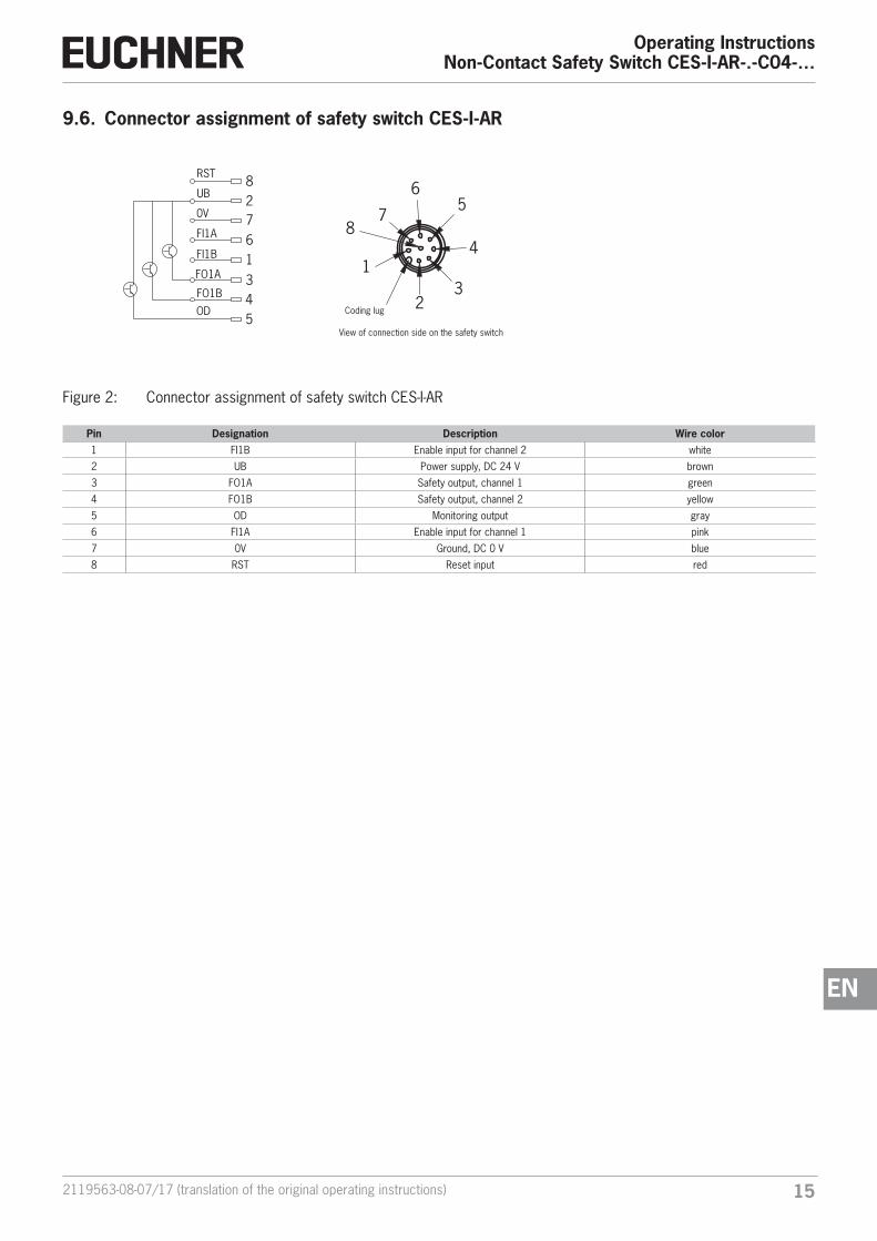
9.6. Connector assignment of safety switch CES-I-AR
Coding lug
1
7
65
4
32
8
82761345
UB
0V
FI1A
FI1B
FO1A
FO1B
OD
RST
View of connection side on the safety switch
Figure 2: Connector assignment of safety switch CES-I-AR
Pin Designation Description Wire color1 FI1B Enable input for channel 2 white
2 UB Power supply, DC 24 V brown
3 FO1A Safety output, channel 1 green
4 FO1B Safety output, channel 2 yellow
5 OD Monitoring output gray
6 FI1A Enable input for channel 1 pink
7 0V Ground, DC 0 V blue
8 RST Reset input red

Operating InstructionsNon-Contact Safety Switch CES-I-AR-.-C04-…
16 (translation of the original operating instructions) 2119563-08-07/17
9.7. Connector assignment of Y-distributor
M12x1
max
. 45
Ø 14,5
Strapping plug 097645 4-pin, plug
(figure similar)
Y-distributor with connection cable 111696 or 112395
Socket
Plug Socket
Pin Function
X2.1 UB
X2.2 FO1A
X2.3 0 V
X2.4 FO1B
X2.5 RST
Pin Function
X3.1 UB
X3.2 FI1A
X3.3 0 V
X3.4 FI1B
X3.5 RST
12
12
097627
45°
15,1
4 85
6
3 12
7
35,1
20,5
1
24
5
3 3
4
2
1
5
M x1
Ø 14,6
M x1
()
Y-distributor 097627
Socket
Connector assignment of safety switch CES-I-AR
(8-pin plug) and
Y-distributor (8-pin socket)
Pin Function
X1.1 FI1B
X1.2 UB
X1.3 FO1A
X1.4 FO1B
X1.5 OD
X1.6 FI1A
X1.7 0 V
X1.8 RST
Plug Socket
M12x1
44
4541
15
M12x1
15 15
M12x1
33
A
B
4
8
56
3
1
2
7
1
2
4
5
3 3
4
2
1
5
Leng
th l Order no. Lengthl [mm]
111696 200
112395 1,000
Pin Function
X2.1 UB
X2.2 FO1A
X2.3 0 V
X2.4 FO1B
X2.5 RST
Pin Function
X3.1 UB
X3.2 FI1A
X3.3 0 V
X3.4 FI1B
X3.5 RST

172119563-08-07/17 (translation of the original operating instructions)
Operating InstructionsNon-Contact Safety Switch CES-I-AR-.-C04-…
EN
9.8. Connection of a single AR deviceIf a single AR device is used, connect the device as shown in Figure 3. Monitoring outputs can be routed to a control system.
The switch can be reset via the RST input. To do this, a voltage of 24 V is applied to the RST input for at least 3 seconds. The RST input must be connected to 0 V if it is not used.
WARNING
In case of an error, loss of the safety function through incorrect connection. Ì To ensure safety, both safety outputs (FO1A and FO1B) must always be evaluated.
Important!
The example shows only an excerpt that is relevant for connection of the CES system. The example illustrated here does not show complete system planning. The user is responsible for safe integration in the overall system. Detailed application examples can be found at www.euchner.com. Simply enter the order number in the search box. All available connection examples for the device can be found under “Downloads.”
SafetyOutputs
Monitoring Output
Read
Hea
d
-B1 UB
2
FI1A
6
FI1B
1
7
0V
5
OUT
3
FO1A
4
FO1B
RST
8
CES
Safety Inputs
24 V DC
GND
-F1
Connected load
-S1
Figure 3: Connection example for separate operation of a CES-I-AR-…

Operating InstructionsNon-Contact Safety Switch CES-I-AR-.-C04-…
18 (translation of the original operating instructions) 2119563-08-07/17
9.9. Connection of several devices in a switch chain
Important!
Ì An AR switch chain may contain a maximum of 20 safety switches. Ì The example shows only an excerpt that is relevant for connection of the CES system. The exam-ple illustrated here does not show complete system planning. The user is responsible for safe in-tegration in the overall system. Detailed application examples can be found at www.euchner.com. Simply enter the order number in the search box. You will find all available connection examples for the device in Downloads.
The series connection is shown here based on the example of the version with plug connectors M12. The switches are con-nected one behind the other with the aid of pre-assembled connection cables and Y-distributors. If a safety door is opened or if a fault occurs on one of the switches, the system shuts down the machine. A higher-level control system cannot, however, detect which safety guard is open or on which switch a fault has occurred with this connection technology. A special AR eval-uation unit is required for this purpose (see chapter 9.10. Information on operation on an AR evaluation unit on page 20).
The series connection can also be realized via additional terminals in a control cabinet.
The safety outputs are permanently assigned to the respective safety inputs of the downstream switch. FO1A must be routed to FI1A and FO1B to FI1B. If the connections are interchanged (e.g. FO1A to FI1B), the device will switch to the fault state.
Always use the RST input in series connections. All switches in a chain can be reset at the same time with this reset input. To do this, a voltage of 24 V must be applied to the RST input for at least 3 seconds. If input RST is not used in your appli-cation, it should be connected to 0 V.
Note the following on this aspect: Ì A common signal must be used for all switches in the chain. This can be a changeover switch or the output of a control system. A button is not suitable because the reset must always be connected to GND during operation (see switch S1 in Figure 4 on page 19). Ì Reset must always be performed simultaneously for all switches of the chain.

192119563-08-07/17 (translation of the original operating instructions)
Operating InstructionsNon-Contact Safety Switch CES-I-AR-.-C04-…
EN
Y-di
strib
utor
Term
inat
ing
plug
1 35 2 4
16
27
85
34
5 2 41 3
RST
0V
FI1A
OUT
FO1BFO1A
UB
FI1B
UB
FO1A0V FO1B
RST
UB
FI1A0V FI1B
RST
2 41U
B
FI1A
FI1B
Safe
ty O
utpu
ts
Read Head
Read Head
Safe
ty O
utpu
tsSa
fety
Inpu
tsSa
fety
Inpu
ts
Y-di
strib
utor
Y-di
strib
utor
Y-di
strib
utor
Term
inat
ing
plug
Eval
Uni
t
Read Head
Safe
ty O
utpu
tsSa
fety
Inpu
ts
5
OU
T
4
FO1B
2
UB
8
RST
6
FI1A
1
FI1B
7
0V
5
OU
T
3
FO1A
4
FO1B
2
UB
8
RST
6
FI1A
1
FI1B
7
0V
0V
3
FO1A
4
FO1B
-S1
12
1114
2
UB
8
RST
6
FI1A
1
FI1B
7
0V
5
OU
T
3
FO1A
24V
CES
CES
CES
Figure 4: Connection example for series connection with reset and changeover switch
Operating InstructionsNon-Contact Safety Switch CES-I-AR-.-C04-…
20 (translation of the original operating instructions) 2119563-08-07/17
9.10. Information on operation on an AR evaluation unitThe devices can be operated on an AR evaluation unit. Please refer to the operating instructions for the relevant AR evalu-ation unit for more information.
9.11. Notes on operation with safe control systemsPlease observe the following requirements for connection to safe control systems: Ì Use a common power supply for the control system and the connected safety switches. Ì A pulsed power supply must not be used for UB. Tap the supply voltage directly from the power supply unit. If the supply voltage is connected to a terminal of a safe control system, this output must provide sufficient electrical current. Ì Always connect inputs FI1A and FI1B directly to a power supply unit or to outputs FO1A and FO1B of another EUCHNER AR device (series connection). Pulsed signals must not be present at inputs FI1A and FI1B. Ì The safety outputs (FO1A and FO1B) can be connected to the safe inputs of a control system. Prerequisite: The input must be suitable for pulsed safety signals (OSSD signals, e.g. from light curtains). The control system must tolerate test pulses on the input signals. This normally can be set up by parameter assignment in the control system. Observe the notes of the control system manufacturer. For the test-pulse duration of your safety switch, please refer to chapter 12. Technical data on page 25.
A detailed example of connecting and setting the parameters of the control system is available for many devices at www.euchner.com in the area Download » Applications » CES. The features of the respective device are dealt with there in greater detail.

212119563-08-07/17 (translation of the original operating instructions)
Operating InstructionsNon-Contact Safety Switch CES-I-AR-.-C04-…
EN
Safe
ty O
utpu
t
Read Head
Safe
tyIn
puts
Read Head
Safe
ty O
utpu
tSa
fety
Inpu
tsSa
fety
Inpu
tsSa
fety
Out
put
Y-di
strib
utor
Y-di
strib
utor
Y-di
strib
utor
Term
inat
ing
plug
ET20
0
4/8
F-D
I4
F-D
O
-X1
-X1
Dig
ital
Out
put
PWR
Supp
ly o
fth
e co
ntro
l
DI4
DI0
DO
..MD
O..P
DO
2
DC2
4V
3
M
2
UB
8
RST
6
FI1A
1
FI1B
X2:3LE
D1 X2
:4UCM
X2:5J
7
0V
5
OU
T
3
FO1A
4
FO1B
X2:10V
(UCM
)
2
UB
8
RST
6
FI1A
1
FI1B
7
0V
5
OU
T
3
FO1A
4
FO1B
2
UB
8
RST
6
FI1A
1
FI1B
7
0V
5
OU
T
3
FO1A
4
FO1B
24V
0V
CES
CET
CES
Figure 5: Connection example for mixed series connection (2 x CES and 1 x CET) to ET200

Operating InstructionsNon-Contact Safety Switch CES-I-AR-.-C04-…
22 (translation of the original operating instructions) 2119563-08-07/17
10. Setup10.1. LED displaysYou will find a detailed description of the signal functions in chapter 11. System status table CES-I-AR-… on page 24.
LED Color
STATE green
DIA red
10.2. Teach-in function for actuator (only for unicode evaluation)The actuator must be allocated to the safety switch using a teach-in function before the system forms a functional unit.
During a teach-in operation, the safety outputs and the monitoring output OD are switched off, i.e. the system is in the safe state.
Tip!
It is recommended to perform the teach-in operation prior to mounting. Mark switches and actuators that belong together in order to avoid confusion. For devices to be connected in series, we recommend performing the teach-in operation separately for each device prior to series connection.
Important!
Ì The teach-in operation may be performed only if the device functions flawlessly. The red DIA LED must not be illuminated. Ì The safety switch disables the code of the previous actuator if teach-in is carried out for a new actuator. Teach-in is not possible again immediately for this actuator if a new teach-in operation is carried out. The disabled code is released again in the safety switch only after a third code has been taught. Ì The safety switch can be operated only with the last actuator taught. Ì The number of teach-in operations is unlimited. Ì If the switch detects the actuator that was most recently taught when in teach-in standby state, this state is ended immediately and the switch changes to normal state. Ì If the actuator to be taught in is within the operating distance for less than 60 s, it will not be acti-vated and the most recently taught in actuator will remain saved.
10.2.1. Preparing device for the teach-in operation and teaching in actuator
1. Apply operating voltage to the safety switch.
¨ The green LED flashes quickly (approx. 5 Hz) A self-test is performed during this time (approx. 8 s). After this, the LED flashes cyclically three times and signals that it is in standby state for teach-in. Standby state for teach-in remains active for approx. 3 minutes.
2. Move new actuator to the read head (observe distance < Sao).
¨ Teach-in operation starts, green LED flashes (approx. 1 Hz). During teach-in, the safety switch checks whether the actuator is a disabled actuator. If this is not the case, the teach-in operation is completed after approx. 60 seconds, the green LED goes out. The new code has been saved, the old code disabled.
3. To activate the new actuator code from the teach-in operation in the safety switch, the operating voltage to the safety switch must then be switched off for min. 3 seconds.
LEDs

232119563-08-07/17 (translation of the original operating instructions)
Operating InstructionsNon-Contact Safety Switch CES-I-AR-.-C04-…
EN
10.2.2. Teach-in function with series connection, replacing and teaching in device
It is recommended not to teach in the actuators in the series connection but to teach them in one by one instead. Teach-in in a series connection works analogously to separate operation in principle. All switches in the chain can be taught in at the same time. The prerequisite is that the switch chain functions without problems and the following steps are followed. Further steps might have to be observed for mixed switch chains (e.g. for chains with CES and safety switches with guard locking). Observe the operating instructions for the other devices in the chain for this purpose.
Work on the wiring (e.g. during device replacement) should generally be performed in a de-energized state. On certain systems, it is nevertheless necessary to perform this work and subsequent teach-in during ongoing operation.
Input RST must be connected as shown in Figure 4 on page 19 to permit this.
Proceed as follows:
1. Open the safety guard on which the switch or actuator is to be replaced.
2. Mount the new switch or actuator and prepare it for the teach-in operation (see chapter 10.2.1. Preparing device for the teach-in operation and teaching in actuator on page 22).
3. Close all safety guards in the chain.
4. Actuate the reset for at least 3 s (24 V on RST).
¨ On the safety switch that is positioned at a new actuator, the green LED flashes at approx. 1 Hz and the actuator is taught in. This takes approx. 1 min. Do not switch off during this time and do not actuate reset! The teach-in operation has ended when all LEDs on the device are off.
5. Actuate the reset for at least 3 s (24 V on RST).
¨ The system restarts and then continues to function in normal operation.
10.3. Functional check
WARNING
Danger of fatal injury as a result of faults in installation and functional check. Ì Before carrying out the functional check, make sure that there are no persons in the danger area. Ì Observe the valid accident prevention regulations.
10.3.1. Electrical function test
After installation and any fault, the safety function must be fully checked. Proceed as follows:
1. Switch on operating voltage.
¨ The machine must not start automatically.
¨ The safety switch carries out a self-test. The green STATE LED flashes for 8 s at 5 Hz. The green STATE LED then flashes at regular intervals.
2. Close all safety guards.
¨ The machine must not start automatically.
¨ The green STATE LED illuminates continuously.
3. Enable operation in the control system.
4. Open the safety guard. Ì The machine must switch off and it must not be possible to start it as long as the safety guard is open. Ì The green STATE LED flashes at regular intervals.
Repeat steps 2 - 4 for each safety guard.

Operating InstructionsNon-Contact Safety Switch CES-I-AR-.-C04-…
24 (translation of the original operating instructions) 2119563-08-07/17
11. System status table CES-I-AR-…
Operating modeAc
tuat
or/d
oor
po-
sitio
n
Safe
ty o
utpu
ts F
O1A
an
d FO
1B
Mon
itori
ng o
utpu
t OD LED indicator
Output
State
STAT
E (g
reen
)
DIA
(red
)
Self-test X off off 5 Hz (8 s) Self-test after power-up
Normal operation
closed on on Normal operation, door closed, safety outputs on the preceding device in the switch chain switched on
closed on on
Flash burst
inverted 5 x
Normal operation, door closed, actuator in the limit range ¨ Re-adjust door
closed off on 1 x in-verse
Normal operation, door closed, safety outputs on the preceding device in the switch chain switched off
open off off 1 x Normal operation, door open
open off off 2 x Normal operation, door open; no actuator was taught in successfully during initial setup
Teach-inoperation(only unicode)
open off off 3 x Door open, device is ready for teach-in for another actuator (only short time after power-up)
closed off off 1 Hz Teach-in operation
X off off Positive acknowledgment after completion of teach-in operation
Fault display
X off off 2 x Input fault (e.g. missing test pulses, illogical switch state from previous switch in the switch chain)
closed off off 3 x Defective actuator (e.g. fault in code or code not readable)
X off off 4 x Output fault (e.g. short circuits, loss of switching ability)
X off off Internal fault (e.g. component faulty, data error)
Key to symbols
LED not illuminated
LED illuminated
5 Hz (8 s) LED flashes for 8 at 5 Hz
3 x LED flashes three times, and this is then repeated
X Any state
After the cause has been remedied, faults can generally be reset by opening and closing the safety guard. If the fault is still displayed afterward, use the reset function or briefly interrupt the power supply. Please contact the manufacturer if the fault could not be reset after restarting.
Important!
If you do not find the displayed device status in the system status table, this indicates an internal device fault. In this case, you should contact the manufacturer.

252119563-08-07/17 (translation of the original operating instructions)
Operating InstructionsNon-Contact Safety Switch CES-I-AR-.-C04-…
EN
12. Technical dataNOTICE
If a data sheet is included with the product, the information on the data sheet applies.
12.1. Technical data of safety switch CES-I-AR-C04-…Parameter Value Unit
min. typ. max.Housing material PBT plasticDimensions 42 x 25 x 18 mmWeight (device without connection cable) 0.08 kgAmbient temperature at UB = DC 24 V - 25 - + 65
°CStorage temperature - 40 - + 70Degree of protection IP67
IP69K (only version with flying lead and version with plug connector M8 and mating connector with the same degree of protection)
Safety class IIIDegree of contamination 3Installation position AnyInstallation method Non-flushConnection - Plug connector M8, 8-pin, or
- Connection cable PUR, 0.14 mm², with plug connector M12, 8-pin, or- Connection cable PUR with flying lead, 8 x 0.14 mm²
Operating voltage UB (regulated, residual ripple < 5%) 24 ± 15% (PELV) V DCCurrent consumption 35 mAExternal fuse (operating voltage) 0.25 - 8 A
Safety outputs FO1A/FO1B Semiconductor outputs, p-switching, short circuit-proof- Output voltage U(FO1A)/U(FO1B) 1)
HIGH U(FO1A)UB-1.5 - UB
V DC HIGH U(FO1B)
LOW U(FO1A)/U(FO1B) 0 1
Switching current per safety output 1 - 200 mAUtilization category according to EN IEC 60947-5-2 DC-13 24 V 200 mA
Caution: outputs must be protected with a free-wheeling diode in case of inductive loads.Off-state current Ir ≤ 0.25 mAMonitoring output OD 1) p-switching, short circuit-proof- Output voltage 0.8 x UB - UB V DC- Max. load - - 50 mARated insulation voltage Ui - - 300 VRated impulse withstand voltage Uimp - - 1.5 kVConditional short-circuit current 100 AResilience to vibration Acc. to EN IEC 60947-5-2Switching frequency - - 1 HzRepeat accuracy R ≤ 10 %EMC protection requirements Acc. to EN IEC 60947-5-3 and EN IEC 61326-3-1Ready delay - 8 - sRisk time for single device - - 260 msRisk time delay per device 5 msSwitch-on time - - 400 msDiscrepancy time - - 10 msTest-pulse duration 1 msTest-pulse interval 140 msReliability values according to EN ISO 13849-1Category 4Performance Level PL ePFHD 4.1 x 10 -9 / hMission time 20 years
1) Values at a switching current of 50 mA without taking into account the cable length.

Operating InstructionsNon-Contact Safety Switch CES-I-AR-.-C04-…
26 (translation of the original operating instructions) 2119563-08-07/17
12.1.1. Typical system times
Please refer to the technical data for the exact values.
Ready delay: After switching on, the device carries out a self-test. The system is ready for operation only after this time.
Switch-on time of safety outputs: The max. reaction time ton is the time from the moment when the actuator is in the operating distance to the moment when the safety outputs switch on.
Simultaneity monitoring, safety inputs FI1A/FI1B: If the safety inputs have different switching states over a certain time, the safety outputs (FO1A and FO1B) will be switched off. The devices switches to fault state.
Risk time according to EN 60947-5-3: If an actuator moves outside the operating distance, the safety outputs (FO1A and FO1B) are switched off after the risk time at the latest.
If several devices are operated in a series connection, the risk time of the overall device chain will increase with each device added. Use the following calculation formula:
tr = tr, e + (n x tl)
tr = Total risk time
tr, e = Risk time, single device (see technical data)
tl = Risk time delay per device
n = Number of additional devices (total number -1)
Discrepancy time: The safety outputs (FO1A and FO1B) switch with a slight time offset. They have the same signal state no later than after the discrepancy time.
Test pulses at the safety outputs: The device generates its own test pulses on the safety outputs (FO1A and FO1B). A downstream control system must tolerate these test pulses.
This can usually be set up in the control systems by parameter assignment. If parameter assignment is not possible for your control system or if shorter test pulses are required, please contact our support organization.
The test pulses are also output when the safety outputs are switched off.

272119563-08-07/17 (translation of the original operating instructions)
Operating InstructionsNon-Contact Safety Switch CES-I-AR-.-C04-…
EN
12.1.2. Dimension drawing of safety switch CES-I-AR-C04-…
10,6
M12x1
42
4,1 29
,225
832
10,6
4,1
12,9
15,5
14,5
4,8
18Active face
LEDs
Active face
LEDs
With M8 plug connector
Connection cable with flying lead
Connection cable with M12 plug connector
Rubber support(included)
With rubber support

Operating InstructionsNon-Contact Safety Switch CES-I-AR-.-C04-…
28 (translation of the original operating instructions) 2119563-08-07/17
12.2. Technical data of actuator CES-A-BBN-C04/CES-A-BBN-C04-EX-137527Parameter Value Unit
min. typ. max.
Housing material PBT plastic
Dimensions 42 x 25 x 18 mm
Weight 0.03 kg
Ambient temperature - 40 - + 65 °C
Degree of protection IP67/IP69K
Installation position Active face opposite read head
Power supply Inductive via read head
12.2.1. Dimension drawing
Active face
4,5
32
14
25
42
6
14,5
18
15,5 With rubber support
Rubber support
NOTICE
Ì Two safety screws M4x20 included. Ì Rubber support included.
12.2.2. Switching distances
Operating distance for center offset m = 0
Approach direction Parameter Value Unit
A B min. typ. max.
Switch-on distance - 15 -
mm
Assured switch-on distance sao 1) 10 - -
Switching hysteresis 1) 1 2 -
Assured switch-off distance sar- in x/z direction- in y direction
--
--
4060
1) On approach in Z direction
Approach direction Parameter Value Unit
C D min. typ. max.
Switch-on distance - 11 -
mm
Assured switch-on distance sao 1) 6 - -
Switching hysteresis 1) 1 2 -
Assured switch-off distance sar- in x/z direction- in y direction
--
--
4060
1) On approach in x direction
292119563-08-07/17 (translation of the original operating instructions)
Operating InstructionsNon-Contact Safety Switch CES-I-AR-.-C04-…
EN
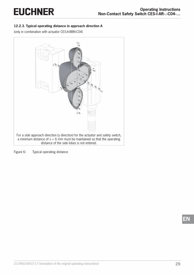
12.2.3. Typical operating distance in approach direction A
(only in combination with actuator CES-A-BBN-C04)
-25-30
X
105
1520
-20
-25
-30
-40
-35
-15
-10
-5
-10
20
25
30
15
10
40
35
5
Y
-5
-15
-20
Z
1015
2025
5
30
For a side approach direction (y direction) for the actuator and safety switch, a minimum distance of s = 6 mm must be maintained so that the operating
distance of the side lobes is not entered.
Figure 6: Typical operating distance

Operating InstructionsNon-Contact Safety Switch CES-I-AR-.-C04-…
30 (translation of the original operating instructions) 2119563-08-07/17
12.3. Technical data of actuator CES-A-BDN-06Parameter Value Unit
min. typ. max.
Housing material Macromelt PA-based plastic
Dimensions 26 x ∅ 6 mm
Weight 0.005 kg
Ambient temperature - 40 - + 70 °C
Degree of protection acc. to EN IEC 60529 IP67 / IP69K 1)
Installation position Active face opposite read head
Power supply Inductive via read head
1) With flush installation
12.3.1. Dimension drawingInstallation options
26 0+0,5
Ø 3
0 *
min
.
30 *30 *
6,1 0+0,1
6
* Metal-free zone
Operating distance
C
A
Approach direction
CAUTION
Ì Do not mount at temperatures below 0 °C. Ì The actuator can be damaged during mounting.
12.3.2. Switching distances
Operating distance for center offset m = 0
Approach direction Parameter Value Unit
A min. typ. max.
Switch-on distance - 19 -
mm
Assured switch-on distance sao 1) 14 - -
Switching hysteresis 1) - 2 -
Assured switch-off distance sar- in x/z direction- in y direction
--
--
4060
1) The values apply to surface installation of the actuator
Approach direction Parameter Value Unit
C min. typ. max.
Switch-on distance - 15 -
mm
Assured switch-on distance sao 1) 10 - -
Switching hysteresis 1) - 2 -
Assured switch-off distance sar- in x/z direction- in y direction
--
--
4060
1) The values apply to surface installation of the actuator

312119563-08-07/17 (translation of the original operating instructions)
Operating InstructionsNon-Contact Safety Switch CES-I-AR-.-C04-…
EN
13. Ordering information and accessoriesTip!
Suitable accessories, e.g. cables or assembly material, can be found at www.euchner.com. To order, enter the order number of your item in the search box and open the item view. Accessories that can be combined with the item are listed under “Accessories”.
14. Inspection and serviceWARNING
Loss of the safety function because of damage to the system. Ì In case of damage, the entire device must be replaced. Ì Only accessories or spare parts that can be ordered from EUCHNER may be replaced.
Regular inspection of the following is necessary to ensure trouble-free long-term operation: Ì Check the switching function (see chapter 10.3. Functional check on page 23) Ì Check the secure fastening of the devices and the connections Ì Check for soiling
No servicing is required; repairs to the device are only allowed to be made by the manufacturer.
NOTICE
The year of manufacture can be seen in the lower right corner of the type label. The current version number in the format (VX.X.X) can also be found on the device.
15. ServiceIf service support is required, please contact:
EUCHNER GmbH + Co. KG
Kohlhammerstraße 16
70771 Leinfelden-Echterdingen
Service telephone:
+49 711 7597-500
E-mail:
Internet:
www.euchner.com

Operating InstructionsNon-Contact Safety Switch CES-I-AR-.-C04-…
32 (translation of the original operating instructions) 2119563-08-07/17
16. Declaration of conformity

332119563-08-07/17 (translation of the original operating instructions)
Operating InstructionsNon-Contact Safety Switch CES-I-AR-.-C04-…
EN

Operating InstructionsNon-Contact Safety Switch CES-I-AR-.-C04-…
34 (translation of the original operating instructions) 2119563-08-07/17

352119563-08-07/17 (translation of the original operating instructions)
Operating InstructionsNon-Contact Safety Switch CES-I-AR-.-C04-…
EN

Euchner GmbH + Co. KGKohlhammerstraße 1670771 [email protected]
Edition:2119563-08-07/17Title: Operating Instructions Non-Contact Safety Switch CES-I-AR-.-C04-… (translation of the original operating instructions)Copyright:© EUCHNER GmbH + Co. KG. 07/2017
Subject to technical modifications; no responsibility is accept-ed for the accuracy of this information.


