Non-contact open linear encoders - Fagor Automation · PATENT PENDING PATENT PENDING Fagor...
32
Non-contact open linear encoders
Transcript of Non-contact open linear encoders - Fagor Automation · PATENT PENDING PATENT PENDING Fagor...

Non-contact open l inear encoders

Over 35 years of continuous evolution
Non-contact open l inear encoders

PATENT PENDING
PATENT PENDING
Fagor Automation has been manufacturing high quality linear and rotary encoders using precision optical technology for more than 35 years.
Over the years Fagor has created, developed and patented systems, components and technologies that allow us to offer best quality and features over the complete range of product utilizing innovative production methods.
Hence making Fagor Automation the most efficient alternative in the world of feedback systems.
SIR reference marks Single-window scanning
Modern facil ities and innovative processes
With state-of-the-art technology
In order to ensure quality and reliability in all its products Fagor Automation utilizes the most
advanced technology and testing and manufacturing facilities. From centralized computer
control temperature monitoring, cleanliness and relative humidity control, a must for the
feedback system manufacturing process, to laboratories for climate, vibration and EMC
testing to certify the designs.
Fagor Automation’s commitment to this technology and quality is evident by creation of
Aotek in 2002, a dedicated research center providing various technological breakthroughs.
This investment has resulted in large number of patents and customized solutions in
electrical, optical and mechanical fields.

Superior technology and innovative design
Fagor Automation develops with maximum professionalism the three
cornerstones in encoder design: optical design, electronic design and
mechanical design that result in a state-of-the-art product.
Optical designIn the vanguard of measuring technology, Fagor Automation uses
transmission and reflective optics in its range of encoders.
With new scanning techniques, such as the new single-window scanning
technology , more immune to contamination, which is critical for
operations in extreme conditions, and contributes to attaining high quality
signals that minimize interpolation errors, resulting in improved accuracy of
the measurement system.
Electronic designFagor Automation uses latest generation integrated electronic
components in their design. Owing to that, the optimization of the signals
at high traversing speeds is achieved, with micrometric accuracy and
nanometric resolution.
Mechanical designFagor Automation designs and manufactures the most innovative and
reliable measuring systems using its advanced mechanical designs.
These designs, together with the materials used contribute to the required
product robustness to ensure the best performance in their different
applications.
LED Linear encoder
Analyzer PhotodiodesProjected
light

ABSOLUTE
INCREMENTAL
Technology .................................................................................. 6
Signals ................................................................................................. 7
Range ................................................................................................... 8
Absolute EXA series (adhesive) ................... 10
Absolute EXG series (guided) .......................... 12
Absolute EXT series (tensioned) ................. 14
Cables and extension cables .......................... 16
Technology .................................................................................. 18
Signals .................................................................................................. 18
Range ................................................................................................... 20
Incremental EXA series (adhesive) .......... 22
Incremental EXG series (guided) ................. 24
Incremental EXT series (tensioned) ........ 26
Cables and extension cables ........................... 28
Accessories ............................................................................... 31

6
A B S O L U T E
The absolute measurement system is a direct digital measure of machine position. It is fast, accurate and does not require homing of the machine. The position value is available from the moment the machine is turned on and may be requested by the connected device (CNC) at any time.
The absolute encoders provide direct measure of machine position without using any intermediate device. The positioning errors originating from machine mechanics are minimized as the encoder is directly mounted to the machine surface and the guide ways. Some of the potential sources of such errors in a machine tool such as lead screw pitch, certain amount of backlash and thermal behavior can be minimized using these encoders.
L inear EncodersFagor’s non-contact open absolute linear encoders use the auto imaging principle which uses diffuse light reflected from the graduated steel tape. The reading system consists of an LED, as the light source of the linear encoder; a reticule that makes the image and a monolithic photo detector element in the plane of the image especially designed and patented by Fagor Automation.
The measuring method has two different etchings:
• Incremental graduation: Used to generate incremental signals that are counted inside the reader head.
• Absolute graduation: It is a binary code with a special sequence that avoids repetition all along the measuring length of the encoder.
On Fagor absolute encoders, the absolute position is calculated using the data of that code read by means of a high precision optical sensor.
Technology
Single-body reader head
Incorporated cable
Graduated steel scale
Tensor: tensioned model
Aluminum guide: guided or tensioned model
Side mount option
LED
Non-contact open designThe open design allows transmitting the machine movement and reading its position accurately and without contact; therefore without friction between the reader head and the graduated scale. All the electronics, including interpolation, is integrated into the reader head. The technology used provides a robust and compact solution with high accuracy and resolution at high speed.
Graduated steel encoder
absolute digital output
incremental LED
absolute LED
absolute LED
incremental graduation
absolute graduation
incremental sensor
absolute sensors
steel encoder
reader head
CNC /PC / Drivecontroller
7
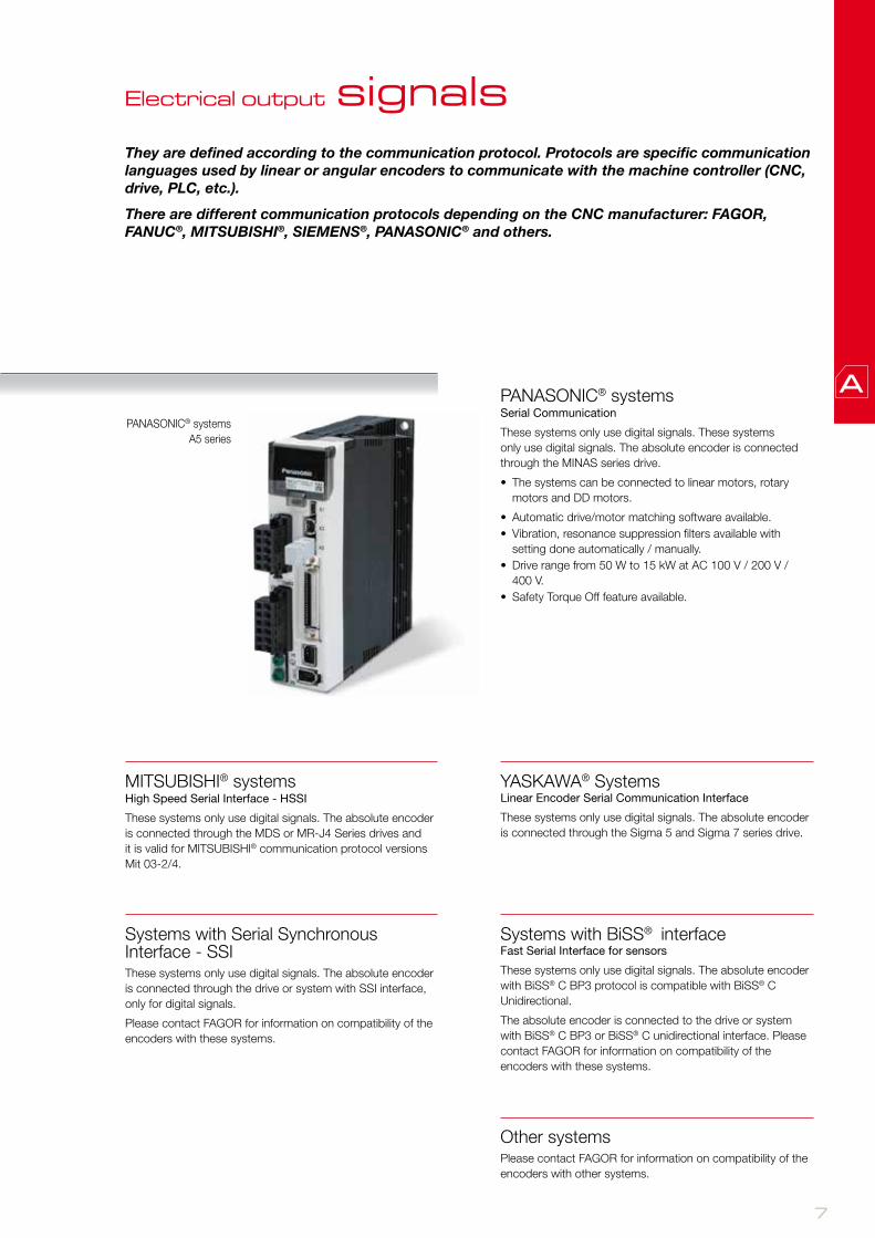
They are defined according to the communication protocol. Protocols are specific communication languages used by linear or angular encoders to communicate with the machine controller (CNC, drive, PLC, etc.).
There are different communication protocols depending on the CNC manufacturer: FAGOR, FANUC®, MITSUBISHI®, SIEMENS®, PANASONIC® and others.
Electrical output signals
PANASONIC® systems Serial Communication
These systems only use digital signals. These systems only use digital signals. The absolute encoder is connected through the MINAS series drive.
• The systems can be connected to linear motors, rotary motors and DD motors.
• Automatic drive/motor matching software available. • Vibration, resonance suppression filters available with
setting done automatically / manually.• Drive range from 50 W to 15 kW at AC 100 V / 200 V /
400 V. • Safety Torque Off feature available.
MITSUBISHI® systems High Speed Serial Interface - HSSI
These systems only use digital signals. The absolute encoder is connected through the MDS or MR-J4 Series drives and it is valid for MITSUBISHI® communication protocol versions Mit 03-2/4.
PANASONIC® systems A5 series
YASKAWA® Systems Linear Encoder Serial Communication Interface
These systems only use digital signals. The absolute encoder is connected through the Sigma 5 and Sigma 7 series drive.
Systems with Serial Synchronous Interface - SSIThese systems only use digital signals. The absolute encoder is connected through the drive or system with SSI interface, only for digital signals.
Please contact FAGOR for information on compatibility of the encoders with these systems.
Systems with BiSS® interface Fast Serial Interface for sensors
These systems only use digital signals. The absolute encoder with BiSS® C BP3 protocol is compatible with BiSS® C Unidirectional.
The absolute encoder is connected to the drive or system with BiSS® C BP3 or BiSS® C unidirectional interface. Please contact FAGOR for information on compatibility of the encoders with these systems.
Other systemsPlease contact FAGOR for information on compatibility of the encoders with other systems.

8
A B S O L U T E
Analyze the application to make sure that the proper encoder will be selected for the machine.To do this, bear in mind the following considerations:
InstallationConsider the physical length of the installation and the space available for it.
These aspects are crucial to determine the type of linear encoder to use.
Mechanical Design:EXA: adhesive model with the smallest cross section for constraint spaces, it consists of an engraved steel tape glued directly onto the machine surface, recommended if the tape is under thermally stable conditions.
EXG: guided model for long measuring lengths it comprises an aluminium extrusion glued to the surface and an engraved steel tape. The steel tape is guided in the extrusion and secured in the mid point to the machine surface that allows the tape to expand/contract freely at its ends and ensures a defined thermal behaviour.
EXT: tensioned model for very long measuring lengths and high accuracy it comprises an aluminium extrusion glued or screwed to the surface, an engraved steel tape and tensioning system. The steel tape is guided in the extrusion and tensioned between its ends. The tensioned steel tape is fixed on the machine base so it replicates the thermal behaviour of the surface.
AccuracyEach linear encoder is subjected to quality control showing its accuracy along its measuring length.
SignalThe signal selection considers the communication protocols compatible with the main CNC manufacturers.
ResolutionThe resolution of the control of machine depends on the linear encoder.
Cable lengthThe length of the cable depends on the type of signal.
CompatibilityThe signal must be compatible with the control system.
SpeedThe speed requirements for the application must be analyzed before choosing the linear encoder.
Shock and VibrationFagor linear encoders withstand vibrations of up to 200 m/s2 and shocks of up to 1000 m/s2.
Range
Series Section Measuring lengths Accuracy SignalsPitchResolution up to
Model
Absolute EXA
Adhesive
70 mm up to 3 020 mm (*) ± 10 µm/m
SSI 0.01 µm TAA + L2A
PANASONIC® 0.01 µm TAA + L2AP
MITSUBISHI® 0.01 µm TAA + L2AM / L2AM2
BiSS® 0.01 µm TAA + L2AB
YASKAWA® 0.009765625 µm TAA + L2AK
Absolute EXG
Guided
240 mm up to 3 040 mm (*) ± 10 µm/m
SSI 0.01 µm PG+TGA + L2A
PANASONIC® 0.01 µm PG+TGA + L2AP
MITSUBISHI® 0.01 µm PG+TGA + L2AM / L2AM2
BiSS® 0.01 µm PG+TGA + L2AB
YASKAWA® 0.009765625 µm PG+TGA + L2AK
Absolute EXT
Tensioned
140 mm up to 3 040 mm (*) ± 5 µm/m
SSI 0.01 µm PT + TTA + L2A
PANASONIC® 0.01 µm PT + TTA + L2AP
MITSUBISHI® 0.01 µm PT + TTA + L2AM / L2AM2
BiSS® 0.01 µm PT + TTA + L2AB
YASKAWA® 0.009765625 µm PT + TTA + L2AK

9
(*) contact Fagor Automation for other lengths.
Series Section Measuring lengths Accuracy SignalsPitchResolution up to
Model
Absolute EXA
Adhesive
70 mm up to 3 020 mm (*) ± 10 µm/m
SSI 0.01 µm TAA + L2A
PANASONIC® 0.01 µm TAA + L2AP
MITSUBISHI® 0.01 µm TAA + L2AM / L2AM2
BiSS® 0.01 µm TAA + L2AB
YASKAWA® 0.009765625 µm TAA + L2AK
Absolute EXG
Guided
240 mm up to 3 040 mm (*) ± 10 µm/m
SSI 0.01 µm PG+TGA + L2A
PANASONIC® 0.01 µm PG+TGA + L2AP
MITSUBISHI® 0.01 µm PG+TGA + L2AM / L2AM2
BiSS® 0.01 µm PG+TGA + L2AB
YASKAWA® 0.009765625 µm PG+TGA + L2AK
Absolute EXT
Tensioned
140 mm up to 3 040 mm (*) ± 5 µm/m
SSI 0.01 µm PT + TTA + L2A
PANASONIC® 0.01 µm PT + TTA + L2AP
MITSUBISHI® 0.01 µm PT + TTA + L2AM / L2AM2
BiSS® 0.01 µm PT + TTA + L2AB
YASKAWA® 0.009765625 µm PT + TTA + L2AK

10
A B S O L U T EA B S O L U T E
EXA seriesA D H E S I V E
Non-contact open linear encoder for high accuracy, high speed applications.
It consists of a compact reader head with all the electronics and optics integrated into a single body that may be mounted from the side or from the top.
It has an LED to help mounting it and includes a 1 or 3 meter cable with a connector, a 10 mm wide adhesive reflective stainless steel tape that is highly resistant to solvents.
Model descriptionTAA + L2A: non-contact open linear connector with a reader head that
uses SSI protocol and an adhesive absolute tape.
TAA + L2AM: non-contact open linear connector with a reader head that uses MITSUBISHI® CNC full duplex protocol and an adhesive absolute tape.
TAA + L2AM2: non-contact open linear connector with a reader head that uses MITSUBISHI® CNC half duplex protocol and an adhesive absolute tape.
TAA + L2AP: non-contact open linear connector with a reader head that uses PANASONIC® (Matsushita) protocol and an adhesive absolute tape.
TAA + L2AB: non-contact open linear connector with a reader head that uses BiSS® protocol and an adhesive absolute tape.
TAA + L2AK: non-contact open linear connector with a reader head that uses YASKAWA® protocol and an adhesive absolute tape.
Measuring lengths in millimeters
Available from 70 mm to 3,020 mm in 50 mm (*) increments.
(*) Contact Fagor Automation for other lengths.
Characteristics
TAA + L2A TAA + L2AM / L2AM2 TAA + L2AP TAA + L2AB TAA + L2AK
Measurement Incremental: By means of a 20 µm-pitch stainless steel tapeAbsolute: Optical reading of sequential binary code
Steel tape thermal expansion coefficient αtherm: ≈ 11 ppm/K.
Measuring resolution 0.01 μm / 0.05 μm 0.01 μm / 0.05 μm 0.01 μm / 0.05 μm 0.01 μm / 0.05 μm 0.009765625 µm / 0.078125 µm
Maximum speed 480 m/min
Maximum cable length 75 m (*) 30 m 30 m (**) 50 m
Supply voltage 5V ± 10%. < 250 mA (without load)
Reader head 1 or 3 meter cable with a connector
Reader head protection IP 40
Accuracy ± 10 µm/m
Maximum vibration 200 m/s2 (55 … 2000 Hz) IEC 60068-2-6
Maximum shock 1000 m/s2 (11 ms) IEC 60068-2-27
Operating temperature 0°C … 50°C
Storage temperature -20°C ... 70°C
Weight 0.17 kg + 0.025 kg/m
Relative humidity 20 … 80%
(**) Contact Fagor Automation for maximum cable length.
11
AB
SO
LU
TE
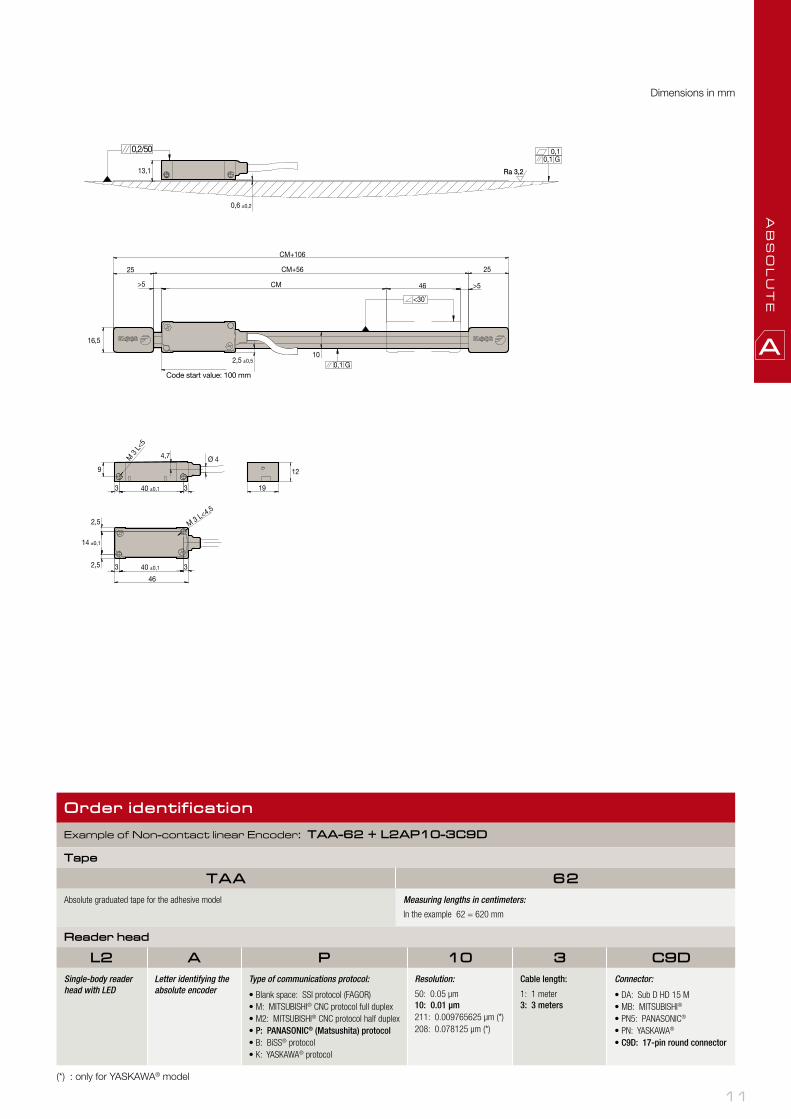
Dimensions in mm
Order identif ication
Example of Non-contact linear Encoder: TAA-62 + L2AP10-3C9D
Tape
TAA 62Absolute graduated tape for the adhesive model Measuring lengths in centimeters:
In the example 62 = 620 mm
Reader head
L2 A P 10 3 C9DSingle-body reader head with LED
Letter identifying the absolute encoder
Type of communications protocol:
• Blank space: SSI protocol (FAGOR)• M: MITSUBISHI® CNC protocol full duplex• M2: MITSUBISHI® CNC protocol half duplex• P: PANASONIC® (Matsushita) protocol• B: BiSS® protocol• K: YASKAWA® protocol
Resolution:
50: 0.05 μm10: 0.01 μm211: 0.009765625 μm (*)208: 0.078125 μm (*)
Cable length:
1: 1 meter3: 3 meters
Connector:
• DA: Sub D HD 15 M• MB: MITSUBISHI®
• PN5: PANASONIC®
• PN: YASKAWA®
• C9D: 17-pin round connector
(*) : only for YASKAWA® model
Code start value: 100 mm

12
A B S O L U T E
EXG seriesG U I D E D
Non-contact open linear encoder for high accuracy, high speed applications.
It consists of a compact reader head with all the electronics and optics integrated into a single body that may be mounted from the side or from the top.
It has an LED to help mounting it and includes a 1 or 3 meter cable with a connector, a 10 mm wide reflective stainless steel tape that is highly resistant to solvents on an adhesive aluminum guide.
Model descriptionPG + TGA + L2A: non-contact open linear connector with a reader head
that uses SSI protocol and a guided absolute tape with an adhesive aluminum guide.
PG + TGA + L2AM: non-contact open linear connector with a reader head that uses MITSUBISHI® CNC full dupllex protocol and a guided absolute tape with an adhesive aluminum guide.
PG + TGA + L2AM2: non-contact open linear connector with a reader head that uses MITSUBISHI® CNC half duplex protocol and a guided absolute tape with an adhesive aluminum guide.
PG + TGA + L2AP: non-contact open linear connector with a reader head that uses PANASONIC® (Matsushita) protocol and a guided absolute tape with an adhesive aluminum guide.
PG +TGA + L2AB: non-contact open linear connector with a reader head that uses BiSS® protocol and a guided absolute tape with an adhesive aluminum guide.
PG + TGA + L2AK: non-contact open linear connector with a reader head that uses YASKAWA® protocol and a guided absolute tape with an adhesive aluminum guide.
Measuring lengths in millimeters
Available from 240 mm to 3,040 mm in 100 mm (*) increments.
CharacteristicsPG + TGA +
L2APG + TGA +
L2AM / L2AM2PG + TGA +
L2APPG + TGA +
L2ABPG + TGA +
L2AK
Measurement Incremental: By means of a 20 µm-pitch stainless steel tapeAbsolute: Optical reading of sequential binary code
Steel tape thermal expansion coefficient αtherm: ≈ 11 ppm/K.
Measuring resolution 0.01 μm / 0.05 μm 0.01 μm / 0.05 μm 0.01 μm / 0.05 μm 0.01 μm / 0.05 μm 0.009765625 µm / 0.078125 µm
Maximum speed 480 m/min
Maximum cable length 75 m (*) 30 m 30 m (**) 50 m
Supply voltage 5V ± 10%. < 250 mA (without load)
Reader head 1 or 3 meter cable with a connector
Reader head protection IP 40
Accuracy ± 10 µm/m
Maximum vibration 200 m/s2 (55 … 2000 Hz) IEC 60068-2-6
Maximum shock 1000 m/s2 (11 ms) IEC 60068-2-27
Operating temperature 0°C … 50°C
Storage temperature -20°C ... 70°C
Weight 0.27 kg + 0.05 kg/m
Relative humidity 20 … 80%
(*) Contact Fagor Automation for other lengths.(**) Contact Fagor Automation for maximum cable length.
13
AB
SO
LU
TE
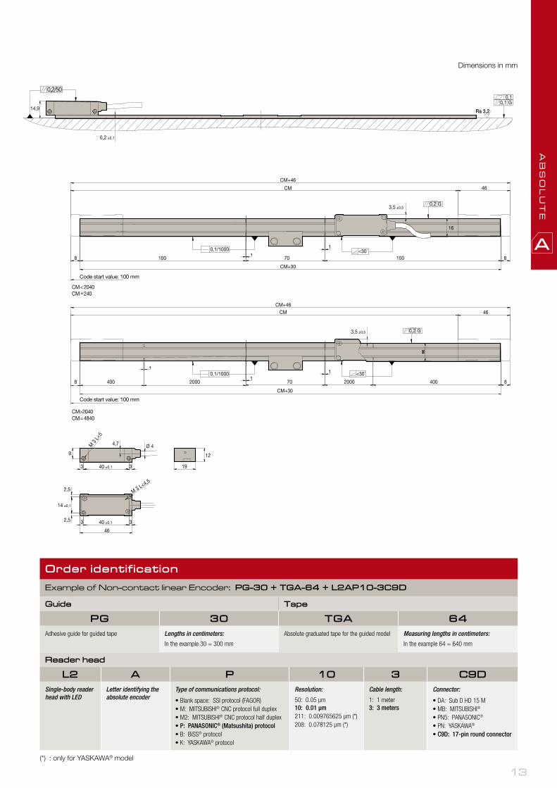
Dimensions in mm
Order identif ication
Example of Non-contact linear Encoder: PG-30 + TGA-64 + L2AP10-3C9D
Guide Tape
PG 30 TGA 64Adhesive guide for guided tape Lengths in centimeters:
In the example 30 = 300 mm
Absolute graduated tape for the guided model Measuring lengths in centimeters:
In the example 64 = 640 mm
Reader head
L2 A P 10 3 C9DSingle-body reader head with LED
Letter identifying the absolute encoder
Type of communications protocol:
• Blank space: SSI protocol (FAGOR)• M: MITSUBISHI® CNC protocol full duplex• M2: MITSUBISHI® CNC protocol half duplex• P: PANASONIC® (Matsushita) protocol• B: BiSS® protocol• K: YASKAWA® protocol
Resolution:
50: 0.05 μm10: 0.01 μm211: 0.009765625 μm (*)208: 0.078125 μm (*)
Cable length:
1: 1 meter3: 3 meters
Connector:
• DA: Sub D HD 15 M• MB: MITSUBISHI®
• PN5: PANASONIC®
• PN: YASKAWA®
• C9D: 17-pin round connector
(*) : only for YASKAWA® model
Code start value: 100 mm
Code start value: 100 mm

14
A B S O L U T E
EXT seriesT E N S I O N E D
Non-contact open linear encoder for high accuracy, high speed applications.
It consists of a compact reader head with all the electronics and optics integrated into a single body that may be mounted from the side or from the top.
It has an LED to help mounting it and includes a 1 or 3 meter cable with a connector, a 10 mm wide reflective stainless steel tape that is highly resistant to solvents on an adhesive or bolted aluminum guide.
Model descriptionPT + TTA + L2A: non-contact open linear connector with a reader head
that uses SSI protocol and a tensioned absolute tape with an adhesive aluminum guide. Indicate PTS for bolted guided.
PT + TTA + L2AM: non-contact open linear connector with a reader head that uses MITSUBISHI® CNC full duplex protocol and a tensioned absolute tape with an adhesive aluminum guide. Indicate PTS for bolted guided.
PT + TTA + L2AM2: non-contact open linear connector with a reader head that uses MITSUBISHI® CNC hald duplex protocol and a tensioned absolute tape with an adhesive aluminum guide. Indicate PTS for bolted guided.
PT + TTA + L2AP: non-contact open linear connector with a reader head that uses PANASONIC® (Matsushita) protocol and a tensioned absolute tape with an adhesive aluminum guide. Indicate PTS for bolted guided.
PT + TTA + L2AB: non-contact open linear connector with a reader head that uses BiSS® protocol and a tensioned absolute tape with an adhesive aluminum guide. Indicate PTS for bolted guided.
PT + TTA + L2AK: non-contact open linear connector with a reader head that uses YASKAWA® protocol and a tensioned absolute tape with an adhesive aluminum guide. Indicate PTS for bolted guided.
Measuring lengths in millimeters
Available from 140 mm to 3,040 mm in 100 mm (*) increments.
CharacteristicsPT + TTA +
L2APT + TTA +
L2AM / L2AM2PT + TTA +
L2APPT + TTA +
L2ABPT + TTA +
L2AK
Measurement Incremental: By means of a 20 µm-pitch stainless steel tapeAbsolute: Optical reading of sequential binary code
Steel tape thermal expansion coefficient αtherm: ≈ 11 ppm/K.
Measuring resolution 0.01 μm / 0.05 μm 0.01 μm / 0.05 μm 0.01 μm / 0.05 μm 0.01 μm / 0.05 μm 0.009765625 µm / 0.078125 µm
Maximum speed 480 m/min
Maximum cable length 75 m (*) 30 m 30 m (**) 50 m
Supply voltage 5V ± 10%. < 250 mA (without load)
Reader head 1 or 3 meter cable with a connector
Reader head protection IP 40
Accuracy ± 5 µm /m
Maximum vibration 200 m/s2 (55 … 2000 Hz) IEC 60068-2-6
Maximum shock 1000 m/s2 (11 ms) IEC 60068-2-27
Operating temperature 0°C … 50°C
Storage temperature -20°C ... 70°C
Weight 0.27 kg + 0.26 kg/m
Relative humidity 20 … 80%
(*) Contact Fagor Automation for other lengths.(**) Contact Fagor Automation for maximum cable length.

15
AB
SO
LU
TE
Dimensions in mm
Reader head
L2 A P 10 3 C9DSingle-body reader head with LED
Letter identifying the absolute encoder
Type of communications protocol:
• Blank space: SSI protocol (FAGOR)• M: MITSUBISHI® CNC protocol full duplex• M2: MITSUBISHI® CNC protocol half duplex• P: PANASONIC® (Matsushita) protocol• B: BiSS® protocol• K: YASKAWA® protocol
Resolution:
50: 0.05 μm10: 0.01 μm211: 0.009765625 μm (*)208: 0.078125 μm (*)
Cable length:
1: 1 meter3: 3 meters
Connector:
• DA: Sub D HD 15 M• MB: MITSUBISHI®
• PN5: PANASONIC®
• PN: YASKAWA®
• C9D: 17-pin round connector
Order identif ication
Example of Non-contact linear Encoder: PTS-70 + TTA-64 + L2AP10-3C9D
Guide Tape
PTS 70 TTA 64PT: adhesive guide for tensioned tape
PTS: bolted guide for tensioned tape
Lengths in centimeters -1:
In the example 70 = 699 mm
Absolute graduated tape for the tensioned model
Measuring lengths in centimeters:
In the example 64 = 640 mm
(*) : only for YASKAWA® model
Code start value: 100 mm

16
Connection to FAGOR CNCUP TO 3 METERS
FROM 3 METERS ON
A B S O L U T E
direct connection cables
Pin Signal Color
5 Data Grey
6 /Data Pink
7 Clock Black
8 /Clock Purple
9 +5 V Brown + Green
10 +5 V sensor
Blue + Blue/Red (Orange)
11 0 V White + Yellow
12 0 V sensor Red + Grey/Pink
Housing Ground Shield
Connector for direct connection to FAGOR
L2A-DALengths: 1 and 3 meters
Cable included
SUB D 15 HD connector (male Pin )
Pin Signal Color
14 Data Grey
17 /Data Pink
8 Clock (Request) Black
9 /Clock (Request) Purple
7 +5 V Brown + Green
1 +5 V sensor
Blue + Blue/Red (Orange)
10 0 V White + Yellow
4 0 V sensor Red + Grey/Pink
Housing Ground Shield
L2A…-C9DLengths: 1 and 3 meters
Cable included
CIRCULAR 17 connector (male Pin )
XC-C8-...F-D extension cableLengths: 5, 10, 15, 20 and 25 meters
CIRCULAR 17 connector (female Pin )
SUB D 15 HD connector (male Pin )
Pin Pin Signal Color
14 5 Data Grey
17 6 /Data Pink
8 7 Clock Purple
9 8 /Clock Yellow
7 9 +5 V Brown/Green
1 10 +5 V sensor Blue
10 11 0 V White/Green
4 12 0 V sensor White
11 15 Ground Internal shield
Housing Housing Ground External shield
L2A...C9D + XC-C8... F-D extension cable

17
AB
SO
LU
TE
Pin Signal Color
3 Data Grey
4 /Data Pink
1 +5 V Brown + Green + Blue + Blue/Red (Orange)
2 0 V White + Yellow + Red + Grey/Pink
Housing Ground Shield
Pin Signal Color
5 Data Grey
6 /Data Pink
1 +5 V Brown + Green + Blue + Blue/Red (Orange)
2 0 V White + Yellow + Red+ Grey/Pink
Housing Ground Shield
Pin Pin Signal Color
14 3 Data Grey
17 4 /Data Pink
7 1 +5 V Brown+ Black
1 1 +5 V sensor
Green+ Yellow
10 2 GND White+ Purple
4 2 GND sensor
Blue+ Red
Housing Housing Ground Shield
Pin Pin Signal Color
14 5 Data Grey
17 6 /Data Pink
7 +5 V Brown+ Black
10 2 GND White+ Purple
Housing Housing Ground Shield
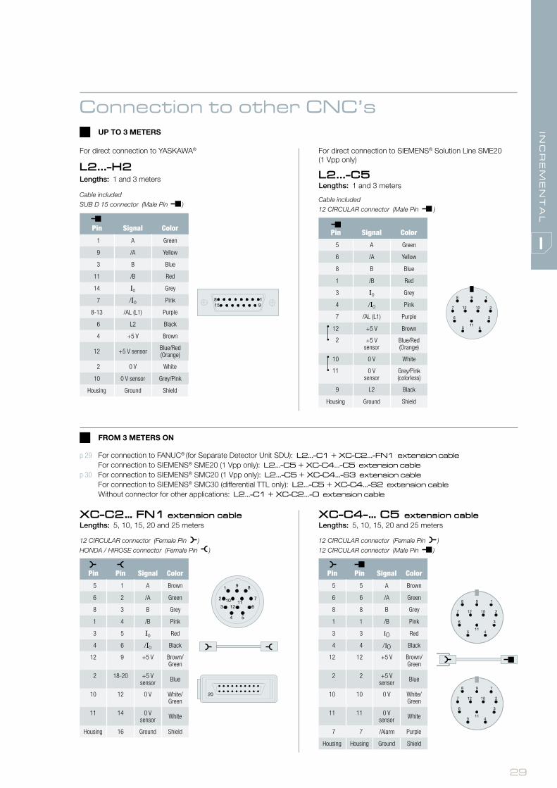
Connection to other CNC’s
Connector for direct connection to PANASONIC® MINAS A5
L2AP-PN5Lengths: 1 and 3 meters
Cable included
10-pin MOLEX/3M RECTANGULAR connector (Female Pin )
Connector for direct connection to YASKAWA®
L2AK-PNLengths: 1 and 3 meters
Cable included
6-pin MOLEX connector (Female Pin )
UP TO 3 METERS
FROM 3 METERS ON
XC-C8-...A-PN5 extension cableLengths: 5, 10, 15, 20 and 25 meters
CIRCULAR 17 connector (Female Pin )
PANASONIC 10 pin connector (Female Pin )
XC-C8-...-PN extension cableLengths: 5, 10, 15, 20 and 25 meters
CIRCULAR 17 connector (Female Pin )
PANASONIC 6 pin connector (Female Pin )
Connector for direct connection to MITSUBISHI®
L2AM-MB / L2AM2-MBLengths: 1 and 3 meters
Cable included
10-pin MOLEX/3M RECTANGULAR connector (Female Pin )
XC-C8… MB extension cableLengths: 5, 10, 15, 20 and 25 meters
CIRCULAR 17 connector (female Pin )
10-pin MOLEX/3M RECTANGULAR connector (female Pin )
Pin Pin Signal Color
8 7 SD (MD) Purple
9 8 /SD (MD) Yellow
14 3 RQ (MR) Grey
17 4 /RQ (MR) Pink
7 1 +5 V Brown/Green
1 – +5 V sensor Blue
10 2 GND White/Green
4 – 0 Vsensor White
Housing Housing Ground Shield
For connection to MITSUBISHI® full duplex: L2AM...-C9D + XC-C8-MB extension cableFor connection to MITSUBISHI® half duplex: L2AM2...-C9D + XC-C8-MB extension cableFor connection to PANASONIC®: L2AP...-C9D + XC-C8...A-PN5 extension cableFor connection to YASKAWA®: L2AK...-C9D + XC-C8-PN extension cable
(*) : only used in full duplex model L2AM-MB
Pin Signal
7 SD (MD) (*)
8 /SD (MD) (*)
3 RQ (MR)
4 /RQ (MR)
1 +5 V
2 0 V
Housing Ground
18
1
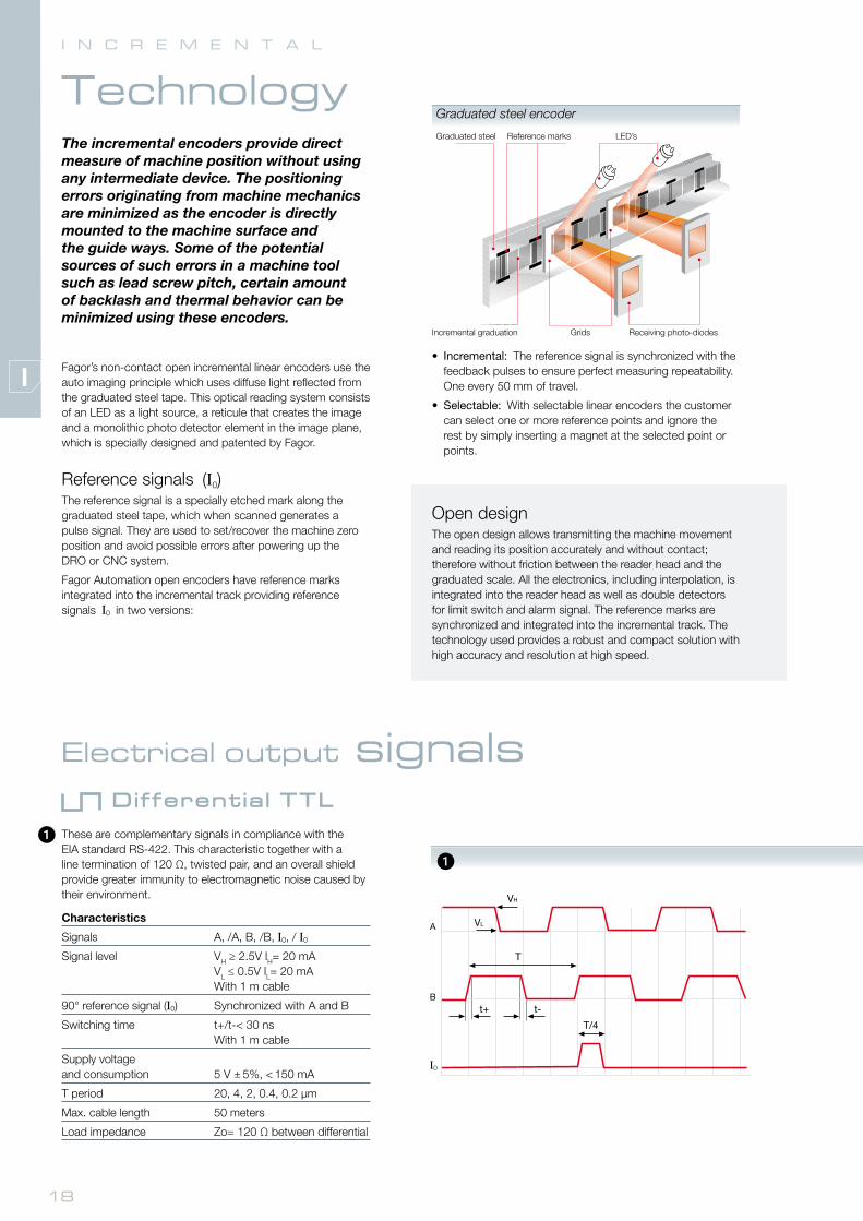
I N C R E M E N T A L
Fagor’s non-contact open incremental linear encoders use the auto imaging principle which uses diffuse light reflected from the graduated steel tape. This optical reading system consists of an LED as a light source, a reticule that creates the image and a monolithic photo detector element in the image plane, which is specially designed and patented by Fagor.
Reference signals (I0)The reference signal is a specially etched mark along the graduated steel tape, which when scanned generates a pulse signal. They are used to set/recover the machine zero position and avoid possible errors after powering up the DRO or CNC system.
Fagor Automation open encoders have reference marks integrated into the incremental track providing reference signals I0 in two versions:
The incremental encoders provide direct measure of machine position without using any intermediate device. The positioning errors originating from machine mechanics are minimized as the encoder is directly mounted to the machine surface and the guide ways. Some of the potential sources of such errors in a machine tool such as lead screw pitch, certain amount of backlash and thermal behavior can be minimized using these encoders.
Technology
Electrical output signals
These are complementary signals in compliance with the EIA standard RS-422. This characteristic together with a line termination of 120 Ω, twisted pair, and an overall shield provide greater immunity to electromagnetic noise caused by their environment.
Characteristics
Signals A, /A, B, /B, I0, / I0
Signal level VH ≥ 2.5V IH= 20 mA VL ≤ 0.5V IL= 20 mA With 1 m cable
90° reference signal (I0) Synchronized with A and B
Switching time t+/t-< 30 ns With 1 m cable
Supply voltage and consumption 5 V ± 5%, < 150 mA
T period 20, 4, 2, 0.4, 0.2 µm
Max. cable length 50 meters
Load impedance Zo= 120 Ω between differential
Different ia l TTL
• Incremental: The reference signal is synchronized with the feedback pulses to ensure perfect measuring repeatability.One every 50 mm of travel.
• Selectable: With selectable linear encoders the customer can select one or more reference points and ignore the rest by simply inserting a magnet at the selected point or points.
Open designThe open design allows transmitting the machine movement and reading its position accurately and without contact; therefore without friction between the reader head and the graduated scale. All the electronics, including interpolation, is integrated into the reader head as well as double detectors for limit switch and alarm signal. The reference marks are synchronized and integrated into the incremental track. The technology used provides a robust and compact solution with high accuracy and resolution at high speed.
1
Graduated steel
Grids
LED’s
Incremental graduation
Reference marks
Receiving photo-diodes
Graduated steel encoder

19
4
5
3
2
Electrical output signals
Voltage drop across cableThe voltage required for a TTL encoder must be 5V ± 5%. A simple formula may be used to calculate the maximum cable length depending on the section of the supply cables.
Lmax = (VCC-4.75)* 500 / (ZCABLE/Km* IMAX)
Example
Vcc = 5V, IMAX = 0.1 Amp
Z (1 mm2) = 16.6 Ω/Km (Lmax= 75 m)
Z (0.5 mm2) = 32 Ω/Km (Lmax= 39 m)
Z (0.25 mm2) = 66 Ω/Km (Lmax=19 m)
Z (0.14 mm2) = 132 Ω/Km (Lmax= 9 m)
Z (0.09 mm2) = 232 Ω/Km (Lmax= 5 m)
(encoder)Vpp
They are complementary sinusoidal signals whose differential value is 1 Vpp centered on Vcc/2. This characteristic together with a line termination of 120 Ω, twisted pair, and an overall shield provide greater immunity to electromagnetic noise caused by their environment.
Characteristics
Signals A, /A, B, /B, I0, / I0
VApp 1 V +20%, -40%
VBpp 1 V +20%, -40%
DC offset 2.5 V ± 0.5 V
Signal period 20 µm, 40 µm
Supply V 5 V ± 10%, < 150 mA
Max. cable length 150 meters
A, B centered: |V1-V2| / 2 Vpp ≤ 0.065
A&B relationship: VApp / VBpp 0.8 ÷ 1.25
A&B phase shift: 90° ± 10°
I0 amplitude: VI0 0.2 ÷ 0.8 V
I0 width: L + R I0_min: 180° I0_typ: 360° I0_max: 540°
I0 synchronism: L, R 180° ± 90°
Voltage drop across cableThe voltage required for a 1 Vpp encoder must be 5 V ± 10%. A simple formula may be used to calculate the maximum cable length depending on the section of the supply cables:
Lmax = (VCC-4.5)* 500 / (ZCABLE/Km* IMAX)
Example
Vcc = 5V, IMAX= 0.1Amp
Z (1 mm2) = 16.6 Ω/Km (Lmax= 150 m)
Z (0.5 mm2) = 32 Ω/Km (Lmax= 78 m)
Z (0.25 mm2) = 66 Ω/Km (Lmax= 37 m)
Z (0.14 mm2) = 132 Ω/ Km (Lmax= 18 m)
Z (0.09 mm2) = 232 Ω/ Km (Lmax= 10 m)
Different ia l 1 Vpp
1 Vpp signal damping due to the cable sectionBesides attenuation due to signal frequency, there is another signal attenuation caused by the section of the cable connected to the encoder.
4
5
2
3
meters
Cable length
(encoder)
meters
Vcc
0.8
1 V
0.6
0.4
0.2
0.0
0.09 mm2
0.14 mm2
L R
T=360...
Vpp
Vpp
V I0
V1
V2
I0 min
I0 max
(encoder)
meters
Cable length
Vcc
Cable length
4.9
5 V
4.8
4.7
4.6
4.5
4.9
5 V
4.8
4.7
4.6
4.5

20
I N C R E M E N T A L
Range
Analyze the application to make sure that the proper encoder will be selected for the machine.To do this, bear in mind the following considerations:
InstallationConsider the physical length of the installation and the space available for it.These aspects are crucial to determine the type of linear encoder to use.
Mechanical Design:EXA: adhesive model with the smallest cross section for constraint spaces, it consists of an engraved steel tape glued directly onto the machine surface, recommended if the tape is under thermally stable conditions.
EXG: guided model for long measuring lengths it comprises an aluminium extrusion glued to the surface and an engraved steel tape. The steel tape is guided in the extrusion and secured in the mid point to the machine surface that allows the tape to expand/contract freely at its ends and ensures a defined thermal behaviour.
EXT: tensioned model for very long measuring lengths and high accuracy it comprises an aluminium extrusion glued or screwed to the surface, an engraved steel tape and tensioning system. The steel tape is guided in the extrusion and tensioned between its ends. The tensioned steel tape is fixed on the machine base so it replicates the thermal behaviour of the surface.
AccuracyEach linear encoder is subjected to quality control showing its accuracy along its measuring length.
SignalConsider the following variables for selecting the type of signal: resolution, cable length and compatibility.
ResolutionThe resolution of the control of machine depends on the linear encoder.
Cable lengthThe length of the cable depends on the type of signal.
SpeedThe speed requirements for the application must be analyzed before choosing the linear encoder.
Shock and VibrationFagor linear encoders withstand vibrations of up to 200 m/s2 and shocks of up to 1000 m/s2.
Alarm signalAll TTL and 1 Vpp models offer an alarm signal.
Series SectionMeasuring lengths
Accuracy SignalsPitchResolution up to
Model
incremental EXA
Adhesive
70 mm up to 16 020 mm
± 10 µm/m
1 Vpp 0.1 µm TA + L2RP / L2SP
TTL 5 µm TA + L2RD / L2SD
TTL 1 µm TA+ L2RX / L2SX
TTL 0.5 µm TA + L2RY / L2SY
TTL 0.1 µm TA + L2RW / L2SW
TTL 0.1 µm TA + L2RW1/L2SW1
incremental EXG
Guided
240 mm up to 6 040 mm
± 10 µm/m
1 Vpp 0.1 µm PG + TG + L2RP / L2SP
TTL 5 µm PG + TG + L2RD / L2SD
TTL 1 µm PG + TG + L2RX / L2SX
TTL 0.5 µm PG + TG + L2RY / L2SY
TTL 0.1 µm PG + TG + L2RW / L2SW
TTL 0.1 µm PG + TG + L2RW1/L2SW1
incremental EXT
Tensioned
140 mm up to 30 040 mm
± 5 µm/m
1 Vpp 0.1 µm PT + TT + L2RP / L2SP
TTL 5 µm PT + TT + L2RD / L2SD
TTL 1 µm PT + TT + L2RX / L2SX
TTL 0.5 µm PT + TT + L2RY / L2SY
TTL 0.1 µm PT + TT + L2RW / L2SW
TTL 0.1 µm PT + TT + L2RW1/L2SW1

21
Series SectionMeasuring lengths
Accuracy SignalsPitchResolution up to
Model
incremental EXA
Adhesive
70 mm up to 16 020 mm
± 10 µm/m
1 Vpp 0.1 µm TA + L2RP / L2SP
TTL 5 µm TA + L2RD / L2SD
TTL 1 µm TA+ L2RX / L2SX
TTL 0.5 µm TA + L2RY / L2SY
TTL 0.1 µm TA + L2RW / L2SW
TTL 0.1 µm TA + L2RW1/L2SW1
incremental EXG
Guided
240 mm up to 6 040 mm
± 10 µm/m
1 Vpp 0.1 µm PG + TG + L2RP / L2SP
TTL 5 µm PG + TG + L2RD / L2SD
TTL 1 µm PG + TG + L2RX / L2SX
TTL 0.5 µm PG + TG + L2RY / L2SY
TTL 0.1 µm PG + TG + L2RW / L2SW
TTL 0.1 µm PG + TG + L2RW1/L2SW1
incremental EXT
Tensioned
140 mm up to 30 040 mm
± 5 µm/m
1 Vpp 0.1 µm PT + TT + L2RP / L2SP
TTL 5 µm PT + TT + L2RD / L2SD
TTL 1 µm PT + TT + L2RX / L2SX
TTL 0.5 µm PT + TT + L2RY / L2SY
TTL 0.1 µm PT + TT + L2RW / L2SW
TTL 0.1 µm PT + TT + L2RW1/L2SW1

22
Non-contact open linear encoder for high accuracy, high speed applications.
It consists of a compact reader head with all the electronics and optics integrated into a single body that may be mounted from the side or from the top.
It has an LED to help mounting it and includes a 1 or 3 meter cable with a connector, a 6 mm wide adhesive reflective stainless steel tape that is highly resistant to solvents and reference signal synchronized on line.
Measuring lengths in millimeters
Available from 70 mm to 16,020 mm in 50 mm increments.
Model description
TA + L2R: non-contact open linear connector with an incremental reader head, incremental I0 (every 50 mm) and an adhesive incremental tape.
TA + L2S: non-contact open linear connector with an incremental reader head, I0 that may be selected with a magnet and an adhesive incremental tape.
Characteristics
TA + L2RD TA + L2RX TA + L2RY TA + L2RW TA + L2RW1 TA + L2RP
Measurement Incremental: By means of a 20 µm-pitch graduated steel tape
Steel thermal expansion coefficient αtherm: ≈ 11 ppm/K.
Measuring resolution 5 µm 1 µm 0.5 µm 0.1 µm 0.1 µm Up to 0.1 µm
Output signals TTL differential TTL differential TTL differential TTL differential TTL differential 1 Vpp
Incremental signal period 20 µm 4 µm 2 µm 0.4 µm 0.4 µm 20 µm
Limit frequency 200 kHz 1 MHz 1 Mhz 1.5 Mhz 2.5 Mhz 400 Khz
Maximum speed 240 m/min 240 m/min 120 m/min 36 m/min 60 m/min 480 m/min
Minimum distance between flanks 1.2 µs 0.2 µs 0.2 µs 0.2 µs 0.05 µs –
Reference marks I0L2RD, L2RX, L2RY, L2RW, L2RW1, L2RP: every 50 mmL2SD, L2SX, L2SY, L2SW, L2SW1, L2SP: I0 that may be selected with a magnet
Limits Open collector, active low. Activation by magnets
Maximum cable length 50 m 50 m 50 m 50 m 50 m 150 m
Supply voltage 5V ±5%, < 150 mA (without load)
5V ±5%, < 150 mA (without load)
5V ±5%, < 150 mA (without load)
5V ±5%, < 150 mA (without load)
5V ±5%, < 150 mA (without load)
5V ±10%, < 150 mA (without load)
Reader head 1 or 3 meter cable with a connector
Reader head protection IP 40
Accuracy ± 10 µm/m
Maximum vibration 200 m/s2 (55 … 2000 Hz) IEC 60068-2-6
Maximum shock 1000 m/s2 (11 ms) IEC 60068-2-27
Operating temperature 0°C … 50°C
Storage temperature -20°C ... 70°C
Weight 0.17 kg + 0.025 kg/m
Relative humidity 20 … 80%
I N C R E M E N T A L
EXA seriesA D H E S I V E

23
INC
RE
ME
NT
AL
Dimensions in mm
Reader head
L2 R X 3 C1Single-body reader head with LED
Type of reference mark I0:
R: incremental every 50 mm S: may be selected with a magnet
Type of signal:
D: 5 µm resolution differential TTLX: 1 µm resolution differential TTLY: 0. 5 µm resolution differential TTLW/W1: 0.1 µm resolution differential TTLP: 1 Vpp sinusoidal
Cable length:
1: 1 meter3: 3 meters
Connector:
D: Sub D HD 15 MH2: YASKAWA®
C1: M-F threaded 12-pin round connectorC5: M-M threaded 12-pin round connector
Order identif ication
Example of Non-contact linear Encoder: TA-62 + L2RX-3C1
Tape
TA 62Incremental graduated tape for the adhesive model Measuring lengths in centimeters:
In the example 62 = 620 mm
I0 / Reference marks

24
Non-contact open linear encoder for high accuracy, high speed applications.
It consists of a compact reader head with all the electronics and optics integrated into a single body that may be mounted from the side or from the top.
It has an LED to help mounting it and includes a 1 or 3 meter cable with a connector, a 10 mm wide reflective stainless steel tape that is highly resistant to solvents on an adhesive aluminum guide.
Measuring lengths in millimeters
Available from 240 mm to 6,040 mm in 100 mm increments.
Model description
PG + TG + L2R: non-contact open linear connector with an incremental reader head, incremental I0 (every 50 mm) and an incremental tape with an aluminum adhesive guide.
PG + TG + L2S: non-contact open linear connector with an incremental reader head, I0 that may be selected with a magnet and an incremental tape with an aluminum adhesive guide.
I N C R E M E N T A L
EXG seriesG U I D E D
Characteristics
PG + TG + L2RD
PG + TG + L2RX
PG + TG + L2RY
PG + TG + L2RW
PG + TG + L2RW1
PG + TG + L2RP
Measurement Incremental: By means of a 20 µm-pitch graduated steel tape
Steel thermal expansion coefficient αtherm: ≈ 11 ppm/K.
Measuring resolution 5 µm 1 µm 0.5 µm 0.1 µm 0.1 µm Up to 0.1 µm
Output signals TTL differential TTL differential TTL differential TTL differential TTL differential 1 Vpp
Incremental signal period 20 µm 4 µm 2 µm 0.4 µm 0.4 µm 20 µm
Limit frequency 200 kHz 1 MHz 1 Mhz 1.5 Mhz 2.5 Mhz 400 Khz
Maximum speed 240 m/min 240 m/min 120 m/min 36 m/min 60 m/min 480 m/min
Minimum distance between flanks 1.2 µs 0.2 µs 0.2 µs 0.2 µs 0.05 µs –
Reference marks I0L2RD, L2RX, L2RY, L2RW, L2RW1, L2RP: every 50 mmL2SD, L2SX, L2SY, L2SW, L2SW1, L2SP: I0 that may be selected with a magnet
Limits Open collector, active low. Activation by magnets
Maximum cable length 50 m 50 m 50 m 50 m 50 m 150 m
Supply voltage 5V ±5%, < 150 mA (without load)
5V ±5%, < 150 mA (without load)
5V ±5%, < 150 mA (without load)
5V ±5%, < 150 mA (without load)
5V ±5%, < 150 mA (without load)
5V ±10%, < 150 mA (without load)
Reader head 1 or 3 meter cable with a connector
Reader head protection IP 40
Accuracy ± 10 µm/m
Maximum vibration 200 m/s2 (55 … 2000 Hz) IEC 60068-2-6
Maximum shock 1000 m/s2 (11 ms) IEC 60068-2-27
Operating temperature 0°C … 50°C
Storage temperature -20°C ... 70°C
Weight 0.27 kg + 0.05 kg/m
Relative humidity 20 … 80%

25
INC
RE
ME
NT
AL
Dimensions in mm
Order identif ication
Example of Non-contact linear Encoder: PG30 + TG-64 + L2RX-3C1
Guide Tape
PG 30 TG 64Adhesive guide for guided tape Lengths in centimeters:
In the example 30 = 300 mm
Incremental graduated tape for the guided model
Measuring lengths in centimeters:
In the example 64 = 640 mm
Reader head
L2 R X 3 C1Single-body reader head with LED
Type of reference mark I0:
R: incremental every 50 mm S: may be selected with a magnet
Type of signal:
D: 5 µm resolution differential TTLX: 1 µm resolution differential TTLY: 0.5 µm resolution differential TTLW/W1: 0.1 µm resolution differential TTLP: 1 Vpp sinusoidal
Cable length:
1: 1 meter3: 3 meters
Connector:
D: Sub D HD 15 MH2: YASKAWA®
C1: M-F threaded 12-pin round connectorC5: M-M threaded 12-pin round connector
I0 / Reference
marks

26
I N C R E M E N T A L
EXT series
Non-contact open linear encoder for high accuracy, high speed applications.
It consists of a compact reader head with all the electronics and optics integrated into a single body that may be mounted from the side or from the top.
It has an LED to help mounting it and includes a 1 or 3 meter cable with a connector, a 10 mm wide reflective stainless steel tape that is highly resistant to solvents on an adhesive or bolted aluminum guide.
T E N S I O N E D
Measuring lengths in millimeters
Available from 140 mm to 30,040 mm in 100 mm increments.
Model description
PT + TT + L2R: non-contact open linear connector with an incremental reader head, incremental I0 (every 50 mm) and a tensioned incremental tape with an aluminum adhesive guide. Indicate PTS for bolted guided.
PT + TT + L2S: non-contact open linear connector with an incremental reader head, I0 that may be selected with a magnet and a tensioned incremental tape with an aluminum adhesive guide. Indicate PTS for bolted guided.
Characteristics
PT + TT + L2RD
PT + TT + L2RX
PT + TT + L2RY
PT + TT + L2RW
PT + TT + L2RW1
PT + TT + L2RP
Measurement Incremental: By means of a 20 µm-pitch graduated steel tape
Steel thermal expansion coefficient αtherm: ≈ 11 ppm/K.
Measuring resolution 5 µm 1 µm 0.5 µm 0.1 µm 0.1 µm Up to 0.1 µm
Output signals TTL differential TTL differential TTL differential TTL differential TTL differential 1 Vpp
Incremental signal period 20 µm 4 µm 2 µm 0.4 µm 0.4 µm 20 µm
Limit frequency 200 kHz 1 MHz 1 Mhz 1.5 Mhz 2.5 Mhz 400 Khz
Maximum speed 240 m/min 240 m/min 120 m/min 36 m/min 60 m/min 480 m/min
Minimum distance between flanks 1.2 µs 0.2 µs 0.2 µs 0.2 µs 0.05 µs –
Reference marks I0L2RD, L2RX, L2RY, L2RW, L2RW1, L2RP: every 50 mmL2SD, L2SX, L2SY, L2SW, L2SW1, L2SP: I0 that may be selected with a magnet
Limits Open collector, active low. Activation by magnets
Maximum cable length 50 m 50 m 50 m 50 m 50 m 150 m
Supply voltage 5V ±5%, < 150 mA (without load)
5V ±5%, < 150 mA (without load)
5V ±5%, < 150 mA (without load)
5V ±5%, < 150 mA (without load)
5V ±5%, < 150 mA (without load)
5V ±10%, < 150 mA (without load)
Reader head 1 or 3 meter cable with a connector
Reader head protection IP 40
Accuracy ± 5 µm /m
Maximum vibration 200 m/s2 (55 … 2000 Hz) IEC 60068-2-6
Maximum shock 1000 m/s2 (11 ms) IEC 60068-2-27
Operating temperature 0°C … 50°C
Storage temperature -20°C ... 70°C
Weight 0.27 kg + 0.26 kg/m
Relative humidity 20 … 80%

27
INC
RE
ME
NT
AL
Dimensions in mm
Order identif ication
Example of Non-contact linear Encoder: PT70 + TT-62 + L2RX-3C1
Guide Tape
PT 70 TT 64PT: adhesive guide for tensioned tape
PTS: bolted guide for tensioned tape
Lengths in centimeters -1:
In the example 70 = 699 mm
Incremental graduated tape for the tensioned model
Measuring lengths in centimeters:
In the example 64 = 640 mm
Reader head
L2 R X 3 C1Single-body reader head with LED
Type of reference mark I0:
R: incremental every 50 mm S: may be selected with a magnet
Type of signal:
D: 5 µm resolution differential TTLX: 1 µm resolution differential TTLY: 0.5 µm resolution differential TTLW/W1: 0.1 µm resolution differential TTLP: 1 Vpp sinusoidal
Cable length:
1: 1 meter3: 3 meters
Connector:
D: Sub D HD 15 MH2: YASKAWA®
C1: M-F threaded 12-pin round connectorC5: M-M threaded 12-pin round connector
I0 / Reference marks

28
Pin Signal Color
1 A Green
2 /A Yellow
3 B Blue
4 /B Red
5 I0 Grey
6 /I0 Pink
7 L2 Black
8 /AL (L1) Purple
9 +5 V Brown
10 +5 V sensor
Blue/Red (Orange)
11 0 V White
12 0 V sensor
Grey/Pink (colorless)
Housing Ground Shield
Pin Signal Color
5 A Green
6 /A Yellow
8 B Blue
1 /B Red
3 I0 Grey
4 /I0 Pink
7 /AL (L1) Purple
12 +5 V Brown
2 +5 V sensor
Blue/Red (Orange)
10 0 V White
11 0 V sensor
Grey/Pink (colorless)
9 L2 Black
Housing Ground Shield
UP TO 3 METERS
FROM 3 METERS ON
I N C R E M E N T A L
direct connection cables
For direct connection to FAGOR
L2...-DLengths: 1 and 3 meters
Cable included
SUB D 15 HD connector (Male Pin )
L2...-C1 + XC-C2-...D extension cableLengths: 1 and 3 meters
Cable included
12 CIRCULAR connector (Male Pin )
Pin Pin Signal Color
5 1 A Brown
6 2 /A Green
8 3 B Grey
1 4 /B Pink
3 5 I0 Red
4 6 /I0 Black
7 8 /AL (L1) Purple
9 7 L2 Yellow
12 9 5 V Brown/Green
2 9 +5 V sensor Blue
10 11 0 V White/Green
11 11 0 V sensor White
Housing Housing Ground Shield
XC-C2-...D extension cableLengths: 5, 10, 15, 20 and 25 meters
12 CIRCULAR connector (Female Pin )
SUB D 15 HD connector (Male Pin )
Connection to FAGOR CNC
29
INC
RE
ME
NT
AL
For direct connection to YASKAWA®
L2...-H2Lengths: 1 and 3 meters
Cable included
SUB D 15 connector (Male Pin )
Connection to other CNC’sUP TO 3 METERS
Pin Signal Color
1 A Green
9 /A Yellow
3 B Blue
11 /B Red
14 I0 Grey
7 /I0 Pink
8-13 /AL (L1) Purple
6 L2 Black
4 +5 V Brown
12 +5 V sensor Blue/Red (Orange)
2 0 V White
10 0 V sensor Grey/Pink
Housing Ground Shield
Pin Signal Color
5 A Green
6 /A Yellow
8 B Blue
1 /B Red
3 I0 Grey
4 /I0 Pink
7 /AL (L1) Purple
12 +5 V Brown
2 +5 V sensor
Blue/Red (Orange)
10 0 V White
11 0 V sensor
Grey/Pink (colorless)
9 L2 Black
Housing Ground Shield
For direct connection to SIEMENS® Solution Line SME20 (1 Vpp only)
L2...-C5Lengths: 1 and 3 meters
Cable included
12 CIRCULAR connector (Male Pin )
FROM 3 METERS ON
Pin Pin Signal Color
5 1 A Brown
6 2 /A Green
8 3 B Grey
1 4 /B Pink
3 5 I0 Red
4 6 /I0 Black
12 9 +5 V Brown/Green
2 18-20 +5 V sensor Blue
10 12 0 V White/Green
11 14 0 V sensor White
Housing 16 Ground Shield
XC-C2… FN1 extension cableLengths: 5, 10, 15, 20 and 25 meters
12 CIRCULAR connector (Female Pin )
HONDA / HIROSE connector (Female Pin )
Pin Pin Signal Color
5 5 A Brown
6 6 /A Green
8 8 B Grey
1 1 /B Pink
3 3 I0 Red
4 4 /I0 Black
12 12 +5 V Brown/Green
2 2 +5 V sensor Blue
10 10 0 V White/Green
11 11 0 V sensor White
7 7 /Alarm Purple
Housing Housing Ground Shield
XC-C4-… C5 extension cableLengths: 5, 10, 15, 20 and 25 meters
12 CIRCULAR connector (Female Pin )
12 CIRCULAR connector (Male Pin )
p 29 For connection to FANUC® (for Separate Detector Unit SDU): L2...-C1 + XC-C2...-FN1 extension cable For connection to SIEMENS® SME20 (1 Vpp only): L2...-C5 + XC-C4...-C5 extension cablep 30 For connection to SIEMENS® SMC20 (1 Vpp only): L2...-C5 + XC-C4...-S3 extension cable For connection to SIEMENS® SMC30 (differential TTL only): L2...-C5 + XC-C4...-S2 extension cable Without connector for other applications: L2...-C1 + XC-C2...-O extension cable

30
I N C R E M E N T A L
direct connection cables
Pin Signal Color
5 A Brown
6 /A Green
8 B Grey
1 /B Pink
3 I0 Red
4 /I0 Black
7 /AL (L1) Purple
9 L2 Yellow
12 +5 V Brown/Green
2 +5 V sensor Blue
10 0 V White/Green
11 0 V sensor White
Housing Ground Shield
XC-C2...O extension cableLengths: 5, 10, 15, 20 and 25 meters
12 CIRCULAR connector (Female Pin )
Pin Pin Signal Color
5 3 A Brown
6 4 /A Green
8 6 B Grey
1 7 /B Pink
3 17 I0 Red
4 18 /I0 Black
12 1 +5 V Brown/Green
2 14 +5 V sensor Blue
10 2 0 V White/Green
11 16 0 V sensor White
Housing Housing Ground Shield
XC-C4-… S3 extension cableLengths: 5, 10, 15, 20 and 25 meters
12 CIRCULAR connector (female Pin )
SUB D25 connector (female Pin )
Pin Pin Signal Color
5 15 A Brown
6 14 /A Green
8 13 B Grey
1 12 /B Pink
3 10 I0 Red
4 11 /I0 Black
12 4 +5 V Brown/Green
5 +5 V
2 6 +5 V sensor Blue
10 2 0 V White/Green
11 16 0 V sensor White
Housing Housing Ground Shield
XC-C4-… S2 extension cableLengths: 5, 10, 15, 20 and 25 meters
12 CIRCULAR connector (female Pin )
SUB D15 connector (Male Pin )

31
INC
RE
ME
NT
AL
MagnetsMagnetic actuators are used to activate the limit switches, and to select the reference-marks.
The magnetic actuators can have either a metal or plastic housing.
– Adhesive or screw on metal housing.
I N C R E M E N T A L E N C O D E R S
accessories
AA or AAA applierThe applier is used to stick the adhesive tape onto the machine surface for proper alignment with the reader head.
SSDThe external device to measure signal strength is used for mounting and aligning the read head correctly.
It has LEDs to help mounting it for the incremental signals, for the reference mark and for the limit switches.
Encoder and signalArrow color Description a b c
Adhesive, limit 1 Red MA-L1
25 9 8Adhesive, limit 2 Blue MA-L2
Adhesive, reference Grey MA-R
Guided, limit 1 Red MG-L1
25 9 9.5Guided, limit 2 Blue MG-L2
Guided, reference Grey MG-R
Tensioned, limit 1 Red MT-L1
25 9 12Tensioned, limit 2 Blue MT-L2
Tensioned, reference Grey MT-R
Encoder and signalArrow color Descripción a b c
Adhesive and guided, limit 1
Red MAG-L1
30 6.5 2.7Adhesive and guided, limit 2
Blue MAG-L2
Adhesive and guided, reference
Grey MAG-R
– Adhesive plastic housing.
c
b
a
a
c
b
14
3.5

ER-073/1994
worldwide automation
ATHENS
BARCELONA
BJERRING BRO
BUCHAREST
BUDAPEST
CLERMONT FERRAND
GOMEL
GÖPPINGEN
GÖTEBORG
ISTANBUL
IZEGEM
KAPELLEN
KOTLIN
LANGENTHAL
LOG PRI BREZOVICI
MILANO
MOSKVA
NEUCHATEL
NORTHAMPTON
PORTO
PARDUBICE
ROOSENDAAL
THESSALONIKI
TOIJALA
TROYAN
UTRECHT
WIENER NEUDORF
WUPPERTAL
USURBILESKORIATZABEIJING
MONDRAGÓN
AUCKLAND
DUNEDIN
MELBOURNE
SYDNEY
BOGOTÁ
BUENOS AIRES
CHICAGO
DALLAS
EL SALVADOR D.F.
LIMA
LOS ANGELES
MEXICO D.F.
MONTERREY N.L.
MONTEVIDEO
MONTREAL
NEW JERSEY
SANTIAGO
SAO PAULO
TAMPA
TORONTO
JOHANNESBURG
BANGALORE
BANGKOK
DELHI
GUANGZHOU
HO CHI MINH CITY
HONG KONG
JAKARTA
KUALA LUMPUR
MANILA
NANJING
PUNE
RAJKOT
SHANGHAI
SHARJAH
SEOUL
SINGAPORE
TAICHUNG
TEL-AVIV
TOKYO
EP
S -
EXP
OS
ED
E
N 0
717
DRIVE-CLiQ® is a registered trademark of SIEMENS® Aktiengesellschaft, FeeDat® is a registered trademark of Fagor Automation, FANUC® is a registered trademark of FANUC® Ltd. MITSUBISHI® is a registered trademark of MITSUBISHI® Shoji Kaisha, Ltd., PANASONIC® is a registered trademark of PANASONIC® Corporation,BiSS® is a registered trademark of iC-Haus GmbH, andYASKAWA® is a registered trademark of YASKAWA® Electric Corporation.
Fagor Automation shall not be held responsible for any printing or transcribing errors in the catalog and reserves the right to make any changes to the characteristics of its products without prior notice. You must always compare the data with that appearing in the manual that comes with the product.
Fagor Automation holds the ISO 9001 Quality System Certificate and the
Certificate for all products manufactured.
subsidiary dist r ibutor
america
africa
europe
asia
oceania
HeadquartersPlants
Fagor Automation, S. Coop.Bº San Andrés, 19E-20500 Arrasate - MondragónSPAINTel.: +34 943 039 800Fax: +34 943 791 712E-mail: [email protected]
www.fagorautomat ion.com