![Olo¸`M{ XqS ` M{ »^t ¯bÆ...\ O ^ X O]V h `sU T_ mZoçM\O{ hT^ DN Þ ç|Ø»ïçsr SxsçMlzM hT^ DN M U sU^ DN \O^X O`|Þ ççsr xs¢±ª ¯é¯éY hT^ DN Öï|M U O` \ Ubqçr sç~Ot](https://static.fdocuments.net/doc/165x107/5e3a1173fd377216732a61c4/olom-xqs-m-t-b-o-x-ov-h-su-t-mzomo-ht-dn-sr.jpg)
Nominal Diameter: Nominal Pressure: Temperature Range ... · DN 50: Ç=1,4; Kv=85 DN 200: Ç=0.8;...
36
Application: Исполнение: fully welded / полностью сварной two and three piece design модель из 2-х или 3-х частей Nominal Diameter: Условный диаметр DN 3 - 900 mm / 1/8 up to 36 inches (bigger diameters on request) (Больший диаметр по запросу) Nominal Pressure: Номинальное давление до PN 800 mm / ANSI Class 150 - 2500 Temperature Range: Температурный предел От -180°C до +650°C / от -292°F до +1200°F Range of Application Область применения • District heating pipeline systems трубопроводные системы централизованного теплоснабжения • Underground installations подземная установка • Cold embedding система охлаждения • Chamber installation комнатная установка • Vent and drain valves выпускной и спускной клапаны • Spot-drill ball valves ??? • Tie-in ball valves дополнительные (соединительные) краны • Utility connection вспомогательное соединение • Steam пар
Transcript of Nominal Diameter: Nominal Pressure: Temperature Range ... · DN 50: Ç=1,4; Kv=85 DN 200: Ç=0.8;...
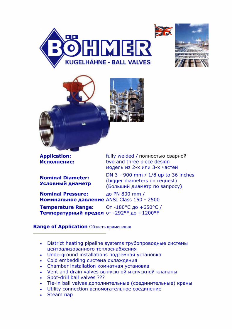
Application: Исполнение:
fully welded / полностью сварной two and three piece design модель из 2-х или 3-х частей
Nominal Diameter: Условный диаметр
DN 3 - 900 mm / 1/8 up to 36 inches (bigger diameters on request) (Больший диаметр по запросу)
Nominal Pressure: Номинальное давление
до PN 800 mm / ANSI Class 150 - 2500
Temperature Range: Температурный предел
От -180°C до +650°C / от -292°F до +1200°F
Range of Application Область применения
• District heating pipeline systems трубопроводные системы централизованного теплоснабжения
• Underground installations подземная установка • Cold embedding система охлаждения • Chamber installation комнатная установка • Vent and drain valves выпускной и спускной клапаны • Spot-drill ball valves ??? • Tie-in ball valves дополнительные (соединительные) краны • Utility connection вспомогательное соединение • Steam пар

Approvals Разрешения на эксплуатацию
• DIN EN ISO 9001
• GOST • DIN-DVGW • SVGW • AD-HP0
(TЬV)
• API 6D • Structural component approval Утверждённые элементы конструкции
• • ÖVGW • BAM
Technological approval/ welding: Проверка технологии и типа сварки:
• TRD 201 • DIN EN 729 • AD-HP 2/1 (TÜV)
Standard BÖHMER-District Heating Ball Valve Стандартный шаровой кран для централизованного теплоснабжения
• Structural component approved утверждённые элементы конструкции
• Fully welded design полностью сварная модель • Pressurable from both sides двухстороннее давление • Starting from DN 125, PN 16 trunnion mounted ball, начиная с DN
125, PN 16 шар, закреплённый в цапфе starting DN 65, PN 40 "Double Block and Bleed"- design начиная с DN 65, PN 40 модель “Двойной блок и спуск ”
• Compact design компактная модель • Long service life длительный период эксплуатации • Maintenance free ??? • Full and reduced bore полный и редуцированный проход • Body material made of forged steel (3.1.B material) Материал корпуса: кованная сталь
• Determination of the welding seams according to the valid rules for pipeline and pressure vessel production Конструкция из сварных швов в соответствии с правилами эксплуатации трубопровода и сосудов с давлением
• Low torque понижение крутящегося момента • Suitable for cold embedding/compensationless low depth underground
installation Подходящий для системы охлаждения/не компенсирующей с глубокой подземной установкой
• Higher resistance to corrosion than the pipeline system due to the more massive wall thickness of the ball valves Более высокая защита

от коррозии, чем у трубопроводных систем благодаря более массивной толщине стенок шарового крана
• Lowest temperature and pressure drops Самая низкая температура и перепады давления
• Thermal resistance of the sealing system термостойкость уплотнительной системы
• Chambered sealing system система камерного уплотнения • Self-adjusting sealing system in case of wear and tear Саморегулирующаяся уплотнительная система в случае износа и разрыва
• Replaceable sealing elements at the stem Взаимозаменяемые уплотнительные элементы в (устройстве)
• Variable plug-in system for stem extensions Система переменного подключения для ???
Standard BÖHMER-District Heating Ball Valve
• Structural component approved • Fully welded design • Pressurable from both sides • Starting from DN 125, PN 16 trunnion mounted ball,
starting DN 65, PN 40 "Double Block and Bleed"- design • Compact design • Long service life • Maintenance free • Full and reduced bore • Body material made of forged steel (3.1.B material) • Determination of the welding seams according to the valid rules for
pipeline and pressure vessel production • Low torque • Suitable for cold embedding/compensationless low depth underground
installation • Higher resistance to corrosion than the pipeline system due to the
more massive wall thickness of the ball valves • Lowest temperature and pressure drops • Thermal resistance of the sealing system • Chambered sealing system • Self-adjusting sealing system in case of wear and tear • Replaceable sealing elements at the stem • Variable plug-in system for stem extensions
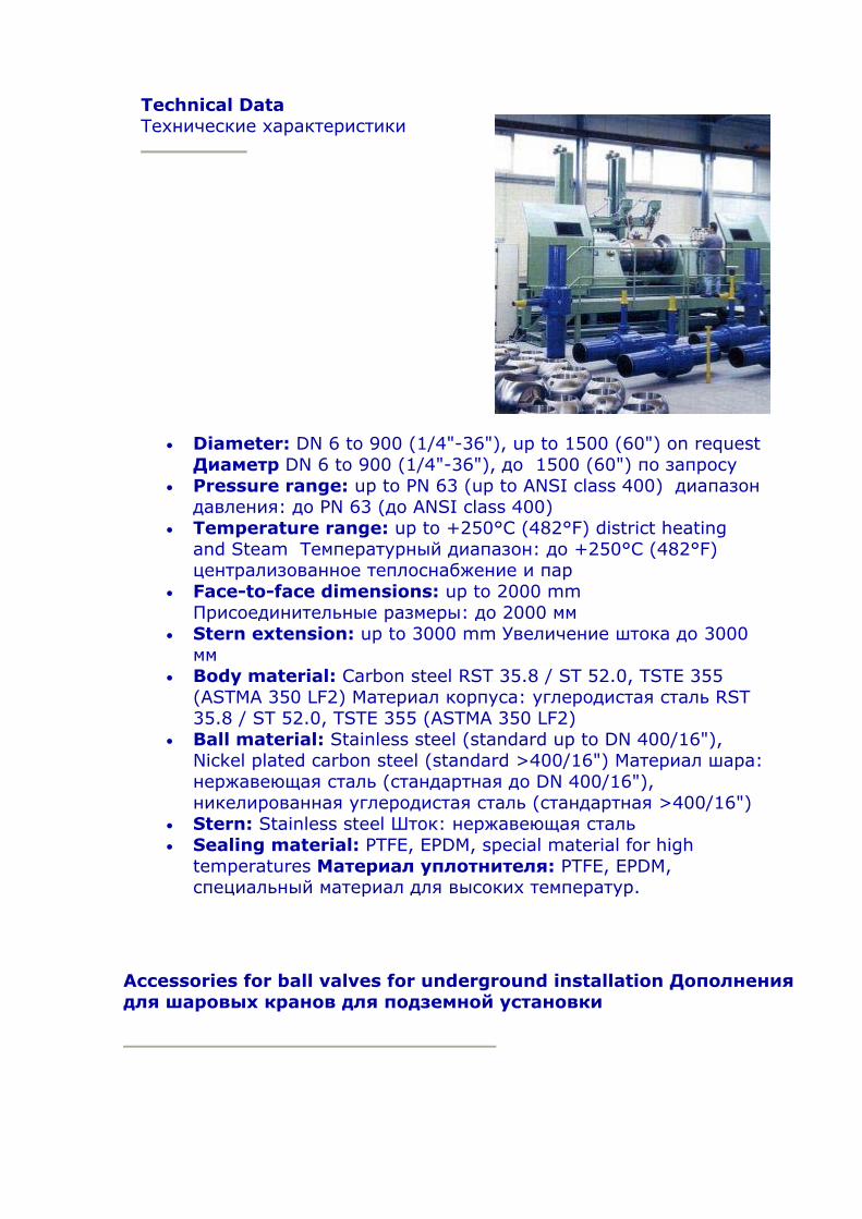
Technical Data Технические характеристики
• Diameter: DN 6 to 900 (1/4"-36"), up to 1500 (60") on request Диаметр DN 6 to 900 (1/4"-36"), до 1500 (60") по запросу
• Pressure range: up to PN 63 (up to ANSI class 400) диапазон давления: до PN 63 (до ANSI class 400)
• Temperature range: up to +250°C (482°F) district heating and Steam Температурный диапазон: до +250°C (482°F) централизованное теплоснабжение и пар
• Face-to-face dimensions: up to 2000 mm Присоединительные размеры: до 2000 мм
• Stern extension: up to 3000 mm Увеличение штока до 3000 мм
• Body material: Carbon steel RST 35.8 / ST 52.0, TSTE 355 (ASTMA 350 LF2) Материал корпуса: углеродистая сталь RST 35.8 / ST 52.0, TSTE 355 (ASTMA 350 LF2)
• Ball material: Stainless steel (standard up to DN 400/16"), Nickel plated carbon steel (standard >400/16") Материал шара: нержавеющая сталь (стандартная до DN 400/16"), никелированная углеродистая сталь (стандартная >400/16")
• Stern: Stainless steel Шток: нержавеющая сталь • Sealing material: PTFE, EPDM, special material for high
temperatures Материал уплотнителя: PTFE, EPDM, специальный материал для высоких температур.
Accessories for ball valves for underground installation Дополнения для шаровых кранов для подземной установки дДд
All dimensions deliverable tailor made. Все размеры могут подгоняться.
Tensile and Pressure Forces for Böhmer Ball Valves Эластичность и сила давления для шаровых кранов Böhmer
Diameter Pipeline Диаметр
трубопровода
Preheated pipeline (according EN 488)
Предварительно нагретый трубопровод (соответственно EN 488)
Cold embedded pipeline Система охлаждения
трубопровода
full bore DN
[mm] Полный проход
DN
reduced Bore
DN/LW [mm]
Редуци-рованный проход DN/LW
Tensile load at cool down by
70 K [kN] Растяги-
вающая Нагрузка
при охлаждении до 70 K
Pressure load at heating by
60 K [kN]
Сжимающая нагрузка при
нагревании до 60 K
Tensile load at cool down
by 130 K [kN]
Растяги-вающая нагрузка при
охлаждении до 130 K
Pressure load at heating by
130 K [kN]
Сжимающая нагрузка при
нагревании до 130 K
Permissible Tensile and pressure load Böhmer district heating ball valves [kN] Допустимая растягивающая и сжимающая нагрузка шаровых кранов Böhmer для централизованного теплоснабжения
20 25/20 32 29 31 62 95

25 32 40 50 65 80 100 125 150 200 250 300 350 400 500 600
32/25 40/32 50/40 65/50 80/65 100/80 125/100 150/125 200/150 250/200 300/250 400/300 400/350 500/400 600/500 700/600
40 64 74 94 120 140 204 251 337 495 686 913 1004 1291 1619 2192
37 57 65 83 106 124 180 222 297 437 606 806 887 1140 1430 1936
40 61 71 90 114 134 195 240 322 473 657 874 961 1235 1549 2098
79 123 141 179 229 269 391 480 644 947 1313 1747 1921 2471 3098 4198
120 155 180 200 240 290 420 520 700 1000 1400 2000 2350 2700 3300 4400
The values for preheated pipes given in the table are according to the values given in standard EN 488 expect for the values printed in bold letters that are according to the recommendations AGFW/FVGW-rule sheet FW 401 part 5 of 05 February 1999. Данные для предварительно нагретого трубопровода в таблице соответствуют данным в стандартном EN 488 положении данных, напечатанном в обозначенном документе в соответствии с рекомендациями AGFW/FVGW правил, ведомость FW 401, раздел 5 от 5 февраля 1999г.
The values for cold embedded pipelines have been taken from AGFW/FVGW-rule sheet FW 401 part 5 of 05 Februar 1999. The standard EN 488 does not contain values for the case. Данные для системы охлаждения водопровода взяты из AGFW/FVGW правил, ведомость FW 401, раздел 5 от 5 февраля 1999г. Стандартное приложение EN 488 не содержит этих данных.
The permission tensile and pressure load for Böhmer ball valves are valid for all fuly welded standard ball valves. Ball valves for extreme loads are deliverable too. Разрешение на растягивающую и сжимающую нагрузку для шаровых кранов Böhmer действительно для всех стандартных полностью сварных шаровых кранов.
Drag Coefficient of Böhmer Ball Valves Коэффициент лобового сопротивления шаровых кранов Böhmer
full bore полный проход
reduced bore редуцированный проход
DN Kv Ç(-) DN/LW Kv Ç(-)

(m³/h) (m³/h) 10-16
20 25 32 40 50 65 80 100 125 150 200 250 300 350 400 500 600
25 52 83 119 203 334 603 978 1510 2558 4181 7983 135802091728897383196054293059
0,17 0,09 0,09 0,12 0,10 0,09 0,08 0,07 0,06 0,06 0,05 0,05 0,04 0,03 0,03 0,03 0,03 0,02
20/16 25/20 32/25 40/32 50/40 65/50 80/65 100/80125/100150/125200/150250/200300/250400/300400/350500/400600/500700/600
15 32 50 98 139 242 359 604 932 1411 2547 4228 5189 1096311517179812677138483
1,14 0,60 0,67 0,43 0,51 0,49 0,51 0,44 0,45 0,41 0,40 0,35 0,34 0,34 0,33 0,31 0,29 0,26
Ç: pressure drag coefficient [-] Давление коэффициента лобового сопротивления Kv: Volume flow [m³/h] Water (15°C) pressure drop 1 bar Объем потока [m³/h] Вода (15°C) паден6ие давления 1 bar DN: Nominal diameter [mm] Условный диаметр LW: Diameter inside [mm] Внутренний диаметр
For determination of the drag coefficient ball valves with the standard (solid) ball and standard dimensions were used. Для определения коэффициента лобового сопротивления были использованы шаровые краны со стандартным (цельным) шаром и стандартными размерами.
Hollow balls cause a further increase of the drag and therefore to higher drag coefficient values. To give a correct value trunnion mounted balls and floating balls have to be distinguished. Since the use of trunnion mounted balls depends among other things on the working pressure it is not possible to set general valid drag coefficients for hollow balls in dependence to the nominal diameter. Полые шары являются причиной для дальнейшего увеличения (тормоза???) и поэтому увеличивается значение коэффициента лобового сопротивления. Чтобы дать верное значение закреплённым в цапфе шарам и плавающим шарам необходимо быть точным. С тех пор, как использование закреплённых в цапфе шаров зависит, кроме всего прочего, от рабочего давления, невозможно установить надежные основные тормозные коэффициенты для полых шаров в зависимости от условного диаметра.

Comparsion of Flap valves approximative according to Dubble: Сравнение значений клапанов приблизительно в соответствии с ??? DN 50: Ç=1,4; Kv=85 DN 200: Ç=0.8; Kv=1790 DN 500: Ç=0,63; Kv=12613
Actuators for ball valves Силовые приводы для шаровых кранов
Comparison Böhmer Ball valve - Competitors design Сравнение шаровых кранов Böhmer – Конкурирующий дизайн
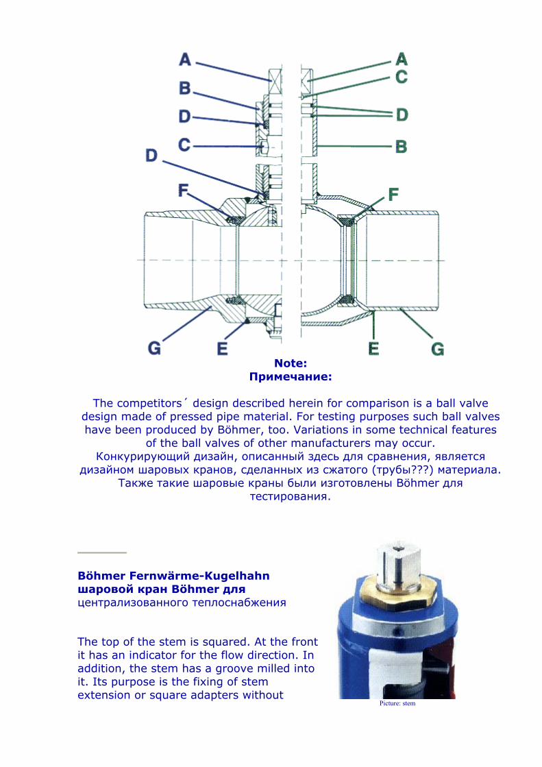
Note:
Примечание:
The competitors´ design described herein for comparison is a ball valve design made of pressed pipe material. For testing purposes such ball valves have been produced by Böhmer, too. Variations in some technical features
of the ball valves of other manufacturers may occur. Конкурирующий дизайн, описанный здесь для сравнения, является
дизайном шаровых кранов, сделанных из сжатого (трубы???) материала. Также такие шаровые краны были изготовлены Böhmer для
тестирования.
Böhmer Fernwärme-Kugelhahn шаровой кран Böhmer для централизованного теплоснабжения
The top of the stem is squared. At the front it has an indicator for the flow direction. In addition, the stem has a groove milled into it. Its purpose is the fixing of stem extension or square adapters without
Picture: stem
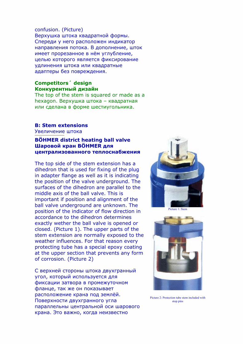
confusion. (Picture) Верхушка штока квадратной формы. Спереди у него расположен индикатор направления потока. В дополнение, шток имеет прорезанное в нём углубление, целью которого является фиксирование удлинения штока или квадратные адаптеры без повреждения.
Competitors´ design Конкурентный дизайн The top of the stem is squared or made as a hexagon. Верхушка штока – квадратная или сделана в форме шестиугольника.
B: Stem extensions Увеличение штока
BÖHMER district heating ball valve Шаровой кран BÖHMER для централизованного теплоснабжения
The top side of the stem extension has a dihedron that is used for fixing of the plug in adapter flange as well as it is indicating the position of the valve underground. The surfaces of the dihedron are parallel to the middle axis of the ball valve. This is important if position and alignment of the ball valve underground are unknown. The position of the indicator of flow direction in accordance to the dihedron determines exactly wether the ball valve is opened or closed. (Picture 1). The upper parts of the stem extension are normally exposed to the weather influences. For that reason every protecting tube has a special epoxy coating at the upper section that prevents any form of corrosion. (Picture 2)
С верхней стороны штока двухгранный угол, который используется для фиксации затвора в промежуточном фланце, так же он показывает расположение крана под землёй. Поверхности двухгранного угла параллельны центральной оси шарового крана. Это важно, когда неизвестно
Picture 1: Stem
Picture 2: Protection tube stem included with stop pins
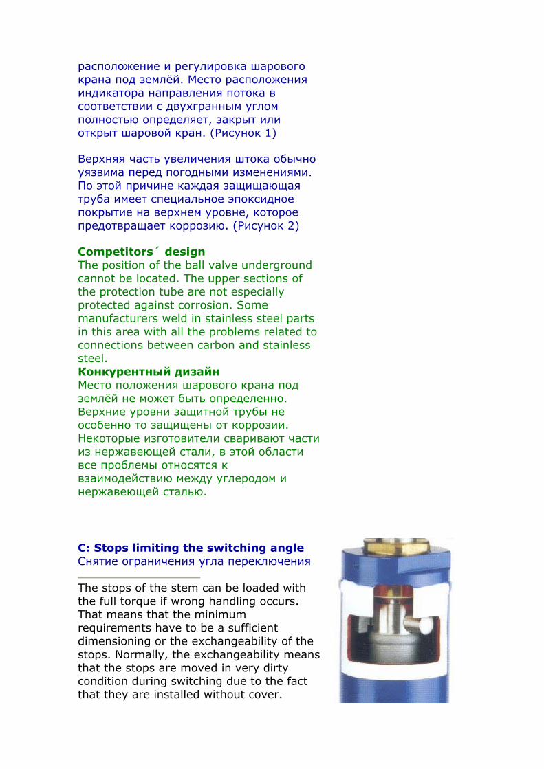
расположение и регулировка шарового крана под землёй. Место расположения индикатора направления потока в соответствии с двухгранным углом полностью определяет, закрыт или открыт шаровой кран. (Рисунок 1)
Верхняя часть увеличения штока обычно уязвима перед погодными изменениями. По этой причине каждая защищающая труба имеет специальное эпоксидное покрытие на верхнем уровне, которое предотвращает коррозию. (Рисунок 2)
Competitors´ design The position of the ball valve underground cannot be located. The upper sections of the protection tube are not especially protected against corrosion. Some manufacturers weld in stainless steel parts in this area with all the problems related to connections between carbon and stainless steel. Конкурентный дизайн Место положения шарового крана под землёй не может быть определенно. Верхние уровни защитной трубы не особенно то защищены от коррозии. Некоторые изготовители сваривают части из нержавеющей стали, в этой области все проблемы относятся к взаимодействию между углеродом и нержавеющей сталью.
C: Stops limiting the switching angle Снятие ограничения угла переключения
The stops of the stem can be loaded with the full torque if wrong handling occurs. That means that the minimum requirements have to be a sufficient dimensioning or the exchangeability of the stops. Normally, the exchangeability means that the stops are moved in very dirty condition during switching due to the fact that they are installed without cover.
Experience shows that dirt can get between the body and the stops and could prevent the ball from reaching its end position. If the ball is in almost closed position media can flow through the remaining gap between sealing and ball. This can damage the seals. Остановки штока могут быть загружены с полным вращающим моментом, если происходит не верное управление. Это означает, что минимальные требования должны быть подходящих размеров или изменяемость остановок. Обычно изменяемость означает, что остановки происходят в очень плохих условиях между выключениями из-за того, что они установлены без покрытия. Опыт показывает, что…
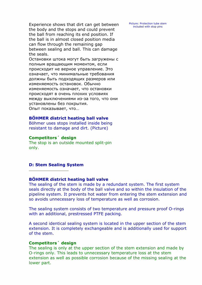
BÖHMER district heating ball valve Böhmer uses stops installed inside being resistant to damage and dirt. (Picture)
Competitors´ design The stop is an outside mounted split-pin only.
Picture: Protection tube stem included with stop pins
D: Stem Sealing System
BÖHMER district heating ball valve The sealing of the stem is made by a redundant system. The first system seals directly at the body of the ball valve and so within the insulation of the pipeline system. It prevents hot water from entering the stem extension and so avoids unnecessary loss of temperature as well as corrosion.
The sealing system consists of two temperature and pressure proof O-rings with an additional, prestressed PTFE packing.
A second identical sealing system is located in the upper section of the stem extension. It is completely exchangeable and is additionally used for support of the stem.
Competitors´ design The sealing is only at the upper section of the stem extension and made by O-rings only. This leads to unnecessary temperature loss at the stem extension as well as possible corrosion because of the missing sealing at the lower part.
E: Weld seams
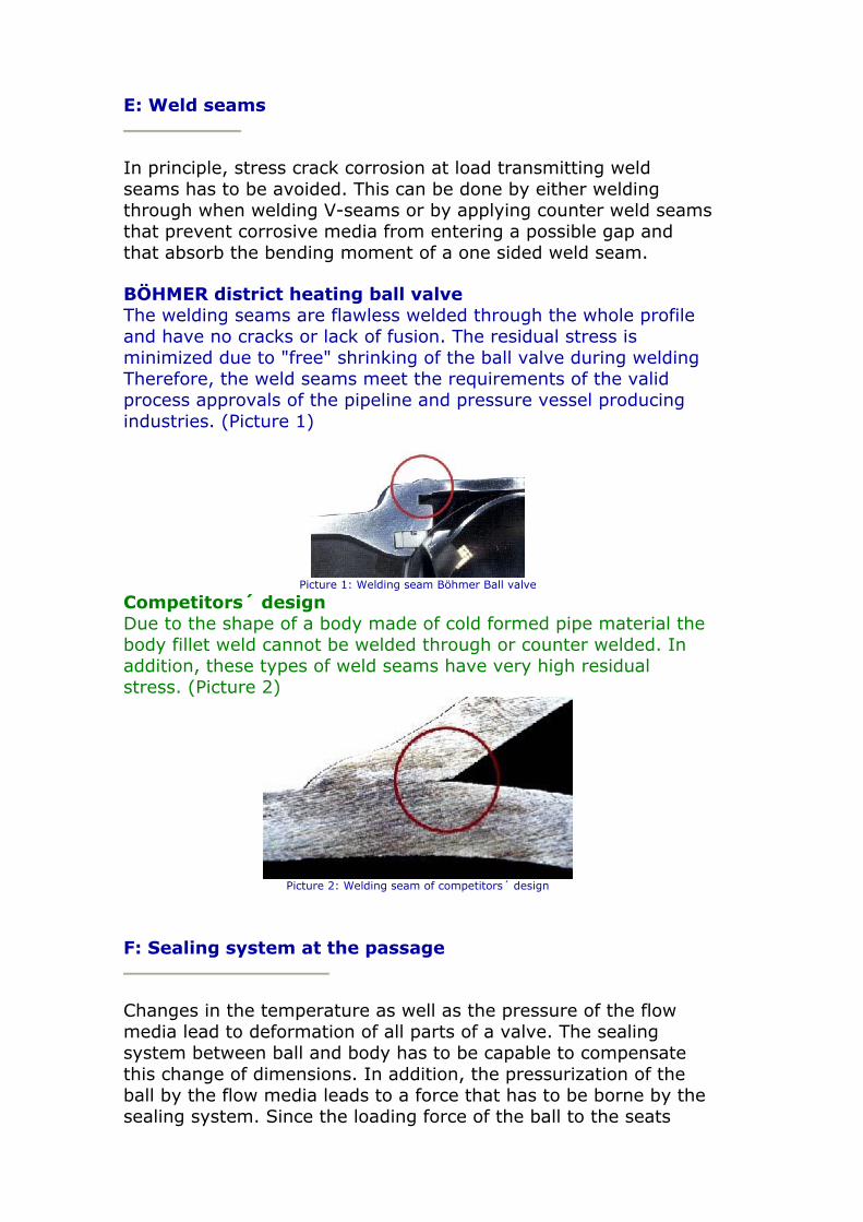
In principle, stress crack corrosion at load transmitting weld seams has to be avoided. This can be done by either welding through when welding V-seams or by applying counter weld seams that prevent corrosive media from entering a possible gap and that absorb the bending moment of a one sided weld seam.
BÖHMER district heating ball valve The welding seams are flawless welded through the whole profile and have no cracks or lack of fusion. The residual stress is minimized due to "free" shrinking of the ball valve during welding Therefore, the weld seams meet the requirements of the valid process approvals of the pipeline and pressure vessel producing industries. (Picture 1)
Picture 1: Welding seam Böhmer Ball valve
Competitors´ design Due to the shape of a body made of cold formed pipe material the body fillet weld cannot be welded through or counter welded. In addition, these types of weld seams have very high residual stress. (Picture 2)
Picture 2: Welding seam of competitors´ design
F: Sealing system at the passage
Changes in the temperature as well as the pressure of the flow media lead to deformation of all parts of a valve. The sealing system between ball and body has to be capable to compensate this change of dimensions. In addition, the pressurization of the ball by the flow media leads to a force that has to be borne by the sealing system. Since the loading force of the ball to the seats
increases quadraticly to the diameter inside the ball, already at DN150/ 6" and PN16/ANSI class 150 the charge at the seals as well as the torque and the wear is so high, that the ball shall be trunnion mounted. (AGFW/FVGW-rules, working sheet FW 410 - part 5, edition February 1999)
BÖHMER district heating ball valve In principle, Böhmer ball valves have trunnion mounted balls starting from DN150/ 6" and PN16/ ANSI class 150 (for pressures higher than PN16/ANSI class 150 for smaller diameters too). The sealing is designed according to the double block and bleed principle (Picture 1). The seat acts as a differential piston. If the ball valve is closed pressure builds up at the O-ring that is integrated at the outer diameter of the seat ring. This moves the seat ring against the trunnion mounted ball. For small pressure differences spring packages support the pressing. Coil spring packages are used having a longer service life and significant higher spring excursion than disc springs. The trunnion mounted ball takes up the load resulting from the pressure charging the ball.
Example: Diameter DN200/ 8" and working pressure PN25/ANSI class 300. This results in an axial force on the ball of 315 kN. (32 tons)
Because of the low pressing between ball and sealing no deformation occurs at the sealing if the ball is trunnion mounted, the wear due to possible dirt between ball and seat is minimized. Even if wear occurs due to dirt in the flow media the self-adjusting sealing system can compensate this. The complete sealing system including the spring packages is completely chambered in the body and thus prevented from dirt. Therefore, functionality is given at any time.
Picture 1: Böhmer-Sealing system, "Double-Block and Bleed" principlewith trunnion mounted ball.
1. Operational case:
Inlet pressure is higher than body or outlet pressure The O-ring

goes into position 1 and the access pressure moves with the piston surface (dda2 - da2)*π/4 the seat onto the ball. Due to the shape and the taking of the working pressure in the bearings the strain of the sealing material and the resulting wear is very low.
2. Operational case:
Inlet pressure is lower than body outlet pressure Because of excess pressure in the cavity, that means p2>p1, the O-ring moves into position 2. This causes a venting of the cavity or self-relief of the sealing system due to the fact that the differential piston is moved into the direction of the lower pressure p1. Thus, an inadmissible increase in pressure caused by changes in the volume of the water coming from thermal influences will be avoided.
Competitors´ design This design makes a trunnion mounted ball impossible. Contrary to the trunnion mounted ball, the floating ball is pressed against the seat rings which have to take the axial forces at the ball completely. This causes a high load and deformation of the seat rings which leads to higher torque rates. The wear due to possible dirt is much higher, too.
The open sealing system with disc springs is prone to contamination by dirt which can cause a negative influence on the low spring excursion. The result will be a further increase in the surface pressure at the seat rings. (Picture 2)
Picture 2: Sealing system of competitors´ design
G: Body material
In district heating systems, besides the load resulting from internal pressure from the flow media water, axial forces and bending moments caused by temperature differences occur. These forces can rapidly exceed the load due to the internal pressure. In
the worst case, this can cause malfunctioning of the components of the pipe system dimensioned too weakly. Since brittle materials cannot compensate tension peaks without cracking, the standard EN 253 requires the use of ductile, weldable material. The properties of these materials regarding yield strength and notched bar impact tenacity have been documented by a EN 10204.3.1.B material certificate (possibly a 3.1.A/C certificate). The ball valve body is part of the pipe system
BÖHMER district heating ball valve The use of massive forged carbon steel enables the compensation of axial forces (tensile and pressure load) as well as bending moments. In general, the requirements to cold embedded ball valves are met. The massive wall thickness, which is higher than those of the pipe system connected in every profile, has therefore a higher resistance to corrosion too. The forged steel is machined in a metal-cutting way only and so keeps its physical properties.
Competitors´ design The production of the body and the weld ends is done by cold forming of pipe parts. The occurring deformations change the structure of the material and thus the physical properties of the pipe material, too.
Many years ago, the Böhmer company tested the cold forming of pipe parts on machines purchased just for this purpose. The compensation of axial forces and bending moments caused by thermal loads in the district heating system require higher wall thickness at the body parts. Pipe parts with a sufficient wall thickness showed higher surface elongation and upsetting deformation leading to cracks, although more ductile material has been used. Measurements taken at the formed parts pointed to work-hardening (embrittlement) in the area of forming. The properties of ductility and tensile strength certified by the pipe producer were changed and tension cracks due to the local embrittlement were possible. Even an annealing of the parts did not lead to the original properties. Thus, a new material certificate is required for every single part.
Loss of flow
The demand to operate district heating system efficiently requires to minimize power losses. This enables an optimized design of the capacity when purchasing pumps and reduces the need for additional pumping capacity due to power loss as well. In the long run, the use of full bore ball valves has more advantages. The

higher costs in purchasing them (compared to reduced bore ball valves) are compensated within a minimum of time by saving costs due to the puchase of smaller, cheaper pumps. Ball valves with reduced bore have a higher pressure loss due to the internal shape diffuser/nozzle.
BÖHMER district heating ball valve We recommend the use of full bore ball valves because of the facts given above. Alternatively, we offer ball valves with reduced bore that are more cost-effective. At these designs the opening areas of the weld ends are turned over thus enabling an optimized contraction. The occurring power loss is minimized, unwanted drag does not occur.
Competitors´ design This design can only be made with reduced bore. Besides the above mentioned losses due to the diffuser/nozzle shape additional pressure losses occur at the seat rings which give additional drag. The flow resistance increases significantly and has to be compensated by higher pump capacities and so increase the operational costs.
Tightness test
Tightness test The "Double Block and Bleed" design enables the use of a bleeder plug at the body thus enabling the direct test of the functionality of the sealing system. On customer´s request´such a bleeder plug can be provided at every ball valve with trunnion mounted ball.
Competitors´ design A direct tightness test at the ball valve itself as described above is not possible because a trunnion mounted ball is impossible due to the general design.
Ball shape
For reasons of cost efficiency and while giving up on capacity savings hollow balls are used, too. Compared to solid balls with the round straight bores the manufacturer saves in general material due to smaller wall thickness. Since these hollow balls cause nearly the same pressure loss as a reduction of the diameter these balls are used mostly with reduced bore ball valves where pressure losses and the resulting capacity losses are not considered
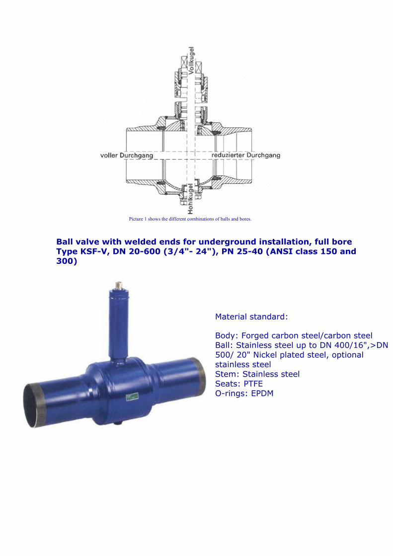
Picture 1 shows the different combinations of balls and bores.
Ball valve with welded ends for underground installation, full bore Type KSF-V, DN 20-600 (3/4"- 24"), PN 25-40 (ANSI class 150 and 300)
Material standard:
Body: Forged carbon steel/carbon steel Ball: Stainless steel up to DN 400/16",>DN 500/ 20" Nickel plated steel, optional stainless steel Stem: Stainless steel Seats: PTFE O-rings: EPDM

Options:
• Variable face-to-face dimension L • Variable stem extension H2 • Bleeder plug DN 150/ 6" • Drain and vent plugs • Higher wall thickness for extreme axial
loads or adder for corrosion • ANSI-design • Steam design
Ball valve with welded ends for underground installation, reduced bore Type KSF-R, DN 25-700 (1"- 28"), PN 25-40 (ANSI class 150 and 300)
Material standard:
Body: Forged carbon steel/carbon steel Ball: Stainless steel up to DN 400/ 16", >DN500/ 20" Nickel plated steel, optional stainless steel Stem: Stainless steel Seats: PTFE O-rings: EPDM
Options:
• Variable face-to-face dimension L • Variable stem extension H2 • Bleeder plug DN 150/ 6" • Drain and vent plugs • Higher wall thickness for extreme axial
loads or adder for corrosion • ANSI-design • Steam design
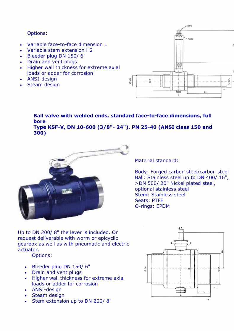
Ball valve with welded ends, standard face-to-face dimensions, full bore Type KSF-V, DN 10-600 (3/8"- 24"), PN 25-40 (ANSI class 150 and 300)
Material standard:
Body: Forged carbon steel/carbon steel Ball: Stainless steel up to DN 400/ 16", >DN 500/ 20" Nickel plated steel, optional stainless steel Stem: Stainless steel Seats: PTFE O-rings: EPDM
Up to DN 200/ 8" the lever is included. On request deliverable with worm or epicyclic gearbox as well as with pneumatic and electric actuator.
Options:
• Bleeder plug DN 150/ 6" • Drain and vent plugs • Higher wall thickness for extreme axial
loads or adder for corrosion • ANSI-design • Steam design • Stem extension up to DN 200/ 8"

(Standard 60 and 100mm)
<>
Ball valve with welded ends, standard face-to-face dimensions, reduced bore Type KSF-R, DN 15-700 (1/2"- 28"), PN 25-40 (ANSI class 150 and 300)
Werkstoffe Standard:
Body: Forged carbon steel/carbon steel Ball: Stainless steel up to DN 400/ 16", >DN 500/ 20" Nickel plated steel, optional stainless steel Stem: Stainless steel Seats: PTFE O-rings: EPDM
Up to DN 250/10" the lever is included. On request deliverable with worm or epicyclic gearbox as well as with pneumatic and electric actuator.
Options:
• Bleeder plug DN 150/6" • Drain and vent plugs • Higher wall thickness for
extreme axial loads or adder for corrosion
• ANSI-design • Steam design • Stem extension up to DN
200/8" (Standard 60 and 100mm)
<>
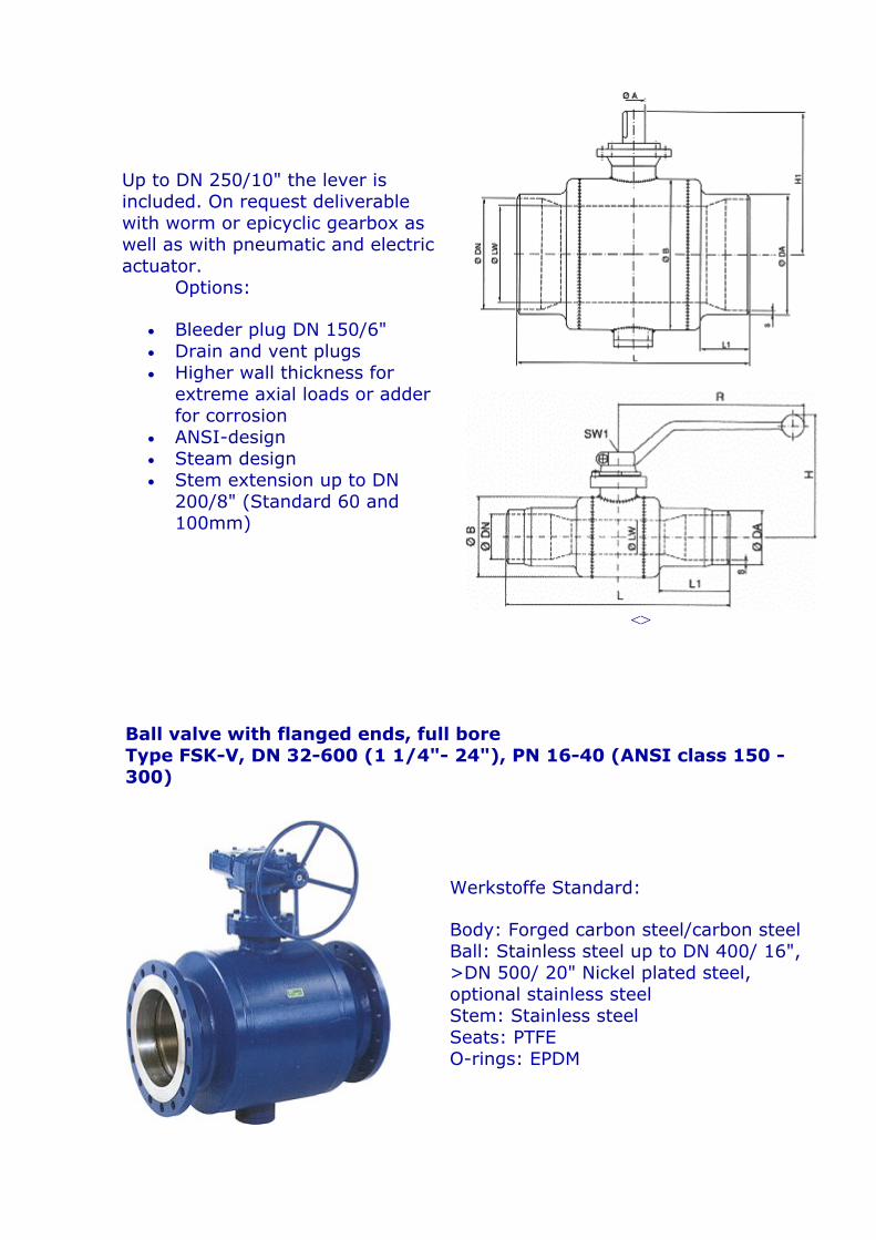
Ball valve with flanged ends, full bore Type FSK-V, DN 32-600 (1 1/4"- 24"), PN 16-40 (ANSI class 150 - 300)
Werkstoffe Standard:
Body: Forged carbon steel/carbon steel Ball: Stainless steel up to DN 400/ 16", >DN 500/ 20" Nickel plated steel, optional stainless steel Stem: Stainless steel Seats: PTFE O-rings: EPDM

Up to DN 200/8" the lever is included. On request deliver- able with worm or epicyclic gearbox as well as with pneu- matic and electric actuator.
Options:
• Bleeder plug DN 150/6" • Drain and vent plugs • Higher wall thickness for
extreme axial loads or adder for corrosion
• ANSI-design • Steam design • Stem extension up to DN
200/8" (Standard 60 and 100mm)
• Long pattern according to EN 558-1 FTF 28
<>
Ball valve with flanged ends, reduced bore Type FSK-R, DN 32-600 (1 1/4"- 24"), PN 16-40 (ANSI class 150- 300)
Material standard:
Body: Forged carbon steel/carbon steel Ball: Stainless steel up to DN 400/ 16", >DN 500/ 20" Nickel plated steel, optional stainless steel Stem: Stainless steel Seats: PTFE O-rings: EPDM
Up to DN 250/ 10" the lever is included. On request deliver-able with worm or epicyclic gearbox as well as with pneu-matic and electric actuator.
Options:
• Bleeder plug DN 150/ 6" • Drain and vent plugs • Higher wall thickness for extreme
axial loads or adder for corrosion • ANSI-design • Steam design • Stem extension up to DN 200/ 8"
(Standard 60 and 100mm) • Long pattern according to EN
558-1 FTF 28
<>
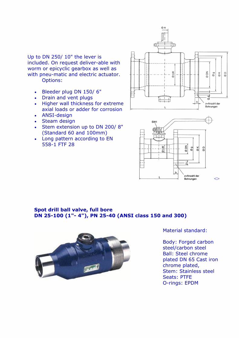
Spot drill ball valve, full bore DN 25-100 (1"- 4"), PN 25-40 (ANSI class 150 and 300)
Material standard:
Body: Forged carbon steel/carbon steel Ball: Steel chrome plated DN 65 Cast iron chrome plated, Stem: Stainless steel Seats: PTFE O-rings: EPDM

Options:
• Design with Flange/Weld end • Different connection at the stem • Higher wall thickness for extreme axial loads
or adder for corrosion • Steam design
Tie-in ball valve, full and reduced bore DN 15-100 (1/2"- 4"), PN 25-40 (ANSI class 150 and 300)
Material Standard:
Body: Forged carbon steel/carbon steel Ball: Stainless steel Stem: Stainless steel Seats: PTFE O-rings: EPDM

Options:
• Design with Flange/Weld end • Higher wall thickness for extreme
axial loads or adder for corrosion
• Steam design
<>
Ball valve with flanged and welded end, full and reduced bore DN 15-250 (1/2"- 10"), PN 25-40 (ANSI class 150 and 300)
Material Standard:
Body: Forged carbon steel/carbon steel Ball: Stainless steel Stem: Stainless steel Seats: PTFE O-rings: EPDM
Up to DN 250/ 10" the lever is included. On request deliverable with worm or epicyclic gearbox as well as with pneumatic and electric actuator.
Options:
• Higher wall thickness for extreme axial loads or adder for corrosion
• ANSI-design • Steam design • Stem extension up to DN 250/ 10"
(Standard 60 and 100mm)
<>
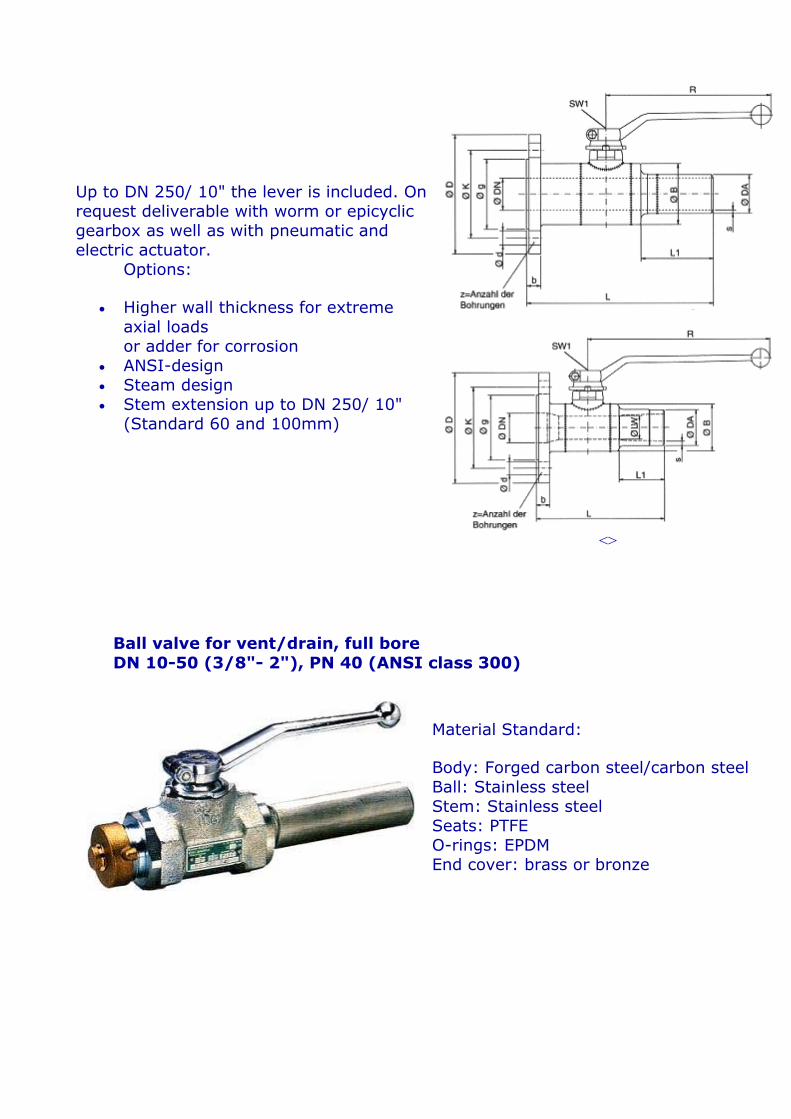
Ball valve for vent/drain, full bore DN 10-50 (3/8"- 2"), PN 40 (ANSI class 300)
Material Standard:
Body: Forged carbon steel/carbon steel Ball: Stainless steel Stem: Stainless steel Seats: PTFE O-rings: EPDM End cover: brass or bronze
Options:
• Steam design • Stem extension up to DN 50/ 2"
(Standard 60 and 100mm)
<>
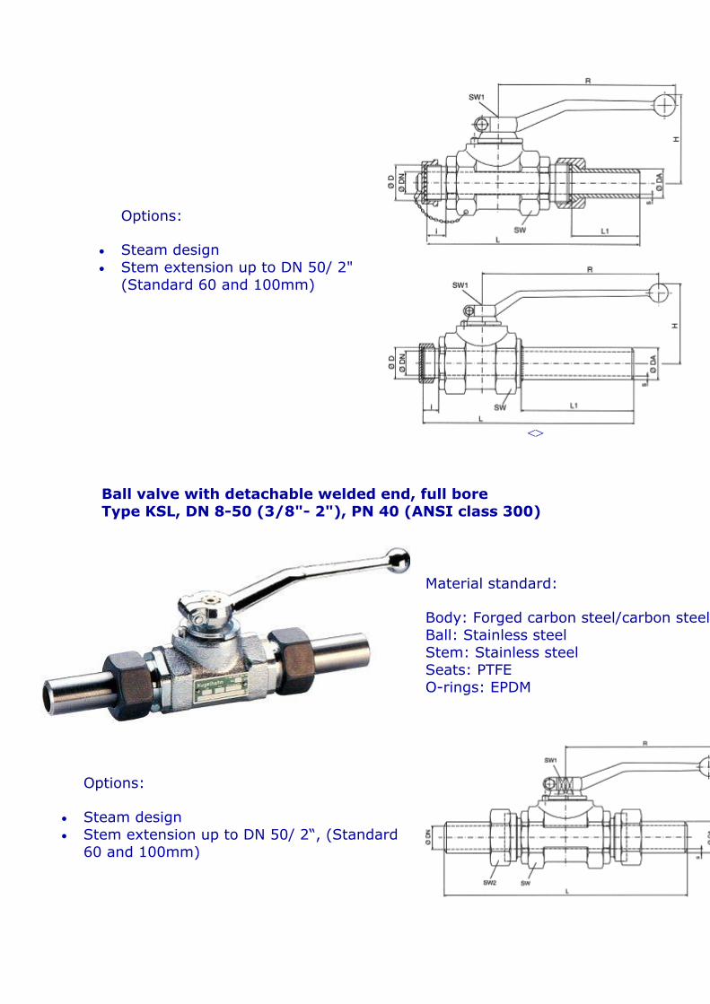
Ball valve with detachable welded end, full bore Type KSL, DN 8-50 (3/8"- 2"), PN 40 (ANSI class 300)
Material standard:
Body: Forged carbon steel/carbon steel Ball: Stainless steel Stem: Stainless steel Seats: PTFE O-rings: EPDM
Options:
• Steam design • Stem extension up to DN 50/ 2“, (Standard
60 and 100mm)

Ball valve with threaded ends, full bore Type KSG, DN 6-50 (1/4"- 2") , PN 16-40 (ANSI class 150- 300)
Material standard:
Body: Forged carbon steel/carbon steel Ball: Stainless steel Stem: Stainless steel Seats: PTFE O-rings: EPDM
Options:
• Steam design • Stem extension up to DN 50/ 2“,
(Standard 60 and 100mm)
Additional designs of ball valves and actuators More than 50.000 variants in our production range
Ball valves with insulation Flange and/or weld end up to DN 200
Ball valve with stem extension Standard 60 and 100mm for
Ball valve for drain Special coating for outside usage

DN 10-250
Ball valve for draining and venting stainless steel up to DN 50
Ball valve for pit line installation with bleeder and vent plugs
Ball valve made of brass threaded end DN 6-100
Ball valve for pit line installation with fixed epicyclic gearbox
Ball valve for pit line installation with electric actuator
Ball valve for underground installation with connector for tee-handle
P r o d u c t__ R a n ge
Fully welded ball valves
Straight-way ball valves,
Straight-way ball valves, threaded ports
KNG KMG KHG BNG BMG
DN 4-25 PN 25
DN 4-25 PN 63-100
DN 4-25 PN 150-500
DN 4-25 PN 25
DN 4-25 PN 63-100
BHG DN 4-25 PN 150-500
MKG DN 32-100 PN 16-315
MNG DN 4-25 PN 25
MLG DN 6-100 PN 16-32
Straight-way ball valves, flanged connection
FLL DN 10-300 PN 6-63
FDL DN 10-25 PN 10-250
FHL DN 40-50 PN 100-315
FKK DN 32-200 PN 6-160
FKK DN 250-300 PN 10-25
FKK DN 250-400 PN 10-40
FZL DN 15-100 PN 10-63
FZK DN 32-200 PN 10-40
FSL DN 10-100 PN 10-40
FSK DN 32-200 PN 10-40
FSK DN 250-400 PN 10-40
FSK DN 32-250 PN 10-40
FSK DN 300-500 PN 10-40
FKA DN 15-50 Class 600
FZA DN 15-200 Class 150, 300
FSA DN 15-400 Class 150,300
FSA DN 250-500 Class 150, 300
Straight-way ball valves, welded ends

KSL DN 8-25 PN 25
KSF DN 10-500 PN 25
Straight-way stainless steel ball valves
ENG DN 4-50 PN 25-400
EBG DN 4-25 PN 25-400
EMG DN 6-50 PN 40-63
EDG DN 10-100 PN 25-40
EDS DN 10-100 PN 25-40
ELF DN 10-50 PN 10-40
EKF DN 32-200 PN 10-40
Multi-way ball valves
DNG DN 3-40 PN 25
DHG DN 3-40 PN 63-400
VNG DN 3-40 PN 25
VHG DN 3-40 PN 63-400
DUN DN 10-25 PN 25
DUH DN 10-25 PN 100-350
DNF DN 15-100 PN 10-40
VNF DN 15-100 PN 10-40
DUF DN 50-100 PN 10-40
Special designs
Besides the ball valves mentioned on this site, we manufacture tailor made according to customers specification. This site shows some typical examples of special ball valves.
Ball valve with vacuum small flange
Ball valve with dependance
switching
Block ball valve for plate mounting
Ball valve with spindle
extension
Ball valve combination
Ball valve with heating jacket
Ball valve with pipe socket
Ball valve with automatic
closing device

Control ball valve
Ball valve with lock
Ball valve with threaded connection and welded tail piece, fully welded
Ball valve with flange
connection and welded tail piece, fully
welded
Multiplex ball valve for automatic welders High-pressure
ball valve for solid matters
Compact ball valve for insertion between opposed flanges
Ball valve with conduction for equalization of
pressure
Angular ball valve for
propane tank
Ball valve with prolonged slip-on actuator for underground installation
Ball valve for tunnel-driving
device with rinsing
connection
... Further sites regarding our product range are currently under construction...
A p p l i c a t i o n
On the following pages you can find more information regarding our Range
of Application.
District Heating/steam
Ball valves for all-gas
Application:

Böhmer all-gas ball valves have been tested by DVGW Deutscher Verein des Gas- und Wasserfaches e.V. (German Gasw and Water Industrial Association) and certified to standard. Up to 4 bars according to DIN 3537, as HAE with testing for 650°, up to 16 bars according to DIN 3547, more than 16 bars up to 100 bars according to DIN 3437 with tÜV testing of structural members.
Identification: DIN-DVGW mark with registration number.
Thus, Böhmer ball valves manufactured from suitable materials for body, ball and seals, can be used for all gases according to the DVGW work-sheet G 269/I.
Requirements and tests according to DIN 3230, section 5, are complied with.
Ball valves for acetylene / oxygen
Application: Böhmer ball valves for acetylene have been tested by BAM Federal Institute for Material Testing and meet the requirements for shut-off devices for high-pressure-acetylene pipes, by withstanding the forces of detonation of acetylene decay in completely open as well as closed position.
Marking: Name plate yellow / type registration no.
Thus Böhmer ball valves are applicable for shut-off devices and as quick-acting ball valve for acetylene plants in accordance with TRAC 204 and 206 technical standard.
Application: Böhmer Ball valves for oxygene are constructed to meet the generally recognized technical regulations and prevent burnout. Qualification and applicability for oxygen pressure of up to 40 bar as well as temperatures up to +60 °C have been certified by BAM Federal Institute of Material Testing.
Marking: Name plate blue / free of oil and grease
Thus Böhmer Ball valves can be used as stop valves for oxygen plants and oxygen lines according to accident prevention rule 44.0
Ball valves fire-safe design
Application: Böhmer fire-safe ball valves have been designed that in case of fire, metallic seal seats, together with heat-resistent materials, will provide an emergency sealing. This guarantees safe operation in emergencies even at temperatures above +650°C.
In compliance with the specifications of BS 6755, section 2, 1987, Böhmer ball valves were tested by the independent Soba Test Institute and are allowed to be classified as fire-safe.
Due to this classification, Böhmer fire-safe type ball valves can be used in, among others, the petrochemical and gas industries.
Ball valves with structural component test
Application: Böhmer ball valves for gas and hazardous liquids have been component tested by the RW TÜV according to the VdTÜV instruction sheet 1065
By being awarded the component identification sign by VdTÜV, Böhmer ball valves meet the following requirements from German official guiding rules and standards:
• Regulations for inflammable liquids (VbF) • Regulations for high pressure gas pipeline (GAS-HL-VO) • VdTÜV instruction sheet pipelines 1065 • DIN 3230 section 5 • DIN 3230 section 6
Thus, Böhmer ball valves made from suitable materials for body, ball and seals, can be used for flow media within the scope of application mentioned before.
Further sites regarding application range are currently under construction...


![.RFDHOLhQLYHUVLWHVL7ÖS)DN OWHVL dRFXN6DùOÖùÖYH ...tip.kocaeli.edu.tr/docs/cocuksagligihastaliklarianabilimdali/... · y ç ã_aá_ ã]\c`e Ç ã]a\ ãab y GD kötü, entübe](https://static.fdocuments.net/doc/165x107/5d59a8d288c993be088b6e7e/rfdholhqlyhuvlwhvl7oesdn-owhvl-drfxn6duooeuoeyh-tip-y-c-aaa-ace.jpg)


![]m¿-´n-]-{X-{]-h¿-ØIs Hm¿--°p-dn-pI · aq-cym-Sv am¸n-f FÂ.]n. kv-¡qÄ, Ip-¯p-]d-¼v t_mÀ-Uv kv-¡qÄ, sXm-¡n-e-§m-Sn l-bÀ sk-¡ï-dn kv-¡qÄ, ^m-dq-Jv tIm-tf-Pv F-¶n-h-S-§fnÂ](https://static.fdocuments.net/doc/165x107/5f1e0178041cd92a8a691fe4/m-n-x-h-is-hm-p-dn-pi-aq-cym-sv-amn-f-fn-kv-q-ip-p-d-v.jpg)


![sunu 3 ölçme - formasyon.erdogan.edu.trformasyon.erdogan.edu.tr/Files/ckFiles/file/ölçme_sunu3.pdf · z d Ç Ç ] } r v m v ] À ] ] (÷lwlp )dn owhvl 3hgdjrmln )rupdv\rq](https://static.fdocuments.net/doc/165x107/5ed51f6a7e8ff57f6f41eda6/sunu-3-flfme-lmesunu3pdf-z-d-r-v-m-v-lwlp-dn.jpg)


