Nokia’s NetMonitor Manual - psg.com · PDF fileNokia’s NetMonitor Manual Version...
36
Nokia’s NetMonitor Manual Version 0.8 by FlipO This is the first release of a complete Netmonitor manual for Nokia phones. For now it only contains the simple specifications for the great majority of screens. If you aren’t already familiar with nokia’s netmonitor, please wait for the definitive version, probably v1.0. For now I am just releasing this for people to give suggestions and make corrections if necessary. Phone Models/Software versions 31xx/81xx Old phones netmonitor has some differences when compared with the newer models, but this manual can be used as a guide, because the overall working method and the info given by the phone is very similar. However, I won’t get into more details about old/new phones netmonitor differences for now. 51xx/61xx/71xx/88xx/91xx/32xx This document covers the majority of menus from these phones netmonitor. Some of them may have little differences, like missing/additional menus, different info, etc. The goal right now is to make an accessible manual, that will get better over the time. Please contribute with all the info that you find relevant. Information Sources Almost all the info available at the moment comes from an official document from Nokia. Some things were added, based on personal experiences and friends contributions. I expect to add more details based on email replys from people reading this document. Please use the email at the end of the file for suggestions Things To Do: • Distribute this document in adobe .pdf format (does anybody nows where I can get Adobe Acrobat Full Version? ☺ • Add a small section that explains how can some netmonitor information can be used by the simple user (battery charging, network details, that kind of things that can be used by non-technical people. • Change the visual aspect of this manual, making it a good-looking document to print out. (please send me some examples of how you would like to see this… you are free to send me other documents that look nice, so that I can take some ideas. • Suggestions? Menu Modes There are three Menu Display modes: - execute mode - data display mode - help mode Different modes are marked in this manual as follows: ************** ++++++++++++++ ############## * * + + # # * Execute * +Data display+ # Help # * Mode * + Mode + # Mode # * * + + # # ************** ++++++++++++++ ############## 1
Transcript of Nokia’s NetMonitor Manual - psg.com · PDF fileNokia’s NetMonitor Manual Version...
Nokia’s NetMonitor Manual Version 0.8 by FlipO This is the first release of a complete Netmonitor manual for Nokia phones. For now it only contains the simple specifications for the great majority of screens. If you aren’t already familiar with nokia’s netmonitor, please wait for the definitive version, probably v1.0. For now I am just releasing this for people to give suggestions and make corrections if necessary.
Phone Models/Software versions
31xx/81xx
Old phones netmonitor has some differences when compared with the newer models, but this manual can be used as a guide, because the overall working method and the info given by the phone is very similar. However, I won’t get into more details about old/new phones netmonitor differences for now.
51xx/61xx/71xx/88xx/91xx/32xx
This document covers the majority of menus from these phones netmonitor. Some of them may have little differences, like missing/additional menus, different info, etc.
The goal right now is to make an accessible manual, that will get better over the time. Please contribute with all the info that you find relevant.
Information Sources
Almost all the info available at the moment comes from an official document from Nokia. Some things were added, based on personal experiences and friends contributions. I expect to add more details based on email replys from people reading this document.
Please use the email at the end of the file for suggestions
Things To Do:
• Distribute this document in adobe .pdf format (does anybody nows where I can get Adobe Acrobat Full Version? ☺
• Add a small section that explains how can some netmonitor information can be used by the simple user (battery charging, network details, that kind of things that can be used by non-technical people.
• Change the visual aspect of this manual, making it a good-looking document to print out. (please send me some examples of how you would like to see this… you are free to send me other documents that look nice, so that I can take some ideas.
• Suggestions?
Menu Modes There are three Menu Display modes: - execute mode - data display mode - help mode Different modes are marked in this manual as follows: ************** ++++++++++++++ ############## * * + + # # * Execute * +Data display+ # Help # * Mode * + Mode + # Mode # * * + + # # ************** ++++++++++++++ ##############
1

The execute mode is entered from the menu by scrolling and selecting or shortcut. If the test index entered pertains to a test that resets a timer (test 80) for example, then the timer is reset as soon as the Ok button has been pressed in the menu, and the data display mode takes over. In other words, the execute mode is of the one-shot type. To run another test in the execute mode, the Field Test Display menu must be re-activated. During the data display mode, the field test data (e.g. carrier, power level, cell) is visible on the main display. During the help mode, one screen of instructions is shown for each test to make it easier to identify the test in question. A long press of asterisk (*) is used to toggle between these two modes. (on some 3110 versions, the help screens follow the data display modes on the list) The arrow keys (^,v) offer an easy way to switch to another test without using the menu. However, the data display mode remains, i.e. nothing will be executed or set on although such tests would be passed. This is to prevent the user from accidentally clearing any valuable data. (see 3.7.2 for details and 2.5 for recommendations). The help mode is also a non-execute mode. Display numbers have been selected in such way that no 5-terminated test number is an execute display.
2
Display 1 – Serving cell info
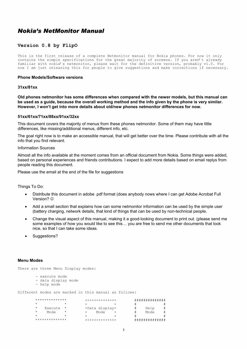
++++++++++++++ ############## +abbb ccc ddd+ #CH RxL TxPwr# + e ff g mmmm+ #TS TA RQ RLT# + nnn ppp+ # C1 C2 # + oooo + # CHT # ++++++++++++++ ##############
a H, if carrier numbers are scrolled when hopping is on. Otherwise ' '. bbb When mobile is on TCH:
DCH carrier number in decimal. When mobile is NOT on TCH:
CH means carrier number in decimal. If hopping is on, used channels are scrolled when display is updated.
ccc rx level in dBm, minus sign not shown if <=-100 ddd tx power level. If transmitter is on, symbol * is shown in front of the power
level value. e Time Slot, range is 0 - 7 ff Timing advance, range is 0 – 63 (see apendix XXXXX) g rx quality (sub), range is 0 - 7 mmmm Radio Link Timeout value. If value is negative, 0 is shown.
Maximum value is 64. When mobile is NOT on TCH then xx is shown. nnn value of the path loss criterium (C1). Range is -99 - 999. oooo type of current channel:
THR0 : TCH HR subchannel 0 THR1 : TCH HR subchannel 1 TFR : TCH FR TEFR : TCH EFR F144 : TCH FR data channel, speed 14.4 kbps F96 : TCH FR data channel, speed 9.6 kbps F72 : TCH FR data channel, speed 7.2 kbps F48 : TCH FR data channel, speed 4.8 kbps F24 : TCH FR data channel, speed 2.4 kbps H480 : TCH HR data channel, speed 4.8 kbps, subch 0 H481 : TCH HR data channel, speed 4.8 kbps, subch 1 H240 : TCH HR data channel, speed 2.4 kbps, subch 0 H241 : TCH HR data channel, speed 2.4 kbps, subch 1 FA : TCH FR signalling only (FACCH) channel FAH0 : TCH HR signalling only (FACCH) channel, subch 0 FAH1 : TCH HR signalling only (FACCH) channel, subch 1 SDCC : SDCCH AGCH : AGCH CCCH : CCCH CBCH : CCCH and cell broadcast receiving on BCCH : BCCH SEAR : SEARCH NSPS : MS is in No Serv Power Save state
ppp value of the cell reselection criterium (C2). Range is -99 - 999. If phone is phase 1 then C1 value is shown.
3

Display 2 – More info about serving cell ++++++++++++++ ############## + aa b c Bdd + #PM RAR Ro BC# + ee f + #RelR QLF # + ggg hh iii + #CRO TO PenT # + H=j mm nn + #H MAIO HSN # ++++++++++++++ ##############
aa paging mode
NO : normal paging EX : extended paging RO : paging reorganization SB : same as before
b maximum number of Random Access retransmission c roaming indicator, values are R or empty. Bdd Letter B and BSIC value, range is 0 - 63. ee Reason of last call release f RX quality (full), range is 0 - 7 ggg Cell reselect offset, range 0 - 126 dB.
0 - 63 * 2 dB. 'xxx' in active mode. hh Temporary offset, range 0 - 60 dB.
0 - 7 * 10 dB. 70 dB means infinite time. 'xx' in active mode.
iii Penalty time, range 0 - 620 s. 0 - 31 * 20 s. 'xxx' in active mode.
j Hopping channel 0 Single RF channel 1 RF hopping channel
mm mobile allocation index offset, MAIO Range: 00 to 63 / xx when H=0
nn hopping sequence number, HSN Range: 00 to 63 / xx when H=0
Display 3 – Serving cell, 1st and 2nd neighbour ++++++++++++++ ############## +aaabbbcccddd+ #SCH C1 rx C2# +aaabbbcccddd+ #1CH C1 rx C2# +aaabbbcccddd+ #2CH C1 rx C2# + ef gh + # 1N 2N # ++++++++++++++ ##############
1. row: serving cell information 2. row: 1. neighbour information 3. row: 2. neighbour information 4. row, ef: 1. neighbour information 4. row, gh: 2. neighbour information
aaa carrier number in decimal bbb C1 value, range is -99 - 999, displayed only in idle mode.
Instead of C1 value, letter 'B' and BSIC value will be displayed in active mode. ccc rx level in dBm, minus sign not shown if <=-100 ddd C2 value, range is -99 - 999 e,g F is shown if cell is in a forbidden location area otherwise location is empty. f,h B is Barred, N is normal priority and L is low priority otherwise location is
empty.
4

Display 4 – 3rd, 4th and 5th neighbour cells ++++++++++++++ ############## +aaabbbcccddd+ #3CH C1 rx C2# +aaabbbcccddd+ #4CH C1 rx C2# +aaabbbcccddd+ #5CH C1 rx C2# + ef gh ij + # 3N 4N 5N # ++++++++++++++ ##############
1. row: 3. neighbour information 2. row: 4. neighbour information 3. row: 5. neighbour information 4. row, ef: 3. neighbour information 4. row, gh: 4. neighbour information 4. row, ij: 5. neighbour information
aaa carrier number in decimal bbb C1 value, range is -99 - 999, displayed only in idle mode.
Instead of C1 value, letter 'B' and BSIC value will be displayed in active mode. ccc rx level in dBm, minus sign not shown if <=-100 ddd C2 value, range is -99 - 999 e,g,I F is shown if cell is in a forbidden location area otherwise location is empty. f,h,j B is Barred, N is normal priority and L is low priority otherwise location is
empty.
Display 5 – 6th, 7th and 8th neighbour cells ++++++++++++++ ############## +aaabbbcccddd+ #6CH C1 rx C2# +aaabbbcccddd+ #7CH C1 rx C2# +aaabbbcccddd+ #8CH C1 rx C2# + ef gh ij + # 6N 7N 8N # ++++++++++++++ ##############
1. row: 6. neighbour information 2. row: 7. neighbour information 3. row: 8. neighbour information 4. row, ef: 6. neighbour information 4. row, gh: 7. neighbour information 4. row, ij: 8. neighbour information
aaa carrier number in decimal bbb C1 value, range is -99 - 999, displayed only in idle mode.
Instead of C1 value, letter 'B' and BSIC value will be displayed in active mode. ccc rx level in dBm, minus sign not shown if <=-100 ddd C2 value, range is -99 - 999 e,g,i F is shown if cell is in a forbidden location area otherwise location is empty. f,h,j B is Barred, N is normal priority and L is low priority otherwise location is
empty.
5

Display 6 – Network selection display
############## #LReg 1_For# #1_Pre 2_For# #2_Pre 3_For# #3_Pre 4_For# ##############
This display shows the last registered network country code and network code as well as the codes for four forbidden networks and the first 3 preferred networks. ++++++++++++++ +aaabb aaabb+ +aaabb aaabb+ +aaabb aaabb+ +aaabb aaabb+ ++++++++++++++ If three digit MNC is used (DCS1900), display looks different: ++++++++++++++ +aaabbbaaabbb+ +aaabbbaaabbb+ +aaabbbaaabbb+ +aaabbbaaabbb+ ++++++++++++++ 1. row: last registered network - 1st forbidden network 2. row: 1st preferred network - 2nd forbidden network 3. row: 2nd preferred network - 3rd forbidden network 4. row: 3rd preferred network - 4th forbidden network aaa country code coded in BCD bbb network code coded in BCD, third digit can be 'F'
6
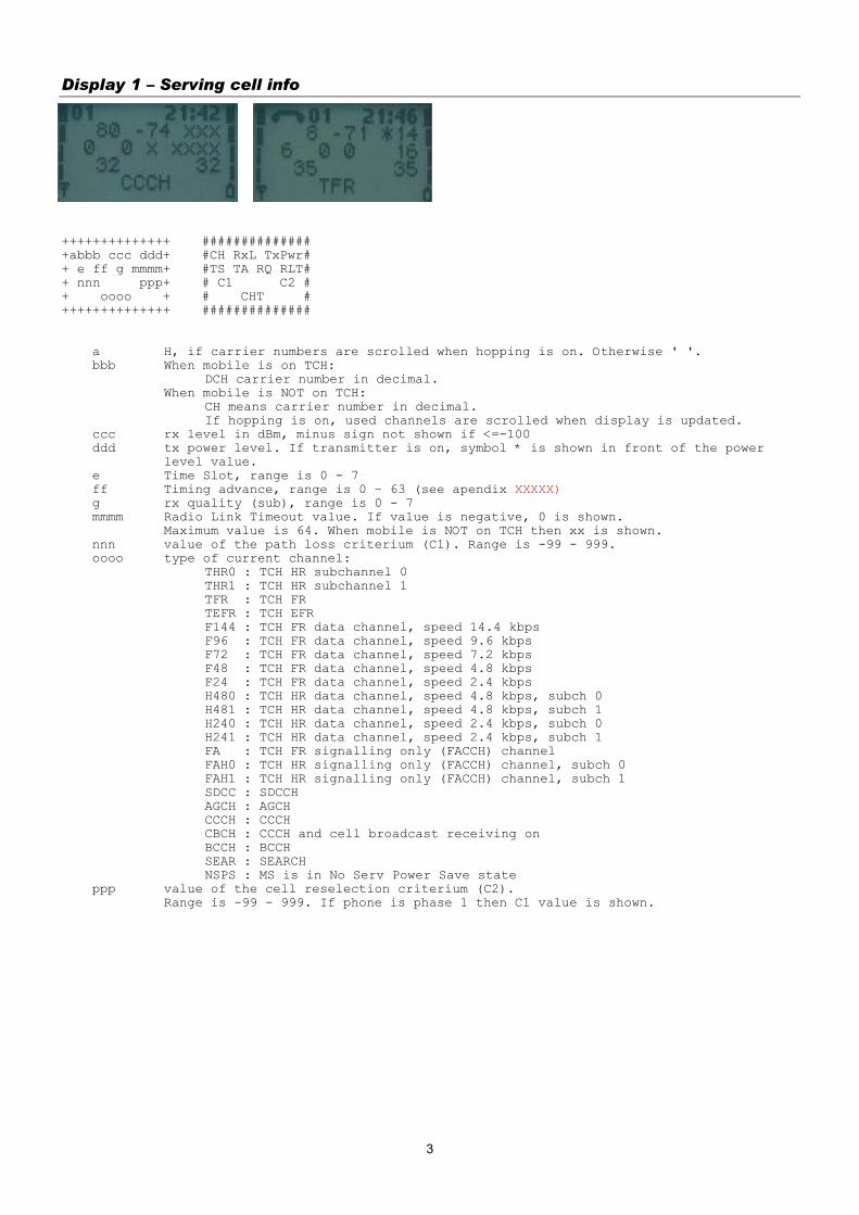
Display 7 – System information bits for serving cell ++++++++++++++ ############## +E A H C I BR+ #Serving Cell# +a b c d e fg+ #System Info # +ECSC 2Ter MB+ #Bits # + h i j+ # # ++++++++++++++ ##############
a 1 is shown if emergency calls are supported, else 0 b 1 is shown if attach-detach-procedure is allowed, else 0 c 1 is shown if half rate channels are supported, else 0 d 1 is shown if C2 values are broadcasted, else 0 e 1 is shown if system information 7 and 8 are broadcasted, else 0 f 1 is shown if cell broadcast is supported, else 0 g 1 is shown if re-establishment is supported, else 0
The following items are used only in dualband phones:
h In idle mode 1 is shown if Early Classmark (ECSC) sending is supported, else 0. In dedicated mode (conversation) X is shown.
i In idle mode 1 is shown if 2-Ter messages are supported, else 0.
In dedicated mode (conversation) X is shown. j MultiBand reporting decimal value (0,1,2,3) is shown if supported.
This is shown both in idle and dedicated mode. The following is picked from Phase2+ ETSI GSM 05.08 version 5.4.0, Section 8.4.3 ""Additional cell reporting requirements for multi band MS"".
For a multi band MS the number of cells, for each frequency band supported, which shall be included in the measurement report is indicated by the parameter, MULTIBAND_REPORTING. The meaning of different values of the parameter is specified as follows:
Value Meaning 0 (00) Normal reporting of the six strongest cells, with known and allowed NCC part
of BSIC, irrespective of the band used. 1 (01) The MS shall report the strongest cell, with known and allowed NCC part of
BSIC, in each of the frequency bands in the BA list, excluding the frequency band of the serving cell. The remaining positions in the measurement report shall be used for reporting of cells in the band of the serving cell. If there are still remaining positions, these shall be used to report the next strongest identified cells in the other bands irrespective of the band used.
2 (10) The MS shall report the two strongest cells, with known and allowed NCC part
of BSIC, in each of the frequency bands in the BA list, excluding the frequency band of the serving cell. The remaining positions in the measurement report shall be used for reporting of cells in the band of the serving cell. If there are still remaining positions, these shall be used to report the next strongest identified cells in the other bands irrespective of the band used.
3 (11) The MS shall report the three strongest cells, with known and allowed NCC
part of BSIC, in each of the frequency bands in the BA list, excluding the frequency band of the serving cell. The remaining positions in the measurement report shall be used for reporting of cells in the band of the serving cell. If there are still remaining positions, these shall be used to report the next strongest identified cells in the other bands irrespective of the band used.
7

Display 10 – Paging Repeat Period, TMSI, Location Update Timer, AFC and AGC ++++++++++++++ ############## +TMSIaaaaaaaa+ #TMSI(hex) # +T321:bbb/ccc+ #T3212ctr/tim# +PRP:d ee ff+ #PaRP DSF AGC# + ggggg hhh + # AFC Ch # ++++++++++++++ ##############
aaaaaaaa TMSI value in hex format bbb Current value of T3212 counter (range is 000 - 'ccc', where 1 means 6 min
time. So, if this value is 2 less than 'ccc' then next periodic location updating will be made within 2 * 6 min = 12 minutes.
ccc Timeout value of T3212 counter (range is 000 - 240, where 1 means 6 min time between location updates and 240 means 240 * 6 min = 24 h between location updates. 000 means that periodic location update is not in use.) This value is received from the network.
d Value of paging repeat period (range is 2 - 9, when paging is in every second multiframe, mobile takes more current than if it were in every 9th multiframe)
ee Downlink signalling failure value. If value is negative, 0 is shown. Maximum value is 45. When mobile is on TCH then xx is shown.
ff Gain value on TCH/SDCCH, range is 0 - 93 ggggg VCTCXO AFC DAC control, range is -1024 - 1023 hhh Serving cell channel number
Display 11 – Network parameters ++++++++++++++ ############## +CC:aaa NCbbb+ # MCC MNC # + LAC:ccccc + #LocAreaCode # + CH : dddd + #ServChannel # + CID:eeeee + # CellId # ++++++++++++++ ##############
aaa MCC value in decimal (MCC=Mobile Country Code) bbb MNC value in decimal (MNC=Mobile Network Code)
Three digits are shown only in DCS1900. In other systems only two digits are shown.
ccccc LAC value in decimal (LAC=Location Area Code) dddd Serving cell channel number eeeee Cell Identifier in decimal format
Some software versions display LAC and CID differently. These can be shown in hex format or even both decimal and hexadecimal formats on the same line.
Display 12 – Cyphering, hopping, DTX Status and IMSI ++++++++++++++ ############## +CIPHER :aaa + #CipherValue # +HOPPING:bbb + #HoppingValue# +DTX :ccc + #DTXValue # +IMSI :ddd + #IMSIAttach # ++++++++++++++ ##############
aaa ciphering value, OFF/A51/A52 bbb hopping value, ON/OFF ccc DTX value ON/OFF ddd IMSI attach
ON : IMSI attach on OFF : IMSI attach off
These values are updated only on the TCH.
8
Display 13 – Uplink DTX switching display ************** ############## *aaaaaaaaaa * #DTXMode # *DTX(DEF):bbb* #DefaulDTXSta# *DTX(BS) :ccc* #DTXValFromBS# * * # # ************** ##############
With this display it is possible to change MS to use DTX or not, if BS allows MS to decide it. This display must be activated from MENU to change DTX state. When MENU is not active and the user is scrolling field test displays with NEXT and PREVIOUS, the DTX state will not change. aaaaaaaaaa status of switched mode. DTX:ON : MS uses DTX DTX:OFF : MS does not use DTX DTX:DEF : MS use default state of DTX. Defined in MS_PAR.H NOTALLOWED: BS does not allow MS to decide if it uses DTX or not. bbb default state of DTX. Defined in MS_PAR.H The value is either ON or OFF ccc is DTX value from BS MAY : BS allows MS to decide if it uses dtx or not on uplink. USE : BS controls MS to use dtx (on uplink) NOT : BS controls MS not to use dtx (on uplink) HELP display:
Display 14 – Toggle Screening Indicator When selected, changes the value of Screening Indicator from 0 to 1 and vice versa. ************** ************** * SCREENING * * SCREENING * * INDICATOR * * INDICATOR * * IS 00 * * IS 01 * * * * * ************** ************** HELP display: ############## #Use menu to # # change # # Screening # # indicator # ##############
9

Display 17 – Switch BTS_Test Status ############## #Use menu to # #toggle BTS # #test ON/OFF # # # ##############
************** ************** * * * * * BTS TEST * * BTS TEST * * ON * * OFF * * * * * ************** ************** Mobile is Mobile is searching only behaving normally. one frequency. Neighbour measurements Neighbour measurements are done. are not done. This display is used to toggle BTS_TEST status on EEPROM. If BTS_TEST status is set on EEPROM each time the mobile sends a search list it uses only the carrier number stored on SIM SCM-location 33. Also the neighbour information from system information messages is ignored. If the BTS_TEST status is not set, then the value of SIM SCM-location 33 is ignored and the mobile behaves normally (i.e. does the neighbour measurements according the GSM specifications). To activate BTS tests perform following steps: - Save desired channel number in SIM SCM-location 33. - Select display 17 in execute mode - Switch power off and on If activation succeeded, there is text "BTS TEST ON" in display 17. To deactivate BTS tests either select display 17 in execute mode or save number 0 in SIM SCM-location 33 and switch power off and on. NOTE! The display does not show the value of BTS_TEST status in EEPROM. Although the value is set, bts test can be off. If there is not legal carrier number in SIM location 33 (GSM: 1-124, DCS1800: 512-885) the display shows that bts test is off. Also if the mobile was already registered to some carrier before switching BTS_TEST status, the display can show different value from the one in EEPROM.
Display 18 – Lights status control Forces keyboard and display lights on/off while displaying any netmonitor screen. ************** ************** * * * * * LIGHTS * * LIGHTS * * ON * * OFF * * * * * ************** ************** ############## #Use menu to # # toggle # # lights # # ON/OFF # ##############
10
Display 19 – Toggle Cell Barred Status ############## #Use menu to # #toggle cell # #barr status # #DIS/ACC/REV # ##############
************** ************** ************** * * * * * * * CELL BARR * * CELL BARR * * CELL BARR * * ACCEPTED * * REVERSE * * DISCARD * * * * * * * ************** ************** ************** This test is meant to be used when some cells are tested prior taking them into commercial use. By setting the barring on in the base station normal GSM phones will not try to register these barred cells. By selecting cell barring reversed, the MS will only use the cells to be tested. However, if at the same time it is wanted that MS will be capable to use normal network cell barring ignored can be set. Display 19 will show the cell barring mode. NOTE! If a cell has been selected before barring state is changed the selected cell may have different barring state than what the display shows. After reselection the cell barring state is working for sure.
11
Display 20 – Charging status ************** ############## * aaa bbbbb * #BatVol ChMod# * Tccc dddd * #Btemp ChTime# * Ceee Wfff * #ChrgVol Pwm # * gggg hhhh * # Btyp BFDC # ************** ##############
aaa Battery voltage in decimal, range is 0.00 - 9.99 V, decimal point is not shown; e.g. 7.19V is shown as 719 on the display
bbbbb Charging mode 5 digit symbol:
xxxxx : Charger not connected or charging disabled. Charg : Charging. Maint : Maintenance charging. Faile : Failure. DisCh : Battery discharging going. InitC : EM charging is being initialized. BatCk : Battery testing is going. ChaCk : EM is checking charger. CelBr : Charging off because one or more cells broken inside
battery. BSIFa : Charging off because of battery BSI measurement failed. TmpFa : Charging off because of battery NTC measurement failed. VolFa : Charging off because charger voltage measurement failed. CurFa : Charging off because charger current measurement failed. FastC : Fast charging going. FullM : Battery full and maintenance going. HotM : Battery hot and maintenance going. ColdM : Battery cold and maintenance going. TxOnC : TX on and Ni charging going. TxNoF : TX on, Ni charging going and battery is not full anymore. LithC : Charging of Lithium-ion battery. LiAFu : PWM level is below the battery full limit. LiFul : PWM has been below the battey full limit for a certain
time that is specified for full battery. LiTxO : TX on and Li charging going. LNFTx : TX on, Li charging going and battery is not full anymore. ColdC : Cold charging. I_Che : Init checks. L_Che : Li charging checks. F_Che : Fast charging checks. M_Che : Maintenace charging checks. MaBFD : Maintenace BFD charging. LiDCH : Li-ion DCH charging. LiHot : Li-ion hot charging.
ccc Battery temperature in centigrade, from -30 to +90. ddd Charging time. Format is HMM. Timer is automatically reset and started
when charger is connected and stopped when battery is full or charger is disconnected.
eee Charger voltage in decimal, range is 0.0 - 18.7 V, decimal point is not shown.
fff Charge control output, decimal, range is 000 - 255. gggg Lithium battery type (BSI value multiplied by 4), or NiMH battery size. hhhh Battery full delay counter. When battery is getting full and charging
current is less than predefined limit, this timer will be started. If timer reaches 0, charging will be stopped.
12
Display 21 – Constant voltage charging display ************** ############## * aaaa bbbb * #MTDif MPDif # * cccc dddd * #BupV BDownV# * eeee ffff * #AverV SumMF # * * # # ************** ##############
aaaa Difference between measured voltage and goal voltage, decimal point is not shown.
bbbb Difference between measured voltage and result of previous measurement
(basically same as using change of error), decimal point is not shown. ccc Battery up voltage, maximum ripple voltage. ddd Battery down voltage, minimum ripple voltage. eee Average voltage. fff Sum of membership function sets beliefs, range 0.00-9.99, decimal point
is not shown; e.g. 1.53 is shown as 153. If sum of 1.00 is reached then battery full indication is given.
Display 22 – Battery full detection ************** ############## * Eaaa Cbbb * #DeriC ChAm # * Dccc Rddd * # VDif VDrop # * Ieee Afff * # VDTi AvDif # * Tggg hhhh * # Temp Volt # ************** ############## Letters E, C, D, R, I, A, T and V are displayed constantly.
Eaaa DerivCount membership function set, range 0.00-1.00, decimal point is not shown; e.g. 0.23 is shown as 023.
Cbbb ChargeAmount membership function set, range 0.00-1.00, decimal point is
not shown; e.g. 0.23 is shown as 023. Dccc VolDiffToMax membership function set, range 0.00-1.00, decimal point is
not shown; e.g. 0.23 is shown as 023. Rddd VolDropCnt membership function set, range 0.00-1.00, decimal point is not
shown; e.g. 0.23 is shown as 023. Ieee VolDiffTime membership function set, range 0.00-1.00, decimal point is
not shown; e.g. 0.23 is shown as 023. Afff AverDiff membership function set, range 0.00-1.00, decimal point is not
shown; e.g. 0.23 is shown as 023. Tggg Temperature membership function set, range 0.00-1.00, decimal point is
not shown; e.g. 0.23 is shown as 023. Vhhh Voltage membership function set, range 0.00-1.00, decimal point is not
shown; e.g. 0.23 is shown as 023.
13
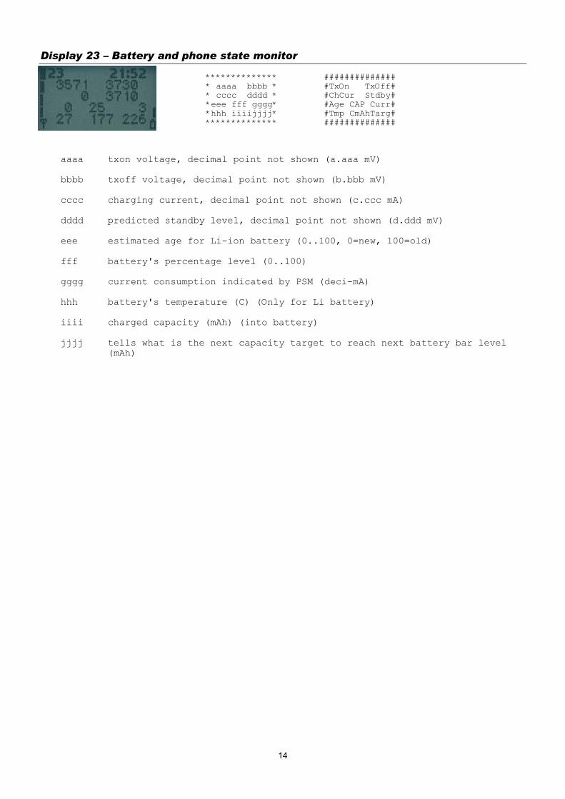
Display 23 – Battery and phone state monitor ************** ############## * aaaa bbbb * #TxOn TxOff# * cccc dddd * #ChCur Stdby# *eee fff gggg* #Age CAP Curr# *hhh iiiijjjj* #Tmp CmAhTarg# ************** ##############
aaaa txon voltage, decimal point not shown (a.aaa mV) bbbb txoff voltage, decimal point not shown (b.bbb mV) cccc charging current, decimal point not shown (c.ccc mA) dddd predicted standby level, decimal point not shown (d.ddd mV) eee estimated age for Li-ion battery (0..100, 0=new, 100=old) fff battery's percentage level (0..100) gggg current consumption indicated by PSM (deci-mA) hhh battery's temperature (C) (Only for Li battery) iiii charged capacity (mAh) (into battery) jjjj tells what is the next capacity target to reach next battery bar level
(mAh)
14
Display 30 – Audio API register display ************** ############## * aaaa bbbb * #A1Cnf A2Cnf# * cccc dddd * # ST AU3 # * eeee ffff * #1Tone 2Tone# * gggg hhhh * # Conf HFVol# ************** ##############
aaaa API_AUD1_CTRL bbbb API_AUD2_CTRL cccc API_SIDETONE dddd API_AU3 eeee API_1_TONE ffff API_2_TONE gggg API_CONFIG hhhh API_HF_VOL
Display 34 – FBUS display ************** ############## *aaaaaa - * #CM LD LM NM # *bbbbbbb- a -* #PEC FEC OEC # *cc * #ACC RXS TXS # *H-- * #Mod # ************** ##############
aa current fbus media in hex bb last sender dev in hex cc last sender media in hex dd Next media to be connected. Same as aa if the connection is not pending. eee fbus parity error counter fff fbus framing error counter ggg fbus overrun error counter hhh fbus alive check counter iii RX Sequence number jjj TX Sequence number k Phone mode: S=slave, H=host
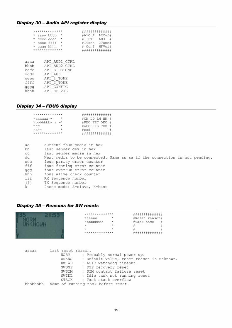
Display 35 – Reasons for SW resets ************** ############## *aaaaa * #Reset reason# *bbbbbbbb * #Task name # * * # # * * # # ************** ##############
aaaaa last reset reason. NORM : Probably normal power up. UNKNO : Default value, reset reason is unknown. HW WD : ASIC watchdog timeout. SWDSP : DSP recovery reset SWSIM : SIM contact failure reset SWIDL : Idle task not running reset STACK : Task stack overflow
bbbbbbbb Name of running task before reset.
15
Display 36 – Counters for resets ++++++++++++++ + aa bb cc + + dd ee ff + + + + + ++++++++++++++
aa Unknown resets bb ASIC watchdog resets cc DSP recovery resets dd SIM contact failure resets ee Idle task not running resets ff Task stack overflow resets
Display 38 – Memory dump
aaaa.... hex dump of 24 successive memory locations
The start address of the dump is entered as 6 digit address value into SIM alpha memory location #30.
An example: address 0x0C89AB -> enter 'name' 0C2089AB into SIM alpha memory location #30.
Dump address is changed only when field test display #38 is selected via menu, changing memory location #30 is not enough!
This display will not be included in offial software, but designers can use it for their own test purposes. Display can be switched on by defining flag DEV_FT_MEMORY_DUMP_IN_USE in ftd_conf.h.
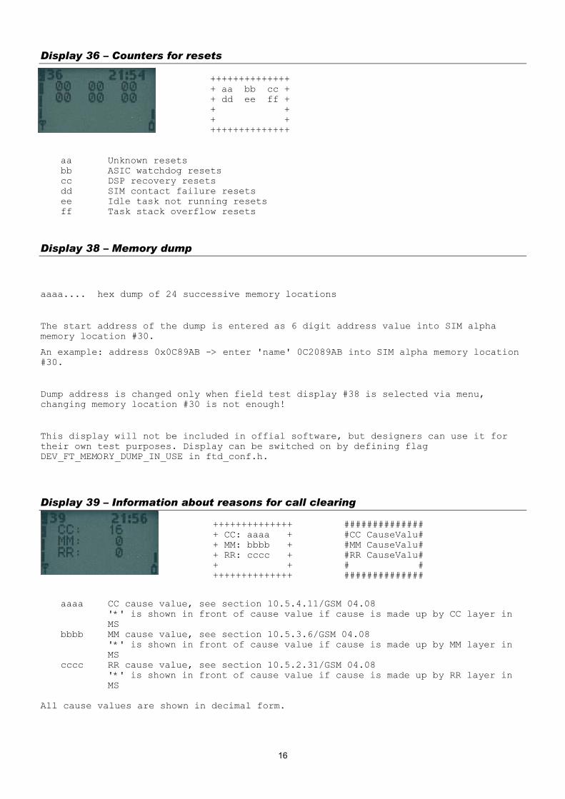
Display 39 – Information about reasons for call clearing ++++++++++++++ ############## + CC: aaaa + #CC CauseValu# + MM: bbbb + #MM CauseValu# + RR: cccc + #RR CauseValu# + + # # ++++++++++++++ ##############
aaaa CC cause value, see section 10.5.4.11/GSM 04.08 '*' is shown in front of cause value if cause is made up by CC layer in MS
bbbb MM cause value, see section 10.5.3.6/GSM 04.08 '*' is shown in front of cause value if cause is made up by MM layer in MS
cccc RR cause value, see section 10.5.2.31/GSM 04.08 '*' is shown in front of cause value if cause is made up by RR layer in MS
All cause values are shown in decimal form.
16
Display 40 – Reset handover counters ************** ############## * RESET * # Use menu # * HANDOVER * # to reset # * COUNTERS * # handover # * * # counters # ************** ############## With this display all timers of the handover display can be reset.
Display 41 (in singleband phones) – Handover display ++++++++++++++ ############## +HandOOK: aaa+ #HandOvOKCntr# +PrevCh : bbb+ #PrevChanCntr# +HONotOK: ccc+ #HandOvNOKCnt# +HOIntra: ddd+ #HOIntraOKCnt# ++++++++++++++ ##############
aaa counter for successful handovers (max. amount 999) bbb counter for successful back to previous channel attempts ccc counter for failed handovers ddd counter for successful intracell handovers or assignments
(max. amount 999) Counters will stop when they reach their maximum. To initialize the counters to zero, select display 40. Display 60 also initializes these counters.
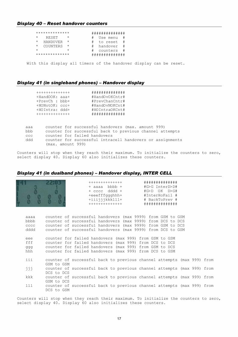
Display 41 (in dualband phones) – Handover display, INTER CELL ++++++++++++++ ############## + aaaa bbbb + #G>G InterD>D# + cccc dddd + #G>D OK D>G# +eeefffggghhh+ #InterHoFail # +iiijjjkkklll+ # BackToPrev # ++++++++++++++ ##############
aaaa counter of successful handovers (max 9999) from GSM to GSM bbbb counter of successful handovers (max 9999) from DCS to DCS cccc counter of successful handovers (max 9999) from GSM to DCS dddd counter of successful handovers (max 9999) from DCS to GSM eee counter for failed handovers (max 999) from GSM to GSM fff counter for failed handovers (max 999) from DCS to DCS ggg counter for failed handovers (max 999) from GSM to DCS hhh counter for failed handovers (max 999) from DCS to GSM iii counter of successful back to previous channel attempts (max 999) from
GSM to GSM jjj counter of successful back to previous channel attempts (max 999) from
DCS to DCS kkk counter of successful back to previous channel attempts (max 999) from
GSM to DCS lll counter of successful back to previous channel attempts (max 999) from
DCS to GSM Counters will stop when they reach their maximum. To initialize the counters to zero, select display 40. Display 60 also initializes these counters.
17
Display 42 (***in dualband phones) – Handover display, INTRA CELL ++++++++++++++ ############## + aaaa bbbb + #G>G IntraD>D# + cccc dddd + #G>D OK D>G# +eeefffggghhh+ #IntraHoFail # +iiijjjkkklll+ # BackToPrev # ++++++++++++++ ##############
aaa counter of successful INTRA CELL handovers (max 9999) from GSM to GSM bbb counter of successful INTRA CELL handovers (max 9999) from DCS to DCS ccc counter of successful INTRA CELL handovers (max 9999) from GSM to DCS ddd counter of successful INTRA CELL handovers (max 9999) from DCS to GSM eee counter of failed INTRA CELL handovers (max 999) from GSM to GSM fff counter of failed INTRA CELL handovers (max 999) from DCS to DCS ggg counter of failed INTRA CELL handovers (max 999) from GSM to DCS hhh counter of failed INTRA CELL handovers (max 999) from DCS to GSM iii counter of successful back to previous normal INTRA CELL channel attempts
(max 999) from GSM to GSM jjj counter of successful back to previous normal INTRA CELL channel attempts
(max 999) from DCS to DCS kkk counter of successful back to previous normal INTRA CELL channel attempts
(max 999) from GSM to DCS lll counter of successful back to previous normal INTRA CELL channel attempts
(max 999) from DCS to GSM Counters will stop when they reach their maximum. To initialize the counters to zero, select display 40. Also display 60 initializes these counters.
Display 43 L2 display
++++++++++++++ ############## +T200MS :aaaa+ #T200 MS GSM # +T200BS :bbbb+ #T200 BS GSM # +T200MS :cccc+ #T200 MS DCS # +T200BS :dddd+ #T200 BS DCS # ++++++++++++++ ##############
aaaa GSM: Counts how many times T200 in MS has expired and therefore L2
transmission has been repeated. bbbb GSM: Counts how many times T200 in BS (network) has expired and therefore
L2 transmission has been repeated. cccc DCS: Counts how many times T200 in MS has expired and therefore L2
transmission has been repeated. (for dualband phones) dddd DCS: Counts how many times T200 in BS (network) has expired and therefore
L2 transmission has been repeated. (for dualband phones) Counters will stop when they reach their maximum. To initialize the counters to zero, select display 40. Display 60 also initializes these counters.
18
Display 44 – Toggle revision level When selected, changes the value of Revision Level from 0 to 1 and vice versa. ************** ************** * * * * * REVISION * * REVISION * *LEVEL IS 00 * *LEVEL IS 01 * * * * * ************** ************** HELP display: ############## #Use menu to # # change # # Revision # # Level # ##############
Display 45 – Toggle transmitter functionality When selected, disables transmitter functionality if enabled and vice versa. New setting is valid until next power off or until new execute of this display. ************** * * *TRANSMITTER * * XXXXXXXX * XXXXXXXX ENABLED or DISABLED * * ************** This FTD can be used to simulate easily situations when the MS can hear the network (i.e. receiving signal is good enough), but the network can not receive any messages from the MS. Location updating attempts or MO call establishment attempts can be failed (random access failure) by this FTD and field testing of these failures is much easier now. Next periodic location updating can be checked from the display 10 (chapter 3.1.10) by taking the difference of current T3212 counter value and T3212 timeout value. HELP display: ############## #Use menu to # # enable or # # disable # #transmitter # ##############
19

Display 51 – SIM information ++++++++++++++ Example display: ++++++++++++++ +aaa bbb ccc + +3/5 64 YES + + dddddddd + +DOWN(UP) + + f g hh ii + + 3 2 9 10 + + j kkkk + + 2 FE01 + ++++++++++++++ ++++++++++++++
aaa Sim voltage selection type (5, 3 or 3/5) bbb Sim baudrate (372, 64, 32 or 0) ccc Clock stop allowed, Yes or No dddd Clock stop condition, Up or down (preferred) eee Clock stopped, Yes or No (NOT IMPLEMENTED) f pin1 attempts left (0,1,2,3) g pin2 attempts left (0,1,2,3) hh puk1 attempts left (0-10) ii puk2 attempts left (0-10) j ATR retransmission counter (0-9) kkkk Transmission frame/parity errors, FE/PE + hexadecimal count
HELP display: ############## #VSel Bau SAl# #SCond CStop# #PIN12 PUK12# # ATR FE/PE # ##############
Display 54 – Block display 1 ++++++++++++++ ############## +aa bb aa bb+ #ResF1 ResF2# +aa bb aa bb+ #ResF3 ResF4# +aa bb aa bb+ #ResF5 ResF6# +aa bb aa bb+ #ResF7 ResF8# ++++++++++++++ ##############
1. row: Block set 1, block set 2 2. row: Block set 3, block set 4 3. row: Block set 5, block set 6 4. row: Block set 7, block set 8 aa Number of reserved blocks bb Number of free blocks in worst case
Display 55 – Block display 2 ++++++++++++++ ############## +aa bb aa bb+ #ResF9 ResF10# +aa bb aa bb+ #ResF11ResF12# +aa bb aa bb+ #ResF13ResF14# +aa bb aa bb+ #ResF15ResF16# ++++++++++++++ ##############
1. row: Block set 9, block set 10 2. row: Block set 11, block set 12 3. row: Block set 13, block set 14 4. row: Block set 15, block set 16 aa Number of reserved blocks
20

bb Number of free blocks in worst case
21

Display 56 – Block display 3 ++++++++++++++ ############## + aaaaaa bbb + # Ptr Cntr # + cccccccc + # Task # + + # # + + # # ++++++++++++++ ##############
aaaaaa Pointer to memory where double deallocation was called, in hex format. bbb Counter for failed deallocations. cccccccc Name of task which last tried to double deallocate a block.
Note: This display is only valid when the counter for failed deallocations is not zero.
Display 57 – Memory status before reset ++++++++++++++ ############## +aaaaaaaaaaaa+ # Status of # +aaaaa... + # stacks # +bbbbbbbb + # Block sets # + + # # ++++++++++++++ ##############
aaaaaa Status of each stack before reset. First position contains the status of stack 0, second position the status of stack 1 and so on. The last position contains the status of System stack. Number of stacks depends on the current configuration of SW. Possible values for each stack are:
0 : status OK, no overflow 1 : status not OK, stack overflow,
bbbbbbb Status of each block set before reset. First position contains the
status of block set 1, second position the status of block set 2 and so on. Possible values for each block set are:
0 : status OK 1 : block set full 2 : (de)allocation error or total memory corruption
Note: This display is only valid when a unknown or a stack overflow interrupt has occured.
22

Display 60 – Reset counters to zero ************** ############## * FIELD TEST * #Use menu to # * DISPLAY * #reset field # * COUNTERS * #test display# * RESET * # counters # ************** ##############
With this display all counters of the field test display can be reset (i.e. all counters in 40 and 60 series).
Display 61 – Search and reselection counter display ++++++++++++++ ############## +NOPSW :aaaa+ #PSWMesgCntr # +SYNCR :bbbb+ #SyncMeasCntr# +RESELEC:cccc+ #CellReselCtr# + + # # ++++++++++++++ ##############
aaaa counter for MDI_NO_PSW_FOUND message received from DSP in hexadecimal
form. bbbb counter for synchronization measurement attempts in decimal form. If
counter value is over 9999 then four x are shown. cccc counter for cell reselections in hexadecimal form.
On poweroff the values of the counter displays are stored onto the EEPROM, where they will be read during power on. To initialize the counters to zero, select display 60. These counters are automatically reset to zero when they exceed their maximum value.
23
Display 61 (dualband) – Search and reselection counter display ++++++++++++++ ############## +aaaaa bbbbb+ #NOPswGSM DCS# +ccccc ddddd+ #Sync GSM DCS# +eeeee fffff+ #reselG>G D>D# +ggggg hhhhh+ #reselG>D D>G# ++++++++++++++ ##############
aaaaa GSM counter for MDI_NO_PSW_FOUND message received from DSP in decimal form (max 99999).
bbbbb DCS counter for MDI_NO_PSW_FOUND message received from DSP in decimal form (max 99999).
ccccc GSM counter for synchronization measurement attempts in decimal form. If counter value is over 99999 then five x are shown.
ddddd DCS counter for synchronization measurement attempts in decimal form. If counter value is over 99999 then five x are shown.
eeeee counter for GSM->GSM cell reselections in decimal form (max 99999). fffff counter for DCS->DCS cell reselections in decimal form (max 99999). ggggg counter for GSM->DCS cell reselections in decimal form (max 99999). hhhhh counter for DCS->GSM cell reselections in decimal form (max 99999).
On power off the values of the counter displays are stored onto the EEPROM, where they will be read during power on. To initialize the counters to zero, select display 60. Counters are automatically reset to zero when they exceed their maximum value.
Display 62 – Neighbour measurement counter display ++++++++++++++ ############## + PSW :aaaa + #NeghbrPSWCtr# + SYNCR:bbbb + #SyncMeasCntr# + BCCH :cccc + #BCCHMeasAtmp# + BCCHE:dddd + #BCCHExtMeAtm# ++++++++++++++ ##############
aaaa counter for neighbour PSW measurement attempts bbbb counter for neighbour synchronization measurement attempts cccc counter for neighbour BCCH measurement attempts dddd counter for neighbour BCCH Ext measurement attempts
Counter values are shown in hexadecimal form. On poweroff the values of the counter displays are stored onto the EEPROM, where they will be read during power on. To initialize the counters to zero, select display 60. Counters are automatically reset to zero when they exceed their maximum value.
24
Display 63 – Call attempts counters ++++++++++++++ ############## + aa bb + #CalRel RelDi# + ccc ddd + #MOCAtmp MOOK# + eee fff + #AllMT MTOK# + + # # ++++++++++++++ ##############
aa Reason of last call release
Cause from messages disconnect and release complete. Refer to ETSI GSM 04.08 for further explanation.
bb Direction of last call release UN : Unknown MO : Mobile originated MT : Mobile terminated IN : Internal (ME CS sw)
ccc count of all MO call attempts made ddd count of succeeded MO calls eee count of all call setups received fff count of succeeded MT calls
On poweroff the values of the counter displays are stored onto the EEPROM, where they will be read during power on. To initialize the counters to zero, select display 60. Counters are automatically reset to zero when they exceed their maximum value.
Display 64 – Location Update attempts counters ++++++++++++++ ############## + aa bbb ccc + #Nfai NL NLOK# + dd eee fff + #PFai PL PLOK# + + # Loc update # + + # counters # ++++++++++++++ ##############
aa Reason of last normal location update failure bbb count of normal location update attempts ccc count of succeeded normal location updates dd Reason of last periodic or IMSI attach location update failure eee count of all periodic and IMSI attach location update attempts fff count of succeeded periodic and IMSI attach location updates
On poweroff the values of the counter displays are stored onto the EEPROM, where they will be read during power on. To initialize the counters to zero, select display 60. Counters are automatically reset to zero when they exceed their maximum value.
25
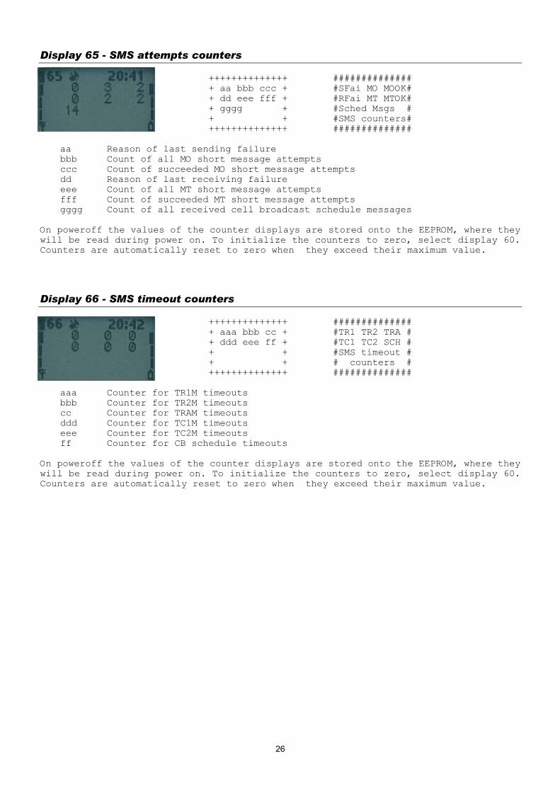
Display 65 - SMS attempts counters ++++++++++++++ ############## + aa bbb ccc + #SFai MO MOOK# + dd eee fff + #RFai MT MTOK# + gggg + #Sched Msgs # + + #SMS counters# ++++++++++++++ ##############
aa Reason of last sending failure bbb Count of all MO short message attempts ccc Count of succeeded MO short message attempts dd Reason of last receiving failure eee Count of all MT short message attempts fff Count of succeeded MT short message attempts gggg Count of all received cell broadcast schedule messages
On poweroff the values of the counter displays are stored onto the EEPROM, where they will be read during power on. To initialize the counters to zero, select display 60. Counters are automatically reset to zero when they exceed their maximum value.
Display 66 - SMS timeout counters ++++++++++++++ ############## + aaa bbb cc + #TR1 TR2 TRA # + ddd eee ff + #TC1 TC2 SCH # + + #SMS timeout # + + # counters # ++++++++++++++ ##############
aaa Counter for TR1M timeouts bbb Counter for TR2M timeouts cc Counter for TRAM timeouts ddd Counter for TC1M timeouts eee Counter for TC2M timeouts ff Counter for CB schedule timeouts
On poweroff the values of the counter displays are stored onto the EEPROM, where they will be read during power on. To initialize the counters to zero, select display 60. Counters are automatically reset to zero when they exceed their maximum value.
26
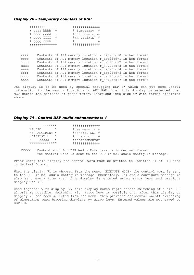
Display 70 - Temporary counters of DSP ++++++++++++++ ############## + aaaa bbbb + # Temporary # + cccc dddd + #DSP counters# + eeee ffff + #(R DSP2FTD) # + gggg hhhh + # # ++++++++++++++ ##############
aaaa Contents of API memory location r_dsp2ftd+0 in hex format bbbb Contents of API memory location r_dsp2ftd+1 in hex format cccc Contents of API memory location r_dsp2ftd+2 in hex format dddd Contents of API memory location r_dsp2ftd+3 in hex format eeee Contents of API memory location r_dsp2ftd+4 in hex format ffff Contents of API memory location r_dsp2ftd+5 in hex format gggg Contents of API memory location r_dsp2ftd+6 in hex format hhhh Contents of API memory location r_dsp2ftd+7 in hex format
The display is to be used by special debugging DSP SW which can put some useful information to the memory locations on API RAM. When this display is selected then MCU copies the contents of those memory locations into display with format specified above.
Display 71 - Control DSP audio enhancements 1 ************** ############## *AUDIO * #Use menu to # *ENHANCEMENT * #control DSP # *DISPLAY 1 * # audio # * XXXXX * #enhancements# ************** ##############
XXXXX Control word for DSP Audio Enhancements in decimal format. The control word is sent to the DSP in mdi audio configure message.
Prior using this display the control word must be written to location 31 of SIM-card in decimal format. When the display 71 is choosen from the menu, (EXECUTE MODE) the control word is sent to the DSP in mdi audio configure message immediately. Mdi audio configure message is also sent every time when this display is entered using arrow keys and previous display was 72. Used together with display 72, this display makes rapid on/off switching of audio DSP algorithms possible. Switching with arrow keys is possible only after this display or display 72 has been selected from the menu. This prevents accidental on/off switching of algorithms when browsing displays by arrow keys. Entered values are not saved to EEPROM.
27
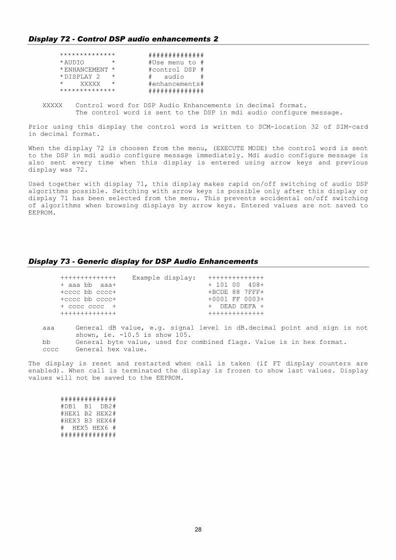
Display 72 - Control DSP audio enhancements 2 ************** ############## *AUDIO * #Use menu to # *ENHANCEMENT * #control DSP # *DISPLAY 2 * # audio # * XXXXX * #enhancements# ************** ##############
XXXXX Control word for DSP Audio Enhancements in decimal format. The control word is sent to the DSP in mdi audio configure message.
Prior using this display the control word is written to SCM-location 32 of SIM-card in decimal format. When the display 72 is choosen from the menu, (EXECUTE MODE) the control word is sent to the DSP in mdi audio configure message immediately. Mdi audio configure message is also sent every time when this display is entered using arrow keys and previous display was 72. Used together with display 71, this display makes rapid on/off switching of audio DSP algorithms possible. Switching with arrow keys is possible only after this display or display 71 has been selected from the menu. This prevents accidental on/off switching of algorithms when browsing displays by arrow keys. Entered values are not saved to EEPROM.
Display 73 - Generic display for DSP Audio Enhancements ++++++++++++++ Example display: ++++++++++++++ + aaa bb aaa+ + 101 00 408+ +cccc bb cccc+ +BCDE 88 7FFF+ +cccc bb cccc+ +0001 FF 0003+ + cccc cccc + + DEAD DEFA + ++++++++++++++ ++++++++++++++
aaa General dB value, e.g. signal level in dB.decimal point and sign is not shown, ie. -10.5 is show 105.
bb General byte value, used for combined flags. Value is in hex format. cccc General hex value.
The display is reset and restarted when call is taken (if FT display counters are enabled). When call is terminated the display is frozen to show last values. Display values will not be saved to the EEPROM. ############## #DB1 B1 DB2# #HEX1 B2 HEX2# #HEX3 B3 HEX4# # HEX5 HEX6 # ##############
28

Display 74 - DSP audio enhancements 1 (DRC) ++++++++++++++ Example display: ++++++++++++++ + aaa bbb + + 101 408 + + ccc + + 480 + + dd ee + + 01 03 + + + + + ++++++++++++++ ++++++++++++++
aaa Downlink signal level in dB, calculated using DRC level measuring block. Decimal point and sign is not shown, ie. -10.5 is show 105.
bbb Uplink signal level in dB, calculated using DRC level measuring block. Decimal point and sign is not shown, ie. -10.5 is show 105.
ccc Background noise signal level in dB, calculated using DRC level measuring block, decimal point and sign is not shown, ie. -10.5 is show 105.
dd Downlink DRC table value, shown in decimal integer, two digits. ee Uplink DRC table value, decimal integer, two digits.
The display is reset and restarted when call is taken (if FT display counters are enabled). When call is terminated the display is frozen to show last values. Display values will not be saved to the EEPROM. ############## #DSigL USigL # # NseLvl# # DTbl UTbl # # # ##############
Display 75 - Audio path status ++++++++++++++ ############## +Mod:aaaaaaaa+ #ExtAudStatus# +AudReq: bbbb+ #AudioRequest# +AccMod: cccc+ #AccessoryMod# +H2Path: dd + #HFU2Path # ++++++++++++++ ##############
aaaaa external audio status, values are: HP, HF, HEADSET, EXT and HP_OFFHO bbbb audio_request bitmap in hex, contents (masks) are specified in AUD_DATA.H cccc Accessory audio mode dd HFU-2 path
29

Display 76 - Ear (= downlink) audio display ++++++++++++++ Example display: ++++++++++++++ + Vaa Pbbb + + V0A P125 + + Cccc CAddd + + C000 CA001 + +PAeee + +PA353 + + + + + ++++++++++++++ ++++++++++++++
aa Volume level. bbb Peak value of downlink audio signal during last frame in dB, decimal
point and sign is not shown, ie. -10.5 is show 105. ccc Cut off counter value of last frame. This counter counts how many samples
are saturated during last frame. ddd Moving average of cut off counter, decimal point and sign is not shown,
ie. -10.5 is show 105. eee Moving average of peak levels.
The display is reset and restarted when call is taken (if FT display counters are enabled). When call is terminated the display is frozen to show last values. Display values will not be saved to the EEPROM. ############## #EVol PeakVal# #CutOff COAve# #PkAver # # # ##############
Display 77 - Microphone (= uplink) audio display ++++++++++++++ Example display: ++++++++++++++ + Paaa Abbb + + P303 A225 + + Cccc CAddd + + C023 CA003 + + + + + + + + + ++++++++++++++ ++++++++++++++
aaa Peak value of uplink audio signal during last frame in dB decimal point and sign is not shown, ie. -10.5 is show 105.
bbb Moving average of peak levels, decimal point and sign is not shown, ie. -10.5 is show 105.
ccc Cut off counter value of last frame. This counter counts how many samples are saturated during last frame.
ddd Moving average of cut off counter The display is reset and restarted when call is taken (if FT display counters are enabled). When call is terminated the display is frozen to show last values. Display values will not be saved to the EEPROM. ############## #MicPeak MAve# #CutOff COAve# # # # # ##############
30
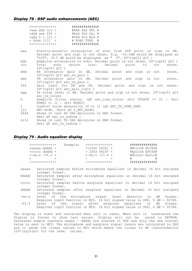
Display 78 - DSP audio enhancements (AEC) ++++++++++++++ ############## +aaa bbb ccc + #EAA Ada ERL # +ddd eee fff + #RxG TxG GLi # +ggg h i jjj + #TxN Sta Mod # + kkkk llll + # RVAD TVAD # ++++++++++++++ ##############
aaa Electro-acoustic attenuation of echo from DSP point of view in dB. Decimal point and sign is not shown. E.g. -10.5dB would be displayed as "105", -0.5 dB would be displayed as " 5". 20*log10( Q15 )
bbb Adaptive attenuation of echo. Decimal point is not shown. 20*log10( Q15 ) ccc Total echo return loss. Decimal point is not shown.
20*log10( Q15 ) ddd RX attenuator gain in dB. Decimal point and sign is not shown.
20*log10( Q15 aec_rx_gain ) eee TX attenuator gain in dB. Decimal point and sign is not shown.
20*log10( Q15 aec_tx_gain ) fff Gain limit for RX and TX. Decimal point and sign is not shown.
20*log10( Q15 aec_gain_limit ) ggg Tx noise level in dB. Decimal point and sign is not shown. 20*log10( Q15
aec_tx_noise) h Adaptive filter status. (Q0 aec_nlms_state) (bit UPDATE << 2) | (bit
NLMS2 << 1) | (bit NLMS1) I Comfort noise generation (0 or 1) (Q0 AEC_TX_COMF_GEN) jjj AEC mode. (byte Q0 s_AEC_mode) kkkk Shows 16 last RX VAD decisions in HEX format.
Hex( Q0 aec_rx_vadreg ) Llll Shows 16 last TX VAD decisions in HEX format.
Hex( Q0 aec_tx_vadreg )
Display 79 - Audio equalizer display ++++++++++++++ Example: ++++++++++++++ ############## +aaaaa bbbbb + +12345 54321 + #MiCutB MiCTA# +ccccc ddddd + + 2353 46187 + #EpCutB EPCTA# +-ee.e -ff.f + +-46.5 -27.4 + #MicLev EarLv# + + + + # # ++++++++++++++ ++++++++++++++ ##############
aaaaa Saturated samples before microphone equalizer in decimal 16 bit unsigned integer format.
bbbbb Saturated samples after microphone equalizer in decimal 16 bit unsigned integer format.
ccccc Saturated samples before earpiece equalizer in decimal 16 bit unsigned integer format.
ddddd Saturated samples after earpiece equalizer in decimal 16 bit unsigned integer format.
-ee.e Level of the microphone signal level detector in dB format. Requires log10 function in MCU. 16 bit signed value in DSP, 0 dB = 32768.
-ff.f Level of the signal after earpiece equalizer in dB format. Requires log10 function in MCU. 16 bit signed value in DSP, 0 dB = 32768.
The display is reset and restarted when call is taken. When call is terminated the display is frozen to show last values. Display will not be saved to EEPROM. Saturated sample counters aaaaa - ddddd are counted in DSP and only the new counter value is sent to MCU. The microphone and earpiece signal levels are calculated in DSP and it sends the linear values to MCU which makes the linear to dB transformation (20*log10(x)) for the level values.
31

Display 80 - Reset and restart timers ************** ############## * * # Use menu # * TIMERS * # to reset # * RESET * # field test # * * # timers # ************** ##############
With this display all timers of the display 82 can be reset. These timers will be automatically reset after the battery has been fullycharged and the charger is disconnected. Thus it's not always necessary to use the display 80.
Display 81 - Enable or disable timers ************** * * * TIMERS * * XXXXXXXX * XXXXXXXX ENABLED or DISABLED * * **************
This display will start or stop the timers. On power off the values of the timer displays are stored onto the EEPROM, where they will be read during power on. To initialize the counters to zero, use display 80. Timers will be automatically disabled when recharge battery message is reached. Also the current state of timer disabling/enabling is stored onto the EEPROM. ############## #Use menu to # #control test# # display # # timers # ##############
32

Display 82 - Test timer display ++++++++++++++ ############## +aaaaa bbbbb + #PwrOn InServ# +ccccc ddddd + #NSPS TxON # + TIMERS eee + # Timers # + + # Status # ++++++++++++++ ##############
aaaaa timer for how long the phone has been powered on bbbbb timer for how long the phone has been in service ccccc timer for NO-SERV POWER-SAVE state ddddd timer for how long the transmitter has been on eee state of timers, ON/OFF
All the values are shown in one minute resolution. The accuracy of the timers is about one second. The display uses following format for timers: HHHMM where HHH is hours and MM is minutes. All timers of this display will be reset if the charger is disconnected from the mobile with fully charged battery. The maximum value of the timers is 99 h 59 min. When 'powered on' timer has reached value 9959, all timers will be stopped. NOTE: When the maxium usage time of the phone is required (e.g. idle time measurement) then ALL field test displays must be deactivated!
Display 83 - Control of task information displays ************** * * * SHOW TASK * * XXXXXXXXX * XXXXXXXXX is "STACKS", "MSG BUFS" or "FAST BUFS" * * ************** Shows what information about tasks is currently shown in displays 84 - 87. To select the type of information select this display via menu. Type is changed in order STACKS -> MSG BUFS -> FAST BUFS -> STACKS. So, if STACKS is currently displayed and you want to see FAST BUFS, you have to select this display twice via menu.
"STACKS" shows free stack space in worst case. "MSG BUFS" shows the peak number of pending messages. "FAST BUFS" shows the peak number of pending fast messages.
############## #Use menu to # #select shown# # task info # # # ##############
33

Display 84 - Information of task numbers 0 - 7 ++++++++++++++ + aaaa bbbb + + cccc dddd + + eeee ffff + + gggg hhhh + ++++++++++++++
aaaa task 0 bbbb task 1 cccc task 2 dddd task 3 eeee task 4 ffff task 5 gggg task 6 hhhh task 7
Numbers tell how many stack memory locations have been empty in the worst case. So, if number is zero, stack has been full.
Values are not stored to EEPROM. Task names are listed on help display.
Display 85 - Information of task numbers 8 - 15 ++++++++++++++ + aaaa bbbb + + cccc dddd + + eeee ffff + + gggg hhhh + ++++++++++++++
aaaa task 8 bbbb task 9 cccc task 10 dddd task 11 eeee task 12 ffff task 13 gggg task 14 hhhh task 15
Values are not stored to EEPROM. Task names are listed on help display.
34

Display 86 - Information of task numbers 16 - 23 ++++++++++++++ + aaaa bbbb + + cccc dddd + + eeee ffff + + + ++++++++++++++
aaaa task 16 bbbb task 17 cccc task 18 dddd task 19 eeee task 20 ffff task 21 gggg task 22 hhhh task 23
Values are not stored to EEPROM. Task names are listed on help display.
Display 87 - Information of OS_SYSTEM_STACK ++++++++++++++ ############## + aaaa bbbb + # FIQ IRQ # + + # # + + # # + + # # ++++++++++++++ ##############
aaaa OS_SYSTEM_STACK Values are not stored to EEPROM.
Display 88 - Information of the current MCU and DSP software versions ************** ############## *aaaaa bbbbbb* #MCUSW PPM # *Date cccccc* #MCUSW_Date # *ChkSum dddd * #MCU_Checksum# *eeeeeeeeeeee* #DSP_Version # ************** ##############
aaaaa version number of MCU SW (e.g. 5.02) bbbbbb PPM version (e.g. 5.02A) cccccc date of version.c (e.g. 990102 means 02. January 1999) dddd MCU SW checksum eeeeeeeeeeee version of DSP software
Display 89 - Information of the current Hw and TXT versions ************** ############## *HW: aaaa * #HW Version # *TXT:bbbbbbb * #Text Version# * * # # * * # # ************** ##############
aaaaa Hardware version (e.g. 2350) bbbbbb Text version (e.g. U190199)
35

36
[email protected] -----BEGIN PGP PUBLIC KEY BLOCK----- Version: PGPfreeware 6.0.2i mQGiBDbfqukRBADIfexLK1MqpvwWjAFmNzKADCvb4wY1SFJUezJrgGnHQRfURnH+ u9ucAB56o1b/b2rsdrEjR7xL86YMn/31XtCUae/PLfzgoFUcIcyu4TTkQfeRP/WH l3KKU1kDNKeKS1EgEPIwehEpgNtKpn9OaAodIo2IrlCVnjqaKLDhPHf4JQCg/3d0 +eIvZ7PK7o0aNNQNEB2B6b0D/24+rHGtPkN9rA71bJ6Wjc+aJh0E+koSdowFlWnT QaJPYx/sEMyFQZTT22aVgcAKxfeWmG8mjqCjz/joP6f8CrHjNgIP6/uoNehS2PD9 33urfHuTQyiNhAtfTga3rxL9WAnIb7qD6vFcfKfkPvx1r2i/2JAIxQtCVyZcb+Em U0MIA/9Xa2Xe5VY+3NLycUGGMLB+CEjiOILWtlkZ7x15JhHHWrvqgvAUjAKI6uB7 XtgkYL0ZFlvjfIaIrd1Gg2UiKjFErP2+2SvIRW4FqeI90wXc32u93EQ9OdmNvD1c FiJCIa1DzbPnSAg1NJfOrAryHVanv4C3SmF/uGpWCZiu6YOGgbQXRmxpcE8gPGZs aXBvQGd5cmFsLmNvbT6JAEsEEBECAAsFAjbfqukECwMCAQAKCRAwMxvYafoMXlq8 AJ4qXfgO7uOtsasUDSWogbCilTjmKgCgj7mnOMY4PhpkyoHTQnvIarfb4di5Ag0E Nt+q6RAIAPZCV7cIfwgXcqK61qlC8wXo+VMROU+28W65Szgg2gGnVqMU6Y9AVfPQ B8bLQ6mUrfdMZIZJ+AyDvWXpF9Sh01D49Vlf3HZSTz09jdvOmeFXklnN/biudE/F /Ha8g8VHMGHOfMlm/xX5u/2RXscBqtNbno2gpXI61Brwv0YAWCvl9Ij9WE5J280g tJ3kkQc2azNsOA1FHQ98iLMcfFstjvbzySPAQ/ClWxiNjrtVjLhdONM0/XwXV0Oj HRhs3jMhLLUq/zzhsSlAGBGNfISnCnLWhsQDGcgHKXrKlQzZlp+r0ApQmwJG0wg9 ZqRdQZ+cfL2JSyIZJrqrol7DVekyCzsAAgIH+QG2NtWgB8NDQsIJfShr1F8naaM+ xyM3SwhCAyYrXiiMySIeUx07An/BN3H57qHBZXwU0w+lHo7C2xOIILLXveRq1Xhr Rpi/RaQU9sHmetpCx6CpBRwRwx1hGJ4TOxRZ/9RwdiEG5xlQqY11T4mUI0bqCk4y 6+EcY4ps16egr7TUm9aNW6JoqRXBCoFacoQuJx9EOlvk/tROZCKV9TxCx478fn6i rWP6bgun23+WlAU34RrS3oMAaN7TvUntYzp6br8x80Klk45iydmJSuROUqRHLeIe eAct8cvqzFK2o9ta+kw5j7h0shxyzyyvRAlH5uVpJp0oGokwwy1N3mDecySJAEYE GBECAAYFAjbfqukACgkQMDMb2Gn6DF5RHQCeNSBR763t/QOmGSPSoCkm8Ut3gvgA njhf6FOTPe27KFwECymc1SVLO5GK =bMMm -----END PGP PUBLIC KEY BLOCK-----