Nokia VPN Appliance - NIST
40
© Copyright 2005, 2006 Nokia This document may be freely reproduced and distributed whole and intact including this Copyright Notice. Nokia VPN Appliance FIPS 140-2 Cryptographic Module Security Policy Level 2 Validation Version 2.0 October 2006 Module Hardware Versions: IP350, IP355, IP380, IP385 Software Versions: IPSO v3.7.99 with Check Point VPN-1 NG with Application Intelligence (R54) IPSO v3.9 with Check Point VPN-1 NGX (R60) [HFA-03]
Transcript of Nokia VPN Appliance - NIST

© Copyright 2005, 2006 Nokia This document may be freely reproduced and distributed whole and intact including this Copyright Notice.
Nokia VPN Appliance
FIPS 140-2 Cryptographic Module Security Policy Level 2 Validation
Version 2.0 October 2006
Module Hardware Versions:
IP350, IP355, IP380, IP385 Software Versions:
IPSO v3.7.99 with Check Point VPN-1 NG with Application Intelligence (R54) IPSO v3.9 with Check Point VPN-1 NGX (R60) [HFA-03]

© Copyright 2005, 2006 Nokia Page 2 of 40 This document may be freely reproduced and distributed whole and intact including this Copyright Notice.
Table of Contents
1 INTRODUCTION....................................................................................................... 3
1.1 PURPOSE.............................................................................................................. 3 1.2 REFERENCES ........................................................................................................ 3
2 NOKIA VPN APPLIANCE......................................................................................... 4
2.1 OVERVIEW ............................................................................................................ 4 2.2 CRYPTOGRAPHIC MODULE ..................................................................................... 4 2.3 MODULE INTERFACES............................................................................................. 6 2.4 ROLES AND SERVICES............................................................................................ 8
2.4.1 Crypto Officer Role........................................................................................ 8 2.4.2 User Role .................................................................................................... 14 2.4.3 Authentication Mechanisms......................................................................... 14
2.5 ELECTROMECHANICAL INTERFERENCE/COMPATIBILITY (FCC COMPLIANCE) ............. 16 2.6 PHYSICAL SECURITY ............................................................................................ 16 2.7 OPERATIONAL ENVIRONMENT ............................................................................... 16 2.8 CRYPTOGRAPHIC KEY MANAGEMENT .................................................................... 16
2.8.1 Key Generation ........................................................................................... 22 2.8.2 Key Establishment....................................................................................... 22 2.8.3 Key Entry and Output .................................................................................. 22 2.8.4 Key Storage................................................................................................. 22 2.8.5 Key Zeroization ........................................................................................... 22
2.9 SELF-TESTS........................................................................................................ 23 2.10 DESIGN ASSURANCE............................................................................................ 24 2.11 MITIGATION OF OTHER ATTACKS........................................................................... 24
3 SECURE OPERATION (APPROVED MODE)........................................................ 25
3.1 CRYPTO OFFICER GUIDANCE................................................................................ 25 3.1.1 Hardware Setup .......................................................................................... 25 3.1.2 Installing, Upgrading or Downgrading the Module Software........................ 27 3.1.3 Initializing Check Point Modules.................................................................. 29 3.1.4 Setting the Module to FIPS Mode................................................................ 30 3.1.5 Initializing the Remote Management of the Module..................................... 30 3.1.6 Management and Monitoring....................................................................... 32
3.2 USER GUIDANCE ................................................................................................. 37
4 APPENDIX A – DISABLED MECHANISMS........................................................... 38
5 APPENDIX B – ALGORITHM VALIDATION CERTIFICATE NUMBERS .............. 39
6 ACRONYM DEFINITIONS ...................................................................................... 40
© Copyright 2005, 2006 Nokia Page 3 of 40 This document may be freely reproduced and distributed whole and intact including this Copyright Notice.
1 INTRODUCTION 1.1 Purpose
This document is a nonproprietary Cryptographic Module Security Policy for the Nokia IP35x and IP38x VPN Appliance families. This security policy describes how the Nokia VPN Appliances meet the security requirements of FIPS 140-2 and how to run the module in a secure FIPS 140-2 mode. This document was prepared as part of the FIPS 140-2 Level 2 validation of the module.
Hardware versions IP350 and IP380 are previously validated under FIPS 140-2 Certificate #450 supporting the following software configurations:
• IPSO v3.7.99 [build DEV1A] with Check Point VPN-1 Next Generation (NG) with Application Intelligence (AI) (R54)
• IPSO v3.9 [build 045] with Check Point VPN-1 NGX (R60) [HFA-03]
This Security Policy supports a revalidation of the previous Nokia VPN Appliance FIPS 140-2 validation and adds additional hardware models (IP355, IP385) to the list of FIPS 140-2 tested configurations for IPSO 3.9 and Check Point NGX (R60). No cryptographic changes have been made to the software utilized by any of the new hardware being introduced in this Security Policy. The new hardware platforms included in this document simply provide an internal Flash memory drive instead of a hard drive for the storage and execution of the module operating system and application software. The previously-validated hardware versions (IP350, IP380) implement internal hard drives.
The Nokia VPN Appliances are referenced collectively in this document as IP security platforms, security platforms, platforms, and the module(s). Specific differences between module hardware versions are pointed out where relevant.
1.2 References This document deals only with operations and capabilities of the module in the technical terms of a FIPS 140-2 cryptographic module security policy. The Nokia Web site (http://www.nokia.com/) contains information on the full line of products from Nokia.
Additional information regarding the Check Point VPN-1 software that is used inside the Nokia VPN Appliances, including specific configuration instructions for the software can be found by referencing the Check Point VPN-1 FIPS 140-2 security policy, available at the following URL:
http://csrc.nist.gov/cryptval/140-1/140sp/140sp722.pdf

© Copyright 2005, 2006 Nokia Page 4 of 40 This document may be freely reproduced and distributed whole and intact including this Copyright Notice.
2 NOKIA VPN APPLIANCE 2.1 Overview
The Nokia VPN Appliances are IP security platforms designed to provide a secure, reliable, and manageable integrated security solution for secure Internet communication and access control for networks. The security platforms combine the security-hardened operating system, IPSO, with the market-leading Check Point VPN-1 software suite on a purpose-built security hardware platform. As network devices, the Nokia VPN Appliances support a comprehensive suite of IP-routing functions and protocols, including RIPv1/RIPv2, IGRP, OSPF and BGP4 for unicast traffic and DVMRP for multicast traffic.
Some highlighted security features of the Nokia VPN Appliances are:
• Read/write and read-only access modes
• Screening of all incoming communications to ensure authorized user access
• SSH-secured remote management of the modules (IPSO)
• SSHv1 and SSHv2 supported
• TLS-secured remote management of Check Point applications
• Secure VPN between subsystems
• Multiple layers of authentication required when accessing the remote management interface for IPSO
The Nokia VPN Appliances are rack mounted devices that are differenti-ated through their performance levels. The modules are designed to efficiently support real-world, mixed traffic solutions. As VPN platforms, all modules greatly accelerate the embedded Check Point VPN-1/FireWall-1 performance by using the Nokia Firewall Flows. VPN performance is enhanced through the use of hardware cryptographic acceleration. The following chart illustrates the performance differences of the modules covered by this Security Policy:
Model Firewall Speed VPN Speed (AES, TDES) IP350 462Mbps 113Mbps IP355 462Mpbs 113Mbps IP380 1.6Gbps 314Mbps IP385 1.6Gbps 314Mbps
2.2 Cryptographic Module The Nokia VPN Appliances were tested as multi-chip standalone cryptographic modules. Each module’s metal enclosure physically encloses the complete set of hardware and software components, and represents the cryptographic boundary of each module. The cryptographic modules are each 1U full-width rack mount units.

© Copyright 2005, 2006 Nokia Page 5 of 40 This document may be freely reproduced and distributed whole and intact including this Copyright Notice.
All hardware chasses include support for Field Replaceable Unit (FRU) upgrades to internal network interface cards, hard drives (where supported), FLASH memory, and other components (e.g., fans or power supplies replaced with identical parts). In the IP380 and IP385 hardware versions, the installation of an optional factory-installed hardware cryptographic accelerator card causes the hardwired internal accelerator chip to be bypassed. Both accelerator configurations were tested for compliance to FIPS 140-2. All FRU upgrades are performed by the factory or a reseller prior to delivery of the module to the end user. The end-user has no option to service or install these internal components.
The Nokia VPN Appliances run the proprietary Nokia security-hardened operating system, IPSO, along with a binary image of the Check Point VPN-1 cryptographic software for VPN and firewall functionalities.
IPSO and the hardware chassis provides the operational environment upon which the Check Point VPN-1 application binary executes. The following software combination was used for the FIPS 140-2 validation testing covered by this Security Policy:
IPSO v3.9 [build 045] with Check Point VPN-1 NGX (R60) [HFA-03] installed
There are no differences between the hardware or IPSO and Check Point software versions that comprised the previous FIPS 140-2 validations of the modules covered by the original FIPS 140-2 certificate #450 and the present validation testing effort. The only difference between the previous and current FIPS 140-2 validation efforts is the inclusion of additional supported and tested VPN Appliance hardware platforms (IP355 and IP385 in the above software configuration). All module hardware configurations implement an Intel Pentium™ III CPU.
Aside from a series of non-security-relevant bug fixes and performance enhancements, the principal difference between IPSO versions 3.7.99 and 3.9 is that the latter implements support for new features introduced by Check Point VPN-1 in version NGX (R60). Specific information regarding the bug fixes and enhancements made to the IPSO software can be found in external Getting Started Guide and Release Notes documentation available from Nokia for each release of IPSO.
The cryptographic difference between the two Check Point VPN-1 software versions supported by the module is that NGX (R60) with HFA-03 implements increased support for Internet Key Exchange (IKE) by adding Diffie-Hellman Modular Exponential (MODP) Groups per RFC 3526 in addition to the modulus sizes already supported in version NG with Application Intelligence (R54). Both Check Point VPN-1 versions support Diffie-Hellman modulus sizes of 768, 1024, and 1536 bits. NGX
© Copyright 2005, 2006 Nokia Page 6 of 40 This document may be freely reproduced and distributed whole and intact including this Copyright Notice.
(R60) adds additional modulus sizes of 2048, 3072, 4096, 6144, and 8192 bits to IKE negotiations.
The cryptographic modules implement the same Check Point software that has been previously validated under FIPS 140-2 by Check Point. However, the IPSO operating system and Nokia VPN Appliance hardware constitute different operational environments for the Check Point software and therefore the validated Check Point module binary image was integrated into each of the Nokia VPN Appliance configurations and has been retested for compliance to FIPS 140-2 as part of the complete Nokia VPN Appliance FIPS 140-2 solution.
Algorithm validation testing was performed and validation certificates obtained for all Approved cryptographic functions implemented by the modules covering all hardware and software configurations listed in this document. This includes separate algorithm validations for algorithms implemented by IPSO, the Check Point VPN-1 software, and hardware accelerator chips. See Section 2.8 for a list of algorithms implemented. See Appendix B for a list of the various algorithm validation certificate numbers.
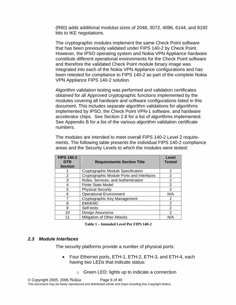
The modules are intended to meet overall FIPS 140-2 Level 2 require-ments. The following table presents the individual FIPS 140-2 compliance areas and the Security Levels to which the modules were tested:
FIPS 140-2 DTR
Section
Requirements Section Title
Level Tested
1 Cryptographic Module Specification 2 2 Cryptographic Module Ports and Interfaces 2 3 Roles, Services, and Authentication 2 4 Finite State Model 2 5 Physical Security 2 6 Operational Environment N/A 7 Cryptographic Key Management 2 8 EMI/EMC 2 9 Self-tests 2 10 Design Assurance 2 11 Mitigation of Other Attacks N/A
Table 1 – Intended Level Per FIPS 140-2
2.3 Module Interfaces The security platforms provide a number of physical ports:
• Four Ethernet ports, ETH-1, ETH-2, ETH-3, and ETH-4, each having two LEDs that indicate status:
o Green LED: lights up to indicate a connection
© Copyright 2005, 2006 Nokia Page 7 of 40 This document may be freely reproduced and distributed whole and intact including this Copyright Notice.
o Yellow LED: blinks when data is transmitted
• Console port
• AUX port (disabled by default; must not be enabled in FIPS mode)
• Interface option slots for the following network interface cards:
o Dual-port 10/100 Ethernet o Single-port V.35 or X.21 I/O cards
• Two type II PCMCIA slots (disabled in FIPS mode)
• Power switch
• Power Plug
• Reset switch
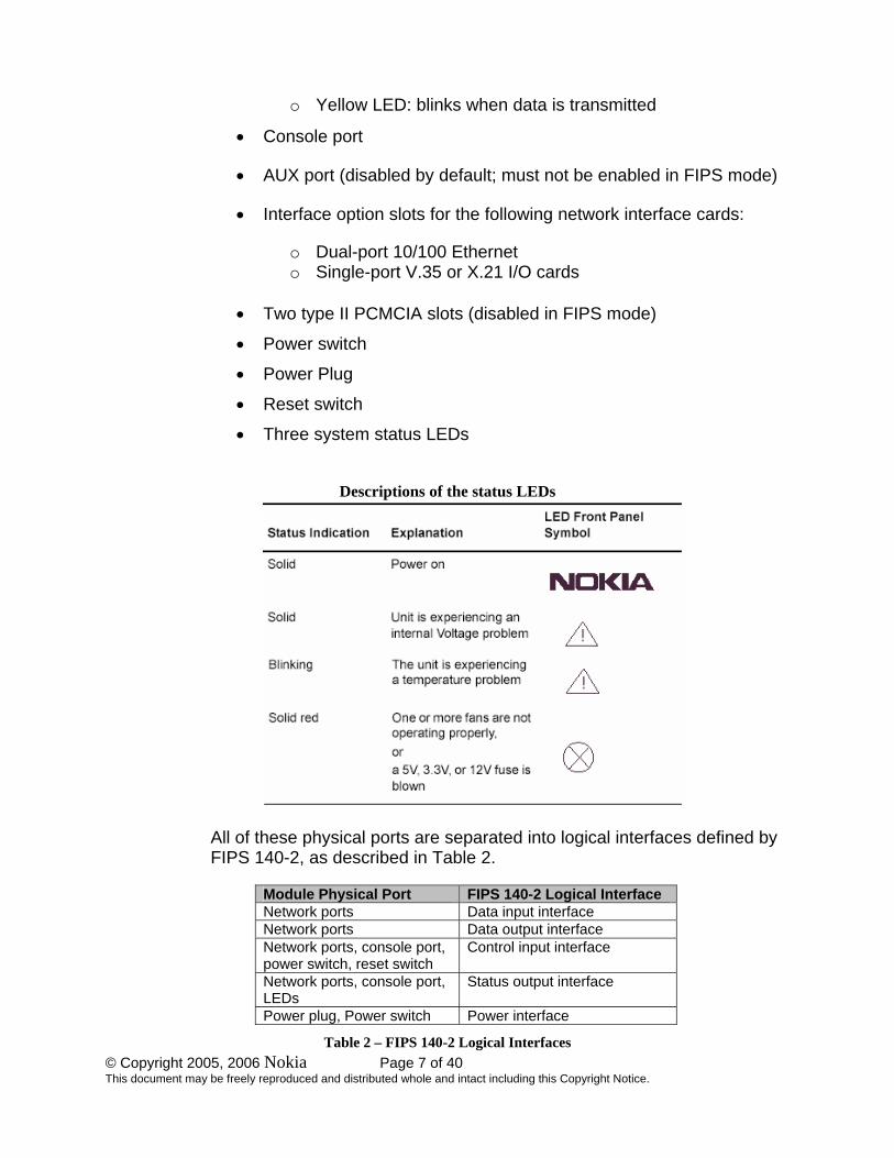
• Three system status LEDs
Descriptions of the status LEDs
All of these physical ports are separated into logical interfaces defined by FIPS 140-2, as described in Table 2.
Module Physical Port FIPS 140-2 Logical Interface Network ports Data input interface Network ports Data output interface Network ports, console port, power switch, reset switch
Control input interface
Network ports, console port, LEDs
Status output interface
Power plug, Power switch Power interface
Table 2 – FIPS 140-2 Logical Interfaces

© Copyright 2005, 2006 Nokia Page 8 of 40 This document may be freely reproduced and distributed whole and intact including this Copyright Notice.
Data input and output, control input, and status output are defined as follows:
• Data input and output are the packets that use the firewall, VPN, and routing functionalities of the modules.
• Control input consists of manual control inputs for power and reset
through the power and reset switch. It also consists of all of the data that is entered into the module while using the management interfaces.
• Status output consists of the status indicators displayed through the
LEDs and the status data that is output from the modules while using the management interfaces.
The modules distinguish between different forms of data, control, and status traffic over the network ports by analyzing the packets header information and contents.
2.4 Roles and Services The modules support role-based authentication. The two main roles in the modules (as required by FIPS 140-2) that operators can assume are: a Crypto Officer role and a User role.
2.4.1 Crypto Officer Role
The Crypto Officer role can configure, manage, and monitor the module. Three management interfaces can be used for this purpose:
• CLI – the Crypto Officer can use the CLI to configure and monitor IPSO systems. This can be done locally by using the console port or remotely by using the SSH secured management session.
• SNMP – the Crypto Officer can use SNMPv3 to view MIB values.
• SmartDashBoard – the Check Point TLS-secured management interface. The Crypto Officer can use this interface after the initial configuration of the Check Point module through the CLI.

© Copyright 2005, 2006 Nokia Page 9 of 40 This document may be freely reproduced and distributed whole and intact including this Copyright Notice.
Figure 1 – Easy to Use Check Point Management Tools
Descriptions of the services available to the Crypto Officer role are provided in Table 3.
Service Description Input Output Critical Security Parameter (CSP) Access
Startup configuration
Provide network connectivity and set a password for the admin account
Commands and configuration data(via local console)
Status of commands and configuration data
Admin password (read/write access)
SSH Provide authenticated and encrypted sessions while using the CLI
SSH key transport (SSHv1) or SSH key agreement (SSHv2) parameters, SSH inputs, and data
SSH outputs and data
RSA (SSHv1 and SSHv2) or DSA (SSHv2) host key pair (read access) ;RSA (SSHv1 and SSHv2) or DSA (SSHv2) authorized key (read access); RSA server key (SSHv1 only, read access); Diffie-Hellman key pair for SSHv2 key exchange (read/write access); session key for SSH (read/write access); X9.31 PRNG keys (read access)

© Copyright 2005, 2006 Nokia Page 10 of 40 This document may be freely reproduced and distributed whole and intact including this Copyright Notice.
Service Description Input Output Critical Security Parameter (CSP) Access
TLS Provide authenticated and encrypted sessions while using the Check Point management interface
TLS handshake parameters, TLS inputs, and data
TLS outputs and data
RSA key pair for TLS key transport (read access); session keys for TLS (read/write access); X9.31 PRNG keys (read access)
Boot manager commands
Control the boot-up process and obtain system information
Commands and configuration data
Status of commands and configur-ation data
Password (read/write access)
SNMPv3 Get commands
View MIB values
Commands Status of commands, configuration data
Password (read access) The password itself is read-write while the v3 service is read access
Interface commands
Configure, manage, and view physical and logical interfaces through the CLI: view all interfaces; delete any logical interface; view tunnels; view status and statistics; configure ARP behavior, physical and logical ATM interfaces, physical and logical Ethernet interfaces, physical and logical FDDI interfaces, physical and logical ISDN interfaces, physical or logical loopback interfaces, and physical and logical serial interfaces
Commands and configuration data
Status of commands and configuration data
Routing commands
Configure, manage, and view the routing protocols through the CLI: configure, manage, and view BGB BGP, OSPF, RIP, IGRP, IGMP, PIM, route aggregation, BOOTP, DVMRP, static routes,, ICMP router discovery, IP broadcast helper, Network Time Protocol, and dial on demand routing; configure a variety of miscellaneous options that affect routing; configure trace routing settings; view summary information about routes on the system; view general information that the IPSO routing daemon records; view information about multicast forwarding cache
Commands and configuration data
Status of commands and configuration data
None
© Copyright 2005, 2006 Nokia Page 11 of 40 This document may be freely reproduced and distributed whole and intact including this Copyright Notice.
Service Description Input Output Critical Security Parameter (CSP) Access
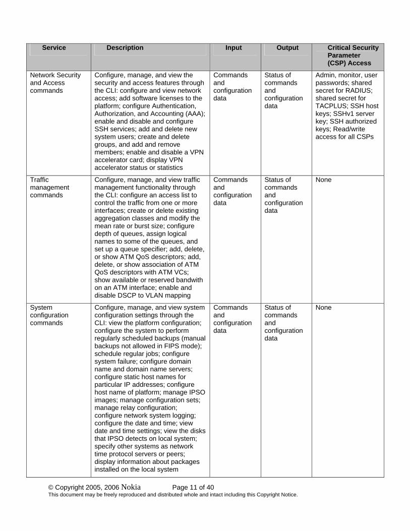
Network Security and Access commands
Configure, manage, and view the security and access features through the CLI: configure and view network access; add software licenses to the platform; configure Authentication, Authorization, and Accounting (AAA); enable and disable and configure SSH services; add and delete new system users; create and delete groups, and add and remove members; enable and disable a VPN accelerator card; display VPN accelerator status or statistics
Commands and configuration data
Status of commands and configuration data
Admin, monitor, user passwords; shared secret for RADIUS; shared secret for TACPLUS; SSH host keys; SSHv1 server key; SSH authorized keys; Read/write access for all CSPs
Traffic management commands
Configure, manage, and view traffic management functionality through the CLI: configure an access list to control the traffic from one or more interfaces; create or delete existing aggregation classes and modify the mean rate or burst size; configure depth of queues, assign logical names to some of the queues, and set up a queue specifier; add, delete, or show ATM QoS descriptors; add, delete, or show association of ATM QoS descriptors with ATM VCs; show available or reserved bandwith on an ATM interface; enable and disable DSCP to VLAN mapping
Commands and configuration data
Status of commands and configuration data
None
System configuration commands
Configure, manage, and view system configuration settings through the CLI: view the platform configuration; configure the system to perform regularly scheduled backups (manual backups not allowed in FIPS mode); schedule regular jobs; configure system failure; configure domain name and domain name servers; configure static host names for particular IP addresses; configure host name of platform; manage IPSO images; manage configuration sets; manage relay configuration; configure network system logging; configure the date and time; view date and time settings; view the disks that IPSO detects on local system; specify other systems as network time protocol servers or peers; display information about packages installed on the local system
Commands and configuration data
Status of commands and configuration data
None
© Copyright 2005, 2006 Nokia Page 12 of 40 This document may be freely reproduced and distributed whole and intact including this Copyright Notice.
Service Description Input Output Critical Security Parameter (CSP) Access
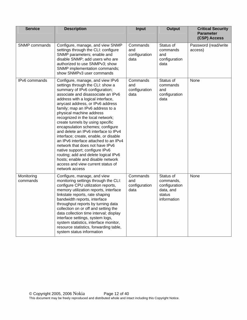
SNMP commands Configure, manage, and view SNMP settings through the CLI: configure SNMP parameters; enable and disable SNMP; add users who are authorized to use SNMPv3; show SNMP implementation commands; show SNMPv3 user commands
Commands and configuration data
Status of commands and configuration data
Password (read/write access)
IPv6 commands Configure, manage, and view IPv6 settings through the CLI: show a summary of IPv6 configuration; associate and disassociate an IPv6 address with a logical interface, anycast address, or IPv6 address family; map an IPv6 address to a physical machine address recognized in the local network; create tunnels by using specific encapsulation schemes; configure and delete an IPv6 interface to IPv4 interface; create, enable, or disable an IPv6 interface attached to an IPv4 network that does not have IPv6 native support; configure IPv6 routing; add and delete logical IPv6 hosts; enable and disable network access and view current status of network access
Commands and configuration data
Status of commands and configuration data
None
Monitoring commands
Configure, manage, and view monitoring settings through the CLI: configure CPU utilization reports, memory utilization reports, interface linkstate reports, rate shaping bandwidth reports, interface throughput reports by turning data collection on or off and setting the data collection time interval; display interface settings, system logs, system statistics, interface monitor, resource statistics, forwarding table, system status information
Commands and configuration data
Status of commands, configuration data, and status information
None
© Copyright 2005, 2006 Nokia Page 13 of 40 This document may be freely reproduced and distributed whole and intact including this Copyright Notice.
Service Description Input Output Critical Security Parameter (CSP) Access
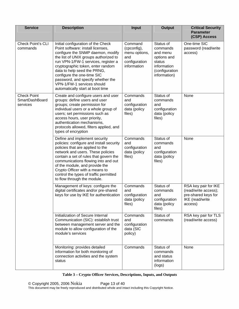
Check Point’s CLI commands
Initial configuration of the Check Point software: install licenses, configure the SNMP daemon, modify the list of UNIX groups authorized to run VPN-1/FW-1 services, register a cryptographic token, enter random data to help seed the PRNG, configure the one-time SIC password, and specify whether the VPN-1/FW-1 services should automatically start at boot time
Command (cpconfig), menu options, and configuration information
Status of commands and menu options and status information (configuration information)
One-time SIC password (read/write access)
Create and configure users and user groups: define users and user groups; create permission for individual users or a whole group of users; set permissions such as access hours, user priority, authentication mechanisms, protocols allowed, filters applied, and types of encryption
Commands and configuration data (policy files)
Status of commands and configuration data (policy files)
None
Define and implement security policies: configure and install security policies that are applied to the network and users. These policies contain a set of rules that govern the communications flowing into and out of the module, and provide the Crypto Officer with a means to control the types of traffic permitted to flow through the module.
Commands and configuration data (policy files)
Status of commands and configuration data (policy files)
None
Management of keys: configure the digital certificates and/or pre-shared keys for use by IKE for authentication
Commands and configuration data (policy files)
Status of commands and configuration data (policy files)
RSA key pair for IKE (read/write access); pre-shared keys for IKE (read/write access)
Initialization of Secure Internal Communication (SIC): establish trust between management server and the module to allow configuration of the module’s services
Commands and configuration data (SIC policy)
Status of commands
RSA key pair for TLS (read/write access)
Check Point SmartDashBoard services
Monitoring: provides detailed information for both monitoring of connection activities and the system status
Commands Status of commands and status information (logs)
None
Table 3 – Crypto Officer Services, Descriptions, Inputs, and Outputs

© Copyright 2005, 2006 Nokia Page 14 of 40 This document may be freely reproduced and distributed whole and intact including this Copyright Notice.
2.4.2 User Role
The User role accesses the module IPSec and IKE services. Service descriptions, inputs, and outputs are listed in Table 4.
Service Description Input Output CSP
IKE Access the module IKE functionality to authenticate to the module and negotiate IKE and IPSec session keys
IKE inputs and data IKE outputs, status, and data
RSA key pair for IKE (read access); Diffie-Hellman key pair for IKE (read/write access); pre-shared keys for IKE (read access)
IPSec Access the module’s IPSec services in order to secure network traffic
IPSec inputs, commands, and data
IPSec outputs, status, and data
Session keys for IPSec (read/write access)
Table 4 – User Services, Descriptions, Inputs and Outputs
2.4.3 Authentication Mechanisms
The modules implement password-based authentication(console and SSH), RSA-based authentication(TLS ,IKE and SSH), DSA-based authentication(SSHv2), and HMAC-based authentication mechanisms (IKE preshared keys).
2.4.3.1 Crypto Officer Authentication
The Crypto Officer must successfully authenticate before a management interface can be accessed. The authentication methods are described below.
• CLI (local) – the Crypto Officer must authenticate by using user ID and password. The password must be at least six characters long. Numeric, alphabetic (upper and lowercase), and keyboard and extended characters can be used.
• CLI (remote) – the Crypto Officer must first successfully authenticate during the SSH session establishment. Before starting the SSH session, the Crypto Officer must login locally at initialization through the console CLI and enter an authorized RSA or DSA public key generated at the client. This public key will be used to authenticate the Crypto Officer during SSH session establishment. Once a session is established, the Crypto Officer can also be asked to authenticate again by using the user ID and

© Copyright 2005, 2006 Nokia Page 15 of 40 This document may be freely reproduced and distributed whole and intact including this Copyright Notice.
password before the management interface can finally be accessed.
• SNMP – the Crypto Officer must authenticate by using the user ID and password. It is the same password used to access the CLI. The only restriction is that the password must be at least eight characters long.
• SmartDashBoard (Check Point Management Station) – during the TLS session establishment between the Check Point management station and the gateway, the Crypto Officer must authenticate by using a digital certificate issued by a trusted Certification Authority (CA).
2.4.3.2 User Authentication
User authentication to the module is performed during IKE using digital certificates or pre-shared keys. The pre-shared keys must be at least six characters long and use at least four different characters.
2.4.3.3 Estimated Strength of the Authentication Mechanisms
The estimated strength of each authentication mechanism implemented by the module is described in Table 5.
Authentication Type
Strength
DSA-based authentication (SSHv2)
DSA signing and verification is used to authenticate the module during SSHv2. This mechanism is as strong as the DSA algorithm using a 1024 bit key pair.
RSA-based authentication (SSHv1, SSHv2 and TLS handshake)
RSA encryption and decryption is used to authenticate the module during SSHv1, SSHv2, and the TLS handshake. This mechanism is as strong as the RSA algorithm using a 1024 bit key pair.
RSA-based authentication (IKE)
RSA signing and verification is used to authenticate to the module during IKE. This mechanism is as strong as the RSA algorithm using a 1024 bit key pair.
Pre-shared key-based authentication (IKE)
SHA-1 HMAC generation and verification is used to authenticate to the module during IKE with pre-shared keys. This mechanism is as strong as the HMAC with SHA-1 algorithm. Additionally, pre-shared keys must be at least six characters long and use at least four different characters. Even if only uppercase letters were used without repetition for a six character pre-shared key, the probability of randomly guessing the correct sequence is one in 165,765,600.

© Copyright 2005, 2006 Nokia Page 16 of 40 This document may be freely reproduced and distributed whole and intact including this Copyright Notice.
Authentication Type
Strength
Password-based authentication
Passwords are required to be at least six characters long. Numeric, alphabetic (upper and lowercase), and keyboard and extended characters can be used, which gives a total of 95 characters to choose from. Considering only the case-insensitive alphabet using a password with repetition, the number of potential passwords is 26^6.
Table 5 – Estimated Strength of Authentication Mechanisms
2.5 Electromechanical Interference/Compatibility (FCC Compliance) Each module hardware configuration was tested and found compliant with requirements for a Class A digital device, pursuant to Part 15 of the FCC rules and thus the FIPS 140-2 Level 2 EMI/EMC requirements.
2.6 Physical Security The Nokia VPN Appliances are multi-chip, standalone cryptographic modules. The modules are entirely contained within their respective hard metal enclosure. The enclosures are resistant to probing and are opaque within the visible spectrum. The front and side vent holes of all enclosures are baffled from the inside using lance wall inserts to prevent direct viewing of the module’s interior components. Rear vent holes are likewise obscured by internal fan or power supply components. Serially numbered tamper-evident seals provide additional protection to those parts of the module chassis that can be opened or disassembled. The seals provide indications of attempts to tamper with the modules. The tamper-evident seals are affixed to the module by the Crypto Officer in numbers and locations that vary depending on the module hardware version. Specific quantities and locations are described in Section 3.1 “Crypto Officer Guidance” of this document.
2.7 Operational Environment The FIPS 140-2 operational environment requirements do not apply to these modules. The Nokia VPN Appliances do not provide a general-purpose operating system nor do they provide a mechanism to load software. The module operator interacts with the module through customized interfaces that provide only specific command options.
2.8 Cryptographic Key Management Cryptographic algorithms are implemented in software by IPSO and Check Point VPN-1 and in hardware by the encryption accelerators.

© Copyright 2005, 2006 Nokia Page 17 of 40 This document may be freely reproduced and distributed whole and intact including this Copyright Notice.
The IPSO operating system provides the capability to use SSHv1 or SSHv2 to secure the remote CLI management sessions. The implemented FIPS-approved algorithms include RSA (SSHv1 and SSHv2) and DSA (SSHv2) for authentication, Triple-DES for data encryption, SHA-1 for data hashing, and HMAC SHA-1 for data packet integrity. Key establishment is performed by using the RSA key transport for SSHv1 and the Diffie-Hellman key agreement for SSHv2.
Check Point provides the capability to use TLSv1 to secure management sessions. The implemented FIPS-approved algorithms include RSA for authentication; DES, Triple-DES, and AES for data encryption; SHA-1 for data hashing; and HMAC SHA-1 for data packet integrity. Key establishment is performed by using RSA key wrapping. The embedded Check Point application supports IPSec/ESP for data encryption and IPSec/AH for data integrity. The Check Point module implements all IKE modes: main, aggressive, and quick, using ISAKMP according to the standard. IKE uses RSA signatures or pre-shared keys for authentication. Key establishment in IKE is performed by using the Diffie-Hellman key agreement technique.
Enhanced VPN performance is achieved by accelerating DES, Triple-DES, and Diffie-Hellman modular exponentiation processing implemented by the Check Point software. Hardware acceleration is accomplished either by hard-wired accelerator chips or by optional version-specific internal accelerator cards that are installed by the factory or reseller prior to delivery to the end-user. The IP380 and IP385 module hardware versions support an optional enhanced accelerator card in addition to a hard-wired, internal accelerator chip. If the optional accelerator card is installed, the hardwired chip is electrically bypassed.
Accelerator chips differ only in performance. The module operating system automatically senses the accelerator chip at power on and performs power on self tests on all the functions provided by the appropriate accelerator chip as well as self-tests for all software-based cryptographic functions.
To summarize, the modules implement the following FIPS-approved algorithms (see Appendix B – Algorithm Validation Certificate Numbers for the algorithm certificate numbers of the validated FIPS-approved algorithms):

© Copyright 2005, 2006 Nokia Page 18 of 40 This document may be freely reproduced and distributed whole and intact including this Copyright Notice.
Data encryption:
• Advanced Encryption Standard (AES) in CBC mode (128 or 256 bit keys) – according to NIST FIPS PUB 197.
• Data Encryption Standard (DES) in CBC mode (56 bit keys) (Transitional Phase Only – Valid until May 19, 2007) – according to NIST FIPS PUB 46-3 (withdrawn).
• Triple DES (3DES) in CBC modes (168 bit keys) – according NIST FIPS PUB 46-3 (withdrawn) and NIST Special Publication 800-67.
Data packet integrity:
• HMAC-SHA-1 (20 byte) – per NIST FIPS PUB 198, RFC 2104 (HMAC: Keyed-Hashing for Message Authentication), and RFC 2404 (using HMAC-SHA-1-96 within ESP and AH).
Data hashing:
• Secure Hash Algorithm (SHA-1) – according to NIST FIPS PUB 180-1
Digital signature:
• Digital Signature Algorithm (DSA) – according to NIST FIPS PUB 186-2 with Change Notice 1
Digital signatures and Key transport:
• RSA – all digital signature implementations are according to PKCS #1
The RSA key wrapping methodologies provide the following encryption strengths during key transport:
SSHv1: provides between 57 bits and 80 bits of encryption strength (default is 70 bits of encryption strength).
SSHv2: provides between 80 and 112 bits of encryption strength.
TLS: provides 80 bits of encryption strength.
Encryption strength is determined in accordance with FIPS 140-2 Implementation Guidance 7.5 and NIST Special Publication 800-57 (Part 1).
© Copyright 2005, 2006 Nokia Page 19 of 40 This document may be freely reproduced and distributed whole and intact including this Copyright Notice.
Key agreement / Key establishment:
• The Diffie-Hellman key agreement key establishment methodology used by the different software implementations present in the module (used for IKE and SSHv2) provides the following encryption strengths:
o IPSO: methodology provides between 57 and 112 bits of encryption strength
o Check Point NGX (R60): methodology provides between 70 and 202 bits of encryption strength.
Encryption strength is determined in accordance with FIPS 140-2 Implementation Guidance 7.5 and NIST Special Publication 800-57 (Part 1).
Pseudo-Random Number Generation:
• ANSI X9.31 PRNG
This module also implements the following PRNGs, which are not used for cryptographic purposes:
• ARC4-based PRNG
• Simple Linear Congruential PRNG
The module implements the following protocols permitted for use in a FIPS-approved mode of operation:
Session security:
• SSHv1 (configured to use FIPS-approved algorithms)
• SSHv2 (configured to use FIPS-approved algorithms)
• TLS v1.0 (configured to use FIPS-approved algorithms) according to RFC 2246
• IPSec (configured to use FIPS-approved algorithms)

© Copyright 2005, 2006 Nokia Page 20 of 40 This document may be freely reproduced and distributed whole and intact including this Copyright Notice.
The module supports the following critical security parameters:
CSPs CSPs type Generation Storage Use Host RSA v1 key pair (via IPSO)
1024-bit RSA private and public key pair
Internal – using X9.31 PRNG
Stored in plaintext on disk
SSH server authentication and key transport to client (SSHv1)
Server RSA v1 key pair (via IPSO)
512-, 640-, 768- (default), 864-, 1024-bit private and public key pair
Internal – using X9.31 PRNG
Stored in plaintext in memory
SSH server authentication and key transport to client (SSHv1)
Host RSA v2 key pair (via IPSO)
512-, 640-, 768- (default), 864-, 1024-bit private and public key pair
Internal – using X9.31 PRNG
Stored in plaintext on disk
SSH server authentication (SSHv2)
Host DSA key pair (via IPSO)
160-bit DSA private key and 1024-bit DSA public key
Internal – using X9.31 PRNG
Stored in plaintext on disk
SSH server authentication to client (SSHv2)
Authorized RSA v1 key (via IPSO)
1024-bit RSA public key
External Stored in plaintext on disk
Client authentication to SSH server (SSHv1)
Authorized RSA v2 key (via IPSO)
1024-bit RSA public key
External Stored in plaintext on disk
Client authentication to SSH server (SSH v2)
Authorized DSA key (via IPSO)
1024-bit DSA public key
External Stored in plaintext on disk
Client authentication to SSH server (SSHv2)
TLS RSA key pair (via Check Point VPN-1)
1024-bit RSA private and public key pair
External Stored in plaintext on disk
TLS server authentication and key transport during TLS handshake
TLS client RSA public key (via Check Point VPN-1)
1024-bit RSA public key
External Stored in plaintext on disk
Client authentication during TLS handshake
IKE RSA key pair (via Check Point VPN-1)
1024-bit RSA private and public key pair
External Stored in plaintext on disk
Server authentication during IKE
IKE client RSA public key (via Check Point VPN-1)
1024-bit RSA public key
External Stored in plaintext on disk
Client authentication during IKE
Pre-shared keys (via Check Point VPN-1)
6-character pre-shared key
External Stored in plaintext on disk
Client and server authentication during IKE

© Copyright 2005, 2006 Nokia Page 21 of 40 This document may be freely reproduced and distributed whole and intact including this Copyright Notice.
CSPs CSPs type Generation Storage Use IKE Diffie-Hellman key pair (via Check Point VPN-1)
Diffie-Hellman private and public key pair Both Check Point Configurations: 768, 1024, 1536 bit keys NGX(R60 only): adds 2048, 3072, 4096, 6144, 8192 bit keys
External Stored in plaintext in memory
Key agreement during IKE
IKE client Diffie-Hellman public key (via Check Point VPN-1)
Diffie-Hellman public key Both Check Point Configurations: 768, 1024, 1536 bit keys NGX(R60 only): adds 2048, 3072, 4096, 6144, 8192 bit keys
External Stored in plaintext in memory
Key agreement during IKE
SSHv2 Diffie-Hellman key pair (via IPSO)
512 to 2048-bit Diffie-Hellman private/public key pair
Internal – using X9.31 PRNG
Stored in plaintext in memory
Key agreement during SSHv2
SSHv2 client Diffie-Hellman public key (via IPSO)
512 to 2048-bit Diffie-Hellman public key
External Stored in plaintext in memory
Key agreement during SSHv2
SSH session keys (via IPSO)
168-bit TDES keys; HMAC SHA-1 keys
Established during the SSH key exchange using RSA key transport (SSHv1) or Diffie-Hellman key agreement (SSHv2)
Stored in plaintext in memory
Secure SSH traffic
TLS session keys (via Check Point VPN-1)
56-bit DES or 168-bit TDES keys; HMAC SHA-1 key
Established during the TLS handshake using RSA key transport
Cached to disk Secure TLS traffic
IPSec session keys (via Check Point VPN-1)
56-bit DES, 128-bit TDES, or 128-, 256-bit AES keys; HMAC SHA-1 key
Established during the Diffie-Hellman key agreement
Stored in plaintext in memory
Secure IPSec traffic
IPSO X9.31 PRNG keys (via IPSO)
128-bit TDES keys Internal – by gathering entropy
Stored in plaintext in memory
IPSO pseudo-random number generator for RSA, DSA, and Diffie-Hellman keys
Check Point X9.31 PRNG keys (via Check Point VPN-1)
128-bit TDES keys Internal – by gathering entropy
Stored in plaintext in memory, but entropy used to generate keys is cached to disk
Check Point pseudo-random number generator for Diffie-Hellman keys

© Copyright 2005, 2006 Nokia Page 22 of 40 This document may be freely reproduced and distributed whole and intact including this Copyright Notice.
CSPs CSPs type Generation Storage Use Passwords (via IPSO)
Six-character password (SNMPv3 requires at least eight characters)
External Stored in plaintext on disk
Authentication for accessing the management interfaces (CLI and SNMPv3); boot manager authentication; RADIUS authentication; TACPLUS authentication
Table 6 – Listing CSPs for the Module
2.8.1 Key Generation
The only keys that can be generated by the modules are RSA public and private keys for SSHv1 and SSHv2, and DSA public and private keys for SSHv2. The FIPS-approved X9.31 PRNG is used to generate these keys.
2.8.2 Key Establishment
The modules implement IKE, SSH, and the TLS handshake for automatic key establishment. Two types of key establishment techniques are employed by the modules: the Diffie-Hellman key agreement and the RSA key wrapping. The Diffie-Hellman key agreement establishes shared secrets during SSHv2 and IKE. The RSA key wrapping/key transport generates shared secrets during SSHv1 and TLS.
2.8.3 Key Entry and Output
All private and secret keys entered into the module are electronically entered. No private or secret keys are output from the module.
2.8.4 Key Storage
All RSA (except the server key) and DSA keys, pre-shared keys, and passwords are stored in plaintext on disk. The TLS session keys and the gathered entropy for the Check Point PRNG keys are cached to disk. All other keys are ephemeral keys and are stored in plaintext in memory.
2.8.5 Key Zeroization
Ephemeral keys can be zeroized by rebooting. All other keys can be zeroized by overwriting or deleting them.

© Copyright 2005, 2006 Nokia Page 23 of 40 This document may be freely reproduced and distributed whole and intact including this Copyright Notice.
2.9 Self-Tests The modules perform a set of self-tests to ensure proper operation in compliance with FIPS 140-2. These self-tests are run during power-up (power-up self-tests) or when certain conditions are met (conditional self-tests). Self tests are performed by both IPSO and the Check Point VPN-1 software components as appropriate. IPSO also implements self tests on the algorithms provided by the hardware encryption accelerator chips. All module versions were functionally tested during FIPS 140-2 conformance testing.
Power-up Self-tests:
• Software integrity tests: the modules use a CRC-32 to check the integrity of its various software components, including verifying the integrity of the Check Point VPN-1 binary code.
• Cryptographic algorithm tests:
o AES-CBC KAT o DES-CBC KAT o Triple-DES-CBC KAT o ANSI X9.31 PRNG KAT o RSA sign/verify and encrypt/decrypt KAT o DSA sign/verify KAT o SHA-1 KAT o HMAC SHA-1 KAT
• Policy file integrity test (bypass mode test): the module performs a SHA-1 check value verification to ensure that the policy files are not modified.
Conditional Self-tests:
• RSA pair-wise consistency test: this test is performed when RSA keys are generated for SSHv1.
• DSA pair-wise consistency test: this test is performed when DSA keys are generated for SSHv2.
• Continuous random number generator tests: these tests are constantly run to detect failure of the random number generators of the module.

© Copyright 2005, 2006 Nokia Page 24 of 40 This document may be freely reproduced and distributed whole and intact including this Copyright Notice.
• Policy file integrity test (bypass mode test): the module performs a SHA-1 check value verification to ensure that the policy files are not modified.
Self Test Error Handling
• If the software integrity tests fail, the module enters the bootloader error state and reboots. If the IPSO kernel modules cryptographic algorithm tests fail, the module enters the kernel panic error state and reboots. If the Check Point kernel module cryptographic algorithm tests fail, the module enters the kernel panic error state and must be rebooted by the Crypto Officer to clear the error.
• If the IPSO conditional self-tests fail, the module enters the error state and reboots. If the Check Point continuous RNG test fails, the module enters the error state and reboots. All other self-test errors cause the module to enter the error state, where all cryptographic services and data output for the problem service is halted until the error state is cleared. Restarting the module or the failed service can clear the error state.
All errors are logged and produce error indicators.
2.10 Design Assurance Nokia and Check Point manage and record their respective source code and associated documentation files. Nokia implements the Concurrent Versions System (CVS) for document and source code management. The Check Point code is maintained by Nokia as a compiled binary file.
The Nokia module hardware data, which includes descriptions, parts data, part types, bills of materials, manufacturers, changes, history, and hardware documentation are managed and recorded using Agile Workplace.
Additionally, Microsoft Visual Source Safe (VSS) version 6.0 and Microsoft SharePoint was used to provide configuration management for the module’s FIPS documentation. These document management utilities provide access control, versioning, and logging.
2.11 Mitigation of Other Attacks The modules do not employ security mechanisms to mitigate specific attacks.

© Copyright 2005, 2006 Nokia Page 25 of 40 This document may be freely reproduced and distributed whole and intact including this Copyright Notice.
3 SECURE OPERATION (APPROVED MODE) The Nokia VPN Appliances meet Level 2 requirements for FIPS 140-2. The following subsections describe how to place and keep the module in FIPS-approved mode of operation. The Crypto Officer must ensure that the module is kept in a FIPS-approved mode of operation. The procedures are described in “Crypto Officer Guidance”.
The User can use the module after the Crypto Officer changes the mode of operation to FIPS-Approved. The secure operation for the User is described in Section 3.2, “User Guidance”.
3.1 Crypto Officer Guidance The secure operation procedures include the initial setup, configuring the Check Point modules in a FIPS compliant manner, and keeping the module in a FIPS-approved mode of operation. These procedures are described in the following sections.
3.1.1 Hardware Setup
The Crypto Officer receives the module in a carton. Within the carton the module is placed inside an ESD bag; two foam end caps are placed on both sides of the chassis, protecting the module during shipping. The Crypto Officer should examine the carton and the ESD bag for evidence of tampering. Tamper-evidence includes tears, scratches, and other irregularities in the packaging.
Since the module does not enforce an access control mechanism before it is initialized, the Crypto Officer must maintain control of the module at all times until the initial setup is complete.
Before turning on the module, the Crypto Officer must ensure that the module meets Level 2 physical security requirements. To satisfy these requirements, the Crypto Officer must install one or more tamper-evident seals (also called “FIPS Tape”) provided in the module’s FIPS kit.
• N431174001 (12 pc) – Tamper-evident seal
After the seal(s) are in place, the Crypto Officer must initialize the module and set the module to FIPS mode.
3.1.1.1 Applying the Tamper-Evident Seal(s)
One tamper seal is required to provide tamper evidence for the module chassis. The tamper-evident seals each contain a unique serial number which aids the Crypto Officer in determining whether the original labels have been replaced. Refer to Figure 2 for a diagram showing the proper placement of the tamper seal on the module case.

© Copyright 2005, 2006 Nokia Page 26 of 40 This document may be freely reproduced and distributed whole and intact including this Copyright Notice.
To apply the serialized seal
1. Apply one tamper seals to the module chassis at the front top of the module as indicated in the figure below.
2. Record the serial number of the applied seal in a security log.
3. Allow 24 hours for the adhesive in the tamper-evident seal to completely cure.
Figure 2 – Tamper Seal Location for a 1U Full-Width Chassis (1 Seal)
3.1.1.2 Module Initialization
Before performing the initial configuration, the Crypto Officer must set the boot manager password to prevent unauthorized access to the module hard disk.
To initialize the appliance
1. Connect the supplied console cable to the local console port on the front panel of the appliance.
2. Connect the other end of the cable to the VT100 console, or a system running a terminal emulation program.
3. Press Return.
4. At the boot manager prompt, enter: BOOTMGR [0] > passwd
5. At the prompt, enter the new password.
© Copyright 2005, 2006 Nokia Page 27 of 40 This document may be freely reproduced and distributed whole and intact including this Copyright Notice.
6. At the prompt, re-enter the new password for verification.
7. IPSO can now be started by entering the boot command.
8. Follow the initial configuration procedures described in the appropriate Appliance Installation Guide.
3.1.2 Installing, Upgrading or Downgrading the Module Software
New modules come preinstalled with the Nokia IPSO operating system and a version of the Check Point VPN-1/Firewall-1 application. The FIPS 140-2 conformant configuration consists of IPSO 3.9 and Check Point VPN-1 version NGX (R60) with Hotfix HFA-03. Depending on the version of the IPSO or Check Point software running on the module when it is received, the Crypto Officer may need to upgrade the supplied IPSO and/or or the Check Point software so that the module is running the validated software configuration. If the desired and installed IPSO/Check Point software versions match the validated configuration, no additional action is required. Otherwise the procedures described in one of the following two scenarios must be followed:
3.1.2.1 SCENARIO 1 – Upgrade Check Point VPN-1 module to NGX (R60)
This scenario applies if module came preinstalled with Check Point VPN-1 version R55p running on IPSO 3.9. The Crypto Officer must delete this version and install NGX (R60): A. Delete Check Point VPN-1 version R55p:
1. Access the device via Voyager, the web-based management interface, Click on the ‘Manage Installed Packages’ link on the ‘Config’ page (i.e., from the home page follow the Config->Manage Installed Packages sequence of links)
2. Turn off Check Point VPN-1 Pro/Express R55p
3. Turn off Check Point SVN Foundation R55 and also any other R55 packages that may have been installed such as Eventia Reporter or User Authority Server
4. Click on ‘Apply’ to make the changes and ‘Save’ to make the changes permanent

© Copyright 2005, 2006 Nokia Page 28 of 40 This document may be freely reproduced and distributed whole and intact including this Copyright Notice.
5. Now click on the ‘Delete Packages’ link. This should show you the list of packages available for deletion
6. Click on the ‘Delete’ radio button for all the packages and ‘Apply’ and ‘Save’
7. You can also optionally delete the R55 tgz file from the /opt/packages directory on the above page
8. Now access the device console, exit and login again if you have a currently active session, and follow the instructions below to install the NGX with (R60) and HFA-03
B. Install Check Point NGX (R60) from the system console:
1. FTP (with user ID and password) the Check Point packages to the system from a remote location and place them under any directory, preferably /opt/packages. (For additional security, choose SFTP or SCP for transferring the file.)
2. From the system console, issue the command /etc/newpkg and select option 4.
3. At the prompt, enter the pathname (for instance /opt/packages).
4. Choose option 1 to install the NGX with R60 package
5. After the install is complete, reboot.
6. Run ‘cpconfig’ after reboot and follow the instructions contained in Section 3.1.3.
7. For instructions on installing NGX (R60) while doing a fresh install of IPSO 3.9 Build 045, please refer to the external document “Installation Guide for FIPS 140-2 Kit and Nokia IPSO 3.9 Build 045”.
8. Follow the instructions below to install HFA (note that the FIPS 140-2 validated Check Point Hot Fix is HFA-03).
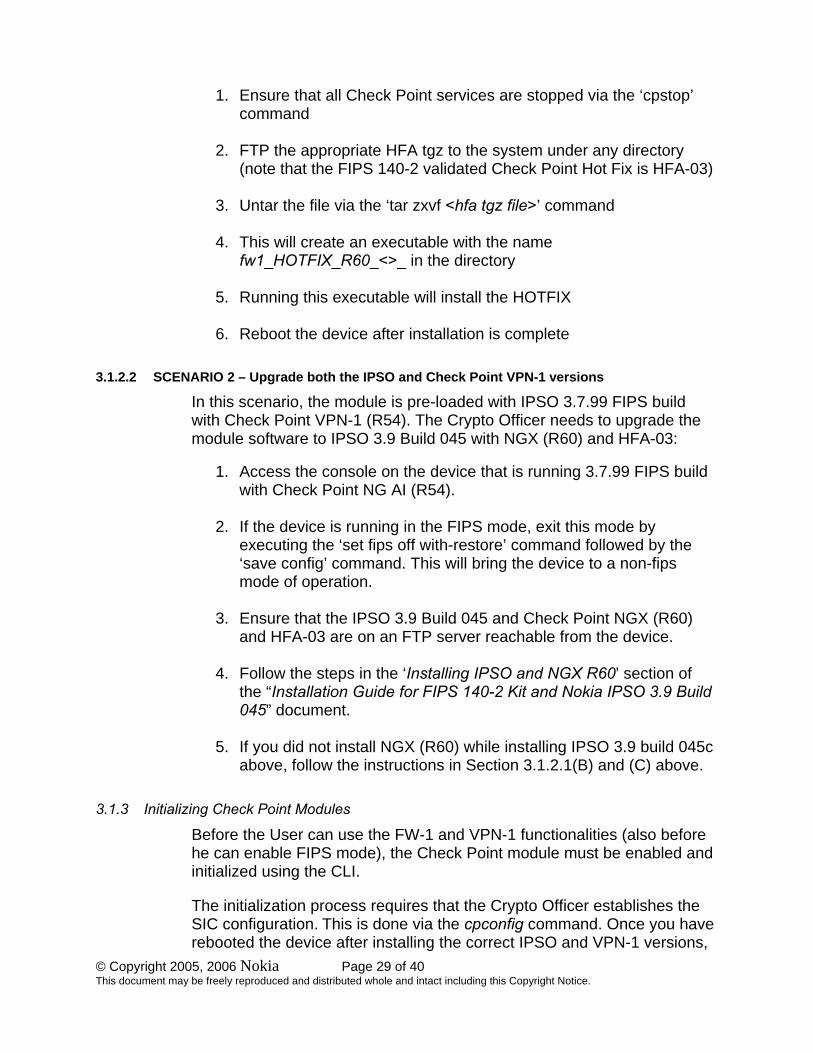
C. Install HFA for Check Point NGX (R60) from the system console:
© Copyright 2005, 2006 Nokia Page 29 of 40 This document may be freely reproduced and distributed whole and intact including this Copyright Notice.
1. Ensure that all Check Point services are stopped via the ‘cpstop’ command
2. FTP the appropriate HFA tgz to the system under any directory (note that the FIPS 140-2 validated Check Point Hot Fix is HFA-03)
3. Untar the file via the ‘tar zxvf <hfa tgz file>’ command
4. This will create an executable with the name fw1_HOTFIX_R60_<>_ in the directory
5. Running this executable will install the HOTFIX
6. Reboot the device after installation is complete
3.1.2.2 SCENARIO 2 – Upgrade both the IPSO and Check Point VPN-1 versions
In this scenario, the module is pre-loaded with IPSO 3.7.99 FIPS build with Check Point VPN-1 (R54). The Crypto Officer needs to upgrade the module software to IPSO 3.9 Build 045 with NGX (R60) and HFA-03:
1. Access the console on the device that is running 3.7.99 FIPS build with Check Point NG AI (R54).
2. If the device is running in the FIPS mode, exit this mode by executing the ‘set fips off with-restore’ command followed by the ‘save config’ command. This will bring the device to a non-fips mode of operation.
3. Ensure that the IPSO 3.9 Build 045 and Check Point NGX (R60) and HFA-03 are on an FTP server reachable from the device.
4. Follow the steps in the ‘Installing IPSO and NGX R60’ section of the “Installation Guide for FIPS 140-2 Kit and Nokia IPSO 3.9 Build 045” document.
5. If you did not install NGX (R60) while installing IPSO 3.9 build 045c above, follow the instructions in Section 3.1.2.1(B) and (C) above.
3.1.3 Initializing Check Point Modules
Before the User can use the FW-1 and VPN-1 functionalities (also before he can enable FIPS mode), the Check Point module must be enabled and initialized using the CLI.
The initialization process requires that the Crypto Officer establishes the SIC configuration. This is done via the cpconfig command. Once you have rebooted the device after installing the correct IPSO and VPN-1 versions,

© Copyright 2005, 2006 Nokia Page 30 of 40 This document may be freely reproduced and distributed whole and intact including this Copyright Notice.
run ‘cpconfig’ and follow the instructions. Be sure to choose the following options during cpconfig: Distributed Installation (option 2) and Enforcement Module (option 1). You will also be prompted to initialize the SIC (Secure Internal Communication). This is used to initialize secure communication with the Check Point SmartCenter Management Station. Also enter a valid Check Point license.
NGX (R60) includes support for Diffie-Hellman Group 14 (2048 bit modulus) key sizes. Groups 15-18 (3072 bits to 8192 bits) can also be optionally configured. To support Groups 15-18, the Local Crypto-Officer must obtain patch SK27054 from Check Point support before beginning the initialization of the module. The patch contains instructions for enabling the additional groups and will be installed during the initialization process.
Using the SmartDashboard application, the Check Point module should be configured for FIPS mode by selecting the screens and options shown in the screen shots included in Section 3.1.6 of this document. Only the screens shown should be configured.
Once this is completed, the module is adequately initialized and can be managed from the management server. FIPS mode can be enabled only after the Check Point initialization is complete
3.1.4 Setting the Module to FIPS Mode
After installing or upgrading to the appropriate Check Point module and initializing the Check Point module, the Crypto Officer must set the mode of operation to FIPS mode.
To set the mode of operation to FIPS mode
1. Use the CLI from the console port to enter the set fips on restart command. This will reboot the device and bring it up in FIPS mode
2. If desired, enter the show fips command to verify that the device is in FIPS mode. For the list of disabled access and feature mechanisms, see Appendix A on page 38.
3.1.5 Initializing the Remote Management of the Module
Before the Crypto Officer can manage the module remotely, SSH must be enabled, the Crypto Officer’s authorized SSH public key must be entered, and only FIPS-approved algorithms can be selected.
To initialize the remote management of the module

© Copyright 2005, 2006 Nokia Page 31 of 40 This document may be freely reproduced and distributed whole and intact including this Copyright Notice.
1. Using the CLI through the console port, enter the set ssh server enable 1 command.
2. To ensure that the Crypto Officer can log in (with a password) using SSH, enter the following command: set ssh server permit-root-login yes
3. Configure the type of authentication that the server will use to authenticate the Crypto Officer by entering the following commands: set ssh server dsa-authentication 1 password-authentication 1 rhosts-authentication 0 rhosts-authentication 0 rsa-authentication 1
4. Allow only FIPS-approved algorithms for encryption and configure the SSH protocol by entering the following commands: set ssh server ciphers 3des-cbc ` keepalives <0 │1> listen-addr IPv4/IPv6 address listen-addr2 IPv4/IPv6 address port <1 │2 │1,2> server-key-bits 1024
5. Generate host keys for either SSHv1, SSHv2, or both by entering the following commands: set ssh hostkey v1 size 1024 set ssh hostkey v2 rsa size 1024 ` v2 dsa size 1024
6. Enter the Crypto Officer’s authorized public key for SSHv1, SSHv2, or both with the following commands: add ssh authkeys v1 user name bits 1024 exponent integer modulus name comment name v2 rsa user name <openssh-format name │ssh-format file name> comment name v2 dsa user name <openssh-format name │ssh-format file name> comment name
7. For optional configuration settings, see the CLI Reference Guide for IPSO 3.7 (for IPSO 3.7.99) or IPSO 3.9 as appropriate.
© Copyright 2005, 2006 Nokia Page 32 of 40 This document may be freely reproduced and distributed whole and intact including this Copyright Notice.
The module can now be managed remotely with SSH-secured management sessions.
When changing the configuration, the preceding settings denoted by bold letters and numbers must not be changed.
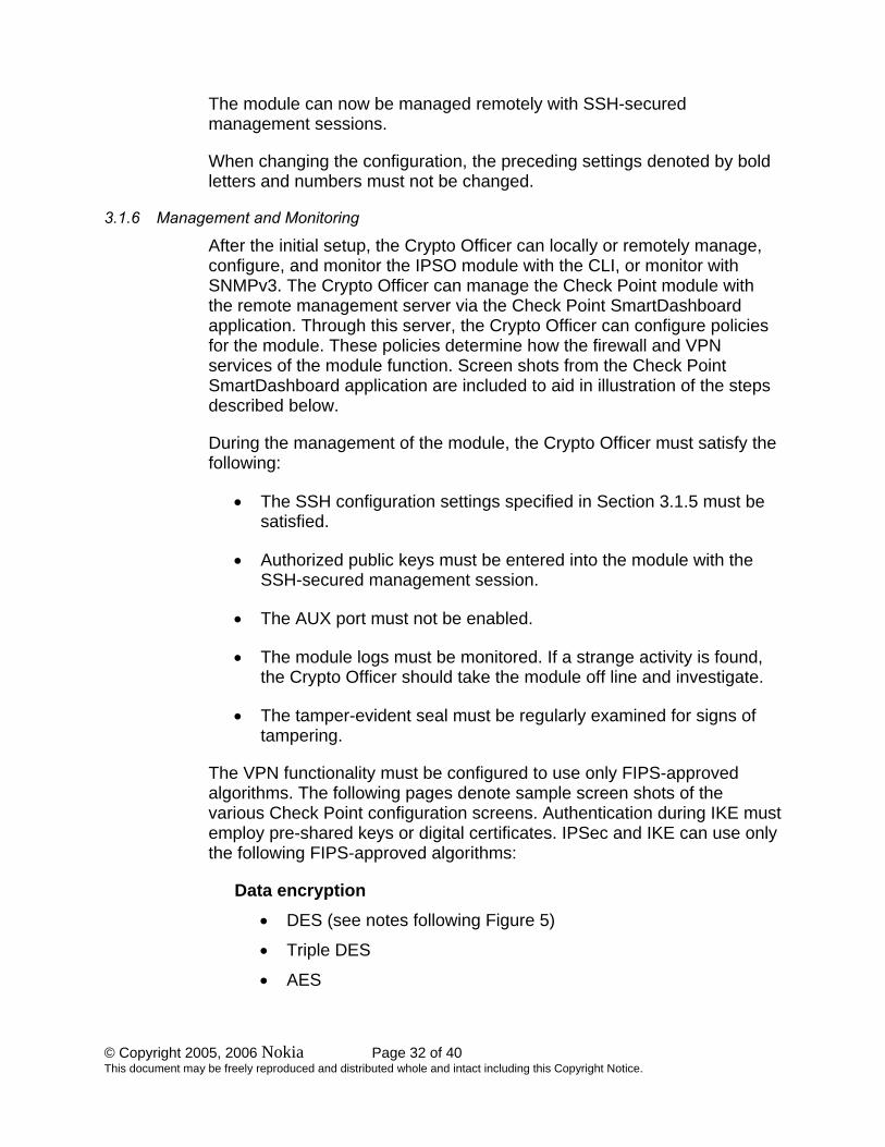
3.1.6 Management and Monitoring
After the initial setup, the Crypto Officer can locally or remotely manage, configure, and monitor the IPSO module with the CLI, or monitor with SNMPv3. The Crypto Officer can manage the Check Point module with the remote management server via the Check Point SmartDashboard application. Through this server, the Crypto Officer can configure policies for the module. These policies determine how the firewall and VPN services of the module function. Screen shots from the Check Point SmartDashboard application are included to aid in illustration of the steps described below.
During the management of the module, the Crypto Officer must satisfy the following:
• The SSH configuration settings specified in Section 3.1.5 must be satisfied.
• Authorized public keys must be entered into the module with the SSH-secured management session.
• The AUX port must not be enabled.
• The module logs must be monitored. If a strange activity is found, the Crypto Officer should take the module off line and investigate.
• The tamper-evident seal must be regularly examined for signs of tampering.
The VPN functionality must be configured to use only FIPS-approved algorithms. The following pages denote sample screen shots of the various Check Point configuration screens. Authentication during IKE must employ pre-shared keys or digital certificates. IPSec and IKE can use only the following FIPS-approved algorithms:
Data encryption • DES (see notes following Figure 5)
• Triple DES
• AES

© Copyright 2005, 2006 Nokia Page 33 of 40 This document may be freely reproduced and distributed whole and intact including this Copyright Notice.
Data packet integrity • HMAC with SHA1
Authentication • Certificates
• Pre-shared keys
Figure 3 – Only FIPS-Approved Algorithms Can Be Used with IKE

© Copyright 2005, 2006 Nokia Page 34 of 40 This document may be freely reproduced and distributed whole and intact including this Copyright Notice.
Figure 4 – Only Pre-shared Keys or Digital Certificates Can Be Used to Authenticate Clients

© Copyright 2005, 2006 Nokia Page 35 of 40 This document may be freely reproduced and distributed whole and intact including this Copyright Notice.
Figure 5 – Only FIPS-Approved Algorithms Can Be Used with IKE
Notes:
1. DES (56 bit) will no longer be allowed in FIPS mode after May 19, 2007.
2. Diffie-Hellman Group 1 (768-bits) provides only 57 bits of encryption strength. After May 19, 2007, only Diffie-Hellman groups 2 or higher, providing 80 or more bits of encryption strength should be used.
3. When Check Point VPN-1 NGX (R60) is used, additional Diffie-Hellman groups
15-18 (2048 bits to 8192 bits) are selectable as options.

© Copyright 2005, 2006 Nokia Page 36 of 40 This document may be freely reproduced and distributed whole and intact including this Copyright Notice.
Figure 6 – Only FIPS-Approved Algorithms Can Be Used with IPSec

© Copyright 2005, 2006 Nokia Page 37 of 40 This document may be freely reproduced and distributed whole and intact including this Copyright Notice.
Figure 7 – Only FIPS-Approved Algorithms Can Be Used with IPSec or IKE
Note: This applies equally for either star or meshed VPN community properties
3.2 User Guidance The User accesses the module VPN functionality as an IPSec client. Although outside the boundary of the module, the User should be careful not to provide authentication information and session keys to other parties.

© Copyright 2005, 2006 Nokia Page 38 of 40 This document may be freely reproduced and distributed whole and intact including this Copyright Notice.
4 APPENDIX A – DISABLED MECHANISMS Warning: When running in a FIPS mode of operation, many of the existing and new features of Nokia IPSO are disabled as required for FIPS compliance.
The following list shows all the access and feature mechanisms that are disabled when the module is in FIPS mode:
• HTTP access
• FTP access
• Telnet access
• TFTP access
• Load Sharing (Nokia IPSO Clustering) and High Availability (VRRP)
• NTP
• Syslog remote logging
• Check Point remote installation daemon
• SSLv3
• Non-FIPS-approved algorithms:
o CAST
o DES (40 bits)
o MD5
o HMAC MD5
o Arcfour
o Twofish
o Blowfish

© Copyright 2005, 2006 Nokia Page 39 of 40 This document may be freely reproduced and distributed whole and intact including this Copyright Notice.
5 APPENDIX B – ALGORITHM VALIDATION CERTIFICATE NUMBERS The module supports several independent implementations of the same FIPS-Approved algorithms. The following table lists the certificate numbers for the validated FIPS-approved algorithms implemented in IPSO, the Check Point VPN-1 software, and the cryptographic accelerator chips. Accelerator cards (when used) accelerate the Check Point software DES, Triple-DES, or AES VPN functions as indicated.
Nokia Software
Check Point Software1
Cryptographic Accelerator Chips
IPSO 3.7.992
IPSO 3.93
NG with AI (R54)2
NGX (R60)3
w/HFA-03
IP350 IP355 IP380 IP385
IP380 IP385
Option4
AES N/A N/A #88 #407 --- --- DES5 N/A N/A #311 #314 #247 #183 3DES6 #234 #234 #333 #440 #235 #132 HMAC affirmed #179 #56 #180 affirmed affirmed SHS #212 #212 #325 #474 #210 #211 DSA #99 #99 N/A N/A N/A N/A RSA7 affirmed #146 #63 #149 N/A N/A RNG8 affirmed #196 #30 #201 N/A N/A
Key Establishment Methodologies: The following key establishment (Key Agreement or Key Wrapping) methodologies are employed by the module. The relative encryption strengths provided by the mechanisms described are calculated in accordance with FIPS 140-2 Implementation Guidance 7.5 and NIST Special Publication 800-57. Note that after May 19, 2007, only methodolo-gies that provide 80 bits or more of encryption strength will remain FIPS Approved. Diffie-Hellman Key Agreement:
• NGX (R60): provides between 70 and 202 bits of encryption strength • IPSO (3.9): provides between 57 and 112 bits of encryption strength
RSA Key Wrapping:
• SSHv1: provides between 57 and 80 bits of encryption strength (the default selection is 70 bits of strength)
1 Check Point algorithms included in FIPS 140-2 Certificate #634 were retested for the specific module platforms and processors identified in this Security Policy. 2 Valid for IP350 and IP380 hardware versions only; See Section 1.1 for previously validated software combinations. 3 Valid for all hardware configurations; See Sections 1.1 and 2.2 for valid software configurations. 4 This accelerator board, when present, electrically bypasses the module’s hardwired chip. 5 Transitional Phase Only – Valid until May 19, 2007; not a FIPS Approved algorithm thereafter. 6 Triple DES using 3 separate keys. 7 RSA PKCS#1 Implementation. 8 ANSI X9.31 PRNG

© Copyright 2005, 2006 Nokia Page 40 of 40 This document may be freely reproduced and distributed whole and intact including this Copyright Notice.
• SSHv2: provides between 80 and 112 bits of encryption strength • TLS: provides 80 bits of encryption strength
6 ACRONYM DEFINITIONS
AH Authentication Header AI Application Intelligence ANSI American National Standards Institute BGP Border Gateway Protocol CBC Cipher Block Chaining CLI Command-Line Interface CMVP Cryptographic Module Validation Program CRC Cyclical Redundancy Check CSP Critical Security Parameter DSA Digital Signature Standard DVMRP Distance Vector Multicast Routing Protocol EDC Error Detection Code EMC Electromagnetic Compatibility EMI Electromagnetic Interference ESP Encapsulating Security Payload FCC Federal Communication Commission FIPS Federal Information Processing Standard FP Feature Pack IGRP Inter-Gateway Routing Protocol IKE Internet Key Exchange IPSec IP Security KAT Known Answer Test LED Light Emitting Diode MAC Message Authentication Code NIST National Institute of Standards and Technology OSPF Open Shortest Path First PRNG Pseudo Random Number Generator RAM Random Access Memory RIP Routing Information Protocol RSA Rivest Shamir and Adleman SA Security Association SHA Secure Hash Algorithm SIC Secure Internal Communications SNMP Simple Network Management Protocol SSH Secure Shell SSL Secure Socket Layer TLS Transport Layer Security VPN Virtual Private Network