Noise measurement system meets new ISO standards in … · Noise measurement system meets new ISO...
8
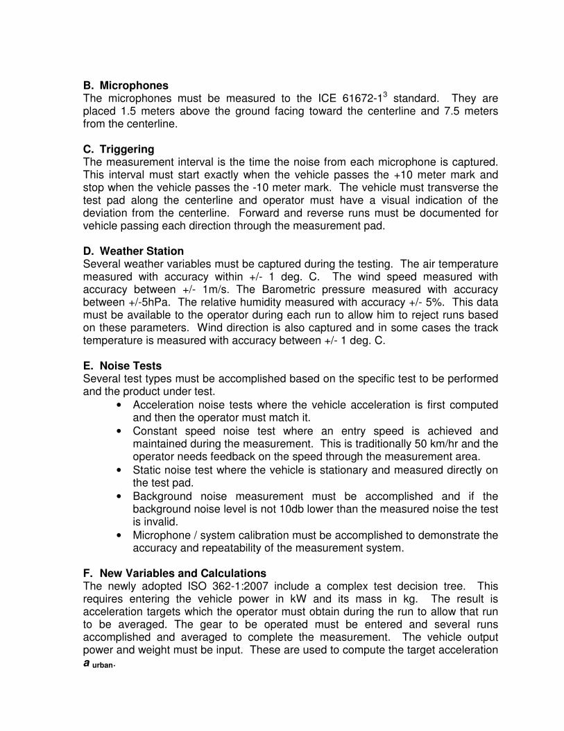
Noise measurement system meets new ISO standards in Pass By Noise with unique global positioning and triggering capabilities Timothy J. Copeland m+p international, inc. Verona, NJ A. INTRODUCTION This paper details the new updates to the ISO 362 Pass By Noise standard and describes a unique solution approach. Pass By Noise ISO 362-1:2007 1 , Acoustics - Measurement of noise emitted by accelerating road vehicles has recently superseded the ISO 362-1998. This standard specifies an engineering method for measuring the noise emitted by road vehicles of specific categories. The specifications are intended to reproduce the level of noise generated by the principal noise sources during normal driving in urban traffic. Adopters must also retain the ability to calculate the previous ISO-362-1998 regulation. The newly adopted standards add complexity to the operation and calculation of results. The new requirements are detailed and how a unique global positioning system (GPS) based system has addressed them. B. REQUIREMENTS The requirements for the successful operation of pass by noise are lengthy. These include the test track, microphones, triggering, weather station, noise test types, variables and calculations and reporting and results. These requirements must be met along with performance and weather conditions to achieve a valid test. Data and the operation of the inside-vehicle and outside-vehicle systems must be synchronized by the operator. A. Test Track The test method defines the environment and physical geometry of the testing to insure accuracy. The physical layout of the measurement pad is defined in ISO 10844 2 . The method requires testing in a wide open space without interference from structures or other features such as berms or trees for a distance of 50 meters. The asphalt measurement test pad has a 15 meter width with a length of 20 meters.
Transcript of Noise measurement system meets new ISO standards in … · Noise measurement system meets new ISO...
Noise measurement system meets new ISO standards in Pass By Noise with unique global positioning and triggering capabilities
Timothy J. Copeland
m+p international, inc. Verona, NJ
A. INTRODUCTION This paper details the new updates to the ISO 362 Pass By Noise standard and describes a unique solution approach. Pass By Noise ISO 362-1:20071, Acoustics - Measurement of noise emitted by accelerating road vehicles has recently superseded the ISO 362-1998. This standard specifies an engineering method for measuring the noise emitted by road vehicles of specific categories. The specifications are intended to reproduce the level of noise generated by the principal noise sources during normal driving in urban traffic. Adopters must also retain the ability to calculate the previous ISO-362-1998 regulation. The newly adopted standards add complexity to the operation and calculation of results. The new requirements are detailed and how a unique global positioning system (GPS) based system has addressed them. B. REQUIREMENTS The requirements for the successful operation of pass by noise are lengthy. These include the test track, microphones, triggering, weather station, noise test types, variables and calculations and reporting and results. These requirements must be met along with performance and weather conditions to achieve a valid test. Data and the operation of the inside-vehicle and outside-vehicle systems must be synchronized by the operator.
A. Test Track The test method defines the environment and physical geometry of the testing to insure accuracy. The physical layout of the measurement pad is defined in ISO 108442. The method requires testing in a wide open space without interference from structures or other features such as berms or trees for a distance of 50 meters. The asphalt measurement test pad has a 15 meter width with a length of 20 meters.
B. Microphones The microphones must be measured to the ICE 61672-13 standard. They are placed 1.5 meters above the ground facing toward the centerline and 7.5 meters from the centerline. C. Triggering The measurement interval is the time the noise from each microphone is captured. This interval must start exactly when the vehicle passes the +10 meter mark and stop when the vehicle passes the -10 meter mark. The vehicle must transverse the test pad along the centerline and operator must have a visual indication of the deviation from the centerline. Forward and reverse runs must be documented for vehicle passing each direction through the measurement pad. D. Weather Station Several weather variables must be captured during the testing. The air temperature measured with accuracy within +/- 1 deg. C. The wind speed measured with accuracy between +/- 1m/s. The Barometric pressure measured with accuracy between +/-5hPa. The relative humidity measured with accuracy +/- 5%. This data must be available to the operator during each run to allow him to reject runs based on these parameters. Wind direction is also captured and in some cases the track temperature is measured with accuracy between +/- 1 deg. C.
E. Noise Tests Several test types must be accomplished based on the specific test to be performed and the product under test.
• Acceleration noise tests where the vehicle acceleration is first computed and then the operator must match it.
• Constant speed noise test where an entry speed is achieved and maintained during the measurement. This is traditionally 50 km/hr and the operator needs feedback on the speed through the measurement area.
• Static noise test where the vehicle is stationary and measured directly on the test pad.
• Background noise measurement must be accomplished and if the background noise level is not 10db lower than the measured noise the test is invalid.
• Microphone / system calibration must be accomplished to demonstrate the accuracy and repeatability of the measurement system.
F. New Variables and Calculations The newly adopted ISO 362-1:2007 include a complex test decision tree. This requires entering the vehicle power in kW and its mass in kg. The result is acceleration targets which the operator must obtain during the run to allow that run to be averaged. The gear to be operated must be entered and several runs accomplished and averaged to complete the measurement. The vehicle output power and weight must be input. These are used to compute the target acceleration a urban.
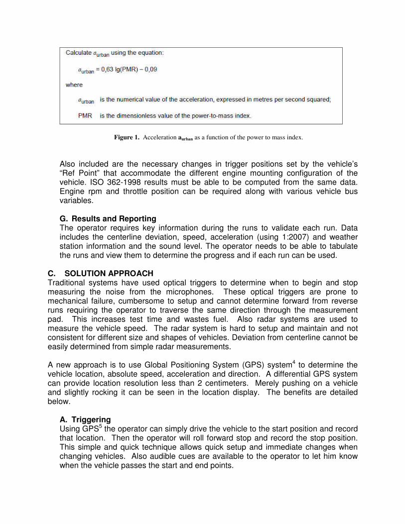
Figure 1. Acceleration aurban as a function of the power to mass index.
Also included are the necessary changes in trigger positions set by the vehicle’s “Ref Point” that accommodate the different engine mounting configuration of the vehicle. ISO 362-1998 results must be able to be computed from the same data. Engine rpm and throttle position can be required along with various vehicle bus variables.
G. Results and Reporting The operator requires key information during the runs to validate each run. Data includes the centerline deviation, speed, acceleration (using 1:2007) and weather station information and the sound level. The operator needs to be able to tabulate the runs and view them to determine the progress and if each run can be used.
C. SOLUTION APPROACH Traditional systems have used optical triggers to determine when to begin and stop measuring the noise from the microphones. These optical triggers are prone to mechanical failure, cumbersome to setup and cannot determine forward from reverse runs requiring the operator to traverse the same direction through the measurement pad. This increases test time and wastes fuel. Also radar systems are used to measure the vehicle speed. The radar system is hard to setup and maintain and not consistent for different size and shapes of vehicles. Deviation from centerline cannot be easily determined from simple radar measurements. A new approach is to use Global Positioning System (GPS) system4 to determine the vehicle location, absolute speed, acceleration and direction. A differential GPS system can provide location resolution less than 2 centimeters. Merely pushing on a vehicle and slightly rocking it can be seen in the location display. The benefits are detailed below.
A. Triggering Using GPS5 the operator can simply drive the vehicle to the start position and record that location. Then the operator will roll forward stop and record the stop position. This simple and quick technique allows quick setup and immediate changes when changing vehicles. Also audible cues are available to the operator to let him know when the vehicle passes the start and end points.
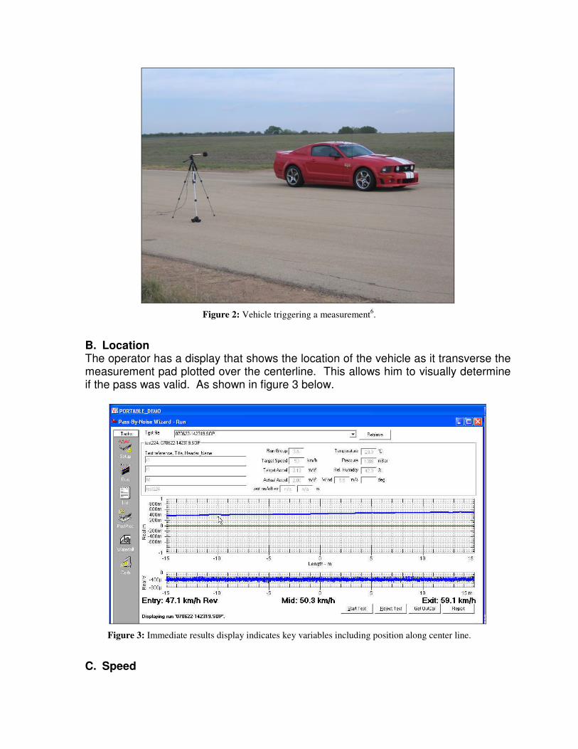
Figure 2: Vehicle triggering a measurement6.
B. Location The operator has a display that shows the location of the vehicle as it transverse the measurement pad plotted over the centerline. This allows him to visually determine if the pass was valid. As shown in figure 3 below.
Figure 3: Immediate results display indicates key variables including position along center line.
C. Speed
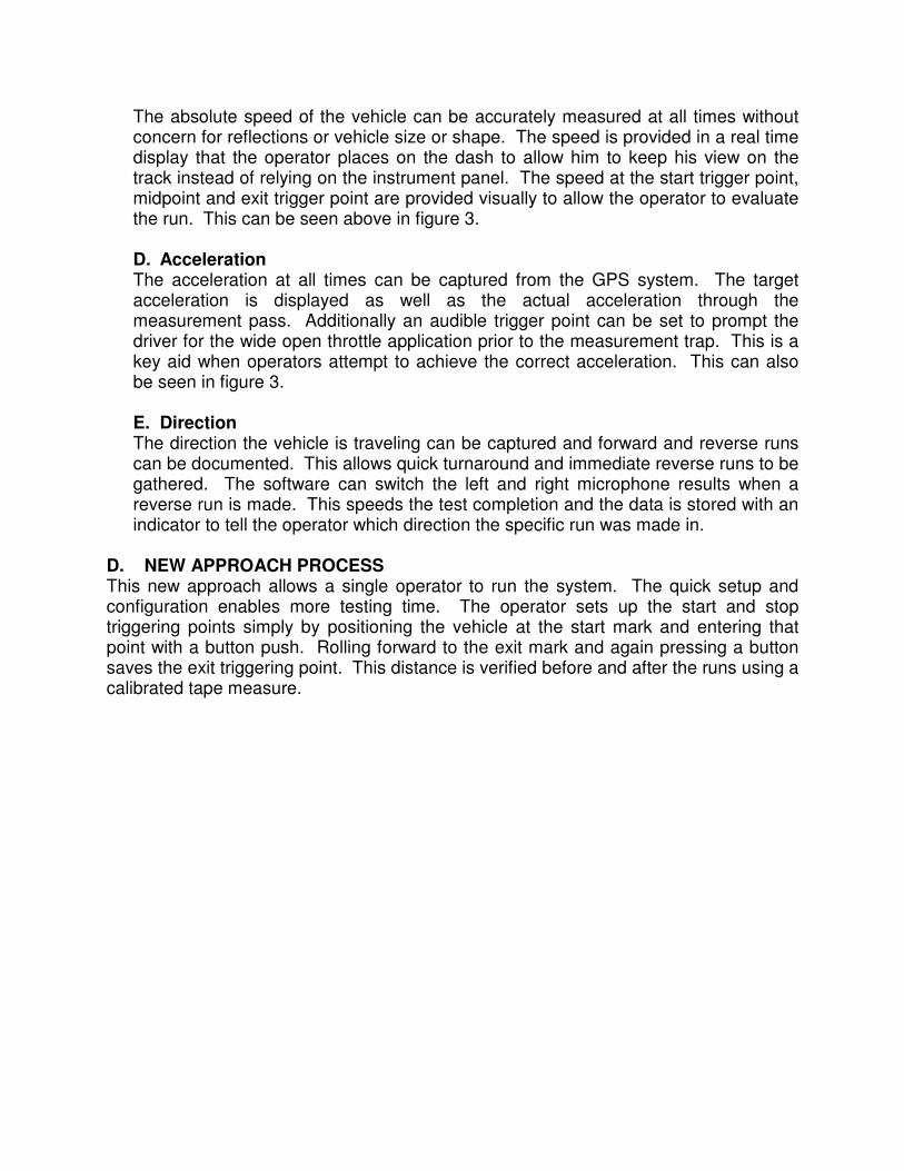
The absolute speed of the vehicle can be accurately measured at all times without concern for reflections or vehicle size or shape. The speed is provided in a real time display that the operator places on the dash to allow him to keep his view on the track instead of relying on the instrument panel. The speed at the start trigger point, midpoint and exit trigger point are provided visually to allow the operator to evaluate the run. This can be seen above in figure 3.
D. Acceleration The acceleration at all times can be captured from the GPS system. The target acceleration is displayed as well as the actual acceleration through the measurement pass. Additionally an audible trigger point can be set to prompt the driver for the wide open throttle application prior to the measurement trap. This is a key aid when operators attempt to achieve the correct acceleration. This can also be seen in figure 3. E. Direction The direction the vehicle is traveling can be captured and forward and reverse runs can be documented. This allows quick turnaround and immediate reverse runs to be gathered. The software can switch the left and right microphone results when a reverse run is made. This speeds the test completion and the data is stored with an indicator to tell the operator which direction the specific run was made in.
D. NEW APPROACH PROCESS This new approach allows a single operator to run the system. The quick setup and configuration enables more testing time. The operator sets up the start and stop triggering points simply by positioning the vehicle at the start mark and entering that point with a button push. Rolling forward to the exit mark and again pressing a button saves the exit triggering point. This distance is verified before and after the runs using a calibrated tape measure.
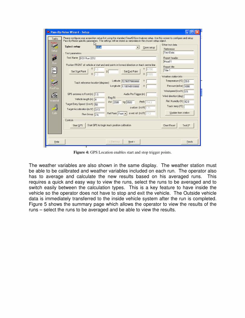
Figure 4: GPS Location enables start and stop trigger points.
The weather variables are also shown in the same display. The weather station must be able to be calibrated and weather variables included on each run. The operator also has to average and calculate the new results based on his averaged runs. This requires a quick and easy way to view the runs, select the runs to be averaged and to switch easily between the calculation types. This is a key feature to have inside the vehicle so the operator does not have to stop and exit the vehicle. The Outside vehicle data is immediately transferred to the inside vehicle system after the run is completed. Figure 5 shows the summary page which allows the operator to view the results of the runs – select the runs to be averaged and be able to view the results.
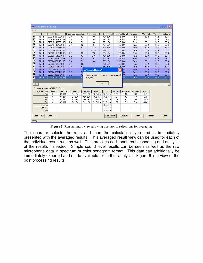
Figure 5: Run summary view allowing operator to select runs for averaging.
The operator selects the runs and then the calculation type and is immediately presented with the averaged results. This averaged result view can be used for each of the individual result runs as well. This provides additional troubleshooting and analysis of the results if needed. Simple sound level results can be seen as well as the raw microphone data in spectrum or color sonogram format. This data can additionally be immediately exported and made available for further analysis. Figure 6 is a view of the post processing results.
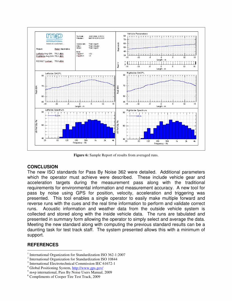
Figure 6: Sample Report of results from averaged runs.
CONCLUSION The new ISO standards for Pass By Noise 362 were detailed. Additional parameters which the operator must achieve were described. These include vehicle gear and acceleration targets during the measurement pass along with the traditional requirements for environmental information and measurement accuracy. A new tool for pass by noise using GPS for position, velocity, acceleration and triggering was presented. This tool enables a single operator to easily make multiple forward and reverse runs with the cues and the real time information to perform and validate correct runs. Acoustic information and weather data from the outside vehicle system is collected and stored along with the inside vehicle data. The runs are tabulated and presented in summary form allowing the operator to simply select and average the data. Meeting the new standard along with computing the previous standard results can be a daunting task for test track staff. The system presented allows this with a minimum of support.
REFERENCES 1 International Organization for Standardization ISO 362-1:2007
2 International Organization for Standardization ISO 10844
3 International Electrotechnical Commission IEC 61672-1
4 Global Positioning System, http://www.gps.gov/
5 m+p international, Pass By Noise Users Manual, 2009
6 Compliments of Cooper Tire Test Track, 2009