NOAA-N Prime - NASA Prime Booklet... · NOAA-N Prime/2 NOAA-N Prime/3 POES PROGRAM The NOAA...
26
NOAA-N Prime NOAA-N Prime U.S Department of Commerce National Oceanic and Atmospheric Administration National Environmental Satellite Data, and Information Service Suitland, Maryland National Aeronautics and Space Administration Goddard Space Flight Center Greenbelt, Maryland NP-2008-10-056-GSFC
Transcript of NOAA-N Prime - NASA Prime Booklet... · NOAA-N Prime/2 NOAA-N Prime/3 POES PROGRAM The NOAA...
NOAA-N PrimeNOAA-N Prime
U.S Department of CommerceNational Oceanic and
Atmospheric AdministrationNational Environmental Satellite
Data, and Information ServiceSuitland, Maryland
National Aeronautics andSpace Administration
Goddard Space Flight CenterGreenbelt, Maryland
NP-2008-10-056-GSFC
NOAA-N Prime/1
Table of Contents
POES Program ����������������������������������������������������������������������������������������������������������������������������������3 The NOAA Polar-orbiting Satellites �������������������������������������������������������������������������������������3 Initial Joint Polar-orbiting Operational Satellite System ������������������������������������������������������4 NOAA-N Prime ��������������������������������������������������������������������������������������������������������������������7NOAA-N Prime Instruments ������������������������������������������������������������������������������������������������������������7 Advanced Very High Resolution Radiometer (AVHRR/3) ��������������������������������������������������8 High Resolution Infrared Radiation Sounder (HIRS/4) �������������������������������������������������������8 Advanced Microwave Sounding Unit-A (AMSU-A) ����������������������������������������������������������9 Microwave Humidity Sounder (MHS) ���������������������������������������������������������������������������������9 Solar Backscatter Ultraviolet Spectral Radiometer (SBUV/2) �������������������������������������������10 Space Environment Monitor (SEM-2) ��������������������������������������������������������������������������������11 Advanced Data Collection System (ADCS) �����������������������������������������������������������������������11 Search And Rescue (SAR) Instruments ������������������������������������������������������������������������������13 Digital Data Recorder (DDR) ���������������������������������������������������������������������������������������������15NOAA-N Prime Significant Changes ���������������������������������������������������������������������������������������������15Delta II Launch Vehicle ������������������������������������������������������������������������������������������������������������������16NOAA-N Prime Orbit ���������������������������������������������������������������������������������������������������������������������17Polar-orbiting Operational Environmental Satellite Products ��������������������������������������������������������19Spacecraft Data Communications ���������������������������������������������������������������������������������������������������28 Command and Data Acquisition (CDA) Station Downlinks ����������������������������������������������28 Direct Broadcast Downlinks �����������������������������������������������������������������������������������������������28 Search and Rescue Downlinks ��������������������������������������������������������������������������������������������30National Environmental Satellite, Data, And Information Service (NESDIS) ������������������������������31 Satellite Operations Control Center (SOCC) ����������������������������������������������������������������������31 Environmental Satellite Processing Center (ESPC) �����������������������������������������������������������32Other Support Systems �������������������������������������������������������������������������������������������������������������������32 Search and Rescue Ground System ������������������������������������������������������������������������������������32 Goddard Space Flight Center Facility Support �������������������������������������������������������������������32 The North American Aerospace Defense Command (NORAD) ����������������������������������������33 Launch, early orbit, and contingency downlink �����������������������������������������������������������������33Synopsis of Prior Spacecraft �����������������������������������������������������������������������������������������������������������34Mission Summary and Acknowledgement �������������������������������������������������������������������������������������39Appendix A: Channel Characteristics ���������������������������������������������������������������������������������������������40Appendix B: Communications and Data Handling ������������������������������������������������������������������������43Appendix C: NOAA-N Prime Activation and Evaluation Timeline ����������������������������������������������44Glossary ������������������������������������������������������������������������������������������������������������������������������������������46
NOAA-N Prime/2 NOAA-N Prime/3
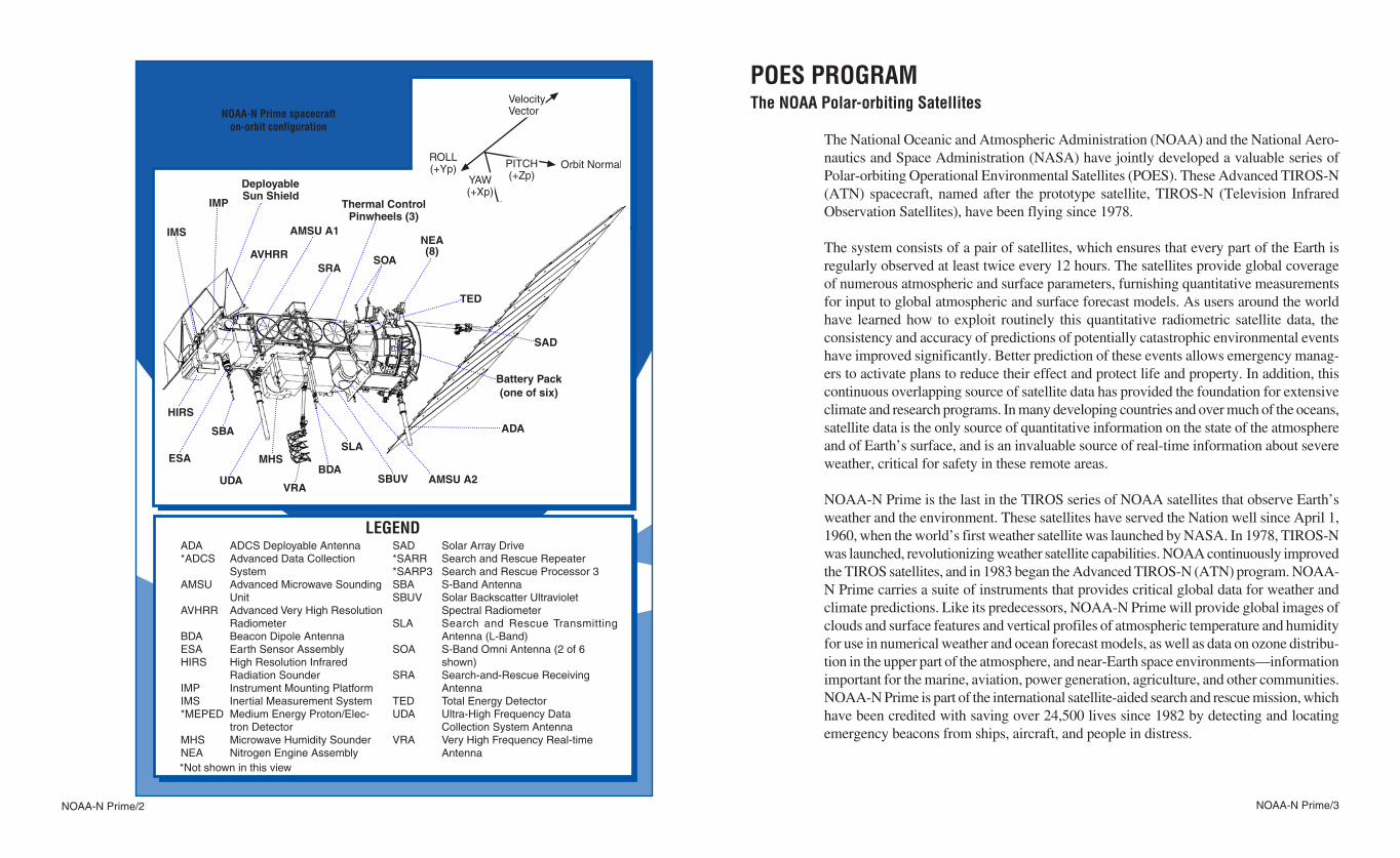
POES PROGRAMThe NOAA Polar-orbiting Satellites
The National Oceanic and Atmospheric Administration (NOAA) and the National Aero-nautics and Space Administration (NASA) have jointly developed a valuable series of Polar-orbiting Operational Environmental Satellites (POES)� These Advanced TIROS-N (ATN) spacecraft, named after the prototype satellite, TIROS-N (Television Infrared Observation Satellites), have been flying since 1978�
The system consists of a pair of satellites, which ensures that every part of the Earth is regularly observed at least twice every 12 hours� The satellites provide global coverage of numerous atmospheric and surface parameters, furnishing quantitative measurements for input to global atmospheric and surface forecast models� As users around the world have learned how to exploit routinely this quantitative radiometric satellite data, the consistency and accuracy of predictions of potentially catastrophic environmental events have improved significantly� Better prediction of these events allows emergency manag-ers to activate plans to reduce their effect and protect life and property� In addition, this continuous overlapping source of satellite data has provided the foundation for extensive climate and research programs� In many developing countries and over much of the oceans, satellite data is the only source of quantitative information on the state of the atmosphere and of Earth’s surface, and is an invaluable source of real-time information about severe weather, critical for safety in these remote areas�
NOAA-N Prime is the last in the TIROS series of NOAA satellites that observe Earth’s weather and the environment� These satellites have served the Nation well since April 1, 1960, when the world’s first weather satellite was launched by NASA� In 1978, TIROS-N was launched, revolutionizing weather satellite capabilities� NOAA continuously improved the TIROS satellites, and in 1983 began the Advanced TIROS-N (ATN) program� NOAA-N Prime carries a suite of instruments that provides critical global data for weather and climate predictions� Like its predecessors, NOAA-N Prime will provide global images of clouds and surface features and vertical profiles of atmospheric temperature and humidity for use in numerical weather and ocean forecast models, as well as data on ozone distribu-tion in the upper part of the atmosphere, and near-Earth space environments—information important for the marine, aviation, power generation, agriculture, and other communities� NOAA-N Prime is part of the international satellite-aided search and rescue mission, which have been credited with saving over 24,500 lives since 1982 by detecting and locating emergency beacons from ships, aircraft, and people in distress�
NOAA-N Prime spacecraft on-orbit configuration
SAD Solar Array Drive*SARR Search and Rescue Repeater*SARP3 Search and Rescue Processor 3SBA S-Band AntennaSBUV Solar Backscatter Ultraviolet Spectral RadiometerSLA Search and Rescue Transmitting
Antenna (L-Band)SOA S-Band Omni Antenna (2 of 6
shown)SRA Search-and-Rescue Receiving
AntennaTED Total Energy DetectorUDA Ultra-High Frequency Data Collection System AntennaVRA Very High Frequency Real-time Antenna
ADA ADCS Deployable Antenna*ADCS Advanced Data Collection SystemAMSU Advanced Microwave Sounding
UnitAVHRR Advanced Very High Resolution
RadiometerBDA Beacon Dipole AntennaESA Earth Sensor AssemblyHIRS High Resolution Infrared
Radiation SounderIMP Instrument Mounting PlatformIMS Inertial Measurement System*MEPED Medium Energy Proton/Elec-
tron DetectorMHS Microwave Humidity SounderNEA Nitrogen Engine Assembly
LEGEND
*Not shown in this view
NOAA-N Prime/4 NOAA-N Prime/5
Initial Joint Polar-orbiting Operational Satellite System (IJPS)
The launch of NOAA-N Prime continues an era of international cooperation and a new model for future polar-orbiting environmental satellite systems� In 1998, the European Organisation for the Exploitation of Meteorological Satellites (EUMETSAT) and NOAA signed an agreement to collaborate in the Initial Joint Polar-orbiting Operational Satellite System (IJPS), comprising two polar-orbiting satellite systems and their respective ground segments� Through a further agreement—the Joint Transition activities agreement signed in 2003—EUMETSAT and NOAA agreed to provide an operational polar-orbiting service until at least 2019� The primary mission of IJPS is to collect and exchange the polar satellite environmental data between NOAA and EUMETSAT and to disseminate this data to users worldwide in support of continued and improved operational meteorological and environmental forecast-ing and global climate monitoring� These services have been furnished largely by NOAA since 1960 with the assistance of a few international partners who have provided additional instruments to complete the satellites’ sensor suites� This agreement commits NOAA to provide the NOAA-18 and NOAA-N Prime satellites for launch into an afternoon orbit (the satellites cross the Equator northbound in the afternoon), carrying the EUMETSAT provided Microwave Humidity Sounder (MHS) along with a NOAA provided suite of instruments� EUMETSAT, in turn, agrees to provide and launch three European-built meteorological satellites, MetOp-1, MetOp-2, and MetOp-3, into a morning orbit carrying the NOAA payload as well as several new sensors developed by EUMETSAT� Addition-ally, both NOAA and EUMETSAT upgraded their ground systems to receive, process, and distribute data from each other’s satellites and they back up each other in the event of anomalies� The EUMETSAT Polar System (EPS) is operated by EUMETSAT and has been developed, procured, and implemented in partnership with the European Space Agency (ESA), the Centre National d’Études Spatiales (CNES) and NOAA�
The MetOp series of three satellites was jointly established by ESA and EUMETSAT, forming the space segment of the EPS� The program represents the European contribu-tion to a new cooperative venture with NOAA, which for more than 40 years has been delivering meteorological data from polar orbit, free of charge, to users worldwide� MetOp carries a new generation of operational meteorological European instruments developed by EUMETSAT, ESA, and CNES, which offer enhanced remote sensing capabilities� The European instruments are the Infrared Atmospheric Sounding Interferometer (IASI), the Advanced Scatterometer (ASCAT), and the instrument for the Global Ozone Monitoring Experiment (GOME-2)� IASI provides atmospheric temperature information with high vertical resolutions, and a scatterometer provides ocean surface wind speed and direc-tion� The GOME-2 instrument provides a second source of ozone observations, which
will complement the data from the SBUV/2 ozone instrument on NOAA-N Prime� The European instruments will complement a set of core instruments, which are flying on the NOAA satellites, and provided by NOAA to EUMETSAT for the MetOp satellites� The core instruments consist of the AVHRR instrument and the Advanced TIROS Operational Vertical Sounder (ATOVS) suite consisting of the HIRS/4 and AMSU-A instruments� The EUMETSAT-provided MHS instrument completes the ATOVS suite� MetOp is also equipped with a search-and-rescue receiver and transmitter for use by emergency services, and a data collection and location system (ARGOS) for receiving and re-transmitting signals from transmitters on ground-based systems� The SEM instrument, provided by NOAA, completes the MetOp payload�
The increased incidence of severe weather events is being linked to changes in the global climate� Achieving greater understanding of the factors involved in climate change and how they interact with the environment requires international cooperation between
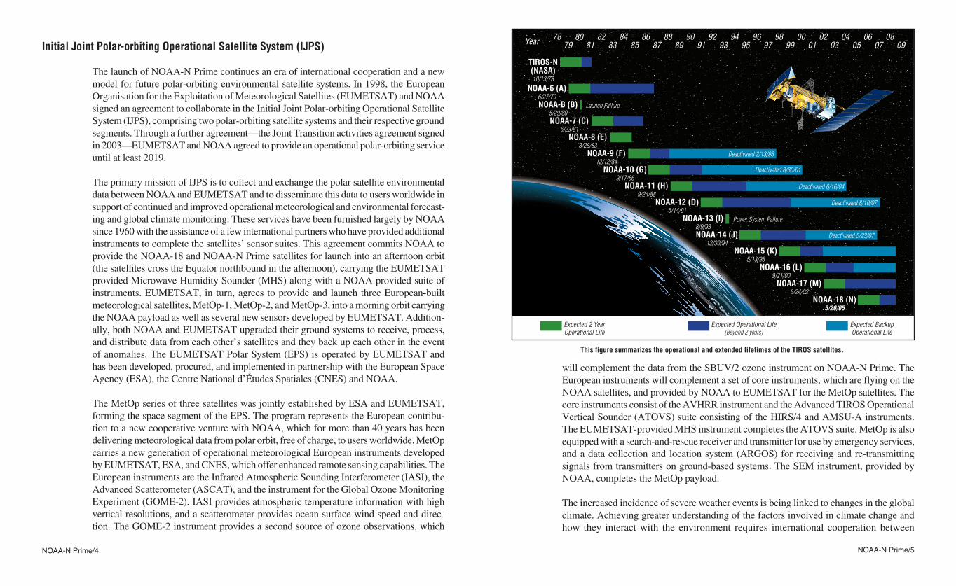
This figure summarizes the operational and extended lifetimes of the TIROS satellites.
Year
TIROS-N(NASA)10/13/78
NOAA-6 (A)6/27/79NOAA-B (B)
5/29/80Launch Failure
Power System Failure
NOAA-7 (C)6/23/81
NOAA-8 (E)3/28/83
NOAA-9 (F)12/12/84
NOAA-10 (G)9/17/86
NOAA-11 (H)9/24/88
NOAA-12 (D)5/14/91
NOAA-13 (I)8/9/93NOAA-14 (J)
12/30/94NOAA-15 (K)
5/13/98NOAA-16 (L)
9/21/00NOAA-17 (M)
6/24/02NOAA-18 (N)
5/20/05
79 9185 9704
81 9387 9906
83 9502
89 0108
0978 9084 96
0380 9286 98
0582 9488 00
07
Deactivated 2/13/98
Expected Operational Life (Beyond 2 years)
Expected 2 YearOperational Life
Expected BackupOperational Life
Deactivated 8/30/01
Deactivated 6/16/04
Deactivated 8/10/07
Deactivated 5/23/07
NOAA-N Prime/6 NOAA-N Prime/7
NOAA-N PrimeLockheed Martin Space Systems Company
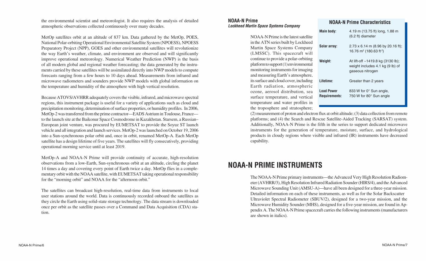
NOAA-N Prime is the latest satellite in the ATN series built by Lockheed Martin Space Systems Company (LMSSC)� This spacecraft will continue to provide a polar-orbiting platform to support (1) environmental monitoring instruments for imaging and measuring Earth’s atmosphere, its surface and cloud cover, including Earth radiation, atmospheric ozone, aerosol distribution, sea surface temperature, and vertical temperature and water profiles in the troposphere and stratosphere; (2) measurement of proton and electron flux at orbit altitude; (3) data collection from remote platforms; and (4) the Search and Rescue Satellite-Aided Tracking (SARSAT) system� Additionally, NOAA-N Prime is the fifth in the series to support dedicated microwave instruments for the generation of temperature, moisture, surface, and hydrological products in cloudy regions where visible and infrared (IR) instruments have decreased capability�
NOAA-N PRIME INSTRUMENTSThe NOAA-N Prime primary instruments —the Advanced Very High Resolution Radiom-eter (AVHRR/3), High Resolution Infrared Radiation Sounder (HIRS/4), and the Advanced Microwave Sounding Unit (AMSU-A)—have all been designed for a three-year mission� Detailed information on each of these instruments, as well as for the Solar BackscatterUltraviolet Spectral Radiometer (SBUV/2), designed for a two-year mission, and the Microwave Humidity Sounder (MHS), designed for a five-year mission, are found in Ap-pendix A� The NOAA-N Prime spacecraft carries the following instruments (manufacturers are shown in italics)�
the environmental scientist and meteorologist� It also requires the analysis of detailed atmospheric observations collected continuously over many decades�
MetOp satellites orbit at an altitude of 837 km� Data gathered by the MetOp, POES, National Polar-orbiting Operational Environmental Satellite System (NPOESS), NPOESS Preparatory Project (NPP), GOES and other environmental satellites will revolutionize the way Earth’s weather, climate, and environment are observed and will significantly improve operational meteorology� Numerical Weather Prediction (NWP) is the basis of all modern global and regional weather forecasting; the data generated by the instru-ments carried by these satellites will be assimilated directly into NWP models to compute forecasts ranging from a few hours to 10 days ahead� Measurements from infrared and microwave radiometers and sounders provide NWP models with global information on the temperature and humidity of the atmosphere with high vertical resolution�
Because ATOVS/AVHRR adequately covers the visible, infrared, and microwave spectral regions, this instrument package is useful for a variety of applications such as cloud and precipitation monitoring, determination of surface properties, or humidity profiles� In 2006, MetOp-2 was transferred from the prime contractor—EADS Astrium in Toulouse, France—to the launch site at the Baikonur Space Cosmodrome in Kazakhstan� Starsem, a Russian–European joint venture, was procured by EUMETSAT to provide the Soyuz ST launch vehicle and all integration and launch services� MetOp-2 was launched on October 19, 2006 into a Sun-synchronous polar orbit and, once in orbit, renamed MetOp-A� Each MetOp satellite has a design lifetime of five years� The satellites will fly consecutively, providing operational morning service until at least 2019�
MetOp-A and NOAA-N Prime will provide continuity of accurate, high-resolution observations from a low-Earth, Sun-synchronous orbit at an altitude, circling the planet 14 times a day and covering every point of Earth twice a day� MetOp flies in a comple-mentary orbit with the NOAA satellite, with EUMETSAT taking operational responsibility for the “morning orbit” and NOAA for the “afternoon orbit�”
The satellites can broadcast high-resolution, real-time data from instruments to local user stations around the world� Data is continuously recorded onboard the satellites as they circle the Earth using solid-state storage technology� The data stream is downloaded once per orbit as the satellite passes over a Command and Data Acquisition (CDA) sta-tion�
4.19 m (13.75 ft) long, 1.88 m (6.2 ft) diameter
2.73 x 6.14 m (8.96 by 20.16 ft); 16.76 m2 (180.63 ft 2)
At lift-off ~1419.8 kg (3130 lb); weight includes 4.1 kg (9 lb) of gaseous nitrogen
Greater than 2 years
833 W for 0° Sun angle, 750 W for 80° Sun angle
NOAA-N Prime Characteristics
Main body:
Solar array:
Weight:
Lifetime:
Load Power Requirements:
NOAA-N Prime/8 NOAA-N Prime/9
while the optical radiation passing through the 20 spectral filters is sampled� Each Earth scan takes 6�4 s and covers +49�5° from nadir� IR calibration of the HIRS/4 is provided by views of space and the internal warm target, each viewed once per 38 Earth scans�
The instrument measures scene radiance in the IR spectrum� Data from the instrument is used, in conjunction with the AMSU-A instrument, to calculate the atmosphere’s vertical temperature profile from Earth’s surface to about 40 km (24�9 mi) altitude� The data is also used to determine ocean surface temperatures, total atmospheric ozone levels, water, cloud height and coverage, and surface radiance� The visible channel is used to detect clouds�
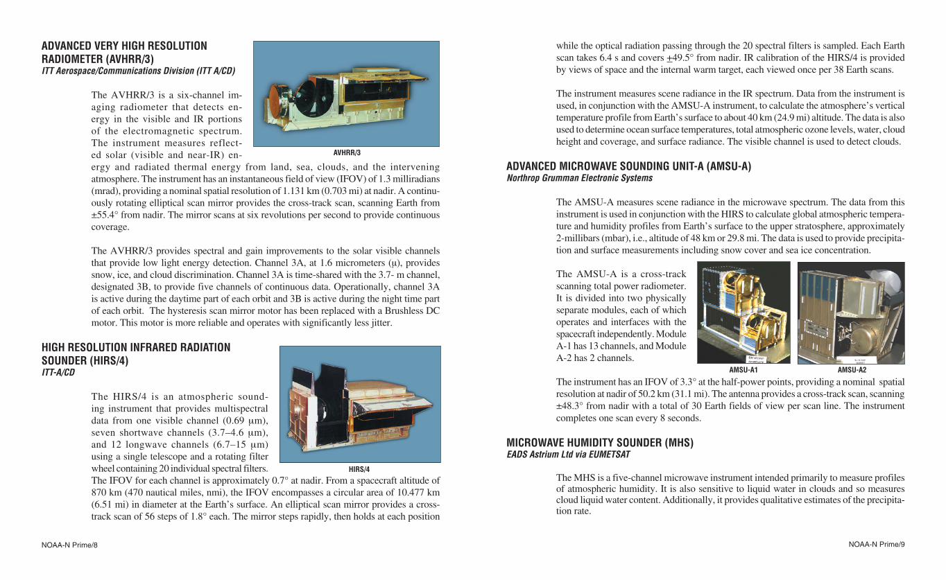
ADVANCED MICROWAVE SOUNDING UNIT-A (AMSU-A) Northrop Grumman Electronic Systems
The AMSU-A measures scene radiance in the microwave spectrum� The data from this instrument is used in conjunction with the HIRS to calculate global atmospheric tempera-ture and humidity profiles from Earth’s surface to the upper stratosphere, approximately 2-millibars (mbar), i�e�, altitude of 48 km or 29�8 mi� The data is used to provide precipita-tion and surface measurements including snow cover and sea ice concentration�
The AMSU-A is a cross-track scanning total power radiometer� It is divided into two physically separate modules, each of which operates and interfaces with the spacecraft independently� Module A-1 has 13 channels, and Module A-2 has 2 channels�
The instrument has an IFOV of 3�3° at the half-power points, providing a nominal spatial resolution at nadir of 50�2 km (31�1 mi)� The antenna provides a cross-track scan, scanning ±48�3° from nadir with a total of 30 Earth fields of view per scan line� The instrument completes one scan every 8 seconds�
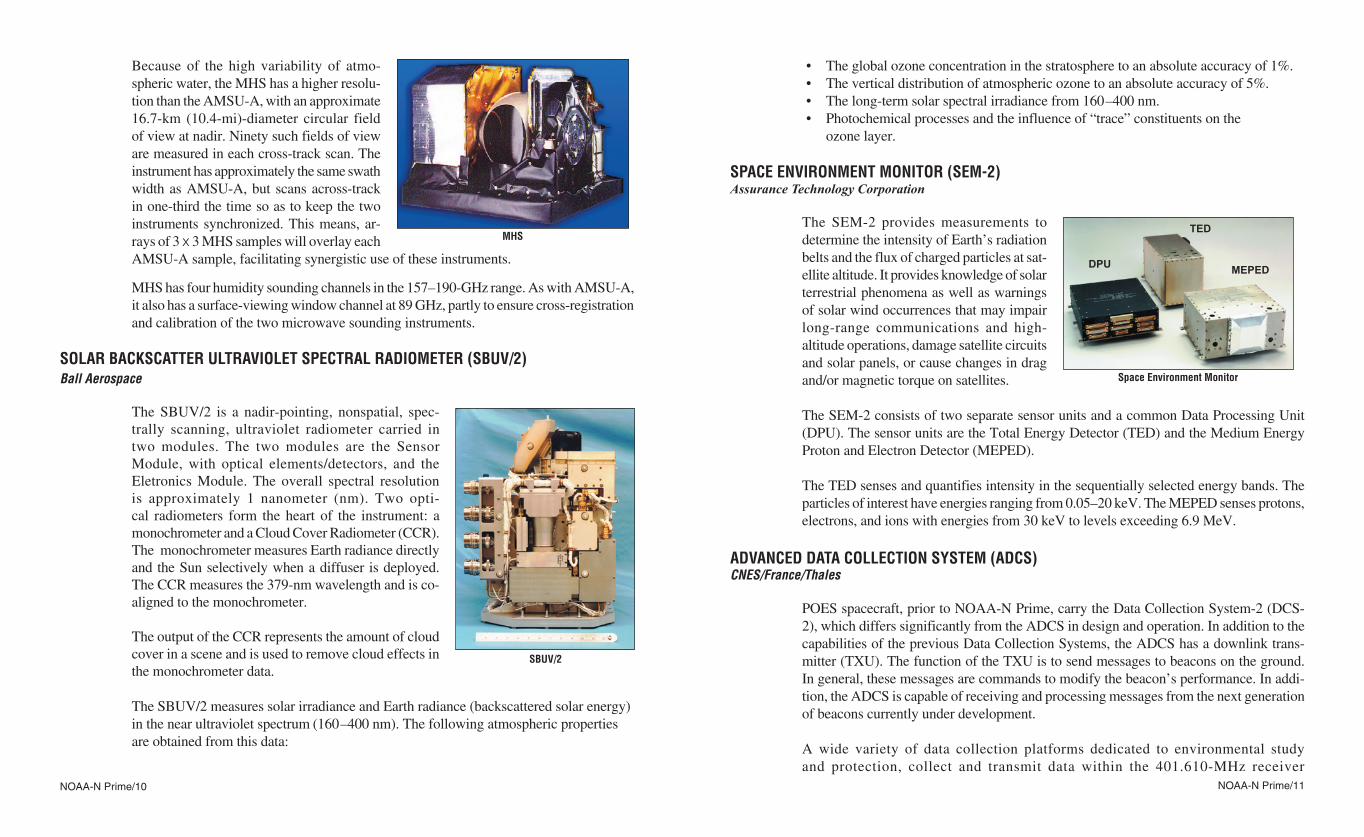
MICROWAVE HUMIDITY SOUNDER (MHS)EADS Astrium Ltd via EUMETSAT
The MHS is a five-channel microwave instrument intended primarily to measure profiles of atmospheric humidity� It is also sensitive to liquid water in clouds and so measures cloud liquid water content� Additionally, it provides qualitative estimates of the precipita-tion rate�
ADVANCED VERY HIGH RESOLUTION RADIOMETER (AVHRR/3)ITT Aerospace/Communications Division (ITT A/CD)
The AVHRR/3 is a six-channel im-aging radiometer that detects en-ergy in the visible and IR portions of the electromagnetic spectrum� The instrument measures reflect-ed solar (visible and near-IR) en-ergy and radiated thermal energy from land, sea, clouds, and the intervening atmosphere� The instrument has an instantaneous field of view (IFOV) of 1�3 milliradians (mrad), providing a nominal spatial resolution of 1�131 km (0�703 mi) at nadir� A continu-ously rotating elliptical scan mirror provides the cross-track scan, scanning Earth from ±55�4° from nadir� The mirror scans at six revolutions per second to provide continuous coverage�
The AVHRR/3 provides spectral and gain improvements to the solar visible channels that provide low light energy detection� Channel 3A, at 1�6 micrometers (µ), provides snow, ice, and cloud discrimination� Channel 3A is time-shared with the 3�7-⎧m channel, designated 3B, to provide five channels of continuous data� Operationally, channel 3A is active during the daytime part of each orbit and 3B is active during the night time part of each orbit� The hysteresis scan mirror motor has been replaced with a Brushless DC motor� This motor is more reliable and operates with significantly less jitter�
HIGH RESOLUTION INFRARED RADIATION SOUNDER (HIRS/4) ITT-A/CD
The HIRS/4 is an atmospheric sound-ing instrument that provides multispectral data from one visible channel (0�69 μm), seven shortwave channels (3�7–4�6 μm), and 12 longwave channels (6�7–15 μm) using a single telescope and a rotating filter wheel containing 20 individual spectral filters� The IFOV for each channel is approximately 0�7° at nadir� From a spacecraft altitude of 870 km (470 nautical miles, nmi), the IFOV encompasses a circular area of 10�477 km (6�51 mi) in diameter at the Earth’s surface� An elliptical scan mirror provides a cross-track scan of 56 steps of 1�8° each� The mirror steps rapidly, then holds at each position
AVHRR/3
AMSU-A1 AMSU-A2
HIRS/4
NOAA-N Prime/10 NOAA-N Prime/11
• Theglobalozoneconcentrationinthestratospheretoanabsoluteaccuracyof1%.• Theverticaldistributionofatmosphericozonetoanabsoluteaccuracyof5%.• Thelong-termsolarspectralirradiancefrom160–400nm.• Photochemicalprocessesandtheinfluenceof“trace”constituentsonthe
ozone layer�
SPACE ENVIRONMENT MONITOR (SEM-2)Assurance Technology Corporation
The SEM-2 provides measurements to determine the intensity of Earth’s radiation belts and the flux of charged particles at sat-ellite altitude� It provides knowledge of solar terrestrial phenomena as well as warnings of solar wind occurrences that may impair long-range com mu n ications and high-altitude operations, damage satellite circuits and solar panels, or cause changes in drag and/or magnetic torque on satellites�
The SEM-2 consists of two separate sensor units and a common Data Processing Unit (DPU)� The sensor units are the Total Energy Detector (TED) and the Medium Energy Proton and Electron Detector (MEPED)�
The TED senses and quantifies intensity in the sequentially selected energy bands� The particles of interest have energies ranging from 0�05–20 keV� The MEPED senses protons, electrons, and ions with energies from 30 keV to levels exceeding 6�9 MeV�
ADVANCED DATA COLLECTION SYSTEM (ADCS)CNES/France/Thales
POES spacecraft, prior to NOAA-N Prime, carry the Data Collection System-2 (DCS-2), which differs significantly from the ADCS in design and operation� In addition to the capabilities of the previous Data Collection Systems, the ADCS has a downlink trans-mitter (TXU)� The function of the TXU is to send messages to beacons on the ground� In general, these messages are commands to modify the beacon’s performance� In addi-tion, the ADCS is capable of receiving and processing messages from the next generation of beacons currently under development�
A wide variety of data collection platforms dedicated to environmental study and protection, collect and transmit data within the 401�610-MHz receiver
Because of the high variability of atmo-spheric water, the MHS has a higher resolu-tion than the AMSU-A, with an approximate 16�7-km (10�4-mi)-diameter circular field of view at nadir� Ninety such fields of view are measured in each cross-track scan� The instrument has approximately the same swath width as AMSU-A, but scans across-track in one-third the time so as to keep the two instruments synchronized� This means, ar-rays of 3 x 3 MHS samples will overlay each AMSU-A sample, facilitating synergistic use of these instruments�
MHS has four humidity sounding channels in the 157–190-GHz range� As with AMSU-A, it also has a surface-viewing window channel at 89 GHz, partly to ensure cross-registration and calibration of the two microwave sounding instruments�
SOLAR BACKSCATTER ULTRAVIOLET SPECTRAL RADIOMETER (SBUV/2)Ball Aerospace
The SBUV/2 is a nadir-pointing, nonspatial, spec-trally scanning, ultraviolet radiometer carried in two modules� The two modules are the Sensor Module, with optical elements/detectors, and the Eletronics Module� The overall spectral resolution is approximately 1 nanometer (nm)� Two opti-cal radiometers form the heart of the instrument: a monochrometer and a Cloud Cover Radiometer (CCR)� The monochrometer measures Earth radiance directly and the Sun selectively when a diffuser is deployed� The CCR measures the 379-nm wavelength and is co-aligned to the monochrometer�
The output of the CCR represents the amount of cloud cover in a scene and is used to remove cloud effects in the monochrometer data�
The SBUV/2 measures solar irradiance and Earth radiance (backscattered solar energy) in the near ultraviolet spectrum (160–400 nm)� The following atmospheric properties are obtained from this data:
TED
MEPEDDPU
Space Environment Monitor
SBUV/2
MHS
NOAA-N Prime/12 NOAA-N Prime/13
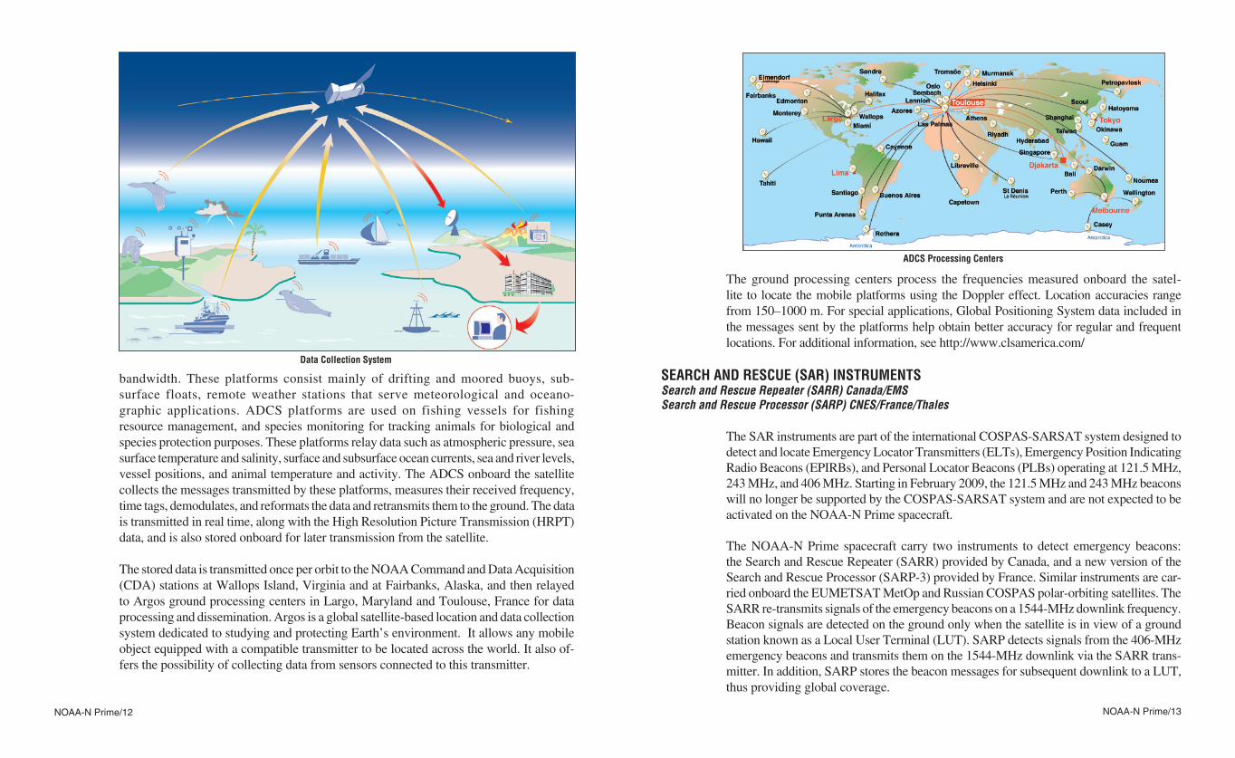
The ground processing centers process the frequencies measured onboard the satel-lite to locate the mobile platforms using the Doppler effect� Location accuracies range from 150–1000 m� For special applications, Global Positioning System data included in the messages sent by the platforms help obtain better accuracy for regular and frequent locations� For additional information, see http://www�clsamerica�com/
SEARCH AND RESCUE (SAR) INSTRUMENTSSearch and Rescue Repeater (SARR) Canada/EMSSearch and Rescue Processor (SARP) CNES/France/Thales
The SAR instruments are part of the international COSPAS-SARSAT system designed to detect and locate Emergency Locator Transmitters (ELTs), Emergency Position Indicating Radio Beacons (EPIRBs), and Personal Locator Beacons (PLBs) operating at 121�5 MHz, 243 MHz, and 406 MHz� Starting in February 2009, the 121�5 MHz and 243 MHz beacons will no longer be supported by the COSPAS-SARSAT system and are not expected to be activated on the NOAA-N Prime spacecraft�
The NOAA-N Prime spacecraft carry two instruments to detect emergency beacons: the Search and Rescue Repeater (SARR) provided by Canada, and a new version of the Search and Rescue Processor (SARP-3) provided by France� Similar instruments are car-ried onboard the EUMETSAT MetOp and Russian COSPAS polar-orbiting satellites� The SARR re-transmits signals of the emergency beacons on a 1544-MHz downlink frequency� Beacon signals are detected on the ground only when the satellite is in view of a ground station known as a Local User Terminal (LUT)� SARP detects signals from the 406-MHz emergency beacons and transmits them on the 1544-MHz downlink via the SARR trans-mitter� In addition, SARP stores the beacon messages for subsequent downlink to a LUT, thus providing global coverage�
bandwidth� These platforms consist mainly of drifting and moored buoys, sub-surface floats, remote weather stations that serve meteorological and oceano-graphic applications� ADCS platforms are used on fishing vessels for fishing resource management, and species monitoring for tracking animals for biological and species protection purposes� These platforms relay data such as atmospheric pressure, sea surface temperature and salinity, surface and subsurface ocean currents, sea and river levels, vessel positions, and animal temperature and activity� The ADCS onboard the satellite collects the messages transmitted by these platforms, measures their received frequency, time tags, demodulates, and reformats the data and retransmits them to the ground� The data is transmitted in real time, along with the High Resolution Picture Transmission (HRPT) data, and is also stored onboard for later transmission from the satellite�
The stored data is transmitted once per orbit to the NOAA Command and Data Acquisition (CDA) stations at Wallops Island, Virginia and at Fairbanks, Alaska, and then relayed to Argos ground processing centers in Largo, Maryland and Toulouse, France for data processing and dissemination� Argos is a global satellite-based location and data collection system dedicated to studying and protecting Earth’s environment� It allows any mobile object equipped with a compatible transmitter to be located across the world� It also of-fers the possibility of collecting data from sensors connected to this transmitter�
ADCS Processing Centers
Data Collection System
NOAA-N Prime/14 NOAA-N Prime/15
DIGITAL DATA RECORDER (DDR)L-3 Communications
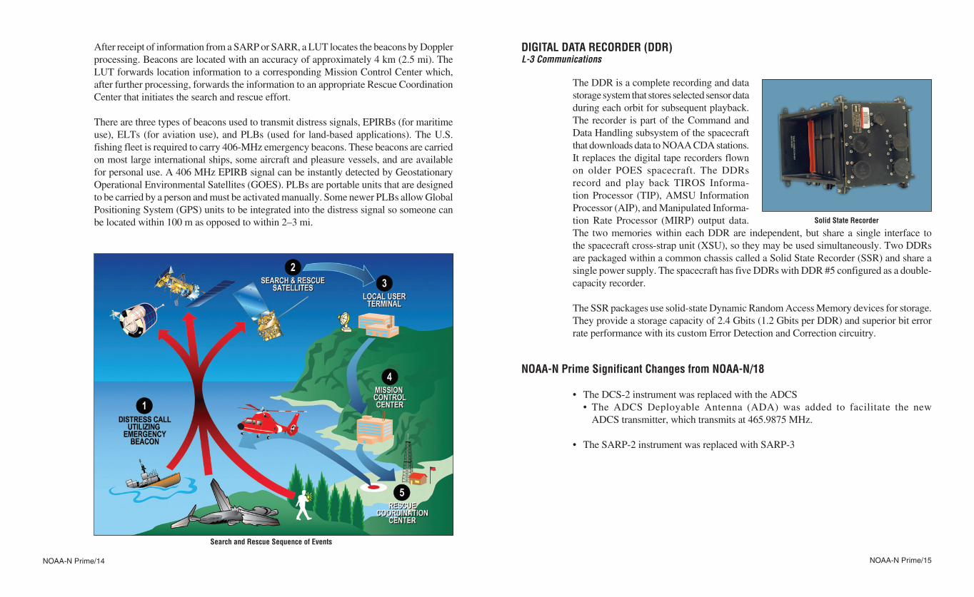
The DDR is a complete recording and data storage system that stores selected sensor data during each orbit for subsequent playback� The recorder is part of the Command and Data Handling subsystem of the spacecraft that downloads data to NOAA CDA stations� It replaces the digital tape recorders flown on older POES spacecraft� The DDRs record and play back TIROS Informa-tion Processor (TIP), AMSU Information Processor (AIP), and Manipulated Informa-tion Rate Processor (MIRP) output data� The two memories within each DDR are independent, but share a single interface to the spacecraft cross-strap unit (XSU), so they may be used simultaneously� Two DDRs are packaged within a common chassis called a Solid State Recorder (SSR) and share a single power supply� The spacecraft has five DDRs with DDR #5 configured as a double-capacity recorder�
The SSR packages use solid-state Dynamic Random Access Memory devices for storage� They provide a storage capacity of 2�4 Gbits (1�2 Gbits per DDR) and superior bit error rate performance with its custom Error Detection and Correction circuitry�
NOAA-N Prime Significant Changes from NOAA-N/18
• TheDCS-2instrumentwasreplacedwiththeADCS • The ADCS Deployable Antenna (ADA) was added to facilitate the new ADCS transmitter, which transmits at 465�9875 MHz� • TheSARP-2instrumentwasreplacedwithSARP-3
After receipt of information from a SARP or SARR, a LUT locates the beacons by Doppler processing� Beacons are located with an accuracy of approximately 4 km (2�5 mi)� The LUT forwards location information to a corresponding Mission Control Center which, after further processing, forwards the information to an appropriate Rescue Coordination Center that initiates the search and rescue effort�
There are three types of beacons used to transmit distress signals, EPIRBs (for maritime use), ELTs (for aviation use), and PLBs (used for land-based applications)� The U�S� fishing fleet is required to carry 406-MHz emergency beacons� These beacons are carried on most large international ships, some aircraft and pleasure vessels, and are available for personal use� A 406 MHz EPIRB signal can be instantly detected by Geostationary Operational Environmental Satellites (GOES)� PLBs are portable units that are designed to be carried by a person and must be activated manually� Some newer PLBs allow Global Positioning System (GPS) units to be integrated into the distress signal so someone can be located within 100 m as opposed to within 2–3 mi�
Search and Rescue Sequence of Events
Solid State Recorder
NOAA-N Prime/16 NOAA-N Prime/17
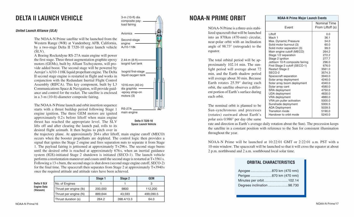
DELTA II LAUNCH VEHICLE
United Launch Alliance (ULA)
The NOAA-N Prime satellite will be launched from the Western Range (WR) at Vandenberg AFB, California, by a two-stage Delta II 7320-10 space launch vehicle (SLV)�A Boeing Rocketdyne RS-27A main engine will power the first stage� Three thrust augmentation graphite epoxy motors (GEMs), built by Alliant Techsystems, will pro-vide added boost� The second stage will be powered by Aerojet’s AJ10-118K liquid propellant engine� The Delta II second stage engine is restarted in flight and works in conjunction with the Redundant Inertial Flight Control Assembly (RIFCA)� This key component, built by L3 Communications Space & Navigation, will provide guid-ance and control for the rocket� The satellite is enclosed in a 3-m (10-ft)-diameter composite fairing�
The NOAA-N Prime launch and orbit insertion sequence starts with a thrust buildup period following Stage 1 engine ignition� The three GEM motors are ignited approximately 0�2 s before liftoff when main engine thrust has reached the appropriate level� The SLV lifts off and after clearing the launch pad, rolls to its desired flight azimuth� It then begins to pitch over in the trajectory plane� At approximately 264 s after liftoff, main engine cutoff (MECO) occurs when the booster propellants are depleted� The control logic then provides a signal that ignites the Stage 2 engine and fires separation nuts to separate it from Stage 1� The payload fairing is jettisoned at approximately T+296 s� The second stage burns until the desired orbit is reached at approximately 676 s, when an inertial guidance system (IGS)-initiated Stage 2 shutdown is initiated (SECO-1)� The launch vehicle performs a reorientation maneuver and coasts until the second stage is restarted at T+3561 s� Following a 13-s burn, the second stage is shut down (second stage engine cutoff, SECO-2) for the final time� The spacecraft then separates from Stage 2 at approximately T+3940 s once the required attitude and attitude rates have been achieved�
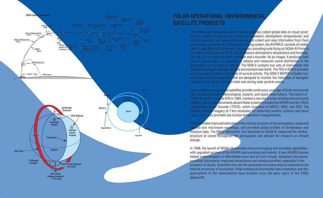
NOAA-N PRIME ORBITNOAA-N Prime is a three-axis stabi-lized spacecraft that will be launched into an 870 km (470-nmi) circular, near-polar orbit with an inclination angle of 98�73° (retrograde) to the equator�
The total orbital period will be ap-proximately 102�14 min� The sun-light period will average about 72 min, and the Earth shadow period will average about 30 min� Because Earth rotates 25�59° during each orbit, the satellite observes a differ-ent portion of Earth’s surface during each orbit�
The nominal orbit is planned to be Sun-synchronous and precesses (rotates) eastward about Earth’s polar axis 0�986° per day (the same rate and direction as Earth’s average daily rotation about the Sun)� The precession keeps the satellite in a constant position with reference to the Sun for consistent illumination throughout the year�
NOAA-N Prime will be launched at 10:22:01 GMT or 2:22:01 a�m� PST with a 10-min window� The spacecraft will be launched so that it will cross the equator at about 2 p�m� northbound and 2 a�m� southbound local solar time�
Delta II 7320-10 Space Launch Vehicle
3-m (10-ft) dia composite pay-load fairing
Avionics
Second-stage engineAJ10-118k
2.44-m (8-ft) isogrid fuel tank
Isogrid first-stage liquid oxygen tank
1016-mm (40-in)dia graphite -epoxy strap-on motors (3)
RS-27A main engine
Delta II SLV Engine Data (Vacuum)
Stage 1 Stage 2 GEM
No. of Engines 1 1 3
Thrust per engine (lb) 200,000 9800 112,200
Thrust per engine (N) 889,644 43,593 499,090.5
Thrust duration (s) 264.2 398.4/13.3 64.0
Liftoff 0.0Mach 1 36.1Max. Dynamic Pressure 54.0Solid motor burnout (3) 60.0Solid motor separation (3) 99.0Main engine cutoff (MECO) 264.2Stage 1/2 separation 272.2Stage 2 ignition 277.7Jettison 10-ft composite fairing 296.0First Stage 2 cutoff (SECO-1) 676.0 Restart Stage 2 3561.0SECO-2 3574.3Spacecraft separation 3940.0Solar array deployment 4240.0Solar array boom deployment 4340.0Solar array cant 4580.0SRA deployment 4750.0UDA deployment 4830.0VRA deployment 4880.0VRA pin puller activation 5000.0Sunshade deployment 5000.5ADA Deployment 5039.5Transition mode 5190.0Handover to orbit mode 5240.0
EventNominal Time From Liftoff (s)
NOAA-N Prime Major Launch Events
ORBITAL CHARACTERISTICS
Apogee ......................870 km (470 nmi)Perigee ......................870 km (470 nmi)Minutes per orbit .........................102.14Degrees inclination .....................98.730
NOAA-N Prime/18 NOAA-N Prime/19
POLAR OPERATIONAL ENVIRONMENTAL SATELLITE PRODUCTS
The NOAA polar operational environmental satellites collect global data on cloud cover; surface conditions such as ice, snow, and vegetation; atmospheric temperatures; and moisture, aerosol, and ozone distributions; and collect and relay information from fixed and moving data platforms. The primary imaging system, the AVHRR/3, consists of visible, near-IR, and thermal IR channels. The primary sounding suite flying on NOAA-N Prime is the HIRS/4, AMSU-A, and MHS, which measure atmospheric temperature and humidity. The SBUV-2 instrument is both an imager and a sounder. As an imager, it produces total column ozone maps. As a sounder, it obtains and measures ozone distribution in the atmosphere as a function of altitude. The SEM-2 contains two sets of instruments that monitor the energetic charged-particle environment near Earth. The TED in SEM-2 provides the data used to determine the level of auroral activity. The SEM-2 MEPED includes four solid-state detector telescopes that are designed to monitor the intensities of energetic particles in the Earth’s radiation belts and during solar particle events.
Polar-orbiting environmental satellites provide continuous coverage of Earth and provide high-resolution global meteorological, oceanic, and space observations. The launch ofTIROS-N in 1978, and the ATN in 1983, marked a new era of polar-orbiting environmental satellites. Advanced instruments aboard these systems included the AVHRR and the TIROS Operational Vertical Sounder (TOVS), which consisted of HIRS/2, MSU, and SSU. The AVHRR provided imagery at 1-km resolution for observing weather systems and cloud cover, and it also provided sea surface temperature measurements.
TOVS provided improved estimates of the vertical structure of the atmosphere, measured infrared and microwave soundings, and provided global profiles of temperature and moisture data. The SBUV instrument, first launched on NOAA-9, measured the verticalstructure of ozone throughout the atmosphere and allowed for research on climate change.
In 1998, the launch of NOAA-15 provided improved imaging and sounding capabilitieswith upgraded versions of the AVHRR and sounding instruments. A new AVHRR channel helped meteorologists to differentiate snow and ice from clouds. Advanced microwavesounding instruments improved temperature and moisture profiles, especially in thepresence of clouds. Scientists now use the advanced microwave data to characterize the internal structures of hurricanes. Polar-orbiting environmental instrumentation and theapplications of the observations have evolved since the early years of the POES spacecraft.
Orbit Launch Sequence
S
NOAA-N Prime/20 NOAA-N Prime/21
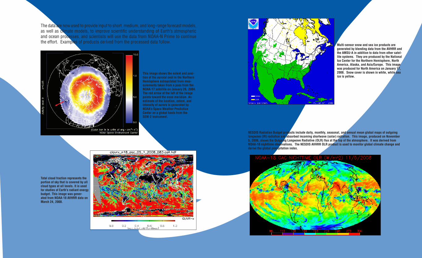
The data are now used to provide input to short, medium, and long-range forecast models, as well as climate models, to improve scientific understanding of Earth’s atmospheric and ocean processes, and scientists will use the data from NOAA-N Prime to continue the effort. Examples of products derived from the processed data follow.
This image shows the extent and posi-tion of the auroral oval in the Northern Hemisphere extrapolated from mea-surements taken from a pass from the NOAA-17 satellite on January 26, 2004. The red arrow at the left of the image points toward the noon meridian. An estimate of the location, extent, and intensity of aurora is generated by NOAA’s Space Weather Prediction Center on a global basis from the SEM-2 instrument.
Total cloud fraction represents the portion of sky that is covered by all cloud types at all levels. It is used for studies of Earth’s radiant energy budget. This image was gener-ated from NOAA-18 AVHRR data on March 24, 2008.
Multi-sensor snow and sea ice products are generated by blending data from the AVHRR and the AMSU-A in addition to data from other satel-lite systems. They are produced by the National Ice Center for the Northern Hemisphere, North America, Alaska, and Asia/Europe. This image was produced for North America on January 17, 2008. Snow cover is shown in white, while sea ice is yellow.
NESDIS Radiation Budget products include daily, monthly, seasonal, and annual mean global maps of outgoing longwave (IR) radiation and absorbed incoming shortwave (solar) radiation. This image, produced on November 5, 2008, shows the Outgoing Longwave Radiative (OLR) flux at the top of the atmosphere. It was derived from NOAA-18 nighttime observations. The NESDIS AVHRR OLR product is used to monitor global climate change and derive the global precipitation index.
NOAA-N Prime/22 NOAA-N Prime/23
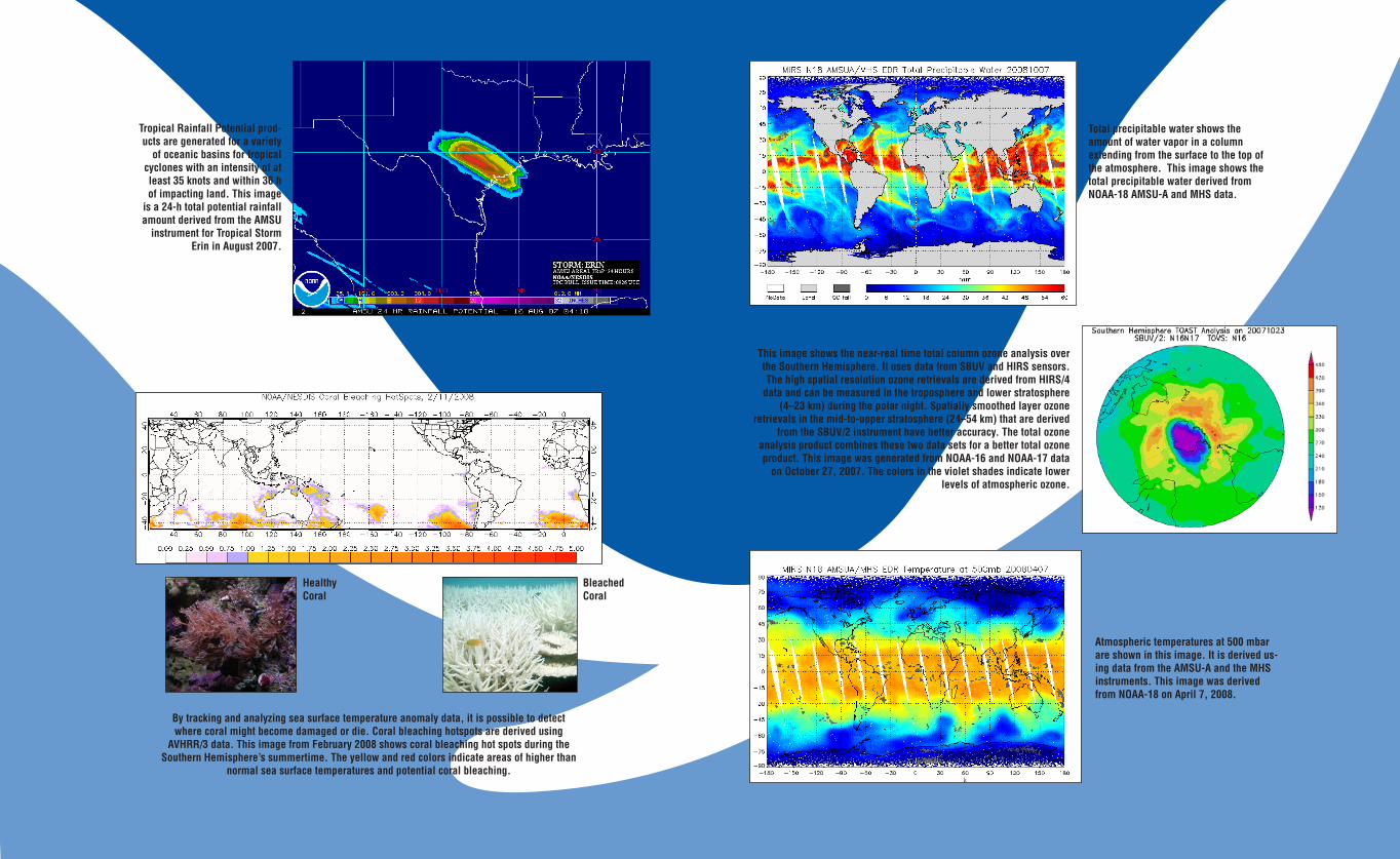
This image shows the near-real time total column ozone analysis over the Southern Hemisphere. It uses data from SBUV and HIRS sensors. The high spatial resolution ozone retrievals are derived from HIRS/4
data and can be measured in the troposphere and lower stratosphere (4–23 km) during the polar night. Spatially smoothed layer ozone
retrievals in the mid-to-upper stratosphere (24–54 km) that are derived from the SBUV/2 instrument have better accuracy. The total ozone
analysis product combines these two data sets for a better total ozone product. This image was generated from NOAA-16 and NOAA-17 data
on October 27, 2007. The colors in the violet shades indicate lower levels of atmospheric ozone.
Atmospheric temperatures at 500 mbar are shown in this image. It is derived us-ing data from the AMSU-A and the MHS instruments. This image was derived from NOAA-18 on April 7, 2008.
HealthyCoral
BleachedCoral
Tropical Rainfall Potential prod-ucts are generated for a variety
of oceanic basins for tropical cyclones with an intensity of at least 35 knots and within 36 h of impacting land. This image
is a 24-h total potential rainfall amount derived from the AMSU
instrument for Tropical Storm Erin in August 2007.
By tracking and analyzing sea surface temperature anomaly data, it is possible to detect where coral might become damaged or die. Coral bleaching hotspots are derived using
AVHRR/3 data. This image from February 2008 shows coral bleaching hot spots during the Southern Hemisphere’s summertime. The yellow and red colors indicate areas of higher than
normal sea surface temperatures and potential coral bleaching.
Total precipitable water shows the amount of water vapor in a column extending from the surface to the top of the atmosphere. This image shows the total precipitable water derived from NOAA-18 AMSU-A and MHS data.
NOAA-N Prime/24 NOAA-N Prime/25
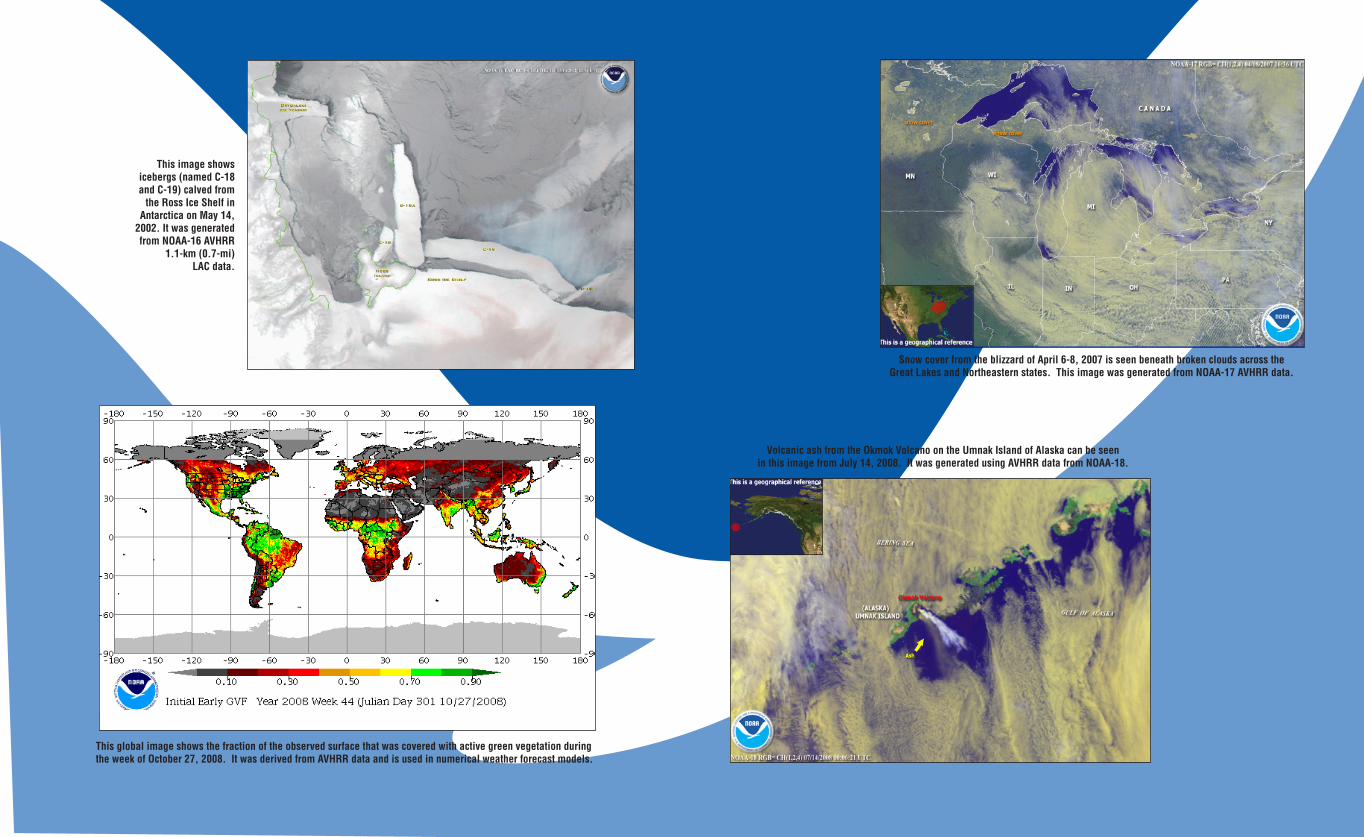
This image shows icebergs (named C-18 and C-19) calved from
the Ross Ice Shelf in Antarctica on May 14,
2002. It was generated from NOAA-16 AVHRR
1.1-km (0.7-mi) LAC data.
This global image shows the fraction of the observed surface that was covered with active green vegetation during the week of October 27, 2008. It was derived from AVHRR data and is used in numerical weather forecast models.
Volcanic ash from the Okmok Volcano on the Umnak Island of Alaska can be seen in this image from July 14, 2008. It was generated using AVHRR data from NOAA-18.
Snow cover from the blizzard of April 6-8, 2007 is seen beneath broken clouds across the Great Lakes and Northeastern states. This image was generated from NOAA-17 AVHRR data.
NOAA-N Prime/26 NOAA-N Prime/27
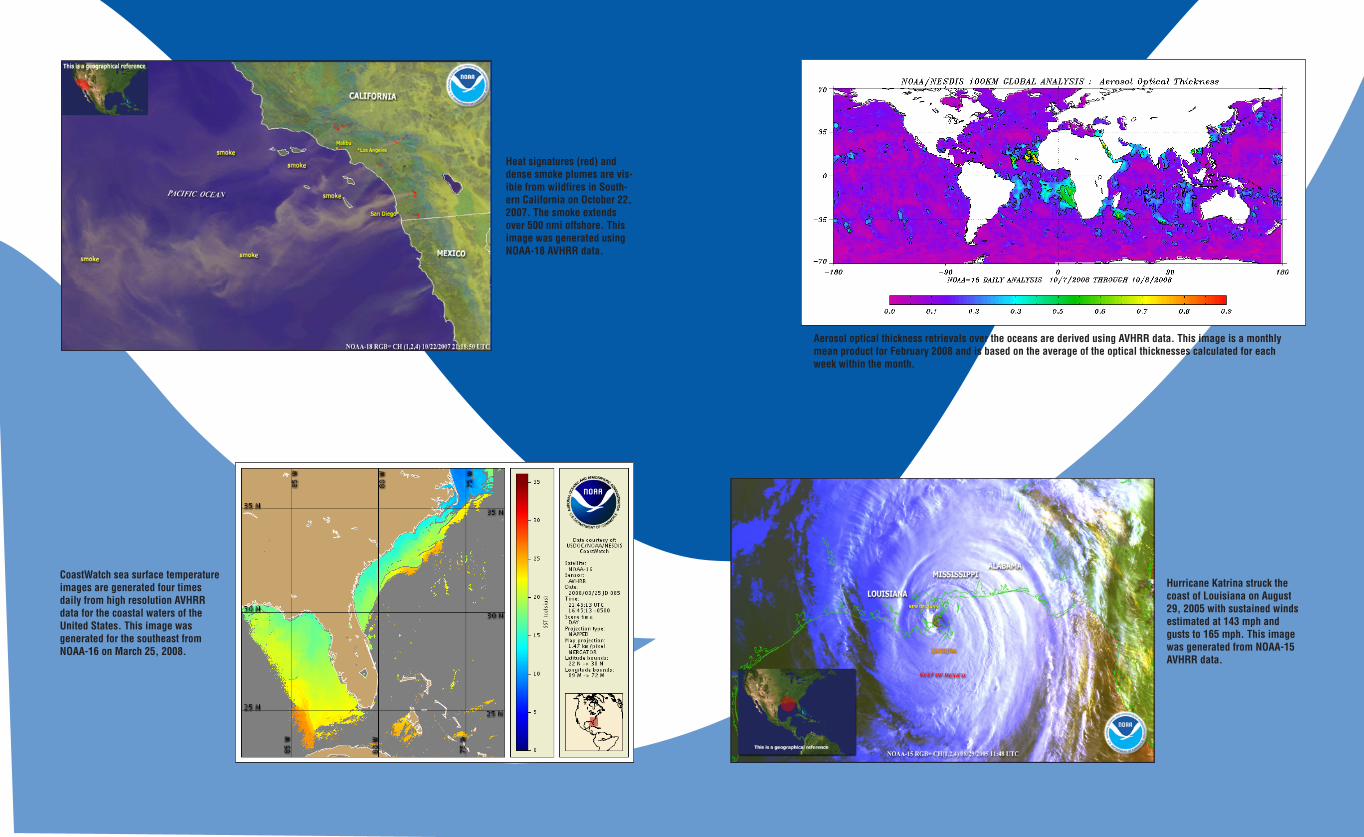
Heat signatures (red) and dense smoke plumes are vis-ible from wildfires in South-ern California on October 22, 2007. The smoke extends over 500 nmi offshore. This image was generated using NOAA-18 AVHRR data.
CoastWatch sea surface temperature images are generated four times daily from high resolution AVHRR data for the coastal waters of the United States. This image was generated for the southeast from NOAA-16 on March 25, 2008.
Aerosol optical thickness retrievals over the oceans are derived using AVHRR data. This image is a monthly mean product for February 2008 and is based on the average of the optical thicknesses calculated for each week within the month.
Hurricane Katrina struck the coast of Louisiana on August 29, 2005 with sustained winds estimated at 143 mph and gusts to 165 mph. This image was generated from NOAA-15 AVHRR data.
NOAA-N Prime/28 NOAA-N Prime/29
SPACECRAFT DATA COMMUNICATIONSThe spacecraft transmits instrument data to the ground for three primary functions: Data Acquisition, Direct Broadcast, and Search and Rescue�
COMMAND AND DATA ACQUISITION (CDA) STATION DOWNLINKS
NOAA CDA stations located at Fairbanks, Alaska, and Wallops Island, Virginia, receive stored GAC and LAC data from each spacecraft� The CDA stations can also receive real-time data when the satellites are within the direct readout footprint� EUMETSAT operates a station in Svalbard, Norway�
GAC data is recorded and contains satellite house-keep-ing information, AMSU data, and 4-km (2�5-mi)-reso-lution AVHRR imagery� GAC data contains more than 100 min (one full orbit) of imagery and is transmitted to a NOAA CDA station for relay to centralized viewers�
LAC data is recorded information that contains 1-km (0�6-mi) AVHRR imagery� LAC data is recorded for up to 10 min and transmitted to a CDA stations for relay to central-ized users�
High Resolution Picture Transmission (HRPT) is real-time transmission of instrument data and satellite housekeeping data� CDA stations intercept HRPT data primarily for satellite housekeeping data, but also relay the higher resolution data to centralized users�
DIRECT BROADCAST DOWNLINKS
For more than 30 years, NOAA has freely and openly provided satellite data through direct broadcasting to users in the United States and in 100 other countries throughout the world� In the United States, any commercial firm receiving data through direct broadcast-ing (commonly called direct readout service) may provide tailored products to customers and/or viewers�
There are three types of direct broadcasting: (1) real-time HRPT, (2) real-time very high fre-quency (VHF) beacon transmissions, and (3) Automatic Picture Transmission (APT)�
High Resolution Picture Transmission
HRPT provides worldwide direct readout of full-resolution spacecraft parameters and instrument data to ground stations within the footprint of the NOAA polar-orbiting sat-ellite� HRPT service was originally designed to provide timely day and nighttime sea surface temperature and ice, snow, and cloud cover information to diverse users, but applications have expanded because of the proliferation of moderately priced equipment and software� HRPT transmissions contain data from all instruments aboard the NOAA polar-orbiting satellites� The data stream includes information from the TIP, the AIP, and from the AVHRR/3, providing five of six channels at 1�131-km (0�703-mi) resolution� The TIP contains spacecraft attitude data, time codes, housekeeping, and low rate instrument science data from the HIRS/4, SEM-2, ADCS, and the SBUV/2� The AMSU-A and MHS are also included in HRPT from the AIP�
To receive the data, users can purchase the necessary equipment (computer, software, and antenna) from commercial companies for unlimited access to HRPT signals� In 2004, there were 663 HRPT receivers worldwide registered with the World Meteorological Organization (WMO)�
Very High Frequency (VHF) Beacon Transmission
VHF beacon transmission is available to users who do not intend to install the more com-plex equipment necessary to receive high data rate S-band service� The lower data rate from the TIP permits the user to install less complex, less costly equipment to receive the data (HIRS/4, SEM-2, ADCS, and SBUV/2, but not AMSU)�
Parallel outputs are provided for the real-time VHF beacon transmission� The instrument data is multiplexed with analog and digital housekeeping data� TIP output directly modu-lates the beacon transmission� The data is transmitted as an 8�32-kbps split phase signal over one of the beacon transmitters at 137�35 MHz or 137�77 MHz�
Automated Picture Transmission (APT) Data
APT data is smoothed 4-km (2�5-mi)-resolution IR and visible imagery derived from the AVHRR/3 instrument and transmitted within the footprint of the NOAA polar-orbiting satellite� Because APT data is captured on low-cost VHF ground stations, it is also very popular in schools� Users purchase the necessary equipment (computer, software, and
13-m Antenna at Fairbanks, Alaska
NOAA-N Prime/30 NOAA-N Prime/31
NATIONAL ENVIRONMENTAL SATELLITE, DATA, AND IN-FORMATION SERVICE (NESDIS) SATELLITE OPERATIONS CONTROL CENTER (SOCC)
The control center for satellite opera-tions is located in the NOAA Satellite Operations Facility (NSOF) at Suitland, Maryland� The SOCC is responsible for operational control of the entire ground system and the following areas:
CDA Stations —The primary CDA stations are located at Fairbanks, Alaska, and Wallops Island, Vir-ginia� A remote limited-function CDA facility, built and maintained by the NOAA Fairbanks CDA station, is located at Point Barrow, Alaska, on the Arctic Circle� Because of its high latitude, Point Barrow provides monitoring and S-band com-mand capability for the “blind orbits” not normally seen by the primary Wallops and Fairbanks CDA stations� EUMETSAT provides support from Svalbard Norway for the MetOp and POES missions�
The CDA stations transmit commands to the satellites and acquire and record environ-mental and engineering data from the satellites for retransmission to the SOCC� All data and commands are transmitted between the SOCC and the CDA stations via commercial communications links�
Ground Communications—The ground communication links for satellite operations are provided by the Satellite Communications Network (SATCOM) and NASA Integrated Services Network (NISN)� SATCOM provides all voice and data links between the SOCC and the CDA stations after launch� NISN provides launch-unique communication links for satellite launch; NESDIS provides and operates SATCOM�
antenna) from commercial companies for unlimited access to APT signals� In 2004, there were 4,945 APT receivers worldwide registered with the WMO�The Satellite Operations Control Center (SOCC) can select by command any two of the active five AVHRR/3 channels provided to the MIRP, which are further processed as “Video A” and “Video B�” One APT line, consisting of one line of Video A and one line of Video B, is output every third AVHRR scan� Ancillary AVHRR data appears at one edge of each line and their 64 sec� repetition period defines the APT frame length� The resulting line rate is 2 per sec� The data is transmitted continuously over a dedicated VHF link as an analog signal consisting of an amplitude-modulated 2400-Hz subcarrier frequency modulating the RF carrier at 137�1 MHz or 137�9125 MHz�
SEARCH AND RESCUE DOWNLINKS
For information about SAR, please refer to the previous section titled Search and Rescue Instruments�
NOAA KLMN-N Prime Spacecraft Communications Radio Frequency (RF) Links (frequencies are in MHz)
NOAA-N Prime/32 NOAA-N Prime/33
All ground attitude determination is accomplished by the NOAA ESPC�
THE NORTH AMERICAN AEROSPACE DEFENSE COMMAND (NORAD)
NORAD has prime responsibility for orbit determination, including establishment of the initial orbit solution, and providing updated orbital parameters routinely throughout the life of the mission�
LAUNCH, EARLY ORBIT, AND CONTINGENCY DOWNLINK
A 2247�5-MHz S-band downlink is used during satellite ascent to recover TIP boost telemetry through Western Range (WR) tracking sites� From launch through spacecraft separation, WR stations, mobile telemetry, McMurdo NASA Antarctic Interactive Launch Support (NAILS), and Malindi in Kenya will provide space-craft tracking and telemetry� Following spacecraft separation and through space-craft transition and handover to orbit, the GN station at Svalbard, Norway and the NOAA Fairbanks CDA facility will provide spacecraft tracking and support� The Space Network Tracking and Data Relay Satellite System (TDRSS) will provide best-effort tracking and telemetry support on a near-continuous basis from launch through spacecraft separation and handover and transition to orbit mode�
During on-orbit operations, orbit mode TIP/AIP and command capability will be available for early orbit and contingency support as follows� Command and telemetry support will be provided by the NOAA CDAs; the Universal Space Net-work (USN) operated sites at Dongara, Australia, Southpoint, Hawaii; Santiago, Chile (operated by the University of Chile), and Svalbard, Norway via the GN; and the McMurdo (NAILS) Facility in Antarctica� Telemetry support only will be provided from the NOAA Point Barrows, Alaska site� TDRSS will provide telemetry on a best-effort basis as requested by the Project�
ENVIRONMENTAL SATELLITE PROCESSING CENTER (ESPC)
The NESDIS ESPC acquires the data from the CDA stations via the SOCC and is responsible for data processing and the generation of meteorological products on a timely basis to meet POES program requirements�
OTHER SUPPORT SYSTEMS
SEARCH AND RESCUE GROUND SYSTEM
The U�S� Local User Terminals (LUTs) are located at the Command and Data Acquisition Station at Fairbanks, Alaska; Vandenberg AFB, California; the U�S� Coast Guard (USCG) Communications Station at Wahiawa, Hawaii; the USCG Communications Station at Miami, Florida; NOAA at Suitland, Maryland; and Anderson AFB, Guam�
The LUTs receive SAR data from the NOAA polar-orbiting and geosynchronous satellites and also from other low-Earth-orbiting satellites� Determines the location of any activated distress beacons, and forwards the data to the U�S� Mission Control Center (USMCC) at Suitland, Maryland� The USMCC first validates the distress situation and then determines the proper Rescue Coordination Center (RCC)� It then forwards the distress location data to the RCC after removing redundant information� Additionally, a test ground station is maintained at NASA Goddard Space Flight Center (GSFC) in Greenbelt, Maryland� This system is part of the worldwide Cospas-Sarsat Program that consists of 40 countries who participate in the management of the program: 31 of these provide MCCs and LUTs, and 9 additional countries receive the data� All MCCs cooperate in sending data to provide rapid global delivery of distress locations received through the satellites�
GODDARD SPACE FLIGHT CENTER FACILITY SUPPORT
Support associated with NASA’s Space Network (SN) and Ground Network (GN) is requested through the Detailed Mission Requirements document, with other sup-port as described in Memoranda of Under-standing� NASA GSFC provides nominal prelaunch orbital and prediction information, special support for initial orbit estimation, and initial quality control checks of North American Aerospace Defense ( NORAD) orbital data�
Svalbard StationWallops Island CDA StationGoddard Space Flight Center
NOAA-N Prime/34 NOAA-N Prime/35
NOAA-F (9) was launched December 12, 1984, into a 470-nmi (870-km) afternoon orbit. This mission tested the Earth Radiation Budget Experiment (ERBE) and the SBUV radiometer as part of the expanded capabilities of the ATN satellites, as well as carrying the instruments found on earlier ATN missions. The ERBE consisted of shortwave and longwave radiometers that were used to study Earth’s albedo in an attempt to recognize and interpret seasonal and annual climate varia-tions. The SBUV measured the vertical structure of ozone in the atmosphere. The satellite also had real-time and global SAR instruments onboard. The MSU, a primary mission sensor, failed on May 7, 1987. The Digital Tape Recorder (DTR) 1A/1B failed two months after launch. The ERBE scanner stopped outputting science data in January 1987. Earlier in the mission, the AVHRR periodically exhibited anomalous behavior in its synchronization with the MIRP. The SBUV/2 and the SSU instruments aboard continued to operate satisfactorily. The MSU channels 2 and 3 failed, and the satellite’s power system was degraded. In August 1995, a very high power overvoltage condition resulted in the failure of the MIRP, the AVHRR, the Battery #1 charge regulator, and the IMU temperature control amplifier. The MIRP failure also resulted in the loss of the global SAR data via the GAC data stream. The satellite’s ability to collect, process, and distribute SBUV/2, SSU, and ERBE-nonscanner data was now limited to stored TIP data. The SARR transmitter failed on December 18, 1997. The satellite was deactivated on February 13, 1998.
NOAA-G (10) was launched September 17, 1986, into a 450-nmi (833-km) morning orbit. It car-ried the AVHRR, HIRS/2, MSU, SSU, SEM, DCS, the SARSAT system, and ERBE. The ERBE scanner exhibited a scan-sticking anomaly that was apparently generic to the instrument. The SARP 406-MHz receiver also failed. The SARP provided global SAR data before its failure. In December 1994, the AVHRR IR channels were damaged and remained severely degraded from a satellite tumble caused by an overflow of the satellite’s ephemeris clock. NOAA-10 was placed in standby mode on September 17, 1991 (the date NOAA-12 became fully operational). In January 1997, the MSU scanner displayed anomalous readings. Telemetry indicated that the digital encoder had failed. The MSU scanner motor was commanded off in February 1997. A MIRP-related missing minor frame anomaly occurred in August 1998. The HRPT data was unusable because of an unstable MIRP and a faulty AVHRR. The satellite was de-activated on August 30, 2001.
NOAA-H (11) was launched September 24, 1988, into a 470-nmi (870-km) afternoon orbit. It carried a five-channel AVHRR, the HIRS/2, MSU, SSU, SBUV/2, SEM, DCS, and SARSAT system. The AVHRR failed on September 13, 1994. The spacecraft was modified for a 0° to 80° Sun angle and included fixed and deployable sunshades on the IMP. The increase of maximum Sun angle from 68° to 80° allowed an afternoon nodal crossing
Synopsis of Prior SpacecraftTIROS-N, paid for by NASA, was the first in the new series of satellites turned over to NOAA for operations. Subsequent, satellites were paid for by NOAA and given a letter designation while being built. Once the satellites achieved orbit they were given a number designation (indicated in this section with the number in parentheses) and were handed over to NOAA for operations after checkout by NASA. Starting with NOAA-A, it became NOAA-6 operationally. Due to the desire to get the first US provided search and rescue satellite operational, NOAA-E was launched out of sequence, before NOAA-D. After achieving orbit, NOAA-E, a larger spacecraft, was designated NOAA-11. After many years in ground storage, NOAA-D was refurbished and launched on May 14, 1991, to become NOAA-12, which provided over 16 years of service.
TIROS-N was launched October 13, 1978, into a 470-nmi (870-km) afternoon orbit. It was the first satellite in the fourth generation operational environmental satellite system. TIROS-N was a research and development spacecraft serving as a protoflight for the operational follow-on series, NOAA-A through N Prime spacecraft. The satellite was equipped with a four-channel AVHRR, HIRS, Microwave Sounding Unit (MSU), Stratospheric Sounding Unit (SSU), SEM, and DCS. TIROS-N was deactivated following an Inertial Measurement Unit (IMU) power supply failure on February 27, 1981.
NOAA-A (6) was launched June 27, 1979, into a 450-nmi (833-km) morning orbit. The satellite car-ried the four-channel AVHRR, HIRS/2, MSU, SSU, SEM, and DCS. The HIRS, a primary mission sensor, failed on September 19, 1983. The satellite greatly exceeded its two-year lifetime. It was totally deactivated on March 31, 1987, after nearly eight years of operational service.
NOAA-B was launched May 29, 1980. It failed to achieve a usable orbit because of a booster engine anomaly.
NOAA-C (7) was launched June 23, 1981, into a 470-nmi (870-km) afternoon orbit. It carried a five-channel AVHRR, rather than the four-channel AVHRR that flew on earlier spacecraft. Other instruments were the HIRS/2, MSU, SSU, SEM, and DCS. The HIRS, a primary mission sensor, failed on February 7, 1985. The satellite was deactivated on June 7, 1986, following a failure in the power system.
NOAA-E (8) was launched March 28, 1983, into a 450-nmi (833-km) morning orbit. It was the first of the ATN satellites and included a stretched structure to provide growth capability. It also included the first search and rescue package. In addition, the spacecraft carried a four-channel AVHRR, HIRS/2, MSU, SSU, SEM, and DCS. The redundant crystal oscillator (RXO) failed after 14 months in orbit. The RXO recovered from its failure, finally locking up on the backup RXO in May 1985. The satellite was stabilized and declared operational by NOAA on July 1, 1985. The NOAA-8 spacecraft was finally lost on December 29, 1985, following a thermal runaway that destroyed a battery.
NOAA-11 was launched on September 24, 1988. It was
deactivated in June 2004 after completing more than
81,000 orbits.

NOAA-N Prime/36 NOAA-N Prime/37
Recovery operations were successful and the unit resumed operations on November 28, 2003. NOAA-14 was deactivated on May 23, 2007 after more than 12 years of service.
NOAA-K (15) was launched May 13, 1998, into a 450-nmi (833-km) morning orbit. It replaced NOAA-12 on December 14, 1998, as the primary morning spacecraft. It is currently a morning backup satellite. NOAA-K was the first in the ATN series to support dedicated microwave instruments for the generation of temperature, moisture, surface, and hydrological products where visible and IR instruments have decreased capability. NOAA-K replaced the MSU of earlier spacecraft with the AMSU-A and AMSU-B instruments. It also carries a six-channel AVHRR/3, a HIRS/3 and SEM/2, a SARSAT system, and a DCS. The S-band transmitter (STX)-1, STX-2, and STX-3 high-gain antennas have shown degraded performance in orbit. Beginning September 28, 1999, the satellite was configured to transmit HRPT using the STX-2 omnidirectional antenna and transmit data playbacks using STX-4. The STX-1 and STX-3 downlinks are not used. Since launch, the AMSU-B instrument has had a bias in the science data that was corrected by software processing on the ground. This bias was caused by interference from onboard L-band and S-band transmit systems. With the use of the omnidirectional antennas and only the STX-2 and STX-4 downlinks, the interference was modeled to remove the bias to the science data. AMSU-B instruments on NOAA-16 and later spacecraft were modified to correct this bias. Gyro 3 was turned off in June 2000, because of excessive drift in the gyro. The AVHRR scan motor has shown degraded performance that began on May 30, 2000, and AVHRR products were marginally usable. The AMSU-A1 Channels 14 and 11 failed. Other AMSU-A1 channels were fine. The SARR 243-MHz receive system developed a thermal-related intermittent failure beginning on December 5, 2000. An antenna subsystem was the most likely cause. A HIRS filter motor anomaly, which first occurred in December 1999, recovered in January 2001. Surges with the filter motor occurred throughout 2002. The HIRS has had a problem with its filter motor current and temperature beginning on February 1, 2003, which negatively affected the radiometry.
NOAA-L (16) was launched on September 21, 2000, into a 470-nmi (870-km) afternoon orbit. It replaced NOAA-14 on March 19, 2001, as the primary afternoon spacecraft. It carried the same instruments as NOAA-15 with the addition of the SBUV/2. The APT VHF downlink showed a se-verely degraded performance starting on November 13, 2000. A hybrid failure in the VRA antenna subsystem was the most likely cause. The APT downlink was commanded off on February 26, 2001. A HIRS instrument cross-track pointing error has been observed since launch. The problem was traced to a procedural error during the instrument’s scan mirror installation. Data processing procedures were developed to correct for instrument misalignment. The SARR 243-MHz receive system developed what is believed to be a thermally induced failure in the antenna (SRA). The STX-3 output power dropped to 1 W on September 28, 2001 and STX3 became inoperable on August 10, 2007. The link is still usable by the NOAA CDA station. On September 17, 2003, the AVHRR began to show evidence of scan motor degradation. The condition worsened in early 2004 and products are being intermittently affected.
closer to noon to enhance data collection. Two gyros failed early in its life, and attitude control was maintained through the use of new reduced gyro flight software. In addition, before the NOAA-D launch, a gyroless flight software package was installed on NOAA-11 to provide attitude control, at expected reduced accuracy, should the X-gyro fail. The satellite was placed in standby mode in March 1995. It was reactivated to provide soundings after a NOAA-12 HIRS filter wheel anomaly in May 1997. The HIRS filter wheel on NOAA-11 stopped moving on April 13, 2000, and the instrument was subsequently turned off on April 26, 2000. It remained in standby operational mode, transmitting global and real-time SAR data directly to local users worldwide, until it was deactivated on June 16, 2004.
NOAA-D (12) was launched May 14, 1991, into a 450-nmi (833-km) morning orbit. It replaced NOAA-10 in orbit and carries the same instruments as the earlier spacecraft; however, it does not have a SAR package or SBUV/2 onboard. The Skew Gyro periodically exhibits a high drift rate, which is corrected with real-time operational command procedures. In May 1997, the HIRS filter wheel mechanism degraded to the point that soundings were unusable. The MSU scan motor failed on March 12, 2003. The remaining instruments and other subsystems continued to operate satisfactorily. NOAA-12 was placed in standby mode on December 14, 1998, when NOAA-15 became operational. It was deactivated because of power shunt failures on August 10, 2007 and set an extended lifetime record of 16+ years.
NOAA-I (13) was launched August 9, 1993, into a 470-nmi (870-km) afternoon orbit. On August 21, 1993, two weeks after launch, the spacecraft suffered a power system anomaly. All attempts to contact or command the spacecraft since the power failure were unsuccessful.
NOAA-J (14) was launched December 30, 1994, into a 470-nmi (870-km) afternoon orbit. It carries a five-channel AVHRR, the SBUV/2, SSU, HIRS/2, MSU, SEM, SARSAT system, and DCS. In January 1995, it was determined that one of the four SEM telescopes had become inoperative, reducing data collection by 12%. In February 1995, the SARP and the SBUV/2 CCR failed, and DTR 4A/4B was deemed inoperable. In addition, the ESA exhibited high Quadrant 3 (Q3) data counts due to apparent contamination of the detector. In March 1995, the MSU scanner seized, and the instrument was powered off. After three weeks, the MSU was powered on and operated satisfactorily. Flight software was modified in April 1995 to correct the high ESA Q3 counts and to turn off the MSU should the scanner seize up again. Between April 1995 and December 1996, the SBUV grating drive experienced significant degradation. The grating drive control was repro-grammed to compensate for these problems as well as for the CCR failure. All other instruments operated satisfactorily. In November 1995, the demodulator portion of the Command Receiver and Demodulator for On-board Processor #1 (OBP1) failed, resulting in the loss of the backup OBP. OBP1 was commanded off. Flight and ground software packages were modified to permit the use of, and commanding to, only OBP2. On October 18, 2001, the AVHRR scanner became unstable, rendering its imagery unusable. NOAA-16 replaced NOAA-14 as the operational afternoon satellite on March 19, 2001. On November 27, 2003, the SBUV grating motor failed and was powered off.
NOAA-N Prime/38 NOAA-N Prime/39
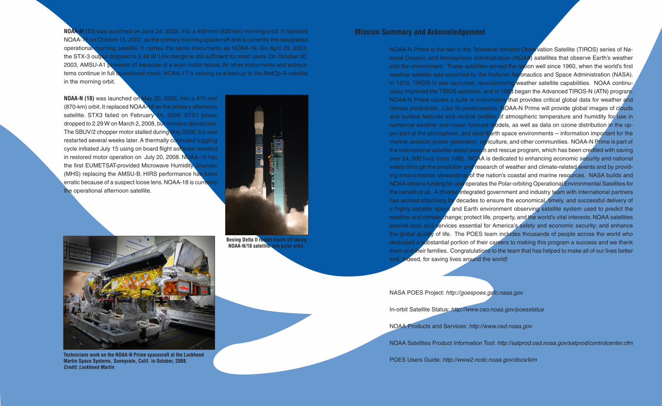
NOAA-M (17) was launched on June 24, 2002, into a 450-nmi (833 km) morning orbit. It replaced NOAA-15 on October 15, 2002, as the primary morning spacecraft and is currently the designated operational morning satellite. It carries the same instruments as NOAA-16. On April 28, 2003, the STX-3 output dropped to 2.48 W. Link margin is still sufficient for most users. On October 30, 2003, AMSU-A1 powered off because of a scan motor failure. All other instruments and subsys-tems continue in full operational mode. NOAA-17 is serving as a backup to the MetOp-A satellite in the morning orbit.
NOAA-N (18) was launched on May 20, 2005, into a 470-nmi (870-km) orbit. It replaced NOAA-16 as the primary afternoon satellite. STX3 failed on February 14, 2008. STX1 power dropped to 2.29 W on March 2, 2008, but remains operational. The SBUV/2 chopper motor stalled during May 2008, but was restarted several weeks later. A thermally controlled toggling cycle initiated July 15 using on board flight software resulted in restored motor operation on July 20, 2008. NOAA-18 has the first EUMETSAT-provided Microwave Humidity Sounder (MHS) replacing the AMSU-B. HIRS performance has been erratic because of a suspect loose lens. NOAA-18 is currently the operational afternoon satellite.
Mission Summary and Acknowledgement
NOAA-N Prime is the last in the Television Infrared Observation Satellite (TIROS) series of Na-tional Oceanic and Atmospheric Administration (NOAA) satellites that observe Earth’s weather and the environment. These satellites served the nation well since 1960, when the world’s first weather satellite was launched by the National Aeronautics and Space Administration (NASA). In 1978, TIROS-N was launched, revolutionizing weather satellite capabilities. NOAA continu-ously improved the TIROS satellites, and in 1983 began the Advanced TIROS-N (ATN) program. NOAA-N Prime carries a suite of instruments that provides critical global data for weather and climate predictions. Like its predecessors, NOAA-N Prime will provide global images of clouds and surface features and vertical profiles of atmospheric temperature and humidity for use in numerical weather and ocean forecast models, as well as data on ozone distribution in the up-per part of the atmosphere, and near-Earth space environments -- information important for the marine, aviation, power generation, agriculture, and other communities. NOAA-N Prime is part of the international satellite-aided search and rescue program, which has been credited with saving over 24, 500 lives since 1982. NOAA is dedicated to enhancing economic security and national safety through the prediction and research of weather and climate-related events and by provid-ing environmental stewardship of the nation’s coastal and marine resources. NASA builds and NOAA obtains funding for and operates the Polar-orbiting Operational Environmental Satellites for the benefit of all. A diverse integrated government and industry team with international partners has worked effectively for decades to ensure the economical, timely, and successful delivery of a highly capable space and Earth environment observing satellite system used to predict the weather and climate change; protect life, property, and the world’s vital interests. NOAA satellites provide data and services essential for America’s safety and economic security; and enhance the global quality of life. The POES team includes thousands of people across the world who dedicated a substantial portion of their careers to making this program a success and we thank them and their families. Congratulations to the team that has helped to make all of our lives better and, indeed, for saving lives around the world!
NASA POES Project: http://goespoes.gsfc.nasa.gov
In-orbit Satellite Status: http://www.oso.noaa.gov/poesstatus
NOAA Products and Services: http://www.osd.noaa.gov
NOAA Satellites Product Information Tool: http://satprod.osd.noaa.gov/satprod/controlcenter.cfm
POES Users Guide: http://www2.ncdc.noaa.gov/docs/klm
Beoing Delta II rocket blasts off taking NOAA-N/18 satellite into polar orbit.
Technicians work on the NOAA-N Prime spacecraft at the Lockheed Martin Space Systems, Sunnyvale, Calif. in October, 2008. Credit: Lockheed Martin
NOAA-N Prime/40 NOAA-N Prime/41
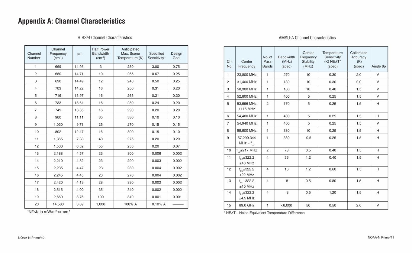
AMSU-A Channel Characteristics
Center Temperature Calibration No. of Bandwidth Frequency Sensitivity Accuracy Ch. Center Pass (MHz) Stability (K) NEΔT* (K) No. Frequency Bands (spec) (MHz) (spec) (spec) Angle 0p 1 23,800 MHz 1 270 10 0.30 2.0 V
2 31,400 MHz 1 180 10 0.30 2.0 V
3 50,300 MHz 1 180 10 0.40 1.5 V
4 52,800 MHz 1 400 5 0.25 1.5 V
5 53,596 MHz 2 170 5 0.25 1.5 H ±115 MHz
6 54,400 MHz 1 400 5 0.25 1.5 H
7 54,940 MHz 1 400 5 0.25 1.5 V
8 55,500 MHz 1 330 10 0.25 1.5 H
9 57,290.344 1 330 0.5 0.25 1.5 H MHz = fLO
10 fLO±217 MHz 2 78 0.5 0.40 1.5 H
11 fLO±322.2 4 36 1.2 0.40 1.5 H
±48 MHz
12 fLO±322.2 4 16 1.2 0.60 1.5 H
±22 MHz
13 fLO±322.2 4 8 0.5 0.80 1.5 H
±10 MHz
14 fLO±322.2 4 3 0.5 1.20 1.5 H
±4.5 MHz
15 89.0 GHz 1 <6,000 50 0.50 2.0 V
* NEΔT—Noise Equivalent Temperature Difference
Appendix A: Channel Characteristics
HIRS/4 Channel Characteristics
Channel Half Power Anticipated Channel Frequency μm Bandwidth Max. Scene Specified Design Number (cm-1) (cm-1) Temperature (K) Sensitivity 1 Goal
1 669 14.95 3 280 3.00 0.75
2 680 14.71 10 265 0.67 0.25
3 690 14.49 12 240 0.50 0.25
4 703 14.22 16 250 0.31 0.20
5 716 13.97 16 265 0.21 0.20
6 733 13.64 16 280 0.24 0.20
7 749 13.35 16 290 0.20 0.20
8 900 11.11 35 330 0.10 0.10
9 1,030 9.71 25 270 0.15 0.15
10 802 12.47 16 300 0.15 0.10
11 1,365 7.33 40 275 0.20 0.20
12 1,533 6.52 55 255 0.20 0.07
13 2,188 4.57 23 300 0.006 0.002
14 2,210 4.52 23 290 0.003 0.002
15 2,235 4.47 23 280 0.004 0.002
16 2,245 4.45 23 270 0.004 0.002
17 2,420 4.13 28 330 0.002 0.002
18 2,515 4.00 35 340 0.002 0.002
19 2,660 3.76 100 340 0.001 0.001
20 14,500 0.69 1,000 100% A 0.10% A ———
1NEΔN in mW/m2-sr-cm-1
NOAA-N Prime/42 NOAA-N Prime/43
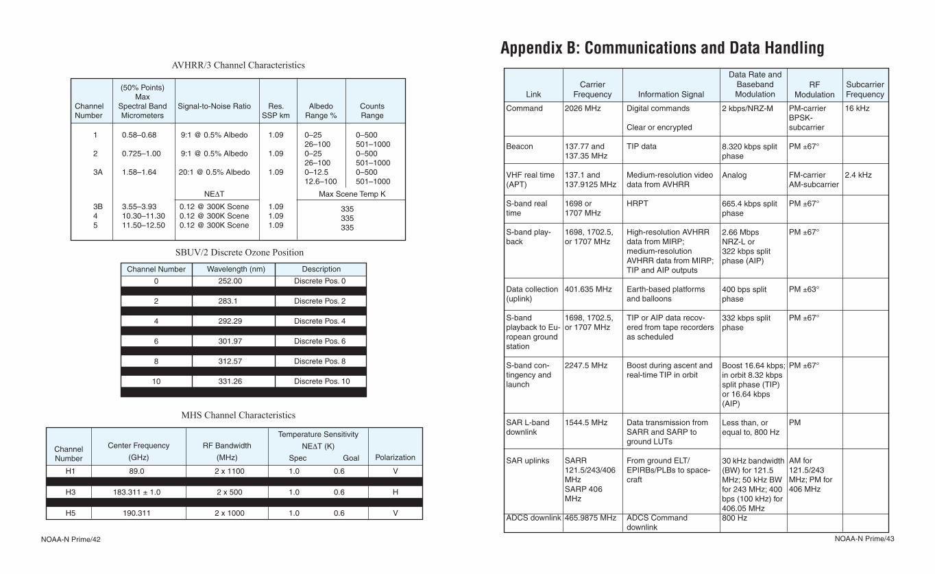
Appendix B: Communications and Data Handling
RF Modulation Link
Carrier Frequency Information Signal
Data Rate and Baseband Modulation
Subcarrier Frequency
Command
Beacon
VHF real time (APT)
S-band real time
S-band play-back
Data collection (uplink)
S-band playback to Eu-ropean ground station
S-band con-tingency and launch
SAR L-band downlink
SAR uplinks
ADCS downlink
2026 MHz
137.77 and 137.35 MHz
137.1 and 137.9125 MHz
1698 or 1707 MHz
1698, 1702.5, or 1707 MHz
401.635 MHz
1698, 1702.5, or 1707 MHz
2247.5 MHz
1544.5 MHz
SARR 121.5/243/406 MHzSARP 406 MHz
465.9875 MHz
Digital commands
Clear or encrypted
TIP data
Medium-resolution video data from AVHRR
HRPT
High-resolution AVHRR data from MIRP; medium-resolution AVHRR data from MIRP; TIP and AIP outputs
Earth-based platforms and balloons
TIP or AIP data recov-ered from tape recorders as scheduled
Boost during ascent and real-time TIP in orbit
Data transmission from SARR and SARP to ground LUTs
From ground ELT/EPIRBs/PLBs to space-craft
ADCS Command downlink
2 kbps/NRZ-M
8.320 kbps split phase
Analog
665.4 kbps split phase
2.66 Mbps NRZ-L or 322 kbps split phase (AIP)
400 bps split phase
332 kbps split phase
Boost 16.64 kbps; in orbit 8.32 kbps split phase (TIP) or 16.64 kbps (AIP)
Less than, or equal to, 800 Hz
30 kHz bandwidth (BW) for 121.5 MHz; 50 kHz BW for 243 MHz; 400 bps (100 kHz) for 406.05 MHz800 Hz
PM-carrier BPSK- subcarrier
PM ±67°
FM-carrierAM-subcarrier
PM ±67°
PM ±67°
PM ±63°
PM ±67°
PM ±67°
PM
AM for 121.5/243 MHz; PM for 406 MHz
16 kHz
2.4 kHz
MHS Channel Characteristics
AVHRR/3 Channel Characteristics
SBUV/2 Discrete Ozone Position
1 0.58–0.68 9:1 @ 0.5% Albedo 1.09 0–25 0–500 26–100 501–10002 0.725–1.00 9:1 @ 0.5% Albedo 1.09 0–25 0–500 26–100 501–10003A 1.58–1.64 20:1 @ 0.5% Albedo 1.09 0–12.5 0–500 12.6–100 501–1000
NEΔT Max Scene Temp K
3B 3.55–3.93 0.12 @ 300K Scene 1.09 4 10.30–11.30 0.12 @ 300K Scene 1.09 5 11.50–12.50 0.12 @ 300K Scene 1.09
(50% Points) MaxChannel Spectral Band Signal-to-Noise Ratio Res. Albedo CountsNumber Micrometers SSP km Range % Range
335335335
Wavelength (nm)
252.00 273.61 283.1 287.7 292.29 297.59 301.97 305.87 312.57 317.56 331.26 339.89
Description
Discrete Pos. 0Discrete Pos. 1Discrete Pos. 2Discrete Pos. 3Discrete Pos. 4Discrete Pos. 5Discrete Pos. 6Discrete Pos. 7Discrete Pos. 8Discrete Pos. 9Discrete Pos. 10Discrete Pos. 11
Channel Number
01234567891011
Channel Number
Center Frequency
(GHz)
H1H2H3H4H5
89.0157.0
183.311 ± 1.0183.311 ± 3.0
190.311
RF Bandwidth
(MHz)
Temperature Sensitivity
NEΔT (K)
Spec Goal Polarization
2 x 11002 x 11002 x 500
2 x 10002 x 1000
1.0 0.6 1.0 0.6 1.0 0.6 1.0 0.6 1.0 0.6
VVHHV
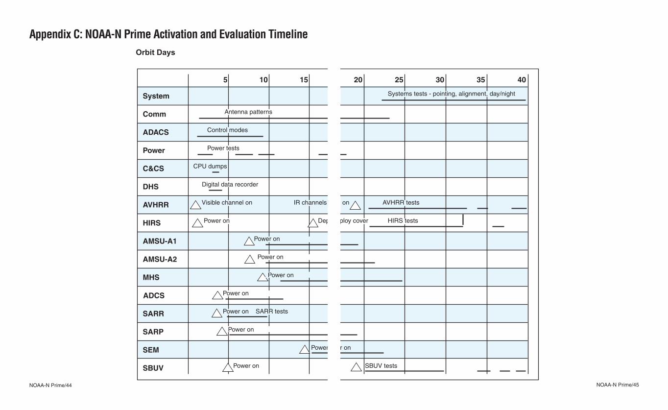
NOAA-N Prime/44 NOAA-N Prime/45
System
Comm
ADACS
Power
C&CS
DHS
AVHRR
HIRS
AMSU-A1
AMSU-A2
MHS
DCS
SARR
SARP
SEM
SBUV
10 20155 30 403525
Systems tests - pointing, alignment, day/night
Antenna patterns
Control modes
Power tests
CPU dumps
Digital data recorder
Visible channel on IR channels on AVHRR tests
Power on Deploy cover HIRS tests
Power on
Power on
Power on
Power on
Power on SARR tests
Power on
Power on
Power on SBUV tests
Appendix C: NOAA-N Prime Activation and Evaluation Timeline Orbit Days
System
Comm
ADACS
Power
C&CS
DHS
AVHRR
HIRS
AMSU-A1
AMSU-A2
MHS
DCS
SARR
SARP
SEM
SBUV
10 20155 30 403525
Systems tests - pointing, alignment, day/night
Antenna patterns
Control modes
Power tests
CPU dumps
Digital data recorder
Visible channel on IR channels on AVHRR tests
Power on Deploy cover HIRS tests
Power on
Power on
Power on
Power on
Power on SARR tests
Power on
Power on
Power on SBUV tests
ADCS
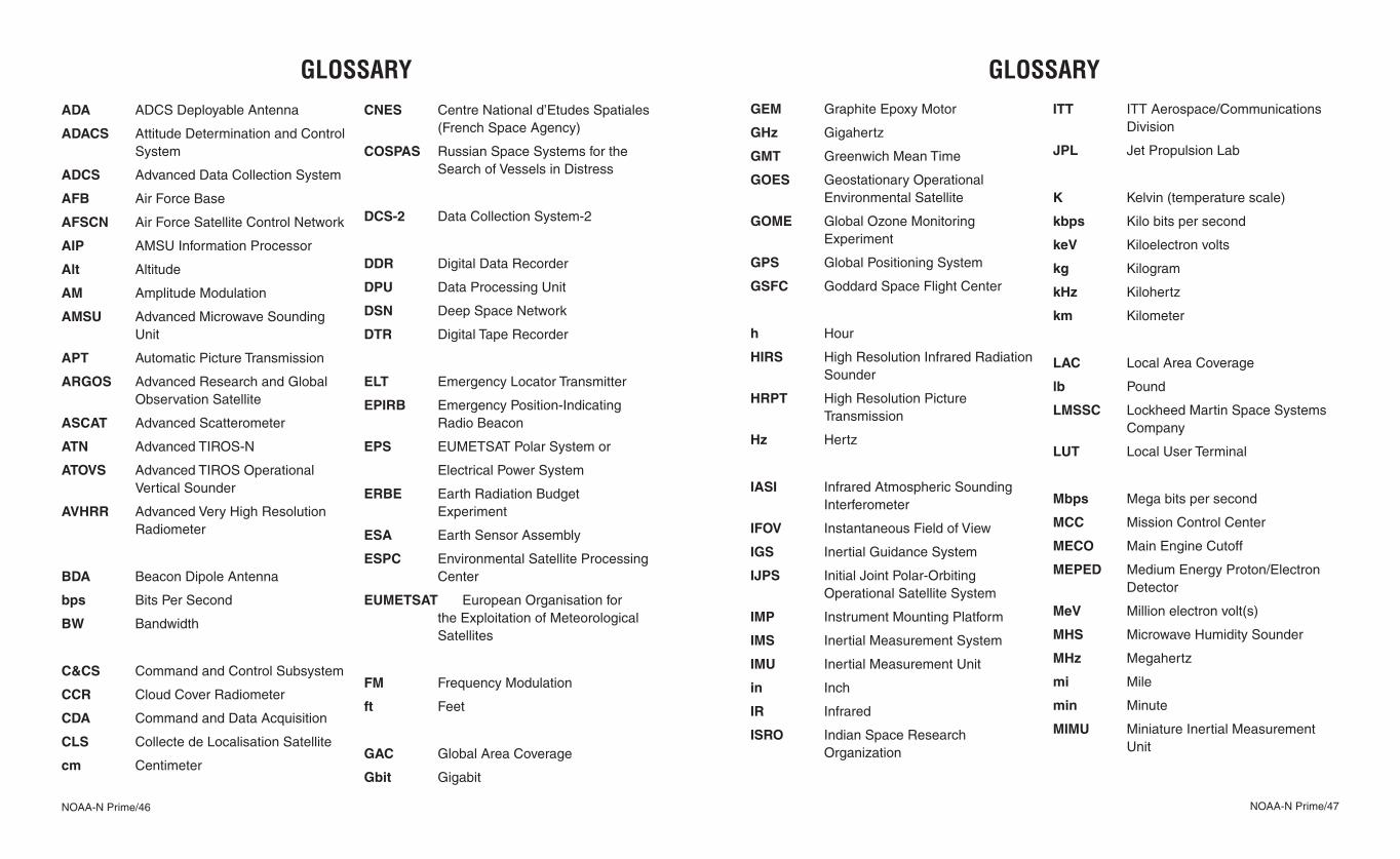
NOAA-N Prime/46 NOAA-N Prime/47
GLOSSARYGEM Graphite Epoxy Motor
GHz Gigahertz
GMT Greenwich Mean Time
GOES Geostationary Operational Environmental Satellite
GOME Global Ozone Monitoring Experiment
GPS Global Positioning System
GSFC Goddard Space Flight Center
h Hour
HIRS High Resolution Infrared Radiation Sounder
HRPT High Resolution Picture Transmission
Hz Hertz
IASI Infrared Atmospheric Sounding Interferometer
IFOV Instantaneous Field of View
IGS Inertial Guidance System
IJPS Initial Joint Polar-Orbiting Operational Satellite System
IMP Instrument Mounting Platform
IMS Inertial Measurement System
IMU Inertial Measurement Unit
in Inch
IR Infrared
ISRO Indian Space Research Organization
ITT ITT Aerospace/Communications Division
JPL Jet Propulsion Lab
K Kelvin (temperature scale)
kbps Kilo bits per second
keV Kiloelectron volts
kg Kilogram
kHz Kilohertz
km Kilometer
LAC Local Area Coverage
lb Pound
LMSSC Lockheed Martin Space Systems Company
LUT Local User Terminal
Mbps Mega bits per second
MCC Mission Control Center
MECO Main Engine Cutoff
MEPED Medium Energy Proton/Electron Detector
MeV Million electron volt(s)
MHS Microwave Humidity Sounder
MHz Megahertz
mi Mile
min Minute
MIMU Miniature Inertial Measurement Unit
GLOSSARYADA ADCS Deployable Antenna
ADACS Attitude Determination and Control System
ADCS Advanced Data Collection System
AFB Air Force Base
AFSCN Air Force Satellite Control Network
AIP AMSU Information Processor
Alt Altitude
AM Amplitude Modulation
AMSU Advanced Microwave Sounding Unit
APT Automatic Picture Transmission
ARGOS Advanced Research and Global Observation Satellite
ASCAT Advanced Scatterometer
ATN Advanced TIROS-N
ATOVS Advanced TIROS Operational Vertical Sounder
AVHRR Advanced Very High Resolution Radiometer
BDA Beacon Dipole Antenna
bps Bits Per Second
BW Bandwidth
C&CS Command and Control Subsystem
CCR Cloud Cover Radiometer
CDA Command and Data Acquisition
CLS Collecte de Localisation Satellite
cm Centimeter
CNES Centre National d’Etudes Spatiales (French Space Agency)
COSPAS Russian Space Systems for the Search of Vessels in Distress
DCS-2 Data Collection System-2
DDR Digital Data Recorder
DPU Data Processing Unit
DSN Deep Space Network
DTR Digital Tape Recorder
ELT Emergency Locator Transmitter
EPIRB Emergency Position-Indicating Radio Beacon
EPS EUMETSAT Polar System or
Electrical Power System
ERBE Earth Radiation Budget Experiment
ESA Earth Sensor Assembly
ESPC Environmental Satellite Processing Center
EUMETSAT European Organisation for the Exploitation of Meteorological Satellites
FM Frequency Modulation
ft Feet
GAC Global Area Coverage
Gbit Gigabit
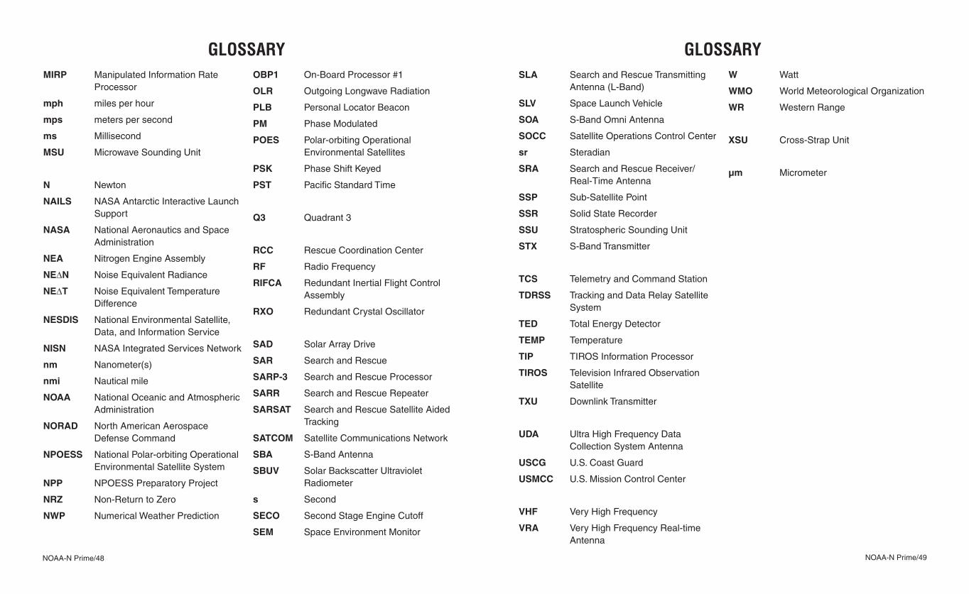
NOAA-N Prime/48 NOAA-N Prime/49
SLA Search and Rescue Transmitting Antenna (L-Band)
SLV Space Launch Vehicle
SOA S-Band Omni Antenna
SOCC Satellite Operations Control Center
sr Steradian
SRA Search and Rescue Receiver/Real-Time Antenna
SSP Sub-Satellite Point
SSR Solid State Recorder
SSU Stratospheric Sounding Unit
STX S-Band Transmitter
TCS Telemetry and Command Station
TDRSS Tracking and Data Relay Satellite System
TED Total Energy Detector
TEMP Temperature
TIP TIROS Information Processor
TIROS Television Infrared Observation Satellite
TXU Downlink Transmitter
UDA Ultra High Frequency Data Collection System Antenna
USCG U.S. Coast Guard
USMCC U.S. Mission Control Center
VHF Very High Frequency
VRA Very High Frequency Real-time Antenna
W Watt
WMO World Meteorological Organization
WR Western Range
XSU Cross-Strap Unit
μm Micrometer
GLOSSARYMIRP Manipulated Information Rate
Processor
mph miles per hour
mps meters per second
ms Millisecond
MSU Microwave Sounding Unit
N Newton
NAILS NASA Antarctic Interactive Launch Support
NASA National Aeronautics and Space Administration
NEA Nitrogen Engine Assembly
NE∆N Noise Equivalent Radiance
NE∆T Noise Equivalent Temperature Difference
NESDIS National Environmental Satellite, Data, and Information Service
NISN NASA Integrated Services Network
nm Nanometer(s)
nmi Nautical mile
NOAA National Oceanic and Atmospheric Administration
NORAD North American Aerospace Defense Command
NPOESS National Polar-orbiting Operational Environmental Satellite System
NPP NPOESS Preparatory Project
NRZ Non-Return to Zero
NWP Numerical Weather Prediction
OBP1 On-Board Processor #1
OLR Outgoing Longwave Radiation
PLB Personal Locator Beacon
PM Phase Modulated
POES Polar-orbiting Operational Environmental Satellites
PSK Phase Shift Keyed
PST Pacific Standard Time
Q3 Quadrant 3
RCC Rescue Coordination Center
RF Radio Frequency
RIFCA Redundant Inertial Flight Control Assembly
RXO Redundant Crystal Oscillator
SAD Solar Array Drive
SAR Search and Rescue
SARP-3 Search and Rescue Processor
SARR Search and Rescue Repeater
SARSAT Search and Rescue Satellite Aided Tracking
SATCOM Satellite Communications Network
SBA S-Band Antenna
SBUV Solar Backscatter Ultraviolet Radiometer
s Second
SECO Second Stage Engine Cutoff
SEM Space Environment Monitor
GLOSSARY