No lathe? – No Problem!No lathe? – No Problem! J. D. Michne I was in the Northeastern...
17
No lathe? – No Problem! J. D. Michne I was in the Northeastern Woodworkers Association (NWA) Learning Center, teaching some members how to build a cedar stripped canoe. There were some other members working on banjoes in Ken’s class there. That looked like a neat woodworking project, so I told Ken if he ever did another class, sign me up. He did, and since I was between building boats, I became a novice luthier. I don’t need a banjo and can’t play one (yet), but the craftsmanship challenge would be exciting. Ken’s method of building the rim consists of accurately cutting six identical blocks with 30⁰ angles on the ends, and gluing them together into a perfect hexagon. Make three or four assemblies, and then glue the whole stack together. Then we rough-cut the outside round to just a bit oversize on a band saw. One of the students brought in a long-bladed jig saw, and roughed out the inside to near round. The whole thing was then mounted on a backer board and faceplate and turned round on a lathe. Another lathe session two weeks later brought the piece to perfectly round at the correct final dimensions.
Transcript of No lathe? – No Problem!No lathe? – No Problem! J. D. Michne I was in the Northeastern...

No lathe? – No Problem! J. D. Michne
I was in the Northeastern Woodworkers Association (NWA) Learning Center, teaching some members how to build a cedar stripped canoe. There were some other members working on banjoes in Ken’s class there. That looked like a neat woodworking project, so I told Ken if he ever did another class, sign me up. He did, and since I was between building boats, I became a novice luthier. I don’t need a banjo and can’t play one (yet), but the craftsmanship challenge would be exciting.
Ken’s method of building the rim consists of accurately cutting six identical blocks with 30⁰ angles on the ends, and gluing them together into a perfect hexagon. Make three or four assemblies, and then glue the whole stack together.
Then we rough-cut the outside round to just a bit oversize on a band saw. One of the students brought in a long-bladed jig saw, and roughed out the inside to near round. The whole thing was then mounted on a backer board and faceplate and turned round on a lathe. Another lathe session two weeks later brought the piece to perfectly round at the correct final dimensions.

Ken’s classes are every other Friday afternoon, so there was a lot of time between sessions. When I have a lot of extra time, I think. When I think, I can be dangerous…
What if one of the joints in the hexagon was not glued, then sprung open enough to slip the band saw blade though it? Cutting the inside of the individual rings would be easy. For that matter, if the rings were cut accurately enough to require just sanding to final dimension after gluing, the need for a lathe would be eliminated. Furthermore, the width of the blocks required to get a circle out of a polygon would be reduced if there were eight blocks instead of six. Off to the computer and CAD. I drew two concentric circles 3/4" apart, and then surrounded them with an octagon inside and out.
The dimensions of the segments are 11/2" wide, 43/4" on the long side, and a complementary angle of 221/2⁰ between the long side and the cut ends. The ring is 11" outside diameter, 3/4" thick1. With the dimensions now defined, I could use a sled to cut the identical segments on the table saw.
I had a sled set up to cut the 30⁰ angles for my class banjo, so changing the angle to exactly
221/2⁰ was next. How was I to get that angle, and as close to exact as possible? Without some sort of reference device, it would have to be by trial and error, commonly called “sneaking up on
1 In Ken’s class, resonator banjo rims are 3/4" thick; open backs are 1/2".
it”. I made sure the miter gage on the table saw was exactly square to the blade (the plate, not the teeth), and the pointer on the head was set exactly to 0⁰. Then I rotated the miter gage head
so the pointer was as close to 671/2⁰ as I could estimate, and locked it. I cut that angle on a piece of 1/4" plywood, and used it as a preliminary reference to set up the sled. I cut the reference piece the same width as the desired blocks, and around a foot long.
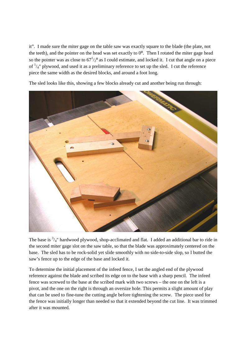
The sled looks like this, showing a few blocks already cut and another being run through:
The base is 3/4" hardwood plywood, shop-acclimated and flat. I added an additional bar to ride in the second miter gage slot on the saw table, so that the blade was approximately centered on the base. The sled has to be rock-solid yet slide smoothly with no side-to-side slop, so I butted the saw’s fence up to the edge of the base and locked it.
To determine the initial placement of the infeed fence, I set the angled end of the plywood reference against the blade and scribed its edge on to the base with a sharp pencil. The infeed fence was screwed to the base at the scribed mark with two screws – the one on the left is a pivot, and the one on the right is through an oversize hole. This permits a slight amount of play that can be used to fine-tune the cutting angle before tightening the screw. The piece used for the fence was initially longer than needed so that it extended beyond the cut line. It was trimmed after it was mounted.

The outfeed stop block is simply a convenient piece of scrap wood screwed down as a stop. Its position defines the length of the cut segment, which can be determined using the plywood angle reference. Simply make a mark on the reference at the proper dimension (43/4" on the long side) and align the mark at the tip of the outside of a saw tooth as if it would be cut, and screw the block down. Both screw holes are over-size, again to permit minor adjustments.
This is a good place to mention some nitty gritty details easily overlooked. Ignoring them can result in problems as you go along. Remember, using a lathe produces the perfect round. We want to be able to come as close as possible to perfectly round without a lathe. Achieving this requires your tools to be set up as precisely as possible.
First, the table saw must be accurately aligned – fence parallel to the blade, blade parallel to the miter gage slot and square to the table. A good sharp blade capable of making smooth cuts is essential. I prefer the 71/4" Freud Diablo D0760R, 60 teeth, with a 1/16" kerf. The band saw table must be square to the blade, and likewise for any sander you may use. The jointer tables must be aligned and the fence square to the tables. Test cuts in scrap will show the need for any adjustments.
The sled now has to be set up to make perfect cuts. This may take a while, but if you were lucky making the reference piece it should go well. Using scrap wood, make some pieces 11/2" wide and a couple of feet long. They should be 3/4" thick, but need not be precise. We only want to verify the cutting angle – 1-by pine will do.
Make an angle cut on one end of a test piece. Insure there are no chips or sawdust anywhere on the sled where the stock will be placed. A chip brush works well here. Positioning the stock for the next cut with even a small chip under it can cause a skewed cut. Rotate and position the test piece on the sled with the cut end against the stop block, and cut a block. Any time you are about to make a cut, make sure the cut end is firmly against the stop block, and the stock is held tightly against the infeed fence. The goal here is reproducible precision in the cut blocks. Make eight blocks.
Dry-assemble the blocks into an octagon on a flat surface and clamp them as if they were a glue-up assembly. The Merle clamp works well in Ken’s class, but at home, I use a band clamp with shop-made shaped clamping cauls at the joints. (See the picture on the next page.) Examine the clamped assembly closely. There should be no gaps anywhere and the corners should all align. Press each piece to the table to ensure all surfaces of the assembly are in the same plane. If there are any gaps, the cutting angle of the fence needs adjustment. Loosen the screw closest to the blade, and very slightly pivot the fence just a hair one way or the other depending on where the gaps in the assembly are. This adjustment should be just barely perceptible. Then try again. Don’t try to trim the ends of each block – this is a safety issue.
If all is well, you could start on the real thing, but don’t do it yet. Use full-size test pieces to assemble an octagon before committing to the real wood. Apply glue liberally to each joint except for the last one. Leave this joint dry, and clamp the assembly together. The dry joint will be tight when the glue cures and the clamp is released. This joint will become the gateway for

the band saw blade for sawing the inside round. Don’t try to spring the joint open just yet. Forcing it open could cause a failure in one of the glued joints. Simply mark the joint for now. Let the glue dry for about 30 minutes, and remove most of the squeezed out glue with a putty knife. This makes it easier for drum sanding later. The heat of sanding softens the glue, which then gums up the sand paper.
With the cutting angle set and a successful test glue-up, the next step is to make wood for the real thing. That is, joint one surface of the raw stock, then joint one edge square to the jointed face, thickness plane the raw surface to bring it parallel to the jointed face, and finally rip it to final width with the jointed square edge against the saw fence. This is a very important sequence. In order to get perfect glue joints on a flat and uniformly thick assembly, the component parts must be straight, flat, square, true, level, plumb, dry, etc., - “close enough” not allowed.
Glued octagon – Note the one dry joint.
How many assemblies are needed to make a banjo? If the wood is nominally 3/4" thick, four rings in a stack will yield a pot about 3" high. The top ring will be either shaped for a metal tone ring or chamfered for using the top ring as the tone ring. The bottom ring can always be thinned to the final desired height after assembly. For purposes of this discussion, I will assume four rings.
Scrape the dried glue off as much as possible without being surgical about it. It is better to leave a little bit rather than scraping a divot into the wood.

Drum-sand both sides of the assemblies. Examine the sanded surfaces closely, and repeat until the entire surface has the same texture and there are no glue remnants. You are now ready to make round rings.
The reference for turning a ring on the lathe is the axis of the lathe, which extends through the stock being turned. Whatever is turned about the axis can be brought perfectly round by the application of various tools. What is the reference for making a ring from wood without a lathe? The center of the circle is not defined, since it does not exist in a real object. The solution is to attach a temporary and reproducible reference center.
Note in the drawing on page 2 that there are two centerlines crossing at right angles. These lines also intersect joints in the octagon. For any opposing pair of joints, there are equivalent pairs of joints at exact right angles to it. Here is the solution to the reference center problem. By attaching a plywood disk cut in a perfect circle to the octagon, the center of the disk becomes the center of the octagon.
To make the reference disk, rip a piece of 1/4" plywood about a half inch wider than the desired outside diameter of the final ring. Without changing the table saw fence, turn the ripped piece 90⁰ and cut it again, producing a perfect square. Then very carefully draw diagonal lines across the entire piece of plywood from corner to corner. Take extreme care in doing this, use a fine point pencil, and make sure the lines do indeed intersect the corners as near perfect as possible. The center of the square is where the lines cross.2
With a center point now defined, the disk must be cut out from the square. An easy way to cut it is with a band saw fitted with a circle-cutting jig. There is any number of such jigs around in woodworking publications; I prefer the easily adjustable version from ShopNotes magazine.3 Drill a small hole at the center of the square to fit the pivot pin of your jig, and cut out the circle. Extend each of the centerlines across the edge of the disk, and whittle a bevel about an inch long and a sixteenth wide somewhere on the edge opposite the side with the lines on it. Its purpose will be described later.
Next is to align the circle so that its center is at the center of the octagon. Attach four pieces of approximately equally spaced double stick tape to the test octagon, and lay thin spacers of plastic or wood between the tape pieces. Lay the disk on to the test octagon, and align all four centerline marks exactly over four joints in the octagon. The easiest way is to first align two vertical marks, then move the disk up or down to align the horizontal marks. When all four marks are aligned with joints, press down on the center of the disk so that it does not move and remove the spacers. Apply pressure all around the disk to ensure it is firmly held by the tape.
2 Aren’t you glad you took geometry in school? 3 ShopNotes.com, back Issue No. 15

With the jig in cutting position on the band saw table, adjust the position of the pivot to make the cut about 1/16" larger than the final radius of the ring. The extra width is for disk sanding the final assembly of four stacked and glued rings. Cut the ring from the test octagon, and examine the result. If all is well, make and cut the real thing. If the diameter of the cut-out is not as desired, make a correction to the pivot placement before cutting the real thing.
That little bevel you whittled on the edge of the reference disk now comes in handy. Insert a thin wedge into the bevel and slowly push it in under the disk. This gently separates the disk with little or no damage to the tape, allowing possible re-use.
Now you are ready to cut the inside.
The cut can be made freehand after making a reference disk to mark the inside cut line, or cut with greater precision using a simple jig shown below. Two pegs in the jig are used as guides for rotating the ring as the inside is cut; the other two are for cutting the inside of a resonator ring.

Start with a flat piece of 3/4" plywood, 12" x 18". On the band saw, measure the distance from the blade to the miter gage slot. Add 21/2" to the measurement and install a runner that distance from the left edge of the board that will fit the slot. Place the board on the saw table with the runner in the slot, and cut a kerf about 21/2" long. Turn off the saw, but don’t move the board. Mark the location of the edge of the table on the underside of the board, remove it, and install a stop block at the mark.
The end of the kerf is the reference for laying out the position of the guide pegs. The pegs are 1/2" dowels 11/2" long, driven tight or glued into the board. The leftmost peg interferes with cutting a resonator ring, and therefore must be removable4.
To locate the pegs, it can be done by measurements or by using the test ring for the layout. The pegs at the top of the board in the above picture determine the diameter of the inside of the cuts; the two lower pegs keep the rings and blade aligned during the cuts (rim rings and resonator).
For a banjo rim 11" OD and 3/4" wide, the peg on the right in the above picture should be centered at 101/2" from the blade on a line beginning at the end of and square to the kerf. This, of course, is theoretical and assumes the outside has been cut and sanded to final dimension. Don’t do it. Any allowance for later sanding the completed rim round to final dimensions must be accounted for before placing the pegs. An easier way is to cut the inside of the test ring without the jig, and use that to determine final peg positions. The bottom pegs are located half the distance from the blade to the right pegs, and half the outside diameter of the rings below the blade/peg line.
Start by making a plywood reference disk the desired diameter of the inside, center it on the test ring as previously described, and trace it onto the work piece. To cut the inside, position the outside of the ring behind the blade without the jig, with the dry joint facing the back of the blade. Carefully pull the joint open just enough to allow the joint to be passed over the blade. 4 The removable peg should be a tight fit, requiring a mallet to drive it in or out.

Cut the inside of the test ring just outside the marked line, leaving an allowance for sanding. Remove it, again moving the ring from behind the blade. Now one would think that was easy – why bother with the jig? The jig permits much more precise and reproducible cuts, which means better alignment when the four rings are glued in a stack, and best of all, less sanding later of the glued up stack. It also contributes to an intangible component part – craftsmanship.
Starting the inside cut using the jig is nigh impossible, what with the pegs in the way. The solution is to start without the jig. The goal is to get the blade into the cutting position while the ring is against both pegs. Measure the distance from the blade to the top left peg. Make a mark on the work piece at this distance from the outside of the ring to the dry joint. Make a cut from about the middle of a segment, curving into the mark. Since the cut ends at the dry joint, a chip should fall away leaving the blade ready to cut the inside.
The clearance starting cut at the dry joint

With the clearance cut made, install the jig firmly against the table stop block. It is a good idea to clamp it to the saw table. Place the ring against the blade at the start position, and against the two guide pegs. Turn on the saw, and rotate the ring while firmly holding it against the pegs.
Cutting the inside of a ring
With the rings cut, spring the dry joints apart slightly and work some glue into the opening. Clamp them with web clamps (no cauls required) for an hour or so, remove the clamps, and clean up any glue squeeze out.

Next is to glue up the stack.
There are two considerations in gluing the stack together. First, how to prevent the slippery wet glued pieces from getting out of alignment when applying the clamps, and aligning the rings while building the stack.
Drive three 1/2" brads approximately equally spaced about half way into the tops of three rings, and clip off the tops. This leaves a sharp tit that will anchor the ring placed on top of it and prevent slipping in wet glue. The top ring should not have any brads.
Half-inch brad, and one clipped
Next is to assure the alignment of each ring with the previous one while gluing the stack together. Proper alignment is essential, since removing wood on the outside due to a shifted ring on the completed glue-up requires the same amount of wood to be removed on the inside. The net result is a thinner pot than desired. I cobbled together an L shaped arrangement that will hold the rings properly aligned during assembly. It looks like this:

I started with a piece of plywood on my table saw table to protect the cast iron from glue drips. Then I laid down some sheet plastic as further protection. A tall temporary fence was clamped to the saw’s fence, and an L-shaped fence clamped to the saw fence to form a solid corner. Any ring placed in the corner will align with a previous ring, providing all rings are identically sized and touch the sides of the corner. Then I cut a pair of 2 x 2 supports that will raise the stack allowing clamps to be easily placed.
To do the glue-up, the bottom ring with the cut off brads facing up was placed as shown in the above picture, and glue5 applied. The next ring was carefully placed, holding the ring above the bottom ring while keeping it held against the corner. It was then lowered to the bottom ring, and pressed down so that the brad tips grabbed. The rest of the rings were added to the stack in like fashion.
Next was placing the clamps. I used 4-inch C-clamps, placing two or three to initially clamp the structure while still in the corner. The stack was now stable, so I removed the corner planks and placed more clamps. The stack now looks like this:
A scrap pine test pot
5 Original Titebond recommended

Let the glue dry for an hour or so, carefully remove the clamps, and scrape off as much partially dried glue as possible, inside and out. Set the assembly aside over night to let the glue cure completely.
Sanding the stack is another exercise in rotating it against a sanding medium in a manner that maintains it round. I found that for the outside, rotating it against a disk sander was not only simple, but also very effective. The disk sander should be loaded with a coarse grit. Since I use mine virtually always for shaping, I use 60-grit. The stack can be finished manually later to finer grits with a random orbit or finishing sander.
The disk sander has to be set up with a pivot point, which is adjustable for the distance from it to the disk. I have a moveable pin that came with the machine for sanding circles, which is functional, if not elegant. I fashioned a couple of adjustable stop blocks, one for rims and one for resonator rings, that prevent any further adjustment less than the desired outside radius of the pot. A screw in the end of the block can be turned in our out to tweak the sanding diameter.
In operation, the reference disk is retaped to the stack, and placed on the pivot pin. The pivot pin block is loose in the grove, but halted automatically by the stop block when the desired diameter is reached.
Sanding generates heat. Heat softens glue. Softened glue plugs up the sander, which in the extreme, can reduce the effectiveness of the operation to zero. By taking light cuts and cleaning the disk with a crepe rubber sanding eraser each time an adjustment is made, the sanding will be efficient, effective, and actually pleasant.
Adjustable pivot and stops A finished pot
Cleaning up the inside was done with an oscillating spindle sander, with no particular attention paid to making it precisely round since there is nothing of great importance on the inside requiring it. I used a 2" coarse grit spindle. Sanding motion was such that roundness was very nearly approximated due to the random nature of the strokes. I swung the inside of the pot into the spindle from left to right, beginning the stroke against the direction of rotation of the spindle, and then changed to right to left, all the while keeping contact. I fed it rather rapidly so as not to end up with a divot. Imagine if you were sanding by hand, with a back and forth stroke at a
medium speed. At the end of the stroke, I moved the pot away from the spindle, rotated it clockwise about as much as the length of the stroke, and continued the sequence until the sanding was complete.
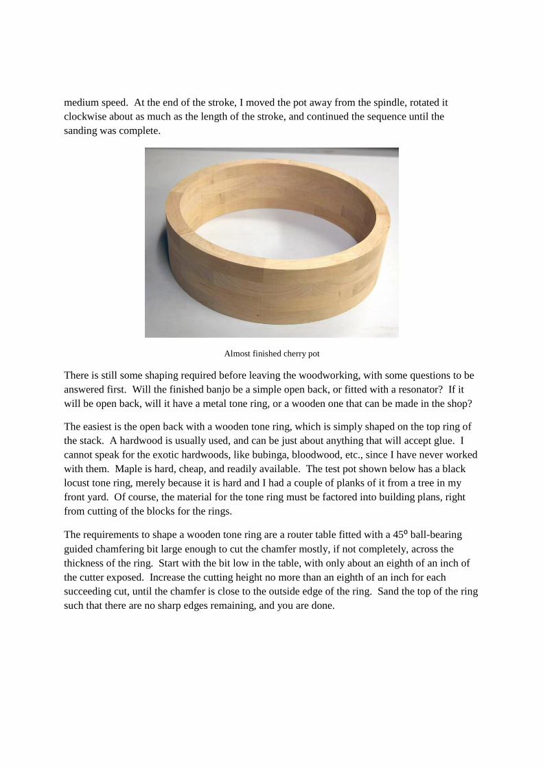
Almost finished cherry pot
There is still some shaping required before leaving the woodworking, with some questions to be answered first. Will the finished banjo be a simple open back, or fitted with a resonator? If it will be open back, will it have a metal tone ring, or a wooden one that can be made in the shop?
The easiest is the open back with a wooden tone ring, which is simply shaped on the top ring of the stack. A hardwood is usually used, and can be just about anything that will accept glue. I cannot speak for the exotic hardwoods, like bubinga, bloodwood, etc., since I have never worked with them. Maple is hard, cheap, and readily available. The test pot shown below has a black locust tone ring, merely because it is hard and I had a couple of planks of it from a tree in my front yard. Of course, the material for the tone ring must be factored into building plans, right from cutting of the blocks for the rings.
The requirements to shape a wooden tone ring are a router table fitted with a 45⁰ ball-bearing guided chamfering bit large enough to cut the chamfer mostly, if not completely, across the thickness of the ring. Start with the bit low in the table, with only about an eighth of an inch of the cutter exposed. Increase the cutting height no more than an eighth of an inch for each succeeding cut, until the chamfer is close to the outside edge of the ring. Sand the top of the ring such that there are no sharp edges remaining, and you are done.

Chamfered wood tone ring on a test rim. I tried to cut a resonator flange rabbet by rotating the rim across the end of a router bit, without much success. Later attempts at cutting with the side of a router bit on other rims were
much better
If a metal tone ring, such as the Five Star bluegrass flathead and arch tops described in the Stewart-MacDonald catalog is used, a rabbet must be cut in the rim to accept either. These items may have a lot of dimensional variability; therefore, it is highly recommended that the actual tone ring, and resonator flange if used, be available before starting the cutting.
A precision router table must be used, preferably one with a router lift capable of making minute adjustments in bit height. A good sharp 1/2" bit with a cutter length of at least an inch and a half is also required. An L-shaped fence should be clamped to the router table fence on the left side at a distance of one-half the diameter of the rim and against the bit rotation.

The fence should be initially positioned so that only about a thirty-second of an inch of the cutter edge is exposed, and the bit height is at about an eighth of an inch. With the router running, position the rim to the right of the bit and slide it into the cutter until it is firmly positioned against both fences. Rotate the rim counter clockwise one full revolution, keeping it against both fences. Examine the cut for consistent depth, and run it through again without changing bit position if there are any thin spots.
Try the fit of the tone ring. At this point, it should not yet fit. If it does just fit, the depth of the rabbit is correct. If not, the fence has to be moved back just a tiny amount and another pass made. Most table fences have a clamp at each end, which gives us a way to move the fence a few mils at a time. I marked the position of the fence near the right end clamp by making a pencil mark on the table against the fence. Then I loosened the clamp and softly nudged the end of the fence away from the bit a just perceptible amount, like a few mils, and made another pass. I kept repeating this sequence until the tone ring just fit the rabbet, which now sets the final cutting depth. Ken calls this “sneaking up on it”.
With the cutting depth of the rabbet now established, raise the bit about an eighth of an inch, and make another pass. Repeat the sequence until there is less than an eighth of an inch to go until the tone ring just rests on the top of the pot and the shoulder of the rabbet. Sneak up on it with small incremental raises of the bit until the ring rests equally on the rabbet shoulder and the top of the inside of the rim.

The whole process is then repeated to fit a resonator flange.
Done.
Finished pot. The rest is lutherie.