nMotion Mach3 USB Motion Card Installation Manual · nMotion Mach3 USB Motion Card Installation...
28
nMotion Mach3 USB Motion Card Installation Manual Features: Fully supporting all Mach3 versions, including the Mach3 R3.043.066 version. Supporting Windows series, including Windows2000/XP/Vista/Win7/Win8/Win10. No need to install any USB drivers,it can be used aftr plugging in the computer. USB bus is the use of magnetic coupling isolation, isolation of real value, different from the general control card optocoupler input and output, do high reliability, absolute guarantee the safety of the computer USB. At the same time to ensure that the strong anti-interference ability of EMC. The single chip, the system stability is more streamlined, multi chip processing generally incomparable Dual core ultra - high speed CPU (the maximum single core frequency 204MHz), operation processing ability has great redundancy, and ensure the realization of four axis linkage under 500KHz frequency of the pulse output, 6 axis pulse output frequencies up to 300kHz, connected to the servo / step Motion control buffer size can be set and ensure the fast interpolation cycle can stable operation, computer running overload can also smooth operation and interpolation cycle adjustable, can adapt to a variety of different needs. Has 16 input port, input interface more simple, port of wet and dry contact can be, wiring is simple, dry contact method for as long as the external connected to a physical switch to the wire can be, all 16 input port are indication signal, for low power usually indicating lamp is bright, debugging simple and clear. With 8 output ports, a single output drive capability of 500mA, can be directly driven by DC relay. The PWM speed output port can be set, the frequency of PWM, pulse width 0~1000 continuously adjustable. With the function of the speed, the actual speed of the spindle in the Mach3 interface, real-time display, accurate and stable measurement. With 256 bytes of NVRAM space, can save the coordinates of the 6 axes, the next power without the need to find the mechanical origin. The circuit board is made by the engineer, the design level is clear at a glance.
Transcript of nMotion Mach3 USB Motion Card Installation Manual · nMotion Mach3 USB Motion Card Installation...
nMotion Mach3 USB Motion Card Installation Manual
Features:
Fully supporting all Mach3 versions, including the Mach3 R3.043.066 version.
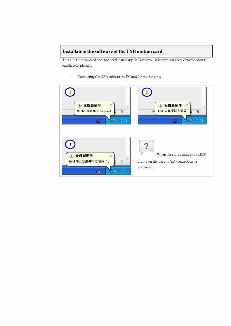
Supporting Windows series, including Windows2000/XP/Vista/Win7/Win8/Win10.
No need to install any USB drivers,it can be used aftr plugging in the computer.
USB bus is the use of magnetic coupling isolation, isolation of real value, different from the general control
card optocoupler input and output, do high reliability, absolute guarantee the safety of the computer USB. At
the same time to ensure that the strong anti-interference ability of EMC.
The single chip, the system stability is more streamlined, multi chip processing generally incomparable
Dual core ultra - high speed CPU (the maximum single core frequency 204MHz), operation processing ability
has great redundancy, and ensure the realization of four axis linkage under 500KHz frequency of the pulse
output, 6 axis pulse output frequencies up to 300kHz, connected to the servo / step
Motion control buffer size can be set and ensure the fast interpolation cycle can stable
operation, computer running overload can also smooth operation and interpolation cycle
adjustable, can adapt to a variety of different needs.
Has 16 input port, input interface more simple, port of wet and dry contact can be, wiring is
simple, dry contact method for as long as the external connected to a physical switch to the
wire can be, all 16 input port are indication signal, for low power usually indicating lamp is
bright, debugging simple and clear.
With 8 output ports, a single output drive capability of 500mA, can be directly driven by DC
relay.
The PWM speed output port can be set, the frequency of PWM, pulse width 0~1000
continuously adjustable.
With the function of the speed, the actual speed of the spindle in the Mach3 interface,
real-time display, accurate and stable measurement.
With 256 bytes of NVRAM space, can save the coordinates of the 6 axes, the next power
without the need to find the mechanical origin.
The circuit board is made by the engineer, the design level is clear at a glance.
Revisions List
Basic connection diagram (an Overview) .......................................................................... 3
Mechanical dimensions diagram ....................................................................................... 5
Prepare Mach3 software ................................................................................................... 6
A. Installing the motion card plug‐in. ................................................................................ 9
B. Setup for Mach3 ...................................................................................................... 10
Hardware installation of motion control card ................................................................. 13
8 way control output pin position diagram ..................................................................... 14
External power knob ....................................................................................................... 15
Spindle speed PWM analog output................................................................................. 17
Probe connection ............................................................................................................ 21
MPG Setting .................................................................................................................... 23
Software configuration .................................................................................................... 24
MPG soft mode: .............................................................................................................. 25
MPG hard mode .............................................................................................................. 26
Using NVRAM .................................................................................................................. 28
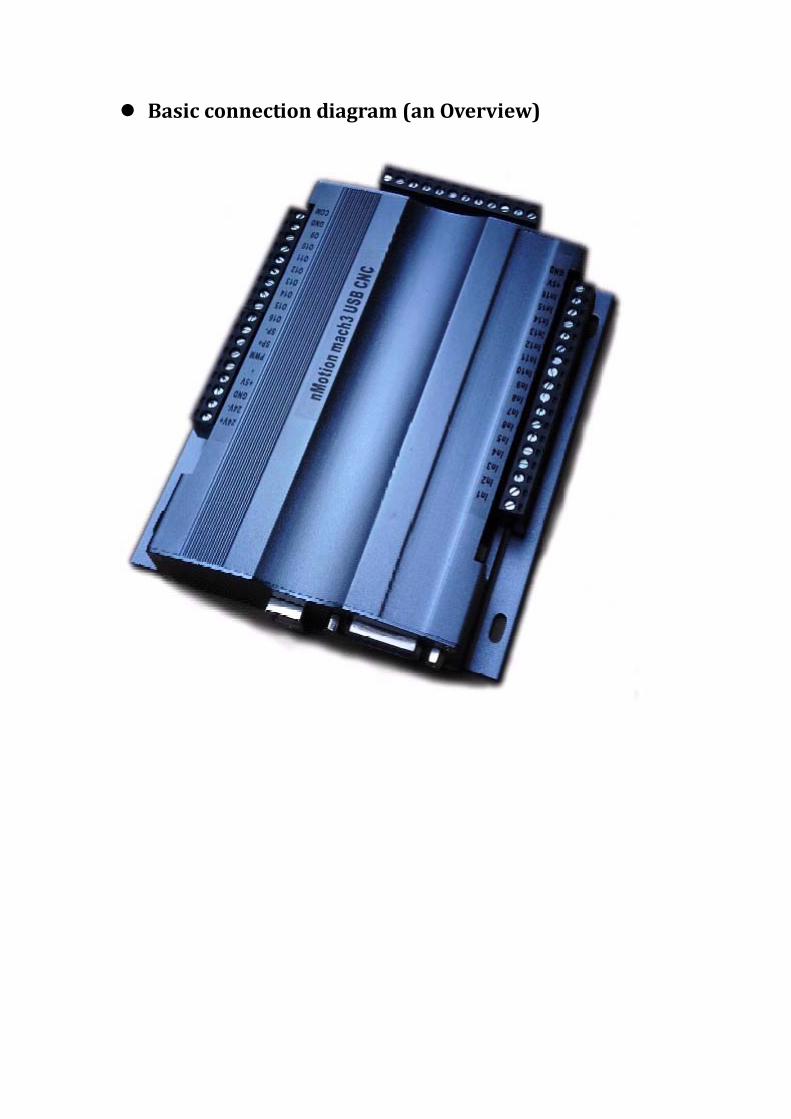
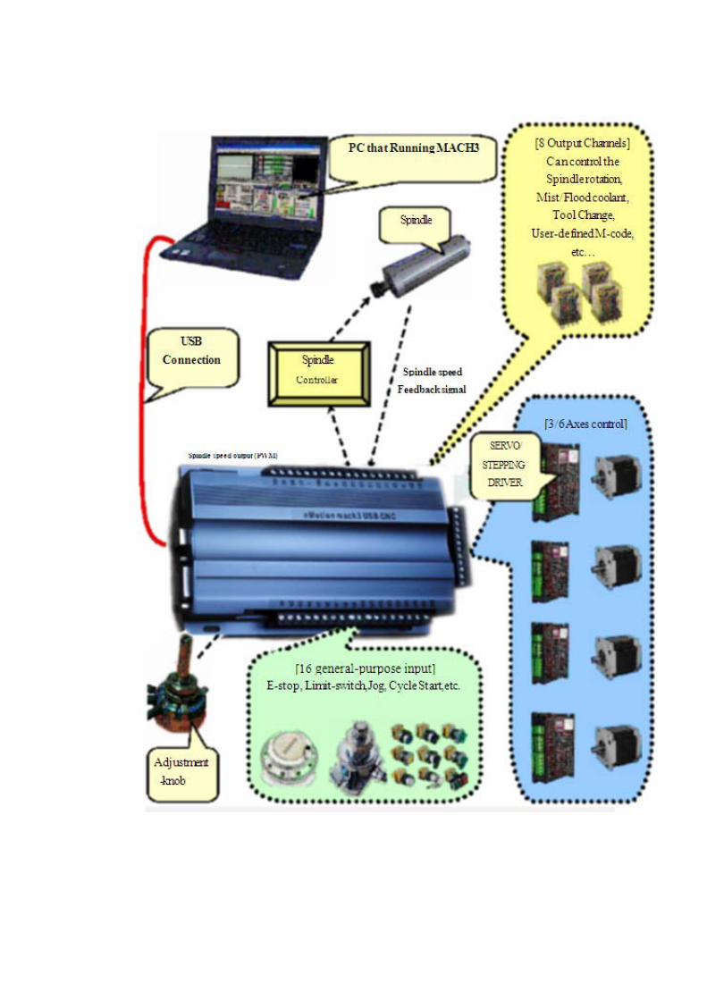
Basic connection diagram (an Overview)
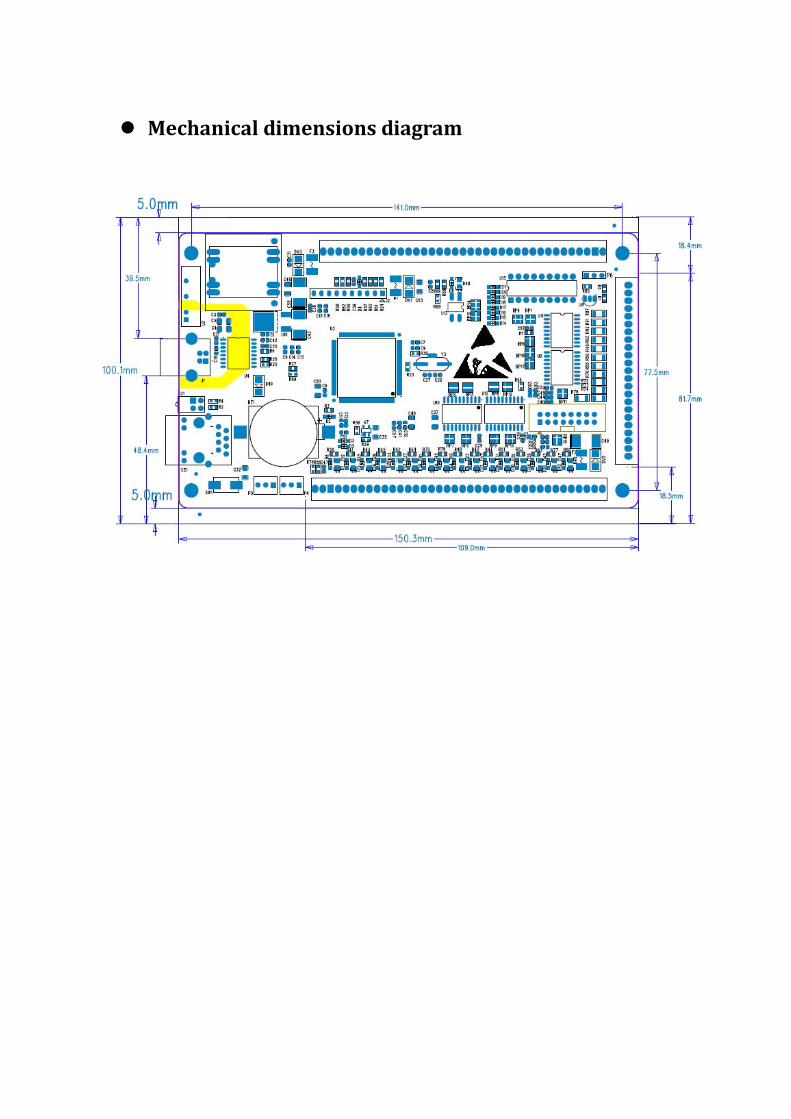
Mechanical dimensions diagram
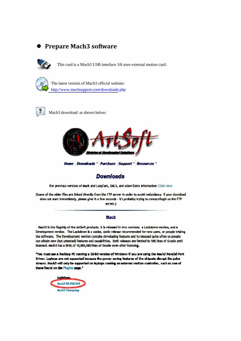
Prepare Mach3 software
This card is a Mach3 USB interface 3/6 axes external motion card。
The latest version of Mach3 official website: http://www.machsupport.com/downloads.php
Mach3 download: as shown below:
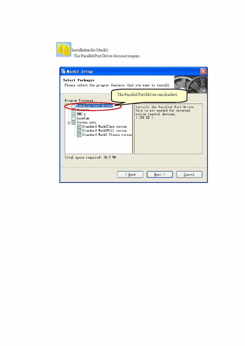
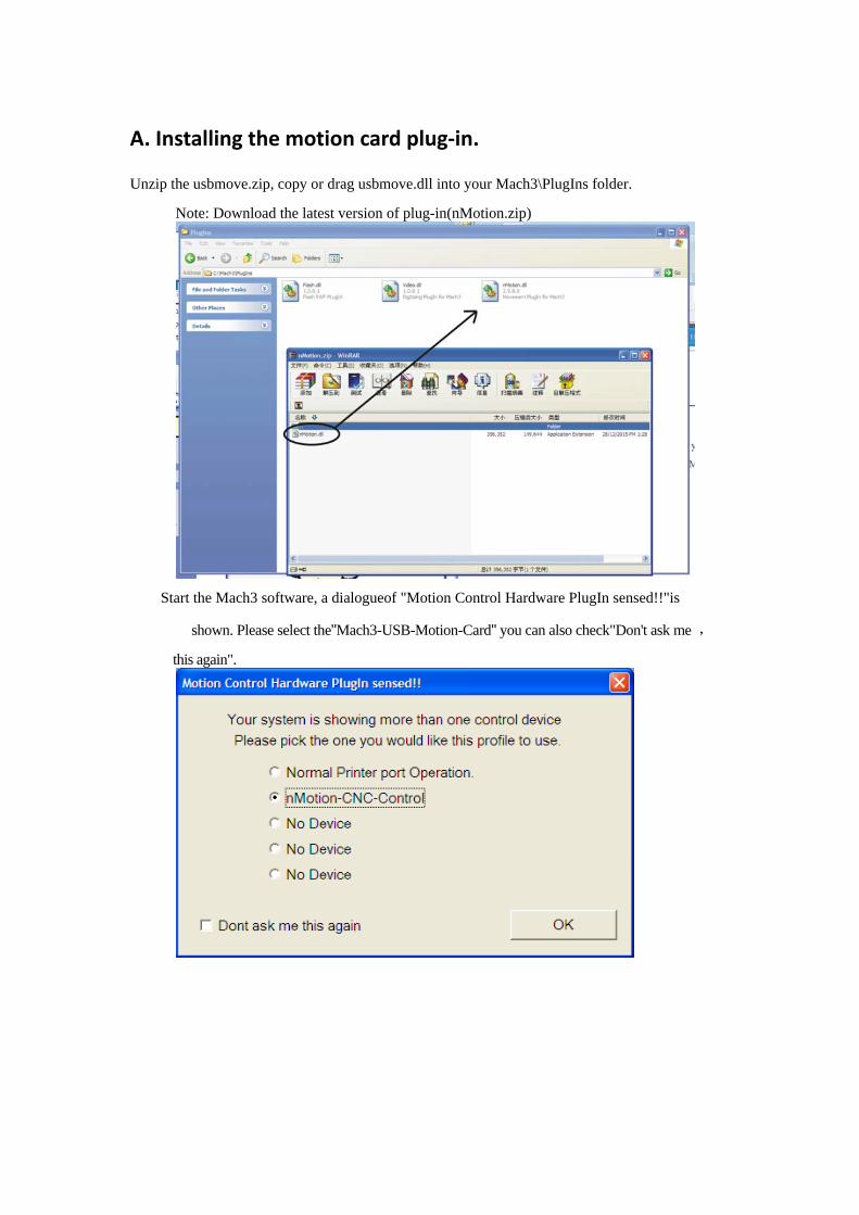
A. Installing the motion card plug‐in.
Unzip the usbmove.zip, copy or drag usbmove.dll into your Mach3\PlugIns folder.
Note: Download the latest version of plug-in(nMotion.zip)
Start the Mach3 software, a dialogueof "Motion Control Hardware PlugIn sensed!!"is
shown. Please select the"Mach3-USB-Motion-Card" you can also check"Don't ask me ,
this again".
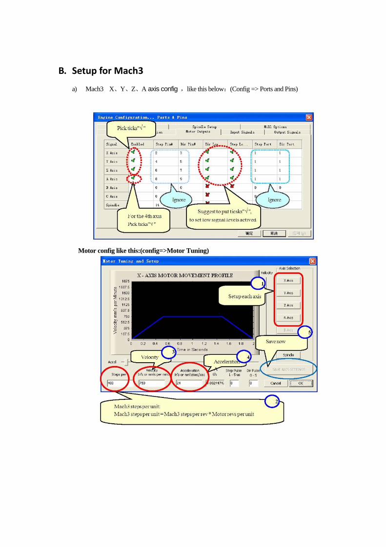
B. Setup for Mach3
a) Mach3 X、Y、Z、A axis config ,like this below:(Config => Ports and Pins)
Motor config like this:(config=>Motor Tuning)

The Mach3 Menu => Config => Homing/Limits dialog Axes direction, depends on the "Reversed".
Or you can chang the direction on this page: Dir Low selet “X” or “√”
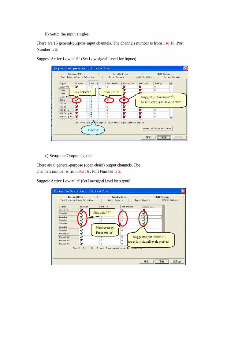
b) Setup the input singles.
There are 16 general-purpose input channels. The channels number is from 1 to 16 ,Port Number is 2.
Suggest Active Low ="√ " (Set Low signal Level for Inputs)
c) Setup the Output signals.
There are 8 general-purpose (open-drain) output channels, The channels number is from 9to 16 . Port Number is 2.
Suggest Active Low =" √" (Set Low signal Level for outputs)
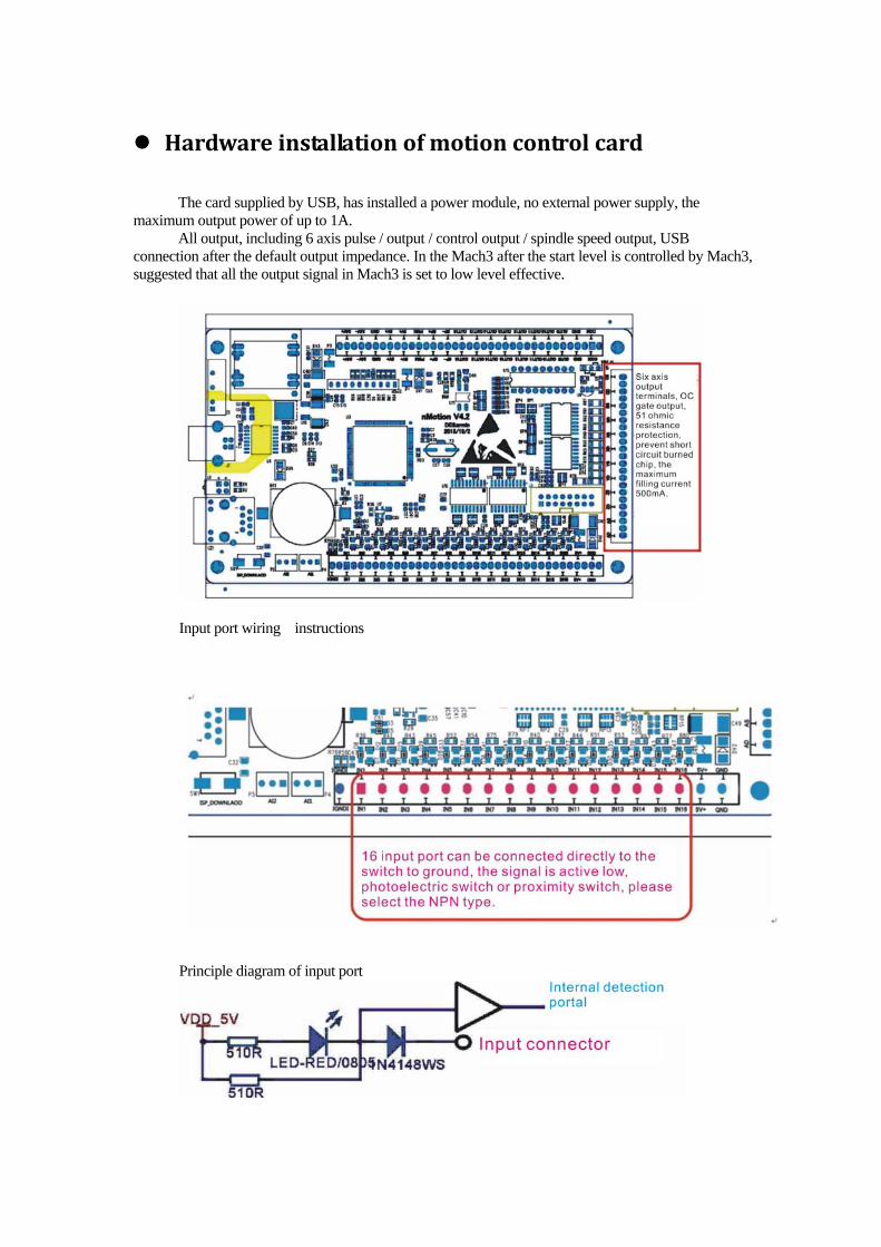
Hardware installation of motion control card The card supplied by USB, has installed a power module, no external power supply, the
maximum output power of up to 1A. All output, including 6 axis pulse / output / control output / spindle speed output, USB
connection after the default output impedance. In the Mach3 after the start level is controlled by Mach3, suggested that all the output signal in Mach3 is set to low level effective.
Input port wiring instructions
Principle diagram of input port
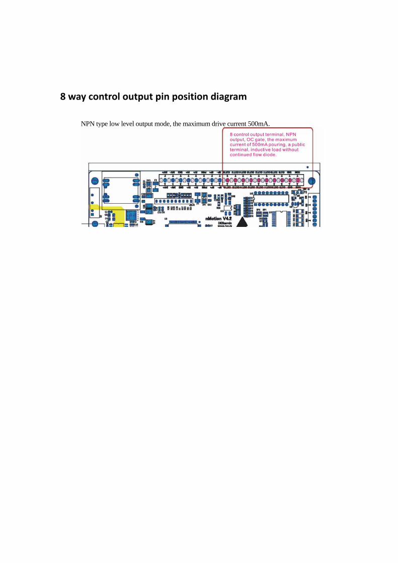
8 way control output pin position diagram
NPN type low level output mode, the maximum drive current 500mA.
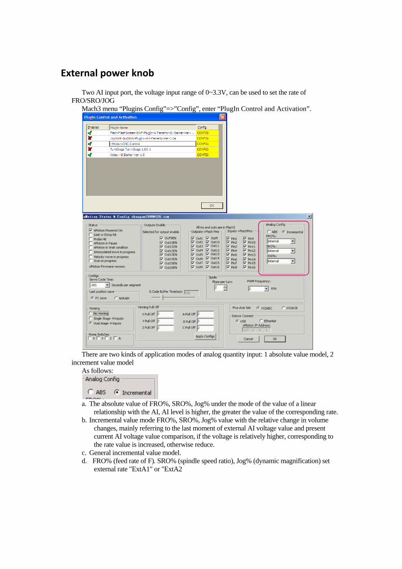
External power knob
Two AI input port, the voltage input range of 0~3.3V, can be used to set the rate of FRO/SRO/JOG
Mach3 menu “Plugins Config”=>”Config”, enter “PlugIn Control and Activation”.
There are two kinds of application modes of analog quantity input: 1 absolute value model, 2
increment value model As follows:
a. The absolute value of FRO%, SRO%, Jog% under the mode of the value of a linear
relationship with the AI, AI level is higher, the greater the value of the corresponding rate. b. Incremental value mode FRO%, SRO%, Jog% value with the relative change in volume
changes, mainly referring to the last moment of external AI voltage value and present current AI voltage value comparison, if the voltage is relatively higher, corresponding to the rate value is increased, otherwise reduce.
c. General incremental value model. d. FRO% (feed rate of F). SRO% (spindle speed ratio), Jog% (dynamic magnification) set
external rate "ExtA1" or "ExtA2
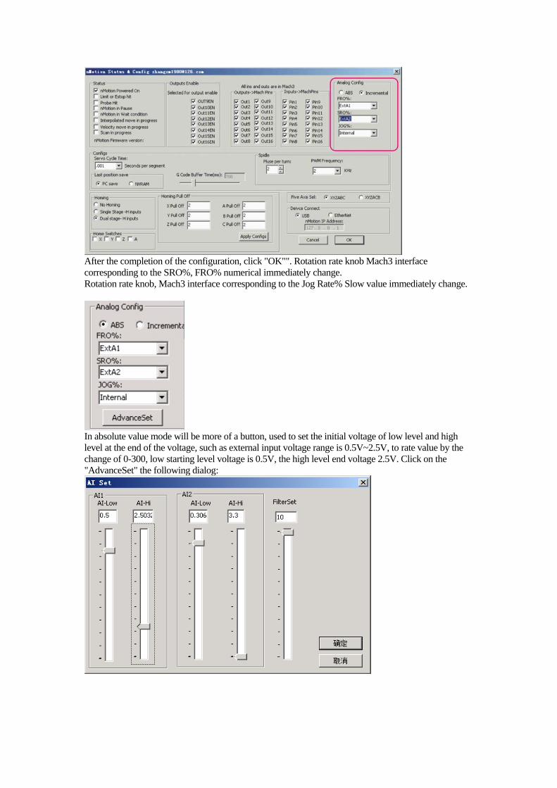
After the completion of the configuration, click "OK"". Rotation rate knob Mach3 interface corresponding to the SRO%, FRO% numerical immediately change. Rotation rate knob, Mach3 interface corresponding to the Jog Rate% Slow value immediately change.
In absolute value mode will be more of a button, used to set the initial voltage of low level and high level at the end of the voltage, such as external input voltage range is 0.5V~2.5V, to rate value by the change of 0-300, low starting level voltage is 0.5V, the high level end voltage 2.5V. Click on the "AdvanceSet" the following dialog:
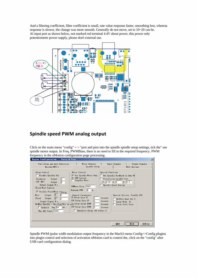
And a filtering coefficient, filter coefficient is small, rate value response faster, smoothing less, whereas response is slower, the change was more smooth. Generally do not move, set to 10~20 can be. AI input port as shown below, not marked red terminal 4.4V about power, this power only potentiometer power supply, please don't external use.
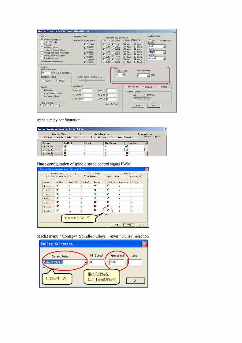
Spindle speed PWM analog output
Click on the main menu "config" = > "port and pins into the spindle spindle setup settings, tick the" use spindle motor output. In Freq. PWMBase, there is no need to fill in the required frequency. PWM frequency in the nMotion configuration page processing.
Spindle PWM (pulse width modulation output frequency in the Mach3 menu Config=>Config plugins into plugin control and selection of activation nMotion card to control the, click on the "config" after USB card configuration dialog.
spindle relay configuration
Phase configuration of spindle speed control signal PWM
Mach3 menu " Config=> Spindle Pulleys ", enter " Pulley Selection "

Principle diagram of the spindle speed control analog output interface
VCC_10V have not served , if you use a variable frequency speed control of the spindle and need in PWM feet pick a pull-up resistor to inverter 10V output ports.
nMotion control card of the speed of the input interface schematic

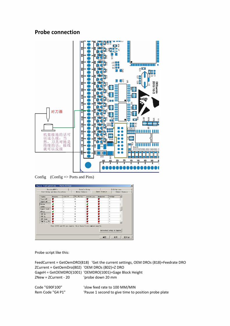
Probe connection
Config (Config => Ports and Pins)
Probe script like this: FeedCurrent = GetOemDRO(818) 'Get the current settings, OEM DROs (818)=Feedrate DRO ZCurrent = GetOemDro(802) 'OEM DROs (802)=Z DRO GageH = GetOEMDRO(1001) 'OEMDRO(1001)=Gage Block Height ZNew = ZCurrent ‐ 20 'probe down 20 mm Code "G90F100" 'slow feed rate to 100 MM/MIN Rem Code "G4 P1" 'Pause 1 second to give time to position probe plate

Code "G31 Z" &ZNew While IsMoving() Sleep(10) Wend Call SetDro (2,GageH) 'DRO(2)=Z DRO FinalMove = GageH + 10 Code "G0 Z" &FinalMove Code "F" &FeedCurrent 'restore starting feed rate dr.lin 2009.10.16
MPG Setting
MPG use the input pin IN15 and IN16 , connect to Encode A and B signal.
If you use a full function MPG with Rate switch and Axis select,
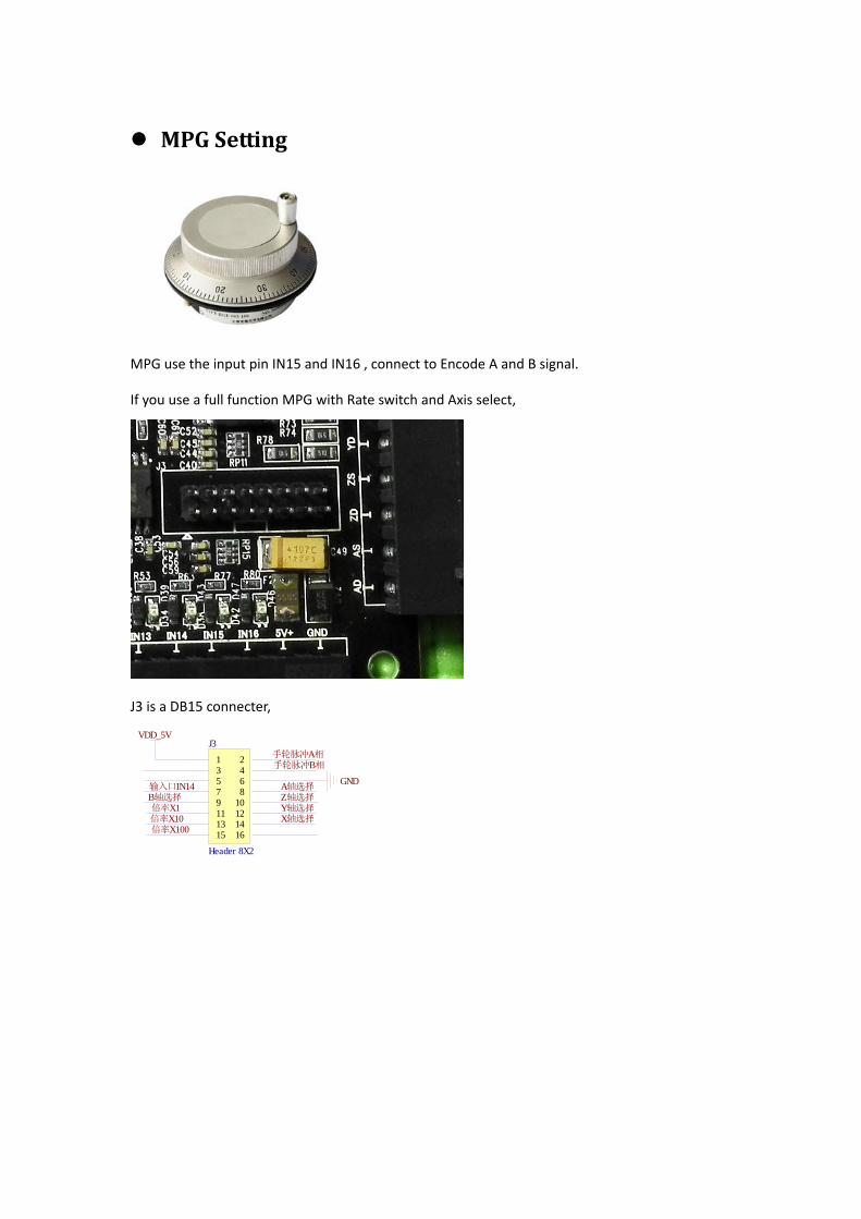
J3 is a DB15 connecter,
1 23 45 67 89 1011 1213 1415 16
J3
Header 8X2
VDD_5V
手轮脉冲A相手轮脉冲B相
GNDA轴选择Z轴选择Y轴选择X轴选择
输入口IN14B轴选择倍率X1倍率X10倍率X100

If you have a Metal shell with nMotion, the DB15 head is installed.
The DB15 head PIN order is like this :
1 +5V 9 Encoder A
2 10 Encoder B
3 11 GND
4 ESTOP 12 A axis SEL
5 B Axis SEL 13 Z axis SEL
6 X1 14 Y axis SEL
7 X10 15 X axis SEL
8 X100
Software configuration
Mach3 electronic hand wheel configuration, as shown below: (Config => Ports and Pins)
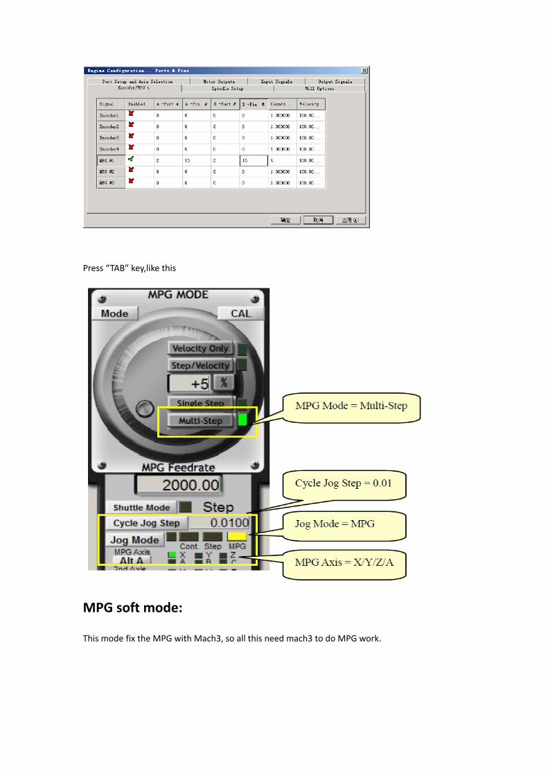
Press “TAB” key,like this
MPG soft mode:
This mode fix the MPG with Mach3, so all this need mach3 to do MPG work.
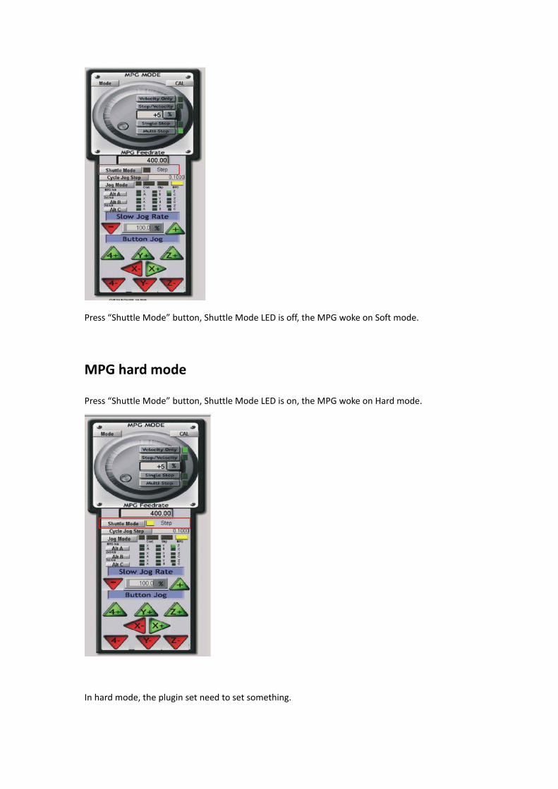
Press “Shuttle Mode” button, Shuttle Mode LED is off, the MPG woke on Soft mode.
MPG hard mode
Press “Shuttle Mode” button, Shuttle Mode LED is on, the MPG woke on Hard mode.
In hard mode, the plugin set need to set something.
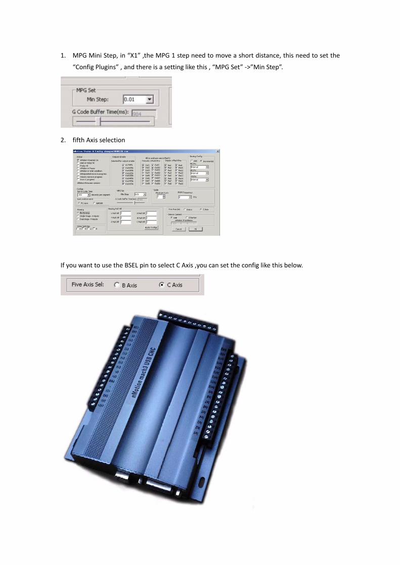
1. MPG Mini Step, in “X1” ,the MPG 1 step need to move a short distance, this need to set the
“Config Plugins” , and there is a setting like this , “MPG Set” ‐>”Min Step”.
2. fifth Axis selection
If you want to use the BSEL pin to select C Axis ,you can set the config like this below.
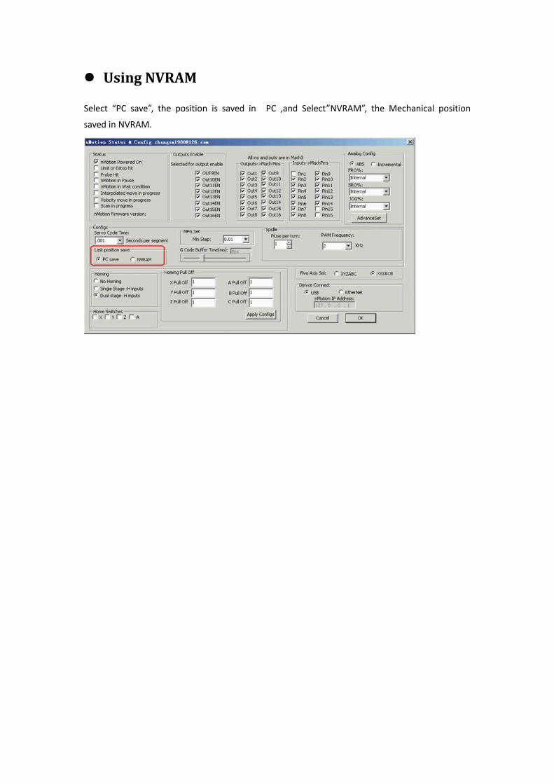
Using NVRAM
Select “PC save”, the position is saved in PC ,and Select”NVRAM”, the Mechanical position
saved in NVRAM.