NMDOT CADD Standards - dot.state.nm.us · NMDOT has committed to the implementation and support of...
134
CADD Drafting Standards May 2016
Transcript of NMDOT CADD Standards - dot.state.nm.us · NMDOT has committed to the implementation and support of...
CADD Drafting Standards May 2016

Section 1
January 2014 NMDOT CADD Drafting Standards
Trademarks All vendor names, brand names and product names used in this document are service marks or trademarks of their respective owners. MJM Consulting, LLC is not associated with any product or vendor mentioned in this document.
Software Versions
AutoCAD Civil 3D 2013
AutoCAD Civil 3D 2014
AutoCAD Civil 3D 2015
AutoCAD Civil 3D 2016
Author This document prepared for the New Mexico Department of Transportation by:
MJM Consulting, LLC
Version Document version 07052016.01
This document is formatted for double-sided printing.
Legal Statements
NMDOT CADD Drafting Standards January 2014
The page intentionally left blank.
Section 1
January 2014 NMDOT CADD Drafting Standards
Contents Trademarks ................................................................................................................................................................... 3
Software Versions ........................................................................................................................................................ 3
Author ............................................................................................................................................................................ 3
Version ........................................................................................................................................................................... 3
1: Overview ...................................................................................................................................................................... 9
What’s New ................................................................................................................................................................10
Purpose ........................................................................................................................................................................10
CADD Platforms .........................................................................................................................................................10
Glossary of Terms .......................................................................................................................................................11
Paradigms ...................................................................................................................................................................13
Typefaces: ...............................................................................................................................................................13
Symbols: ...................................................................................................................................................................13
2: Directory Structure ....................................................................................................................................................15
Project Directory Structure .......................................................................................................................................16
Detailed Summary of Directories ........................................................................................................................17
PCN Explained .......................................................................................................................................................19
Primary Sub Directories .........................................................................................................................................19
_data........................................................................................................................................................................20
Construction ...........................................................................................................................................................20
Existing .....................................................................................................................................................................21
ITS ..............................................................................................................................................................................21
Project_Resources .................................................................................................................................................22
PDE ...........................................................................................................................................................................22
Plans .........................................................................................................................................................................22
Proposed .................................................................................................................................................................23
PSE_ENGR ................................................................................................................................................................23
3: Project Plan Sets .......................................................................................................................................................25
Planimetric vs. Informational ...................................................................................................................................26
Basic Numbering Scheme .......................................................................................................................................26
4: File Naming Conventions ........................................................................................................................................29
Base Files vs. Sheet Files ............................................................................................................................................30
Standard Base Files ...............................................................................................................................................30
Standard Sheet Files ..............................................................................................................................................31
5: Borders and Covers ..................................................................................................................................................33
Legal Statements
NMDOT CADD Drafting Standards January 2014
Border Use ...................................................................................................................................................................34
Border Dimensions .....................................................................................................................................................34
Plan and Profile Generation ....................................................................................................................................35
Consultant Logos .......................................................................................................................................................36
Covers ..........................................................................................................................................................................37
Sheet Set Manager ...................................................................................................................................................37
6: Template Files ............................................................................................................................................................39
Template Files .............................................................................................................................................................40
Units ..............................................................................................................................................................................40
Coordinate Systems ..................................................................................................................................................41
Angles ..........................................................................................................................................................................42
Layouts ........................................................................................................................................................................42
Sheet Naming ........................................................................................................................................................43
View Ports ................................................................................................................................................................44
7: Reference Files ..........................................................................................................................................................45
Reference File Usage ................................................................................................................................................46
Reference Pathing ....................................................................................................................................................46
8: Layers ..........................................................................................................................................................................47
AutoCAD Layers ........................................................................................................................................................48
ByLayer Attributes ......................................................................................................................................................48
Layering Schema ......................................................................................................................................................49
Survey Layers ..........................................................................................................................................................49
Aerial Layers ...........................................................................................................................................................62
General Layers .......................................................................................................................................................69
Bridge Layers ..........................................................................................................................................................76
Drainage Layers .....................................................................................................................................................87
Utilities Layers ..........................................................................................................................................................91
Road Layers ............................................................................................................................................................95
Traffic Layers ........................................................................................................................................................ 102
Level Filters ............................................................................................................................................................... 107
9: Symbology............................................................................................................................................................... 109
Weights ..................................................................................................................................................................... 110
AutoCAD Weight .................................................................................................................................................... 110
Linetypes .................................................................................................................................................................. 110
Colors ........................................................................................................................................................................ 111
Gray Scaling and RGB values .......................................................................................................................... 111

Section 1
January 2014 NMDOT CADD Drafting Standards
10: Annotation ............................................................................................................................................................ 113
NMDOT Standard Fonts ......................................................................................................................................... 114
Text Sizes ................................................................................................................................................................... 114
Text Justification ...................................................................................................................................................... 114
Special Characters ................................................................................................................................................ 114
Additional Default Symbols .............................................................................................................................. 115
Fields ......................................................................................................................................................................... 115
11: Cell Libraries/Blocks ............................................................................................................................................ 117
NMDOT Block Libraries ........................................................................................................................................... 118
Block Attributes ....................................................................................................................................................... 118
12: Dimensioning ........................................................................................................................................................ 119
Geometry ................................................................................................................................................................. 120
Units ........................................................................................................................................................................... 120
Text ............................................................................................................................................................................ 120
Symbology ............................................................................................................................................................... 120
13: Plotting ................................................................................................................................................................... 121
NMDOT Plotting Standards ................................................................................................................................... 122
AutoCAD STB files ................................................................................................................................................... 122
14: Acceptable Delivery Formats .......................................................................................................................... 126
.DWG formats .......................................................................................................................................................... 127
Packaging ............................................................................................................................................................... 127
15: NMDOT Consultant Workspace ........................................................................................................................ 128
Consultant Deliverable Workspace .................................................................................................................... 129
16: Georeferenced Imaging .................................................................................................................................... 131
Imaging Standard .................................................................................................................................................. 132
Compression............................................................................................................................................................ 132
Index ............................................................................................................................................................................. 133

Legal Statements
NMDOT CADD Drafting Standards January 2014
The page intentionally left blank.
Section 1
January 2014 NMDOT CADD Drafting Standards
1: Overview This manual was created for the New Mexico Department of Transportation to assist in standardizing Computer Aided Drafting and Design (CADD) deliverables produced within, and for, the department. Items in this section:
What’s New
Purpose
CADD Platforms
Glossary of Terms
Paradigms
Section 1
NMDOT CADD Drafting Standards January 2014
What’s New The following changes have been made to this document:
• MicroStation references have been removed throughout the document • Multiple templates discussed • Project Resources folder discussed • Sheet Set Manager discussed • Template units defined as Feet, not Survey Feet • View Ports are discussed • Layering has been updated (duplicates removed and missing layers have been added)
Purpose The purpose of this manual is to establish and document standards to be utilized for all civil engineering projects developed for NMDOT, regardless of the entity creating the plans.
The creation of electronic files is merely the initial process of their life span. Project files are shared and referenced by many individuals. Establishing standards allows individuals to reliably utilize project files with predictable results and behaviors.
This manual presents these standards in a format that is easily understood by any individual with basic CADD knowledge. The contract between NMDOT and its consultants, or contractors define the exact terms and conditions regarding procedures and standards to be followed.
CADD Platforms NMDOT has committed to the implementation and support of AutoCAD Civil 3D on future projects. NMDOT’s currently supported versions of software are:
• AutoCAD Civil 3D 2013 • AutoCAD Civil 3D 2014 • AutoCAD Civil 3D 2015 • AutoCAD Civil 3D 2016
As of this publication date, Autodesk Civil 3D 2017 is not supported, nor should it be used for any NMDOT projects due to compatibility issues.
Section 1
January 2014 NMDOT CADD Drafting Standards
Glossary of Terms
.ctb – An AutoCAD plot style that is based on the color of the object to determine color, line weight (thickness), or linetype. Changing the color of an object will modify the printed results.
.dwg – Default file extension for files created by AutoCAD.
.stb – An AutoCAD plot style that allows the properties of the element to determine the printed results. Each element has properties that determine color, line weight (thickness), and linetype.
AutoCAD - CAD platform designed by Autodesk, Inc.
Base File –AutoCAD file created with design elements to be used as a reference file only.
Block– A group of elements created for use as a single element repeatedly. Blocks are stored within the AutoCAD drawing file.
CAD – Acronym for Computer Aided Drafting.
CADD – Acronym for Computer Aided Drafting & Design.
Color Table – Used to assign specific colors to elements using numeric values.
Consultant Deliverable Guidelines – Document detailing consultant deliverable requirements, namely digital file submission.
Extended Characters – Special symbol characters located within an AutoCAD or TrueType font resource file.
Layers – An element in a CAD file in which CAD programs segregate information for the user to aid in the display of the design. For example, the centerline of a roadway may be placed on a level named “VF-ROAD-CNTR-P”. The striped centerline may be placed on another level named “VF-ROAD-CNTR-E”. The user would then have the ability to show one of these centerlines by merely turning off the other level.
Linear Elements – Made up of either lines or various types of arcs, linear elements account for a majority of a design file.
Macros – A simple “program” used in applications that assist in automating repetitive commands. An example of a macro would be to change the “case” of text from lower to upper throughout a design file.
PCN – Acronym for Project Control Number. A PCN is a numeric value assigned to every civil engineering project to aid the DOT in tracking the design.
Raster Images – An image used in a design file to display either the project area, or a specific item within the project (i.e. a scanned New Mexico map to show location of project on the vicinity map). “Raster image” is typically used in reference to an Aerial photograph.
Reference File – A term used to describe a source file when the information is viewed from another file. A reference file is typically a base file used for information for the sheet file (i.e. plan and profile sheet).
Share – Folders located on a server with user and/or group permissions.
Servername – Example name of a server on the NMDOT Domain or a corporate domain.
Sharename – Example name of folder “shared” on the NMDOT servers or a corporate server.
Section 1
NMDOT CADD Drafting Standards January 2014
Sheet File – Design files that reference base files in order to display information in a manageable fashion. Sheet files are the files that are printed to create the plan set for any given civil engineering project.
Symbology – This term refers to the weight, color, and style of vector elements in a design file.
UNC – Universal Naming Convention; designated by \\servername\sharename.
Vector Elements – Any element created within a CAD application is a vector element. The most common elements are lines and arcs. These elements are often the output of the engineering software.
Working Units – Working units are merely units of measurement used in a CAD file to determine distance.
Section 1
January 2014 NMDOT CADD Drafting Standards
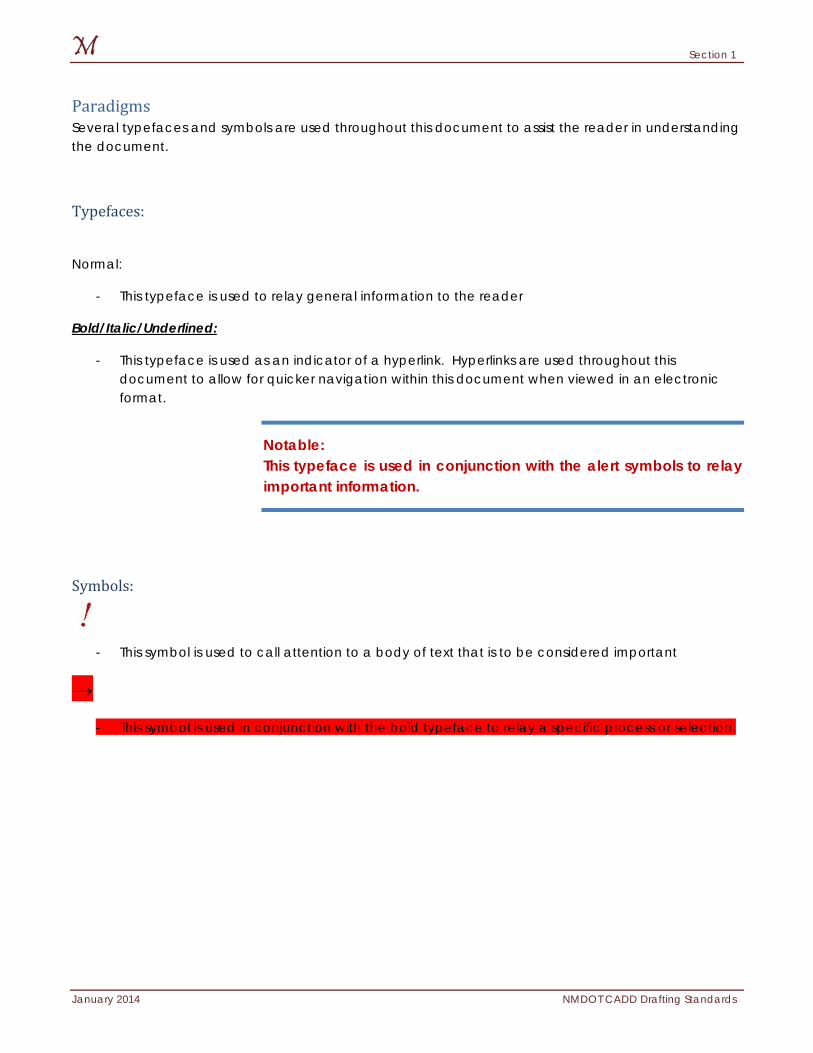
Paradigms Several typefaces and symbols are used throughout this document to assist the reader in understanding the document.
Typefaces:
Normal:
- This typeface is used to relay general information to the reader
Bold/Italic/Underlined:
- This typeface is used as an indicator of a hyperlink. Hyperlinks are used throughout this document to allow for quicker navigation within this document when viewed in an electronic format.
Notable: This typeface is used in conjunction with the alert symbols to relay important information.
Symbols:
- This symbol is used to call attention to a body of text that is to be considered important
→
- This symbol is used in conjunction with the bold typeface to relay a specific process or selection.
Section 1
NMDOT CADD Drafting Standards January 2014
The page intentionally left blank.
Section 2
January 2014 NMDOT CADD Drafting Standards
2: Directory Structure This section discusses the basis of the CADD environment: the directory structures. The two structures of utmost importance are the project directories. NMDOT has also created downloadable project template folders, which will create a similar directory structure on any local area network. In addition to the folders, the CADD Support Section has developed downloadable consultant workspaces, which should be utilized by all consultants doing work for the NMDOT (See Section 15 for additional information). The NMDOT requires all projects created for the State of New Mexico to follow certain criterion, and has created these files and workspace for this purpose. Items discussed in this section:
Project Directory Structure
CADD Standards Directory Structure
Section 2
NMDOT CADD Drafting Standards January 2014
Project Directory Structure The New Mexico Department of Transportation has developed a standard project directory structure to be utilized for all projects within the NMDOT. This includes deliverables submitted to the NMDOT by consulting firms performing work for the NMDOT. This project directory structure organizes the entire project within one main folder and departmentalizes the project by design disciplines. In addition to departmental directories, each project folder allocates directory locations for construction as-built drawings, completed Plans, and a Project_Resources directory for output files created for use in the current project.
This project workflow consists of existing and proposed design information, including a “Construction” folder for as-built data. Additionally, each project directory structure will include a “Plans” directory to store completed project design files for archival and if necessary, submission outside of the agency. This includes the project title sheets and vicinity map. The fifth and final primary folder, “Project_Resources”, is intended to store project files which may be generated, such as a project-specific block libraries.
The NMDOT project directory structure is to be adhered to unless given explicit, written permission from NMDOT to deviate. Any un-approved deviations from the project directory structure will be denied and the consultant will be responsible for the modifications necessary to meet the NMDOT standards.
Section 2
January 2014 NMDOT CADD Drafting Standards
Detailed Summary of Directories
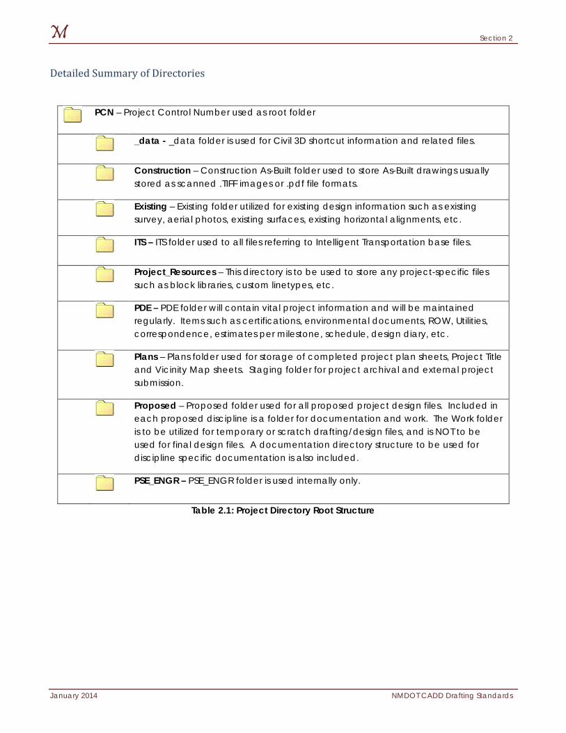
Table 2.1: Project Directory Root Structure
PCN – Project Control Number used as root folder
_data - _data folder is used for Civil 3D shortcut information and related files.
Construction – Construction As-Built folder used to store As-Built drawings usually stored as scanned .TIFF images or .pdf file formats.
Existing – Existing folder utilized for existing design information such as existing survey, aerial photos, existing surfaces, existing horizontal alignments, etc.
ITS – ITS folder used to all files referring to Intelligent Transportation base files.
Project_Resources – This directory is to be used to store any project-specific files such as block libraries, custom linetypes, etc.
PDE – PDE folder will contain vital project information and will be maintained regularly. Items such as certifications, environmental documents, ROW, Utilities, correspondence, estimates per milestone, schedule, design diary, etc.
Plans – Plans folder used for storage of completed project plan sheets, Project Title and Vicinity Map sheets. Staging folder for project archival and external project submission.
Proposed – Proposed folder used for all proposed project design files. Included in each proposed discipline is a folder for documentation and work. The Work folder is to be utilized for temporary or scratch drafting/design files, and is NOT to be used for final design files. A documentation directory structure to be used for discipline specific documentation is also included.
PSE_ENGR – PSE_ENGR folder is used internally only.
Section 2
NMDOT CADD Drafting Standards January 2014
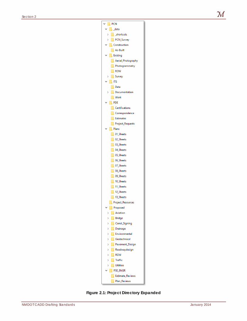
Figure 2.1: Project Directory Expanded
Section 2
January 2014 NMDOT CADD Drafting Standards
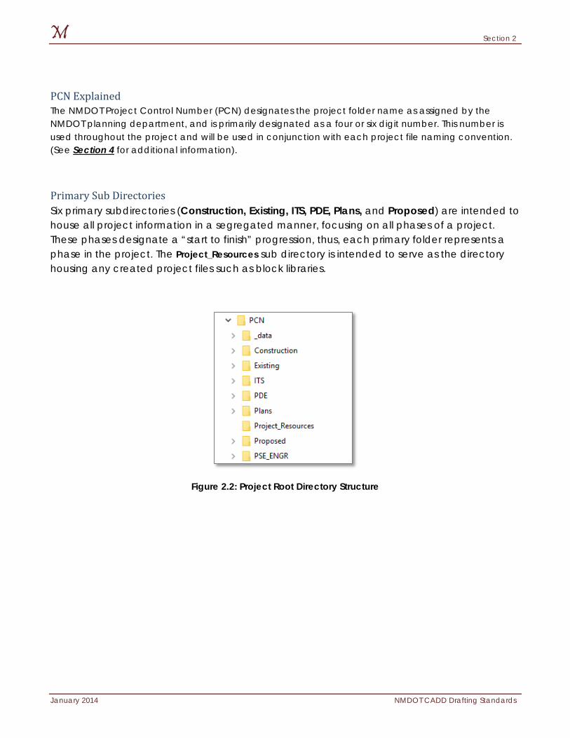
PCN Explained The NMDOT Project Control Number (PCN) designates the project folder name as assigned by the NMDOT planning department, and is primarily designated as a four or six digit number. This number is used throughout the project and will be used in conjunction with each project file naming convention. (See Section 4 for additional information).
Primary Sub Directories Six primary subdirectories (Construction, Existing, ITS, PDE, Plans, and Proposed) are intended to house all project information in a segregated manner, focusing on all phases of a project. These phases designate a “start to finish” progression, thus, each primary folder represents a phase in the project. The Project_Resources sub directory is intended to serve as the directory housing any created project files such as block libraries.
Figure 2.2: Project Root Directory Structure
Section 2
NMDOT CADD Drafting Standards January 2014
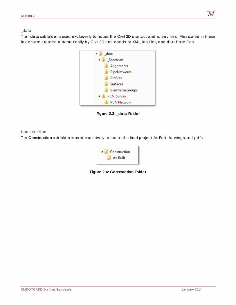
_data The _data subfolder is used exclusively to house the Civil 3D shortcut and survey files. Files stored in these folders are created automatically by Civil 3D and consist of XML, log files, and database files.
Figure 2.3: _data Folder
Construction The Construction subfolder is used exclusively to house the final project As-Built drawings and pdfs.
Figure 2.4: Construction Folder
Section 2
January 2014 NMDOT CADD Drafting Standards
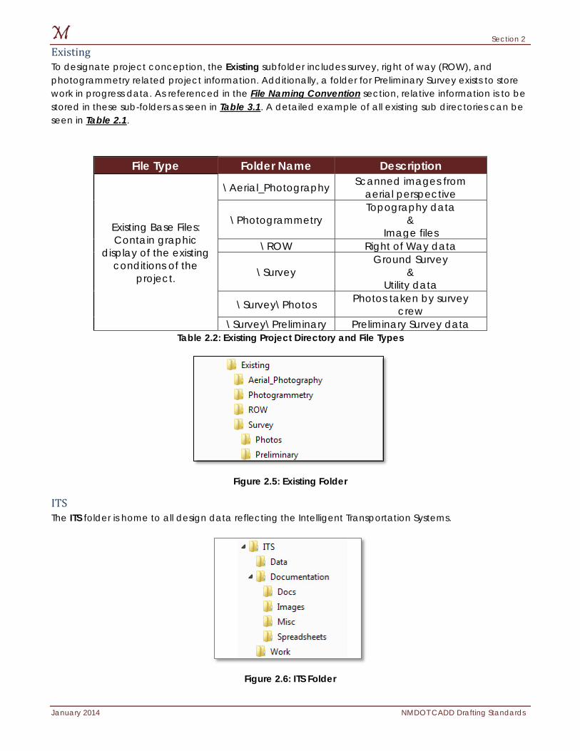
Existing To designate project conception, the Existing subfolder includes survey, right of way (ROW), and photogrammetry related project information. Additionally, a folder for Preliminary Survey exists to store work in progress data. As referenced in the File Naming Convention section, relative information is to be stored in these sub-folders as seen in Table 3.1. A detailed example of all existing sub directories can be seen in Table 2.1.
Table 2.2: Existing Project Directory and File Types
Figure 2.5: Existing Folder
ITS The ITS folder is home to all design data reflecting the Intelligent Transportation Systems.
Figure 2.6: ITS Folder
File Type Folder Name Description
Existing Base Files: Contain graphic
display of the existing conditions of the
project.
\Aerial_Photography Scanned images from aerial perspective
\Photogrammetry Topography data
& Image files
\ROW Right of Way data
\Survey Ground Survey
& Utility data
\Survey\Photos Photos taken by survey crew
\Survey\Preliminary Preliminary Survey data
Section 2
NMDOT CADD Drafting Standards January 2014
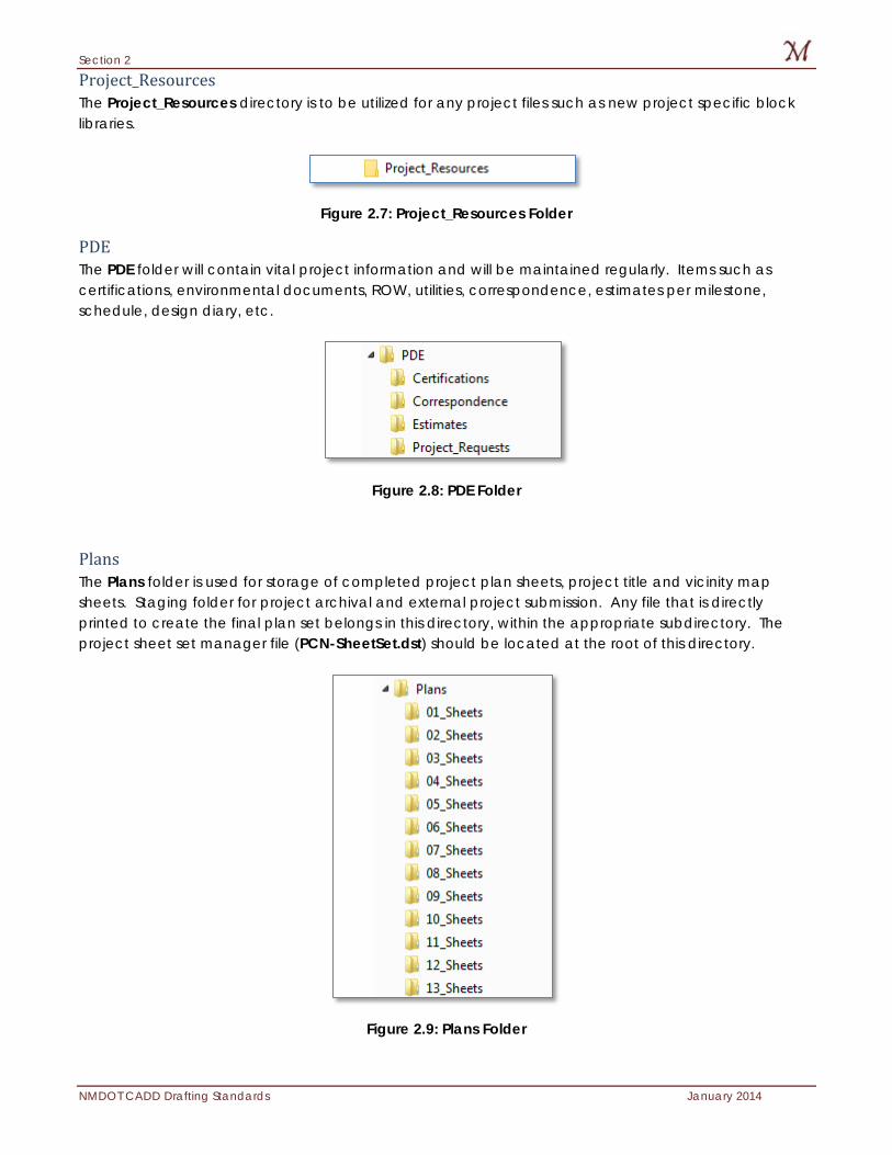
Project_Resources The Project_Resources directory is to be utilized for any project files such as new project specific block libraries.
Figure 2.7: Project_Resources Folder
PDE The PDE folder will contain vital project information and will be maintained regularly. Items such as certifications, environmental documents, ROW, utilities, correspondence, estimates per milestone, schedule, design diary, etc.
Figure 2.8: PDE Folder
Plans The Plans folder is used for storage of completed project plan sheets, project title and vicinity map sheets. Staging folder for project archival and external project submission. Any file that is directly printed to create the final plan set belongs in this directory, within the appropriate subdirectory. The project sheet set manager file (PCN-SheetSet.dst) should be located at the root of this directory.
Figure 2.9: Plans Folder
Section 2
January 2014 NMDOT CADD Drafting Standards
For the segregation and placement of the sheet files in a NMDOT project, refer to Section 3.
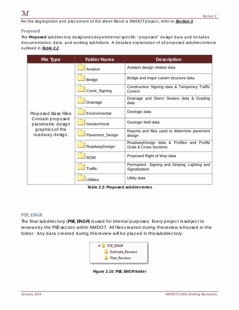
Proposed The Proposed subdirectory designates departmental specific “proposed” design data and includes documentation, data, and working subfolders. A detailed explanation of all proposed subdirectories is outlined in Table 2.2.
File Type Folder Name Description
Proposed Base Files: Contain proposed planimetric design
graphics of the roadway design.
Aviation Aviation design related data
Bridge Bridge and major culvert structure data
Const_Signing Construction Signing data & Temporary Traffic Control
Drainage Drainage and Storm Sewers data & Grading data
Environmental Geologic data
Geotechnical Geologic field data
Pavement_Design Reports and files used to determine pavement design
RoadwayDesign RoadwayDesign data & Profiles and Profile Grids & Cross Sections
ROW Proposed Right of Way data
Traffic Permanent Signing and Striping; Lighting and Signalization
Utilities Utility data
Table 2.3: Proposed subdirectories
PSE_ENGR The final subdirectory (PSE_ENGR) is used for internal purposes. Every project is subject to reviews by the PSE section within NMDOT. All files created during this review is housed in this folder. Any data created during this review will be placed in this subdirectory.
Figure 2.10: PSE_ENGR folder
Section 2
NMDOT CADD Drafting Standards January 2014
The page intentionally left blank.
Section 3
January 2014 NMDOT CADD Drafting Standards
3: Project Plan Sets The standard medium of a civil design project is the printed hard copies. These hard copies relay the information from survey, to design, to construction. It is vitally important that this information be standardized to simplify the exchange of information. In addition, standardization of this information has a positive impact on the many individuals who create these plan sets. This section discusses the project plan set as an entity and the elements these plan sets consist of. Items discussed in this section:
Planimetric vs. Informational
Basic Numbering Scheme
Section 3
NMDOT CADD Drafting Standards January 2014
Planimetric vs. Informational The standard civil design plan set is comprised of two general sheet types: planimetric and informational.
Planimetric sheets contain a plan (overhead) view of the design which is based on the NM State Plane Coordinate system 1983 or a NMDOT approved coordinate system. Examples of a planimetric sheet are: a plan and profile sheet, a striping sheet, or a lighting sheet.
Informational sheets can be graphical or non-graphical, and are not coordinate correct. A non-graphical sheet does not contain a view of the project, but merely contains project specific information, such as a summary of quantities. A graphical sheet does contain at least one view of the project, but does not have to be coordinate correct, such as a vicinity map of the project. Examples of an informational sheet would be a typical section sheet, a general notes sheet, or a border sheet.
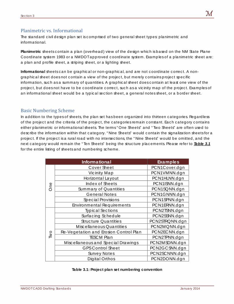
Basic Numbering Scheme In addition to the types of sheets, the plan set has been organized into thirteen categories. Regardless of the project and the criteria of the project, the categories remain constant. Each category contains either planimetric or informational sheets. The terms “One Sheets” and “Two Sheets” are often used to describe the information within that category. “Nine Sheets” would contain the signalization sheets for a project. If the project is a rural road with no intersections, the “Nine Sheets” would be omitted, and the next category would remain the “Ten Sheets” being the structure placements. Please refer to Table 3.1 for the entire listing of sheets and numbering scheme.
Table 3.1: Project plan set numbering convention
Informational Examples
One
Cover Sheet PCN1Cover.dgn Vicinity Map PCN1VMNN.dgn
Horizontal Layout PCN1HLNN.dgn Index of Sheets PCN1ISNN.dgn
Summary of Quantities PCN1SQNN.dgn General Notes PCN1GNNN.dgn
Special Provisions PCN1SPNN.dgn Environmental Requirements PCN1ERNN.dgn
Two
Typical Sections PCN2TSNN.dgn Surfacing Schedule PCN2SSNN.dgn Structure Quantities PCN2STRQNN.dgn
Miscellaneous Quantities PCN2MQNN.dgn Re-Vegetation and Erosion Control Plan PCN2ECNN.dgn
TESCM Plan PCN2TPNN.dgn Miscellaneous and Special Drawings PCN2MSDNN.dgn
GPS Control Sheet PCN2GCSNN.dgn Survey Notes PCN2SCNNN.dgn Digital Orthos PCN2DONN.dgn
Section 3
January 2014 NMDOT CADD Drafting Standards
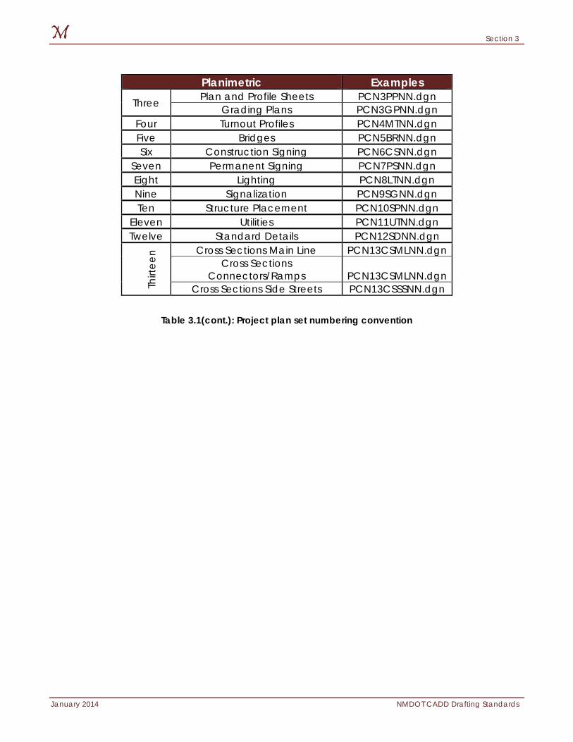
Table 3.1(cont.): Project plan set numbering convention
Planimetric Examples
Three Plan and Profile Sheets PCN3PPNN.dgn Grading Plans PCN3GPNN.dgn
Four Turnout Profiles PCN4MTNN.dgn Five Bridges PCN5BRNN.dgn Six Construction Signing PCN6CSNN.dgn
Seven Permanent Signing PCN7PSNN.dgn Eight Lighting PCN8LTNN.dgn Nine Signalization PCN9SGNN.dgn Ten Structure Placement PCN10SPNN.dgn
Eleven Utilities PCN11UTNN.dgn Twelve Standard Details PCN12SDNN.dgn
Thirt
een Cross Sections Main Line PCN13CSMLNN.dgn
Cross Sections Connectors/Ramps PCN13CSMLNN.dgn
Cross Sections Side Streets PCN13CSSSNN.dgn

Section 3
NMDOT CADD Drafting Standards January 2014
The page intentionally left blank.
Section 4
January 2014 NMDOT CADD Drafting Standards
4: File Naming Conventions NMDOT has developed a file naming convention that is to be applied in every project delivered to the department. This section also addresses workflow issues within the CADD application and the separation of sheet files and base files. Items discussed in this section:
Base files vs. Sheet Files
Standard Base files
Standard Sheet files
Section 4
NMDOT CADD Drafting Standards January 2014
Base Files vs. Sheet Files The term “base file” best describes a graphic design file containing project information such as planimetrics, cross sections, and profiles. The base file is referenced to multiple “sheet files” to display the project information in its entirety. Every element within a base file is created at a 1:1 scale. Text created in a base file must reflect the sheet file plotting scale (See Section 10 for additional information).
A “sheet file” is a design file containing a border, project information text, north arrows, and has base files referenced to display project information within a specific area. A sheet file is used to scale the project information to a specific plotting unit. Sheet file is the digital version of the hardcopy paper output. Sheet files are to be created regardless of CAD platform used in project development.
NMDOT requires the use of AutoCAD layouts. Annotation scaling must be used in all sheet files used to create an NMDOT plan set.
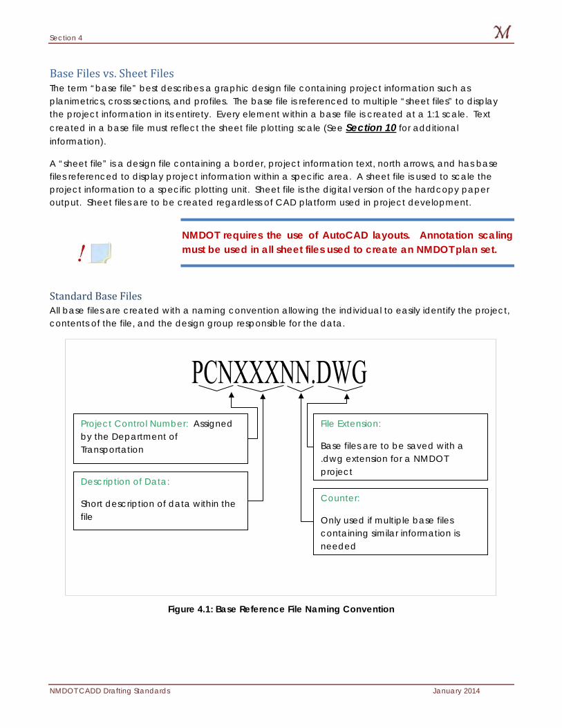
Standard Base Files All base files are created with a naming convention allowing the individual to easily identify the project, contents of the file, and the design group responsible for the data.
Figure 4.1: Base Reference File Naming Convention
Project Control Number: Assigned by the Department of Transportation
Description of Data:
Short description of data within the file
Counter:
Only used if multiple base files containing similar information is needed
File Extension:
Base files are to be saved with a .dwg extension for a NMDOT project
Section 4
January 2014 NMDOT CADD Drafting Standards
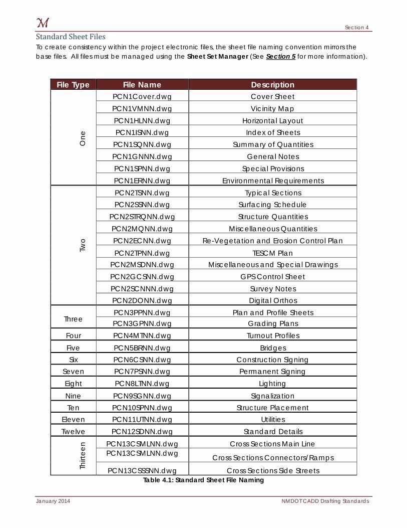
Standard Sheet Files To create consistency within the project electronic files, the sheet file naming convention mirrors the base files. All files must be managed using the Sheet Set Manager (See Section 5 for more information).
Table 4.1: Standard Sheet File Naming
File Type File Name Description O
ne
PCN1Cover.dwg Cover Sheet PCN1VMNN.dwg Vicinity Map PCN1HLNN.dwg Horizontal Layout PCN1ISNN.dwg Index of Sheets
PCN1SQNN.dwg Summary of Quantities PCN1GNNN.dwg General Notes PCN1SPNN.dwg Special Provisions PCN1ERNN.dwg Environmental Requirements
Two
PCN2TSNN.dwg Typical Sections PCN2SSNN.dwg Surfacing Schedule
PCN2STRQNN.dwg Structure Quantities PCN2MQNN.dwg Miscellaneous Quantities PCN2ECNN.dwg Re-Vegetation and Erosion Control Plan PCN2TPNN.dwg TESCM Plan
PCN2MSDNN.dwg Miscellaneous and Special Drawings PCN2GCSNN.dwg GPS Control Sheet PCN2SCNNN.dwg Survey Notes PCN2DONN.dwg Digital Orthos
Three PCN3PPNN.dwg Plan and Profile Sheets PCN3GPNN.dwg Grading Plans
Four PCN4MTNN.dwg Turnout Profiles Five PCN5BRNN.dwg Bridges Six PCN6CSNN.dwg Construction Signing
Seven PCN7PSNN.dwg Permanent Signing Eight PCN8LTNN.dwg Lighting Nine PCN9SGNN.dwg Signalization Ten PCN10SPNN.dwg Structure Placement
Eleven PCN11UTNN.dwg Utilities Twelve PCN12SDNN.dwg Standard Details
Thirt
een PCN13CSMLNN.dwg Cross Sections Main Line
PCN13CSMLNN.dwg Cross Sections Connectors/Ramps
PCN13CSSSNN.dwg Cross Sections Side Streets
Section 4
NMDOT CADD Drafting Standards January 2014
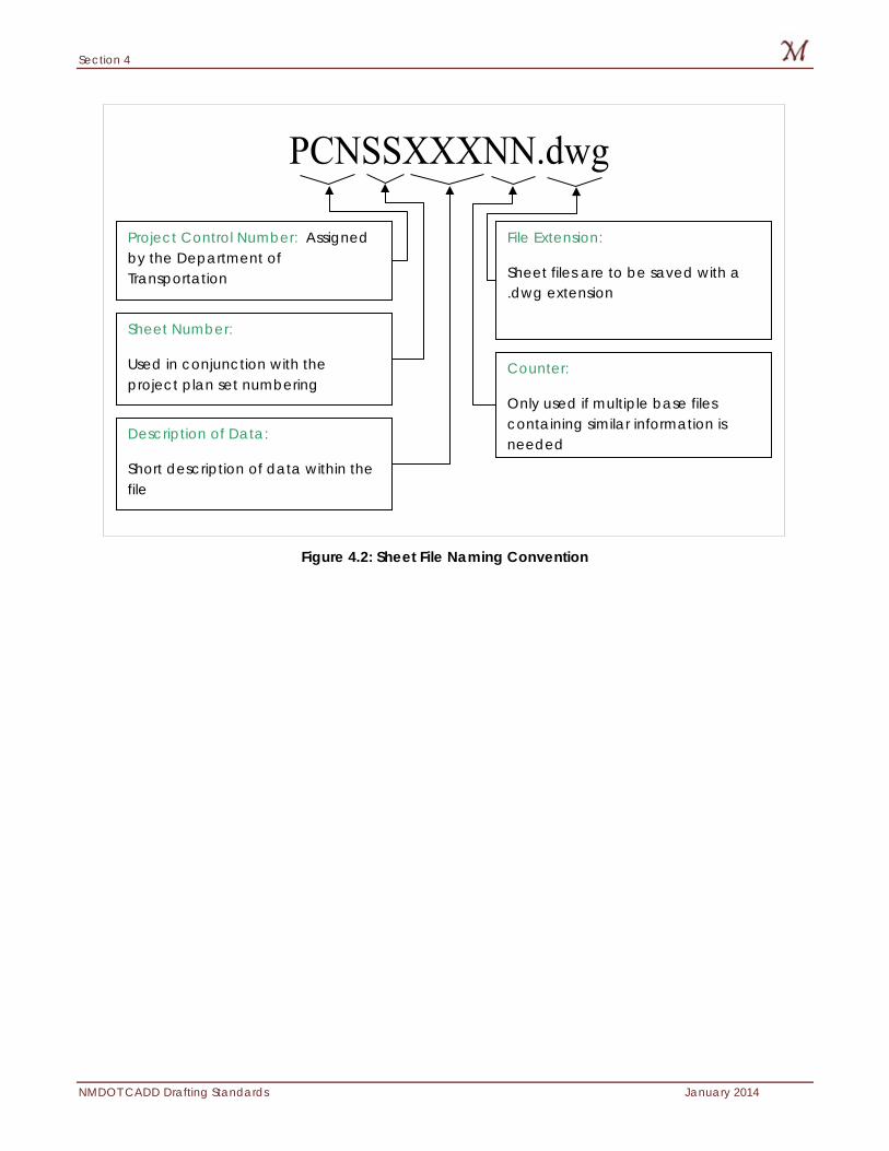
Figure 4.2: Sheet File Naming Convention
Project Control Number: Assigned by the Department of Transportation
Sheet Number:
Used in conjunction with the project plan set numbering
Counter:
Only used if multiple base files containing similar information is needed
File Extension:
Sheet files are to be saved with a .dwg extension
Description of Data:
Short description of data within the file
Section 5
January 2014 NMDOT CADD Drafting Standards
5: Borders and Covers Standard borders have been developed by New Mexico Department of Transportation for internal and external use. These borders are available on the internal Engineering Automation Bureau website and the external NMDOT website. This section discusses the NMDOT borders and their design. Items discussed in this section:
Border Use
Border Dimensions
Plan and Profile Generation
Consultant Logos
Covers
Sheet Set Manager
Section 5
NMDOT CADD Drafting Standards January 2014
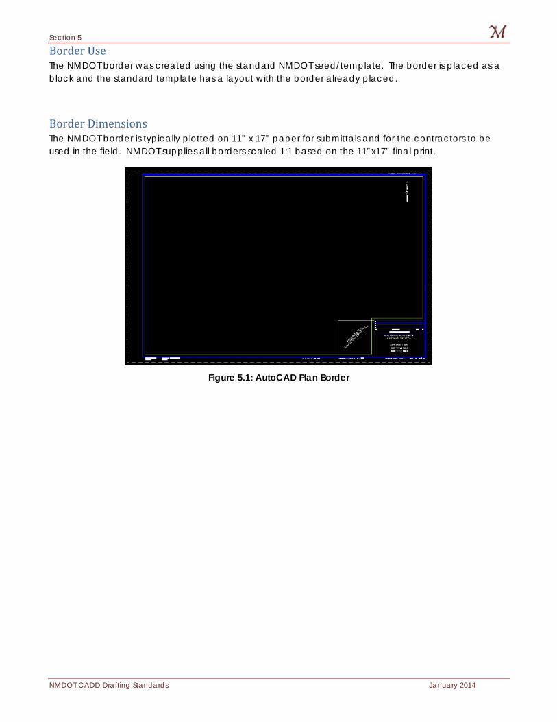
Border Use The NMDOT border was created using the standard NMDOT seed/template. The border is placed as a block and the standard template has a layout with the border already placed.
Border Dimensions The NMDOT border is typically plotted on 11” x 17” paper for submittals and for the contractors to be used in the field. NMDOT supplies all borders scaled 1:1 based on the 11”x17” final print.
Figure 5.1: AutoCAD Plan Border
Section 5
January 2014 NMDOT CADD Drafting Standards
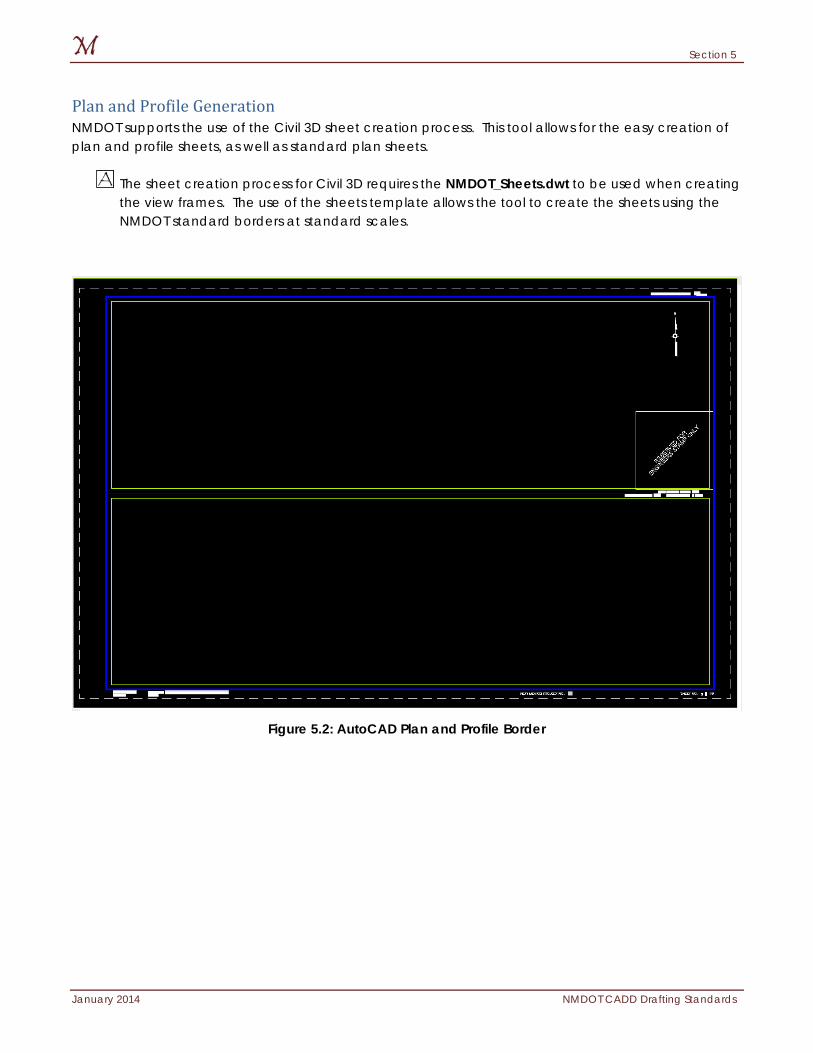
Plan and Profile Generation NMDOT supports the use of the Civil 3D sheet creation process. This tool allows for the easy creation of plan and profile sheets, as well as standard plan sheets.
The sheet creation process for Civil 3D requires the NMDOT_Sheets.dwt to be used when creating the view frames. The use of the sheets template allows the tool to create the sheets using the NMDOT standard borders at standard scales.
Figure 5.2: AutoCAD Plan and Profile Border
Section 5
NMDOT CADD Drafting Standards January 2014
Consultant Logos To help ensure standards are met on consultant deliverables, NMDOT has included an area in the cover sheets that may be used for consultant logos. An image, or vector elements, may be used in this area to create the consultant logo. The logo must plot correctly using the NMDOT standard plotting methods (see Section 13).
Section 5
January 2014 NMDOT CADD Drafting Standards
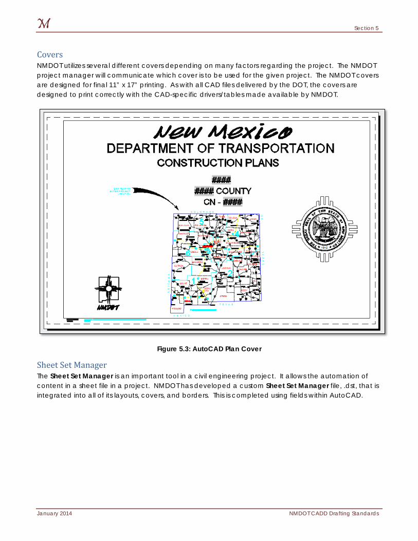
Covers NMDOT utilizes several different covers depending on many factors regarding the project. The NMDOT project manager will communicate which cover is to be used for the given project. The NMDOT covers are designed for final 11” x 17” printing. As with all CAD files delivered by the DOT, the covers are designed to print correctly with the CAD-specific drivers/tables made available by NMDOT.
Figure 5.3: AutoCAD Plan Cover
Sheet Set Manager The Sheet Set Manager is an important tool in a civil engineering project. It allows the automation of content in a sheet file in a project. NMDOT has developed a custom Sheet Set Manager file, .dst, that is integrated into all of its layouts, covers, and borders. This is completed using fields within AutoCAD.
Section 5
NMDOT CADD Drafting Standards January 2014
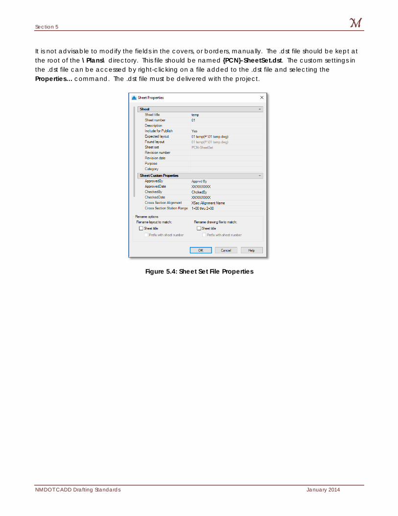
It is not advisable to modify the fields in the covers, or borders, manually. The .dst file should be kept at the root of the \Plans\ directory. This file should be named {PCN}-SheetSet.dst. The custom settings in the .dst file can be accessed by right-clicking on a file added to the .dst file and selecting the Properties… command. The .dst file must be delivered with the project.
Figure 5.4: Sheet Set File Properties
Section 6
January 2014 NMDOT CADD Drafting Standards
6: Template Files The standard NMDOT template files have been developed with careful consideration given to the design specifics of New Mexico projects. These files are the basis of all NMDOT design files and should be used throughout the project. It is paramount that the standards and settings discussed in this section be considered prior to, and during, the development of the project. Items discussed in this section:
Template Files
Units
Coordinate Systems
Angles
Layouts
View Ports
Section 6
NMDOT CADD Drafting Standards January 2014
Template Files NMDOT has separated its templates into three templates:
• NMDOT_Survey.dwt • NMDOT_Bridge.dwt • NMDOT.dwt
The reason for this separation is to minimize the amount of data used in one file. Autodesk files have the potential to gain large amounts of mass during the course of a civil engineering project. By searating the template, the resulting project files are smaller in size. Another reason for the separation is to minimize the potential of the wrong styles being utilized.
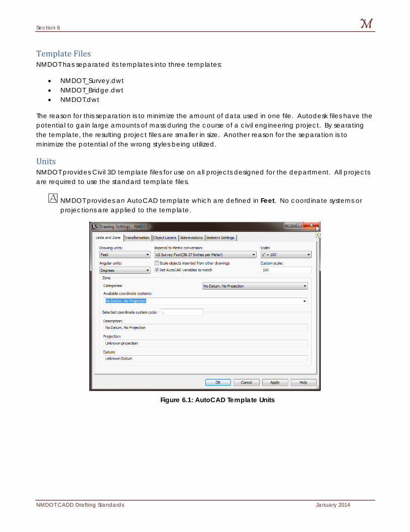
Units NMDOT provides Civil 3D template files for use on all projects designed for the department. All projects are required to use the standard template files.
NMDOT provides an AutoCAD template which are defined in Feet. No coordinate systems or projections are applied to the template.
Figure 6.1: AutoCAD Template Units
Section 6
January 2014 NMDOT CADD Drafting Standards
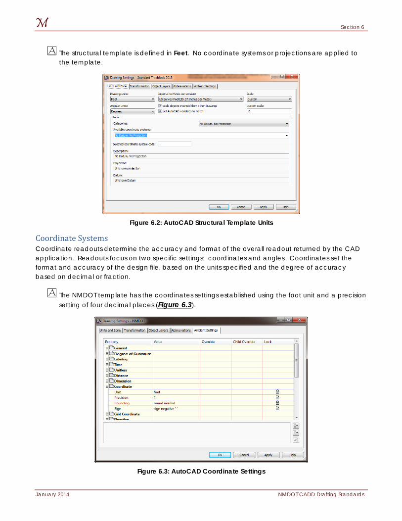
The structural template is defined in Feet. No coordinate systems or projections are applied to the template.
Figure 6.2: AutoCAD Structural Template Units
Coordinate Systems Coordinate readouts determine the accuracy and format of the overall readout returned by the CAD application. Readouts focus on two specific settings: coordinates and angles. Coordinates set the format and accuracy of the design file, based on the units specified and the degree of accuracy based on decimal or fraction.
The NMDOT template has the coordinates settings established using the foot unit and a precision setting of four decimal places (Figure 6.3).
Figure 6.3: AutoCAD Coordinate Settings
Section 6
NMDOT CADD Drafting Standards January 2014
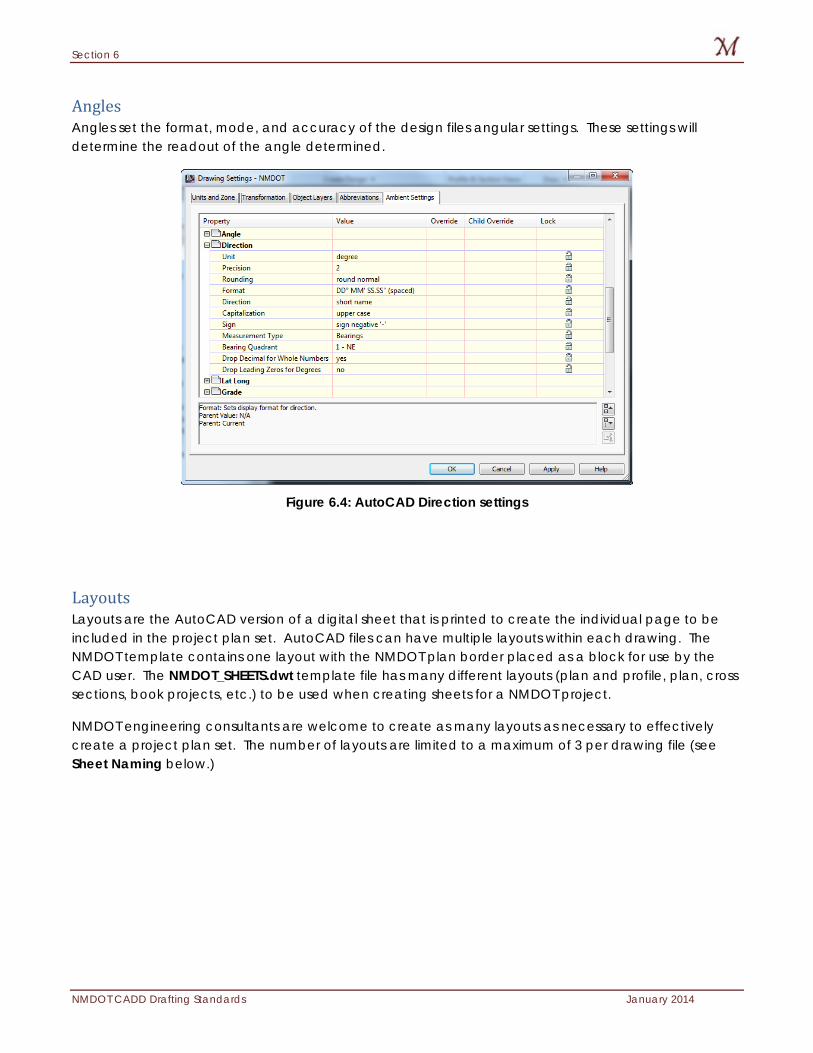
Angles Angles set the format, mode, and accuracy of the design files angular settings. These settings will determine the readout of the angle determined.
Figure 6.4: AutoCAD Direction settings
Layouts Layouts are the AutoCAD version of a digital sheet that is printed to create the individual page to be included in the project plan set. AutoCAD files can have multiple layouts within each drawing. The NMDOT template contains one layout with the NMDOT plan border placed as a block for use by the CAD user. The NMDOT_SHEETS.dwt template file has many different layouts (plan and profile, plan, cross sections, book projects, etc.) to be used when creating sheets for a NMDOT project.
NMDOT engineering consultants are welcome to create as many layouts as necessary to effectively create a project plan set. The number of layouts are limited to a maximum of 3 per drawing file (see Sheet Naming below.)
Section 6
January 2014 NMDOT CADD Drafting Standards
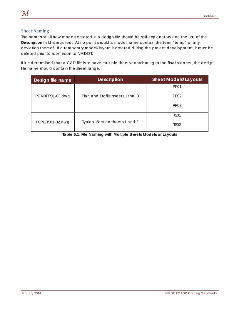
Sheet Naming The names of all new models created in a design file should be self-explanatory and the use of the Description field is required. At no point should a model name contain the term “temp” or any deviation thereof. If a temporary model/layout is created during the project development, it must be deleted prior to submission to NMDOT.
If it is determined that a CAD file is to have multiple sheets contributing to the final plan set, the design file name should contain the sheet range.
Design file name Description Sheet Models/Layouts
Plan and Profile sheets 1 thru 3
PP01
PCN3PP01-03.dwg PP02
PP03
PCN2TS01-02.dwg Typical Section sheets 1 and 2
TS01
TS02
Table 6.1: File Naming with Multiple Sheets Models or Layouts
Section 6
NMDOT CADD Drafting Standards January 2014
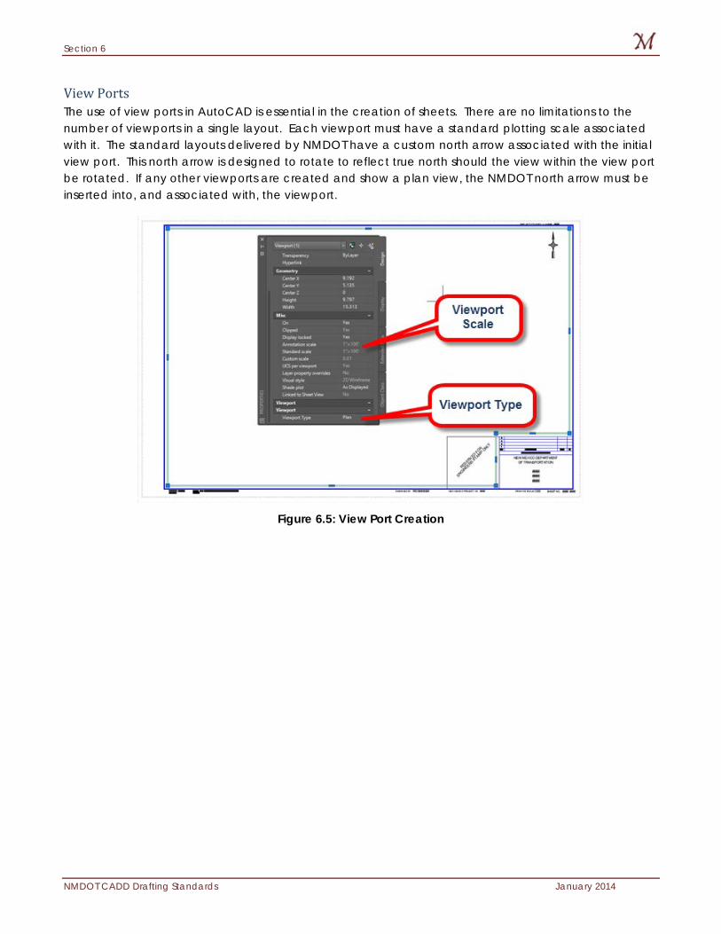
View Ports The use of view ports in AutoCAD is essential in the creation of sheets. There are no limitations to the number of viewports in a single layout. Each viewport must have a standard plotting scale associated with it. The standard layouts delivered by NMDOT have a custom north arrow associated with the initial view port. This north arrow is designed to rotate to reflect true north should the view within the view port be rotated. If any other viewports are created and show a plan view, the NMDOT north arrow must be inserted into, and associated with, the viewport.
Figure 6.5: View Port Creation
Section 7
January 2014 NMDOT CADD Drafting Standards
7: Reference Files Reference files are necessary for any creation of drawings and are used extensively throughout the NMDOT design process. The standard workflow of the NMDOT is to utilize references of design base files vs. copying all design information into a single design sheet. This method allows for segregation of design criteria while enabling “real time” updating of design changes. In addition, this method allows for separate level controls enabling the user to control the display of levels within each reference file while not affecting the active design file. Items discussed in this section:
Reference File Usage
Descriptions
Section 7
NMDOT CADD Drafting Standards January 2014
Reference File Usage The NMDOT’s use of reference files is critical to all aspects of project design and brings together multiple design disciplines into a “real time” viewing and editing process. This process becomes important when multiple design aspects, like drainage and roadway design interact on a project. In the case of a roadway widening project, the design team will need to reference the proposed drainage design (i.e. culvert design and locations) including existing contours to determine any potential issues with curb and gutter locations. This communication of information can be made available in “real time” between all departments simultaneously by utilizing reference files.
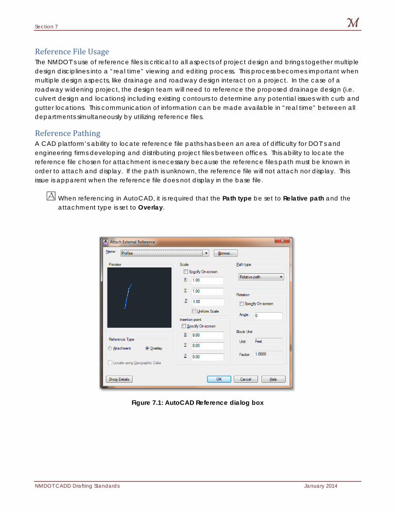
Reference Pathing A CAD platform’s ability to locate reference file paths has been an area of difficulty for DOT’s and engineering firms developing and distributing project files between offices. This ability to locate the reference file chosen for attachment is necessary because the reference files path must be known in order to attach and display. If the path is unknown, the reference file will not attach nor display. This issue is apparent when the reference file does not display in the base file.
When referencing in AutoCAD, it is required that the Path type be set to Relative path and the attachment type is set to Overlay.
Figure 7.1: AutoCAD Reference dialog box
Section 8
January 2014 NMDOT CADD Drafting Standards
8: Layers With the integration of Autodesk products as acceptable formats, NMDOT has changed the leveling structure to align with the National CAD Standards. While the NCS does not allow for major deviations for a government agency such as a department of transportation, NMDOT took liberties with the layering structure. These liberties allow the new laying structure to account for the design sections within the DOT and the types of projects the DOT develops and contracts to firms. Items discussed in this section:
ByLayer Attributes
Layering Schema
Layer Filters
Section 8
NMDOT CADD Drafting Standards January 2014
AutoCAD Layers AutoCAD layers have symbologies assigned to layers. NMDOT has developed the layering schema within its template file with ByLayer attributes aligned with the standards determined to be NMDOT requirements.
ByLayer Attributes The ability to assign symbologies to a level allows the use of a “ByLayer” setting (see Section 9 for additional information on symbology). Symbologies such as the color of elements, linetypes, and weights can now be assigned to levels. When a level is made the active level, the active weight, linetype and color will automatically be changed if the symbologies are set by-level.
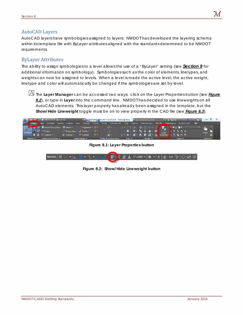
The Layer Manager can be accessed two ways: click on the Layer Properties button (see Figure 8.2), or type in Layer into the command line. NMDOT has decided to use lineweights on all AutoCAD elements. This layer property has already been assigned in the template, but the Show/Hide Lineweight toggle must be on to view properly in the CAD file (see Figure 8.3).
Figure 8.1: Layer Properties button
Figure 8.2: Show/Hide Lineweight button
Section 8
January 2014 NMDOT CADD Drafting Standards
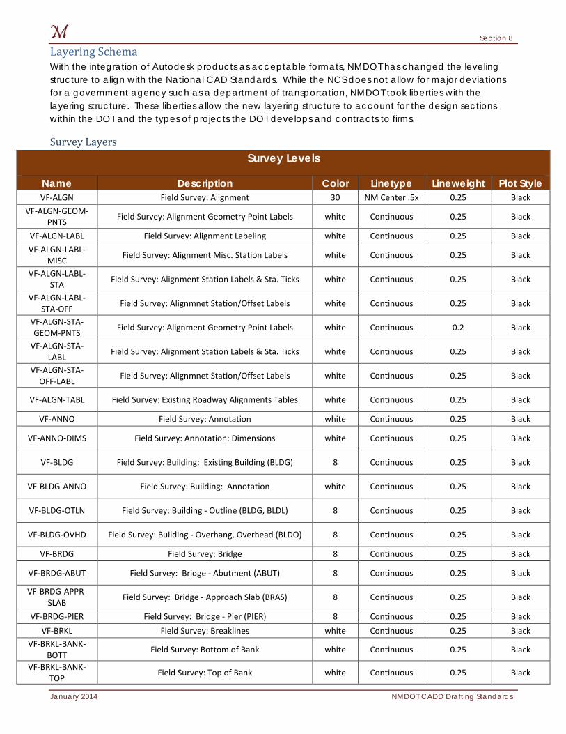
Layering Schema With the integration of Autodesk products as acceptable formats, NMDOT has changed the leveling structure to align with the National CAD Standards. While the NCS does not allow for major deviations for a government agency such as a department of transportation, NMDOT took liberties with the layering structure. These liberties allow the new layering structure to account for the design sections within the DOT and the types of projects the DOT develops and contracts to firms.
Survey Layers
Survey Levels
Name Description Color Linetype Lineweight Plot Style VF-ALGN Field Survey: Alignment 30 NM Center .5x 0.25 Black
VF-ALGN-GEOM-PNTS Field Survey: Alignment Geometry Point Labels white Continuous 0.25 Black
VF-ALGN-LABL Field Survey: Alignment Labeling white Continuous 0.25 Black VF-ALGN-LABL-
MISC Field Survey: Alignment Misc. Station Labels white Continuous 0.25 Black
VF-ALGN-LABL-STA Field Survey: Alignment Station Labels & Sta. Ticks white Continuous 0.25 Black
VF-ALGN-LABL-STA-OFF Field Survey: Alignmnet Station/Offset Labels white Continuous 0.25 Black
VF-ALGN-STA-GEOM-PNTS Field Survey: Alignment Geometry Point Labels white Continuous 0.2 Black
VF-ALGN-STA-LABL Field Survey: Alignment Station Labels & Sta. Ticks white Continuous 0.25 Black
VF-ALGN-STA-OFF-LABL Field Survey: Alignmnet Station/Offset Labels white Continuous 0.25 Black
VF-ALGN-TABL Field Survey: Existing Roadway Alignments Tables white Continuous 0.25 Black
VF-ANNO Field Survey: Annotation white Continuous 0.25 Black
VF-ANNO-DIMS Field Survey: Annotation: Dimensions white Continuous 0.25 Black
VF-BLDG Field Survey: Building: Existing Building (BLDG) 8 Continuous 0.25 Black
VF-BLDG-ANNO Field Survey: Building: Annotation white Continuous 0.25 Black
VF-BLDG-OTLN Field Survey: Building - Outline (BLDG, BLDL) 8 Continuous 0.25 Black
VF-BLDG-OVHD Field Survey: Building - Overhang, Overhead (BLDO) 8 Continuous 0.25 Black
VF-BRDG Field Survey: Bridge 8 Continuous 0.25 Black
VF-BRDG-ABUT Field Survey: Bridge - Abutment (ABUT) 8 Continuous 0.25 Black
VF-BRDG-APPR-SLAB Field Survey: Bridge - Approach Slab (BRAS) 8 Continuous 0.25 Black
VF-BRDG-PIER Field Survey: Bridge - Pier (PIER) 8 Continuous 0.25 Black VF-BRKL Field Survey: Breaklines white Continuous 0.25 Black
VF-BRKL-BANK-BOTT Field Survey: Bottom of Bank white Continuous 0.25 Black
VF-BRKL-BANK-TOP Field Survey: Top of Bank white Continuous 0.25 Black
Section 8
NMDOT CADD Drafting Standards January 2014
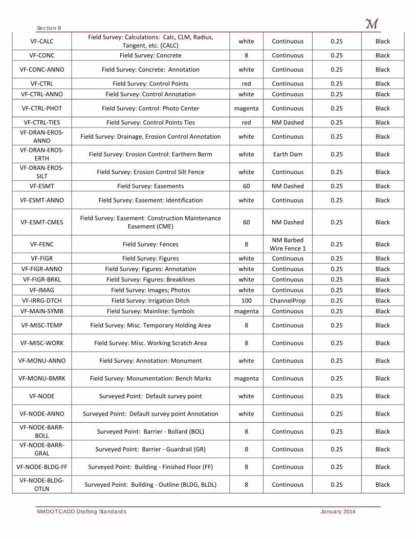
VF-CALC Field Survey: Calculations: Calc, CLM, Radius, Tangent, etc. (CALC) white Continuous 0.25 Black
VF-CONC Field Survey: Concrete 8 Continuous 0.25 Black
VF-CONC-ANNO Field Survey: Concrete: Annotation white Continuous 0.25 Black
VF-CTRL Field Survey: Control Points red Continuous 0.25 Black VF-CTRL-ANNO Field Survey: Control Annotation white Continuous 0.25 Black
VF-CTRL-PHOT Field Survey: Control: Photo Center magenta Continuous 0.25 Black
VF-CTRL-TIES Field Survey: Control Points Ties red NM Dashed 0.25 Black VF-DRAN-EROS-
ANNO Field Survey: Drainage, Erosion Control Annotation white Continuous 0.25 Black
VF-DRAN-EROS-ERTH Field Survey: Erosion Control: Earthern Berm white Earth Dam 0.25 Black
VF-DRAN-EROS-SILT Field Survey: Erosion Control Silt Fence white Continuous 0.25 Black
VF-ESMT Field Survey: Easements 60 NM Dashed 0.25 Black
VF-ESMT-ANNO Field Survey: Easement: Identification white Continuous 0.25 Black
VF-ESMT-CMES Field Survey: Easement: Construction Maintenance Easement (CME) 60 NM Dashed 0.25 Black
VF-FENC Field Survey: Fences 8 NM Barbed Wire Fence 1 0.25 Black
VF-FIGR Field Survey: Figures white Continuous 0.25 Black VF-FIGR-ANNO Field Survey: Figures: Annotation white Continuous 0.25 Black VF-FIGR-BRKL Field Survey: Figures: Breaklines white Continuous 0.25 Black
VF-IMAG Field Survey: Images; Photos white Continuous 0.25 Black VF-IRRG-DTCH Field Survey: Irrigation Ditch 100 ChannelProp 0.25 Black
VF-MAIN-SYMB Field Survey: Mainline: Symbols magenta Continuous 0.25 Black
VF-MISC-TEMP Field Survey: Misc. Temporary Holding Area 8 Continuous 0.25 Black
VF-MISC-WORK Field Survey: Misc. Working Scratch Area 8 Continuous 0.25 Black
VF-MONU-ANNO Field Survey: Annotation: Monument white Continuous 0.25 Black
VF-MONU-BMRK Field Survey: Monumentation: Bench Marks magenta Continuous 0.25 Black
VF-NODE Surveyed Point: Default survey point white Continuous 0.25 Black
VF-NODE-ANNO Surveyed Point: Default survey point Annotation white Continuous 0.25 Black
VF-NODE-BARR-BOLL Surveyed Point: Barrier - Bollard (BOL) 8 Continuous 0.25 Black
VF-NODE-BARR-GRAL Surveyed Point: Barrier - Guardrail (GR) 8 Continuous 0.25 Black
VF-NODE-BLDG-FF Surveyed Point: Building - Finished Floor (FF) 8 Continuous 0.25 Black
VF-NODE-BLDG-OTLN Surveyed Point: Building - Outline (BLDG, BLDL) 8 Continuous 0.25 Black
Section 8
January 2014 NMDOT CADD Drafting Standards
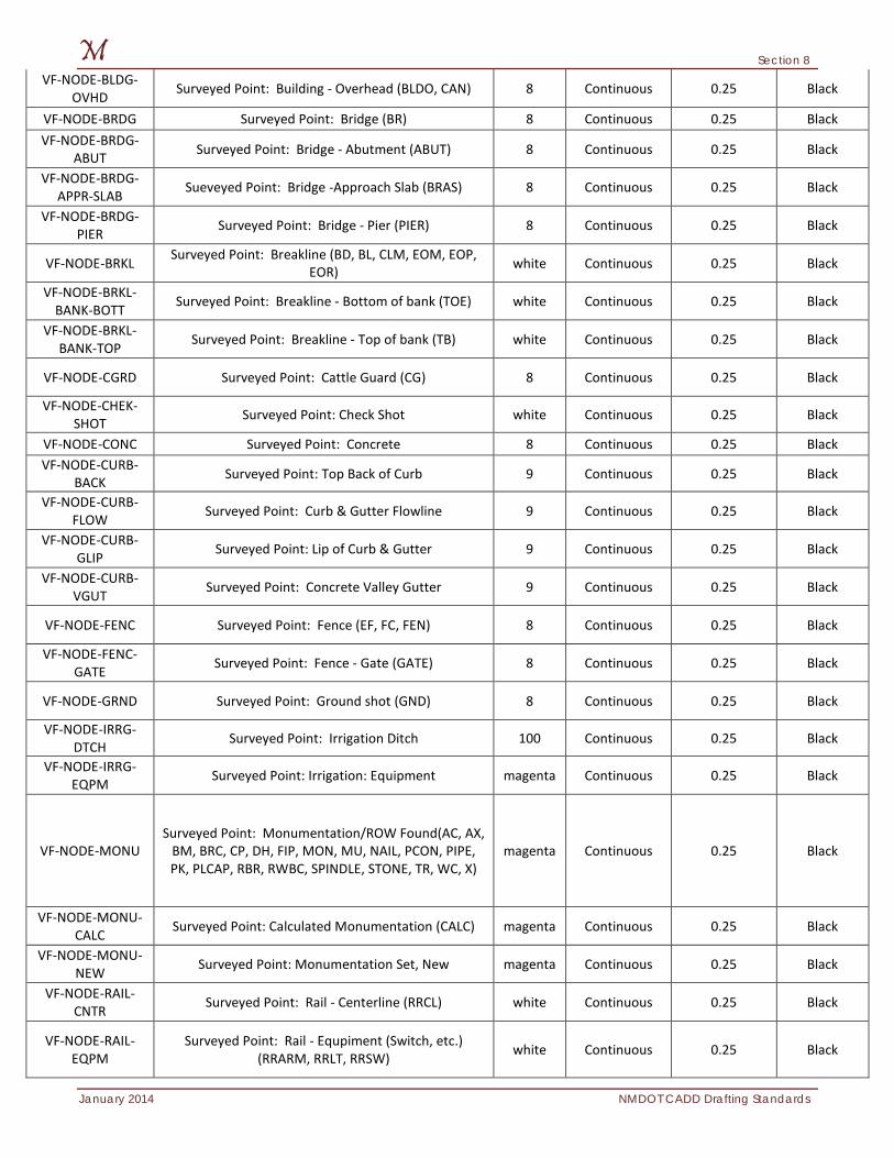
VF-NODE-BLDG-OVHD Surveyed Point: Building - Overhead (BLDO, CAN) 8 Continuous 0.25 Black
VF-NODE-BRDG Surveyed Point: Bridge (BR) 8 Continuous 0.25 Black VF-NODE-BRDG-
ABUT Surveyed Point: Bridge - Abutment (ABUT) 8 Continuous 0.25 Black
VF-NODE-BRDG-APPR-SLAB Sueveyed Point: Bridge -Approach Slab (BRAS) 8 Continuous 0.25 Black
VF-NODE-BRDG-PIER Surveyed Point: Bridge - Pier (PIER) 8 Continuous 0.25 Black
VF-NODE-BRKL Surveyed Point: Breakline (BD, BL, CLM, EOM, EOP, EOR) white Continuous 0.25 Black
VF-NODE-BRKL-BANK-BOTT Surveyed Point: Breakline - Bottom of bank (TOE) white Continuous 0.25 Black
VF-NODE-BRKL-BANK-TOP Surveyed Point: Breakline - Top of bank (TB) white Continuous 0.25 Black
VF-NODE-CGRD Surveyed Point: Cattle Guard (CG) 8 Continuous 0.25 Black
VF-NODE-CHEK-SHOT Surveyed Point: Check Shot white Continuous 0.25 Black
VF-NODE-CONC Surveyed Point: Concrete 8 Continuous 0.25 Black VF-NODE-CURB-
BACK Surveyed Point: Top Back of Curb 9 Continuous 0.25 Black
VF-NODE-CURB-FLOW Surveyed Point: Curb & Gutter Flowline 9 Continuous 0.25 Black
VF-NODE-CURB-GLIP Surveyed Point: Lip of Curb & Gutter 9 Continuous 0.25 Black
VF-NODE-CURB-VGUT Surveyed Point: Concrete Valley Gutter 9 Continuous 0.25 Black
VF-NODE-FENC Surveyed Point: Fence (EF, FC, FEN) 8 Continuous 0.25 Black
VF-NODE-FENC-GATE Surveyed Point: Fence - Gate (GATE) 8 Continuous 0.25 Black
VF-NODE-GRND Surveyed Point: Ground shot (GND) 8 Continuous 0.25 Black
VF-NODE-IRRG-DTCH Surveyed Point: Irrigation Ditch 100 Continuous 0.25 Black
VF-NODE-IRRG-EQPM Surveyed Point: Irrigation: Equipment magenta Continuous 0.25 Black
VF-NODE-MONU Surveyed Point: Monumentation/ROW Found(AC, AX,
BM, BRC, CP, DH, FIP, MON, MU, NAIL, PCON, PIPE, PK, PLCAP, RBR, RWBC, SPINDLE, STONE, TR, WC, X)
magenta Continuous 0.25 Black
VF-NODE-MONU-CALC Surveyed Point: Calculated Monumentation (CALC) magenta Continuous 0.25 Black
VF-NODE-MONU-NEW Surveyed Point: Monumentation Set, New magenta Continuous 0.25 Black
VF-NODE-RAIL-CNTR Surveyed Point: Rail - Centerline (RRCL) white Continuous 0.25 Black
VF-NODE-RAIL-EQPM
Surveyed Point: Rail - Equpiment (Switch, etc.) (RRARM, RRLT, RRSW) white Continuous 0.25 Black
Section 8
NMDOT CADD Drafting Standards January 2014
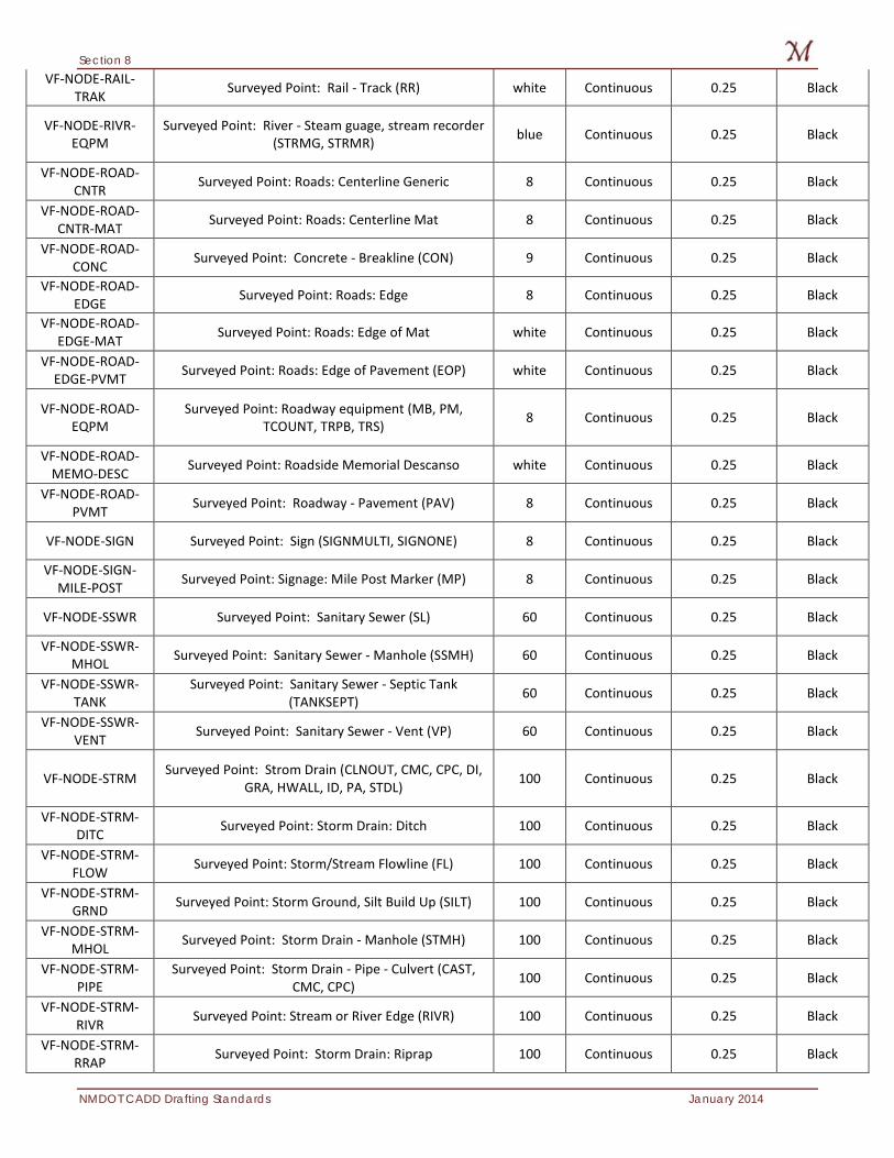
VF-NODE-RAIL-TRAK Surveyed Point: Rail - Track (RR) white Continuous 0.25 Black
VF-NODE-RIVR-EQPM
Surveyed Point: River - Steam guage, stream recorder (STRMG, STRMR) blue Continuous 0.25 Black
VF-NODE-ROAD-CNTR Surveyed Point: Roads: Centerline Generic 8 Continuous 0.25 Black
VF-NODE-ROAD-CNTR-MAT Surveyed Point: Roads: Centerline Mat 8 Continuous 0.25 Black
VF-NODE-ROAD-CONC Surveyed Point: Concrete - Breakline (CON) 9 Continuous 0.25 Black
VF-NODE-ROAD-EDGE Surveyed Point: Roads: Edge 8 Continuous 0.25 Black
VF-NODE-ROAD-EDGE-MAT Surveyed Point: Roads: Edge of Mat white Continuous 0.25 Black
VF-NODE-ROAD-EDGE-PVMT Surveyed Point: Roads: Edge of Pavement (EOP) white Continuous 0.25 Black
VF-NODE-ROAD-EQPM
Surveyed Point: Roadway equipment (MB, PM, TCOUNT, TRPB, TRS) 8 Continuous 0.25 Black
VF-NODE-ROAD-MEMO-DESC Surveyed Point: Roadside Memorial Descanso white Continuous 0.25 Black
VF-NODE-ROAD-PVMT Surveyed Point: Roadway - Pavement (PAV) 8 Continuous 0.25 Black
VF-NODE-SIGN Surveyed Point: Sign (SIGNMULTI, SIGNONE) 8 Continuous 0.25 Black
VF-NODE-SIGN-MILE-POST Surveyed Point: Signage: Mile Post Marker (MP) 8 Continuous 0.25 Black
VF-NODE-SSWR Surveyed Point: Sanitary Sewer (SL) 60 Continuous 0.25 Black
VF-NODE-SSWR-MHOL Surveyed Point: Sanitary Sewer - Manhole (SSMH) 60 Continuous 0.25 Black
VF-NODE-SSWR-TANK
Surveyed Point: Sanitary Sewer - Septic Tank (TANKSEPT) 60 Continuous 0.25 Black
VF-NODE-SSWR-VENT Surveyed Point: Sanitary Sewer - Vent (VP) 60 Continuous 0.25 Black
VF-NODE-STRM Surveyed Point: Strom Drain (CLNOUT, CMC, CPC, DI, GRA, HWALL, ID, PA, STDL) 100 Continuous 0.25 Black
VF-NODE-STRM-DITC Surveyed Point: Storm Drain: Ditch 100 Continuous 0.25 Black
VF-NODE-STRM-FLOW Surveyed Point: Storm/Stream Flowline (FL) 100 Continuous 0.25 Black
VF-NODE-STRM-GRND Surveyed Point: Storm Ground, Silt Build Up (SILT) 100 Continuous 0.25 Black
VF-NODE-STRM-MHOL Surveyed Point: Storm Drain - Manhole (STMH) 100 Continuous 0.25 Black
VF-NODE-STRM-PIPE
Surveyed Point: Storm Drain - Pipe - Culvert (CAST, CMC, CPC) 100 Continuous 0.25 Black
VF-NODE-STRM-RIVR Surveyed Point: Stream or River Edge (RIVR) 100 Continuous 0.25 Black
VF-NODE-STRM-RRAP Surveyed Point: Storm Drain: Riprap 100 Continuous 0.25 Black
Section 8
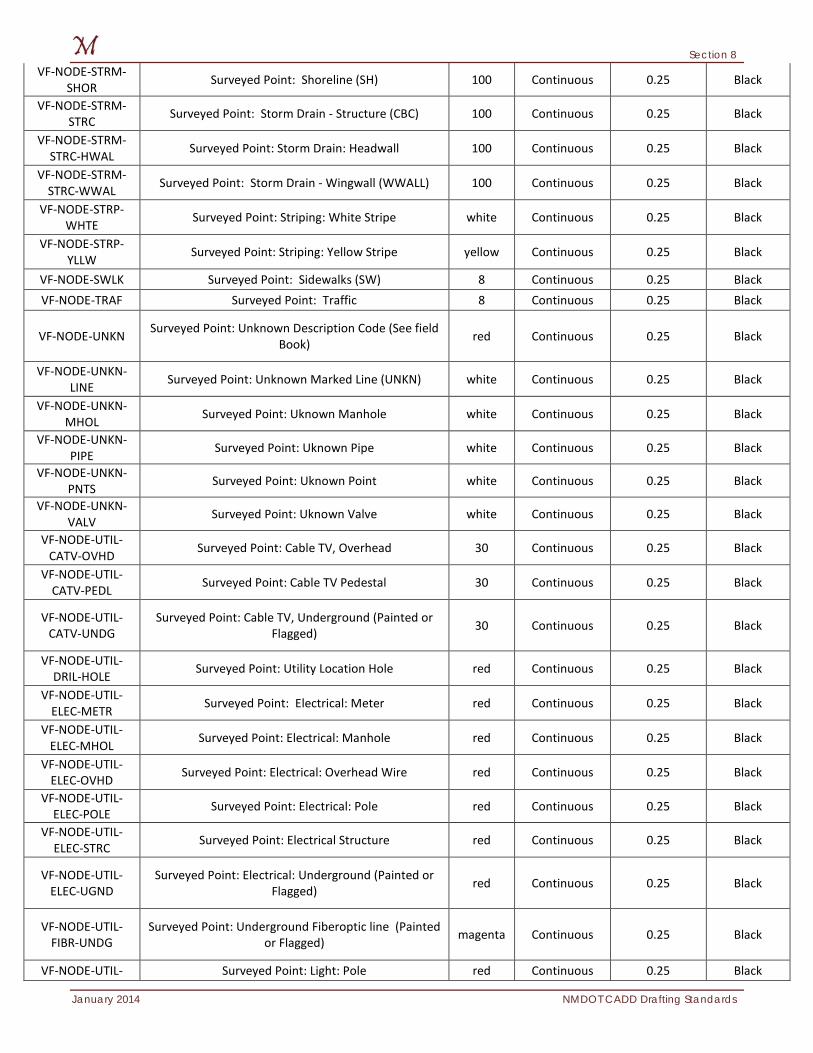
January 2014 NMDOT CADD Drafting Standards
VF-NODE-STRM-SHOR Surveyed Point: Shoreline (SH) 100 Continuous 0.25 Black
VF-NODE-STRM-STRC Surveyed Point: Storm Drain - Structure (CBC) 100 Continuous 0.25 Black
VF-NODE-STRM-STRC-HWAL Surveyed Point: Storm Drain: Headwall 100 Continuous 0.25 Black
VF-NODE-STRM-STRC-WWAL Surveyed Point: Storm Drain - Wingwall (WWALL) 100 Continuous 0.25 Black
VF-NODE-STRP-WHTE Surveyed Point: Striping: White Stripe white Continuous 0.25 Black
VF-NODE-STRP-YLLW Surveyed Point: Striping: Yellow Stripe yellow Continuous 0.25 Black
VF-NODE-SWLK Surveyed Point: Sidewalks (SW) 8 Continuous 0.25 Black VF-NODE-TRAF Surveyed Point: Traffic 8 Continuous 0.25 Black
VF-NODE-UNKN Surveyed Point: Unknown Description Code (See field Book) red Continuous 0.25 Black
VF-NODE-UNKN-LINE Surveyed Point: Unknown Marked Line (UNKN) white Continuous 0.25 Black
VF-NODE-UNKN-MHOL Surveyed Point: Uknown Manhole white Continuous 0.25 Black
VF-NODE-UNKN-PIPE Surveyed Point: Uknown Pipe white Continuous 0.25 Black
VF-NODE-UNKN-PNTS Surveyed Point: Uknown Point white Continuous 0.25 Black
VF-NODE-UNKN-VALV Surveyed Point: Uknown Valve white Continuous 0.25 Black
VF-NODE-UTIL-CATV-OVHD Surveyed Point: Cable TV, Overhead 30 Continuous 0.25 Black
VF-NODE-UTIL-CATV-PEDL Surveyed Point: Cable TV Pedestal 30 Continuous 0.25 Black
VF-NODE-UTIL-CATV-UNDG
Surveyed Point: Cable TV, Underground (Painted or Flagged) 30 Continuous 0.25 Black
VF-NODE-UTIL-DRIL-HOLE Surveyed Point: Utility Location Hole red Continuous 0.25 Black
VF-NODE-UTIL-ELEC-METR Surveyed Point: Electrical: Meter red Continuous 0.25 Black
VF-NODE-UTIL-ELEC-MHOL Surveyed Point: Electrical: Manhole red Continuous 0.25 Black
VF-NODE-UTIL-ELEC-OVHD Surveyed Point: Electrical: Overhead Wire red Continuous 0.25 Black
VF-NODE-UTIL-ELEC-POLE Surveyed Point: Electrical: Pole red Continuous 0.25 Black
VF-NODE-UTIL-ELEC-STRC Surveyed Point: Electrical Structure red Continuous 0.25 Black
VF-NODE-UTIL-ELEC-UGND
Surveyed Point: Electrical: Underground (Painted or Flagged) red Continuous 0.25 Black
VF-NODE-UTIL-FIBR-UNDG
Surveyed Point: Underground Fiberoptic line (Painted or Flagged) magenta Continuous 0.25 Black
VF-NODE-UTIL- Surveyed Point: Light: Pole red Continuous 0.25 Black
Section 8
NMDOT CADD Drafting Standards January 2014
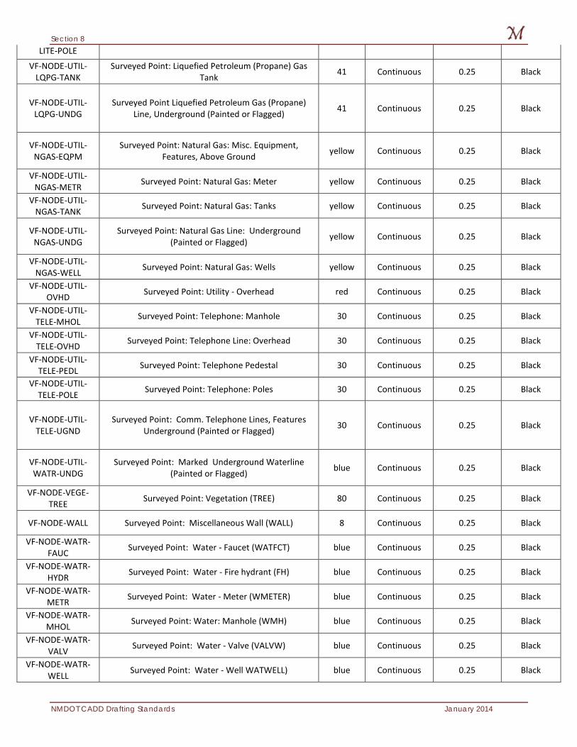
LITE-POLE
VF-NODE-UTIL-LQPG-TANK
Surveyed Point: Liquefied Petroleum (Propane) Gas Tank 41 Continuous 0.25 Black
VF-NODE-UTIL-LQPG-UNDG
Surveyed Point Liquefied Petroleum Gas (Propane) Line, Underground (Painted or Flagged) 41 Continuous 0.25 Black
VF-NODE-UTIL-NGAS-EQPM
Surveyed Point: Natural Gas: Misc. Equipment, Features, Above Ground yellow Continuous 0.25 Black
VF-NODE-UTIL-NGAS-METR Surveyed Point: Natural Gas: Meter yellow Continuous 0.25 Black
VF-NODE-UTIL-NGAS-TANK Surveyed Point: Natural Gas: Tanks yellow Continuous 0.25 Black
VF-NODE-UTIL-NGAS-UNDG
Surveyed Point: Natural Gas Line: Underground (Painted or Flagged) yellow Continuous 0.25 Black
VF-NODE-UTIL-NGAS-WELL Surveyed Point: Natural Gas: Wells yellow Continuous 0.25 Black
VF-NODE-UTIL-OVHD Surveyed Point: Utility - Overhead red Continuous 0.25 Black
VF-NODE-UTIL-TELE-MHOL Surveyed Point: Telephone: Manhole 30 Continuous 0.25 Black
VF-NODE-UTIL-TELE-OVHD Surveyed Point: Telephone Line: Overhead 30 Continuous 0.25 Black
VF-NODE-UTIL-TELE-PEDL Surveyed Point: Telephone Pedestal 30 Continuous 0.25 Black
VF-NODE-UTIL-TELE-POLE Surveyed Point: Telephone: Poles 30 Continuous 0.25 Black
VF-NODE-UTIL-TELE-UGND
Surveyed Point: Comm. Telephone Lines, Features Underground (Painted or Flagged) 30 Continuous 0.25 Black
VF-NODE-UTIL-WATR-UNDG
Surveyed Point: Marked Underground Waterline (Painted or Flagged) blue Continuous 0.25 Black
VF-NODE-VEGE-TREE Surveyed Point: Vegetation (TREE) 80 Continuous 0.25 Black
VF-NODE-WALL Surveyed Point: Miscellaneous Wall (WALL) 8 Continuous 0.25 Black
VF-NODE-WATR-FAUC Surveyed Point: Water - Faucet (WATFCT) blue Continuous 0.25 Black
VF-NODE-WATR-HYDR Surveyed Point: Water - Fire hydrant (FH) blue Continuous 0.25 Black
VF-NODE-WATR-METR Surveyed Point: Water - Meter (WMETER) blue Continuous 0.25 Black
VF-NODE-WATR-MHOL Surveyed Point: Water: Manhole (WMH) blue Continuous 0.25 Black
VF-NODE-WATR-VALV Surveyed Point: Water - Valve (VALVW) blue Continuous 0.25 Black
VF-NODE-WATR-WELL Surveyed Point: Water - Well WATWELL) blue Continuous 0.25 Black
Section 8
January 2014 NMDOT CADD Drafting Standards
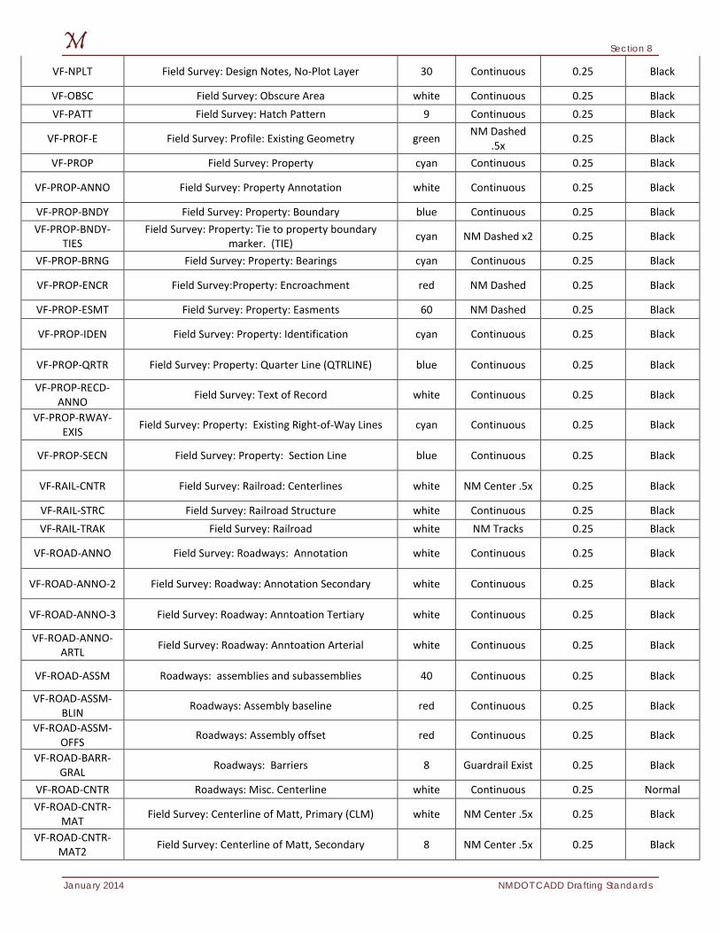
VF-NPLT Field Survey: Design Notes, No-Plot Layer 30 Continuous 0.25 Black
VF-OBSC Field Survey: Obscure Area white Continuous 0.25 Black VF-PATT Field Survey: Hatch Pattern 9 Continuous 0.25 Black
VF-PROF-E Field Survey: Profile: Existing Geometry green NM Dashed .5x 0.25 Black
VF-PROP Field Survey: Property cyan Continuous 0.25 Black
VF-PROP-ANNO Field Survey: Property Annotation white Continuous 0.25 Black
VF-PROP-BNDY Field Survey: Property: Boundary blue Continuous 0.25 Black VF-PROP-BNDY-
TIES Field Survey: Property: Tie to property boundary
marker. (TIE) cyan NM Dashed x2 0.25 Black
VF-PROP-BRNG Field Survey: Property: Bearings cyan Continuous 0.25 Black
VF-PROP-ENCR Field Survey:Property: Encroachment red NM Dashed 0.25 Black
VF-PROP-ESMT Field Survey: Property: Easments 60 NM Dashed 0.25 Black
VF-PROP-IDEN Field Survey: Property: Identification cyan Continuous 0.25 Black
VF-PROP-QRTR Field Survey: Property: Quarter Line (QTRLINE) blue Continuous 0.25 Black
VF-PROP-RECD-ANNO Field Survey: Text of Record white Continuous 0.25 Black
VF-PROP-RWAY-EXIS Field Survey: Property: Existing Right-of-Way Lines cyan Continuous 0.25 Black
VF-PROP-SECN Field Survey: Property: Section Line blue Continuous 0.25 Black
VF-RAIL-CNTR Field Survey: Railroad: Centerlines white NM Center .5x 0.25 Black
VF-RAIL-STRC Field Survey: Railroad Structure white Continuous 0.25 Black VF-RAIL-TRAK Field Survey: Railroad white NM Tracks 0.25 Black
VF-ROAD-ANNO Field Survey: Roadways: Annotation white Continuous 0.25 Black
VF-ROAD-ANNO-2 Field Survey: Roadway: Annotation Secondary white Continuous 0.25 Black
VF-ROAD-ANNO-3 Field Survey: Roadway: Anntoation Tertiary white Continuous 0.25 Black
VF-ROAD-ANNO-ARTL Field Survey: Roadway: Anntoation Arterial white Continuous 0.25 Black
VF-ROAD-ASSM Roadways: assemblies and subassemblies 40 Continuous 0.25 Black
VF-ROAD-ASSM-BLIN Roadways: Assembly baseline red Continuous 0.25 Black
VF-ROAD-ASSM-OFFS Roadways: Assembly offset red Continuous 0.25 Black
VF-ROAD-BARR-GRAL Roadways: Barriers 8 Guardrail Exist 0.25 Black
VF-ROAD-CNTR Roadways: Misc. Centerline white Continuous 0.25 Normal VF-ROAD-CNTR-
MAT Field Survey: Centerline of Matt, Primary (CLM) white NM Center .5x 0.25 Black
VF-ROAD-CNTR-MAT2 Field Survey: Centerline of Matt, Secondary 8 NM Center .5x 0.25 Black
Section 8
NMDOT CADD Drafting Standards January 2014
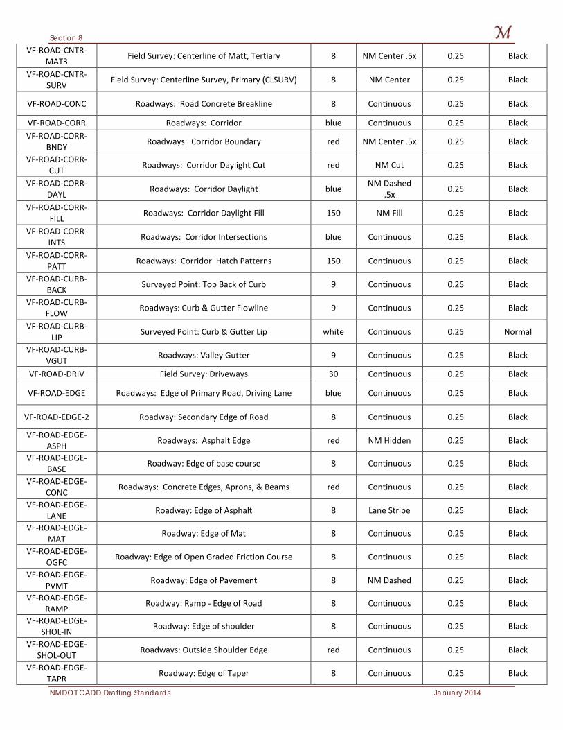
VF-ROAD-CNTR-MAT3 Field Survey: Centerline of Matt, Tertiary 8 NM Center .5x 0.25 Black
VF-ROAD-CNTR-SURV Field Survey: Centerline Survey, Primary (CLSURV) 8 NM Center 0.25 Black
VF-ROAD-CONC Roadways: Road Concrete Breakline 8 Continuous 0.25 Black
VF-ROAD-CORR Roadways: Corridor blue Continuous 0.25 Black VF-ROAD-CORR-
BNDY Roadways: Corridor Boundary red NM Center .5x 0.25 Black
VF-ROAD-CORR-CUT Roadways: Corridor Daylight Cut red NM Cut 0.25 Black
VF-ROAD-CORR-DAYL Roadways: Corridor Daylight blue NM Dashed
.5x 0.25 Black
VF-ROAD-CORR-FILL Roadways: Corridor Daylight Fill 150 NM Fill 0.25 Black
VF-ROAD-CORR-INTS Roadways: Corridor Intersections blue Continuous 0.25 Black
VF-ROAD-CORR-PATT Roadways: Corridor Hatch Patterns 150 Continuous 0.25 Black
VF-ROAD-CURB-BACK Surveyed Point: Top Back of Curb 9 Continuous 0.25 Black
VF-ROAD-CURB-FLOW Roadways: Curb & Gutter Flowline 9 Continuous 0.25 Black
VF-ROAD-CURB-LIP Surveyed Point: Curb & Gutter Lip white Continuous 0.25 Normal
VF-ROAD-CURB-VGUT Roadways: Valley Gutter 9 Continuous 0.25 Black
VF-ROAD-DRIV Field Survey: Driveways 30 Continuous 0.25 Black
VF-ROAD-EDGE Roadways: Edge of Primary Road, Driving Lane blue Continuous 0.25 Black
VF-ROAD-EDGE-2 Roadway: Secondary Edge of Road 8 Continuous 0.25 Black
VF-ROAD-EDGE-ASPH Roadways: Asphalt Edge red NM Hidden 0.25 Black
VF-ROAD-EDGE-BASE Roadway: Edge of base course 8 Continuous 0.25 Black
VF-ROAD-EDGE-CONC Roadways: Concrete Edges, Aprons, & Beams red Continuous 0.25 Black
VF-ROAD-EDGE-LANE Roadway: Edge of Asphalt 8 Lane Stripe 0.25 Black
VF-ROAD-EDGE-MAT Roadway: Edge of Mat 8 Continuous 0.25 Black
VF-ROAD-EDGE-OGFC Roadway: Edge of Open Graded Friction Course 8 Continuous 0.25 Black
VF-ROAD-EDGE-PVMT Roadway: Edge of Pavement 8 NM Dashed 0.25 Black
VF-ROAD-EDGE-RAMP Roadway: Ramp - Edge of Road 8 Continuous 0.25 Black
VF-ROAD-EDGE-SHOL-IN Roadway: Edge of shoulder 8 Continuous 0.25 Black
VF-ROAD-EDGE-SHOL-OUT Roadways: Outside Shoulder Edge red Continuous 0.25 Black
VF-ROAD-EDGE-TAPR Roadway: Edge of Taper 8 Continuous 0.25 Black
Section 8
January 2014 NMDOT CADD Drafting Standards
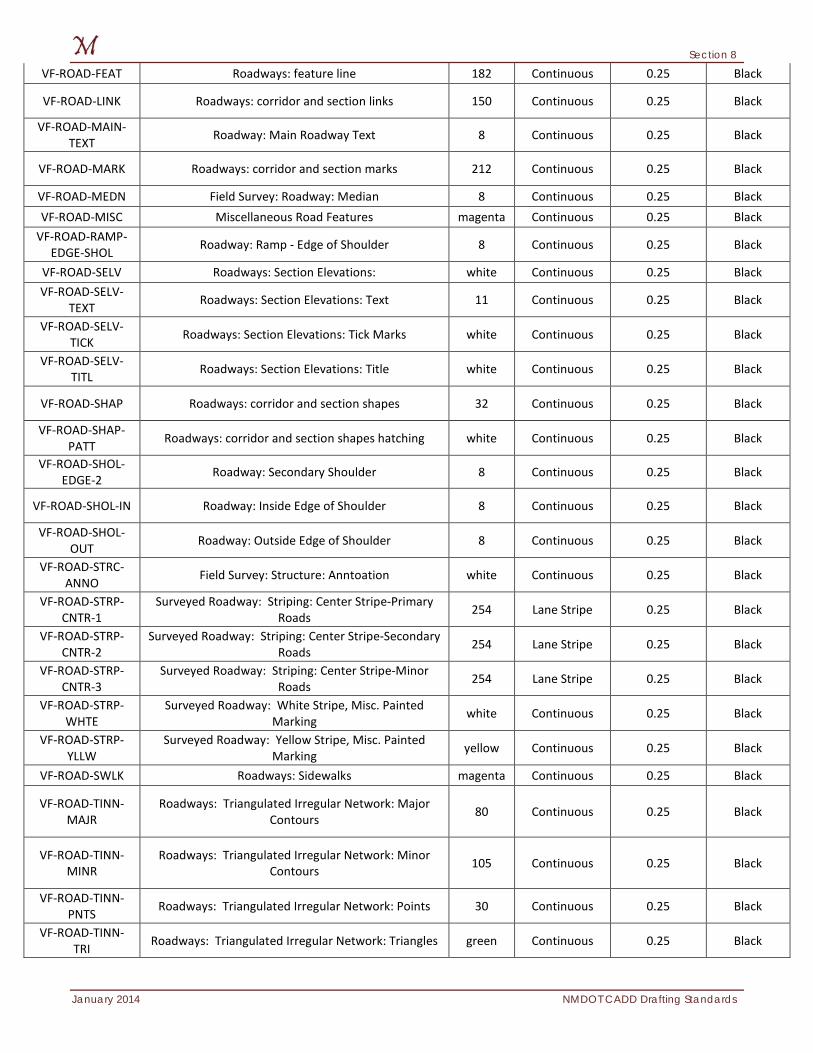
VF-ROAD-FEAT Roadways: feature line 182 Continuous 0.25 Black
VF-ROAD-LINK Roadways: corridor and section links 150 Continuous 0.25 Black
VF-ROAD-MAIN-TEXT Roadway: Main Roadway Text 8 Continuous 0.25 Black
VF-ROAD-MARK Roadways: corridor and section marks 212 Continuous 0.25 Black
VF-ROAD-MEDN Field Survey: Roadway: Median 8 Continuous 0.25 Black VF-ROAD-MISC Miscellaneous Road Features magenta Continuous 0.25 Black
VF-ROAD-RAMP-EDGE-SHOL Roadway: Ramp - Edge of Shoulder 8 Continuous 0.25 Black
VF-ROAD-SELV Roadways: Section Elevations: white Continuous 0.25 Black VF-ROAD-SELV-
TEXT Roadways: Section Elevations: Text 11 Continuous 0.25 Black
VF-ROAD-SELV-TICK Roadways: Section Elevations: Tick Marks white Continuous 0.25 Black
VF-ROAD-SELV-TITL Roadways: Section Elevations: Title white Continuous 0.25 Black
VF-ROAD-SHAP Roadways: corridor and section shapes 32 Continuous 0.25 Black
VF-ROAD-SHAP-PATT Roadways: corridor and section shapes hatching white Continuous 0.25 Black
VF-ROAD-SHOL-EDGE-2 Roadway: Secondary Shoulder 8 Continuous 0.25 Black
VF-ROAD-SHOL-IN Roadway: Inside Edge of Shoulder 8 Continuous 0.25 Black
VF-ROAD-SHOL-OUT Roadway: Outside Edge of Shoulder 8 Continuous 0.25 Black
VF-ROAD-STRC-ANNO Field Survey: Structure: Anntoation white Continuous 0.25 Black
VF-ROAD-STRP-CNTR-1
Surveyed Roadway: Striping: Center Stripe-Primary Roads 254 Lane Stripe 0.25 Black
VF-ROAD-STRP-CNTR-2
Surveyed Roadway: Striping: Center Stripe-Secondary Roads 254 Lane Stripe 0.25 Black
VF-ROAD-STRP-CNTR-3
Surveyed Roadway: Striping: Center Stripe-Minor Roads 254 Lane Stripe 0.25 Black
VF-ROAD-STRP-WHTE
Surveyed Roadway: White Stripe, Misc. Painted Marking white Continuous 0.25 Black
VF-ROAD-STRP-YLLW
Surveyed Roadway: Yellow Stripe, Misc. Painted Marking yellow Continuous 0.25 Black
VF-ROAD-SWLK Roadways: Sidewalks magenta Continuous 0.25 Black
VF-ROAD-TINN-MAJR
Roadways: Triangulated Irregular Network: Major Contours 80 Continuous 0.25 Black
VF-ROAD-TINN-MINR
Roadways: Triangulated Irregular Network: Minor Contours 105 Continuous 0.25 Black
VF-ROAD-TINN-PNTS Roadways: Triangulated Irregular Network: Points 30 Continuous 0.25 Black
VF-ROAD-TINN-TRI Roadways: Triangulated Irregular Network: Triangles green Continuous 0.25 Black
Section 8
NMDOT CADD Drafting Standards January 2014
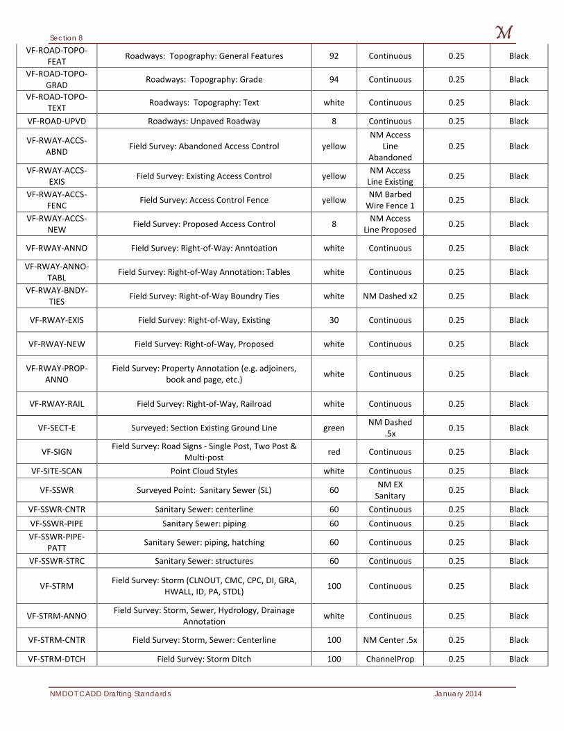
VF-ROAD-TOPO-FEAT Roadways: Topography: General Features 92 Continuous 0.25 Black
VF-ROAD-TOPO-GRAD Roadways: Topography: Grade 94 Continuous 0.25 Black
VF-ROAD-TOPO-TEXT Roadways: Topography: Text white Continuous 0.25 Black
VF-ROAD-UPVD Roadways: Unpaved Roadway 8 Continuous 0.25 Black
VF-RWAY-ACCS-ABND Field Survey: Abandoned Access Control yellow
NM Access Line
Abandoned 0.25 Black
VF-RWAY-ACCS-EXIS Field Survey: Existing Access Control yellow NM Access
Line Existing 0.25 Black
VF-RWAY-ACCS-FENC Field Survey: Access Control Fence yellow NM Barbed
Wire Fence 1 0.25 Black
VF-RWAY-ACCS-NEW Field Survey: Proposed Access Control 8 NM Access
Line Proposed 0.25 Black
VF-RWAY-ANNO Field Survey: Right-of-Way: Anntoation white Continuous 0.25 Black
VF-RWAY-ANNO-TABL Field Survey: Right-of-Way Annotation: Tables white Continuous 0.25 Black
VF-RWAY-BNDY-TIES Field Survey: Right-of-Way Boundry Ties white NM Dashed x2 0.25 Black
VF-RWAY-EXIS Field Survey: Right-of-Way, Existing 30 Continuous 0.25 Black
VF-RWAY-NEW Field Survey: Right-of-Way, Proposed white Continuous 0.25 Black
VF-RWAY-PROP-ANNO
Field Survey: Property Annotation (e.g. adjoiners, book and page, etc.) white Continuous 0.25 Black
VF-RWAY-RAIL Field Survey: Right-of-Way, Railroad white Continuous 0.25 Black
VF-SECT-E Surveyed: Section Existing Ground Line green NM Dashed .5x 0.15 Black
VF-SIGN Field Survey: Road Signs - Single Post, Two Post & Multi-post red Continuous 0.25 Black
VF-SITE-SCAN Point Cloud Styles white Continuous 0.25 Black
VF-SSWR Surveyed Point: Sanitary Sewer (SL) 60 NM EX Sanitary 0.25 Black
VF-SSWR-CNTR Sanitary Sewer: centerline 60 Continuous 0.25 Black VF-SSWR-PIPE Sanitary Sewer: piping 60 Continuous 0.25 Black VF-SSWR-PIPE-
PATT Sanitary Sewer: piping, hatching 60 Continuous 0.25 Black
VF-SSWR-STRC Sanitary Sewer: structures 60 Continuous 0.25 Black
VF-STRM Field Survey: Storm (CLNOUT, CMC, CPC, DI, GRA, HWALL, ID, PA, STDL) 100 Continuous 0.25 Black
VF-STRM-ANNO Field Survey: Storm, Sewer, Hydrology, Drainage Annotation white Continuous 0.25 Black
VF-STRM-CNTR Field Survey: Storm, Sewer: Centerline 100 NM Center .5x 0.25 Black
VF-STRM-DTCH Field Survey: Storm Ditch 100 ChannelProp 0.25 Black
Section 8
January 2014 NMDOT CADD Drafting Standards
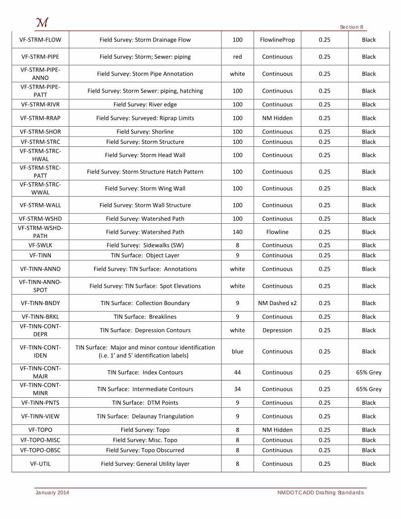
VF-STRM-FLOW Field Survey: Storm Drainage Flow 100 FlowlineProp 0.25 Black
VF-STRM-PIPE Field Survey: Storm; Sewer: piping red Continuous 0.25 Black
VF-STRM-PIPE-ANNO Field Survey: Storm Pipe Annotation white Continuous 0.25 Black
VF-STRM-PIPE-PATT Field Survey: Storm Sewer: piping, hatching 100 Continuous 0.25 Black
VF-STRM-RIVR Field Survey: River edge 100 Continuous 0.25 Black
VF-STRM-RRAP Field Survey: Surveyed: Riprap Limits 100 NM Hidden 0.25 Black
VF-STRM-SHOR Field Survey: Shorline 100 Continuous 0.25 Black VF-STRM-STRC Field Survey: Storm Structure 100 Continuous 0.25 Black VF-STRM-STRC-
HWAL Field Survey: Storm Head Wall 100 Continuous 0.25 Black
VF-STRM-STRC-PATT Field Survey: Storm Structure Hatch Pattern 100 Continuous 0.25 Black
VF-STRM-STRC-WWAL Field Survey: Storm Wing Wall 100 Continuous 0.25 Black
VF-STRM-WALL Field Survey: Storm Wall Structure 100 Continuous 0.25 Black
VF-STRM-WSHD Field Survey: Watershed Path 100 Continuous 0.25 Black VF-STRM-WSHD-
PATH Field Survey: Watershed Path 140 Flowline 0.25 Black
VF-SWLK Field Survey: Sidewalks (SW) 8 Continuous 0.25 Black VF-TINN TIN Surface: Object Layer 9 Continuous 0.25 Black
VF-TINN-ANNO Field Survey: TIN Surface: Annotations white Continuous 0.25 Black
VF-TINN-ANNO-SPOT Field Survey: TIN Surface: Spot Elevations white Continuous 0.25 Black
VF-TINN-BNDY TIN Surface: Collection Boundary 9 NM Dashed x2 0.25 Black
VF-TINN-BRKL TIN Surface: Breaklines 9 Continuous 0.25 Black VF-TINN-CONT-
DEPR TIN Surface: Depression Contours white Depression 0.25 Black
VF-TINN-CONT-IDEN
TIN Surface: Major and minor contour identification (i.e. 1' and 5' identification labels) blue Continuous 0.25 Black
VF-TINN-CONT-MAJR TIN Surface: Index Contours 44 Continuous 0.25 65% Grey
VF-TINN-CONT-MINR TIN Surface: Intermediate Contours 34 Continuous 0.25 65% Grey
VF-TINN-PNTS TIN Surface: DTM Points 9 Continuous 0.25 Black
VF-TINN-VIEW TIN Surface: Delaunay Triangulation 9 Continuous 0.25 Black
VF-TOPO Field Survey: Topo 8 NM Hidden 0.25 Black VF-TOPO-MISC Field Survey: Misc. Topo 8 Continuous 0.25 Black VF-TOPO-OBSC Field Survey: Topo Obscurred 8 Continuous 0.25 Black
VF-UTIL Field Survey: General Utility layer 8 Continuous 0.25 Black
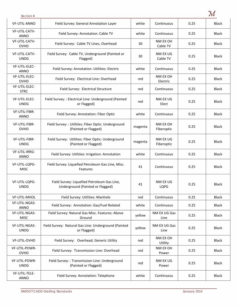
Section 8
NMDOT CADD Drafting Standards January 2014
VF-UTIL-ANNO Field Survey: General Annotation Layer white Continuous 0.25 Black
VF-UTIL-CATV-ANNO Field Survey: Annotation: Cable TV white Continuous 0.25 Black
VF-UTIL-CATV-OVHD Field Survey: Cable TV Lines, Overhead 30 NM EX OH
Cable TV 0.25 Black
VF-UTIL-CATV-UNDG
Field Survey: Cable TV, Underground (Painted or Flagged) 30 NM EX UG
Cable TV 0.25 Black
VF-UTIL-ELEC-ANNO Field Survey: Annotation: Utilities: Electric white Continuous 0.25 Black
VF-UTIL-ELEC-OVHD Field Survey: Electrical Line: Overhead red NM EX OH
Electric 0.25 Black
VF-UTIL-ELEC-STRC Field Survey: Electrical Structure red Continuous 0.25 Black
VF-UTIL-ELEC-UNDG
Field Survey: : Electrical Line: Underground (Painted or Flagged) red NM EX UG
Elect 0.25 Black
VF-UTIL-FIBR-ANNO Field Survey: Annotation: Fiber Optic white Continuous 0.25 Black
VF-UTIL-FIBR-OVHD
Field Survey: : Utilities: Fiber Optic: Underground (Painted or Flagged) magenta NM EX OH
Fiberoptic 0.25 Black
VF-UTIL-FIBR-UNDG
Field Survey: Utilities: Fiber Optic: Underground (Painted or Flagged) magenta NM EX UG
Fiberoptic 0.25 Black
VF-UTIL-IRRG-ANNO Field Survey: Utilities: Irrigation: Annotation white Continuous 0.25 Black
VF-UTIL-LQPG-MISC
Field Survey: Liquefied Petroleum Gas Line, Misc. Features 41 Continuous 0.25 Black
VF-UTIL-LQPG-UNDG
Field Survey: Liquefied Petroleum Gas Line, Underground (Painted or Flagged) 41 NM EX UG
LQPG 0.25 Black
VF-UTIL-MHOL Field Survey: Utilities: Manhole red Continuous 0.25 Black VF-UTIL-NGAS-
ANNO Field Survey: Annotation: Gas/Fuel Related white Continuous 0.25 Black
VF-UTIL-NGAS-MISC
Field Survey: Natural Gas Misc. Features: Above Ground yellow NM EX UG Gas
Line 0.25 Black
VF-UTIL-NGAS-UNDG
Field Survey: Natural Gas Line: Underground (Painted or Flagged) yellow NM EX UG Gas
Line 0.25 Black
VF-UTIL-OVHD Field Survey: Overhead, Generic Utility red NM EX OH Utility 0.25 Black
VF-UTIL-POWR-OVHD Field Survey: Transmission Line: Overhead red NM EX OH
Power 0.25 Black
VF-UTIL-POWR-UNDG
Field Survey: : Transmission Line: Underground (Painted or Flagged) red NM EX UG
Power 0.25 Black
VF-UTIL-TELE-ANNO Field Survey: Annotation: Telephone white Continuous 0.25 Black

Section 8
January 2014 NMDOT CADD Drafting Standards
VF-UTIL-TELE-OVHD Field Survey: Comm. Telephone Lines, Overhead 30 NM EX OH
Telephone 0.25 Black
VF-UTIL-TELE-UNDG
Field Survey: Comm. Telephone Lines, Features Underground (Painted or Flagged) 30 NM EX UG
Telephone 0.25 Black
VF-UTIL-UNKN Field Survey: Unknown Marked Line magenta NM EX Unknown Line 0.25 Black
VF-UTIL-UNKN-MHOL Field Survey: Unknown Manhole magenta Continuous 0.25 Black
VF-UTIL-WATR-ANNO Field Survey: General Annotation Layer white Continuous 0.25 Black
VF-UTIL-WATR-MISC Field Survey: : Water-Miscellaneous Features blue Continuous 0.25 Black
VF-UTIL-WATR-UNDG
Field Survey: : Marked Underground Waterline (Painted or Flagged) blue NM EX UG
Water Line 0.25 Black
VF-UTIL-WIRE-XING Field Survey: Wire Crossing magenta NM EX Wire
Crossing 0.25 Black
VF-VEGE-TREE Field Survey: Trees, Shrubs, etc. 80 Tree CW 0.25 Black
VF-WALL Field Survey: Wall, Miscellaneous 8 Continuous 0.25 Black
VF-XREF Attached External Drawing References white Continuous 0.25 Black
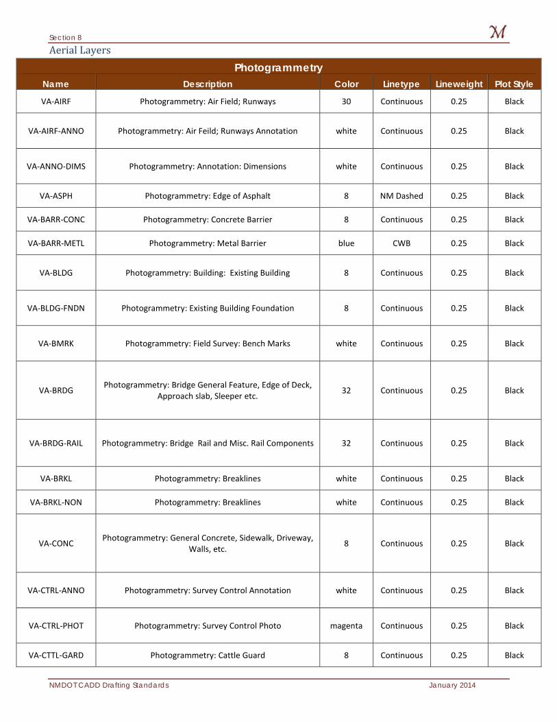
Section 8
NMDOT CADD Drafting Standards January 2014
Aerial Layers
Photogrammetry Name Description Color Linetype Lineweight Plot Style
VA-AIRF Photogrammetry: Air Field; Runways 30 Continuous 0.25 Black
VA-AIRF-ANNO Photogrammetry: Air Feild; Runways Annotation white Continuous 0.25 Black
VA-ANNO-DIMS Photogrammetry: Annotation: Dimensions white Continuous 0.25 Black
VA-ASPH Photogrammetry: Edge of Asphalt 8 NM Dashed 0.25 Black
VA-BARR-CONC Photogrammetry: Concrete Barrier 8 Continuous 0.25 Black
VA-BARR-METL Photogrammetry: Metal Barrier blue CWB 0.25 Black
VA-BLDG Photogrammetry: Building: Existing Building 8 Continuous 0.25 Black
VA-BLDG-FNDN Photogrammetry: Existing Building Foundation 8 Continuous 0.25 Black
VA-BMRK Photogrammetry: Field Survey: Bench Marks white Continuous 0.25 Black
VA-BRDG Photogrammetry: Bridge General Feature, Edge of Deck, Approach slab, Sleeper etc. 32 Continuous 0.25 Black
VA-BRDG-RAIL Photogrammetry: Bridge Rail and Misc. Rail Components 32 Continuous 0.25 Black
VA-BRKL Photogrammetry: Breaklines white Continuous 0.25 Black
VA-BRKL-NON Photogrammetry: Breaklines white Continuous 0.25 Black
VA-CONC Photogrammetry: General Concrete, Sidewalk, Driveway, Walls, etc. 8 Continuous 0.25 Black
VA-CTRL-ANNO Photogrammetry: Survey Control Annotation white Continuous 0.25 Black
VA-CTRL-PHOT Photogrammetry: Survey Control Photo magenta Continuous 0.25 Black
VA-CTTL-GARD Photogrammetry: Cattle Guard 8 Continuous 0.25 Black
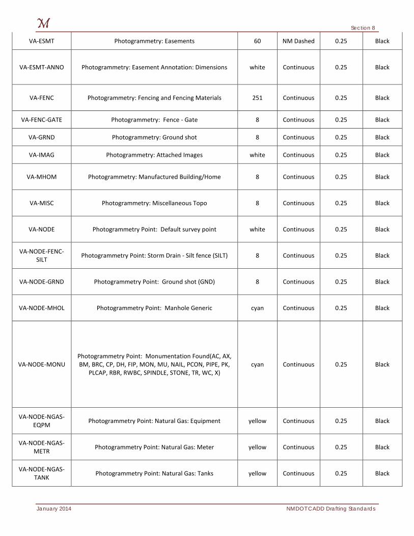
Section 8
January 2014 NMDOT CADD Drafting Standards
VA-ESMT Photogrammetry: Easements 60 NM Dashed 0.25 Black
VA-ESMT-ANNO Photogrammetry: Easement Annotation: Dimensions white Continuous 0.25 Black
VA-FENC Photogrammetry: Fencing and Fencing Materials 251 Continuous 0.25 Black
VA-FENC-GATE Photogrammetry: Fence - Gate 8 Continuous 0.25 Black
VA-GRND Photogrammetry: Ground shot 8 Continuous 0.25 Black
VA-IMAG Photogrammetry: Attached Images white Continuous 0.25 Black
VA-MHOM Photogrammetry: Manufactured Building/Home 8 Continuous 0.25 Black
VA-MISC Photogrammetry: Miscellaneous Topo 8 Continuous 0.25 Black
VA-NODE Photogrammetry Point: Default survey point white Continuous 0.25 Black
VA-NODE-FENC-SILT Photogrammetry Point: Storm Drain - Silt fence (SILT) 8 Continuous 0.25 Black
VA-NODE-GRND Photogrammetry Point: Ground shot (GND) 8 Continuous 0.25 Black
VA-NODE-MHOL Photogrammetry Point: Manhole Generic cyan Continuous 0.25 Black
VA-NODE-MONU Photogrammetry Point: Monumentation Found(AC, AX, BM, BRC, CP, DH, FIP, MON, MU, NAIL, PCON, PIPE, PK,
PLCAP, RBR, RWBC, SPINDLE, STONE, TR, WC, X) cyan Continuous 0.25 Black
VA-NODE-NGAS-EQPM Photogrammetry Point: Natural Gas: Equipment yellow Continuous 0.25 Black
VA-NODE-NGAS-METR Photogrammetry Point: Natural Gas: Meter yellow Continuous 0.25 Black
VA-NODE-NGAS-TANK Photogrammetry Point: Natural Gas: Tanks yellow Continuous 0.25 Black
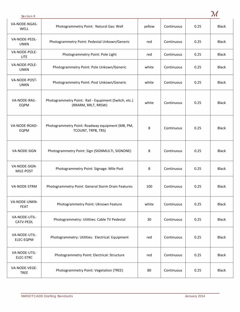
Section 8
NMDOT CADD Drafting Standards January 2014
VA-NODE-NGAS-WELL Photogrammetry Point: Natural Gas: Well yellow Continuous 0.25 Black
VA-NODE-PEDL-UNKN Photogrammetry Point: Pedestal Unkown/Generic red Continuous 0.25 Black
VA-NODE-POLE-LITE Photogrammetry Point: Pole Light red Continuous 0.25 Black
VA-NODE-POLE-UNKN Photogrammetry Point: Pole Unkown/Generic white Continuous 0.25 Black
VA-NODE-POST-UNKN Photogrammetry Point: Post Unkown/Generic white Continuous 0.25 Black
VA-NODE-RAIL-EQPM
Photogrammetry Point: Rail - Equpiment (Switch, etc.) (RRARM, RRLT, RRSW) white Continuous 0.25 Black
VA-NODE-ROAD-EQPM
Photogrammetry Point: Roadway equipment (MB, PM, TCOUNT, TRPB, TRS) 8 Continuous 0.25 Black
VA-NODE-SIGN Photogrammetry Point: Sign (SIGNMULTI, SIGNONE) 8 Continuous 0.25 Black
VA-NODE-SIGN-MILE-POST Photogrammetry Point: Signage: Mile Post 8 Continuous 0.25 Black
VA-NODE-STRM Photogrammetry Point: General Storm Drain Features 100 Continuous 0.25 Black
VA-NODE-UNKN-FEAT Photogrammetry Point: Uknown Feature white Continuous 0.25 Black
VA-NODE-UTIL-CATV-PEDL Photogrammetry: Utilities: Cable TV Pedestal 30 Continuous 0.25 Black
VA-NODE-UTIL-ELEC-EQPM Photogrammetry: Utilities: Electrical: Equipment red Continuous 0.25 Black
VA-NODE-UTIL-ELEC-STRC Photogrammetry Point: Electrical: Structure red Continuous 0.25 Black
VA-NODE-VEGE-TREE Photogrammetry Point: Vegetation (TREE) 80 Continuous 0.25 Black
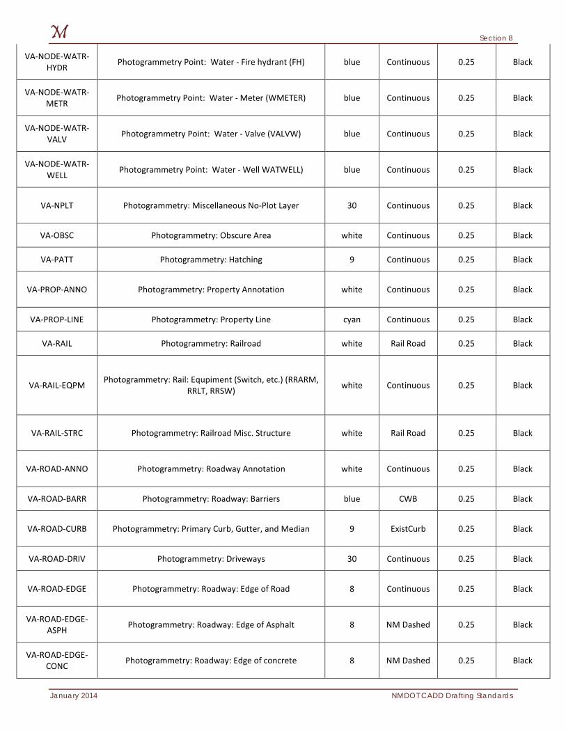
Section 8
January 2014 NMDOT CADD Drafting Standards
VA-NODE-WATR-HYDR Photogrammetry Point: Water - Fire hydrant (FH) blue Continuous 0.25 Black
VA-NODE-WATR-METR Photogrammetry Point: Water - Meter (WMETER) blue Continuous 0.25 Black
VA-NODE-WATR-VALV Photogrammetry Point: Water - Valve (VALVW) blue Continuous 0.25 Black
VA-NODE-WATR-WELL Photogrammetry Point: Water - Well WATWELL) blue Continuous 0.25 Black
VA-NPLT Photogrammetry: Miscellaneous No-Plot Layer 30 Continuous 0.25 Black
VA-OBSC Photogrammetry: Obscure Area white Continuous 0.25 Black
VA-PATT Photogrammetry: Hatching 9 Continuous 0.25 Black
VA-PROP-ANNO Photogrammetry: Property Annotation white Continuous 0.25 Black
VA-PROP-LINE Photogrammetry: Property Line cyan Continuous 0.25 Black
VA-RAIL Photogrammetry: Railroad white Rail Road 0.25 Black
VA-RAIL-EQPM Photogrammetry: Rail: Equpiment (Switch, etc.) (RRARM, RRLT, RRSW) white Continuous 0.25 Black
VA-RAIL-STRC Photogrammetry: Railroad Misc. Structure white Rail Road 0.25 Black
VA-ROAD-ANNO Photogrammetry: Roadway Annotation white Continuous 0.25 Black
VA-ROAD-BARR Photogrammetry: Roadway: Barriers blue CWB 0.25 Black
VA-ROAD-CURB Photogrammetry: Primary Curb, Gutter, and Median 9 ExistCurb 0.25 Black
VA-ROAD-DRIV Photogrammetry: Driveways 30 Continuous 0.25 Black
VA-ROAD-EDGE Photogrammetry: Roadway: Edge of Road 8 Continuous 0.25 Black
VA-ROAD-EDGE-ASPH Photogrammetry: Roadway: Edge of Asphalt 8 NM Dashed 0.25 Black
VA-ROAD-EDGE-CONC Photogrammetry: Roadway: Edge of concrete 8 NM Dashed 0.25 Black
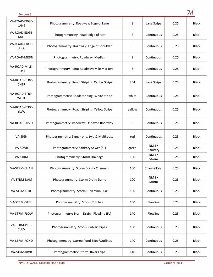
Section 8
NMDOT CADD Drafting Standards January 2014
VA-ROAD-EDGE-LANE Photogrammetry: Roadway: Edge of Lane 8 Lane Stripe 0.25 Black
VA-ROAD-EDGE-MAT Photogrammetry: Road: Edge of Mat 8 Continuous 0.25 Black
VA-ROAD-EDGE-SHOL Photogrammetry: Roadway: Edge of shoulder 8 Continuous 0.25 Black
VA-ROAD-MEDN Photogrammetry: Roadway: Median 8 Continuous 0.25 Black
VA-ROAD-MILE-POST Photogrammetry Point: Roadway: Mile Markers 8 Continuous 0.25 Black
VA-ROAD-STRP-CNTR Photogrammetry: Road: Striping: Center Stripe 254 Lane Stripe 0.25 Black
VA-ROAD-STRP-WHTE Photogrammetry: Road: Striping: White Stripe white Continuous 0.25 Black
VA-ROAD-STRP-YLLW Photogrammetry: Road: Striping: Yellow Stripe yellow Continuous 0.25 Black
VA-ROAD-UPVD Photogrammetry: Roadway: Unpaved Roadway 8 Continuous 0.25 Black
VA-SIGN Photogrammetry: Signs - one, two & Multi post red Continuous 0.25 Black
VA-SSWR Photogrammetry: Sanitary Sewer (SL) green NM EX Sanitary 0.25 Black
VA-STRM Photogrammetry: Storm Drainage 100 NM EX Storm 0.25 Black
VA-STRM-CHAN Photogrammetry: Storm Drain - Channels 100 ChannelExist 0.25 Black
VA-STRM-DAM Photogrammetry: Storm Drain: Dams 100 NM EX Storm 0.25 Black
VA-STRM-DIKE Photogrammetry: Storm: Diversion Dike 100 Continuous 0.25 Black
VA-STRM-DTCH Photogrammetry: Storm: Ditches 100 Flowline 0.25 Black
VA-STRM-FLOW Photogrammetry: Storm Drain - Flowline (FL) 140 Flowline 0.25 Black
VA-STRM-PIPE-CULV Photogrammetry: Storm: Culvert Pipes 100 Continuous 0.25 Black
VA-STRM-POND Photogrammetry: Storm: Pond Edge/Outlines 140 Continuous 0.25 Black
VA-STRM-RIVR Photogrammetry: Storm: River Edge 140 Continuous 0.25 Black
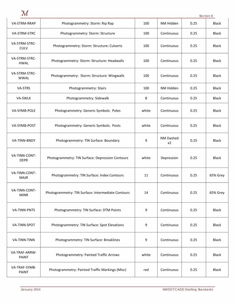
Section 8
January 2014 NMDOT CADD Drafting Standards
VA-STRM-RRAP Photogrammetry: Storm: Rip Rap 100 NM Hidden 0.25 Black
VA-STRM-STRC Photogrammetry: Storm: Structure 100 Continuous 0.25 Black
VA-STRM-STRC-CULV Photogrammetry: Storm: Structure: Culverts 100 Continuous 0.25 Black
VA-STRM-STRC-HWAL Photogrammetry: Storm: Structure: Headwalls 100 Continuous 0.25 Black
VA-STRM-STRC-WWAL Photogrammetry: Storm: Structure: Wingwalls 100 Continuous 0.25 Black
VA-STRS Photogrammetry: Stairs 100 NM Hidden 0.25 Black
VA-SWLK Photogrammetry: Sidewalk 8 Continuous 0.25 Black
VA-SYMB-POLE Photogrammetry: Generic Symbols: Poles white Continuous 0.25 Black
VA-SYMB-POST Photogrammetry: Generic Symbols: Posts white Continuous 0.25 Black
VA-TINN-BNDY Photogrammetry: TIN Surface: Boundary 9 NM Dashed x2 0.25 Black
VA-TINN-CONT-DEPR Photogrammetry: TIN Surface: Depression Contours white Depression 0.25 Black
VA-TINN-CONT-MAJR Photogrammetry: TIN Surface: Index Contours 11 Continuous 0.25 65% Grey
VA-TINN-CONT-MINR Photogrammetry: TIN Surface: Intermediate Contours 14 Continuous 0.25 65% Grey
VA-TINN-PNTS Photogrammetry: TIN Surface: DTM Points 9 Continuous 0.25 Black
VA-TINN-SPOT Photogrammetry: TIN Surface: Spot Elevations 9 Continuous 0.25 Black
VA-TINN-TINN Photogrammetry: TIN Surface: Breaklines 9 Continuous 0.25 Black
VA-TRAF-ARRW-PAINT Photogrammetry: Painted Traffic Arrows white Continuous 0.25 Black
VA-TRAF-SYMB-PAINT Photogrammetry: Painted Traffic Markings (Misc) red Continuous 0.25 Black
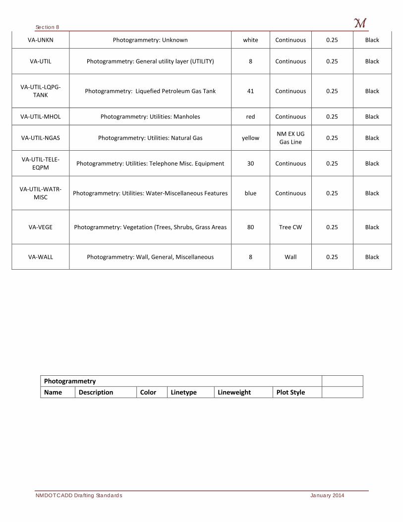
Section 8
NMDOT CADD Drafting Standards January 2014
VA-UNKN Photogrammetry: Unknown white Continuous 0.25 Black
VA-UTIL Photogrammetry: General utility layer (UTILITY) 8 Continuous 0.25 Black
VA-UTIL-LQPG-TANK Photogrammetry: Liquefied Petroleum Gas Tank 41 Continuous 0.25 Black
VA-UTIL-MHOL Photogrammetry: Utilities: Manholes red Continuous 0.25 Black
VA-UTIL-NGAS Photogrammetry: Utilities: Natural Gas yellow NM EX UG Gas Line 0.25 Black
VA-UTIL-TELE-EQPM Photogrammetry: Utilities: Telephone Misc. Equipment 30 Continuous 0.25 Black
VA-UTIL-WATR-MISC Photogrammetry: Utilities: Water-Miscellaneous Features blue Continuous 0.25 Black
VA-VEGE Photogrammetry: Vegetation (Trees, Shrubs, Grass Areas 80 Tree CW 0.25 Black
VA-WALL Photogrammetry: Wall, General, Miscellaneous 8 Wall 0.25 Black
Photogrammetry Name Description Color Linetype Lineweight Plot Style
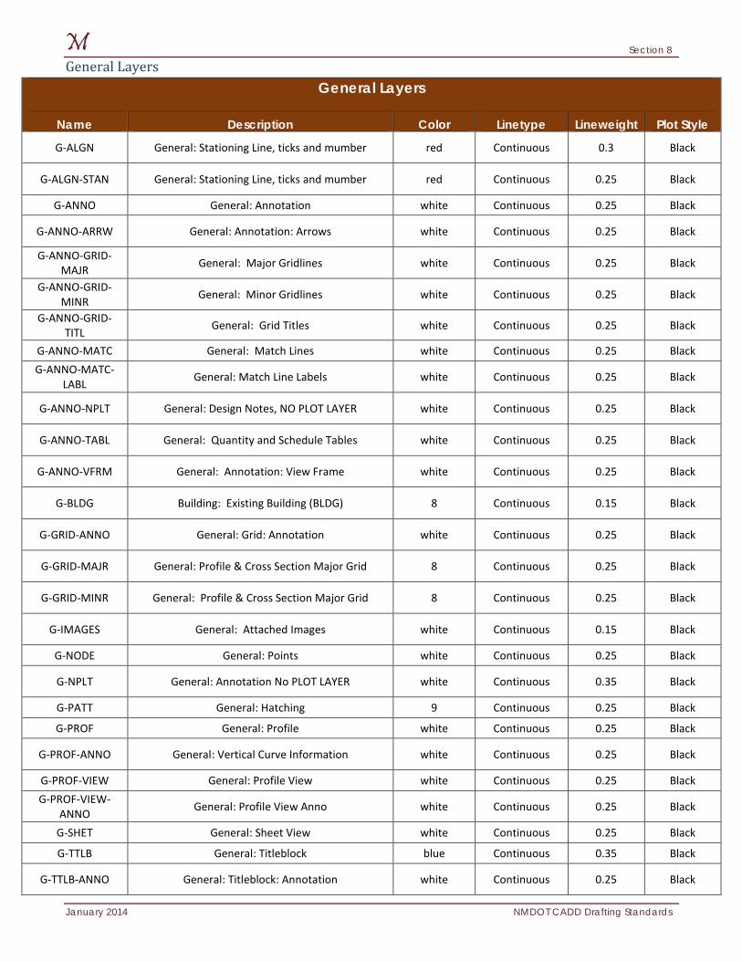
Section 8
January 2014 NMDOT CADD Drafting Standards
General Layers General Layers
Name Description Color Linetype Lineweight Plot Style
G-ALGN General: Stationing Line, ticks and mumber red Continuous 0.3 Black
G-ALGN-STAN General: Stationing Line, ticks and mumber red Continuous 0.25 Black
G-ANNO General: Annotation white Continuous 0.25 Black
G-ANNO-ARRW General: Annotation: Arrows white Continuous 0.25 Black
G-ANNO-GRID-MAJR General: Major Gridlines white Continuous 0.25 Black
G-ANNO-GRID-MINR General: Minor Gridlines white Continuous 0.25 Black
G-ANNO-GRID-TITL General: Grid Titles white Continuous 0.25 Black
G-ANNO-MATC General: Match Lines white Continuous 0.25 Black G-ANNO-MATC-
LABL General: Match Line Labels white Continuous 0.25 Black
G-ANNO-NPLT General: Design Notes, NO PLOT LAYER white Continuous 0.25 Black
G-ANNO-TABL General: Quantity and Schedule Tables white Continuous 0.25 Black
G-ANNO-VFRM General: Annotation: View Frame white Continuous 0.25 Black
G-BLDG Building: Existing Building (BLDG) 8 Continuous 0.15 Black
G-GRID-ANNO General: Grid: Annotation white Continuous 0.25 Black
G-GRID-MAJR General: Profile & Cross Section Major Grid 8 Continuous 0.25 Black
G-GRID-MINR General: Profile & Cross Section Major Grid 8 Continuous 0.25 Black
G-IMAGES General: Attached Images white Continuous 0.15 Black
G-NODE General: Points white Continuous 0.25 Black
G-NPLT General: Annotation No PLOT LAYER white Continuous 0.35 Black
G-PATT General: Hatching 9 Continuous 0.25 Black
G-PROF General: Profile white Continuous 0.25 Black
G-PROF-ANNO General: Vertical Curve Information white Continuous 0.25 Black
G-PROF-VIEW General: Profile View white Continuous 0.25 Black G-PROF-VIEW-
ANNO General: Profile View Anno white Continuous 0.25 Black
G-SHET General: Sheet View white Continuous 0.25 Black
G-TTLB General: Titleblock blue Continuous 0.35 Black
G-TTLB-ANNO General: Titleblock: Annotation white Continuous 0.25 Black
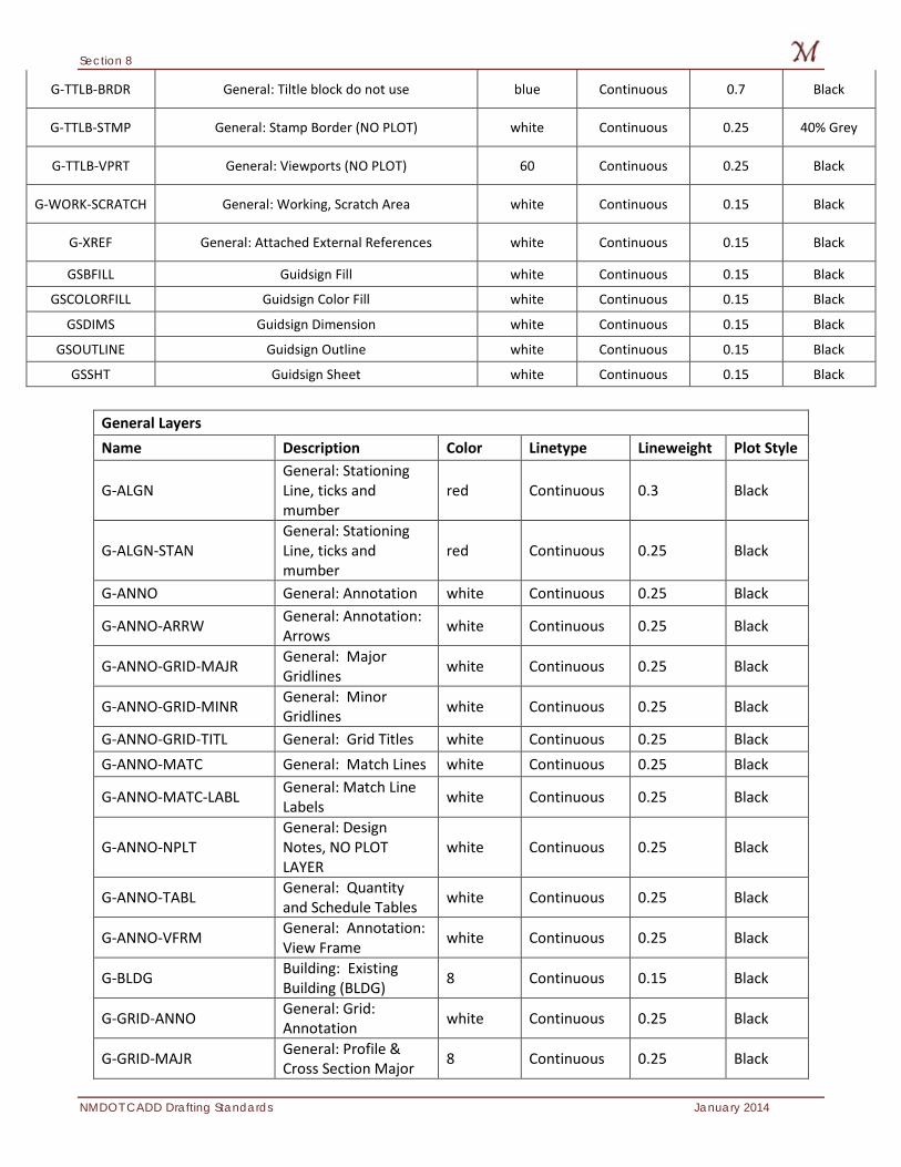
Section 8
NMDOT CADD Drafting Standards January 2014
G-TTLB-BRDR General: Tiltle block do not use blue Continuous 0.7 Black
G-TTLB-STMP General: Stamp Border (NO PLOT) white Continuous 0.25 40% Grey
G-TTLB-VPRT General: Viewports (NO PLOT) 60 Continuous 0.25 Black
G-WORK-SCRATCH General: Working, Scratch Area white Continuous 0.15 Black
G-XREF General: Attached External References white Continuous 0.15 Black
GSBFILL Guidsign Fill white Continuous 0.15 Black
GSCOLORFILL Guidsign Color Fill white Continuous 0.15 Black
GSDIMS Guidsign Dimension white Continuous 0.15 Black
GSOUTLINE Guidsign Outline white Continuous 0.15 Black
GSSHT Guidsign Sheet white Continuous 0.15 Black
General Layers Name Description Color Linetype Lineweight Plot Style
G-ALGN General: Stationing Line, ticks and mumber
red Continuous 0.3 Black
G-ALGN-STAN General: Stationing Line, ticks and mumber
red Continuous 0.25 Black
G-ANNO General: Annotation white Continuous 0.25 Black
G-ANNO-ARRW General: Annotation: Arrows white Continuous 0.25 Black
G-ANNO-GRID-MAJR General: Major Gridlines white Continuous 0.25 Black
G-ANNO-GRID-MINR General: Minor Gridlines white Continuous 0.25 Black
G-ANNO-GRID-TITL General: Grid Titles white Continuous 0.25 Black G-ANNO-MATC General: Match Lines white Continuous 0.25 Black
G-ANNO-MATC-LABL General: Match Line Labels white Continuous 0.25 Black
G-ANNO-NPLT General: Design Notes, NO PLOT LAYER
white Continuous 0.25 Black
G-ANNO-TABL General: Quantity and Schedule Tables white Continuous 0.25 Black
G-ANNO-VFRM General: Annotation: View Frame white Continuous 0.25 Black
G-BLDG Building: Existing Building (BLDG) 8 Continuous 0.15 Black
G-GRID-ANNO General: Grid: Annotation white Continuous 0.25 Black
G-GRID-MAJR General: Profile & Cross Section Major 8 Continuous 0.25 Black
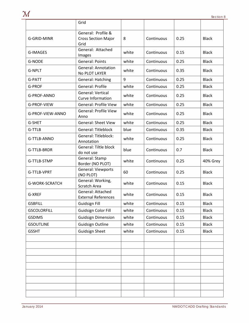
Section 8
January 2014 NMDOT CADD Drafting Standards
Grid
G-GRID-MINR General: Profile & Cross Section Major Grid
8 Continuous 0.25 Black
G-IMAGES General: Attached Images white Continuous 0.15 Black
G-NODE General: Points white Continuous 0.25 Black
G-NPLT General: Annotation No PLOT LAYER white Continuous 0.35 Black
G-PATT General: Hatching 9 Continuous 0.25 Black G-PROF General: Profile white Continuous 0.25 Black
G-PROF-ANNO General: Vertical Curve Information white Continuous 0.25 Black
G-PROF-VIEW General: Profile View white Continuous 0.25 Black
G-PROF-VIEW-ANNO General: Profile View Anno white Continuous 0.25 Black
G-SHET General: Sheet View white Continuous 0.25 Black G-TTLB General: Titleblock blue Continuous 0.35 Black
G-TTLB-ANNO General: Titleblock: Annotation white Continuous 0.25 Black
G-TTLB-BRDR General: Tiltle block do not use blue Continuous 0.7 Black
G-TTLB-STMP General: Stamp Border (NO PLOT) white Continuous 0.25 40% Grey
G-TTLB-VPRT General: Viewports (NO PLOT) 60 Continuous 0.25 Black
G-WORK-SCRATCH General: Working, Scratch Area white Continuous 0.15 Black
G-XREF General: Attached External References white Continuous 0.15 Black
GSBFILL Guidsign Fill white Continuous 0.15 Black GSCOLORFILL Guidsign Color Fill white Continuous 0.15 Black GSDIMS Guidsign Dimension white Continuous 0.15 Black GSOUTLINE Guidsign Outline white Continuous 0.15 Black GSSHT Guidsign Sheet white Continuous 0.15 Black
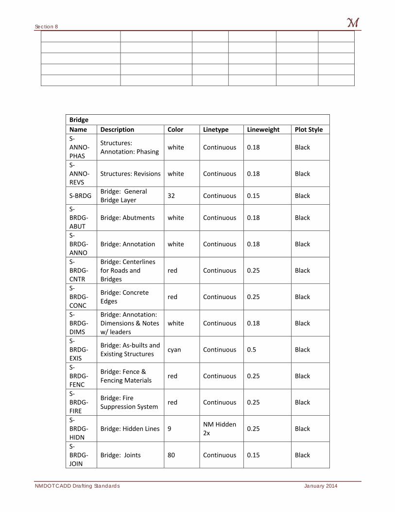
Section 8
NMDOT CADD Drafting Standards January 2014
Bridge Name Description Color Linetype Lineweight Plot Style S-ANNO-PHAS
Structures: Annotation: Phasing white Continuous 0.18 Black
S-ANNO-REVS
Structures: Revisions white Continuous 0.18 Black
S-BRDG Bridge: General Bridge Layer 32 Continuous 0.15 Black
S-BRDG-ABUT
Bridge: Abutments white Continuous 0.18 Black
S-BRDG-ANNO
Bridge: Annotation white Continuous 0.18 Black
S-BRDG-CNTR
Bridge: Centerlines for Roads and Bridges
red Continuous 0.25 Black
S-BRDG-CONC
Bridge: Concrete Edges red Continuous 0.25 Black
S-BRDG-DIMS
Bridge: Annotation: Dimensions & Notes w/ leaders
white Continuous 0.18 Black
S-BRDG-EXIS
Bridge: As-builts and Existing Structures cyan Continuous 0.5 Black
S-BRDG-FENC
Bridge: Fence & Fencing Materials red Continuous 0.25 Black
S-BRDG-FIRE
Bridge: Fire Suppression System red Continuous 0.25 Black
S-BRDG-HIDN
Bridge: Hidden Lines 9 NM Hidden 2x 0.25 Black
S-BRDG-JOIN
Bridge: Joints 80 Continuous 0.15 Black
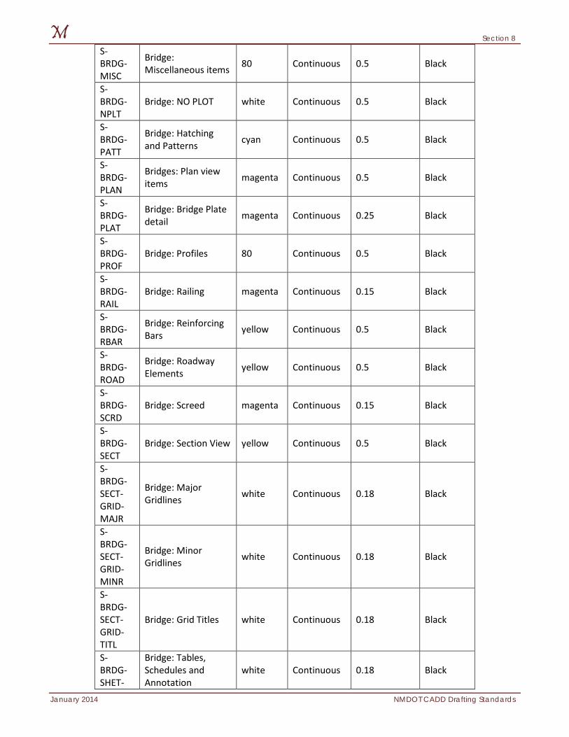
Section 8
January 2014 NMDOT CADD Drafting Standards
S-BRDG-MISC
Bridge: Miscellaneous items 80 Continuous 0.5 Black
S-BRDG-NPLT
Bridge: NO PLOT white Continuous 0.5 Black
S-BRDG-PATT
Bridge: Hatching and Patterns cyan Continuous 0.5 Black
S-BRDG-PLAN
Bridges: Plan view items magenta Continuous 0.5 Black
S-BRDG-PLAT
Bridge: Bridge Plate detail magenta Continuous 0.25 Black
S-BRDG-PROF
Bridge: Profiles 80 Continuous 0.5 Black
S-BRDG-RAIL
Bridge: Railing magenta Continuous 0.15 Black
S-BRDG-RBAR
Bridge: Reinforcing Bars yellow Continuous 0.5 Black
S-BRDG-ROAD
Bridge: Roadway Elements yellow Continuous 0.5 Black
S-BRDG-SCRD
Bridge: Screed magenta Continuous 0.15 Black
S-BRDG-SECT
Bridge: Section View yellow Continuous 0.5 Black
S-BRDG-SECT-GRID-MAJR
Bridge: Major Gridlines white Continuous 0.18 Black
S-BRDG-SECT-GRID-MINR
Bridge: Minor Gridlines white Continuous 0.18 Black
S-BRDG-SECT-GRID-TITL
Bridge: Grid Titles white Continuous 0.18 Black
S-BRDG-SHET-
Bridge: Tables, Schedules and Annotation
white Continuous 0.18 Black
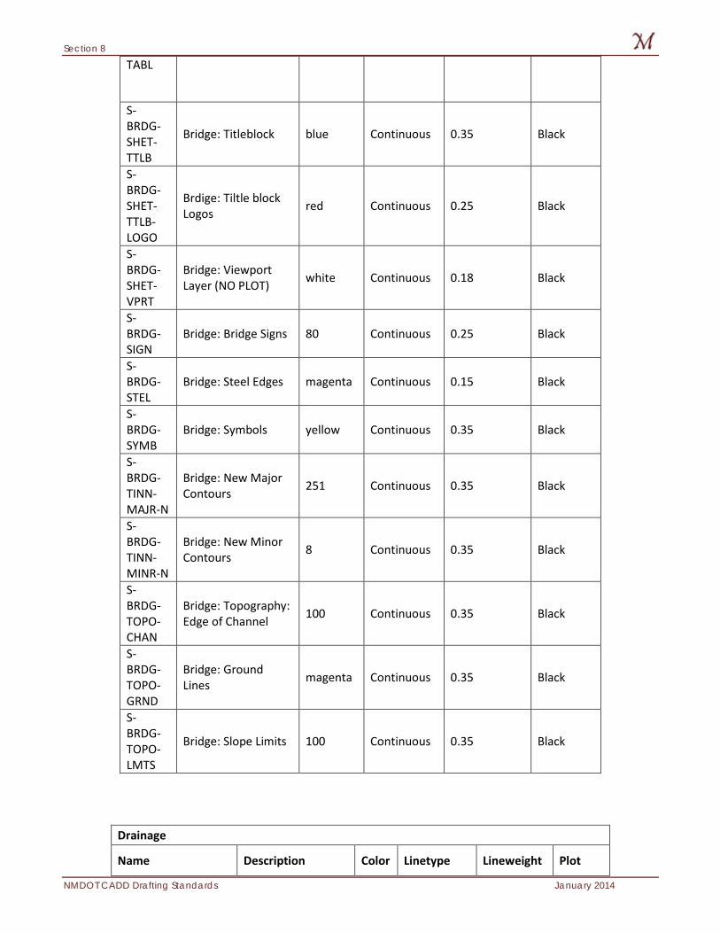
Section 8
NMDOT CADD Drafting Standards January 2014
TABL
S-BRDG-SHET-TTLB
Bridge: Titleblock blue Continuous 0.35 Black
S-BRDG-SHET-TTLB-LOGO
Brdige: Tiltle block Logos red Continuous 0.25 Black
S-BRDG-SHET-VPRT
Bridge: Viewport Layer (NO PLOT) white Continuous 0.18 Black
S-BRDG-SIGN
Bridge: Bridge Signs 80 Continuous 0.25 Black
S-BRDG-STEL
Bridge: Steel Edges magenta Continuous 0.15 Black
S-BRDG-SYMB
Bridge: Symbols yellow Continuous 0.35 Black
S-BRDG-TINN-MAJR-N
Bridge: New Major Contours 251 Continuous 0.35 Black
S-BRDG-TINN-MINR-N
Bridge: New Minor Contours 8 Continuous 0.35 Black
S-BRDG-TOPO-CHAN
Bridge: Topography: Edge of Channel 100 Continuous 0.35 Black
S-BRDG-TOPO-GRND
Bridge: Ground Lines magenta Continuous 0.35 Black
S-BRDG-TOPO-LMTS
Bridge: Slope Limits 100 Continuous 0.35 Black
Drainage
Name Description Color Linetype Lineweight Plot
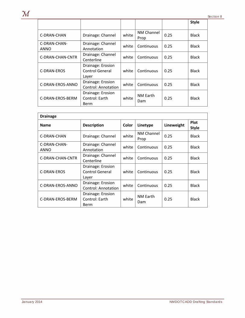
Section 8
January 2014 NMDOT CADD Drafting Standards
Style
C-DRAN-CHAN Drainage: Channel white NM Channel Prop 0.25 Black
C-DRAN-CHAN-ANNO
Drainage: Channel Annotation white Continuous 0.25 Black
C-DRAN-CHAN-CNTR Drainage: Channel Centerline white Continuous 0.25 Black
C-DRAN-EROS Drainage: Erosion Control General Layer
white Continuous 0.25 Black
C-DRAN-EROS-ANNO Drainage: Erosion Control: Annotation white Continuous 0.25 Black
C-DRAN-EROS-BERM Drainage: Erosion Control: Earth Berm
white NM Earth Dam 0.25 Black
Drainage
Name Description Color Linetype Lineweight Plot Style
C-DRAN-CHAN Drainage: Channel white NM Channel Prop 0.25 Black
C-DRAN-CHAN-ANNO
Drainage: Channel Annotation white Continuous 0.25 Black
C-DRAN-CHAN-CNTR Drainage: Channel Centerline white Continuous 0.25 Black
C-DRAN-EROS Drainage: Erosion Control General Layer
white Continuous 0.25 Black
C-DRAN-EROS-ANNO Drainage: Erosion Control: Annotation white Continuous 0.25 Black
C-DRAN-EROS-BERM Drainage: Erosion Control: Earth Berm
white NM Earth Dam 0.25 Black
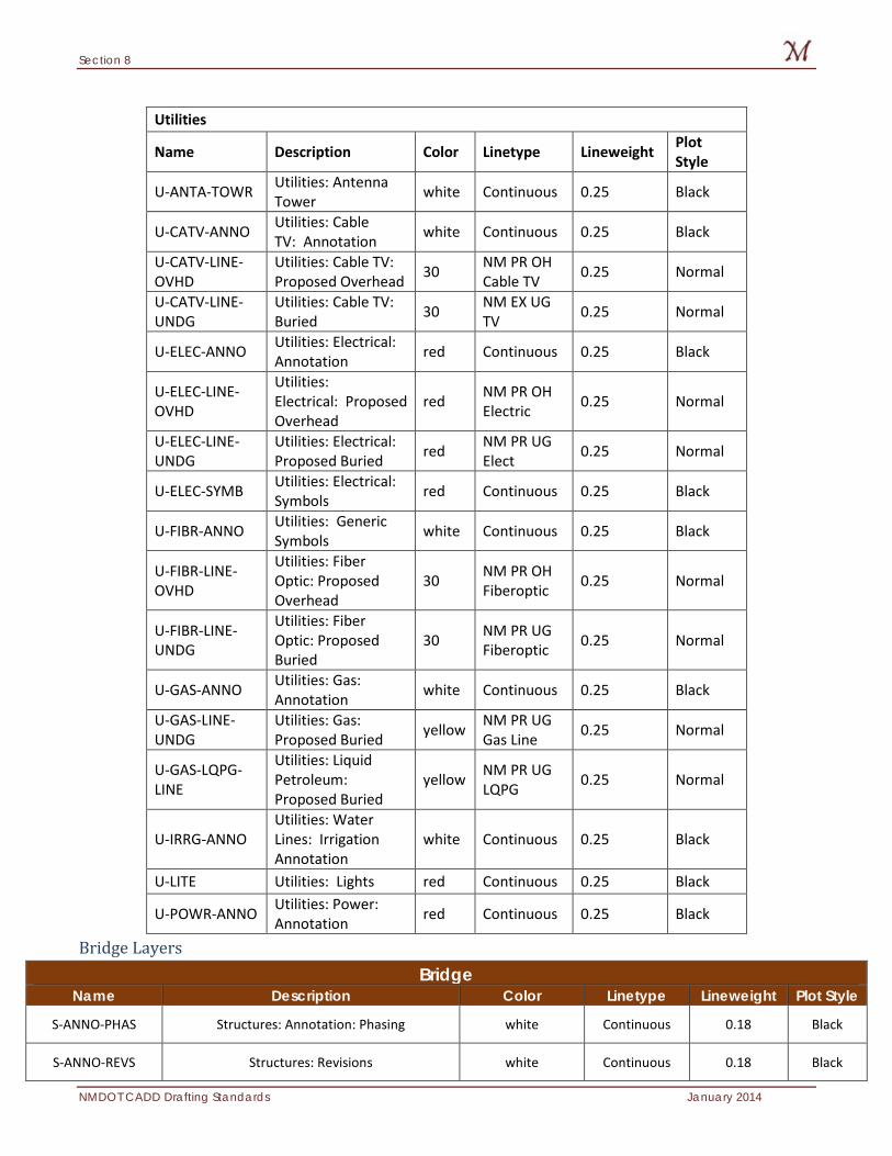
Section 8
NMDOT CADD Drafting Standards January 2014
Utilities
Name Description Color Linetype Lineweight Plot Style
U-ANTA-TOWR Utilities: Antenna Tower white Continuous 0.25 Black
U-CATV-ANNO Utilities: Cable TV: Annotation white Continuous 0.25 Black
U-CATV-LINE-OVHD
Utilities: Cable TV: Proposed Overhead 30 NM PR OH
Cable TV 0.25 Normal
U-CATV-LINE-UNDG
Utilities: Cable TV: Buried 30 NM EX UG
TV 0.25 Normal
U-ELEC-ANNO Utilities: Electrical: Annotation red Continuous 0.25 Black
U-ELEC-LINE-OVHD
Utilities: Electrical: Proposed Overhead
red NM PR OH Electric 0.25 Normal
U-ELEC-LINE-UNDG
Utilities: Electrical: Proposed Buried red NM PR UG
Elect 0.25 Normal
U-ELEC-SYMB Utilities: Electrical: Symbols red Continuous 0.25 Black
U-FIBR-ANNO Utilities: Generic Symbols white Continuous 0.25 Black
U-FIBR-LINE-OVHD
Utilities: Fiber Optic: Proposed Overhead
30 NM PR OH Fiberoptic 0.25 Normal
U-FIBR-LINE-UNDG
Utilities: Fiber Optic: Proposed Buried
30 NM PR UG Fiberoptic 0.25 Normal
U-GAS-ANNO Utilities: Gas: Annotation white Continuous 0.25 Black
U-GAS-LINE-UNDG
Utilities: Gas: Proposed Buried yellow NM PR UG
Gas Line 0.25 Normal
U-GAS-LQPG-LINE
Utilities: Liquid Petroleum: Proposed Buried
yellow NM PR UG LQPG 0.25 Normal
U-IRRG-ANNO Utilities: Water Lines: Irrigation Annotation
white Continuous 0.25 Black
U-LITE Utilities: Lights red Continuous 0.25 Black
U-POWR-ANNO Utilities: Power: Annotation red Continuous 0.25 Black
Bridge Layers
Bridge Name Description Color Linetype Lineweight Plot Style
S-ANNO-PHAS Structures: Annotation: Phasing white Continuous 0.18 Black
S-ANNO-REVS Structures: Revisions white Continuous 0.18 Black
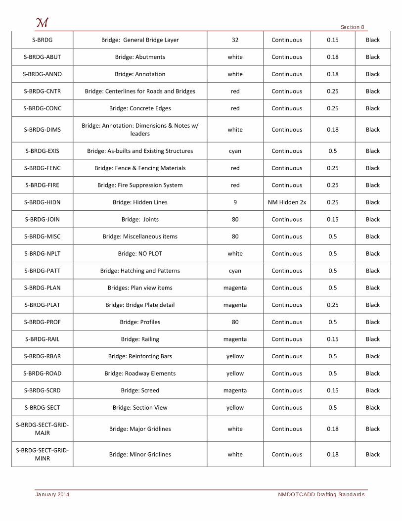
Section 8
January 2014 NMDOT CADD Drafting Standards
S-BRDG Bridge: General Bridge Layer 32 Continuous 0.15 Black
S-BRDG-ABUT Bridge: Abutments white Continuous 0.18 Black
S-BRDG-ANNO Bridge: Annotation white Continuous 0.18 Black
S-BRDG-CNTR Bridge: Centerlines for Roads and Bridges red Continuous 0.25 Black
S-BRDG-CONC Bridge: Concrete Edges red Continuous 0.25 Black
S-BRDG-DIMS Bridge: Annotation: Dimensions & Notes w/ leaders white Continuous 0.18 Black
S-BRDG-EXIS Bridge: As-builts and Existing Structures cyan Continuous 0.5 Black
S-BRDG-FENC Bridge: Fence & Fencing Materials red Continuous 0.25 Black
S-BRDG-FIRE Bridge: Fire Suppression System red Continuous 0.25 Black
S-BRDG-HIDN Bridge: Hidden Lines 9 NM Hidden 2x 0.25 Black
S-BRDG-JOIN Bridge: Joints 80 Continuous 0.15 Black
S-BRDG-MISC Bridge: Miscellaneous items 80 Continuous 0.5 Black
S-BRDG-NPLT Bridge: NO PLOT white Continuous 0.5 Black
S-BRDG-PATT Bridge: Hatching and Patterns cyan Continuous 0.5 Black
S-BRDG-PLAN Bridges: Plan view items magenta Continuous 0.5 Black
S-BRDG-PLAT Bridge: Bridge Plate detail magenta Continuous 0.25 Black
S-BRDG-PROF Bridge: Profiles 80 Continuous 0.5 Black
S-BRDG-RAIL Bridge: Railing magenta Continuous 0.15 Black
S-BRDG-RBAR Bridge: Reinforcing Bars yellow Continuous 0.5 Black
S-BRDG-ROAD Bridge: Roadway Elements yellow Continuous 0.5 Black
S-BRDG-SCRD Bridge: Screed magenta Continuous 0.15 Black
S-BRDG-SECT Bridge: Section View yellow Continuous 0.5 Black
S-BRDG-SECT-GRID-MAJR Bridge: Major Gridlines white Continuous 0.18 Black
S-BRDG-SECT-GRID-MINR Bridge: Minor Gridlines white Continuous 0.18 Black
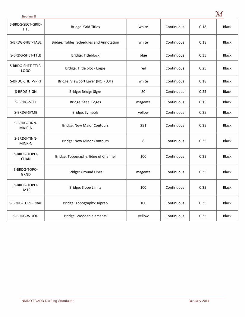
Section 8
NMDOT CADD Drafting Standards January 2014
S-BRDG-SECT-GRID-TITL Bridge: Grid Titles white Continuous 0.18 Black
S-BRDG-SHET-TABL Bridge: Tables, Schedules and Annotation white Continuous 0.18 Black
S-BRDG-SHET-TTLB Bridge: Titleblock blue Continuous 0.35 Black
S-BRDG-SHET-TTLB-LOGO Brdige: Tiltle block Logos red Continuous 0.25 Black
S-BRDG-SHET-VPRT Bridge: Viewport Layer (NO PLOT) white Continuous 0.18 Black
S-BRDG-SIGN Bridge: Bridge Signs 80 Continuous 0.25 Black
S-BRDG-STEL Bridge: Steel Edges magenta Continuous 0.15 Black
S-BRDG-SYMB Bridge: Symbols yellow Continuous 0.35 Black
S-BRDG-TINN-MAJR-N Bridge: New Major Contours 251 Continuous 0.35 Black
S-BRDG-TINN-MINR-N Bridge: New Minor Contours 8 Continuous 0.35 Black
S-BRDG-TOPO-CHAN Bridge: Topography: Edge of Channel 100 Continuous 0.35 Black
S-BRDG-TOPO-GRND Bridge: Ground Lines magenta Continuous 0.35 Black
S-BRDG-TOPO-LMTS Bridge: Slope Limits 100 Continuous 0.35 Black
S-BRDG-TOPO-RRAP Bridge: Topography: Riprap 100 Continuous 0.35 Black
S-BRDG-WOOD Bridge: Wooden elements yellow Continuous 0.35 Black
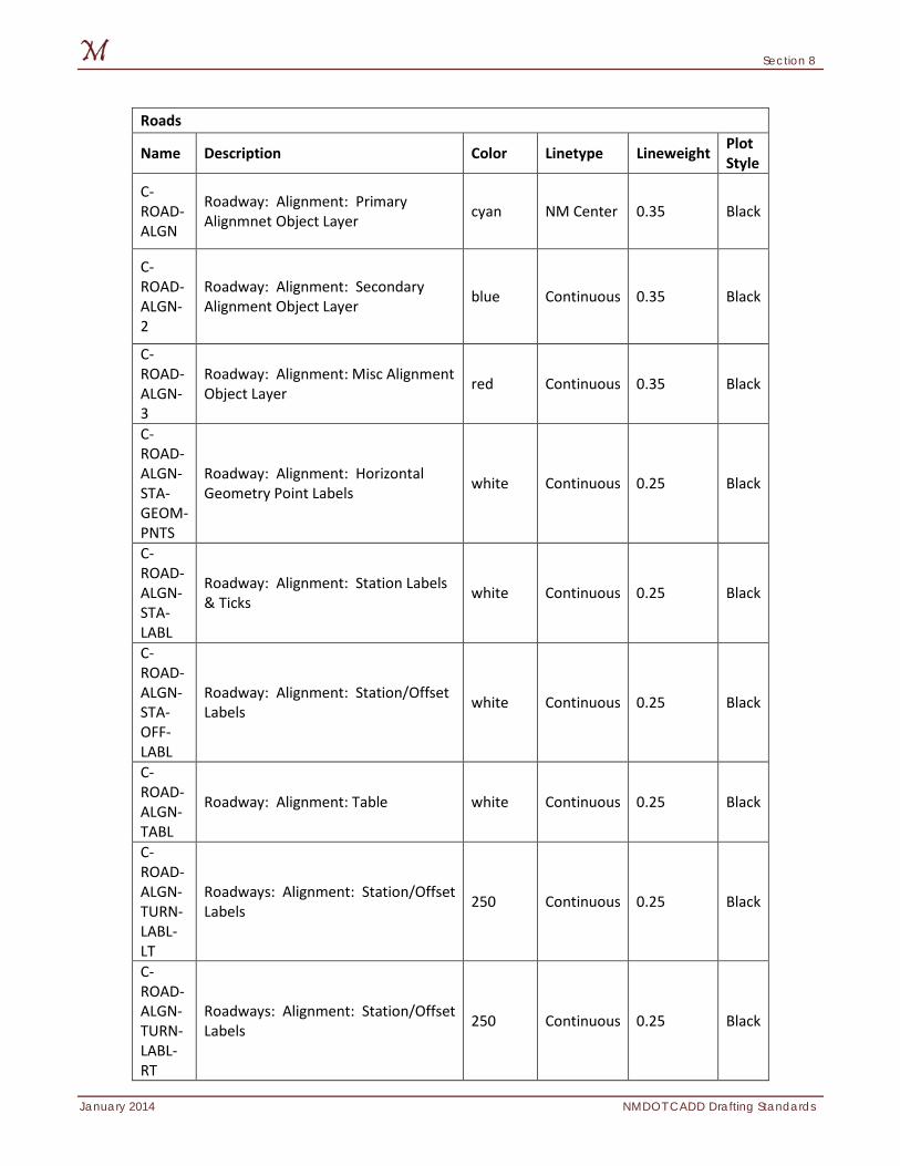
Section 8
January 2014 NMDOT CADD Drafting Standards
Roads
Name Description Color Linetype Lineweight Plot Style
C-ROAD-ALGN
Roadway: Alignment: Primary Alignmnet Object Layer cyan NM Center 0.35 Black
C-ROAD-ALGN-2
Roadway: Alignment: Secondary Alignment Object Layer blue Continuous 0.35 Black
C-ROAD-ALGN-3
Roadway: Alignment: Misc Alignment Object Layer red Continuous 0.35 Black
C-ROAD-ALGN-STA-GEOM-PNTS
Roadway: Alignment: Horizontal Geometry Point Labels white Continuous 0.25 Black
C-ROAD-ALGN-STA-LABL
Roadway: Alignment: Station Labels & Ticks white Continuous 0.25 Black
C-ROAD-ALGN-STA-OFF-LABL
Roadway: Alignment: Station/Offset Labels white Continuous 0.25 Black
C-ROAD-ALGN-TABL
Roadway: Alignment: Table white Continuous 0.25 Black
C-ROAD-ALGN-TURN-LABL-LT
Roadways: Alignment: Station/Offset Labels 250 Continuous 0.25 Black
C-ROAD-ALGN-TURN-LABL-RT
Roadways: Alignment: Station/Offset Labels 250 Continuous 0.25 Black
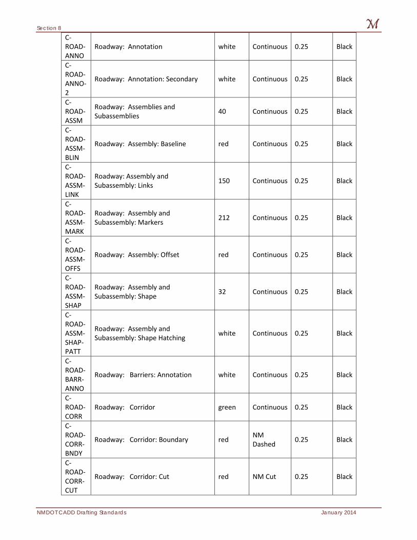
Section 8
NMDOT CADD Drafting Standards January 2014
C-ROAD-ANNO
Roadway: Annotation white Continuous 0.25 Black
C-ROAD-ANNO-2
Roadway: Annotation: Secondary white Continuous 0.25 Black
C-ROAD-ASSM
Roadway: Assemblies and Subassemblies 40 Continuous 0.25 Black
C-ROAD-ASSM-BLIN
Roadway: Assembly: Baseline red Continuous 0.25 Black
C-ROAD-ASSM-LINK
Roadway: Assembly and Subassembly: Links 150 Continuous 0.25 Black
C-ROAD-ASSM-MARK
Roadway: Assembly and Subassembly: Markers 212 Continuous 0.25 Black
C-ROAD-ASSM-OFFS
Roadway: Assembly: Offset red Continuous 0.25 Black
C-ROAD-ASSM-SHAP
Roadway: Assembly and Subassembly: Shape 32 Continuous 0.25 Black
C-ROAD-ASSM-SHAP-PATT
Roadway: Assembly and Subassembly: Shape Hatching white Continuous 0.25 Black
C-ROAD-BARR-ANNO
Roadway: Barriers: Annotation white Continuous 0.25 Black
C-ROAD-CORR
Roadway: Corridor green Continuous 0.25 Black
C-ROAD-CORR-BNDY
Roadway: Corridor: Boundary red NM Dashed 0.25 Black
C-ROAD-CORR-CUT
Roadway: Corridor: Cut red NM Cut 0.25 Black
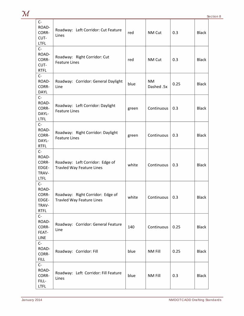
Section 8
January 2014 NMDOT CADD Drafting Standards
C-ROAD-CORR-CUT-LTFL
Roadway: Left Corridor: Cut Feature Lines red NM Cut 0.3 Black
C-ROAD-CORR-CUT-RTFL
Roadway: Right Corridor: Cut Feature Lines red NM Cut 0.3 Black
C-ROAD-CORR-DAYL
Roadway: Corridor: General Daylight Line blue NM
Dashed .5x 0.25 Black
C-ROAD-CORR-DAYL-LTFL
Roadway: Left Corridor: Daylight Feature Lines green Continuous 0.3 Black
C-ROAD-CORR-DAYL-RTFL
Roadway: Right Corridor: Daylight Feature Lines green Continuous 0.3 Black
C-ROAD-CORR-EDGE-TRAV-LTFL
Roadway: Left Corridor: Edge of Travled Way Feature Lines white Continuous 0.3 Black
C-ROAD-CORR-EDGE-TRAV-RTFL
Roadway: Right Corridor: Edge of Travled Way Feature Lines white Continuous 0.3 Black
C-ROAD-CORR-FEAT-LINE
Roadway: Corridor: General Feature Line 140 Continuous 0.25 Black
C-ROAD-CORR-FILL
Roadway: Corridor: Fill blue NM Fill 0.25 Black
C-ROAD-CORR-FILL-LTFL
Roadway: Left Corridor: Fill Feature Lines blue NM Fill 0.3 Black
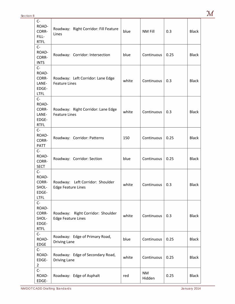
Section 8
NMDOT CADD Drafting Standards January 2014
C-ROAD-CORR-FILL-RTFL
Roadway: Right Corridor: Fill Feature Lines blue NM Fill 0.3 Black
C-ROAD-CORR-INTS
Roadway: Corridor: Intersection blue Continuous 0.25 Black
C-ROAD-CORR-LANE-EDGE-LTFL
Roadway: Left Corridor: Lane Edge Feature Lines white Continuous 0.3 Black
C-ROAD-CORR-LANE-EDGE-RTFL
Roadway: Right Corridor: Lane Edge Feature Lines white Continuous 0.3 Black
C-ROAD-CORR-PATT
Roadway: Corridor: Patterns 150 Continuous 0.25 Black
C-ROAD-CORR-SECT
Roadway: Corridor: Section blue Continuous 0.25 Black
C-ROAD-CORR-SHOL-EDGE-LTFL
Roadway: Left Corridor: Shoulder Edge Feature Lines white Continuous 0.3 Black
C-ROAD-CORR-SHOL-EDGE-RTFL
Roadway: Right Corridor: Shoulder Edge Feature Lines white Continuous 0.3 Black
C-ROAD-EDGE
Roadway: Edge of Primary Road, Driving Lane blue Continuous 0.25 Black
C-ROAD-EDGE-2
Roadway: Edge of Secondary Road, Driving Lane white Continuous 0.25 Black
C-ROAD-EDGE-
Roadway: Edge of Asphalt red NM Hidden 0.25 Black
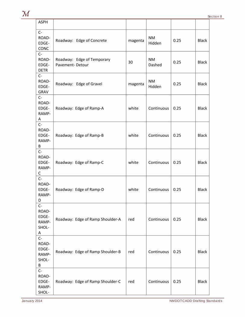
Section 8
January 2014 NMDOT CADD Drafting Standards
ASPH
C-ROAD-EDGE-CONC
Roadway: Edge of Concrete magenta NM Hidden 0.25 Black
C-ROAD-EDGE-DETR
Roadway: Edge of Temporary Pavement- Detour 30 NM
Dashed 0.25 Black
C-ROAD-EDGE-GRAV
Roadway: Edge of Gravel magenta NM Hidden 0.25 Black
C-ROAD-EDGE-RAMP-A
Roadway: Edge of Ramp-A white Continuous 0.25 Black
C-ROAD-EDGE-RAMP-B
Roadway: Edge of Ramp-B white Continuous 0.25 Black
C-ROAD-EDGE-RAMP-C
Roadway: Edge of Ramp-C white Continuous 0.25 Black
C-ROAD-EDGE-RAMP-D
Roadway: Edge of Ramp-D white Continuous 0.25 Black
C-ROAD-EDGE-RAMP-SHOL-A
Roadway: Edge of Ramp Shoulder-A red Continuous 0.25 Black
C-ROAD-EDGE-RAMP-SHOL-B
Roadway: Edge of Ramp Shoulder-B red Continuous 0.25 Black
C-ROAD-EDGE-RAMP-SHOL-
Roadway: Edge of Ramp Shoulder-C red Continuous 0.25 Black
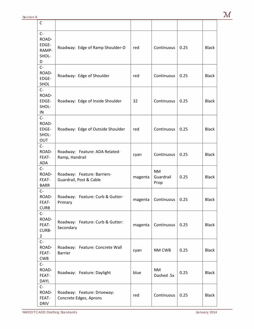
Section 8
NMDOT CADD Drafting Standards January 2014
C
C-ROAD-EDGE-RAMP-SHOL-D
Roadway: Edge of Ramp Shoulder-D red Continuous 0.25 Black
C-ROAD-EDGE-SHOL
Roadway: Edge of Shoulder red Continuous 0.25 Black
C-ROAD-EDGE-SHOL-IN
Roadway: Edge of Inside Shoulder 32 Continuous 0.25 Black
C-ROAD-EDGE-SHOL-OUT
Roadway: Edge of Outside Shoulder red Continuous 0.25 Black
C-ROAD-FEAT-ADA
Roadway: Feature: ADA Related-Ramp, Handrail cyan Continuous 0.25 Black
C-ROAD-FEAT-BARR
Roadway: Feature: Barriers-Guardrail, Post & Cable magenta
NM Guardrail Prop
0.25 Black
C-ROAD-FEAT-CURB
Roadway: Feature: Curb & Gutter-Primary magenta Continuous 0.25 Black
C-ROAD-FEAT-CURB-2
Roadway: Feature: Curb & Gutter: Secondary magenta Continuous 0.25 Black
C-ROAD-FEAT-CWB
Roadway: Feature: Concrete Wall Barrier cyan NM CWB 0.25 Black
C-ROAD-FEAT-DAYL
Roadway: Feature: Daylight blue NM Dashed .5x 0.25 Black
C-ROAD-FEAT-DRIV
Roadway: Feature: Driveway: Concrete Edges, Aprons red Continuous 0.25 Black
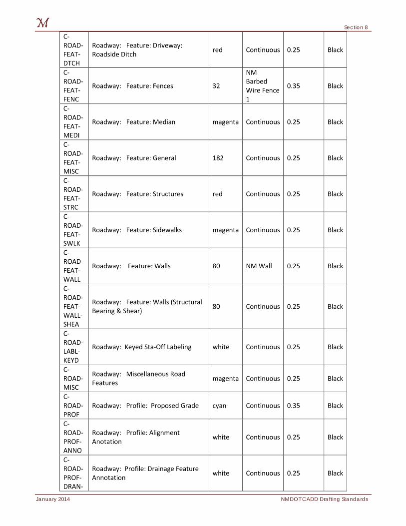
Section 8
January 2014 NMDOT CADD Drafting Standards
C-ROAD-FEAT-DTCH
Roadway: Feature: Driveway: Roadside Ditch red Continuous 0.25 Black
C-ROAD-FEAT-FENC
Roadway: Feature: Fences 32
NM Barbed Wire Fence 1
0.35 Black
C-ROAD-FEAT-MEDI
Roadway: Feature: Median magenta Continuous 0.25 Black
C-ROAD-FEAT-MISC
Roadway: Feature: General 182 Continuous 0.25 Black
C-ROAD-FEAT-STRC
Roadway: Feature: Structures red Continuous 0.25 Black
C-ROAD-FEAT-SWLK
Roadway: Feature: Sidewalks magenta Continuous 0.25 Black
C-ROAD-FEAT-WALL
Roadway: Feature: Walls 80 NM Wall 0.25 Black
C-ROAD-FEAT-WALL-SHEA
Roadway: Feature: Walls (Structural Bearing & Shear) 80 Continuous 0.25 Black
C-ROAD-LABL-KEYD
Roadway: Keyed Sta-Off Labeling white Continuous 0.25 Black
C-ROAD-MISC
Roadway: Miscellaneous Road Features magenta Continuous 0.25 Black
C-ROAD-PROF
Roadway: Profile: Proposed Grade cyan Continuous 0.35 Black
C-ROAD-PROF-ANNO
Roadway: Profile: Alignment Anotation white Continuous 0.25 Black
C-ROAD-PROF-DRAN-
Roadway: Profile: Drainage Feature Annotation white Continuous 0.25 Black
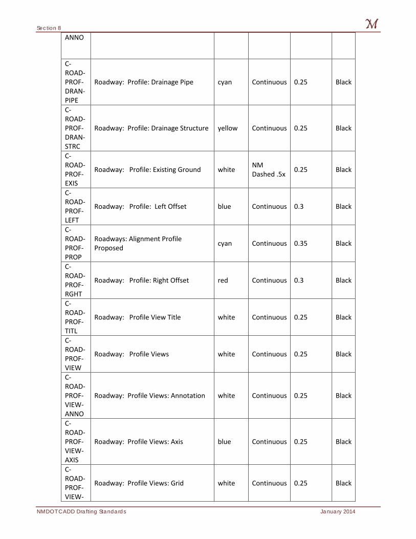
Section 8
NMDOT CADD Drafting Standards January 2014
ANNO
C-ROAD-PROF-DRAN-PIPE
Roadway: Profile: Drainage Pipe cyan Continuous 0.25 Black
C-ROAD-PROF-DRAN-STRC
Roadway: Profile: Drainage Structure yellow Continuous 0.25 Black
C-ROAD-PROF-EXIS
Roadway: Profile: Existing Ground white NM Dashed .5x 0.25 Black
C-ROAD-PROF-LEFT
Roadway: Profile: Left Offset blue Continuous 0.3 Black
C-ROAD-PROF-PROP
Roadways: Alignment Profile Proposed cyan Continuous 0.35 Black
C-ROAD-PROF-RGHT
Roadway: Profile: Right Offset red Continuous 0.3 Black
C-ROAD-PROF-TITL
Roadway: Profile View Title white Continuous 0.25 Black
C-ROAD-PROF-VIEW
Roadway: Profile Views white Continuous 0.25 Black
C-ROAD-PROF-VIEW-ANNO
Roadway: Profile Views: Annotation white Continuous 0.25 Black
C-ROAD-PROF-VIEW-AXIS
Roadway: Profile Views: Axis blue Continuous 0.25 Black
C-ROAD-PROF-VIEW-
Roadway: Profile Views: Grid white Continuous 0.25 Black
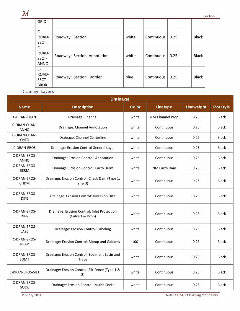
Section 8
January 2014 NMDOT CADD Drafting Standards
GRID
C-ROAD-SECT
Roadway: Section white Continuous 0.25 Black
C-ROAD-SECT-ANNO
Roadway: Section: Annotation white Continuous 0.25 Black
C-ROAD-SECT-BRDR
Roadway: Section: Border blue Continuous 0.25 Black
Drainage Layers Drainage
Name Description Color Linetype Lineweight Plot Style
C-DRAN-CHAN Drainage: Channel white NM Channel Prop 0.25 Black
C-DRAN-CHAN-ANNO Drainage: Channel Annotation white Continuous 0.25 Black
C-DRAN-CHAN-CNTR Drainage: Channel Centerline white Continuous 0.25 Black
C-DRAN-EROS Drainage: Erosion Control General Layer white Continuous 0.25 Black
C-DRAN-EROS-ANNO Drainage: Erosion Control: Annotation white Continuous 0.25 Black
C-DRAN-EROS-BERM Drainage: Erosion Control: Earth Berm white NM Earth Dam 0.25 Black
C-DRAN-EROS-CHDM
Drainage: Erosion Control: Check Dam (Type 1, 2, & 3) white Continuous 0.25 Black
C-DRAN-EROS-DIKE Drainage: Erosion Control: Diversion Dike white Continuous 0.25 Black
C-DRAN-EROS-INPR
Drainage: Erosion Control: Inlet Protection (Culvert & Drop) white Continuous 0.25 Black
C-DRAN-EROS-LABL Drainage: Erosion Control: Labeling white Continuous 0.25 Black
C-DRAN-EROS-RRAP Drainage: Erosion Control: Riprap and Gabions 100 Continuous 0.25 Black
C-DRAN-EROS-SDMT
Drainage: Erosion Control: Sediment Basin and Traps white Continuous 0.25 Black
C-DRAN-EROS-SILT Drainage: Erosion Control: Silt Fence (Type 1 & 2) white Continuous 0.25 Black
C-DRAN-EROS-SOCK Drainage: Erosion Control: Mulch Socks white Continuous 0.25 Black
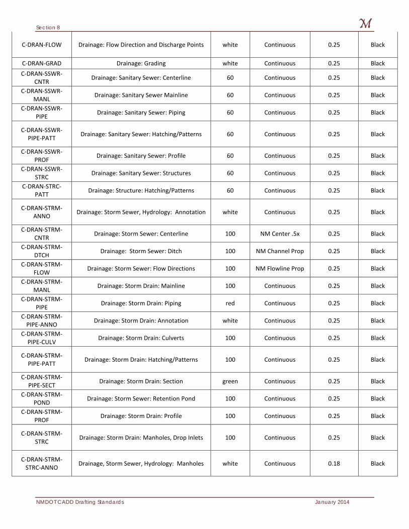
Section 8
NMDOT CADD Drafting Standards January 2014
C-DRAN-FLOW Drainage: Flow Direction and Discharge Points white Continuous 0.25 Black
C-DRAN-GRAD Drainage: Grading white Continuous 0.25 Black C-DRAN-SSWR-
CNTR Drainage: Sanitary Sewer: Centerline 60 Continuous 0.25 Black
C-DRAN-SSWR-MANL Drainage: Sanitary Sewer Mainline 60 Continuous 0.25 Black
C-DRAN-SSWR-PIPE Drainage: Sanitary Sewer: Piping 60 Continuous 0.25 Black
C-DRAN-SSWR-PIPE-PATT Drainage: Sanitary Sewer: Hatching/Patterns 60 Continuous 0.25 Black
C-DRAN-SSWR-PROF Drainage: Sanitary Sewer: Profile 60 Continuous 0.25 Black
C-DRAN-SSWR-STRC Drainage: Sanitary Sewer: Structures 60 Continuous 0.25 Black
C-DRAN-STRC-PATT Drainage: Structure: Hatching/Patterns 60 Continuous 0.25 Black
C-DRAN-STRM-ANNO Drainage: Storm Sewer, Hydrology: Annotation white Continuous 0.25 Black
C-DRAN-STRM-CNTR Drainage: Storm Sewer: Centerline 100 NM Center .5x 0.25 Black
C-DRAN-STRM-DTCH Drainage: Storm Sewer: Ditch 100 NM Channel Prop 0.25 Black
C-DRAN-STRM-FLOW Drainage: Storm Sewer: Flow Directions 100 NM Flowline Prop 0.25 Black
C-DRAN-STRM-MANL Drainage: Storm Drain: Mainline 100 Continuous 0.25 Black
C-DRAN-STRM-PIPE Drainage: Storm Drain: Piping red Continuous 0.25 Black
C-DRAN-STRM-PIPE-ANNO Drainage: Storm Drain: Annotation white Continuous 0.25 Black
C-DRAN-STRM-PIPE-CULV Drainage: Storm Drain: Culverts 100 Continuous 0.25 Black
C-DRAN-STRM-PIPE-PATT Drainage: Storm Drain: Hatching/Patterns 100 Continuous 0.25 Black
C-DRAN-STRM-PIPE-SECT Drainage: Storm Drain: Section green Continuous 0.25 Black
C-DRAN-STRM-POND Drainage: Storm Sewer: Retention Pond 100 Continuous 0.25 Black
C-DRAN-STRM-PROF Drainage: Storm Drain: Profile 100 Continuous 0.25 Black
C-DRAN-STRM-STRC Drainage: Storm Drain: Manholes, Drop Inlets 100 Continuous 0.25 Black
C-DRAN-STRM-STRC-ANNO Drainage, Storm Sewer, Hydrology: Manholes white Continuous 0.18 Black
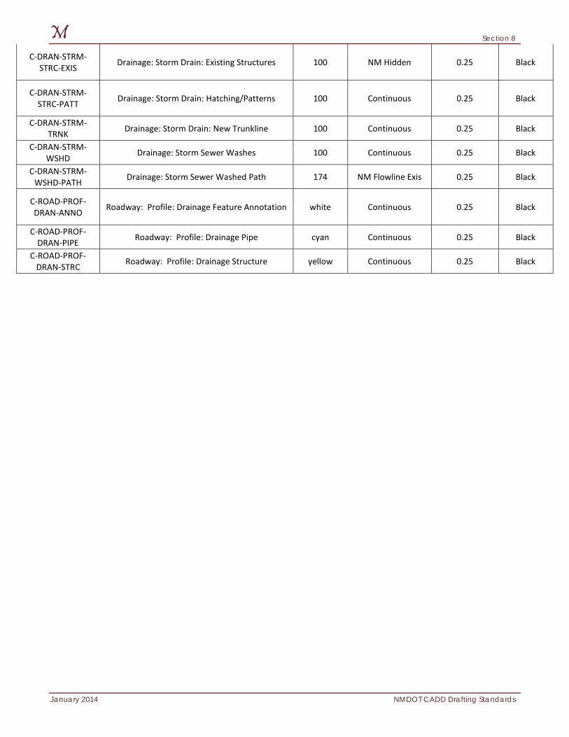
Section 8
January 2014 NMDOT CADD Drafting Standards
C-DRAN-STRM-STRC-EXIS Drainage: Storm Drain: Existing Structures 100 NM Hidden 0.25 Black
C-DRAN-STRM-STRC-PATT Drainage: Storm Drain: Hatching/Patterns 100 Continuous 0.25 Black
C-DRAN-STRM-TRNK Drainage: Storm Drain: New Trunkline 100 Continuous 0.25 Black
C-DRAN-STRM-WSHD Drainage: Storm Sewer Washes 100 Continuous 0.25 Black
C-DRAN-STRM-WSHD-PATH Drainage: Storm Sewer Washed Path 174 NM Flowline Exis 0.25 Black
C-ROAD-PROF-DRAN-ANNO Roadway: Profile: Drainage Feature Annotation white Continuous 0.25 Black
C-ROAD-PROF-DRAN-PIPE Roadway: Profile: Drainage Pipe cyan Continuous 0.25 Black
C-ROAD-PROF-DRAN-STRC Roadway: Profile: Drainage Structure yellow Continuous 0.25 Black
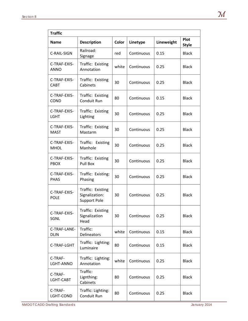
Section 8
NMDOT CADD Drafting Standards January 2014
Traffic
Name Description Color Linetype Lineweight Plot Style
C-RAIL-SIGN Railroad: Signage red Continuous 0.15 Black
C-TRAF-EXIS-ANNO
Traffic: Existing Annotation white Continuous 0.25 Black
C-TRAF-EXIS-CABT
Traffic: Existing Cabinets 30 Continuous 0.25 Black
C-TRAF-EXIS-COND
Traffic: Existing Conduit Run 80 Continuous 0.15 Black
C-TRAF-EXIS-LGHT
Traffic: Existing Lighting 30 Continuous 0.25 Black
C-TRAF-EXIS-MAST
Traffic: Existing Mastarm 30 Continuous 0.25 Black
C-TRAF-EXIS-MHOL
Traffic: Existing Manhole 30 Continuous 0.25 Black
C-TRAF-EXIS-PBOX
Traffic: Existing Pull Box 30 Continuous 0.25 Black
C-TRAF-EXIS-PHAS
Traffic: Existing: Phasing 30 Continuous 0.25 Black
C-TRAF-EXIS-POLE
Traffic: Existing Signalization: Support Pole
30 Continuous 0.25 Black
C-TRAF-EXIS-SGNL
Traffic: Existing Signalization Head
30 Continuous 0.25 Black
C-TRAF-LANE-DLIN
Traffic: Delineators white Continuous 0.15 Black
C-TRAF-LGHT Traffic: Lighting: Luminaire 80 Continuous 0.15 Black
C-TRAF-LGHT-ANNO
Traffic: Lighting: Annotation white Continuous 0.25 Black
C-TRAF-LGHT-CABT
Traffic: Lignthing: Cabinets
80 Continuous 0.25 Black
C-TRAF-LGHT-COND
Traffic: Lighting: Conduit Run 80 Continuous 0.25 Black
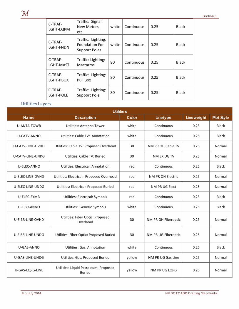
Section 8
January 2014 NMDOT CADD Drafting Standards
C-TRAF-LGHT-EQPM
Traffic: Signal: New Meters, etc.
white Continuous 0.25 Black
C-TRAF-LGHT-FNDN
Traffic: Lighting: Foundation For Support Poles
white Continuous 0.25 Black
C-TRAF-LGHT-MAST
Traffic: Lighting: Mastarms 80 Continuous 0.25 Black
C-TRAF-LGHT-PBOX
Traffic: Lighting: Pull Box 80 Continuous 0.25 Black
C-TRAF-LGHT-POLE
Traffic: Lighting: Support Pole 80 Continuous 0.25 Black
Utilities Layers Utilities
Name Description Color Linetype Lineweight Plot Style
U-ANTA-TOWR Utilities: Antenna Tower white Continuous 0.25 Black
U-CATV-ANNO Utilities: Cable TV: Annotation white Continuous 0.25 Black
U-CATV-LINE-OVHD Utilities: Cable TV: Proposed Overhead 30 NM PR OH Cable TV 0.25 Normal
U-CATV-LINE-UNDG Utilities: Cable TV: Buried 30 NM EX UG TV 0.25 Normal
U-ELEC-ANNO Utilities: Electrical: Annotation red Continuous 0.25 Black
U-ELEC-LINE-OVHD Utilities: Electrical: Proposed Overhead red NM PR OH Electric 0.25 Normal
U-ELEC-LINE-UNDG Utilities: Electrical: Proposed Buried red NM PR UG Elect 0.25 Normal
U-ELEC-SYMB Utilities: Electrical: Symbols red Continuous 0.25 Black
U-FIBR-ANNO Utilities: Generic Symbols white Continuous 0.25 Black
U-FIBR-LINE-OVHD Utilities: Fiber Optic: Proposed Overhead 30 NM PR OH Fiberoptic 0.25 Normal
U-FIBR-LINE-UNDG Utilities: Fiber Optic: Proposed Buried 30 NM PR UG Fiberoptic 0.25 Normal
U-GAS-ANNO Utilities: Gas: Annotation white Continuous 0.25 Black
U-GAS-LINE-UNDG Utilities: Gas: Proposed Buried yellow NM PR UG Gas Line 0.25 Normal
U-GAS-LQPG-LINE Utilities: Liquid Petroleum: Proposed Buried yellow NM PR UG LQPG 0.25 Normal
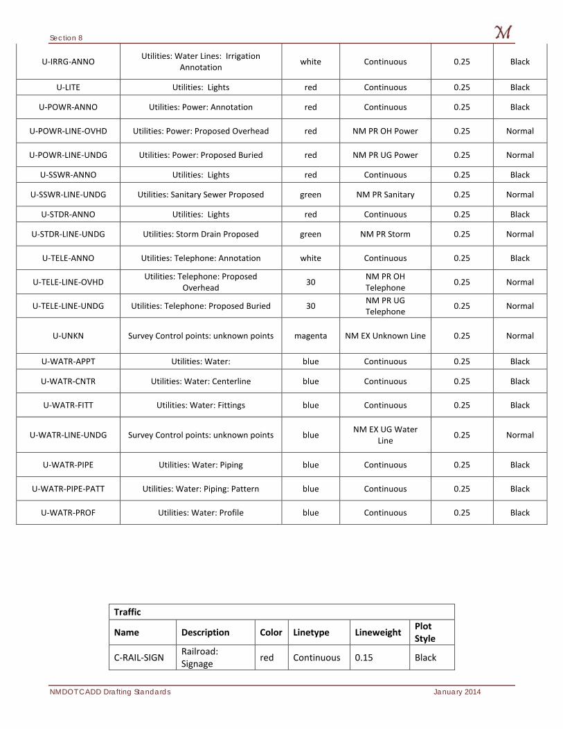
Section 8
NMDOT CADD Drafting Standards January 2014
U-IRRG-ANNO Utilities: Water Lines: Irrigation Annotation white Continuous 0.25 Black
U-LITE Utilities: Lights red Continuous 0.25 Black
U-POWR-ANNO Utilities: Power: Annotation red Continuous 0.25 Black
U-POWR-LINE-OVHD Utilities: Power: Proposed Overhead red NM PR OH Power 0.25 Normal
U-POWR-LINE-UNDG Utilities: Power: Proposed Buried red NM PR UG Power 0.25 Normal
U-SSWR-ANNO Utilities: Lights red Continuous 0.25 Black
U-SSWR-LINE-UNDG Utilities: Sanitary Sewer Proposed green NM PR Sanitary 0.25 Normal
U-STDR-ANNO Utilities: Lights red Continuous 0.25 Black
U-STDR-LINE-UNDG Utilities: Storm Drain Proposed green NM PR Storm 0.25 Normal
U-TELE-ANNO Utilities: Telephone: Annotation white Continuous 0.25 Black
U-TELE-LINE-OVHD Utilities: Telephone: Proposed Overhead 30 NM PR OH
Telephone 0.25 Normal
U-TELE-LINE-UNDG Utilities: Telephone: Proposed Buried 30 NM PR UG Telephone 0.25 Normal
U-UNKN Survey Control points: unknown points magenta NM EX Unknown Line 0.25 Normal
U-WATR-APPT Utilities: Water: blue Continuous 0.25 Black
U-WATR-CNTR Utilities: Water: Centerline blue Continuous 0.25 Black
U-WATR-FITT Utilities: Water: Fittings blue Continuous 0.25 Black
U-WATR-LINE-UNDG Survey Control points: unknown points blue NM EX UG Water Line 0.25 Normal
U-WATR-PIPE Utilities: Water: Piping blue Continuous 0.25 Black
U-WATR-PIPE-PATT Utilities: Water: Piping: Pattern blue Continuous 0.25 Black
U-WATR-PROF Utilities: Water: Profile blue Continuous 0.25 Black
Traffic
Name Description Color Linetype Lineweight Plot Style
C-RAIL-SIGN Railroad: Signage red Continuous 0.15 Black
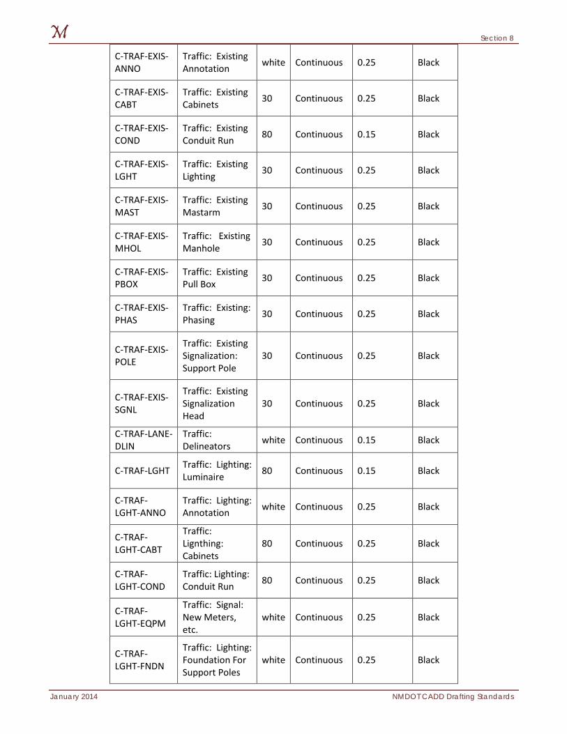
Section 8
January 2014 NMDOT CADD Drafting Standards
C-TRAF-EXIS-ANNO
Traffic: Existing Annotation white Continuous 0.25 Black
C-TRAF-EXIS-CABT
Traffic: Existing Cabinets 30 Continuous 0.25 Black
C-TRAF-EXIS-COND
Traffic: Existing Conduit Run 80 Continuous 0.15 Black
C-TRAF-EXIS-LGHT
Traffic: Existing Lighting 30 Continuous 0.25 Black
C-TRAF-EXIS-MAST
Traffic: Existing Mastarm 30 Continuous 0.25 Black
C-TRAF-EXIS-MHOL
Traffic: Existing Manhole 30 Continuous 0.25 Black
C-TRAF-EXIS-PBOX
Traffic: Existing Pull Box 30 Continuous 0.25 Black
C-TRAF-EXIS-PHAS
Traffic: Existing: Phasing 30 Continuous 0.25 Black
C-TRAF-EXIS-POLE
Traffic: Existing Signalization: Support Pole
30 Continuous 0.25 Black
C-TRAF-EXIS-SGNL
Traffic: Existing Signalization Head
30 Continuous 0.25 Black
C-TRAF-LANE-DLIN
Traffic: Delineators white Continuous 0.15 Black
C-TRAF-LGHT Traffic: Lighting: Luminaire 80 Continuous 0.15 Black
C-TRAF-LGHT-ANNO
Traffic: Lighting: Annotation white Continuous 0.25 Black
C-TRAF-LGHT-CABT
Traffic: Lignthing: Cabinets
80 Continuous 0.25 Black
C-TRAF-LGHT-COND
Traffic: Lighting: Conduit Run 80 Continuous 0.25 Black
C-TRAF-LGHT-EQPM
Traffic: Signal: New Meters, etc.
white Continuous 0.25 Black
C-TRAF-LGHT-FNDN
Traffic: Lighting: Foundation For Support Poles
white Continuous 0.25 Black
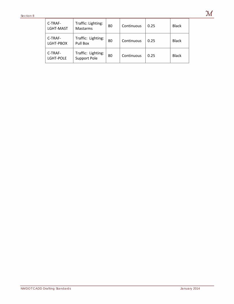
Section 8
NMDOT CADD Drafting Standards January 2014
C-TRAF-LGHT-MAST
Traffic: Lighting: Mastarms 80 Continuous 0.25 Black
C-TRAF-LGHT-PBOX
Traffic: Lighting: Pull Box 80 Continuous 0.25 Black
C-TRAF-LGHT-POLE
Traffic: Lighting: Support Pole 80 Continuous 0.25 Black
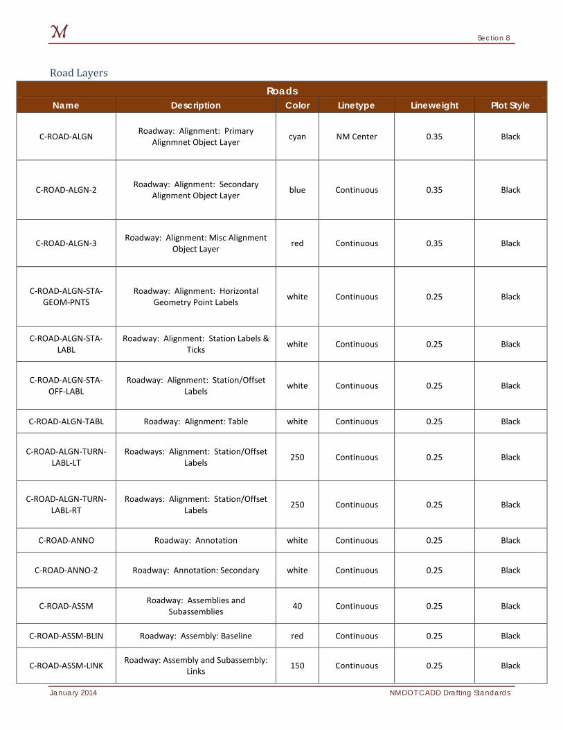
Section 8
January 2014 NMDOT CADD Drafting Standards
Road Layers Roads
Name Description Color Linetype Lineweight Plot Style
C-ROAD-ALGN Roadway: Alignment: Primary Alignmnet Object Layer cyan NM Center 0.35 Black
C-ROAD-ALGN-2 Roadway: Alignment: Secondary Alignment Object Layer blue Continuous 0.35 Black
C-ROAD-ALGN-3 Roadway: Alignment: Misc Alignment Object Layer red Continuous 0.35 Black
C-ROAD-ALGN-STA-GEOM-PNTS
Roadway: Alignment: Horizontal Geometry Point Labels white Continuous 0.25 Black
C-ROAD-ALGN-STA-LABL
Roadway: Alignment: Station Labels & Ticks white Continuous 0.25 Black
C-ROAD-ALGN-STA-OFF-LABL
Roadway: Alignment: Station/Offset Labels white Continuous 0.25 Black
C-ROAD-ALGN-TABL Roadway: Alignment: Table white Continuous 0.25 Black
C-ROAD-ALGN-TURN-LABL-LT
Roadways: Alignment: Station/Offset Labels 250 Continuous 0.25 Black
C-ROAD-ALGN-TURN-LABL-RT
Roadways: Alignment: Station/Offset Labels 250 Continuous 0.25 Black
C-ROAD-ANNO Roadway: Annotation white Continuous 0.25 Black
C-ROAD-ANNO-2 Roadway: Annotation: Secondary white Continuous 0.25 Black
C-ROAD-ASSM Roadway: Assemblies and Subassemblies 40 Continuous 0.25 Black
C-ROAD-ASSM-BLIN Roadway: Assembly: Baseline red Continuous 0.25 Black
C-ROAD-ASSM-LINK Roadway: Assembly and Subassembly: Links 150 Continuous 0.25 Black
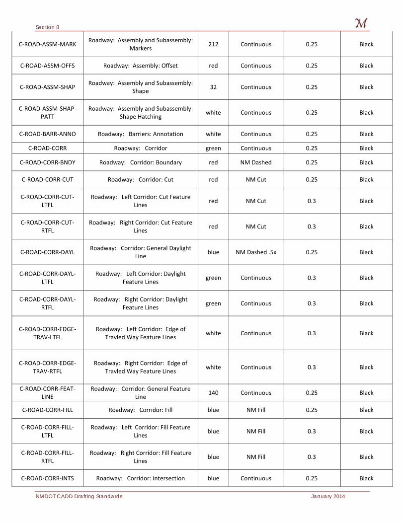
Section 8
NMDOT CADD Drafting Standards January 2014
C-ROAD-ASSM-MARK Roadway: Assembly and Subassembly: Markers 212 Continuous 0.25 Black
C-ROAD-ASSM-OFFS Roadway: Assembly: Offset red Continuous 0.25 Black
C-ROAD-ASSM-SHAP Roadway: Assembly and Subassembly: Shape 32 Continuous 0.25 Black
C-ROAD-ASSM-SHAP-PATT
Roadway: Assembly and Subassembly: Shape Hatching white Continuous 0.25 Black
C-ROAD-BARR-ANNO Roadway: Barriers: Annotation white Continuous 0.25 Black
C-ROAD-CORR Roadway: Corridor green Continuous 0.25 Black
C-ROAD-CORR-BNDY Roadway: Corridor: Boundary red NM Dashed 0.25 Black
C-ROAD-CORR-CUT Roadway: Corridor: Cut red NM Cut 0.25 Black
C-ROAD-CORR-CUT-LTFL
Roadway: Left Corridor: Cut Feature Lines red NM Cut 0.3 Black
C-ROAD-CORR-CUT-RTFL
Roadway: Right Corridor: Cut Feature Lines red NM Cut 0.3 Black
C-ROAD-CORR-DAYL Roadway: Corridor: General Daylight Line blue NM Dashed .5x 0.25 Black
C-ROAD-CORR-DAYL-LTFL
Roadway: Left Corridor: Daylight Feature Lines green Continuous 0.3 Black
C-ROAD-CORR-DAYL-RTFL
Roadway: Right Corridor: Daylight Feature Lines green Continuous 0.3 Black
C-ROAD-CORR-EDGE-TRAV-LTFL
Roadway: Left Corridor: Edge of Travled Way Feature Lines white Continuous 0.3 Black
C-ROAD-CORR-EDGE-TRAV-RTFL
Roadway: Right Corridor: Edge of Travled Way Feature Lines white Continuous 0.3 Black
C-ROAD-CORR-FEAT-LINE
Roadway: Corridor: General Feature Line 140 Continuous 0.25 Black
C-ROAD-CORR-FILL Roadway: Corridor: Fill blue NM Fill 0.25 Black
C-ROAD-CORR-FILL-LTFL
Roadway: Left Corridor: Fill Feature Lines blue NM Fill 0.3 Black
C-ROAD-CORR-FILL-RTFL
Roadway: Right Corridor: Fill Feature Lines blue NM Fill 0.3 Black
C-ROAD-CORR-INTS Roadway: Corridor: Intersection blue Continuous 0.25 Black
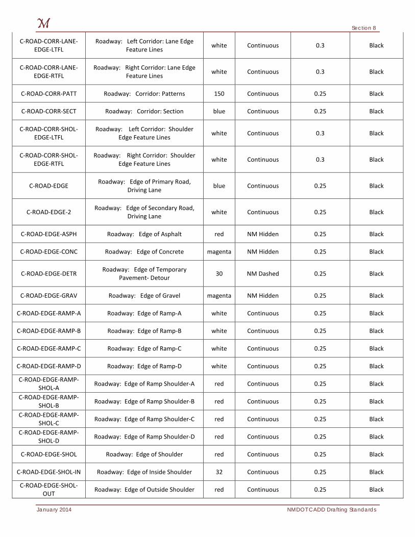
Section 8
January 2014 NMDOT CADD Drafting Standards
C-ROAD-CORR-LANE-EDGE-LTFL
Roadway: Left Corridor: Lane Edge Feature Lines white Continuous 0.3 Black
C-ROAD-CORR-LANE-EDGE-RTFL
Roadway: Right Corridor: Lane Edge Feature Lines white Continuous 0.3 Black
C-ROAD-CORR-PATT Roadway: Corridor: Patterns 150 Continuous 0.25 Black
C-ROAD-CORR-SECT Roadway: Corridor: Section blue Continuous 0.25 Black
C-ROAD-CORR-SHOL-EDGE-LTFL
Roadway: Left Corridor: Shoulder Edge Feature Lines white Continuous 0.3 Black
C-ROAD-CORR-SHOL-EDGE-RTFL
Roadway: Right Corridor: Shoulder Edge Feature Lines white Continuous 0.3 Black
C-ROAD-EDGE Roadway: Edge of Primary Road, Driving Lane blue Continuous 0.25 Black
C-ROAD-EDGE-2 Roadway: Edge of Secondary Road, Driving Lane white Continuous 0.25 Black
C-ROAD-EDGE-ASPH Roadway: Edge of Asphalt red NM Hidden 0.25 Black
C-ROAD-EDGE-CONC Roadway: Edge of Concrete magenta NM Hidden 0.25 Black
C-ROAD-EDGE-DETR Roadway: Edge of Temporary Pavement- Detour 30 NM Dashed 0.25 Black
C-ROAD-EDGE-GRAV Roadway: Edge of Gravel magenta NM Hidden 0.25 Black
C-ROAD-EDGE-RAMP-A Roadway: Edge of Ramp-A white Continuous 0.25 Black
C-ROAD-EDGE-RAMP-B Roadway: Edge of Ramp-B white Continuous 0.25 Black
C-ROAD-EDGE-RAMP-C Roadway: Edge of Ramp-C white Continuous 0.25 Black
C-ROAD-EDGE-RAMP-D Roadway: Edge of Ramp-D white Continuous 0.25 Black
C-ROAD-EDGE-RAMP-SHOL-A Roadway: Edge of Ramp Shoulder-A red Continuous 0.25 Black
C-ROAD-EDGE-RAMP-SHOL-B Roadway: Edge of Ramp Shoulder-B red Continuous 0.25 Black
C-ROAD-EDGE-RAMP-SHOL-C Roadway: Edge of Ramp Shoulder-C red Continuous 0.25 Black
C-ROAD-EDGE-RAMP-SHOL-D Roadway: Edge of Ramp Shoulder-D red Continuous 0.25 Black
C-ROAD-EDGE-SHOL Roadway: Edge of Shoulder red Continuous 0.25 Black
C-ROAD-EDGE-SHOL-IN Roadway: Edge of Inside Shoulder 32 Continuous 0.25 Black
C-ROAD-EDGE-SHOL-OUT Roadway: Edge of Outside Shoulder red Continuous 0.25 Black
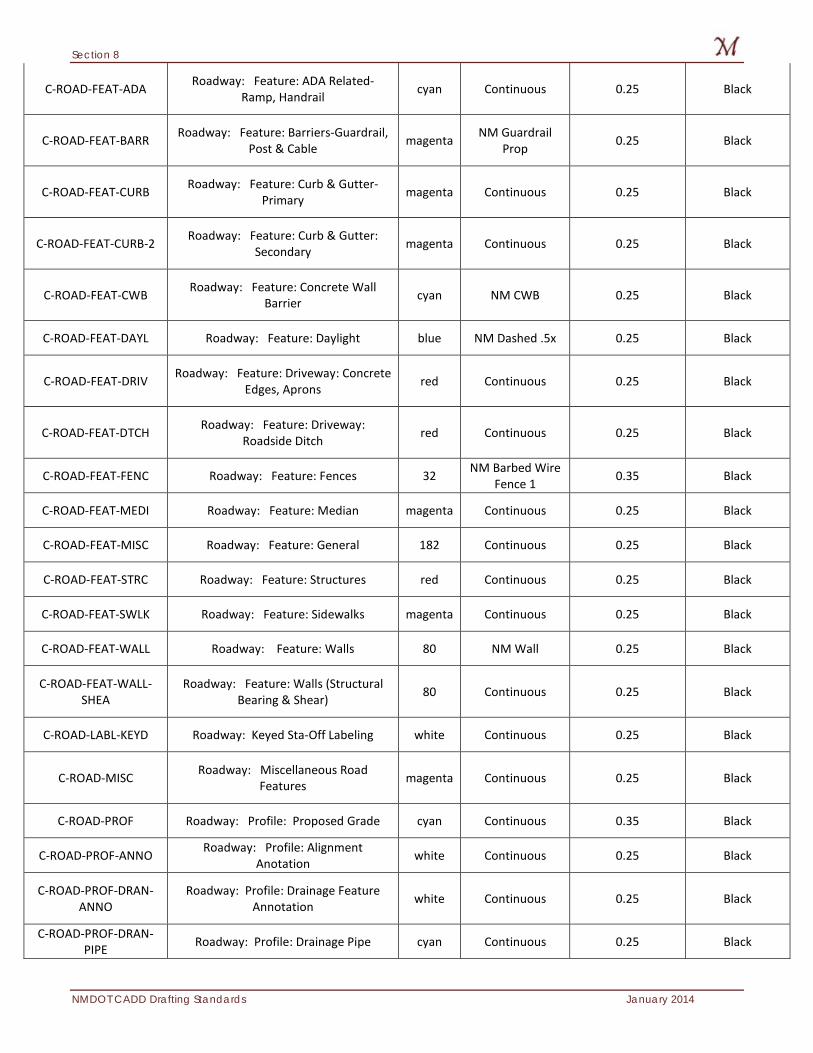
Section 8
NMDOT CADD Drafting Standards January 2014
C-ROAD-FEAT-ADA Roadway: Feature: ADA Related-Ramp, Handrail cyan Continuous 0.25 Black
C-ROAD-FEAT-BARR Roadway: Feature: Barriers-Guardrail, Post & Cable magenta NM Guardrail
Prop 0.25 Black
C-ROAD-FEAT-CURB Roadway: Feature: Curb & Gutter-Primary magenta Continuous 0.25 Black
C-ROAD-FEAT-CURB-2 Roadway: Feature: Curb & Gutter: Secondary magenta Continuous 0.25 Black
C-ROAD-FEAT-CWB Roadway: Feature: Concrete Wall Barrier cyan NM CWB 0.25 Black
C-ROAD-FEAT-DAYL Roadway: Feature: Daylight blue NM Dashed .5x 0.25 Black
C-ROAD-FEAT-DRIV Roadway: Feature: Driveway: Concrete Edges, Aprons red Continuous 0.25 Black
C-ROAD-FEAT-DTCH Roadway: Feature: Driveway: Roadside Ditch red Continuous 0.25 Black
C-ROAD-FEAT-FENC Roadway: Feature: Fences 32 NM Barbed Wire Fence 1 0.35 Black
C-ROAD-FEAT-MEDI Roadway: Feature: Median magenta Continuous 0.25 Black
C-ROAD-FEAT-MISC Roadway: Feature: General 182 Continuous 0.25 Black
C-ROAD-FEAT-STRC Roadway: Feature: Structures red Continuous 0.25 Black
C-ROAD-FEAT-SWLK Roadway: Feature: Sidewalks magenta Continuous 0.25 Black
C-ROAD-FEAT-WALL Roadway: Feature: Walls 80 NM Wall 0.25 Black
C-ROAD-FEAT-WALL-SHEA
Roadway: Feature: Walls (Structural Bearing & Shear) 80 Continuous 0.25 Black
C-ROAD-LABL-KEYD Roadway: Keyed Sta-Off Labeling white Continuous 0.25 Black
C-ROAD-MISC Roadway: Miscellaneous Road Features magenta Continuous 0.25 Black
C-ROAD-PROF Roadway: Profile: Proposed Grade cyan Continuous 0.35 Black
C-ROAD-PROF-ANNO Roadway: Profile: Alignment Anotation white Continuous 0.25 Black
C-ROAD-PROF-DRAN-ANNO
Roadway: Profile: Drainage Feature Annotation white Continuous 0.25 Black
C-ROAD-PROF-DRAN-PIPE Roadway: Profile: Drainage Pipe cyan Continuous 0.25 Black
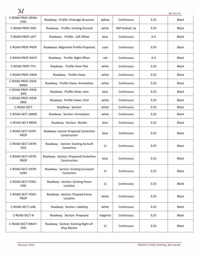
Section 8
January 2014 NMDOT CADD Drafting Standards
C-ROAD-PROF-DRAN-STRC Roadway: Profile: Drainage Structure yellow Continuous 0.25 Black
C-ROAD-PROF-EXIS Roadway: Profile: Existing Ground white NM Dashed .5x 0.25 Black
C-ROAD-PROF-LEFT Roadway: Profile: Left Offset blue Continuous 0.3 Black
C-ROAD-PROF-PROP Roadways: Alignment Profile Proposed cyan Continuous 0.35 Black
C-ROAD-PROF-RGHT Roadway: Profile: Right Offset red Continuous 0.3 Black
C-ROAD-PROF-TITL Roadway: Profile View Title white Continuous 0.25 Black
C-ROAD-PROF-VIEW Roadway: Profile Views white Continuous 0.25 Black
C-ROAD-PROF-VIEW-ANNO Roadway: Profile Views: Annotation white Continuous 0.25 Black
C-ROAD-PROF-VIEW-AXIS Roadway: Profile Views: Axis blue Continuous 0.25 Black
C-ROAD-PROF-VIEW-GRID Roadway: Profile Views: Grid white Continuous 0.25 Black
C-ROAD-SECT Roadway: Section white Continuous 0.25 Black
C-ROAD-SECT-ANNO Roadway: Section: Annotation white Continuous 0.25 Black
C-ROAD-SECT-BRDR Roadway: Section: Border blue Continuous 0.25 Black
C-ROAD-SECT-CENT-PROP
Roadway: section Proposed Centerline Construction blue Continuous 0.25 Black
C-ROAD-SECT-CNTR-EXIS
Roadway: Section: Exisitng As-built Centerline 11 Continuous 0.25 Black
C-ROAD-SECT-CNTR-PROP
Roadway: Section: Proposed Centerline Construction blue Continuous 0.25 Black
C-ROAD-SECT-CNTR-SURV
Roadway: Section: Existing Surveyed Centerline 11 Continuous 0.25 Black
C-ROAD-SECT-FENC-EXIS
Roadway: Section: Exisitng Fence Location 11 Continuous 0.25 Black
C-ROAD-SECT-FENC-PROP
Roadway: Section: Propsed Fence Location white Continuous 0.25 Black
C-ROAD-SECT-LABL Roadway: Section: Labeling white Continuous 0.25 Black
C-ROAD-SECT-N Roadway: Section: Proposed magenta Continuous 0.25 Black
C-ROAD-SECT-RWAY-EXIS
Roadway: Section: Exisitng Right-of-Way Marker 11 Continuous 0.25 Black
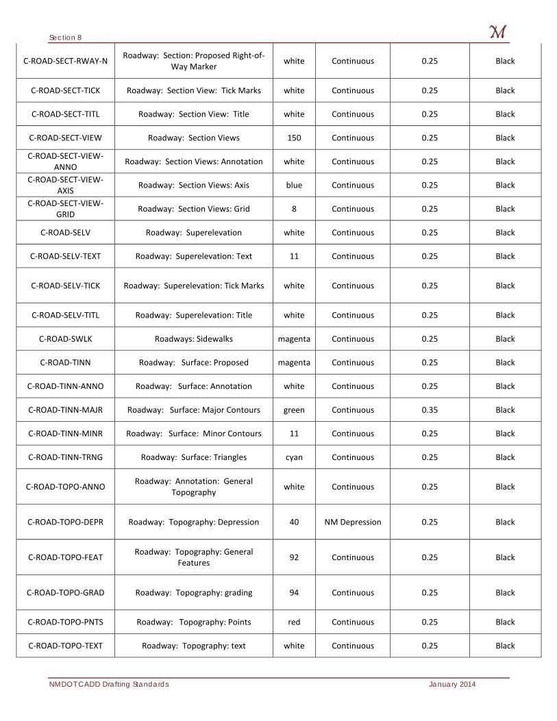
Section 8
NMDOT CADD Drafting Standards January 2014
C-ROAD-SECT-RWAY-N Roadway: Section: Proposed Right-of-Way Marker white Continuous 0.25 Black
C-ROAD-SECT-TICK Roadway: Section View: Tick Marks white Continuous 0.25 Black
C-ROAD-SECT-TITL Roadway: Section View: Title white Continuous 0.25 Black
C-ROAD-SECT-VIEW Roadway: Section Views 150 Continuous 0.25 Black
C-ROAD-SECT-VIEW-ANNO Roadway: Section Views: Annotation white Continuous 0.25 Black
C-ROAD-SECT-VIEW-AXIS Roadway: Section Views: Axis blue Continuous 0.25 Black
C-ROAD-SECT-VIEW-GRID Roadway: Section Views: Grid 8 Continuous 0.25 Black
C-ROAD-SELV Roadway: Superelevation white Continuous 0.25 Black
C-ROAD-SELV-TEXT Roadway: Superelevation: Text 11 Continuous 0.25 Black
C-ROAD-SELV-TICK Roadway: Superelevation: Tick Marks white Continuous 0.25 Black
C-ROAD-SELV-TITL Roadway: Superelevation: Title white Continuous 0.25 Black
C-ROAD-SWLK Roadways: Sidewalks magenta Continuous 0.25 Black
C-ROAD-TINN Roadway: Surface: Proposed magenta Continuous 0.25 Black
C-ROAD-TINN-ANNO Roadway: Surface: Annotation white Continuous 0.25 Black
C-ROAD-TINN-MAJR Roadway: Surface: Major Contours green Continuous 0.35 Black
C-ROAD-TINN-MINR Roadway: Surface: Minor Contours 11 Continuous 0.25 Black
C-ROAD-TINN-TRNG Roadway: Surface: Triangles cyan Continuous 0.25 Black
C-ROAD-TOPO-ANNO Roadway: Annotation: General Topography white Continuous 0.25 Black
C-ROAD-TOPO-DEPR Roadway: Topography: Depression 40 NM Depression 0.25 Black
C-ROAD-TOPO-FEAT Roadway: Topography: General Features 92 Continuous 0.25 Black
C-ROAD-TOPO-GRAD Roadway: Topography: grading 94 Continuous 0.25 Black
C-ROAD-TOPO-PNTS Roadway: Topography: Points red Continuous 0.25 Black
C-ROAD-TOPO-TEXT Roadway: Topography: text white Continuous 0.25 Black
Section 8
January 2014 NMDOT CADD Drafting Standards
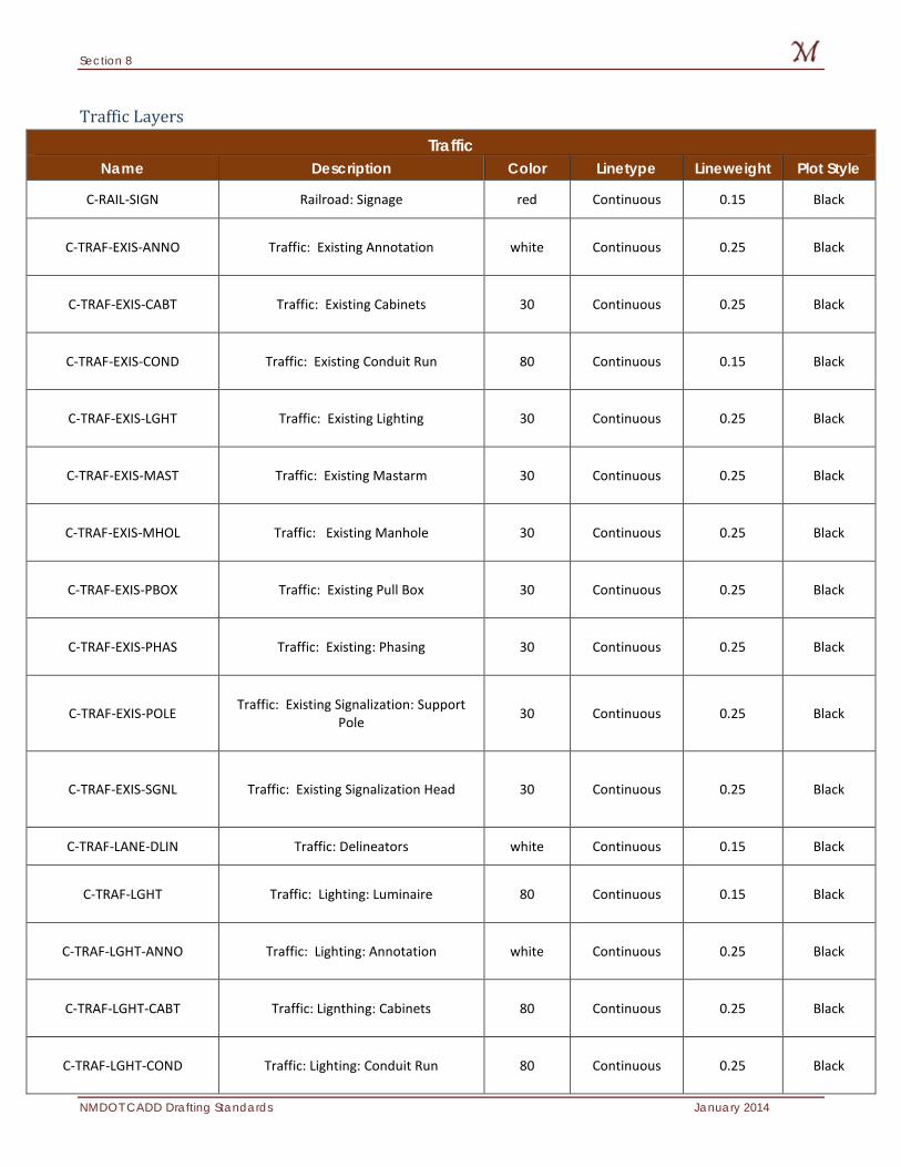
Section 8
NMDOT CADD Drafting Standards January 2014
Traffic Layers Traffic
Name Description Color Linetype Lineweight Plot Style
C-RAIL-SIGN Railroad: Signage red Continuous 0.15 Black
C-TRAF-EXIS-ANNO Traffic: Existing Annotation white Continuous 0.25 Black
C-TRAF-EXIS-CABT Traffic: Existing Cabinets 30 Continuous 0.25 Black
C-TRAF-EXIS-COND Traffic: Existing Conduit Run 80 Continuous 0.15 Black
C-TRAF-EXIS-LGHT Traffic: Existing Lighting 30 Continuous 0.25 Black
C-TRAF-EXIS-MAST Traffic: Existing Mastarm 30 Continuous 0.25 Black
C-TRAF-EXIS-MHOL Traffic: Existing Manhole 30 Continuous 0.25 Black
C-TRAF-EXIS-PBOX Traffic: Existing Pull Box 30 Continuous 0.25 Black
C-TRAF-EXIS-PHAS Traffic: Existing: Phasing 30 Continuous 0.25 Black
C-TRAF-EXIS-POLE Traffic: Existing Signalization: Support Pole 30 Continuous 0.25 Black
C-TRAF-EXIS-SGNL Traffic: Existing Signalization Head 30 Continuous 0.25 Black
C-TRAF-LANE-DLIN Traffic: Delineators white Continuous 0.15 Black
C-TRAF-LGHT Traffic: Lighting: Luminaire 80 Continuous 0.15 Black
C-TRAF-LGHT-ANNO Traffic: Lighting: Annotation white Continuous 0.25 Black
C-TRAF-LGHT-CABT Traffic: Lignthing: Cabinets 80 Continuous 0.25 Black
C-TRAF-LGHT-COND Traffic: Lighting: Conduit Run 80 Continuous 0.25 Black
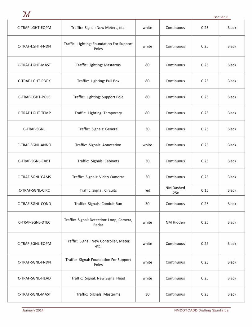
Section 8
January 2014 NMDOT CADD Drafting Standards
C-TRAF-LGHT-EQPM Traffic: Signal: New Meters, etc. white Continuous 0.25 Black
C-TRAF-LGHT-FNDN Traffic: Lighting: Foundation For Support Poles white Continuous 0.25 Black
C-TRAF-LGHT-MAST Traffic: Lighting: Mastarms 80 Continuous 0.25 Black
C-TRAF-LGHT-PBOX Traffic: Lighting: Pull Box 80 Continuous 0.25 Black
C-TRAF-LGHT-POLE Traffic: Lighting: Support Pole 80 Continuous 0.25 Black
C-TRAF-LGHT-TEMP Traffic: Lighting: Temporary 80 Continuous 0.25 Black
C-TRAF-SGNL Traffic: Signals: General 30 Continuous 0.25 Black
C-TRAF-SGNL-ANNO Traffic: Signals: Annotation white Continuous 0.25 Black
C-TRAF-SGNL-CABT Traffic: Signals: Cabinets 30 Continuous 0.25 Black
C-TRAF-SGNL-CAMS Traffic: Signals: Video Cameras 30 Continuous 0.25 Black
C-TRAF-SGNL-CIRC Traffic: Signal: Circuits red NM Dashed .25x 0.15 Black
C-TRAF-SGNL-COND Traffic: Signals: Conduit Run 30 Continuous 0.25 Black
C-TRAF-SGNL-DTEC Traffic: Signal: Detection: Loop, Camera, Radar white NM Hidden 0.25 Black
C-TRAF-SGNL-EQPM Traffic: Signal: New Controller, Meter, etc. white Continuous 0.25 Black
C-TRAF-SGNL-FNDN Traffic: Signal: Foundation For Support Poles white Continuous 0.25 Black
C-TRAF-SGNL-HEAD Traffic: Signal: New Signal Head white Continuous 0.25 Black
C-TRAF-SGNL-MAST Traffic: Signals: Mastarms 30 Continuous 0.25 Black
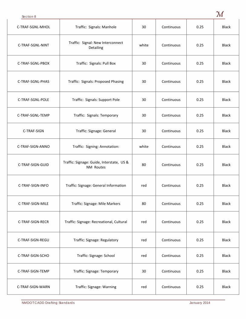
Section 8
NMDOT CADD Drafting Standards January 2014
C-TRAF-SGNL-MHOL Traffic: Signals: Manhole 30 Continuous 0.25 Black
C-TRAF-SGNL-NINT Traffic: Signal: New Interconnect Detailing white Continuous 0.25 Black
C-TRAF-SGNL-PBOX Traffic: Signals: Pull Box 30 Continuous 0.25 Black
C-TRAF-SGNL-PHAS Traffic: Signals: Proposed Phasing 30 Continuous 0.25 Black
C-TRAF-SGNL-POLE Traffic: Signals: Support Pole 30 Continuous 0.25 Black
C-TRAF-SGNL-TEMP Traffic: Signals: Temporary 30 Continuous 0.25 Black
C-TRAF-SIGN Traffic: Signage: General 30 Continuous 0.25 Black
C-TRAF-SIGN-ANNO Traffic: Signing: Annotation: white Continuous 0.25 Black
C-TRAF-SIGN-GUID Traffic: Signage: Guide, Interstate, US & NM Routes 80 Continuous 0.25 Black
C-TRAF-SIGN-INFO Traffic: Signage: General Information red Continuous 0.25 Black
C-TRAF-SIGN-MILE Traffic: Signage: Mile Markers 80 Continuous 0.25 Black
C-TRAF-SIGN-RECR Traffic: Signage: Recreational, Cultural red Continuous 0.25 Black
C-TRAF-SIGN-REGU Traffic: Signage: Regulatory red Continuous 0.25 Black
C-TRAF-SIGN-SCHO Traffic: Signage: School red Continuous 0.25 Black
C-TRAF-SIGN-TEMP Traffic: Signage: Temporary 30 Continuous 0.25 Black
C-TRAF-SIGN-WARN Traffic: Signage: Warning red Continuous 0.25 Black
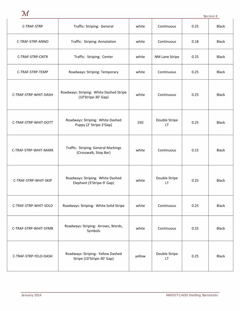
Section 8
January 2014 NMDOT CADD Drafting Standards
C-TRAF-STRP Traffic: Striping: General white Continuous 0.25 Black
C-TRAF-STRP-ANNO Traffic: Striping: Annotation white Continuous 0.18 Black
C-TRAF-STRP-CNTR Traffic: Striping: Center white NM Lane Stripe 0.25 Black
C-TRAF-STRP-TEMP Roadways: Striping: Temporary white Continuous 0.25 Black
C-TRAF-STRP-WHIT-DASH Roadways: Striping: White Dashed Stripe (10'Stripe-30' Gap) white Continuous 0.25 Black
C-TRAF-STRP-WHIT-DOTT Roadways: Striping: White Dashed Puppy (2' Stripe-2'Gap) 250 Double Stripe
LT 0.25 Black
C-TRAF-STRP-WHIT-MARK Traffic: Striping: General Markings (Crosswalk, Stop Bar) white Continuous 0.15 Black
C-TRAF-STRP-WHIT-SKIP Roadways: Striping: White Dashed Elephant (3'Stripe-9' Gap) white Double Stripe
LT 0.25 Black
C-TRAF-STRP-WHIT-SOLD Roadways: Striping: White Solid Stripe white Continuous 0.25 Black
C-TRAF-STRP-WHIT-SYMB Roadways: Striping: Arrows, Words, Symbols white Continuous 0.25 Black
C-TRAF-STRP-YELO-DASH Roadways: Striping: Yellow Dashed Stripe (10'Stripe-30' Gap) yellow Double Stripe
LT 0.25 Black
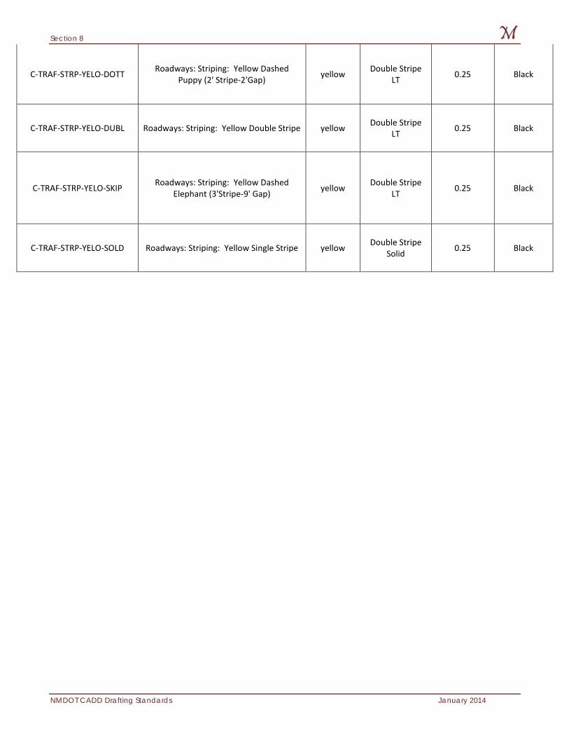
Section 8
NMDOT CADD Drafting Standards January 2014
C-TRAF-STRP-YELO-DOTT Roadways: Striping: Yellow Dashed Puppy (2' Stripe-2'Gap) yellow Double Stripe
LT 0.25 Black
C-TRAF-STRP-YELO-DUBL Roadways: Striping: Yellow Double Stripe yellow Double Stripe LT 0.25 Black
C-TRAF-STRP-YELO-SKIP Roadways: Striping: Yellow Dashed Elephant (3'Stripe-9' Gap) yellow Double Stripe
LT 0.25 Black
C-TRAF-STRP-YELO-SOLD Roadways: Striping: Yellow Single Stripe yellow Double Stripe Solid 0.25 Black
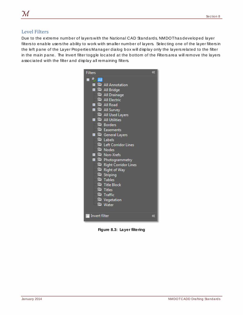
Section 8
January 2014 NMDOT CADD Drafting Standards
Level Filters Due to the extreme number of layers with the National CAD Standards, NMDOT has developed layer filters to enable users the ability to work with smaller number of layers. Selecting one of the layer filters in the left pane of the Layer Properties Manager dialog box will display only the layers related to the filter in the main pane. The Invert filter toggle located at the bottom of the Filters area will remove the layers associated with the filter and display all remaining filters.
Figure 8.3: Layer filtering

Section 9
January 2014 NMDOT CADD Drafting Standards
9: Symbology A CAD application’s settings of color, weight, and linetype are referred to as symbologies. It is possible to assign symbologies to either levels/layers, or to vector elements. The ByLevel/ByLayer setting has been the standard for NMDOT for several years and will continue to be the standard. This section discusses the different symbologies and resource file associated with each. Items discussed in this section:
Weights
Linetypes
Colors
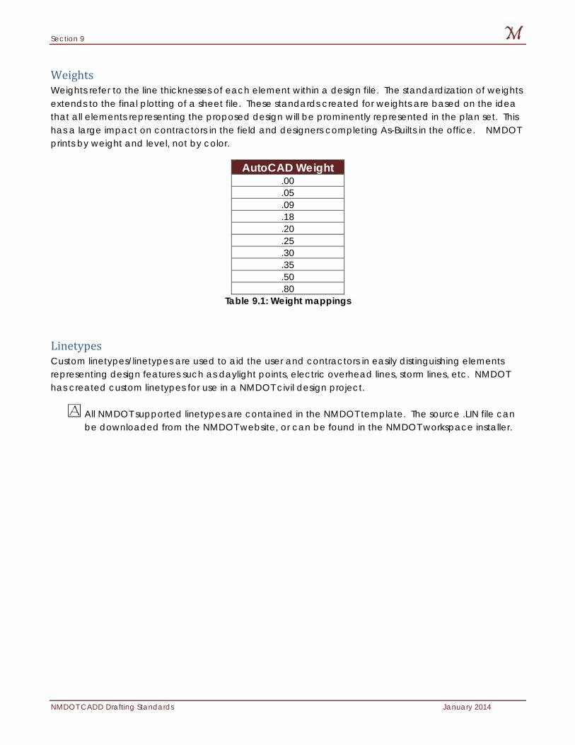
Section 9
NMDOT CADD Drafting Standards January 2014
Weights Weights refer to the line thicknesses of each element within a design file. The standardization of weights extends to the final plotting of a sheet file. These standards created for weights are based on the idea that all elements representing the proposed design will be prominently represented in the plan set. This has a large impact on contractors in the field and designers completing As-Builts in the office. NMDOT prints by weight and level, not by color.
AutoCAD Weight .00 .05 .09 .18 .20 .25 .30 .35 .50 .80
Table 9.1: Weight mappings
Linetypes Custom linetypes/linetypes are used to aid the user and contractors in easily distinguishing elements representing design features such as daylight points, electric overhead lines, storm lines, etc. NMDOT has created custom linetypes for use in a NMDOT civil design project.
All NMDOT supported linetypes are contained in the NMDOT template. The source .LIN file can be downloaded from the NMDOT website, or can be found in the NMDOT workspace installer.
Section 9
January 2014 NMDOT CADD Drafting Standards
Colors Every element in a CAD file has a color that is either assigned to the element, or assigned to the layer the element is placed on. Colors are very important in a CAD file as they allow for easy identification of elements, and types of elements. Because of both CAD platforms’ ability to plot by weight, NMDOT is able to assign colors to layers/elements that are somewhat logical (e.g. blue for water, red for electrical).
Gray Scaling and RGB values Gray scaling is a method used in a CAD file to “gray out”, or dither, a specified portion of the design to visually depress the boldness of the features. For example, this method is used to reference existing survey features, to “dull” their appearance visually on the screen, and to additionally invoke the plotting output to be “shaded”. This proves beneficial in diminishing the focus on the existing survey while enhancing the proposed design, allowing the designer to see existing and proposed features together on the same design plan sheet.
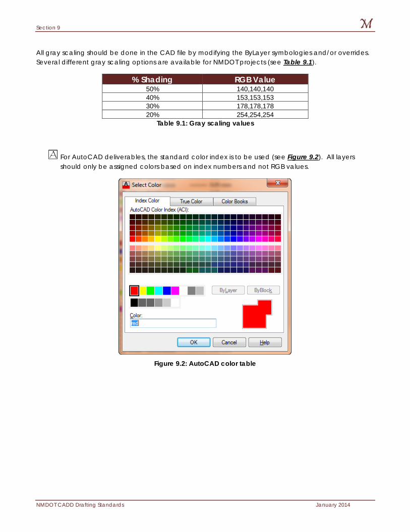
Section 9
NMDOT CADD Drafting Standards January 2014
All gray scaling should be done in the CAD file by modifying the ByLayer symbologies and/or overrides. Several different gray scaling options are available for NMDOT projects (see Table 9.1).
% Shading RGB Value 50% 140,140,140 40% 153,153,153 30% 178,178,178 20% 254,254,254
Table 9.1: Gray scaling values
For AutoCAD deliverables, the standard color index is to be used (see Figure 9.2). All layers should only be assigned colors based on index numbers and not RGB values.
Figure 9.2: AutoCAD color table
Section 10
January 2014 NMDOT CADD Drafting Standards
10: Annotation Annotation within AutoCAD has brought a greater flexibility and integration than previous versions. This added flexibility allows for AutoCAD shape files and Windows systems fonts to be fully integrated within the design environment. NMDOT has chosen to utilize Windows system fonts to be fully compatible between applications. This decision will allow for easy conversion between AutoCAD projects and MicroStation. Items discussed in this section:
NMDOT Standard Fonts
Text Sizes
Text Justification
Special Characters
Section 10
NMDOT CADD Drafting Standards January 2014
NMDOT Standard Fonts The NMDOT has standardized two primary fonts: Arial for survey and design text and Courier New for title block text. These font types are accessed from Windows System fonts and are represented below.
Existing Text Style = Arial
Proposed Text Style = Arial (with 20˚ slant)
Title Block Text Style = Courier New
Text Sizes The Annotation Scale tool for each CAD application allows for dynamic text sizing with minimal effort. This method allows for the development of sheets with multiple detail scales. The use of the Annotation Scale tool makes all text height calculations unnecessary.
The Annotation Scale tool determines the multiplication factor to be applied to all text and dimensions. The scale is applied by selecting the desired scale for each view port (see Section 6: Layouts).
Text Justification Text justification is described as the “anchor point” for a single text element or multi line text node. This justification is important to set for text placement and alignment. The NMDOT’s standard text justification is defined for single text strings to be Left-Center and for Multi Line text nodes to be Top-Left. This allows all single line text to align from the left and multi-line text such as general notes to align left and start from a Top start point.
The NMDOT’s standard title block text justification should be set within a data file as Center-Center justification. (See Text Fields within this section for additional information).
Special Characters Special characters are symbols used for specific design annotation not found in standard font libraries. These symbols represent annotation such as Centerline, Flow Line, etc.
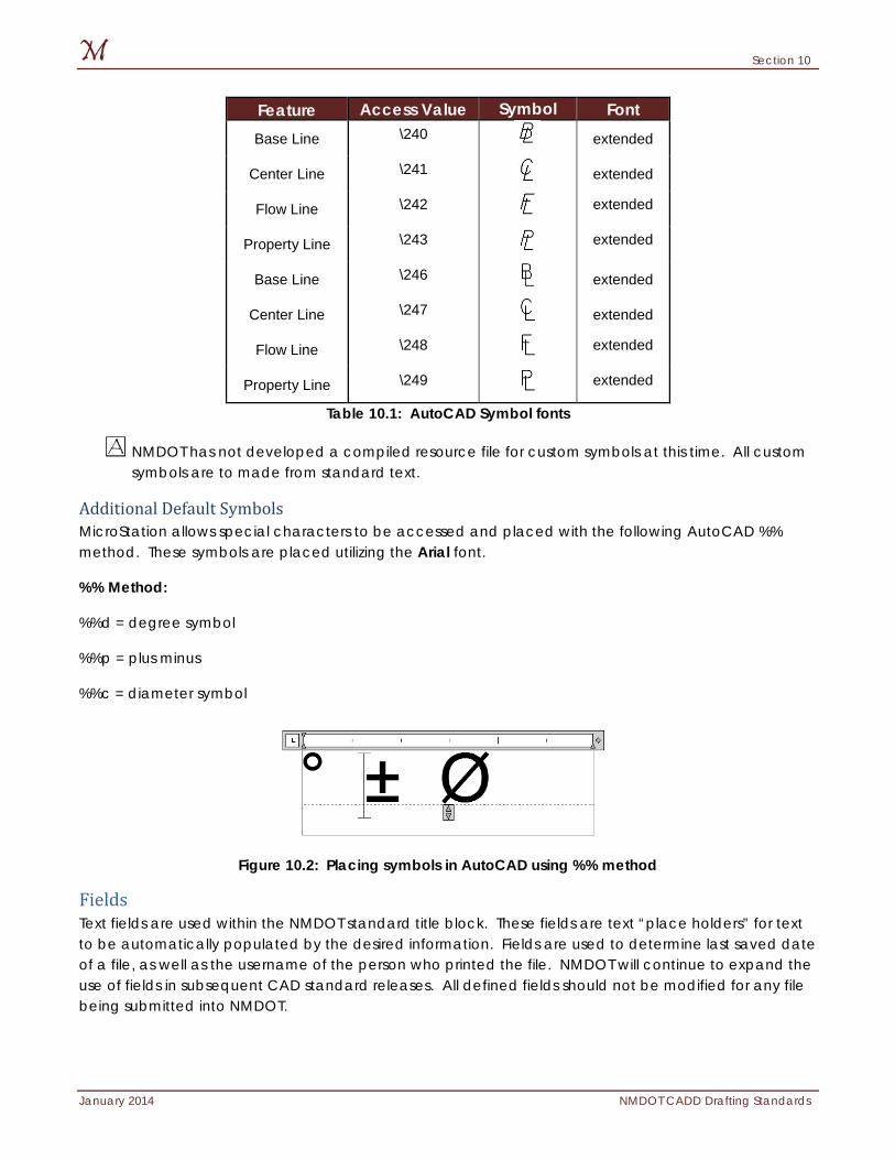
Section 10
January 2014 NMDOT CADD Drafting Standards
Feature Access Value Symbol Font Base Line \240 extended
Center Line \241 extended
Flow Line \242 extended
Property Line \243 extended
Base Line \246 extended
Center Line \247 extended
Flow Line \248 extended
Property Line \249 extended
Table 10.1: AutoCAD Symbol fonts
NMDOT has not developed a compiled resource file for custom symbols at this time. All custom symbols are to made from standard text.
Additional Default Symbols MicroStation allows special characters to be accessed and placed with the following AutoCAD %% method. These symbols are placed utilizing the Arial font.
%% Method:
%%d = degree symbol
%%p = plus minus
%%c = diameter symbol
Figure 10.2: Placing symbols in AutoCAD using %% method
Fields Text fields are used within the NMDOT standard title block. These fields are text “place holders” for text to be automatically populated by the desired information. Fields are used to determine last saved date of a file, as well as the username of the person who printed the file. NMDOT will continue to expand the use of fields in subsequent CAD standard releases. All defined fields should not be modified for any file being submitted into NMDOT.
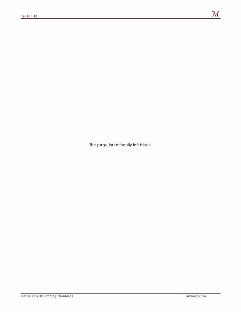
Section 10
NMDOT CADD Drafting Standards January 2014
The page intentionally left blank.
Section 11
January 2014 NMDOT CADD Drafting Standards
11: Cell Libraries/Blocks New Mexico Department of Transportation provides cell/block libraries for use in all of its civil designs. Cells/blocks are utilized in lieu of repeatedly drafting the same elements multiple times. The use of cells also aids in standardizing elements/details of NMDOT projects. Items discussed in this section:
Block Libraries
Block Attributes
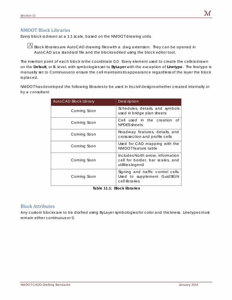
Section 11
NMDOT CADD Drafting Standards January 2014
NMDOT Block Libraries Every block is drawn at a 1:1 scale, based on the NMDOT drawing units.
Block libraries are AutoCAD drawing files with a .dwg extension. They can be opened in AutoCAD as a standard file and the blocks edited using the block editor tool.
The insertion point of each block is the coordinate 0,0. Every element used to create the cells is drawn on the Default, or 0, level, with symbologies set to ByLayer with the exception of Linetype. The linetype is manually set to Continuous to ensure the cell maintains its appearance regardless of the layer the block is placed.
NMDOT has developed the following libraries to be used in its civil designs whether created internally or by a consultant:
AutoCAD Block Library Description
Coming Soon Schedules, details, and symbols used in bridge plan sheets
Coming Soon Cell used in the creation of NPDES sheets
Coming Soon Roadway features, details, and cross section and profile cells
Coming Soon Used for CAD mapping with the NMDOT feature table
Coming Soon Includes North arrow, information cell for border, bar scales, and utilities legend
Coming Soon Signing and traffic control cells. Used to supplement GuidSIGN cell libraries
Table 11.1: Block libraries
Block Attributes Any custom blocks are to be drafted using ByLayer symbologies for color and thickness. Linetypes must remain either continuous or 0.
Section 12
January 2014 NMDOT CADD Drafting Standards
12: Dimensioning The NMDOT has developed dimensioning standards for all internal design departments and consultants to follow. These dimensioning standards follow a simple methodology of settings as referenced in the following section. Items discussed in this section:
Geometry
Units
Text
Symbology
Section 12
NMDOT CADD Drafting Standards January 2014
Geometry Coming soon.
Units Coming soon.
Text Coming soon.
Symbology Coming soon.
Section 13
January 2014 NMDOT CADD Drafting Standards
13: Plotting New Mexico Department of Transportation has provided MicroStation plotting resource files for use in all NMDOT projects. These files allow the plotting from MicroStation to any standard printer that supports 11x17 printing. NMDOT has provided plotting resource files to enable its consultants and employees to provide standardized hard copies of the project plan sets. Items discussed in this section:
NMDOT Plotting Standards
Print Drivers
Pen Tables
AutoCAD STB Files
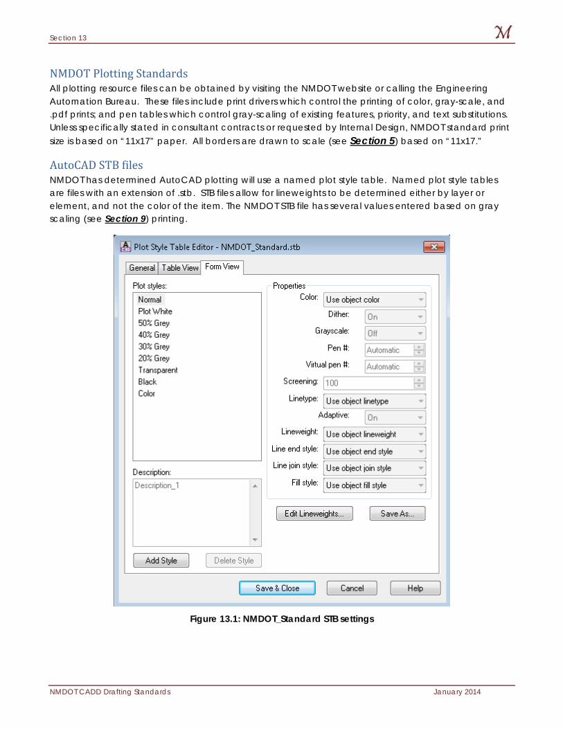
Section 13
NMDOT CADD Drafting Standards January 2014
NMDOT Plotting Standards All plotting resource files can be obtained by visiting the NMDOT website or calling the Engineering Automation Bureau. These files include print drivers which control the printing of color, gray-scale, and .pdf prints; and pen tables which control gray-scaling of existing features, priority, and text substitutions. Unless specifically stated in consultant contracts or requested by Internal Design, NMDOT standard print size is based on “11x17” paper. All borders are drawn to scale (see Section 5) based on “11x17.”
AutoCAD STB files NMDOT has determined AutoCAD plotting will use a named plot style table. Named plot style tables are files with an extension of .stb. STB files allow for lineweights to be determined either by layer or element, and not the color of the item. The NMDOT STB file has several values entered based on gray scaling (see Section 9) printing.
Figure 13.1: NMDOT_Standard STB settings
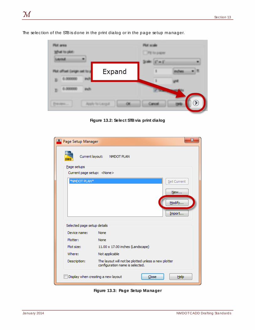
Section 13
January 2014 NMDOT CADD Drafting Standards
The selection of the STB is done in the print dialog or in the page setup manager.
Figure 13.2: Select STB via print dialog
Figure 13.3: Page Setup Manager

Section 15
January 2014 NMDOT CADD Drafting Standards
The page intentionally left blank.
Section 15
NMDOT CADD Drafting Standards January 2014
14: Acceptable Delivery Formats The NMDOT has developed CADD Standards files for internal and consultant use. In order for the NMDOT design departments to complete projects initiated by the consultant community, it is necessary to specify the required deliverable expected by the NMDOT. Given the impact that the design environment brings to both internal and consultant design projects, this specification is critical to the accuracy and digital compatibility between parties. This section will briefly outline the requirements of the NMDOT for all consultants CADD deliverables. Items discussed in this section:
.DWG formats
Packaging
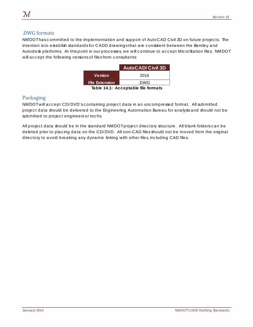
Section 15
January 2014 NMDOT CADD Drafting Standards
.DWG formats NMDOT has committed to the implementation and support of AutoCAD Civil 3D on future projects. The intention is to establish standards for CADD drawings that are consistent between the Bentley and Autodesk platforms. At this point in our processes, we will continue to accept MicroStation files. NMDOT will accept the following versions of files from consultants:
AutoCAD/Civil 3D Version 2016
File Extension .DWG Table 14.1: Acceptable file formats
Packaging NMDOT will accept CD/DVD’s containing project data in an uncompressed format. All submitted project data should be delivered to the Engineering Automation Bureau for analysis and should not be submitted to project engineers or techs.
All project data should be in the standard NMDOT project directory structure. All blank folders can be deleted prior to placing data on the CD/DVD. All non-CAD files should not be moved from the original directory to avoid breaking any dynamic linking with other files, including CAD files.
Section 15
NMDOT CADD Drafting Standards January 2014
15: NMDOT Consultant Workspace The New Mexico Department of Transportation’s (NMDOT) corporate workspace offers NMDOT the opportunity to globally control the CAD environment while retaining necessary levels of personalized, departmental, and project specific settings. This environment gives management the tools to assist NMDOT’s designers and draftsmen by developing an easy to use environment which also controls accurate project settings within the CAD interface. Items discussed in this section.
Consultant Deliverable Workspace
Section 15
January 2014 NMDOT CADD Drafting Standards
Consultant Deliverable Workspace The NMDOT has developed consultant workspaces for AutoCAD and MicroStation to be used by consulting firms producing design projects for the NMDOT. These workspaces are self-contained and “invokes” all necessary NMDOT CADD Standard Files for respective projects. These workspaces are “fully contained,” having the same functionality as the internal NMDOT CADD environment and is similar in operability. The NMDOT workspaces can be downloaded from the NMDOT CADD Standards website. A readme.txt file is included within each download to aid consulting firms in the use of NMDOT workspaces.

Section 16
January 2014 NMDOT CADD Drafting Standards
16: Georeferenced Imaging New Mexico Department of Transportation has utilized raster images for several years. The images published prior to 2009 were a sole-source format of .cot, which was re-named as a .jpg. All images were geo-referenced with the information in a header embedded in the image itself. Raster imaging has undergone tremendous amounts of advances in recent years. Along with these advances, several image formats have become widely accepted in the civil engineering field. The NMDOT standard for raster imagery is the focus of this section. Items discussed in this section:
Imaging Standard
Compression
Section 16
NMDOT CADD Drafting Standards January 2014
Imaging Standard NMDOT has begun to integrate Geographic Information Systems (GIS) technology in the design process. This new direction, has led to many changes to the method in which projects are created and delivered. The workflow for the creation of Geo-referenced images remains consistent with only the delivered file format changing.
NMDOT has set the standard for raster images as a Georeferenced Tiff (GeoTiff) file. The GeoTiff file has become the new standard for raster imaging due to the compatibility with ARC GIS software. All GeoTiffs will be delivered with the accompanying world file, projected in the State Plane Coordinate System and NAD 83.
NMDOT will also accept GeoTiffs including .JPG compression with all GeoReferencing in the header of the image. The basis for .JPG files must be a GeoTiff with a world file to be accepted as a final deliverable for any photogrammetric contracts.
Compression NMDOT has determined a critical need for image compression on all aerial photos submitted to the DOT. The .jpg compression is an industry standard for compressing orthos. NMDOT has adopted the use of .jpg compression. Any other types of compression will be rejected at the consultant’s expense.
Index
January 2014 NMDOT CADD Drafting Standards
Index
.ctb ............................................................................ 11
.dwg .................................................................. 11, 118
.stb ..................................................................... 11, 122 Annotation .................................................... 113, 114 AutoCAD ... 3, 10, 11, 12, 30, 34, 35, 37, 40, 41, 42,
46, 48, 110, 112, 113, 115, 118, 122, 127, 129 Block ................................................ 11, 114, 117, 118 by-level ..................................................................... 48 CAD ........................................................................... 29 CADD .............................. 9, 10, 11, 15, 126, 127, 129 Cell Libraries
Cell ...................................................................... 117 Civil 3D ................................ 3, 10, 17, 20, 35, 40, 127 color .......................................................................... 48 Color Table .............................................................. 11 colors .............................................................. 109, 111 Colors ...................................................................... 111 Consultant Deliverable ........................ 11, 128, 129 coordinate systems .......................................... 39, 41 Extended Characters ............................................ 11 fonts ....................................................... 113, 114, 115 imaging .................................................................. 131 Informational ..................................................... 26, 31 Layers
Levels .............................................................. 11, 48 layouts .......................................................... 30, 39, 42
linestyle......................................................................48 linestyles ................................................... 48, 109, 110 Linestyles ................................................................ 110 linetypes ................................................................. 110 MicroStation ................................... 11, 121, 127, 129 Models ......................................................... 39, 42, 43 Planimetric ...............................................................27 Plotting ................................................................... 122 raster ....................................................................... 131 Raster ................................................................ 11, 131 Reference File ....................................... 11, 30, 45, 46 reference files ..........................................................46 Reference files .........................................................45 seed files ...................................................................39 sheet files ........................................................... 29, 30 software ........................................................... 10, 132 symbology ............................................... 12, 109, 119 symbols .....................................................................13 Symbols .................................................................. 115 template files .................................................... 39, 40 Text .................................................................... 30, 114 Units ............................................... 12, 39, 40, 41, 119 Vector........................................................................12 weight .............................................................. 48, 110 weights ................................................................... 109 Weights .................................................................. 110
Appendix A
NMDOT CADD Drafting Standards January 2014
The page intentionally left blank.