NMB Minebea
50
NMB Minebea Spherical, Rod End and Sleeve Bearings „metric"
Transcript of NMB Minebea

NMB Minebea Spherical, Rod End
and Sleeve Bearings „metric"

4
ENGINEERING DATA
BEARINGCLASSIFICATIONS
Bearings are divided into two basic categories:(1) rolling element or “anti-friction” bearings.(2) sliding surface or “plain” bearings. Except as noted, all bearings in this guide are of the “plain” bearing classification.
TABLE 1 - NMB BEARING CLASSIFICATION BY CONSTRUCTION ELEMENTS
Plain Bearings
Spherical
Rod End
Self Lubricating
Lubricated
Self Lubricating
Lubricated
Self Lubricating
PTFE Lined
Engineering information on rolling element (anti-friction) bearings is presented in other NMB publications except that self-aligning, anti-friction, double row, ball bearing rod end data is included in this guide. (See page 10).
Single Fracture
Double Fracture
Sealed
Standard
Rolling Element Bearings
Swaged
Split Ball
Loader Slot
Sealed
Standard
Non Separable
Separable
Dry Film
PTFE Lined
Minelon TN
Dry Film
PTFE Lined
Minelon TN
Self Aligning Bearings
Journal Bearings
Swaged Type
Insert Type
Fractured Race
Split Ball
Loader Slot
Non Separable
Separable
Plain
Flanged
Single Fracture
Double Fracture
Swaged Type
Fractured Race
Split Ball
Loader Slot
Swaged
Molded
Swaged
Insert
Split Ball
Loader Slot
Die Cast
Swaged
Molded

5
ENGINEERING DATA
CLASSIFICATION INCH SERIES METRIC SERIES
SPHERICAL Metal / Metal ABG ABG-V HABG HABG-V MBG-CR MBG-VCRBEARINGS ABW ABW-V ABY ABY-V MBW-CR MBW-VCR
ABK ABK-V HABK HABK-V MBY-CR MBY-VCRABC-G ABC-VG ABB ABB-S SBH SBWHABC-VA ABC-GA ABC-VGA AM SBW
PTFE lined ABT ABT-V ABWT ABWT-V SBTABYT ABYT-V HT HT-V MBT-V MBTHTY HTY-V WHT WHT-V MBWT-V MBWTHTL HTL-V WHTL WHTL-V MBYT-V MBYT
Minelon TN N/A BM
2 PIECE Metal / Metal AHM AHF N/AROD ENDS PTFE lined AHMT AHFT RBT-E RBT
3 PIECE Metal / Metal AR AR-E ARH ARH-E HR-E HRROD ENDS ARYM ARYF ARB ARB-E HRH-E HRH
AMM AMF
PTFE lined ART ART-E ARHT ARHT-E HRT-E HRTARYT ARYT-E ANM ANF HRHT-E HRHTARNM ARNF
4 PIECE Metal / Metal CAMR CAFR AMR AFR PR-E PRROD ENDS (insert type)
DIE CAST Metal / Metal N/A ERROD ENDS
MOLDED RACE Minelon TN CAMMR CAMFR RBM-E RBMROD ENDS
JOURNAL PTFE lined AJ AJF AHJ AHJF MJ MJFBEARINGS
BALL BEARING (Anti-friction) ABR-M ABR-F ABR-H ABR-S PBR-E PBRROD ENDS
•ROLLER BRGS (Anti-friction) ASR ASRD ASRDG.ASRDF ASRD-V N/A
•ROLLER BRG (Anti-friction) ARR-FFN ARR-MFN ARR-MFN-3 ARR-HFN N/A ROD ENDS ARR-SFN ARRD-HFN ARRD-SFN ARRE-M
ARRDE-M
TABLE 2 - NMB CATALOG BEARING SERIES BY CLASSIFICATION(Bearing Series listed include both aircraft and commercial types)
BEARINGCLASSIFICATIONS
6
ENGINEERING DATA
BEARING TYPES ANDDETAILS OF CONSTRUCTION ENGINEERING DATA
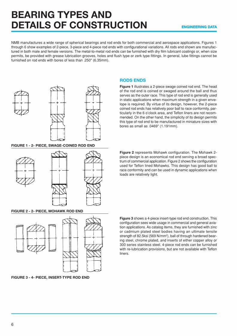
RODS ENDSFigure 1 illustrates a 2-piece swage coined rod end. The headof the rod end is coined or swaged around the ball and thusserves as the outer race. This type of rod end is generally usedin static applications when maximum strength in a given enve-lope is required. By virtue of its design, however, the 2-piececoined rod ends has relatively poor ball to race conformity, par-ticularly in the 6 o’clock area, and Teflon liners are not recom-mended. On the other hand, the simplicity of its design permitsthis type of rod end to be manufactured in miniature sizes withbores as small as .0469" (1.191mm).
Figure 2 represents Mohawk configuration. The Mohawk 2-piece design is an economical rod end serving a broad spec-trum of commercial application. Figure 2 shows the configurationused for Teflon lined Mohawks. This design has good ball torace conformity and can be used in dynamic applications whenloads are relatively light.
Figure 3 shows a 4-piece insert-type rod end construction. Thisconfiguration sees wide usage in commercial and general avia-tion applications. As catalog items, they are furnished with zincor cadmium plated steel bodies having an ultimate tensilestrength of 82.5ksi (569 N/mm2), ball of through hardened bear-ing steel, chrome plated, and inserts of either copper alloy or300 series stainless steel. 4-piece rod ends can be furnishedwith re-lubrication provisions, but are not available with Teflonliners.
NMB manufactures a wide range of spherical bearings and rod ends for both commercial and aerospace applications. Figures 1through 6 show examples of 2-piece, 3-piece and 4-piece rod ends with configurational variations. All rods end shown are manufac-tured in both male and female versions. The metal-to-metal rod ends can be furnished with dry film lubricant coatings or, when sizepermits, be provided with grease lubrication grooves, holes and flush type or zerk type fittings. In general, lube fittings cannot befurnished on rod ends with bores of less than .250" (6.35mm).
FIGURE 2 - 2- PIECE, MOHAWK ROD END
FIGURE 1 - 2- PIECE, SWAGE-COINED ROD END
FIGURE 3 - 4- PIECE, INSERT-TYPE ROD END

7
ENGINEERING DATA
Figure 4 and 5 show 3-piece rod ends with 2 types of insertretention. All bearings shown can be furnished in grease lubri-cated, dry film lubricated or Teflon lined versions. The V-groovestaked design illustrated in Figure 4 is the most widely usedconfiguration in aerospace applications. Three V-groove typescovering inch bearing sizes 3 through 24 have been standard-ized by MS bearing and rod end specifications. The V-groove ismachined into the race face after swaging. The outer lip formedby this groove is flared over the housing chamfer. This methodprovides moderate thrust capacity and allows a worn bearingto be removed and replaced with no damage to the housing.
Figure 5 illustrates a housing stake configuration. This methodis generally used only when there is insufficient space on therace face for a V-groove, or when other factors such as non-ductile race material. Race shear strength or economy of pro-duction are considered.
Figure 6 shows a rod end design using the reverse Messer-schmidt principle. The ball is not fractured but machined andground in matched sets with zero gap at the separation plane.The body is usually of hardened CRES, the ball of copper alloy.Worn balls can be removed manually and replaced. Maximumbody strength and bearing projected area results from the factthat loader slots are omitted.
BEARING TYPES ANDDETAILS OF CONSTRUCTION
FIGURE 4 - 3- PIECE, V-GROOVE STAKED ROD END
FIGURE 5 - 3- PIECE, HOUSING STAKED ROD END
FIGURE 6 - 2- PIECE, SPLIT BALL ROD END

8
ENGINEERING DATA
BEARING TYPES ANDDETAILS OF CONSTRUCTION
SPHERICAL BEARINGSFigure 7 illustrate the procedures used in manufacturing a stan-dard type swaged spherical bearing. The finished ball is in-serted into the cylindrical race blank by slip fit and installed intothe assembly die. After removal from the die, the race O.D. isspherical in shape as shown in the “As Swaged” view. At thisstage, the ball and race are locked firmly, together and inca-pable of relative movement. Following subsequent machining,the bearing assembly is released (loosened) to the torque orradial clearance required and the O.D. is then ground to thefinished size.
Figure 8 demonstrates an alternative swaging method usedwhen the bearing geometry precludes or renders impracticalthe double swaging method shown in figure 7. The pre-formdesign is used when the bearing outer race is not symmetricalabout the spherical centerline due to a flange or a wide over-hang on one side or a combination of both. In such case, theproblem side of the race is pre-formed by machining and grind-ing and the opposite side only is swaged.
Figure 9 shows a loader slot, or “Messerschmidt” bearing de-sign. This is a non-swaged bearing type. The spherical I.D. ismachined and then precision ground after hardening. The loaderslots are profile milled prior to heat treatment. This design per-mits the ball to be inserted and removed manually in the fieldwithout need of tooling. Additional advantages of this designare that extremely close tolerance radial and axial clearancescan be attained, and very high strength materials and surfacecoatings can be used on the outer race. A major disadvantageof the design is the need to properly orient the slots with re-spect to the applied loads due to the loss of bearing projectedarea. In addition, it is difficult to retain grease and exclude con-taminants unless the loader slots are sealed.
FIGURE 7 - SWAGED SPHERICAL BEARING
FIGURE 8 - SWAGED PRE - FORM BEARING
FIGURE 9 - LOADER SLOT BEARING

9
ENGINEERING DATA
BEARING TYPES ANDDETAILS OF CONSTRUCTION
Figure 10 illustrates a double fractured race bearing. This typeof bearing can be furnished in either a single or double frac-tured configuration. The retaining ring groove is provided onlyon the double fractured race design and serves as a recess fora retaining wire or spring which holds the race halves togetherto facilitate handing until the bearing is installed into its hous-ing. Both race and ball are made of bearing steel, through hard-ened and precision ground. All surfaces of the ball and racecoated with zinc phosphate and a dry film of molybdenum dis-ulfide (MoS2). In addition, lube grooves and lube holes are pro-vided to permit relubrication through either the housing or shaft.For corrosive environments, balls and races of through hard-ened stainless steel can be furnished. NMB manufactures cata-log series of single and double fractured race bearings in bothinch and metric sizes. Nitrile rubber (NBR) seals can be pro-vided as option for all sizes.
Figure 11 shows two examples of snap-assembled or “pop-in”bearing configurations. When component geometry permits (arelatively large diameter, thin section, narrow ball and race), abearing may be snap-assembled. Snap-assembly is accom-plished by deflecting the race, ball, or both within their elasticlimits to allow entry of the ball into the race. This type of designis generally used only when all other methods are impracticalor impossible due to problem geometry or processing restraints.
FIGURE 10 - FRACTURED RACE BEARING
FIGURE 11 - SNAP-ASSEMBLED BEARINGS

10
ENGINEERING DATA
BEARING TYPES ANDDETAILS OF CONSTRUCTION
JOURNAL BEARINGS (SELF-LUBRICATING) MS SERIES
Figure 12 shows the NMB AJ and AHJ series which are ap-proved for procurement to MS21240 and MS81934/1 seriesrespectively.
Figure 13 shows the NMB AJF and AHJF series which areapproved for procurement to MS21241 and MS81934/2 seriesrespectively.
ROLLER BEARINGS (SELF - ALIGNING) MS SERIES
Figure 15 shows various MS series of roller bearing rod ends and bearings NMB roller bearings are approved for procurement toAS8952 & AS8914 and MS21221, MS21223, MS21220, MS21429, MS21431, MS28913 and MS28914.
FIGURE 12 - PLAIN, TEFLON LINED FIGURE 13 - FLANGE, TEFLON LINED
Figure 14 shows internal construction of a double row ball bearing rod end. Ball bearing rod ends are typically used for low load, lowfriction, dynamic applications. Configuration permits bearing misalignment to 10° in either direction. Inner rings and balls are madeof 52100 steel with bodies made of 4130 steel or 8620 steel. Bearings are cadmium plated for corrosion protection and prepacked ingrease. NMB ball bearing rod ends are approved for procurement to AS6039 and MS21150, MS21151, MS21152, and MS21153.
ROD END BEARINGS - AIRFAME (ANTI-FRICTION) SERIES
FIGURE 14 - DOUBLE ROW, BALL, ROD END PRECISION SERIES

11
ENGINEERING DATA
SELF-LUBRICATINGLINER SYSTEMS
TEFLON* OR POLYTETRAFLUOROETHYLENE(PTFE) - has good wear and excellent low friction propertiesand makes the ideal bases for a self lubricating liner. However,pure PTFE has a very low strength and must therefore be rein-forced in some way to produce an acceptable load carryingsurface.
NMB Teflon liners have a woven textile backing (such asGlassfiber, Dacron or Nomex) to give required strength , with aPTFE fiber interwoven to provide the self lubricating proper-ties. The PTFE fiber is concentrated towards the front of theliner where the low wear and self lubricating properties arerequired, with the majority of the reinforcing textile fiber at theback to ensure a good bonding surface. The liner is impreg-nated with Phenolic resin for added strength. (See Figure 16).A thermosetting bonding agent applied under temperature andpressure ensures a good bond between the liner and the basemetal.
SOME CHARACTERISTICS OFTHE PTFE LINER1. Modulus of elasticity: 4.5 ✕ 105 psi. (3.1 ✕ 105 N/cm2)2. Coefficient of thermal expansion: 11.6 ✕ 10-6 in/in/°F.
(20.9 ✕ 10-6 mm/mm/°C)3. Low coefficient of friction ranging from approximately .02
to .10. As shown in Figure 17, the coefficient decreases asload and temperatures increase.However the coefficient also increases as surface speedand mating surface roughness increase.
4. Noiseless in operation.5. Is non-corrosive.6. Resistant to most chemicals, greases and oils, however
wear rates may increase when movement takes place un-der contaminated conditions.
7. Is non-conductive and non-magnetic.8. After an initial run-in period, wear rates remain low and rela-
tively constant.9. Can continue to function satisfactorily with wear as high as
.010" (0.25mm).
* A trade name of E.I. duPont de Nemours & Co., Inc
FIGURE 16 - ORIENTATION OF FIBERS AND RESININ PTFE FABRIC LINER
CO
EF
FIC
IEN
T O
F F
RIC
TIO
N (
AP
PR
OX
IMAT
E) .10
.08
.06
.04
.02
FIGURE 17 - EFFECT OF TEMPERATURE AND LOADON COEFFICIENT OF FRICTION
12
ENGINEERING DATA
SELF-LUBRICATINGLINER SYSTEMS
WE
AR
- IN
CH
ES
WE
AR
- IN
CH
ES
0
0 25 50 75 100 125 150
50 100 150 200 250 300
.001
.002
.003
.004
.005
.006
.001
.002
.003
.004
.005
.006
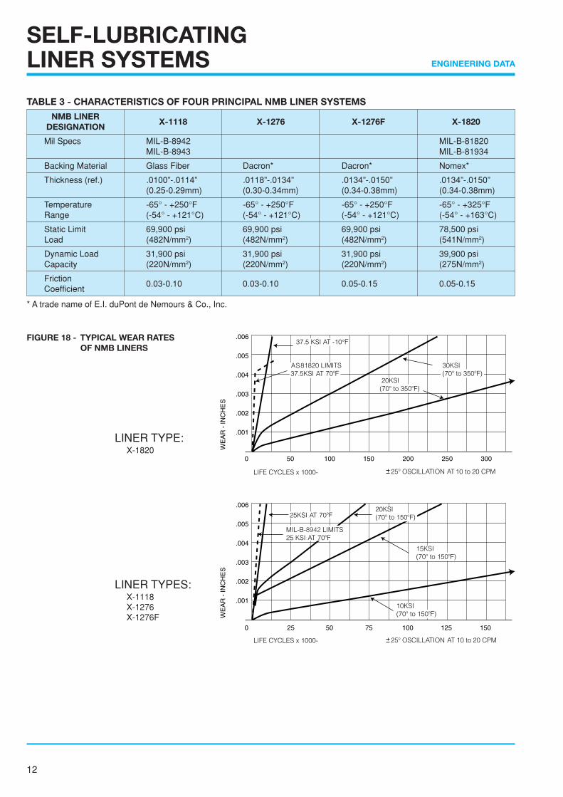
FIGURE 18 - TYPICAL WEAR RATESOF NMB LINERS
LINER TYPE: X-1820
LINER TYPES: X-1118 X-1276 X-1276F
TABLE 3 - CHARACTERISTICS OF FOUR PRINCIPAL NMB LINER SYSTEMS
NMB LINERX-1118 X-1276 X-1276F X-1820
DESIGNATION
Mil Specs MIL-B-8942 MIL-B-81820MIL-B-8943 MIL-B-81934
Backing Material Glass Fiber Dacron* Dacron* Nomex*
Thickness (ref.) .0100”-.0114” .0118”-.0134” .0134”-.0150” .0134”-.0150”(0.25-0.29mm) (0.30-0.34mm) (0.34-0.38mm) (0.34-0.38mm)
Temperature -65° - +250°F -65° - +250°F -65° - +250°F -65° - +325°FRange (-54° - +121°C) (-54° - +121°C) (-54° - +121°C) (-54° - +163°C)
Static Limit 69,900 psi 69,900 psi 69,900 psi 78,500 psiLoad (482N/mm2) (482N/mm2) (482N/mm2) (541N/mm2)
Dynamic Load 31,900 psi 31,900 psi 31,900 psi 39,900 psiCapacity (220N/mm2) (220N/mm2) (220N/mm2) (275N/mm2)
Friction0.03-0.10 0.03-0.10 0.05-0.15 0.05-0.15
Coefficient
* A trade name of E.I. duPont de Nemours & Co., Inc.
13
ENGINEERING DATA
DY
NA
MIC
LO
AD
FA
CT
OR
302520
15
10
54
3
2
1.5
1
0.8
0.60.5
BEARING LIFE-CYCLES
1.5 21 3 4 5 1.5 21 3 4 5 1.5 21 13 4 5
SELF-LUBRICATINGLINER SYSTEMS
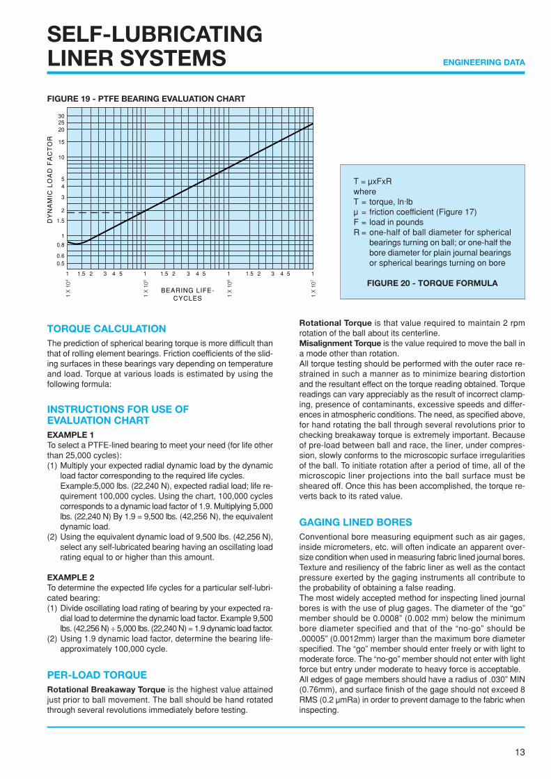
TORQUE CALCULATIONThe prediction of spherical bearing torque is more difficult thanthat of rolling element bearings. Friction coefficients of the slid-ing surfaces in these bearings vary depending on temperatureand load. Torque at various loads is estimated by using thefollowing formula:
INSTRUCTIONS FOR USE OFEVALUATION CHARTEXAMPLE 1To select a PTFE-lined bearing to meet your need (for life otherthan 25,000 cycles):(1) Multiply your expected radial dynamic load by the dynamic
load factor corresponding to the required life cycles.Example:5,000 lbs. (22,240 N), expected radial load; life re-quirement 100,000 cycles. Using the chart, 100,000 cyclescorresponds to a dynamic load factor of 1.9. Multiplying 5,000lbs. (22,240 N) By 1.9 = 9,500 lbs. (42,256 N), the equivalentdynamic load.
(2) Using the equivalent dynamic load of 9,500 lbs. (42,256 N),select any self-lubricated bearing having an oscillating loadrating equal to or higher than this amount.
EXAMPLE 2To determine the expected life cycles for a particular self-lubri-cated bearing:(1) Divide oscillating load rating of bearing by your expected ra-
dial load to determine the dynamic load factor. Example 9,500lbs. (42,256 N) ÷ 5,000 lbs. (22,240 N) = 1.9 dynamic load factor.
(2) Using 1.9 dynamic load factor, determine the bearing life-approximately 100,000 cycle.
PER-LOAD TORQUERotational Breakaway Torque is the highest value attainedjust prior to ball movement. The ball should be hand rotatedthrough several revolutions immediately before testing.
Rotational Torque is that value required to maintain 2 rpmrotation of the ball about its centerline.Misalignment Torque is the value required to move the ball ina mode other than rotation.All torque testing should be performed with the outer race re-strained in such a manner as to minimize bearing distortionand the resultant effect on the torque reading obtained. Torquereadings can vary appreciably as the result of incorrect clamp-ing, presence of contaminants, excessive speeds and differ-ences in atmospheric conditions. The need, as specified above,for hand rotating the ball through several revolutions prior tochecking breakaway torque is extremely important. Becauseof pre-load between ball and race, the liner, under compres-sion, slowly conforms to the microscopic surface irregularitiesof the ball. To initiate rotation after a period of time, all of themicroscopic liner projections into the ball surface must besheared off. Once this has been accomplished, the torque re-verts back to its rated value.
GAGING LINED BORESConventional bore measuring equipment such as air gages,inside micrometers, etc. will often indicate an apparent over-size condition when used in measuring fabric lined journal bores.Texture and resiliency of the fabric liner as well as the contactpressure exerted by the gaging instruments all contribute tothe probability of obtaining a false reading.The most widely accepted method for inspecting lined journalbores is with the use of plug gages. The diameter of the “go”member should be 0.0008” (0.002 mm) below the minimumbore diameter specified and that of the “no-go” should be.00005” (0.0012mm) larger than the maximum bore diameterspecified. The “go” member should enter freely or with light tomoderate force. The “no-go” member should not enter with lightforce but entry under moderate to heavy force is acceptable.All edges of gage members should have a radius of .030” MIN(0.76mm), and surface finish of the gage should not exceed 8RMS (0.2 µmRa) in order to prevent damage to the fabric wheninspecting.
T = µxFxRwhereT = torque, ln·lbµ = friction coefficient (Figure 17)F = load in poundsR = one-half of ball diameter for spherical
bearings turning on ball; or one-half thebore diameter for plain journal bearingsor spherical bearings turning on bore
FIGURE 20 - TORQUE FORMULA
FIGURE 19 - PTFE BEARING EVALUATION CHART
14
ENGINEERING DATA
SELF-LUBRICATINGLINER SYSTEMS
FACTORS AFFECTING THE SELECTION, PERFORMANCE AND EVALUATION OFPTFE-LINED SPHERICAL, ROD END JOURNAL BEARINGS
An answer to situations where the performance envelopecannot be covered by metal to metal bearings is to con-sider PTFE-lined bearings. Here, the lubricant configura-tion is such that it functions as the load carrying elementof the bearing, as represented by the liner systems cur-rently in use. PTFE bearings may be specified under all orsome of the following situations:
1. Where lubrication is undesirable, difficult to perform, or im-poss ib le .
2. Where loads are high and angular movement is low. Underthese circumstances, rolling element bearings fail rapidly.
3. Where space is limited. A PTFE-lined bearing in high load-low speed environments is usually much smaller in sizethan a rolling element bearing.
4. Where vibration is present. A PTFE-lined bearing is morelikely to accept vibration than is a rolling element bearing.
5. Where temperature of the environment renders greasingunfeasible.
6. Where a joint must remain static for extended long periodsof time before movement is initiated.
7. Where friction in a greased bearing would be so high as torender the joint area unless after a limited number of cyclesor impose an unacceptable fatigue situation.
8. Where, in static joints, fretting is a problem.
While PTFE-lined bearings can do an excellent job in manyareas, there have been areas of misapplication. Also, thereexist some misunderstandings regarding life and failureas applied to hardware of this type. We may define someof these concepts as follows:
1. The PTFE-lined bearing starts life with a finite rotationalpre-load torque or clearance.
2. This rotational pre-load torque always decreases with bear-ing usage and clearance always increases with usage.
3. A bearing may be said to have failed if the rotational pre-load torque drops below some specified value. This is al-ways a systems application characteristic.
4. A bearing may be said to have failed when the clearancegenerated by wear exceeds some specified value. This,again, is always some specified systems characteristic.
5. A bearing may be said to have failed if the liner wearsthrough enough to permit the ball to contact the race.
6. No bearing, including PTFE-lined bearings, will last forever.The “Lifetime” lubrication concept applies to the bearingalone, not to the end usage item.
7. The presence of liner debris on a bearing is not a definitiveindication of failure.
8. PTFE-lined bearings tend to telegraph their impending fail-ure by increased radial and axial play.

15
ENGINEERING DATA
SELF-LUBRICATINGLINER SYSTEMS
When evaluating the probable service life of a PTFE-linedbearing application, there are some factors that do notappear in the PV = K relationship. Some considerationsfor a given application might include:
1. Surface sliding speed.
2. Maximum ambient temperature.
3. Size of the heat sink.
4. Acceptable friction levels.
5. Load per unit of area, or liner stress level.
6. Mode of load application; i.e., the duty cycle.
7. Service alignment accuracy, particularly with respect tosleeve and flanged bearings.
8. Surrounding atmosphere.
9. Tolerable wear rate.
10. Surface finish of the bearing mating shaft and the shaftmaterial.
Cost is not included in the above list since it does not af-fect the serviceability of any bearing. Higher individualbearing costs may many times result in a more economi-cal or lower priced finished assembly.
Other aspects of applying PTFE-lined bearings relate tomany obscure factors. The airframe industry is a case inparticular. They readily accept the L10 life concept in evalu-ating rolling element bearings but tend to reject it in linedbearings. In dealing with the troubleshooting relating tolined bearings at the user level, we may summarize mostof them as follows:
1. Customers specify bearings to certain generalized specifica-tions which may or may not reflect end usage requirements.
2. Customers very often have no idea, nor can they definewhat loads or loading situations the bearings may be sub-jected to during the design stage.
3. Continued upgrading of TBO performance on the part ofusers may not be consistent with established structuralenvelopes.
4. A marked difference exists between what is acceptable onmilitary aircraft versus civil aircraft. Apparently specifica-tion writers overlook this aspect entirely.
5. Most customers and users do not realize that life in a linedbearing is limited. They accept this fact on clutches andbrakes, but they apparently cannot see the similarity withrespect to lined bearings.
6. No acceptable criteria have been established with respectto design or acceptable life for this type of bearing. There-fore it is almost impossible for a bearing supplier to initiateall-encompassing test programs.
7. Many bearings are removed and replaced because of de-tectable play between ball and race. Some bearings havebeen removed that still have specification pre-load torque.We must conclude that the potential service life of the bear-ing is not being used.
8. Confusion exists with regard to liner wear. The term “ex-truded liner” often noted on field UR’s is not sufficiently de-finitive. Wear debris is normal to this type of bearing andmust be differentiated from true liner failure.
9. The term “dynamic load rating” or “oscillating load rating”should not be used to select a bearing for an application.These ratings have no relationship to actual applicationsand relate to a qualification condition only.
10. Many line bearings are removed because of fretting be-tween the bearing outer race and the adjacent structure.The use of metal-to-metal bearings will not eliminate thisproblem. This situation can be cured only by proper selec-tion of materials and interface surface finishes.
16
ENGINEERING DATA
GREASE AND DRYLUBRICANTS
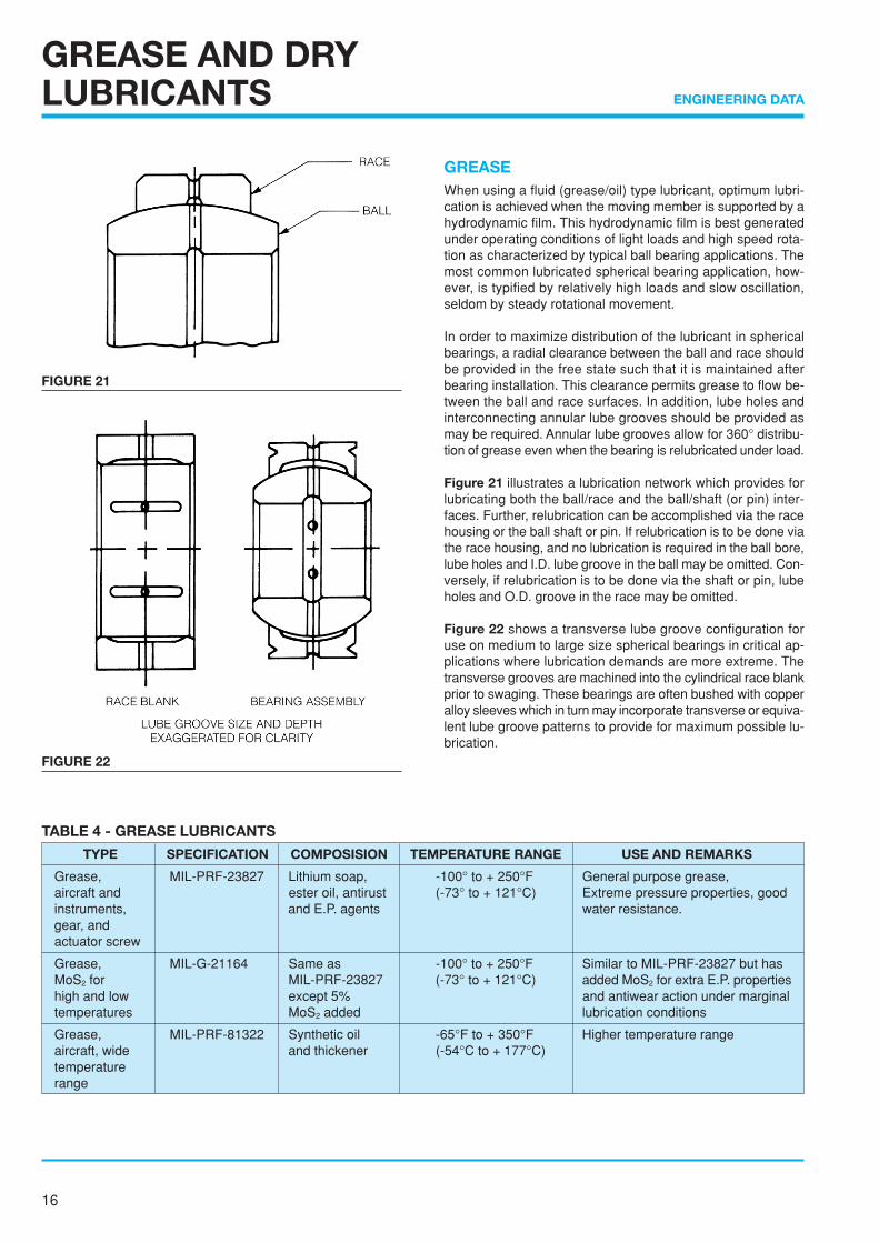
GREASEWhen using a fluid (grease/oil) type lubricant, optimum lubri-cation is achieved when the moving member is supported by ahydrodynamic film. This hydrodynamic film is best generatedunder operating conditions of light loads and high speed rota-tion as characterized by typical ball bearing applications. Themost common lubricated spherical bearing application, how-ever, is typified by relatively high loads and slow oscillation,seldom by steady rotational movement.
In order to maximize distribution of the lubricant in sphericalbearings, a radial clearance between the ball and race shouldbe provided in the free state such that it is maintained afterbearing installation. This clearance permits grease to flow be-tween the ball and race surfaces. In addition, lube holes andinterconnecting annular lube grooves should be provided asmay be required. Annular lube grooves allow for 360° distribu-tion of grease even when the bearing is relubricated under load.
Figure 21 illustrates a lubrication network which provides forlubricating both the ball/race and the ball/shaft (or pin) inter-faces. Further, relubrication can be accomplished via the racehousing or the ball shaft or pin. If relubrication is to be done viathe race housing, and no lubrication is required in the ball bore,lube holes and I.D. lube groove in the ball may be omitted. Con-versely, if relubrication is to be done via the shaft or pin, lubeholes and O.D. groove in the race may be omitted.
Figure 22 shows a transverse lube groove configuration foruse on medium to large size spherical bearings in critical ap-plications where lubrication demands are more extreme. Thetransverse grooves are machined into the cylindrical race blankprior to swaging. These bearings are often bushed with copperalloy sleeves which in turn may incorporate transverse or equiva-lent lube groove patterns to provide for maximum possible lu-brication.
TABLE 4 - GREASE LUBRICANTS
TYPE SPECIFICATION COMPOSISION TEMPERATURE RANGE USE AND REMARKS
Grease, MIL-PRF-23827 Lithium soap, -100° to + 250°F General purpose grease,aircraft and ester oil, antirust (-73° to + 121°C) Extreme pressure properties, goodinstruments, and E.P. agents water resistance.gear, andactuator screw
Grease, MIL-G-21164 Same as -100° to + 250°F Similar to MIL-PRF-23827 but hasMoS2 for MIL-PRF-23827 (-73° to + 121°C) added MoS2 for extra E.P. propertieshigh and low except 5% and antiwear action under marginaltemperatures MoS2 added lubrication conditions
Grease, MIL-PRF-81322 Synthetic oil -65°F to + 350°F Higher temperature rangeaircraft, wide and thickener (-54°C to + 177°C)temperaturerange
FIGURE 21
FIGURE 22

17
ENGINEERING DATA
GREASE AND DRYLUBRICANTS
Table 4 shows three most common grease lubricants used inNMB bearings and rod ends. Rod ends requiring relubricationare generally furnished with zerk type or flush type lube fittingsexcept in those cases where relubrication is to be accomplishedvia the shaft or pin.
Proper, periodic relubrication of grease lubricated sphericalbearings is essential to optimum bearing performance and longservice life. Frequent relubrication reduces wear and friction,prevents fretting and galling, and minimize chemical corrosion.
DRY FILMDry film, also referred to as “solid film”, lubricants are generallyused in applications which preclude the use of grease lubri-cated or PTFE lined bearings. In certain cases, however, theymay be used as a “back-up” for grease lubricated bearings.
The majority of dry film lubricants consist of MoS2 and smallquantities of other materials, such as graphite or powered met-als. Coatings may be applied by spraying, brushing or dippingand are hardened by cure baking at temperatures which mayvary from 200° to 1,000°F (93° to 538°C). Both organic resinsand inorganic binders may be used.
Table 5 lists two common types of dry film lubricants used inaerospace bearings. In addition to these, however, NMB usesa wide variety of dry film compounds selected by our engi-neers to best meet the requirements of specific applications.Dry film selection factors include:■ Temperature Range■ Compatibility with oils and greases■ Static load capacity■ Dynamic wear characteristics■ Exposure to extreme environments, i.e., vacuum LOX,
radiation, etc.
TABLE 5 - DRY FILM LUBRICANTS
TYPE SPECIFICATION LUBRICANT BINDER TEMPERATURE RANGE USE AND REMARKS
Solid film MIL-PRF-46010 MoS2 (no graphite Organic resins -90° to + 400°F Good wear Life andhear cured, or powdered (-68° to + 204°C) provide corrosioncorrosion metals), and protection to substrate.inhibiting corrosion Used for most bearing
inhibitors applications otherthan extreme temperaturesituationsMust have phosphatecoating pretreatment foreffective use on steel
Solid film, MIL-PRF-81329 MoS2 and other Inorganic -300° to + 1200°F To be used in extremeextreme solid lubricants binders (-184° to + 648°C) environments, i.e.,environment vacuum, liquid oxygen,
high temperatures.Wear life not as good asresin-bonded types
18
ENGINEERING DATA
LOCKING DEVICES,KEYS AND KEYWAYS
NAS 1193 KEY
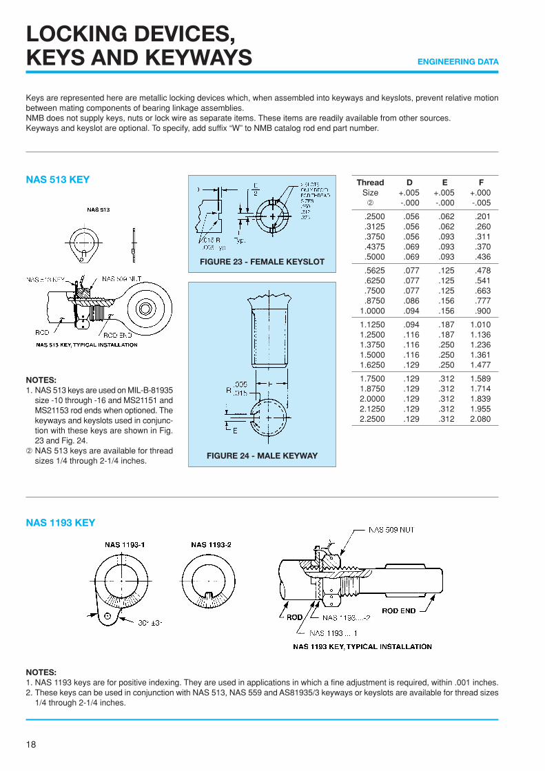
NAS 513 KEY Thread D E FSize +.005 +.005 +.000
➁ -.000 -.000 -.005
.2500 .056 .062 .201
.3125 .056 .062 .260
.3750 .056 .093 .311
.4375 .069 .093 .370
.5000 .069 .093 .436
.5625 .077 .125 .478
.6250 .077 .125 .541
.7500 .077 .125 .663
.8750 .086 .156 .7771.0000 .094 .156 .900
1.1250 .094 .187 1.0101.2500 .116 .187 1.1361.3750 .116 .250 1.2361.5000 .116 .250 1.3611.6250 .129 .250 1.477
1.7500 .129 .312 1.5891.8750 .129 .312 1.7142.0000 .129 .312 1.8392.1250 .129 .312 1.9552.2500 .129 .312 2.080
NOTES:1. NAS 1193 keys are for positive indexing. They are used in applications in which a fine adjustment is required, within .001 inches.2. These keys can be used in conjunction with NAS 513, NAS 559 and AS81935/3 keyways or keyslots are available for thread sizes
1/4 through 2-1/4 inches.
NOTES:1. NAS 513 keys are used on MIL-B-81935
size -10 through -16 and MS21151 andMS21153 rod ends when optioned. Thekeyways and keyslots used in conjunc-tion with these keys are shown in Fig.23 and Fig. 24.
➁ NAS 513 keys are available for threadsizes 1/4 through 2-1/4 inches.
Keys are represented here are metallic locking devices which, when assembled into keyways and keyslots, prevent relative motionbetween mating components of bearing linkage assemblies.NMB does not supply keys, nuts or lock wire as separate items. These items are readily available from other sources.Keyways and keyslot are optional. To specify, add suffix “W” to NMB catalog rod end part number.
FIGURE 23 - FEMALE KEYSLOT
FIGURE 24 - MALE KEYWAY

19
ENGINEERING DATA
LOCKING DEVICES,KEYS AND KEYWAYS
Thread D E F RSize +.005 +.005 +.000 ±.010➀ -.000 -.000 -.005
.2500 .056 .062 .201 .255
.3125 .056 .062 .260 .255
.3750 .056 .093 .311 .255
.4375 .069 .093 .370 .255
.5000 .069 .093 .436 .255
.5625 .077 .125 .478 .255
.6250 .077 .125 .541 .255
.7500 .077 .125 .663 .255
.8750 .086 .156 .777 .3181.0000 .094 .156 .900 .318
1.1250 .094 .187 1.010 .3821.2500 .116 .187 1.136 .3821.3750 .116 .250 1.236 .4451.5000 .116 .250 1.361 .4451.6250 .129 .250 1.477 .445
1.7500 .129 .312 1.589 .5081.8750 .129 .312 1.714 .5082.0000 .129 .312 1.839 .5082.1250 .129 .312 1.955 .5082.2500 .129 .312 1.080 .508
AS81935/3 key NOTES:1. AS81935/3 keys are used on AS81935
sizes -3 through - 8 when optioned. Thekeyways and keyslots used in conjunc-tion with these keys are shown in Fig.27 and Fig. 28.
➁AS81935/3 keys are available forthread sizes 1/4 through 1/2 inches.
Thread Size E F(Male) +.005 +.000
➁ -.000 -.005
.2500-28UNJF-3 .062 .207
.3125-24UNJF-3 .062 .268
.3750-28UNJF-3 .093 .319
.4375-20UNJF-3 .093 .383
.5000-20UNJF-3 .093 .445
NAS 559 TYPE A KEY
NOTES:➀The keyways and keyslots used in con-
junction with these keys are shown inFig. 25 and Fig. 26. The NAS 559 keysare available for thread sizes 1/4through 2-1/4 inches.
➁Keyway flat may vary from standard onsmaller size rod ends but shall extendat least beyond minimum thread lengthin all cases.
FIGURE 27 - FEMALE KEYWAY FIGURE 28 - MALE KEYWAY
FIGURE 25 - FEMALE KEYSLOT
FIGURE 26 - MALE KEYWAY
AS81935/3 KEY,TYPICAL INSTALLATION
.255±.010 +.015
-.000

20
ENGINEERING DATA
BEARING INSTALLATIONAND RETENTION
GENERALA bearing in the free state is not a functioning bearing. Its per-formance begins only after its has been installed into its endassembly, and the methods, fits and forces applied in installa-tion will often determine its success or failure in service.
A surprising percentage of early bearing failures can be traceddirectly to improper mounting conditions. Some examples offrequently occurring installation errors are:(1) excessive interference fit between housing bore and bear-ing O.D. (2) improperly designed staking tools. (3) excessivestaking forces applied.
The following pages are offered not as a comprehensive guideto answer all questions regarding fits, installation, retention,etc., but rather to point out to the bearing user certain areasthat require attention and consideration if the installation is toprovide for optimum bearing performance and life.
HOUSINGSThe housing into which the bearing is to be mounted should bedesigned to ensure the structural integrity and dynamic perfor-mance capability of the bearing. NMB offers the following hous-ing design recommendations:1. Bearing-to-housing fit: (See table 7).2. Bore finish : 32 RMS (0.8 µmRa)3. Roundness within the bore diametrical tolerance.4. Bore perpendicular to housing faces within .002" (0.05 mm).5. Housing width : uniform within .005" (0.13 mm) to ensure
staking integrity.6. Maximum edge breaks of .005" (0.13 mm) when housing is
to be staked over bearing.7. Chamber sizes as calculated per figure 29 formula for V-
groove staking retention.8. Provide for plating or other surface treatments (as may be
required) if housing and bearing are of dissimilar metals.(See table 6).
Another material consideration, in addition to dissimilar met-als, is that of differing coefficients of thermal expansion be-tween the bearing and housing materials. When the bearing isto be operating over a broad temperature range, and the mat-ing bearing and housing have different coefficients of expan-sion, special adjustments may be required in the bearing tohousing fit to prevent either excessive looseness or excessivetorque at temperature extremes.
FIGURE 29 - HOUSING CHAMFER CALCULA-TION FOR V-GROOVE STAKING.
CHAMFER DIAMETER(C) = bearing O.D. + [T-H + (2 ✕ E)]T = housing thicknessH = outer race thicknessE = V groove depth in race

21
ENGINEERING DATA
BEARING INSTALLATIONAND RETENTION
TABLE 6 - TREATMENTS TO PREVENT GALVANIC CORROSION OF DISSIMILAR METALS
Bearing MaterialHousing or Shaft Material
Aluminum Low Alloy Titanium Corrosion Superalloys(Bore and O.D. Surface)Alloys Steel Resistant Steel
Aluminum alloys A A,C A A,C A,C
Bronze and brass A,C C S S S
Bronze and brass,cadmium plated
A C X S S
52100 and low alloy steels A,C C X C C
440C stainless steel A,C C S S S
440C with wet primer A C S S S
Corrosion resistantsteels, 300 series, A,C C S S S17-4PH, 15-5PH, PH13-8Mo, etc
Superalloys A,C C S S S
X = IncompatibleA = Anodize aluminum per MIL-A-8625,Type II, or Alodine per MIL-C-5541C = Cadmium plate per AMS-QQ-P-416, Type I, Class2S = Satisfactory for use with no surface treatment required.
TABLE 7 - HOUSING BORE TOLERANCES FOR METAL TO METAL AND PTFE LINED BEARINGS
BEARING HOUSING BORE
TYPE STYLEO.D. Tolerances Fit-up
inch mm inch mm inch mm
Up to Up to +.0000 +0.000Line to Line Line to Line
1.750 44.45 -.0005 -0.013to to
METAL TOSphericals
.0010 tight 0.025 tightMETAL 1.750 44.45
+.0000 +0.000Line to Line Line to Line
and and-.0008 -0.020
to toover over .0013 tight 0.033 tight
+.0005 +0.013Line to Line Line to Line
Sphericals All All-.0000 -0.000
to to.0010 loose 0.025 loose
PTFE Up to Up to -.0007 -0.018 .0002 to .0012 0.005 to 0.030LINED 1.000 25.40 -.0012 -0.030 tight tight
1.000 25.40-.0010 -0.025 .0005 to .0015 0.013 to 0.038
and and-.0015 -0.038 tight tight
over over
Plain andFlanged Journal(Sleeve) Bearings

22
ENGINEERING DATA
BEARING INSTALLATIONAND RETENTION
SPHERICAL BEARING INSTALLATIONUse of an arbor press or hydraulic press is recommended. Un-der no circumstances should a hammer or any other type of shockincluding impact method be used. A suitable installation tool (asshown in Figure 30) is advised. A guide pin aligns the ball in a90° position, but all force is applied to the outer race only. A leadchamfer or radius on either the bearing or housing is essential.
V-GROOVE RETENTION(V-GROOVE SERIES)For bearings with race staking grooves, a double anvil stakingmethod as shown in Figure 31 is recommended. This methodis best performed on a hydraulic or pneumatic press.
STAKING PROCEDURE:1. Install bearing into housing per Figure 30 and position it sym-
metrical about housing centerline within .005" (0.127 mm).2. Mount bearing and top anvil over bottom anvil guide pin as
shown in Figure 31.3. A trial assembly should be made for each new bearing lot
to determine the staking force necessary to meet the axialretention load required. Excessive force should be avoidedsince this may result in bearing distortion and seriously im-pair bearing function and life. (See Staking Force, Page 21.)
4. Apply the staking force established by trial assembly, ro-tate assembly 90° and re-apply force. Repeat operationthrough a minimum of 3 rotations to ensure 360° uniformityof lip swaging.
5. After staking, a slight gap may exist between race lip andhousing chamfer as shown in detail in Figure 31. This gapshould not be a cause for rejection providing bearing meetsthe thrust load specified.
HOUSING STAKE RETENTION(CHAMFERED BEARING SERIES)Retention of chamfered bearings may be accomplished by manymethods and may vary according to housing configuration, ma-terial, hardness and the axial thrust load requiered When axialloads are light to moderate, a housing ring staking tool as shownin Figure 32 may be used. The bearing and housing are sup-ported by an anvil while the annular staking tool is forced intoone side of the housing flaring a small amount of the housingmaterial over the race chamfer. The opposite side of the hous-ing is then staked in the same manner. When this method isused, the housing crosshole edges should be sharp to a .005"(0.13 mm) maximum radius or chamfer. As with the V-groovestaking, excessive staking forces should be avoided in order toprevent deformation of the spherical bearing.
LINED JOURNAL BEARING INSTALLATIONThe same general procedure as outlined for spherical bearingsshould be followed. (See Figure 30). In the case of fabric Linedbores, however, it is mandatory that both the insertion tool guidepin and the mating shaft have ends free of both burrs and sharpedges. A .030” (0.76 mm) blended radius or 15° lead (as shownin Figure 34) is recommended, since it is virtually impossible toinstall a sharp edged shaft without inflicting some damage to thefabric liner. For maximum support of the fabric lined bore, theeffective length of the insertion tool guide pin should exceed thejournal bearing length.
FIGURE 30
FIGURE 31
FIGURE 32
FIGURE 33 FIGURE 34
➄

23
ENGINEERING DATA
BEARING INSTALLATIONAND RETENTION
TABLE 8 - V-GROOVE STAKING FORCE
GROOVE TYPE* A B C
CONSTANT (lbs) 7,700 12,000 17,700
CONSTANT [N] 34,250 53,376 78,730
*SEE FIGURE 35 FOR GROOVE SIZES
FIGURE 36 - STAKING BEARING PROOF LOAD TESTMETHOD
STAKING FORCEThe force required to stake V-groove bearing is approximatelyequal to the product of the O.D. and a constant for each groovesize. For example, a 1.500” (38.10 mm) O.D. bearing having a“B” size groove should require a staking force of approximately18,000 lbs (80064 N). Constants shown in Table 8 are basedon outer race material having an ultimate tensile strength of140,000 psi (984.6 N/mm2). Staking force constants for othermaterials are proportional to the ultimate tensile of those ma-terials as compared to 140,000 psi (984.6 N/mm2). Stakingforces derived by this formula should be used as a referenceguide only to establish a starting point. Please refer to STAK-ING PROCEDURE steps outlined on page 22.
PROOF LOADINGFigure 36 shows the test set-up specified in AS81935 for axialstatic proof load testing of rod ends with V-groove staked in-serts. This is the generally accepted method used by sphericalbearing and airframe manufactures for checking axial reten-tion of the stake. The rod end assembly is mounted on a rigidring which clears the flared O.D. of the insert and supports therod end body only. The axial proof load is applied to the ballface, the bearing is then reversed 180° and the axial load isrepeated on the opposite side.The approximate proof load can be estimated from TABLE 9.
FIGURE 35 - STANDARD V-GROOVE TYPES & SIZES
TABLE 9 - THRUST LOADS BASED ON FIGURE 35 GROOVE TYPES AND MATERIALS SPECIFIED
X P S Axial Static Proof Load(inch) (mm) (inch) (mm) (inch) (mm) lbs (N)
+.000 +0.00 +.000 +0.000 +.000 +0.00 Steel Race Al-Bz Race-.010 -0.25 -.015 -0.038 -.010 -0.25 (30 ~ 35 HRC)
A .045 1.14 .030 0.76 .020 0.51 1,700 ✕ D” (298 ✕ D mm) 1,100 ✕ D” (193 ✕ D mm)
B .055 1.40 .040 1.02 .030 0.76 2,090 ✕ D” (367 ✕ D mm) 1,360 ✕ D” (239 ✕ D mm)
C .080 2.03 .060 1.52 .030 0.76 2,340 ✕ D” (411 ✕ D mm) 1,520 ✕ D” (267 ✕ D mm)
V-GrooveType
LOAD
LOAD

24
ENGINEERING DATA
DEFINITIONS FOR ROD END AND SPHERICALBEARING TERMINOLOGY
Radial LoadA load applied normally to the bearing bore axis. (See Figure37).
Axial LoadA load applied along the bearing bore axis. (See Figure 37).
Static LoadIs the load to be supported while the bearing is stationary.
Dynamic LoadIs the load to be supported while the bearing is moving.
Static Radial Limit Load *That static load required to produce a specified permanent setin the bearing. It will vary for a given size as a function of con-figuration. It may also be pin limited or, may be limited as afunction of body restraints as in the case of a rod end bearing.Structurally, it is the maximum load which the bearing can seeonce in its application without impairing its performance.
Static Radial Ultimate Load *That load which can be applied to a bearing without fracturingthe ball, race or rod end eye. The ultimate load rating is usually,but not always, 1.5 times (1.25 times for rod end) the limit load.
Static Axial Limit LoadThat load which can be applied to a bearing to produce a speci-fied permanent set in the bearing structure. Structurally, it isthe maximum load which the bearing can see once in its appli-cation without impairing its performance.
Static Axial Ultimate LoadThat load which can be applied to a bearing without separatingthe ball from the race. The ultimate load rating is usually, butnot always, 1.5 times the limit load.
Axial Static Proof LoadThat axial load which can be applied to a mounted sphericalbearing without pushout of the bearing from the rodend body.
Fatigue LoadThat load which can be applied a rod end bearing withstandinga minimum of 50,000 cycles of alternate load. The loading shallbe tension-tension with 100% of fatigue load and 10% of fa-tigue load.
* LOAD CAPACITY FOR NECK BALL TYPE BEARINGSLoad figures given on the Table of Dimension are based on outerrace load capacity.Pin deformation due to fit, hardness and so on may result incrack of ball (inner race).
LOAD RATINGS ANDMISALIGNMENT CAPABILITIES
FIGURE 39
FIGURE 37
FIGURE 38
25
ENGINEERING DATA
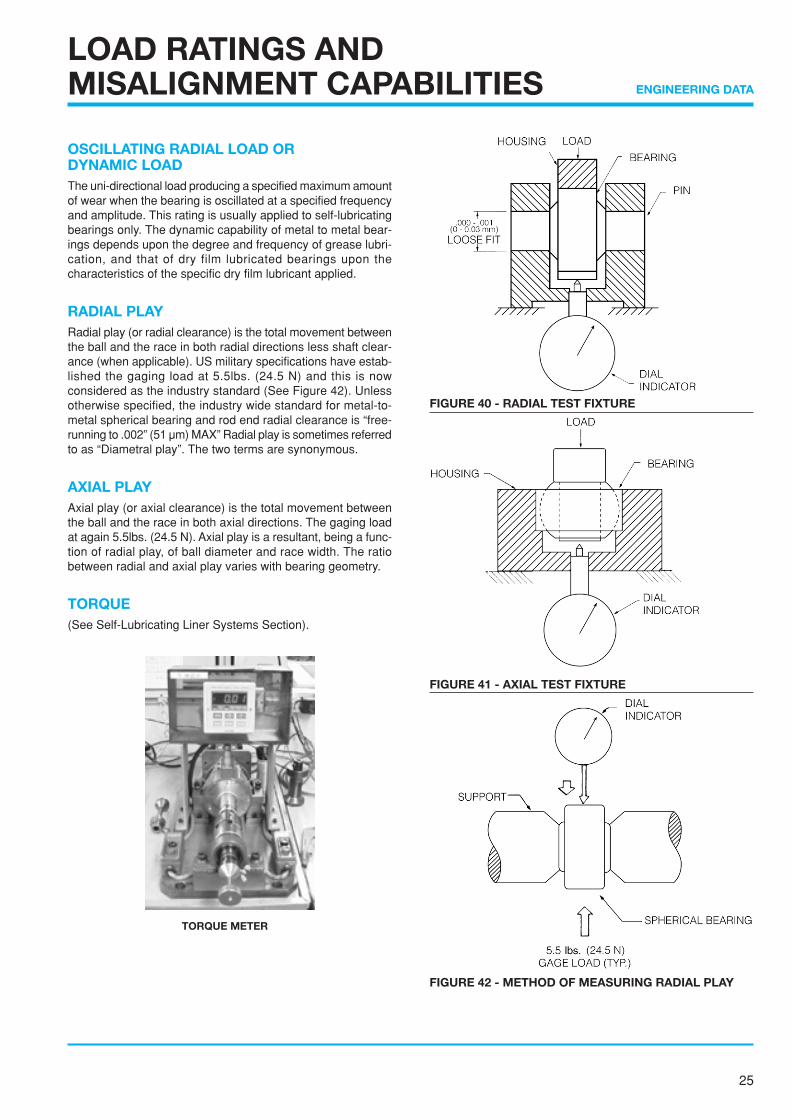
OSCILLATING RADIAL LOAD ORDYNAMIC LOADThe uni-directional load producing a specified maximum amountof wear when the bearing is oscillated at a specified frequencyand amplitude. This rating is usually applied to self-lubricatingbearings only. The dynamic capability of metal to metal bear-ings depends upon the degree and frequency of grease lubri-cation, and that of dry film lubricated bearings upon thecharacteristics of the specific dry film lubricant applied.
RADIAL PLAYRadial play (or radial clearance) is the total movement betweenthe ball and the race in both radial directions less shaft clear-ance (when applicable). US military specifications have estab-lished the gaging load at 5.5lbs. (24.5 N) and this is nowconsidered as the industry standard (See Figure 42). Unlessotherwise specified, the industry wide standard for metal-to-metal spherical bearing and rod end radial clearance is “free-running to .002” (51 µm) MAX” Radial play is sometimes referredto as “Diametral play”. The two terms are synonymous.
AXIAL PLAYAxial play (or axial clearance) is the total movement betweenthe ball and the race in both axial directions. The gaging loadat again 5.5lbs. (24.5 N). Axial play is a resultant, being a func-tion of radial play, of ball diameter and race width. The ratiobetween radial and axial play varies with bearing geometry.
TORQUE(See Self-Lubricating Liner Systems Section).
LOAD RATINGS ANDMISALIGNMENT CAPABILITIES
FIGURE 40 - RADIAL TEST FIXTURE
FIGURE 42 - METHOD OF MEASURING RADIAL PLAY
FIGURE 41 - AXIAL TEST FIXTURE
TORQUE METER

26
ENGINEERING DATA
LOAD RATINGS ANDMISALIGNMENT CAPABILITIES
LOAD RATINGSThe load rating of a bearing is determinedby the dimensions and strength of its weak-est component. External factors, such asmounting components, pins, bolts, andhousings are not considered part of a bear-ing when load ratings are investigated butshould be considered separately.
SPHERICAL BEARING LOADRATINGSThe weakest part, or load-limiting area, ofa spherical bearings is its race. For this rea-son, formulas have been developed thatuse the race to calculate static load ratingsbased on size and material strength. Thestatic load rating formulas for self-lubricat-ing and metal-to-metal spherical bearingsare shown in figure 43 and 44. These for-mulas will yield approximate ratings, whichshould be used as ballpark numbers forbearing design.The allowable radial stress figures givenin the tables were determined from theultimate tensile strength specifications forvarious race materials. Allowable axialstress figures were derived from materialyield strengths.
Load = Projected area x allowable stressRadial Projected Area = (.91T) (DB)Axial Projected Area = .636T2 - .05DB
Allowable StressTeflon-Lined Bearings
FIGURE 43 - Static load rating formulas for self-lubricating spherical bearings.
Allowable StressMetal To Metal Bearings
Load = Projected Area x Allowable stressRadial Projected Area = (.83T - .92G) (DB)Axial Projected Area = .636T2
Standard Groove SizeBearing Size GBore Code Width (mm)3 & 4 .062 (1.57)5-10 .078 (1.98)12-16 .094 (2.39)20 & above .109 (2.77)
FIGURE 44 - Static load rating formulas for metal to metal spherical bearings.
Allowable Stress Teflon X-1820 Lined Bearings (psi)
Race Material Radial AxialUltimate Limit Ultimate Limit
17-4PH, 28 HRC MIN 112,500 75,000 67,500 45,000(775 N/mm2) (517 N/mm2) (465 N/mm2) (310 N/mm2)
ALUM 2024-T351 60,000 40,000 36,000 24,000(413 N/mm2) (276 N/mm2) (248 N/mm2) (164 N/mm2)
Allowable Stress Metal To Metal Bearings (psi)
Race Material Radial AxialUltimate Limit Ultimate Limit
17-4PH, 32-36 HRC 150,000 100,000 125,000 83,000(1034 N/mm2) (689 N/mm2) (861 N/mm2) (572 N/mm2)
4130 32-36 HRC 150,000 100,000 125,000 83,000(1034 N/mm2) (689 N/mm2) (861 N/mm2) (572 N/mm2)
A286 (AMS 5737) 140,000 93,000 95,000 63,000(965 N/mm2) (641 N/mm2) (655 N/mm2) (434 N/mm2)
C62300 AI-Bz 75,000 50,000 45,000 30,000(ASTM B150) (517 N/mm2) (345 N/mm2) (310 N/mm2) (207 N/mm2)

27
ENGINEERING DATA
Rod end bearing load ratings can be generated only after care-fully determining the load restrictions that each element of therod end bearing imposes on the entire unit. It order to generatea frame of reference, consider the rod end bearing as a clockface, with the shank pointing down to the 6 o’clock position.The limiting factors in rating a rod end bearing are as follows:
1. The double shear capability of the bolt passing through theball bore.
2. The bearing capability, a function of race material or self-lubricating liner system.
3. The rod end eye or hoop tension stress in the 3 o’clock-9o’clock position.
4. The shank stress area, as function of male or female rodend configuration.
5. The stress in the transition area between the threadedshank transition diameter and the rod end eye or hoop.
Most rod ends will fail under tension loading in about the 4o’clock-8 o’clock portion of the eye or hoop. The hoop stressarea (HSA) can be found as follows:
HSA = .008762 ✕ D2 ✕ Sin-1 + ✕ D2 - T2 - B ✕ TTD
T2
LOAD RATINGS ANDMISALIGNMENT CAPABILITIES
The shank stress area (SSA) is a function of being either maleor female, as follows:For the male:
SSA = (minor thread diameter)2/4
For the female:SSA = [J2-(major thread diameter)2] /4
Pin shear stress (PSS) for a load “F” is as follows:
d2PSS = 2F
The axial load capability of a rod end is a function of thefollowing:
1. The retention method used to mount the bearing in the rodend eye.
2. The axial load capability of the bearing element.
3. The bending moment, if any, placed on the rod end.
4. The race half width T2 of the bearing element.
This is a function of the axial projected area (APA) of thebearing.
APA = ( )T2
2
FIGURE 45

28
ENGINEERING DATA
FORMULA FOR DETERMINING MISALIGNMENTOF ROD END & SPHERICAL BEARINGS
The misalignment angle of a rod end or spherical bearing re-fers to the angle between the ball centerline and the outermember centerline when the ball is misaligned to the extremeposition allowed by the clevis or shaft design, as applicable.
NOTE:SINCE ANGLE “a” APPLIES EQUALLY ON BOTH SIDES OFTHE CENTERLINE, IT FOLLOWS THAT TOTAL MISALIGN-MENT OF THE BEARING IS DOUBLE THE VALUE OBTAINEDFOR “a”.
LOAD RATINGS ANDMISALIGNMENT CAPABILITIES
Figure 46 through 49 illustrate varying types of bearing mis-alignment and a formula for calculating each.
WHERE;a = Angle of MisalignmentB = Bore of BallD = Head Diameter (Rod End)E = Ball spherical DiameterS = Shoulder Diameter (Neck Ball)T = Housing (Race) WidthW = Width of Ball
HOW NMB SPECIFIES CATALOG BEARINGAND ROD END MISALIGNMENT
STANDARD METHODMOST STANDARD ROD END &SPHERICAL BEARING MIS-ALIGNMENT ANGLES SPECI-FIED IN NMB CATALOGS AREBASED ON THIS METHOD.
DESIGN REFERENCETHIS METHOD MAY BE USEDAS DESIGN REFERENCE FORINSTALLATION PURPOSES,BUT SHOULD NOT BE USED ASA FUNCTIONING MISALIGN-MENT UNDER LOAD.
HIGH MISALIGNMENTSERIES METHOD(NECK BALL ONLY) ROD END CLEVIS
MISALIGNMENT
Figure 51 illustrates how misalignment angles for standard ball spherical bearings androd ends are represented in NMB catalog. The misalignment angle is calculated perFigure 46 formula. Neck ball (high misalignment) bearings and rod ends are represented
in the same manner, but are calculated perFigure 48 formula.NMB prefers not to use rod end clevis mis-alignment for the following reason. Therod end clevis misalignment formula pre-supposes a clevis configuration as shownin Figure 49 in which the clevis slot andball faces are of equal width and in directcontact. In aircraft applications the con-figuration shown in Figure 51 is more typi-cal than that of Figure 51 is more typicalthan that of Figure 49. As pictured in Fig-ure 51, the clevis slot is wider than the ballto permit installation of flanged bushingsand/or spacers. This results in a higher butmore variable misalignment capability andthe angle of misalignment becomes a func-tion of the user’s bushing flange or spacerdiameter instead of the fixed rod end headdiameter.
FIGURE 50 FIGURE 51 -TYPICAL RODEND/CLEVISINSTALLATION
FIGURE 46 FIGURE 47 FIGURE 48
FIGURE 49

29
ENGINEERING DATA
LOAD RATINGS ANDMISALIGNMENT CAPABILITIES
PV FactorWhile not a type of loading, the PV factor is very useful in com-paring and predicting test results on high speed-low load ap-plications such as helicopter conditions.PV is the product of the stress (psi or N/mm2) and the velocity(fpm or m/min) applied to a bearing. Caution must be advisedwhen considering extreme values of psi (N/mm2) and fpm (m/min). The extreme must be considered individually as well astogether.Because the PV factor is derived from the geometry and oper-ating conditions of a bearing, it serves as a common denomi-nator in comparing or predicting test results.The formula for determining the PV value for a spherical bear-ing is as follows:
PV = (x) (cpm) (DB) (psi) (.00073)Where:x = Total angular travel in degrees per cyclecpm = cycles per minuteDB = ball diameterpsi = bearing stress (use N/mm2 for metric)
Dynamic Oscillating Radial LoadThe dynamic oscillating radial load ratings given in this catalogfor HT, WHT, HTL and WHTL series self-lubricating sphericalbearings are based on testing in accordance with AS81820. Forconditions other than those specified by AS81820 for catalogpart number, use the formula given below to predict wear.
W = × .0045CLR
2.13
LA
× (100) × 25,000X
( ) (.114mm)
Where:W = calculated wearC = actual total cyclesLR = rated dynamic load (see product tables)LA = actual dynamic loadx = total angular travel in degrees per cycle
For special self-lubricating bearings that do not appear in thiscatalog, determine the radial projected area and multiply by39,900 psi (275 N/mm2). This determines LR, and the formulacan then be used to predict wear.
LOAD DEFINITIONS(Rod End Bearings, Anti-Friction Bearings)
RADIAL LOAD - A load applied normal to the bearing boreaxis.AXIAL LOAD - A load applied along the bearing bore axis.RADIAL LIMIT LOAD - The static load required to produce aspecified increase in radial play or permanent set in the bear-ing structure.Values are based on the basic relationship: Limit Load (lbs)=KND2,where:
K = Load Rating Constant (typically 3200 for rod endbearings)
N = Number of BallsD = Ball Diameter (inch)
AXIAL LIMIT LOAD - The static load required to produce aspecified increase in axial play or permanent set in the bearingstructure.FRACTURE LOAD, RADIAL OR AXIAL - The load that can beapplied to a bearing without fracturing parts or preventing freeturning by hand.The fracture load rating is usually 1.5 times the limit load.DYNAMIC RADIAL LOAD - Load based on average “L-50”life of 10,000 complete 90° oscillatory cycles. Bearing failure isbased upon inspection for evidence of pitting or surface fa-tigue on the balls or raceways.Load ratings for a greater number of cycles may be determinedby multiplying the basic load rating by a factor obtained fromthe life factor chart. (Figure 52)
FIGURE 52
LIFE FACTOR CHART10.0
1.0
0.11000 1,000,000100,00010,000

Page 34
eMINEBEA.COM
Copyright 2006, Minebea Co., Ltd.
SPHERICAL BEARING 〔SELF-LUBRICATING〕
SBTSPHERICAL SELF-LUBRICATING WIDE
Materials
RACE 410 Stainless Steel / Heat Treated
BALL 440C Stainless Steel / Heat Treated
LINER Teflon / Fabric
Description of Types
Dimensions in mm
MINEBEA
Part
No.
φB
H7
φD
0
- 0.013
W
0
- 0.13
H
± 0.13
α(deg.)
φO
Ref.
SφDB
Ref.
No Load Rotational
Breakaway Torque N・m
Static Limit LoadkN
Dynamic
LoadkN
Approx.
Weightg
Standard Radial Axial
SBT3 3 12 6 4.50 11 6.8 9.042 0.06 ~ 0.57
{0.6 ~ 5.8kgf・cm}
13.72 1.56 6.27 5
SBT4 4 14 7 5.25 12 7.6 10.319 17.65 2.25 8.04 7
SBT5 5 16 8 6.00 11 8.8 11.906
0.12 ~ 0.57
{1.2 ~ 5.8kgf・cm}
24.51 2.94 11.17 10
SBT6 6 18 9 6.75 10 11.1 14.288 36.28 3.72 16.57 14
SBT8 8 22 12 9.0012
12.7 17.462 58.83 6.76 26.87 26
SBT10 10 26 14 10.50 15.2 20.638 81.39 9.21 37.16 42
SBT12 12 30 16 12.00 11 17.6 23.812 114.73 18.63 52.46 62
SBT14 14 34 19 13.50 14 19.2 26.988 147.09 23.53 67.27 89
SBT16 16 38 21 15.0013
22.7 30.956 186.32 29.41 85.12 125
SBT18 18 42 23 16.50 24.1 33.3380.23 ~ 0.90
{2.3 ~ 9.2kgf・cm}
215.74 35.30 98.65 165
SBT20 20 46 25 18.00 12 28.8 38.100 274.58 42.16 125.52 220
SBT22 22 50 28 20.00 13 30.3 41.275 333.42 51.97 152.39 285
SBT25 25 56 31 22.00 14 32.4 44.847 0.33 ~ 1.70
{3.4 ~ 17.3kgf・cm}
404.03 65.21 184.65 380
SBT30 30 66 37 25.00 16 38.2 53.181 545.24 84.33 249.28 605
Notes
1. Teflon liner permanently bonded to race I.D.2. Made to order only.3. No Load Rotational Breakaway Torque. Low Torque All Size: 0.02N・m MAX (Radial Clearance 0.05mm MAX)◯ Please consult MINEBEA for availability of bearings in this series.
Bore size ~ 3 ~ 6 ~ 10 ~ 18 ~ 30
H7 Tolerance
(μm)
+ 10
0
+ 12
0
+ 15
0
+ 18
0
+ 21
0

Page 35Copyright 2006, Minebea Co., Ltd.
eMINEBEA.COM
SPHERICAL BEARING 〔SELF-LUBRICATING〕
MBT,MBT-VSPHERICAL SELF-LUBRICATING NARROW
Materials
RACE 410 Stainless Steel / Heat Treated
BALL 440C Stainless Steel / Heat Treated
LINER Teflon / Fabric
Description of Types
Dimensions in mm
MINEBEA Part No.φB
H7
φD
0
- 0.013
W
0
- 0.13
H
± 0.13
α
(deg.)
φO
Ref.
SφDB
Ref.
No Load
Rotational
Breakaway Torque N・m
Staking GrooveStatic Limit
LoadkN
Dynamic
LoadkN
Approx.
Weightg
StandardS0
- 0.25
X0
- 0.25
R0
- 0.25
P0
- 0.4Radial Axial
MBT3/MBT3V 3 10.0 5.0 3.5 15 5.1 7.144
0.12 ~ 0.57
{1.2 ~ 5.8kgf・cm}
0.5 1.0 0.4 0.7
7.84 0.98 3.43 3
MBT4/MBT4V 4 12.0 6.5 4.5 17 5.8 8.731 12.74 1.56 5.88 4
MBT5/MBT5V 5 14.5 7.0 5.5 10 7.6 10.319 18.63 2.45 8.72 7
MBT6/MBT6V 6 16.5 8.5 6.5 11 9.4 12.700
0.7
1.4
0.5
1.0
30.40 3.43 13.72 11
MBT8/MBT8V 8 19.0 9.5 7.0 12 10.7 14.288 37.26 3.92 16.67 14
MBT10/MBT10V 10 21.0 10.0 8.0 8 13.3 16.669 50.01 5.19 22.55 19
MBT12/MBT12V 12 25.0 13.0 10.0 10 15.0 19.844
2.0 1.5
74.53 8.33 33.34 32
MBT14/MBT14V 14 27.5 14.0 11.08
18.3 23.019 101.98 15.69 45.11 42
MBT15/MBT15V 15 29.0 15.0 12.0 19.524.606
118.66 18.63 52.95 50
MBT16/MBT16V 16 30.0 16.0 12.5 10 18.7 123.56 20.39 54.91 53
MBT18/MBT18V 18 34.0 18.0 14.09
22.2 28.575 161.80 25.49 72.56 78
MBT20/MBT20V 20 36.0 19.0 15.0 23.4 30.162 182.40 29.41 81.39 89
MBT22/MBT22V 22 40.0 22.0 18.0 8 25.0 33.338
0.23 ~ 0.90
{2.3 ~ 9.2kgf・cm}
243.20 42.16 108.85 130
MBT25/MBT25V 25 45.0 25.0 20.09
28.8 38.100 308.90 51.97 138.27 185
MBT28/MBT28V 28 50.0 28.0 22.0 34.0 44.053 393.24 63.74 176.51 255
MBT30/MBT30V 30 56.0 30.0 23.0 10 37.0 47.625 444.24 69.62 199.07 350
Notes
1. Teflon liner permanently bonded to race I.D.2. MBT & MBT-V weights are similar.3. Made to order only.4. No Load Rotational Breakaway Torque. Low Torque All Size: 0.02N ・ m MAX (Radial Clearance 0.05mm MAX)◯ Please consult MINEBEA for availability of bearings in this series.
Bore size ~ 3 ~ 6 ~ 10 ~ 18 ~ 30
H7 Tolerance
(μm)
+ 10
0
+ 12
0
+ 15
0
+ 18
0
+ 21
0

Page 36
eMINEBEA.COM
Copyright 2006, Minebea Co., Ltd.
SPHERICAL BEARING 〔SELF-LUBRICATING〕
MBWT,MBWT-VSPHERICAL SELF-LUBRICATING WIDE
Materials
RACE 410 Stainless Steel / Heat Treated
BALL 440C Stainless Steel / Heat Treated
LINER Teflon / Fabric
Description of Types
Dimensions in mm
MINEBEA Part No.φB
H7
φD
0
- 0.013
W
0
- 0.13
H
± 0.13
α
(deg.)
φO
Ref.
SφDB
Ref.
No Load Rotational
Breakaway TorqueN・m
Staking GrooveStatic Limit
LoadkN
Dynamic
LoadkN
Approx.
Weightg
StandardS0
- 0.25
X0
- 0.25
R0
- 0.25
P0
- 0.4Radial Axial
MBWT5/MBWT5V 516.0
11.08.5 15 7.8 13.494
0.06 ~ 0.57
{0.6 ~ 5.8kgf・cm}0.5 1.0 0.4 0.7
43.14 5.98 18.6314
MBWT6/MBWT6V 6
0.12 ~ 0.57
{1.2 ~ 5.8kgf・cm}
13
MBWT8/MBWT8V 8 17.5 8.0 14 10.9 15.478 46.09 5.29 20.59 14
MBWT10/MBWT10V 10 21.0 12.5 10.5 8 12.2 17.462
0.7
1.4
0.5
1.0
68.64 9.21 30.40 23
MBWT12/MBWT12V 12 26.0 16.0 13.0 10 15.4 22.225 116.69 21.57 51.97 46
MBWT14/MBWT14V 14 28.0 17.014.0
8 18.9 25.400 143.1725.49
63.74 55
MBWT15/MBWT15V 15 29.0 18.0 11 19.0 26.194 148.08 65.70 59
MBWT16/MBWT16V 16 30.0 19.0 15.010
19.2 26.988
2.0 1.5
163.77 29.41 73.54 65
MBWT18/MBWT18V 18 33.0 20.016.0
20.4 28.575 184.3633.34
82.37 80
MBWT20/MBWT20V 20 35.022.0
13 22.9 31.750 204.95 92.18 91
MBWT22/MBWT22V 22 41.0 19.0 6 27.1 34.925
0.23 ~ 0.90
{2.3 ~ 9.2kgf・cm}
268.70 47.07 120.62 150
MBWT25/MBWT25V 25 54.035.0 25.0
15 32.3 47.625 483.4682.37
216.72 400
MBWT28/MBWT28V 28 60.014
36.8 50.800 515.82 231.43 490
MBWT30/MBWT30V 30 64.037.0
26.0 40.4 54.769 578.59 89.24 258.89590
MBWT35/MBWT35V 35 65.0 29.0 9 44.7 58.000
0.33 ~ 1.70
{3.4 ~ 17.3kgf・cm}
682.54 109.83 303.02
MBWT40/MBWT40V 40 68.0 38.0 31.0
8
46.9 60.325 759.03 125.52 337.34 615
MBWT45/MBWT45V 45 76.0 41.0 33.0 54.1 67.866 909.07 142.19 404.03 825
MBWT50/MBWT50V 50 82.0 44.0 35.0 60.3 74.612 1059.11 156.90 470.71 995
Notes
1. Teflon liner permanently bonded to race I.D.2. MBWT & MBWT-V weights are similar.3. Made to order only.4. No Load Rotational Breakaway Torque. Low Torque All Size: 0.02N ・ m MAX (Radial Clearance 0.05mm MAX)◯ Please consult MINEBEA for availability of bearings in this series.
Bore size ~ 3 ~ 6 ~ 10 ~ 18 ~ 30 ~ 50
H7 Tolerance
(μm)
+ 10
0
+ 12
0
+ 15
0
+ 18
0
+ 21
0
+ 25
0

Page 37Copyright 2006, Minebea Co., Ltd.
eMINEBEA.COM
SPHERICAL BEARING 〔SELF-LUBRICATING〕
MBYT,MBYT-VSPHERICAL
SELF-LUBRICATING
HIGH MISALIGNMENT
Materials
RACE 410 Stainless Steel / Heat Treated
BALL 440C Stainless Steel / Heat Treated
LINER Teflon / Fabric
Description of Types
Dimensions in mm
MINEBEA Part No.φB
H7
φD
0
- 0.013
W
0
- 0.13
H
± 0.13
α
(deg.)
φO
Ref.
SφDB
Ref.
No Load Rotational
Breakaway TorqueN・m
Chamfer Staking GrooveStatic Limit
LoadkN
Dynamic
LoadkN
Approx.
Weightg
StandardC
± 0.2
S0
- 0.25
X0
- 0.25
R0
- 0.25
P0
- 0.4Radial Axial
MBYT5/MBYT5V 5 14 12.5 5.0 17 8.0 11.10.06 ~ 0.57
{0.6 ~ 5.8kgf・cm} 0.50.5 1.0 0.4 0.7
18.63 1.96 7.84 8
MBYT6/MBYT6V 6 19 15.06.5
23 10.015.1
0.12 ~ 0.57
{1.2 ~ 5.8kgf・cm}
36.26 3.43 14.7018
MBYT8/MBYT8V 8 18 16.0 20 10.5
0.6
15
MBYT10/MBYT10V 10 23 20.58.5 22
13.5 20.0
0.7
1.4
0.5
1.0
63.705.97
28.42 32
MBYT12/MBYT12V 12 26 22.0 16.0 22.5 72.03 32.34 42
MBYT14/MBYT14V 14 29 23.5 10.0 20 19.0 26.0 98.00 8.33 44.10 60
MBYT15/MBYT15V 15 33 26.0 12.0 19 20.0 28.0 135.24 18.62 60.76 86
MBYT16/MBYT16V 16 35 30.5 14.0 21 21.5 31.8 179.34 25.48 80.36 120
MBYT18/MBYT18V 18 38 33.0 14.5 15 23.5 32.0 0.8
2.0 1.5
187.18 27.44 83.30 135
MBYT20/MBYT20V 20 4035.5 15.5 18
25.0 35.0 0.23 ~ 0.90
{2.3 ~ 9.2kgf・cm}1.0
219.5231.36
98.00 155
MBYT22/MBYT22V 22 44 29.0 38.8 243.04 108.78 200
Notes
1. Teflon liner permanently bonded to race I.D.2. MBYT & MBYT-V weights are similar.3. Made to order only.4. No Load Rotational Breakaway Torque. Low Torque All Size: 0.02N ・ m MAX (Radial Clearance 0.05mm MAX)◯ Please consult MINEBEA for availability of bearings in this series.
Bore size ~ 3 ~ 6 ~ 10 ~ 18 ~ 30
H7 Tolerance
(μm)
+ 10
0
+ 12
0
+ 15
0
+ 18
0
+ 21
0

Page 38
eMINEBEA.COM
Copyright 2006, Minebea Co., Ltd.
SPHERICAL BEARING 〔METAL TO METAL〕
MBG-CR,MBG-VCRSPHERICAL METAL TO METAL STANDARD
Materials
RACE 410 Stainless Steel
BALL 440C Stainless Steel
Description of Types
Dimensions in mm
MINEBEA Part No.φB
H7
φD
0
- 0.013
W
0
- 0.13
H
± 0.13
α
(deg.)
φO
Ref.
SφDB
Ref.
Staking Groove Static Limit Load kNApprox.
Weightg
S0
- 0.25
X0
- 0.25
R0
- 0.25
P0
- 0.4Radial Axial
MBG3CR/MBG3VCR 3 10.0 5.0 3.5 15 5.1 7.144
0.5 1.0 0.4 0.7
6.17 1.76 3
MBG4CR/MBG4VCR 4 12.0 6.5 4.5 17 5.8 8.731 12.16 2.94 4
MBG5CR/MBG5VCR 5 14.5 7.0 5.5 10 7.6 10.319 19.90 4.41 7
MBG6CR/MBG6VCR 6 16.5 8.5 6.5 11 9.4 12.700
0.7
1.4
0.5
1.0
31.08 6.27 11
MBG8CR/MBG8VCR 8 19.0 9.5 7.0 12 10.7 14.288 35.30 7.25 14
MBG10CR/MBG10VCR 10 21.0 10.0 8.0 8 13.3 16.669 49.81 9.51 19
MBG12CR/MBG12VCR 12 25.0 13.0 10.0 10 15.0 19.844
2.0 1.5
79.43 14.80 32
MBG14CR/MBG14VCR 14 27.5 14.0 11.08
18.3 23.019 103.95 28.34 42
MBG15CR/MBG15VCR 15 29.0 15.0 12.0 19.524.606
118.66 33.73 50
MBG16CR/MBG16VCR 16 30.0 16.0 12.5 10 18.7 124.54 36.67 53
MBG18CR/MBG18VCR 18 34.0 18.0 14.09
22.2 28.575 166.71 45.99 78
MBG20CR/MBG20VCR 20 36.0 19.0 15.0 23.4 30.162 192.21 52.75 89
MBG22CR/MBG22VCR 22 40.0 22.0 18.0 8 25.0 33.338 263.79 76.00 130
MBG25CR/MBG25VCR 25 45.0 25.0 20.09
28.8 38.100 340.29 93.84 185
MBG28CR/MBG28VCR 28 50.0 28.0 22.0 34.0 44.053 439.33 112.77 255
MBG30CR/MBG30VCR 30 56.0 30.0 23.0 10 37.0 47.625 500.13 123.56 350
Notes
1. MBG - CR & MBG - VCR weights are similar.2. Made to order only.3. Radial Clearance All Size: 0.051mm MAX◯ Please consult MINEBEA for availability of bearings in this series.
Bore size ~ 3 ~ 6 ~ 10 ~ 18 ~ 30
H7 Tolerance
(μm)
+ 10
0
+ 12
0
+ 15
0
+ 18
0
+ 21
0

Page 39Copyright 2006, Minebea Co., Ltd.
eMINEBEA.COM
SPHERICAL BEARING 〔METAL TO METAL〕
MBW-CR,MBW-VCRSPHERICAL METAL TO METAL WIDE
Materials
RACE 410 Stainless Steel
BALL 440C Stainless Steel
Description of Types
Dimensions in mm
MINEBEA Part No.φB
H7
φD
0
- 0.013
W
0
- 0.13
H
± 0.13
α
(deg.)
φO
Ref.
SφDB
Ref.
Staking Groove Static Limit Load kNApprox.
Weightg
S0
- 0.25
X0
- 0.25
R0
- 0.25
P0
- 0.4Radial Axial
MBW5CR/MBW5VCR 516.0
11.08.5 15 7.8 13.494
0.5 1.0 0.4 0.759.03 10.68
14
MBW6CR/MBW6VCR 6 13
MBW8CR/MBW8VCR 8 17.5 8.0 14 10.9 15.478 63.74 9.51 14
MBW10CR/MBW10VCR 10 21.0 12.5 10.5 8 12.2 17.462
0.7
1.4
0.5
1.0
94.43 16.37 23
MBW12CR/MBW12VCR 12 26.0 16.0 13.0 10 15.4 22.225 148.08 39.61 46
MBW14CR/MBW14VCR 14 28.0 17.014.0
8 18.9 25.400 182.4045.99
55
MBW15CR/MBW15VCR 15 29.0 18.0 11 19.0 26.194 188.28 59
MBW16CR/MBW16VCR 16 30.0 19.0 15.010
19.2 26.988
2.0 1.5
207.90 52.75 65
MBW18CR/MBW18VCR 18 33.0 20.016.0
20.4 28.575 235.3560.11
80
MBW20CR/MBW20VCR 20 35.022.0
13 22.9 31.750 260.85 91
MBW22CR/MBW22VCR 22 41.0 19.0 6 27.1 34.925 341.27 84.72 150
MBW25CR/MBW25VCR 25 54.035.0 25.0
15 32.3 47.625 612.91146.11
400
MBW28CR/MBW28VCR 28 60.014
36.8 50.800 654.10 490
MBW30CR/MBW30VCR 30 64.0 37.0 26.0 40.4 54.769 733.53 157.88 590
Notes
1. MBW - CR & MBW - VCR weights are similar.2. Made to order only.(3) For below 4mm in Bore size, bearings are without lubrication
grooves.4. Radial Clearance All Size: 0.051mm MAX◯ Please consult MINEBEA for availability of bearings in this series.
Bore size ~ 3 ~ 6 ~ 10 ~ 18 ~ 30
H7 Tolerance
(μm)
+ 10
0
+ 12
0
+ 15
0
+ 18
0
+ 21
0

Page 40
eMINEBEA.COM
Copyright 2006, Minebea Co., Ltd.
SPHERICAL BEARING 〔METAL TO METAL〕
MBY-CR,MBY-VCRSPHERICAL METAL TO METAL
HIGH MISALIGNMENT
Materials
RACE 410 Stainless Steel
BALL 440C Stainless Steel
Description of Types
Dimensions in mm
MINEBEA Part No.φB
H7
φD
0
- 0.013
W
0
- 0.13
H
± 0.13
α
(deg.)
φO
Ref.
SφDB
Ref.
ChamferC
± 0.2
Staking Groove Static Limit Load kNApprox.
Weightg
S0
- 0.25
X0
- 0.25
R0
- 0.25
P0
- 0.4Radial Axial
MBY3CR 3 10.0 8.0 3.029
5.0 8.000.3
0.5 1.0 0.4 0.7
11.76 1.27 3
MBY4CR 4 12.0 10.5 4.0 6.0 10.00 20.49 2.35 5
MBY5CR/MBY5VCR 5 14.0 12.5 5.0 17 8.0 11.10
0.5
28.43 3.62 8
MBY6CR/MBY6VCR 6 19.0 15.06.5
23 10.015.10 50.50 6.27
18
MBY8CR/MBY8VCR 8 18.0 16.0 20 10.5 15
MBY10CR/MBY10VCR 10 23.0 20.58.5 22
13.5 20.00
0.6
0.7
1.4
0.5
1.0
87.57 10.68 32
MBY12CR/MBY12VCR 12 26.0 22.0 16.0 22.50 98.06 42 42
MBY14CR/MBY14VCR 14 29.0 23.5 10.0 20 19.0 26.00 133.37 14.80 60
MBY15CR/MBY15VCR 15 33.0 26.0 12.0 19 20.0 28.00 172.59 33.73 86
MBY16CR/MBY16VCR 16 35.0 30.5 14.0 21 21.5 31.80 228.49 45.99 120
MBY18CR/MBY18VCR 18 38.0 33.0 14.5 15 23.5 32.00 0.8
2.0 1.5
238.30 49.32 135
MBY20CR/MBY20VCR 20 40.035.5 15.5 18
25.0 35.001.0
279.4856.38
155
MBY22CR/MBY22VCR 22 44.0 29.0 38.80 308.90 200
Notes
1. MBY - CR & MBY - VCR weights are similar.2. Made to order only.(3) For below 4mm in Bore size, bearings are without lubrication
grooves.4. Radial Clearance All Size: 0.051mm MAX◯ Please consult MINEBEA for availability of bearings in this series.
Bore size ~ 3 ~ 6 ~ 10 ~ 18 ~ 30
H7 Tolerance
(μm)
+ 10
0
+ 12
0
+ 15
0
+ 18
0
+ 21
0

Page 41Copyright 2006, Minebea Co., Ltd.
eMINEBEA.COM
SPHERICAL BEARING 〔MOLD TYPE〕
BMSPHERICAL MOLD TYPE MINELON®
Materials
RACE Bearing Steel / Heat Treated / Black Oxide Treated
BALL Bearing Steel / Heat Treated / Chrome Plated
MOULDED LINER Minelon®
Dimensions in mm
MINEBEA
Part
No.
φB φD
W
0
- 0.12
H
0
- 0.24
φO
Ref.
R1
± 0.2
R2
± 0.2
α
(deg.)
SφDB
Ref.
No Load Rotational
Breakaway TorqueN・m
Radial
Clearancemm
Radial Static
Limit LoadkN
Axial Static
Limit LoadkN
Dynamic
LoadkN
Approx.
Weightg
BM10 10 19 9 6 13.1 0.5
0.8
12 16.0 0
0.03MAX
22.55 8.38 0.50 10
BM12 12 22 10 7 15.30.8
10 18.00.03MAX
{0.35kgf・cmMAX}30.89 11.47 0.72 15
BM15 15 26 12 9 18.7 8 22.00.06MAX
{0.58kgf・cmMAX}0.05MAX
46.77 17.35 1.15 25
BM17 17 30 14 10 21.2
1.0
10 25.0 59.03 21.86 1.36 40
BM20 20 35 16 12 23.7 9 29.0 72.47 26.87 1.58 62
BM25 25 42 20 16 29.3 7 35.50.11MAX
{1.15kgf・cmMAX}103.26 38.24 1.93 102
Table 1
Table 2
Table 3
Notes
① Operating temperature range: - 50 ℃~+ 100 ℃
② Dynamic Load Ratings: Cd
1. Reversing & Alternating LoadDynamic Load Ratings shall be reduced by half from the values given in the table under the use of reversing and alternating load condition.
2. Factor of Operating Temperature and Sliding SpeedDynamic Load Ratings shall be determined by formula below under the use of High-Temperature and Sliding-Speed condition.Cdt・v=ft・fv・Cd Cdt・v: Dynamic Load Ratings under the use of High-Temperature and Sliding speed.ft: Coefficient of Temperaturefv: Coefficient of Sliding speed
Temp. ℃ ~ 40 ~ 60 ~ 80 ~ 100
ft 1.0 0.95 0.8 0.6
Sliding Speed
m/min~ 0.3 ~ 0.4 ~ 0.5 ~ 0.6 ~ 0.7 ~ 0.8 ~ 0.9 ~ 1.1 ~ 1.5 ~ 2.5
fv 1 0.9 0.8 0.7 0.6 0.5 0.4 0.3 0.2 0.1
③ Static Load Ratings: Cs
1. Dynamic Load Ratings shall be reduced to one-thirds of the values given in the table under the use of that High-Load will be applied con-tiniously or periodically and be reduced to one-sixth of the values given under Reversing and Alternating Load and Impact Load conditions.
2. Factor of Operating TemperatureDynamic Load Ratings shall be determined by formula below under the use of High-Temperature conditions.Cs・t=ft・Cs Cs・t: Dynamic Load Ratings under the use of High-Temperature condition.ft: Coefficient of TemperatureCs: Static Load given in the table
Temp. ℃ ~ 30 ~ 40 ~ 60 ~ 80 ~ 90 ~ 100
ft 1.0 0.95 0.85 0.6 0.5 0.3
④ Thrust Load: PtPlease use thrust load in the range, which does not exceed the thrust load (Table 1 application under temperature environment) from catalogue, and “1/3 of Actual radial Load.”
○ Please consult MINEBEA for availability of bearings in this series.
Bm & Dm indicate averages of I.D. & O.D..
Tolerances
Measure
range
Ball permitted tolerances Race permitted tolerancespermitted tolerances
of Ball width
permitted tolerances
of Race width
Bm B Dm D W H
Over Under Upper Lower Upper Lower Upper Lower Upper Lower Upper Lower Upper Lower
─ 10 0 - 0.008 + 0.002 - 0.010 ─ ─ ─ ─ 0 - 0.120 0 - 0.240
10 18 0 - 0.008 + 0.003 - 0.011 ─ ─ ─ ─ 0 - 0.120 0 - 0.240
18 30 0 - 0.010 + 0.003 - 0.013 0 - 0.009 + 0.005 - 0.014 0 - 0.120 0 - 0.240
30 50 0 - 0.012 + 0.003 - 0.015 0 - 0.011 + 0.008 - 0.019 0 - 0.120 0 - 0.240

2 PIECE ROD END BEARING 〔SELF-LUBRICATING〕
EBEA.COM
eMINRBT-E ROD END MALESELF-LUBRICATING
2 PIECE
Materials
BODY 303 Stainless Steel
BALL 440C Stainless Steel
LINER Teflon / Fabric
Description of Types
Dimensions in mm
MINEBEA
Part
No.
φB
H7
φD
± 0.50
W
0
- 0.13
H
± 0.3
F
± 0.5
TH
JIS Class 2
L
± 0.7
α
(deg.)
φO
Ref.
SφDB
Ref.
Radial Static
Limit LoadkN
Static Ultimate
LoadkN
Approx.
Weightg
RBT3E 3 12 6 4.50 27 M3 × 0.5 15 11 6.8 9.04 0.41 1.66 6
RBT4E 4 14 7 5.25 30 M4 × 0.7 1712
7.6 10.32 0.60 2.45 10
RBT5E 5 16 8 6.00 33 M5 × 0.8 20 8.8 11.91 0.98 3.92 12
RBT6E 6 18 9 6.75 36 M6 × 1.0 22 10 11.1 14.29 1.44 5.78 19
RBT8E 8 22 12 9.00 42 M8 × 1.25 25
12
12.7 17.46 2.69 10.78 32
RBT10E 10 26 14 10.50 48 M10 × 1.5 29 15.2 20.64 4.16 16.67 54
RBT12E 12 30 16 12.00 54 M12 × 1.75 33 17.6 23.81 5.88 23.53 85
RBT14E 14 34 19 13.50 60M14 × 2.0
36 14 19.2 26.99 6.61 26.47 126
RBT15E 15 36 20 14.50 63 38 13 21.5 29.37 8.09 32.36 150
RBT16E 16 38 21 15.00 66 M16 × 2.0 40 15 19.4 28.58 8.33 33.34 185
RBT18E 18 42 23 16.50 72 M18 × 1.5 44 15 21.9 31.75 11.52 46.09 258
RBT20E 20 46 25 18.00 78 M20 × 1.5 47 14 24.4 34.93 12.01 48.05 340
RBT22E 22 50 28 20.00 84 M22 × 1.5 5115
25.8 38.10 13.48 53.93 435
RBT25E 25 56 31 22.00 94 M24 × 2.0 57 29.6 42.86 17.40 69.62 730
RBT28E 28 62 35 24.00 103 M27 × 2.0 6217
32.3 47.63 20.83 83.35 1000
RBT30E 30 66 37 25.00 110 M30 × 2.0 66 34.8 50.80 24.76 99.04 1320
Notes
1. Teflon liner permanently bonded to Body I.D.2. Oscillation load shall be kept within the static load range,
as Teflon liner load endurance is greater than body breaking load.3. Made to order only. (from RBT15E to RBT30E) 4. No Load Rotational Breakaway Torque. Standard All Size: 0.02 ~ 0.34N・m Low Torque All Size: 0.02N・m MAX (Radial Clearance 0.05mm MAX)◯ Please consult MINEBEA for availability of bearings in this series.
Bore size ~ 3 ~ 6 ~ 10 ~ 18 ~ 30
H7 Tolerance
(μm)
+ 10
0
+ 12
0
+ 15
0
+ 18
0
+ 21
0
Page 42 Copyright 2006, Minebea Co., Ltd.

2 PIECE ROD END BEARING 〔SELF-LUBRICATING〕
EBEA.COM
eMINRBT ROD END FEMALESELF-LUBRICATING
2 PIECE
Materials
BODY 303 Stainless Steel
BALL 440C Stainless Steel
LINER Teflon / Fabric
Description of Types
Dimensions in mm
MINEBEA
Part
No.
φB
H7
φD
± 0.5
W
0
- 0.13
H
± 0.3
F
± 0.5
TH
JIS Class 2
L
± 0.7
φN
± 0.5
φP
± 0.5
C
± 0.7
S
± 0.25
α
(deg.)
φO
Ref.
SφDB
Ref.
Radial Static
Limit LoadkN
Static
Ultimate
LoadkN
Approx.
Weightg
RBT3 3 12 6 4.50 21 M3 × 0.5 10.0 6.5 8.0 3.0 7 11 6.8 9.04 0.41 1.66 10
RBT4 4 14 7 5.25 24 M4 × 0.7 12.0 8.0 9.54.0
812
7.6 10.32 0.60 2.45 12
RBT5 5 16 8 6.00 27 M5 × 0.8 12.5 9.0 11.0 9 8.8 11.91 0.98 7.84 16
RBT6 6 18 9 6.75 30 M6 × 1.0 13.5 10.0 13.05.0
11 10 11.1 14.29 1.44 8.62 25
RBT8 8 22 12 9.00 36 M8 × 1.25 16.0 12.5 16.0 14
12
12.7 17.46 2.69 11.76 43
RBT10 10 26 14 10.50 43 M10 × 1.5 19.5 15.0 19.06.5
17 15.2 20.64 4.16 16.67 72
RBT12 12 30 16 12.00 50 M12 × 1.75 24.0 17.5 22.0 19 17.6 23.81 5.88 23.53 107
RBT14 14 34 19 13.50 57M14 × 2.0
27.0 20.0 25.0
8.0 22
14 19.2 26.99 6.61 26.47 160
RBT15 15 36 20 14.50 61 30.0 21.0 26.0 13 21.5 29.37 8.09 32.36 185
RBT16 16 38 21 15.00 64 M16 × 2.0 33.0 22.0 27.0 15 19.4 28.58 8.33 33.34 210
RBT18 18 42 23 16.50 71 M18 × 1.5 36.0 25.0 31.010.0
27 15 21.9 31.75 11.52 46.09 295
RBT20 20 46 25 18.00 77 M20 × 1.5 40.0 27.5 34.0 30 14 24.4 34.93 12.01 48.05 380
RBT22 22 50 28 20.00 84 M22 × 1.5 43.0 30.0 37.0
12.0
3215
25.8 38.10 13.48 53.93 490
RBT25 25 56 31 22.00 94 M24 × 2.0 48.0 33.5 42.0 36 29.6 42.86 17.40 69.62 870
RBT28 28 62 35 24.00 103 M27 × 2.0 53.0 37.5 46.041 17
32.3 47.63 20.83 83.35 1180
RBT30 30 66 37 25.00 110 M30 × 2.0 56.0 40.0 50.0 15.0 34.8 50.80 24.76 99.04 1450
Notes
1. Teflon liner permanently bonded to race I.D.2. Oscillation load shall be kept within the static load range, as Teflon liner load endurance is greater than body breaking load.3. Made to order only. (from RBT15 to RBT30)4. No Load Rotational Breakaway Torque. Standard All Size: 0.02 ~ 0.34N・m Low Torque All Size: 0.02N・m MAX (Radial Clearance 0.05mm MAX)◯ Please consult MINEBEA for availability of bearings in this series.
Bore size ~ 3 ~ 6 ~ 10 ~ 18 ~ 30
H7 Tolerance
(μm)
+ 10
0
+ 12
0
+ 15
0
+ 18
0
+ 21
0
Page 43Copyright 2006, Minebea Co., Ltd.

3 PIECE ROD END BEARINGS 〔SELF-LUBRICATING〕
EBEA.COM
eMINHRT-E MALE ROD ENDSSELF-LUBRICATING
3 PIECE
Materials
HRT-E HRT-ECR
BODY Chromium-Molybdenum Steel Zinc Plated
SUS630 Stainless Steel Passivated
RACE 410 Stainless Steel / Heat Treated 410 Stainless Steel / Heat Treated
BALL 440C Stainless Steel / Heat Treated 440C Stainless Steel / Heat Treated
LINER Teflon / Fabric Teflon / Fabric
Description of Types
Dimensions in mm
MINEBEA
Part
No.
φB
H7
φD
± 0.50
W
0
- 0.13
H
± 0.13
F
± 0.5
TH
JIS Class 2
L
± 0.7
α
(deg.)
φO
Ref.
SφDB
Ref.
No Load Rotational
Breakaway Torque N・m
Static Limit Load
kN(3)
Radial
Static
Ultimate
Load
(3) kN
Fatigue
Load
(3)kN
Approx.
Weightg
Standard Radial Axial (2)
HRT3E 3 16.0 7.0 5.25 30.0 M3 × 0.5 10.0 18 5.2 8.73
0.06 ~ 0.68
{0.6 ~ 6.9kgf・cm}
3.62 1.96 4.51 0.73 25
HRT4E 4 18.0 9.5 7.75 35.0 M4 × 0.7 16.0 16 5.8 11.11 6.27 3.53 7.84 1.27 30
HRT5E 520.5
11.08.75 39.5
M5 × 0.822.0 15 7.8 13.49
10.295.09
12.84 2.1035
HRT6E 6 M6 × 1.0 14.51 18.14 2.99
HRT8E 8 23.0 8.25 46.0 M8 × 1.2529.0
14 10.9 15.48
0.12 ~ 1.13
{1.2 ~ 11.5kgf・cm}
26.77 5.29 33.44 5.54 40
HRT10E 10 26.0 12.5 10.75 47.0 M10 × 1.5 8 12.2 17.46 37.65 6.76 47.07 7.84 65
HRT12E 12 34.0 16.0 13.25 62.0 M12 × 1.75 37.0 10 15.4 22.22 62.46 8.33 78.06 12.94 126
HRT14E 14 36.0 17.014.25
64.0M14 × 2.0 38.0
8 18.9 25.40 82.96 9.02 103.65 17.25 140
HRT15E 15 38.0 18.0 65.0 11 19 26.19100.71 9.70 125.81 20.98
165
HRT16E 16 39.0 19.015.25
66.5 M16 × 2.0 39.5 10 19.2 26.99 195
HRT17E 17 41.020.0
72.5 M16 × 1.5 42.0 1220.4 28.58
101.40 10.29 126.70 21.08 220
HRT18E 18 43.016.30
79.5 M18 × 1.5 46.0 10 120.62 12.16 150.72 25.10 250
HRT20E 20 45.022.0
83.0 M20 × 1.5 50.0 13 22.9 31.75 121.30 12.84 151.61 25.20 290
HRT22E 22 52.0 19.30 86.0 M22 × 1.5 51.0 6 27.1 34.92
0.23 ~ 1.80
{2.3 ~ 18.4kgf・cm}
156.21 15.10 195.25 32.55 450
HRT25E 25 70.035.0 25.30
105.0 M24 × 2.0 59.0 15 32.3 47.62 300.08 20.88 375.10 62.56 1150
HRT28E 28 75.0 110.0 M27 × 2.0 62.014
36.8 50.80 283.70 23.24 354.60 59.13 1500
HRT30E 30 78.0 37.0 26.30 120.0 M30 × 2.0 65.0 40.4 54.77 271.93 24.81 339.89 56.68 1800
Notes
1. Teflon liner permanently bonded to race I.D.
(2) Axial load indicates either the smaller value of static load or proof load.
(3) Special specification can bare higher fatigue load.
4. Made to order only.
5. No Load Rotational Breakaway Torque.Low Torque All Size: 0.02N・m MAX
(Radial Clearance 0.05mm MAX)
◯ Please consult MINEBEA for availability of bearings in this series.
Bore size ~ 3 ~ 6 ~ 10 ~ 18 ~ 30
H7 Tolerance
(μm)
+ 10
0
+ 12
0
+ 15
0
+ 18
0
+ 21
0
Page 44 Copyright 2006, Minebea Co., Ltd.

3 PIECE ROD END BEARINGS 〔SELF-LUBRICATING〕
EBEA.COM
eMINHRT ROD END FEMALESELF-LUBRICATING
3 PIECE
Materials
HRT HRT-CR
BODY Chromium-Molybdenum Steel Zinc Plated
SUS630 Stainless Steel Passivated
RACE 410 Stainless Steel / Heat Treated 410 Stainless Steel / Heat Treated
BALL 440C Stainless Steel / Heat Treated 440C Stainless Steel / Heat Treated
LINER Teflon / Fabric Teflon / Fabric
Description of Types
Dimensions in mm
MINEBEA
Part
No.
φB
H7
φD
± 0.5
W
0
-0.13
H
±0.13
F
± 0.5
TH
JIS Class 2
L
± 0.7
φN
±0.5
φP
±0.5
C
+ 0.2
- 0.7
S
± 0.25
α
(deg.)
φO
Ref.
SφDB
Ref.
No Load
Rotational
Breakaway
Torque N・m
Static Limit
Load
kN(3)
Radial
Static
Ultimate
Load
(3)kN
Fatigue
Load
(3)kN
Approx.
Weightg
Standard RadialAxial
(2)
HRT3 3 16.0 7.0 5.25 30.0 M3 × 0.516
7.0 93.5
8 18 5.2 8.73
0.06 ~ 0.68
{0.6 ~ 6.9kgf・cm}
14.70 1.96 30.89 5.14 29
HRT4 4 18.0 9.5 7.75 32.0 M4 × 0.7 8.5 11 10 16 5.8 11.11 31.38 3.53 43.34 7.15 35
HRT5 5 20.5
11.08.75
35.0 M5 × 0.819 10.8 15 4.5 12 15 7.8 13.49 27.94 5.09 34.91 5.78 40
HRT6 6 20.5 37.0 M6 × 1.0
HRT8 8 23.0 8.25 41.0 M8 × 1.25 22 12.5 17
6.5
14 14 10.9 15.48
0.12 ~ 1.13
{1.2 ~ 11.5kgf・
cm}
34.02 5.29 42.46 7.06 51
HRT10 10 26.0 12.5 10.75 46.0 M10 × 1.5 24 14.0 19 15 8 12.2 17.46 37.65 6.76 47.07 7.84 73
HRT1212 34.0 16.0 13.25 57.0
M12 ×
1.7532 18.5
24 2010 15.4 22.22 78.06 8.33 97.57 16.18 150
HRT14 14 36.0 17.014.25
60.0M14 × 2.0
33 19.0 7.5 8 18.9 25.40 82.96 9.02 103.65 17.25 165
HRT15 15 38.0 18.0 62.0 34 20.0 25 8.5 21 11 19.0 26.19 95.32 9.31 119.15 19.80 189
HRT16 16 39.0 19.015.25
63.5 M16 × 2.0 35 22.0 279.5
23 10 19.2 26.99 100.71 9.70 125.81 20.98 218
HRT17 17 41.020.0
68.0 M16 × 1.5 37 23.0 28 24 1220.4 28.58
101.40 10.29 126.70 21.08 241
HRT18 18 43.016.30
74.0 M18 × 1.5 40 24.030 10.0
26 10 120.62 12.16 150.72 25.10 283
HRT20 20 45.022.0
76.0 M20 × 1.5 41 25.0 26 13 22.9 31.75 121.30 12.84 151.61 25.20 330
HRT22 22 52.0 19.30 85.0 M22 × 1.5 47 28.0 36 12.0 30 6 27.1 34.920.23 ~ 1.80
{2.3 ~ 18.4kgf・
cm}
156.21 15.10 195.25 32.55 580
HRT25 25 70.035.0 25.30
105.0 M24 × 2.0 54 42.0 50 14.0 43 15 32.3 47.62 302.43 20.88 378.04 63.05 1230
HRT28 28 75.0 110.0 M27 × 2.0 58 44.0 56 15.0 4714
36.8 50.80 283.70 23.24 354.60 59.13 1620
HRT30 30 78.0 37.0 26.30 120.0 M30 × 2.0 62 48.0 60 16.0 51 40.4 54.77 271.93 24.81 339.89 56.68 1930
Notes
1. Teflon liner permanently bonded to race I.D.
(2) Axial load indicates either the smaller value of static load or proof load.
(3) Select Type "CR" for higher load capability.
4. Made to order only.
5. No Load Rotational Breakaway Torque.Low Torque All Size: 0.02N・m MAX
(Radial Clearance 0.05mm MAX)
◯ Please consult MINEBEA for availability of bearings in this series.
Bore size ~ 3 ~ 6 ~ 10 ~ 18 ~ 30
H7 Tolerance
(μm)
+ 10
0
+ 12
0
+ 15
0
+ 18
0
+ 21
0
Page 45Copyright 2006, Minebea Co., Ltd.

3 PIECE ROD END BEARINGS 〔METAL TO METAL〕
EBEA.COM
eMINHR-E MALE ROD ENDS METAL TO METAL 3 PIECEMaterials
HR-E HR-ECR
BODY Chromium-Molybdenum Steel Zinc Plated
SUS630 Stainless Steel Passivated
RACE 410 Stainless Steel / Heat Treated 410 Stainless Steel / Heat Treated
BALL Bearing Steel / Chrome Plated Bearing Steel / Heat Treated
Description of Types
Dimensions in mm
MINEBEA
Part
No.
φB
H7
φD
± 0.5
W
0
- 0.13
H
± 0.13
F
± 0.5
TH
JIS Class 2
L
± 0.7
α
(deg.)
φO
Ref.
SφDB
Ref.
Static Limit Load kN Radial
Static
Ultimate
LoadkN
Fatigue
Load
(2)kN
Approx.
Weightg
Radial Axial (1)
HR3E 3 16.0 7.0 5.25 30.0 M3 × 0.5 10.0 18 5.2 8.73 3.62 2.94 4.51 0.73 25
HR4E 4 18.0 9.5 7.75 35.0 M4 × 0.7 16.0 16 5.8 11.11 6.27 3.53 7.84 1.27 30
HR5E 520.5
11.08.75 39.5
M5 × 0.822.0 15 7.8 13.49
10.295.09
12.84 2.1035
HR6E 6 M6 × 1.0 14.51 18.14 2.99
HR8E 8 23.0 8.25 46.0 M8 × 1.2529.0
14 10.9 15.48 26.77 5.58 33.44 5.54 40
HR10E 10 26.0 12.5 10.75 47.0 M10 × 1.5 8 12.2 17.46 37.65 6.76 47.07 7.84 65
HR12E 12 34.0 16.0 13.25 62.0 M12 × 1.75 37.0 10 15.4 22.22 62.46 8.33 78.06 12.94 126
HR14E 14 36.0 17.014.25
64.0M14 × 2.0 38.0
8 18.9 25.40 82.96 9.02 103.65 17.25 140
HR15E 15 38.0 18.0 65.0 11 19.0 26.19 85.90 9.31 107.38 17.84 165
HR16E 16 39.0 19.015.25
66.5 M16 × 2.0 39.5 10 19.2 26.99 100.71 9.70 125.81 20.98 195
HR17E 17 41.020.0
72.5 M16 × 1.5 42.0 1220.4 28.58
101.40 10.29 126.70 21.08 220
HR18E 18 43.016.30
79.5 M18 × 1.5 46.0 10 120.62 12.16 150.72 25.10 250
HR20E 20 45.022.0
83.0 M20 × 1.5 50.0 13 22.9 31.75 121.30 12.84 151.61 25.20 290
HR22E 22 52.0 19.30 86.0 M22 × 1.5 51.0 6 27.1 34.92 156.21 15.10 195.25 32.55 450
HR25E 25 70.035.0 25.30
105.0 M24 × 2.0 59.0 15 32.3 47.62 300.08 20.88 375.10 62.56 1150
HR28E 28 75.0 110.0 M27 × 2.0 62.014
36.8 50.80 283.70 23.24 354.60 59.13 1500
HR30E 30 78.0 37.0 26.30 120.0 M30 × 2.0 65.0 40.4 54.77 271.93 24.81 339.89 56.68 1800
Notes
(1) Axial load indicates either the smaller value of static load or proof load.
(2) Special specification can bare higher fatigue load.
3. Made to order only.
4. Radial clearance All Size: 0.051mm MAX
◯ Please consult MINEBEA for availability of bearings in this series.
Bore size ~ 3 ~ 6 ~ 10 ~ 18 ~ 30
H7 Tolerance
(μm)
+ 10
0
+ 12
0
+ 15
0
+ 18
0
+ 21
0
Page 46 Copyright 2006, Minebea Co., Ltd.

3 PIECE ROD END BEARING 〔METAL TO METAL〕
EBEA.COM
eMINHR ROD END FEMALEMETAL TO METAL
3 PIECE
Materials
HR HR-CR
BODY Chromium-Molybdenum Steel Zinc Plated
SUS630 Stainless Steel Passivated
RACE Stainless Steel / Heat Treated Stainless Steel / Heat Treated
BALL Bearing Steel / Chrome Plated Stainless Steel / Heat Treated
Description of Types
Dimensions in mm
MINEBEA
Part
No.
φB
H7
φD
± 0.5
W
0
- 0.13
H
± 0.13
F
± 0.5
TH
JIS Class 2
L
± 0.7
φN
± 0.5
φP
± 0.5
C
+ 0.2
- 0.1
S
± 0.25
α
(deg.)
φO
Ref.
SφDB
Ref.
Static Limit LoadkN
Radial
Static
Ultimate
LoadkN
Fatigue
Load (2)kN
Approx.
WeightgRadial
Axial
(1)
HR3 3 16.0 7.0 5.25 30.0 M3 × 0.516
7.0 93.5
8 18 5.2 8.73 22.45 2.94 30.89 5.14 29
HR4 4 18.0 9.5 7.75 32.0 M4 × 0.7 8.5 11 10 16 5.8 11.11 34.71 3.53 43.34 7.15 35
HR5 520.5
11.08.75
35.0 M5 × 0.819 10.8 15 4.5 12 15 7.8 13.49 27.94 5.09 34.91 5.78 40
HR6 6 37.0 M6 × 1.0
HR8 8 23.0 8.25 41.0 M8 × 1.25 22 12.5 17
6.5
14 14 10.9 15.48 34.02 5.58 43.44 7.06 51
HR10 10 26.0 12.5 10.75 46.0 M10 × 1.5 24 14.0 19 15 8 12.2 17.46 37.65 6.76 47.07 7.84 73
HR12 12 34.0 16.0 13.25 57.0 M12 × 1.75 32 18.524 20
10 15.4 22.22 78.06 8.33 97.57 16.18 150
HR14 14 36.0 17.014.25
60.0M14 × 2.0
33 19.0 7.5 8 18.9 25.40 82.96 9.02 103.65 17.25 165
HR15 15 38.0 18.0 62.0 34 20.0 25 8.5 21 11 19.0 26.19 95.32 9.31 119.15 19.80 189
HR16 16 39.0 19.015.25
63.5 M16 × 2.0 35 22.0 27 9.5 23 10 19.2 26.99 100.71 9.70 125.81 20.98 218
HR17 17 41.020.0
68.0 M16 × 1.5 37 23.0 28 9.5 24 1220.4 28.58
101.40 10.29 126.70 21.08 241
HR18 18 43.016.30
74.0 M18 × 1.5 40 24.030 10.0 26
10 120.62 12.16 150.72 25.10 283
HR20 20 45.022.0
76.0 M20 × 1.5 41 25.0 13 22.9 31.75 121.30 12.84 151.61 25.20 330
HR22 22 52.0 19.30 85.0 M22 × 1.5 47 28.0 36 12.0 30 6 27.1 34.92 156.21 15.10 195.25 32.55 580
HR25 25 70.035.0 25.30
105.0 M24 × 2.0 54 42.0 50 14.0 43 15 32.3 47.62 300.08 20.88 378.04 63.05 1230
HR28 28 75.0 110.0 M27 × 2.0 58 44.0 56 15.0 4714
36.8 50.80 283.70 23.24 354.60 59.13 1620
HR30 30 78.0 37.0 26.30 120.0 M30 × 2.0 62 48.0 60 16.0 51 40.4 54.77 271.93 24.81 339.89 56.68 1930
Notes
(1) Axial load indicates either the smaller value of static load or proof load.
(2) Special specification can bare higher fatigue load.
3. Made to order only.
4. Radial Clearance All Size: 0.051mm MAX
◯ Please consult MINEBEA for availability of bearings in this series.
Bore size ~ 3 ~ 6 ~ 10 ~ 18 ~ 30
H7 Tolerance
(μm)
+ 10
0
+ 12
0
+ 15
0
+ 18
0
+ 21
0
Page 47Copyright 2006, Minebea Co., Ltd.

4 PIECE ROD END BEARING 〔METAL TO METAL〕
EBEA.COM
eMINPR-E ROD END MALEMETAL TO METAL
4 PIECE
Materials
BODY Low Carbon Steel / Zinc Plated
INSERT Copper Alloy
BALL Bearing Steel / Chrome Plated
Description of Types
Dimensions in mm
MINEBEA
Part
No.
φB
H7
φD
± 0.5
W
0
- 0.13
H
± 0.13
F
± 0.5
TH
JIS Class 2
L
± 0.7
α
(deg.)
φO
Ref.
SφDB
Ref.
Radial
Static Limit LoadkN
Static
Ultimate
LoadkN
Approx.
Weightg
PR3E(1) 3 12 6 4.50 27 M3 × 0.5 15 14 5.2 7.94 1.56 2.45 7
PR4E(1) 4 14 7 5.25 30 M4 × 0.7 17
13
6.5 9.52 2.25 3.53 10
PR5E 5 16 8 6.00 33 M5 × 0.8 20 7.7 11.11 4.51 7.06 13
PR6E 6 18 9 6.75 36 M6 × 1.0 22 9.0 12.70 6.37 9.90 19
PR8E 8 22 12 9.00 42 M8 × 1.25 25 14 10.4 15.88 13.72 21.47 32
PR10E 10 26 14 10.50 48 M10 × 1.5 2913
12.9 19.05 18.82 29.41 54
PR12E 12 30 16 12.00 54 M12 × 1.75 33 15.4 22.22 25.20 39.42 85
PR14E 14 34 19 13.50 60 M14 × 2.0 36 16 16.9 25.40 30.49 47.75 126
PR16E 16 38 21 15.00 66 M16 × 2.0 4015
19.4 28.58 38.04 59.64 185
PR18E 18 42 23 16.50 72 M18 × 1.5 44 21.9 31.75 46.28 72.47 258
PR20E 20 46 25 18.00 78 M20 × 1.5 47 14 24.4 34.92 53.83 84.33 340
PR22E 22 50 28 20.00 84 M22 × 1.5 51 15 25.8 38.10 63.93 100.22 435
Notes
(1) Lubrication fitting are not available for PR3E, PR4E.
2. Radial ClearanceStandard Clearance: 0.051mm MAXLow Clearance: 0.030mm MAX
◯ Please consult MINEBEA for availability of bearings in this series.
Bore size ~ 3 ~ 6 ~ 10 ~ 18 ~ 30
H7 Tolerance
(μm)
+ 10
0
+ 12
0
+ 15
0
+ 18
0
+ 21
0
Page 48 Copyright 2006, Minebea Co., Ltd.
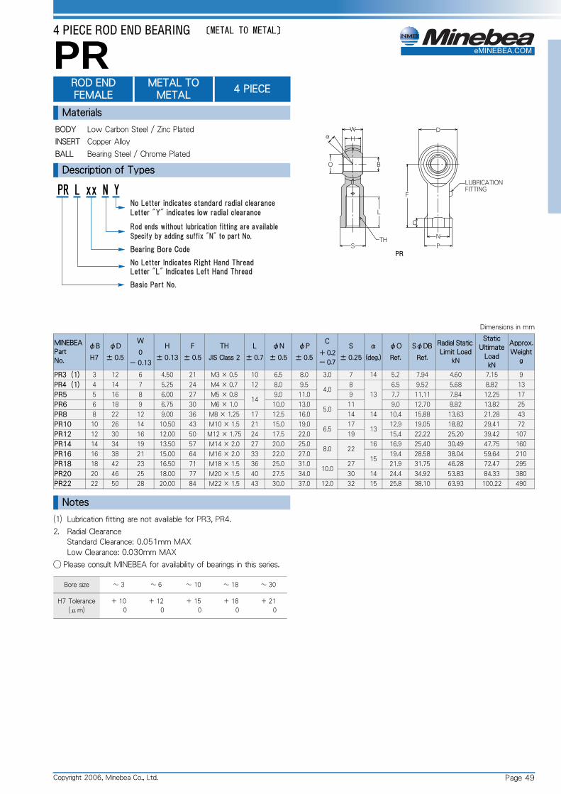
4 PIECE ROD END BEARING 〔METAL TO METAL〕
EBEA.COM
eMINPR ROD END FEMALEMETAL TO METAL
4 PIECE
Materials
BODY Low Carbon Steel / Zinc Plated
INSERT Copper Alloy
BALL Bearing Steel / Chrome Plated
Description of Types
Dimensions in mm
MINEBEA
Part
No.
φB
H7
φD
± 0.5
W
0
- 0.13
H
± 0.13
F
± 0.5
TH
JIS Class 2
L
± 0.7
φN
± 0.5
φP
± 0.5
C
+ 0.2
- 0.7
S
± 0.25
α
(deg.)
φO
Ref.
SφDB
Ref.
Radial Static
Limit LoadkN
Static
Ultimate
LoadkN
Approx.
Weightg
PR3(1) 3 12 6 4.50 21 M3 × 0.5 10 6.5 8.0 3.0 7 14 5.2 7.94 4.60 7.15 9
PR4(1) 4 14 7 5.25 24 M4 × 0.7 12 8.0 9.54.0
8
13
6.5 9.52 5.68 8.82 13
PR5 5 16 8 6.00 27 M5 × 0.814
9.0 11.0 9 7.7 11.11 7.84 12.25 17
PR6 6 18 9 6.75 30 M6 × 1.0 10.0 13.05.0
11 9.0 12.70 8.82 13.82 25
PR8 8 22 12 9.00 36 M8 × 1.25 17 12.5 16.0 14 14 10.4 15.88 13.63 21.28 43
PR10 10 26 14 10.50 43 M10 × 1.5 21 15.0 19.06.5
1713
12.9 19.05 18.82 29.41 72
PR12 12 30 16 12.00 50 M12 × 1.75 24 17.5 22.0 19 15.4 22.22 25.20 39.42 107
PR14 14 34 19 13.50 57 M14 × 2.0 27 20.0 25.08.0 22
16 16.9 25.40 30.49 47.75 160
PR16 16 38 21 15.00 64 M16 × 2.0 33 22.0 27.015
19.4 28.58 38.04 59.64 210
PR18 18 42 23 16.50 71 M18 × 1.5 36 25.0 31.010.0
27 21.9 31.75 46.28 72.47 295
PR20 20 46 25 18.00 77 M20 × 1.5 40 27.5 34.0 30 14 24.4 34.92 53.83 84.33 380
PR22 22 50 28 20.00 84 M22 × 1.5 43 30.0 37.0 12.0 32 15 25.8 38.10 63.93 100.22 490
Notes
(1) Lubrication fitting are not available for PR3, PR4.
2. Radial ClearanceStandard Clearance: 0.051mm MAXLow Clearance: 0.030mm MAX
◯ Please consult MINEBEA for availability of bearings in this series.
Bore size ~ 3 ~ 6 ~ 10 ~ 18 ~ 30
H7 Tolerance
(μm)
+ 10
0
+ 12
0
+ 15
0
+ 18
0
+ 21
0
Page 49Copyright 2006, Minebea Co., Ltd.

MOLDED ROD END BEARING 〔SELF-LUBRICATING〕
EBEA.COM
eMINRBM-E ROD END BEARING MOLDED MINELON TNMaterials
BODY Low Carbon Steel / Zinc Plated
BALL Bearing Steel / Heat Treated / Chrome Plated
LINER Minelon TN
Description of Types
Dimensions in mm
MINEBEA
Part
No.
φB
H7
φD
± 0.5
W
0
- 0.13
H
± 0.13
F
± 0.5
TH
JIS Class 2
L
± 0.7
α
(deg.)
φO
Ref.
SφDB
Ref.
No Load
Rotational
Breakaway
TorqueN・m
Radial
Clearancemm
Radial Static
Limit LoadkN
Dynamic
LoadkN
Approx.
Weightg
RBM5E 5 16 8 6.00 33 M5 × 0.8 20 13 7.7 11.11 0.04MAX
{0.4kgf・cmMAX}0.03MAX
3.62 1.90 12
RBM6E 6 18 9 6.75 36 M6 × 1.0 22 13 9.0 12.70 5.05 2.17 20
RBM8E 8 22 12 9.00 42 M8 × 1.25 2514
10.4 15.88 0.06MAX
{0.6kgf・cmMAX}
0.05MAX
9.16 3.48 35
RBM10E 10 26 14 10.50 48 M10 × 1.5 29 12.9 19.05 14.61 5.14 55
RBM12E 12 30 16 12.00 54 M12 × 1.75 33 13 15.4 22.220.12MAX
{1.2kgf・cmMAX}18.14 6.52 90
RBM14E 14 34 19 13.50 60 M14 × 2.0 36 16 16.9 25.400.34MAX
{3.5kgf・cmMAX}
24.02 8.72 130
RBM16E 16 38 21 15.00 66 M16 × 2.0 40
15
19.4 28.58 28.43 10.49 185
RBM18E 18 42 23 16.50 72 M18 × 1.5 44 21.9 31.75 35.79 13.23 250
RBM20E 20 46 25 18.00 78 M20 × 1.5 47 24.4 34.92 0.57MAX
{5.8kgf・cmMAX}
41.18 15.39 310
RBM22E 22 50 28 20.00 84 M22 × 1.5 51 25.9 38.10 50.01 18.73 400
Table 1
Table 2
Table 3
Notes
① Operating temperature range: - 50 ℃~+ 100 ℃
② Dynamic Load Ratings: Cd
1. Reversing & Alternating LoadDynamic Load Ratings shall be reduced by half from the values given in the table under the use of reversing and alternating load condition.
2. Factor of Operating Temperature and Sliding SpeedDynamic Load Ratings shall be determined by formula below under the use of High-Temperature and Sliding-Speed condition.Cdt・v=ft・fv・Cd Cdt・v: Dynamic Load Ratings under the use of High-Temperature and Sliding speed.ft: Coefficient of Temperaturefv: Coefficient of Sliding speed
Temp. ℃ ~ 40 ~ 60 ~ 80 ~ 100
ft 1.0 0.95 0.8 0.6
Sliding Speed
m/min~ 0.3 ~ 0.4 ~ 0.5 ~ 0.6 ~ 0.7 ~ 0.8 ~ 0.9 ~ 1.1 ~ 1.5 ~ 2.5
fv 1 0.9 0.8 0.7 0.6 0.5 0.4 0.3 0.2 0.1
③ Static Load Ratings: Cs
1. Dynamic Load Ratings shall be reduced to one-thirds of the val-ues given in the table under the use of that High-Load will be applied continiously or periodically and be reduced to one-sixth of the values given under Reversing and Alternating Load and Impact Load conditions.
2. Factor of Operating TemperatureDynamic Load Ratings shall be determined by formula below under the use of High-Temperature conditions.Cs・t=ft・Cs Cs・t: Dynamic Load Ratings under the use of High-Temperature condition.ft: Coefficient of TemperatureCs: Static Load given in the table
Temp. ℃ ~ 30 ~ 40 ~ 60 ~ 80 ~ 90 ~ 100
ft 1.0 0.95 0.85 0.6 0.5 0.3
○ Please consult MINEBEA for availability of bearings in this series.
Bore size ~ 3 ~ 6 ~ 10 ~ 18 ~ 30
H7 Tolerance
(μm)
+ 10
0
+ 12
0
+ 15
0
+ 18
0
+ 21
0
Page 50 Copyright 2006, Minebea Co., Ltd.

MOLDED ROD END BEARING 〔SELF-LUBRICATING〕
EBEA.COM
eMINRBM ROD END BEARINGFEMALEMOLDED MINELON TN
Materials
BODY Low Carbon Steel / Zinc Plated
BALL Bearing Steel / Heat Treated / Chrome Plated
LINER Minelon
Description of Types
Dimensions in mm
MINEBEA
Part
No.
φB
H7
φD
± 0.5
W
0
- 0.13
H
± 0.13
F
± 0.5
TH
JIS Class 2
L
± 0.7
φN
± 0.5
φP
± 0.5
C
+ 0.2
- 0.7
S
± 0.25
α
(deg.)
φO
Ref.
SφDB
Ref.
No Load
Rotational
Breakaway
TorqueN・m
Radial
Clearancemm
Radial
Static
Limit
LoadkN
Dynamic
LoadkN
Approx.
Weightg
RBM5 5 16 8 6.00 27 M5 × 0.814
9.0 11 4.0 913
7.7 11.11 0.04MAX
{0.4kgf・cmMAX}0.03MAX
5.98 1.90 16
RBM6 6 18 9 6.75 30 M6 × 1.0 10.0 135.0
11 9.0 12.70 7.55 2.17 25
RBM8 8 22 12 9.00 36 M8 × 1.25 17 12.5 16 1414
10.4 15.88 0.06MAX
{0.6kgf・cmMAX}
0.05MAX
10.29 3.48 45
RBM10 10 26 14 10.50 43 M10 × 1.5 21 15.0 19
6.5
17 12.9 19.05 14.61 5.14 75
RBM12 12 30 16 12.00 50 M12 × 1.75 24 17.5 22 19 13 15.4 22.220.12MAX
{1.2kgf・cmMAX}18.14 6.52 120
RBM14 14 34 19 13.50 57 M14 × 2.0 27 20.0 258.0 22
16 16.9 25.400.34MAX
{3.5kgf・cmMAX}
24.02 8.72 160
RBM16 16 38 21 15.00 64 M16 × 2.0 33 22.0 27
15
19.4 28.58 28.43 10.49 220
RBM18 18 42 23 16.50 71 M18 × 1.5 36 25.0 3110.0
27 21.9 31.75 35.79 13.23 300
RBM20 20 46 25 18.00 77 M20 × 1.5 40 27.5 34 30 24.4 34.92 0.57MAX
{5.8kgf・cmMAX}
41.18 15.39 380
RBM22 22 50 28 20.00 84 M22 × 1.5 43 30.0 37 12.0 32 25.9 38.10 50.01 18.73 480
Table 1
Table 2
Table 3
Notes
① Operating temperature range: - 50 ~+ 100 ℃
② Dynamic Load Ratings: Cd
1. Reversing & Alternating LoadDynamic Load Ratings shall be reduced by half from the values given in the table under the use of reversing and alternating load condition.
2. Factor of Operating Temperature and Sliding SpeedDynamic Load Ratings shall be determined by formula below under the use of High-Temperature and Sliding-Speed condition.Cdt・v=ft・fv・Cd Cdt・v: Dynamic Load Ratings under the use of High-Temperature and Sliding speed.ft: Coefficient of Temperaturefv: Coefficient of Sliding speed
Temp. ℃ ~ 40 ~ 60 ~ 80 ~ 100
ft 1.0 0.95 0.8 0.6
Sliding Speed
m/min~ 0.3 ~ 0.4 ~ 0.5 ~ 0.6 ~ 0.7 ~ 0.8 ~ 0.9 ~ 1.1 ~ 1.5 ~ 2.5
fv 1 0.9 0.8 0.7 0.6 0.5 0.4 0.3 0.2 0.1
③ Static Load Ratings: Cs
1. Dynamic Load Ratings shall be reduced to one-thirds of the val-ues given in the table under the use of that High-Load will be applied continiously or periodically and be reduced to one-sixth of the values given under Reversing and Alternating Load and Impact Load conditions.
2. Factor of Operating TemperatureDynamic Load Ratings shall be determined by formula below under the use of High-Temperature conditions.Cs・t=ft・Cs Cs・t: Dynamic Load Ratings under the use of High-Temperature condition.ft: Coefficient of TemperatureCs: Static Load given in the table
Temp. ℃ ~ 30 ~ 40 ~ 60 ~ 80 ~ 90 ~ 100
ft 1.0 0.95 0.85 0.6 0.5 0.3
○ Please consult MINEBEA for availability of bearings in this series.
Bore size ~ 3 ~ 6 ~ 10 ~ 18 ~ 30
H7 Tolerance
(μm)
+ 10
0
+ 12
0
+ 15
0
+ 18
0
+ 21
0
Page 51Copyright 2006, Minebea Co., Ltd.
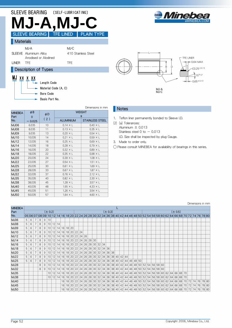
Page 52
eMINEBEA.COM
Copyright 2006, Minebea Co., Ltd.
SLEEVE BEARING 〔SELF-LUBRICATING〕
MJ-A,MJ-CSLEEVE BEARING TFE LINED PLAIN TYPE
Materials
MJ-A MJ-C
SLEEVE Aluminium AlloyAnodised or Alodined
410 Stainless Steel
LINER TFE TFE
Description of Types
Dimensions in mm
MINEBEA
Part
No.
φB
0
- 0.025
φD
( 2 )
WEIGHTg
ALUMINIUM STAINLESS STEEL
MJ06 6.035 10 0.14 × L 0.40 × L
MJ08 8.035 11 0.13 × L 0.35 × L
MJ09 9.035 13 0.20 × L 0.54 × L
MJ10 10.035 14 0.21 × L 0.59 × L
MJ12 12.035 16 0.25 × L 0.69 × L
MJ14 14.035 18 0.28 × L 0.79 × L
MJ16 16.035 20 0.32 × L 0.89 × L
MJ18 18.035 22 0.35 × L 0.98 × L
MJ20 20.035 24 0.39 × L 1.08 × L
MJ22 22.035 27 0.54 × L 1.51 × L
MJ25 25.035 30 0.61 × L 1.69 × L
MJ28 28.035 33 0.67 × L 1.87 × L
MJ32 32.035 37 0.76 × L 2.12 × L
MJ35 35.035 40 0.82 × L 2.30 × L
MJ38 38.035 45 1.28 × L 3.57 × L
MJ40 40.035 48 1.55 × L 4.33 × L
MJ45 45.035 51 1.26 × L 3.54 × L
MJ50 50.035 57 1.64 × L 4.60 × L
Notes
1. Teflon liner permanently bonded to Sleeve I.D.
(2) (a) Tolerances:Aluminium ± 0.013Stainless steel 0 to - 0.013
I.D. Size shall be inspected by plug Gauge.
3. Made to order only.
◯ Please consult MINEBEA for availability of bearings in this series.
Dimensions in mm
MINEBEA
Part
No.
L
〔± 0.2〕 〔± 0.3〕 〔± 0.5〕
05 06 07 08 09 10 12 14 16 18 20 22 24 26 28 30 32 34 36 38 40 42 44 46 48 50 52 54 56 58 60 62 64 66 68 70 72 74 76 78 80
MJ06 5 6 7 8 9 10
MJ08 5 6 7 8 9 10 12 14
MJ09 5 6 7 8 9 10 12 14 16 18 20
MJ10 5 6 7 8 9 10 12 14 16 18 20 22 24
MJ12 5 6 7 8 9 10 12 14 16 18 20 22 24 26
MJ14 5 6 7 8 9 10 12 14 16 18 20 22 24 26 28 30
MJ16 5 6 7 8 9 10 12 14 16 18 20 22 24 26 28 30 32 34
MJ18 5 6 7 8 9 10 12 14 16 18 20 22 24 26 28 30 32 34 36
MJ20 5 6 7 8 9 10 12 14 16 18 20 22 24 26 28 30 32 34 36 38
MJ22 5 6 7 8 9 10 12 14 16 18 20 22 24 26 28 30 32 34 36 38 40 42 44
MJ25 5 6 7 8 9 10 12 14 16 18 20 22 24 26 28 30 32 34 36 38 40 42 44 46 48 50
MJ28 8 9 10 12 14 16 18 20 22 24 26 28 30 32 34 36 38 40 42 44 46 48 50 52 54 56 58 60
MJ32 8 9 10 12 14 16 18 20 22 24 26 28 30 32 34 36 38 40 42 44 46 48 50 52 54 56 58 60
MJ35 10 12 14 16 18 20 22 24 26 28 30 32 34 36 38 40 42 44 46 48 50 52 54 56 58 60 62 64 66 68 70
MJ38 10 12 14 16 18 20 22 24 26 28 30 32 34 36 38 40 42 44 46 48 50 52 54 56 58 60 62 64 66 68 70
MJ40 16 18 20 22 24 26 28 30 32 34 36 38 40 42 44 46 48 50 52 54 56 58 60 62 64 66 68 70 72 74 76 78 80
MJ45 16 18 20 22 24 26 28 30 32 34 36 38 40 42 44 46 48 50 52 54 56 58 60 62 64 66 68 70 72 74 76 78 80
MJ50 16 18 20 22 24 26 28 30 32 34 36 38 40 42 44 46 48 50 52 54 56 58 60 62 64 66 68 70 72 74 76 78 80

Page 53Copyright 2006, Minebea Co., Ltd.
eMINEBEA.COM
SLEEVE BEARING 〔SELF-LUBRICATING〕
MJF-A,MJF-CSLEEVE SELF-LUBRICATING FLANGED
Materials
MJF-A MJF-C
SLEEVE Aluminium AlloyAnodised or Alodined
410 Stainless Steel
LINER TFE TFE
Description of Types
Dimensions in mm
MINEBEA
Part
No.
φB
0
- 0.025
φD
(2)
F
0
- 0.13
φH
0
- 0.5
φE
0
- 0.5
WEIGHTg
ALUMINIUMSTAINLESS
STEEL
MJF06 6.035 10
1.5
19 8.5 1.08 + 0.14 × L 3.01 + 0.40 × L
MJF08 8.035 11 20 10.5 1.11 + 0.13 × L 3.11 + 0.35 × L
MJF09 9.035 13 22 11.5 1.33 + 0.20 × L 3.73 + 0.54 × L
MJF10 10.035 14 24 12.5 1.57 + 0.21 × L 4.40 + 0.59 × L
MJF12 12.035 16 25 14.5 1.59 + 0.25 × L 4.45 + 0.69 × L
MJF14 14.035 18 28 16.5 1.94 + 0.28 × L 5.43 + 0.79 × L
MJF16 16.035 20 32 18.5 2.53 + 0.32 × L 7.10 + 0.89 × L
MJF18 18.035 22 35 20.5 2.97 + 0.35 × L 8.33 + 0.98 × L
MJF20 20.035 24 38 22.5 3.44 + 0.39 × L 9.65 + 1.08 × L
MJF22 22.035 27 41 24.5 3.95 + 0.54 × L 11.06 + 1.51 × L
MJF25 25.035 30 45 27.5 4.62 + 0.61 × L 12.94 + 1.69 × L
MJF28 28.035 33
2.5
48 30.5 8.35 + 0.67 × L 23.40 + 1.87 × L
MJF32 32.035 37 50 34.5 8.11 + 0.76 × L 22.72 + 2.12 × L
MJF35 35.035 40 54 37.5 9.29 + 0.82 × L 26.03 + 2.30 × L
MJF38 38.035 45 57 40.5 9.91 + 1.28 × L 27.79 + 3.57 × L
MJF40 40.035 48 60 42.5 10.99 + 1.55 × L 30.79 + 4.33 × L
MJF45 45.035 51 64 47.5 11.37 + 1.26 × L 31.88 + 3.54 × L
MJF50 50.035 57 70 52.5 13.18 + 1.64 × L 36.94 + 4.60 × L
Notes
1. Teflon liner permanently bonded to sleeve I.D.
(2) (a) Tolerances:Aluminium ± 0.013Stainless steel 0 to - 0.013
I.D. Size shall be inspected by plug Gauge.
3. Made to order only.
◯ Please consult MINEBEA for availability of bearings in this series.
Dimensions in mm
MINEBEA
Part
No.
L
〔± 0.2〕 〔± 0.3〕 〔± 0.5〕
05 06 07 08 09 10 12 14 16 18 20 22 24 26 28 30 32 34 36 38 40 42 44 46 48 50 52 54 56 58 60 62 64 66 68 70 72 74 76 78 80
MJF06 5 6 7 8 9 10
MJF08 5 6 7 8 9 10 12 14
MJF09 5 6 7 8 9 10 12 14 16 18 20
MJF10 5 6 7 8 9 10 12 14 16 18 20 22 24
MJF12 5 6 7 8 9 10 12 14 16 18 20 22 24 26
MJF14 5 6 7 8 9 10 12 14 16 18 20 22 24 26 28 30
MJF16 5 6 7 8 9 10 12 14 16 18 20 22 24 26 28 30 32 34
MJF18 5 6 7 8 9 10 12 14 16 18 20 22 24 26 28 30 32 34 36
MJF20 5 6 7 8 9 10 12 14 16 18 20 22 24 26 28 30 32 34 36 38
MJF22 5 6 7 8 9 10 12 14 16 18 20 22 24 26 28 30 32 34 36 38 40 42 44
MJF25 5 6 7 8 9 10 12 14 16 18 20 22 24 26 28 30 32 34 36 38 40 42 44 46 48 50
MJF28 8 9 10 12 14 16 18 20 22 24 26 28 30 32 34 36 38 40 42 44 46 48 50 52 54 56 58 60
MJF32 8 9 10 12 14 16 18 20 22 24 26 28 30 32 34 36 38 40 42 44 46 48 50 52 54 56 58 60
MJF35 10 12 14 16 18 20 22 24 26 28 30 32 34 36 38 40 42 44 46 48 50 52 54 56 58 60 62 64 66 68 70
MJF38 10 12 14 16 18 20 22 24 26 28 30 32 34 36 38 40 42 44 46 48 50 52 54 56 58 60 62 64 66 68 70
MJF40 16 18 20 22 24 26 28 30 32 34 36 38 40 42 44 46 48 50 52 54 56 58 60 62 64 66 68 70 72 74 76 78 80
MJF45 16 18 20 22 24 26 28 30 32 34 36 38 40 42 44 46 48 50 52 54 56 58 60 62 64 66 68 70 72 74 76 78 80
MJF50 16 18 20 22 24 26 28 30 32 34 36 38 40 42 44 46 48 50 52 54 56 58 60 62 64 66 68 70 72 74 76 78 80
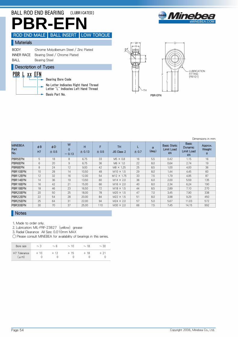
BALL ROD END BEARING 〔LUBRICATED〕
EBEA.COM
eMINPBR-EFN ROD END MALE BALL INSERT LOW TORQUEMaterials
BODY Chrome Molydbenum Steel / Zinc Plated
INNER RACE Bearing Steel / Chrome Plated
BALL Bearing Steel
Description of Types
Dimensions in mm
MINEBEA
Part
No.
φB
H7
φD
± 0.5
W
0
- 0.13
H
± 0.13
F
± 0.5
TH
JIS Class 2
L
± 0.7
α(deg.)
Basic Static
Limit LoadkN
Basic
Dynamic
Limit LoadkN
Approx.
Weightg
PBR5EFN 5 18 8 6.75 33 M5 × 0.8 16 5.5 0.42 1.15 16
PBR6EFN 6 20 9 6.75 36 M6 × 1.0 22 8.0 0.64 2.74 19
PBR8EFN 8 24 12 9.00 42 M8 × 1.25 25 8.5 1.00 4.00 36
PBR10EFN 10 28 14 10.50 48 M10 × 1.5 29 8.0 1.44 4.45 60
PBR12EFN 12 32 16 12.00 54 M12 × 1.75 33 7.5 1.79 4.95 87
PBR14EFN 14 36 19 13.50 60 M14 × 2.0 36 6.0 2.00 5.59 135
PBR16EFN 16 42 21 15.00 66 M16 × 2.0 40 8.0 2.34 6.24 190
PBR18EFN 18 46 23 16.50 72 M18 × 1.5 44 8.5 2.89 7.10 270
PBR20EFN 20 50 25 18.00 78 M20 × 1.5 47 7.0 3.45 7.90 338
PBR22EFN 22 54 28 20.00 84 M22 × 1.5 51 8.0 3.98 9.29 450
PBR25EFN 25 64 31 22.00 94 M24 × 2.0 57 5.0 5.67 11.03 572
PBR30EFN 30 70 37 25.00 110 M30 × 2.0 66 7.5 7.45 14.15 992
Notes
1. Made to order only.2. Lubrication: MIL-PRF-23827(yellow)grease3. Radial Clearance All Size: 0.010mm MAX◯ Please consult MINEBEA for availability of bearings in this series.
Bore size ~ 3 ~ 6 ~ 10 ~ 18 ~ 30
H7 Tolerance
(μm)
+ 10
0
+ 12
0
+ 15
0
+ 18
0
+ 21
0
Page 54 Copyright 2006, Minebea Co., Ltd.

BALL ROD END BEARING 〔LUBRICATED〕
EBEA.COM
eMINPBR-FN ROD END FEMALE BALL INSERT LOW TORQUEMaterials
BODY Chrome Molydbenum Steel / Zinc Plated
INNER RACE Bearing Steel / Chrome Plated
BALL Bearing Steel
Description of Types
Dimensions in mm
MINEBEA
Part
No.
φB
H7
φD
± 0.5
W
0
- 0.13
H
± 0.13
F
± 0.5
TH
JIS Class 2
L
± 0.7
φN
± 0.5
φP
± 0.5
C
+ 0.2
- 0.7
S
± 0.25
α(deg.)
Basic Static
Limit LoadkN
Basic
Dynamic
Limit LoadkN
Approx.
Weightg
PBR5FN 5 18 8 6.75 27 M5 × 0.8 14 9.0 11 4.0 9 5.5 0.42 1.15 20
PBR6FN 6 20 9 6.75 30 M6 × 1.0 12 10.0 135.0
11 8.0 0.64 2.74 24
PBR8FN 8 24 12 9.00 36 M8 × 1.25 16 12.5 16 14 8.5 1.00 4.00 44
PBR10FN 10 28 14 10.50 43 M10 × 1.5 20 15.0 196.5
17 8.0 1.44 4.45 72
PBR12FN 12 32 16 12.00 50 M12 × 1.75 22 17.5 22 19 7.5 1.79 4.95 107
PBR14FN 14 36 19 13.50 57 M14 × 2.0 25 20.0 258.0 22
6.0 2.00 5.59 160
PBR16FN 16 42 21 15.00 64 M16 × 2.0 28 22.0 27 8.0 2.34 6.24 224
PBR18FN 18 46 23 16.50 71 M18 × 1.5 32 25.0 3110.0
27 8.5 2.89 7.10 293
PBR20FN 20 50 25 18.00 77 M20 × 1.5 33 27.5 34 30 7.0 3.45 7.90 367
PBR22FN 22 54 28 20.00 84 M22 × 1.5 3730.0
38 12.0 32 8.0 3.98 9.29 480
PBR25FN 25 64 31 22.00 94 M24 × 2.0 42 35 10.0 30 5.0 5.67 11.03 602
PBR30FN 30 70 37 25.00 110 M30 × 2.0 51 40.0 50 15.0 41 7.5 7.45 14.15 978
Notes
1. Made to order only.2. Lubrication: MIL-PRF-23827(yellow)grease3. Radial Clearance All Size: 0.010mm MAX◯ Please consult MINEBEA for availability of bearings in this series.
Bore size ~ 3 ~ 6 ~ 10 ~ 18 ~ 30
H7 Tolerance
(μm)
+ 10
0
+ 12
0
+ 15
0
+ 18
0
+ 21
0
Page 55Copyright 2006, Minebea Co., Ltd.

High Technology for Professionals
Tel: +41 81 300 40 00 www.mtoswiss.ch Fax: +41 81 300 40 00 [email protected]
MTO & Co. AG